Embed Size (px)
Citation preview

Since 1936 4421 NE Columbia Blvd. Portland, OR 97218 Telephone (503) 288-6411 www.petersonpower.com
Project Manager: Bryan Robinson 503.280.1568 Fax 503.280.1552 [email protected]
ENGINEERING SUBMITTAL FOR APPROVAL
REMOTE FUEL FILL STATION SW BROADWAY TOWER
PREPARED FOR MCKINSTRY CO
PRYCO 230 FAMILY
NEMA 3R OUTDOOR 120VAC, 60HZ, 1PH, FILL STATION ASSEMBLY
PROVIDED BY
PETERSON POWER SYSTEMS, INC. APRIL 11, 2017
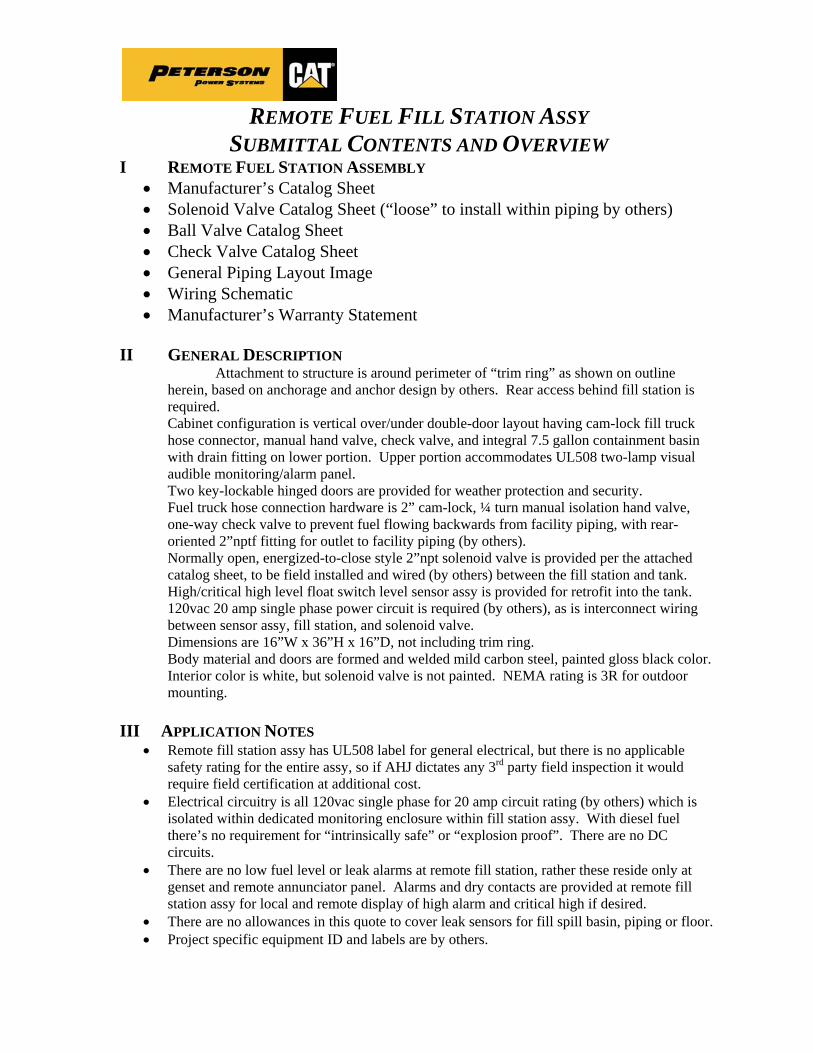
REMOTE FUEL FILL STATION ASSY
SUBMITTAL CONTENTS AND OVERVIEW I REMOTE FUEL STATION ASSEMBLY
Manufacturer’s Catalog Sheet Solenoid Valve Catalog Sheet (“loose” to install within piping by others) Ball Valve Catalog Sheet Check Valve Catalog Sheet General Piping Layout Image Wiring Schematic Manufacturer’s Warranty Statement
II GENERAL DESCRIPTION
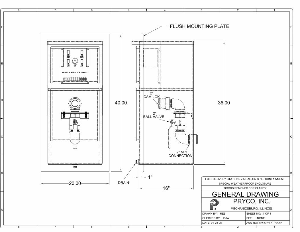
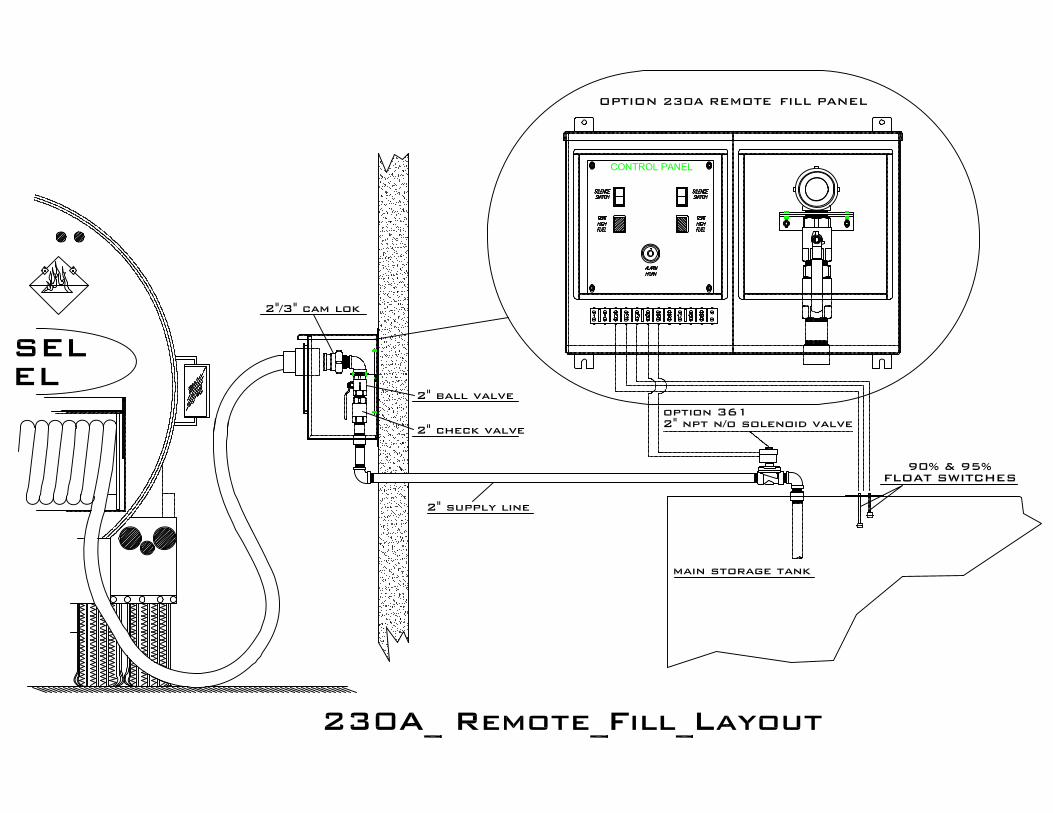
Attachment to structure is around perimeter of “trim ring” as shown on outline herein, based on anchorage and anchor design by others. Rear access behind fill station is required. Cabinet configuration is vertical over/under double-door layout having cam-lock fill truck hose connector, manual hand valve, check valve, and integral 7.5 gallon containment basin with drain fitting on lower portion. Upper portion accommodates UL508 two-lamp visual audible monitoring/alarm panel. Two key-lockable hinged doors are provided for weather protection and security. Fuel truck hose connection hardware is 2” cam-lock, ¼ turn manual isolation hand valve, one-way check valve to prevent fuel flowing backwards from facility piping, with rear-oriented 2”nptf fitting for outlet to facility piping (by others). Normally open, energized-to-close style 2”npt solenoid valve is provided per the attached catalog sheet, to be field installed and wired (by others) between the fill station and tank. High/critical high level float switch level sensor assy is provided for retrofit into the tank. 120vac 20 amp single phase power circuit is required (by others), as is interconnect wiring between sensor assy, fill station, and solenoid valve. Dimensions are 16”W x 36”H x 16”D, not including trim ring. Body material and doors are formed and welded mild carbon steel, painted gloss black color. Interior color is white, but solenoid valve is not painted. NEMA rating is 3R for outdoor mounting.
III APPLICATION NOTES
Remote fill station assy has UL508 label for general electrical, but there is no applicable safety rating for the entire assy, so if AHJ dictates any 3rd party field inspection it would require field certification at additional cost.
Electrical circuitry is all 120vac single phase for 20 amp circuit rating (by others) which is isolated within dedicated monitoring enclosure within fill station assy. With diesel fuel there’s no requirement for “intrinsically safe” or “explosion proof”. There are no DC circuits.
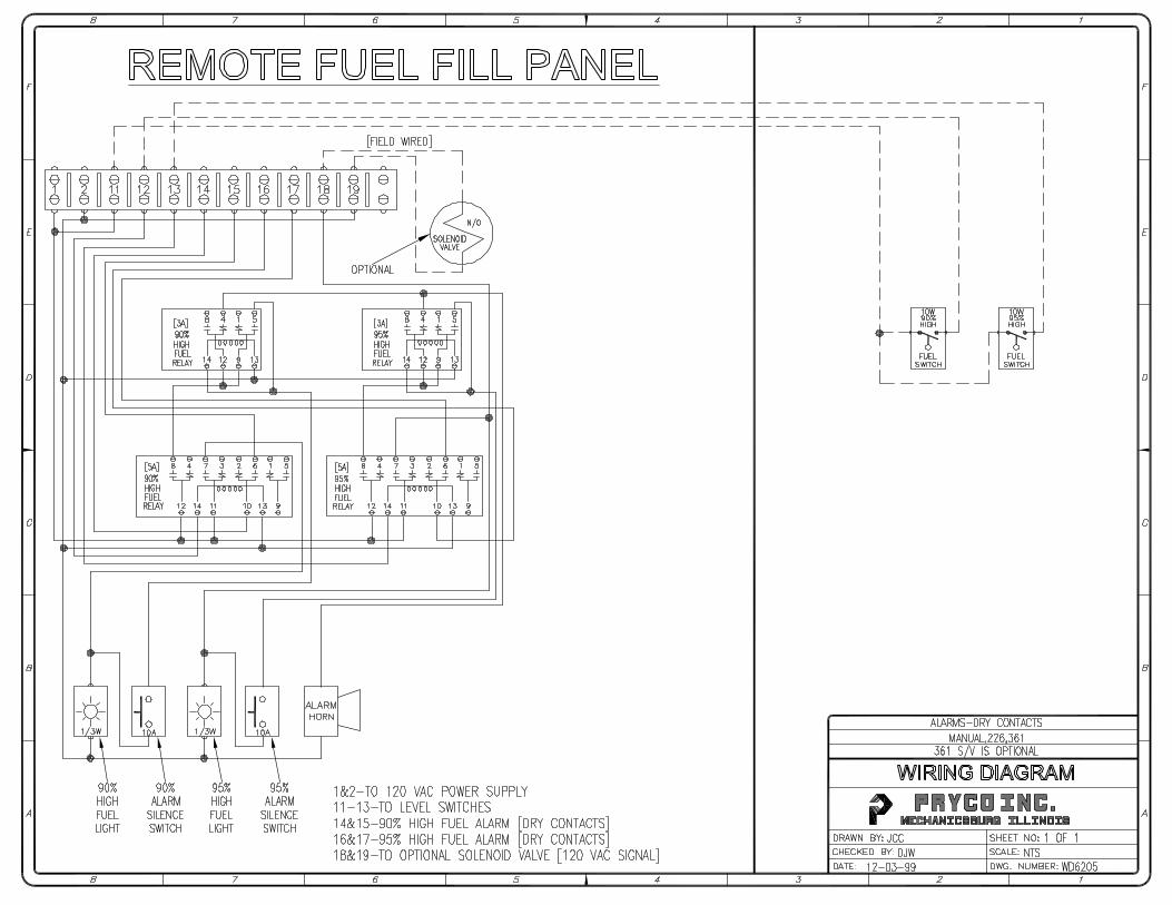
There are no low fuel level or leak alarms at remote fill station, rather these reside only at genset and remote annunciator panel. Alarms and dry contacts are provided at remote fill station assy for local and remote display of high alarm and critical high if desired.
There are no allowances in this quote to cover leak sensors for fill spill basin, piping or floor. Project specific equipment ID and labels are by others.
P.O. Box 108, Mechanicsburg, IL 62545 Phone - 217 / 364-4467 Fax - 217 / 364-4494
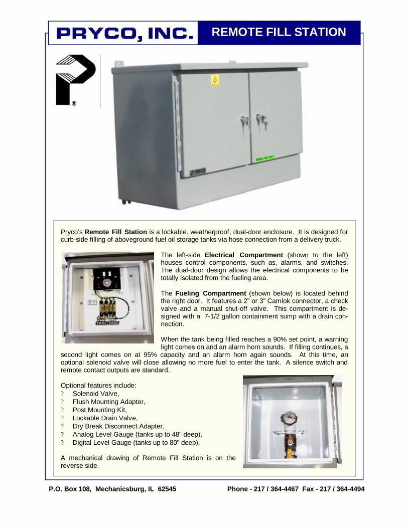
Pryco’s Remote Fill Station is a lockable. weatherproof, dual-door enclosure. It is designed for curb-side filling of aboveground fuel oil storage tanks via hose connection from a delivery truck.
The left-side Electrical Compartment (shown to the left) houses control components, such as, alarms, and switches. The dual-door design allows the electrical components to be totally isolated from the fueling area. The Fueling Compartment (shown below) is located behind the right door. It features a 2” or 3” Camlok connector, a check valve and a manual shut-off valve. This compartment is de-signed with a 7-1/2 gallon containment sump with a drain con-nection. When the tank being filled reaches a 90% set point, a warning light comes on and an alarm horn sounds. If filling continues, a
second light comes on at 95% capacity and an alarm horn again sounds. At this time, an optional solenoid valve will close allowing no more fuel to enter the tank. A silence switch and remote contact outputs are standard. Optional features include: ? Solenoid Valve, ? Flush Mounting Adapter, ? Post Mounting Kit, ? Lockable Drain Valve, ? Dry Break Disconnect Adapter, ? Analog Level Gauge (tanks up to 48” deep), ? Digital Level Gauge (tanks up to 80” deep), A mechanical drawing of Remote Fill Station is on the reverse side.
REMOTE FILL STATION

PRYCO’s Option #361
Magnatrol Valve Corporation SOLENOID VALVE
Type AR Full Port - Normally Open Internal Pilot Operated
Operation: Valve closes when energized and opens when de-energized. When the coil is energized, the laminated plunger presses the poppet closing the pilot orifice and opens a bleed passageway to permit pressure to build above the piston and seating it. Upon de-energizing the coil, the pilot orifice opens relieving the pressure above the piston allowing it to leave its seat. The bottom spring allows the valve to operate at zero-pressure drop.
Pipe Size: 1/2 in. to 3 in. Max. Fluid Temperature: 212 deg. F Max. Static Pressure: 300 psi, except valves listed for 500-PSI differential
Construction:
*Valve Body - Cast Bronze, Globe Pattern *Piston - Cast Bronze Coil Enclosure - Malleable or Cast Iron *Plunger - 430 Stainless Steel *Pilot (Poppet) Valve - 303 Stainless Steel *Stem - 303 Stainless Steel *Bonnet Tube - 304 Stainless Steel *Spring – Inconel and 302 Stainless Steel *Body Seal - Buna N or Non Asbestos Gasket *Orifice Seal - Buna N (Viton® or Glass Filled Teflon available) *AC Shading Coil - Copper *Stem Pin - 304 Stainless Steel Coil - Encapsulated, Class A, 18" Leads (Class H Available) * Wetted parts in contact with fluid
Application: To control the flow of water, oil, air, gas, solvents, brine, vacuum and any other fluids not reactive with construction materials and free of sediment. Valve operates from zero to maximum differential pressure indicated in table. Valve must be mounted in horizontal pipe with solenoid enclosure vertical and on top.
NO DIFFERENTIAL PRESSURE REQUIRED TO OPEN
Dimensions, Inches Pipe Size, In.
Max. Diff. Pres. PSI
Type No. Watts AC
Amps Hold,
120-60
Amps Inrush 120-60
Watts DC
Ship Wt. Lbs. A B C D
110 18AR42 200 18AR32 300 18AR52
25 0.4 1.2 18 8 7 5-7/8 2-3/4 3-1/4 1/2
500 E33AR62 45 0.8 2.4 23 16 8 6-7/8 4-1/8 3-1/4 50 18AR23 110 18AR43
25 0.4 1.3 18
160 118AR43 40 0.6 2.0 28 8 7-1/8 6 2-3/4 3-1/2
200 33AR33 300 33AR53
45 0.8 2.6 23 12 8-1/8 7 3-1/2 3-1/2 3/4
500 E133AR63 65 1.2 3.9 33 17 8-1/8 7 4-1/8 3-1/2 50 18AR24 110 18AR44
25 0.4 1.5 18
160 118AR44 40 0.6 2.3 28 10 7-7/8 6-5/8 2-3/4 4-1/8
200 33AR34 300 33AR54
45 0.8 2.8 23 14 8-7/8 7-1/2 3-1/2 4-1/8 1
500 E133AR64 65 1.2 4.2 33 19 8-7/8 7-1/2 4-1/8 4-1/8 50 18AR25 90 18AR45
25 0.4 1.6 18
150 118AR45 40 0.6 2.4 28 12 8-3/8 6-3/4 2-3/4 4-1/2
200 33AR35 300 33AR55
45 0.8 3.0 23 16 9-3/8 7-3/4 3-1/2 4-1/2 1-1/4
500 40AR65
Not for DC Operation
60 1.2 6.2 - 20 10-3/8 8-3/4 4-1/2 4-1/2
50 35AR26 115 35AR46
45 0.8 3.2 23
160 135AR46 65 1.2 4.8 33 20 10 8-1/8 4 4-7/8
200 41AR36 300 41AR56
60 1.2 6.7 35 1-1/2
500 141AR66 85 2.0 10.0 45 24 11 9-1/8 4-1/2 4-7/8
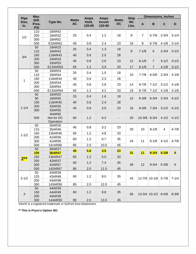
50 36AR27 100 36AR47
45 0.8 3.5 23
150 136AR47 65 1.2 5.0 33 31 11 8-3/4 5-3/8 6
200 42AR37 300 42AR57
60 1.2 7.4 35 2**
500 142AR67 85 2.0 11.0 45 36 12 9-3/4 5-3/8 6
50 43AR28 125 43AR48 200 43AR38
60 1.2 8.0 35 2-1/2
300 143AR58 85 2.0 12.0 45
43 12-7/8 10-1/8 5-7/8 7-1/4
50 44AR29 100 44AR49 200 44AR39
60 1.2 8.8 35 3
300 144AR59 85 2.0 13.0 45
56 13-3/4 10-1/2 6-5/8 8-3/8
Viton® is a registered trademark or DuPont Dow Elastomers ** This is Pryco’s Option 361

COPYRIGHT ©2011 APOLLO VALVES, MANUFACTURED BY CONBRACO INDUSTRIES – PRINTED IN U.S.A.
NUMBER SIZE A B C D E Wt.70-101-01 1/4” .37 1.03 2.06 1.75 3.87 .6070-102-01 3/8” .37 1.03 2.06 1.75 3.87 .5670-103-01 1/2” .50 1.12 2.25 1.75 3.87 .6370-104-01 3/4” .68 1.50 3.00 2.12 4.87 1.3970-105-01 1” .87 1.68 3.37 2.25 4.87 1.7270-106-01 1-1/4” 1.00 2.00 4.00 2.62 5.50 3.2670-107-01 1-1/2” 1.25 2.18 4.37 3.06 8.00 4.6170-108-01 2” 1.50 2.34 4.68 3.25 8.00 6.06
70-109-01A 2-1/2” 2.00 3.12 6.25 3.72 8.00 17.2570-100-01 3” 2.50 3.37 6.75 4.12 8.00 18.6070-10A-01 4” 3.12 3.69 7.37 5.25 9.94 25.50
70-100 SeriesBronze Ball Valve
Threaded, 600 psig WOG, Cold Non-Shock. 150 psig Saturated Steam. (See referenced P/T charts)Vacuum Service to 29 inches Hg.Federal Specification: WW-V-35C, Type: II, Composition: BZ, Style: 3.MSS SP-110; Ball Valves Threaded, Socket-Welding, Solder Joint, Grooved and Flared Ends.
FEATURES• Two-piece body • Blow-out-proof stem design• Reinforced seats • Adjustable packing gland
STANDARD MATERIAL LIST1. Lever and grip Steel, zinc plated w/vinyl 7. Gland nut B162. Stem packing MPTFE 8. Stem B163. Stem bearing RPTFE 9. Lever nut Steel, zinc plated4. Ball B16, chrome plated 10. Body seal PTFE5. Seat (2) RPTFE (1-1/4” to 4”)6. Retainer B16 (1/4” to 1”) 11. Body B584-C84400
B584-C84400 (1-1/4” to 4”)
VARIATIONS AVAILABLE:70-140 Series (316 SS Ball & Stem)70-190 Series (Locked Retainer)
OPTIONS AVAILABLE:(SUFFIX) OPTION SIZES-02- Stem Grounded 1/4” to 4”-04- 2-1/4” CS Stem Extension 1/4” to 3”-05- Plain Ball 1/4” to 3”-07- Steel Tee Handle 1/4” to 2”-08- 90º Reversed Stem 1/4” to 3”-10- SS Lever & Nut 1/4” to 3”-11- Therma-Seal™ Insulating Tee Handle 1/4” to 2”-14- Side Vented Ball (Uni-Directional) 1/4” to 4”-15- Wheel Handle, Steel 1/4” to 2”-16- Chain Lever - Vertical 3/4” to 2”-17- Rough Chrome Plated - Bronze Valves 1/4” to 3”-21- UHMWPE Trim (Non-PTFE) 1/4” to 3”-24- Graphite Packing 1/4” to 3”-27- SS Latch-Lock Lever & Nut 1/4” to 3”-30- Cam-Lock and Grounded 1/4” to 2”-32- SS Tee Handle & Nut 1/4” to 2”-35- VTFE Trim 1/4” to 3”-36- SS Hi-Rise Round Handle, SS Nut 1/4” to 2”-39- SS Hi-Rise Locking Wheel Handle, SS Nut 1/4” to 2”-40- Cyl-Loc and Grounded 1/4” to 2”-41- Automatic Drain (Bronze Valves Only) 1/4” to 2”
see page J-8-45- Less Lever & Nut 1/4” to 3”-46- Latch Lock Lever - Lock in Closed Position Only 1/4” to 3”-47- SS Oval Latch-Lock Handle & Nut 1/4” to 1”-48- SS Oval Handle (No Latch) & Nut 1/4” to 2”-49- Assembled Dry 1/4” to 4”-50- 2-1/4” CS Locking Stem Extension 1/4” to 3”-56- Multifill Seats & Packing 1/4” to 3”-57- Oxygen Cleaned 1/4” to 4”-58- Chain Lever - Horizontal 3/4” to 2”-60- Static Grounded Ball & Stem 1/4” to 3”-63- NPT x Solder/Socket Weld 3/8” to 4”-64- 250# Steam Trim 1/4” to 3”-92- Balancing Stop 1/4” to 3”-HC- Hose Cap & Chain 1/2” to 1”-P01- BSPP (Parallel) Thread Connection 1/4” to 3”-T01- BSPT (Tapered) Thread Connection 1/4” to 3”
BRONZE BALL VALVE
A-1
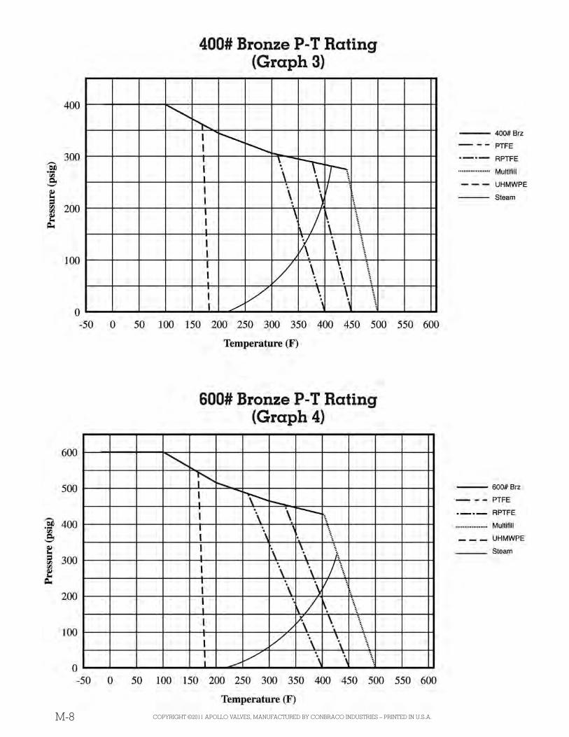
For Pressure/Temperature Ratings,Refer to Page M-8, Graph No. 4
M-1COPYRIGHT ©2011 APOLLO VALVES, MANUFACTURED BY CONBRACO INDUSTRIES – PRINTED IN U.S.A.
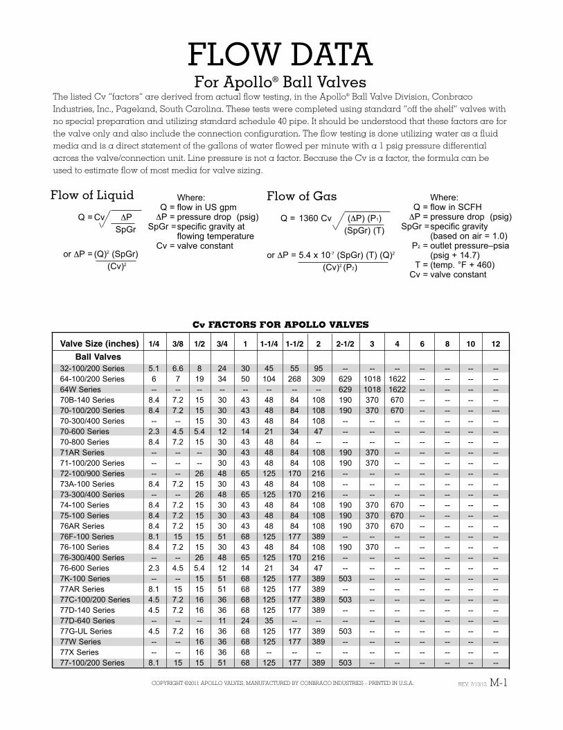
FLOW DATAFor Apollo® Ball Valves
The listed Cv “factors” are derived from actual flow testing, in the Apollo® Ball Valve Division, ConbracoIndustries, Inc., Pageland, South Carolina. These tests were completed using standard “off the shelf” valves withno special preparation and utilizing standard schedule 40 pipe. It should be understood that these factors are forthe valve only and also include the connection configuration. The flow testing is done utilizing water as a fluidmedia and is a direct statement of the gallons of water flowed per minute with a 1 psig pressure differentialacross the valve/connection unit. Line pressure is not a factor. Because the Cv is a factor, the formula can beused to estimate flow of most media for valve sizing.
Flow of Liquid
Q = Cv ΔPSpGr
or ΔP = (Q)2 (SpGr)(Cv)2
Flow of Gas
Q = 1360 Cv (ΔP) (P1)(SpGr) (T)
or ΔP = 5.4 x 10⁻⁷ (SpGr) (T) (Q)2
(Cv)2 (P2)
Where:Q = flow in SCFHΔP = pressure drop (psig)
SpGr =specific gravity(based on air = 1.0)
P2 = outlet pressure–psia(psig + 14.7)
T = (temp. °F + 460)Cv = valve constant
Where:Q = flow in US gpmΔP = pressure drop (psig)
SpGr =specific gravity atflowing temperature
Cv = valve constant
Cv FACTORS FOR APOLLO VALVES
Valve Size (inches) 1/4 3/8 1/2 3/4 1 1-1/4 1-1/2 2 2-1/2 3 4 6 8 10 12
Ball Valves32-100/200 Series 5.1 6.6 8 24 30 45 55 95 -- -- -- -- -- -- --64-100/200 Series 6 7 19 34 50 104 268 309 629 1018 1622 -- -- -- --64W Series -- -- -- -- -- -- -- -- 629 1018 1622 -- -- -- --70B-140 Series 8.4 7.2 15 30 43 48 84 108 190 370 670 -- -- -- --70-100/200 Series 8.4 7.2 15 30 43 48 84 108 190 370 670 -- -- -- ---70-300/400 Series -- -- 15 30 43 48 84 108 -- -- -- -- -- -- --70-600 Series 2.3 4.5 5.4 12 14 21 34 47 -- -- -- -- -- -- --70-800 Series 8.4 7.2 15 30 43 48 84 -- -- -- -- -- -- -- --71AR Series -- -- -- 30 43 48 84 108 190 370 -- -- -- -- --71-100/200 Series -- -- -- 30 43 48 84 108 190 370 -- -- -- -- --72-100/900 Series -- -- 26 48 65 125 170 216 -- -- -- -- -- -- --73A-100 Series 8.4 7.2 15 30 43 48 84 108 -- -- -- -- -- -- --73-300/400 Series -- -- 26 48 65 125 170 216 -- -- -- -- -- -- --74-100 Series 8.4 7.2 15 30 43 48 84 108 190 370 670 -- -- -- --75-100 Series 8.4 7.2 15 30 43 48 84 108 190 370 670 -- -- -- --76AR Series 8.4 7.2 15 30 43 48 84 108 190 370 670 -- -- -- --76F-100 Series 8.1 15 15 51 68 125 177 389 -- -- -- -- -- -- --76-100 Series 8.4 7.2 15 30 43 48 84 108 190 370 -- -- -- -- --76-300/400 Series -- -- 26 48 65 125 170 216 -- -- -- -- -- -- --76-600 Series 2.3 4.5 5.4 12 14 21 34 47 -- -- -- -- -- -- --7K-100 Series -- -- 15 51 68 125 177 389 503 -- -- -- -- -- --77AR Series 8.1 15 15 51 68 125 177 389 -- -- -- -- -- -- --77C-100/200 Series 4.5 7.2 16 36 68 125 177 389 503 -- -- -- -- -- --77D-140 Series 4.5 7.2 16 36 68 125 177 389 -- -- -- -- -- -- --77D-640 Series -- -- -- 11 24 35 -- -- -- -- -- -- -- -- --77G-UL Series 4.5 7.2 16 36 68 125 177 389 503 -- -- -- -- -- --77W Series -- -- 16 36 68 125 177 389 -- -- -- -- -- -- --77X Series -- -- 16 36 68 -- -- -- -- -- -- -- -- -- --77-100/200 Series 8.1 15 15 51 68 125 177 389 503 -- -- -- -- -- --
REV. 7/13/12
M-2 COPYRIGHT ©2011 APOLLO VALVES, MANUFACTURED BY CONBRACO INDUSTRIES – PRINTED IN U.S.A.
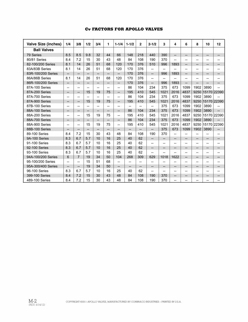
Cv FACTORS FOR APOLLO VALVES
Valve Size (inches) 1/4 3/8 1/2 3/4 1 1-1/4 1-1/2 2 2-1/2 3 4 6 8 10 12
Ball Valves79 Series 8.5 8.5 9.8 32 44 66 148 218 440 390 -- -- -- -- --80/81 Series 8.4 7.2 15 30 43 48 84 108 190 370 -- -- -- -- --82-100/200 Series 8.1 14 26 51 68 120 170 376 510 996 1893 -- -- -- --83A/83B Series 8.1 14 26 51 68 120 170 376 -- -- -- -- -- -- --83R-100/200 Series -- -- -- -- -- -- 170 376 -- 996 1893 -- -- -- --86A/86B Series 8.1 14 26 51 68 120 170 376 -- -- -- -- -- -- --86R-100/200 Series -- -- -- -- -- -- 170 376 -- 996 1893 -- -- -- --87A-100 Series -- -- -- -- -- -- 86 104 234 375 673 1099 1902 3890 --87A-200 Series -- -- 15 19 75 -- 195 410 545 1021 2016 4837 9250 15170 2239087A-700 Series -- -- -- -- -- -- 86 104 234 375 673 1099 1902 3890 --87A-900 Series -- -- 15 19 75 -- 195 410 545 1021 2016 4837 9250 15170 2239087B-100 Series -- -- -- -- -- -- -- -- -- 375 673 1099 1902 3890 --88A-100 Series -- -- -- -- -- -- 86 104 234 375 673 1099 1902 3890 --88A-200 Series -- -- 15 19 75 -- 195 410 545 1021 2016 4837 9250 15170 2239088A-700 Series -- -- -- -- -- -- 86 104 234 375 673 1099 1902 3890 --88A-900 Series -- -- 15 19 75 -- 195 410 545 1021 2016 4837 9250 15170 2239088B-100 Series -- -- -- -- -- -- -- -- -- 375 673 1099 1902 3890 --89-100 Series 8.4 7.2 15 30 43 48 84 108 190 370 -- -- -- -- --9A-100 Series 8.3 6.7 5.7 10 16 25 40 62 -- -- -- -- -- -- --91-100 Series 8.3 6.7 5.7 10 16 25 40 62 -- -- -- -- -- -- --92-100 Series 8.3 6.7 5.7 10 16 25 40 62 -- -- -- -- -- -- --93-100 Series 8.3 6.7 5.7 10 16 25 40 62 -- -- -- -- -- -- --94A-100/200 Series 6 7 19 34 50 104 268 309 629 1018 1622 -- -- -- --95-100/200 Series -- -- 15 51 68 -- -- -- -- -- -- -- -- -- --95A-300/400 Series -- -- 19 34 50 -- -- -- -- -- -- -- -- -- --96-100 Series 8.3 6.7 5.7 10 16 25 40 62 -- -- -- -- -- -- --399-100 Series 8.4 7.2 15 30 43 48 84 108 190 370 -- -- -- -- --489-100 Series 8.4 7.2 15 30 43 48 84 108 190 370 -- -- -- -- --
(REV. 6/14/12)
M-8 COPYRIGHT ©2011 APOLLO VALVES, MANUFACTURED BY CONBRACO INDUSTRIES – PRINTED IN U.S.A.
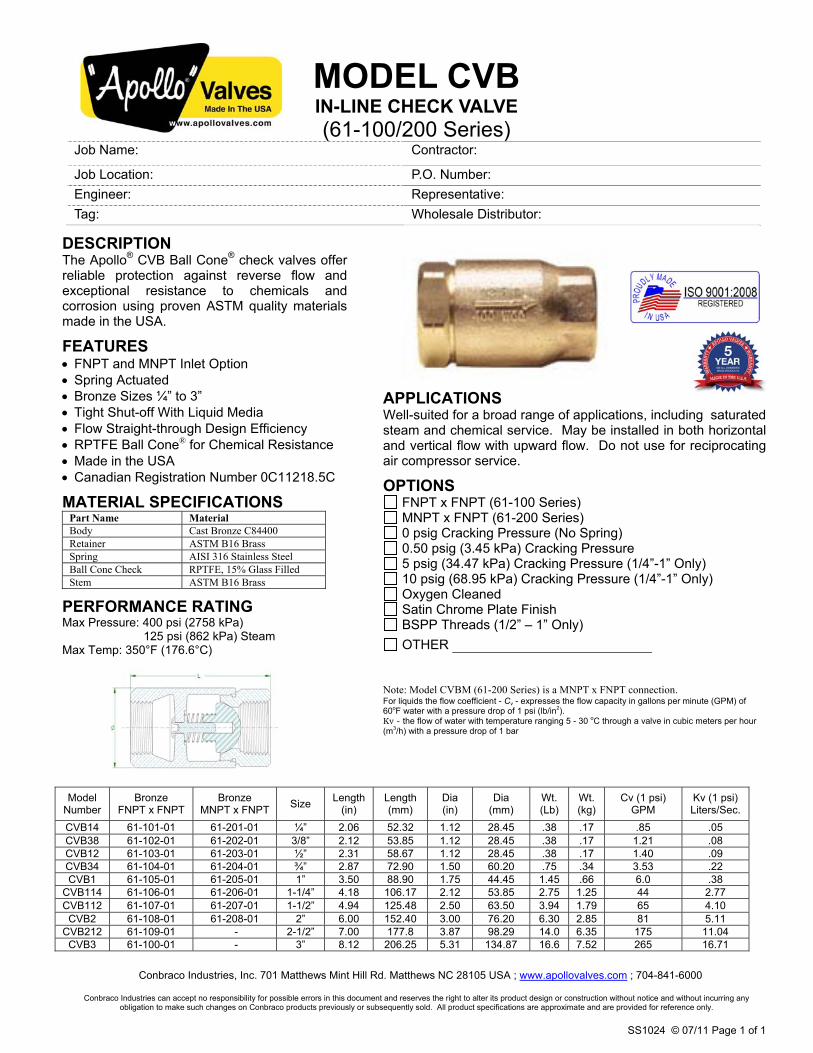
MODEL CVB IN-LINE CHECK VALVE (61-100/200 Series)
Conbraco Industries, Inc. 701 Matthews Mint Hill Rd. Matthews NC 28105 USA ; www.apollovalves.com
Job Name: Contractor:
Job Location: P.O. Number: Engineer: Representative: Tag: Wholesale Distributor:
DESCRIPTION
; 704-841-6000
Conbraco Industries can accept no responsibility for possible errors in this document and reserves the right to alter its product design or construction without notice and without incurring any obligation to make such changes on Conbraco products previously or subsequently sold. All product specifications are approximate and are provided for reference only.
SS1024 © 07/11 Page 1 of 1
The Apollo® CVB Ball Cone® check valves offer reliable protection against reverse flow and exceptional resistance to chemicals and corrosion using proven ASTM quality materials made in the USA.
FEATURES x FNPT and MNPT Inlet Option x Spring Actuated x Bronze Sizes ¼” to 3” x Tight Shut-off With Liquid Media x Flow Straight-through Design Efficiency x RPTFE Ball Cone® for Chemical Resistance x Made in the USA x Canadian Registration Number 0C11218.5C
MATERIAL SPECIFICATIONS Part Name Material Body Cast Bronze C84400 Retainer ASTM B16 Brass Spring AISI 316 Stainless Steel Ball Cone Check RPTFE, 15% Glass Filled Stem ASTM B16 Brass
PERFORMANCE RATING Max Pressure: 400 psi (2758 kPa)
125 psi (862 kPa) Steam Max Temp: 350°F (176.6°C)
APPLICATIONS Well-suited for a broad range of applications, including saturated steam and chemical service. May be installed in both horizontal and vertical flow with upward flow. Do not use for reciprocating air compressor service.
OPTIONS FNPT x FNPT (61-100 Series) MNPT x FNPT (61-200 Series) 0 psig Cracking Pressure (No Spring) 0.50 psig (3.45 kPa) Cracking Pressure 5 psig (34.47 kPa) Cracking Pressure (1/4”-1” Only) 10 psig (68.95 kPa) Cracking Pressure (1/4”-1” Only) Oxygen Cleaned Satin Chrome Plate Finish BSPP Threads (1/2” – 1” Only) OTHER � � � � � � � � � � � � � � � � � � � � � � � � � � � � � �
Note: Model CVBM (61-200 Series) is a MNPT x FNPT connection. For liquids the flow coefficient - Cv - expresses the flow capacity in gallons per minute (GPM) of 60oF water with a pressure drop of 1 psi (lb/in2). Kv - the flow of water with temperature ranging 5 - 30 oC through a valve in cubic meters per hour (m3/h) with a pressure drop of 1 bar
Model Number
Bronze FNPT x FNPT
Bronze MNPT x FNPT Size Length
(in) Length (mm)
Dia (in)
Dia (mm)
Wt. (Lb)
Wt. (kg)
Cv (1 psi) GPM
Kv (1 psi) Liters/Sec.
CVB14 61-101-01 61-201-01 ¼” 2.06 52.32 1.12 28.45 .38 .17 .85 .05 CVB38 61-102-01 61-202-01 3/8” 2.12 53.85 1.12 28.45 .38 .17 1.21 .08 CVB12 61-103-01 61-203-01 ½” 2.31 58.67 1.12 28.45 .38 .17 1.40 .09 CVB34 61-104-01 61-204-01 ¾” 2.87 72.90 1.50 60.20 .75 .34 3.53 .22 CVB1 61-105-01 61-205-01 1” 3.50 88.90 1.75 44.45 1.45 .66 6.0 .38
CVB114 61-106-01 61-206-01 1-1/4” 4.18 106.17 2.12 53.85 2.75 1.25 44 2.77 CVB112 61-107-01 61-207-01 1-1/2” 4.94 125.48 2.50 63.50 3.94 1.79 65 4.10
CVB2 61-108-01 61-208-01 2” 6.00 152.40 3.00 76.20 6.30 2.85 81 5.11 CVB212 61-109-01 - 2-1/2” 7.00 177.8 3.87 98.29 14.0 6.35 175 11.04
CVB3 61-100-01 - 3” 8.12 206.25 5.31 134.87 16.6 7.52 265 16.71
Page 1
PRYCO, INC.
P. O. Box 108, Mechanicsburg, IL 62545 — Phone 217 / 364-4467
OPERATIONS
and
MAINTENANCE
MANUAL
For
REMOTE FUEL FILL
PANEL and STATION
PRYCO, INC. P. O. BOX 108 Mechanicsburg, IL 62545
Telephone: 217 / 364-4467 Fax: 217 / 364-4494

PRYCO, INC.
P. O. Box 108, Mechanicsburg, IL 62545 — Phone 217 / 364-4467 Page 2
WHAT TO DO FIRST
Upon receiving your new Remote Fuel Fill Panel or Station, always check for physical signs of damages before signing the bill of lading. All products are inspected at point of shipment to ensure they are free of any defects. Dropping and other rough handling in transit could place stress or break welds and plumbing joints that will result in a failure. Check to ensure the system equip-ment arrives in good condition. Report any damage or irregularities to: Traffic Coordinator Pryco, Inc. 3rd & Garvey Streets Mechanicsburg, IL 62545 Phone 217 / 364-4467 Fax: 217 / 364-4494 Email: [email protected]
INSTALLATION
Always have the system installed by trained, authorized personnel. Remove shipping plugs from all connection fittings. Check to ensure any overflow line is continuous to the main storage tank without valves and traps (NFPA 37). Pryco fuel systems are designed for open venting. Before starting the system, perform a final check of all pipe fittings for tightness. IMPORTANT - Always clear fuel lines of debris resulting from pipe cutting and threading and other installation processes. Failure to do so may result in fuel contamination that will injure injectors and other engine components.
OPERATIONS
The Remote Fuel Fill Panel is basically a monitoring device and has no spe-cific operation. However, the fueling operator should be alert to the alarm sound and light and cease operation accordingly. The fueling operator connects the delivery vehicle nozzle to the Remote Fuel Fill Station Camlok® connector and ensures the manual shut-off valve is in the open position. The operator then begins fueling alert to the monitoring alarm horn and light and ceases the delivery accordingly.
MAINTENANCE
The system is basically “maintenance free”. Periodic cleaning, interior and ex-terior to remove dust and other foreign debris will prevent most problems. Al-so, test the alarm horn and lights semi–annually to ensure the alarm integrity.
Page 3
PRYCO, INC.
P. O. Box 108, Mechanicsburg, IL 62545 — Phone 217 / 364-4467
PRODUCT DESCRIPTIONS
OPTION 226
REMOTE FUEL FILL PANEL
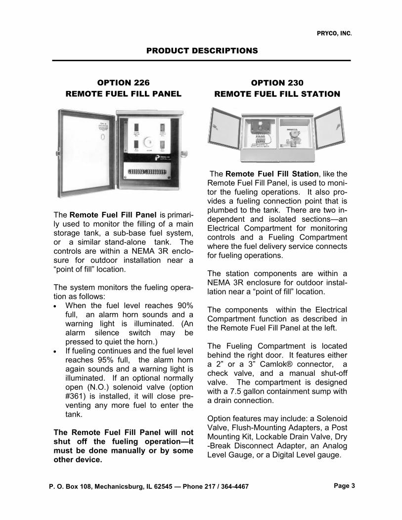
The Remote Fuel Fill Panel is primari-ly used to monitor the filling of a main storage tank, a sub-base fuel system, or a similar stand-alone tank. The controls are within a NEMA 3R enclo-sure for outdoor installation near a “point of fill” location. The system monitors the fueling opera-tion as follows: When the fuel level reaches 90%
full, an alarm horn sounds and a warning light is illuminated. (An alarm silence switch may be pressed to quiet the horn.)
If fueling continues and the fuel level reaches 95% full, the alarm horn again sounds and a warning light is illuminated. If an optional normally open (N.O.) solenoid valve (option #361) is installed, it will close pre-venting any more fuel to enter the tank.
The Remote Fuel Fill Panel will not shut off the fueling operation—it must be done manually or by some other device.
OPTION 230
REMOTE FUEL FILL STATION
The Remote Fuel Fill Station, like the Remote Fuel Fill Panel, is used to moni-tor the fueling operations. It also pro-vides a fueling connection point that is plumbed to the tank. There are two in-dependent and isolated sections—an Electrical Compartment for monitoring controls and a Fueling Compartment where the fuel delivery service connects for fueling operations. The station components are within a NEMA 3R enclosure for outdoor instal-lation near a “point of fill” location. The components within the Electrical Compartment function as described in the Remote Fuel Fill Panel at the left. The Fueling Compartment is located behind the right door. It features either a 2” or a 3” Camlok® connector, a check valve, and a manual shut-off valve. The compartment is designed with a 7.5 gallon containment sump with a drain connection. Option features may include: a Solenoid Valve, Flush-Mounting Adapters, a Post Mounting Kit, Lockable Drain Valve, Dry-Break Disconnect Adapter, an Analog Level Gauge, or a Digital Level gauge.

PRYCO, INC.
P. O. Box 108, Mechanicsburg, IL 62545 — Phone 217 / 364-4467 Page 4
WARRANTY
PRYCO, INC.
All sales by PRYCO, INC., are subject to the following terms and conditions as its Warranties:
1. WARRANTIES – Seller warrants the Goods will be as described on the face hereof, will be free from any defects in material and workmanship at the time of delivery and will be manufactured in accord-ance with the Fair Labor Standard Act of 1938, as amended. SELLER MAKES NO OTHER WAR-RANTY, EXPRESS OR IMPLIED, AND ALL IMPLIED WARRANTIES, INCLUDING WITHOUT LIMI-TATION, IMPLIED WARRANTIES OF MERCHANTABILITY AND FITNESS FOR A PARTICULAR PURPOSE, ARE HEREBY DISCLAIMED. In order to assert a claim for breach of warranty, Buyer must contact Seller within one (1) year from date of sale determined by invoice date and which Seller’s examination shall disclose to its satisfaction to thus defective. This remedy is agreed by Buy-er and Seller to constitute a sole and exclusive remedy and all sales are made subject to the condi-tions that Seller is not liable for consequential damage or for personal injuries of Buyer or its agents thereof. Seller will not warrant installation of Goods by Buyer or its agents. Seller will not be responsi-ble for service, labor or other expenses incurred by buyer, their customers or agent for replacement of defective goods.
2. EXCLUSIVE REMEDY – The exclusive remedy of the Buyer for any breach of the warranties set out in Section (2) will be, in Seller’s sole discretion, the replacement or repair of the Defective Goods provided Buyer pays shipping charges for return of such Goods to Sell-er.
3. LIMITATION OF DAMAGE – In the event of a breach hereof, Seller will not under any circumstance be liable for consequential or incidental damage or expenses of the Buyer including without limitation lost profits, whether or not the Seller has been advised of the same.
4. BUYER’S INDEMNITY – The Buyer shall indemnify and hold Seller harmless from and against any and all losses, damages and expenses (including attorneys’ fees and other costs of defending any action) that the Seller may sustain or incur as a result of any claim of negligence, breach of implied warranty or strict liability by the Buyer, its successors, agents, assigns or customers, whether direct or indirect, in connection with the use of the Goods.
PRYCO, INC. P. O. BOX 108
Mechanicsburg, IL 62545
FACTORY TESTING PROCEDURES
All systems are carefully tested for proper operation. Power is applied to the unit and all aspects of the operation are tested. Alarms are tested by manually creat-ing abnormal conditions in the sequences of operation. All reset and test switches are checked for proper operation.
Telephone: 217 / 364-4467
Fax: 217 / 364-4494
Web Site: www.Pryco.com Email: [email protected]