Embed Size (px)
Citation preview

* Corresponding author. E-mail addresses: [email protected] (B. Mohammadi) © 2013 Growing Science Ltd. All rights reserved. doi: 10.5267/j.esm.2014.2.001
Engineering Solid Mechanics 2 (2014) 101-118
Contents lists available at GrowingScience
Engineering Solid Mechanics
homepage: www.GrowingScience.com/esm
Investigation of delamination and damage due to free edge effects in composite laminates using cohesive interface elements
Bijan Mohammadi* and Davood Salimi-Majd
School of Mechanical Engineering, Iran University of Science & Technology, Narmak, 16846-13114, Tehran, Iran
A R T I C L E I N F O A B S T R A C T
Article history: Received September 20, 2013 Received in Revised form October, 14, 2013 Accepted 9 February 2014 Available online 12 February 2014
Composite materials due to high strength and stiffness to their weight ratio are widely used in different structures. Hence, it is necessary to predict their failure behavior under loading. The delamination due to interlaminar stresses at free edges is one of the most important damage modes in laminated composites. In this study, this mode in cross-ply and angle-ply laminates has been investigated using a cohesive zone model. The advantage of this method is the possibility of modeling the delamination initiation and propagation without requirement to the presence of initial crack and remeshing. Hence, at first an interface element based on bilinear cohesive law was implemented in Ansys. Next, laminated plates with different lay-ups under uniaxial tension loading were modeled. Also Hashin’s failure criteria were used to predict ply damage initiation. Numerical results show that in angle-ply laminates with small fiber angle orientation, delamination in the shear mode is the dominant mode in the loss of structural strength. The numerical and experimental results for global load-displacement response show a good agreement. Also numerical results show that in cross-ply laminates even under in-plane loading, the damage behavior extremely depends on the stacking sequence. Studies show that in cross-ply laminates under uniaxial tension, if 90o plies are inserted in top and bottom surface of the laminate, the mode I delamination and matrix cracking will start later.
© 2014 Growing Science Ltd. All rights reserved.
Keywords: Delamination Cohesive zone model Damage variable Matrix cracking Free edge effects
1. Introduction
Due to the extensive use of composite materials, it is necessary to analysis their behavior and design them well. In this regard, one of the important points is to define suitable failure criteria. Among the different failure modes in laminated composites, the delamination is one of the main damage mechanisms, which is created between two adjacent layers and can decrease performance of the desired structure. In general, all the mechanisms that lead to the out of plane stresses in laminated composites, can lead to the delamination. Among these mechanisms are the interlaminar stresses created around the edges due to the mismatch of mechanical properties in adjacent layers. The most

102
important of these properties are the Poisson ratio (xy) and the coefficient of mutual influence (xy). The mismatching of Poisson ratio in adjacent layers usually causes to the delamination in opening mode. Also the mismatching of coefficient of mutual influence in adjacent layers increases the possibility of delamination in shear mode. Because of the complex nature of stresses around the edges, estimation of initiation and propagation of delamination due to the edge effects is very difficult and yet important. Hence, this research has been focused on this subject.
According to the contents expressed above, because of the importance of delamination in failure of composite structures, this failure mode has been investigated by many researchers. Pagano and Pipes (1973) research is one of the first investigations on the delamination. They investigated the effective parameters on interlaminar stresses based on the fiber angle orientation. Based on a plasticity-like model, Weeks and Sun (1998) investigated the damage of composite materials with different lay-ups and compared their results with the experimental ones. Despite the proper accuracy, because of the using a unique damage criterion, the used method didnot have the ability to identify the damage modes. The lay-ups and loadings that the delamination due to the free edge effects is a dominant damage mode, was investigated by the following researchers. Lingen and Schipperen (2000) presented an iterative solving procedure based on the constrained Newton-Raphson method for three-dimensional simulation of delamination due to the free edge effects. They used an interface element with bi-linear softening law. Tahani and Nosier (2004) used the Layer-Wise theory for accurate estimation of interlaminar stresses around the edges of cross-ply laminates. Hesabi et al. (2005) investigated the effects of stacking sequence in fracture of quasi-isotropic laminates under uniaxial tension. Hassan and Batra (2008) developed a model for damage modeling in polymeric composites. Their model can predict failure modes using separate proper damage variables. However many material parameters are required in that model. Mohammadi et al. (2008) investigated the damage due to free edge effects in angle-ply laminates using continuum damage mechanics with layer-wise finite element method. The analysis of delamination in composite materials using the cohesive zone model (CZM) has been investigated by many researchers. The followings are some of the most important of them. Corigliano (1993) used an interface element to the FE simulation modeling of delamination in composites. Three damage parameters are used in the constitutive equations of mentioned element for modeling the anisotropic damage growth. Mi et al. (1998) studied the delamination of composite materials under mixed mode loading using a cohesive zone model. They compared the experimental data with Double Cantilever Beam and mixed mode bending samples to verify their FEM code’s accuracy.
Using a bi-linear cohesive zone model, Camanho et al. (2003) investigated delamination of composite materials under mixed mode condition. Turon et al. (2007a) studied the effects of mesh size and constitutive equation parameters of cohesive zone with on predicting the initiation and growth of crack. Using cohesive interface element with exponential and linear softening law, Balzani and Wagner (2008) investigated the delamination of layered composite materials under mixed mode condition. The large amount of studies by different researchers at predicting of delamination in composite materials using the cohesive zone model shows the ability of this method in proper estimating of this damage mode in composite materials. Regarding all of these studies, lack of a comprehensive study of delamination caused by free edges and without an initial pre-crack in different lay-ups is obvious. To fill the mentioned lack of studies, the current study used Ansys finite element software to implement a suitable and comprehensive cohesive zone model. In constructing this model, a user-defined element and material has been coded.

B. Mohammadi and D. Salimi-Majd / Engineering Solid Mechanics 2 (2014)
103
2. The cohesive zone model The theory of linear elastic fracture mechanics (LEFM) is one of the main crack growth analysis methods. However this method despite enormous potentials has the following disadvantages: Firstly, the LEFM involves a stress singularity at the crack tip which can lead to the complexity of analysis. Secondly, this method requires the initial crack for the analysis. So this method cannot predict the onset of cracking in a healthy and un-damaged material. To overcome the limitations of LEFM, the cohesive zone model (CZM) approach at first by Barenblatt (1962) was introduced as a new concept in fracture mechanics. Barenblatt assumed that the cohesive forces around the crack tip move the stress singularity. Later cohesive zone model was developed by different researchers. Particularly the original idea was expanded by Needleman et al. (1994). The cohesive zone modeling approach in addition to the elimination of the LEFM limitations, does not require any remeshing for the analysis of crack growth. Because in this method, damage and crack growth is modeled as the stiffness degradation of the interface element. The cohesive zone model is based on a softening constitutive relation in the damaged area around the crack tip. The mechanism of this method for the bi-linear model is shown in Fig.1.
Fig. 1. The damaged area around the crack tip and the constitutive relation of cohesive zone model
(Camanho et al., 2003)
According to Fig. 1, the relationship between stress and strain (or displacement) in the interface element initially is linear elastic but when the stress reaches a maximum amount (that is the interlaminar strength), the stiffness degradation of the interface element starts to finally reach to zero. In this state the interface element is fully damaged. The ratio of lost stiffness to the initial stiffness in each state is called the damage variable. This parameter represents the amount of damage growth in the interface element and it could take a value between zero and one. It should be noted that in each state unloading and reloading is done on the line with the current elastic stiffness. In addition, since the vertical compressive stress has no effect on crack growth, it is generally assumed that for the vertical compressive strain, the corresponding stiffness reduction is not applied. Balzani and Wagner (2008) presenteda robust solid-like interface element based on the cohesive zone model for modeling delamination in laminated composites under mixed mode conditions. The cohesive interface element used in this study that has been implemented in the Ansys software, is based on the constitutive equations of these researchers. This interface element has been successfully used by Hosseini-Toudeshky et al. (2010) in buckling and delamination analysis of composite laminates.
2. Constitutive equations The interface element used in this study is an 8-node element with finite thickness called “the solid-like interface element”. The formulation of this element is based on the isoparametric

104
hexahedral solid element formulation but it is only comprised of three components of the stress instead of the six components. Since the task of interface element is to predict the initiation and propagation of delamination, therefore the stress tensor of this element only includes the normal stress in the thickness direction and the out of plane shear stresses. In Fig. 2 schematic of this interface element can be seen.
Fig. 2. A solid-like interface element (Balzani & Wagner, 2008)
The thickness of this element must be chosen such that the bending moment due to the probable non - centrality of nodal forces is zero. This thickness is usually considered about one hundredth of the total thickness of the laminate. It should be noted that in this study of computing the tangent stiffness matrix of the interface element, the Gauss integration method has been used.
2.1 The pure modes According to the Fig. 1, the onset of damage in each loading mode occurs at the point that the element stress has reached its final value. Thus, according to this definition, the strains corresponding to the damage initiation in terms of the strength of pure modes are defined as follows:
)1(
where K is the initial stiffness of the interface element in the stress – strain space, 0n is the normal
strain and 0sn , 0
tn are out of plane shear strains at the point corresponding to the damage initiation.
To determine the ultimate strain corresponding to the complete failure, the area under the curve of constitutive equation is used. Note that in modeling delamination using the cohesive zone concept, the area under the curve of constitutive equation in the stress– displacement space, is equal to the fracture toughness of corresponding loading mode. In other words, in pure loading modes:
)2(
where h is the thickness of the interface element. Also ,Ic IIcG G and IIIcG are fracture toughness
corresponding to the pure loading modes I, II and III, respectively. Therefore, according to the Fig. 1 for the bi-linear cohesive law the strain corresponding to the ultimate failure of the interface element in each pure mode is achieved as follows:
)3(
0 0 00 0 0, ,n sn tnn sn tn
K K K
00
00
00
fn
fsn
ftn
Icn n
IIcsn sn
IIIctn tn
Gd
h
Gd
h
Gd
h
0 0 00 0 0
2 2 2, ,f f fIc IIc IIIc
n sn tn
n sn tn
G G G
h h h

B. Mohammadi and D. Salimi-Majd / Engineering Solid Mechanics 2 (2014)
105
2.2. Mixed mode loading Since in many structures, initiation and growth of cracks under mixed mode condition is more probable than single modes, therefore it is necessary to develop the formulation of interface element for mixed mode loading. In the formulation used in this study, is assumed that the elastic stiffness values of interface element in all loading modes to be the same. In addition, the ultimate stress values in shear modes are considered to be identical. In other words:
)4( 0 0 0
sn sn
In order to provide of constitutive equations under mixed mode loading, the effective strain parameter is defined as follows
)5(
where <> are the Macauley brackets and given by )6(
According to the definition of the operator <>, if the normal strain is negative, the Eq. (5) becomes
)7(
In order to separate mixed mode loading conditions from the individual modes, for situations that the normal strain is positive, the mode mixing ratio is defined by
)8(
2.3.Delamination initiation criterion
In this research, in order to predict the delamination initiation considering the mixed mode condition, the summation of quadrature of stresses is used as follows (Ye, 1988).
)9(
Since normal compressive stress does not have any effect on the initiation of the delamination, so operator <> has been used in which if the applied normal stress is compressive, zero value is substituted instead of it. Using Eq. (9) and combine it with Eq. (1) and Eqs. (4-8), the equivalent strain corresponding delamination initiation in the case of mixed mode is obtained as below:
)10 (
2 2 2m n sn tn
0 0
0
xx
x x
2 2shear sn tn
Shear
n
2 2 2
0 0 01n sn tn
n sn tn
20 0
2 20 0 0
0
10
0
n n
m n
n

106
where, ��� and �� are out of the plane normal and shear strains for onset of damage in the interface
element corresponding to the opening modes and pure shear modes, respectively which are obtained from Eq. (1).
2.3.Delamination propagation criterion
The majorities of the criterion, which are used for prediction of delamination under mixed mode loading, are based on the strain energy release rate and fracture toughness. In this study, the damage growth is evaluated using B-K criterion which originally proposed by Benzeggagh and Kenane (1996). Numerical results depict that, using B-K criterion for composites, which are fabricated from PEEK and epoxy matrix has proper accuracy compared with others such as power criterion (Camanho et al., 2003). This criterion is based on the fracture toughness of modes I and II likewise, parameter � which is obtained from MMB test and is expressed as follow:
)11 (
B-K criterion assumes that, fracture toughness for modes II and III have the same values and hence, it considers a safety factor since the reality toughness in mode III is more than mode II (Balzani & Wagner, 2008). It must be noted that, cohesive element does not differ within shear modes II and III and therefore using B-K here is logical. Substituting Eq. (3) and Eqs. (4-8) in to the recent equation, equivalent strain corresponding to the perfect delamination under mixed mode loading is obtained as follows:
)12 (
where,���
is shear strain corresponding to the pure shear (sliding) mode at the complete damage state which is obtained from Eq. (3). Moreover, ��
� is strain corresponding with delamination initiation in the case of mixed mode, which is obtained from Eq. (10).
2.4 Constitutive relations
As regards, the constitutive relation of cohesive zone model is obtained, according to the previous sections and heeding some conditions which present, here. Moreover, the irreversibility condition of damage process on the delamination must be taken into account, too. Hence maximum effective strain is assured at every load step by defining a state variable throughout the routine as follows:
)13( mkk Max ,*1
*
In the Eq. (13), k and k-1 are load step in current and previous time step, respectively. Likewise, �� is current effective strain which is calculated according to Eq. (5). Another momentous issue is to prevent from entering the cracked layers to each other after fracture occurs. Hence, it must consider an algorithm for interface element to check that, whether the amount of normal compressive exists during entering element with each other, elastic rigidity is considered for interface element. Thus, the constitutive relation of cohesive zone model is expressed as follows:
� = ��, � = {���, ���, ��}�, � = {���, ���, ��}
�
,ShearIC IIC IC C T I Shear
T
GG G G G G G G
G
2
0 20
2, 0
1
0
IC IIC IC nfmm
fm n
G G GK h

B. Mohammadi and D. Salimi-Majd / Engineering Solid Mechanics 2 (2014)
107
)14(
� = �
����∗ ≤ ��
�
(1 − �)�� + ������� < ��
∗ < ���
�����∗ ≥ ��
�
�� = �
0 0 00 0 0
0 0⟨−��⟩
−��
�.
In the Eq. (14), ��
∗ is the maximum value of effective strain in every load step, which was defined from Eq. (13). Also, indexes 0 and � corresponds to initiating the damage process and complete failure respectively. Parameters�, � and � are damage variable, initial elastic rigidity as well as reduced stiffness matrix of the interface element respectively. In addition, matrix I is the identity matrix ordered 3. Using operator <> from the Eq. (14), absence of orthogonal rigidity reduction during the presence of compressive stress due to prevent from entering the cracked layers to
each other for strains more than fm has been considered. So, the explicit equation of the damage
variable for the bilinear constitutive relation is obtained in the most general form of mixed mode as follows:
)15 (
)(
)(0*
0*
mf
mm
mmf
md
In the recent equation, ��� is the maximum effective strain in every load step.��
� and���
are the effective strains correspond to start and end of damage correlate with mixed mode ratio, respectively which are computed form Eq. (10) and Eq. (12). Note that utilizing ��
∗ on the Eq. (14) and Eq. (15), is considered the condition of irreversibility of damage parameter of the interface element.
3. Affective parameters on the interface element
In addition to the strength and fracture toughness, the initial elastic stiffness of the interface element is one of the important parameters affecting the behavior of the interface element. Since different strategies for how to select the initial stiffness are proposed. Daudeville et al. (1995) expressed the stiffness in the stress - displacement space based on the thickness of the interface element as follows:
)16 (
000
2,
2,
h
GK
h
GK
h
EK tn
tnsn
snn
n
where,E and G are the elastic moduli of the resin-rich region. Another important parameter in modeling using the cohesive zone model is the length of cohesive zone which is equal to the distance from the crack tip to a point where there is the greatest amount of cohesive stress. For an accurate assessment of the delamination propagation, enough elements within the cohesive zone around the crack tip should be used. Therefore, to achieve the optimal number of elements, it is necessary to determine the length of the cohesive zone and minimum number of elements required for modeling. In addition, the cohesive zone length is also an important parameter for predicting the delamination under high-cycle fatigue loading (Turon et al., 2007b). Therefore, Turonet al. (2008) conducted a comprehensive study on the cohesive zone length parameter. Their study shows that there are a variety of analytical solutions in order to estimate the length of the fully developed cohesive zone. These equations have the same structure and they are in the difference only at one factor. This relationship is as follows:

108
)17 (
2
ccz
c
Gl M E
where, E is the transverse Young's modulus, and cG , c are the fracture toughness and strength of the
interface element respectively. The parameter M is a coefficient that can be altered depending on the type of the model. Various approximations for M are given in Table 1. Table 1 Various approximations for the M
M Researchers
21.03
2
Hui et al., 2003
31.01
Irwin, 1960
)2,1,0(1
nn
Bažant & Bažant, 1998
39.08
Dugdale, 1960; Barenblatt, 1962
0.732 Bao & Suo, 1992
785.04
Cox & Marhall, 1994
88.032
9
Rice, 1980
1 Hillerborg et al., 1976
Many researches has been conducted on the minimum number of elements required to accurately determine the cohesive zone length but the number of elements used in the cohesive zone length is variable from 2 to 10. 4. Results and Discussion
In this paper, the composite laminates made of AS4/APC2 (PEEK) which is the carbon fiber with volume fraction of 60 % and the thermoplastic resin is considered to perform the simulations. The elasticity and strength properties of the lamina are illustrated in Tables 2-3.
Table 2 Elastic properties of the unidirectional laminate made of AS4/APC2 (PEEK) (Weeks and Sun, 1998)
12 23G(GPa) 12G(GPa) 2E(GPa) 1E(GPa)
0.32 3.45 6 10.3 127.6
Table 3 The strength properties of the unidirectional laminate made of AS4/APC2 (PEEK) (Naghipour et al., 2010)
S(MPa) CY(MPa) TY(MPa) CX(MPa)
TX(MPa)
205.8 196 155 1360 2070
where 1 and x denote the fiber direction while 2 and y represent for the matrix direction. Moreover, the subscript T is representing for the tension and C for the compression properties of the laminate. It is noteworthy to mention that the shear strength for the transverse and in-plane cases are assumed to be equal. Also for the purpose of detecting the initiation of matrix damage in cross-ply laminates the in-situ properties for the tension and shear are used which are more than their magnitudes obtained

B. Mohammadi and D. Salimi-Majd / Engineering Solid Mechanics 2 (2014)
109
from the single direction tests (Davila et al., 2005). In addition, interface element properties used for detecting the delamination are listed in Table 4.
Table 4 Interface element mechanical properties (Camanho et al., 2003)
IIcG(N/mm) IcG(N/mm) 0
s(MPa) 0n(MPa) K(MPa)
2.284 1.719 0.969 100 80 10^4
The geometrical configurations properties of laminated plates can be found in Table 5. Table 5 The geometrical configurations properties of laminated plates
Thickness(mm) Width(mm) Length(mm)
2.54 15.9 216
Fig. 3 depicts the considered specimen and loading conditions while it is discretized with the 8-node solid elements, which are known as the Solid 185 in the Ansys software. For the simulation of the delamination propagation the interface elements with the thickness of 0.01 (mm) are located between adjacent layers. The total number of elements used in the simulations is about 44800 while 6400 of them are interface elements.
Fig. 3. The configuration and loading conditions of the considered specimen It should be mentioned that capturing the effect of edge delamination initiation and growth requires the considerable fine mesh around the edges specifically for the regions that the change in the orientations of the fibers in the adjacent plies takes place. Fig. 4 depicts a view of the considered specimen meshing.
Fig. 4. A view of the considered specimen meshing

110
4.1.The angle ply laminates
The considered angle-ply laminates have the lay-up of S2]/[ while ( ) has the values of 15
and 30 degree offset from the defined direction for loading. Fig. 5 depicts the stresses distributions along the laminate thickness in the edge region for the time increment before the initiation of delamination (in the average amount of stress equal to 192 MPa in the direction of loading) for the laminate with
2[15 / 15] S ply orientation.
Fig. 5. The distribution of out of plane stresses around the edge region for the laminate with the
lay up of S2]15/15[
As it can be observed from Fig. 5 in the laminate where the change in the plies orientations is
occurred, the magnitude of the xz is considerably high due to the lack of consistency in mutual
coefficient xy. It is to be noted that the significant amount of the shear stress in this region is mainly responsible for the delamination initiation and growth. Fig. 6 depicts the profile of damage growth in the transverse direction around the edges of the laminate with the lay-upof
S2]15/15[ .
Based upon the obtained numerical results, the damage growth is mainly occurred in the inner place between the 15 and -15 plies of the laminate. Moreover, it can be observed that the damage initiation and growth occurred in the average axial stress of 215 MPa leads to the significant reduction in the sustained load carry capacity of the structure. Fig. 7 shows the comparison between the obtained numerical results and the available data from the experiment.
-100
-80
-60
-40
-20
0
20
40
60
80
100
0 0.3175 0.635 0.9525 1.27
Inte
rlam
ina
r Str
ess
es (
MP
a)
Distanse from middle plane (mm)
Sxz
Syz
Szz

B. Mohammadi and D. Salimi-Majd / Engineering Solid Mechanics 2 (2014)
111
Fig. 6. The contour of the damage growth at the interface elements in the transverse direction around the edges of the laminate
112
Fig. 7. The comparison between the experimental data (Weeks & Sun, 1998) and the obtained
numerical results for the angle ply laminates
The obtained numerical results are in good agreements with the experimental data especially for the specimen with the lay-up
S2]15/15[ .The difference that is observed in the specimen with the lay-
up of 2[30 / 30] S is mainly originated from the other sources of damage growth like matrix cracking
with they do exist in the specimen based on the Hashin’s criteria (Hashin, 1981). In the present analysis the effects of damage due to matrix cracking is not considered and that is the main reason for the deviation of the numerical results from the experimental data.
Table 6 depicts the numerical and experimental maximums of average stress for the angle ply
laminate with the lay-up of S2]15/15[ .
Table 6 The numerical and experimental maximums of average stress for the angleply laminate with the lay-up of
S2]15/15[
Error percent Numerical maximum of average
stress(MPa) Experimental maximum of average
stress(MPa)
5.71 1150 1220
The excellent agreement that can be observed from the Table 6 proves the applicability of the cohesive interface element for the detection of edge delamination growth.
The evaluation of the cohesive zone length
As already mentioned in the laminate with the layup of S2]15/15[ the dominated damage mode is
mainly related to the delamination growth. So, in this laminate based upon the damage paremeter values in the through the width of the laminate, the cohesive zone length can be assessed. According to the simulations the coefficient M used in the Eq. (17) is 0.728 which is in good agreement with the analytical solution of Bao and Suo (1992).
0
200
400
600
800
1000
1200
1400
0 0.005 0.01 0.015 0.02
Equ
iva
len
t A
xial
Str
ess
(M
Pa)
Equivalent Axial Strain
(15/-15)2s-Numerical
(15/-15)2s-Experiment
(30/-30)2s-Numerical
(30/-30)2s-Experiment

B. Mohammadi and D. Salimi-Majd / Engineering Solid Mechanics 2 (2014)
113
4.2.The Cross-ply laminates
In this section, for proving the accuracy of the cohesive zone model and the used meshing, at first the distribution of the interlaminar stresses due to edge effects, in two cross-ply laminates has been investigated using cohesive elements. The laminates with the layups of
S]90/0[ andS]0/90[ under
uniform axial strain were analyzed and the obtained results were compared with the analytical results presented by Tahani and Nosier (2004). It should be noted that the method used by this researchers is the Layerwise theory. The properties of the considered laminates are listed in Table 7. Table 7 Elastic properties of atypical high modulus Carbon/Epoxy lamina (Tahani & Nosier, 2004)
23 12 23G(GPa) 12G(GPa) 2E(GPa) 1E(GPa)
0.21 0.21 5.86 5.86 14.48 137.9
In Fig. 8, the results of two methods have been shown. It should be noted that in the considered loading, do not occur any damage modes.
Fig. 8. Variations of interlaminar normal stress σz through the thickness around the edge region in the cross-ply laminates under uniform axial strain
As can be seen from Fig. 8, the results of two methods are in good agreement with each other. Moreover, according to this Figure, in laminate with the layup of
S]90/0[ around the place where the
layup is changed, a greater tensile out of plane stress occurs. In this part of the analysis for comparing the layup effects, the cross-ply laminates with the layups of S2]90/0[ and
S2]0/90[ made of AS4/APC2
(PEEK) are considered. These two laminates are considered in a way that their in-plane axial stiffness is not affected by the lay-ups and they are the same. The loading condition is displacement control with the magnitude of 2 mm in tension. In the Fig. 9, a profile of the out of plane stresses distribution of the considered cross-ply laminates S2]90/0[ and
S2]0/90[ is presented. It is to be noted that the shear
stress xz in both of the specimens is negligible.
-3
-2.5
-2
-1.5
-1
-0.5
0
0.5
1
1.5
2
2.5
3
3.5
0 0.5 1 1.5 2
(Sz/
ex)
(G
Pa
)
Normilized Distanse from middle plane (Z/tply)
(0/90)s-Tahani-Nosier(2004)(0/90)s-Present study
(90/0)s-Tahani-Nosier(2004)
114
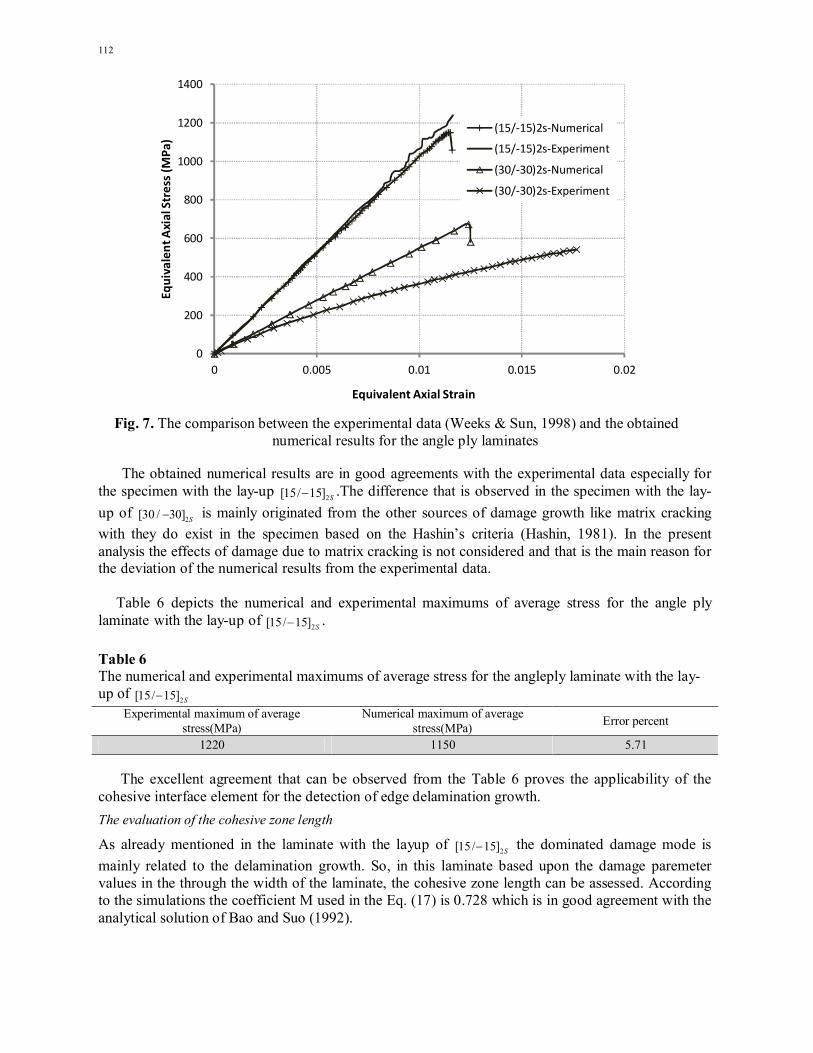
Fig. 9. Profile of the out of plane stresses distribution of the considered cross-ply laminates among the thickness
It is noteworthy to mention that in these laminates due to the lack of consistency in the directional properties in regions where the orientation of the plies are changed may lead to the transverse
stresses. The evolution of the interlaminar stresses like z and yz at the edge of the laminate are
originated as a result of the zero transverse stresses in these regions. According to the Fig. 9 the interlaminar stresses in comparison with the average magnitude of the stress in the transverse direction is considerable. Thus, these stresses increase the potential of the delamination growth in the laminate. It is to be noted that the profile of the interlaminar stresses is consistent with the results available in the literature (Tahani & Nosier, 2004). For the purpose of detecting the damage initiation from the two sources of delamination and matrix cracking in the cross-ply laminates, moreover than Eq. (9) the Hashin’s ply failure criteria(Hashin, 1981) are employed. These criteria are given by:
Tensile Fiber Mode :)0( 1
(����)� +
(���� + ���
� )
��� = 1
Compressive Fiber Mode :)0( 1
������ = 1
)18 (
Tensile Matrix Mode :)0( 32
(�� + ����
)� +(���
� + ���� )
��� +
(���� − ����)
��� = 1
Compressive Matrix Mode :)0( 32
����2����
− 1� (�� + ����
) + (�� + ��2��
)� +(���
� + ���� )
��� +
(���� − ����)
��� = 1
-30
-20
-10
0
10
20
30
0 0.15875 0.3175 0.47625 0.635 0.79375 0.9525 1.11125 1.27
Inte
rlam
ina
r Str
ess
es(M
Pa
)
Distanse from middle plane(mm)
(90/0)2s-Szz
(90/0)2s-Syz
(0/90)2s-Szz
(0/90)2s-Syz
B. Mohammadi and D. Salimi-Majd / Engineering Solid Mechanics 2 (2014)
115
where the subscript 1 denotes the fiber direction and 2, 3 are orthogonal directions in the plane perpendicular to the fiber direction and:
��=Tensile strength in fiber direction, ��=Compressive strength in fiber direction,
��=Tensile strength transverse to fiber direction, ��=Compressive strength transverse to fiber direction, ��=In-plane shear strength, ��=Transverse shear strength
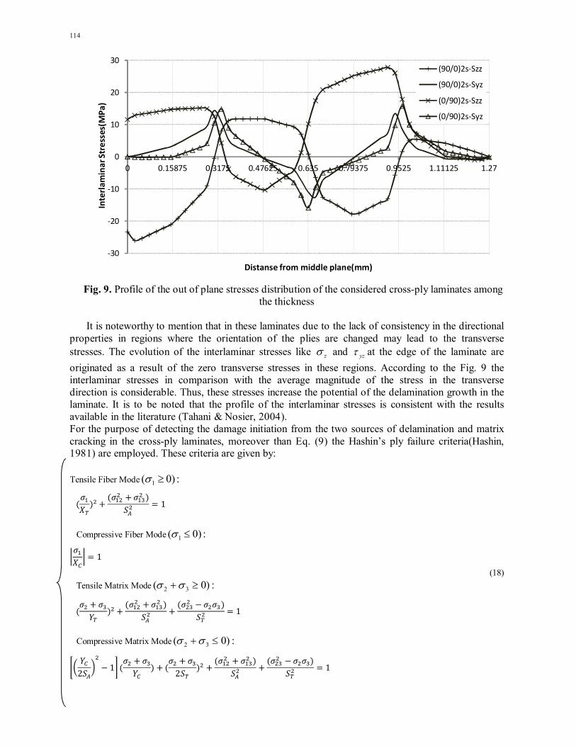
It is to be noted that for the purpose of comparing the effects of stacking sequence in the cross-ply laminates, only the initiation of damage in the within the ply is considered via implementation of the fore mentioned criteria in the ANSYS commercial software. Fig. 10 depicts the matrix failure index and the interlaminar damage initiation parameter for both cross-ply laminates.
Fig. 10. The matrix failure index and the interlaminar damage initiation parameter for cross-ply laminates
In Fig. 10 it can be observed that in both of the considered cross ply laminates the matrix cracking index is considerably higher than the interlaminar damage initiation index which illustrates the importance of matrix cracking in these laminates. The most important observation is that if the plies with the 90 fiber orientations placed at the side of the laminate, delamination initiation and matrix cracking would postpone. It is to be noted that based upon the similar out of plane shear stresses in these two layups the main reason that is able to justify the delay in damage initiation is that for the case with the outer 90 degree layers the out of plane normal stress is compressive at the interface of two adjacent 0 and 90 degree plies where the out of plane shear stress is maximized. In contrast to the previous case, in
S2]90/0[ the out of plane normal stress is tension which may lead to the delamination growth.
0
0.1
0.2
0.3
0.4
0.5
0.6
0.7
0.8
0 0.15875 0.3175 0.47625 0.635 0.79375 0.9525 1.11125 1.27
Dam
age
Init
iati
on
Cri
teri
a
Distanse from middle plane(mm)
Delamination -(90/0)2s
Matrix Failure-(90/0)2s
Delamination -(0/90)2s
Matrix Failure-(0/90)2s

116
Based upon the fact that in the 90 degree plies in comparison with the 0 degree plies due to the higher in-plane normal stress component in the matrix direction, the occurrence of matrix cracking is more expectable. Moreover, it can be observed from Fig. 9 that in both of those lay-ups the out of plane
normal stress z in 90 degree plies is tension while its magnitude for the specimen with the lay-up
S2]90/0[ is higher. So based on the Hashin’s criteria the matrix cracking index in the laminate with
the layup ofS2]90/0[ is higher than the other one, although both of them have the same magnitude of
in-plane normal and shear stresses. It is to be considered that for the out of plane loading conditions like the bending moment, due to the importance of the laminate bending stiffness, the layers with the zero degree plies are placed in the outer region of the laminate.
5. Conclusions
In this study the delamination due to edge effects in the composite laminates with the cross-ply and angle ply lay-ups have been considered. Thus, an interface element based on the cohesive zone model was implemented via the Ansys finite element commercial software package. In addition, Hashin’s failure criteria were used to predict ply damage initiation. The comparison of the obtained numerical results proves the applicability of the interface element for the edge effect delamination growth. In the laminates with cross ply lay-ups, it is observed that the lay-ups play an important role in postponing the matrix cracking and delamination initiation in the in-plane axial tension loading condition. The numerical results depict that using the 90 degree plies in the outer part of the laminate would lead to the delay in delamination initiation and matrix cracking.
Acknowledgement The authors would like to thank the anonymous referees for constructive comments on earlier version of this paper. References Balzani, C., & Wagner, W. (2008). An interface element for the simulation of delamination in
unidirectional fiber-reinforced composite laminates. Engineering Fracture Mechanics, 75(9), 2597-2615.
Bao, G., & Suo, Z. (1992). Remarks on crack-bridging concepts. Applied Mechanics Review, 45, 355–366.
Barenblatt, G. I. (1962). The mathematical theory of equilibrium cracks in brittle fracture. Advances in applied mechanics, 7(1), 55-129.
Bažant, Z. P., & Bažant, Z. P. (1998). Fracture and size effect: in concrete and other quasibrittle materials (Vol. 16). CRC press.
Benzeggagh, M. L., & Kenane, M. (1996). Measurement of mixed-mode delamination fracture toughness of unidirectional glass/epoxy composites with mixed-mode bending apparatus. Composites Science and Technology, 56(4), 439-449.
Camanho, P. P., Davila, C. G., & De Moura, M. F. (2003). Numerical simulation of mixed-mode progressive delamination in composite materials. Journal of composite materials, 37(16), 1415-1438.
Corigliano, A. (1993). Formulation, identification and use of interface models in the numerical analysis of composite delamination. International Journal of Solids and Structures, 30(20), 2779-2811.
Cox, B. N., & Marshall, D. B. (1994). Concepts for bridged cracks in fracture and fatigue. Acta Metallurgica et Materialia, 42(2), 341-363.
B. Mohammadi and D. Salimi-Majd / Engineering Solid Mechanics 2 (2014)
117
Daudeville, L., Allix, O., & Ladeveze, P. (1995). Delamination analysis by damage mechanics: some applications. Composites Engineering, 5(1), 17-24.
Davila, C. G., Camanho, P. P., & Rose, C. A. (2005). Failure criteria for FRP laminates. Journal of Composite materials, 39(4), 323-345.
Dugdale, D. S. (1960). Yielding of steel sheets containing slits. Journal of the Mechanics and Physics of Solids, 8(2), 100-104.
Hashin, Z., (1981). Failure criteria for unidirectional fiber composites, Journal of Applied Mechanics, 20, 329–334.
Hassan, N. M., & Batra, R. C. (2008). Modeling damage in polymeric composites. Composites Part B: Engineering, 39(1), 66-82.
Hessabi, Z. R., Majidi, B., & Aghazadeh, J. (2005). Effects of stacking sequence on fracture mechanisms in quasi-isotropic carbon/epoxy laminates under tensile loading. Iranian Polymer Journal, 14(6), 531-538.
Hillerborg, A., Modéer, M., & Petersson, P. E. (1976). Analysis of crack formation and crack growth in concrete by means of fracture mechanics and finite elements. Cement and concrete research, 6(6), 773-781.
Hosseini-Toudeshky, H., Hosseini, S., & Mohammadi, B. (2010). Buckling and delamination growth analysis of composite laminates containing embedded delaminations. Applied Composite Materials, 17(2), 95-109.
Hui, C. Y., Jagota, A., Bennison, S. J., & Londono, J. D. (2003). Crack blunting and the strength of soft elastic solids. Proceedings of the Royal Society of London. Series A: Mathematical, Physical and Engineering Sciences, 459(2034), 1489-1516.
Irwin, G.R., (1960). Plastic zone near a crack and fracture toughness, Proceedings of the Seventh Sagamore Ordnance Materials Conference, Volume IV, Syracuse University, New York, 63–78.
Lingen, F. J., & Schipperen, J. H. A. (2000). An efficient parallel procedure for the simulation of free edge delamination in composite materials. Computers & Structures, 76(5), 637-649.
Mi, Y., Crisfield, M. A., Davies, G. A. O., & Hellweg, H. B. (1998). Progressive delamination using interface elements. Journal of composite materials, 32(14), 1246-1272.
Pagano, N. J., & Pipes, R. B. (1973). Some observations on the interlaminar strength of composite laminates. International Journal of Mechanical Sciences, 15(8), 679-688.
Tahani, M., & NOSIER, A. (2004). Accurate determination of interlaminar stresses in general cross-ply laminates. Mechanics of Advanced Materials and Structures, 11(1), 67-92.
Mohammadi, B., Hosseini-Toudeshky, H. & Sadr-Lahidjani, M.H. (2008). Progressive damage analyses of angle-ply laminates exhibiting free edge effects using continuum damage mechanics with layer‐wise finite element method. Fatigue & Fracture of Engineering Materials & Structures, 31(7), 549-568.
Naghipour, P., Bartsch, M., Chernova, L., Hausmann, J., & Voggenreiter, H. (2010). Effect of fiber angle orientation and stacking sequence on mixed mode fracture toughness of carbon fiber reinforced plastics: Numerical and experimental investigations. Materials Science and Engineering: A, 527(3), 509-517.
Rice, J. R. (1980). The mechanics of earthquake rupture, Physics of the Earth's Interior AM Dziewonski, E. Boschi, 555–649.
Turon, A., Davila, C. G., Camanho, P. P., & Costa, J. (2007a). An engineering solution for mesh size effects in the simulation of delamination using cohesive zone models. Engineering Fracture Mechanics, 74(10), 1665-1682.
Turon, A., Costa, J., Camanho, P. P., & Dávila, C. G. (2007b). Simulation of delamination in composites under high-cycle fatigue. Composites Part A: applied science and manufacturing, 38(11), 2270-2282.
Turon, A., Costa, J., Camanho, P. P., & Maimí, P. (2008). Analytical and numerical investigation of the length of the cohesive zone in delaminated composite materials. In Mechanical response of composites (pp. 77-97). Springer Netherlands.

118
Weeks, C. A., & Sun, C. T. (1998). Modeling non-linear rate-dependent behavior in fiber-reinforced composites. Composites Science and Technology, 58(3), 603-611.
Xu, X. P., & Needleman, A. (1994). Numerical simulations of fast crack growth in brittle solids. Journal of the Mechanics and Physics of Solids, 42(9), 1397-1434.
Ye, L. (1988). Role of matrix resin in delamination onset and growth in composite laminates. Composites science and technology, 33(4), 257-277.