Embed Size (px)
Citation preview
STATE OF WASHINGTON
DEPARTMENT OF NATURAL RESOURCES
BERT L. COLE, Commissioner of Public Lands
DON LEE FRASER, Supervisor
DIVISION OF GEOLOGY AND EARTH RESOURCES
VAUGHN E. LIVINGSTON, JR., State Geologist
INFORMATION CIRCULAR 58
ENGINEERING GEOLOGIC STUDIES
1976
For sale by Department of Natural Resources, Olympia, Washington.
Price $1.00


9
21
35
CONTENTS
Soil - What is it?
Kurt L. Othberg
The role of ground water in slope stability
Walter D. Paterson
Potential land use problems of Puget Sound shore bluffs
D. W. Mintz, R. S. Babcock, and T. A. Terich
Seismic risk
Ernest R. Artim
III

SOIL-WHAT IS IT?
By
Kurt L. Othberg Department of Natural Resources Division of Geology and Earth Resources Olympia, WA 98504
Department of Natural Resources Division of Geology and Earth Resources
Information Circular 58, Engineering Geologic Studies
1976


3
SOIL-WHAT IS IT?
By
Kurt L. Othberg
Information concerning the physical conditions
of the land is being sought increasing ly for land use
planning. The great majority of that land surface is
composed of earth material, which we a l I refer to as
soil. However, in current usage, especially in reports
and maps prepared for urban planning, the meaning of
"soil" is ambiguous. Unfortunately, many lay people,
and some technical people, are not aware of the dif
ferent meanings . The most serious consequence, in
my opinion, is misinterpretation of "soi I" properties
which are important to urban development. This paper
presents the varied, technical meanings of "soil,"
some suggestions for increasing clarity of usage, and
a discussion of the importance of distinguishing be
tween different "soi Is. "
The physical nature of the land we live on is
studied by geologists, soil scientists (pedologists),
and soil engineers {geotechnical engineers). Each of
these professions is concerned with a different aspect
of the earth's surface. The geologist is concerned,
primarily, with the mapping of rocks and surface de
posits.!/ He emphasizes the origin and age relation
ships of these materia ls and the processes that form or
modify them. Originally, geologists regarded soil as
the unconsolidated sediments overlying rock (Leggett,
1967) . However, during this century, many geologists
have come to restrict their use of the term soi I to the
thin, weotheredv part of rock or surface deposits
1/ Surface deposits are geological ly young sediments, such as al luvium, glacial deposits, landslide debris, etc.
Y Weathering: The mechanical, chemical, and biologica l processes whereby mineral matter on exposure to the weather (wind, water, or ice) changes in character and decoys and crumb I es .
that forms on the surface of the earth, which is the
result of c limatic and biologic processes acting upon
rock or unconsolidated sediment.
Pedologists and agricultural soil scientists
have been primori ly concerned with the mapping of
the uppermost layers, or profi le, of the land surface
in which plants anchor their roots and derive the
nutrients and water necessary for growth . The profile
development varies from place to place, depending
on many factors that control the degree of weathering
and organic accumulation.
As used by the Notional Cooperative Soil Sur
vey, soil "is the co llection of natural bodies on the
earth' s surface, in places modified or even mode by
many of earthy materials, containing living matter,
and supporting or capable of supporting plants out- of
doors. Soi I includes horizons near the surface differ
ing from the underlying rock materia l o.s a result of
interactions among climate, living organisms, parent
materials, and rel ief in combination. In the places
where the soil hos genetic horizons, it is at least as
deep as the horizons that hove evidence of biological
activity in combination with other factors. Where
the soi l locks genetic horizons, it grades at its lower
margin to hard rock or the earthy materials virtually
devoid of roots, animals, or marks of other biologic
activity," (Soi l Survey Staff, 1973). Below soil in
the pedologico l sense lies parent rock or parent mate
rial , which include consolidated igneous, metamorphic,
and sedimentary rocks, as wel I as unconsol idated sur
face deposits.
Engineers have continued to use the word soi I
in the original meaning defined as "sediments or other
unconsolidated accumulations of so lid particles pro
duced by the physical and chemica l disintegration of

4 SO IL- WHAT rs IT?
rocks, and which may or may not contain organic
matter" (American Society for Testing and Mate
rials, 1967). Engineering soil is the combination
of raw, unaltered surface deposits, plus the pedo
logical horizons in which plants root. This is ap
proximately equivalent to regolith, as used by soil
scientists and some geologists to mean all loose
earth materials above solid rock.
To generalize, there are two different tech
nical definitions and usages for the word "soil":
(l) the plant- re lated genetic profile (hereafter refered
to as "agricultural soil"}; and (2) regolith (hereafter
referred to as "engineering soil") . Soil scientists and
surficial geologists use definition (l), soil engineers
(geotechnical engineers) and engineering geologists
use definition (2). Rarely, however, wi II the dis
tinction of usage be explained in a report written by
technical people.
In order to be clearly understood, our usage
of the word soil must be carefully defined, and fur
ther, we must point out to others that the ambiguity
exists. By specifying the actual usage of the term in
existing maps and reports, and by precisely defining
terminology in future maps and reports , applied earth
science can serve the public in a better way.
Some of the ways that earth materials can be
described specifically are as follows:
Earth materials or geo logic materials: The
most general case , from solid rock to a humic A
horizon.
Rock : Consolidated earth materials , sedimen
tary, igneous, and metamorphic in origin .
Surface deposits: Unconsolidated!/ earth
materials deposited or accumulated by geologic agen
cies, and which underlie agricultural soil. Surface
!/ Unconso lidated in the geologic sense rather than the engineering sense; for example, surface deposits such as g lacia I ti II are very compact, but have not been cemented into hard rock.
deposits arbitrari fy begin at the lower limit of agri
cultural soi l.
Agricultural soil: Unconsolidated earth mate
rials comprising that part of the surface of the ground
which has been modified through time by climatic and
biologic agents. Its lower limit is hard rock or min
eral matter devoid of roots or other marks of bio logic
activity .
Engineering soi l or regolith : All unconsoli
dated earth materials. Includes agricultural soil and
surface deposits.
Geotechni cal reports written by soi Is engineers
and engineering geologists will deal with the particle
size, strength, and a number of other factors important
to engineering work. They study soi I at all depths,
depending on need. The need for a light- duty road
way requires study of only a few feet of engineering
soi I. For bui ld ing foundations, the investigation may
go tens of feet deep via bore holes and trenches. The
properties of the more than 3,000 feet of soil underly
ing Seattle may be studied by engineers for earthquake
response in that city . There can be little doubt that
soi l studied by eng ineers is the soil most important to
urban planning.
The U.S. Department of Agriculture Soil Con
servation Service has published a number of reports
with maps of agricultural soi Is. These maps have fre
quently been uti Ii zed for urban planning purposes .
The older reports do not clear ly define soil, and, in
fact, use the term in both senses: "soil (definition l)
is the product of the forces of the environment acting
on the soi I (definition 2) materials deposited or accum
ulated by the geologic agencies" (Glassey and others,
1958). Soil (l) is agricultural soil, soil (2) refers to
surface deposits, or the unweathered part of engineer
ing soi I. Newest reports, such as the Jefferson- County
Soil Survey (McCreary, 1975), define soil in the
glossary_. and avoid the ambiguity by using "parent
material" instead of "soil materials" when referring to
surface deposits .
The modern soi I surveys include interpretations
of engineering properties for urban uses. Detailed,
valuable data is presented for each significant horizon
of the agricultural soil. However, one must not as
sume that the properties con be extrapolated into the
eng ineering soil lying below .
Geologic mops , which ore published by the
U.S. Geological Survey, the Washington Division of
Geology and Earth Resources, and the Washington
Division of Water Resources, vary in the types of
earth materia ls mopped and their intended use . Many
geologic mops show bedrock but either ignore engi
neering soils or commonly lump them together as al
luvium. Surficiol geologic mops show rocks and sed
iments that directly underlie the earth's surface. They
emphasize distinctions between types of sediments and
ore, in effect, mops of surface deposits or that port of
engineering soil that lies below agricultural soil.
Geologic mops hove little or no value for agricultural
purposes. Although surficiol geologic mops deal di
rectly with engineering soils, many, such as the
geology and ground water reports, hove no engineer
ing i nterpretoti ons. However, I and use i nterpretotive
geologic mops ore available through engineering
SOIL-WHAT IS IT? 5
geology consultants, and hove been mode, upon re
quest, by the Washington Division of Geology and
Earth Resources for counties. Land use interpretive
geologic mops present specific engineering soi I and
rock interpretations .
Urban planning requires analysis of land chor
acteri sties so that each land use can have the I east
number of deleterious effects for the land , buildings,
and people. Agricultural soils should be studied so
that the ideal land for crops and timber can be iden
tified. Engineering soils and rocks should be studied
so thc;rt mineral and ground water resources can be
conserved and the effects of geologic hazards such as
landsliding, shoreline erosion, earthquakes, and sub
sidence can be minimized .
As a result of repeated invasions of glaciers,
the Puget Lowland has thick engineering soi Is, with
thin agricultural soils developed in them. In order to
understand the character and distribution of the engi
neering soi Is, and in turn make the best land use
plans, one needs information about both aspects of
engineering soi ls: agricultura l :soils and the underly
ing surface deposits. The best information available
on surface deposits is a surficio l geologic mop.


SELECTED REFERENCES 7
SELEC TED REFERENCES
American Society for Testing and Materi a Is, 1967, Book of A. S. T. M. Standards, Part 2: American Society for Testing and Materials, Philade lphia, p. 298.
Fli nt, R. F., i 971, Glacial and Quaternary geology: John Wiley and Sons, New York, 892 p.
Haynes, Vance, 1973, Soil redefined: Geotimes, v. 18, no. 11,·p. 8.
Hunt, C. B. , 1972, Geology of soils; their evolution, classification , and uses: W. H. Freeman and Co., San Francisco, 344 p.
Gary, Margaret; McAfee, Robert, Jr.; Wolf, C. L., 1972, Glossary of geology: American Geological Institute, Washington, D. C., 805 p. plus 52- page appendix.
Gillott , J . E. , 1968, Clay in engineering geology: Elsevier Publishing Co . , New York, 296 p.
G lassey , T. W. ; and others, 1958, Soil survey of Thurston County, Washington: U.S. Department of Agricu lture Soil Conservation Service, in cooperation with the Washington A9ricultural Experiment Station,, 79 p. plus 35 map sheets.
Leggett, R. F., 1967, Soil- Its geology and use : Geological Society of Amerka Bulletin, v. 78, no. 12, p . 1433- 1456.
Leggett, Robert, 1973, Soil : Geotimes, v. 18, no. 9, p. 38- 39.
McCreary, F. R., )975, Soil survey of Jefferson County area, Washington: U.S. Soil Conservation Service, in cooperation with the Washington Agricultural Experiment Sttation , 100 p., plus 70 map sheets.
Mclerran, J. H., 1954, State of Washington Engineering Soils Manual; Part 1, The Engineer and Pedology: Washington State Council for Highway Research, 56 p.
Millot, Georges, 1970, Geology of clays: Springer- Verlag, New York, 429 p.
Soil Science Society of America, 1973, Glossary of soil science terms: Soil Science Society of America, Madison , Wisconsin , 33 p.
Soi l Survey Staff, 1973, Soil taxomony- A basic system of soil classification for making and interpreting soil surveys [preliminary, abridged text] : U.S. Soil Conservation Service, 330 p.

THE ROLE OF GROUND WATER IN SLOPE STABILITY
By
Walter D. Paterson Consulting geologist 405 Alaska T rode Building Seattle, WA 98101
Deportment of No turo I Resources Division of Geology and Earth Resources
Information Circular 58, Engineering Geologic Studies
1976
9


11
CONTENTS
Introduction • . • . . • . . . . • . . . • . . • . . . . . • . . . . . . . . . . . • . . . . . . . . . . . . . . . . . . . . . . . . . . . . . . 13
Ground water . . . . • . • • . . • . . • . • • • . . • . . • . . . . . . . . . . . . • . . • . . . . . . . . . . • . . . . . . . . . . . . . . 1 3
Effects of ground water on the strength of soi I . . . • . • . . . . . • . . . . . . . . . . . . . . . . . . . 13
Subsurface erosion (piping) . . . . . . . . . . • . • . . . . • . . . • . . . . . . . . . . . . • . • . . • 13
Solution . . . • • . . . • . • . . . . . . . . . . . . . . . . . . . . . . . . . • . . . . . . . . . . . . . . . . . . • 14
Frost • . . . . . • . . . . • . • . . . . . . . . . . . . . . . . . . . . . . . . • . . . . . • . . . . . . . • . . . . . . 14
Surface tension . . . . • . . . . . . . . • . . . . . . . . . . . • . . . . . . . . . . . . . . . . . • . . . . . • 14
Pore pressure • . . . . . . . . . . . . . . . . . . . . . . . . . . . . . . . • . . . . . . . . . . . . • . . . . . . 14
Lubrication . . . . • . • . . • . . . . . . . . . . . . . . . . . . . . . . . . . . . • . . . . . . . . . • . • • . . . 15
Prevention of ground-water- induced slides . . . • . . . . . . . . . . . . . . . . . . . . . . • . . . . . . . 15
Subsurface erosion (piping) . . • • . . . . . • . . • • . • • . . . . . . • . . . . . . . . . • . . . . . . 15
Solution •.. . • • • . . . . • . . • . . . . . . . . . . • . . . . . . . . . . . . • . • . . . . . . . . . • . . . . . . 15
Freezing and thawing . . . . . . . • . . . . . . . . . . . . . • . . • . . . . . . . . . . . . . • . . . . . . 15
Surface tension . . . • • . . • . . . . . . . . . . . • . . . . . . . . . . . . . • . . . . . . . . . . . . . . . . 16
Pore pressure • . . • . • . . . . . . . . . . . . . . . . . . . . . . . . • . . . . . . . . . . . . . . . . . . . . . 1 6
Deep wells . . . . • . . . . . . . . . . . . . . . . . • . . . . • . . . . . . . . . . . . . . . . . . . 16
Large diameter- shallow wells . . . . . . . . . . . . . . . . . . . . . . . . . . . . . . . 16
Wei I points • . . . . . . . . . . . . . . . • • . . . . . • • . . • . . . . . . . . . . . . . . . . . . . 16
Dri 11 ed hori zonta I drains . . . . . • . . . . . . • . • . . • . . . . . . . . . . • . . • • . • . 16
Excavated drains . . . . . . . . . . . . . . . . • • • . . . . . . . • . . . . . . . . . • . . . . • 17
Selected references 19

13
THE ROLE OF GROUND WATER IN SLOPE STABILITY
By
Walter D. Paterson
INTRODUCTION
Slope stability exists as long as the shear
strength !/of the soil ?/exceeds the shearing stresses)/
Any change of conditions that causes the stress to
equal or exceed the strength will result in instability
and probable slope failure, in the form of lands lides,
mudflows, or other mass movements of earth. Increases
in stress, with the exception of those caused by earth
quakes, blasting or other dynamic forces, are gener
ally related to visib le changes, such as erosion, man
made cuts and fills, or bui I ding loads, whereas
decreases in strength are due to internal changes
within the mass of the soil. The most important ele
ment affecting the strength of soil is ground water.
GROUND WATER
Precipitation that reaches the ground either
returns to the atmosphere by evaporation and transpi
ration, runs off through surface streams, or per co I ates
!/ Shear strength is the resistance of a material to deformation or fracture by sliding of one section of the materia I against another section.
?/ Soil is a natural aggregate of mineral groins that con be separated by gentle mechanical means, such as agitation in water (Terzaghi and Peck, 1948).
~ Shearing stress is the force, per unit area of materia I, that tends to cause deformation or fracture by sliding of one section of the material against another.
downward through the soi I. If the quantity of water
is sufficient, downward percolation will continue
unti I either an impermeable barrier or a zone of sat
urated soil is reached.
The upper boundary of the zone of saturated
soi I marks the water table. The zone of saturation
may be supported by an impermeable formation of
limited lateral extent, with incomplete saturation oc
curring below the barrier . The water table in this sit
uation is said to be perched.
EFFECTS OF GROUND WATER
ON THE STRENGTH OF SOIL
The processes by which ground water affects
the stabi Ii ty of soi I ore described below.
Subsurface Erosion (Piping)
A highly permeable formation may develop a
subsurface water flow of sufficient concentration and
velocity to remove the finer grains of soil; this can
result in the formation of narrow conduits or pipes
through which the soil materi al is removed. The
process accelerates as removal of the fine groins
increases the permeability, which in turn increases
the flow of water and causes larger grains to be eroded
from the formation. The limiting factors are the
avai I able supply of ground wafter and the grain-size
distribution within the soi I.
Ultimately, the slopes may slump into ground
water discharge area. Piping has been a problem in
improperly constructed earth dams and reservoir em-
14 GROUND WATER AND SLOPE STABILITY
bankments where, because of the essentially unlimited
water supply, the process may accelerate until failure
of the structure occurs . Any excavation that cuts a
permeable sand and gravel formation could initiate
the piping process, and slumping along slopes may
result if a sufficient supply of ground water is avail
able. Solution
Some granular soils are cemented by chemi
cally precipitated minerals, which are soluble in
water . Removal of the cement may reduce a rela
tively strong formation, capable of standing nearly
vertical, to a cohesionless granular soil that tends to
be unstable in steep slopes. Chemical cements are
rare in the glacia l deposits of the Puget Sound Low
land, and those soils that do contain soluble cement
ing materials are not vulnerable to rapid solution
unless there is a radical change in either the rate of
flow or the acidity of the ground water.
Frost
Freezing and thawing of water in the soil
causes a heaving of the surface. The heaving on
steep slopes results in sloughing and may, over a
period of years, undercut overlying soils, which are
not affected by the freezing. G loci a I til Is!/ are par
ticularly sub i ect to frost action because they are
heterogeneous soils capable of carrying some water,
but they are not free draining. The readily observ
able instabil ity developes slowly so that serious dam
age can generally be prevented .
Surface Tension
Completely dry, clean sand wi II stand at an
angle of repose detemiined by the shape and roughness
!/ Glacial till is a soil deposited directly by glacial ice. In the Puget Lowland, till usually refers to the dense soil deposited under a moving glacier and is commonly referred to as "hardpan."
of the individual grains. The angle is generally less
than 30 degrees. The addition of suffi'cient moisture to
form a fi Im around each grain creates cidded strength
through surface tension; therefore, damp, fine sand
may stand in a vertical bank. As the grain size
increases, the effect of surface tension becomes less.
Sand in freshly exposed slopes is generally
damp, and as drying tokes place, slumping and run
ning of the sand reduces the slope to the angle of re
pose of dry sand. Surface tension may also be des
troyed by increasing the moisture content of a granu
lar soi I to the point of saturation. Saturation implies
the development of pore pressure which is discussed
in detail below.
Pore Pressure
The most common cause of landslides in the
Puget Sound area is the reduction of soi I strength
resulting from an increase in ground-water pressure.
The shear strength of soi I is portly a function of
the internal friction between the grains. The hydro
static pressure of the water in the pore space of the
soil is pore pressure. Increasing the pore pressure
reduces the contact pressures between the groins of
soil; consequently, the internal friction and the shear
strength are reduced. In an extreme case, the entire
weight of overburden may be carried by the pore
water and the shear strength is reduced to nearly zero .
Pore water also increases the stress in soi I by increas
ing the weight. Pore pressure is increased by a rising water
table, which in turn, may be due to any of the fol
lowing events.
1 • An i ncreose in the rate of precipitation.
2. Abnomial accumulations of surface water
through diversion or blockage of surface drainage,
creation of new reservoirs, or raising water levels in
existing reservoirs.
PREVENTION OF GROUND-WATER-INDUCED SLIDES 15
3. Stripping of overburden from more per
meable formations causing an increase in the down
ward perco lotion of ground water.
4. Introduction of water to the soi I through
drain fields or other subsurface structures.
5. Blockage of subsurface drains, springs, or
seeps.
6. Reduction in the rate of pumping from
ground-water reservoirs .
In the Puget Lowland, landslides, caused by
increased pore pressures, are frequently the rotational
type in which shearing occurs along a concave sur
face. In areas where soil formations dip toward a
steep slope, movement may take place along a bed
ding plane.
Movement of a sl ide block tends to relieve the
pore pressure through the re lease of water. If the re
leased water readily escapes from the slide mass, a
more stable condition wi II develop; however, if the
water does not escape, all or part of the disturbed
soi I may become supersaturated and form a mudflow.
Mudflows are potentially the most dangerous of all
earth slides because they may move great distances at
high ve locities over relatively low slopes. Mudflows
are not always secondary effects resulting from block
slides. A mass of loosely packed soil may tend to
absorb preci pi tat ion at a much greater rate than it
wi 11 drain. Once the mass becomes saturated, any
disturbance may reduce the average porosity and pro
duce a supersaturated mixture that will flow as a
liquid. In a like manner, fine soils, known as sensi
tive si Its or clays, have an intergranular structure,
which may be altered when disturbed. The alteration
of the structure rapidly produces the supersaturated
condition required to cause flow.
Lubrication
The lubrication effect of water is often con
sidered to be a major factor in slope stability. Actu-
ally, water content in the soil tends to improve co
hesion in fine- grained materials through the develop
ment of surface tension provided the water does not
reach the saturation point. As the water content
increases to saturation, the internal pare pressure
becomes the dominating influence. Slides, which
move a long a clay layer interbedded between stronger
formations, are in a sense lubri coted by the wet clay.
PREVENTION OF
GROUND-WATER-INDUCED SLIDES
Subsurface Erosion (Piping)
Piping could be controlled by reducing or
eliminating the flow of ground water; however, this is
genera lly less practica l than controlling the flow in
the area of discharge. A cover or blanket of sand
and gravel properly graded on the slope over the area
of ground- water discharge, with the coarser material
on the outside of the blanket, forms an inverted filter
over the discharging water . The blanket reduces the
velocity of flow by increasing the length of the dis
charge path and increasing the area of discharge.
Under no circumstances should the discharge of ground
water be blocked or retarded.
So I uti on
A known source of acidic water might be pre
vented from percolating into the ground; otherwise,
there is no practical way to prevent solution of ce
menting material. Fortunately, the solution process
is rare in the Puget Lowland.
Freezing and Thawing
Slopes, which are subject to sloughing under
freezing and thawing conditions, may be protected by

16 GROUND WATER AND SLOPE STABILITY
a layer of free draining sand or gravel, The permeable
layer is not affected by freezing and at the same time
prevents frost from reaching the underlying soi I. How
ever, the maintenance of a permeable blanket on
a steep slope may be difficult.
Surface Tension
Loss of surface tension, through drying of
fine -grained noncohesive soil, can be prevented or at
least retarded in our cool, humid climate by a cover
of vegetation. Loss of surface tension through satura
tion requires control of ground water as described
below.
Pore Pressure
Landslides caused by excessive pore pressure
can best be prevented by contro ll ing the ground
water. Ground-water leve ls can be lowered by re
ducing the recharge at the source or by removing
water from the aquifer. Lowering of reservoirs and
improvements of surface drainage wi ll reduce re
charge, but these procedures are not often practi ca I .
In most areas, the water table must be lowered by de
watering the a qui fer.
The choice of dewateri ng methods depends on
the characteristics of the aquifer and its relationship
to the surface topography . The methods descri bed
below have been used successfully in the Puget Low
land.
Deep Wells
Deep wells are most effective where the soil
to be dewotered is a port of, or is directly connected
to, a deeper aquifer with good permeability. A
single deep well may be capable of dewatering a
large area . The disadvantage of this system is the
cost of drilling and developing the we ll and the long
period of time required to lower the water table .
Large Diameter- Shallow Wells
A large diameter perforated pipe may be
dropped into a rapidly excavated hole dug by a bucket
auger, backhoe, or similar type of equipment. Gro
vel is packed around the casing. The method is rela
tively inexpensive; however, the hole usua lly cannot
be dug more than a few feet below the water table.
Water pumped from a well may contain sub
stantial quantities of fine sand and silt. This is par
ticularly true for dewotering wel ls, which ore neces
sarily pumped at or near the highest possible rote.
The remova l of fines from the soi I can result in a loss
of bearing strength and settlement in the area imme
diately surrounding the wel I.
Well Points
In soils of low permeability, the effective
radius of we lls may be only a few feet. Well points
ore 1- to 4-inch diameter screens that ore constructed
to be either dri ll ed or driven into the soi l . The spac
ing is usually four to eight feet between centers with
several of the points being connected to a manifold
at the surface. A suction pump is used to pull the
water from the system . The disadvantage of the
system is that it cannot be made to work at depths
greater than about twenty- five feet below the e leva
tion of the pump.
Dri lled Horizontal Drains
Horizontal drains can be dril led into slopes.
They should, if possible, be directed along the most
permeable layers of soi I. Droi ns have the advantage
of not requiring a pump.
Excavated Drains
Excavated drains vary from simple inexpensive
ditches to complex underground ga ll eries. The more
elaborate systems require detoi led knowledge of the
soi I and ground-water conditions.
Al l dewatering systems should include obser
vation wells or piezometers to measure changes in
PORE PRESSURE 17
ground-water levels. The monitoring of the water
levels is necessary to determine the effectiveness of
the system at the site and to indi cote possible effects
on the surrounding area. Lowering of the water table
con result in excessive settlement and damage to
structures founded on compressible organic soils. The
possible damage to existing wells and springs shou ld
also be considered.


SELECTED REFERENCES 19
SELECTED REFERENCES
Eckel, E. 8., editor, 1958, Landslides and engineering practice: National Academy of SciencesNational Research Council Publication 544, 232 p.
Gilluly, James; Waters, A. C.; Woodford, A. 0., 1968, Principles of geology, 3rd edition: W. H. Freeman Co. , San Francisco, 687 p . .
Paige, Sidney, chairman, 1950, Application of geology to engineering practice: Geological Society of America Berkey Volume, 327 p .
Terzaghi , Karl; Peck, R. R., 1948, Soil mechanics in engineering practice: John Wiley and ,Sons, New York, 566 p.
Zaruba, Quido; Mencl, Vojtech, 1969, Landslides and their control: Elsevier Publishing Co., New York, 205 p.


POTENTIAL LAND USE PROBLEMS Of PUGET SOUND SHORE BLUFFS
By
D. W. Mintz Department of Geography
and Regional Planning
R. S. Babcock Department of Geology
T. A. Terich Department of Geography
and Regional Planning
Western Washington State College Bellingham, WA 98225
Department of Natural Resources Division of Geology and Earth Resources
Information Circular 58, Engineering Geologic Studies
1976
21


23
CONTENTS
Introduction • . • • • • . • • • • • • • . • • . • • • • • • . . • . . . . . . . . • . . • . • • • . . . . . . . • • . . . . . • . . • • . . . . 25
Materials and processes • • . . . • • . • . • • • . . . . . . . . . . . • . . • • • • • • • . • • . • • . . . . . . . . . . . • • . . . . 25
Bluff materials . . . • • • . • • . • . • • • . • • . . . . . • . . • . . • . . • . • • . . . . . . • . . • . . . . . . . • . . . . 25
Mass movement processes . • • • • . • • • • . . . . . • . . . • • • . • . . • . • . . . • • • . . . . . . • . . . • . . . 26
Effects of waves on beaches and bluffs • • . • • • . . . • • • . . • • . • . • . . . . . • . . • . . • . . • . . • • . . . . . 28
Overview • • . • . . • . . . • • . . • . • • . • • • • • • • • • . • . . . . . • • . • • • • • . • • . • • . . . . • . . . . . . • . . . . . . . 29
Erosion processes . • . . • • . • • • • . . • . . . . . . . • . • . . • • . • • . • • . • • . . . . • . . . • . . • . . • • . . • 29
Preparation of building site • • . . • . • . • • • . • . • • . • • • • • . . . • . . . . • . . . . . • . • • • • . • . . • 30
Selected references • . . • • . • • • • • . • • . . . . . • • . • • • • • • . • • . • . . • . . . . . . . . • • . . . . . . . 33
ILLUSTRATIONS
Figure l. Characteristics of several types of mass movement . . • . • • . • • . . • . . . • . . . . . . . . 27
2. Undercutting by wave attack. Establishing construction date may give one the rate of bluff retreat • . • . . . . . . . • . . • . . . . • . • . . • . . . • . . . . 28
3. Bluff slump scar . . .. . .. . .. ... . . . . • . . . . . . . • . . . . . . . . . . • • . • . . . . . . . . . . • . . . 30
4. Effects of soi I creep . • • • • • . . . . . . . . . . . . • . . . . • . . . . . . . . . . . . . . . . • . . . . . . • . . 30
5 . Effects of seawall failure . • . . • . . . . . • • • • . . . . . . . . • . . . . . • . . . . . . . . . . . • . . . . 31
6 . Seawall subjected to wave attack and breaching from side; slumping . . . . . . • . 31


POTENTIAL LAND USE PROBLEMS OF PUGET SOUND SHORE BLUFFS
By
D. W. Mintz, R. S. Babcock, and T .A. Teri ch
INTRODUCTION
Cities and counties adjacent to Puget Sound
now account for 65 percent of the state's population.
Not surprisingly, a great number of residential homes
and summer cottages have been bui It on or near the
shore. The desirabi lity of doing this is quite under
standable: the esthetic enjoyment of water and moun
tain views; beach recreational opportunities; and, in
some circles, an increased social prestige.
A shifting state population, rising personal
income, and a diminishing amount of per-capita shore
line have had the effect of increasing the economic
value of waterfront property'. Relative to prices paid
for other residential property, waterfront lots may be
five to e ight times more expensive. Because of the
high do llar costs invo lved in acquiring waterfront
property, people may understandably want to ensure
that precautions are taken so their investment is not
devalued, damaged, or lost because of geologic
hazards.
This paper is presented as a guide to under
standing the natural geologic processes that affect
banks along the shoreline in Puget Sound. Such know
ledge should al low landowners and land use planners
to assess conditions affecting shoreline property and to
take measures that would alleviate any potentially
destructive situation. Most of the examples in this
report have been drawn from Fidalgo Island in Skagit
County; however, it is believed that the geologic
characteristics of the island and the nature I shore Ii ne
processes operating there are similar to those found
throughout the Puget Sound area.
Real estate agents generally subdivide .shore
line property into three categories: (1) high bank,
(2) low bank, and (3) no bank waterfront. Although
the last two categories are probably the most desirable,
most of the Puget Sound shoreli ne is characterized by
bluffs, with banks varying from several feet to more
than 400 feet high. Thus, the discussion in this paper
wi 11 center on the processes that operate through time
to erode and degrade these higher bluffs. A knowledge
of such processes may be important, not only to main
tain property values but to protect human safety as
well.
MATERIALS AND PROCESSES
BLUFF MATERIALS
Materials making up bluffs along the shoreline
in the Puget Sound can be subdivided as follows:
Bedrock: So lid, jointed or fractured rock.
Clay-silt: Very fine particles deposited by
glacial melt water in former river deltas
and lake bottoms farthest from the source
area {distal deposit).
Glacial till: Mixture of rock fragments
embedded in a fine-grained matrix; com
monly coiled boulder-day or hardpan .
Outwash: Wei I-sorted layers of gravel,
sand, or finer sediments deposited by
glacial melt water, near the source area
{proximal deposit).
Although bedrock sea cliffs are common in
San Juan, Whatcom, and Skagit Counties, most of
the Puget Sound shoreline consists of glacial till, out-
26 POTENTIAL LAND USE PROBLEMS OF PUGET SOUND SHORE BLUFFS
wash, clay-sil t, and nonglacial clay-silt, or a com
posite of these. These materials were deposited during
the last episodes of continental glociation in this
region, approximately 10,000 to 50,000 years or more
ago. Unless a great deal of fracturing and(or) exten
sive weathering has occurred, bedrock sea cliffs rep
resent much less of a stability problem than glacial
deposits. In particular, outwash sand and gravel and
the clay-silts are generally poorly to moderately com
pacted, and thus are highly susceptib le to wave ero
sion and mass movement. The physical nature of
glacial ti ll s is highly variable, but most units are
relatively wel l compacted and therefore more stable.
The engineering properties of bank materials,
such as shear strength, permeabil ity, or bearing capac
ity, may also place constraints on shoreline develop
ment. A good example is the so - called "quick-clay,"
which is commonly of glacial origin. The structure of
this material is thought to resemble a "honeycomb"
that retains large amounts of moisture without loss of
cohesion. However, if the honeycomb structure is
destroyed by ground vibrations, the quick-clay imme
diately converts to a liquid, which will flow if o
slope is present. The devastation in the Turnagai n
Heights section of Anchorage during the 1964 Alaska
earthquake is believed to be the result of such a
quick-clay collapse.
MASS MOVEMENT PROCESSES
Besides the erosional effects of breaking waves
or the runoff of surface water, shoreline bluffs are
also subjected to the movement of materials down
slope, under the influence of gravity. Such gravita
tional transport is generally called mass movement.
Figure 1 shows the characteristics of several types of
mass movement, subdivided according to the speed of
motion involved.
Many bluffs that are quite stable when dry
become highly susceptib le to mass movement when
enough water is present to lubricate slide surfaces or
to produce a semi liquid mass from poorly compacted
sediments. Thus, it is not surprising that many slope
failures occur during or just after periods of heavy
rain. Also, if water is present in bluff materials dur
ing a freeze-thaw cycle, the growth and melting of
of ice crystals may have a considerable effect on
slope stability.
Many bluffs in the Puget Sound region can be
considered to be in a delicate state of balance with
gravity. When this balance is disturbed by man or
nature, mass movement may result. There are at least
four categories of such disturbances,
Undercutting removes the toe support
of a bluff. This is most commonly due to wave
erosion, but manmade excavations can have
the same effect.
Overloading the top of the bluff can
have the same result as undercutting the lower
toe-section.. Thus, considerable care must be
exercised in locating structures or landfi II
relative to the bluff's upper edge.
Saturating bluff materials enhances
instability, either by reducing cohesion or by
increasing load due to the water's weight.
Water is often inadvertently introduced by
septic tonk drain fields, by watering lawns,
or by leaking water mains and sewers.
Vibration from earthquakes, blasting
or heavy equipment operation may cause a
loss of cohesion in bluff materials, resulting
in mass movement.

PROCESSES
CREEP
FALL
MASS MOVEMENT PROCESSES 27
CHARACTERISTICS
Imperceptibly slow downslope gliding of unconsolidated
soil or rock. The movement may involve a particle
by-particle transfer or slow distortion of a larger
mass of surficial material .
Extremely rapid movement of consolidated or uncon
solidated material downward in a vertical or near
vertical path.
PLANAR SLIDE
SLUMP
FLOW
Imperceptible to rapid movement of either consolidated
or unconsolidated material along inclined surfaces
defined by fractures or bedding planes. Introduc
tion of water may facilitate movement either by
increasing load or by lubricating slip planes .
Similar to planar slides except that movement occurs
along internal slip surfaces, which are generally
concave upward.
Viscous downslope movement of distinctly bounded
masses of unconsolidated surficial materia I. Rates
of movement vary from a few feet per hour to sev
era I feet per second depending upon type of mate
rial, slope, water content, vegetation and other
factors .
FIGURE 1.-Characteristics of several types of mass movement (modified from Longwell and others).

28 POTENTIAL LAND USE PROBLEMS OF PUGET SOUND SHORE BLUFFS
EFFECTS OF WAVES ON
BEACHES AND BLUFFS
Wave attack is an important facet of the
erosion-deposition cycle on the beach and bluff back
shore. Waves erode the bluff by undercutting, and
then transport the eroded material one way or another
along the beach. The severity of erosion potential by
waves can be understood when one briefly examines
the origin, mechanisms, and processes of waves.
Waves are generated by wind blowing over the
water. In genera I, the largest waves are generated
by continuous high-wind velocities over a long, large
body of deep water. The open-water di stance over
which wind blows is known as fetch . Because of the
relatively short fetches and shallow waters in Puget
Sound, maximum wave heights seldom excP.ed 4 to 5
feet. Because waves are generated by w incl, the
larger waves occur during the winter storms when
wind speeds are correspondingly highest. If a storm
should coincide with a high tide, waves will be able
to attack at the upper reaches of the beach with more
severity. Figure 2 i 11 ustrates the effects of a com bi-
FIGURE 2.-Undercutting by wave attack. Establishing construction date may give one the rate of bluff retreat.
nation of high tide and relatively large waves working
together to erode a bluff. In this case, however, the
maximum wave heights were under two feet.
Waves are measured not only in terms of height,
but also length and period. Wave length is the hori
zontal distance between two wave crests. Period is
the time lapse between successive wave crests passing
a fixed point. Wave period may either be expressed
in terms of seconds, as the lapse time between two
successive wave crests, or in terms of the number of
crests passing a fixed point in one minute. Wave
period is important, for given the same wave height,
different wave periods cause different effects on a
beach. Longer period waves on the order of 6 to 7
per minute tend to be "constructive" to a beach.
These wave periods bu i Id up, or prograde the beach.
Short period, steep waves, on the order of 12 to 14
per minute, are "destructive" and erode the beach .
This erosion is due to increased, more continuous
wave turbulence keeping material in suspension, and
an increased volume of wave swash and backwash mov
ing on the beach . Because of the short wind fetches
in the Puget Sound, storm-driven wind waves have a
short period and are very erosive. If high tides occur
during a storm, then the effect of these waves wi 11
reach farther up the backshore.
The highly irregular nature of Puget Sound's
shoreline, with its numerous i'slands, bays, and head
lands, presents a variety of wind and wave exposures.
Generally, those beaches and bluffs exposed to the
relatively long fetches to the southwest, south, and
southeast are most susceptible to intense wave attack
from winter storms. On the other hand, beaches and
bluffs with west, northwest and north exposures on the
leeward side of the predominant storm direction are
less likely to experience severe wave attack.
If one examines a beach in the summer and
returns to it again in the winter, he might wel I wonder
_if it is indeed the same beach. The change in the
physical nature of the beach is primarily the result of
seasona I differences in wave attack. Th is difference
is found in wave period, length, height, and di rec-
tion. The small wave heights and longer period waves
of summer drive sand onshore and bui Id up the beach.
The broad, gently inclining sand beach will extend
from the surf up to a bluff or vegetation zone of the
backshore . However, the higher, steeper and shorte r
period waves of winter quickly change the beach pro
file. Winter waves remove the sand accumulated in
summer, and transport it either to deeper water or to
another section of the beach. The result is that the
winter beach is usually narrower, steeper, and rockier;
quite different from the summer beach. The winter
beach thus provides less of a natural buffer to incom
ing waves. This phenomenon, like the effect of high
tide, enhances the impact of storm waves on the toe of
a bluff .
Wave attack erodes beach-front property by
three mechanisms.
1. Chemical-solution: The weather
ing action of the sea water dissolving intra
granular banding materials and carrying them
away in solution.
2 . Hydraulic plucking: Caused by
water compressing air so that pressure of several
thousands of pounds per square inch is bashing
the erosional surface . Th is high pressure breaks
apart a lmost any material- concrete included .
3. Wave~: The result of material,
such as sand and pebbles, abrading the ero
siona I surface, much I ike a sand-blasting
machine.
Resistance to erosion varies according to the
geologic composition of the bluff. For example, the
erosion of exposed bedrock cliffs (such as Chuckanut
Drive in Whatcom County) is considerably less than
that eroded from parts of the western side of Fidalgo
Island, which are composed of poorly compacted
gravel, sand, and clay-sifts.
After material has been eroded by wave attack,
it is removed from the beach by shore drift. Shore
EROSION PROCESSES 29
drift is the h.rm that describes both the material car
ried along by waves on the beach, known as beach
drift, and that carried by currents close to the shore,
known as longshore drift . Once again, the rapidity
and quantity of sediment movement on a beach is a
function of the periods of incoming waves, their steep
ness and direction relative to the shore I ine. Greater
amounts of material tend to be moved when large
waves with short periods (close together) and steep
sides approach the beach at an angle of 45°. Because
of shore drift, extreme care must be exercised when
building jetties, docks, or seawalls. These structures
will impede or stop shore drift causing the beaches to
the lee side to be "starved" of beach material, and
thus hasten bluff erosion because the beach buffer
hos been removed or lessened.
OVERVIEW
The understanding of bluff and beach processes
is academic unless this knowledge can be applied in a
functional way. Therefore, this unit discusses the
general principles to keep in mind when acquiring
water- front property and preparing it for house con
struction.
EROSION PROCESSES
First of all, an initial walk-around at the site
can provide a great dea l of infonmation about active
erosion processes and rotes. Some features to look for
ore listed below:
Bluff materials: Is the bluff composed
of bedrock, ti II, outwash, clay-silt, or a
complex mixture of each? ff the bluff is com
posed of different layers of material, is one
obvious ly weaker than the others?
Bluff undercutting: Scour marks by
wave attack; note where the high tide and
storm waves have driven beach material and
driftwood.

30 POTENTIAL LAND USE PROBLEMS OF PUGET SOUND SHORE BLUFFS
Debris flows: An unconsolidated mix
ture of bank materia I, vegetation, and water,
with on irregular "oozed" appearance.
f.icnmade structures: Do any structures,
such as bulkheads or steps, indicate that the
shoreline is eroded? Are there any structures
on either side of the property that cause the
beach to be "starved" or void of sand and
grovel? Figure 2 obviously indicates rapid
bluff retreat. Shore drift: Is the beach profile steep,
indicating short-period, erosive waves? Is
there an obvious direction of shore drift?
What is the di re ct ion and length of fetch?
Slumping: Cracks in earth or terraces
parallel to the bluff's edge; slump scars on
face of bluff (fig . 3).
FIGURE 3.-Bluff slump scar.
Soil creep: Trees tilted downslope;
overturning and tension crocks in retain-
ing walls; especially note highly susceptible
areas that have been disturbed by excavation
or the dumping of fill. Figure 4 illustrates
how soil creep hos displaced a seawall.
Surface runoff: Look for ri I ls or chan
nels on top of the bluff or on the bluff face,
plus small deltas and alluvial fans formed at
the ba~e of the bluff.
FIGURE 4.-Effects of soil creep.
Vegetation: Note whether vegetation
hos controlled surface runoff and stabi I ized
the bank.
PREPARATION OF BUILDING SITE
After this walk-around, you will then have an
idea of what natural processes are most active or that
have the potential to erode the bluff. When preparing
the site for building, the objective is to minimize and
control activities that will increase the natural mass
movement processes already at work.
Disturb the vegetation and natural
slope~ little OS eossible
The removal of vegetation or major re
grading often results in a drastic change
in surface runoff and the ground-water table.
Such changes may result in the bluff establish
ing a new equilibrium with attendant slump
ing, flows, and surface gullying . The bluff's
adjustment to this change can last for several
years.
Ground cover should be introduced if
passible £!! .9.!.! exeosed, ~ earth
This includes exposed faces of the bluff.
Common bank ivy as well as a host of other
plants help to prevent surface erosion. Consult
your local county extension agent or nursery
for specific recommendations .
Take~ in depositing£.!.!.! material
If possible, excess excavation fi II
should be removed from the site rather than
used for "leveling out" the lot. Fill removal
decreases the load on the bluff, and also de
creases the amount of unconsolidated materia I
that is most vulnerable to creep and flow. Fill
material should not be dumped over the bluff
as this material may alter the natural vegeta
tion, drainage, and compoction of the bluff
face .
.!£ the bluff~ being undercut~~
attack, shore defense structures may be the
only recourse
Breakwaters, seawalls and riprap are
commonly used but considerable care must be
taken to assure that such structures do not
upset the natural shoreline equilibrium. Also,
all structures must be periodically inspected
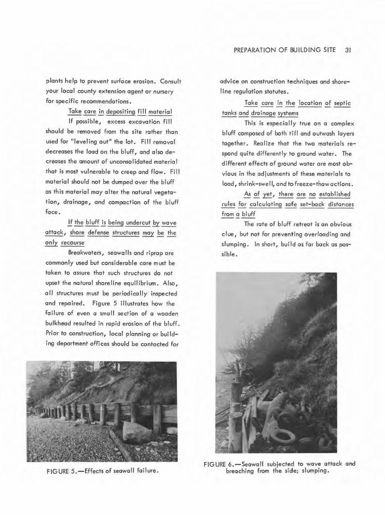
and repaired . Figure 5 illustrates how the
failure of even a small section of a wooden
bulkhead resulted in rapid erosion of the bluff.
Prior to constructio,:i, local planning or bui Id
ing department offices should be contacted for
FIGURE 5.-Effects of seawall failure.
PREPARATION OF BUILDING SITE 31
advice on construction techniques and shore
line regulation statutes.
Take ~ in the location of septic
tanks and drainage systems
This is especially true on a complex
bluff composed of both ti ll and outwash layers
together. Rea I ize that the two materials re
spond quite differently to ground water. The
different effects of ground water ore most ob
vious in the adjustments of these materials to
load, shrink- swell, and to freeze-thaw actions.
As of~, there ~ no established
rules for calculating safe set-bock distances
from a bluff
The rote of bluff retreat is an obvious
clue, but not for preventing overloading and
slumping . In short, build as far bock as pos
sible.
FIGURE 6,-Seawoll subjected to wave attack and breaching from the side; slumping .

32 POTENTIAL LAND USE PROBLEMS OF PUGET SOUND SHORE BLUFFS
Finally, the bluff protection measures
taken El~~ may be effectively ne
gated El the neglect of another owner
Slumps, local water tables, and wave
attack do not respect property I ines. There
fore, collective action is often required of
adjacent landowners . For example, a struc
turally sound and well designed seawall con
be rendered useless by wave attack working on
the next lot. Figure 6 i II ustrates how a
wooden seawall has been breached from the
side. In this case, slumping also resulted from
undercutting. Again, prior to any collective
action, consult with your local building or
planning department.
If any of the previously described conditions
exist on a site or if stability or other geologic problem
is evident or suspected, contact on engineering geol
ogist . In most coses a detailed engineering and
geology report is recommended for individual site
evaluations and investigations.

SELECTED REFERENCES 3;3
SELECTED REFERENCES
Recent Geologic History of Puget Sound
Easterbrook, D. J., 1969, Pleistocene chronology of the Puget Lowland and Son Juan Islands, Washington: Geological Society of America Bulletin, v. 80, no. 11, p. 2273-2286 .
McKee, Bates, 1972, Coscodio: McGraw-Hill Book Co., New York, 394p.
Bluff Processes
Flown, P. T., 1970., Environmental geology-Conservation, land-use planning, and resources management: Harper and Row, New York, 313 p. (especially note chapter 2).
Legget, P. T., 1962, Geology and engineering, 2nd edition: McGraw-Hill Book Co., New York, 884 p. (especially note chapter 11).
Longwell, C . R.; Flint, R. F.; Sanders, J. E., 1969, Physical geology: John Wiley and Sons, New. York, 685 p.
Paige, Sidney, chairman, 1950, Application of geology to engineering practice: Geological Society of America Berkey Volume 327 p. (see chapter by K. Terzaghi on mechanism of landslides).
Beach and Wove Processes
Bascom, Willard, 1964, Waves and beaches-The dynamics of the ocean surface: Doubleday and Co., Gorden City, New York, 267 p.
King, C. A. M . , 1960, Beaches and coasts: E. Arnold, London, 403 p .
Shepard, F. P.; Wanless, H. R. , 1971, Our changing coastline: McGraw-Hill Book Co., New York, 579 p.
Wiegel, R. L., 1964, Oceanogrophical engineering: Prentice-Hall, Englewood Cliffs, New Jersey, 532 p.


SEISMIC RISK
By
Ernest R. Artim Department of Natura I Resources Division of Geology and Earth Resources Olympia, WA 98504
Department of Natural Resources Division of Geology and Earth Resources
Information Circular 58, Engineering Geologic Studies
1976
35


37
SEISMIC RISK
By
Ernest R. Artim
Seismic risk is defined as any risk associated
with earthquakes. Seismic risk can be further defined
as the likelihood of damage or injury from an earth
quake within a given time interval. This time interval
is called a design period for engineering structures, or
it can be an arbitrary interval, such as the next 50 or
120 years . Some of the natural factors included in
seismic risk determination are ground rupture, ground
shaking, landslides caused by the earthquake, earth
"lurches," differential settlement or land subsidence,
liquefaction, tsunamis, and seiches. Seismic risk
determination also includes human factors, such as
dam , reservoir, or any other possible structural fail
ures, emergency services, and public utilities .
The basic objective of planning related to
acceptable seismic risk is to reduce the loss of life,
injuries, and property damages resulting from seismic
activity to an "acceptable" level. Since it is not
possible, or practical, to el iminate all seismic risk to
life and property, each community or region must
decide what level of risk is acceptable for its goals.
Acceptable risk can be defined as follows:
The level of risk below w.hich no
specific action by local government is
deemed to be necessary to protect life and
property.
Because risk is a function of chance, there is
on inherent degree of uncertainty in using risk as
a basis for land use planning. However, land use
planning decisions can be made if the risks ore identi
fied that may arise from potential geologic hazards,
which are associated with any proposed or existing
development, program, or structure, and compared
with alternative risks. If risk reduction measures are
enacted and enforced, the amount of damage to
property and injury to life wi II be reduced over a
given period of time. In th is respect, risk can be a
framework for land use decision making.
Every seismic hazard has on associated element
of risk. This risk hos two aspects: one is the chance
that the hazard wi II in fact occur; and the other
aspect is that, if the hazard does occur, the measures
taken to alleviate the hazard wi II be sufficient to
reduce the damage to life and property to some prede
termined acceptable level. Unfortunately, at the
present time, there are no available technological
methods or capabi Ii ties to control or reduce the actual
occurrence of seismic hazards . Ground shaking can
not be prevented, but its effects con be minimized;
and tsunamis cannot be stopped from reaching coastal
areas, but wise land use planning can reduce the ex
posure of life and property to the hazard.
In addition, although seismic hazards can be
identified, at present the prediction of exactly when
a given event wi II occur cannot be made with any
significant degree of accuracy . The risk of occurrence
of a seismic event is not necessarily a suitable basis
for determining acceptable risk. In other words, it
would not necessori ly be "acceptable" to expose a
school building with a 50-yeor life expectancy to a
potentially destructive seismic hazard with a once
in-500-yeors activity expectancy (assuming no other
hazards were present). The time of the actual seismic
event would be only theoretical with prediction based
38 SEISMIC RISK
on past activity; the actual seismic hazard could, in
fact, occur tomorrow , next week, next year, or in a
thousand years.
The most reasonable basis for determining ac
ceptable risk is whether the preventive measures
taken to reduce the damage to life and property will
result in predetermined acceptab le levels of damage .
Each local jurisdiction should determ ine its own par
ticular acceptable risk levels, based on local land
uses and building types, and on local geo logic condi
tions . However, there are some general guide lines
that should prove helpful for local jurisdictions in
determining acceptable levels of risk .
Emergency services and public utili ties ere
required to provide vital services, especially during
disasters, and seism ic risk should be minimal. These
emergency services and pub lic utilities include the
following:
1. Emergency facilities (hospitals, medica l
clinics, fire and pol ice stations, post-earthquake aid
stations, etc.).
2. Utilities (power plcnts, .water and sewage
facil ities, gas storage tanks, telephone lines, e lectri
cal lines, natural gas lines, etc.).
3 . Communication and transportation systems
(such as telephone terminals, majo r highways, bridges,
tunnels, overpasses and interchanges, railway stations,
ferry terminals, evacuation routes, ~tc.).
4. Water retention structures (such as dams,
reservoirs, etc., used for water storage) .
There should be an exp I icit differentiation be
tween the risk associated with voluntary presence and
the risk associated with involuntary presence. Certain
types of public and private bui ldings and land uses
involve involuntary use, and there is no choice avail
able to the individual whether or not to submit to a
given level of risk . Thus, the level of acceptable
risk in these instances should be qui te low. Public
and private buildings and land uses requiring involun
tary occupancy include nursing homes, convalescent
homes, mental hospita ls, schools, jails, etc .
There should be an expl icit differentiation
between the risk associated with buildings of high
occupancy rates and buildings associated with low
occupancy rotes. All other factors being equal, a
high occupancy building (office bui lding, for example)
will expose many more people to a given seismic
hazard than a low occupancy bui I ding (warehouse
building, for example). Therefore, high occupancy
buildings and land uses should be requi red to have
a risk exposure less than those of low occupancy.
Occupancy rates can be determined by multi
plying the average number of persons exposed by the
average number of hours exposed during some selected
period of time, and dividing that product by the num
ber of hours in the period of computation selected.
Therefore :
Or= Occupancy rate
Pe= Average number of persons exposed
Te= Average number of hours exposed during
some se lected period of time
Ts= Tota l number of hours in the period of
computation selected
Or= Pe x Te
Ts
Exposed persons would include all those within the
building, as well as those outside, that would be
reasonably endangered if the lbui lding were to experi
ence a major structural failure during seismic activity.
For comparison, the fol lowing three samples ore
presented:
A single fami ly dwellrng with four occuponts
hos an average of 2.8 persons (Pe) during a 24- hour
period (Ts). The average number of hours of exposure
is 15.75·hours (Te).

Or= 2.8 x 15.75 = 44.1 = 1.84
24 24
An apartment building contains 400 occupants.
The average number of persons in that apartment dur
ing a 24-hour period (Ts) is 200 (Pe) . The average
numberofhoursofexposure is 12hours (Te).
Or= 200 x 1 2 = 2400 = 1 00
24 24
A sports arena holds 10,000 persons. The
average number of persons in that arena during a 24-
hour period (Ts) is 1,250 (Pe). The average number
of hours of exposure is 3 hours (Te).
Or= 1250 x 3 = 3750 = 156
24 24
No loca I j uri sdi ctions have as yet used occu
pancy rates as o measure of acceptable seismic risk .
Thus, there are no quantitative measures of high,
moderate, and low occupancy rates. However, in
general, high occupancy rates do tend to be asso
ciated with certain kinds of buildings and land uses,
inc luding theaters, churches, forge industrial and
shopping centers, libraries, forge motels and hotels,
restaurants, large office bui ldings, etc .
The level of acceptable risk must be reason
able in terms of the cost of its achievement. Min
imizing risk often results i n higher costs, but at some
balancing point a risk becomes acceptable. At this
point, the pub lic is no longer will ing to pay to reduce
the risk further. The cost need not be di rect (poten
tial damage to property or loss of life), but may be
i ndirect (foregoi ng some projected future economic
benefit by retaining the land in open space, if the
potentia l for seismic risk is high).
Although each local jurisdiction must deter
mine its own priorities in terms of how much it is will
ing to spend to reduce existing and potentia l seismic
risks, two factors should be considered in evaluating
SEISMIC RISK 39
the oost of achieving an acceptable level of risk:
1. The reduction of risk associated with the
human element should be given highest priority. At
o minimum, the risk of injury and loss of life due to
seismic hazards should be no greater than the risk
of injury or loss of life due to disease or due to acci
dents.
2. The level of risk with regard to property
damage should be considered acceptable only if the
potential damage, i n monetary terms, is less than or
equal to the cost of the measure·s proposed to be tal<en
to mitigate the hazard (assuming that the risks to
human life are satisfied) . In other words, if an earth
quake cou ld cause $1 mi I lion worth of damage to
existing structures, and a structura l improvement pro
gram wou ld cost only $500,000, then the cost of the
earthquake risk would not be acceptable and the struc
tura l improvement program would be an acceptable
cost.
The determination of acceptable risk is appli
cable not only to future planning decisions but also to
the evaluation of .the risks associated with existing
buildings and land uses . High risks may be lowered
to a level of acceptable risk by means of physical
alteration (a structural hazard abatement program),
relocation and(or) demolition of existing structures,
and the change of use of structures (from high to low
occupancy, or involuntary to voluntary presence, for
example). Whatever course of action ·is taken, the
cost of achieving the acceptable level of risk should
be commensurate with the benefits gained.
The evaluation of the seriousness of seismic
hazards and their associated risks are the technical
judgments of professiona ls, based on a limited amount
of information of the natura l physical environment .
Even with a substantial amount of basic data, it would
not be easy to quantify techni ca I judgment and experi -
40 SEISMIC RISK
ence into an easily understood format. Because of
this, the concept of acceptable risk has not tradition
ally played an important, if any, ro le in land use
planning decision making. Generally, a structure is
considered "safe" if it conforms to certain required
standards, and "unsafe" if it does not.
The problem involved in addressing the concept
of acceptable risk is not so much a question of whether
a structure or land use is "safe" but rather "haw safe."
Experts are not necessarily "wrong" if thei r recommen
dations on codes, regulations and risk levels prove to
be insufficient during earthquakes. Their judgments
were based on available information and experience .
Each seismic event that occurs will yield new data
that can be used by the experts in future recommen
dations.
C learly then, the role of the engineer, geol
ogist, planner, or other professional should not be to
determine the level of acceptable risk. It is their
function only to lay out the guidelines that wi II allow
the elected officials who represent the public to make
the fina l decisions .