Embed Size (px)
Citation preview
GEOLOGIC AND SOILS ENGINEERING EXPLORATION
PROPOSED RESIDENCE AND POOL
LOT 3, ARB 1, TRACT 7996
1540 SUMMITRIDGE DRIVE
LOS ANGELES, CALIFORNIA
FOR THOMAS CALUS
IRVINE GEOTECHNICAL, INC. PROJECT NUMBER IC 17188-I
OCTOBER 3, 2018
TABLE OF CONTENTS
EXPLORATION . . . . . . . . . . . . . . . . . . . . . . . . . . . . . . . . . . . . . . . . . . . . . . . . . . . . . 2
RESEARCH - PREVIOUS WORK . . . . . . . . . . . . . . . . . . . . . . . . . . . . . . . . . . . . . . . . . 3
PROPOSED PROJECT . . . . . . . . . . . . . . . . . . . . . . . . . . . . . . . . . . . . . . . . . . . . . . . . 4
SITE DESCRIPTION . . . . . . . . . . . . . . . . . . . . . . . . . . . . . . . . . . . . . . . . . . . . . . . . . 4
GROUNDWATER . . . . . . . . . . . . . . . . . . . . . . . . . . . . . . . . . . . . . . . . . . . . . . . . . . . 5
EARTH MATERIALS . . . . . . . . . . . . . . . . . . . . . . . . . . . . . . . . . . . . . . . . . . . . . . . . . 5Fill . . . . . . . . . . . . . . . . . . . . . . . . . . . . . . . . . . . . . . . . . . . . . . . . . . . . . . . . 5Soil . . . . . . . . . . . . . . . . . . . . . . . . . . . . . . . . . . . . . . . . . . . . . . . . . . . . . . . . 5Bedrock . . . . . . . . . . . . . . . . . . . . . . . . . . . . . . . . . . . . . . . . . . . . . . . . . . . . 6
GEOLOGIC STRUCTURE . . . . . . . . . . . . . . . . . . . . . . . . . . . . . . . . . . . . . . . . . . . . . . 6
GENERAL SEISMIC CONSIDERATIONS . . . . . . . . . . . . . . . . . . . . . . . . . . . . . . . . . . . 6Alquist-Priolo Fault Rupture Hazard Study Zone . . . . . . . . . . . . . . . . . . . . . . . 7Building Code Seismic Coefficients . . . . . . . . . . . . . . . . . . . . . . . . . . . . . . . . 7Seismic Hazards . . . . . . . . . . . . . . . . . . . . . . . . . . . . . . . . . . . . . . . . . . . . . . 8Seismic Hazard Zones . . . . . . . . . . . . . . . . . . . . . . . . . . . . . . . . . . . . . . . . . 9Ground Motion . . . . . . . . . . . . . . . . . . . . . . . . . . . . . . . . . . . . . . . . . . . . . . 10
SLOPE STABILITY . . . . . . . . . . . . . . . . . . . . . . . . . . . . . . . . . . . . . . . . . . . . . . . . . 10Gross Stability . . . . . . . . . . . . . . . . . . . . . . . . . . . . . . . . . . . . . . . . . . . . . . 10Surficial Stability . . . . . . . . . . . . . . . . . . . . . . . . . . . . . . . . . . . . . . . . . . . . . 12
CONCLUSIONS AND RECOMMENDATIONS . . . . . . . . . . . . . . . . . . . . . . . . . . . . . . . 12General Findings . . . . . . . . . . . . . . . . . . . . . . . . . . . . . . . . . . . . . . . . . . . . . 12Geotechnical Issues . . . . . . . . . . . . . . . . . . . . . . . . . . . . . . . . . . . . . . . . . . 13
SITE PREPARATION . . . . . . . . . . . . . . . . . . . . . . . . . . . . . . . . . . . . . . . . . . . . . . . . 14General Grading Specifications . . . . . . . . . . . . . . . . . . . . . . . . . . . . . . . . . . 14Fill Slopes . . . . . . . . . . . . . . . . . . . . . . . . . . . . . . . . . . . . . . . . . . . . . . . . . . 15Cut/Trim Slopes . . . . . . . . . . . . . . . . . . . . . . . . . . . . . . . . . . . . . . . . . . . . . 15Excavation Characteristics . . . . . . . . . . . . . . . . . . . . . . . . . . . . . . . . . . . . . 15
SWIMMING POOL . . . . . . . . . . . . . . . . . . . . . . . . . . . . . . . . . . . . . . . . . . . . . . . . . 16
FOUNDATION DESIGN . . . . . . . . . . . . . . . . . . . . . . . . . . . . . . . . . . . . . . . . . . . . . . 16Spread Footings . . . . . . . . . . . . . . . . . . . . . . . . . . . . . . . . . . . . . . . . . . . . . 16Deepened Foundations - Friction Piles . . . . . . . . . . . . . . . . . . . . . . . . . . . . . 17Soldier Piles . . . . . . . . . . . . . . . . . . . . . . . . . . . . . . . . . . . . . . . . . . . . . . . . 18
145 N. Sierra Madre Blvd., Suite #1 • Pasadena • California • 91107 • Phone: 626-844-6641/Fax: 626-604-0394
October 3, 2018IC 17188-IPage 1
Lateral Design - Isolated Piles and Loading Normal to Row of Piles . . . . . . . 18Lateral Design - Pile Groups or Loading Parallel to Row of Piles . . . . . . . . . 19Passive Pressure Reduction - Stacked Retaining Walls . . . . . . . . . . . . . . . . 20Foundation Settlement . . . . . . . . . . . . . . . . . . . . . . . . . . . . . . . . . . . . . . . . 20Foundation Setback . . . . . . . . . . . . . . . . . . . . . . . . . . . . . . . . . . . . . . . . . . 21Toe of Slope Clearance . . . . . . . . . . . . . . . . . . . . . . . . . . . . . . . . . . . . . . . . 21
RETAINING WALLS . . . . . . . . . . . . . . . . . . . . . . . . . . . . . . . . . . . . . . . . . . . . . . . . 21General Design - Static Loading . . . . . . . . . . . . . . . . . . . . . . . . . . . . . . . . . 21Seismic Surcharge . . . . . . . . . . . . . . . . . . . . . . . . . . . . . . . . . . . . . . . . . . . 22Surcharge Loading . . . . . . . . . . . . . . . . . . . . . . . . . . . . . . . . . . . . . . . . . . . 23Subdrain . . . . . . . . . . . . . . . . . . . . . . . . . . . . . . . . . . . . . . . . . . . . . . . . . . . 23Backfill . . . . . . . . . . . . . . . . . . . . . . . . . . . . . . . . . . . . . . . . . . . . . . . . . . . . 24Foundation Design . . . . . . . . . . . . . . . . . . . . . . . . . . . . . . . . . . . . . . . . . . . 24Freeboard . . . . . . . . . . . . . . . . . . . . . . . . . . . . . . . . . . . . . . . . . . . . . . . . . . 24
TEMPORARY EXCAVATIONS . . . . . . . . . . . . . . . . . . . . . . . . . . . . . . . . . . . . . . . . . . 24Shoring . . . . . . . . . . . . . . . . . . . . . . . . . . . . . . . . . . . . . . . . . . . . . . . . . . . . 26Dead Men . . . . . . . . . . . . . . . . . . . . . . . . . . . . . . . . . . . . . . . . . . . . . . . . . 28Surcharge Loading . . . . . . . . . . . . . . . . . . . . . . . . . . . . . . . . . . . . . . . . . . . 29
CORROSION . . . . . . . . . . . . . . . . . . . . . . . . . . . . . . . . . . . . . . . . . . . . . . . . . . . . . 29
FLOOR SLABS & CONCRETE DECKING . . . . . . . . . . . . . . . . . . . . . . . . . . . . . . . . . . 29
DRAINAGE . . . . . . . . . . . . . . . . . . . . . . . . . . . . . . . . . . . . . . . . . . . . . . . . . . . . . . . 31Infiltration . . . . . . . . . . . . . . . . . . . . . . . . . . . . . . . . . . . . . . . . . . . . . . . . . . 32
WATERPROOFING . . . . . . . . . . . . . . . . . . . . . . . . . . . . . . . . . . . . . . . . . . . . . . . . . 32
SITE OBSERVATIONS DURING CONSTRUCTION . . . . . . . . . . . . . . . . . . . . . . . . . . . 32
STATEMENT OF RESPONSIBILITY - SOIL TESTING BY SOIL LABWORKS, LLC . . . . . . 35
INTRODUCTION
This report has been prepared per our agreement and summarizes findings of Irvine
Geotechnical’s geologic and soils engineering exploration performed on the site. The
purpose of this study is to evaluate the nature, distribution, engineering properties, relative
145 N. Sierra Madre Blvd., Suite #1 • Pasadena • California • 91107 • Phone: 626-844-6641/Fax: 626-604-0394
October 3, 2018IC 17188-IPage 2
stability and geologic structure of the earth materials underlying the site with respect to the
design and construction of the proposed project.
INTENT
It is the intent of this report to assist in the design and completion of the proposed project.
The recommendations are intended to reduce geotechnical risks affecting the project. The
professional opinions and advice presented in this report are based upon commonly
accepted standards and are subject to the general conditions described in the NOTICE
section of this report.
EXPLORATION
The scope of the field exploration was determined from our initial site visit and consultation
with the client and the architect. Exploration was conducted using techniques normally
applied to this type of project in this setting. This report is limited to the area of the
exploration and the proposed project as shown on the enclosed Geologic Map and cross
sections. Conditions affecting portions of the property outside the area explored, are
beyond the scope of this report.
Exploration was conducted on December 20 to 29, 2017, January 9 to 15, 2018 and June
18 and 19, 2018 with the aid of hand labor. It included excavating 8 test pits to a
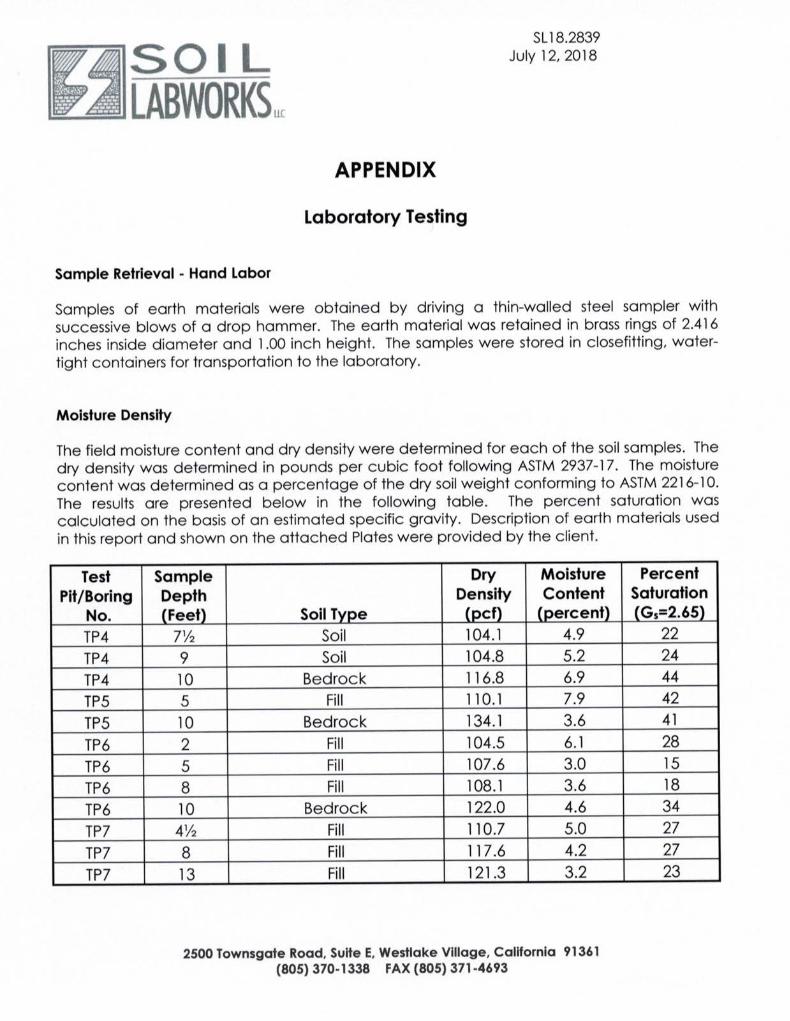
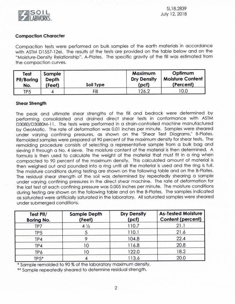
maximum depth of 26 feet. Samples of the earth materials were obtained and delivered
to the soils engineering laboratory of Soil Labworks, LLC for testing and analysis. Downhole
observation of the earth materials was performed by the engineering geologist.
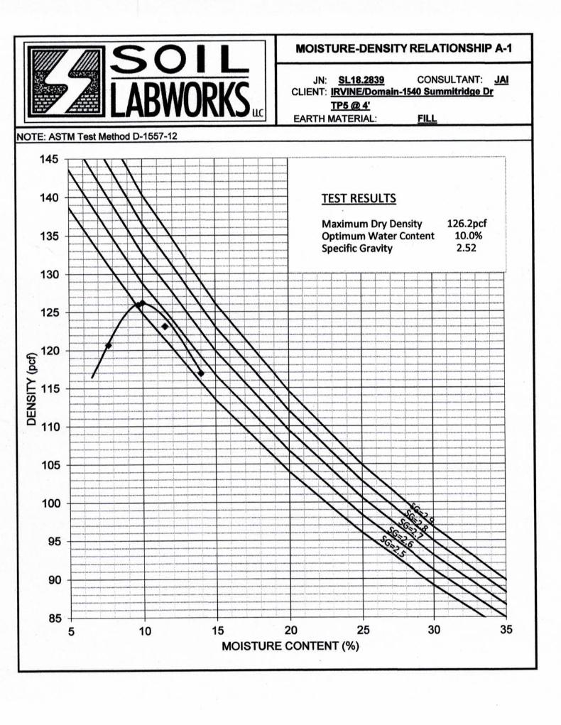
Office tasks included laboratory testing of selected soil samples, researching records on
file at the City of Los Angeles, reviewing historical topographic maps and aerial photographs,
preparing the Geologic Map and cross sections and performing engineering analysis. Earth
145 N. Sierra Madre Blvd., Suite #1 • Pasadena • California • 91107 • Phone: 626-844-6641/Fax: 626-604-0394
October 3, 2018IC 17188-IPage 3
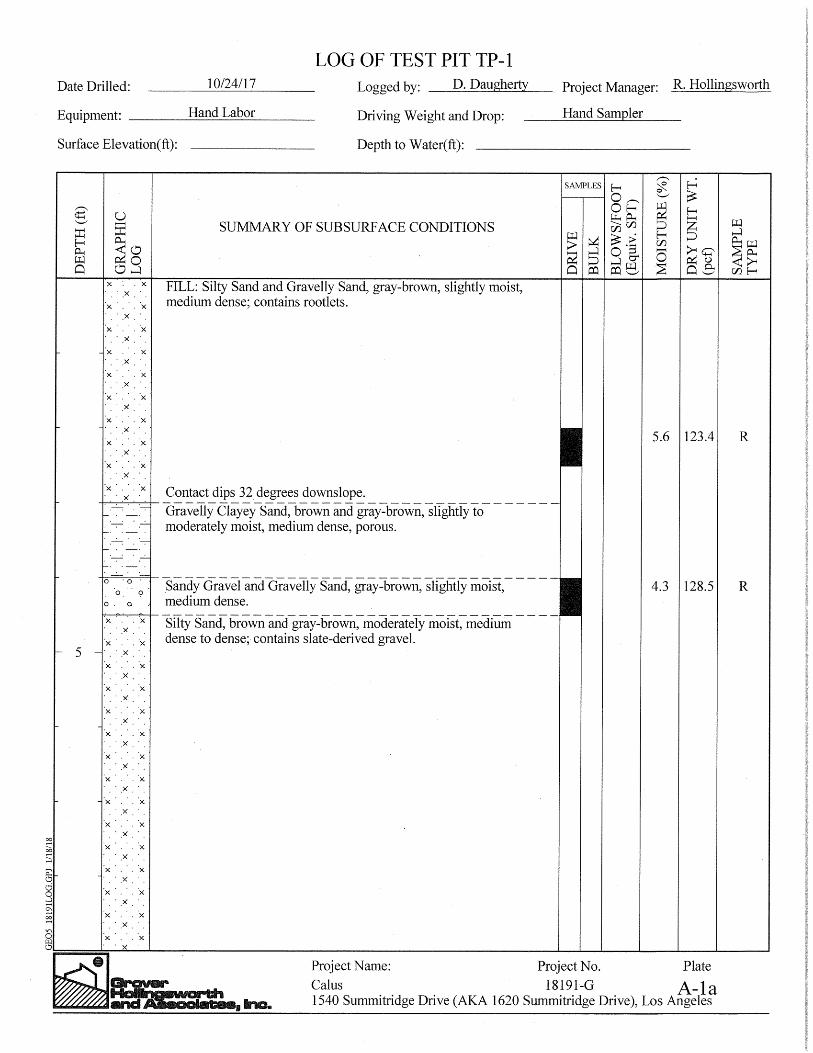
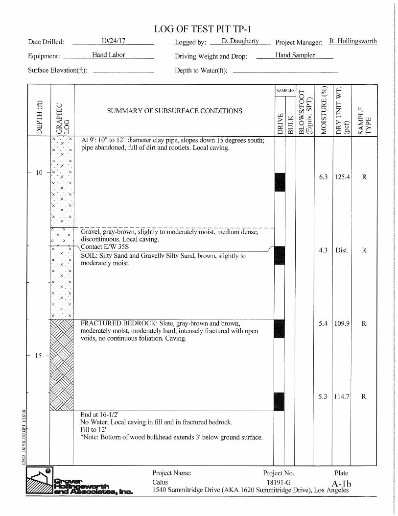
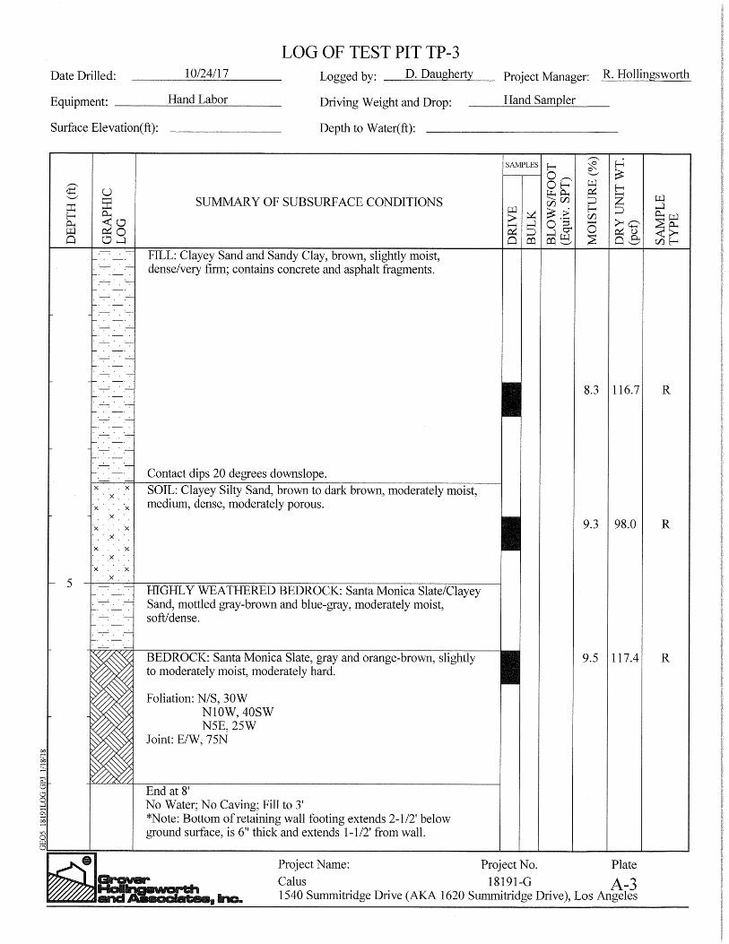
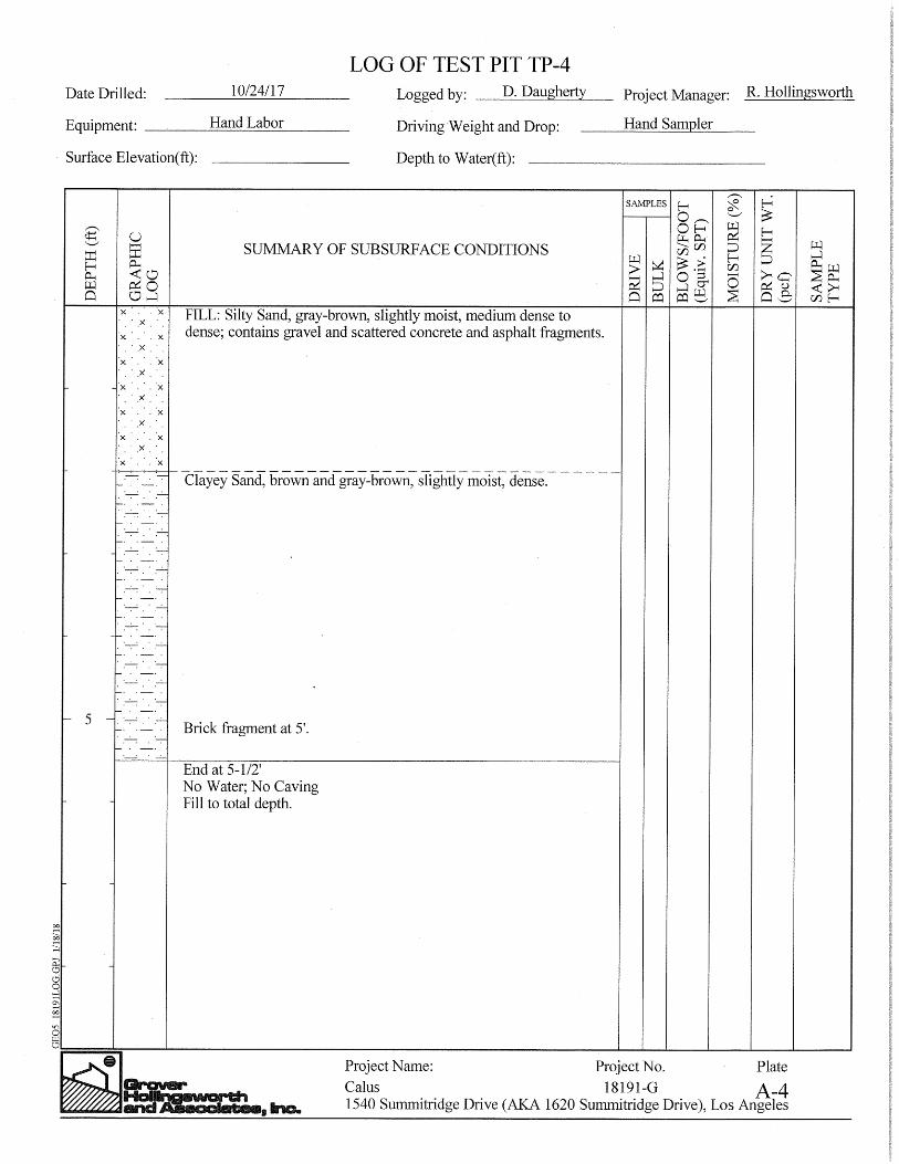
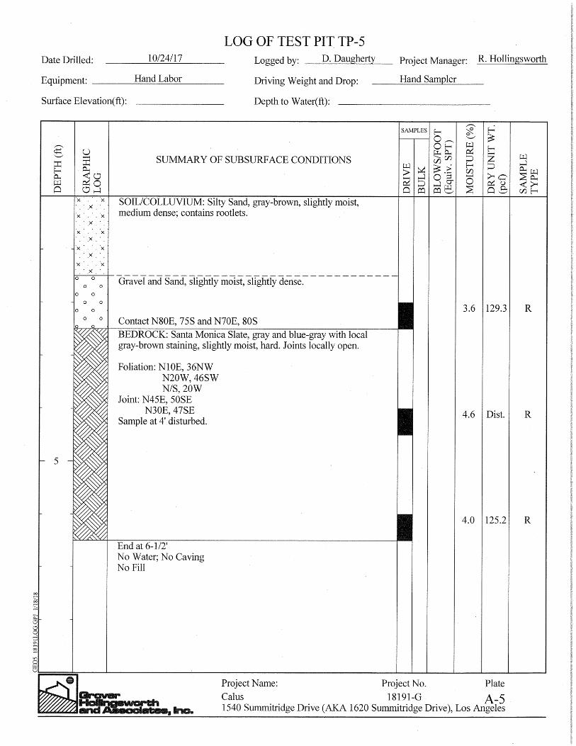
materials exposed in the test pits are described on the enclosed Log of Test Pits. Appendix
I contains a discussion of the laboratory testing procedures and results.
The proposed project, surface geologic conditions, and the location of the test pits are
shown on the Geologic Map. Subsurface distribution of the earth materials, projected
geologic structure, and the proposed project are shown on Sections A through E. Sections
B, D, and E form the basis for the enclosed stability calculations.
RESEARCH - PREVIOUS WORK
The building and grading records of the City of Los Angeles Department of Building and
Safety were researched prior to preparing this report. The records did not contain geologic
or geotechnical reports for the site.
Grover Hollingsworth and Associates, Inc. (GHA) explored the site in October of 2017 for a
prospective buyer of the property. It is our understanding that their work was cancelled due
to the thickness of undocumented fill and the seller’s reluctance to extend the due-diligence
period. GHA presented their logs of test pits in their report, “Geologic Information, Lot 3,
Arb 1, Tract 7996, 1540 Summitridge Drive (aka 1620 Summitridge Drive) Los Angeles,
California,” dated January 17, 2018.
Irvine Geotechnical and Jon A. Irvine has reviewed the subsurface exploration and
engineering geologic interpretation contained in the referenced reports. Irvine Geotechnical
and the undersigned engineering geologist generally concurs with the reported findings and
accepts professional responsibility for utilizing the data. Logs of test pits are appended to
the report. The location of the test pits are shown on the enclosed Geologic Map.
145 N. Sierra Madre Blvd., Suite #1 • Pasadena • California • 91107 • Phone: 626-844-6641/Fax: 626-604-0394
October 3, 2018IC 17188-IPage 4
PROPOSED PROJECT
Information concerning the proposed project was provided by the client. The preliminary
plans prepared by Domaen were a guide for preparing this report. It is proposed to develop
the site with a new residence and swimming pool. The structure will be two-story and have
a two partial basements. The main floor and lower basement levels will open onto the lower
slope and decks. A pool is planned on the main level as part of a structural deck.
Retaining walls up to 30 feet high are planned to support grade changes. Grading will be
limited to improving site conditions, trimming slopes, exporting soils from the basement
excavations, and backfilling retaining walls.
Formal plans have not been prepared and await the conclusions and recommendations of
this report.
SITE DESCRIPTION
The subject property consists of a graded and vacant hillside lot, on the south flank of the
Santa Monica Mountains, in the Beverly Hills Post Office section of the City of Los Angeles,
California. It is located on Summitridge Drive, south of the intersection with Ferrari Drive,
east of San Ysidro Drive, and approximately one mile north of Sunset Boulevard. The upper
(northern) and lower (southern) property lines are bounded by Summitridge Drive. The site
is vacant. The surrounding area is developed with single-family residences.
Geomorphically, the property is located at the head of a south-draining secondary canyon,
which is flanked by south-trending ridges. Past grading has consisted of placing fill into the
canyon. A bulkhead-type retaining wall is present along the northern property line along the
downhill side of the street. Another cast-in-place concrete wall is present along the
southern property line along the uphill side of Summitridge Drive.
145 N. Sierra Madre Blvd., Suite #1 • Pasadena • California • 91107 • Phone: 626-844-6641/Fax: 626-604-0394
October 3, 2018IC 17188-IPage 5
Vegetation on the site consists of mature trees and a thick assemblage of plants, grasses
and weeds. Surface drainage generally is by sheet flow runoff down the contours of the
land toward the south-southeast.
GROUNDWATER
Groundwater was not encountered during exploration. Seasonal fluctuations in groundwater
levels may occur due to variations in climate, irrigation, and other factors not evident at the
time of the exploration. Fluctuations in groundwater levels may also occur across the site.
EARTH MATERIALS
Fill
Fill, associated with previous site grading, underlies portions of the site to a maximum
observed thickness of 18 feet in Test Pit 1 to more than 15 feet in the vicinity of Test Pit
6. The fill consists of gravelly sand that is brown, slightly moist, and medium dense. The
fill contains concrete fragments and asphalt debris up to 12 inches in length that appear
to have been cast over the slope from the top.
Soil
Natural residual soils were encountered in Test Pits 3 and 4. The soil consists of gravelly
sand that is brown, very slightly moist, medium dense and contains gravel-sized slate rock
fragments.
145 N. Sierra Madre Blvd., Suite #1 • Pasadena • California • 91107 • Phone: 626-844-6641/Fax: 626-604-0394

October 3, 2018IC 17188-IPage 6
Bedrock
Bedrock underlying the site and encountered in the test pits consists of slate of the Santa
Monica Formation as mapped by T.W. Dibblee, (Geologic Map of the Santa Monica
Mountains and Vicinity, CD Compilation, 2001). The bedrock is well exposed in road cuts
adjacent to the site offsite toward the southeast and southwest. The bedrock is gray to
blue-gray, moderately hard to hard, moderately to slightly weathered, and fractured to
massive.
GEOLOGIC STRUCTURE
The bedrock described is common to this area of the Santa Monica Mountains and the
geologic structure is consistent with regional trends. Foliation planes mapped generally
strike northeast to northwest and dip moderately toward the northwest and southwest. Joint
planes mapped are randomly oriented and steeply dipping.
The geologic structure of the bedrock is favorably oriented for stability of the site and
proposed project. Recommendations to eliminate or support any unfavorably oriented
foliation are presented in the CONCLUSIONS AND RECOMMENDATIONS section of this
report.
GENERAL SEISMIC CONSIDERATIONS
Southern California is located in an active seismic region and numerous known and
undiscovered earthquake faults are present in the region. Hazards associated with fault
rupture and earthquakes include direct affects such as strong ground shaking and ground
rupture, as well as secondary effects such as liquefaction, landsliding and lurching. The
United States Geological Survey (USGS), California Geologic Survey (CGS), Southern
California Earthquake Center (SCEC), private consultants and universities have been
145 N. Sierra Madre Blvd., Suite #1 • Pasadena • California • 91107 • Phone: 626-844-6641/Fax: 626-604-0394

October 3, 2018IC 17188-IPage 7
studying earthquakes in southern California for several decades. Early studies were
directed toward earthquake prediction and early warning of strong ground shaking.
Research and practice have shown that earthquake prediction is not practical or sufficiently
accurate to benefit the general public. Also, several recent and damaging earthquakes have
occurred on faults that were unknown prior to rupture. Current standards and the California
Building Code call for earthquake resistant design of structures as opposed to prediction.
Alquist-Priolo Fault Rupture Hazard Study Zone
California faults are classified as active, potentially active or inactive. Faults from past
geologic periods of mountain building, but do not display any evidence of recent offset are
considered “inactive” or “potentially active.” Faults that have historically produced
earthquakes or show evidence of movement within the Holocene (past 11,000 years) are
considered “active faults.” Active faults that are capable of causing large earthquakes may
also cause ground rupture. The Alquist-Priolo Act of 1972 was enacted to protect structures
from hazards associated with fault ground rupture. No known active faults cross the subject
property and the site is not located within an Alquist-Priolo Fault Rupture Hazard Study Zone.
The ground rupture hazard at the site is considered nil.
Building Code Seismic Coefficients
Seismic design parameters within the Building Code include amplification of the seismic
forces on the structure depending on the soil type, distance to seismic source and intensity
of shaking. The purpose of the code seismic design parameters is to prevent collapse of
structures and loss of life during strong ground shaking. Cosmetic damage should be
expected.
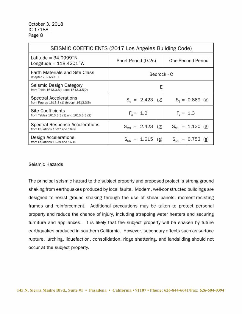
The following table lists the applicable seismic coefficients for the 2017 Los Angeles
Building Code.
145 N. Sierra Madre Blvd., Suite #1 • Pasadena • California • 91107 • Phone: 626-844-6641/Fax: 626-604-0394
October 3, 2018IC 17188-IPage 8
SEISMIC COEFFICIENTS (2017 Los Angeles Building Code)
Latitude = 34.0999ENLongitude = 118.4201EW
Short Period (0.2s) One-Second Period
Earth Materials and Site ClassChapter 20 - ASCE 7
Bedrock - C
Seismic Design Categoryfrom Table 1613.3.5(1) and 1613.3.5(2)
E
Spectral Accelerations from Figures 1613.3 (1) through 1613.3(6)
Ss = 2.423 (g) S1 = 0.869 (g)
Site Coefficientsfrom Tables 1613.3.3 (1) and 1613.3.3 (2) FA = 1.0 FV = 1.3
Spectral Response Accelerationsfrom Equations 16-37 and 16-38
SMS = 2.423 (g) SM1 = 1.130 (g)
Design Accelerations from Equations 16-39 and 16-40
SDS = 1.615 (g) SD1 = 0.753 (g)
Seismic Hazards
The principal seismic hazard to the subject property and proposed project is strong ground
shaking from earthquakes produced by local faults. Modern, well-constructed buildings are
designed to resist ground shaking through the use of shear panels, moment-resisting
frames and reinforcement. Additional precautions may be taken to protect personal
property and reduce the chance of injury, including strapping water heaters and securing
furniture and appliances. It is likely that the subject property will be shaken by future
earthquakes produced in southern California. However, secondary effects such as surface
rupture, lurching, liquefaction, consolidation, ridge shattering, and landsliding should not
occur at the subject property.
145 N. Sierra Madre Blvd., Suite #1 • Pasadena • California • 91107 • Phone: 626-844-6641/Fax: 626-604-0394
October 3, 2018IC 17188-IPage 9
Seismic Hazard Zones
The California State Legislature enacted the Seismic Hazards Mapping Act of 1990, which
was prompted by damaging earthquakes in California, and was intended to protect public
safety from the effects of strong ground shaking, liquefaction, landslides, and other
earthquake-related hazards. The Seismic Hazards Mapping Act requires that the State
Geologist delineate various “seismic hazards zones.” The maps depicting the zones are
released by the California Geological Survey.
The Seismic Hazards Mapping Act requires a site investigation by a certified engineering
geologist and/or civil engineer with expertise in geotechnical engineering, for projects sited
within a hazard zone. The investigation is to include recommendations for a “minimum level
of mitigation” that should reduce the risk of ground failure during an earthquake to a level
that does not cause the collapse of buildings for human occupancy. The Seismic Hazards
Mapping Act does not require mitigation to a level of no ground failure and/or no structural
damage.
Seismic Hazard Zone delineations are based on correlation of a combination of factors,
including: surface distribution of soil deposits; physical relief; depth to historic high
groundwater; shear strength of the soils; and occurrence of past seismic deformation. The
subject property is located within the United States Geologic Survey, Beverly Hills
Quadrangle. Seismic hazards within the Beverly Hills Quadrangle were evaluated by the CGS
in their report, “Seismic Hazard Zone Report for the Beverly Hills 7.5-minute Quadrangle,
Los Angeles County, California, Seismic Hazard Zone Report 023.” According to the
Seismic Hazard Zones Map, the subject property is within an area that has been subject to,
or may be subject to earthquake induced ground deformation.
145 N. Sierra Madre Blvd., Suite #1 • Pasadena • California • 91107 • Phone: 626-844-6641/Fax: 626-604-0394
October 3, 2018IC 17188-IPage 10
Ground Motion
Spectral accelerations and peak ground accelerations at the site were determined for the
Risk-Targeted Maximum Considered Earthquake (MCER) and Geometric Mean Peak Ground
Acceleration (MCEG) following the procedures in ASCE 7-10 and the 2017 Building Code.
The computed PGAM for this site is 0.936g. According to the USGS deaggregation website
(https://earthquake.usgs.gov/hazards/interactive/), and using a ground motion with a 10
percent probability of exceedance in 50 years, the modal de-aggregated earthquake PGA
and moment magnitude are 0.465g and 6.34, respectively. The modal distance to the
ground motion source is 8.42 km. For a ground motion with a 2 percent probability of
exceedance in 50 years, the modal de-aggregated earthquake PGA and moment magnitude
are 0.924g and 6.9, respectively. The modal distance to the ground motion source is 4.36
km.
SLOPE STABILITY
Gross Stability
Slopes affecting the subject property include a 60-foot high slope between the upper and
lower sections of Summitridge Drive. The slope is blanketed by a variable thickness of fill
over a thin soil layer and bedrock. Within the planned development footprint, most of the
fill and soil will be removed to expose bedrock. Fill and soil on the uphill side of the
structure will be supported by retaining walls. Along the downhill side of the residence, it
is recommended that the fill be trimmed to 2:1 and then step up to grade via retaining walls
for the residence. The 2:1 trims would then transition to meet the offsite grades in the
narrow side yards.
The retaining walls along the downhill side of the residence should be designed as soldier
piles to retain the fill and soil to the bedrock contact with an equivalent fluid pressure of 45
145 N. Sierra Madre Blvd., Suite #1 • Pasadena • California • 91107 • Phone: 626-844-6641/Fax: 626-604-0394
October 3, 2018IC 17188-IPage 11
pcf. The recommended seismic surcharge on these soldier piles is 15 pcf (total 60 pcf for
static plus seismic). Soldier piles are recommended to stabilize the existing toe-of-slope
retaining wall with an equivalent fluid pressure of 60 pcf from the top of the wall to a depth
of 10 feet. The recommended seismic surcharge on these soldier piles is 20 pcf (total 80
pcf for static plus seismic). Soldier piles are also recommended along either side of the
development envelop to stabilize existing fill and soil slopes. There is no seismic surcharge
on soldier piles outside of the building envelope.
Typical locations of soldier piles are shown on the Geologic Map and geotechnical sections
A through E. Sections B, D, and E are believed to be the most critical slopes with respect
to stability.
The gross stability of the slopes shown in Sections B, D, and E was calculated using a
computerized version of Spencer’s method (SLIDE Version 8.017 developed by
ROCSCIENCE, Inc.). Both circular and wedge-type failures were analyzed.
The seismic stability of the site was calculated in conformance with Southern California
Earthquake Center (SCEC), 2002, "Recommended Procedures for Implementation of DMG
Special Publication 117 and California Geological Survey (CGS), Special Publication 117A,
2008 "Guidelines for Evaluating and Mitigating Seismic Hazards in California." Using the
screening procedure and for a maximum allowable displacement of 5 cm, the horizontal
acceleration (Keq) is 0.274g. For a maximum allowable displacement of 15 cm, the
horizontal acceleration (Keq) is 0.202g.
The analysis shows that the subject property and proposed slopes will be grossly stable with
a factor of safety in excess of 1.5 under static conditions and in excess of 1.0 under
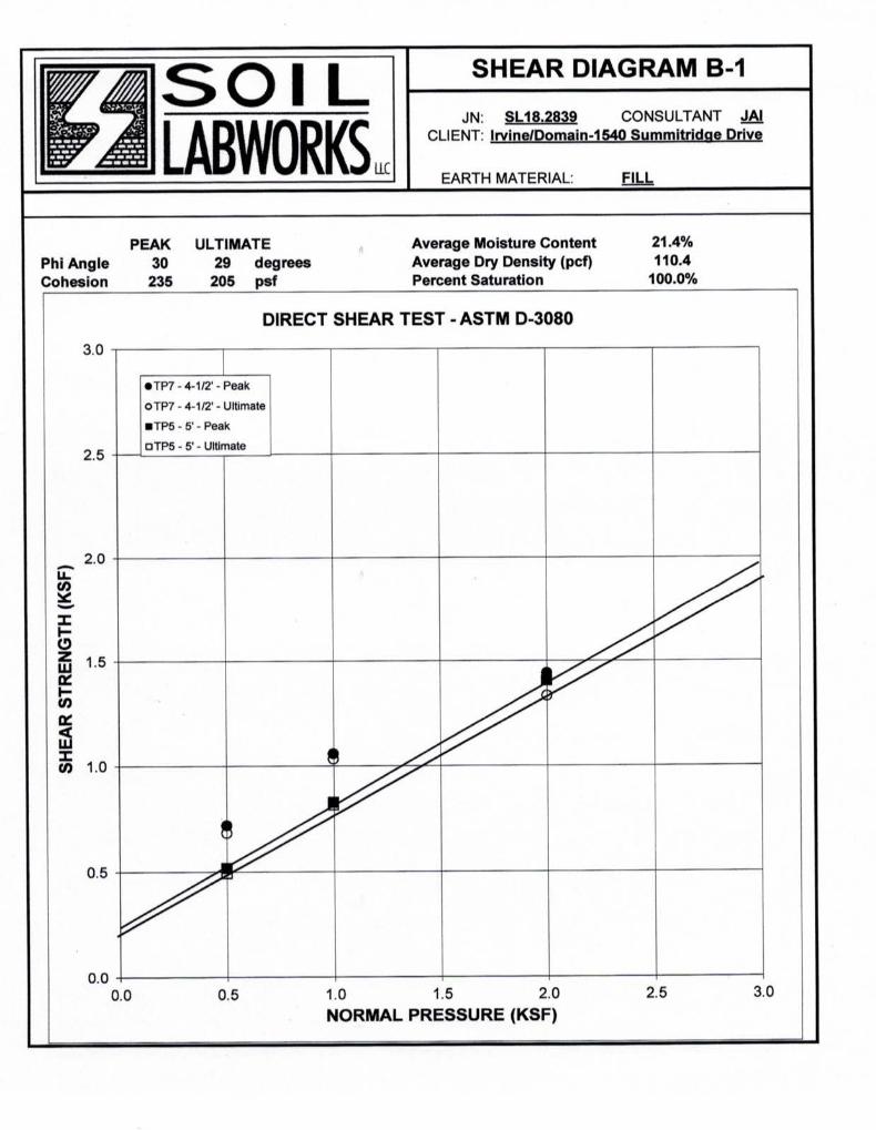
seismic conditions. The calculations use the shear tests of samples believed to represent
the earth materials encountered during exploration. The cross sections and geologic
structure used are the most critical for the slopes analyzed.
145 N. Sierra Madre Blvd., Suite #1 • Pasadena • California • 91107 • Phone: 626-844-6641/Fax: 626-604-0394
October 3, 2018IC 17188-IPage 12
Surficial Stability
Most of the fill slopes will be removed and/or supported by the proposed development,
Below the residence, it is recommended that the fill be trimmed to 2:1 as shown on
Sections B and C. Based upon the enclosed calculations, it is reasonable to assume that
the existing fill slopes remaining outside residence footprint will be surficially stable.
The method of analysis used is the "parallel seepage model." The assumptions of this
method are: a uniform planar slope; uniform soil density and shear strength; and uniform
seepage parallel to the slope. The validity of the analysis depends, in part, by how closely
the assumptions model the field conditions.
For surficial deposits overlying natural slopes, it is the opinion of Irvine Geotechnical that
the assumptions of the "parallel seepage model" are not completely satisfied. Thus,
though the calculation shows that the surficial materials on the site are stable with a factor
of safety in excess of 1.5, the mitigating measures recommended in the CONCLUSIONS
AND RECOMMENDATIONS of this report should be implemented during development of the
site.
CONCLUSIONS AND RECOMMENDATIONS
General Findings
The conclusions and recommendations of this exploration are based upon seven test pits,
field geologic mapping, research of available records, consultation, years of experience
observing similar properties in similar settings and review of the development plans. It is
the finding of Irvine Geotechnical that construction of the proposed project is feasible from
a geologic and soils engineering standpoint provided the advice and recommendations
145 N. Sierra Madre Blvd., Suite #1 • Pasadena • California • 91107 • Phone: 626-844-6641/Fax: 626-604-0394
October 3, 2018IC 17188-IPage 13
contained in this report are included in the plans and are implemented during construction.
The recommended bearing material is the bedrock. The site is blanketed by a variable
thickness of fill and soil over slate bedrock. The existing fill and soil are not recommended
for foundation or slab support. Portions of the basement will penetrate the fill and soil to
expose bedrock. Deepened foundations are recommended to support portions of the
proposed structures located over thick fill and soil and/or adjacent to slopes. Conventional
foundations may be used to support portions of the proposed structures that are sufficiently
tucked into the slope expose bedrock.
Geotechnical Issues
Geotechnical issues affecting the site include: existing fill slopes steeper than 2:1;
inadequate safety factor of existing slopes; an undocumented retaining wall along the
southern property that is to remain; and high temporary excavations adjacent to property
lines and the public right-of-way required to construct the basement retaining walls.
Existing slopes below the proposed residence should be trimmed to 2:1 as shown on
Sections B and C. The 2:1 trims should transition to meet the existing slope gradients near
the western and eastern property lines. Soldier piles are recommended to increase stability
of fill slopes steeper than 2:1 that cannot be trimmed.
Soldier piles are recommended to increase the stability of the site to at least 1.5 (static)
and 1.0 (seismic).
The existing retaining wall along the southern property line should be supported by soldier
piles to ensure stability in conformance with the current code.
Shoring will be required to support temporary excavations and property lines.
145 N. Sierra Madre Blvd., Suite #1 • Pasadena • California • 91107 • Phone: 626-844-6641/Fax: 626-604-0394
October 3, 2018IC 17188-IPage 14
SITE PREPARATION
Surficial materials consisting of fill and soil are present on the site. Where feasible,
remedial grading is recommended to improve site conditions for support of slabs.
Otherwise, slabs should be structurally designed to span the fill between deepened
foundation elements.
General Grading Specifications
The following guidelines may be used in preparation of the grading plan and job
specifications. Irvine Geotechnical would appreciate the opportunity of reviewing the plans
to insure that these recommendations are included. The grading contractor should be
provided with a copy of this report.
A. The site should be prepared to receive compacted fill by removing allvegetation, debris, existing fill, and soil. The exposed excavated area shouldbe observed by the soils engineer or geologist prior to placing compacted fill. The exposed grade should be scarified to a depth of six inches, moistened tooptimum moisture content, and recompacted to 90 percent of the maximumdensity.
B. Fill, consisting of soil approved by the soils engineer, shall be placed inhorizontal lifts and compacted in six inch layers with suitable compactionequipment. The excavated onsite materials are considered satisfactory forreuse in the controlled fills. Any imported fill shall be observed by the soilsengineer prior to use in fill areas. Rocks larger than six inches in diametershall not be used in the fill.
C. The fill shall be compacted to at least 90 percent of the maximum laboratorydensity for the material used. Where cohesionless soil (less than 15 percentfiner than 0.005 millimeters) is used for fill, it shall be compacted to aminimum of 95 percent relative compaction. The fill should be placed at amoisture content that is at or within 3 percent over optimum. The maximumdensity and optimum moisture content shall be determined by ASTM D 1557-12 or equivalent.
145 N. Sierra Madre Blvd., Suite #1 • Pasadena • California • 91107 • Phone: 626-844-6641/Fax: 626-604-0394

October 3, 2018IC 17188-IPage 15
D. Field observation and testing shall be performed by the soils engineer duringgrading to assist the contractor in obtaining the required degree of compactionand the proper moisture content. Where compaction is less than required,additional compactive effort shall be made with adjustment of the moisturecontent, as necessary, until 90 percent compaction is obtained. Onecompaction test is required for each 500 cubic yards or two vertical feet of fillplaced.
Fill Slopes
Fill slopes may be constructed at a 2:1 gradient and should be supported laterally by
retaining walls. The base of all fills and the axis of drainage courses require subdrains.
Cut/Trim Slopes
Cut/trim slopes may be created at a 2:1 gradient.
Excavation Characteristics
The test pits did encounter hard, cemented bedrock. Excavation difficulty is a function of
the degree of weathering and amount of fracturing within the bedrock. The bedrock generally
becomes harder and more difficult to excavate with increasing depth. Hard cemented layers
are also known to occur at random locations and depths and may be encountered during
foundation excavation. Should a hard cemented layer be encountered, coring or the use of
jackhammers may be necessary.
Caving layers may also be present in the fill. Casing, drilling muds, and/or special drilling
techniques should be anticipated for large-diameter drilled shafts in fill. Lagging will be
required for shored excavations.
145 N. Sierra Madre Blvd., Suite #1 • Pasadena • California • 91107 • Phone: 626-844-6641/Fax: 626-604-0394
October 3, 2018IC 17188-IPage 16
SWIMMING POOL
The proposed swimming pool will be part of the residence superstructure. The pool should
derive support entirely from the bedrock. This will require the use of a deepened foundation
system.
FOUNDATION DESIGN
General Conditions
The following foundation recommendations are minimum requirements. The structural
engineer may require footings that are deeper, wider, or larger in diameter, depending on
the final loads.
Spread Footings
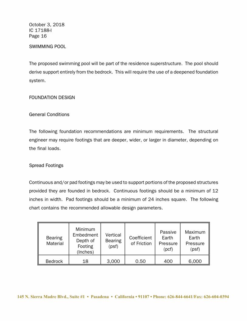
Continuous and/or pad footings may be used to support portions of the proposed structures
provided they are founded in bedrock. Continuous footings should be a minimum of 12
inches in width. Pad footings should be a minimum of 24 inches square. The following
chart contains the recommended allowable design parameters.
Bearing Material
MinimumEmbedment
Depth ofFooting(Inches)
VerticalBearing
(psf)
Coefficient of Friction
PassiveEarth
Pressure(pcf)
MaximumEarth
Pressure(psf)
Bedrock 18 3,000 0.50 400 6,000
145 N. Sierra Madre Blvd., Suite #1 • Pasadena • California • 91107 • Phone: 626-844-6641/Fax: 626-604-0394
October 3, 2018IC 17188-IPage 17
Increases in the bearing value are allowable at a rate of 600 pounds per square foot for
each additional foot of footing width or depth to a maximum of 6,000 pounds per square
foot. For bearing calculations, the weight of the concrete in the footing may be neglected.
The bearing value shown above is for the total of dead and frequently applied live loads and
may be increased by one third for short duration loading, which includes the effects of wind
or seismic forces.
The on-site soils are non-expansive. Footings should be reinforced following the
recommendations of the structural engineer. It is recommended that continuous footings
be reinforced with a minimum of four #4 steel bars; two placed near the top and two near
the bottom of the footings. Footings should be cleaned of all loose soil, moistened, free
of shrinkage cracks and approved by the geologist and geotechnical engineer prior to placing
forms, steel or concrete.
Footings should not be supported by retaining wall backfill or derive support within the active
wedge behind the retaining wall. Foundations adjacent to basements should be deepened
below a 1:1 plane projected up from the base of the retaining wall. Alternatively,
foundations adjacent to basements may be designed as a grade beam and structurally
connected to the wall.
Deepened Foundations - Friction Piles
Drilled, cast-in-place concrete friction piles are recommended to support portions of the
proposed structures located adjacent to slopes and/or thick fill and soil. Piles should be
a minimum of 24 inches in diameter and a minimum of 10 feet into bedrock. Piles may be
assumed fixed at 3 feet into bedrock. For the vertical forces, the piles may be designed for
a skin friction of 700 pounds per square foot for that portion of pile in contact with the
bedrock. The friction value is for the total of dead and frequently applied live loads and may
145 N. Sierra Madre Blvd., Suite #1 • Pasadena • California • 91107 • Phone: 626-844-6641/Fax: 626-604-0394
October 3, 2018IC 17188-IPage 18
be increased by one third for short duration loading, which includes the effects of wind or
seismic forces.
Soldier Piles
The retaining walls along the downhill side of the residence should be designed as soldier
piles to retain the fill and soil to the bedrock contact with an equivalent fluid pressure of 45
pcf. The recommended seismic surcharge on these soldier piles is 15 pcf (total 60 pcf for
static plus seismic). Soldier piles are recommended to stabilize the existing toe-of-slope
retaining wall with an equivalent fluid pressure of 60 pcf from the top of the wall to a depth
of 10 feet. The recommended seismic surcharge on these soldier piles is 20 pcf (total 80
pcf for static plus seismic). Soldier piles are also recommended along either side of the
development envelop to stabilize existing fill and soil slopes. There is no seismic surcharge
on retaining walls outside of the building envelope.
Typical locations of soldier piles are shown on the Geologic Map and geotechnical sections
A through E. Sections B, D, and E are believed to be the most critical slopes with respect
to stability.
Soldier piles should be a minimum of 24 inches in diameter and a minimum of 10 feet into
bedrock. Piles may be assumed fixed at 3 feet into bedrock. The piles may be designed
for a skin friction of 700 pounds per square foot for that portion of pile in contact with the
bedrock. Soldier piles should be spaced a maximum of 10 feet on center.
Lateral Design - Isolated Piles and Loading Normal to Row of Piles
The existing fill and soil on the site are subject to downhill creep. Friction pile shafts are
subject to lateral loads due to the creep forces. Friction pile shafts should be designed for
a lateral load of 1,000 pounds per linear foot for each foot of shaft exposed to the existing
145 N. Sierra Madre Blvd., Suite #1 • Pasadena • California • 91107 • Phone: 626-844-6641/Fax: 626-604-0394
October 3, 2018IC 17188-IPage 19
fill and soil. Soldier piles should be designed for the specified soil pressures, but not an
additional creep force.
Resistance to lateral loading may be provided by passive earth pressure within the bedrock.
Passive earth pressure may be computed as an equivalent fluid having a density of 400
pounds per cubic foot. The maximum allowable earth pressure is 6,000 pounds per square
foot. For design of isolated piles and the direction of loading does not coincide with a row
of piles, the allowable passive and maximum earth pressures may be increased by 100
percent. Piles spaced more than 3 pile diameters on center may be considered isolated.
All piles should be designed to resist lateral forces in conformance with Section 1810.2 of
the Building Code. This may require tying the piles in two horizontal directions with grade
beams, structural slabs or a structural pool shell.
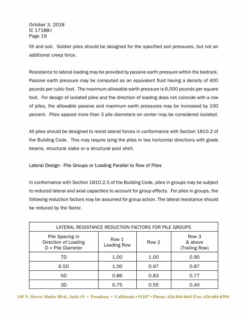
Lateral Design - Pile Groups or Loading Parallel to Row of Piles
In conformance with Section 1810.2.5 of the Building Code, piles in groups may be subject
to reduced lateral and axial capacities to account for group effects. For piles in groups, the
following reduction factors may be assumed for group action. The lateral resistance should
be reduced by the factor.
LATERAL RESISTANCE REDUCTION FACTORS FOR PILE GROUPS
Pile Spacing inDirection of LoadingD = Pile Diameter
Row 1Leading Row Row 2
Row 3& above
(Trailing Row)
7D 1.00 1.00 0.90
6.5D 1.00 0.97 0.87
5D 0.86 0.83 0.77
3D 0.75 0.55 0.40
145 N. Sierra Madre Blvd., Suite #1 • Pasadena • California • 91107 • Phone: 626-844-6641/Fax: 626-604-0394
October 3, 2018IC 17188-IPage 20
* Recommended by Caltrans GeoResearch Group
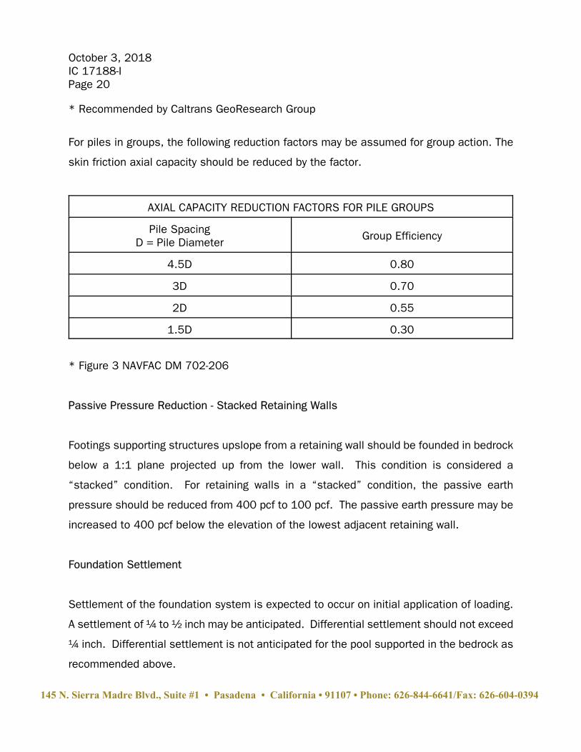
For piles in groups, the following reduction factors may be assumed for group action. The
skin friction axial capacity should be reduced by the factor.
AXIAL CAPACITY REDUCTION FACTORS FOR PILE GROUPS
Pile SpacingD = Pile Diameter
Group Efficiency
4.5D 0.80
3D 0.70
2D 0.55
1.5D 0.30
* Figure 3 NAVFAC DM 702-206
Passive Pressure Reduction - Stacked Retaining Walls
Footings supporting structures upslope from a retaining wall should be founded in bedrock
below a 1:1 plane projected up from the lower wall. This condition is considered a
“stacked” condition. For retaining walls in a “stacked” condition, the passive earth
pressure should be reduced from 400 pcf to 100 pcf. The passive earth pressure may be
increased to 400 pcf below the elevation of the lowest adjacent retaining wall.
Foundation Settlement
Settlement of the foundation system is expected to occur on initial application of loading.
A settlement of ¼ to ½ inch may be anticipated. Differential settlement should not exceed
¼ inch. Differential settlement is not anticipated for the pool supported in the bedrock as
recommended above.
145 N. Sierra Madre Blvd., Suite #1 • Pasadena • California • 91107 • Phone: 626-844-6641/Fax: 626-604-0394
October 3, 2018IC 17188-IPage 21
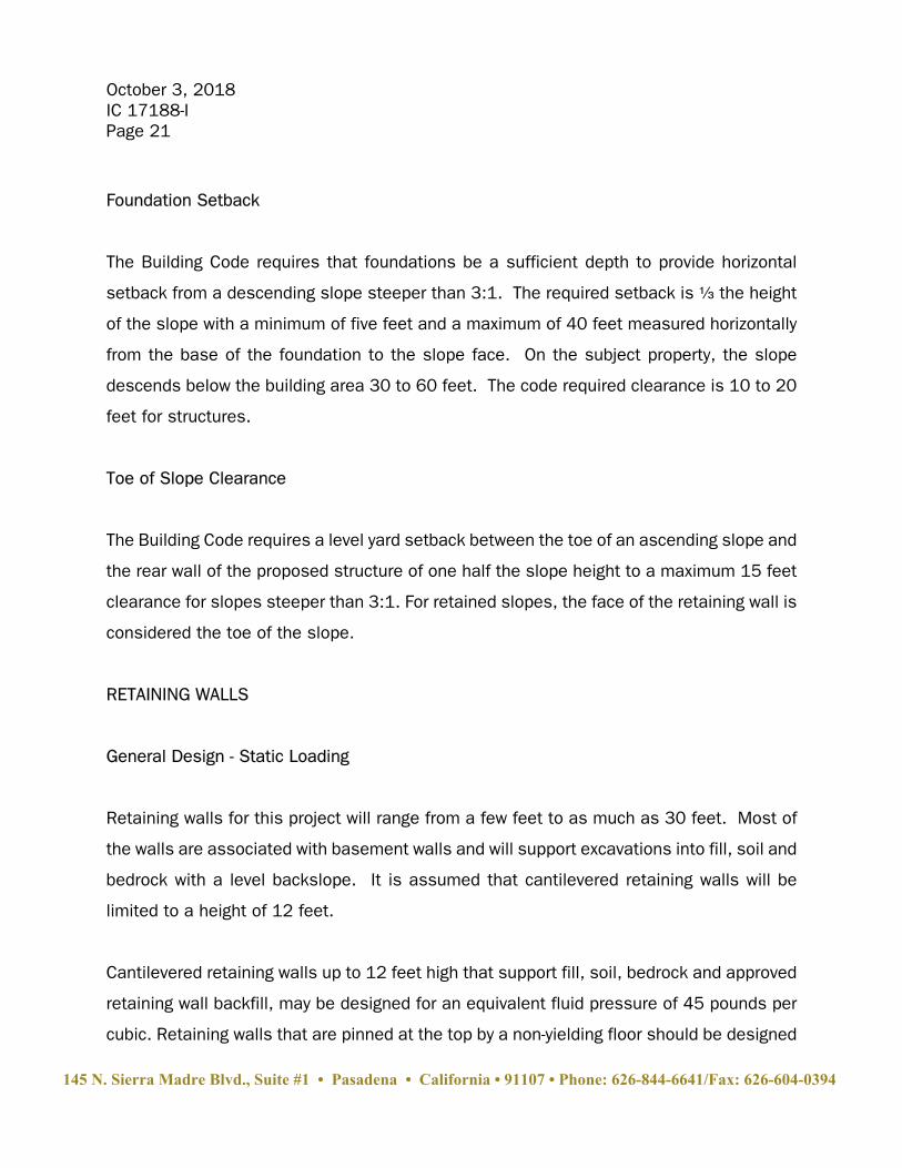
Foundation Setback
The Building Code requires that foundations be a sufficient depth to provide horizontal
setback from a descending slope steeper than 3:1. The required setback is a the height
of the slope with a minimum of five feet and a maximum of 40 feet measured horizontally
from the base of the foundation to the slope face. On the subject property, the slope
descends below the building area 30 to 60 feet. The code required clearance is 10 to 20
feet for structures.
Toe of Slope Clearance
The Building Code requires a level yard setback between the toe of an ascending slope and
the rear wall of the proposed structure of one half the slope height to a maximum 15 feet
clearance for slopes steeper than 3:1. For retained slopes, the face of the retaining wall is
considered the toe of the slope.
RETAINING WALLS
General Design - Static Loading
Retaining walls for this project will range from a few feet to as much as 30 feet. Most of
the walls are associated with basement walls and will support excavations into fill, soil and
bedrock with a level backslope. It is assumed that cantilevered retaining walls will be
limited to a height of 12 feet.
Cantilevered retaining walls up to 12 feet high that support fill, soil, bedrock and approved
retaining wall backfill, may be designed for an equivalent fluid pressure of 45 pounds per
cubic. Retaining walls that are pinned at the top by a non-yielding floor should be designed
145 N. Sierra Madre Blvd., Suite #1 • Pasadena • California • 91107 • Phone: 626-844-6641/Fax: 626-604-0394
October 3, 2018IC 17188-IPage 22
for an at-rest earth pressure. The recommended design at-rest earth pressure on restrained
basement walls is an equivalent fluid pressure of 65 pcf.
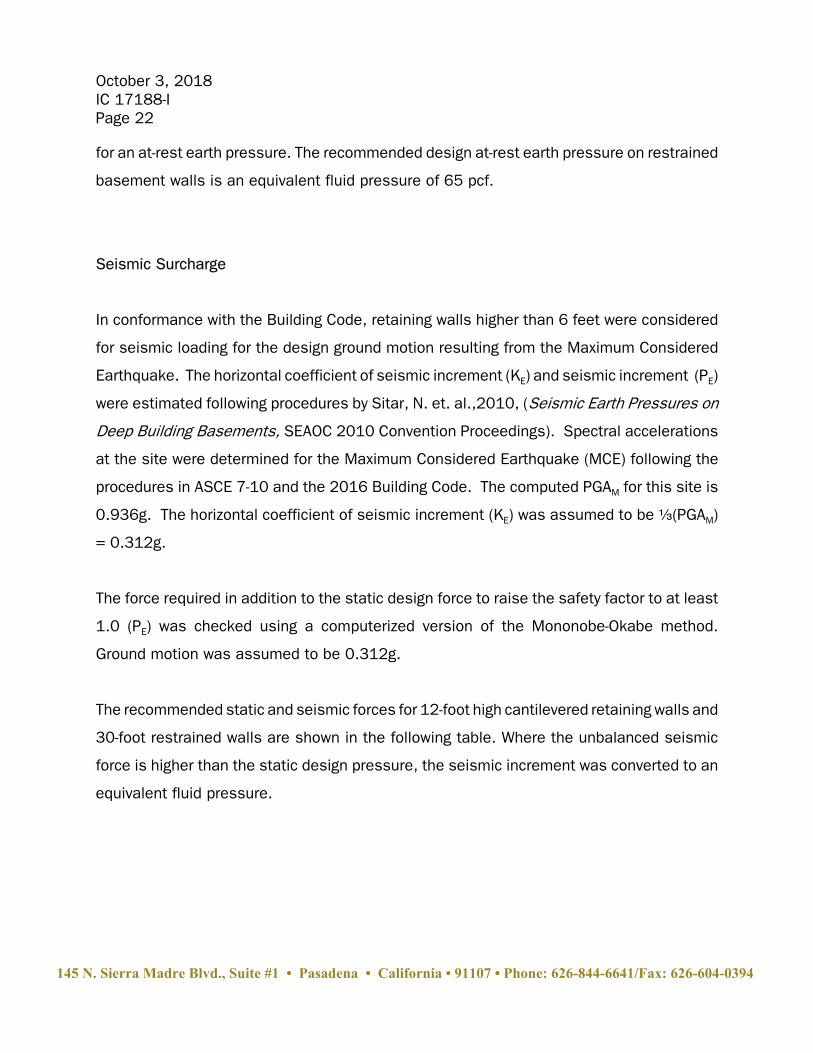
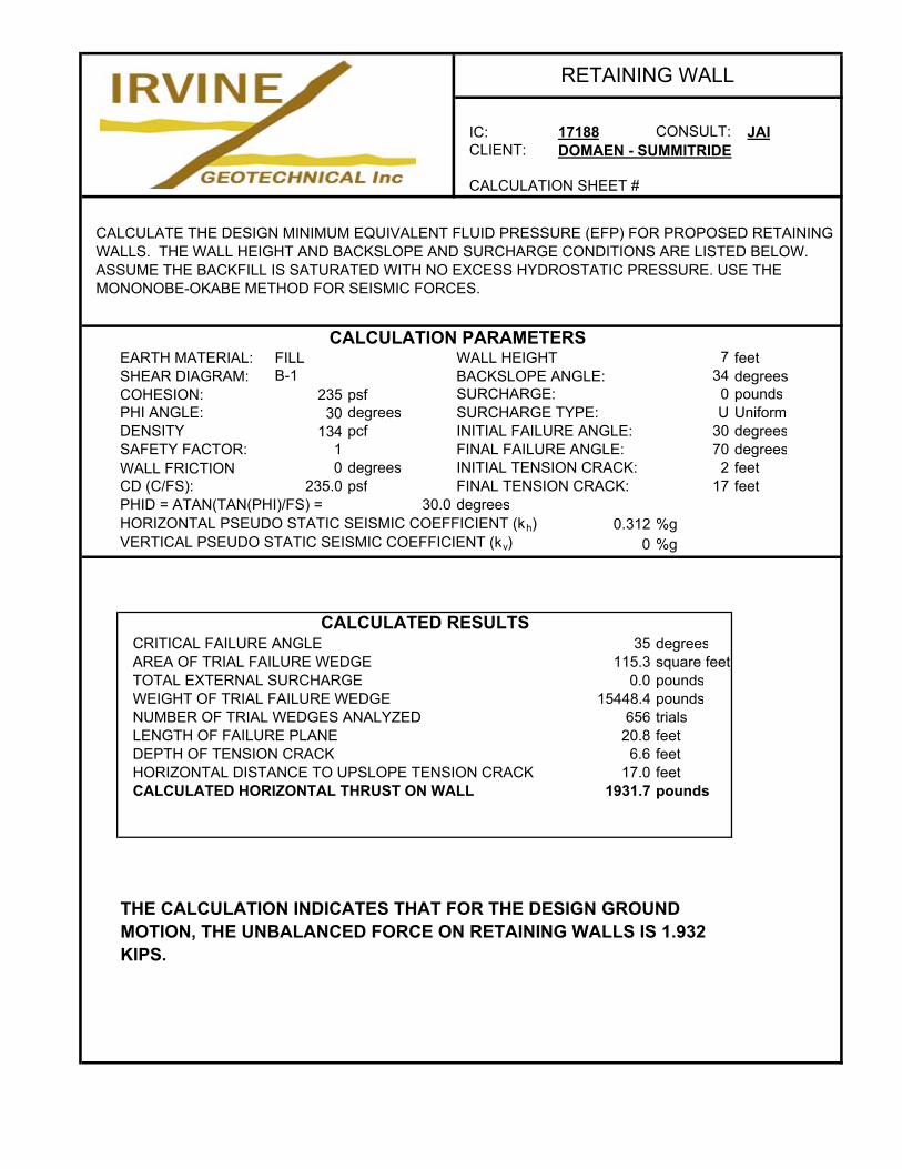
Seismic Surcharge
In conformance with the Building Code, retaining walls higher than 6 feet were considered
for seismic loading for the design ground motion resulting from the Maximum Considered
Earthquake. The horizontal coefficient of seismic increment (KE) and seismic increment (PE)
were estimated following procedures by Sitar, N. et. al.,2010, (Seismic Earth Pressures on
Deep Building Basements, SEAOC 2010 Convention Proceedings). Spectral accelerations
at the site were determined for the Maximum Considered Earthquake (MCE) following the
procedures in ASCE 7-10 and the 2016 Building Code. The computed PGAM for this site is
0.936g. The horizontal coefficient of seismic increment (KE) was assumed to be a(PGAM)
= 0.312g.
The force required in addition to the static design force to raise the safety factor to at least
1.0 (PE) was checked using a computerized version of the Mononobe-Okabe method.
Ground motion was assumed to be 0.312g.
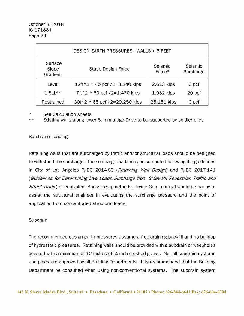
The recommended static and seismic forces for 12-foot high cantilevered retaining walls and
30-foot restrained walls are shown in the following table. Where the unbalanced seismic
force is higher than the static design pressure, the seismic increment was converted to an
equivalent fluid pressure.
145 N. Sierra Madre Blvd., Suite #1 • Pasadena • California • 91107 • Phone: 626-844-6641/Fax: 626-604-0394
October 3, 2018IC 17188-IPage 23
DESIGN EARTH PRESSURES - WALLS > 6 FEET
SurfaceSlope
Gradient Static Design Force Seismic
Force* Seismic
Surcharge
Level 12ft^2 * 45 pcf /2=3.240 kips 2.613 kips 0 pcf
1.5:1** 7ft^2 * 60 pcf /2=1.470 kips 1.932 kips 20 pcf
Restrained 30t^2 * 65 pcf /2=29.250 kips 25.161 kips 0 pcf
* See Calculation sheets** Existing walls along lower Summitridge Drive to be supported by soldier piles
Surcharge Loading
Retaining walls that are surcharged by traffic and/or structural loads should be designed
to withstand the surcharge. The surcharge loads may be computed following the guidelines
in City of Los Angeles P/BC 2014-83 (Retaining Wall Design) and P/BC 2017-141
(Guidelines for Determining Live Loads Surcharge from Sidewalk Pedestrian Traffic and
Street Traffic) or equivalent Boussinesq methods. Irvine Geotechnical would be happy to
assist the structural engineer in evaluating the surcharge pressure and the point of
application from concentrated structural loads.
Subdrain
The recommended design earth pressures assume a free-draining backfill and no buildup
of hydrostatic pressures. Retaining walls should be provided with a subdrain or weepholes
covered with a minimum of 12 inches of ¾ inch crushed gravel. Not all subdrain systems
and pipes are approved by all Building Departments. It is recommended that the Building
Department be consulted when using non-conventional systems. The subdrain system
145 N. Sierra Madre Blvd., Suite #1 • Pasadena • California • 91107 • Phone: 626-844-6641/Fax: 626-604-0394
October 3, 2018IC 17188-IPage 24
should discharge to the atmosphere or to an engineered sump via gravity. Surface drains
should not be connected to the subdrain system.
Backfill
Retaining wall backfill should be compacted to a minimum of 90 percent of the maximum
density as determined by ASTM D 1557-12. Where access between the retaining wall and
the temporary excavation prevents the use of compaction equipment, retaining walls should
be backfilled with ¾ inch crushed gravel to within 2 feet of the ground surface. Where the
area between the wall and the excavation exceeds 18 inches, the gravel must be vibrated
or wheel-rolled, and tested for compaction. The upper 2 feet of backfill above the gravel
should consist of a compacted fill blanket to the surface. Retaining wall backfill should be
capped with a paved surface drain or a concrete slab.
Foundation Design
Retaining wall footings may be sized per the FOUNDATION DESIGN section of this report.
Freeboard
Retaining walls surcharged by a sloping condition should be provided with a minimum of
24 inches of freeboard for slough protection. An open "V" drain should be placed behind
the wall so that all upslope flows are directed around the structure to the street.
TEMPORARY EXCAVATIONS
Temporary excavations will be required to construct the proposed retaining walls. The
excavations could be up to 30 feet in height and will expose fill and soil over bedrock.
Where not surcharged by existing footings or structures, the fill and soil are is capable of
145 N. Sierra Madre Blvd., Suite #1 • Pasadena • California • 91107 • Phone: 626-844-6641/Fax: 626-604-0394
October 3, 2018IC 17188-IPage 25
maintaining vertical excavations up to 5 feet. Where not surcharged by existing footings or
structures, the bedrock is capable of maintaining vertical excavations up to 7 feet per the
enclosed calculations. Where vertical excavations in the filll/soil and bedrock exceed 5 feet
and 7 feet in height, respectively, the upper portion should be trimmed to 1:1 (45 degrees).
West-facing temporary excavations into bedrock are not anticipated for this project. West-
facing excavations into bedrock, may unsupport foliation in the down-dip direction. West-
facing excavations into bedrock, if any, should be trimmed along lowest unsupported plane
(30 to 45 degrees).
It should be noted that regardless of stability, excavations that remove lateral support from
property lines or existing structures are not allowed by the Code. The following section from
Chapter 33 of the Building Code governs temporary excavations:
3307.3 Temporary excavations and shoring.
3307.3.1 General. Excavations shall not remove the lateral support from a public way, froman adjacent property or from an existing structure. For the purpose of this section, thelateral support shall be considered to have been removed when any of the followingconditions exist:
1. The excavation exposes any adverse geological formations, which would affectthe lateral support of a public way or an adjacent structure.
2. The excavation extends below a plane extending downward at an angle of 45degrees from the edge of the public way or an adjacent property.
Exception: Normal footing excavations not exceeding two feet in depth will notbe construed as removing lateral support.
3. The excavation extends below a plane extending downward at an angle of 45degrees from the bottom of an existing structure.
Vertical excavations removing lateral or vertical support from existing foundations or
property lines will require the use of temporary shoring.
145 N. Sierra Madre Blvd., Suite #1 • Pasadena • California • 91107 • Phone: 626-844-6641/Fax: 626-604-0394
October 3, 2018IC 17188-IPage 26
Shoring
Temporary shoring should be designed for an equivalent fluid pressure of 35 pounds per
cubic foot per the enclosed calculations. Shoring that is restrained by anchors or braces,
may be designed for a trapezoidal distribution of pressure. The recommended design earth
pressure on restrained shoring with a level backslope is 22H, where H is the retained height
in feet. Shoring that is integrated into the permanent retaining walls should be designed
for earth pressures conforming to the RETAINING WALL section of this report.
Shoring may consist of cast-in-place concrete piles with wood lagging. Shoring piles should
be a minimum of 12 inches in diameter and a minimum of 10 feet into bedrock below the
base of the excavation. Piles may be assumed fixed 3 feet into bedrock below the base of
the excavation. For the vertical forces, piles may be designed for a skin friction of 600
pounds per square foot for that portion of pile in contact with the bedrock. Soldier piles
should be spaced a maximum of 10 feet on center.
The friction value is for the total of dead and frequently applied live loads and may be
increased by one third for short duration loading, which includes the effects of wind or
seismic forces. Resistance to lateral loading may be provided by passive earth pressure
within the bedrock below the base of the excavation.
Passive earth pressure may be computed as an equivalent fluid having a density of 400
pounds per cubic foot. The maximum allowable earth pressure is 6,000 pounds per square
foot. For design of isolated piles, the allowable passive and maximum earth pressures may
be increased by 100 percent. Piles spaced more than 3 pile diameters on center may be
considered isolated.
145 N. Sierra Madre Blvd., Suite #1 • Pasadena • California • 91107 • Phone: 626-844-6641/Fax: 626-604-0394

October 3, 2018IC 17188-IPage 27
Lagging
Due to the sandy nature of the fill and soil, lagging will be required between piles. Due to
arching in the soils, pressure on the lagging will be less that on the shoring piles. It is
recommended that the lagging be designed for the full design pressure but be limited to a
maximum of 400 pounds per square foot. The void between the lagging and the back-cut
should be slurry-filled and observed by a representative of the geotechnical engineer.
Earth Anchors
Earth anchors (tie backs) may be employed to assist the shoring system. Pressure
grounted anchors are recommended. The active wedge angle behind shoring is assumed
to be a 30-degree plane (measured from the vertical) or the soil/bedrock contact, whichever
is deeper. The bonded length of earth anchors should extend at least 15 feet beyond the
active wedge. For preliminary design, an ultimate bond friction between the anchors and
the soil beyond the active wedge of 4,500 psf may be assumed for post-grouted anchors.
Testing of a percentage of the initial and representative anchors to 200 percent of the
design is recommended to verify the assumptions. The remaining anchors should be tested
to at least 150 percent of the design load. The installation and testing should conform to
the recommendations of the shoring engineer and City of Los Angeles Guidelines. The
testing should also be observed by a representative of the geotechnical engineer. Failure
or excessive movement of anchors may require longer bond length, additional post-grouting
or additional anchors.
145 N. Sierra Madre Blvd., Suite #1 • Pasadena • California • 91107 • Phone: 626-844-6641/Fax: 626-604-0394
October 3, 2018IC 17188-IPage 28
Dead Men
A bearing value of 5,000 psf may be assumed for dead men footings. A coefficient of
sliding friction of 0.50 may be assumed along the base of the footing. Passive pressure
may be assumed to be 400 pcf.
Deflection Monitoring
Prior to construction and excavation for the project, it is recommended that the existing
conditions along the property lines be documented and surveyed. Documentation should
include photographs and descriptions of the offsite structures and conditions. Survey
monuments should be affixed to representative structures and to points along the property
line and offsite. The survey points should be measured prior to construction to form a
baseline for determining settlement and/or deformation. Upon installation of the shoring
system, survey monuments should be affixed to the tops of representative piles so that
deflection can be measured.
Some deflection is expected for a well designed and constructed cantilevered shoring
system. Where offsite structures and the public right-of-way are located more than 30 feet
of the shored excavation, it is recommended that deflection be limited to 1 inch. Where
offsite structures and the public right-of-way are located within 30 feet of the shored
excavation, it is recommended that the deflection be limited to ½ inch or less.
The shored excavations and offsite structures should be visually inspected everyday. Survey
monuments should be measured once a month during the construction process. Should
the surveys reveal offsite deformation or excessive deflection of the shoring system, the
shoring engineer and geotechnical engineer should be notified. Excessive deflection may
require additional anchors and/or internal bracing to restrain the shoring system.
145 N. Sierra Madre Blvd., Suite #1 • Pasadena • California • 91107 • Phone: 626-844-6641/Fax: 626-604-0394
October 3, 2018IC 17188-IPage 29
Surcharge Loading
Shoring that is surcharged by traffic and/or structural loads should be designed to
withstand the surcharge. The surcharge loads may be computed following the guidelines
in City of Los Angeles P/BC 2017-141 (Guidelines for Determining Live Loads Surcharge
from Sidewalk Pedestrian Traffic and Street Traffic) or equivalent Boussinesq and site-
specific methods.
Irvine Geotechnical would be happy to assist the shoring engineer in evaluating the
surcharge pressure and the point of application from concentrated structural loads.
CORROSION
The pH of the soils is near neutral and not a factor in corrosion. The chloride content is low
and not a factor in design. The sulfate content is negligible and not a factor in concrete
design. The resistivity indicates that the soils are corrosive to ferrous metals.
FLOOR SLABS & CONCRETE DECKING
Floor slabs and concrete decking should be cast over bedrock or an approved compacted
fill cap. In areas of existing fill and soil, the ground should be prepared and the fill placed
in conformance with the SITE PREPARATION section of this report. Otherwise, slabs should
be structurally designed to span the fill between deepened foundaitons.
Slabs should be at least 4 inches thick and reinforced with a minimum of #4 bars on 16
inch centers, each way. Care should be taken to cast the reinforcement near the center of
the slab. For interior slabs and slabs with a floor covering, a moisture barrier is
recommended. For performance and concrete curing, it recommended that the vapor barrier
be 10-mil thick and placed over at least two inches of clean sand and then covered by at
145 N. Sierra Madre Blvd., Suite #1 • Pasadena • California • 91107 • Phone: 626-844-6641/Fax: 626-604-0394
October 3, 2018IC 17188-IPage 30
least two inches of clean sand. The topping sand is intended to prevent punctures during
placement of the reinforcing steel and to and aid in the concrete cure.
Slabs which will be provided with a moisture-sensitive floor covering should be designed to
resist moisture in conformance with ACI 302.2R-06 (Guide for Concrete Slabs that Receive
Moisture-Sensitive Flooring Material). Specifications for under-slab vapor retarder/barrier
are typically the responsibility of the architect or flooring specialist. We would be happy to
assist the architect and/or flooring specialist on their specifications for moisture protection
of slabs that are to receive moisture sensitive coverings.
Many agencies require floor slabs be constructed in conformance with the Green Building
Code that requires slabs be poured directly on top of the vapor barrier, which is to be
underlain by four inches of gravel. Since the vapor barrier is to be placed on the gravel, it
is important to exercise care to prevent damaging the moisture barrier during construction.
From a geotechnical engineering standpoint, a vapor barrier may be placed over 4 inches
of gravel, provided that the vapor barrier is of sufficient strength to resist punctures and
tearing. If plastic sheeting is used, this may require a greater than 10 mil thickness.
Bentonitic barriers such as Miraclay or Volclay may also be used as long as they conform
to the minimum requirements of durability, strength and waterproofing. Vapor barriers
should conform to ASTM E 1745 and ACI 302.2R-06 (Guide for Concrete Slabs that Receive
Moisture-Sensitive Flooring Materials).
Decking that caps a retaining wall should be provided with a flexible joint to allow for the
normal one to two percent deflection of the retaining wall. Decking that does not cap a
retaining wall should not be tied to the wall. The space between the wall and the deck will
require periodic caulking to prevent moisture intrusion into the retaining wall backfill.
It should be noted that cracking of concrete floor slabs is very common during curing. The
cracking occurs because concrete shrinks as it dries. Crack control joints which are
145 N. Sierra Madre Blvd., Suite #1 • Pasadena • California • 91107 • Phone: 626-844-6641/Fax: 626-604-0394
October 3, 2018IC 17188-IPage 31
commonly used in exterior decking to control such cracking are normally not used in interior
slabs. The reinforcement recommended above is intended to reduce cracking and its proper
placement is critical to the slab*s performance. The minor shrinkage cracks which often
form in interior slabs generally do not present a problem when carpeting, linoleum, or wood
floor coverings are used. The slab cracks can, however, lead to surface cracks in brittle floor
coverings such as ceramic tile. A mortar bed or slip sheet is recommended between the
slab and tile to limit, the potential for cracking.
Slabs should be protected with a polyethylene plastic vapor barrier placed beneath the slab.
This barrier is intended to prevent the upward migration of moisture from the subgrade soils
through the porous concrete slab. It should be noted that vapor barriers are penetrated by
any number of elements including water lines, drain lines, and footings. These barriers are
therefore not completely watertight. It is recommended that a surface seal be placed on
slabs which will receive a wood floor. The floor installer should be consulted regarding an
adequate product.
DRAINAGE
Control of site drainage is important for the performance of the proposed project. Roof
gutters are recommended for the proposed structures. Pad and roof drainage should be
collected and transferred to the street or approved location in non-erosive drainage devices.
Drainage should not be allowed to pond on the pad or against any foundation or retaining
wall. Drainage should not be allowed to flow uncontrolled over any descending slope.
Planters located within retaining wall backfill should be sealed to prevent moisture intrusion
into the backfill. Drainage control devices require periodic cleaning, testing and
maintenance to remain effective.
145 N. Sierra Madre Blvd., Suite #1 • Pasadena • California • 91107 • Phone: 626-844-6641/Fax: 626-604-0394
October 3, 2018IC 17188-IPage 32
Infiltration
Because the site is within a designated hillside area and due to nearby slopes, onsite
infiltration of surface runoff is not considered feasible.
WATERPROOFING
Interior and exterior retaining walls are subject to moisture intrusion, seepage, and leakage
and should be waterproofed. Waterproofing paints, compounds, or sheeting can be
effective if properly installed. Equally important is the use of a subdrain that daylights to
the atmosphere. The subdrain should be covered with ¾ inch crushed gravel to help the
collection of water. Yard areas above the wall should be sealed or properly drained to
prevent moisture contact with the wall or saturation of wall backfill.
PLAN REVIEW
Formal plans ready for submittal to the Building Department should be reviewed by Irvine
Geotechnical. Any change in scope of the project may require additional work.
SITE OBSERVATIONS DURING CONSTRUCTION
Please advise Irvine Geotechnical at least 24 hours prior to any required site visit. The
agency approved plans and permits should be at the jobsite and available to our
representative. The project consultant will perform the observation and post a notice at the
jobsite of his visit and findings. This notice should be given to the agency inspector.
During construction, a number of reviews by this office are recommended to verify site
geotechnical conditions and conformance with the intent of the recommendations for
construction. Although not all possible geotechnical observation and testing services are
145 N. Sierra Madre Blvd., Suite #1 • Pasadena • California • 91107 • Phone: 626-844-6641/Fax: 626-604-0394
October 3, 2018IC 17188-IPage 33
required by the reviewing agency, the more site reviews requested, the lower the risk of
future problems. It is recommended that all grading, foundation, and drainage excavations
be seen by a representative of the geotechnical engineer PRIOR to placing fill, forms, pipe,
concrete, or steel. Any fill which is placed should be approved, tested, and verified if used
for engineering purposes. Temporary excavations should be observed by a representative
of the Geotechnical Engineer.
The following site reviews are advised or required. Should the observations reveal any
unforeseen hazards, the geologist/engineer will recommend treatment.
Pre-construction meeting AdvisedTemporary excavations RequiredShoring pile and lagging installation RequiredBottom excavation for removals RequiredKeyway excavations and benching RequiredSubdrains RequiredCompaction of fill RequiredFoundation excavations RequiredSlab subgrade moisture barrier membrane AdvisedSlab subgrade rock placement AdvisedSlab steel placement AdvisedSubdrain and rock placement behind retaining walls RequiredCompaction of retaining wall backfill RequiredCompaction of utility trench backfill Advised
Irvine Geotechnical requires at least a 24 hour notice prior to any required site visits. Theapproved plans and building/grading permits should be on the job and available to theproject consultant.
FINAL INSPECTION
Many projects are required by the agency to have final geologic and soils engineeringreports upon completion of the grading.
CONSTRUCTION SITE MAINTENANCE
It is the responsibility of the contractor to maintain a safe construction site. Whenexcavations exist on a site, the area should be fenced and warning signs posted. All pileexcavations must be properly covered and secured. Soil generated by foundation and
145 N. Sierra Madre Blvd., Suite #1 • Pasadena • California • 91107 • Phone: 626-844-6641/Fax: 626-604-0394
October 3, 2018IC 17188-IPage 34
subgrade excavations should be either removed from the site or properly placed as acertified compacted fill. Soil must not be spilled over any descending slope. Workersshould not be allowed to enter any unshored trench excavations over five feet deep.
GENERAL CONDITIONS
This report and the exploration are subject to the following NOTICE. Please read the NOTICEcarefully, it limits our liability.
NOTICE
In the event of any changes in the design or location of any structure, as outlined in thisreport, the conclusions and recommendations contained herein may not be considered validunless the changes are reviewed by us and the conclusions and recommendations aremodified or reaffirmed after such review.
The subsurface conditions, excavation characteristics, and geologic structure describedherein and shown on the enclosed cross sections have been projected from excavations onthe site as indicated and should in no way be construed to reflect any variations that mayoccur between these excavations or that may result from changes in subsurface conditions.
Fluctuations in the level of groundwater may occur due to variations in rainfall, temperature,irrigation, and other factors not evident at the time of the measurements reported herein. Fluctuations also may occur across the site. High groundwater levels can be extremelyhazardous. Saturation of earth materials can cause subsidence or slippage of the site.
If conditions encountered during construction appear to differ from those disclosed herein,notify us immediately so we may consider the need for modifications. Compliance with thedesign concepts, specifications or recommendations during construction requires the reviewof the engineering geologist and geotechnical engineer during the course of construction.
THE EXPLORATION WAS PERFORMED ONLY ON A PORTION OF THE SITE, AND CANNOT BECONSIDERED AS INDICATIVE OF THE PORTIONS OF THE SITE NOT EXPLORED.
This report is issued and made for the sole use and benefit of the client, is not transferableand is as of the exploration date. Any liability in connection herewith shall not exceed thefee for the exploration. No warranty, expressed or implied, is made or intended inconnection with the above exploration or by the furnishing of this report or by any other oralor written statement.
THIS REPORT WAS PREPARED ON THE BASIS OF THE PRELIMINARY DEVELOPMENT PLANOR CONCEPT FURNISHED. FINAL PLANS SHOULD BE REVIEWED BY THIS OFFICE ASADDITIONAL GEOTECHNICAL WORK MAY BE REQUIRED.
145 N. Sierra Madre Blvd., Suite #1 • Pasadena • California • 91107 • Phone: 626-844-6641/Fax: 626-604-0394
October 3, 2018IC 17188-IPage 35
Irvine Geotechnical appreciates the opportunity to provide our service on this project. Anyquestions concerning the data or interpretation of this report should be directed to theundersigned.
Respectfully submitted,Irvine Geotechnical, Inc.
Jon A. IrvineE.G. 1691/G.E. 2891\\IGPAFC3\Final\ICprojects\2017 Projects\IC17188 Domaen Summit Ridge\IC17188 Domaen Summitridge geologic and soilsreport.wpd
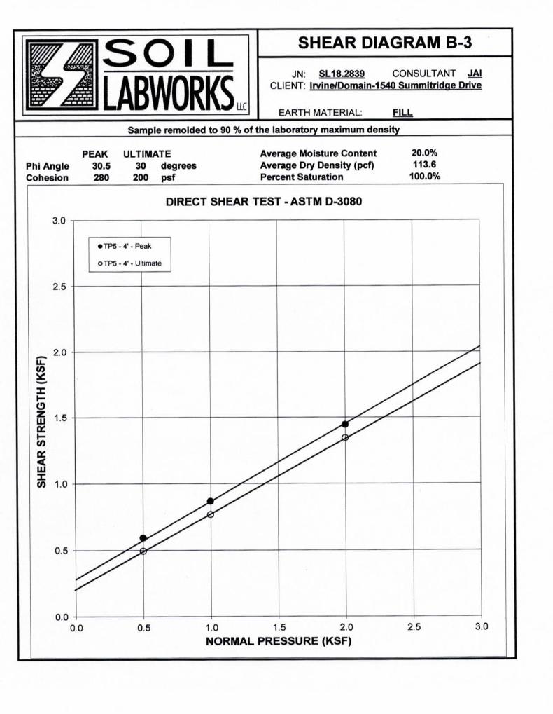
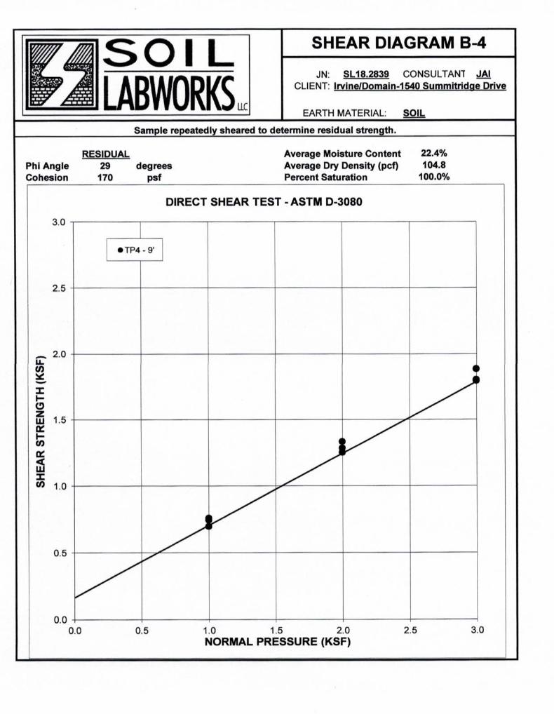
Enc: Appendix I - Laboratory Testing by Soil LabworksMoisture-Density Relationship (Plate A)Shear Test Diagrams (Plates B-1 through B-3)
Appendix II - Test Pit Logs by GHAVicinity MapRegional Geologic MapLog of Test Pits (9 Pages)Calculation Sheets (93)Sections A through ELocal Topo Map
In pocket Geologic Map
xc: (4) Addressee
STATEMENT OF RESPONSIBILITY - SOIL TESTING BY SOIL LABWORKS, LLC
Laboratory testing by Soil Labworks, LLC was performed under the supervision of theundersigned engineer. Irvine Geotechnical and Jon A. Irvine has reviewed referencedlaboratory testing report dated July 12, 2018 and the results appear to be reasonable forthis area of the Santa Monica Mountains. Irvine Geotechnical and the undersigned engineerconcurs with the findings of Soil Labworks, LLC and accepts professional responsibility forutilizing the data.
145 N. Sierra Madre Blvd., Suite #1 • Pasadena • California • 91107 • Phone: 626-844-6641/Fax: 626-604-0394


IC: 17188 CONSULT: JAICLIENT: DOMAEN - SUMMITRIDE
CALCULATION SHEET #
CALCULATION PARAMETERSEARTH MATERIAL: FILL WALL HEIGHT 12 feetSHEAR DIAGRAM: BACKSLOPE ANGLE: 0 degreesCOHESION: 235 psf SURCHARGE: 0 poundsPHI ANGLE: 30 degrees SURCHARGE TYPE: U UniformDENSITY 134 pcf INITIAL FAILURE ANGLE: 30 degreesSAFETY FACTOR: 1 FINAL FAILURE ANGLE: 70 degreesWALL FRICTION 0 degrees INITIAL TENSION CRACK: 2 feetCD (C/FS): 235.0 psf FINAL TENSION CRACK: 100 feetPHID = ATAN(TAN(PHI)/FS) = 30.0 degreesHORIZONTAL PSEUDO STATIC SEISMIC COEFFICIENT (kh) 0.312 %gVERTICAL PSEUDO STATIC SEISMIC COEFFICIENT (kv) 0 %g
CRITICAL FAILURE ANGLE 49 degreesAREA OF TRIAL FAILURE WEDGE 55.8 square feetTOTAL EXTERNAL SURCHARGE 0.0 poundsWEIGHT OF TRIAL FAILURE WEDGE 7479.3 poundsNUMBER OF TRIAL WEDGES ANALYZED 4059 trialsLENGTH OF FAILURE PLANE 10.7 feetDEPTH OF TENSION CRACK 3.9 feetHORIZONTAL DISTANCE TO UPSLOPE TENSION CRACK 7.0 feetCALCULATED HORIZONTAL THRUST ON WALL 2612.3 pounds
RETAINING WALL
THE CALCULATION INDICATES THAT FOR THE DESIGN GROUND MOTION, THE UNBALANCED FORCE ON RETAINING WALLS IS 2.613 KIPS.
CALCULATED RESULTS
CALCULATE THE DESIGN MINIMUM EQUIVALENT FLUID PRESSURE (EFP) FOR PROPOSED RETAINING WALLS. THE WALL HEIGHT AND BACKSLOPE AND SURCHARGE CONDITIONS ARE LISTED BELOW. ASSUME THE BACKFILL IS SATURATED WITH NO EXCESS HYDROSTATIC PRESSURE. USE THE MONONOBE-OKABE METHOD FOR SEISMIC FORCES.
B-1
IC: 17188 CONSULT: JAICLIENT: DOMAEN - SUMMITRIDE
CALCULATION SHEET #
CALCULATION PARAMETERSEARTH MATERIAL: FILL WALL HEIGHT 7 feetSHEAR DIAGRAM: BACKSLOPE ANGLE: 34 degreesCOHESION: 235 psf SURCHARGE: 0 poundsPHI ANGLE: 30 degrees SURCHARGE TYPE: U UniformDENSITY 134 pcf INITIAL FAILURE ANGLE: 30 degreesSAFETY FACTOR: 1 FINAL FAILURE ANGLE: 70 degreesWALL FRICTION 0 degrees INITIAL TENSION CRACK: 2 feetCD (C/FS): 235.0 psf FINAL TENSION CRACK: 17 feetPHID = ATAN(TAN(PHI)/FS) = 30.0 degreesHORIZONTAL PSEUDO STATIC SEISMIC COEFFICIENT (kh) 0.312 %gVERTICAL PSEUDO STATIC SEISMIC COEFFICIENT (kv) 0 %g
CRITICAL FAILURE ANGLE 35 degreesAREA OF TRIAL FAILURE WEDGE 115.3 square feetTOTAL EXTERNAL SURCHARGE 0.0 poundsWEIGHT OF TRIAL FAILURE WEDGE 15448.4 poundsNUMBER OF TRIAL WEDGES ANALYZED 656 trialsLENGTH OF FAILURE PLANE 20.8 feetDEPTH OF TENSION CRACK 6.6 feetHORIZONTAL DISTANCE TO UPSLOPE TENSION CRACK 17.0 feetCALCULATED HORIZONTAL THRUST ON WALL 1931.7 pounds
RETAINING WALL
THE CALCULATION INDICATES THAT FOR THE DESIGN GROUND MOTION, THE UNBALANCED FORCE ON RETAINING WALLS IS 1.932 KIPS.
CALCULATED RESULTS
CALCULATE THE DESIGN MINIMUM EQUIVALENT FLUID PRESSURE (EFP) FOR PROPOSED RETAINING WALLS. THE WALL HEIGHT AND BACKSLOPE AND SURCHARGE CONDITIONS ARE LISTED BELOW. ASSUME THE BACKFILL IS SATURATED WITH NO EXCESS HYDROSTATIC PRESSURE. USE THE MONONOBE-OKABE METHOD FOR SEISMIC FORCES.
B-1
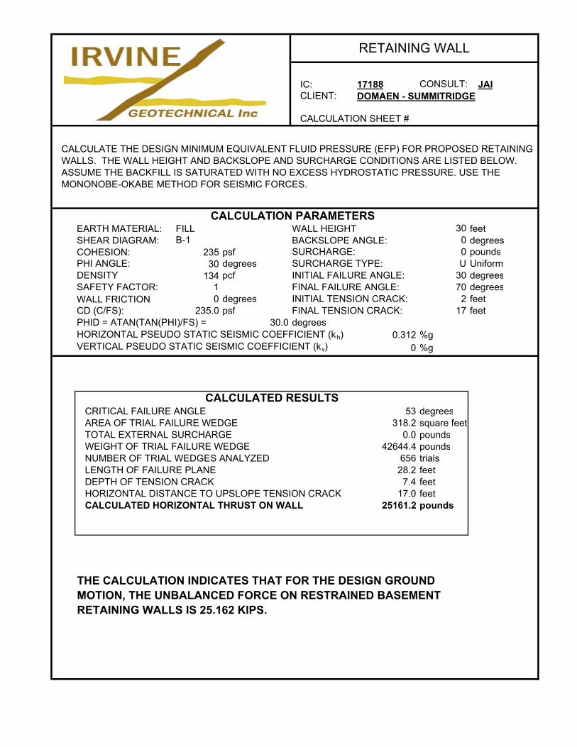
IC: 17188 CONSULT: JAICLIENT: DOMAEN - SUMMITRIDGE
CALCULATION SHEET #
CALCULATION PARAMETERSEARTH MATERIAL: FILL WALL HEIGHT 30 feetSHEAR DIAGRAM: BACKSLOPE ANGLE: 0 degreesCOHESION: 235 psf SURCHARGE: 0 poundsPHI ANGLE: 30 degrees SURCHARGE TYPE: U UniformDENSITY 134 pcf INITIAL FAILURE ANGLE: 30 degreesSAFETY FACTOR: 1 FINAL FAILURE ANGLE: 70 degreesWALL FRICTION 0 degrees INITIAL TENSION CRACK: 2 feetCD (C/FS): 235.0 psf FINAL TENSION CRACK: 17 feetPHID = ATAN(TAN(PHI)/FS) = 30.0 degreesHORIZONTAL PSEUDO STATIC SEISMIC COEFFICIENT (kh) 0.312 %gVERTICAL PSEUDO STATIC SEISMIC COEFFICIENT (kv) 0 %g
CRITICAL FAILURE ANGLE 53 degreesAREA OF TRIAL FAILURE WEDGE 318.2 square feetTOTAL EXTERNAL SURCHARGE 0.0 poundsWEIGHT OF TRIAL FAILURE WEDGE 42644.4 poundsNUMBER OF TRIAL WEDGES ANALYZED 656 trialsLENGTH OF FAILURE PLANE 28.2 feetDEPTH OF TENSION CRACK 7.4 feetHORIZONTAL DISTANCE TO UPSLOPE TENSION CRACK 17.0 feetCALCULATED HORIZONTAL THRUST ON WALL 25161.2 pounds
RETAINING WALL
THE CALCULATION INDICATES THAT FOR THE DESIGN GROUND MOTION, THE UNBALANCED FORCE ON RESTRAINED BASEMENT RETAINING WALLS IS 25.162 KIPS.
CALCULATED RESULTS
CALCULATE THE DESIGN MINIMUM EQUIVALENT FLUID PRESSURE (EFP) FOR PROPOSED RETAINING WALLS. THE WALL HEIGHT AND BACKSLOPE AND SURCHARGE CONDITIONS ARE LISTED BELOW. ASSUME THE BACKFILL IS SATURATED WITH NO EXCESS HYDROSTATIC PRESSURE. USE THE MONONOBE-OKABE METHOD FOR SEISMIC FORCES.
B-1
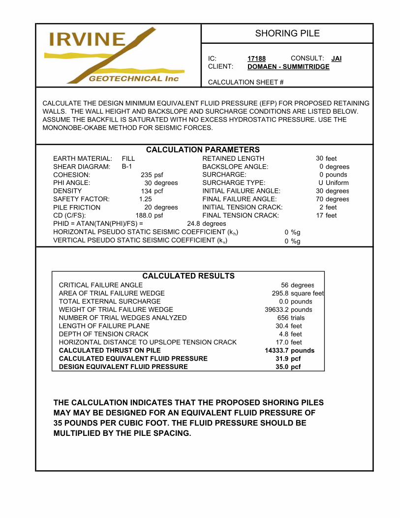
IC: 17188 CONSULT: JAICLIENT: DOMAEN - SUMMITRIDGE
CALCULATION SHEET #
CALCULATION PARAMETERSEARTH MATERIAL: FILL RETAINED LENGTH 30 feetSHEAR DIAGRAM: BACKSLOPE ANGLE: 0 degreesCOHESION: 235 psf SURCHARGE: 0 poundsPHI ANGLE: 30 degrees SURCHARGE TYPE: U UniformDENSITY 134 pcf INITIAL FAILURE ANGLE: 30 degreesSAFETY FACTOR: 1.25 FINAL FAILURE ANGLE: 70 degreesPILE FRICTION 20 degrees INITIAL TENSION CRACK: 2 feetCD (C/FS): 188.0 psf FINAL TENSION CRACK: 17 feetPHID = ATAN(TAN(PHI)/FS) = 24.8 degreesHORIZONTAL PSEUDO STATIC SEISMIC COEFFICIENT (kh) 0 %gVERTICAL PSEUDO STATIC SEISMIC COEFFICIENT (kv) 0 %g
CRITICAL FAILURE ANGLE 56 degreesAREA OF TRIAL FAILURE WEDGE 295.8 square feetTOTAL EXTERNAL SURCHARGE 0.0 poundsWEIGHT OF TRIAL FAILURE WEDGE 39633.2 poundsNUMBER OF TRIAL WEDGES ANALYZED 656 trialsLENGTH OF FAILURE PLANE 30.4 feetDEPTH OF TENSION CRACK 4.8 feetHORIZONTAL DISTANCE TO UPSLOPE TENSION CRACK 17.0 feetCALCULATED THRUST ON PILE 14333.7 poundsCALCULATED EQUIVALENT FLUID PRESSURE 31.9 pcfDESIGN EQUIVALENT FLUID PRESSURE 35.0 pcf
SHORING PILE
THE CALCULATION INDICATES THAT THE PROPOSED SHORING PILES MAY MAY BE DESIGNED FOR AN EQUIVALENT FLUID PRESSURE OF 35 POUNDS PER CUBIC FOOT. THE FLUID PRESSURE SHOULD BE MULTIPLIED BY THE PILE SPACING.
CALCULATED RESULTS
CALCULATE THE DESIGN MINIMUM EQUIVALENT FLUID PRESSURE (EFP) FOR PROPOSED RETAINING WALLS. THE WALL HEIGHT AND BACKSLOPE AND SURCHARGE CONDITIONS ARE LISTED BELOW. ASSUME THE BACKFILL IS SATURATED WITH NO EXCESS HYDROSTATIC PRESSURE. USE THE MONONOBE-OKABE METHOD FOR SEISMIC FORCES.
B-1
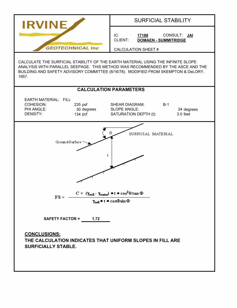
IC: 17188 CONSULT: JAICLIENT: DOMAEN - SUMMITRIDGE
CALCULATION SHEET #
CALCULATION PARAMETERS
EARTH MATERIAL: FILLCOHESION: 235 psf SHEAR DIAGRAM: B-1PHI ANGLE: 30 degrees SLOPE ANGLE: 34 degreesDENSITY: 134 pcf SATURATION DEPTH (t): 3.0 feet
SAFETY FACTOR = 1.72
CONCLUSIONS:
SURFICIAL STABILITY
THE CALCULATION INDICATES THAT UNIFORM SLOPES IN FILL ARE SURFICIALLY STABLE.
CALCULATE THE SURFICIAL STABILITY OF THE EARTH MATERIAL USING THE INFINITE SLOPE ANALYSIS WITH PARALLEL SEEPAGE. THIS METHOD WAS RECOMMENDED BY THE ASCE AND THE BUILDING AND SAFETY ADVISORY COMMITTEE (8/16/78). MODIFIED FROM SKEMPTON & DeLORY, 1957.
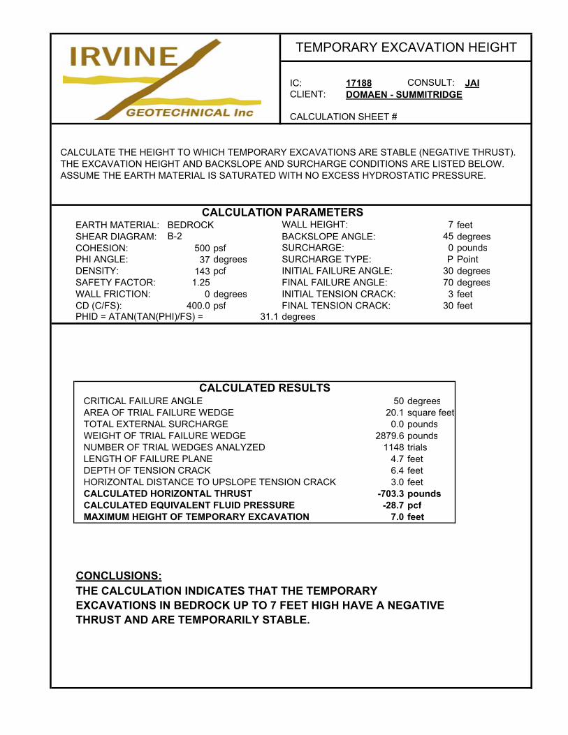
IC: 17188 CONSULT: JAICLIENT: DOMAEN - SUMMITRIDGE
CALCULATION SHEET #
CALCULATION PARAMETERSEARTH MATERIAL: BEDROCK WALL HEIGHT: 7 feetSHEAR DIAGRAM: BACKSLOPE ANGLE: 45 degreesCOHESION: 500 psf SURCHARGE: 0 poundsPHI ANGLE: 37 degrees SURCHARGE TYPE: P PointDENSITY: 143 pcf INITIAL FAILURE ANGLE: 30 degreesSAFETY FACTOR: 1.25 FINAL FAILURE ANGLE: 70 degreesWALL FRICTION: 0 degrees INITIAL TENSION CRACK: 3 feetCD (C/FS): 400.0 psf FINAL TENSION CRACK: 30 feetPHID = ATAN(TAN(PHI)/FS) = 31.1 degrees
CRITICAL FAILURE ANGLE 50 degreesAREA OF TRIAL FAILURE WEDGE 20.1 square feetTOTAL EXTERNAL SURCHARGE 0.0 poundsWEIGHT OF TRIAL FAILURE WEDGE 2879.6 poundsNUMBER OF TRIAL WEDGES ANALYZED 1148 trialsLENGTH OF FAILURE PLANE 4.7 feetDEPTH OF TENSION CRACK 6.4 feetHORIZONTAL DISTANCE TO UPSLOPE TENSION CRACK 3.0 feetCALCULATED HORIZONTAL THRUST -703.3 poundsCALCULATED EQUIVALENT FLUID PRESSURE -28.7 pcfMAXIMUM HEIGHT OF TEMPORARY EXCAVATION 7.0 feet
CONCLUSIONS:
TEMPORARY EXCAVATION HEIGHT
THE CALCULATION INDICATES THAT THE TEMPORARY EXCAVATIONS IN BEDROCK UP TO 7 FEET HIGH HAVE A NEGATIVE THRUST AND ARE TEMPORARILY STABLE.
CALCULATED RESULTS
CALCULATE THE HEIGHT TO WHICH TEMPORARY EXCAVATIONS ARE STABLE (NEGATIVE THRUST). THE EXCAVATION HEIGHT AND BACKSLOPE AND SURCHARGE CONDITIONS ARE LISTED BELOW. ASSUME THE EARTH MATERIAL IS SATURATED WITH NO EXCESS HYDROSTATIC PRESSURE.
B-2
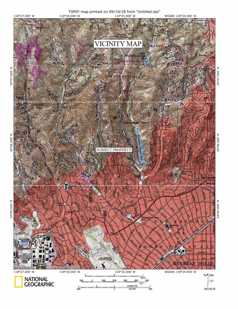
WGS84 118°24.000' W
WGS84 118°24.000' W
118°25.000' W
118°25.000' W
118°26.000' W
118°26.000' W
118°27.000' W
118°27.000' W
34°0
5.0
00' N
34°0
5.0
00' N
34°0
6.0
00' N
34°0
6.0
00' N
34°0
7.0
00' N
34°0
7.0
00' N
Map created with Map created with Map created with Map created with Map created with Map created with Map created with Map created with Map created with TOPO!®TOPO!®TOPO!®TOPO!®TOPO!®TOPO!®TOPO!®TOPO!®TOPO!® ©2007 National Geographic ©2007 National Geographic ©2007 National Geographic ©2007 National Geographic ©2007 National Geographic ©2007 National Geographic ©2007 National Geographic ©2007 National Geographic ©2007 National Geographic
TOPO! map printed on 09/19/18 from "Untitled.tpo"
09/19/18
TN MN
12°
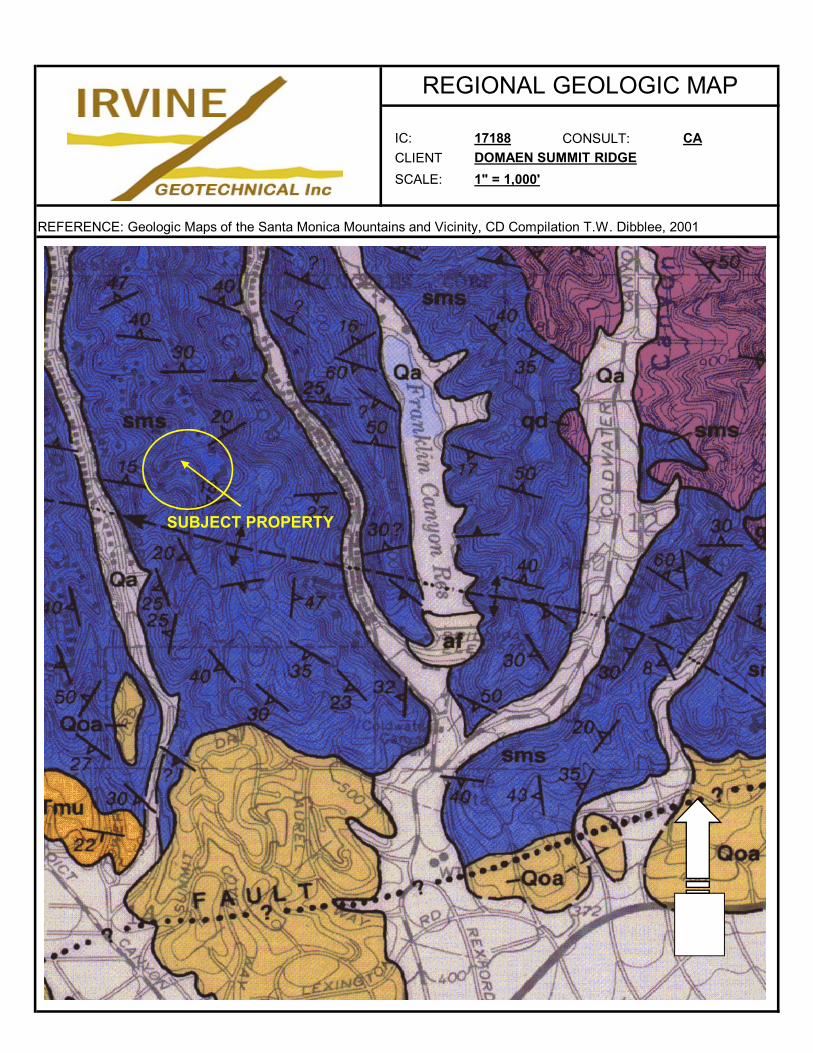
IC: 17188 CONSULT: CA
CLIENT DOMAEN SUMMIT RIDGE
SCALE: 1" = 1,000'
REFERENCE: Geologic Maps of the Santa Monica Mountains and Vicinity, CD Compilation T.W. Dibblee, 2001
REGIONAL GEOLOGIC MAP
SUBJECT PROPERTY
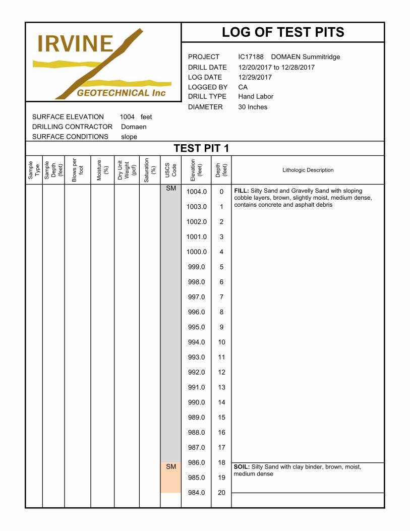
IC17188 DOMAEN Summitridge
12/20/2017 to 12/28/2017
12/29/2017
CAHand Labor
30 Inches
SURFACE ELEVATION 1004 feet
DRILLING CONTRACTOR Domaen
SURFACE CONDITIONS
Sam
ple
Typ
e
Sam
ple
Dep
th
(fee
t)
Blo
ws
per
foot
Moi
stur
e (%
)
Dry
Uni
t W
eigh
t (p
cf)
Sat
urat
ion
(%)
US
CS
C
ode
Ele
vatio
n (f
eet)
Dep
th
(fee
t)
Lithologic Description
SM
SM
LOG OF TEST PITS
PROJECT
DRILL DATE
LOG DATE
LOGGED BYDRILL TYPE
DIAMETER
slope
TEST PIT 1
1004.0 0
1003.0 1
1002.0 2
1001.0 3
1000.0 4
999.0 5
998.0 6
997.0 7
996.0 8
995.0 9
994.0 10
993.0 11
992.0 12
991.0 13
990.0 14
989.0 15
988.0 16
987.0 17
986.0 18
985.0 19
984.0 20
FILL: Silty Sand and Gravelly Sand with sloping cobble layers, brown, slightly moist, medium dense, contains concrete and asphalt debris
SOIL: Silty Sand with clay binder, brown, moist, medium dense
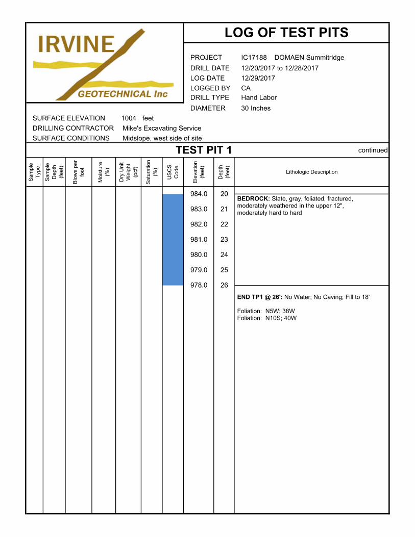
IC17188 DOMAEN Summitridge
12/20/2017 to 12/28/2017
12/29/2017
CAHand Labor
30 Inches
SURFACE ELEVATION 1004 feet
DRILLING CONTRACTOR Mike's Excavating Service
SURFACE CONDITIONS
continued
Sam
ple
Typ
e
Sam
ple
Dep
th
(fee
t)
Blo
ws
per
foot
Moi
stur
e (%
)
Dry
Uni
t W
eigh
t (p
cf)
Sat
urat
ion
(%)
US
CS
C
ode
Ele
vatio
n (f
eet)
Dep
th
(fee
t)
Lithologic Description
LOG OF TEST PITS
PROJECT
DRILL DATE
LOG DATE
LOGGED BYDRILL TYPE
DIAMETER
Midslope, west side of site
TEST PIT 1
984.0 20
983.0 21
982.0 22
981.0 23
980.0 24
979.0 25
978.0 26
END TP1 @ 26': No Water; No Caving; Fill to 18'
Foliation: N5W; 38WFoliation: N10S; 40W
BEDROCK: Slate, gray, foliated, fractured, moderately weathered in the upper 12", moderately hard to hard

IC17188 DOMAEN Summitridge
1/9/2018 to 1-10-2018
1/10/2018
CAHand Labor
30 Inches
SURFACE ELEVATION 1008 feet
DRILLING CONTRACTOR Mike's Excavating Service
SURFACE CONDITIONS
Sam
ple
Typ
e
Sam
ple
Dep
th
(fee
t)
Blo
ws
per
foot
Moi
stur
e (%
)
Dry
Uni
t W
eigh
t (p
cf)
Sat
urat
ion
(%)
US
CS
C
ode
Ele
vatio
n (f
eet)
Dep
th
(fee
t)
Lithologic Description
SM
SM
LOG OF TEST PITS
PROJECT
DRILL DATE
LOG DATE
LOGGED BYDRILL TYPE
DIAMETER
Western portion of existing level bench
TEST PIT 2
1008.0 0
1007.0 1
1006.0 2
1005.0 3
1004.0 4
1003.0 5
1002.0 6
1001.0 7
1000.0 8
999.0 9
998.0 10
997.0 11 END TP2 @ 10': No Water; No Caving; Fill to 5'
Foliation: N5W; 35WFoliation: N10W; 40WFoliation: N25E; 45W
FILL: Silty Sand with gravel, brown, slightly moist, medium dense, contains concrete and asphalt debris
SOIL: Silty Sand with gravel, gray-brown, moist, medium dense
BEDROCK: Slate, blue-gray, fractured, hard, moderately weathered
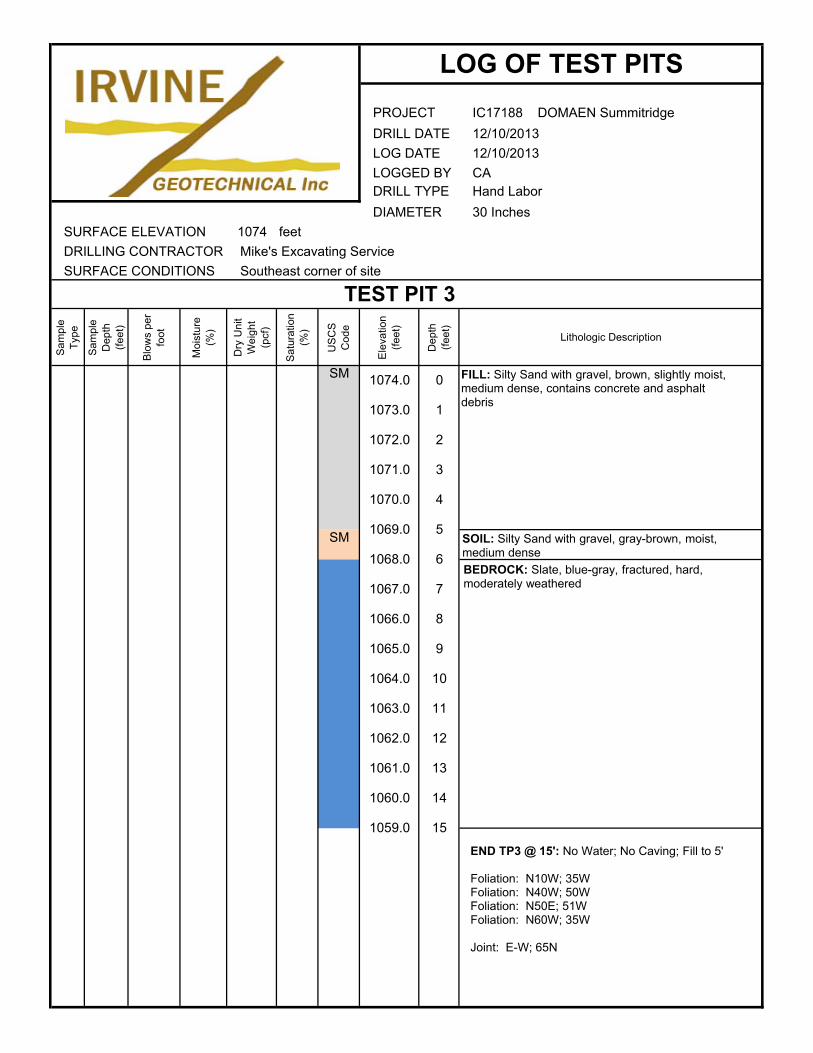
IC17188 DOMAEN Summitridge
12/10/2013
12/10/2013
CAHand Labor
30 Inches
SURFACE ELEVATION 1074 feet
DRILLING CONTRACTOR Mike's Excavating Service
SURFACE CONDITIONS
Sam
ple
Typ
e
Sam
ple
Dep
th
(fee
t)
Blo
ws
per
foot
Moi
stur
e (%
)
Dry
Uni
t W
eigh
t (p
cf)
Sat
urat
ion
(%)
US
CS
C
ode
Ele
vatio
n (f
eet)
Dep
th
(fee
t)
Lithologic Description
SM
SM
LOG OF TEST PITS
PROJECT
DRILL DATE
LOG DATE
LOGGED BYDRILL TYPE
DIAMETER
Southeast corner of site
TEST PIT 3
1074.0 0
1073.0 1
1072.0 2
1071.0 3
1070.0 4
1069.0 5
1068.0 6
1067.0 7
1066.0 8
1065.0 9
1064.0 10
1063.0 11
1062.0 12
1061.0 13
1060.0 14
1059.0 15
END TP3 @ 15': No Water; No Caving; Fill to 5'
Foliation: N10W; 35WFoliation: N40W; 50WFoliation: N50E; 51WFoliation: N60W; 35W
Joint: E-W; 65N
FILL: Silty Sand with gravel, brown, slightly moist, medium dense, contains concrete and asphalt debris
SOIL: Silty Sand with gravel, gray-brown, moist, medium dense
BEDROCK: Slate, blue-gray, fractured, hard, moderately weathered
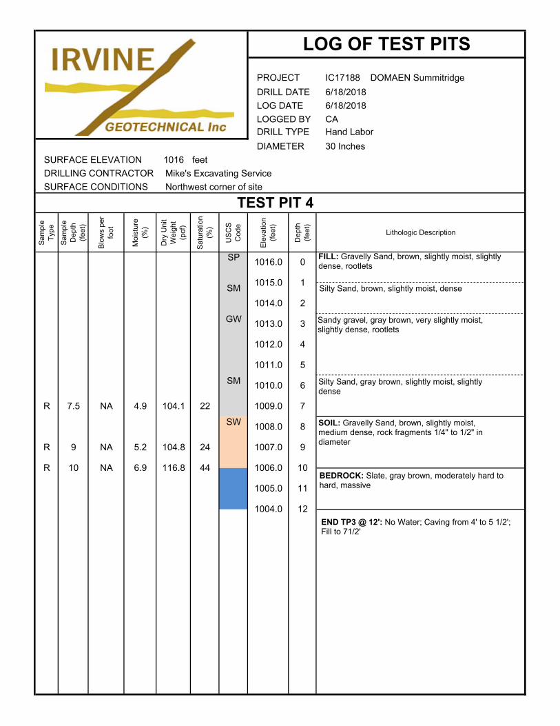
IC17188 DOMAEN Summitridge
6/18/2018
6/18/2018
CAHand Labor
30 Inches
SURFACE ELEVATION 1016 feet
DRILLING CONTRACTOR Mike's Excavating Service
SURFACE CONDITIONS
Sam
ple
Typ
e
Sam
ple
Dep
th
(fee
t)
Blo
ws
per
foot
Moi
stur
e (%
)
Dry
Uni
t W
eigh
t (p
cf)
Sat
urat
ion
(%)
US
CS
C
ode
Ele
vatio
n (f
eet)
Dep
th
(fee
t)
Lithologic Description
SP
SM
GW
SM
SW
LOG OF TEST PITS
PROJECT
DRILL DATE
LOG DATE
LOGGED BYDRILL TYPE
DIAMETER
Northwest corner of site
TEST PIT 4
1016.0 0
1015.0 1
1014.0 2
1013.0 3
1012.0 4
1011.0 5
1010.0 6
1009.0 7
1008.0 8
R 7.5 NA 4.9 104.1 22
1007.0 9
R 10 NA 6.9 116.8 44 1006.0 10
R 9 NA 5.2 104.8 24
1005.0 11
1004.0 12
Silty Sand, brown, slightly moist, dense
END TP3 @ 12': No Water; Caving from 4' to 5 1/2'; Fill to 71/2'
FILL: Gravelly Sand, brown, slightly moist, slightly dense, rootlets
BEDROCK: Slate, gray brown, moderately hard to hard, massive
SOIL: Gravelly Sand, brown, slightly moist, medium dense, rock fragments 1/4" to 1/2" in diameter
Sandy gravel, gray brown, very slightly moist, slightly dense, rootlets
Silty Sand, gray brown, slightly moist, slightly dense
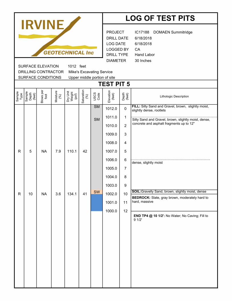
IC17188 DOMAEN Summitridge
6/18/2018
6/18/2018
CAHand Labor
30 Inches
SURFACE ELEVATION 1012 feet
DRILLING CONTRACTOR Mike's Excavating Service
SURFACE CONDITIONS
Sam
ple
Typ
e
Sam
ple
Dep
th
(fee
t)
Blo
ws
per
foot
Moi
stur
e (%
)
Dry
Uni
t W
eigh
t (p
cf)
Sat
urat
ion
(%)
US
CS
C
ode
Ele
vatio
n (f
eet)
Dep
th
(fee
t)
Lithologic Description
SM
SM
SW
LOG OF TEST PITS
PROJECT
DRILL DATE
LOG DATE
LOGGED BYDRILL TYPE
DIAMETER
Upper middle portion of site
TEST PIT 5
1012.0 0
1011.0 1
1010.0 2
1009.0 3
1008.0 4
1007.0 5
1006.0 6
R 5 NA 7.9 110.1 42
1005.0 7
1004.0 8
1003.0 9
R 10 NA 3.6 134.1 41 1002.0 10
1001.0 11
1000.0 12
Silty Sand and Gravel, brown, slightly moist, dense, concrete and asphalt fragments up to 12"
END TP4 @ 10 1/2': No Water; No Caving; Fill to 9 1/2'
FILL: Silty Sand and Gravel, brown, slightly moist, slightly dense, rootlets
BEDROCK: Slate, gray brown, moderately hard to hard, massive
SOIL:Gravelly Sand, brown, slightly moist, dense
dense, slightly moist
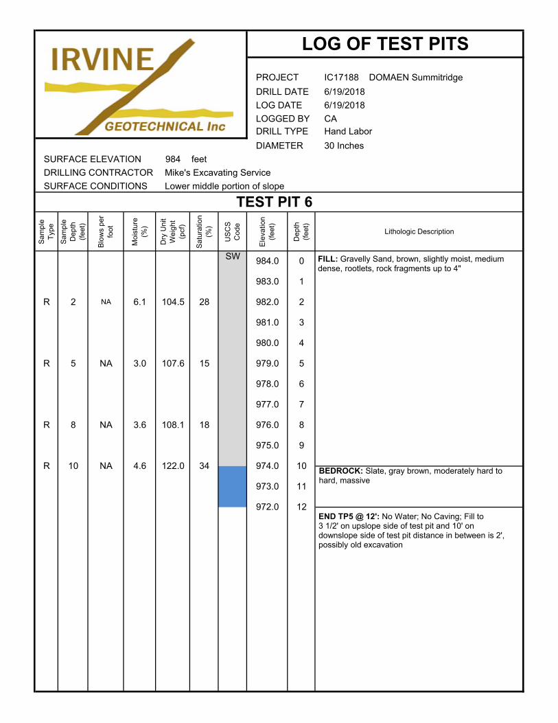
IC17188 DOMAEN Summitridge
6/19/2018
6/19/2018
CAHand Labor
30 Inches
SURFACE ELEVATION 984 feet
DRILLING CONTRACTOR Mike's Excavating Service
SURFACE CONDITIONS
Sam
ple
Typ
e
Sam
ple
Dep
th
(fee
t)
Blo
ws
per
foot
Moi
stur
e (%
)
Dry
Uni
t W
eigh
t (p
cf)
Sat
urat
ion
(%)
US
CS
C
ode
Ele
vatio
n (f
eet)
Dep
th
(fee
t)
Lithologic Description
SW
973.0 11
972.0 12
975.0 9
R 10 NA 4.6 122.0 34 974.0 10
977.0 7
R 8 NA 3.6 108.1 18 976.0 8
979.0 5
978.0 6
R 5 NA 3.0 107.6 15
981.0 3
980.0 4
983.0 1
R 2 NA 6.1 104.5 28 982.0 2
Lower middle portion of slope
TEST PIT 6
984.0 0
DRILL DATE
LOG DATE
LOGGED BYDRILL TYPE
DIAMETER
LOG OF TEST PITS
PROJECT
END TP5 @ 12': No Water; No Caving; Fill to 3 1/2' on upslope side of test pit and 10' on downslope side of test pit distance in between is 2', possibly old excavation
FILL: Gravelly Sand, brown, slightly moist, medium dense, rootlets, rock fragments up to 4"
BEDROCK: Slate, gray brown, moderately hard to hard, massive
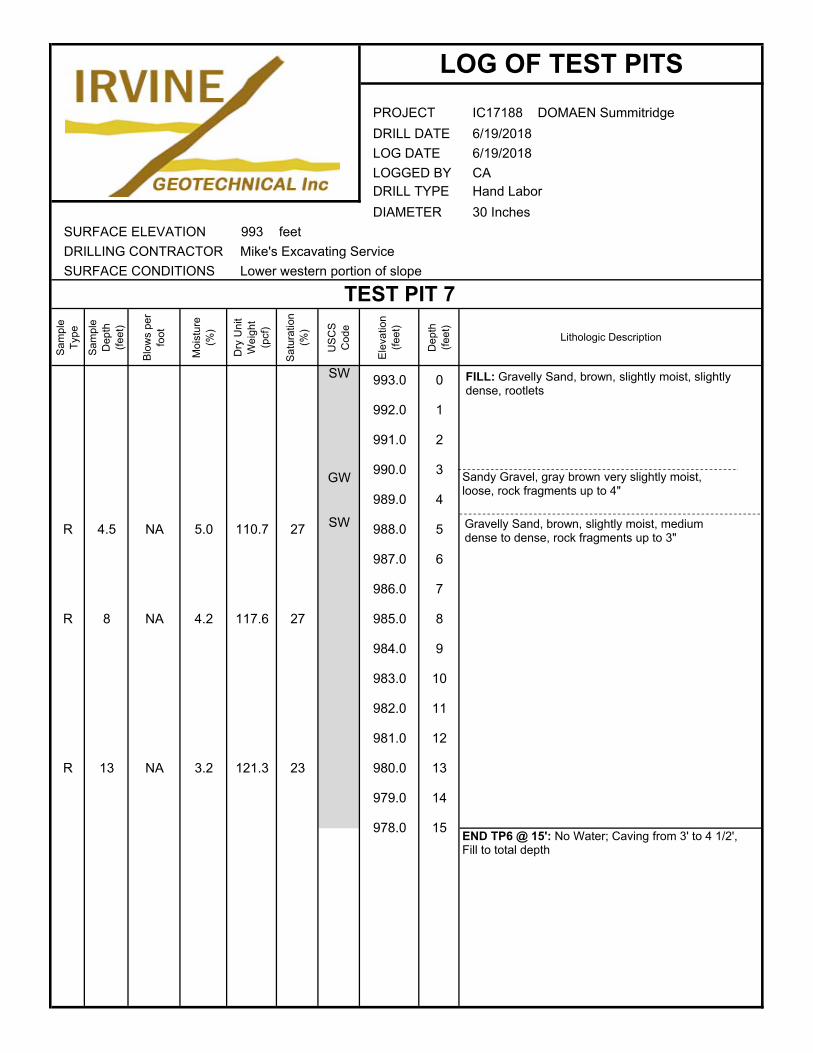
IC17188 DOMAEN Summitridge
6/19/2018
6/19/2018
CAHand Labor
30 Inches
SURFACE ELEVATION 993 feet
DRILLING CONTRACTOR Mike's Excavating Service
SURFACE CONDITIONS
Sam
ple
Typ
e
Sam
ple
Dep
th
(fee
t)
Blo
ws
per
foot
Moi
stur
e (%
)
Dry
Uni
t W
eigh
t (p
cf)
Sat
urat
ion
(%)
US
CS
C
ode
Ele
vatio
n (f
eet)
Dep
th
(fee
t)
Lithologic Description
SW
GW
SW
978.0 15
980.0 13
979.0 14
R 13 NA 3.2 121.3 23
982.0 11
981.0 12
984.0 9
983.0 10
986.0 7
R 8 NA 4.2 117.6 27 985.0 8
988.0 5
987.0 6
R 4.5 NA 5.0 110.7 27
990.0 3
989.0 4
992.0 1
991.0 2
Lower western portion of slope
TEST PIT 7
993.0 0
DRILL DATE
LOG DATE
LOGGED BYDRILL TYPE
DIAMETER
LOG OF TEST PITS
PROJECT
END TP6 @ 15': No Water; Caving from 3' to 4 1/2', Fill to total depth
FILL: Gravelly Sand, brown, slightly moist, slightly dense, rootlets
Gravelly Sand, brown, slightly moist, medium dense to dense, rock fragments up to 3"
Sandy Gravel, gray brown very slightly moist, loose, rock fragments up to 4"
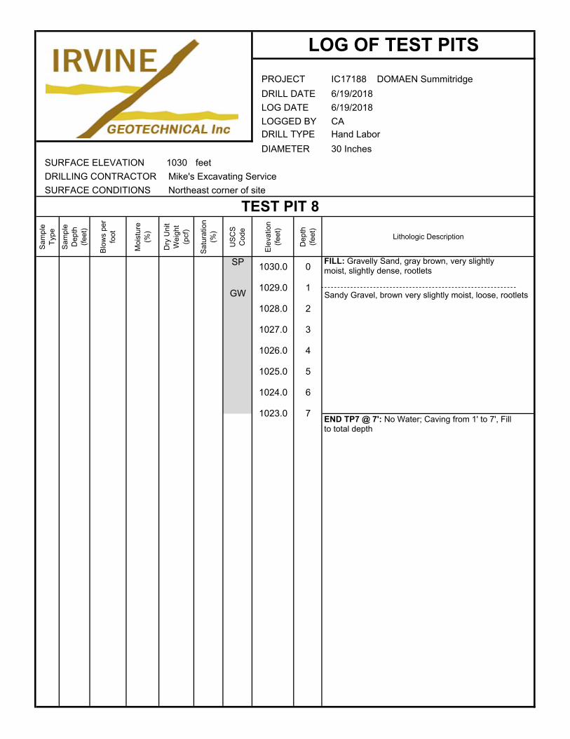
IC17188 DOMAEN Summitridge
6/19/2018
6/19/2018
CAHand Labor
30 Inches
SURFACE ELEVATION 1030 feet
DRILLING CONTRACTOR Mike's Excavating Service
SURFACE CONDITIONS
Sam
ple
Typ
e
Sam
ple
Dep
th
(fee
t)
Blo
ws
per
foot
Moi
stur
e (%
)
Dry
Uni
t W
eigh
t (p
cf)
Sat
urat
ion
(%)
US
CS
C
ode
Ele
vatio
n (f
eet)
Dep
th
(fee
t)
Lithologic Description
SP
GW
1023.0 7
1025.0 5
1024.0 6
1027.0 3
1026.0 4
1029.0 1
1028.0 2
Northeast corner of site
TEST PIT 8
1030.0 0
DRILL DATE
LOG DATE
LOGGED BYDRILL TYPE
DIAMETER
LOG OF TEST PITS
PROJECT
END TP7 @ 7': No Water; Caving from 1' to 7', Fill to total depth
FILL: Gravelly Sand, gray brown, very slightly moist, slightly dense, rootlets
Sandy Gravel, brown very slightly moist, loose, rootlets
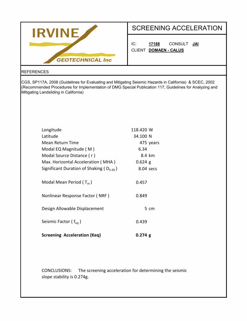
IC: 17188 CONSULT JAI
CLIENT DOMAEN - CALUS
REFERENCES
Longitude 118.420 W
Latitude 34.100 N
Mean Return Time 475 years
Modal EQ Magnitude ( M ) 6.34
Modal Source Distance ( r ) 8.4 km
Max. Horizontal Acceleration ( MHA ) 0.624 g
Significant Duration of Shaking ( D5‐95 ) 8.04 secs
Modal Mean Period ( Tm ) 0.457
Nonlinear Response Factor ( NRF ) 0.849
Design Allowable Displacement 5 cm
Seismic Factor ( feq ) 0.439
Screening Acceleration (Keq) 0.274 g
SCREENING ACCELERATION
CGS, SP117A, 2008 (Guidelines for Evaluating and Mitigating Seismic Hazards in California) & SCEC, 2002 (Recommended Procedures for Implementation of DMG Special Publication 117, Guidelines for Analyzing and Mitigating Landsliding in California)
CONCLUSIONS: The screening acceleration for determining the seismic
slope stability is 0.274g.
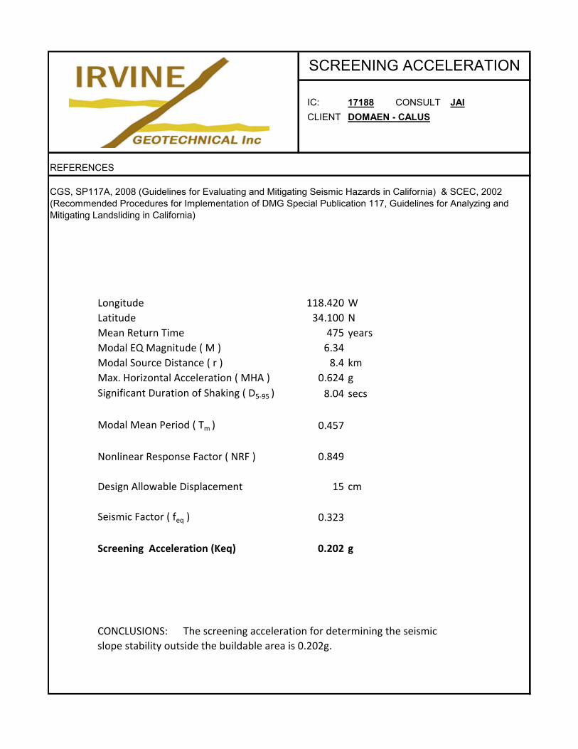
IC: 17188 CONSULT JAI
CLIENT DOMAEN - CALUS
REFERENCES
Longitude 118.420 W
Latitude 34.100 N
Mean Return Time 475 years
Modal EQ Magnitude ( M ) 6.34
Modal Source Distance ( r ) 8.4 km
Max. Horizontal Acceleration ( MHA ) 0.624 g
Significant Duration of Shaking ( D5‐95 ) 8.04 secs
Modal Mean Period ( Tm ) 0.457
Nonlinear Response Factor ( NRF ) 0.849
Design Allowable Displacement 15 cm
Seismic Factor ( feq ) 0.323
Screening Acceleration (Keq) 0.202 g
SCREENING ACCELERATION
CGS, SP117A, 2008 (Guidelines for Evaluating and Mitigating Seismic Hazards in California) & SCEC, 2002 (Recommended Procedures for Implementation of DMG Special Publication 117, Guidelines for Analyzing and Mitigating Landsliding in California)
CONCLUSIONS: The screening acceleration for determining the seismic
slope stability outside the buildable area is 0.202g.
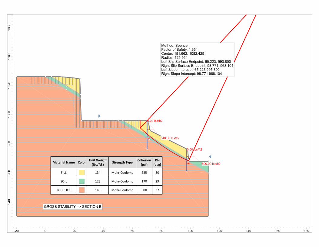
0.00 lbs/ft2
600.00 lbs/ft2
0.00 lbs/ft2
540.00 lbs/ft2
Material Name ColorUnit Weight(lbs/ 3)
Strength TypeCohesion(psf)
Phi(deg)
FILL 134 Mohr‐Coulomb 235 30
SOIL 128 Mohr‐Coulomb 170 29
BEDROCK 143 Mohr‐Coulomb 500 37
GROSS STABILITY --> SECTION B
Method: SpencerFactor of Safety: 1.654Center: 151.662, 1082.425Radius: 125.964Left Slip Surface Endpoint: 65.223, 990.800Right Slip Surface Endpoint: 98.771, 968.104Left Slope Intercept: 65.223 995.800Right Slope Intercept: 98.771 968.104
1060
1040
1020
1000
980
960
940
-20 0 20 40 60 80 100 120 140 160 180

Slide Analysis Information
DOMAEN ‐ CALUS ‐ SUMMITRIDGE
Project Summary
8.018Slide Modeler Version:
00h:00m:02.62sCompute Time:
General Settings
Imperial UnitsUnits of Measurement:
daysTime Units:
feet/secondPermeability Units:
StandardData Output:
Left to RightFailure Direction:
Analysis Options
VerticalSlices Type:
Analysis Methods Used
Spencer
50Number of slices:
0.005Tolerance:
75Maximum number of iterations:
YesCheck malpha < 0.2:YesCreate Interslice boundaries at intersections
with water tables and piezos:
1Initial trial value of FS:
YesSteffensen Iteration:
Groundwater Analysis
Water SurfacesGroundwater Method:
62.4Pore Fluid Unit Weight [lbs/ft3]:
YesUse negative pore pressure cutoff:
0Maximum negative pore pressure [psf]:
NoneAdvanced Groundwater Method:
Random Numbers
10116Pseudo‐random Seed:
Park and Miller v.3Random Number Generation Method:
Surface Options
: Page 1 of 7SLIDEINTERPRET 8.018
SECTION B CALC.slim
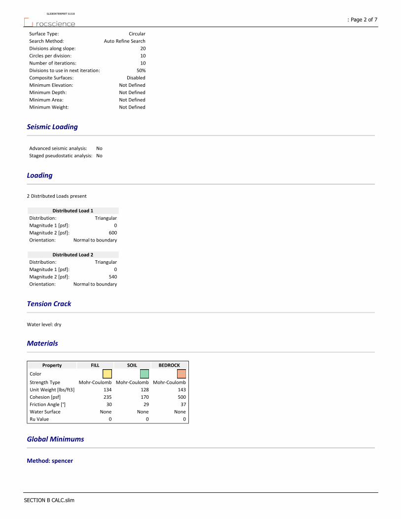
CircularSurface Type:
Auto Refine SearchSearch Method:
20Divisions along slope:
10Circles per division:
10Number of iterations:
50%Divisions to use in next iteration:
DisabledComposite Surfaces:
Not DefinedMinimum Elevation:
Not DefinedMinimum Depth:
Not DefinedMinimum Area:
Not DefinedMinimum Weight:
Seismic Loading
NoAdvanced seismic analysis:
NoStaged pseudostatic analysis:
Loading
2 Distributed Loads present
Distributed Load 1
TriangularDistribution:
0Magnitude 1 [psf]:
600Magnitude 2 [psf]:
Normal to boundaryOrientation:
Distributed Load 2
TriangularDistribution:
0Magnitude 1 [psf]:
540Magnitude 2 [psf]:
Normal to boundaryOrientation:
Tension Crack
Water level: dry
Materials
BEDROCKSOILFILLProperty
Color
Mohr‐CoulombMohr‐CoulombMohr‐CoulombStrength Type
143128134Unit Weight [lbs/ft3]
500170235Cohesion [psf]
372930Friction Angle [°]
NoneNoneNoneWater Surface
000Ru Value
Global Minimums
Method: spencer
: Page 2 of 7SLIDEINTERPRET 8.018
SECTION B CALC.slim
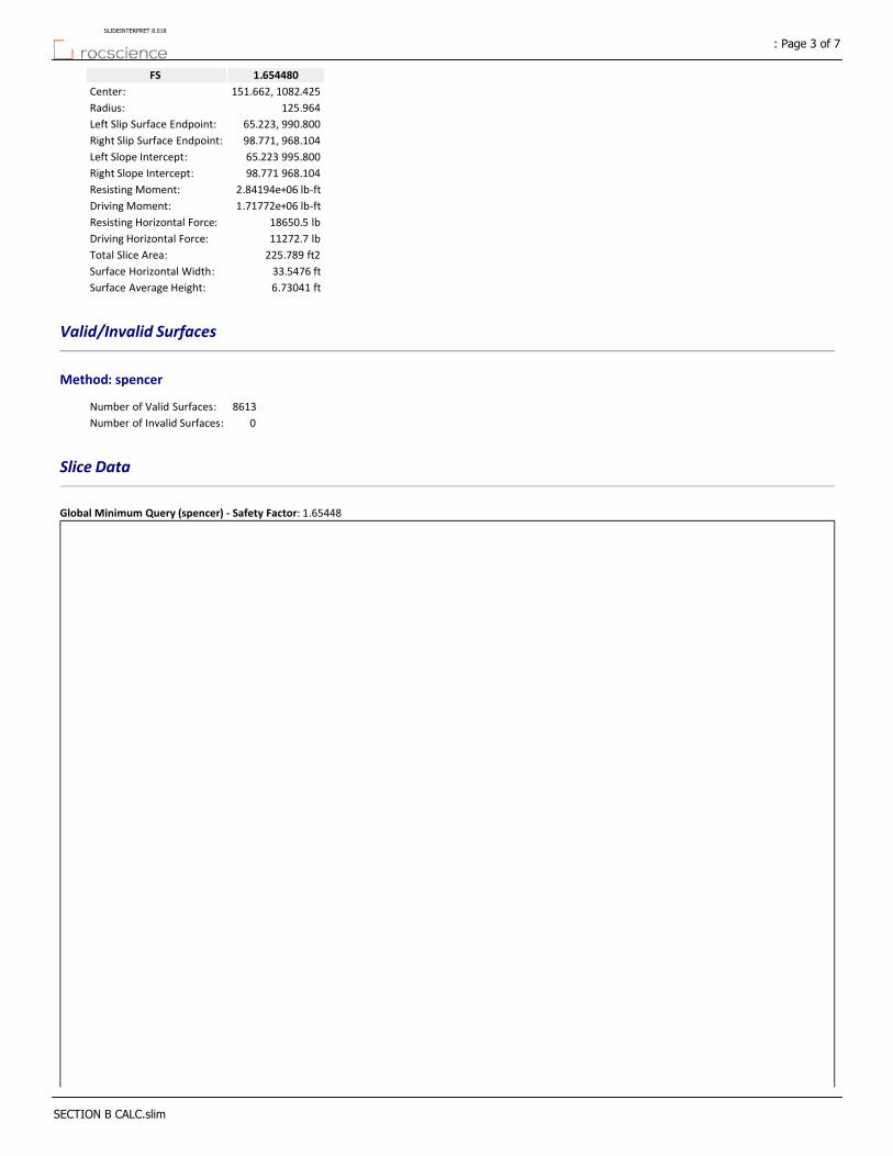
1.654480FS
151.662, 1082.425Center:
125.964Radius:
65.223, 990.800Left Slip Surface Endpoint:
98.771, 968.104Right Slip Surface Endpoint:
65.223 995.800Left Slope Intercept:
98.771 968.104Right Slope Intercept:
2.84194e+06 lb‐ftResisting Moment:
1.71772e+06 lb‐ftDriving Moment:
18650.5 lbResisting Horizontal Force:
11272.7 lbDriving Horizontal Force:
225.789 ft2Total Slice Area:
33.5476 ftSurface Horizontal Width:
6.73041 ftSurface Average Height:
Valid/Invalid Surfaces
Method: spencer
8613Number of Valid Surfaces:
0Number of Invalid Surfaces:
Slice Data
Global Minimum Query (spencer) ‐ Safety Factor: 1.65448
: Page 3 of 7SLIDEINTERPRET 8.018
SECTION B CALC.slim
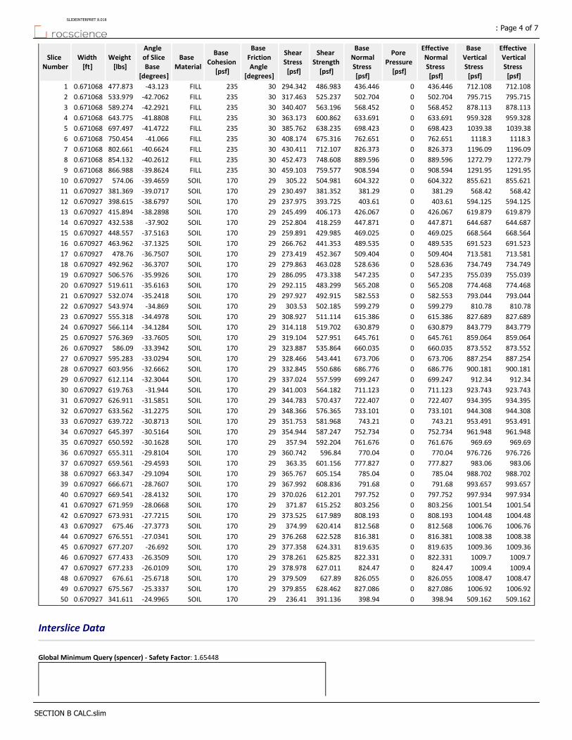
Effective Vertical Stress [psf]
Base Vertical Stress [psf]
Effective Normal Stress [psf]
Pore Pressure [psf]
Base Normal Stress [psf]
Shear Strength [psf]
Shear Stress [psf]
Base Friction Angle
[degrees]
Base Cohesion
[psf]
Base Material
Angle of Slice Base
[degrees]
Weight [lbs]
Width [ft]
Slice Number
712.108712.108436.4460436.446486.983294.34230235FILL‐43.123477.8730.6710681
795.715795.715502.7040502.704525.237317.46330235FILL‐42.7062533.9790.6710682
878.113878.113568.4520568.452563.196340.40730235FILL‐42.2921589.2740.6710683
959.328959.328633.6910633.691600.862363.17330235FILL‐41.8808643.7750.6710684
1039.381039.38698.4230698.423638.235385.76230235FILL‐41.4722697.4970.6710685
1118.31118.3762.6510762.651675.316408.17430235FILL‐41.066750.4540.6710686
1196.091196.09826.3730826.373712.107430.41130235FILL‐40.6624802.6610.6710687
1272.791272.79889.5960889.596748.608452.47330235FILL‐40.2612854.1320.6710688
1291.951291.95908.5940908.594759.577459.10330235FILL‐39.8624866.9880.6710689
855.621855.621604.3220604.322504.981305.2229170SOIL‐39.4659574.060.67092710
568.42568.42381.290381.29381.352230.49729170SOIL‐39.0717381.3690.67092711
594.125594.125403.610403.61393.725237.97529170SOIL‐38.6797398.6150.67092712
619.879619.879426.0670426.067406.173245.49929170SOIL‐38.2898415.8940.67092713
644.687644.687447.8710447.871418.259252.80429170SOIL‐37.902432.5380.67092714
668.564668.564469.0250469.025429.985259.89129170SOIL‐37.5163448.5570.67092715
691.523691.523489.5350489.535441.353266.76229170SOIL‐37.1325463.9620.67092716
713.581713.581509.4040509.404452.367273.41929170SOIL‐36.7507478.760.67092717
734.749734.749528.6360528.636463.028279.86329170SOIL‐36.3707492.9620.67092718
755.039755.039547.2350547.235473.338286.09529170SOIL‐35.9926506.5760.67092719
774.468774.468565.2080565.208483.299292.11529170SOIL‐35.6163519.6110.67092720
793.044793.044582.5530582.553492.915297.92729170SOIL‐35.2418532.0740.67092721
810.78810.78599.2790599.279502.185303.5329170SOIL‐34.869543.9740.67092722
827.689827.689615.3860615.386511.114308.92729170SOIL‐34.4978555.3180.67092723
843.779843.779630.8790630.879519.702314.11829170SOIL‐34.1284566.1140.67092724
859.064859.064645.7610645.761527.951319.10429170SOIL‐33.7605576.3690.67092725
873.552873.552660.0350660.035535.864323.88729170SOIL‐33.3942586.090.67092726
887.254887.254673.7060673.706543.441328.46629170SOIL‐33.0294595.2830.67092727
900.181900.181686.7760686.776550.686332.84529170SOIL‐32.6662603.9560.67092728
912.34912.34699.2470699.247557.599337.02429170SOIL‐32.3044612.1140.67092729
923.743923.743711.1230711.123564.182341.00329170SOIL‐31.944619.7630.67092730
934.395934.395722.4070722.407570.437344.78329170SOIL‐31.5851626.9110.67092731
944.308944.308733.1010733.101576.365348.36629170SOIL‐31.2275633.5620.67092732
953.491953.491743.210743.21581.968351.75329170SOIL‐30.8713639.7220.67092733
961.948961.948752.7340752.734587.247354.94429170SOIL‐30.5164645.3970.67092734
969.69969.69761.6760761.676592.204357.9429170SOIL‐30.1628650.5920.67092735
976.726976.726770.040770.04596.84360.74229170SOIL‐29.8104655.3110.67092736
983.06983.06777.8270777.827601.156363.3529170SOIL‐29.4593659.5610.67092737
988.702988.702785.040785.04605.154365.76729170SOIL‐29.1094663.3470.67092738
993.657993.657791.680791.68608.836367.99229170SOIL‐28.7607666.6710.67092739
997.934997.934797.7520797.752612.201370.02629170SOIL‐28.4132669.5410.67092740
1001.541001.54803.2560803.256615.252371.8729170SOIL‐28.0668671.9590.67092741
1004.481004.48808.1930808.193617.989373.52529170SOIL‐27.7215673.9310.67092742
1006.761006.76812.5680812.568620.414374.9929170SOIL‐27.3773675.460.67092743
1008.381008.38816.3810816.381622.528376.26829170SOIL‐27.0341676.5510.67092744
1009.361009.36819.6350819.635624.331377.35829170SOIL‐26.692677.2070.67092745
1009.71009.7822.3310822.331625.825378.26129170SOIL‐26.3509677.4330.67092746
1009.41009.4824.470824.47627.011378.97829170SOIL‐26.0109677.2330.67092747
1008.471008.47826.0550826.055627.89379.50929170SOIL‐25.6718676.610.67092748
1006.921006.92827.0860827.086628.462379.85529170SOIL‐25.3337675.5670.67092749
509.162509.162398.940398.94391.136236.4129170SOIL‐24.9965341.6110.67092750
Interslice Data
Global Minimum Query (spencer) ‐ Safety Factor: 1.65448
: Page 4 of 7SLIDEINTERPRET 8.018
SECTION B CALC.slim
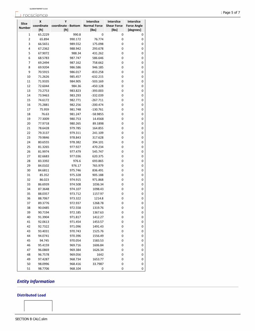
Interslice Force Angle [degrees]
Interslice Shear Force
[lbs]
Interslice Normal Force
[lbs]
Y coordinate ‐ Bottom
[ft]
X coordinate
[ft]
Slice Number
000990.865.22291
0076.774990.17265.8942
00175.098989.55266.56513
00293.678988.94267.23624
00431.262988.3467.90725
00586.646987.74768.57836
00758.662987.16269.24947
00946.185986.58669.92048
00‐833.258986.01770.59159
00‐632.215985.45771.262610
00‐503.169984.90571.933511
00‐450.128984.3672.604412
00‐393.003983.82373.275313
00‐332.039983.29373.946314
00‐267.711982.77174.617215
00‐200.474982.25675.288116
00‐130.761981.74875.95917
00‐58.9855981.24776.6318
0014.4568980.75377.300919
0089.1898980.26577.971820
00164.855979.78578.642821
00241.109979.31179.313722
00317.628978.84379.984623
00394.101978.38280.655524
00470.234977.92781.326525
00545.747977.47981.997426
00620.375977.03682.668327
00693.865976.683.339228
00765.979976.1784.010229
00836.491975.74684.681130
00905.188975.32885.35231
00971.868974.91586.02332
001036.34974.50886.693933
001098.43974.10787.364834
001157.97973.71288.035735
001214.8973.32288.706736
001268.78972.93789.377637
001319.76972.55890.048538
001367.63972.18590.719439
001412.27971.81791.390440
001453.57971.45492.061341
001491.43971.09692.732242
001525.76970.74393.403143
001556.49970.39694.074144
001583.53970.05494.74545
001606.84969.71695.415946
001626.34969.38496.086947
001642969.05696.757848
001653.77968.73497.428749
0033.7987968.41698.099650
000968.10498.770651
Entity Information
Distributed Load
: Page 5 of 7SLIDEINTERPRET 8.018
SECTION B CALC.slim
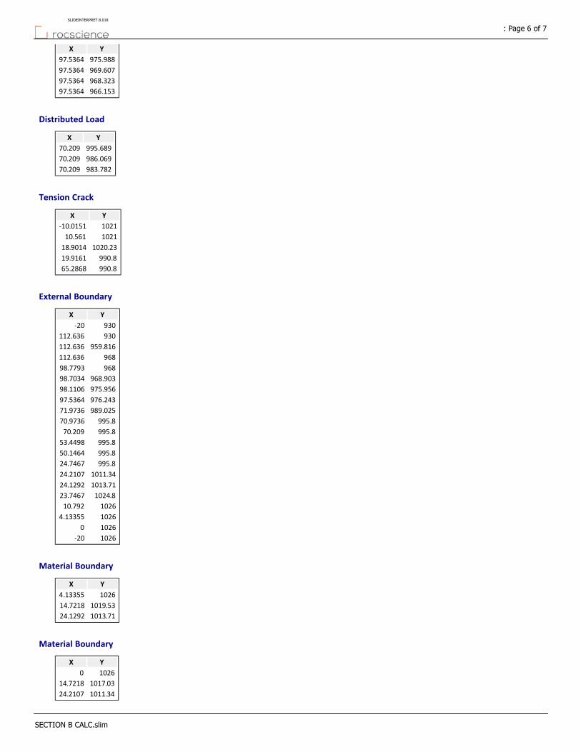
YX
975.98897.5364
969.60797.5364
968.32397.5364
966.15397.5364
Distributed Load
YX
995.68970.209
986.06970.209
983.78270.209
Tension Crack
YX
1021‐10.0151
102110.561
1020.2318.9014
990.819.9161
990.865.2868
External Boundary
YX
930‐20
930112.636
959.816112.636
968112.636
96898.7793
968.90398.7034
975.95698.1106
976.24397.5364
989.02571.9736
995.870.9736
995.870.209
995.853.4498
995.850.1464
995.824.7467
1011.3424.2107
1013.7124.1292
1024.823.7467
102610.792
10264.13355
10260
1026‐20
Material Boundary
YX
10264.13355
1019.5314.7218
1013.7124.1292
Material Boundary
YX
10260
1017.0314.7218
1011.3424.2107
: Page 6 of 7SLIDEINTERPRET 8.018
SECTION B CALC.slim
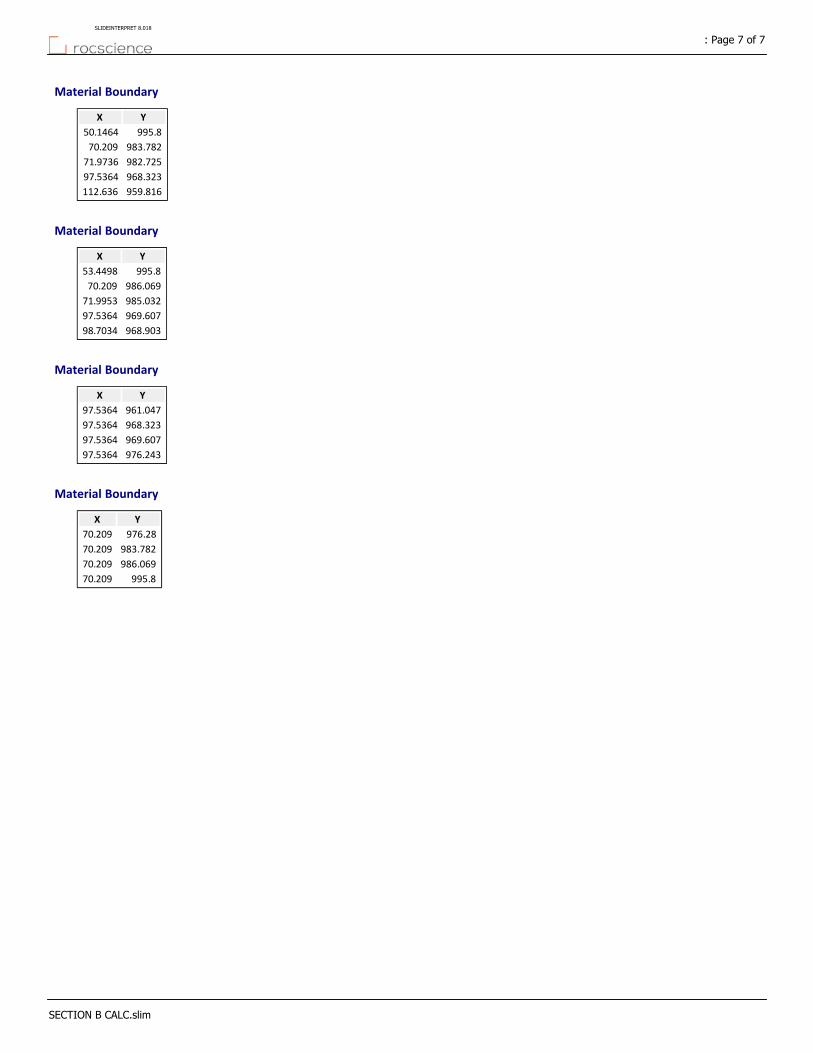
Material Boundary
YX
995.850.1464
983.78270.209
982.72571.9736
968.32397.5364
959.816112.636
Material Boundary
YX
995.853.4498
986.06970.209
985.03271.9953
969.60797.5364
968.90398.7034
Material Boundary
YX
961.04797.5364
968.32397.5364
969.60797.5364
976.24397.5364
Material Boundary
YX
976.2870.209
983.78270.209
986.06970.209
995.870.209
: Page 7 of 7SLIDEINTERPRET 8.018
SECTION B CALC.slim
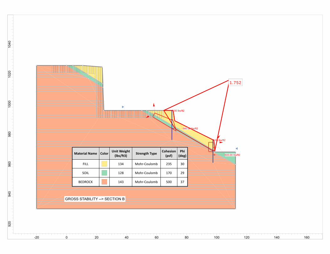
1.7521.752
0.00 lbs/ft2
600.00 lbs/ft2
0.00 lbs/ft2
540.00 lbs/ft2
1.7521.752
Material Name ColorUnit Weight(lbs/ 3)
Strength TypeCohesion(psf)
Phi(deg)
FILL 134 Mohr‐Coulomb 235 30
SOIL 128 Mohr‐Coulomb 170 29
BEDROCK 143 Mohr‐Coulomb 500 37
GROSS STABILITY --> SECTION B
1040
1020
1000
980
960
940
920
-20 0 20 40 60 80 100 120 140 160
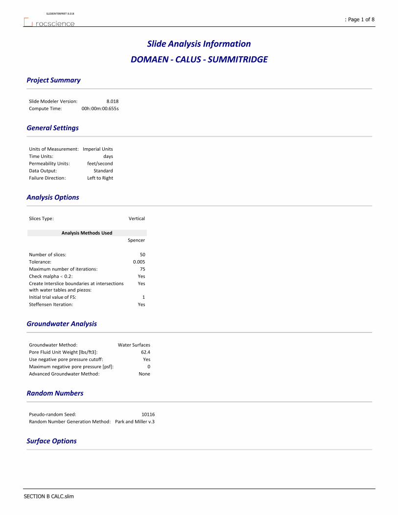
Slide Analysis Information
DOMAEN ‐ CALUS ‐ SUMMITRIDGE
Project Summary
8.018Slide Modeler Version:
00h:00m:00.655sCompute Time:
General Settings
Imperial UnitsUnits of Measurement:
daysTime Units:
feet/secondPermeability Units:
StandardData Output:
Left to RightFailure Direction:
Analysis Options
VerticalSlices Type:
Analysis Methods Used
Spencer
50Number of slices:
0.005Tolerance:
75Maximum number of iterations:
YesCheck malpha < 0.2:YesCreate Interslice boundaries at intersections
with water tables and piezos:
1Initial trial value of FS:
YesSteffensen Iteration:
Groundwater Analysis
Water SurfacesGroundwater Method:
62.4Pore Fluid Unit Weight [lbs/ft3]:
YesUse negative pore pressure cutoff:
0Maximum negative pore pressure [psf]:
NoneAdvanced Groundwater Method:
Random Numbers
10116Pseudo‐random Seed:
Park and Miller v.3Random Number Generation Method:
Surface Options
: Page 1 of 8SLIDEINTERPRET 8.018
SECTION B CALC.slim
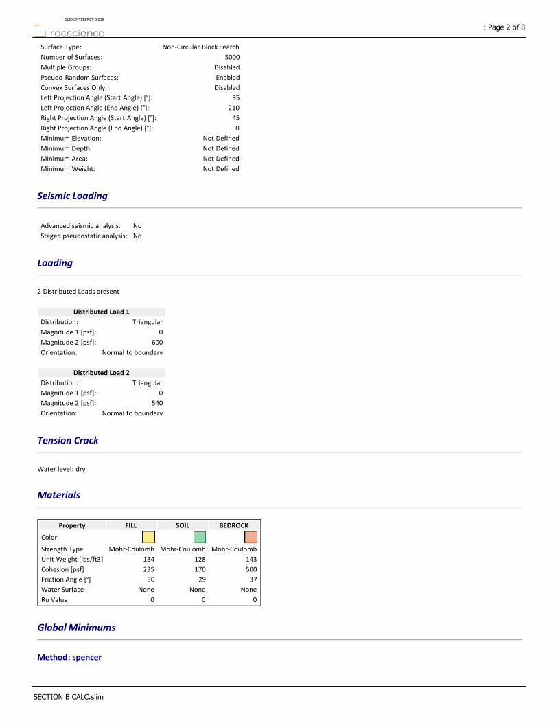
Non‐Circular Block SearchSurface Type:
5000Number of Surfaces:
DisabledMultiple Groups:
EnabledPseudo‐Random Surfaces:
DisabledConvex Surfaces Only:
95Left Projection Angle (Start Angle) [°]:
210Left Projection Angle (End Angle) [°]:
45Right Projection Angle (Start Angle) [°]:
0Right Projection Angle (End Angle) [°]:
Not DefinedMinimum Elevation:
Not DefinedMinimum Depth:
Not DefinedMinimum Area:
Not DefinedMinimum Weight:
Seismic Loading
NoAdvanced seismic analysis:
NoStaged pseudostatic analysis:
Loading
2 Distributed Loads present
Distributed Load 1
TriangularDistribution:
0Magnitude 1 [psf]:
600Magnitude 2 [psf]:
Normal to boundaryOrientation:
Distributed Load 2
TriangularDistribution:
0Magnitude 1 [psf]:
540Magnitude 2 [psf]:
Normal to boundaryOrientation:
Tension Crack
Water level: dry
Materials
BEDROCKSOILFILLProperty
Color
Mohr‐CoulombMohr‐CoulombMohr‐CoulombStrength Type
143128134Unit Weight [lbs/ft3]
500170235Cohesion [psf]
372930Friction Angle [°]
NoneNoneNoneWater Surface
000Ru Value
Global Minimums
Method: spencer
: Page 2 of 8SLIDEINTERPRET 8.018
SECTION B CALC.slim
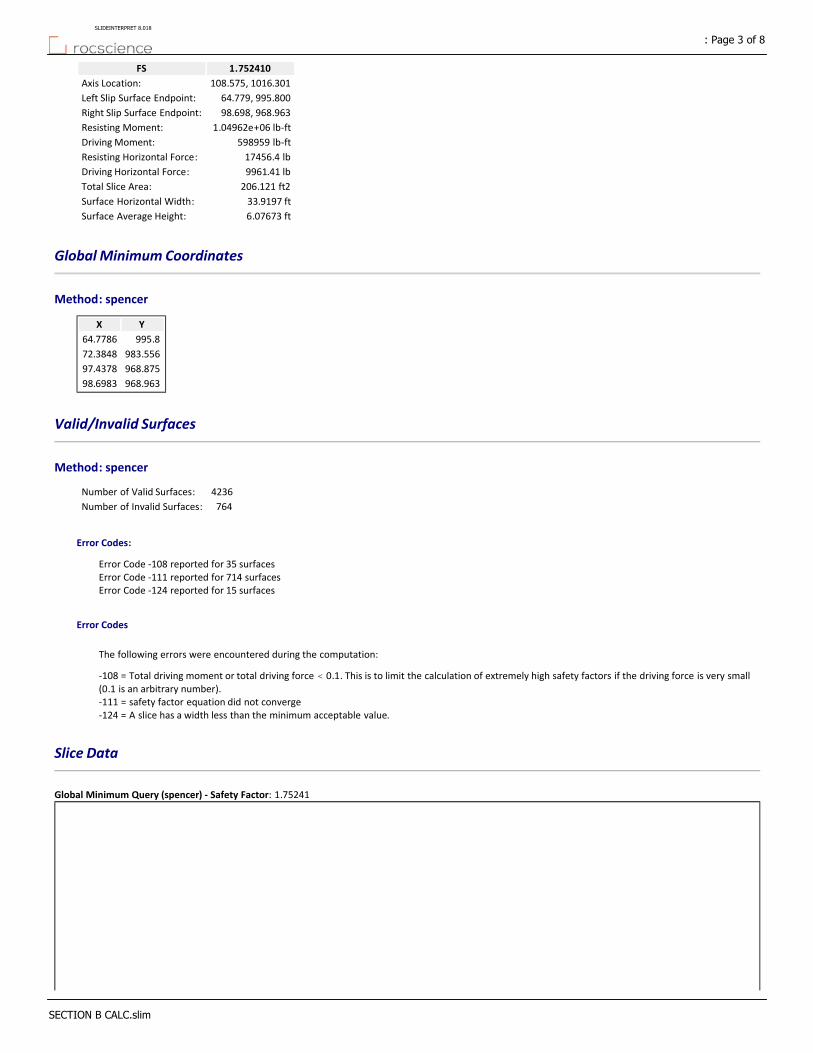
1.752410FS
108.575, 1016.301Axis Location:
64.779, 995.800Left Slip Surface Endpoint:
98.698, 968.963Right Slip Surface Endpoint:
1.04962e+06 lb‐ftResisting Moment:
598959 lb‐ftDriving Moment:
17456.4 lbResisting Horizontal Force:
9961.41 lbDriving Horizontal Force:
206.121 ft2Total Slice Area:
33.9197 ftSurface Horizontal Width:
6.07673 ftSurface Average Height:
Global Minimum Coordinates
Method: spencer
YX
995.864.7786
983.55672.3848
968.87597.4378
968.96398.6983
Valid/Invalid Surfaces
Method: spencer
4236Number of Valid Surfaces:
764Number of Invalid Surfaces:
Error Codes:
Error Code ‐108 reported for 35 surfacesError Code ‐111 reported for 714 surfacesError Code ‐124 reported for 15 surfaces
Error Codes
The following errors were encountered during the computation:
‐108 = Total driving moment or total driving force < 0.1. This is to limit the calculation of extremely high safety factors if the driving force is very small (0.1 is an arbitrary number).‐111 = safety factor equation did not converge‐124 = A slice has a width less than the minimum acceptable value.
Slice Data
Global Minimum Query (spencer) ‐ Safety Factor: 1.75241
: Page 3 of 8SLIDEINTERPRET 8.018
SECTION B CALC.slim
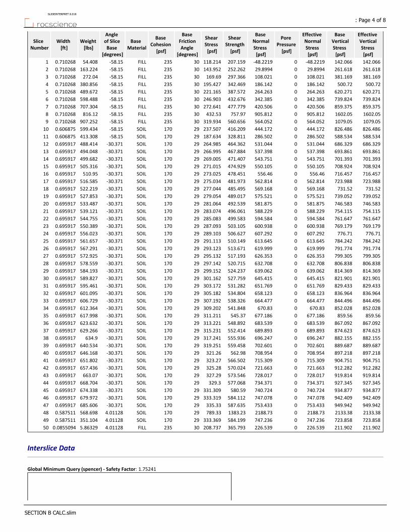
Effective Vertical Stress [psf]
Base Vertical Stress [psf]
Effective Normal Stress [psf]
Pore Pressure [psf]
Base Normal Stress [psf]
Shear Strength [psf]
Shear Stress [psf]
Base Friction Angle
[degrees]
Base Cohesion
[psf]
Base Material
Angle of Slice Base
[degrees]
Weight [lbs]
Width [ft]
Slice Number
142.066142.066‐48.22190‐48.2219207.159118.21430235FILL‐58.1554.4080.7102681
261.618261.61829.8994029.8994252.262143.95230235FILL‐58.15163.2240.7102682
381.169381.169108.0210108.021297.366169.6930235FILL‐58.15272.040.7102683
500.72500.72186.1420186.142342.469195.42730235FILL‐58.15380.8560.7102684
620.271620.271264.2630264.263387.572221.16530235FILL‐58.15489.6720.7102685
739.824739.824342.3850342.385432.676246.90330235FILL‐58.15598.4880.7102686
859.375859.375420.5060420.506477.779272.64130235FILL‐58.15707.3040.7102687
1602.051602.05905.8120905.812757.97432.5330235FILL‐58.15816.120.7102688
1079.051079.05564.0520564.052560.656319.93430235FILL‐58.15907.2520.7102689
826.486826.486444.1720444.172416.209237.50729170SOIL‐58.15599.4340.60687510
588.534588.534286.5020286.502328.811187.63429170SOIL‐58.15413.3080.60687511
686.329686.329531.0440531.044464.362264.98529170SOIL‐30.371488.4140.69591712
693.861693.861537.3980537.398467.884266.99529170SOIL‐30.371494.0480.69591713
701.393701.393543.7510543.751471.407269.00529170SOIL‐30.371499.6820.69591714
708.924708.924550.1050550.105474.929271.01529170SOIL‐30.371505.3160.69591715
716.457716.457556.460556.46478.451273.02529170SOIL‐30.371510.950.69591716
723.988723.988562.8140562.814481.973275.03429170SOIL‐30.371516.5850.69591717
731.52731.52569.1680569.168485.495277.04429170SOIL‐30.371522.2190.69591718
739.052739.052575.5210575.521489.017279.05429170SOIL‐30.371527.8530.69591719
746.583746.583581.8750581.875492.539281.06429170SOIL‐30.371533.4870.69591720
754.115754.115588.2290588.229496.061283.07429170SOIL‐30.371539.1210.69591721
761.647761.647594.5840594.584499.583285.08329170SOIL‐30.371544.7550.69591722
769.179769.179600.9380600.938503.105287.09329170SOIL‐30.371550.3890.69591723
776.71776.71607.2920607.292506.627289.10329170SOIL‐30.371556.0230.69591724
784.242784.242613.6450613.645510.149291.11329170SOIL‐30.371561.6570.69591725
791.774791.774619.9990619.999513.671293.12329170SOIL‐30.371567.2910.69591726
799.305799.305626.3530626.353517.193295.13229170SOIL‐30.371572.9250.69591727
806.838806.838632.7080632.708520.715297.14229170SOIL‐30.371578.5590.69591728
814.369814.369639.0620639.062524.237299.15229170SOIL‐30.371584.1930.69591729
821.901821.901645.4150645.415527.759301.16229170SOIL‐30.371589.8270.69591730
829.433829.433651.7690651.769531.282303.17229170SOIL‐30.371595.4610.69591731
836.964836.964658.1230658.123534.804305.18229170SOIL‐30.371601.0950.69591732
844.496844.496664.4770664.477538.326307.19229170SOIL‐30.371606.7290.69591733
852.028852.028670.830670.83541.848309.20229170SOIL‐30.371612.3640.69591734
859.56859.56677.1860677.186545.37311.21129170SOIL‐30.371617.9980.69591735
867.092867.092683.5390683.539548.892313.22129170SOIL‐30.371623.6320.69591736
874.623874.623689.8930689.893552.414315.23129170SOIL‐30.371629.2660.69591737
882.155882.155696.2470696.247555.936317.24129170SOIL‐30.371634.90.69591738
889.687889.687702.6010702.601559.458319.25129170SOIL‐30.371640.5340.69591739
897.218897.218708.9540708.954562.98321.2629170SOIL‐30.371646.1680.69591740
904.751904.751715.3090715.309566.502323.2729170SOIL‐30.371651.8020.69591741
912.282912.282721.6630721.663570.024325.2829170SOIL‐30.371657.4360.69591742
919.814919.814728.0170728.017573.546327.2929170SOIL‐30.371663.070.69591743
927.345927.345734.3710734.371577.068329.329170SOIL‐30.371668.7040.69591744
934.877934.877740.7240740.724580.59331.30929170SOIL‐30.371674.3380.69591745
942.409942.409747.0780747.078584.112333.31929170SOIL‐30.371679.9720.69591746
949.942949.942753.4330753.433587.635335.3329170SOIL‐30.371685.6060.69591747
2133.382133.382188.7302188.731383.23789.3329170SOIL4.01128568.6980.58751148
723.858723.858747.2360747.236584.199333.36929170SOIL4.01128351.1040.58751149
211.902211.902226.5390226.539365.793208.73730235FILL4.011285.863290.085509450
Interslice Data
Global Minimum Query (spencer) ‐ Safety Factor: 1.75241
: Page 4 of 8SLIDEINTERPRET 8.018
SECTION B CALC.slim
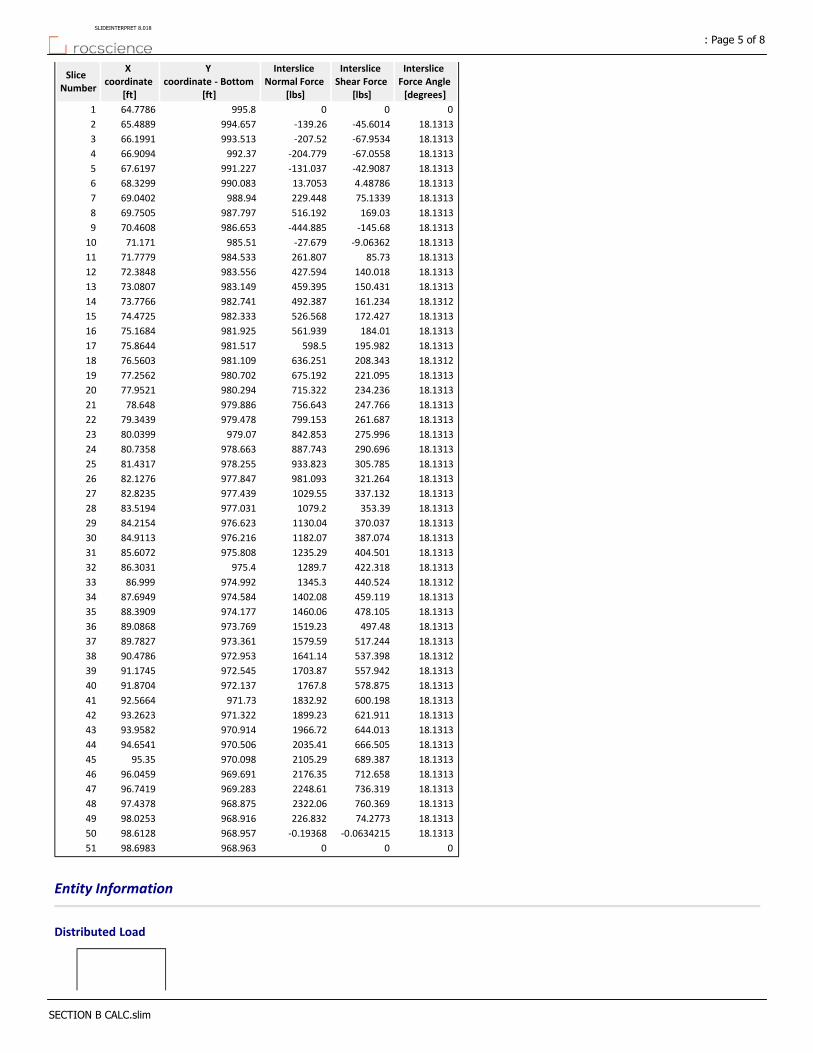
Interslice Force Angle [degrees]
Interslice Shear Force
[lbs]
Interslice Normal Force
[lbs]
Y coordinate ‐ Bottom
[ft]
X coordinate
[ft]
Slice Number
000995.864.77861
18.1313‐45.6014‐139.26994.65765.48892
18.1313‐67.9534‐207.52993.51366.19913
18.1313‐67.0558‐204.779992.3766.90944
18.1313‐42.9087‐131.037991.22767.61975
18.13134.4878613.7053990.08368.32996
18.131375.1339229.448988.9469.04027
18.1313169.03516.192987.79769.75058
18.1313‐145.68‐444.885986.65370.46089
18.1313‐9.06362‐27.679985.5171.17110
18.131385.73261.807984.53371.777911
18.1313140.018427.594983.55672.384812
18.1313150.431459.395983.14973.080713
18.1312161.234492.387982.74173.776614
18.1313172.427526.568982.33374.472515
18.1313184.01561.939981.92575.168416
18.1313195.982598.5981.51775.864417
18.1312208.343636.251981.10976.560318
18.1313221.095675.192980.70277.256219
18.1313234.236715.322980.29477.952120
18.1313247.766756.643979.88678.64821
18.1313261.687799.153979.47879.343922
18.1313275.996842.853979.0780.039923
18.1313290.696887.743978.66380.735824
18.1313305.785933.823978.25581.431725
18.1313321.264981.093977.84782.127626
18.1313337.1321029.55977.43982.823527
18.1313353.391079.2977.03183.519428
18.1313370.0371130.04976.62384.215429
18.1313387.0741182.07976.21684.911330
18.1313404.5011235.29975.80885.607231
18.1313422.3181289.7975.486.303132
18.1312440.5241345.3974.99286.99933
18.1313459.1191402.08974.58487.694934
18.1313478.1051460.06974.17788.390935
18.1313497.481519.23973.76989.086836
18.1313517.2441579.59973.36189.782737
18.1312537.3981641.14972.95390.478638
18.1313557.9421703.87972.54591.174539
18.1313578.8751767.8972.13791.870440
18.1313600.1981832.92971.7392.566441
18.1313621.9111899.23971.32293.262342
18.1313644.0131966.72970.91493.958243
18.1313666.5052035.41970.50694.654144
18.1313689.3872105.29970.09895.3545
18.1313712.6582176.35969.69196.045946
18.1313736.3192248.61969.28396.741947
18.1313760.3692322.06968.87597.437848
18.131374.2773226.832968.91698.025349
18.1313‐0.0634215‐0.19368968.95798.612850
000968.96398.698351
Entity Information
Distributed Load
: Page 5 of 8SLIDEINTERPRET 8.018
SECTION B CALC.slim

YX
975.98897.5364
969.60797.5364
968.32397.5364
966.15397.5364
Distributed Load
YX
995.68970.209
986.06970.209
983.78270.209
Tension Crack
YX
1021‐10.0151
102110.561
1020.2318.9014
990.819.9161
990.865.2868
Block Search Window
YX
989.16271.048
994.18758.57
991.43757.4309
982.14972.9975
Block Search Window
YX
974.65194.598
968.32394.598
968.32397.5364
974.48497.5364
External Boundary
: Page 6 of 8SLIDEINTERPRET 8.018
SECTION B CALC.slim
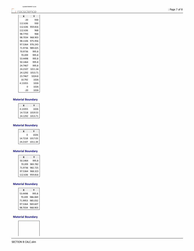
YX
930‐20
930112.636
959.816112.636
968112.636
96898.7793
968.90398.7034
975.95698.1106
976.24397.5364
989.02571.9736
995.870.9736
995.870.209
995.853.4498
995.850.1464
995.824.7467
1011.3424.2107
1013.7124.1292
1024.823.7467
102610.792
10264.13355
10260
1026‐20
Material Boundary
YX
10264.13355
1019.5314.7218
1013.7124.1292
Material Boundary
YX
10260
1017.0314.7218
1011.3424.2107
Material Boundary
YX
995.850.1464
983.78270.209
982.72571.9736
968.32397.5364
959.816112.636
Material Boundary
YX
995.853.4498
986.06970.209
985.03271.9953
969.60797.5364
968.90398.7034
Material Boundary
: Page 7 of 8SLIDEINTERPRET 8.018
SECTION B CALC.slim
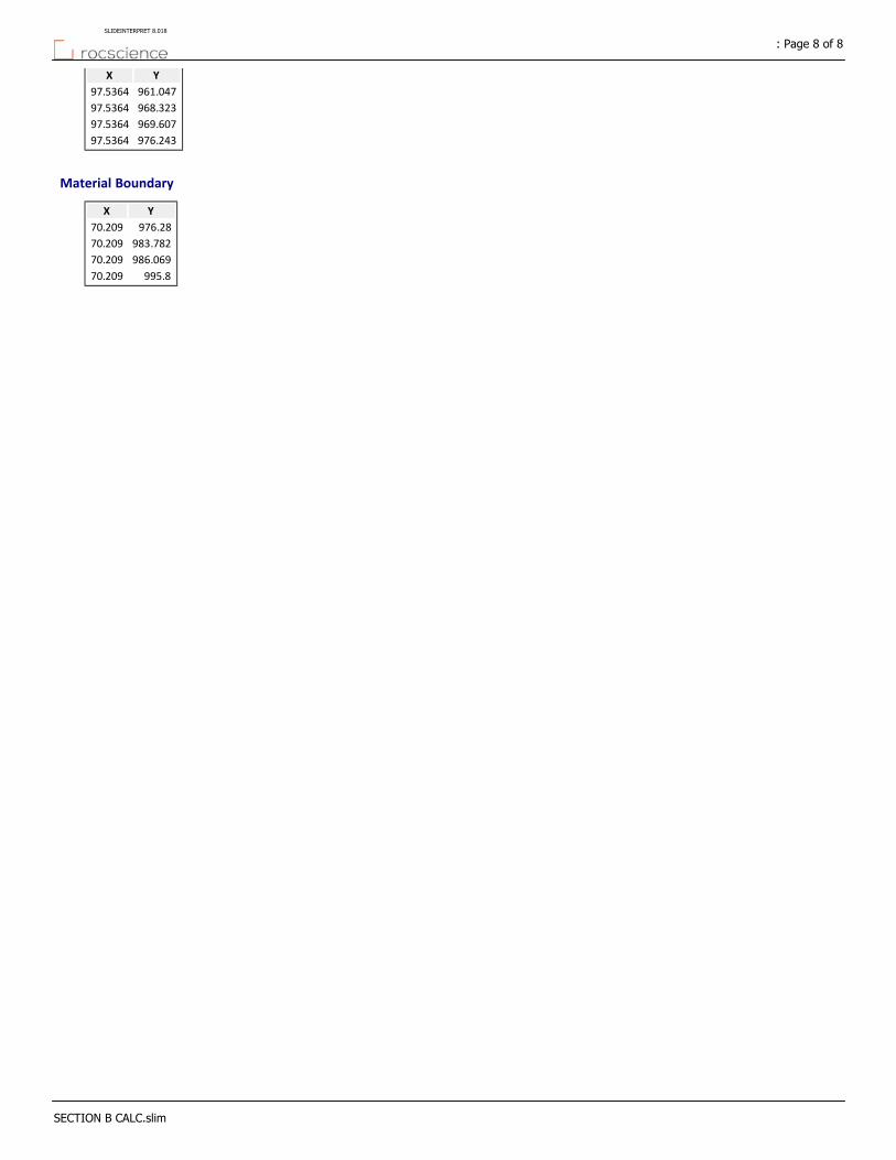
YX
961.04797.5364
968.32397.5364
969.60797.5364
976.24397.5364
Material Boundary
YX
976.2870.209
983.78270.209
986.06970.209
995.870.209
: Page 8 of 8SLIDEINTERPRET 8.018
SECTION B CALC.slim
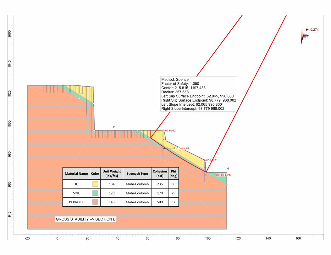
0.00 lbs/ft2
800.00 lbs/ft2
0.00 lbs/ft2
720.00 lbs/ft2
Material Name ColorUnit Weight(lbs/ 3)
Strength TypeCohesion(psf)
Phi(deg)
FILL 134 Mohr‐Coulomb 235 30
SOIL 128 Mohr‐Coulomb 170 29
BEDROCK 143 Mohr‐Coulomb 500 37
GROSS STABILITY --> SECTION B
Method: SpencerFactor of Safety: 1.050Center: 215.815, 1197.433Radius: 257.558Left Slip Surface Endpoint: 62.065, 990.800Right Slip Surface Endpoint: 98.779, 968.002Left Slope Intercept: 62.065 995.800Right Slope Intercept: 98.779 968.002
0.274
1060
1040
1020
1000
980
960
940
-20 0 20 40 60 80 100 120 140 160

Slide Analysis Information
DOMAEN ‐ CALUS ‐ SUMMITRIDGE
Project Summary
8.018Slide Modeler Version:
00h:00m:01.277sCompute Time:
General Settings
Imperial UnitsUnits of Measurement:
daysTime Units:
feet/secondPermeability Units:
StandardData Output:
Left to RightFailure Direction:
Analysis Options
VerticalSlices Type:
Analysis Methods Used
Spencer
50Number of slices:
0.005Tolerance:
75Maximum number of iterations:
YesCheck malpha < 0.2:YesCreate Interslice boundaries at intersections
with water tables and piezos:
1Initial trial value of FS:
YesSteffensen Iteration:
Groundwater Analysis
Water SurfacesGroundwater Method:
62.4Pore Fluid Unit Weight [lbs/ft3]:
YesUse negative pore pressure cutoff:
0Maximum negative pore pressure [psf]:
NoneAdvanced Groundwater Method:
Random Numbers
10116Pseudo‐random Seed:
Park and Miller v.3Random Number Generation Method:
Surface Options
: Page 1 of 7SLIDEINTERPRET 8.018
SECTION B CALC.slim

CircularSurface Type:
Auto Refine SearchSearch Method:
20Divisions along slope:
10Circles per division:
10Number of iterations:
50%Divisions to use in next iteration:
DisabledComposite Surfaces:
Not DefinedMinimum Elevation:
Not DefinedMinimum Depth:
Not DefinedMinimum Area:
Not DefinedMinimum Weight:
Seismic Loading
NoAdvanced seismic analysis:
NoStaged pseudostatic analysis:
0.274Seismic Load Coefficient (Horizontal):
Loading
2 Distributed Loads present
Distributed Load 1
TriangularDistribution:
0Magnitude 1 [psf]:
800Magnitude 2 [psf]:
Normal to boundaryOrientation:
Distributed Load 2
TriangularDistribution:
0Magnitude 1 [psf]:
720Magnitude 2 [psf]:
Normal to boundaryOrientation:
Tension Crack
Water level: dry
Materials
BEDROCKSOILFILLProperty
Color
Mohr‐CoulombMohr‐CoulombMohr‐CoulombStrength Type
143128134Unit Weight [lbs/ft3]
500170235Cohesion [psf]
372930Friction Angle [°]
NoneNoneNoneWater Surface
000Ru Value
Global Minimums
Method: spencer
: Page 2 of 7SLIDEINTERPRET 8.018
SECTION B CALC.slim

1.049760FS
215.815, 1197.433Center:
257.558Radius:
62.065, 990.800Left Slip Surface Endpoint:
98.779, 968.002Right Slip Surface Endpoint:
62.065 995.800Left Slope Intercept:
98.779 968.002Right Slope Intercept:
5.80534e+06 lb‐ftResisting Moment:
5.53016e+06 lb‐ftDriving Moment:
19194.6 lbResisting Horizontal Force:
18284.8 lbDriving Horizontal Force:
261.051 ft2Total Slice Area:
36.7137 ftSurface Horizontal Width:
7.11046 ftSurface Average Height:
Valid/Invalid Surfaces
Method: spencer
8835Number of Valid Surfaces:
0Number of Invalid Surfaces:
Slice Data
Global Minimum Query (spencer) ‐ Safety Factor: 1.04976
: Page 3 of 7SLIDEINTERPRET 8.018
SECTION B CALC.slim
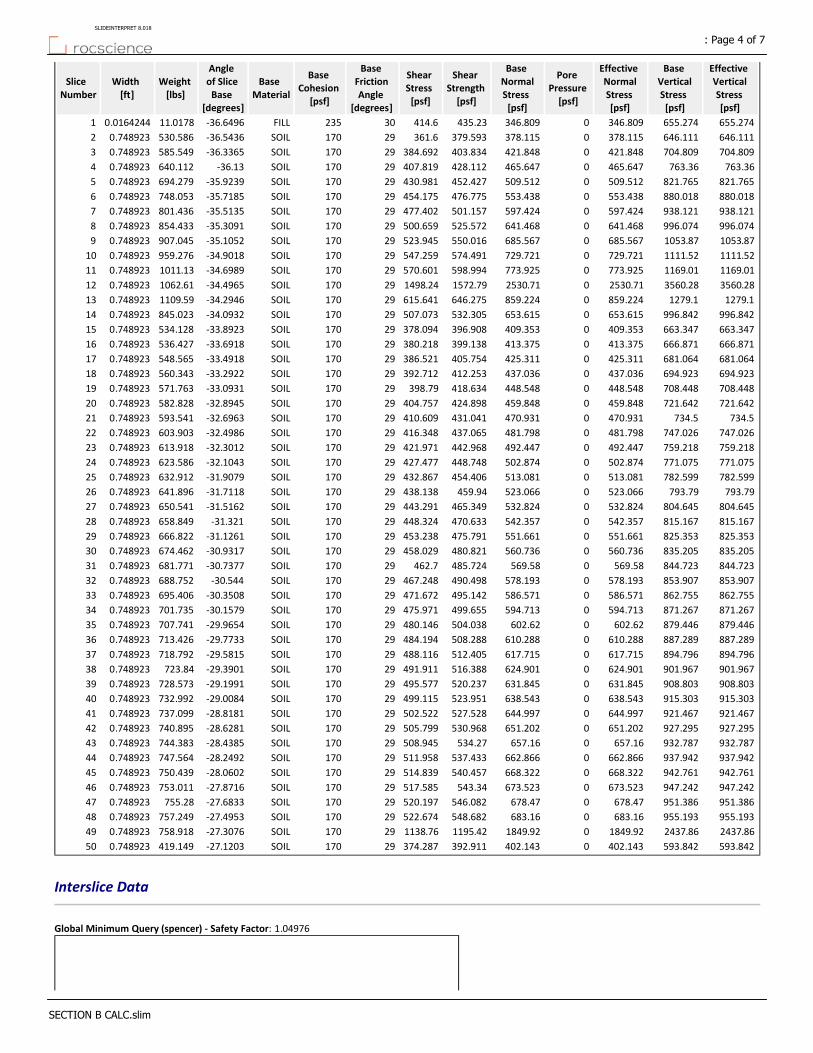
Effective Vertical Stress [psf]
Base Vertical Stress [psf]
Effective Normal Stress [psf]
Pore Pressure [psf]
Base Normal Stress [psf]
Shear Strength [psf]
Shear Stress [psf]
Base Friction Angle
[degrees]
Base Cohesion
[psf]
Base Material
Angle of Slice Base
[degrees]
Weight [lbs]
Width [ft]
Slice Number
655.274655.274346.8090346.809435.23414.630235FILL‐36.649611.01780.01642441
646.111646.111378.1150378.115379.593361.629170SOIL‐36.5436530.5860.7489232
704.809704.809421.8480421.848403.834384.69229170SOIL‐36.3365585.5490.7489233
763.36763.36465.6470465.647428.112407.81929170SOIL‐36.13640.1120.7489234
821.765821.765509.5120509.512452.427430.98129170SOIL‐35.9239694.2790.7489235
880.018880.018553.4380553.438476.775454.17529170SOIL‐35.7185748.0530.7489236
938.121938.121597.4240597.424501.157477.40229170SOIL‐35.5135801.4360.7489237
996.074996.074641.4680641.468525.572500.65929170SOIL‐35.3091854.4330.7489238
1053.871053.87685.5670685.567550.016523.94529170SOIL‐35.1052907.0450.7489239
1111.521111.52729.7210729.721574.491547.25929170SOIL‐34.9018959.2760.74892310
1169.011169.01773.9250773.925598.994570.60129170SOIL‐34.69891011.130.74892311
3560.283560.282530.7102530.711572.791498.2429170SOIL‐34.49651062.610.74892312
1279.11279.1859.2240859.224646.275615.64129170SOIL‐34.29461109.590.74892313
996.842996.842653.6150653.615532.305507.07329170SOIL‐34.0932845.0230.74892314
663.347663.347409.3530409.353396.908378.09429170SOIL‐33.8923534.1280.74892315
666.871666.871413.3750413.375399.138380.21829170SOIL‐33.6918536.4270.74892316
681.064681.064425.3110425.311405.754386.52129170SOIL‐33.4918548.5650.74892317
694.923694.923437.0360437.036412.253392.71229170SOIL‐33.2922560.3430.74892318
708.448708.448448.5480448.548418.634398.7929170SOIL‐33.0931571.7630.74892319
721.642721.642459.8480459.848424.898404.75729170SOIL‐32.8945582.8280.74892320
734.5734.5470.9310470.931431.041410.60929170SOIL‐32.6963593.5410.74892321
747.026747.026481.7980481.798437.065416.34829170SOIL‐32.4986603.9030.74892322
759.218759.218492.4470492.447442.968421.97129170SOIL‐32.3012613.9180.74892323
771.075771.075502.8740502.874448.748427.47729170SOIL‐32.1043623.5860.74892324
782.599782.599513.0810513.081454.406432.86729170SOIL‐31.9079632.9120.74892325
793.79793.79523.0660523.066459.94438.13829170SOIL‐31.7118641.8960.74892326
804.645804.645532.8240532.824465.349443.29129170SOIL‐31.5162650.5410.74892327
815.167815.167542.3570542.357470.633448.32429170SOIL‐31.321658.8490.74892328
825.353825.353551.6610551.661475.791453.23829170SOIL‐31.1261666.8220.74892329
835.205835.205560.7360560.736480.821458.02929170SOIL‐30.9317674.4620.74892330
844.723844.723569.580569.58485.724462.729170SOIL‐30.7377681.7710.74892331
853.907853.907578.1930578.193490.498467.24829170SOIL‐30.544688.7520.74892332
862.755862.755586.5710586.571495.142471.67229170SOIL‐30.3508695.4060.74892333
871.267871.267594.7130594.713499.655475.97129170SOIL‐30.1579701.7350.74892334
879.446879.446602.620602.62504.038480.14629170SOIL‐29.9654707.7410.74892335
887.289887.289610.2880610.288508.288484.19429170SOIL‐29.7733713.4260.74892336
894.796894.796617.7150617.715512.405488.11629170SOIL‐29.5815718.7920.74892337
901.967901.967624.9010624.901516.388491.91129170SOIL‐29.3901723.840.74892338
908.803908.803631.8450631.845520.237495.57729170SOIL‐29.1991728.5730.74892339
915.303915.303638.5430638.543523.951499.11529170SOIL‐29.0084732.9920.74892340
921.467921.467644.9970644.997527.528502.52229170SOIL‐28.8181737.0990.74892341
927.295927.295651.2020651.202530.968505.79929170SOIL‐28.6281740.8950.74892342
932.787932.787657.160657.16534.27508.94529170SOIL‐28.4385744.3830.74892343
937.942937.942662.8660662.866537.433511.95829170SOIL‐28.2492747.5640.74892344
942.761942.761668.3220668.322540.457514.83929170SOIL‐28.0602750.4390.74892345
947.242947.242673.5230673.523543.34517.58529170SOIL‐27.8716753.0110.74892346
951.386951.386678.470678.47546.082520.19729170SOIL‐27.6833755.280.74892347
955.193955.193683.160683.16548.682522.67429170SOIL‐27.4953757.2490.74892348
2437.862437.861849.9201849.921195.421138.7629170SOIL‐27.3076758.9180.74892349
593.842593.842402.1430402.143392.911374.28729170SOIL‐27.1203419.1490.74892350
Interslice Data
Global Minimum Query (spencer) ‐ Safety Factor: 1.04976
: Page 4 of 7SLIDEINTERPRET 8.018
SECTION B CALC.slim

Interslice Force Angle [degrees]
Interslice Shear Force
[lbs]
Interslice Normal Force
[lbs]
Y coordinate ‐ Bottom
[ft]
X coordinate
[ft]
Slice Number
000990.862.06551
26.78350.2165540.429011990.78862.08192
26.783642.475884.1477990.23362.83083
26.783594.9458188.095989.68263.57974
26.7836157.4311.821989.13564.32875
26.7835229.612454.879988.59365.07766
26.7836311.36616.828988.05465.82657
26.7835402.422797.229987.5266.57548
26.7836502.579995.646986.98967.32449
26.7835611.6111211.65986.46368.073310
26.7835729.3051444.81985.9468.822211
26.7836855.4441694.7985.42269.571112
26.7836‐657.25‐1302.06984.90770.3213
26.7835‐515.613‐1021.47984.39671.06914
26.7836‐423.696‐839.373983.88971.817915
26.7836‐389.181‐770.997983.38672.566816
26.7835‐354.923‐703.13982.88773.315717
26.7836‐319.177‐632.313982.39174.064718
26.7835‐282.04‐558.743981.89974.813619
26.7836‐243.612‐482.614981.41175.562520
26.7836‐203.988‐404.115980.92776.311421
26.7836‐163.262‐323.434980.44677.060422
26.7835‐121.526‐240.753979.96977.809323
26.7836‐78.8719‐156.251979.49678.558224
26.7836‐35.3876‐70.1055979.02679.307125
26.78368.8394117.5115978.55980.05626
26.783553.7238106.431978.09780.80527
26.783699.1817196.486977.63781.553928
26.7835145.131287.516977.18282.302829
26.7836191.492379.36976.7383.051730
26.7836238.185471.862976.28183.800731
26.7836285.133564.87975.83584.549632
26.7836332.261658.234975.39385.298533
26.7836379.495751.808974.95586.047434
26.7836426.763845.449974.5286.796435
26.7836473.994939.017974.08887.545336
26.7837521.1181032.37973.6688.294237
26.7836568.071125.39973.23489.043138
26.7835614.7811217.93972.81389.79239
26.7835661.1891309.87972.39490.54140
26.7835707.2311401.08971.97991.289941
26.7836752.8441491.44971.56792.038842
26.7835797.971580.84971.15892.787743
26.7836842.551669.15970.75293.536744
26.7835886.5261756.28970.3594.285645
26.7836929.8451842.09969.95195.034546
26.7836972.4521926.5969.55595.783447
26.78361014.32009.4969.16296.532448
26.78351055.322090.67968.77297.281349
26.7836‐18.7315‐37.1085968.38598.030250
000968.00298.779151
Entity Information
Distributed Load
: Page 5 of 7SLIDEINTERPRET 8.018
SECTION B CALC.slim
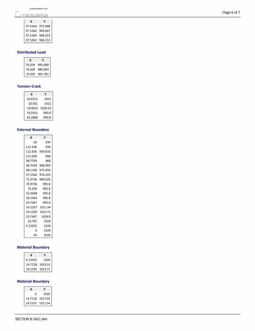
YX
975.98897.5364
969.60797.5364
968.32397.5364
966.15397.5364
Distributed Load
YX
995.68970.209
986.06970.209
983.78270.209
Tension Crack
YX
1021‐10.0151
102110.561
1020.2318.9014
990.819.9161
990.865.2868
External Boundary
YX
930‐20
930112.636
959.816112.636
968112.636
96898.7793
968.90398.7034
975.95698.1106
976.24397.5364
989.02571.9736
995.870.9736
995.870.209
995.853.4498
995.850.1464
995.824.7467
1011.3424.2107
1013.7124.1292
1024.823.7467
102610.792
10264.13355
10260
1026‐20
Material Boundary
YX
10264.13355
1019.5314.7218
1013.7124.1292
Material Boundary
YX
10260
1017.0314.7218
1011.3424.2107
: Page 6 of 7SLIDEINTERPRET 8.018
SECTION B CALC.slim
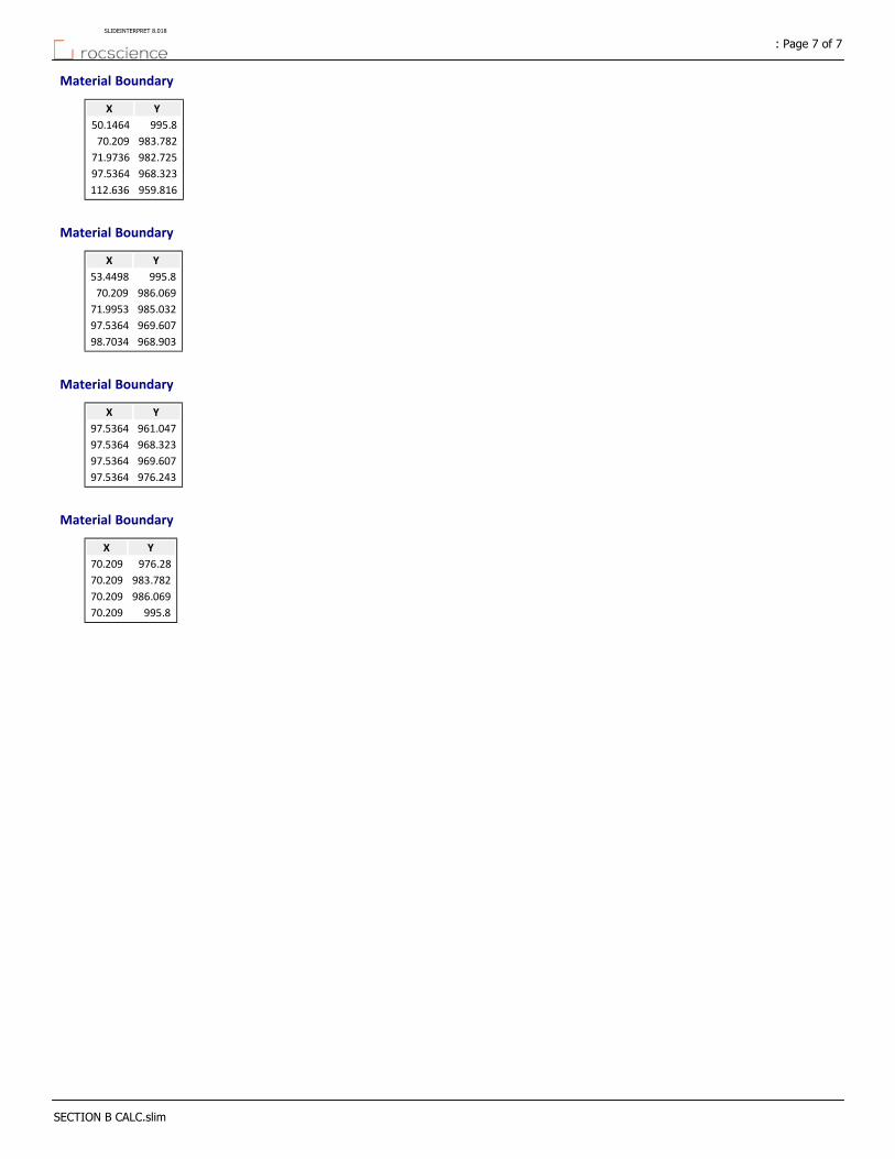
Material Boundary
YX
995.850.1464
983.78270.209
982.72571.9736
968.32397.5364
959.816112.636
Material Boundary
YX
995.853.4498
986.06970.209
985.03271.9953
969.60797.5364
968.90398.7034
Material Boundary
YX
961.04797.5364
968.32397.5364
969.60797.5364
976.24397.5364
Material Boundary
YX
976.2870.209
983.78270.209
986.06970.209
995.870.209
: Page 7 of 7SLIDEINTERPRET 8.018
SECTION B CALC.slim
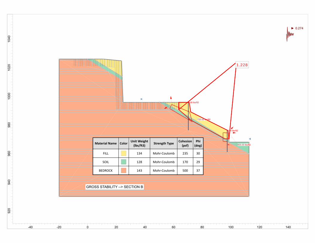
1.2281.228
0.00 lbs/ft2
800.00 lbs/ft2
0.00 lbs/ft2
720.00 lbs/ft2
1.2281.228
Material Name ColorUnit Weight(lbs/ 3)
Strength TypeCohesion(psf)
Phi(deg)
FILL 134 Mohr‐Coulomb 235 30
SOIL 128 Mohr‐Coulomb 170 29
BEDROCK 143 Mohr‐Coulomb 500 37
GROSS STABILITY --> SECTION B
0.274
1040
1020
1000
980
960
940
920
-40 -20 0 20 40 60 80 100 120 140
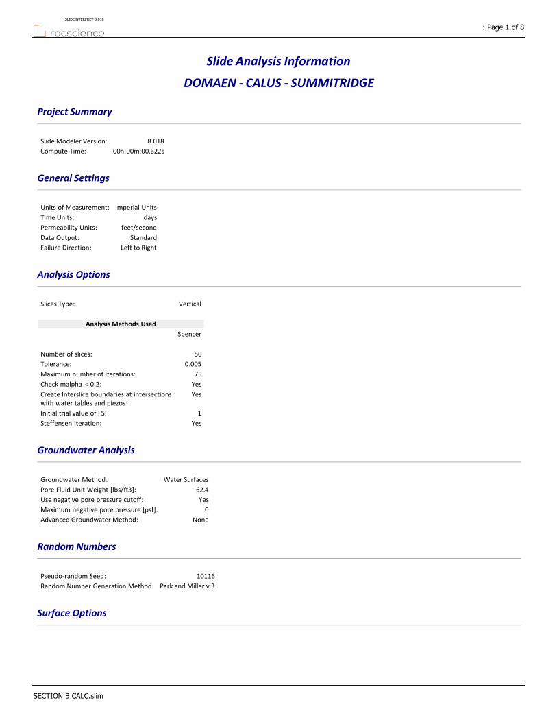
Slide Analysis Information
DOMAEN ‐ CALUS ‐ SUMMITRIDGE
Project Summary
8.018Slide Modeler Version:
00h:00m:00.622sCompute Time:
General Settings
Imperial UnitsUnits of Measurement:
daysTime Units:
feet/secondPermeability Units:
StandardData Output:
Left to RightFailure Direction:
Analysis Options
VerticalSlices Type:
Analysis Methods Used
Spencer
50Number of slices:
0.005Tolerance:
75Maximum number of iterations:
YesCheck malpha < 0.2:YesCreate Interslice boundaries at intersections
with water tables and piezos:
1Initial trial value of FS:
YesSteffensen Iteration:
Groundwater Analysis
Water SurfacesGroundwater Method:
62.4Pore Fluid Unit Weight [lbs/ft3]:
YesUse negative pore pressure cutoff:
0Maximum negative pore pressure [psf]:
NoneAdvanced Groundwater Method:
Random Numbers
10116Pseudo‐random Seed:
Park and Miller v.3Random Number Generation Method:
Surface Options
: Page 1 of 8SLIDEINTERPRET 8.018
SECTION B CALC.slim
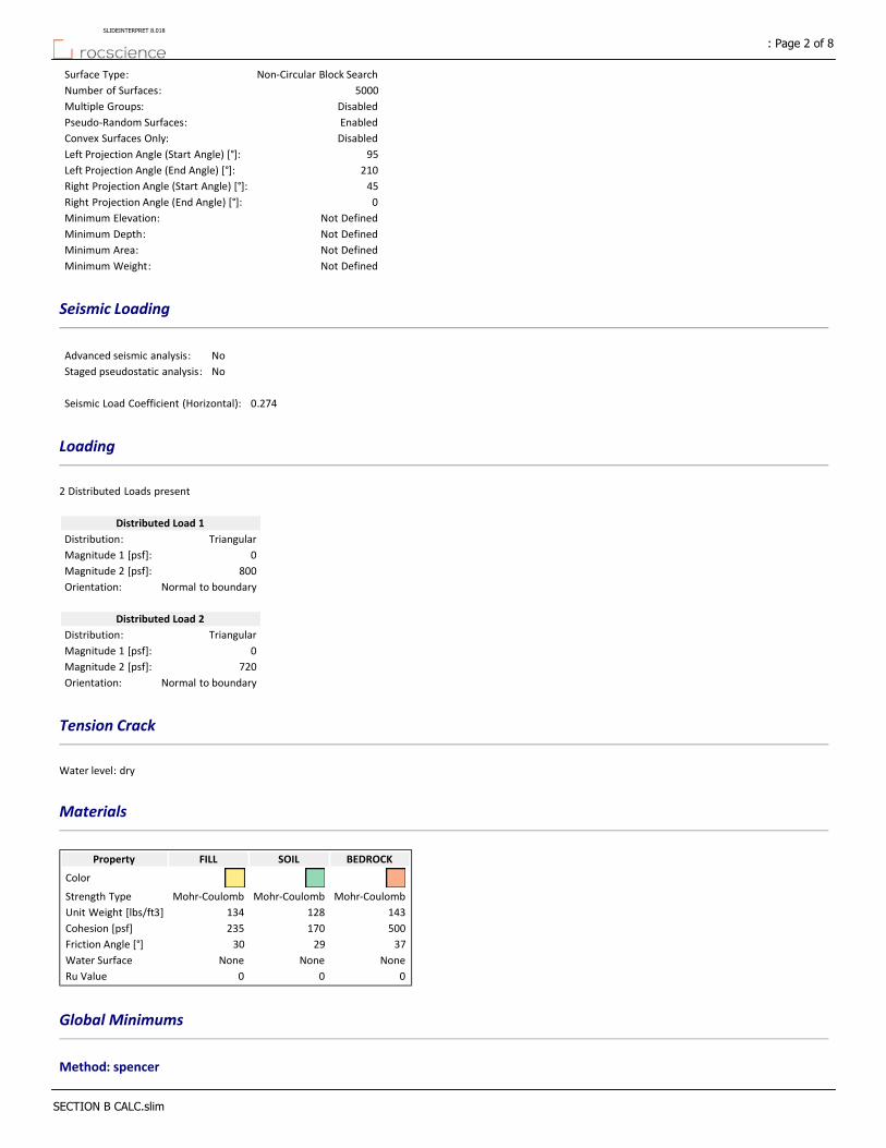
Non‐Circular Block SearchSurface Type:
5000Number of Surfaces:
DisabledMultiple Groups:
EnabledPseudo‐Random Surfaces:
DisabledConvex Surfaces Only:
95Left Projection Angle (Start Angle) [°]:
210Left Projection Angle (End Angle) [°]:
45Right Projection Angle (Start Angle) [°]:
0Right Projection Angle (End Angle) [°]:
Not DefinedMinimum Elevation:
Not DefinedMinimum Depth:
Not DefinedMinimum Area:
Not DefinedMinimum Weight:
Seismic Loading
NoAdvanced seismic analysis:
NoStaged pseudostatic analysis:
0.274Seismic Load Coefficient (Horizontal):
Loading
2 Distributed Loads present
Distributed Load 1
TriangularDistribution:
0Magnitude 1 [psf]:
800Magnitude 2 [psf]:
Normal to boundaryOrientation:
Distributed Load 2
TriangularDistribution:
0Magnitude 1 [psf]:
720Magnitude 2 [psf]:
Normal to boundaryOrientation:
Tension Crack
Water level: dry
Materials
BEDROCKSOILFILLProperty
Color
Mohr‐CoulombMohr‐CoulombMohr‐CoulombStrength Type
143128134Unit Weight [lbs/ft3]
500170235Cohesion [psf]
372930Friction Angle [°]
NoneNoneNoneWater Surface
000Ru Value
Global Minimums
Method: spencer
: Page 2 of 8SLIDEINTERPRET 8.018
SECTION B CALC.slim
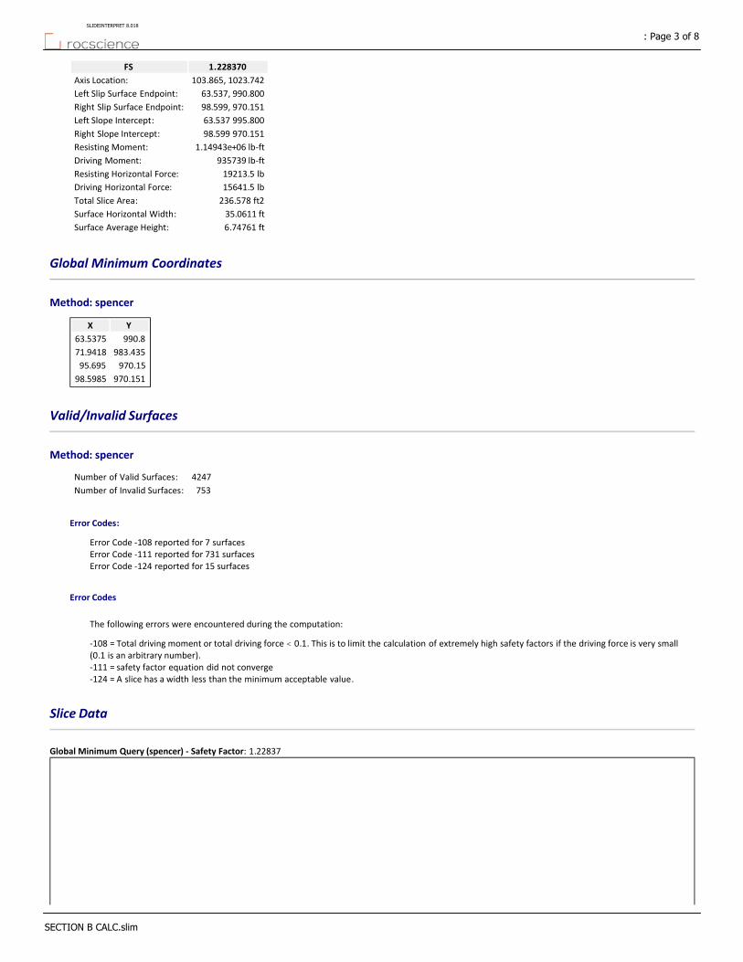
1.228370FS
103.865, 1023.742Axis Location:
63.537, 990.800Left Slip Surface Endpoint:
98.599, 970.151Right Slip Surface Endpoint:
63.537 995.800Left Slope Intercept:
98.599 970.151Right Slope Intercept:
1.14943e+06 lb‐ftResisting Moment:
935739 lb‐ftDriving Moment:
19213.5 lbResisting Horizontal Force:
15641.5 lbDriving Horizontal Force:
236.578 ft2Total Slice Area:
35.0611 ftSurface Horizontal Width:
6.74761 ftSurface Average Height:
Global Minimum Coordinates
Method: spencer
YX
990.863.5375
983.43571.9418
970.1595.695
970.15198.5985
Valid/Invalid Surfaces
Method: spencer
4247Number of Valid Surfaces:
753Number of Invalid Surfaces:
Error Codes:
Error Code ‐108 reported for 7 surfacesError Code ‐111 reported for 731 surfacesError Code ‐124 reported for 15 surfaces
Error Codes
The following errors were encountered during the computation:
‐108 = Total driving moment or total driving force < 0.1. This is to limit the calculation of extremely high safety factors if the driving force is very small (0.1 is an arbitrary number).‐111 = safety factor equation did not converge‐124 = A slice has a width less than the minimum acceptable value.
Slice Data
Global Minimum Query (spencer) ‐ Safety Factor: 1.22837
: Page 3 of 8SLIDEINTERPRET 8.018
SECTION B CALC.slim
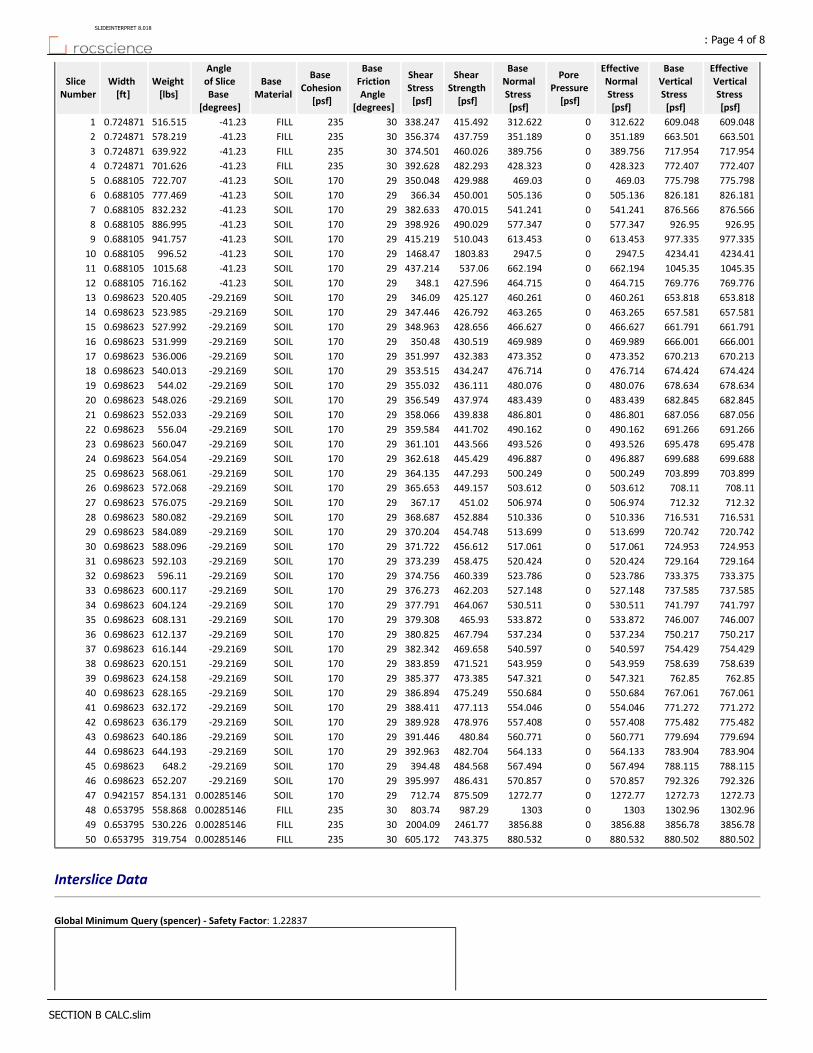
Effective Vertical Stress [psf]
Base Vertical Stress [psf]
Effective Normal Stress [psf]
Pore Pressure [psf]
Base Normal Stress [psf]
Shear Strength [psf]
Shear Stress [psf]
Base Friction Angle
[degrees]
Base Cohesion
[psf]
Base Material
Angle of Slice Base
[degrees]
Weight [lbs]
Width [ft]
Slice Number
609.048609.048312.6220312.622415.492338.24730235FILL‐41.23516.5150.7248711
663.501663.501351.1890351.189437.759356.37430235FILL‐41.23578.2190.7248712
717.954717.954389.7560389.756460.026374.50130235FILL‐41.23639.9220.7248713
772.407772.407428.3230428.323482.293392.62830235FILL‐41.23701.6260.7248714
775.798775.798469.030469.03429.988350.04829170SOIL‐41.23722.7070.6881055
826.181826.181505.1360505.136450.001366.3429170SOIL‐41.23777.4690.6881056
876.566876.566541.2410541.241470.015382.63329170SOIL‐41.23832.2320.6881057
926.95926.95577.3470577.347490.029398.92629170SOIL‐41.23886.9950.6881058
977.335977.335613.4530613.453510.043415.21929170SOIL‐41.23941.7570.6881059
4234.414234.412947.502947.51803.831468.4729170SOIL‐41.23996.520.68810510
1045.351045.35662.1940662.194537.06437.21429170SOIL‐41.231015.680.68810511
769.776769.776464.7150464.715427.596348.129170SOIL‐41.23716.1620.68810512
653.818653.818460.2610460.261425.127346.0929170SOIL‐29.2169520.4050.69862313
657.581657.581463.2650463.265426.792347.44629170SOIL‐29.2169523.9850.69862314
661.791661.791466.6270466.627428.656348.96329170SOIL‐29.2169527.9920.69862315
666.001666.001469.9890469.989430.519350.4829170SOIL‐29.2169531.9990.69862316
670.213670.213473.3520473.352432.383351.99729170SOIL‐29.2169536.0060.69862317
674.424674.424476.7140476.714434.247353.51529170SOIL‐29.2169540.0130.69862318
678.634678.634480.0760480.076436.111355.03229170SOIL‐29.2169544.020.69862319
682.845682.845483.4390483.439437.974356.54929170SOIL‐29.2169548.0260.69862320
687.056687.056486.8010486.801439.838358.06629170SOIL‐29.2169552.0330.69862321
691.266691.266490.1620490.162441.702359.58429170SOIL‐29.2169556.040.69862322
695.478695.478493.5260493.526443.566361.10129170SOIL‐29.2169560.0470.69862323
699.688699.688496.8870496.887445.429362.61829170SOIL‐29.2169564.0540.69862324
703.899703.899500.2490500.249447.293364.13529170SOIL‐29.2169568.0610.69862325
708.11708.11503.6120503.612449.157365.65329170SOIL‐29.2169572.0680.69862326
712.32712.32506.9740506.974451.02367.1729170SOIL‐29.2169576.0750.69862327
716.531716.531510.3360510.336452.884368.68729170SOIL‐29.2169580.0820.69862328
720.742720.742513.6990513.699454.748370.20429170SOIL‐29.2169584.0890.69862329
724.953724.953517.0610517.061456.612371.72229170SOIL‐29.2169588.0960.69862330
729.164729.164520.4240520.424458.475373.23929170SOIL‐29.2169592.1030.69862331
733.375733.375523.7860523.786460.339374.75629170SOIL‐29.2169596.110.69862332
737.585737.585527.1480527.148462.203376.27329170SOIL‐29.2169600.1170.69862333
741.797741.797530.5110530.511464.067377.79129170SOIL‐29.2169604.1240.69862334
746.007746.007533.8720533.872465.93379.30829170SOIL‐29.2169608.1310.69862335
750.217750.217537.2340537.234467.794380.82529170SOIL‐29.2169612.1370.69862336
754.429754.429540.5970540.597469.658382.34229170SOIL‐29.2169616.1440.69862337
758.639758.639543.9590543.959471.521383.85929170SOIL‐29.2169620.1510.69862338
762.85762.85547.3210547.321473.385385.37729170SOIL‐29.2169624.1580.69862339
767.061767.061550.6840550.684475.249386.89429170SOIL‐29.2169628.1650.69862340
771.272771.272554.0460554.046477.113388.41129170SOIL‐29.2169632.1720.69862341
775.482775.482557.4080557.408478.976389.92829170SOIL‐29.2169636.1790.69862342
779.694779.694560.7710560.771480.84391.44629170SOIL‐29.2169640.1860.69862343
783.904783.904564.1330564.133482.704392.96329170SOIL‐29.2169644.1930.69862344
788.115788.115567.4940567.494484.568394.4829170SOIL‐29.2169648.20.69862345
792.326792.326570.8570570.857486.431395.99729170SOIL‐29.2169652.2070.69862346
1272.731272.731272.7701272.77875.509712.7429170SOIL0.00285146854.1310.94215747
1302.961302.96130301303987.29803.7430235FILL0.00285146558.8680.65379548
3856.783856.783856.8803856.882461.772004.0930235FILL0.00285146530.2260.65379549
880.502880.502880.5320880.532743.375605.17230235FILL0.00285146319.7540.65379550
Interslice Data
Global Minimum Query (spencer) ‐ Safety Factor: 1.22837
: Page 4 of 8SLIDEINTERPRET 8.018
SECTION B CALC.slim
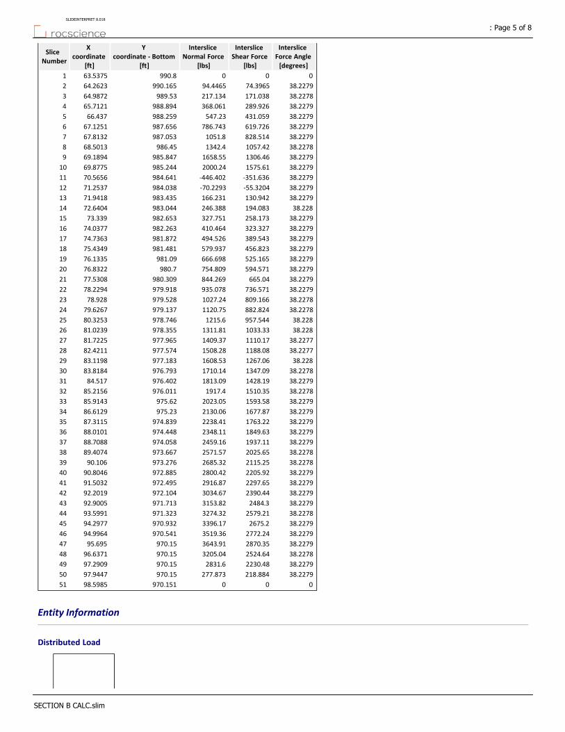
Interslice Force Angle [degrees]
Interslice Shear Force
[lbs]
Interslice Normal Force
[lbs]
Y coordinate ‐ Bottom
[ft]
X coordinate
[ft]
Slice Number
000990.863.53751
38.227974.396594.4465990.16564.26232
38.2278171.038217.134989.5364.98723
38.2279289.926368.061988.89465.71214
38.2279431.059547.23988.25966.4375
38.2279619.726786.743987.65667.12516
38.2279828.5141051.8987.05367.81327
38.22781057.421342.4986.4568.50138
38.22791306.461658.55985.84769.18949
38.22791575.612000.24985.24469.877510
38.2279‐351.636‐446.402984.64170.565611
38.2279‐55.3204‐70.2293984.03871.253712
38.2279130.942166.231983.43571.941813
38.228194.083246.388983.04472.640414
38.2279258.173327.751982.65373.33915
38.2279323.327410.464982.26374.037716
38.2279389.543494.526981.87274.736317
38.2279456.823579.937981.48175.434918
38.2279525.165666.698981.0976.133519
38.2279594.571754.809980.776.832220
38.2279665.04844.269980.30977.530821
38.2279736.571935.078979.91878.229422
38.2278809.1661027.24979.52878.92823
38.2278882.8241120.75979.13779.626724
38.228957.5441215.6978.74680.325325
38.2281033.331311.81978.35581.023926
38.22771110.171409.37977.96581.722527
38.22771188.081508.28977.57482.421128
38.2281267.061608.53977.18383.119829
38.22781347.091710.14976.79383.818430
38.22791428.191813.09976.40284.51731
38.22781510.351917.4976.01185.215632
38.22791593.582023.05975.6285.914333
38.22791677.872130.06975.2386.612934
38.22791763.222238.41974.83987.311535
38.22791849.632348.11974.44888.010136
38.22791937.112459.16974.05888.708837
38.22782025.652571.57973.66789.407438
38.22782115.252685.32973.27690.10639
38.22792205.922800.42972.88590.804640
38.22792297.652916.87972.49591.503241
38.22792390.443034.67972.10492.201942
38.22792484.33153.82971.71392.900543
38.22782579.213274.32971.32393.599144
38.22792675.23396.17970.93294.297745
38.22792772.243519.36970.54194.996446
38.22792870.353643.91970.1595.69547
38.22782524.643205.04970.1596.637148
38.22792230.482831.6970.1597.290949
38.2279218.884277.873970.1597.944750
000970.15198.598551
Entity Information
Distributed Load
: Page 5 of 8SLIDEINTERPRET 8.018
SECTION B CALC.slim
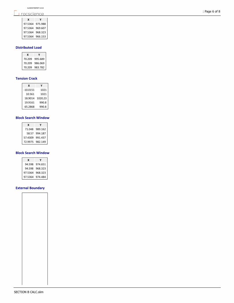
YX
975.98897.5364
969.60797.5364
968.32397.5364
966.15397.5364
Distributed Load
YX
995.68970.209
986.06970.209
983.78270.209
Tension Crack
YX
1021‐10.0151
102110.561
1020.2318.9014
990.819.9161
990.865.2868
Block Search Window
YX
989.16271.048
994.18758.57
991.43757.4309
982.14972.9975
Block Search Window
YX
974.65194.598
968.32394.598
968.32397.5364
974.48497.5364
External Boundary
: Page 6 of 8SLIDEINTERPRET 8.018
SECTION B CALC.slim
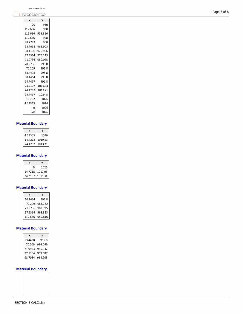
YX
930‐20
930112.636
959.816112.636
968112.636
96898.7793
968.90398.7034
975.95698.1106
976.24397.5364
989.02571.9736
995.870.9736
995.870.209
995.853.4498
995.850.1464
995.824.7467
1011.3424.2107
1013.7124.1292
1024.823.7467
102610.792
10264.13355
10260
1026‐20
Material Boundary
YX
10264.13355
1019.5314.7218
1013.7124.1292
Material Boundary
YX
10260
1017.0314.7218
1011.3424.2107
Material Boundary
YX
995.850.1464
983.78270.209
982.72571.9736
968.32397.5364
959.816112.636
Material Boundary
YX
995.853.4498
986.06970.209
985.03271.9953
969.60797.5364
968.90398.7034
Material Boundary
: Page 7 of 8SLIDEINTERPRET 8.018
SECTION B CALC.slim
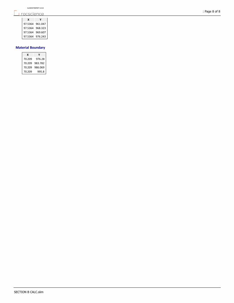
YX
961.04797.5364
968.32397.5364
969.60797.5364
976.24397.5364
Material Boundary
YX
976.2870.209
983.78270.209
986.06970.209
995.870.209
: Page 8 of 8SLIDEINTERPRET 8.018
SECTION B CALC.slim
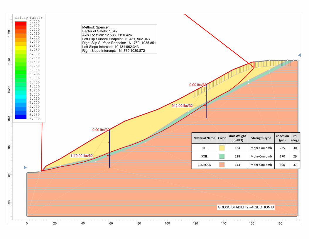
0.00 lbs/ft2
1110.00 lbs/ft2
0.00 lbs/ft2
912.00 lbs/ft2
Material Name ColorUnit Weight(lbs/ 3)
Strength TypeCohesion(psf)
Phi(deg)
FILL 134 Mohr‐Coulomb 235 30
SOIL 128 Mohr‐Coulomb 170 29
BEDROCK 143 Mohr‐Coulomb 500 37
GROSS STABILITY --> SECTION D
Method: SpencerFactor of Safety: 1.642Axis Location: 12.588, 1150.426Left Slip Surface Endpoint: 10.431, 962.343Right Slip Surface Endpoint: 161.760, 1035.851Left Slope Intercept: 10.431 962.343Right Slope Intercept: 161.760 1039.872
Safety Factor0.0000.2500.5000.7501.0001.2501.5001.7502.0002.2502.5002.7503.0003.2503.5003.7504.0004.2504.5004.7505.0005.2505.5005.7506.000+
1060
1040
1020
1000
980
960
940
0 20 40 60 80 100 120 140 160 180

Slide Analysis Information
DOMAEN ‐ CALUS ‐ SUMMITRIDGE
Project Summary
8.018Slide Modeler Version:
00h:00m:08.424sCompute Time:
General Settings
Imperial UnitsUnits of Measurement:
daysTime Units:
feet/secondPermeability Units:
StandardData Output:
Right to LeftFailure Direction:
Analysis Options
VerticalSlices Type:
Analysis Methods Used
Spencer
50Number of slices:
0.005Tolerance:
75Maximum number of iterations:
YesCheck malpha < 0.2:YesCreate Interslice boundaries at intersections
with water tables and piezos:
1Initial trial value of FS:
YesSteffensen Iteration:
Groundwater Analysis
Water SurfacesGroundwater Method:
62.4Pore Fluid Unit Weight [lbs/ft3]:
YesUse negative pore pressure cutoff:
0Maximum negative pore pressure [psf]:
NoneAdvanced Groundwater Method:
Random Numbers
10116Pseudo‐random Seed:
Park and Miller v.3Random Number Generation Method:
Surface Options
: Page 1 of 8SLIDEINTERPRET 8.018
SECTION D CALC.slim
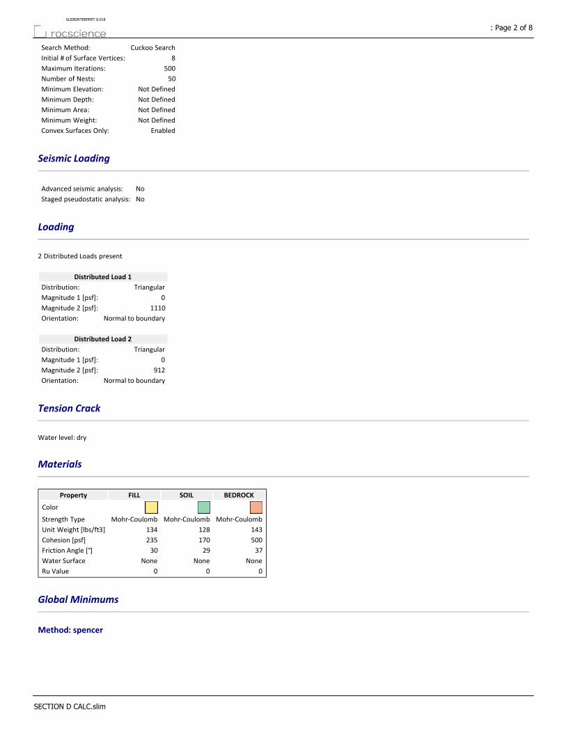
Cuckoo SearchSearch Method:
8Initial # of Surface Vertices:
500Maximum Iterations:
50Number of Nests:
Not DefinedMinimum Elevation:
Not DefinedMinimum Depth:
Not DefinedMinimum Area:
Not DefinedMinimum Weight:
EnabledConvex Surfaces Only:
Seismic Loading
NoAdvanced seismic analysis:
NoStaged pseudostatic analysis:
Loading
2 Distributed Loads present
Distributed Load 1
TriangularDistribution:
0Magnitude 1 [psf]:
1110Magnitude 2 [psf]:
Normal to boundaryOrientation:
Distributed Load 2
TriangularDistribution:
0Magnitude 1 [psf]:
912Magnitude 2 [psf]:
Normal to boundaryOrientation:
Tension Crack
Water level: dry
Materials
BEDROCKSOILFILLProperty
Color
Mohr‐CoulombMohr‐CoulombMohr‐CoulombStrength Type
143128134Unit Weight [lbs/ft3]
500170235Cohesion [psf]
372930Friction Angle [°]
NoneNoneNoneWater Surface
000Ru Value
Global Minimums
Method: spencer
: Page 2 of 8SLIDEINTERPRET 8.018
SECTION D CALC.slim
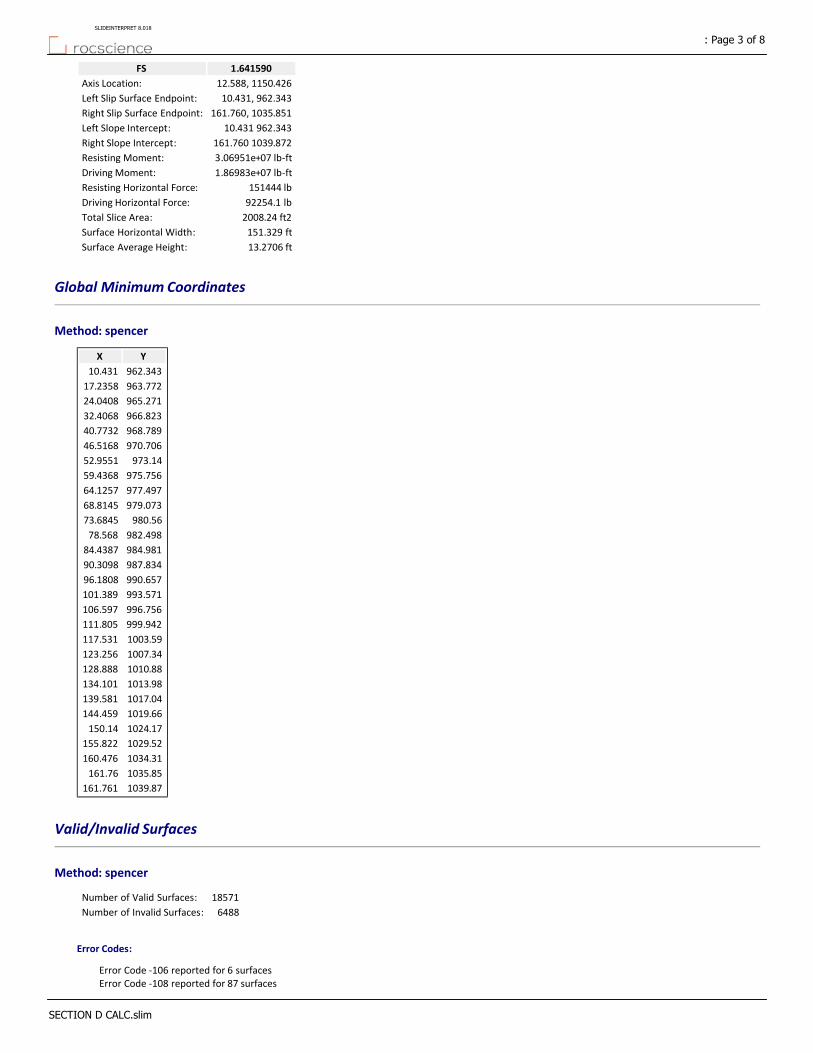
1.641590FS
12.588, 1150.426Axis Location:
10.431, 962.343Left Slip Surface Endpoint:
161.760, 1035.851Right Slip Surface Endpoint:
10.431 962.343Left Slope Intercept:
161.760 1039.872Right Slope Intercept:
3.06951e+07 lb‐ftResisting Moment:
1.86983e+07 lb‐ftDriving Moment:
151444 lbResisting Horizontal Force:
92254.1 lbDriving Horizontal Force:
2008.24 ft2Total Slice Area:
151.329 ftSurface Horizontal Width:
13.2706 ftSurface Average Height:
Global Minimum Coordinates
Method: spencer
YX
962.34310.431
963.77217.2358
965.27124.0408
966.82332.4068
968.78940.7732
970.70646.5168
973.1452.9551
975.75659.4368
977.49764.1257
979.07368.8145
980.5673.6845
982.49878.568
984.98184.4387
987.83490.3098
990.65796.1808
993.571101.389
996.756106.597
999.942111.805
1003.59117.531
1007.34123.256
1010.88128.888
1013.98134.101
1017.04139.581
1019.66144.459
1024.17150.14
1029.52155.822
1034.31160.476
1035.85161.76
1039.87161.761
Valid/Invalid Surfaces
Method: spencer
18571Number of Valid Surfaces:
6488Number of Invalid Surfaces:
Error Codes:
Error Code ‐106 reported for 6 surfacesError Code ‐108 reported for 87 surfaces
: Page 3 of 8SLIDEINTERPRET 8.018
SECTION D CALC.slim
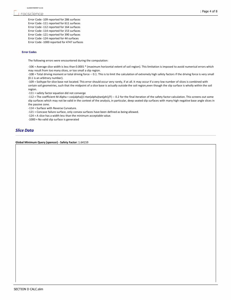
Error Code ‐109 reported for 286 surfacesError Code ‐111 reported for 611 surfacesError Code ‐112 reported for 164 surfacesError Code ‐114 reported for 153 surfacesError Code ‐121 reported for 390 surfacesError Code ‐124 reported for 44 surfacesError Code ‐1000 reported for 4747 surfaces
Error Codes
The following errors were encountered during the computation:
‐106 = Average slice width is less than 0.0001 * (maximum horizontal extent of soil region). This limitation is imposed to avoid numerical errors which may result from too many slices, or too small a slip region.‐108 = Total driving moment or total driving force < 0.1. This is to limit the calculation of extremely high safety factors if the driving force is very small (0.1 is an arbitrary number).‐109 = Soiltype for slice base not located. This error should occur very rarely, if at all. It may occur if a very low number of slices is combined with certain soil geometries, such that the midpoint of a slice base is actually outside the soil region,even though the slip surface is wholly within the soil region.‐111 = safety factor equation did not converge‐112 = The coefficient M‐Alpha = cos(alpha)(1+tan(alpha)tan(phi)/F) < 0.2 for the final iteration of the safety factor calculation. This screens out some slip surfaces which may not be valid in the context of the analysis, in particular, deep seated slip surfaces with many high negative base angle slices in the passive zone.‐114 = Surface with Reverse Curvature.‐121 = Concave failure surface, only convex surfaces have been defined as being allowed.‐124 = A slice has a width less than the minimum acceptable value.‐1000 = No valid slip surface is generated
Slice Data
Global Minimum Query (spencer) ‐ Safety Factor: 1.64159
: Page 4 of 8SLIDEINTERPRET 8.018
SECTION D CALC.slim

Effective Vertical Stress [psf]
Base Vertical Stress [psf]
Effective Normal Stress [psf]
Pore Pressure [psf]
Base Normal Stress [psf]
Shear Strength [psf]
Shear Stress [psf]
Base Friction Angle
[degrees]
Base Cohesion
[psf]
Base Material
Angle of Slice Base
[degrees]
Weight [lbs]
Width [ft]
Slice Number
213.151213.151178.7380178.738269.076163.91229170SOIL11.8571549.9093.402381
521.03521.03466.2340466.234428.438260.9929170SOIL11.85711546.583.402382
733.729733.729661.6660661.666536.767326.9829170SOIL12.42874490.616.804983
1010.561010.56932.9280932.928687.13418.57629170SOIL10.50723809.014.183034
1255.771255.771163.6901163.69815.042496.49529170SOIL10.50724774.964.183035
1456.841456.841327.1701327.17905.664551.69929170SOIL13.22645685.584.183166
1669.451669.451524.1501524.151014.85618.21329170SOIL13.22646540.574.183167
1762.21762.21552.6801552.681030.67627.84629170SOIL18.45394933.082.87188
1866.371866.371646.3101646.311082.56659.4629170SOIL18.45395231.892.87189
1933.721933.721680.101680.11101.29670.8729170SOIL20.7096179.823.2191910
2015.082015.081752.2501752.251141.29695.23329170SOIL20.7096445.653.2191911
2072.042072.041786.701786.71160.39706.86729170SOIL21.98176736.283.2408512
3103.33103.32694.2702694.271663.461013.3229170SOIL21.98176967.223.2408513
2231.112231.111948.4601948.461250.05761.48729170SOIL20.36365195.52.3444414
2291.652291.652002.2602002.261279.87779.65329170SOIL20.36365339.22.3444415
2386.92386.92112.2502112.251340.84816.79329170SOIL18.58545495.022.3443716
2458.72458.72176.7302176.731376.58838.56529170SOIL18.58545663.282.3443717
2554.942554.942287.4602287.461437.96875.95629170SOIL16.98036046.012.4350318
2574.982574.982305.6302305.631448.03882.0929170SOIL16.98036094.232.4350319
2482.482482.482152.9902152.991363.42830.54829170SOIL21.63912173.94.8834620
2430.972430.972088.8802088.881327.88808.89929170SOIL22.92427227.522.9353521
2402.662402.662064.1102064.111314.15800.53529170SOIL22.92427141.862.9353522
2312.952312.951943.6701943.671247.39759.86729170SOIL25.91887013.612.9355323
2258.172258.171896.6101896.611221.31743.9829170SOIL25.91886844.372.9355324
2196.212196.211846.601846.61193.59727.09429170SOIL25.679913284.35.8710125
2120.172120.171734.5401734.541131.47689.25229170SOIL29.22675821.252.6040126
2094.32094.31712.7801712.781119.41681.90529170SOIL29.22675748.752.6040127
2030.942030.941630.801630.81073.97654.22429170SOIL31.45125653.892.6041428
1989.551989.551596.4901596.491054.95642.6429170SOIL31.45125536.122.6041429
1949.611949.611563.3601563.361036.58631.45129170SOIL31.45385422.582.6041430
1923.111923.111541.3901541.391024.41624.03329170SOIL31.45385347.172.6041431
1881.491881.491493.8901493.89998.075607.99329170SOIL32.51795788.112.8627632
1848.321848.321466.601466.6982.948598.77829170SOIL32.51795683.642.8627633
1805.851805.851423.7401423.74959.192584.30729170SOIL33.18265573.852.8627834
1768.411768.411393.0701393.07942.194573.95229170SOIL33.18265455.42.8627835
1746.361746.361386.601386.6938.604571.76529170SOIL32.17875262.682.8156936
2432.192432.191952.2501952.251252.15762.76729170SOIL32.17875173.22.8156937
1710.621710.621373.4601373.46931.322567.32929170SOIL30.72284724.822.606838
1696.911696.911362.0401362.04924.992563.47329170SOIL30.72284685.962.606839
1708.231708.231388.1101388.11939.444572.27729170SOIL29.22154909.582.7396240
1708.521708.521388.3601388.36939.582572.36129170SOIL29.22154910.452.7396241
1724.021724.021413.0801413.08953.285580.70829170SOIL28.16684381.612.4390842
1731.281731.281419.2301419.23956.69582.78329170SOIL28.16684400.522.4390843
1615.741615.741209.1901209.19840.262511.85929170SOIL38.45891449.280.80696644
1590.641590.641154.4501154.45901.52549.17530235FILL38.45894238.022.4371345
1482.311482.311069.7701069.77852.634519.39530235FILL38.45893937.322.4371346
1298.231298.23873.7320873.732739.45450.44730235FILL43.30084108.992.8410547
1121.041121.04740.6570740.657662.618403.64430235FILL43.30083517.322.8410548
853.952853.952518.9280518.928534.604325.66230235FILL45.81184356.094.6536549
624.774624.774318.6130318.613418.951255.2130235FILL50.186813.391.2845850
Interslice Data
Global Minimum Query (spencer) ‐ Safety Factor: 1.64159
: Page 5 of 8SLIDEINTERPRET 8.018
SECTION D CALC.slim
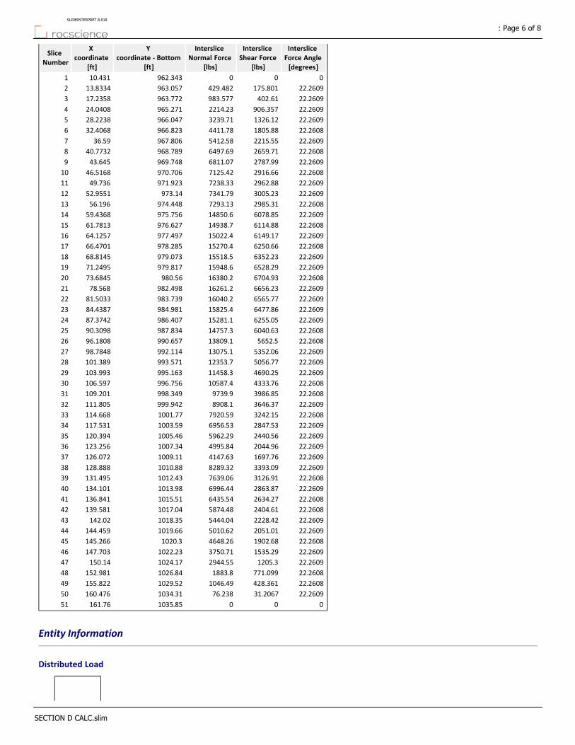
Interslice Force Angle [degrees]
Interslice Shear Force
[lbs]
Interslice Normal Force
[lbs]
Y coordinate ‐ Bottom
[ft]
X coordinate
[ft]
Slice Number
000962.34310.4311
22.2609175.801429.482963.05713.83342
22.2609402.61983.577963.77217.23583
22.2609906.3572214.23965.27124.04084
22.26091326.123239.71966.04728.22385
22.26081805.884411.78966.82332.40686
22.26092215.555412.58967.80636.597
22.26082659.716497.69968.78940.77328
22.26092787.996811.07969.74843.6459
22.26082916.667125.42970.70646.516810
22.26092962.887238.33971.92349.73611
22.26093005.237341.79973.1452.955112
22.26082985.317293.13974.44856.19613
22.26096078.8514850.6975.75659.436814
22.26086114.8814938.7976.62761.781315
22.26096149.1715022.4977.49764.125716
22.26086250.6615270.4978.28566.470117
22.26096352.2315518.5979.07368.814518
22.26096528.2915948.6979.81771.249519
22.26086704.9316380.2980.5673.684520
22.26096656.2316261.2982.49878.56821
22.26096565.7716040.2983.73981.503322
22.26096477.8615825.4984.98184.438723
22.26096255.0515281.1986.40787.374224
22.26086040.6314757.3987.83490.309825
22.26085652.513809.1990.65796.180826
22.26095352.0613075.1992.11498.784827
22.26095056.7712353.7993.571101.38928
22.26094690.2511458.3995.163103.99329
22.26084333.7610587.4996.756106.59730
22.26083986.859739.9998.349109.20131
22.26093646.378908.1999.942111.80532
22.26083242.157920.591001.77114.66833
22.26092847.536956.531003.59117.53134
22.26092440.565962.291005.46120.39435
22.26092044.964995.841007.34123.25636
22.26091697.764147.631009.11126.07237
22.26093393.098289.321010.88128.88838
22.26083126.917639.061012.43131.49539
22.26092863.876996.441013.98134.10140
22.26082634.276435.541015.51136.84141
22.26082404.615874.481017.04139.58142
22.26092228.425444.041018.35142.0243
22.26092051.015010.621019.66144.45944
22.26081902.684648.261020.3145.26645
22.26091535.293750.711022.23147.70346
22.26091205.32944.551024.17150.1447
22.2608771.0991883.81026.84152.98148
22.2608428.3611046.491029.52155.82249
22.260931.206776.2381034.31160.47650
0001035.85161.7651
Entity Information
Distributed Load
: Page 6 of 8SLIDEINTERPRET 8.018
SECTION D CALC.slim

YX
991.67159
975.61159
973.2559
Distributed Load
YX
1023.63128
1011.36128
1008.82128
Tension Crack
YX
1014.33118.438
1022.49133.565
1030.68148.224
1035.79161.143
1037.03173.124
1037.03188.351
External Boundary
YX
9300
930192.917
1041.03192.917
1041.03190.02
1041.03185.448
1041.03172.917
1039.71160.184
1034.3146.506
1026131.64
1024.03128
1013.31108.142
100693.0146
99869.9169
991.81959
985.4947.8212
971.25524.0511
96613.9016
963.39511.768
962.47610.7305
962.1159.9172
961.8569.33256
961.140
Material Boundary
YX
962.1159.9172
965.22824.0511
969.33648.8284
973.2559
982.93484.1616
1002.56116.312
1008.82128
1024.71157.657
1032.02172.917
1041.03190.02
: Page 7 of 8SLIDEINTERPRET 8.018
SECTION D CALC.slim
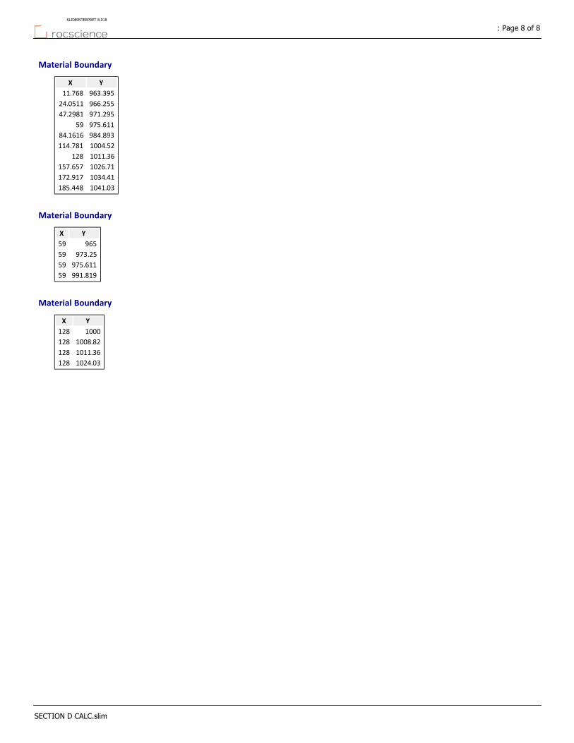
Material Boundary
YX
963.39511.768
966.25524.0511
971.29547.2981
975.61159
984.89384.1616
1004.52114.781
1011.36128
1026.71157.657
1034.41172.917
1041.03185.448
Material Boundary
YX
96559
973.2559
975.61159
991.81959
Material Boundary
YX
1000128
1008.82128
1011.36128
1024.03128
: Page 8 of 8SLIDEINTERPRET 8.018
SECTION D CALC.slim
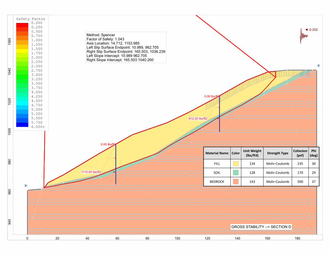
0.00 lbs/ft2
1110.00 lbs/ft2
0.00 lbs/ft2
912.00 lbs/ft2
Material Name ColorUnit Weight(lbs/ 3)
Strength TypeCohesion(psf)
Phi(deg)
FILL 134 Mohr‐Coulomb 235 30
SOIL 128 Mohr‐Coulomb 170 29
BEDROCK 143 Mohr‐Coulomb 500 37
GROSS STABILITY --> SECTION D
Method: SpencerFactor of Safety: 1.043Axis Location: 14.712, 1153.985Left Slip Surface Endpoint: 10.989, 962.705Right Slip Surface Endpoint: 165.503, 1036.239Left Slope Intercept: 10.989 962.705Right Slope Intercept: 165.503 1040.260
0.202
Safety Factor0.0000.2500.5000.7501.0001.2501.5001.7502.0002.2502.5002.7503.0003.2503.5003.7504.0004.2504.5004.7505.0005.2505.5005.7506.000+
1060
1040
1020
1000
980
960
940
0 20 40 60 80 100 120 140 160 180
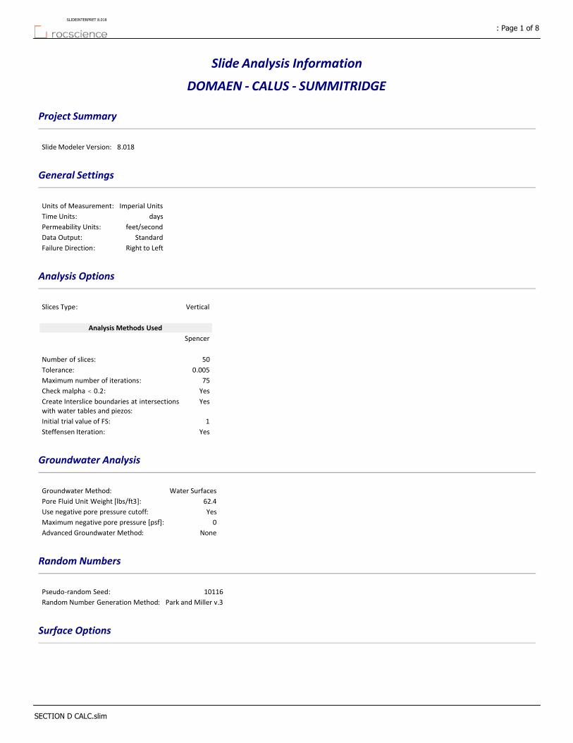
Slide Analysis Information
DOMAEN ‐ CALUS ‐ SUMMITRIDGE
Project Summary
8.018Slide Modeler Version:
General Settings
Imperial UnitsUnits of Measurement:
daysTime Units:
feet/secondPermeability Units:
StandardData Output:
Right to LeftFailure Direction:
Analysis Options
VerticalSlices Type:
Analysis Methods Used
Spencer
50Number of slices:
0.005Tolerance:
75Maximum number of iterations:
YesCheck malpha < 0.2:YesCreate Interslice boundaries at intersections
with water tables and piezos:
1Initial trial value of FS:
YesSteffensen Iteration:
Groundwater Analysis
Water SurfacesGroundwater Method:
62.4Pore Fluid Unit Weight [lbs/ft3]:
YesUse negative pore pressure cutoff:
0Maximum negative pore pressure [psf]:
NoneAdvanced Groundwater Method:
Random Numbers
10116Pseudo‐random Seed:
Park and Miller v.3Random Number Generation Method:
Surface Options
: Page 1 of 8SLIDEINTERPRET 8.018
SECTION D CALC.slim

Cuckoo SearchSearch Method:
8Initial # of Surface Vertices:
500Maximum Iterations:
50Number of Nests:
Not DefinedMinimum Elevation:
Not DefinedMinimum Depth:
Not DefinedMinimum Area:
Not DefinedMinimum Weight:
EnabledConvex Surfaces Only:
Seismic Loading
NoAdvanced seismic analysis:
NoStaged pseudostatic analysis:
0.202Seismic Load Coefficient (Horizontal):
Loading
2 Distributed Loads present
Distributed Load 1
TriangularDistribution:
0Magnitude 1 [psf]:
1110Magnitude 2 [psf]:
Normal to boundaryOrientation:
Distributed Load 2
TriangularDistribution:
0Magnitude 1 [psf]:
912Magnitude 2 [psf]:
Normal to boundaryOrientation:
Tension Crack
Water level: dry
Materials
BEDROCKSOILFILLProperty
Color
Mohr‐CoulombMohr‐CoulombMohr‐CoulombStrength Type
143128134Unit Weight [lbs/ft3]
500170235Cohesion [psf]
372930Friction Angle [°]
NoneNoneNoneWater Surface
000Ru Value
Global Minimums
Method: spencer
: Page 2 of 8SLIDEINTERPRET 8.018
SECTION D CALC.slim
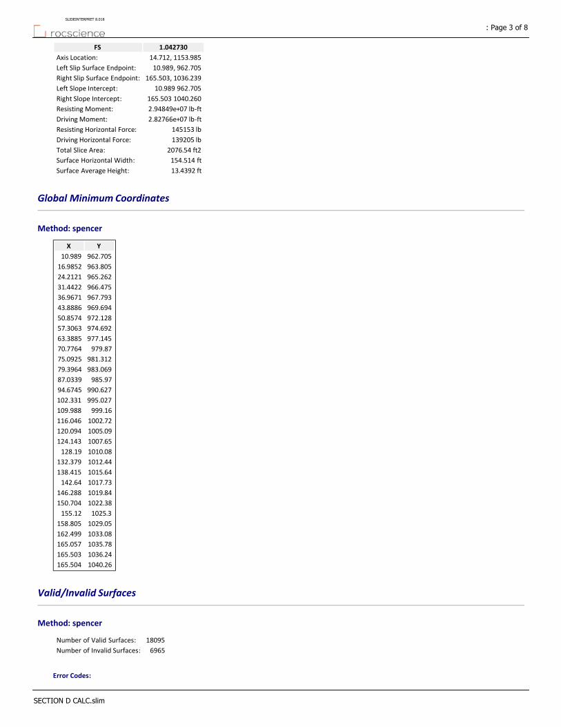
1.042730FS
14.712, 1153.985Axis Location:
10.989, 962.705Left Slip Surface Endpoint:
165.503, 1036.239Right Slip Surface Endpoint:
10.989 962.705Left Slope Intercept:
165.503 1040.260Right Slope Intercept:
2.94849e+07 lb‐ftResisting Moment:
2.82766e+07 lb‐ftDriving Moment:
145153 lbResisting Horizontal Force:
139205 lbDriving Horizontal Force:
2076.54 ft2Total Slice Area:
154.514 ftSurface Horizontal Width:
13.4392 ftSurface Average Height:
Global Minimum Coordinates
Method: spencer
YX
962.70510.989
963.80516.9852
965.26224.2121
966.47531.4422
967.79336.9671
969.69443.8886
972.12850.8574
974.69257.3063
977.14563.3885
979.8770.7764
981.31275.0925
983.06979.3964
985.9787.0339
990.62794.6745
995.027102.331
999.16109.988
1002.72116.046
1005.09120.094
1007.65124.143
1010.08128.19
1012.44132.379
1015.64138.415
1017.73142.64
1019.84146.288
1022.38150.704
1025.3155.12
1029.05158.805
1033.08162.499
1035.78165.057
1036.24165.503
1040.26165.504
Valid/Invalid Surfaces
Method: spencer
18095Number of Valid Surfaces:
6965Number of Invalid Surfaces:
Error Codes:
: Page 3 of 8SLIDEINTERPRET 8.018
SECTION D CALC.slim
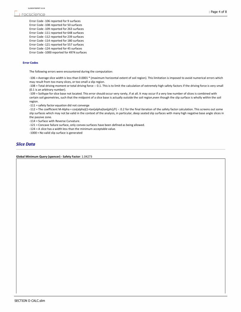
Error Code ‐106 reported for 9 surfacesError Code ‐108 reported for 50 surfacesError Code ‐109 reported for 263 surfacesError Code ‐111 reported for 648 surfacesError Code ‐112 reported for 239 surfacesError Code ‐114 reported for 180 surfacesError Code ‐121 reported for 557 surfacesError Code ‐124 reported for 45 surfacesError Code ‐1000 reported for 4974 surfaces
Error Codes
The following errors were encountered during the computation:
‐106 = Average slice width is less than 0.0001 * (maximum horizontal extent of soil region). This limitation is imposed to avoid numerical errors which may result from too many slices, or too small a slip region.‐108 = Total driving moment or total driving force < 0.1. This is to limit the calculation of extremely high safety factors if the driving force is very small (0.1 is an arbitrary number).‐109 = Soiltype for slice base not located. This error should occur very rarely, if at all. It may occur if a very low number of slices is combined with certain soil geometries, such that the midpoint of a slice base is actually outside the soil region,even though the slip surface is wholly within the soil region.‐111 = safety factor equation did not converge‐112 = The coefficient M‐Alpha = cos(alpha)(1+tan(alpha)tan(phi)/F) < 0.2 for the final iteration of the safety factor calculation. This screens out some slip surfaces which may not be valid in the context of the analysis, in particular, deep seated slip surfaces with many high negative base angle slices in the passive zone.‐114 = Surface with Reverse Curvature.‐121 = Concave failure surface, only convex surfaces have been defined as being allowed.‐124 = A slice has a width less than the minimum acceptable value.‐1000 = No valid slip surface is generated
Slice Data
Global Minimum Query (spencer) ‐ Safety Factor: 1.04273
: Page 4 of 8SLIDEINTERPRET 8.018
SECTION D CALC.slim
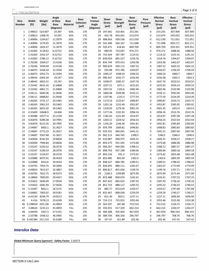
Effective Vertical Stress [psf]
Base Vertical Stress [psf]
Effective Normal Stress [psf]
Pore Pressure [psf]
Base Normal Stress [psf]
Shear Strength [psf]
Shear Stress [psf]
Base Friction Angle
[degrees]
Base Cohesion
[psf]
Base Material
Angle of Slice Base
[degrees]
Weight [lbs]
Width [ft]
Slice Number
307.909307.909253.2910253.291310.401297.68129170SOIL10.397524.0072.998131
593.032593.032513.0740513.074454.401435.7829170SOIL10.3971308.762.998132
711.051711.051612.5390612.539509.536488.65629170SOIL11.39791334.672.408963
820.171820.171711.0980711.098564.167541.04829170SOIL11.39791579.452.408964
929.351929.351809.7090809.709618.83593.47129170SOIL11.39791824.372.408965
1088.561088.56974.2710974.271710.047680.9529170SOIL9.527222118.622.410036
1241.311241.311114.5201114.52787.787755.50429170SOIL9.527222452.372.410037
1394.071394.071254.7601254.76865.527830.05929170SOIL9.527222786.122.410038
1462.671462.671263.5801263.58870.413834.74429170SOIL13.41463569.572.762469
1602.321602.321387.5201387.52939.113900.62929170SOIL13.41463939.042.7624610
1706.591706.591450.0701450.07973.785933.8829170SOIL15.35945428.343.4607311
1860.71860.71584.5401584.541048.331005.3729170SOIL15.35945952.733.4607312
1902.31902.31556.4801556.481032.77990.44729170SOIL19.2476465.393.4844213
2010.532010.531647.7601647.761083.371038.9729170SOIL19.2476855.313.4844214
2034.142034.141625.6301625.631071.11027.2129170SOIL21.68686625.163.2244215
2102.982102.981682.4601682.461102.61057.4229170SOIL21.68686861.713.2244216
3943.463943.463193.1103193.111939.981860.4829170SOIL21.96466685.063.0411117
2224.392224.391777.5401777.541155.31107.9629170SOIL21.96466888.823.0411118
2333.722333.721900.8701900.871223.671173.5329170SOIL20.24655741.172.4626519
2395.922395.921952.8701952.871252.491201.1629170SOIL20.24655901.532.4626520
2453.92453.92001.3502001.351279.361226.9329170SOIL20.24656051.022.4626521
2522.762522.762096.1602096.161331.921277.3429170SOIL18.46810668.94.3160922
2397.282397.281914.9701914.971231.491181.0229170SOIL22.213910577.44.3038823
2413.542413.541956.5301956.531254.521203.1129170SOIL20.79959286.583.8187624
2395.842395.841941.8101941.811246.361195.2929170SOIL20.79959215.353.8187625
2083.832083.831498.8201498.821000.81959.79929170SOIL31.36276002.12.5468726
2007.942007.941441.5101441.51969.041929.33129170SOIL31.36275772.152.5468727
1940.41940.41390.501390.5940.765902.21329170SOIL31.36275567.482.5468728
1928.271928.271405.3101405.31948.975910.08729170SOIL29.88288181.933.8282829
1886.981886.981373.6801373.68931.445893.27529170SOIL29.88287996.843.8282830
1887.271887.271398.1201398.12944.992906.26729170SOIL28.35765243.522.5524731
1869.181869.181384.0601384.06937.198898.79329170SOIL28.35765190.332.5524732
1855.481855.481373.4201373.42931.3893.13629170SOIL28.35765150.072.5524733
1805.591805.591302.601302.6892.04855.48529170SOIL30.45436075.913.0288834
1788.421788.421289.5101289.51884.785848.52729170SOIL30.45436014.63.0288835
1773.991773.991281.0701281.07880.111844.04529170SOIL30.28467954.754.0479236
1707.711707.711199.7601199.76835.036800.81729170SOIL32.38677812.674.0483337
2571.442571.441875.9901875.991209.881160.329170SOIL30.93737652.754.0478538
1707.231707.231242.4101242.41858.676823.48829170SOIL29.44277830.054.1886639
1736.161736.161287.4301287.43883.632847.42229170SOIL27.90265646.093.0182240
1746.531746.531295.5201295.52888.117851.72329170SOIL27.90265681.943.0182241
1797.681797.681359.5701359.57923.619885.7729170SOIL26.31758052.14.2240742
1740.271740.271259.2901259.29868.038832.46729170SOIL30.01817005.023.6486243
1696.941696.941227.1101227.11850.2815.3629170SOIL29.95138246.794.4153944
1533.381533.381055.4601055.46755.053724.11229170SOIL33.42497678.134.41645
1326.751326.75753.5140753.514587.68563.59729170SOIL45.4859329.1380.19895946
1264.371264.37662.2140662.214617.329592.03130235FILL45.48595233.133.4862447
996.543996.543467.6590467.659505.003484.30830235FILL47.51914267.33.6944948
708.76708.76296.7970296.797406.356389.70430235FILL46.59051936.522.5578849
547.42547.42202.460202.46351.89337.4730235FILL45.6289252.2140.44538450
Interslice Data
Global Minimum Query (spencer) ‐ Safety Factor: 1.04273
: Page 5 of 8SLIDEINTERPRET 8.018
SECTION D CALC.slim

Interslice Force Angle [degrees]
Interslice Shear Force
[lbs]
Interslice Normal Force
[lbs]
Y coordinate ‐ Bottom
[ft]
X coordinate
[ft]
Slice Number
000962.70510.9891
32.4001411.178647.91963.25513.98712
32.4001893.9991408.71963.80516.98523
32.40021281.682019.59964.29119.39424
32.40011687.752659.46964.77621.80325
32.40012112.233328.33965.26224.21216
32.40012632.754148.53965.66726.62227
32.40013188.585024.38966.07129.03228
32.40013779.745955.89966.47531.44229
32.40014258.216709.84967.13434.204710
32.40014753.087489.63967.79336.967111
32.40015234.858248.77968.74440.427912
32.40015725.389021.72969.69443.888613
32.40015886.489275.57970.91147.37314
32.40016034.499508.8972.12850.857415
32.40015965.79400.4973.4154.081916
32.40015882.199268.81974.69257.306317
32.400211210.517664.8975.91960.347418
32.400111083.617464.9977.14563.388519
32.411087.117470.5978.05465.851120
32.400211083.417464.5978.96268.313821
32.400111072.817447.9979.8770.776422
32.400111288.717788.1981.31275.092523
32.400111024.717372.1983.06979.396424
32.410950.817255.7984.5283.215225
32.410880.617145.1985.9787.033926
32.40011018716052.1987.52389.580827
32.40029530.0715016.9989.07592.127728
32.48905.7514033.2990.62794.674529
32.40018107.5612775.4992.82798.502830
32.40027336.3711560.2995.027102.33131
32.46910.8210889.7996.405104.88432
32.40026492.2710230.1997.782107.43633
32.40016079.019578.94999.16109.98834
32.40015473.468624.761000.94113.01735
32.40014877.187685.181002.72116.04636
32.40014105.286468.871005.09120.09437
32.40013207.455054.121007.65124.14338
32.40015969.69406.551010.08128.1939
32.40015292.198339.131012.44132.37940
32.40014886.877700.441014.04135.39741
32.40014476.997054.581015.64138.41542
32.40014018.216331.661017.73142.6443
32.40013364.385301.391019.84146.28844
32.40012612.154116.071022.38150.70445
32.41706.322688.731025.3155.1246
32.41638.572581.971025.5155.31947
32.4001788.2751242.121029.05158.80548
32.4001180.127283.8341033.08162.49949
32.400155.605187.61921035.78165.05750
0001036.24165.50351
Entity Information
Distributed Load
: Page 6 of 8SLIDEINTERPRET 8.018
SECTION D CALC.slim
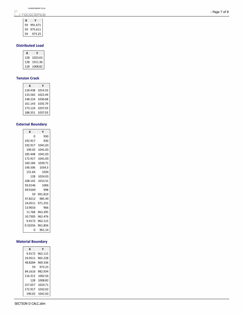
YX
991.67159
975.61159
973.2559
Distributed Load
YX
1023.63128
1011.36128
1008.82128
Tension Crack
YX
1014.33118.438
1022.49133.565
1030.68148.224
1035.79161.143
1037.03173.124
1037.03188.351
External Boundary
YX
9300
930192.917
1041.03192.917
1041.03190.02
1041.03185.448
1041.03172.917
1039.71160.184
1034.3146.506
1026131.64
1024.03128
1013.31108.142
100693.0146
99869.9169
991.81959
985.4947.8212
971.25524.0511
96613.9016
963.39511.768
962.47610.7305
962.1159.9172
961.8569.33256
961.140
Material Boundary
YX
962.1159.9172
965.22824.0511
969.33648.8284
973.2559
982.93484.1616
1002.56116.312
1008.82128
1024.71157.657
1032.02172.917
1041.03190.02
: Page 7 of 8SLIDEINTERPRET 8.018
SECTION D CALC.slim

Material Boundary
YX
963.39511.768
966.25524.0511
971.29547.2981
975.61159
984.89384.1616
1004.52114.781
1011.36128
1026.71157.657
1034.41172.917
1041.03185.448
Material Boundary
YX
96559
973.2559
975.61159
991.81959
Material Boundary
YX
1000128
1008.82128
1011.36128
1024.03128
: Page 8 of 8SLIDEINTERPRET 8.018
SECTION D CALC.slim

1.5861.586
0.00 lbs/ft2
1020.00 lbs/ft2
0.00 lbs/ft2
600.00 lbs/ft2
1.5861.586
Material Name ColorUnit Weight(lbs/ 3)
Strength TypeCohesion(psf)
Phi(deg)
FILL 134 Mohr‐Coulomb 235 30
SOIL 128 Mohr‐Coulomb 170 29
BEDROCK 143 Mohr‐Coulomb 500 37
GROSS STABILITY --> SECTION E
Method: SpencerFactor of Safety: 1.586Center: 127.222, 1060.634Radius: 92.006Left Slip Surface Endpoint: 55.122, 1003.479Right Slip Surface Endpoint: 106.551, 970.980Left Slope Intercept: 55.122 1008.155Right Slope Intercept: 106.551 970.980
1060
1040
1020
1000
980
960
940
-20 0 20 40 60 80 100 120 140 160

Slide Analysis Information
DOMAEN ‐ CALUS ‐ SUMMITRIDGE
Project Summary
8.018Slide Modeler Version:
00h:00m:01.85sCompute Time:
General Settings
Imperial UnitsUnits of Measurement:
daysTime Units:
feet/secondPermeability Units:
StandardData Output:
Left to RightFailure Direction:
Analysis Options
VerticalSlices Type:
Analysis Methods Used
Spencer
50Number of slices:
0.005Tolerance:
75Maximum number of iterations:
YesCheck malpha < 0.2:YesCreate Interslice boundaries at intersections
with water tables and piezos:
1Initial trial value of FS:
YesSteffensen Iteration:
Groundwater Analysis
Water SurfacesGroundwater Method:
62.4Pore Fluid Unit Weight [lbs/ft3]:
YesUse negative pore pressure cutoff:
0Maximum negative pore pressure [psf]:
NoneAdvanced Groundwater Method:
Random Numbers
10116Pseudo‐random Seed:
Park and Miller v.3Random Number Generation Method:
Surface Options
: Page 1 of 7SLIDEINTERPRET 8.018
SECTION E CALC.slim

CircularSurface Type:
Auto Refine SearchSearch Method:
20Divisions along slope:
10Circles per division:
10Number of iterations:
50%Divisions to use in next iteration:
DisabledComposite Surfaces:
Not DefinedMinimum Elevation:
Not DefinedMinimum Depth:
Not DefinedMinimum Area:
Not DefinedMinimum Weight:
Seismic Loading
NoAdvanced seismic analysis:
NoStaged pseudostatic analysis:
Loading
2 Distributed Loads present
Distributed Load 1
TriangularDistribution:
0Magnitude 1 [psf]:
1020Magnitude 2 [psf]:
Normal to boundaryOrientation:
Distributed Load 2
TriangularDistribution:
0Magnitude 1 [psf]:
600Magnitude 2 [psf]:
Normal to boundaryOrientation:
Tension Crack
Water level: dry
Materials
BEDROCKSOILFILLProperty
Color
Mohr‐CoulombMohr‐CoulombMohr‐CoulombStrength Type
143128134Unit Weight [lbs/ft3]
500170235Cohesion [psf]
372930Friction Angle [°]
NoneNoneNoneWater Surface
000Ru Value
Global Minimums
Method: spencer
: Page 2 of 7SLIDEINTERPRET 8.018
SECTION E CALC.slim

1.586140FS
127.222, 1060.634Center:
92.006Radius:
55.122, 1003.479Left Slip Surface Endpoint:
106.551, 970.980Right Slip Surface Endpoint:
55.122 1008.155Left Slope Intercept:
106.551 970.980Right Slope Intercept:
4.32601e+06 lb‐ftResisting Moment:
2.72738e+06 lb‐ftDriving Moment:
39785.5 lbResisting Horizontal Force:
25083.1 lbDriving Horizontal Force:
469.244 ft2Total Slice Area:
51.4291 ftSurface Horizontal Width:
9.12409 ftSurface Average Height:
Valid/Invalid Surfaces
Method: spencer
9947Number of Valid Surfaces:
0Number of Invalid Surfaces:
Slice Data
Global Minimum Query (spencer) ‐ Safety Factor: 1.58614
: Page 3 of 7SLIDEINTERPRET 8.018
SECTION E CALC.slim
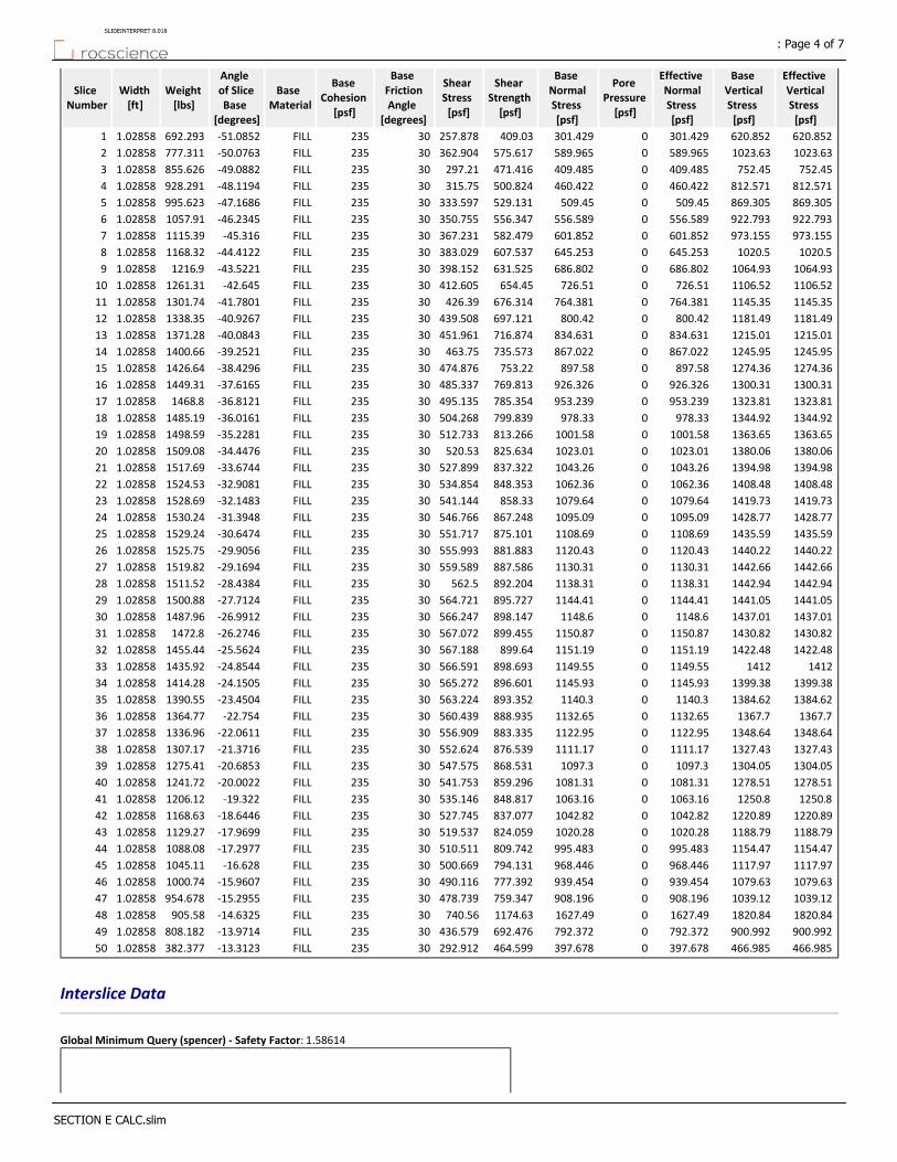
Effective Vertical Stress [psf]
Base Vertical Stress [psf]
Effective Normal Stress [psf]
Pore Pressure [psf]
Base Normal Stress [psf]
Shear Strength [psf]
Shear Stress [psf]
Base Friction Angle
[degrees]
Base Cohesion
[psf]
Base Material
Angle of Slice Base
[degrees]
Weight [lbs]
Width [ft]
Slice Number
620.852620.852301.4290301.429409.03257.87830235FILL‐51.0852692.2931.028581
1023.631023.63589.9650589.965575.617362.90430235FILL‐50.0763777.3111.028582
752.45752.45409.4850409.485471.416297.2130235FILL‐49.0882855.6261.028583
812.571812.571460.4220460.422500.824315.7530235FILL‐48.1194928.2911.028584
869.305869.305509.450509.45529.131333.59730235FILL‐47.1686995.6231.028585
922.793922.793556.5890556.589556.347350.75530235FILL‐46.23451057.911.028586
973.155973.155601.8520601.852582.479367.23130235FILL‐45.3161115.391.028587
1020.51020.5645.2530645.253607.537383.02930235FILL‐44.41221168.321.028588
1064.931064.93686.8020686.802631.525398.15230235FILL‐43.52211216.91.028589
1106.521106.52726.510726.51654.45412.60530235FILL‐42.6451261.311.0285810
1145.351145.35764.3810764.381676.314426.3930235FILL‐41.78011301.741.0285811
1181.491181.49800.420800.42697.121439.50830235FILL‐40.92671338.351.0285812
1215.011215.01834.6310834.631716.874451.96130235FILL‐40.08431371.281.0285813
1245.951245.95867.0220867.022735.573463.7530235FILL‐39.25211400.661.0285814
1274.361274.36897.580897.58753.22474.87630235FILL‐38.42961426.641.0285815
1300.311300.31926.3260926.326769.813485.33730235FILL‐37.61651449.311.0285816
1323.811323.81953.2390953.239785.354495.13530235FILL‐36.81211468.81.0285817
1344.921344.92978.330978.33799.839504.26830235FILL‐36.01611485.191.0285818
1363.651363.651001.5801001.58813.266512.73330235FILL‐35.22811498.591.0285819
1380.061380.061023.0101023.01825.634520.5330235FILL‐34.44761509.081.0285820
1394.981394.981043.2601043.26837.322527.89930235FILL‐33.67441517.691.0285821
1408.481408.481062.3601062.36848.353534.85430235FILL‐32.90811524.531.0285822
1419.731419.731079.6401079.64858.33541.14430235FILL‐32.14831528.691.0285823
1428.771428.771095.0901095.09867.248546.76630235FILL‐31.39481530.241.0285824
1435.591435.591108.6901108.69875.101551.71730235FILL‐30.64741529.241.0285825
1440.221440.221120.4301120.43881.883555.99330235FILL‐29.90561525.751.0285826
1442.661442.661130.3101130.31887.586559.58930235FILL‐29.16941519.821.0285827
1442.941442.941138.3101138.31892.204562.530235FILL‐28.43841511.521.0285828
1441.051441.051144.4101144.41895.727564.72130235FILL‐27.71241500.881.0285829
1437.011437.011148.601148.6898.147566.24730235FILL‐26.99121487.961.0285830
1430.821430.821150.8701150.87899.455567.07230235FILL‐26.27461472.81.0285831
1422.481422.481151.1901151.19899.64567.18830235FILL‐25.56241455.441.0285832
141214121149.5501149.55898.693566.59130235FILL‐24.85441435.921.0285833
1399.381399.381145.9301145.93896.601565.27230235FILL‐24.15051414.281.0285834
1384.621384.621140.301140.3893.352563.22430235FILL‐23.45041390.551.0285835
1367.71367.71132.6501132.65888.935560.43930235FILL‐22.7541364.771.0285836
1348.641348.641122.9501122.95883.335556.90930235FILL‐22.06111336.961.0285837
1327.431327.431111.1701111.17876.539552.62430235FILL‐21.37161307.171.0285838
1304.051304.051097.301097.3868.531547.57530235FILL‐20.68531275.411.0285839
1278.511278.511081.3101081.31859.296541.75330235FILL‐20.00221241.721.0285840
1250.81250.81063.1601063.16848.817535.14630235FILL‐19.3221206.121.0285841
1220.891220.891042.8201042.82837.077527.74530235FILL‐18.64461168.631.0285842
1188.791188.791020.2801020.28824.059519.53730235FILL‐17.96991129.271.0285843
1154.471154.47995.4830995.483809.742510.51130235FILL‐17.29771088.081.0285844
1117.971117.97968.4460968.446794.131500.66930235FILL‐16.6281045.111.0285845
1079.631079.63939.4540939.454777.392490.11630235FILL‐15.96071000.741.0285846
1039.121039.12908.1960908.196759.347478.73930235FILL‐15.2955954.6781.0285847
1820.841820.841627.4901627.491174.63740.5630235FILL‐14.6325905.581.0285848
900.992900.992792.3720792.372692.476436.57930235FILL‐13.9714808.1821.0285849
466.985466.985397.6780397.678464.599292.91230235FILL‐13.3123382.3771.0285850
Interslice Data
Global Minimum Query (spencer) ‐ Safety Factor: 1.58614
: Page 4 of 7SLIDEINTERPRET 8.018
SECTION E CALC.slim

Interslice Force Angle [degrees]
Interslice Shear Force
[lbs]
Interslice Normal Force
[lbs]
Y coordinate ‐ Bottom
[ft]
X coordinate
[ft]
Slice Number
0001003.4855.12221
25.729157.4013119.1161002.256.15082
25.729‐250.54‐519.9091000.9857.17933
25.729‐163.461‐339.207999.78958.20794
25.7292‐65.2529‐135.409998.64259.23655
25.729141.99187.1377997.53260.26516
25.729156.38324.513996.45861.29377
25.7291276.206573.169995.41862.32228
25.7291399.918829.89994.4163.35089
25.729526.111091.76993.43464.379410
25.729653.5031356.12992.48665.40811
25.7291780.9331620.55991.56766.436612
25.7291907.3421882.87990.67567.465213
25.72921031.772141.07989.8168.493714
25.72911153.332393.33988.96969.522315
25.72911271.242638.01988.15370.550916
25.72911384.772873.6987.36171.579517
25.72911493.273098.76986.59172.608118
25.72921596.163312.26985.84373.636719
25.72921692.93513.01985.11774.665220
25.7291783.023700.04984.41175.693821
25.72911866.213872.67983.72676.722422
25.72911942.194030.34983.0677.75123
25.7292010.614172.33982.41478.779624
25.72912071.194298.03981.78679.808125
25.72912123.674406.93981.17780.836726
25.72912167.844498.59980.58581.865327
25.72912203.534572.66980.01182.893928
25.7292230.624628.88979.45483.922529
25.72912249.024667.06978.91484.951130
25.72912258.674687.08978.3985.979631
25.72912259.564688.92977.88287.008232
25.72912251.694672.6977.3988.036833
25.7292235.134638.24976.91389.065434
25.72912209.974586.02976.45290.09435
25.72912176.324516.19976.00691.122536
25.72912134.334429.06975.57592.151137
25.72912084.214325.04975.15893.179738
25.72912026.164204.58974.75594.208339
25.72911960.444068.2974.36795.236940
25.72911887.343916.51973.99396.265541
25.72911807.183750.17973.63297.29442
25.72921720.323569.91973.28598.322643
25.72911627.143376.56972.95199.351244
25.72911528.073170.97972.631100.3845
25.72921423.572954.11972.324101.40846
25.72911314.112726.97972.03102.43747
25.72911200.222490.63971.748103.46648
25.7291231.558480.518971.48104.49449
25.7291113.142234.786971.224105.52350
000970.98106.55151
Entity Information
Distributed Load
: Page 5 of 7SLIDEINTERPRET 8.018
SECTION E CALC.slim
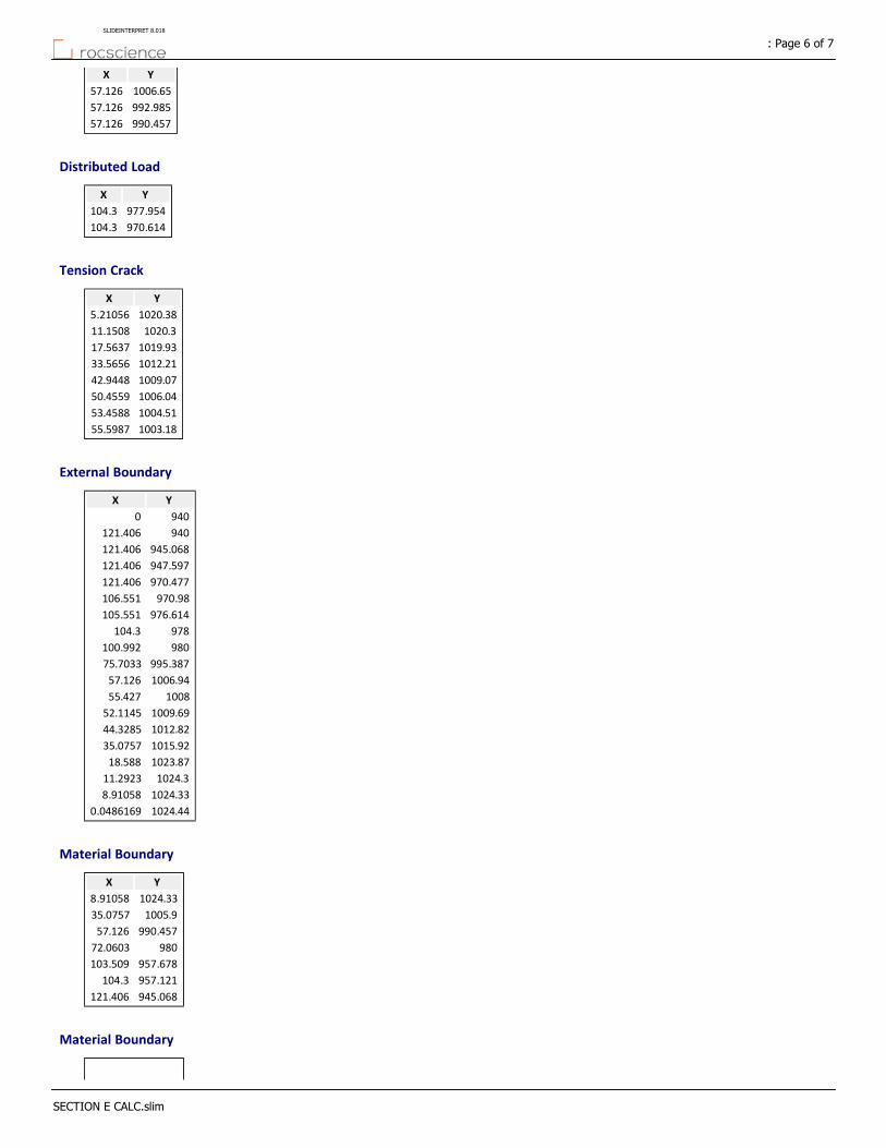
YX
1006.6557.126
992.98557.126
990.45757.126
Distributed Load
YX
977.954104.3
970.614104.3
Tension Crack
YX
1020.385.21056
1020.311.1508
1019.9317.5637
1012.2133.5656
1009.0742.9448
1006.0450.4559
1004.5153.4588
1003.1855.5987
External Boundary
YX
9400
940121.406
945.068121.406
947.597121.406
970.477121.406
970.98106.551
976.614105.551
978104.3
980100.992
995.38775.7033
1006.9457.126
100855.427
1009.6952.1145
1012.8244.3285
1015.9235.0757
1023.8718.588
1024.311.2923
1024.338.91058
1024.440.0486169
Material Boundary
YX
1024.338.91058
1005.935.0757
990.45757.126
98072.0603
957.678103.509
957.121104.3
945.068121.406
Material Boundary
: Page 6 of 7SLIDEINTERPRET 8.018
SECTION E CALC.slim
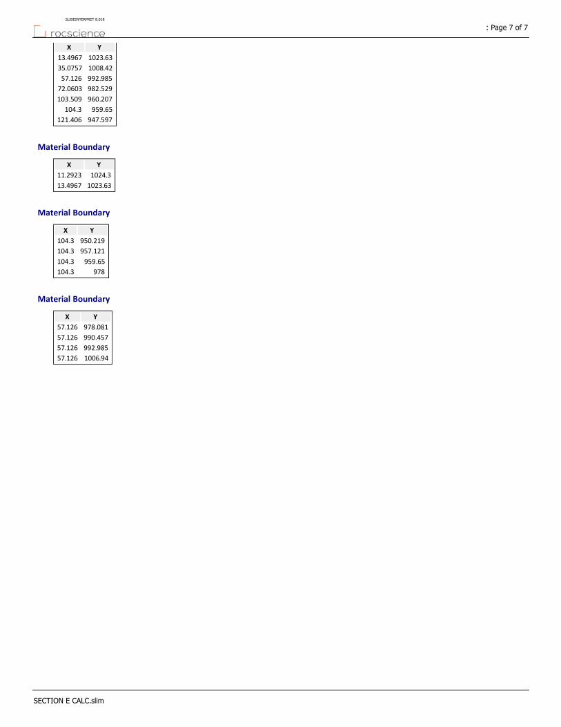
YX
1023.6313.4967
1008.4235.0757
992.98557.126
982.52972.0603
960.207103.509
959.65104.3
947.597121.406
Material Boundary
YX
1024.311.2923
1023.6313.4967
Material Boundary
YX
950.219104.3
957.121104.3
959.65104.3
978104.3
Material Boundary
YX
978.08157.126
990.45757.126
992.98557.126
1006.9457.126
: Page 7 of 7SLIDEINTERPRET 8.018
SECTION E CALC.slim
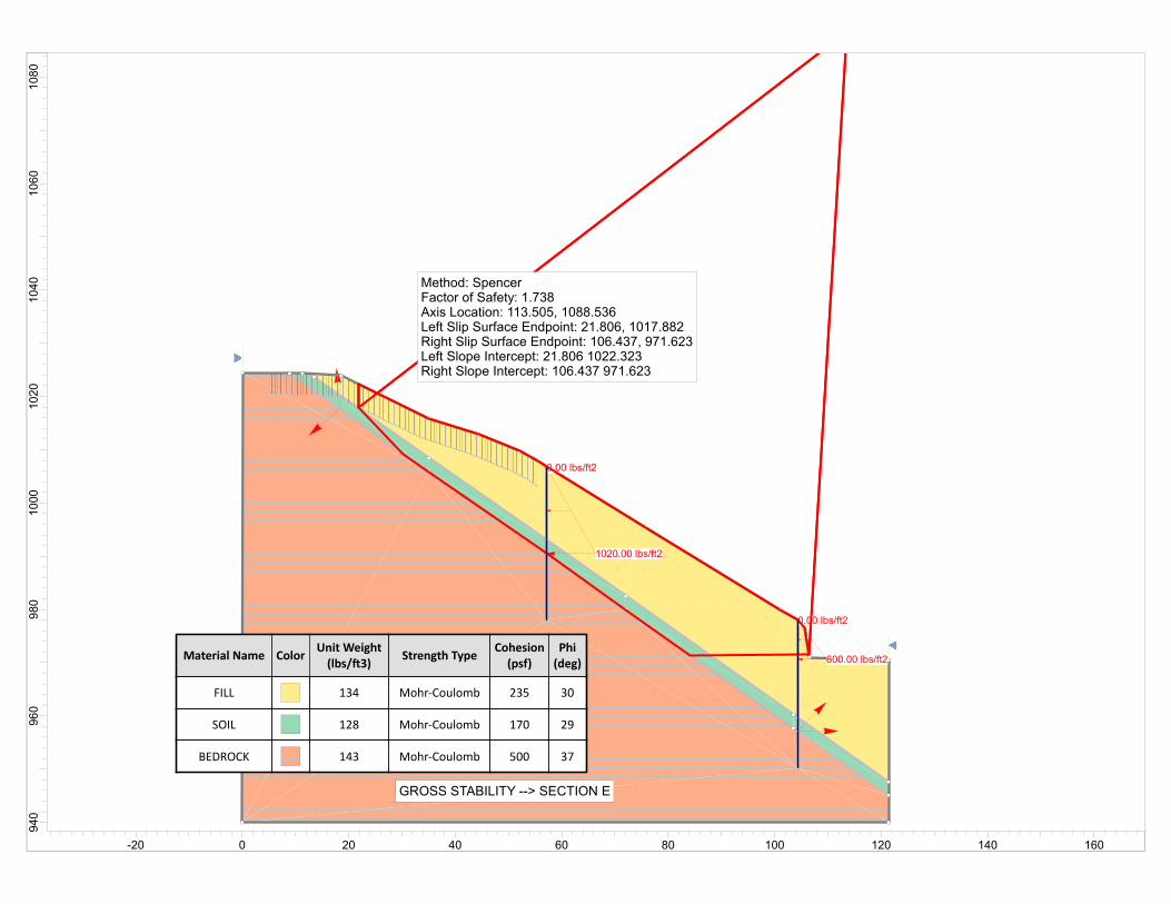
0.00 lbs/ft2
1020.00 lbs/ft2
0.00 lbs/ft2
600.00 lbs/ft2Material Name ColorUnit Weight(lbs/ 3)
Strength TypeCohesion(psf)
Phi(deg)
FILL 134 Mohr‐Coulomb 235 30
SOIL 128 Mohr‐Coulomb 170 29
BEDROCK 143 Mohr‐Coulomb 500 37
GROSS STABILITY --> SECTION E
Method: SpencerFactor of Safety: 1.738Axis Location: 113.505, 1088.536Left Slip Surface Endpoint: 21.806, 1017.882Right Slip Surface Endpoint: 106.437, 971.623Left Slope Intercept: 21.806 1022.323Right Slope Intercept: 106.437 971.623
1080
1060
1040
1020
1000
980
960
940
-20 0 20 40 60 80 100 120 140 160
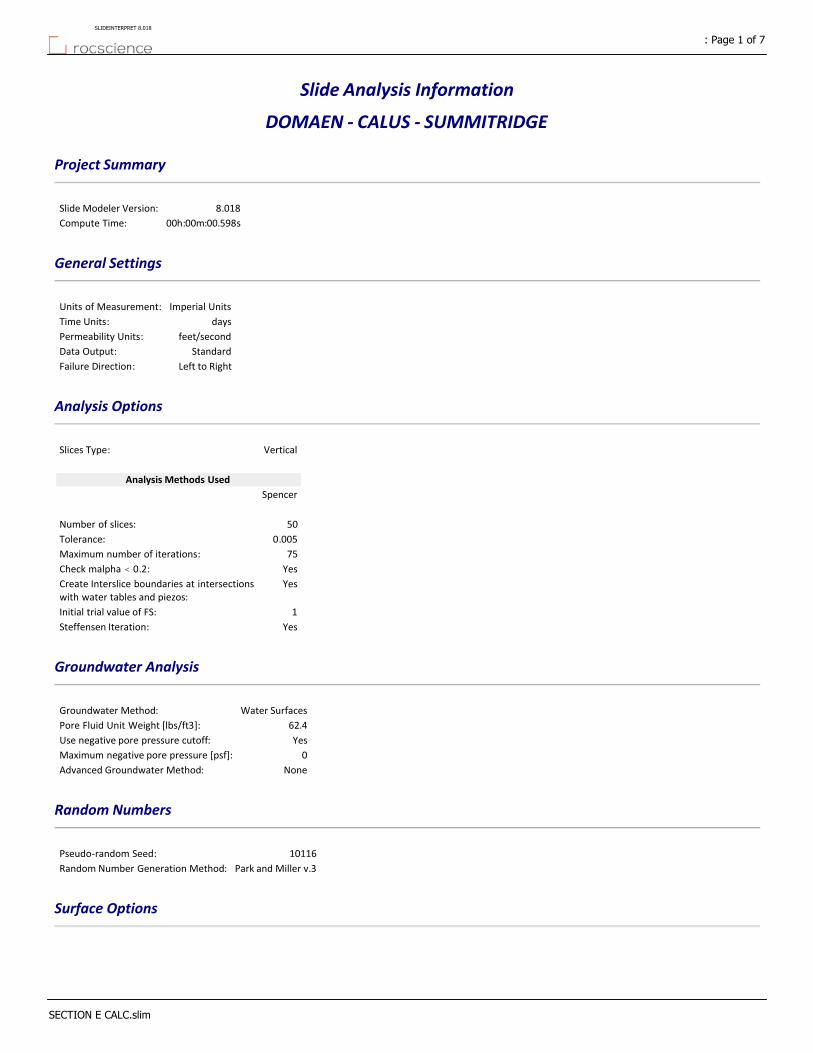
Slide Analysis Information
DOMAEN ‐ CALUS ‐ SUMMITRIDGE
Project Summary
8.018Slide Modeler Version:
00h:00m:00.598sCompute Time:
General Settings
Imperial UnitsUnits of Measurement:
daysTime Units:
feet/secondPermeability Units:
StandardData Output:
Left to RightFailure Direction:
Analysis Options
VerticalSlices Type:
Analysis Methods Used
Spencer
50Number of slices:
0.005Tolerance:
75Maximum number of iterations:
YesCheck malpha < 0.2:YesCreate Interslice boundaries at intersections
with water tables and piezos:
1Initial trial value of FS:
YesSteffensen Iteration:
Groundwater Analysis
Water SurfacesGroundwater Method:
62.4Pore Fluid Unit Weight [lbs/ft3]:
YesUse negative pore pressure cutoff:
0Maximum negative pore pressure [psf]:
NoneAdvanced Groundwater Method:
Random Numbers
10116Pseudo‐random Seed:
Park and Miller v.3Random Number Generation Method:
Surface Options
: Page 1 of 7SLIDEINTERPRET 8.018
SECTION E CALC.slim
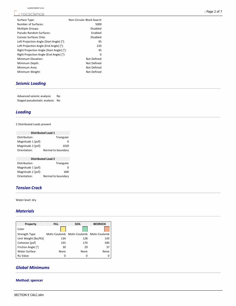
Non‐Circular Block SearchSurface Type:
5000Number of Surfaces:
DisabledMultiple Groups:
EnabledPseudo‐Random Surfaces:
DisabledConvex Surfaces Only:
95Left Projection Angle (Start Angle) [°]:
220Left Projection Angle (End Angle) [°]:
45Right Projection Angle (Start Angle) [°]:
0Right Projection Angle (End Angle) [°]:
Not DefinedMinimum Elevation:
Not DefinedMinimum Depth:
Not DefinedMinimum Area:
Not DefinedMinimum Weight:
Seismic Loading
NoAdvanced seismic analysis:
NoStaged pseudostatic analysis:
Loading
2 Distributed Loads present
Distributed Load 1
TriangularDistribution:
0Magnitude 1 [psf]:
1020Magnitude 2 [psf]:
Normal to boundaryOrientation:
Distributed Load 2
TriangularDistribution:
0Magnitude 1 [psf]:
600Magnitude 2 [psf]:
Normal to boundaryOrientation:
Tension Crack
Water level: dry
Materials
BEDROCKSOILFILLProperty
Color
Mohr‐CoulombMohr‐CoulombMohr‐CoulombStrength Type
143128134Unit Weight [lbs/ft3]
500170235Cohesion [psf]
372930Friction Angle [°]
NoneNoneNoneWater Surface
000Ru Value
Global Minimums
Method: spencer
: Page 2 of 7SLIDEINTERPRET 8.018
SECTION E CALC.slim
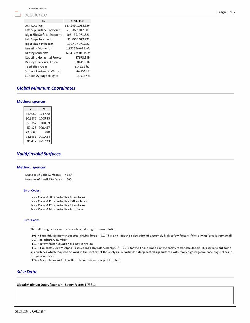
1.738110FS
113.505, 1088.536Axis Location:
21.806, 1017.882Left Slip Surface Endpoint:
106.437, 971.623Right Slip Surface Endpoint:
21.806 1022.323Left Slope Intercept:
106.437 971.623Right Slope Intercept:
1.15539e+07 lb‐ftResisting Moment:
6.64742e+06 lb‐ftDriving Moment:
87673.2 lbResisting Horizontal Force:
50441.8 lbDriving Horizontal Force:
1143.68 ft2Total Slice Area:
84.6311 ftSurface Horizontal Width:
13.5137 ftSurface Average Height:
Global Minimum Coordinates
Method: spencer
YX
1017.8821.8062
1009.2530.3182
1005.935.0757
990.45757.126
98072.0603
971.42484.1451
971.623106.437
Valid/Invalid Surfaces
Method: spencer
4197Number of Valid Surfaces:
803Number of Invalid Surfaces:
Error Codes:
Error Code ‐108 reported for 43 surfacesError Code ‐111 reported for 728 surfacesError Code ‐112 reported for 23 surfacesError Code ‐124 reported for 9 surfaces
Error Codes
The following errors were encountered during the computation:
‐108 = Total driving moment or total driving force < 0.1. This is to limit the calculation of extremely high safety factors if the driving force is very small (0.1 is an arbitrary number).‐111 = safety factor equation did not converge‐112 = The coefficient M‐Alpha = cos(alpha)(1+tan(alpha)tan(phi)/F) < 0.2 for the final iteration of the safety factor calculation. This screens out some slip surfaces which may not be valid in the context of the analysis, in particular, deep seated slip surfaces with many high negative base angle slices in the passive zone.‐124 = A slice has a width less than the minimum acceptable value.
Slice Data
Global Minimum Query (spencer) ‐ Safety Factor: 1.73811
: Page 3 of 7SLIDEINTERPRET 8.018
SECTION E CALC.slim
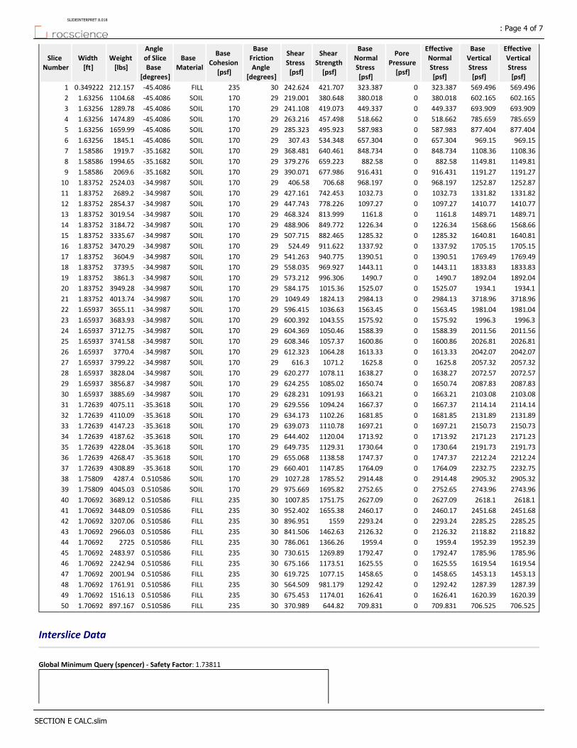
Effective Vertical Stress [psf]
Base Vertical Stress [psf]
Effective Normal Stress [psf]
Pore Pressure [psf]
Base Normal Stress [psf]
Shear Strength [psf]
Shear Stress [psf]
Base Friction Angle
[degrees]
Base Cohesion
[psf]
Base Material
Angle of Slice Base
[degrees]
Weight [lbs]
Width [ft]
Slice Number
569.496569.496323.3870323.387421.707242.62430235FILL‐45.4086212.1570.3492221
602.165602.165380.0180380.018380.648219.00129170SOIL‐45.40861104.681.632562
693.909693.909449.3370449.337419.073241.10829170SOIL‐45.40861289.781.632563
785.659785.659518.6620518.662457.498263.21629170SOIL‐45.40861474.891.632564
877.404877.404587.9830587.983495.923285.32329170SOIL‐45.40861659.991.632565
969.15969.15657.3040657.304534.348307.4329170SOIL‐45.40861845.11.632566
1108.361108.36848.7340848.734640.461368.48129170SOIL‐35.16821919.71.585867
1149.811149.81882.580882.58659.223379.27629170SOIL‐35.16821994.651.585868
1191.271191.27916.4310916.431677.986390.07129170SOIL‐35.16822069.61.585869
1252.871252.87968.1970968.197706.68406.5829170SOIL‐34.99872524.031.8375210
1331.821331.821032.7301032.73742.453427.16129170SOIL‐34.99872689.21.8375211
1410.771410.771097.2701097.27778.226447.74329170SOIL‐34.99872854.371.8375212
1489.711489.711161.801161.8813.999468.32429170SOIL‐34.99873019.541.8375213
1568.661568.661226.3401226.34849.772488.90629170SOIL‐34.99873184.721.8375214
1640.811640.811285.3201285.32882.465507.71529170SOIL‐34.99873335.671.8375215
1705.151705.151337.9201337.92911.622524.4929170SOIL‐34.99873470.291.8375216
1769.491769.491390.5101390.51940.775541.26329170SOIL‐34.99873604.91.8375217
1833.831833.831443.1101443.11969.927558.03529170SOIL‐34.99873739.51.8375218
1892.041892.041490.701490.7996.306573.21229170SOIL‐34.99873861.31.8375219
1934.11934.11525.0701525.071015.36584.17529170SOIL‐34.99873949.281.8375220
3718.963718.962984.1302984.131824.131049.4929170SOIL‐34.99874013.741.8375221
1981.041981.041563.4501563.451036.63596.41529170SOIL‐34.99873655.111.6593722
1996.31996.31575.9201575.921043.55600.39229170SOIL‐34.99873683.931.6593723
2011.562011.561588.3901588.391050.46604.36929170SOIL‐34.99873712.751.6593724
2026.812026.811600.8601600.861057.37608.34629170SOIL‐34.99873741.581.6593725
2042.072042.071613.3301613.331064.28612.32329170SOIL‐34.99873770.41.6593726
2057.322057.321625.801625.81071.2616.329170SOIL‐34.99873799.221.6593727
2072.572072.571638.2701638.271078.11620.27729170SOIL‐34.99873828.041.6593728
2087.832087.831650.7401650.741085.02624.25529170SOIL‐34.99873856.871.6593729
2103.082103.081663.2101663.211091.93628.23129170SOIL‐34.99873885.691.6593730
2114.142114.141667.3701667.371094.24629.55629170SOIL‐35.36184075.111.7263931
2131.892131.891681.8501681.851102.26634.17329170SOIL‐35.36184110.091.7263932
2150.732150.731697.2101697.211110.78639.07329170SOIL‐35.36184147.231.7263933
2171.232171.231713.9201713.921120.04644.40229170SOIL‐35.36184187.621.7263934
2191.732191.731730.6401730.641129.31649.73529170SOIL‐35.36184228.041.7263935
2212.242212.241747.3701747.371138.58655.06829170SOIL‐35.36184268.471.7263936
2232.752232.751764.0901764.091147.85660.40129170SOIL‐35.36184308.891.7263937
2905.322905.322914.4802914.481785.521027.2829170SOIL0.5105864287.41.7580938
2743.962743.962752.6502752.651695.82975.66929170SOIL0.5105864045.031.7580939
2618.12618.12627.0902627.091751.751007.8530235FILL0.5105863689.121.7069240
2451.682451.682460.1702460.171655.38952.40230235FILL0.5105863448.091.7069241
2285.252285.252293.2402293.241559896.95130235FILL0.5105863207.061.7069242
2118.822118.822126.3202126.321462.63841.50630235FILL0.5105862966.031.7069243
1952.391952.391959.401959.41366.26786.06130235FILL0.51058627251.7069244
1785.961785.961792.4701792.471269.89730.61530235FILL0.5105862483.971.7069245
1619.541619.541625.5501625.551173.51675.16630235FILL0.5105862242.941.7069246
1453.131453.131458.6501458.651077.15619.72530235FILL0.5105862001.941.7069247
1287.391287.391292.4201292.42981.179564.50930235FILL0.5105861761.911.7069248
1620.391620.391626.4101626.411174.01675.45330235FILL0.5105861516.131.7069249
706.525706.525709.8310709.831644.82370.98930235FILL0.510586897.1671.7069250
Interslice Data
Global Minimum Query (spencer) ‐ Safety Factor: 1.73811
: Page 4 of 7SLIDEINTERPRET 8.018
SECTION E CALC.slim

Interslice Force Angle [degrees]
Interslice Shear Force
[lbs]
Interslice Normal Force
[lbs]
Y coordinate ‐ Bottom
[ft]
X coordinate
[ft]
Slice Number
0001017.8821.80621
23.902213.177529.73361017.5322.15542
23.9022133.454301.1251015.8723.78793
23.9022288.594651.1811014.2225.42054
23.9023478.5971079.91012.5627.05315
23.9022703.4631587.291010.928.68566
23.9022963.1922173.341009.2530.31827
23.90231124.232536.71008.1331.9048
23.90221294.432920.741007.0133.48999
23.90221473.83325.471005.935.075710
23.90231694.43823.221004.6136.913311
23.90221935.014366.141003.3238.750812
23.90232195.654954.231002.0440.588313
23.90232476.35587.491000.7542.425814
23.90232776.976265.92999.46344.263315
23.90233095.946985.64998.17646.100916
23.90223431.227742.17996.8947.938417
23.90233782.828535.51995.60349.775918
23.90234150.739365.66994.31651.613419
23.90234533.410229.1993.0353.450920
23.90234926.7411116.6991.74355.288421
23.90232112.614766.86990.45757.12622
23.90222478.565592.6989.29558.785323
23.90222848.016426.22988.13360.444724
23.90223220.957267.72986.97162.104125
23.90223597.388117.1985.80963.763526
23.90223977.318974.37984.64765.422827
23.90224360.739839.51983.48667.082228
23.90234747.6510712.5982.32468.741629
23.90225138.0611593.5981.16270.40130
23.90235531.9612482.298072.060331
23.90225955.0813437978.77573.786732
23.90226382.5214401.5977.5575.513133
23.90226814.5615376.3976.32577.239534
23.90237251.5916362.4975.09978.965935
23.90227693.6117359.8973.87480.692336
23.90238140.6318368.4972.64982.418737
23.90238592.6419388.3971.42484.145138
23.90227771.1117534.7971.4485.903139
23.90236990.9715774.3971.45587.661240
23.90226210.0114012.2971.47189.368141
23.90235472.1612347.3971.48691.075142
23.90234777.4310779.7971.50192.78243
23.90234125.829309.45971.51694.488944
23.90233517.327936.44971.53196.195845
23.90232951.946660.72971.54797.902746
23.90232429.675482.28971.56299.609647
23.90221950.514401.12971.577101.31748
23.90221514.293416.83971.592103.02349
23.9023261.349589.705971.607104.7350
000971.623106.43751
Entity Information
Distributed Load
: Page 5 of 7SLIDEINTERPRET 8.018
SECTION E CALC.slim
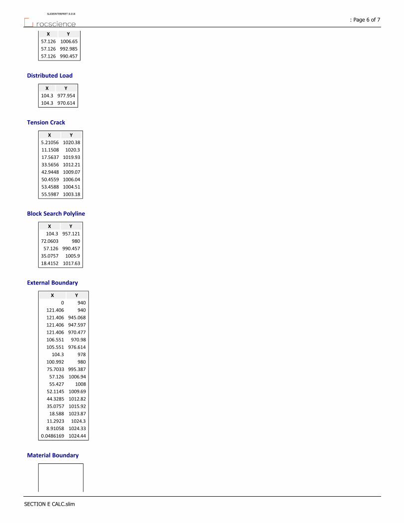
YX
1006.6557.126
992.98557.126
990.45757.126
Distributed Load
YX
977.954104.3
970.614104.3
Tension Crack
YX
1020.385.21056
1020.311.1508
1019.9317.5637
1012.2133.5656
1009.0742.9448
1006.0450.4559
1004.5153.4588
1003.1855.5987
Block Search Polyline
YX
957.121104.3
98072.0603
990.45757.126
1005.935.0757
1017.6318.4152
External Boundary
YX
9400
940121.406
945.068121.406
947.597121.406
970.477121.406
970.98106.551
976.614105.551
978104.3
980100.992
995.38775.7033
1006.9457.126
100855.427
1009.6952.1145
1012.8244.3285
1015.9235.0757
1023.8718.588
1024.311.2923
1024.338.91058
1024.440.0486169
Material Boundary
: Page 6 of 7SLIDEINTERPRET 8.018
SECTION E CALC.slim
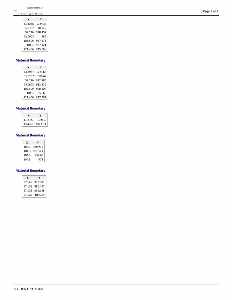
YX
1024.338.91058
1005.935.0757
990.45757.126
98072.0603
957.678103.509
957.121104.3
945.068121.406
Material Boundary
YX
1023.6313.4967
1008.4235.0757
992.98557.126
982.52972.0603
960.207103.509
959.65104.3
947.597121.406
Material Boundary
YX
1024.311.2923
1023.6313.4967
Material Boundary
YX
950.219104.3
957.121104.3
959.65104.3
978104.3
Material Boundary
YX
978.08157.126
990.45757.126
992.98557.126
1006.9457.126
: Page 7 of 7SLIDEINTERPRET 8.018
SECTION E CALC.slim

0.00 lbs/ft2
1020.00 lbs/ft2
0.00 lbs/ft2
800.00 lbs/ft2Material Name ColorUnit Weight(lbs/ 3)
Strength TypeCohesion(psf)
Phi(deg)
FILL 134 Mohr‐Coulomb 235 30
SOIL 128 Mohr‐Coulomb 170 29
BEDROCK 143 Mohr‐Coulomb 500 37
GROSS STABILITY --> SECTION E
Method: SpencerFactor of Safety: 1.058Axis Location: 115.331, 1085.703Left Slip Surface Endpoint: 19.029, 1019.221Right Slip Surface Endpoint: 106.551, 970.980Left Slope Intercept: 19.029 1023.662Right Slope Intercept: 106.551 970.980
0.202
1010
6010
4010
2010
0098
096
094
0
-20 0 20 40 60 80 100 120 140 160

Slide Analysis Information
DOMAEN ‐ CALUS ‐ SUMMITRIDGE
Project Summary
8.018Slide Modeler Version:
00h:00m:07.617sCompute Time:
General Settings
Imperial UnitsUnits of Measurement:
daysTime Units:
feet/secondPermeability Units:
StandardData Output:
Left to RightFailure Direction:
Analysis Options
VerticalSlices Type:
Analysis Methods Used
Spencer
50Number of slices:
0.005Tolerance:
75Maximum number of iterations:
YesCheck malpha < 0.2:YesCreate Interslice boundaries at intersections
with water tables and piezos:
1Initial trial value of FS:
YesSteffensen Iteration:
Groundwater Analysis
Water SurfacesGroundwater Method:
62.4Pore Fluid Unit Weight [lbs/ft3]:
YesUse negative pore pressure cutoff:
0Maximum negative pore pressure [psf]:
NoneAdvanced Groundwater Method:
Random Numbers
10116Pseudo‐random Seed:
Park and Miller v.3Random Number Generation Method:
Surface Options
: Page 1 of 8SLIDEINTERPRET 8.018
SECTION E CALC.slim
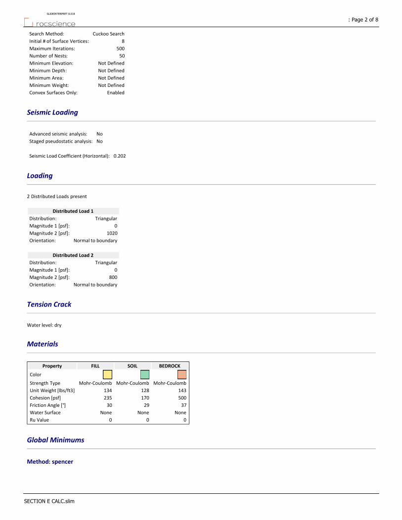
Cuckoo SearchSearch Method:
8Initial # of Surface Vertices:
500Maximum Iterations:
50Number of Nests:
Not DefinedMinimum Elevation:
Not DefinedMinimum Depth:
Not DefinedMinimum Area:
Not DefinedMinimum Weight:
EnabledConvex Surfaces Only:
Seismic Loading
NoAdvanced seismic analysis:
NoStaged pseudostatic analysis:
0.202Seismic Load Coefficient (Horizontal):
Loading
2 Distributed Loads present
Distributed Load 1
TriangularDistribution:
0Magnitude 1 [psf]:
1020Magnitude 2 [psf]:
Normal to boundaryOrientation:
Distributed Load 2
TriangularDistribution:
0Magnitude 1 [psf]:
800Magnitude 2 [psf]:
Normal to boundaryOrientation:
Tension Crack
Water level: dry
Materials
BEDROCKSOILFILLProperty
Color
Mohr‐CoulombMohr‐CoulombMohr‐CoulombStrength Type
143128134Unit Weight [lbs/ft3]
500170235Cohesion [psf]
372930Friction Angle [°]
NoneNoneNoneWater Surface
000Ru Value
Global Minimums
Method: spencer
: Page 2 of 8SLIDEINTERPRET 8.018
SECTION E CALC.slim
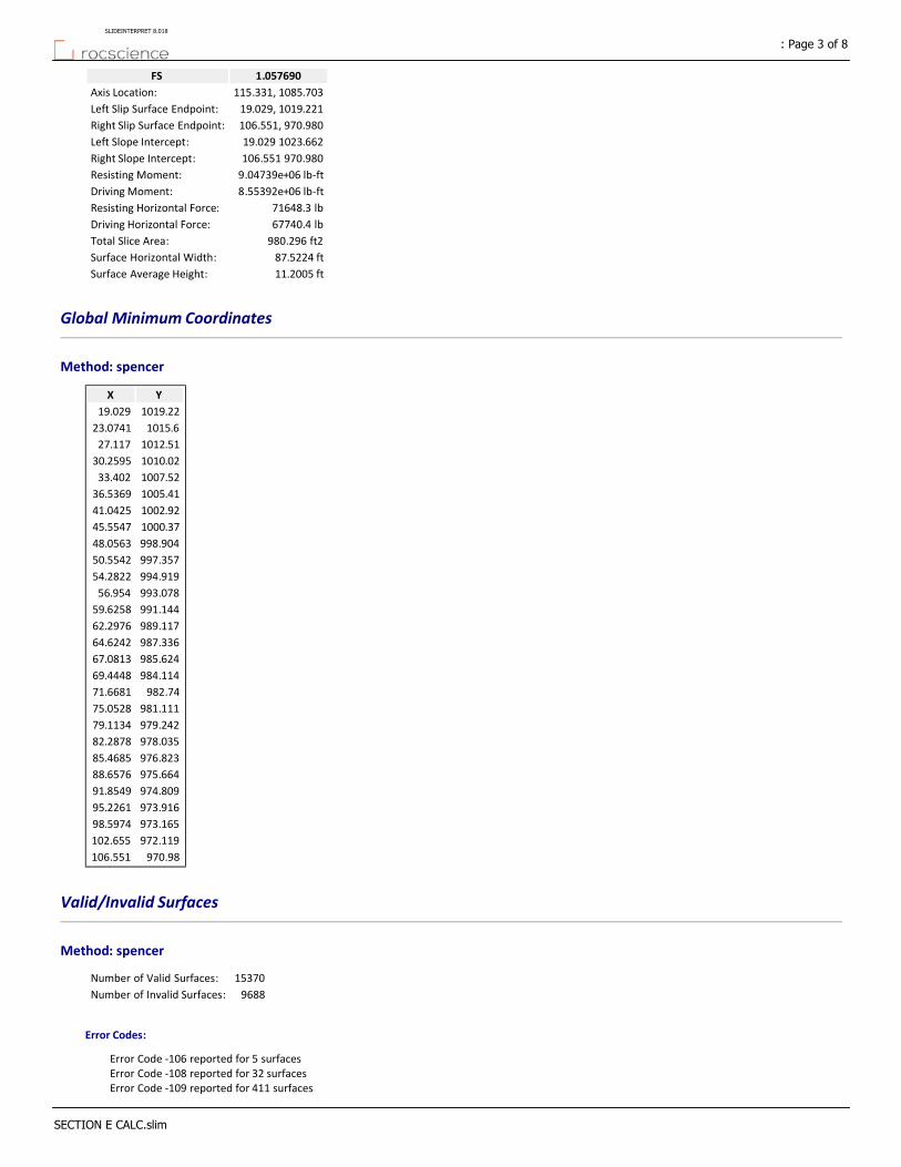
1.057690FS
115.331, 1085.703Axis Location:
19.029, 1019.221Left Slip Surface Endpoint:
106.551, 970.980Right Slip Surface Endpoint:
19.029 1023.662Left Slope Intercept:
106.551 970.980Right Slope Intercept:
9.04739e+06 lb‐ftResisting Moment:
8.55392e+06 lb‐ftDriving Moment:
71648.3 lbResisting Horizontal Force:
67740.4 lbDriving Horizontal Force:
980.296 ft2Total Slice Area:
87.5224 ftSurface Horizontal Width:
11.2005 ftSurface Average Height:
Global Minimum Coordinates
Method: spencer
YX
1019.2219.029
1015.623.0741
1012.5127.117
1010.0230.2595
1007.5233.402
1005.4136.5369
1002.9241.0425
1000.3745.5547
998.90448.0563
997.35750.5542
994.91954.2822
993.07856.954
991.14459.6258
989.11762.2976
987.33664.6242
985.62467.0813
984.11469.4448
982.7471.6681
981.11175.0528
979.24279.1134
978.03582.2878
976.82385.4685
975.66488.6576
974.80991.8549
973.91695.2261
973.16598.5974
972.119102.655
970.98106.551
Valid/Invalid Surfaces
Method: spencer
15370Number of Valid Surfaces:
9688Number of Invalid Surfaces:
Error Codes:
Error Code ‐106 reported for 5 surfacesError Code ‐108 reported for 32 surfacesError Code ‐109 reported for 411 surfaces
: Page 3 of 8SLIDEINTERPRET 8.018
SECTION E CALC.slim
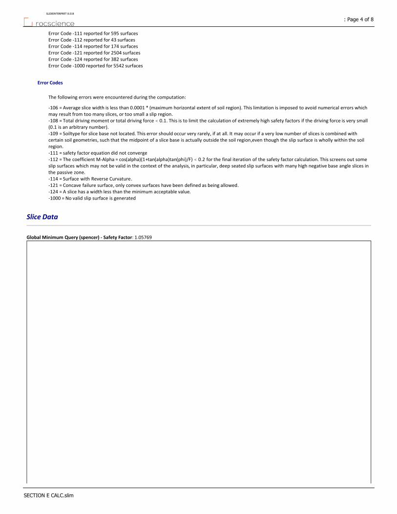
Error Code ‐111 reported for 595 surfacesError Code ‐112 reported for 43 surfacesError Code ‐114 reported for 174 surfacesError Code ‐121 reported for 2504 surfacesError Code ‐124 reported for 382 surfacesError Code ‐1000 reported for 5542 surfaces
Error Codes
The following errors were encountered during the computation:
‐106 = Average slice width is less than 0.0001 * (maximum horizontal extent of soil region). This limitation is imposed to avoid numerical errors which may result from too many slices, or too small a slip region.‐108 = Total driving moment or total driving force < 0.1. This is to limit the calculation of extremely high safety factors if the driving force is very small (0.1 is an arbitrary number).‐109 = Soiltype for slice base not located. This error should occur very rarely, if at all. It may occur if a very low number of slices is combined with certain soil geometries, such that the midpoint of a slice base is actually outside the soil region,even though the slip surface is wholly within the soil region.‐111 = safety factor equation did not converge‐112 = The coefficient M‐Alpha = cos(alpha)(1+tan(alpha)tan(phi)/F) < 0.2 for the final iteration of the safety factor calculation. This screens out some slip surfaces which may not be valid in the context of the analysis, in particular, deep seated slip surfaces with many high negative base angle slices in the passive zone.‐114 = Surface with Reverse Curvature.‐121 = Concave failure surface, only convex surfaces have been defined as being allowed.‐124 = A slice has a width less than the minimum acceptable value.‐1000 = No valid slip surface is generated
Slice Data
Global Minimum Query (spencer) ‐ Safety Factor: 1.05769
: Page 4 of 8SLIDEINTERPRET 8.018
SECTION E CALC.slim

Effective Vertical Stress [psf]
Base Vertical Stress [psf]
Effective Normal Stress [psf]
Pore Pressure [psf]
Base Normal Stress [psf]
Shear Strength [psf]
Shear Stress [psf]
Base Friction Angle
[degrees]
Base Cohesion
[psf]
Base Material
Angle of Slice Base
[degrees]
Weight [lbs]
Width [ft]
Slice Number
583.978583.978299.7750299.775336.168317.83229170SOIL‐41.80281307.942.022541
661.121661.121352.3030352.303365.285345.36129170SOIL‐41.80281529.122.022542
755.903755.903451.7450451.745420.407397.47729170SOIL‐37.42411715.562.021433
812.398812.398492.0690492.069442.758418.60829170SOIL‐37.42411869.042.021434
856.193856.193514.6420514.642455.272430.4429170SOIL‐38.43171563.291.571265
903.746903.746548.2290548.229473.888448.04129170SOIL‐38.43171664.961.571266
951.294951.294581.8060581.806492.5465.63729170SOIL‐38.43241766.631.571267
998.849998.849615.3930615.393511.118483.2429170SOIL‐38.43241868.31.571268
1087.51087.5723.3880723.388570.979539.83629170SOIL‐33.9991946.341.567439
1129.481129.48754.4090754.409588.174556.09329170SOIL‐33.9992031.11.5674310
1256.781256.78906.2990906.299672.37635.69729170SOIL‐28.86973075.432.2528211
1312.621312.62949.6140949.614696.381658.39829170SOIL‐28.86973227.022.2528212
1348.891348.89969.5340969.534707.422668.83729170SOIL‐29.56112241.171.5040813
1388.331388.33999.9410999.941724.276684.77229170SOIL‐29.56112313.321.5040814
1424.051424.051027.4801027.48739.54699.20329170SOIL‐29.56112378.681.5040815
1451.021451.021039.0101039.01745.93705.24429170SOIL‐30.29424078.072.5015816
1480.11480.11042.3601042.36747.793707.00629170SOIL‐31.76324242.282.4979117
1509.021509.021045.5101045.51749.538708.65629170SOIL‐33.18713292.641.8639718
1545.061545.061072.3501072.35764.415722.72129170SOIL‐33.18713378.271.8639719
1547.031547.031055.2601055.26754.938713.76129170SOIL‐34.56612466.861.3359120
1562.021562.021066.2701066.27761.047719.53729170SOIL‐34.56612492.851.3359121
4633.024633.023274.4203274.421985.041876.7729170SOIL‐35.90082512.961.3359122
1563.691563.691049.2701049.27751.621710.62529170SOIL‐35.90082537.061.3359123
1557.11557.11026.801026.8739.163698.84729170SOIL‐37.1922565.151.3359124
1575.021575.021039.6201039.62746.269705.56529170SOIL‐37.1922597.231.3359125
1596.171596.171051.4801051.48752.846711.78329170SOIL‐37.42514602.092.3265926
1668.841668.841140.3301140.33802.095758.34629170SOIL‐34.87384944.192.4570427
1726.371726.371216.3601216.36844.24798.19229170SOIL‐32.57684792.552.3635228
1746.951746.951244.7601244.76859.982813.07629170SOIL‐31.70124514.872.2232929
1882.671882.671441.5401441.54969.06916.20429170SOIL‐25.7097582.1750.28705530
1940.791940.791452.1601452.161073.41014.8630235FILL‐25.70973114.741.5488631
1915.161915.161431.8701431.871061.691003.7830235FILL‐25.70973069.551.5488632
1909.511909.511444.4401444.441068.951010.6430235FILL‐24.71043951.012.0302633
1873.411873.411415.5901415.591052.29994.89530235FILL‐24.71043868.722.0302634
1939.221939.221536.0101536.011121.811060.6330235FILL‐20.81512953.971.5872435
1893.41893.41498.0601498.061099.91039.9130235FILL‐20.81512876.911.5872436
1846.111846.111457.9701457.971076.761018.0330235FILL‐20.87012805.451.5903537
1800.461800.461420.1801420.181054.94997.40330235FILL‐20.87012728.451.5903538
1777.111777.111415.6601415.661052.33994.93430235FILL‐19.96562655.291.5945539
1727.011727.011373.8601373.861028.2972.11430235FILL‐19.96562571.761.5945540
1809.431809.431527.1701527.171116.711055.830235FILL‐14.96772478.071.5986441
1733.491733.491460.901460.91078.451019.6330235FILL‐14.96772361.261.5986442
1658.671658.671397.5101397.511041.85985.02630235FILL‐14.84952362.781.6856143
1577.921577.921326.9601326.961001.12946.51630235FILL‐14.84952232.071.6856144
1556.211556.211343.4101343.411010.62955.49530235FILL‐12.55522093.281.6856145
1461.581461.581259.0401259.04961.908909.44230235FILL‐12.55521946.411.6856146
1315.781315.781103.3701103.37872.033824.46930235FILL‐14.44672157.682.0289247
1216.11216.11015.9801015.98821.578776.76630235FILL‐14.44671964.872.0289248
2128.082128.081778.9901778.991262.11193.2630235FILL‐16.30671712.231.9481149
760.047760.047599.340599.34581.03549.33930235FILL‐16.30671085.661.9481150
Interslice Data
Global Minimum Query (spencer) ‐ Safety Factor: 1.05769
: Page 5 of 8SLIDEINTERPRET 8.018
SECTION E CALC.slim

Interslice Force Angle [degrees]
Interslice Shear Force
[lbs]
Interslice Normal Force
[lbs]
Y coordinate ‐ Bottom
[ft]
X coordinate
[ft]
Slice Number
0001019.2219.0291
37.7914126.803163.5241017.4121.05152
37.7915318.742411.0461015.623.07413
37.7915506.279652.8921014.0625.09554
37.7914733.099945.3971012.5127.1175
37.7915951.0721226.491011.2628.68826
37.79141195.991542.341010.0230.25957
37.79151467.881892.961008.7731.83078
37.79151766.712278.331007.5233.4029
37.79152008.472590.11006.4734.969410
37.79142269.172926.31005.4136.536911
37.79142513.283241.11004.1738.789712
37.79152783.23589.181002.9241.042513
37.79152995.5338631002.0742.546614
37.79143220.694153.371001.2244.050715
37.79143457.474458.721000.3745.554716
37.79153905.685036.72998.90448.056317
37.79144450.785739.68997.35750.554218
37.79144930.646358.51996.13852.418219
37.79155428.967001.13994.91954.282220
37.79155829.137517.18993.99955.618121
37.79146235.248040.91993.07856.95422
37.79152558.973300.01992.11158.289923
37.79143007.063877.88991.14459.625824
37.79153492.054503.31990.1360.961725
37.79143985.185139.25989.11762.297626
37.79144873.586284.92987.33664.624227
37.79155717.347373.02985.62467.081328
37.79156429.568291.49984.11469.444829
37.79157060.459105.08982.7471.668130
37.79157102.199158.91982.60271.955131
37.79147210.939299.14981.85773.50432
37.79147314.159432.26981.11175.052833
37.79157388.369527.95980.17777.083134
37.79147453.579612.05979.24279.113435
37.79157329.569452.12978.63980.700636
37.79157201.219286.6978.03582.287837
37.79157070.79118.29977.42983.878238
37.79146935.798944.33976.82385.468539
37.79146757.48714.28976.24387.063140
37.79156575.378479.52975.66488.657641
37.79146160.827944.93975.23790.256342
37.79145750.857416.24974.80991.854943
37.79155317.746857.7974.36293.540544
37.79144890.046306.15973.91695.226145
37.79144360.065622.69973.5496.911846
37.79143842.714955.52973.16598.597447
37.79153330.764295.31972.642100.62648
37.79152828.243647.26972.119102.65549
37.7915394.507508.751971.549104.60350
000970.98106.55151
Entity Information
Distributed Load
: Page 6 of 8SLIDEINTERPRET 8.018
SECTION E CALC.slim
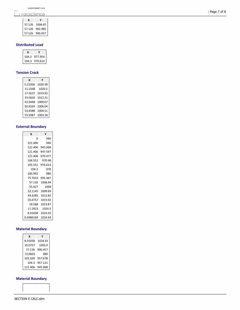
YX
1006.6557.126
992.98557.126
990.45757.126
Distributed Load
YX
977.954104.3
970.614104.3
Tension Crack
YX
1020.385.21056
1020.311.1508
1019.9317.5637
1012.2133.5656
1009.0742.9448
1006.0450.4559
1004.5153.4588
1003.1855.5987
External Boundary
YX
9400
940121.406
945.068121.406
947.597121.406
970.477121.406
970.98106.551
976.614105.551
978104.3
980100.992
995.38775.7033
1006.9457.126
100855.427
1009.6952.1145
1012.8244.3285
1015.9235.0757
1023.8718.588
1024.311.2923
1024.338.91058
1024.440.0486169
Material Boundary
YX
1024.338.91058
1005.935.0757
990.45757.126
98072.0603
957.678103.509
957.121104.3
945.068121.406
Material Boundary
: Page 7 of 8SLIDEINTERPRET 8.018
SECTION E CALC.slim

YX
1023.6313.4967
1008.4235.0757
992.98557.126
982.52972.0603
960.207103.509
959.65104.3
947.597121.406
Material Boundary
YX
1024.311.2923
1023.6313.4967
Material Boundary
YX
950.219104.3
957.121104.3
959.65104.3
978104.3
Material Boundary
YX
978.08157.126
990.45757.126
992.98557.126
1006.9457.126
: Page 8 of 8SLIDEINTERPRET 8.018
SECTION E CALC.slim
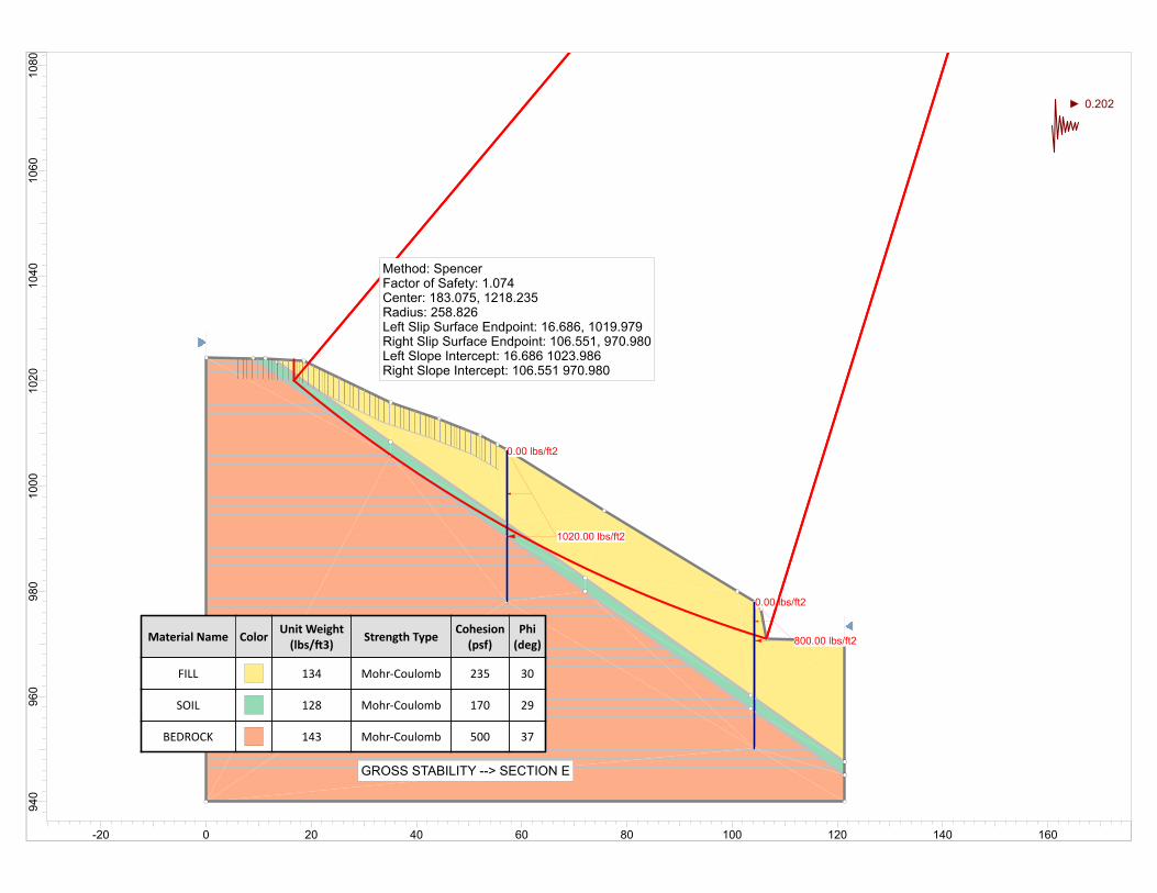
0.00 lbs/ft2
1020.00 lbs/ft2
0.00 lbs/ft2
800.00 lbs/ft2Material Name ColorUnit Weight(lbs/ 3)
Strength TypeCohesion(psf)
Phi(deg)
FILL 134 Mohr‐Coulomb 235 30
SOIL 128 Mohr‐Coulomb 170 29
BEDROCK 143 Mohr‐Coulomb 500 37
GROSS STABILITY --> SECTION E
Method: SpencerFactor of Safety: 1.074Center: 183.075, 1218.235Radius: 258.826Left Slip Surface Endpoint: 16.686, 1019.979Right Slip Surface Endpoint: 106.551, 970.980Left Slope Intercept: 16.686 1023.986Right Slope Intercept: 106.551 970.980
0.202
1080
1060
1040
1020
1000
980
960
940
-20 0 20 40 60 80 100 120 140 160
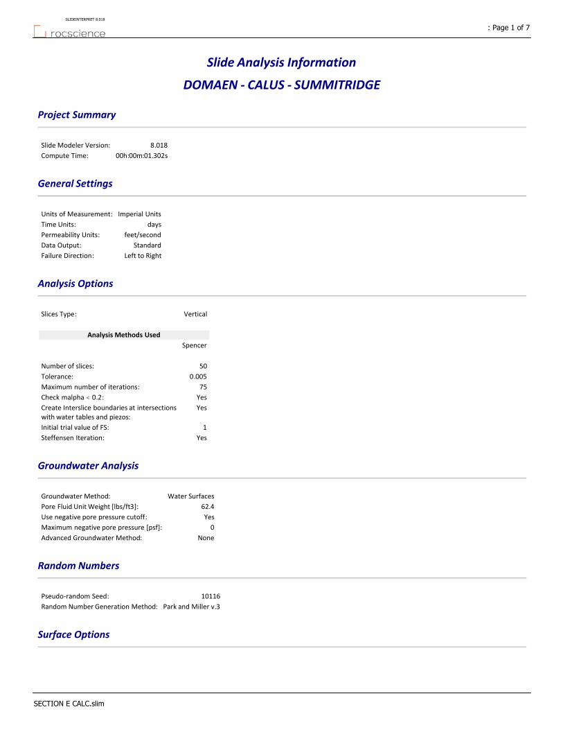
Slide Analysis Information
DOMAEN ‐ CALUS ‐ SUMMITRIDGE
Project Summary
8.018Slide Modeler Version:
00h:00m:01.302sCompute Time:
General Settings
Imperial UnitsUnits of Measurement:
daysTime Units:
feet/secondPermeability Units:
StandardData Output:
Left to RightFailure Direction:
Analysis Options
VerticalSlices Type:
Analysis Methods Used
Spencer
50Number of slices:
0.005Tolerance:
75Maximum number of iterations:
YesCheck malpha < 0.2:YesCreate Interslice boundaries at intersections
with water tables and piezos:
1Initial trial value of FS:
YesSteffensen Iteration:
Groundwater Analysis
Water SurfacesGroundwater Method:
62.4Pore Fluid Unit Weight [lbs/ft3]:
YesUse negative pore pressure cutoff:
0Maximum negative pore pressure [psf]:
NoneAdvanced Groundwater Method:
Random Numbers
10116Pseudo‐random Seed:
Park and Miller v.3Random Number Generation Method:
Surface Options
: Page 1 of 7SLIDEINTERPRET 8.018
SECTION E CALC.slim
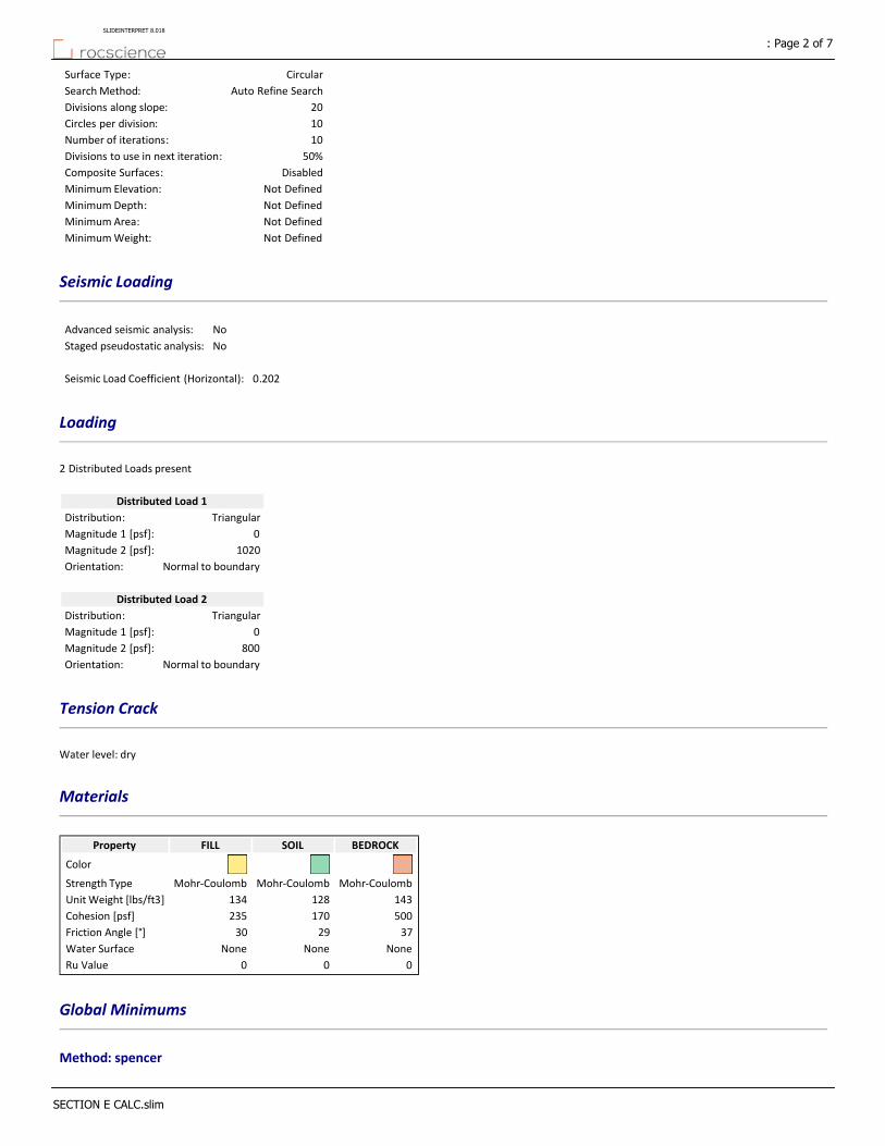
CircularSurface Type:
Auto Refine SearchSearch Method:
20Divisions along slope:
10Circles per division:
10Number of iterations:
50%Divisions to use in next iteration:
DisabledComposite Surfaces:
Not DefinedMinimum Elevation:
Not DefinedMinimum Depth:
Not DefinedMinimum Area:
Not DefinedMinimum Weight:
Seismic Loading
NoAdvanced seismic analysis:
NoStaged pseudostatic analysis:
0.202Seismic Load Coefficient (Horizontal):
Loading
2 Distributed Loads present
Distributed Load 1
TriangularDistribution:
0Magnitude 1 [psf]:
1020Magnitude 2 [psf]:
Normal to boundaryOrientation:
Distributed Load 2
TriangularDistribution:
0Magnitude 1 [psf]:
800Magnitude 2 [psf]:
Normal to boundaryOrientation:
Tension Crack
Water level: dry
Materials
BEDROCKSOILFILLProperty
Color
Mohr‐CoulombMohr‐CoulombMohr‐CoulombStrength Type
143128134Unit Weight [lbs/ft3]
500170235Cohesion [psf]
372930Friction Angle [°]
NoneNoneNoneWater Surface
000Ru Value
Global Minimums
Method: spencer
: Page 2 of 7SLIDEINTERPRET 8.018
SECTION E CALC.slim

1.074060FS
183.075, 1218.235Center:
258.826Radius:
16.686, 1019.979Left Slip Surface Endpoint:
106.551, 970.980Right Slip Surface Endpoint:
16.686 1023.986Left Slope Intercept:
106.551 970.980Right Slope Intercept:
2.11429e+07 lb‐ftResisting Moment:
1.9685e+07 lb‐ftDriving Moment:
72282.6 lbResisting Horizontal Force:
67298.2 lbDriving Horizontal Force:
978.062 ft2Total Slice Area:
89.8654 ftSurface Horizontal Width:
10.8836 ftSurface Average Height:
Valid/Invalid Surfaces
Method: spencer
9501Number of Valid Surfaces:
0Number of Invalid Surfaces:
Slice Data
Global Minimum Query (spencer) ‐ Safety Factor: 1.07406
: Page 3 of 7SLIDEINTERPRET 8.018
SECTION E CALC.slim
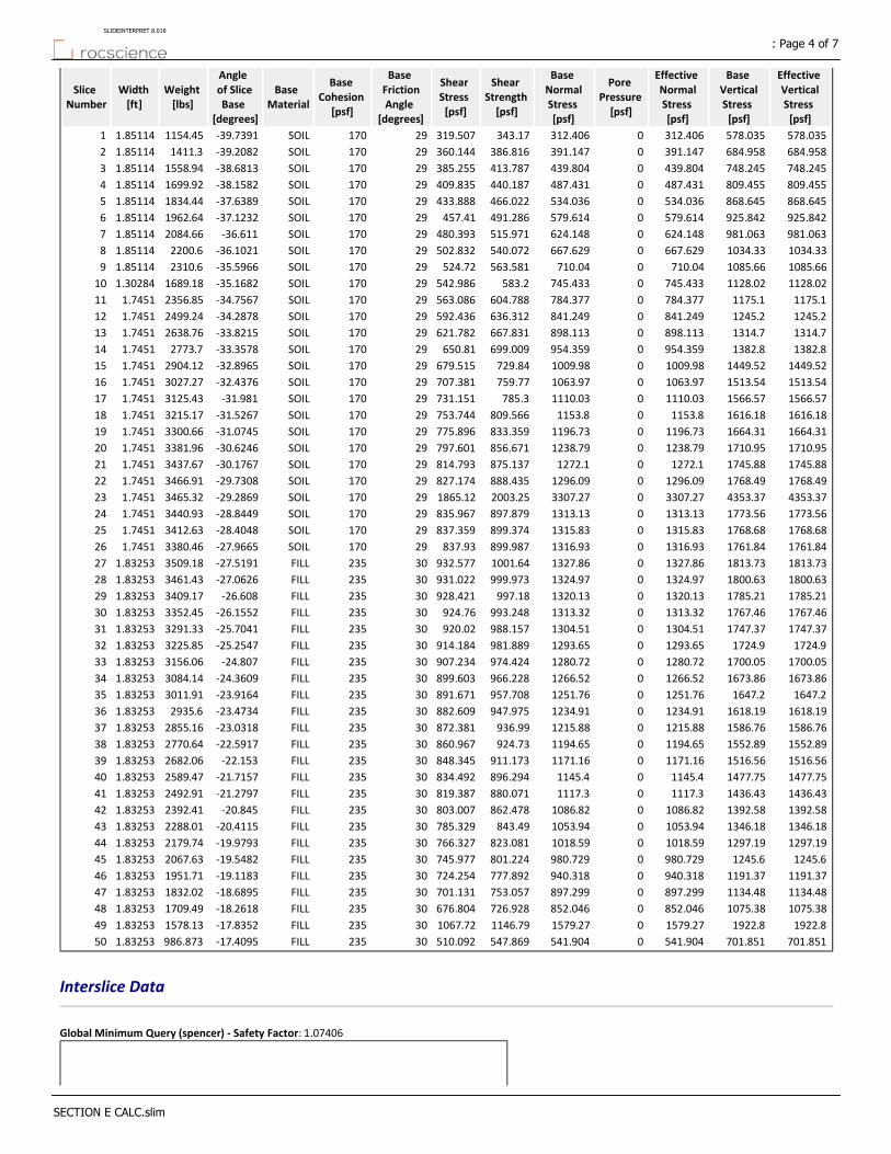
Effective Vertical Stress [psf]
Base Vertical Stress [psf]
Effective Normal Stress [psf]
Pore Pressure [psf]
Base Normal Stress [psf]
Shear Strength [psf]
Shear Stress [psf]
Base Friction Angle
[degrees]
Base Cohesion
[psf]
Base Material
Angle of Slice Base
[degrees]
Weight [lbs]
Width [ft]
Slice Number
578.035578.035312.4060312.406343.17319.50729170SOIL‐39.73911154.451.851141
684.958684.958391.1470391.147386.816360.14429170SOIL‐39.20821411.31.851142
748.245748.245439.8040439.804413.787385.25529170SOIL‐38.68131558.941.851143
809.455809.455487.4310487.431440.187409.83529170SOIL‐38.15821699.921.851144
868.645868.645534.0360534.036466.022433.88829170SOIL‐37.63891834.441.851145
925.842925.842579.6140579.614491.286457.4129170SOIL‐37.12321962.641.851146
981.063981.063624.1480624.148515.971480.39329170SOIL‐36.6112084.661.851147
1034.331034.33667.6290667.629540.072502.83229170SOIL‐36.10212200.61.851148
1085.661085.66710.040710.04563.581524.7229170SOIL‐35.59662310.61.851149
1128.021128.02745.4330745.433583.2542.98629170SOIL‐35.16821689.181.3028410
1175.11175.1784.3770784.377604.788563.08629170SOIL‐34.75672356.851.745111
1245.21245.2841.2490841.249636.312592.43629170SOIL‐34.28782499.241.745112
1314.71314.7898.1130898.113667.831621.78229170SOIL‐33.82152638.761.745113
1382.81382.8954.3590954.359699.009650.8129170SOIL‐33.35782773.71.745114
1449.521449.521009.9801009.98729.84679.51529170SOIL‐32.89652904.121.745115
1513.541513.541063.9701063.97759.77707.38129170SOIL‐32.43763027.271.745116
1566.571566.571110.0301110.03785.3731.15129170SOIL‐31.9813125.431.745117
1616.181616.181153.801153.8809.566753.74429170SOIL‐31.52673215.171.745118
1664.311664.311196.7301196.73833.359775.89629170SOIL‐31.07453300.661.745119
1710.951710.951238.7901238.79856.671797.60129170SOIL‐30.62463381.961.745120
1745.881745.881272.101272.1875.137814.79329170SOIL‐30.17673437.671.745121
1768.491768.491296.0901296.09888.435827.17429170SOIL‐29.73083466.911.745122
4353.374353.373307.2703307.272003.251865.1229170SOIL‐29.28693465.321.745123
1773.561773.561313.1301313.13897.879835.96729170SOIL‐28.84493440.931.745124
1768.681768.681315.8301315.83899.374837.35929170SOIL‐28.40483412.631.745125
1761.841761.841316.9301316.93899.987837.9329170SOIL‐27.96653380.461.745126
1813.731813.731327.8601327.861001.64932.57730235FILL‐27.51913509.181.8325327
1800.631800.631324.9701324.97999.973931.02230235FILL‐27.06263461.431.8325328
1785.211785.211320.1301320.13997.18928.42130235FILL‐26.6083409.171.8325329
1767.461767.461313.3201313.32993.248924.7630235FILL‐26.15523352.451.8325330
1747.371747.371304.5101304.51988.157920.0230235FILL‐25.70413291.331.8325331
1724.91724.91293.6501293.65981.889914.18430235FILL‐25.25473225.851.8325332
1700.051700.051280.7201280.72974.424907.23430235FILL‐24.8073156.061.8325333
1673.861673.861266.5201266.52966.228899.60330235FILL‐24.36093084.141.8325334
1647.21647.21251.7601251.76957.708891.67130235FILL‐23.91643011.911.8325335
1618.191618.191234.9101234.91947.975882.60930235FILL‐23.47342935.61.8325336
1586.761586.761215.8801215.88936.99872.38130235FILL‐23.03182855.161.8325337
1552.891552.891194.6501194.65924.73860.96730235FILL‐22.59172770.641.8325338
1516.561516.561171.1601171.16911.173848.34530235FILL‐22.1532682.061.8325339
1477.751477.751145.401145.4896.294834.49230235FILL‐21.71572589.471.8325340
1436.431436.431117.301117.3880.071819.38730235FILL‐21.27972492.911.8325341
1392.581392.581086.8201086.82862.478803.00730235FILL‐20.8452392.411.8325342
1346.181346.181053.9401053.94843.49785.32930235FILL‐20.41152288.011.8325343
1297.191297.191018.5901018.59823.081766.32730235FILL‐19.97932179.741.8325344
1245.61245.6980.7290980.729801.224745.97730235FILL‐19.54822067.631.8325345
1191.371191.37940.3180940.318777.892724.25430235FILL‐19.11831951.711.8325346
1134.481134.48897.2990897.299753.057701.13130235FILL‐18.68951832.021.8325347
1075.381075.38852.0460852.046726.928676.80430235FILL‐18.26181709.491.8325348
1922.81922.81579.2701579.271146.791067.7230235FILL‐17.83521578.131.8325349
701.851701.851541.9040541.904547.869510.09230235FILL‐17.4095986.8731.8325350
Interslice Data
Global Minimum Query (spencer) ‐ Safety Factor: 1.07406
: Page 4 of 7SLIDEINTERPRET 8.018
SECTION E CALC.slim
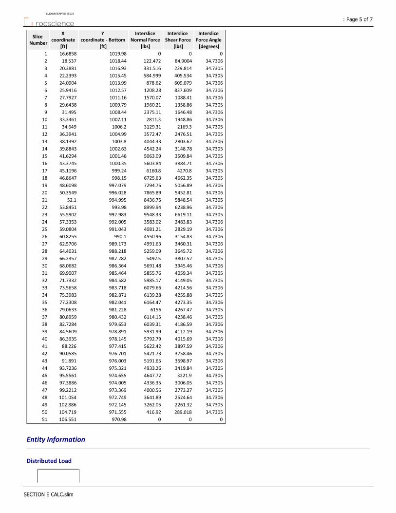
Interslice Force Angle [degrees]
Interslice Shear Force
[lbs]
Interslice Normal Force
[lbs]
Y coordinate ‐ Bottom
[ft]
X coordinate
[ft]
Slice Number
0001019.9816.68581
34.730684.9004122.4721018.4418.5372
34.7305229.814331.5161016.9320.38813
34.7305405.534584.9991015.4522.23934
34.7306609.079878.621013.9924.09045
34.7306837.6091208.281012.5725.94166
34.73061088.411570.071011.1627.79277
34.73051358.861960.211009.7929.64388
34.73061646.482375.111008.4431.4959
34.73061948.862811.31007.1133.346110
34.73052169.33129.311006.234.64911
34.73052476.513572.471004.9936.394112
34.73062803.624044.331003.838.139213
34.73053148.784542.241002.6339.884314
34.73053509.845063.091001.4841.629415
34.73063884.715603.841000.3543.374516
34.73054270.86160.8999.2445.119617
34.73054662.356725.63998.1546.864718
34.73065056.897294.76997.07948.609819
34.73065452.817865.89996.02850.354920
34.73055848.548436.75994.99552.121
34.73066238.968999.94993.9853.845122
34.73056619.119548.33992.98355.590223
34.73062483.833583.02992.00557.335324
34.73062829.194081.21991.04359.080425
34.73063154.834550.96990.160.825526
34.73063460.314991.63989.17362.570627
34.73063645.725259.09988.21864.403128
34.73053807.525492.5987.28266.235729
34.73063945.465691.48986.36468.068230
34.73054059.345855.76985.46469.900731
34.73054149.055985.17984.58271.733232
34.73064214.566079.66983.71873.565833
34.73054255.886139.28982.87175.398334
34.73064273.356164.47982.04177.230835
34.73054267.476156981.22879.063336
34.73054238.466114.15980.43280.895937
34.73064186.596039.31979.65382.728438
34.73064112.195931.99978.89184.560939
34.73064015.695792.79978.14586.393540
34.73063897.595622.42977.41588.22641
34.73053758.465421.73976.70190.058542
34.73063598.975191.65976.00391.89143
34.73053419.844933.26975.32193.723644
34.73053221.94647.72974.65595.556145
34.73053006.054336.35974.00597.388646
34.73052773.274000.56973.36999.221247
34.73062524.643641.89972.749101.05448
34.73052261.323262.05972.145102.88649
34.7305289.018416.92971.555104.71950
000970.98106.55151
Entity Information
Distributed Load
: Page 5 of 7SLIDEINTERPRET 8.018
SECTION E CALC.slim

YX
1006.6557.126
992.98557.126
990.45757.126
Distributed Load
YX
977.954104.3
970.614104.3
Tension Crack
YX
1020.385.21056
1020.311.1508
1019.9317.5637
1012.2133.5656
1009.0742.9448
1006.0450.4559
1004.5153.4588
1003.1855.5987
External Boundary
YX
9400
940121.406
945.068121.406
947.597121.406
970.477121.406
970.98106.551
976.614105.551
978104.3
980100.992
995.38775.7033
1006.9457.126
100855.427
1009.6952.1145
1012.8244.3285
1015.9235.0757
1023.8718.588
1024.311.2923
1024.338.91058
1024.440.0486169
Material Boundary
YX
1024.338.91058
1005.935.0757
990.45757.126
98072.0603
957.678103.509
957.121104.3
945.068121.406
Material Boundary
: Page 6 of 7SLIDEINTERPRET 8.018
SECTION E CALC.slim

YX
1023.6313.4967
1008.4235.0757
992.98557.126
982.52972.0603
960.207103.509
959.65104.3
947.597121.406
Material Boundary
YX
1024.311.2923
1023.6313.4967
Material Boundary
YX
950.219104.3
957.121104.3
959.65104.3
978104.3
Material Boundary
YX
978.08157.126
990.45757.126
992.98557.126
1006.9457.126
: Page 7 of 7SLIDEINTERPRET 8.018
SECTION E CALC.slim
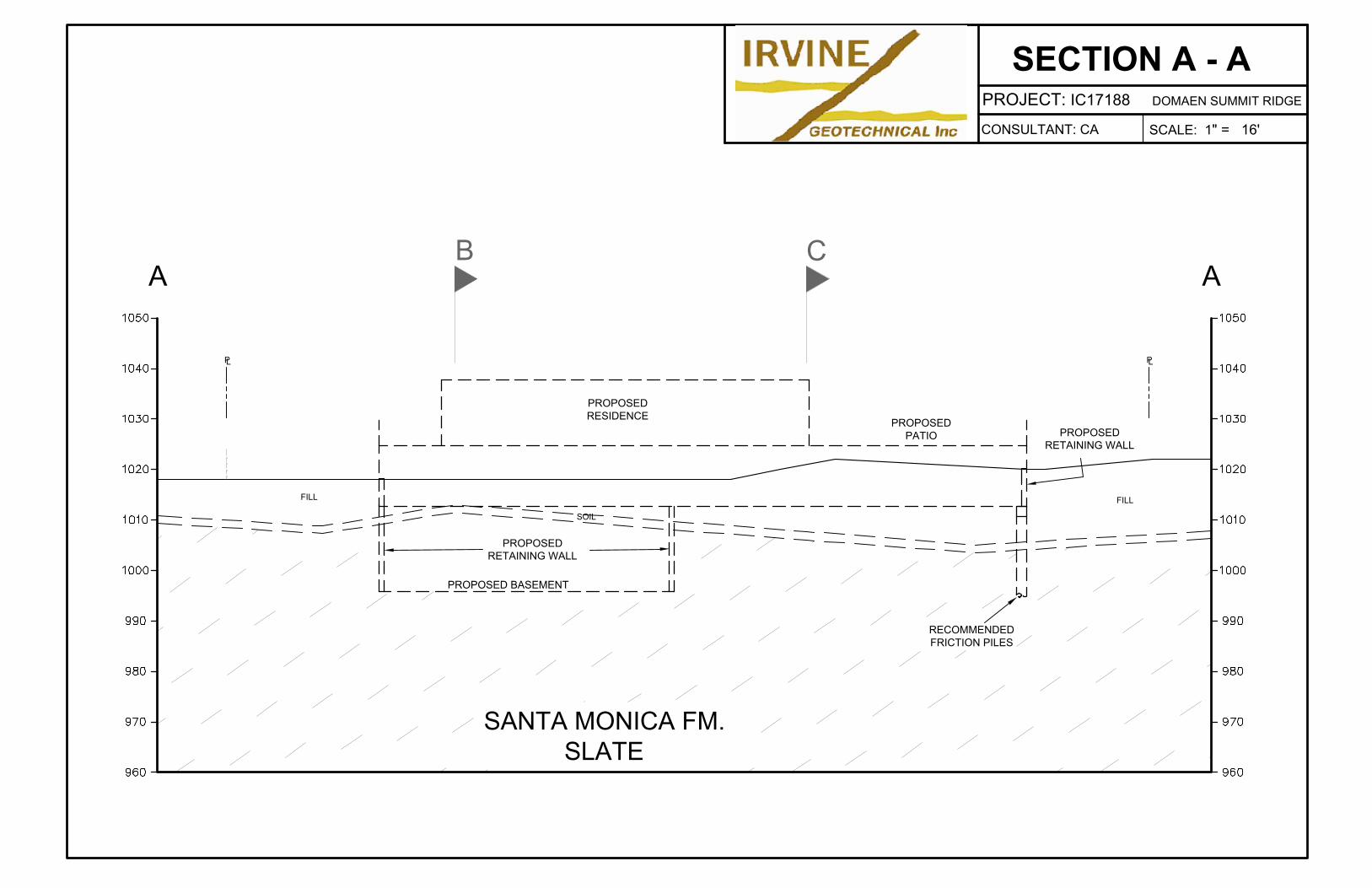
L
P
L
P
PROPOSED
RESIDENCE
FILL
SOIL
A A
PROPOSED
RETAINING WALL
PROPOSED
RETAINING WALL
PROPOSED
PATIO
RECOMMENDED
FRICTION PILES
B C
FILL
SANTA MONICA FM.
SLATE
PROPOSED BASEMENT
SECTION A - A
CONSULTANT: CA
PROJECT: IC17188 DOMAEN SUMMIT RIDGE
SCALE: 1" = 16'
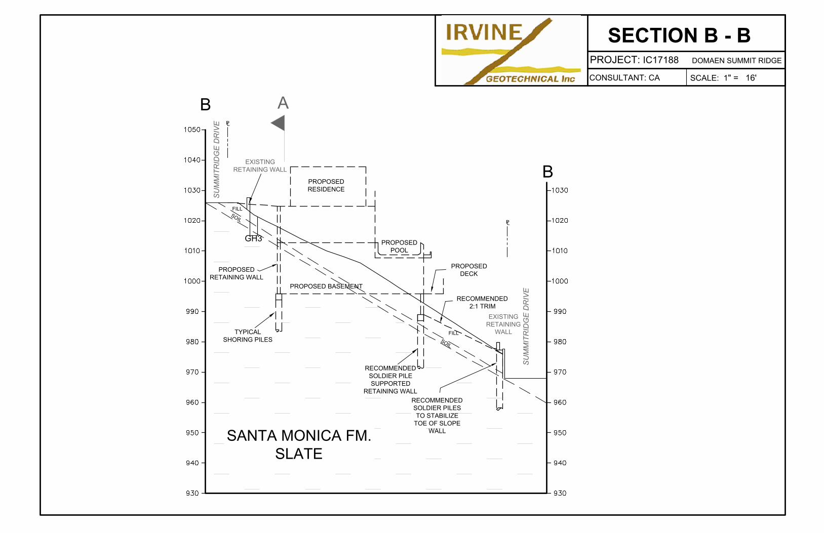
L
P
L
P
PROPOSED
RESIDENCE
S
O
I
L
FILL
B
B
PROPOSED
RETAINING WALL
PROPOSED
POOL
PROPOSED
DECK
TYPICAL
SHORING PILES
EXISTING
RETAINING
WALL
EXISTING
RETAINING WALL
PROPOSED BASEMENT
SU
MM
IT
RID
GE
D
RIV
E
SU
MM
IT
RID
GE
D
RIV
E
RECOMMENDED
SOLDIER PILE
SUPPORTED
RETAINING WALL
GH3
FILL
A
SANTA MONICA FM.
SLATE
RECOMMENDED
2:1 TRIM
S
O
I
L
RECOMMENDED
SOLDIER PILES
TO STABILIZE
TOE OF SLOPE
WALL
SECTION B - B
CONSULTANT: CA
PROJECT: IC17188 DOMAEN SUMMIT RIDGE
SCALE: 1" = 16'
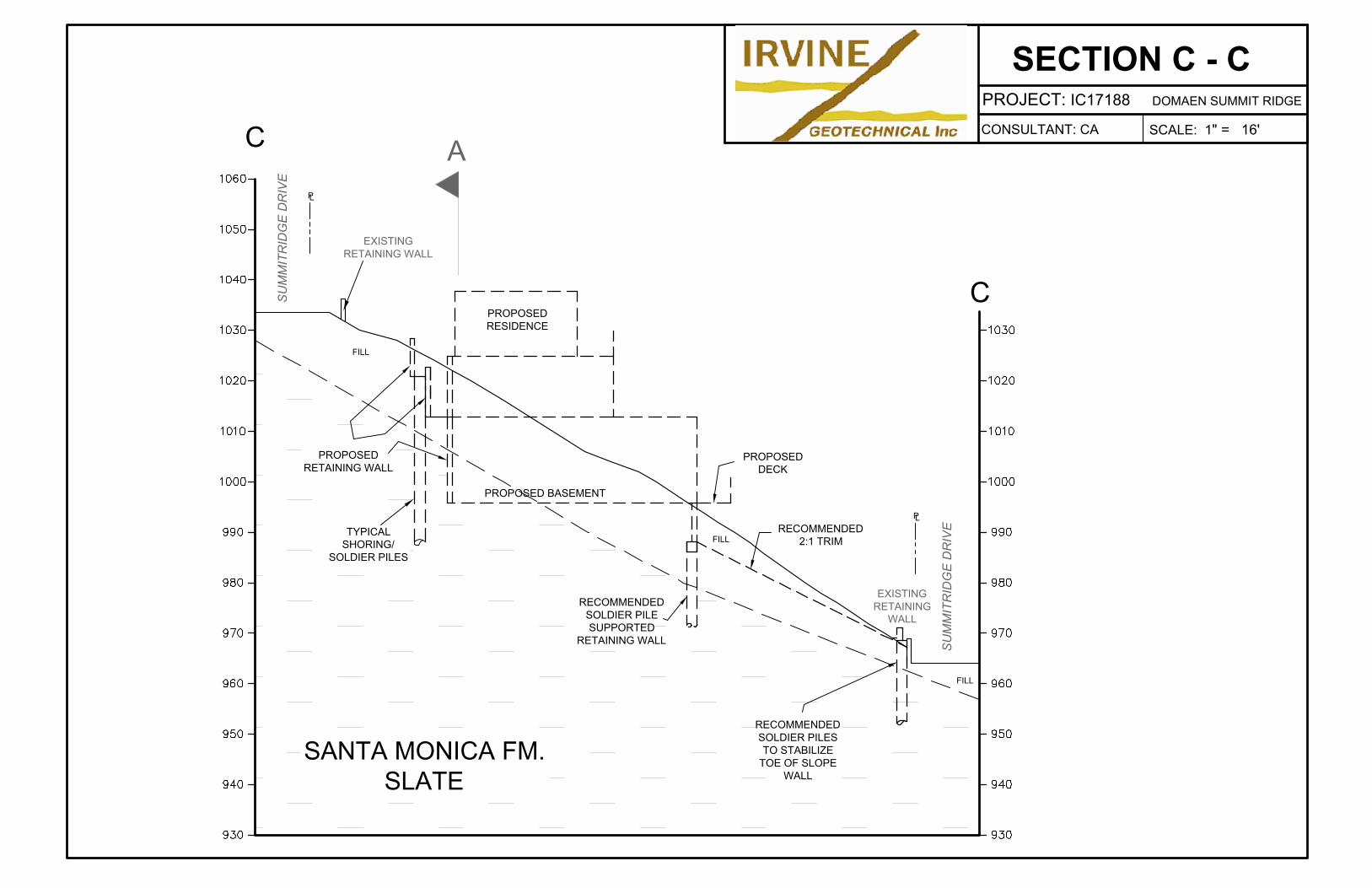
L
P
L
P
PROPOSED
RESIDENCE
FILL
C
C
PROPOSED
DECK
EXISTING
RETAINING
WALL
EXISTING
RETAINING WALL
PROPOSED
RETAINING WALL
PROPOSED BASEMENT
SU
MM
IT
RID
GE
D
RIV
E
SU
MM
IT
RID
GE
D
RIV
E
A
SANTA MONICA FM.
SLATE
TYPICAL
SHORING/
SOLDIER PILES
FILL
FILL
RECOMMENDED
2:1 TRIM
RECOMMENDED
SOLDIER PILE
SUPPORTED
RETAINING WALL
RECOMMENDED
SOLDIER PILES
TO STABILIZE
TOE OF SLOPE
WALL
SECTION C - C
CONSULTANT: CA
PROJECT: IC17188 DOMAEN SUMMIT RIDGE
SCALE: 1" = 16'
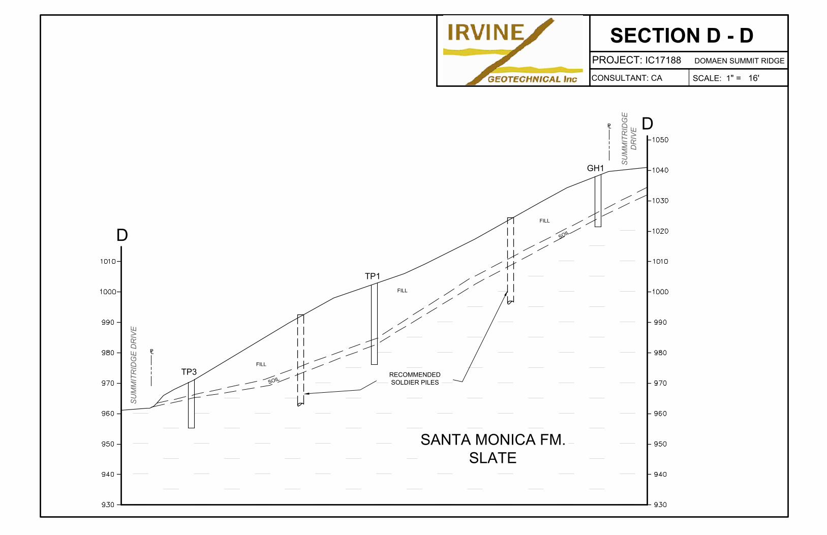
D
D
L
P
L
P
GH1
TP1
TP3
RECOMMENDED
SOLDIER PILES
SU
MM
IT
RID
GE
D
RIV
E
SU
MM
IT
RID
GE
DR
IV
E
FILL
S
O
I
L
S
O
I
L
SANTA MONICA FM.
SLATE
FILL
FILL
SECTION D - D
CONSULTANT: CA
PROJECT: IC17188 DOMAEN SUMMIT RIDGE
SCALE: 1" = 16'
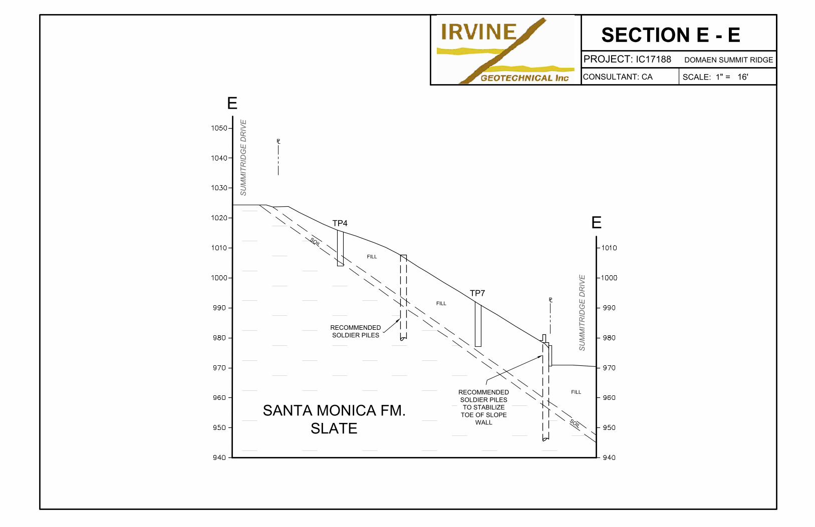
E
SU
MM
IT
RID
GE
D
RIV
E
E
L
P
L
P
TP4
TP7
SU
MM
IT
RID
GE
D
RIV
E
SANTA MONICA FM.
SLATE
S
O
I
L
FILL
S
O
I
L
FILL
FILL
RECOMMENDED
SOLDIER PILES
RECOMMENDED
SOLDIER PILES
TO STABILIZE
TOE OF SLOPE
WALL
SECTION E - E
CONSULTANT: CA
PROJECT: IC17188 DOMAEN SUMMIT RIDGE
SCALE: 1" = 16'
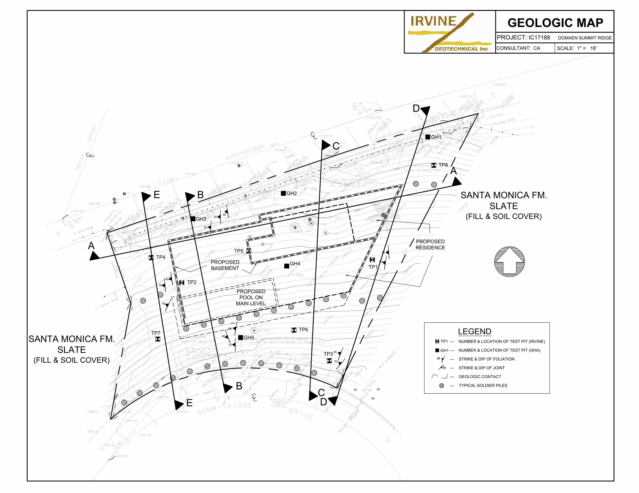
--- NUMBER & LOCATION OF TEST PIT (IRVINE)
--- NUMBER & LOCATION OF TEST PIT (GHA)
--- STRIKE & DIP OF FOLIATION
--- STRIKE & DIP OF JOINT
--- GEOLOGIC CONTACT
--- TYPICAL SOLDIER PILES
LEGEND
TP1
GH1
35
50
45
65
35
GH2
GH5
GH4
TP2
TP1
40
38
A
B
C
B
C
A
TP8
TP5
TP6
TP4
TP7
PROPOSED
RESIDENCE
PROPOSED
POOL ON
MAIN LEVEL
PROPOSED
BASEMENT
45
40
35
20
46
36
40
25
30
GH3
GH1
TP3
E
E
D
D
SANTA MONICA FM.
SLATE
(FILL & SOIL COVER)
SANTA MONICA FM.
SLATE
(FILL & SOIL COVER)
GEOLOGIC MAP
CONSULTANT: CA
PROJECT: IC17188 DOMAEN SUMMIT RIDGE
SCALE: 1" = 16'
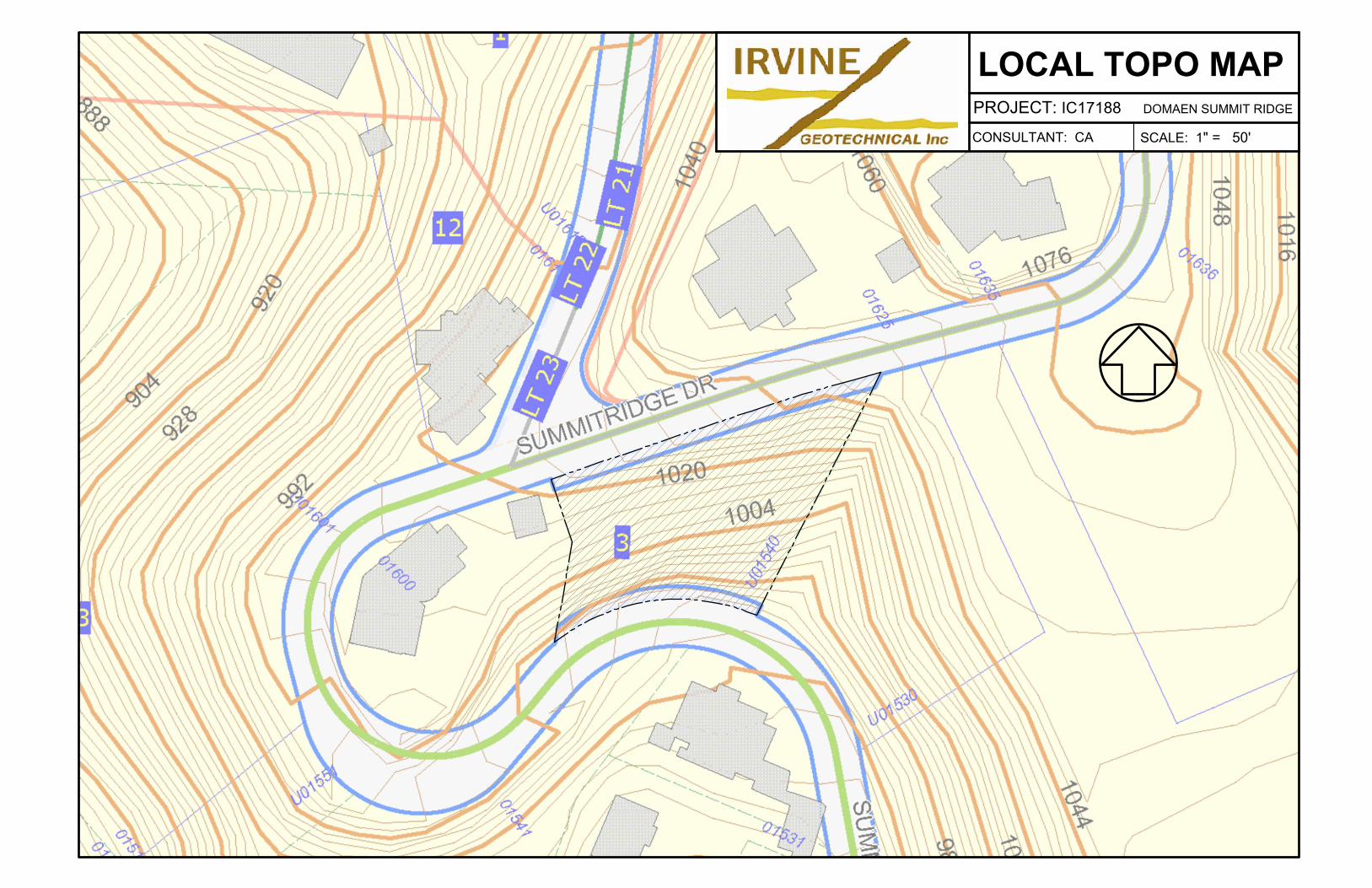
CONSULTANT: CA
PROJECT: IC17188 DOMAEN SUMMIT RIDGE
SCALE: 1" = 50'
LOCAL TOPO MAP