Embed Size (px)
Citation preview
Engineered Infills for Concrete
Barriers
K.A. Snyder (Editor)
Christine Langton Boyd Clark
Chiara Ferraris Jana Dawson
NISTIR 7311
ii
NISTIR 7311
Engineered Infills for Concrete Barriers
K.A. Snyder (Editor) National Institute of Standards and Technology
Christine Langton
Savanna River Site
Boyd Clark R.J. Lee Group
Chiara Ferraris
National Institute of Standards and Technology
Jana Dawson Trinity Engineering
April 2006
U.S. DEPARTMENT OF COMMERCE Carlos M. Gutierrez, Secretary
TECHNOLOGY ADMINISTRATION Michelle O’Neill, Acting Under Secretary of Commerce for Technology
NATIONAL INSTITUTE OF STANDARDS AND TECHNOLOGY William Jeffrey, Director
iii
Table of Contents
1 Introduction .. . . . . . . . . . . . . . . . . . . . . . . . . . . . . . . . . . . . . . . . . . . . . . . . . . . . . . . . . . . . . . . . . . . . . . . . . . . . . . . . . . . . . . .1
1.1 Conceptual Model....................................................................................................... 1 1.2 Definitions.................................................................................................................. 1
1.2.1 Engineered Cementitious Fills (Grouts)...................................................................... 1 1.2.2 Cement/Mortar/Concrete ............................................................................................ 2 1.2.3 Mixtures and Components.......................................................................................... 2 1.2.4 Units .......................................................................................................................... 3
2 Constructability . . . . . . . . . . . . . . . . . . . . . . . . . . . . . . . . . . . . . . . . . . . . . . . . . . . . . . . . . . . . . . . . . . . . . . . . . . . . . . . . . .6 2.1 Introduction ................................................................................................................ 6
2.1.1 Objective.................................................................................................................... 6 2.1.2 Approach.................................................................................................................... 6 2.1.3 Background................................................................................................................ 7
2.2 Entombment/Closure Experience .............................................................................. 12 2.2.1 Nuclear Facility Decommissioning and Closures.......................................................12 2.2.2 Related Construction Experience...............................................................................17
2.3 Reactor Entombment Conceptual Scenarios.............................................................. 17 2.3.1 Spent Fuel Storage Pool Entombment Scenario .........................................................18 2.3.2 Reactor Containment Structure Entombment Scenario...............................................19
2.4 Performance Needs................................................................................................... 20 2.4.1 Approach for Establishing Performance Needs..........................................................20 2.4.2 Approaches to Predicting Long-Term Performance ...................................................31 2.4.3 Time Dependent (Aging) Factors Affecting Performance ..........................................31 2.4.4 Cement – Contaminant Interaction Requirements ......................................................36
2.5 Materials Specification/Selection .............................................................................. 38 2.5.1 Performance Specifications .......................................................................................38 2.5.2 Materials Specifications ............................................................................................39
2.6 Entombment Constructability.................................................................................... 40 2.6.1 Overview...................................................................................................................40 2.6.2 Preconstruction..........................................................................................................41 2.6.3 Design and Engineering.............................................................................................41 2.6.4 Procurement and Construction...................................................................................41 2.6.5 Operation ..................................................................................................................42 2.6.6 Facility Disposal........................................................................................................42
3 Infill and Backfill Rheological Properties . . . . . . . . . . . . . . . . . . . . . . . . . . . . . . . . . . . . . . . . . . . 45 3.1 Introduction .............................................................................................................. 45 3.2 Definitions................................................................................................................ 45
3.2.1 Grout definitions .......................................................................................................45 3.2.2 Rheology...................................................................................................................46 3.2.3 Void filling and the mine case ...................................................................................48
3.3 Materials qualification .............................................................................................. 49 3.3.1 Test methods for performance-based selection...........................................................49 3.3.2 Examples of mixtures................................................................................................52
iv
3.4 Proposed solutions .................................................................................................... 53 3.4.1 Materials available ....................................................................................................53
3.5 Research needs ......................................................................................................... 55 4 Leaching .. . . . . . . . . . . . . . . . . . . . . . . . . . . . . . . . . . . . . . . . . . . . . . . . . . . . . . . . . . . . . . . . . . . . . . . . . . . . . . . . . . . . . . . . . . 56
4.1 Entombment Scenario............................................................................................... 57 4.1.1 Immediate Versus Delayed Entombment...................................................................58 4.1.2 Waste Classification System......................................................................................58 4.1.3 Radionuclide Inventory .............................................................................................59
4.2 Cement Composition ................................................................................................ 61 4.2.1 Cement Paste Formation............................................................................................62 4.2.2 Chemical and Mineralogical Analysis .......................................................................63 4.2.3 Pore-water Chemistry................................................................................................64
4.3 Cement Degradation Processes ................................................................................. 65 4.3.1 Degradation Determination........................................................................................66 4.3.2 Heat Evolution and Thermal Cycling.........................................................................66 4.3.3 Carbonation Reactions...............................................................................................67 4.3.4 Sulfate Attack............................................................................................................69 4.3.5 Radiolysis .................................................................................................................70 4.3.6 Alkali-Aggregate Reactions.......................................................................................70 4.3.7 Microbial-Catalyzed Oxidation Reactions .................................................................71 4.3.8 Degradation by Corrosion..........................................................................................71
4.4 Cement Performance Enhancement........................................................................... 71 4.4.1 Formula Changes ......................................................................................................72
4.5 Cement Performance in Relation To Radionuclide Immobilization ........................... 74 4.5.1 Physical Properties Affecting Grout Performance......................................................74 4.5.2 Chemical Properties Affecting Cement Performance .................................................76 4.5.3 Environmental Influences in Cement Performance ....................................................78 4.5.4 Cement Grout Integrity Assessment ..........................................................................78
4.6 Leaching Tests.......................................................................................................... 79 4.6.1 Diffusion Coefficients and Leach Indices ..................................................................79 4.6.2 Relative Leachability of Select Radionuclides ...........................................................80
4.7 Radionuclide Properties and Leach Characteristics ................................................... 81 4.7.1 137Cs..........................................................................................................................83 4.7.2 55Fe ...........................................................................................................................83 4.7.3 60Co...........................................................................................................................84 4.7.4 152Eu and 154Eu..........................................................................................................84 4.7.5 90Sr............................................................................................................................84 4.7.6 63Ni ...........................................................................................................................85 4.7.7 14C.............................................................................................................................85
4.8 Leaching Studies....................................................................................................... 86 4.8.1 Leaching from Cement Paste.....................................................................................86 4.8.2 Leaching From Cement With Additives...................................................................101
4.9 Additional Research Needs ......................................................................................103 5 Research Needs .. . . . . . . . . . . . . . . . . . . . . . . . . . . . . . . . . . . . . . . . . . . . . . . . . . . . . . . . . . . . . . . . . . . . . . . . . . . . . . 106
5.1 Leaching Data..........................................................................................................106 5.2 Aging Scenarios/Long Term Stability ......................................................................106
v
5.3 Oxidation State ........................................................................................................107 5.4 Surface Complexation Modeling..............................................................................107
6 References . . . . . . . . . . . . . . . . . . . . . . . . . . . . . . . . . . . . . . . . . . . . . . . . . . . . . . . . . . . . . . . . . . . . . . . . . . . . . . . . . . . . . . 109
vi
List of Figures
Figure 1. Schematic drawing of a commercial nuclear power reactor facility........................7 Figure 2. Schematic time line for decommissioning options. ................................................9 Figure 3. Photographs of the Tank 20-F HLW tank closure completed at the SRS in 1997. 14 Figure 4. Simulated debris in Pool 1 filled and covered with stabilization grout..................15 Figure 5. Simulated debris in Pool 2 filled and covered with stabilization grout..................15 Figure 6. Sections of a one-inch PVC vertical pipe (6 m long) filled from the top by gravity
flow with grout. ...........................................................................................................15 Figure 7. One-inch PVC pipe with copper wires (simulated obstructions) filled with grout
pumped through a 1 cm diameter tube. ........................................................................15 Figure 8. Plan view of SRS R-Reactor Fuel Storage Basin scheduled for closure with grout.
Blue color indicates water in the basin. ........................................................................16 Figure 9. Cross section of the SRS R-Reactor Fuel Storage Basin.......................................16 Figure 10. Photograph of the SRS R-Reactor fuel storage pool after infrastructure was
dismantled and dropped into the basin. The water level is shown in the bottom of the photograph. The portion of the basin shown is near the reactor vessel structure at the deep end of the pool.....................................................................................................16
Figure 11. Project Life Cycle of an entombment decommissioning (modified from Ref. 28).....................................................................................................................................43
Figure 12. Relative rates of mineral formation and porosity change with curing time of ordinary Portland cement [73]......................................................................................63
Figure 13. Cumulative Leach Fraction of 137Cs...................................................................94 Figure 14. Cumulative Leach Fraction of 60Co ...................................................................95
vii
List of Tables
Table 1. Comparison of engineered barrier objectives.........................................................11 Table 2. Recommended minimum engineering performance for cementitious fills for reactor
facility decommissioning. ............................................................................................21 Table 3. Recommended minimum performance for shrinkage-compensating cement seals
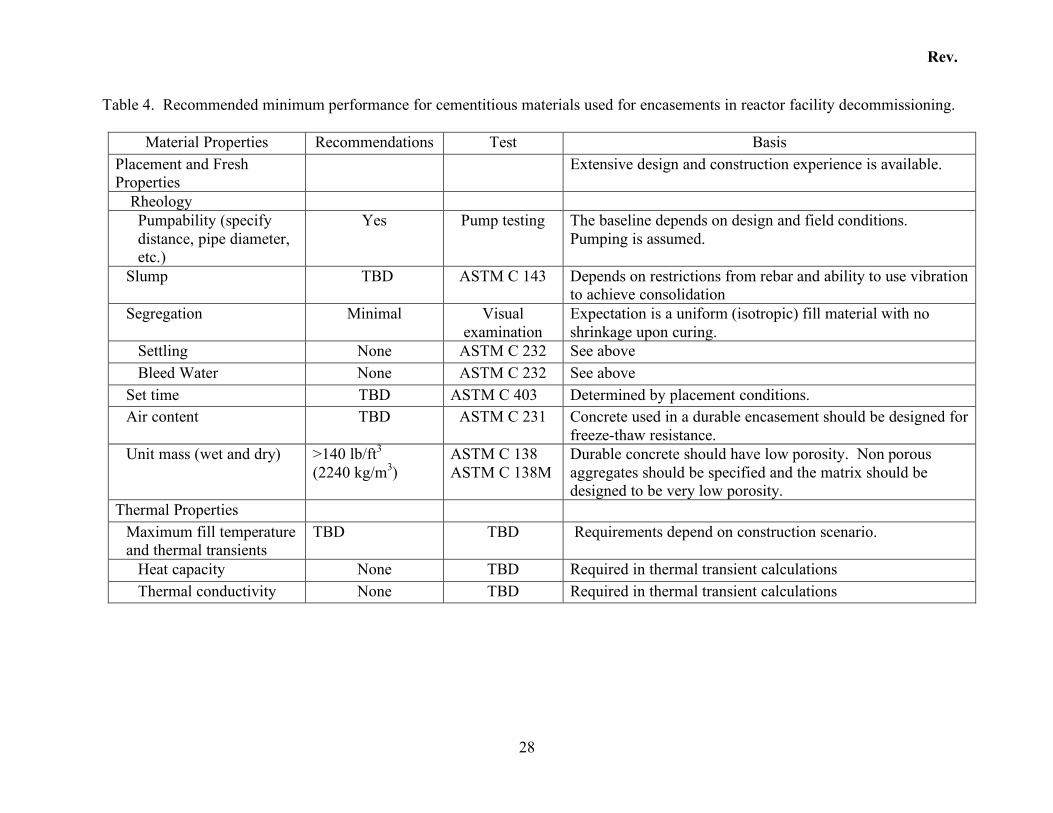
and plugs for reactor facility decommissioning. ...........................................................25 Table 4. Recommended minimum performance for cementitious materials used for
encasements in reactor facility decommissioning. ........................................................28 Table 5. Recommended minimum initial assessment of the effects of aging. ......................34 Table 6. Selected radionuclide data ....................................................................................37 Table 7. Summary of construction experience and constructability issues...........................44 Table 8. Source term half-lives and concentrations of all non-GTCC level wastes in the
Reference PWR [69]....................................................................................................60 Table 9. Portland cement types and Bogue composition [73, 76]. .......................................72 Table 10. Cement additives and matrix modifiers [72]........................................................73 Table 11. Approximate time necessary for capillary pores to no longer percolate the cement
paste microstructure.....................................................................................................76 Table 12. Comparison of diffusion coefficient and retardation factor α of radionuclides
exposed to different leachants [102].............................................................................87 Table 13. Diffusion Coefficients in Cement Waste Forms [107] .........................................89 Table 14. Diffusion coefficients in cement-based waste forms............................................90 Table 15. ANSI 16.1 Leach Test Data for 60Co and 137Cs [108] ..........................................91 Table 16. Composition of Ground Water Leachant. TDS: total dissolved solids. ................91 Table 17. Effective diffusion coefficients of 137Cs and 60Co at different temperatures, Deff in
cm2/day .......................................................................................................................92 Table 18. Leachability Indices 55Fe, 60Co, 63Ni, 90Sr, 137Cs, and 241Pu , ............................100 Table 19. Hydrofracture facility tank sludge test results [110] ..........................................103

viii
1
1 Introduction Entombment may be considered as an option for decommissioning nuclear concrete structures so that licenses for facilities on which these structures reside may be terminated. Prior to entombment, the nuclear facility permanently ceases operations and spent fuel is removed. After preliminary decommissioning activities are completed, some radioactively contaminated components would be left in an existing structure on the site. The radioactive materials are then entombed with an engineered barrier system that could include filling the structure with a grout or infill. Cementitious grouts are a viable candidate for entombment. They can be mechanically stable, and can provide both a physical and a chemical barrier to radionuclide transport. As the concrete structure may be an important barrier to the transport of radionuclides, leaching of radionuclides from both the existing concrete structure and the possible cementitious grout or infill are important parameters for service life performance prediction.
1.1 Conceptual Model
Because each entombment scenario may be unique, a conceptual model for the entombment process is needed to define the limits of the engineering issues of infill/grout selection, formulation, and performance. Here, the conceptual model is based on the objective of completely filling the void space of a nuclear structure. This structure can either be nearly empty, or it may be partially filled with various components from other parts of the facility. The structure will likely have walkways, doors, and various wall penetrations that also need to be completely filled.
1.2 Definitions
Although this work summarizes entombment issues relevant to the performance of cementitious barriers, the variability of cementitious materials that could be used for entombment is vast. A balance is sought between intent and language. To facilitate writing this report, a number of terms are used to describe cement-based materials. These terms should not be construed as limiting or defining the materials that one can consider for entombment.
1.2.1 Engineered Cementitious Fills (Grouts)
Because the term “grout” has a pedestrian meaning related to home maintenance, it carries with it a mental picture to non-technical people that is probably not an accurate representation of the material intended for the entombment of nuclear facilities. The materials that may be used for entombment will have mechanical and chemical properties
2
designed specifically for their application. Because this report is meant to facilitate the use of a number of possible materials for entombment, the reader should not infer a specific material. Moreover, the materials to be used for entombment may require unique characteristics that can only be achieved from a new material. The terms “fill,” “infill,” and “grout” are used here as interchangeable references to any material that can be used to fill the void space within a structure or facility. The distinction among these terms is only a vague reference to the flow properties of each. Fill materials are typically granular, and grouts typically have a liquid component. Neither might have any resemblance to fills and grouts commonly used in civilian construction of non-nuclear facilities. They are very general terms that refer to the mechanical properties of the material, and make no reference to the chemical properties of the material. The overall performance of a particular infill or grout depends upon the choice of materials used in the formulation. This report was written to facilitate material and mixture selection by outlining performance criteria for the material. It is not intended to delineate the boundaries of materials selection and formulation.
1.2.2 Cement/Mortar/Concrete
Because the number of possible materials that could be used for a grout or infill is vast, some means was needed to limit the scope of this report. As such, this report addresses issues that are relevant to the use of cementitious infills/grouts. The term cementitious material refers to any material that has portland cement, as defined by ASTM C 150 [1], as a constituent. The addition of water to cement will form a slurry that will chemically react to form a hardened cement paste; in the following sections, the term “cement paste” is used to represent “hardened cement paste microstructure.” It is common to make composite materials with cement. The combination of cement, water, and fine aggregate is a mortar that, with proper formulation and aggregate selection, can also act as a grouting material. The addition of large aggregates to a mortar is referred to as concrete. The advantages of using aggregates are lower total heat production (from the chemical hydration reaction of the cement and water) and lower total shrinkage, which reduces the likelihood of cracking. Cementitious materials are not limited to cement, water, and aggregates. One could also add any number of supplemental materials such as fly ash, fumed silica, and blast furnace slag. Each supplemental material has advantages and disadvantages that one should be aware of when formulating the infill/grout. Moreover, there are a number of chemical admixtures that can be used to achieve desired material characteristics of the fresh and/or hardened material.
1.2.3 Mixtures and Components
It should be stressed that although a number of supplemental admixtures exist, and that these materials can be used to achieve highly desirable properties, they should not be
3
viewed as “magic bullets” for infill/grout formulation. Cementitious materials such as cement and concrete are commodity products that are produced from natural materials. As such, there is material variability, both between producers and even within a single cement or concrete production facility. As such, care should be used in the formulation of cementitious materials that have narrow acceptance limits on performance.
1.2.4 Units
In many cases, standard engineering practice stipulates performance criteria that are stated in English units of inches (in), feet (ft), pounds (lb), cubic yards (yd3), and pounds (force) per square inch (psi). For these performance criteria, the units are given first, followed by the nominal value in SI units.
4
LIST OF ACRONYMS ALARA As Low As Reasonably Achievable
ANSI American National Standards Institute
ASTM ASTM International
BDAT Best Developed Available Technology
BONUS BOiling NUclear Superheater
BWR Boiling Water Reactor
CERCLA Comprehensive Environmental Response, Compensation, and Liability Act
CFR Code of Federal Regulations
CII Construction Industry Institute
DECON Decontamination Decommissioning
DOD U. S. Department of Defense
DOE U. S. Department of Energy
ENTOMB Entombment Decommissioning
EPA Environmental Protection Agency
GAAT Gunite and Associated Tanks
GTCC Greater Than Class C
HLW High-Level Waste
HRWRA High-Range Water Reducing Admixture
INEEL Idaho National Engineering and Environmental Laboratory
IRPC Indian Red Pottery Clay
IAEA International Atomic Energy Association
ISO International Organization for Standardization
LLW Low-Level Waste
LWR Light Water Reactor
NIST National Institute of Standards and Technology
NRC Nuclear Regulatory Commission
ORNL Oak Ridge National Laboratory
PCB polychlorinated biphenyls
PWR Pressurized Water Reactor
5
RCRA Resource Conservation and Recovery Act
SAFSTOR Safe Storage Decommissioning
SECY Secretary of the Commission, Office of the (NRC)
SOW Statement of Work
SRG Savannah River Reducing Grout
SRS Savannah River Site
SRNL Savannah River National Laboratory
TBD To Be Determined
TEDE Total Effective Dose Equivalent
TSCA Toxic Substance Control Act
TRU Transuranic
US NRC United States Nuclear Regulatory Commission
VLTS Very Long Time Scales
VMA Viscosity modifying admixture
WSRC Westinghouse Savannah River Company, LLC
XRD X-Ray Diffraction
6
2 Constructability
2.1 Introduction
All facilities within the nuclear fuel cycle will eventually need to be decommissioned following their permanent closure. These facilities include uranium mines, ore processing and refining facilities, conversion facilities, enrichment plants, fuel fabrication plants, reactors, reprocessing plants, waste treatment facilities, and waste disposal facilities. Constructability of a decommissioning entombment requires a clear understanding of the scope of the project and the performance of the structure to be constructed. To a large extent, constructability is influenced by the degree to which the designer can engineer the elements/components required and specify the properties of the materials used. Additional aspects of addressing constructability include the ability to:
1. Determine whether the project was constructed as designed 2. Perform material quality control and assurance testing 3. Monitor performance throughout the design life
2.1.1 Objective
The objective of this report is to provide an assessment of the difficulties and issues involved in using cementitious materials to entomb a commercial nuclear power reactor facility. The following issues are discussed:
• Material selection and specification • Property evaluation/measurement/testing • Constructability
2.1.2 Approach
The approach used to meet the objectives was to summarize background information on nuclear facilities and the nuclear facility entombment concept. Activities associated with commercial nuclear facility entombment scenarios were identified. Components of an entombment that may be constructed of cement-based materials were identified, and material property requirements were evaluated for each element. Constructability of entombments was based on experience in closing DOE high-level waste tanks and other related experience. In the United States, nuclear reactor facilities include: commercial power reactors, research reactors, and demonstration reactors licensed for operation by the NRC, small DOD power reactors (primarily naval reactors) and DOE isotope production reactors (no longer operating). This review is focused on entombment of commercial power reactor facilities but draws on
7
entombment/closure experience of other types of nuclear facilities primarily in the DOE complex.
2.1.3 Background
2.1.3.1 Nuclear Reactor Facility Structures
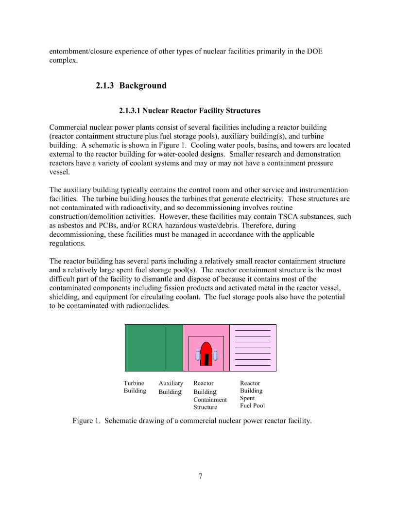
Commercial nuclear power plants consist of several facilities including a reactor building (reactor containment structure plus fuel storage pools), auxiliary building(s), and turbine building. A schematic is shown in Figure 1. Cooling water pools, basins, and towers are located external to the reactor building for water-cooled designs. Smaller research and demonstration reactors have a variety of coolant systems and may or may not have a containment pressure vessel. The auxiliary building typically contains the control room and other service and instrumentation facilities. The turbine building houses the turbines that generate electricity. These structures are not contaminated with radioactivity, and so decommissioning involves routine construction/demolition activities. However, these facilities may contain TSCA substances, such as asbestos and PCBs, and/or RCRA hazardous waste/debris. Therefore, during decommissioning, these facilities must be managed in accordance with the applicable regulations. The reactor building has several parts including a relatively small reactor containment structure and a relatively large spent fuel storage pool(s). The reactor containment structure is the most difficult part of the facility to dismantle and dispose of because it contains most of the contaminated components including fission products and activated metal in the reactor vessel, shielding, and equipment for circulating coolant. The fuel storage pools also have the potential to be contaminated with radionuclides.
Figure 1. Schematic drawing of a commercial nuclear power reactor facility.
Turbine Building
Auxiliary Building
Reactor Building Containment Structure
Reactor Building Spent Fuel Pool
8
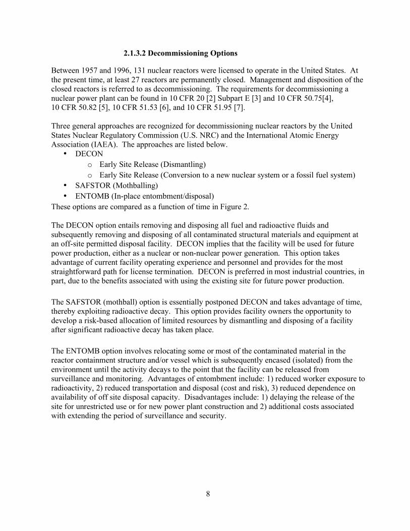
2.1.3.2 Decommissioning Options
Between 1957 and 1996, 131 nuclear reactors were licensed to operate in the United States. At the present time, at least 27 reactors are permanently closed. Management and disposition of the closed reactors is referred to as decommissioning. The requirements for decommissioning a nuclear power plant can be found in 10 CFR 20 [2] Subpart E [3] and 10 CFR 50.75[4], 10 CFR 50.82 [5], 10 CFR 51.53 [6], and 10 CFR 51.95 [7]. Three general approaches are recognized for decommissioning nuclear reactors by the United States Nuclear Regulatory Commission (U.S. NRC) and the International Atomic Energy Association (IAEA). The approaches are listed below.
• DECON o Early Site Release (Dismantling) o Early Site Release (Conversion to a new nuclear system or a fossil fuel system)
• SAFSTOR (Mothballing) • ENTOMB (In-place entombment/disposal)
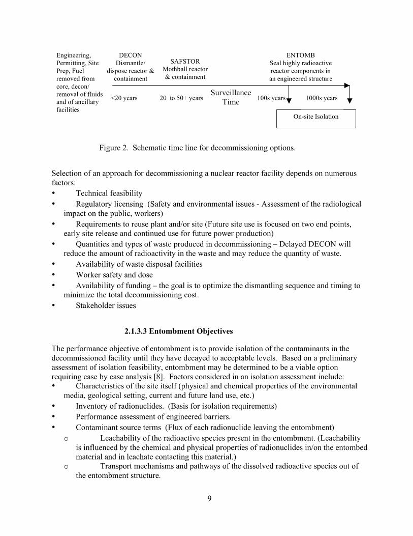
These options are compared as a function of time in Figure 2. The DECON option entails removing and disposing all fuel and radioactive fluids and subsequently removing and disposing of all contaminated structural materials and equipment at an off-site permitted disposal facility. DECON implies that the facility will be used for future power production, either as a nuclear or non-nuclear power generation. This option takes advantage of current facility operating experience and personnel and provides for the most straightforward path for license termination. DECON is preferred in most industrial countries, in part, due to the benefits associated with using the existing site for future power production. The SAFSTOR (mothball) option is essentially postponed DECON and takes advantage of time, thereby exploiting radioactive decay. This option provides facility owners the opportunity to develop a risk-based allocation of limited resources by dismantling and disposing of a facility after significant radioactive decay has taken place. The ENTOMB option involves relocating some or most of the contaminated material in the reactor containment structure and/or vessel which is subsequently encased (isolated) from the environment until the activity decays to the point that the facility can be released from surveillance and monitoring. Advantages of entombment include: 1) reduced worker exposure to radioactivity, 2) reduced transportation and disposal (cost and risk), 3) reduced dependence on availability of off site disposal capacity. Disadvantages include: 1) delaying the release of the site for unrestricted use or for new power plant construction and 2) additional costs associated with extending the period of surveillance and security.
9
Figure 2. Schematic time line for decommissioning options.
Selection of an approach for decommissioning a nuclear reactor facility depends on numerous factors: • Technical feasibility • Regulatory licensing (Safety and environmental issues - Assessment of the radiological
impact on the public, workers) • Requirements to reuse plant and/or site (Future site use is focused on two end points,
early site release and continued use for future power production) • Quantities and types of waste produced in decommissioning – Delayed DECON will
reduce the amount of radioactivity in the waste and may reduce the quantity of waste. • Availability of waste disposal facilities • Worker safety and dose • Availability of funding – the goal is to optimize the dismantling sequence and timing to
minimize the total decommissioning cost. • Stakeholder issues
2.1.3.3 Entombment Objectives
The performance objective of entombment is to provide isolation of the contaminants in the decommissioned facility until they have decayed to acceptable levels. Based on a preliminary assessment of isolation feasibility, entombment may be determined to be a viable option requiring case by case analysis [8]. Factors considered in an isolation assessment include: • Characteristics of the site itself (physical and chemical properties of the environmental
media, geological setting, current and future land use, etc.) • Inventory of radionuclides. (Basis for isolation requirements) • Performance assessment of engineered barriers. • Contaminant source terms (Flux of each radionuclide leaving the entombment)
o Leachability of the radioactive species present in the entombment. (Leachability is influenced by the chemical and physical properties of radionuclides in/on the entombed material and in leachate contacting this material.)
o Transport mechanisms and pathways of the dissolved radioactive species out of the entombment structure.
ENTOMB Seal highly radioactive reactor components in an engineered structure
DECON Dismantle/
dispose reactor & containment
Engineering, Permitting, Site Prep, Fuel removed from core, decon/ removal of fluids and of ancillary facilities
SAFSTOR Mothball reactor & containment
Surveillance Time <20 years 20 to 50+ years 100s years
On-site Isolation
1000s years
10
o Dispersal pathways of contaminants into the environment outside beyond the entombed structure via ground water pathways, plant uptakes, inadvertent intrusion or other scenarios.
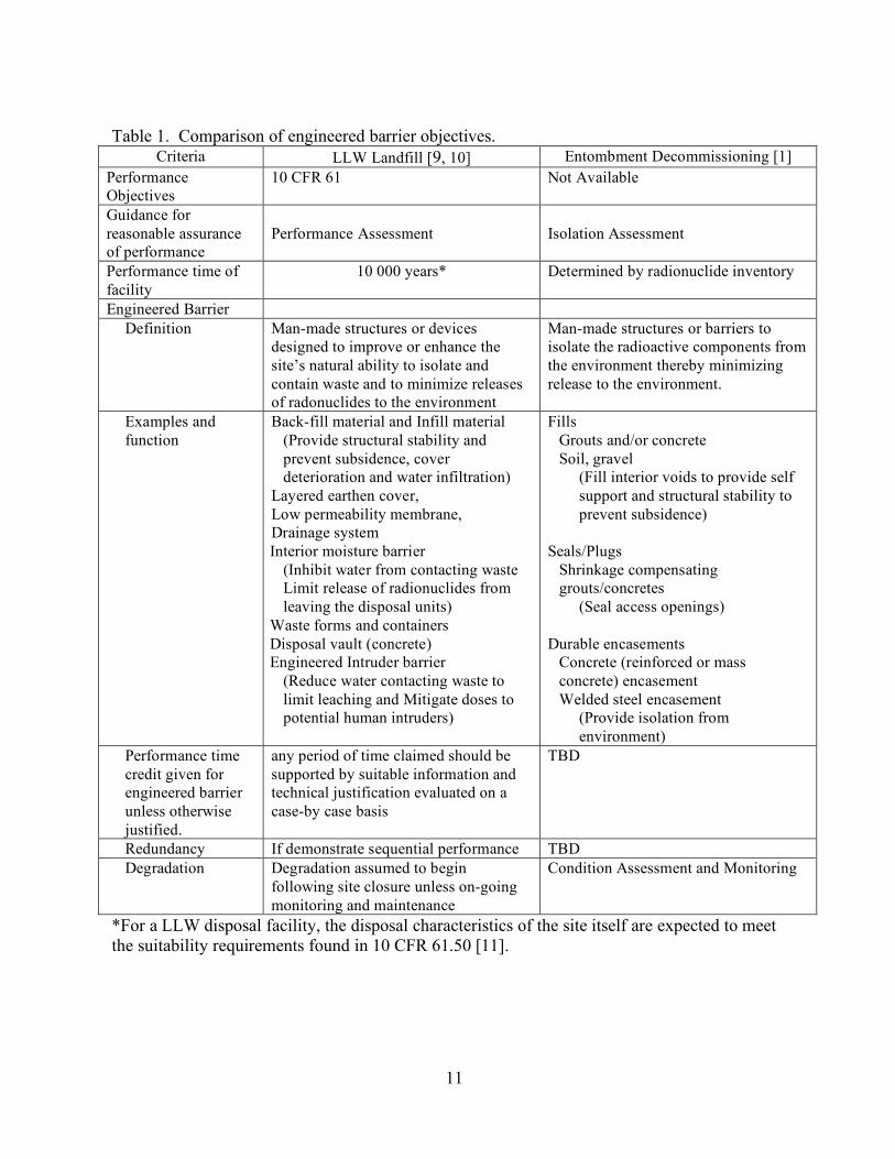
To date regulations have not been promulgated for entombment decommissionings. However, it is useful to compare entombment logic with the objectives and guidance available for engineered barriers used in LLW disposal facilities. A comparison of engineered barrier objectives is given in Table 1 below.
11
Table 1. Comparison of engineered barrier objectives.
Criteria LLW Landfill [9, 10] Entombment Decommissioning [1] Performance Objectives
10 CFR 61 Not Available
Guidance for reasonable assurance of performance
Performance Assessment
Isolation Assessment
Performance time of facility
10 000 years* Determined by radionuclide inventory
Engineered Barrier Definition Man-made structures or devices
designed to improve or enhance the site’s natural ability to isolate and contain waste and to minimize releases of radonuclides to the environment
Man-made structures or barriers to isolate the radioactive components from the environment thereby minimizing release to the environment.
Examples and function
Back-fill material and Infill material (Provide structural stability and prevent subsidence, cover deterioration and water infiltration)
Layered earthen cover, Low permeability membrane, Drainage system Interior moisture barrier
(Inhibit water from contacting waste Limit release of radionuclides from leaving the disposal units)
Waste forms and containers Disposal vault (concrete) Engineered Intruder barrier
(Reduce water contacting waste to limit leaching and Mitigate doses to potential human intruders)
Fills Grouts and/or concrete Soil, gravel
(Fill interior voids to provide self support and structural stability to prevent subsidence)
Seals/Plugs Shrinkage compensating grouts/concretes
(Seal access openings)
Durable encasements Concrete (reinforced or mass concrete) encasement Welded steel encasement
(Provide isolation from environment)
Performance time credit given for engineered barrier unless otherwise justified.
any period of time claimed should be supported by suitable information and technical justification evaluated on a case-by case basis
TBD
Redundancy If demonstrate sequential performance TBD Degradation Degradation assumed to begin
following site closure unless on-going monitoring and maintenance
Condition Assessment and Monitoring
*For a LLW disposal facility, the disposal characteristics of the site itself are expected to meet the suitability requirements found in 10 CFR 61.50 [11].
12
2.2 Entombment/Closure Experience
2.2.1 Nuclear Facility Decommissioning and Closures
2.2.1.1 Reactor Entombments
To date, three small reactors have been entombed in the US and Puerto Rico, and experience in the United States has been summarized [12]. Brief descriptions are provided here for completeness. The Hallam Nuclear Power Facility, Hallam NE, was a 240 MW thermal sodium–cooled, graphite-moderated demonstration reactor, which was built and operated by the USAEC between 1962 and 1966. In 1967 the Nebraska Public Power District was authorized to decommission and dismantle the facility. All of the nuclear waste was removed from the reactor and disposed of off-site. The remaining radioactive materials were sealed in underground vaults at the plant site. In 1969, the reactor was sealed underneath two welded steel plates and buried under an engineered cap consisting of a synthetic liner, tar, and earth. To date, no surface radiation or ground water contamination has been detected. The Piqua Nuclear Power Facility, Piqua OH, was another federal demonstration plant. It contained a 45.5 MW thermal organically cooled and moderated reactor that was built and operated between 1963 and 1966. The facility was decommissioned and dismantled between 1967 and 1969. The reactor fuel, coolant, and most of the radioactive materials were removed from the reactor before it was sealed. The reactor vessel and space around the reactor were filled with dry quartz sand. After decontamination, the reactor building became a warehouse. No radiation releases have been detected. The Boiling Nuclear Superheater (BONUS) power station was also a demonstration plant operated from 1964 to 1967 in Rincon, Puerto Rico. The nuclear waste generated as the result of operating the reactor was removed and disposed of off-site. The reactor was sealed within a concrete slab. On-site disposal was completed in 1970.
2.2.1.2 Processing Facility Entombments
The Old Cave Facility at the Mound Plant (Miamisburg, OH) has been described as an example of an entombed facility. However, in the context of this discussion, it is an example of the SAFSTOR option rather than an entombment since the facility is currently being removed as part of the DOE site remediation effort. This facility was constructed in the early 1950s and occupied an area of approximately 90 m2 in the Semi-Works Building. The facility was used to process radium (226Ra) and actinium (227Ac) from 1951 to 1955. Some of the items buried within the entombment structure include: a crane and crane rail, cave shielding doors, end shield plates, manipulator units, refrigeration unit, etc. The entombment structure consisted of a concrete encasement.
13
2.2.1.3 HLW Tank Closures
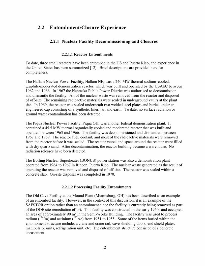
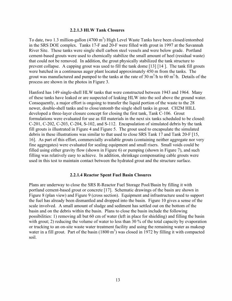
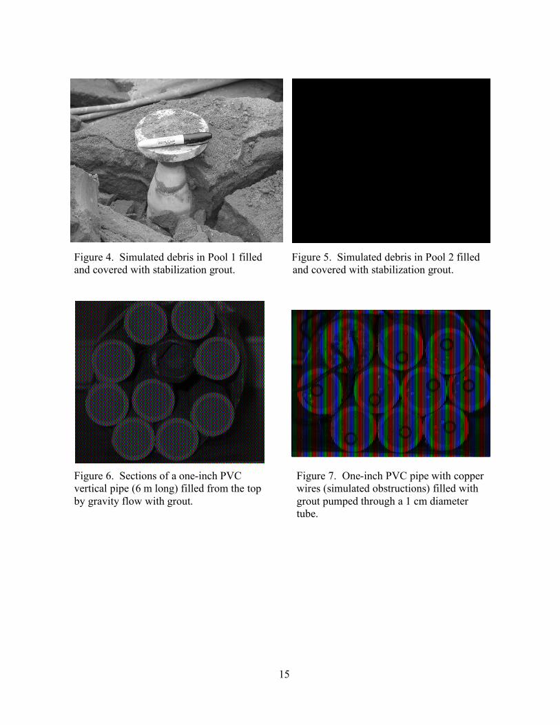
To date, two 1.3 million-gallon (4700 m3) High Level Waste Tanks have been closed/entombed in the SRS DOE complex. Tanks 17-F and 20-F were filled with grout in 1997 at the Savannah River Site. These tanks were single shell carbon steel vessels and were below grade. Portland cement-based grouts were used to chemically stabilize the small amount of heel (residual waste) that could not be removed. In addition, the grout physically stabilized the tank structure to prevent collapse. A capping grout was used to fill the tank dome [13] [14 ]. The tank fill grouts were batched in a continuous auger plant located approximately 450 m from the tanks. The grout was manufactured and pumped to the tanks at the rate of 30 m3/h to 60 m3/h. Details of the process are shown in the photos in Figure 3. Hanford has 149 single-shell HLW tanks that were constructed between 1943 and 1964. Many of these tanks have leaked or are suspected of leaking HLW into the soil above the ground water. Consequently, a major effort is ongoing to transfer the liquid portion of the waste to the 28 newer, double-shell tanks and to close/entomb the single shell tanks in grout. CH2M HILL developed a three-layer closure concept for closing the first tank, Tank C-106. Grout formulations were evaluated for use as fill materials in the next six tanks scheduled to be closed: C-201, C-202, C-203, C-204, S-102, and S-112. Encapsulation of simulated debris by the tank fill grouts is illustrated in Figure 4 and Figure 5. The grout used to encapsulate the simulated debris in these illustrations was similar to that used to close SRS Tank 17 and Tank 20-F [15, 16]. As part of this effort, commercially available grouts (containing neither aggregate nor very fine aggregates) were evaluated for sealing equipment and small risers. Small voids could be filled using either gravity flow (shown in Figure 6) or pumping (shown in Figure 7), and such filling was relatively easy to achieve. In addition, shrinkage compensating cable grouts were used in this test to maintain contact between the hydrated grout and the structure surface.
2.2.1.4 Reactor Spent Fuel Basin Closures
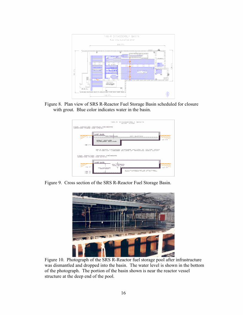
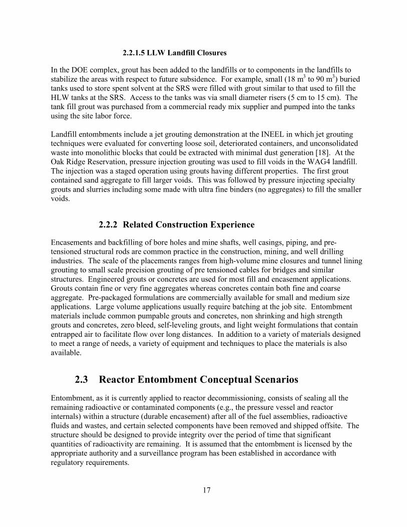
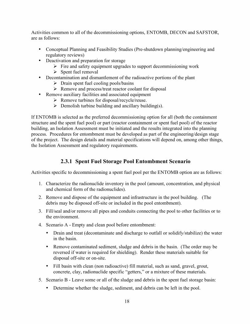
Plans are underway to close the SRS R-Reactor Fuel Storage Pool/Basin by filling it with portland cement-based grout or concrete [17]. Schematic drawings of the basin are shown in Figure 8 (plan view) and Figure 9 (cross section). Equipment and infrastructure used to support the fuel has already been dismantled and dropped into the basin. Figure 10 gives a sense of the scale involved. A small amount of sludge and sediment has settled out on the bottom of the basin and on the debris within the basin. Plans to close the basin include the following possibilities: 1) removing all but 60 cm of water (left in place for shielding) and filling the basin with grout; 2) reducing the volume of water to less than 30 % of the total capacity by evaporation or trucking to an on-site waste water treatment facility and using the remaining water as makeup water in a fill grout. Part of the basin (1800 m3) was closed in 1972 by filling it with compacted soil.
14
Figure 3. Photographs of the Tank 20-F HLW tank closure completed at the SRS in 1997.
15
Figure 4. Simulated debris in Pool 1 filled and covered with stabilization grout.
Figure 5. Simulated debris in Pool 2 filled and covered with stabilization grout.
Figure 6. Sections of a one-inch PVC vertical pipe (6 m long) filled from the top by gravity flow with grout.
Figure 7. One-inch PVC pipe with copper wires (simulated obstructions) filled with grout pumped through a 1 cm diameter tube.
16
Figure 8. Plan view of SRS R-Reactor Fuel Storage Basin scheduled for closure
with grout. Blue color indicates water in the basin.
Figure 9. Cross section of the SRS R-Reactor Fuel Storage Basin.
Figure 10. Photograph of the SRS R-Reactor fuel storage pool after infrastructure was dismantled and dropped into the basin. The water level is shown in the bottom of the photograph. The portion of the basin shown is near the reactor vessel structure at the deep end of the pool.
17
2.2.1.5 LLW Landfill Closures
In the DOE complex, grout has been added to the landfills or to components in the landfills to stabilize the areas with respect to future subsidence. For example, small (18 m3 to 90 m3) buried tanks used to store spent solvent at the SRS were filled with grout similar to that used to fill the HLW tanks at the SRS. Access to the tanks was via small diameter risers (5 cm to 15 cm). The tank fill grout was purchased from a commercial ready mix supplier and pumped into the tanks using the site labor force. Landfill entombments include a jet grouting demonstration at the INEEL in which jet grouting techniques were evaluated for converting loose soil, deteriorated containers, and unconsolidated waste into monolithic blocks that could be extracted with minimal dust generation [18]. At the Oak Ridge Reservation, pressure injection grouting was used to fill voids in the WAG4 landfill. The injection was a staged operation using grouts having different properties. The first grout contained sand aggregate to fill larger voids. This was followed by pressure injecting specialty grouts and slurries including some made with ultra fine binders (no aggregates) to fill the smaller voids.
2.2.2 Related Construction Experience
Encasements and backfilling of bore holes and mine shafts, well casings, piping, and pre-tensioned structural rods are common practice in the construction, mining, and well drilling industries. The scale of the placements ranges from high-volume mine closures and tunnel lining grouting to small scale precision grouting of pre tensioned cables for bridges and similar structures. Engineered grouts or concretes are used for most fill and encasement applications. Grouts contain fine or very fine aggregates whereas concretes contain both fine and coarse aggregate. Pre-packaged formulations are commercially available for small and medium size applications. Large volume applications usually require batching at the job site. Entombment materials include common pumpable grouts and concretes, non shrinking and high strength grouts and concretes, zero bleed, self-leveling grouts, and light weight formulations that contain entrapped air to facilitate flow over long distances. In addition to a variety of materials designed to meet a range of needs, a variety of equipment and techniques to place the materials is also available.
2.3 Reactor Entombment Conceptual Scenarios
Entombment, as it is currently applied to reactor decommissioning, consists of sealing all the remaining radioactive or contaminated components (e.g., the pressure vessel and reactor internals) within a structure (durable encasement) after all of the fuel assemblies, radioactive fluids and wastes, and certain selected components have been removed and shipped offsite. The structure should be designed to provide integrity over the period of time that significant quantities of radioactivity are remaining. It is assumed that the entombment is licensed by the appropriate authority and a surveillance program has been established in accordance with regulatory requirements.
18
Activities common to all of the decommissioning options, ENTOMB, DECON and SAFSTOR, are as follows:
• Conceptual Planning and Feasibility Studies (Pre-shutdown planning/engineering and regulatory reviews)
• Deactivation and preparation for storage Fire and safety equipment upgrades to support decommissioning work Spent fuel removal
• Decontamination and dismantlement of the radioactive portions of the plant Drain spent fuel cooling pools/basins Remove and process/treat reactor coolant for disposal
• Remove auxiliary facilities and associated equipment Remove turbines for disposal/recycle/reuse. Demolish turbine building and ancillary building(s).
If ENTOMB is selected as the preferred decommissioning option for all (both the containment structure and the spent fuel pool) or part (reactor containment or spent fuel pool) of the reactor building, an Isolation Assessment must be initiated and the results integrated into the planning process. Procedures for entombment must be developed as part of the engineering/design stage of the project. The design details and material specifications will depend on, among other things, the Isolation Assessment and regulatory requirements.
2.3.1 Spent Fuel Storage Pool Entombment Scenario
Activities specific to decommissioning a spent fuel pool per the ENTOMB option are as follows:
1. Characterize the radionuclide inventory in the pool (amount, concentration, and physical and chemical form of the radionuclides).
2. Remove and dispose of the equipment and infrastructure in the pool building. (The debris may be disposed off-site or included in the pool entombment).
3. Fill/seal and/or remove all pipes and conduits connecting the pool to other facilities or to the environment.
4. Scenario A - Empty and clean pool before entombment:
• Drain and treat (decontaminate and discharge to outfall or solidify/stabilize) the water in the basin.
• Remove contaminated sediment, sludge and debris in the basin. (The order may be reversed if water is required for shielding). Render these materials suitable for disposal off-site or on-site.
• Fill basin with clean (non radioactive) fill material, such as sand, gravel, grout, concrete, clay, radionuclide specific “getters,” or a mixture of these materials.
5. Scenario B - Leave some or all of the sludge and debris in the spent fuel storage basin:
• Determine whether the sludge, sediment, and debris can be left in the pool.
19
• Determine whether pool water can be used as the mixing water in the cementitious materials used to fill the pool.
• Fill the basin with incompressible materials such as sand, gravel, soil, clay, cementitious grout, concrete, or inorganic “getters” to reduce mobility of selected radionuclides.
6. Install a clean (non radioactive) durable encasement over the top of the filled basin. Use the concrete floor and walls as part of the encasement.
7. Construct additional engineered barriers as necessary to reduce water infiltration.
8. Install appropriate monitoring. 9. Release when appropriate.
2.3.2 Reactor Containment Structure Entombment Scenario
Activities involved in decommissioning a reactor containment structure or pressure vessel per the ENTOMB option are as follows:
1. Remove all of the fuel, coolant, all liquids, and other components as determined necessary.
2. Determine the inventory and physical and chemical form of the radionuclides to be entombed.
3. Identify additional material, objects and debris that can be placed inside the containment for on-site entombment. Prepare this material in an appropriate manner according to predetermined specification for entombment (solidify, stabilize, size reduce, consolidate, package) Prepare a “warehouse plan” so that the locations of the various objects and associated activity are known. Place the packaged material in the area to be entombed.
4. Fill void space in the waste reactor vessel and reactor containment structure with a incompressible material as appropriate (sand, gravel, grout, concrete, clay, “getters” for specific radionuclides). Backfilling can be performed concurrently with waste placement or after all of the material is placed in the containment.
5. Seal the reactor containment structure and the reactor vessel.
6. Construct a durable encasement from steel and/or concrete. 7. Install additional engineered barriers as necessary.
8. Construct a cover or cap to shed and manage infiltrating water. 9. Install appropriate monitoring.
10. Release when appropriate.
20
2.4 Performance Needs
Performance needs for an entombment will be derived from numerous sources:
• Regulatory classification and needs of the overall ENTOMB decommissioning • Stakeholder inputs and land use plans • Isolation Assessment • Engineering design and material properties.
2.4.1 Approach for Establishing Performance Needs
Baseline needs for cement-based fills, plugs/seals, and durable encasements were derived from the functional requirements, previous nuclear facility closure experience, and knowledge of material properties. The functional needs are listed below. The scope of this report is limited to performance recommendations for the cementitious components of an entombment. 1) FILLS (infills and backfills)
a. Fill voids inside the entombment to physically stabilize the structure. Prevent subsidence of the completed entombment. Fill voids to eliminate the potential of a “bath tub” effect whereby water
inadvertently gets into a containment structure and can not get out except by over flowing the inlet.
Fill voids to minimize accumulation of radiolytic gases. b. Stabilize contaminants in the waste and debris included in the entombment. (Waste
forms are outside the scope of this report.) Providing an environment that retards metal corrosion (activated reactor vessel
metal and containment structure metal are the primary source of long-lived radionuclides) and
Enhancing partitioning of soluble (dissolved) contaminants onto the solid fill materials rather than into the leachate.
2) PLUGS/SEALS a. Seal penetrations in the entombment.
3) DURABLE ENCASEMENTS a. Provide long term isolation.
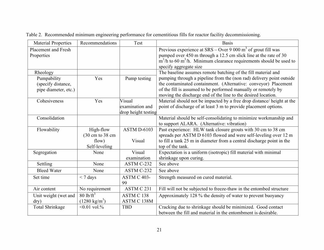
Infills and backfills typically take the form of pumpable, flowable grouts or concretes. Engineering recommendations and applicable tests for infill/backfills are listed in Table 2. The bases for the engineering needs are also provided.
21
Table 2. Recommended minimum engineering performance for cementitious fills for reactor facility decommissioning.
Material Properties Recommendations Test Basis Placement and Fresh Properties
Previous experience at SRS – Over 9 000 m3 of grout fill was pumped over 450 m through a 12.5 cm slick line at the rate of 30 m3/h to 60 m3/h. Minimum clearance requirements should be used to specify aggregate size
Rheology Pumpability (specify distance, pipe diameter, etc.)
Yes Pump testing The baseline assumes remote batching of the fill material and pumping through a pipeline from the (non rad) delivery point outside the contaminated containment. (Alternative: conveyor) Placement of the fill is assumed to be performed manually or remotely by moving the discharge end of the line to the desired location.
Cohesiveness Yes Visual examination and drop height testing
Material should not be impacted by a free drop distance/ height at the point of discharge of at least 3 m to provide placement options.
Consolidation Material should be self-consolidating to minimize workmanship and to support ALARA. (Alternative: vibration)
Flowability High-flow (30 cm to 38 cm
flow) Self-leveling
ASTM D-6103
Visual
Past experience: HLW tank closure grouts with 30 cm to 38 cm spreads per ASTM D 6103 flowed and were self-leveling over 12 m to fill a tank 25 m in diameter from a central discharge point in the top of the tank.
Segregation None Visual examination
Expectation is a uniform (isotropic) fill material with minimal shrinkage upon curing.
Settling None ASTM C-232 See above Bleed Water None ASTM C-232 See above
Set time < 7 days ASTM C 403-99
Strength measured on cured material.
Air content No requirement ASTM C 231 Fill will not be subjected to freeze-thaw in the entombed structure Unit weight (wet and dry)
80 lb/ft3 (1280 kg/m3)
ASTM C 138 ASTM C 138M
Approximately 128 % the density of water to prevent buoyancy
Total Shrinkage <0.01 vol.% TBD Cracking due to shrinkage should be minimized. Good contact between the fill and material in the entombment is desirable.
22
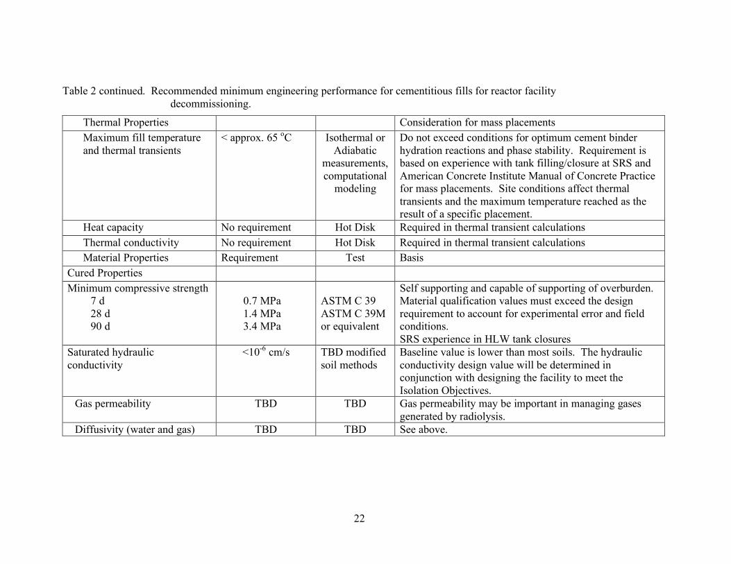
Table 2 continued. Recommended minimum engineering performance for cementitious fills for reactor facility
decommissioning.
Thermal Properties Consideration for mass placements Maximum fill temperature and thermal transients
< approx. 65 oC Isothermal or Adiabatic
measurements, computational
modeling
Do not exceed conditions for optimum cement binder hydration reactions and phase stability. Requirement is based on experience with tank filling/closure at SRS and American Concrete Institute Manual of Concrete Practice for mass placements. Site conditions affect thermal transients and the maximum temperature reached as the result of a specific placement.
Heat capacity No requirement Hot Disk Required in thermal transient calculations Thermal conductivity No requirement Hot Disk Required in thermal transient calculations Material Properties Requirement Test Basis
Cured Properties Minimum compressive strength
7 d 28 d 90 d
0.7 MPa 1.4 MPa 3.4 MPa
ASTM C 39 ASTM C 39M or equivalent
Self supporting and capable of supporting of overburden. Material qualification values must exceed the design requirement to account for experimental error and field conditions. SRS experience in HLW tank closures
Saturated hydraulic conductivity
<10-6 cm/s TBD modified soil methods
Baseline value is lower than most soils. The hydraulic conductivity design value will be determined in conjunction with designing the facility to meet the Isolation Objectives.
Gas permeability TBD TBD Gas permeability may be important in managing gases generated by radiolysis.
Diffusivity (water and gas) TBD TBD See above.
23
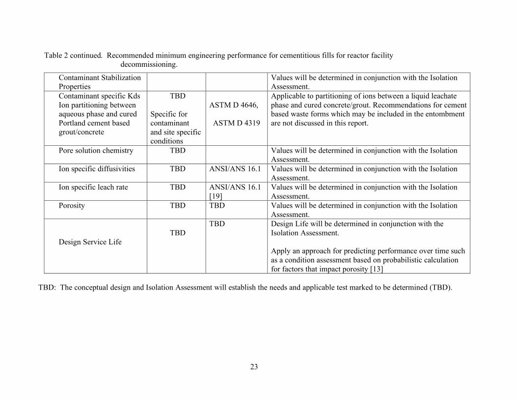
Table 2 continued. Recommended minimum engineering performance for cementitious fills for reactor facility decommissioning.
Contaminant Stabilization Properties
Values will be determined in conjunction with the Isolation Assessment.
Contaminant specific Kds Ion partitioning between aqueous phase and cured Portland cement based grout/concrete
TBD
Specific for contaminant and site specific conditions
ASTM D 4646,
ASTM D 4319
Applicable to partitioning of ions between a liquid leachate phase and cured concrete/grout. Recommendations for cement based waste forms which may be included in the entombment are not discussed in this report.
Pore solution chemistry TBD Values will be determined in conjunction with the Isolation Assessment.
Ion specific diffusivities TBD ANSI/ANS 16.1 Values will be determined in conjunction with the Isolation Assessment.
Ion specific leach rate TBD ANSI/ANS 16.1 [19]
Values will be determined in conjunction with the Isolation Assessment.
Porosity TBD TBD Values will be determined in conjunction with the Isolation Assessment.
Design Service Life
TBD
TBD Design Life will be determined in conjunction with the Isolation Assessment.
Apply an approach for predicting performance over time such as a condition assessment based on probabilistic calculation for factors that impact porosity [13]
TBD: The conceptual design and Isolation Assessment will establish the needs and applicable test marked to be determined (TBD).
24
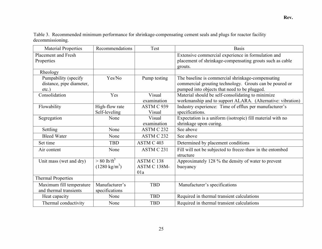
Cementitious materials used as seals or plugs typically take the form of flowable, shrinkage compensating grouts or concretes. Depending on the clearance of the object to be sealed, the grouts may or may not contain fine aggregate. Engineering recommendations and applicable tests for seals/plugs are listed in Table 3. The basis for each engineering recommendation is also provided in the table. Durable encasements can take the form of reinforced concrete, mass concrete, or composite structures that use concrete as a component. Minimum engineering needs and applicable tests for durable encasement concrete are not available, but engineering properties of quality concrete are listed in Table 4 as a starting point for further analysis. The basis for these engineering needs is also provided in the table.
Rev.
25
Table 3. Recommended minimum performance for shrinkage-compensating cement seals and plugs for reactor facility decommissioning.
Material Properties Recommendations Test Basis Placement and Fresh Properties
Extensive commercial experience in formulation and placement of shrinkage-compensating grouts such as cable grouts.
Rheology Pumpability (specify distance, pipe diameter, etc.)
Yes/No Pump testing The baseline is commercial shrinkage-compensating commercial grouting technology. Grouts can be poured or pumped into objects that need to be plugged.
Consolidation Yes Visual examination
Material should be self-consolidating to minimize workmanship and to support ALARA. (Alternative: vibration)
Flowability High-flow rate Self-leveling
ASTM C 939 Visual
Industry experience: Time of efflux per manufacturer’s specifications.
Segregation None Visual examination
Expectation is a uniform (isotropic) fill material with no shrinkage upon curing.
Settling None ASTM C 232 See above Bleed Water None ASTM C 232 See above
Set time TBD ASTM C 403 Determined by placement conditions Air content None ASTM C 231 Fill will not be subjected to freeze-thaw in the entombed
structure Unit mass (wet and dry) > 80 lb/ft3
(1280 kg/m3) ASTM C 138 ASTM C 138M-01a
Approximately 128 % the density of water to prevent buoyancy
Thermal Properties Maximum fill temperature and thermal transients
Manufacturer’s specifications
TBD Manufacturer’s specifications
Heat capacity None TBD Required in thermal transient calculations Thermal conductivity None TBD Required in thermal transient calculations
Rev.
26
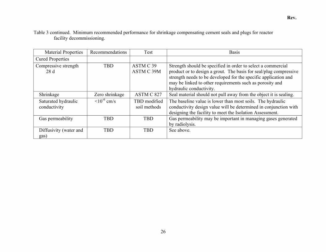
Table 3 continued. Minimum recommended performance for shrinkage compensating cement seals and plugs for reactor facility decommissioning.
Material Properties Recommendations Test Basis
Cured Properties Compressive strength
28 d TBD
ASTM C 39 ASTM C 39M
Strength should be specified in order to select a commercial product or to design a grout. The basis for seal/plug compressive strength needs to be developed for the specific application and may be linked to other requirements such as porosity and hydraulic conductivity.
Shrinkage Zero shrinkage ASTM C 827 Seal material should not pull away from the object it is sealing. Saturated hydraulic conductivity
<10-6 cm/s TBD modified soil methods
The baseline value is lower than most soils. The hydraulic conductivity design value will be determined in conjunction with designing the facility to meet the Isolation Assessment.
Gas permeability TBD TBD Gas permeability may be important in managing gases generated by radiolysis.
Diffusivity (water and gas)
TBD TBD See above.
Rev.
27
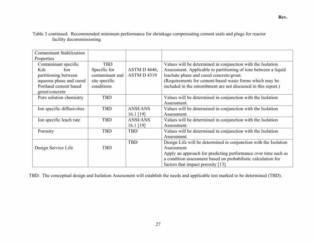
Table 3 continued. Recommended minimum performance for shrinkage compensating cement seals and plugs for reactor facility decommissioning.
Contaminant Stabilization Properties
Contaminant specific Kds Ion partitioning between aqueous phase and cured Portland cement based grout/concrete
TBD Specific for contaminant and site specific conditions
ASTM D 4646, ASTM D 4319
Values will be determined in conjunction with the Isolation Assessment. Applicable to partitioning of ions between a liquid leachate phase and cured concrete/grout. (Requirements for cement-based waste forms which may be included in the entombment are not discussed in this report.)
Pore solution chemistry TBD Values will be determined in conjunction with the Isolation Assessment.
Ion specific diffusivities TBD ANSI/ANS 16.1 [19]
Values will be determined in conjunction with the Isolation Assessment.
Ion specific leach rate TBD ANSI/ANS 16.1 [19]
Values will be determined in conjunction with the Isolation Assessment.
Porosity TBD TBD Values will be determined in conjunction with the Isolation Assessment.
Design Service Life
TBD
TBD Design Life will be determined in conjunction with the Isolation Assessment. Apply an approach for predicting performance over time such as a condition assessment based on probabilistic calculation for factors that impact porosity [13]
TBD: The conceptual design and Isolation Assessment will establish the needs and applicable test marked to be determined (TBD).
Rev.
28
Table 4. Recommended minimum performance for cementitious materials used for encasements in reactor facility decommissioning.
Material Properties Recommendations Test Basis Placement and Fresh Properties
Extensive design and construction experience is available.
Rheology Pumpability (specify distance, pipe diameter, etc.)
Yes Pump testing The baseline depends on design and field conditions. Pumping is assumed.
Slump TBD ASTM C 143 Depends on restrictions from rebar and ability to use vibration to achieve consolidation
Segregation Minimal Visual examination
Expectation is a uniform (isotropic) fill material with no shrinkage upon curing.
Settling None ASTM C 232 See above Bleed Water None ASTM C 232 See above
Set time TBD ASTM C 403 Determined by placement conditions. Air content TBD ASTM C 231 Concrete used in a durable encasement should be designed for
freeze-thaw resistance. Unit mass (wet and dry) >140 lb/ft3
(2240 kg/m3) ASTM C 138 ASTM C 138M
Durable concrete should have low porosity. Non porous aggregates should be specified and the matrix should be designed to be very low porosity.
Thermal Properties Maximum fill temperature and thermal transients
TBD TBD Requirements depend on construction scenario.
Heat capacity None TBD Required in thermal transient calculations Thermal conductivity None TBD Required in thermal transient calculations
Rev.
29
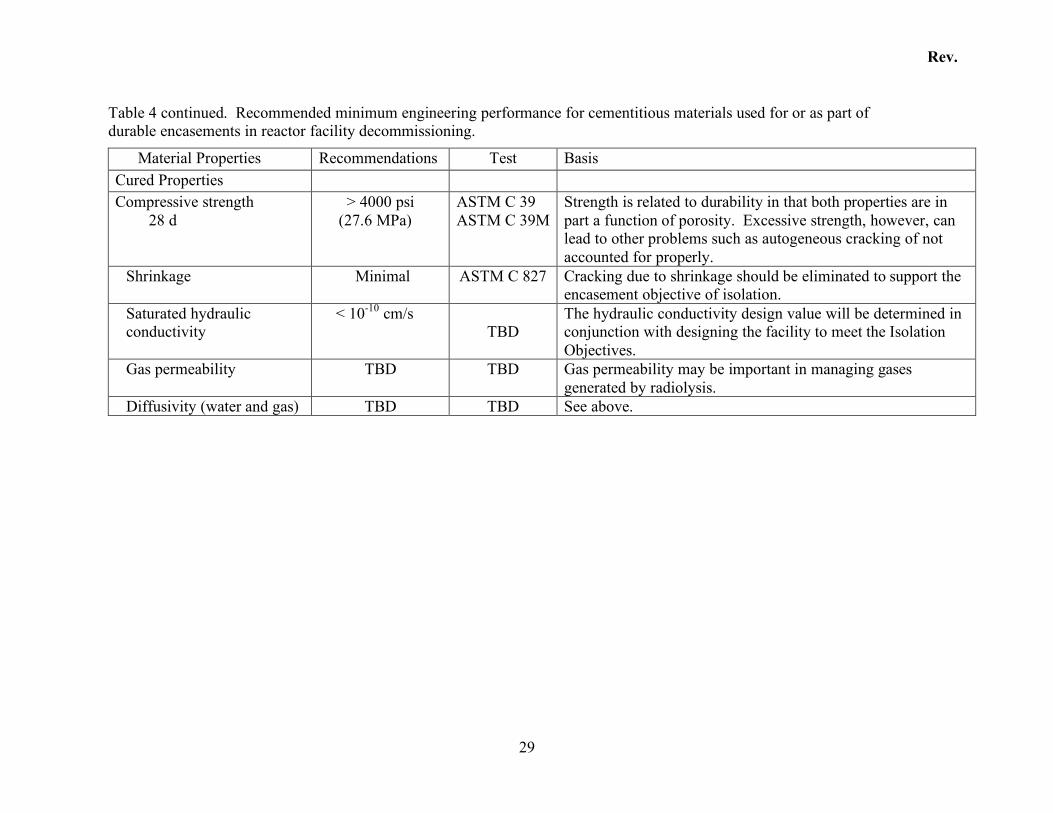
Table 4 continued. Recommended minimum engineering performance for cementitious materials used for or as part of durable encasements in reactor facility decommissioning.
Material Properties Recommendations Test Basis Cured Properties Compressive strength
28 d > 4000 psi
(27.6 MPa) ASTM C 39 ASTM C 39M
Strength is related to durability in that both properties are in part a function of porosity. Excessive strength, however, can lead to other problems such as autogeneous cracking of not accounted for properly.
Shrinkage Minimal ASTM C 827 Cracking due to shrinkage should be eliminated to support the encasement objective of isolation.
Saturated hydraulic conductivity
< 10-10 cm/s TBD
The hydraulic conductivity design value will be determined in conjunction with designing the facility to meet the Isolation Objectives.
Gas permeability TBD TBD Gas permeability may be important in managing gases generated by radiolysis.
Diffusivity (water and gas) TBD TBD See above.
Rev.
30
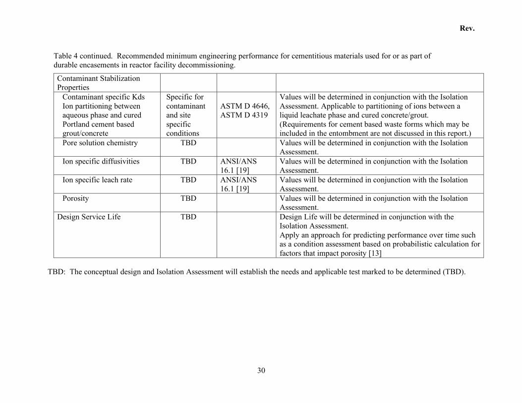
Table 4 continued. Recommended minimum engineering performance for cementitious materials used for or as part of durable encasements in reactor facility decommissioning.
Contaminant Stabilization Properties
Contaminant specific Kds Ion partitioning between aqueous phase and cured Portland cement based grout/concrete
Specific for contaminant and site specific conditions
ASTM D 4646, ASTM D 4319
Values will be determined in conjunction with the Isolation Assessment. Applicable to partitioning of ions between a liquid leachate phase and cured concrete/grout. (Requirements for cement based waste forms which may be included in the entombment are not discussed in this report.)
Pore solution chemistry TBD Values will be determined in conjunction with the Isolation Assessment.
Ion specific diffusivities TBD ANSI/ANS 16.1 [19]
Values will be determined in conjunction with the Isolation Assessment.
Ion specific leach rate TBD ANSI/ANS 16.1 [19]
Values will be determined in conjunction with the Isolation Assessment.
Porosity TBD Values will be determined in conjunction with the Isolation Assessment.
Design Service Life TBD Design Life will be determined in conjunction with the Isolation Assessment. Apply an approach for predicting performance over time such as a condition assessment based on probabilistic calculation for factors that impact porosity [13]
TBD: The conceptual design and Isolation Assessment will establish the needs and applicable test marked to be determined (TBD).
Rev.
31
2.4.2 Approaches to Predicting Long-Term Performance
Predicting changes in materials as a function of time is addressed in several different ways. One method uses past experience. This approach has limited application for evaluating cementitious materials used in entombments requiring isolation periods of more than 100 years. However, useful information about deterioration mechanisms can be obtained via an assessment of very aged concrete and structures. Thermodynamic data and analogies with old and ancient building materials and geologic media can provide information on material stability, in particular the phases making up the cementitious entombment materials. However, it is not adequate for evaluating durability of structures since few old or ancient structures are performing as originally intended. Those that are, have been well maintained in addition to having been well designed. Long-term testing and accelerated aging/testing are also useful for comparison evaluations and rate determinations. However, the mechanisms responsible for the phenomena being evaluated must remain unchanged by the accelerated conditions. Extrapolation of the results over the long times required for isolation of a nuclear facility entombment requires extensive testing and data interpretation. The approach used for LLW landfill performance is to assume that engineered barriers perform their design function with reasonable certainty for 500 years after which time no credit is given for performance. Credit for performance beyond 500 years is possible if supporting data is provided on a case-by-case basis. By comparison, a probabilistic evaluation of deterioration was investigated to develop guidelines for the chemical and material assessment of an entombment structure. This work has been presented elsewhere [20].
2.4.3 Time Dependent (Aging) Factors Affecting Performance
A brief summary of factors affecting long-term performance is presented. These factors should be taken into account during the feasibility study phase of the project. Selecting appropriate ingredients for the cementitious materials and minimizing the porosity are conventional strategies for mitigating degradation caused by environmental factors. Selecting compatible ingredients is the strategy for preventing internal stresses that can degrade cementitious materials long after they have been put in service. Selecting appropriate starting materials is essential for achieving the long term performance with respect to contaminant isolation. There are many references that provide overviews of factors affecting performance, materials and methods for mitigating detrimental effects [21]
2.4.3.1 Environmental Factors Affecting Durability
In a completed ENTOMB decommissioning, cementitious components (infill/backfill, seals/plugs, and durable encasement structure) can be deleteriously affected by external chemical

Rev.
32
factors. The durable encasement is the most susceptible to external processes since it provides the physical barrier that isolates the radioactively contaminated portion of the entombment form the environment. External processes, such as leaching by groundwater or infiltrating water, carbonation, and/or chemical oxidation/reduction of the hydrated cement phases (and aggregates) typically affect the entire surface in contact with the environment. Corrosive chemicals such as sulfates and/or chlorides in the water contacting the cementitious material can greatly accelerate deterioration. Chemical, microstructural and mineralogical changes related to the deterioration caused by environmental chemistry are typically expressed as spalling and cracking on the exposed surface; these effects advance into the concrete with exposure time. Mitigating concrete deterioration caused by exposure to aggressive environmental media typically requires that the concrete mixture is designed so as to reduce the capillary porosity, the permeability, and the diffusivity. This is typically accomplished by a number of commonly accepted engineering practices:
1. Reducing the water content to as low as possible by including surfactants (water reducers or high-range water reducers) in the fresh concrete/grout mixes.
2. Reducing the amount of the most soluble phases, such as, calcium hydroxide (portlandite) by including pozzolans in the mix design.
3. Specifying the particle size distribution of the binder ingredients, including an ultra fine fraction, such as silica fume, and specifying the sand and aggregate grading to optimize volume filling.
2.4.3.2 Internal Factors Affecting Durability
In a completed ENTOMB decommissioning, cementitious components can also be deleteriously affected by internal chemical factors. These effects can be controlled by mix design, materials compatibility, cement chemistry and aggregate mineralogy, water content, and particle size distribution. Any of the structural components for an ENTOMB decommissioning may be deleteriously affected by internal factors. Generally internal factors affecting durability require an external perturbation (moisture intrusion) to initiate the deleterious effects. Thus, remedies used to mitigate external deterioration effects (reduced water content, reducing soluble phases and specifying particle size including pozzolans) are also useful in mitigating deterioration caused by internal factors. Internal durability problems include: delayed ettringite formation (DEF), alkali silica reaction (ASR), cracking due to heat of hydration, and shrinkage. DEF is a form of internal sulfate attack caused by ettringite not forming while the grout/concrete is plastic, but after set. An elevated temperature is required during curing, either induced during man made processing or by cement reaction. ASR is caused by the dissolution of reactive siliceous aggregate due to the hydroxyl ions present in the hydrating cement (and highly dependent on alkali content) and the available aggregate surface area (fine grained aggregate are much more susceptible). Both DEF and ASR require the movement of water through the grout/concrete system to induce the reactions.
Rev.
33
Heat of hydration is produced by the exothermic reaction between the water and the cementitious components. If the heat of hydration is too great, cracks can form due to differential temperature gradients within a mass concrete structure, especially during its “cooling” phase. The heat of hydration is controlled by the mix design; adding pozzolanic materials such as fly ash can greatly limit both the rate of temperature change and the maximum temperature attained. Improperly cured (hydrated) concrete or grout can also lead to increased porosity, which in turn makes the structure more susceptible to external factors; again affecting durability. Autogeneous shrinkage is the most easily controlled internal factor for durability. As cement hydrates and cures, the net affect is for the grout or concrete to shrink. Shrinkage can be mitigated through mix design and proper curing; incorporation of expansive phases to compensate for the shrinkage (this can be difficult to control in practice), and by proper aggregate/sand size distribution. Pozzolans added to the mix need to be tested to assure sufficient quality. Chemical compositions, particle size distributions and relative reactivity (or lack there of) all may act to enhance deterioration. Mix performance can be compromised by inadvertently adding chlorides, sulfates and/or carbon through the introduction of certain types of fly ash, slag or silica fume. Variations in particle size distributions, such as that of silica fume, can lead to enhanced susceptibility to ASR. Standard materials testing by ASTM methods can alleviate these problems.
Rev.
34
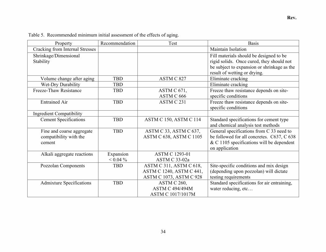
Table 5. Recommended minimum initial assessment of the effects of aging.
Property Recommendation Test Basis Cracking from Internal Stresses Maintain Isolation Shrinkage/Dimensional Stability
Fill materials should be designed to be rigid solids. Once cured, they should not be subject to expansion or shrinkage as the result of wetting or drying.
Volume change after aging TBD ASTM C 827 Eliminate cracking Wet-Dry Durability TBD Eliminate cracking
Freeze-Thaw Resistance TBD ASTM C 671, ASTM C 666
Freeze thaw resistance depends on site-specific conditions
Entrained Air TBD ASTM C 231 Freeze thaw resistance depends on site-specific conditions
Ingredient Compatibility Cement Specifications TBD ASTM C 150, ASTM C 114 Standard specifications for cement type
and chemical analysis test methods Fine and coarse aggregate compatibility with the cement
TBD ASTM C 33, ASTM C 637, ASTM C 638, ASTM C 1105
General specifications from C 33 need to be followed for all concretes. C637, C 638 & C 1105 specifications will be dependent on application
Alkali aggregate reactions Expansion < 0.04 %
ASTM C 1293-01 ASTM C 33-02a
Pozzolan Components TBD ASTM C 311, ASTM C 618, ASTM C 1240, ASTM C 441, ASTM C 1073, ASTM C 928
Site-specific conditions and mix design (depending upon pozzolan) will dictate testing requirements
Admixture Specifications TBD ASTM C 260, ASTM C 494/494M
ASTM C 1017/1017M
Standard specifications for air entraining, water reducing, etc…
Rev.
35
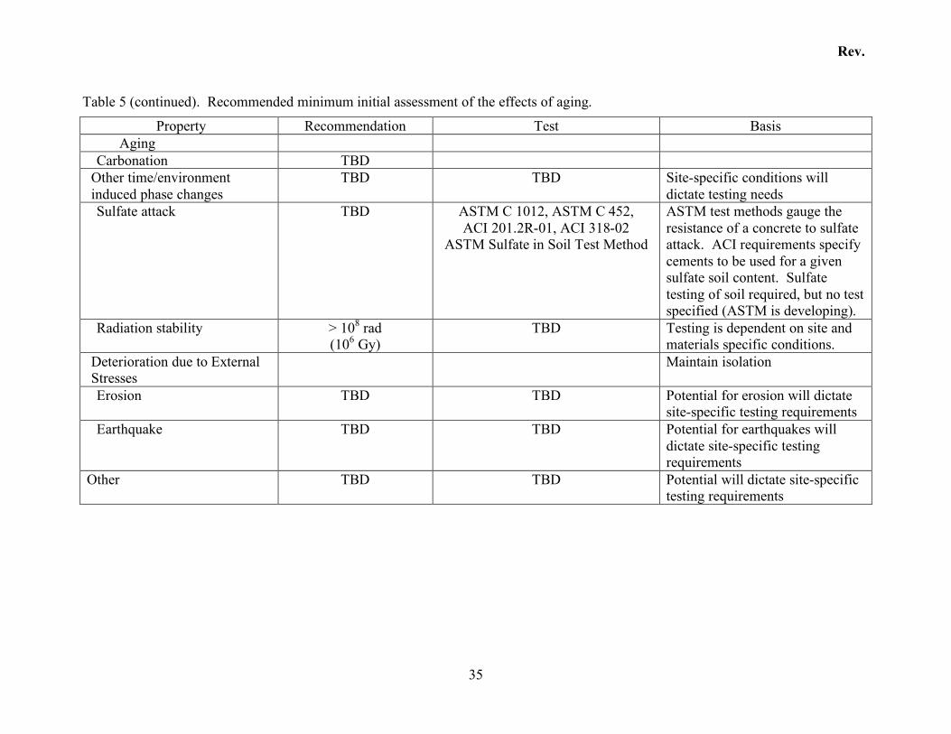
Table 5 (continued). Recommended minimum initial assessment of the effects of aging.
Property Recommendation Test Basis Aging
Carbonation TBD Other time/environment induced phase changes
TBD TBD Site-specific conditions will dictate testing needs
Sulfate attack TBD ASTM C 1012, ASTM C 452, ACI 201.2R-01, ACI 318-02
ASTM Sulfate in Soil Test Method
ASTM test methods gauge the resistance of a concrete to sulfate attack. ACI requirements specify cements to be used for a given sulfate soil content. Sulfate testing of soil required, but no test specified (ASTM is developing).
Radiation stability > 108 rad (106 Gy)
TBD Testing is dependent on site and materials specific conditions.
Deterioration due to External Stresses
Maintain isolation
Erosion TBD TBD Potential for erosion will dictate site-specific testing requirements
Earthquake TBD TBD Potential for earthquakes will dictate site-specific testing requirements
Other TBD TBD Potential will dictate site-specific testing requirements
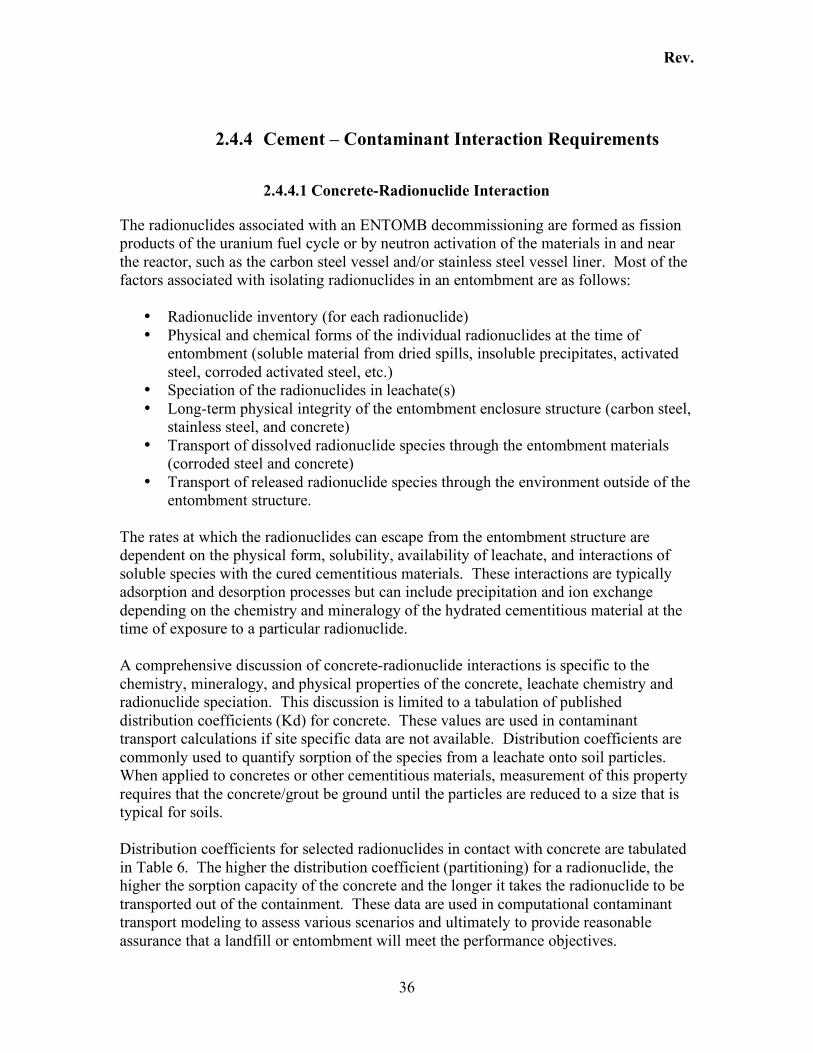
Rev.
36
2.4.4 Cement – Contaminant Interaction Requirements
2.4.4.1 Concrete-Radionuclide Interaction
The radionuclides associated with an ENTOMB decommissioning are formed as fission products of the uranium fuel cycle or by neutron activation of the materials in and near the reactor, such as the carbon steel vessel and/or stainless steel vessel liner. Most of the factors associated with isolating radionuclides in an entombment are as follows:
• Radionuclide inventory (for each radionuclide) • Physical and chemical forms of the individual radionuclides at the time of
entombment (soluble material from dried spills, insoluble precipitates, activated steel, corroded activated steel, etc.)
• Speciation of the radionuclides in leachate(s) • Long-term physical integrity of the entombment enclosure structure (carbon steel,
stainless steel, and concrete) • Transport of dissolved radionuclide species through the entombment materials
(corroded steel and concrete) • Transport of released radionuclide species through the environment outside of the
entombment structure.
The rates at which the radionuclides can escape from the entombment structure are dependent on the physical form, solubility, availability of leachate, and interactions of soluble species with the cured cementitious materials. These interactions are typically adsorption and desorption processes but can include precipitation and ion exchange depending on the chemistry and mineralogy of the hydrated cementitious material at the time of exposure to a particular radionuclide. A comprehensive discussion of concrete-radionuclide interactions is specific to the chemistry, mineralogy, and physical properties of the concrete, leachate chemistry and radionuclide speciation. This discussion is limited to a tabulation of published distribution coefficients (Kd) for concrete. These values are used in contaminant transport calculations if site specific data are not available. Distribution coefficients are commonly used to quantify sorption of the species from a leachate onto soil particles. When applied to concretes or other cementitious materials, measurement of this property requires that the concrete/grout be ground until the particles are reduced to a size that is typical for soils. Distribution coefficients for selected radionuclides in contact with concrete are tabulated in Table 6. The higher the distribution coefficient (partitioning) for a radionuclide, the higher the sorption capacity of the concrete and the longer it takes the radionuclide to be transported out of the containment. These data are used in computational contaminant transport modeling to assess various scenarios and ultimately to provide reasonable assurance that a landfill or entombment will meet the performance objectives.
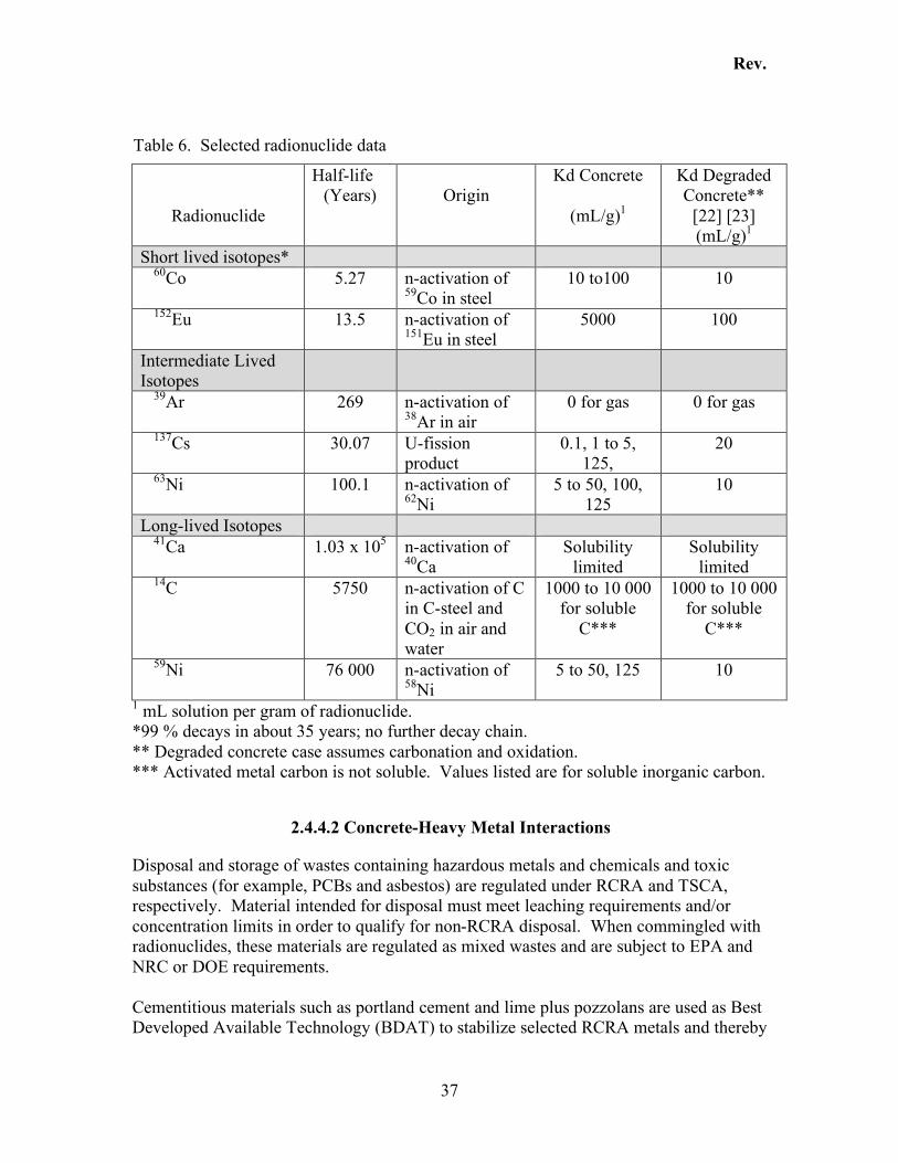
Rev.
37
Table 6. Selected radionuclide data
Radionuclide
Half-life (Years)
Origin
Kd Concrete
(mL/g)1
Kd Degraded Concrete**
[22] [23] (mL/g)1
Short lived isotopes* 60Co 5.27 n-activation of
59Co in steel 10 to100 10
152Eu 13.5 n-activation of 151Eu in steel
5000 100
Intermediate Lived Isotopes
39Ar 269 n-activation of 38Ar in air
0 for gas 0 for gas
137Cs 30.07 U-fission product
0.1, 1 to 5, 125,
20
63Ni 100.1 n-activation of 62Ni
5 to 50, 100, 125
10
Long-lived Isotopes 41Ca 1.03 x 10⁵ n-activation of
40Ca Solubility
limited Solubility
limited 14C 5750 n-activation of C
in C-steel and CO2 in air and water
1000 to 10 000 for soluble
C***
1000 to 10 000 for soluble
C***
59Ni 76 000 n-activation of 58Ni
5 to 50, 125 10
1 mL solution per gram of radionuclide. *99 % decays in about 35 years; no further decay chain. ** Degraded concrete case assumes carbonation and oxidation. *** Activated metal carbon is not soluble. Values listed are for soluble inorganic carbon.
2.4.4.2 Concrete-Heavy Metal Interactions
Disposal and storage of wastes containing hazardous metals and chemicals and toxic substances (for example, PCBs and asbestos) are regulated under RCRA and TSCA, respectively. Material intended for disposal must meet leaching requirements and/or concentration limits in order to qualify for non-RCRA disposal. When commingled with radionuclides, these materials are regulated as mixed wastes and are subject to EPA and NRC or DOE requirements. Cementitious materials such as portland cement and lime plus pozzolans are used as Best Developed Available Technology (BDAT) to stabilize selected RCRA metals and thereby
Rev.
38
render them suitable for disposal. Metals such as barium, lead and cadmium form low solubility metal hydroxides in alkaline matrices. The rates at which toxic substances (RCRA hazardous metal) can escape from the entombment structure are dependent on the same factors as the radionuclides, i.e., physical form, solubility, and interactions with the cured cementitious materials. These interactions are typically adsorption and desorption processes but can include precipitation and ion exchange depending on the chemistry and mineralogy of the cured cementitious material at the time of exposure to a particular radionuclide.
2.5 Materials Specification/Selection
Cement-based construction materials, used in an entombment decommissioning, are procured by one of several types of procurement specifications:
• Performance specifications • Materials specifications • Hybrid specification (A special ingredient(s) may be required to meet a particular
objective but the overall mix design is supplied based on performance specifications)
The approach to materials specification should be addressed in the conceptual planning or feasibility stages of the project, when the strategy for providing reasonable assurance of performance is developed. If the material specification option is selected, the design authority or designee develops and tests materials to qualify them for various applications in the entombment construction. If the performance requirements are outside of the range obtained by employing expert commercial knowledge, this approach is very useful to reduce risk during later stages of the project. If performance specifications are selected, the design authority must have reasonable assurance that potential expert suppliers can produce materials that meet the requirements. Performance specifications allow suppliers to make adjustments in proportions and ingredients to provide the most cost effective product materials at the time and location of the construction job. Performance specifications are used to procure most concrete used in the construction industry.
2.5.1 Performance Specifications
2.5.1.1 Placement
Performance specifications are adequate to procure fill materials that meet placement requirements. The concrete manufacturing and construction industries have extensive experience in this area. However, unique or unusual design details may result in placement requirements that are outside the range of experience. Consequently, mock-up
Rev.
39
testing should be performed to identify these performance requirements prior to finalizing a performance specification. Placement of flowable, self compacting, self leveling, zero bleed grouts has been demonstrated. For example, pumping fill grouts over 450 m was required to fill two SRS HLW tanks in 1997. These grouts were pumped through a 12 cm slick line at the rate of 30 m3/h to 60 m3/h. Over 9000 m3 of grout were used to close two 1.3 x 10⁶ gal (4700 m3) underground tanks. Each tank was filled in less than one month. Performance specifications are also adequate for fresh properties of shrinkage compensating cementitious plug/seal materials. These materials are used in numerous construction applications including cable grouting. Again, mock-up testing may be necessary to adequately specify the fresh properties of these materials given the specific details and field conditions dictated by the project design. Performance specifications are also adequate for placement of durable concrete used as part or all of the entombment encasement structure. Extensive industry experience is available to support this type of specification with respect to placement properties.
2.5.1.2 Cured Properties
Performance specifications for cured properties are adequate for most construction applications. However, they may not be appropriate for addressing the complete set of requirements for entombment applications. In particular, interaction between the cement materials and the radionuclides and very long-term performance requirements are beyond the scope of typical construction experience.
2.5.1.3 Leaching and Long-Term Properties
Performance specifications for leaching and long-term properties are not practical given the current state of knowledge. A basis for selecting a particular test or set of tests must first be developed. A methodology for predicting the time dependency of the performance must also be developed and accepted by the regulatory agencies and stakeholders.
2.5.2 Materials Specifications
A materials specification identifies the ingredients in the material to be supplied. One or more design mixes must be developed, tested and accepted (qualified) as meeting the requirements. The initial materials development program must be carried out in order to use this approach.
Rev.
40
2.5.2.1 Proportioning Guidelines
The American Concrete Institute Manual of Standard Practice [24] and other similar sources of information [25, 26] provide proportioning guidelines for concrete and fill materials. This information can be used as a starting place for materials selection and proportioning. In general, only compatible materials should be considered. The capillary porosity should be minimized by reducing the total volume of water in the mix. Further improvements can be achieved by selecting and proportioning the binder ingredients to produce the least porous microstructure. Chemical processing additives to achieve the desired processing properties and reagents to reduce leaching of radionuclides isolated in the containment should also be specified.
2.5.2.2 Testing Protocols
ASTM standard grout/concrete tests [27] are suitable for measuring placement properties for fills, seals, and encasement materials. However, field testing may be required to identify ranges of acceptable properties. ASTM tests are also suitable for measuring physical properties of cured cement-based materials. However, test protocols for some properties, such as, porosity, diffusivity, leaching, sorption and effects of aging require a review of methods and possibly method development for entombment applications.
2.6 Entombment Constructability
2.6.1 Overview
A discussion of constructability typically begins with identification of a specific viewpoint, i.e., the owner’s viewpoint, the project design/engineering viewpoint (design process), the constructor/builder’s viewpoint (the construction project management process), the public/stakeholder’s viewpoint, the regulator’s viewpoint, etc. In the following overview, many points of view are represented but the main focus is on risk of project failure (failure to construct to design specifications) rather than on risks associated with cost, schedule, etc. Constructability, as it relates to an ENTOMB decommissioning, is divided into five parts: 1) Preconstruction, 2) Design and Engineering, 3) Procurement and Construction, 4) Operation, and 5) End of Service. A simplified project life cycle for an ENTOMB decommissioning is schematically illustrated in Figure 11 (modified from Ref. 28). Key features of constructability are a clear description and understanding of the project and application of existing design knowledge and implementation experience. Case studies and lessons learned are invaluable tools for evaluating project feasibility and minimizing cost and schedule. A partial list of ENTOMB decommissioning issues and experiences, in addition to experience in related fields such as LLW landfills and large
Rev.
41
volume construction placements of infills and backfills and encasement construction are listed in Table 7. Case studies and lessons learned are beyond the scope of this report. Constructability reviews are typically implemented as a formalized process and are used by most project owners and managers. The reviews take place in all phases of a project life-cycle. For all projects, especially an ENTOMB decommissioning, the greatest risk of project failure is encountered in the early stages of a project, i.e., Preconstruction and Design/Engineering Stages.
2.6.2 Preconstruction
The Preconstruction Constructability Review (Needs Assessment, Conceptual Planning, and Feasibility Study) should be used to reduce/eliminate risk associated with regulatory interpretations, stakeholder objections, built-in conflicts, discrepancies, ambiguities and impossibilities. During this stage of a project, constructability focuses on developing concepts and methodologies that support the objectives and needs. Contract language, assumption of liability, and potential for litigation delays must also be reviewed and evaluated with respect to success or failure of the project. An assessment of overall risk and risk management during the project are essential parts of the preconstruction constructability review.
2.6.3 Design and Engineering
Constructability Reviews during the Design and Engineering Stages of a project are used to confirm technical feasibility and design efficiency. These reviews utilize a multidisciplinary team approach to integrate construction knowledge and experience into the design. The focus of constructability reviews at this stage is on assuring that: 1) the design meets the overall performance objectives, 2) the details of the design meet engineering specifications and materials specifications, 3) specifications are constructable and materials can be procured, and 4) the overall work scope supports a controlled and predictable building process. Value Engineering studies and Alternatives studies are usually initiated at an early stage in the design phase and can result in significant modifications and improvements of the concept and preliminary design.
2.6.4 Procurement and Construction
The Construction Industry Institute (CII) defines constructability as, “The optimum use of the construction knowledge and experience in planning, design/engineering, procurement, and field operations to achieve overall project objectives.” During this stage of a project, a constructability review takes advantage of existing knowledge and experience to provide the maximum benefit as measured by the impact on cost. These reviews are an intense cross check. They focus on identifying missed details, faulty
Rev.
42
working drawings and incomplete specifications and potential liabilities. The goal is to produce accurate, well-coordinated plans and specifications to minimize change orders and optimize field administration. Risk evaluation and the assumption of unavoidable risks associated with various construction activities, e.g., project planning (scheduling), quality control, cost estimation, economic evaluation, forecasting, etc. are also part of this constructability evaluation.
2.6.5 Operation
An ENTOMB decommissioning results in a facility that operates passively with the exception of monitoring and surveillance. Constructability reviews applicable to this phase of a project must be addressed in the overall scope of the project.
2.6.6 Facility Disposal
An ENTOMB decommissioning results in a facility isolated (disposed of) in-place. The design path (roadmap) by which the facility gets released from institutional control should be reviewed and periodically updated by the owners, stakeholders, and regulators as part of the constructability assessment.
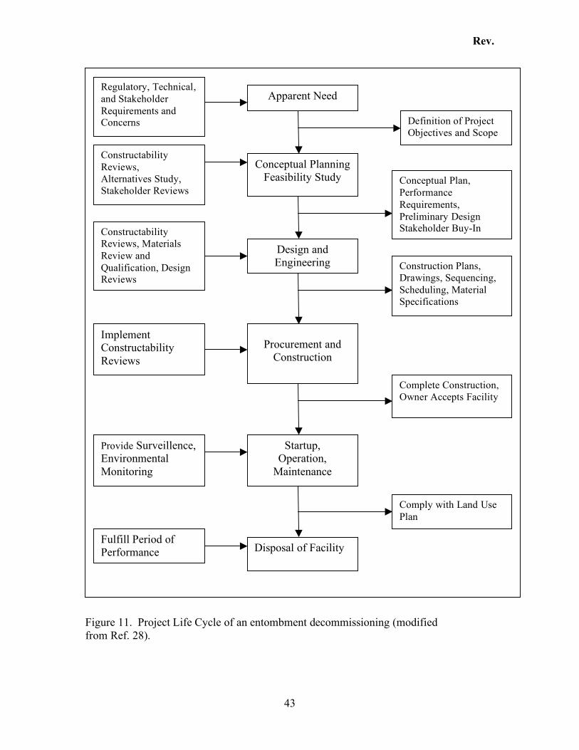
Rev.
43
Figure 11. Project Life Cycle of an entombment decommissioning (modified from Ref. 28).
Conceptual Planning Feasibility Study
Design and Engineering
Procurement and Construction
Startup, Operation,
Maintenance
Disposal of Facility
Apparent Need
Definition of Project Objectives and Scope
Conceptual Plan, Performance Requirements, Preliminary Design Stakeholder Buy-In
Construction Plans, Drawings, Sequencing, Scheduling, Material Specifications
Complete Construction, Owner Accepts Facility
Comply with Land Use Plan
Constructability Reviews, Alternatives Study, Stakeholder Reviews
Constructability Reviews, Materials Review and Qualification, Design Reviews
Regulatory, Technical, and Stakeholder Requirements and Concerns
Implement Constructability Reviews
Fulfill Period of Performance
Provide Surveillence, Environmental Monitoring
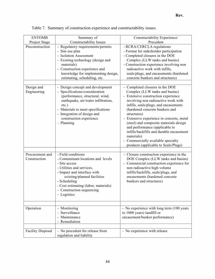
Rev.
44
Table 7. Summary of construction experience and constructability issues. ENTOMB
Project Stage Summary of
Constructability Issues Constructability Experience/
Precedent Preconstruction - Regulatory requirements/permits
- Site use plan - Isolation Assessment - Existing technology (design and
materials) - Construction experience and
knowledge for implementing design, estimating, scheduling, etc.
- RCRA/CERCLA regulations - Format for stakeholder participation - Completed closures in the DOE
Complex (LLW tanks and basins) - Construction experience involving non
radioactive work with infills, seals/plugs, and encasements (hardened concrete bunkers and structures)
Design and Engineering
- Design concept and development - Specifications/consideration
(performance, structural, wind, earthquake, air/water infiltration, etc.)
- Materials to meet specifications - Integration of design and
construction experience - Planning
- Completed closures in the DOE Complex (LLW tanks and basins) - Extensive construction experience
involving non radioactive work with infills, seals/plugs, and encasements (hardened concrete bunkers and structures)
- Extensive experience in concrete, metal (steel) and composite materials design and performance (applicable to infills/backfills and durable encasement materials)
- Commercially available specialty products (applicable to Seals/Plugs)
Procurement and Construction
- Field conditions - Contaminant locations and levels - Site access - Utilities and services, - Impact and interface with
existing/planned facilities - Scheduling - Cost estimating (labor, materials) - Construction sequencing - Logistics
- Closure construction experience in the DOE Complex (LLW tanks and basins)
- Commercial construction experience for non radioactive high volume infills/backfills, seals/plugs, and encasements (hardened concrete bunkers and structures)
Operation - Monitoring
- Surveillance - Maintenance - Remediation
- No experience with long term (100 years to 1000 years) landfill or encasement/bunker performance)
Facility Disposal - No precedent for release from
regulation and liability - No experience with release
Rev.
45
3 Infill and Backfill Rheological Properties
3.1 Introduction
In order to decommission a nuclear plant and prevent any impact to the environment, one proposal is to entomb the facility using a cementitious grout as the barrier material. To achieve this objective, the properties of the grout and its constituent materials need to be determined. Here, a literature review will concentrate on definitions, required properties, and potential types of materials and methods to test the grout. Then, some suggestions on types of materials and pre-qualification tests will be given.
3.2 Definitions
There are two types of definition sets that need to be addressed: 1) grout constituents and 2) grout properties. An important property of a grout is workability. Therefore, this report will examine the various types of grout available, and the relevant rheological properties. The presentation is given in the context of the purpose that the grout should fulfill.
3.2.1 Grout definitions
According to ACI [29], a grout is “a mixture of cementitious material and water, with or without aggregates, proportioned to produce a pourable consistency without segregation of the constituents”. ACI also gives additional specific definitions for various types of grouts, such as colloidal, epoxy, neat cement, and hydraulic cement. The main difference between these grouts is the composition of some of the constituents and/or the application [30, 31]:
Colloidal: substantial proportion of the solid particles are between 1 nm and 1 µm [29]
Neat cement: grout without aggregates Hydraulic cement: the cementitious material is hydraulic cement. Chemical grouts: grouts that are sodium silicate, epoxy or resin based
Rev.
46
In Refs. 30 and 31, the various application methods of grouts are described:
Permeation grouting: grout injected in a structure to fill voids. These voids are assumed to be small, such as cracks or the space between rocks.
Compaction grouting (also called compensation grouting): injecting grouts into soil to fill all the voids between the soil particles or larger voids. The purpose is to consolidate the soil.
Jet grouting: a pipe inserted into the soil will spray air or water to create a hole that is then filled with grout. This procedure can create columns used to support a structure.
Vacuum grouting: this method is used to fill small defects in a structure where pressure alone will not allow the grout to penetrate, so a vacuum is created within the void to preferentially draw the grout into the void.
Void filling: this technique refers to any method used to completely fill an abandoned underground mine (coal mines are the most typical)
For decommissioning, there will be both large and small volumes to fill. The smaller volumes will typically have smaller access areas, such as pipes within the facility. The large volumes are any space outside the pipes, such as the rooms, and water basins. Therefore, this review will focus on void filling techniques, and include discussion of the permeation or compaction grouting for the smaller areas. Because cost is often a consideration and because this report focuses on cementitious grouts, the colloidal and epoxy grouts will not be discussed further.
3.2.2 Rheology
The main property mentioned in the ACI definition of grouts is “pourable consistency” with no segregation. Although the meaning of pourable consistency can be imagined, a concise definition does not exist. ACI does define consistency as “the relative mobility or ability of fresh mixed concrete or mortar to flow.” [29] Grout can be approximated by a mortar, but there is no definition of pourable. It could be assumed that the definition implies that the grout will flow into the molds or any void without the use of external force such as vibration, and that it will also be pumpable. Another way to look at it is to decide that pourable is synonymous with flowable. The definition of flowable [29] for a grout is defined by two measurements: 1) flow table: 125 % of the original diameter after five drops; and 2) an efflux time of more than 30 s using the flow cone. Another related term is fluid consistency defined [29] as an efflux time from the flow cone of less than 30 s. ACI also defines a consistency factor as a “measure of grout fluidity, roughly analogous to viscosity, that describes the ease with which grout may be pumped into voids or fissures; based on a laboratory measurement in which consistency is reported in degree of rotation of a torque viscometer in a specimen of grout”. This last term makes direct reference to viscosity. Unfortunately, grouts are
Rev.
47
not simple Newtonian fluids whose flow is defined solely by the viscosity. It is in general believed that grouts are Bingham fluids defined by the following equation:
!"## &$+=0 (1)
where τ = shear stress
τ0 = Yield stress or the stress needed for initiating flow η = Plastic viscosity or the slope of the shear stress vs. shear rate curve !& = Shear rate
When τ0 is equal to zero, the fluid is Newtonian. The yield stress is sometimes referred to as cohesion. The yield stress and the plastic viscosity will determine how easy it would be for the material to completely fill a cavity. Another concept that needs to be defined is thixotropy. Thixotropy is “a reversible time-dependent decrease in viscosity at a particular shear rate. Shearing causes a gradual breakdown in structure over time” [32]. This property implies that, after shearing the grout at a high shear rate, the grout microstructure could be destroyed and, therefore, less shear stress would be needed to shear the grout subsequently. In other words this could reduce the amount of pressure or energy needed to fill voids after initial movement is obtained. Another factor to consider is the time-dependence of flow and setting time. Set is defined [29] as “the condition reached by a cement paste, mortar or concrete when it has lost plasticity to an arbitrary degree, usually measured in terms of resistance to penetration of deformation”. Usually, it is measured for cement paste using the Vicat needle (see 3.3.1). Recently, some tests [33] were performed using another approach based on the evolution of yield stress. The idea is that the yield stress will sharply increase when initial setting time is reached. The next factor to take into consideration when characterizing the flow of grouts is the shear rate dependence of the viscosity. Ideally, the grouts should have a low viscosity at high shear rate during placement, but high viscosity at rest (low shear rate) to avoid segregation [34] or bleeding. In designing the grout for a specific application, it should be kept in mind that the rheological properties are affected by the mixing energy, the duration of mixing, and the delivery system (pumping or pouring). Therefore, the constituents need to be selected to obtain the desired flow for the application. In the case of an entombed facility, the grout yield stress should be low to allow flow with no pressure. On the other hand, the plastic viscosity selection is not as clear: it should be low enough to allow flow over a long distance and high enough to avoid segregation.
Rev.
48
3.2.3 Void filling and the mine case
Void filling is mainly used for mine filling. Abandoned underground mines pose a problem for above ground structures. With time, the mine walls or ceiling can collapse creating a hole at the ground level that can destroy roads or even structures [35, 36, 37]. Fill materials can settle, causing structural damage such as cracks in walls of above ground structures. Therefore, a technology was developed to permanently fill these mine tunnels and shafts in a way that the ground is consolidated enough to support the structure above ground. The technique was also used to consolidate a partially collapsed tunnel in Switzerland [38]. The properties these grouts need to have for usage as mine infill are the following [39]:
Compressive strength high enough to support the dirt and the structure above, Flowability (or workability) to fill all of the mine’s tunnels and shafts with few
point of entries, Reduced bleeding and segregation Reduced volume change to avoid creating voids or cracks, Chemical resistance to salts contained in the soil, Long setting time to avoid cold connections between the different batches of grout
and allow for flow along long tunnels. Water retention so that water is available for flow and hydration and it is not lost
to the soil around Reduced permeability, to avoid entrance of deleterious chemicals Reduced heat of hydration to help avoid the formation of thermal cracks.
In the case of entombment of a facility, not all these properties are equally important. It seems that the properties could be classified in order of importance:
1. Flowability or workability 2. Reduced volume change such as shrinkage 3. Reduced segregation 4. Control of setting time 5. Low permeability to avoid leaching of deleterious material outside 6. Low heat of hydration
Compressive strength is not essential, provided the material can support itself, i.e., this is not a structural application. Chemical attack and water retention should not be an issue as the material would not be in contact with soil. Therefore, these factors are not a constraint on the development of a mixture design. Another property is injectability [40] or penetrability [31]. It is the measurement of the flow, under pressure, of a grout through a bed of sand. This property is not really required in the application of entombment of a facility, and it will not be discussed further. Therefore, any material composition selected should keep in mind the above properties to ensure that the infill performs as desired. Obviously, cost might also enter
Rev.
49
in the equation for selection of the ideal mixture. Chuaqui et al. [41] give an overview of one method to proceed for selection of a grout.
3.3 Materials qualification
3.3.1 Test methods for performance-based selection
Material properties other than rheological properties are important to the development of a grout mixture. The grout will have to perform mechanically and chemically. These other properties, such as volume stability and heat of hydration, are the constraints within which one must also achieve the desired rheological properties.
3.3.1.1 Flowability
The measurements of flowability can usually be divided in to two categories: 1) empirical tests and 2) rheological tests. Empirical tests are numerous, usually designed to simulate the use of concrete for a particular application. A full description of most of the tests is given in Refs. 42 and 43. All existing tests can be divided into four categories [32]:
Confined flow: flow through a narrow orifice Free Flow: “flow under its own weight, without any confinement” Vibration: flow under vibration Rotational rheometers: shearing of the materials between two surfaces under
either controlled shear rate or shear stress. The tests in the last category are the only ones that yield quantitative rheological properties, while the tests in the other categories are empirical. The results from these tests are not directly comparable. In some cases correlations have been established, but they are not always considered universal [44, 45, 46, 47] and problems still exist. Therefore, it is very important that the tests used to qualify the mixture and for quality control be selected carefully. Tests for grouts used in mine filling are the flow cone, the flow table, the rheometer, and the flow in a pipe. A flow cone test typically uses one of two geometries: 1) the Marsh cone and 2) the ASTM C 939 cone [48]. The differences between the two cones are the volume of the material needed and the size of the discharge tube or orifice. The fluid volume of the Marsh cone is approximately 1 L, and the ASTM C 939 cone uses 1.725 L. The Marsh cone orifice is 5 mm in diameter and the ASTM C 939 orifice is 12.7 mm in diameter. In both tests, the time for the material to efflux from the cone is measured. The shorter the time, the more “fluid” the material is. The flow table is described in ASTM C 230 [49]. It consists of a flat plate mounted on a shaft. The plate and the shaft are mounted on a mechanism so that it can be raised and dropped vertically by a height of 12.7 mm. This test is usually modified for the grout by
Rev.
50
reducing the number of drops to 5. The grout is placed in a frustum at the center of the plate; the diameter of the grout after the prescribed number of drops is measured. The results are reported as a percentage increase in the diameter from the original cast frustum to the final diameter of the spread grout. As the grout should be able to flow without external pressure though a pipe, some researchers [31] have devised a system that is composed of a pipe placed on an inclined board. The time for the grout to flow through the pipe is measured, and this time determines the flowability of the grout. It should be kept in mind that the material of the tube can influence the results. Therefore, it is recommended that the test use the same material that lines the void within the structure. Both the flow in the pipe and the flow cone belong to the confined tests, while the flow table is part of the vibration driven tests. Another means to characterize grouts is with a rheometer. The rheometer has two surfaces that shear the grout. The distance between the surfaces and the shape of the surfaces are critical parameters for calculating the plastic viscosity and the yield stress. The most common rheometers allow less than 1 mm of separation between the plates. Therefore, only neat grout can be tested, i.e., no sand should be present. Rheometers for granular materials have been designed [44], but these were designed specifically for concrete with much larger aggregates. It is conceivable that some of these rheometers could be modified, or are suitable, for mixtures with smaller aggregates such as sand. NIST is in the process of developing a modification of a parallel plate rheometer to accommodate grouts with sand particles having diameters up to 2 mm.
3.3.1.2 Volume change
Volume change of the grout can have several causes: shrinkage due to hydration or drying, thermal expansion, and chemical attack. Therefore, the measurement of volume change of grout in a lab to simulate real world behavior needs to be tailored to the causes. Shrinkage occurrs in all cement based materials: chemical shrinkage due to hydration, and plastic or drying shrinkage due to loss of water to the environment. Chemical shrinkage is due to the fact that cementitious materials change volume during hydration. A test to measure chemical shrinkage exists within ASTM [50]. It consists of measuring the volume change of cement and water placed in a closed vial. The paste mixture is placed in the vial, covered with a small amount of water, and a graduated capillary tube is placed in contact with the water. The water within the capillary tube is covered by oil, and the chemical shrinkage is calculated from the distance the oil falls. A good overview of chemical shrinkage can be found in Ref. 51. Shrinkage triggered by the evaporation of water can be described by two phenomena: 1) water is evaporating before complete set of the mixture, but the grout cannot freely move; 2) The water evaporates after the grout is set. Case 1) is called plastic shrinkage and case 2) is drying shrinkage. Plastic shrinkage occurs when the surface of the structure is exposed to winds or drying atmosphere (low RH). This situation can be easily avoided in application. Therefore, only drying shrinkage is of interest here.
Rev.
51
Drying shrinkage can be measured as described in ASTM C 596 [52]. The test consists of prepared prisms having dimensions of 25 mm x 25 mm x 285 mm, with metal gauges fixed at the top and bottom. Using a length comparator, the samples are measured at regular time intervals while exposed to a constant RH and temperature. Complete prevention of drying shrinkage in cementitious materials is not possible, but some precautions can be taken to significantly reduce the shrinkage:
Special admixtures and special expansive cements [53]. Test: ASTM C 845 [54]. Reduction of the evaporable water by properly curing the concrete for a long
period of time Reduction of the amount of cement used in the mixture by replacing cement with
sand or a filler
3.3.1.3 Segregation
Segregation is the separation of the water and solids, whereby the denser solids fall to the bottom of the mixture. To a smaller extent, sedimentation of the finer particles can lead to bleeding. In either case, the result is a separation of the components of the mixture. ACI [55] refers to segregation as a measure of the stability of the mixture. They divide stability into two types: dynamic and static. Dynamic is occurring during the placement of the grout, while static occurs when the grout is at rest after placement and includes bleeding and sedimentation. Static segregation can be measured using a bleeding test by modifying the test described by ASTM C 232 [56] or ASTM C 940 [57]. The scope of the test is to measure the amount of water that is at the top of a material left undisturbed versus time. Segregation of the aggregates requires that a sample be cast and that after a specified time or after set, the amount of aggregates (or sand) be measured at various depths. If the amount of aggregate is constant (within expected variability), there is no segregation. As the grout can also be placed under pressure, one more aspect should be considered: separation of the water from the particles under pressure. Bleeding occurring under pressure can be measured using an American Petroleum Institute (API) filter press [31, 41]. This apparatus consists of a cylindrical chamber with a perforated bottom and the top has a pressure connection. The material is placed into the chamber and pressure is increased in the chamber up to 6.9 bar (100 lb/in2 or 0.70 MPa) using nitrogen. If the water is expelled completely, segregation will arise during pressure placement, leading to potential blockage of the pipes.
3.3.1.4 Setting time
The setting time is usually measured using a Vicat test [58, 59] that measures the shear resistance of a paste under a given load (300 g standard needle). The reported result is
Rev.
52
the time at which the needle cannot penetrate more than a certain distance: 25 mm for initial set and 0 mm for final set. Other tests are being developed such as pore water pressure [60] and stress growth [33]. The first test consists of monitoring the hydrostatic pressure of the pore water against the formwork or mold. Once the pressure drops to zero, initial set is reached and the material will not flow under its own weight. The second measurement consists of monitoring the yield stress versus time, where a sharp increase in the yield stress indicates initial set and the slope of the curve before set could give an indication of pumpability. The yield stress is measured by a method called stress growth: the material is submitted to a constant small shear rate (0.01 s-1) and the response is the measured stress. The maximum of stress versus time is defined as the yield stress. Below the yield stress the material behaves like an elastic body and should only undergo reversible deformation. Above the yield stress, the material should flow. If the material is thixotropic, above the yield stress the material will flow under a lower stress.
3.3.1.5 Heat of hydration
The heat of hydration could raise the temperature of the material. The expansion and contraction due to changes in temperature can cause cracking in the grout. The heat of hydration depends on the cement type used and on the amount of cement used [61]. The standard test to measure the heat of hydration is ASTM C 186 [62]. This test is also under revision by the ASTM Committee C01.26. The test is used to determine the heat of dissolution of a hydrated sample. Reducing the heat of hydration of a mixture prepared with a pre-selected cement can be achieved by reducing the amount of cement used. This can be accomplished by replacing cement with aggregates (sand) or other materials such as supplementary cementitious materials having a lower heat of hydration. The most commonly used pozzolans in mine backfilling are silica fume, fly ash and slag.
3.3.2 Examples of mixtures
Gray et al. [63] proposed a grout material composed of an ash slurry. This slurry is composed of fly ash, bentonite and water. The setting time is very long and the material attains a 28 d strength of 6.8 MPa. The addition of the bentonite to the fly ash-water mixture reduced the bleeding from 5 % to 3 % after 2 h of hydration. They also state that the selection of the materials for flowability should consider two factors: plastic viscosity to avoid segregation, and the friction between particles to increase flow over long distances. Stump [36] advocates the use of a backfilling material composed of Class F fly ash, cement and water with the addition of an inert granular material. He also suggests that the mixture be mixed with air to create a slurry. As the (mass) proportions are six parts of fly ash for one part of cement, the mixture is inexpensive.
Rev.
53
Jarvis and Brooks [64] use a mixture containing only 2 % to 5 % by mass of cement, the remainder being pulverized fly ash (PFA) and water. They state that the material, if correctly designed by monitoring the PSD of the PFA, can flow over 500 m under its own weight. Berry and Narduzzo [65] completely encapsulated radioactive waste contained in a trench by using a mixture of cement, bentonite, class F fly ash, silica fume and chemical admixtures such as a viscosifier, a HRWRA and a retarder. The goal was to prepare a mixture with high penetrability into waste and surrounding soil while having a very low heat release during the curing period. In a review of cement kiln dust (CKD) usage [66], it was stated that in 1982 the U.S. Bureau of Reclamation used a mixture containing CKD to backfill a coal mine. The advantages of the CKD are its fineness and reactivity. Prevention of shrinkage is really only possible with expansive grouts. These grouts contain an expansive material that expands rapidly during initial curing of the grout. When the grout shrinks it should reach the same volume as it occupied originally and, therefore, avoid the formation of cracks [31]. In summary, it can be stated that there are many solutions to design a grout that meets the functional and performance requirements of its intended use. It is critical that preliminary tests be performed on the intended materials to ensure that the mixture will have the desired properties as discussed in Section 3.2.3. [41]
3.4 Proposed solutions
3.4.1 Materials available
A grout is composed of cement, water, aggregates (sand), chemical admixtures, and supplementary cementitious materials. For each of these constituents, several choices are available:
Chemical admixtures: HRWRA, VMA and retarders or accelerators; depending on the workability desired, the viscosity needed to avoid segregation, and the schedule of placement, a grout could contain all three types. Caution should be taken that the cement and the chemical admixtures are compatible to avoid deleterious interaction between the various components (e.g., flash or early set).
Aggregate: size distribution and mineralogy are essential parameters. They should
not be reactive in an alkali environment. The size distribution will determine the amount of cement needed, the workability of the mixture, and the segregation tendency.
Rev.
54
Supplementary cementitious materials (SCM) include a long list of materials that are solid particulates and that are not cement or sand. This includes fly ash, silica fume or micro-silica, slag, and bentonite.
As discussed in Section 3.3.2, there are various mixtures that could fulfill the requirements for this application. We suggest the design of two types of mixtures for entombment of the facility:
One mixture to fill the smaller areas such as the pipes A different mixture to fill the large areas such as the rooms or basins
To fill the smaller areas, a grout that has a high flowability, no segregation (especially no bleeding), and small aggregates such as sand or finely divided filler are desirable. The small aggregates will ensure that the mixture can penetrate in all pipe sizes without risking blockage. Obviously, the filling of these pipes will imply that the air has an escape route. Either the pipe is open ended on both sides or there are enough holes along the top of the pipe. The grout could be injected into the pipes under pressure if needed. The larger areas will demand a large quantity of grout that will need to be pumped in stages. The heat of hydration and shrinkage might become issues. Therefore, we suggest filling the larger areas in two stages: 1) fill using large aggregates, i.e., larger than 25 mm in diameter and, after compaction, 2) fill the spaces between the aggregates with a grout. This two-stage method has the advantage that it will reduce the amount of grout needed (the expensive component) and also reduces significantly shrinkage and heat of hydration of the whole mixture. The grout should be flowable and it could be introduced from the bottom of the bed of aggregates. It could then be forced upward, helping to ensure that no voids are left in the bed of aggregates. Moreover, this method can reduce the risk of segregation, cracks due to heat of hydration, shrinkage and large-scale volume change.
Rev.
55
3.5 Research needs
From the above discussion and presented solution, it is clear that there are some issues that need to be resolved:
There are no accepted or standard tests to measure the fundamental rheological properties of grouts. This knowledge could help in characterizing the flow of the grout and predicting the influence of constituents on the flowability
Methods are needed to predict the behavior of a grout, in the context of all the properties discussed above. A model relating the constituent’s characteristics to the flow properties of concrete is under development at NIST [67], but it is not yet fully operational.
The determination of pumpability is made today by trial and error. It would be convenient to determine the physical material properties that are essential to predicting the pumpability of a mixture from its constituents.
A better definition of setting time is needed. It should be possible to relate setting time with other properties such as pumpability and workability (defined by rheological parameters).
Rev.
56
4 Leaching The issuance of the Rule on Radiological Criteria for License Termination [Federal Regulation (FR) 39058, 1997] has allowed nuclear reactor facilities licenses to be terminated with a restricted use allowance. With the issuance of this allowance, the on-site disposal of nuclear power reactors has become a viable decommissioning alternative, provided that any residual radioactivity can be successfully isolated such that the health and safety of the public can be protected as required by 10 CFR 20.1403 [68] Section 20.1403(b) and Section 20.1403(e). This NRC safety standard stipulates that the critical group population receives no more than a Total Effective Dose Equivalent (TEDE) of 25 mrem (250 µSv) per year, within 60 years after shutdown of a nuclear facility that has undergone restricted-release license termination. Because of the restricted use provisions, one potentially viable decommissioning and disposal option for nuclear reactor facilities is entombment using cementitious grout as an engineered barrier to prevent the release of radioactive contaminants. Paramount to allowing consideration of this option is the determination that the entombment will provide sufficient radionuclide isolation over extended periods of time to comply with the provisions of the 10 CFR 20 “Standards for Protection Against Radiation” [2] and the 10 CFR 61 “Licensing Requirements for Land Disposal of Radioactive Waste” [9]. Therefore, the ability of cementitious barriers to immobilize radioactive contaminants must be assessed. The ability of engineered cement barriers to provide containment for radionuclides is the focus of this assessment. The extent to which this can be accomplished is affected by several conditions. These include the radionuclide inventory contained within the structure to be entombed; the long-term integrity of the cementitious barrier; and the chemical and physical properties of the cement, the radionuclides, and their interactions. These assessments can be used to address the ability of cementitious grouts to contain radionuclides under a variety of conditions. The underlying assumptions for this report are defined in the entombment scenario discussion (Section 4.1). Information on immediate entombment versus delayed entombment options, the NRC waste classification system, and the selection of the radionuclides inventory is included in this section. Section 4.2 provides an analysis of cement composition, formation, and cement chemistry, i.e. physical and chemical properties and important chemical reactions. Cement degradation mechanisms are then presented in Section 4.3, followed by a discussion in Section 4.4 of cement performance enhancers used to minimize degradation processes. A brief discussion on cement performance in relation to immobilization of radionuclides is given in Section 4.5, followed by a presentation of standard leaching test procedures and evaluations (Section 4.6). Then a synopsis of radionuclide properties and leach characteristics is presented in Section 4.7 for those radionuclides included in this study. An overview of reported leaching test studies is provided in Section 4.8. Finally, those areas of research
Rev.
57
related to the leachability of radionuclides from cementitious materials that remain to be addressed are presented in Section 4.9.
4.1 Entombment Scenario
The following assumptions were made for the purposes of providing radionuclide leaching information pertinent to an entombment scenario:
Entombment makes use of grouting as a means of providing a physical barrier for the isolation of residual radioactive contamination on physical structures within a nuclear reactor facility. While immobilization via grouting will involve both physical and chemical processes by which radionuclides are sorbed or encapsulated, the discussions herein are not presented in support of the solidification of aqueous, sludge, or resin radioactive wastes.
Many of the reactor core components, all spent and unirradiated fuel, and all bulk
chemically hazardous material will have been removed for disposal at an off-site location prior to entombment.
Removal of the activated reactor vessel internals and fuel would leave the highly activated carbon steel vessel and stainless steel liner, but radioactivity would not exceed the limits causing the remaining vessels structures to be classified by NRC regulations 10 CFR 61 [9] as Greater Than Class C (GTCC) wastes (see Section 4.1.2 for the definitions of waste classes).
The long-lived neutron activation product radionuclides (such as 94Nb and 59Ni)
inside the entombed facility would be predominantly fixed within the steel walls of the reactor vessel at non-GTCC levels [69]. Therefore, performance assessments conducted for the entombment scenario would need to account for potential radionuclide releases as a result of steel corrosion mechanisms in combination with leaching from the grout used for entombment.
In the case in which a nuclear reactor facility had a short service life and neutron
activation products did not reach GTCC levels, the internals of the reactor vessel may be considered for inclusion in the entombment [70]. In those instances, it is assumed that the entire inside and outside of the reactor vessel would be entombed within the biological shield structure.
The reactor should be completely sealed at all openings so that intrusion is not
permitted, and to provide protection against the degradation of the structure from natural weathering processes and water infiltration from any source. However, consideration must be given to natural weathering of the facility and the proximity of water tables or other sources of water such as nearby lakes or rivers that may increase the potential for water to infiltrate the entombed structure. Points of contact between the grouting and environmental media must be assessed in
Rev.
58
relation to the risk of the media causing degradation of the cement form and facilitating potential leaching processes.
60Co and 137Cs would be the largest concern of those short- or medium-lived surface contaminants in an entombment scenario for approximately 130 years because they would be found in the largest amount and would present the largest exposure risk [69].
Radionuclide migration in the environment was not evaluated and therefore will
not be addressed in the following discussions.
4.1.1 Immediate Versus Delayed Entombment 137Cs and 60Co are the main radioactive components of significant quantity found in a nuclear reactor after the removal of spent fuel and reactor internals. The time estimated for sufficient decay of these radionuclides to occur for unrestricted release of a facility has been determined to be approximately 100 years to 130 years [69]. Consequently, two entombment disposal alternatives have been considered for nuclear reactor facilities. The first option would provide for the immediate entombment following removal of the facility from service. The second alternative would be the placement of the facility in safe storage until the main exposure risk from 60Co and 137Cs is eliminated by decay to unrestricted release levels, followed by entombment. There are advantages to both immediate and delayed entombment. The relative advantages and disadvantages are discussed below. A more complete discussion of immediate versus delayed entombment options can be found in the SECY-99-187 document [70]. These alternatives can only be fully assessed if it can be determined that entombing radionuclides with cementitious grout is an effective method for isolating the radionuclides of concern.
4.1.2 Waste Classification System
Radioactive waste that contains either long-lived radionuclides in lower quantities, short-lived radionuclides, or combinations of the two may be classified as Class A, Class B, or Class C waste1. Wastes containing larger quantities of long-lived radionuclides may be classified as Greater Than Class C (GTCC). Each class is intended to denote the potential hazard that a waste may pose in a disposal scenario based on the longevity or half-life of the radionuclide and the type of related emissions and, therefore, the threat to human health that the radionuclide(s) therein may pose. The severity of the threat increases from Class A to Class B, to Class C, with the GTCC classification denoting the greatest hazard for long-term disposal. GTCC is defined in 10 CFR 61.55 [71], “Waste
1 Wastes that do not contain radionuclides listed in the tables found in 10 CFR 61.55 [71], or wastes
that contain a combination of radionuclides in the tables but do not meet quantity thresholds for the mixture are not categorized into any of the Class A, B, C, or GTCC classifications.
Rev.
59
Classification” and is generated in nuclear reactor facilities as a by-product of neutron irradiation within the reactor pressure vessel over long periods of time. GTCC waste contains long-lived radionuclide activation products with high levels of radioactivity. One example is 94Nb with a half-life of approximately 20 300 years. Over a 40-year service lifetime of a nuclear reactor, 94Nb may be generated in a nuclear power reactor such that waste from the facility may contain 94Nb at levels greater than 0.2 Ci/m3 (7.4 GBq/m3), resulting in waste that is GTCC according to Table 1 in 10 CFR 61.55 [71]. When 94Nb is present at levels greater than 1 Ci (37 GBq), a direct dose of several rem (several cSv) per hour would be incurred within direct proximity of the source of niobium. Only Classes A, B, and C are permitted to be disposed of in a Low-Level-Waste (LLW) facility licensed by the NRC under 10 CFR 61 [9]. For the purposes of this report, the entombment scenario will not address GTCC waste because if GTCC material were to be included in the entombed facility, the licensing requirements and performance assessment become much more complicated, and would necessitate isolation of the facility for thousands of years as opposed to the 130-year time-frame for facilities in which GTCC waste is removed.
4.1.3 Radionuclide Inventory
The radionuclides included in this report consist of the most active non-GTCC radionuclides found at a Light Water Reactor (LWR) (70) both at the time of shutdown, and 60 years after shutdown. Table 8 below contains an inventory of those radionuclides and their expected concentrations. Light Weight Reactors (LWRs) that have operated for the full 40 year lifetime operational period will have GTCC levels of 63Ni, 14C, 94Nb, and 59Ni radionuclides contained in the reactor vessel. However, as a result of removal of the bulk of irradiated spent fuel and internals in the reactor vessel, or because the facility only operated for a short time, these nuclides may be found at concentrations that do not meet the definition of GTCC waste [69].
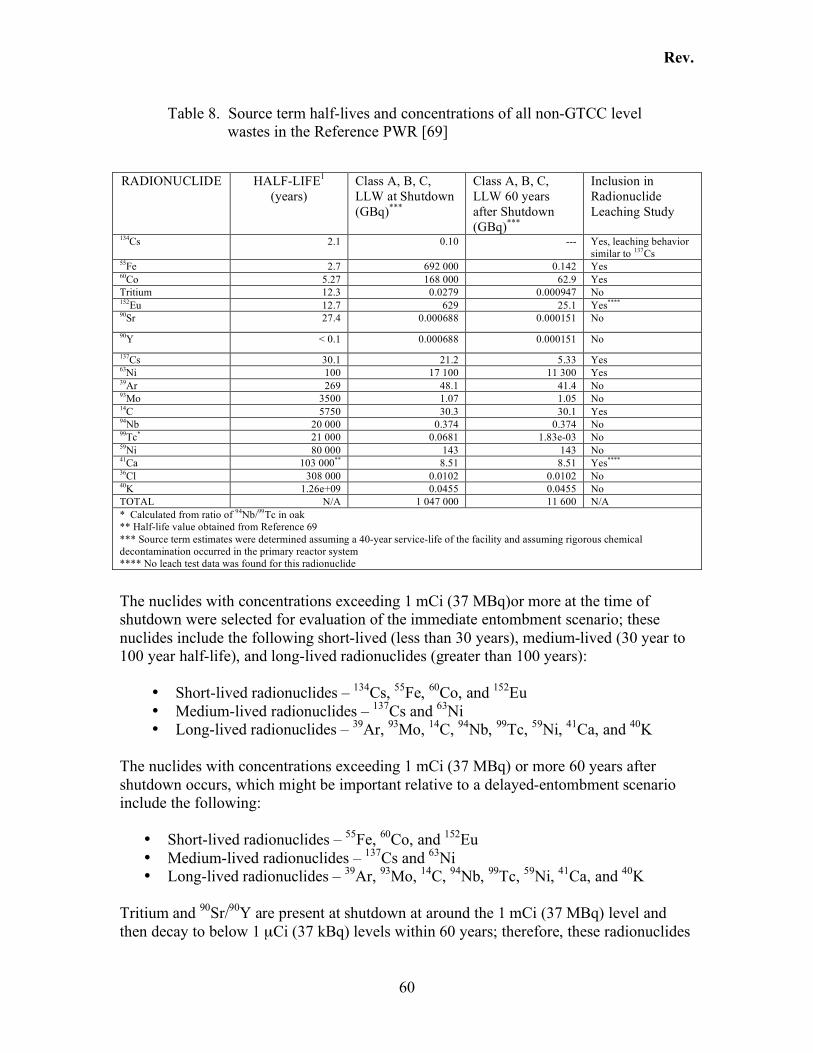
Rev.
60
Table 8. Source term half-lives and concentrations of all non-GTCC level wastes in the Reference PWR [69]
RADIONUCLIDE HALF-LIFE1
(years) Class A, B, C, LLW at Shutdown (GBq)***
Class A, B, C, LLW 60 years after Shutdown (GBq)***
Inclusion in Radionuclide Leaching Study
134Cs 2.1 0.10 --- Yes, leaching behavior similar to 137Cs
55Fe 2.7 692 000 0.142 Yes 60Co 5.27 168 000 62.9 Yes Tritium 12.3 0.0279 0.000947 No 152Eu 12.7 629 25.1 Yes****
90Sr 27.4 0.000688 0.000151 No 90Y < 0.1 0.000688 0.000151 No 137Cs 30.1 21.2 5.33 Yes 63Ni 100 17 100 11 300 Yes 39Ar 269 48.1 41.4 No 93Mo 3500 1.07 1.05 No 14C 5750 30.3 30.1 Yes 94Nb 20 000 0.374 0.374 No 99Tc* 21 000 0.0681 1.83e-03 No 59Ni 80 000 143 143 No 41Ca 103 000** 8.51 8.51 Yes**** 36Cl 308 000 0.0102 0.0102 No 40K 1.26e+09 0.0455 0.0455 No TOTAL N/A 1 047 000 11 600 N/A * Calculated from ratio of 94Nb/99Tc in oak
** Half-life value obtained from Reference 69 *** Source term estimates were determined assuming a 40-year service-life of the facility and assuming rigorous chemical decontamination occurred in the primary reactor system **** No leach test data was found for this radionuclide
The nuclides with concentrations exceeding 1 mCi (37 MBq)or more at the time of shutdown were selected for evaluation of the immediate entombment scenario; these nuclides include the following short-lived (less than 30 years), medium-lived (30 year to 100 year half-life), and long-lived radionuclides (greater than 100 years):
• Short-lived radionuclides – 134Cs, 55Fe, 60Co, and 152Eu • Medium-lived radionuclides – 137Cs and 63Ni • Long-lived radionuclides – 39Ar, 93Mo, 14C, 94Nb, 99Tc, 59Ni, 41Ca, and 40K
The nuclides with concentrations exceeding 1 mCi (37 MBq) or more 60 years after shutdown occurs, which might be important relative to a delayed-entombment scenario include the following:
• Short-lived radionuclides – 55Fe, 60Co, and 152Eu • Medium-lived radionuclides – 137Cs and 63Ni • Long-lived radionuclides – 39Ar, 93Mo, 14C, 94Nb, 99Tc, 59Ni, 41Ca, and 40K
Tritium and 90Sr/90Y are present at shutdown at around the 1 mCi (37 MBq) level and then decay to below 1 µCi (37 kBq) levels within 60 years; therefore, these radionuclides
Rev.
61
will most likely be insignificant in a radionuclide leaching and transport in a delayed entombment scenario. The same is true of 134Cs, which is initially present at about 3 mCi (100 MBq) at shutdown but decays to essentially 0 by the end of the 60-year interval. The long-lived radionuclide concentrations remain nearly unchanged for 60 years after the shutdown of operations and will be persistent for well beyond the defined lifetime of the disposal facility. However, the long-lived radioisotopes 94Nb and 59Ni are generated as a result of neutron irradiation and are physically bound in the carbon steel or steel liner of the reactor vessel. Therefore, it is likely that these radionuclides will only be made available to the cement matrix by corrosion of the steel. Corrosion is highly unlikely unless the steel is subjected to a liquid, other substance, or biological agent that would act to corrode or dissolve the metal. Barring a major natural or man-made disaster, the entombed facility is highly impenetrable and it is unlikely that water or other liquids will reach the metal parts of the reactor vessel to accelerate corrosion. It has been estimated that releases of radionuclides from an entombed steel vessel due to corrosion would reach a maximum rate of 10 mCi (370 MBq) to 15 mCi (560 MBq) per year2. Because the corrosion of metal and transport of radionuclides fixed within the steel inner vessel would have to occur before movement through the cement could take place, the metallurgically-bound long-lived radionuclides 94Nb and 59Ni have not been included in the radionuclide leaching assessment. The radionuclides that were chosen for inclusion in this report are 137Cs, 55Fe, 60Co, 63Ni, 152Eu, 90Sr, 14C. The first five short- and medium-lived isotopes include those radioisotopes that, based on the table above, are the most active non-GTCC radionuclides at shutdown (within 5 years of operation termination), and 60 years after the time of shutdown of operations. 90Sr and 14C were also included in the discussions because there was a significant amount of research regarding the leaching of these two radionuclides, which had implications for the leaching behavior of the other radionuclides included in this report.
4.2 Cement Composition
The chemical and physical properties of cement-based materials and their interactions with the environment are explained in the context of cement chemistry and cement paste formation. The use of the term grout refers to the fluid mix of cement and water that is used to fill empty chambers. The term paste refers to the hardened phase of grout [72]. Furthermore, mixes with sand are called mortar and mixes with coarse aggregate are termed concrete. Because the type of cement known as portland cement has most often been used for waste immobilization applications such as the entombment option discussed here, the terms grout or cement will be used interchangeably and will refer to Type I portland cement, unless otherwise specified.
2 Appendices B and C of SECY-99-187 provide a more complete discussion of the potential for steel degradation in the entombed structure and the likely outcomes.
Rev.
62
Portland cement consists of the following main oxides: lime (CaO), magnesia (MgO), iron (Fe2O3), silica (SiO2), alumina (Al2O3), and sulfate (SO4) (as gypsum). The lime, magnesia, iron, silica, and alumina are crushed, milled, apportioned, and then subjected to a high-temperature kiln (1400 oC to 1650 oC) to create clinker. Portland cement clinker consists of four major phases [73, 75]:
• alite (Ca3SiO5), comprising (50 to 70) % mass fraction • belite (Ca2SiO4), comprising (15 to 30) % mass fraction • aluminate phase (Ca3Al2O6), comprising (5 to 10) % mass fraction • ferrite phase (Ca2AlFeO5), comprising (5 to 15) % mass fraction
After the clinker is removed from the kiln, it is ground and blended with gypsum to delay the setting time [73] in [75]. Several variations of portland cement have been devised and classified by ASTM. These different types of portland cement have been listed in Table 9. The variations have been accomplished by altering the basic formula concentrations, or by incorporating additives into the cement mix. While cement is considered one of the most effective methods for immobilizing radioactive isotopes, the chemical and physical properties of the cement must be carefully designed so that the unique performance objectives for each particular application are met. One of the major components of hydrated cement paste that can affect the long-term stability is the presence of large amounts of calcium hydroxide [Ca(OH)2], also known as portlandite. Portlandite has a high solubility and comprises approximately 20 % (volume fraction) of the paste. Therefore, ordinary portland cement by itself does not always make a good stabilizer as Ca(OH)2 is easily leached. For this reason, formula changes or the addition of supplementary materials such as natural pozzolans or clays should be considered to mitigate leaching of Ca(OH)2 and other potential degradation processes [73, 77]. It should be noted, however, that portlandite in the presence of carbon dioxide reacts to form calcium carbonate, which is highly insoluble and has the potential to complex radionuclides and increase the stability of the paste. See Section 4.3.3 for a full discussion of this process.
4.2.1 Cement Paste Formation
The hydration reactions occur very quickly and exothermically. If the heat given off from these reactions is not dissipated efficiently, it can cause non-uniform heating and cooling, resulting in cracking due to the uneven changes in volume. During the early stages of hydration, the pore fluid pH rises rapidly. The basic pH is caused by the formation of the base compound portlandite [CaOH2] [73, 74]. Hydration reactions then cause the formation of minerals that lead to setting of the cement paste. The compounds formed upon hydration include minerals such as ettringite and calcium silicate hydrate (C-S-H), which primarily provides binding capacity/strength, and portlandite. As the curing time lengthens to one week and then to a few months, the mineral calcium monosulfate replaces ettringite (see Figure 12). The calcium silicate gel and portlandite continue to be formed while calcium aluminoferrite hydrate phase precipitation increases. As the hydrated minerals continue to form throughout the curing process, porosity decreases as reaction products fill the void spaces of the paste. About one year after the
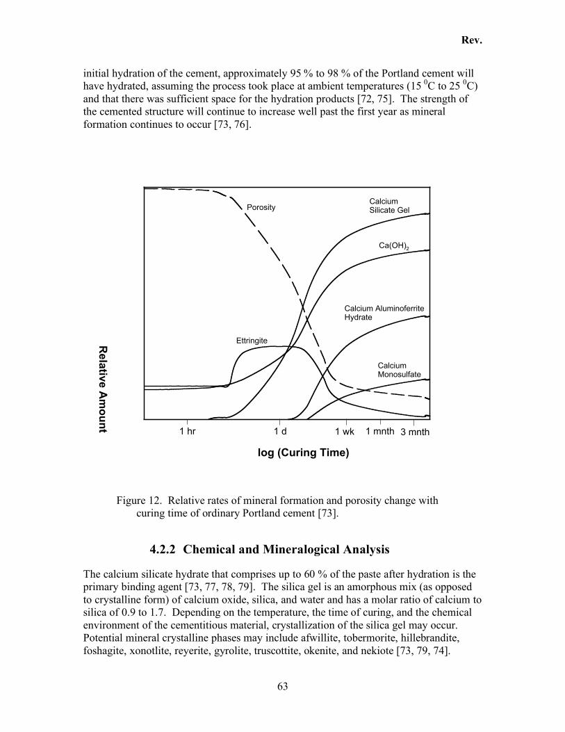
Rev.
63
initial hydration of the cement, approximately 95 % to 98 % of the Portland cement will have hydrated, assuming the process took place at ambient temperatures (15 0C to 25 0C) and that there was sufficient space for the hydration products [72, 75]. The strength of the cemented structure will continue to increase well past the first year as mineral formation continues to occur [73, 76].
1 hr 1 d 1 wk 1 mnth 3 mnth
log (Curing Time)R
ela
tive
Am
ou
nt
CalciumMonosulfate
Ettringite
Ca(OH)2
CalciumSilicate Gel
Calcium AluminoferriteHydrate
Porosity
Figure 12. Relative rates of mineral formation and porosity change with
curing time of ordinary Portland cement [73].
4.2.2 Chemical and Mineralogical Analysis
The calcium silicate hydrate that comprises up to 60 % of the paste after hydration is the primary binding agent [73, 77, 78, 79]. The silica gel is an amorphous mix (as opposed to crystalline form) of calcium oxide, silica, and water and has a molar ratio of calcium to silica of 0.9 to 1.7. Depending on the temperature, the time of curing, and the chemical environment of the cementitious material, crystallization of the silica gel may occur. Potential mineral crystalline phases may include afwillite, tobermorite, hillebrandite, foshagite, xonotlite, reyerite, gyrolite, truscottite, okenite, and nekiote [73, 79, 74].
Rev.
64
Despite this mineralization process, some portion of the silica gel will remain in the cement for long time intervals, maybe even as long as 1500 years or more [73, 80, 81]. This has been demonstrated by the discovery of cement pastes produced by ancient civilizations. Studies of these pastes also indicate that the addition of silica pozzolans increases resistance to natural weathering processes and improves overall durability [80, 81]. It can be deduced from knowledge of the chemical and mineralogical composition, combined with evidence of long-term stability of cementitious materials, that cement paste can maintain structural integrity for long periods of time. However, maintenance of the structural integrity will be compromised upon extensive exposure to paste-degrading solutions such as sulfuric or carbonic acids in water. This topic will be more fully discussed in Section 4.3.
4.2.3 Pore-water Chemistry
Cement paste pore solution is known to be highly alkaline (pH 12 to 13). In general, the high pH of pore solution will reduce the potential for metal corrosion and lower the solubility of some radionuclides, both very beneficial attributes in an entombed disposal facility [73, 82]. While the configuration of an entombed reactor facility is not intended to allow influx of water, either as a by-product of surface water, meteorological (rain, humidity), or groundwater infiltration, a brief discussion of the potential interactions of pore solution with ground water will be provided to assess the potential risks if such a condition occurs. Pore solution composition has the potential to greatly influence the long-term durability of cement paste. In order to evaluate the effects of pore solution chemistry and any potential pore solution reactions that may occur in an entombment scenario, modeling studies based on the thermodynamics of these systems must be evaluated. The thermodynamic modeling is predicated on the following assumptions:
• Those solids predicted by the known chemical reactions represent the main chemical equilibrium reactions for the cement and pore-water interactions. Examples include the calcium-silicate gel, Ca(OH)2, KOH, and NaOH.
• The cement is completely hydrated. • All pore solution/cement mineral reactions have reached chemical equilibrium. • The chemical reactions occur homogeneously throughout the cement and at a
constant rate over time. It is also assumed that the cement continuously re-saturates with water at a constant rate over extended periods of time.
A mixing tank conceptual model is used to simulate the influx and mixing of ground water with the pore solution. Modeling is accomplished by defining an idealized mixture of cement paste having a known mineralogical content, and allowing for equilibration to occur. During equilibration, some minerals dissolve and enter the solution phase while other minerals precipitate according to their stability. The solution is allowed to equilibrate again. This process is referred to as a “water exchange cycle” [83, 84, 85, 78]. After each water exchange cycle, the quantities of minerals precipitated or dissolved are added or subtracted to the quantities of minerals in the initial cement mixture.
Rev.
65
The following is a synopsis of the generalized results from successive water cycle exchanges [73]:
• The initial dissolution of alkali hydroxides (NaOH and KOH) from the cement creates a high pH environment, ranging from 12.5 to 13.5
• Once alkali hydroxides have been removed, the pH level remains high and is controlled by the hydrolysis of portlandite [Ca(OH)2]
• Upon complete dissolution of the portlandite, the pH begins to slowly decrease due mostly to selective dissolution of the calcium silicate gel. The pH declines from 12.5 to about 10.5 [73, 86]. Since the solid matrix of cement is primarily comprised of the calcium silicate gel, the water exchange cycles can continue for a fairly long time with a relatively high pH.
• After the calcium silicate gel is completely dissolved, the pH may decline further, from around 10.5 down to 7.5. If the leachate (ground water or other solution) contains sufficient amounts of carbonate, the equilibrium may become controlled by bicarbonate or calcite [CaCO3] or both.
• Remaining crystalline hydrate phases may continue to provide some buffering of the pH from a range of 11 to 9.5, however the small concentrations of these compounds will eventually be depleted.
• The drop in pH that occurs with the dissolution of the calcium silicate gel phase to a level below 10.5 indicates that complete degradation of the cement form has taken place, unless the presence of secondary minerals such as calcite have sufficient binding ability to maintain the structure.
The use of the water exchange cycle model has allowed scientists to estimate the useful lifetime of cement waste forms. Based on this modeling, it has been estimated that a cement paste lifetime of 1000 years to 100 000 years can be expected, and some predictions have ranged from the thousands to a million year lifetime [73]. These lifetimes are given assuming continuous water exchange takes place at the C-S-H interface. Therefore, it can be assumed that if a cement paste were to remain free from continuous water exposure, and barring other conditions that would exacerbate the degradation of cement paste, these lifetimes are conservative estimates. Other studies indicate, however, that microbial attack on cemented waste forms is unlikely given the high internal pH of cement paste pore solution. High pH environments are generally inimical to biological agents. The risk for biological activity does increase over long time intervals when a lower pH outer layer develops on the cement as a result of carbonation reactions or leaching processes [72].
4.3 Cement Degradation Processes
Entombing nuclear reactor facilities immobilizes radionuclides in three ways: isolation of radionuclides, physical encapsulation, and chemical fixation. In any case, the factors that exacerbate the degradation of cement should be carefully assessed to maximize the immobilization potential of the engineered cement barrier. There are several processes by which the cementitious material can be compromised or degraded. These include
Rev.
66
thermal cycling, physical stress and cracking, contaminant interaction with the cement (chemical reactions), radiation (mainly gas generation problems), microbiological attack, and ground, meteorological, or surface water contact.
4.3.1 Degradation Determination
The leaching potential of radionuclides entombed in a reactor can be accelerated if the cement paste immobilizing those radioactive components is degraded. Degradation can be determined in many ways. One of the ways in which cement integrity is assessed is through the use of compressive strength measurements. Decreases in strength may indicate that some form of deterioration has occurred in the cement structure. Pore solution pH can also be an indication of degradation. Generally, the cement paste is considered completely degraded when the pH of the pore solution drops to around 10.5. The pH drop is indicative of the depletion of the calcium silicate gel that is the primary binding phase of the cement paste, as was discussed in the previous section. The United States Nuclear Regulatory Commission (NRC) has provided a list of durability requirements for Low-Level, Class B and C wastes. These are widely applicable to an entombment scenario and include the following [100]:
• Waste should be in a structure that provides stability for disposal • Waste should contain only minor amounts of drainable liquid, and may not
exceed one percent of the total waste volume (10 CFR 61.56(b)(2) [87]) • The waste should be resistant to degradation caused by radiation effects • The waste should be resistant to biodegradation • The waste should remain stable if exposed to moisture or water after disposal • The waste should be compatible with the solidification (entombment in this case)
medium The following processes define the ways in which cement forms can be degraded and should be evaluated against the criteria listed as durability requirements for Class B and C wastes.
4.3.2 Heat Evolution and Thermal Cycling
The cement hydration that occurs is exothermic. Calorimeter measurements have produced values around 200 kJ/kg in the first 48 h. When the setting time is mostly completed (within about 1 week), the hydration reactions become dominated by diffusion and heat generation slows until 28 d, when further heat of hydration is no longer easily measurable. The heat evolution is not uniform, and heat is not easily dissipated from large monoliths. Consequently, uneven heating and cooling can take place within the same structure, which can lead to thermally induced cracking [73, 76]. Additionally, other extrinsic reactions may be exacerbated by the generation of heat within the cement structure. Actions taken to minimize the effects of thermal cycling include limiting the maximum temperature excursion by employing cement additives (see Section 4.4).
Rev.
67
4.3.3 Carbonation Reactions
Theoretical modeling of the effects of carbonate on cement systems reveal that carbonate concentration plays a major role in affecting the lifetime of the cement and the leachability of radionuclides. This is primarily due to the conversion of portlandite to calcite [73], in [78, 85], as illustrated in equations (2), (3), (4), (5), (6), (7) and (8) below. The significance of calcite formation is two-fold: The first is that calcite formation has the ability to affect the integrity of the cement paste. The determining factor in this case is the pH of the system and is described below in Section 4.3.3.1 and Section 4.3.3.2. Secondly, calcite has the potential to affect the release rate of radionuclides contained in the cement paste pore system. The reasons calcite formation affects radionuclide leach rates are related to the physical/chemical properties of the radionuclides and the reactions they undergo in the cement matrix. Some radionuclides are encapsulated in cement mainly by virtue of adsorption to or encapsulation by the calcium silicate gel and are not complexed by mineral carbonates such as calcite. For these radionuclides, increases in release rates of radionuclides occur as a result of the loss of the C-S-H phase that occurs upon calcite formation. Radionuclides that are precipitated in cements by carbonation reactions have lower leach rates than radionuclides that do not undergo calcium substitution in these reactions3 [73]. This happens as radionuclides, mostly those having similar chemical properties to calcium (with valence states of +2) undergo irreversible substitution reactions with the calcium in calcite. The radionuclides that undergo substitution reactions with calcium are precipitated in carbonate-bearing minerals in cement paste matrices and are increasingly bound to the cement paste by these reactions.
4.3.3.1 Carbonate reactions under moderate pH conditions
The interaction of cementitous systems with water from ground, soil, or atmospheric water can result in the uptake of carbon dioxide (CO2), resulting in the formation of carbonic acid (H2CO3) and bicarbonate (HCO3
-). Carbonic acid can cause the leaching of calcium from portlandite and calcium silicate gel phases and the formation of calcite [73]. If the pH of the system is close to neutral, calcite formation can proceed to cause the production of more acid as the example below shows:
+++!++ HCaCOOHgCOCa 2)( 322
2 (2) In the absence of pH buffering, the system continues to produce acid, causing more calcium leaching, resulting in the degradation of the cement paste pore structure.
4.3.3.2 Carbonate reactions under basic (high pH) conditions
Highly basic conditions, such as those that exist in the pore solution of cement paste, facilitate the uptake of CO2 from the atmosphere, driving the formation of CO3
2- [73] in 3 See Section 4.7 Radionuclide Properties and Leach Characteristics.
Rev.
68
[88]. An experimental investigation into the partitioning of 14C from a resin matrix to a grout [89] in 14C isolation demonstrated this occurrence. The experiment involved loading a resin with carbonate and mixing the resin with grout slurry. The reaction sequences occurred as a result of prevailing basic conditions such as would be expected in a cement paste matrix. In this case, OH- is the dominant anion and readily exchanges with the HCO3
- found in the resin. This exchange continues until the pore water concentrations of HCO3
- reach equilibrium concentrations: !!!!
+"+ 3)()(3 HCOOHOHHCOadad
(3)
The highly basic conditions drive disassociation of bicarbonate ions to carbonate (CO32-)
in the pore solution. Additionally, OH- concentration in the pore solution, as a result of exchange with bicarbonate ions on the resin, causes the dissolution of portlandite, Ca(OH)2, as follows:
!++" OHCaOHCa
s2)( 2
)(2 (4)
The free calcium cations react with the carbonate ions that result from the precipitation of calcium carbonate (calcite):
)(3
2
3
2
sCaCOCOCa !+
"+ (5)
The mineral phases of grout such as portlandite and the C-S-H phases provide a large reservoir of soluble calcium that is available for calcite formation. As calcite continues to precipitate, portlandite continues to dissolve until an almost complete transfer of carbonate ions out of the resin to the cement has occurred.
This sequence of events describes how the carbonate ions (from the resin in this case) can diffuse into the cement matrix and at high concentrations, cause the formation of calcite (CaCO3) and to a smaller extent, magnesium carbonate phases [73]. Carbonation also involves the formation of other mineral phases. Carbon dioxide reacts with the hydration products of cement, such as portlandite (previously discussed), as well as C-S-H, ettringite, and hydrogrossularite phases to produce calcium carbonate, calcium-aluminate, ferric and alumina oxides, and silica gel. A chemical equilibria model determined that the carbonation reactions occur in a progressive order of mineralogical changes as follows [89]:
!
Ca(OH )2(s) + CO2(g ) "CaCO3(s) + #H2O(I )
(portlandite) (calcite)
(6)
!
Ca3 Al 2O6 " 6H2O(s) + 5H2O(I ) + 2CO2(g ) #CaCO3(s) + Ca2 Al2O4(CO3 ) "11H2O(s)
(hydrogrossularite)# (calcite) + (Ca - carboaluminate)
(7)
!
Ca6 Al2O6(SO4 )3 " 32H2O + 6CO2 # 6CaCO3 + 2Al(OH )3(s) + 26H2O(I ) + 3SO4
2$
(ettringite) (calcite) + 6H+
(8)
Rev.
69
The supply of Ca2+ and OH- for the carbonate reactions are obtained from dissolution of portlandite and decomposition of the hydrated silicate phases [90]:
!
xCaO.SiO2(aq) + zH2O " yCa2+
+ 2yOH#
+ ( x # y)CaO.SiO2(aq)
(9)
Decalcification of the C-S-H initially lowers the Ca/Si molar ratio, and ultimately leads to the conversion to highly porous hydrous forms of silica [90]. Continued progressive carbonation of a cement/water system can eventually cause a decrease in pH and a decline in the calcium to silica ratio of the C-S-H gel from approximately 2.0 to less than 0.4 [89]. This can adversely affect leach rates. The rate of carbonation in cement is affected by the cement type, the water to cement ratio, permeability, and porosity of the matrix. It is also affected by temperature, partial pressure of the carbon dioxide, and relative humidity. Carbonation reactions can significantly affect radionuclide release rates and therefore the potential for these to occur needs to be thoroughly investigated as part of any entombment performance assessment.
4.3.4 Sulfate Attack
In a sulfate-attack scenario, sulfate-containing water reacts with cement to produce ettringite ]3633[ 2432 OHCaSOOAlCaO !!! . The formation of ettringite and the addition of sulfate in the form of gypsum provide the hardening agents for the cement. It is during this hardening phase that the cement paste can expand to allow the formation of the voluminous ettringite crystals. Within hours of the initial set time, ettringite begins to convert to calcium monosulfate ]))5.0)((()()([( 242262 SOOHOHOHAlCa [73], which is accompanied by a decrease in molar volume. The cement paste integrity will be unaffected by sulfate conditions if the calcium monosulfate continues to be the dominant sulfate mineral. But if sulfate-containing waters contact the cement paste, the calcium monosulfate and any remaining aluminate can be converted to ettringite. The reaction from monosulfate to ettringite is expansive, thereby causing damage and deterioration of the hydrated cement paste. The expansion of void volume and fracturing of the matrix becomes self-perpetuating as the process allows more exposure of the matrix to the sulfate-water solution. The first stage of this process is controlled by the diffusion rate of sulfate into the cement via miniature cracks and pore volume, with a second stage being controlled by the rate of ettringite formation and spread of cracks within the cement paste [73, 91].
Methods that are effective in decreasing the susceptibility of cement to sulfate attack include: increasing the amount of silica pozzolanic materials (e.g., fly ash, silica fume, blast furnace slag) in the cement formulation to bind calcium, thereby reducing its availability to form ettringite [73, 76, 81, 93]; reducing the quantity of aluminum in the cement formulation to decrease the potential for the formation of ettringite; and entraining air to provide disconnected void spaces where ettringite can grow without creating crystallization pressure.
Rev.
70
4.3.5 Radiolysis
Cementitious materials used to contain low-level wastes, or in this case, entombed structures contaminated with low-level waste, are not likely to undergo significant property changes as a result of radiation. It is possible for higher radiation emissions to affect pore water in cement via radiolysis [73, 72]. It should be expected that these conditions would not occur to a significant extent in an entombment scenario because all of the residual activity will be less than GTCC level. However, performance assessments should thoroughly address the issue of the potential for radiolytic gas formation in an entombed facility given the total inventory of radionuclides. Furthermore, radiolytically generated heat has been known to cause cracking in waste grouts [92]. It was noted in leach tests in Section 4.8.2.1 (137Cs leachability in the presence of kaolinite) that cement waste form compressive strength values decreased upon subjection to gamma ray irradiation by a 60Co source.
4.3.6 Alkali-Aggregate Reactions
Alkali-aggregate reactions fall into two categories: reactions with siliceous aggregates and reactions with carbonate aggregates. These reactions only apply to cementitious materials in which siliceous aggregates were used. In siliceous aggregate reactions involving concretes with low alkali contents, silica may be re-precipitated as calcium silicate gel and may act to increase the strength of the concrete structure. However, for concretes containing large alkali contents, the reactions may cause silica to be readily leached in the presence of moist, high pH conditions (> pH of 12). This is partially due to the large solubility of silica in high pH environments. Silica becomes more soluble under high pH conditions because of the de-protonation of silicic acid (H4SiO4
0), which in turn increases the dissolution of silicic minerals. The alkaline solutes (silicic minerals) can be re-precipitated as alkali silicates, which are expansive and can cause extensive cracking in the concrete [73, 93]. Avoiding siliceous alkali aggregate reaction-induced degradation can be achieved by using a low alkali content in the concrete mix, eliminating the use of water high in potassium or sodium for concrete mixing, and/or adding pozzolanic materials with large amounts of calcium silicates. Carbonate aggregate reactions involve the dissolution of calcium carbonate (CaCO3) found in limestone aggregates. Dissolution of calcium carbonates creates a solution high in calcium cations (Ca2+). If the silica concentration in that solution is such that the calcium precipitates as calcium sulfate (CaSO4, anhydrite, or CaSO4⋅2H2O, gypsum) rather than as calcium silicate gel, mineralogical changes may occur. However, major degradation processes such as cracking will not occur because there will be very little change in the molar volume as a result of calcium sulfate precipitation [73, 76].
Rev.
71
4.3.7 Microbial-Catalyzed Oxidation Reactions
The effects of Thiobacillus bacteria on the integrity of cemented low-level radioactive waste forms were studied in a series of tests [94]. These bacteria obtain energy by oxidizing reduced sulfur to sulfate, with the production of sulfuric acid as a byproduct. Testing revealed that sufficient quantities of reduced sulfur are available in cement to support bacterial survival. It was demonstrated that Thiobacillus could successfully induce a chemical process that resulted in the production of acidic pH values at the surface of the cementitious material. The acid can lead to leaching of calcium from the silicate gel phase of the cement, which reduces the strength and structural integrity of the cement waste form [73, 94]. While Thiobacillus has been identified in soils at various low-level waste sites and appears to be a potential risk for the long-term burial of radioactive cemented waste forms, it needs a more moderate pH and oxygen to survive and, therefore, may or may not pose a degradation risk. Structures under consideration for entombment should be assessed for the development of conditions that would allow proliferation of these bacteria.
4.3.8 Degradation by Corrosion
It has been determined that steel-reinforced mortar and concrete structures are degraded by the presence of chloride solutions. Unlike the other degradation processes discussed, corrosion occurs in the metal components of a cementitious composite structure, and not the cement paste phase itself [73, 76, 95, 96]. Steel is of particular concern in chloride-induced corrosion processes because of its increased susceptibility to such processes. Additionally, it is assumed that there will be some metal reinforcements in the grouting, as well as other metal components within the facility being entombed. The evaluation of the potential for corrosion and, therefore, leaching of radionuclides to occur depends on whether the metal components will in any way be exposed to chloride-containing solutions, or any other conditions that may affect corrosion of metal such as acidic conditions. The major factor for preventing chloride-induced corrosion appears to be the ability to minimize transport of chlorides to the metal components. This is achieved by minimizing contact to chloride-containing solutions, and designing the mortar/concrete mixture to minimize diffusivity and permeability. Without exposure to solutions, metal corrosion rates are minimal [73, 76, 95, 96].
4.4 Cement Performance Enhancement
There are two main ways in which the effects of degradation processes on cement matrices can be minimized. These include cement formulation changes and the inclusion of supplementary additives. Minimization of degradation is important for maintaining the integrity of the engineered barrier and, therefore, reducing the likelihood that leaching
Rev.
72
of radionuclides will occur. A synopsis of the most common formula changes and additives is provided below.
4.4.1 Formula Changes
Formula changes can be quite effective in mitigating undesirable cement characteristics. One such example is the susceptibility of cement paste to sulfate attack. This susceptibility must generally be addressed when it is known that the cement paste will come into contact with ground water [73]. The main difference between ordinary portland cement (Type I) and sulfate-resistant portland cement (Type V) is that the sulfate-resistant cement has a lower concentration of calcium aluminates. Calcium aluminates contribute to the formation of ettringite [73], which leads to degradation of the cement paste. Increased formation of this mineral leads to volume changes within the structure of the cement that lead to cracking and compromised cement integrity. Cements with a lower aluminate content effectively decrease the propensity for cracking. The acceptable amount of calcium aluminate should be measured using XRD [97], as the traditional Bogue estimate is unreliable for this phase. Another formula change is the use of an air entrainment agent. The purpose of air-entrainment is to create small (10 µm to 250 µm) air voids within the pore structure. These admixtures were developed to mitigate the effect of freeze-thaw cycles on concrete. The underlying theory is that the entrained air voids act as “release valves” for the pressures produced as ice forms in the cement paste during freezing. Correspondingly, they may also act to reduce the pressures created during the creation of expansive reaction products such as ettringite, thereby reducing the volume changes within the structure that can cause cracking.
Table 9. Portland cement types and Bogue composition [73, 76].
Chemical Composition6 Type Characteristic SiO2 Al2O3 Fe2O3 CaO MgO SO3
Type I* Normal 20.9 5.2 2.3 64.4 2.8 2.9 Type IA Normal, air-
entrained NA NA NA NA NA NA
Type II Moderate sulfate resistance
21.7 4.7 3.6 63.6 2.9 2.4
Type IIA Moderate sulfate resistance, air-entrained
NA NA NA NA NA NA
Type III High early strength 21.3 5.1 2.3 64.9 3.0 3.1 Type IIIA High early strength,
air-entrained NA NA NA NA NA NA
Type IV Low heat of hydration
24.3 4.3 4.1 62.3 1.8 1.9
Type V High sulfate resistance
25.0 3.4 2.8 64.4 1.9 1.6
* Usually referred to as ordinary portland cement (OPC) NA – Not Available
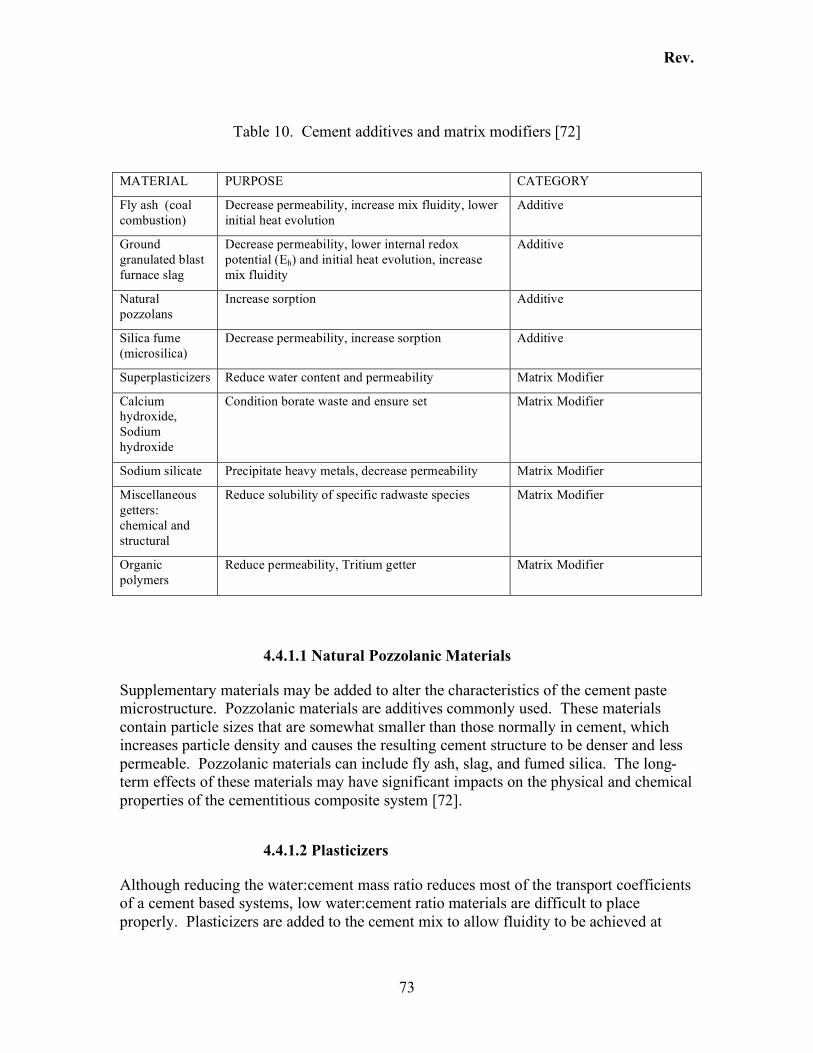
Rev.
73
Table 10. Cement additives and matrix modifiers [72]
MATERIAL PURPOSE CATEGORY
Fly ash (coal combustion)
Decrease permeability, increase mix fluidity, lower initial heat evolution
Additive
Ground granulated blast furnace slag
Decrease permeability, lower internal redox potential (Eh) and initial heat evolution, increase mix fluidity
Additive
Natural pozzolans
Increase sorption Additive
Silica fume (microsilica)
Decrease permeability, increase sorption Additive
Superplasticizers Reduce water content and permeability Matrix Modifier
Calcium hydroxide, Sodium hydroxide
Condition borate waste and ensure set Matrix Modifier
Sodium silicate Precipitate heavy metals, decrease permeability Matrix Modifier
Miscellaneous getters: chemical and structural
Reduce solubility of specific radwaste species Matrix Modifier
Organic polymers
Reduce permeability, Tritium getter Matrix Modifier
4.4.1.1 Natural Pozzolanic Materials
Supplementary materials may be added to alter the characteristics of the cement paste microstructure. Pozzolanic materials are additives commonly used. These materials contain particle sizes that are somewhat smaller than those normally in cement, which increases particle density and causes the resulting cement structure to be denser and less permeable. Pozzolanic materials can include fly ash, slag, and fumed silica. The long-term effects of these materials may have significant impacts on the physical and chemical properties of the cementitious composite system [72].
4.4.1.2 Plasticizers
Although reducing the water:cement mass ratio reduces most of the transport coefficients of a cement based systems, low water:cement ratio materials are difficult to place properly. Plasticizers are added to the cement mix to allow fluidity to be achieved at
Rev.
74
lower water content. However, the long-term effects on cement stability and contaminant fixation of this group of additives are not fully known [72].
4.4.1.3 Conditioners
Calcium hydroxide and sodium hydroxide are used to neutralize acidic materials and to condition borates. These conditioning reactions are not completely understood. Sodium silicate precipitates metallic ions from solution but these processes are not fully known [72].
4.4.1.4 Getters
Getters have been employed to condition certain species such as iodine or tritium. Zeolitic getters have been successfully used to reduce cesium leaching from cementitious materials. However, the large amounts of zeolite required to retard cesium leaching tends to compromise the compressive strength and increase the water demand of the cement system [72].
4.4.1.5 Organic Polymers
Organic polymers have been used in attempts to further immobilize certain species of contaminants. Long-term evaluations have revealed that the immobilization effectiveness of polymer compounds is not reliable under environmental degradation or radiation conditions. However, they have been proven to enhance tritium immobilization [72].
4.5 Cement Performance in Relation To Radionuclide Immobilization
The use of grouting in the decommissioning of nuclear power plants is intended to isolate radioactive contamination by physically encapsulating or chemically binding radionuclides. The leaching of radionuclides immobilized by cementitious materials can occur via diffusion or convection and is affected by a variety of factors. The factors that affect the performance of cement-based mortars in immobilizing radionuclides can be grouped into three main categories. They include factors related to the physical nature of the cement structure, the chemical structure and interactions with the cementitious material, and the conditions of the environment in which the radionuclides are entombed. As these factors are evaluated, a list of parameters used to assess the integrity of the cement form can be defined.
4.5.1 Physical Properties Affecting Grout Performance
Physical encapsulation as a means of immobilizing radionuclides takes on a very important role for those isotopes that are not chemically fixed by the grouting material.
Rev.
75
Mass transport properties of cement paste play an important role in the ability of the grout to act as an effective barrier to the release of radionuclides. Therefore, engineered barriers must have low transport properties to prohibit the influx of solutions from atmospheric or environmental seepage conditions that have the potential to leach radionuclides. The structural/physical properties that are important to the ability of cement paste to seal radionuclide contaminants include the following: Pore Structure: Capillary and C-S-H pore structure determine the rate and extent of water movement during hydration. The pore structure also dictates the long-term density and permeability of grout. Reductions in porosity, the average pore size, and pore connectivity in cement-based materials decrease the overall permeability of the system. Hydraulic Conductivity: How readily water can move through the cement paste affects the rate of water or aqueous phase movement through the grout, thereby reducing the rate that radionuclides can be transported. Cure Time: Proper curing, by providing sufficient water during early stages of hydration, is critical to the formation of C-S-H. The physical and chemical structure of the cement as well as the physical and chemical properties of the radionuclides will determine the extent of mobility, and, therefore, the distribution of these radionuclides in cement paste. Distribution of Contaminants: The manner in which contaminants are distributed in the final waste form will contribute to the time required for radionuclides to be transported out of the structure. Additionally, concentration gradients at the grout/wall interface will affect uptake rates, equilibrium balances, and interactions within the cement paste. Calcium to Silica Ratio: Large calcium to silica ratios allow greater anionic sorption to occur and can buffer alkali aggregate reactions4. Conversely, low calcium to silica ratios favor the uptake of positively charged cations such as Co2+ or Ni2+ (chemical fixation). Water to Cement (w/c) Mass Ratio: The water:cement (w/c) mass ratio affects the amount of pore water volume and, therefore, the density and the permeability of cement paste. Under normal curing practice, the external surface will take in water, causing the w/c to increase, resulting in a layer of paste with a higher porosity [98]. The higher porosity in the external layer of the cementitious grout partially accounts for initial fast leaching rates of radionuclides. Mineral Surface Charge: The surface charge on C-S-H and other minerals present in the cement paste pore structure may favor adsorption of some radionuclides that do not otherwise react or chemically bind with cement pastes. Discussion: The extent to which cement paste provides a physical/chemical barrier to transport is largely determined by its pore structure. Cement paste that has a dense matrix has less 4 See Section 4.3.6 for a more detailed discussion of these processes
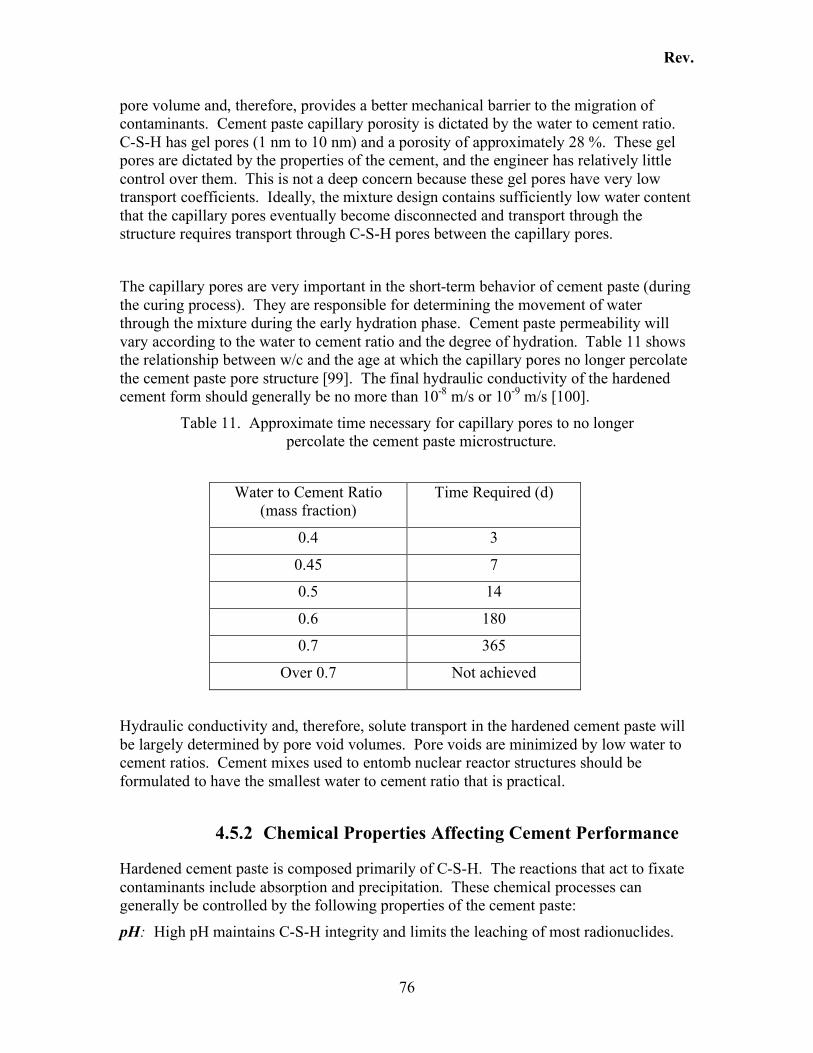
Rev.
76
pore volume and, therefore, provides a better mechanical barrier to the migration of contaminants. Cement paste capillary porosity is dictated by the water to cement ratio. C-S-H has gel pores (1 nm to 10 nm) and a porosity of approximately 28 %. These gel pores are dictated by the properties of the cement, and the engineer has relatively little control over them. This is not a deep concern because these gel pores have very low transport coefficients. Ideally, the mixture design contains sufficiently low water content that the capillary pores eventually become disconnected and transport through the structure requires transport through C-S-H pores between the capillary pores.
The capillary pores are very important in the short-term behavior of cement paste (during the curing process). They are responsible for determining the movement of water through the mixture during the early hydration phase. Cement paste permeability will vary according to the water to cement ratio and the degree of hydration. Table 11 shows the relationship between w/c and the age at which the capillary pores no longer percolate the cement paste pore structure [99]. The final hydraulic conductivity of the hardened cement form should generally be no more than 10-8 m/s or 10-9 m/s [100].
Table 11. Approximate time necessary for capillary pores to no longer percolate the cement paste microstructure.
Water to Cement Ratio (mass fraction)
Time Required (d)
0.4 3
0.45 7
0.5 14
0.6 180
0.7 365
Over 0.7 Not achieved
Hydraulic conductivity and, therefore, solute transport in the hardened cement paste will be largely determined by pore void volumes. Pore voids are minimized by low water to cement ratios. Cement mixes used to entomb nuclear reactor structures should be formulated to have the smallest water to cement ratio that is practical.
4.5.2 Chemical Properties Affecting Cement Performance
Hardened cement paste is composed primarily of C-S-H. The reactions that act to fixate contaminants include absorption and precipitation. These chemical processes can generally be controlled by the following properties of the cement paste:
pH: High pH maintains C-S-H integrity and limits the leaching of most radionuclides.
Rev.
77
Cement Constituents5: Cement hydration induces high pH, causing the binding of many radionuclides. Changes in the cement constituents can affect which contaminants are effectively bound. Use of Additives: Additives can alter which contaminants are immobilized by the cement paste microstructure. Pore Solution Chemistry6: Pore solution exchange with external water has the potential to cause changes in the equilibrium concentrations of ionic species. This can result in mineral dissolution or precipitation, pH alteration (water cycling usually causes dissolution of C-S-H phases which decreases pH). Decrease of pH leads to disintegration of the cement paste matrix.
Discussion: Together, the C-S-H gel and the Ca(OH)2 comprise more than 80 % of the cement paste volume and, therefore, control the chemical properties of the aqueous phase of portland cement. This is due to the fact that these compounds buffer the calcium concentration and contribute to the high pH. C-S-H is the principal buffering agent that maintains a high pH for the very long-term and is largely responsible for the stability of the cement form5. C-S-H is a colloidal, amorphous compound with a high surface area, and at temperatures below 100 oC has good ion-absorption and cation-exchange properties. C-S-H therefore has the ability to immobilize metal ions by addition and substitution reactions as follows [100]:
HSCMMHSC !!!"+!!
Addition Reaction
(10)
+
+!!!"+!!2
CaHSCMMHSC
Substitution Reaction
(11)
As stated in the previous section, the lower the calcium to silica ratio in the C-S-H, the more cation incorporation can occur. Addition of certain pozzolanic materials can be used in these circumstances to free Ca(OH)2, lower the calcium/silicate ratio without compromising the integrity of the matrix, and effectively increase the metal fixation ability of the cement. The discussion of cement additives is provided elsewhere [100].
Another chemical property of cement that may influence long-term behavior and interactions with radionuclides is the internal redox potential, Eh. Because cement paste contains an aqueous phase, the Eh is a measurable parameter that can influence the interactions of cement paste phases with other compounds. Cement pastes tend to have a
5 See Section 4.2, including the chemical/mineralogical composition 6 Discussed in Section 4.2.3.
Rev.
78
very poor buffering capacity, also known as the poising capacity, which means that the Eh is easily influenced by outside factors. This is important because electropositive metals can react with cements to effectively lower the Eh to a potential that effects the liberation of hydrogen ions (H+). Liberation of hydrogen ions will affect the pH of the system and, therefore, the stability of the cement [72].
4.5.3 Environmental Influences in Cement Performance
There are a number of factors in the environment of any waste repository that will influence the performance of the waste disposal system. The factors listed here are those that have specifically been addressed by current leach tests or have otherwise been mentioned in literature reviews conducted in support of radionuclide leaching investigations. There may be additional factors that are not listed here but should be considered based on each unique repository environment. Those conditions that have the potential to significantly affect the performance of radionuclide immobilization in a cement matrix include the following:
• Presence of liquid (water or other solution) in the repository • Volume and rate of influx of liquid into the repository • Chemical composition of the liquid (leachant), i.e. whether the liquid is
groundwater, or seawater, or some other solution • Temperature of the environment (to include indigenous conditions as well as
artificial conditions such as temperature fluxes due to the heat of hydration given off during initial curing of the cement)
• Chemical and physical nature of the radionuclides • Radiation effects such as radiolysis or radiolytically generated heat • Presence of CO2 in atmosphere, or dissolved in solution can affect radionuclide
release rates as a result of carbonation reactions (see section 4.3.3) • Chemical composition of waste, e.g., whether other contaminants exist such as
sulfate that have the potential to affect radionuclide leach rates from cement • Microbiological agent presence • pH of the environment or surfaces being encapsulated by cement
4.5.4 Cement Grout Integrity Assessment
Cement grout performance can be assessed for each unique disposal environments and set of contaminants. Generally, this is best accomplished by conducting lab-scale surrogate testing with progression to full-scale waste form testing. The tests should provide a measure of whether the radionuclide immobilization strategy (in this case, entombment) will meet a set of performance objectives. Specific criteria that can be measured to give an assessment of cement grout performance include the following:
• Density and porosity of the cement grout • Visual inspection, e.g. cement grout is free of cracks and crumbling, and no
visible ‘bleed’ water
Rev.
79
• Compressive strength • pH of the surface of the cement grout • Leach rates of contaminants of concern determined by testing
4.6 Leaching Tests
The majority of the research to date on the leachability of radionuclides from cementitious materials have been conducted under the assumption that radioactively-contaminated liquid, residues, or ion-exchange resins would be incorporated into the mixture design. Entombment presents a different scenario whereby radioactive components are not added to the mixture, but are immobilized by means of employing the cement grout as a physical barrier. The effectiveness of the cement paste in immobilizing radionuclides will depend upon several factors, including the amount of uptake of radionuclides, the transport and surface complexing mechanisms that will occur within the paste, and the ability of the paste to provide an impervious barrier to those radionuclides that can be isolated by the cement paste microstructure. Therefore, the results of existing leaching tests, with the exception of the 14C study entitled “Cement-Based Engineered Barriers for 14C Isolation” referenced in Section 4.8.1.7, may be used as guides when considering the effectiveness of isolating radionuclides using entombment, but may not completely correlate. It is assumed that existing radionuclide leaching test data provides conservative estimates of leach fractions of radionuclides immobilized by means of an engineered cement-based barrier. One reason this can be assumed is that radionuclides, to a large extent, would not be distributed uniformly throughout the structure as in situations where waste streams are incorporated into cementitious mixes. While the initial pouring of cement-based grout into the nuclear power plant may transport and mix some of the residual radionuclides, the large percentage of radionuclides will probably still be found adhered to the interior walls of the existing structures. Therefore, water, air, or other materials that contact the exterior surfaces of the grout would not affect the leaching of radionuclide contaminants without significant transport of those radionuclides into the core of the cement paste matrix and/or degradation of the grout. Furthermore, tests conducted at the Idaho National Engineering Laboratory (INEEL) on the effect of waste form size on the leachability of radionuclides contained in cementitious materials indicate that leach-testing on small-scale waste form specimens as specified in ANSI 16.1 [19] will result in conservative estimates of long-term releases of radionuclides from full-scale waste forms. This report also concludes that use of short-term leach tests such as those prescribed by ANSI 16.1 [19] will also conservatively predict long-term releases of radionuclides from cement paste matrices because release rates and effective diffusivities are cumulative and decrease with time [98].
4.6.1 Diffusion Coefficients and Leach Indices
The ANSI/ANS-16.102003 [19] leach test is the regulatory test procedure used throughout the world for radioactive wastes. The general procedure involves the use of a right-circular cylinder sample with deionized water as the leachant. The test is conducted
Rev.
80
for 90 d, with leachant replenishment at the following hours: 2, 7, 24, 48, 72, 96, 120, 456, 1128, and 2136. For this procedure, the diffusion coefficient is defined as:
!
D =
an
A0
("t )n
#
$
% % % %
&
'
( ( ( (
2
2
V
S
#
$ % &
' ( nT
n
)
(12)
where: D is the effective diffusion coefficient an is the contaminant mass loss during leaching interval n A0 is the initial mass of contaminant in the specimen V is the specimen volume S is the specimen surface area (
!
" t )n is the duration of the nth leaching interval Tn is the mean time of the nth leaching interval The definition of the leachability index L is as follow:
)log(eDL != (13)
The leachability index is expressed as the logarithm of the reciprocal effective diffusion (solid) coefficient. The United States Nuclear Regulatory Commission (NRC) requires that test procedures developed to demonstrate the leachability of waste forms conform to the ANSI procedure and that the tests be conducted for a minimum of 90 d to establish a true leachability index. The required leachant in this test is deionized water. However, it is stated that other leachants should be used to confirm the solidification agent’s leach resistance under other conditions (e.g., sea water). The main purpose is to find a leachant with the most aggressive leaching capability and provide data for the leach rate for any given compound with that leachate. The complete set of requirements for this test can be found in NRC’s “Technical Position On Waste Form” [101] document and will not be fully discussed here. As a result of leach testing, leachability indices that quantify the relative ability for a radionuclide to be leached can be calculated. For any given compound, the lower the leach index, the higher the leach rate. A leachability index of 6 or greater is required for the solidified waste form to be considered an acceptable disposal method for that particular contaminant [101].
4.6.2 Relative Leachability of Select Radionuclides
The following sections detail literature data for leach testing conducted on cementitious materials for the purposes of determining radionuclide leachability tendencies and rates.
Rev.
81
There were three main studies that reported relative leachabilities for a set of radionuclides included in each study’s respective leach tests. The radionuclides are presented in order of most easily leached radionuclide to least easily leached radionuclide. Following this, the individual radionuclide properties and unique leach characteristics will be presented, and then a general summary of leach test studies that were found in the literature will be given. 1st Major Study, conducted to determine the leaching of radionuclides from cement composites incorporating evaporator concentrates at a pressurized water reactor (PWR) [95]:
3H > 137Cs > 90Sr > 60Co > 144Ce
2nd Major Study, conducted to determine the desorption kinetics of radionuclides fixed in cement paste matrices [89]:
134Cs > 131I > 85Sr > 14C > 60Co
3rd Major Study, conducted to determine the leachability of chelated ion-exchange resins solidified in cement paste or cement paste made with fly ash [84]:
55Fe > 137Cs > 60Co > 63Ni > 90Sr - Cement matrix only7 63Ni > 60Co > 55Fe >> 137Cs – Cement and fly ash matrix8
4.7 Radionuclide Properties and Leach Characteristics
There are three main classifications into which radionuclides can be grouped based on their chemical behavior in a cement paste matrix. The classification [102] is as follows:
• Class 1 - (primarily physically encapsulated): Radionuclides not susceptible to hydrolysis reactions in grout (unhardened cement) when pH approaches 12. Includes 137Cs (included in study), 51Cr(VI), 131I, and 3H. This causes these nuclides to tend to be mobile in cement paste and have higher leachability potentials.
• Class 2 - (chemical fixation): Radionuclides not subject to hydrolysis, form insoluble complexes such as carbonates in cement matrices. Includes 90Sr, 140Ba, and 14C.
• Class 3 - (chemical fixation): Nuclides that undergo hydrolysis in grouts to form insoluble hydroxides. Includes 60Co, 54Mn, and 144Ce.
7 This order of leachability established for Ordinary Portland Cement without additives. 241Pu was also reported but not included because this radionuclide was not included in other discussions; however 241Pu was reported to have the highest LI and therefore had the smallest leach potential. 8 90Sr cumulative fraction released was greater than 20 %. Therefore, the effective diffusivity and LI could not be calculated.
Rev.
82
In general, for all three of these classes, leaching rates of radionuclides are retarded by the high-pH conditions found in cement paste pore solution. The reasons for this phenomenon are as follows. First, positively charged ionic radionuclide species are more readily adsorbed by high-pH cement materials because of the negative charges created at the surface by the high pH environment (physical encapsulation). Secondly, the solubility of many compounds that complex radionuclides are reduced by high-pH conditions. The high pH causes these compounds to precipitate and form complexes in the cement paste microstructure (chemical fixation) that effectively reduces the radionuclide leachability [74, 86, 103, 104]. Third, high-pH conditions favor the stability of the C-S-H gel, the primary binding agent of the cement paste [73]. Furthermore, the following considerations must be accounted for when assessing the ability of radionuclides to be immobilized in an entombment scenario:
� The initial contact of the grout material with the walls of the facility being entombed may allow some of the surface radionuclides to be incorporated into the cement paste matrix itself, but will not incorporate all of the contaminants. Some radionuclides will be adsorbed or encapsulated by the cement paste, while others will chemically bind to the components of the cement paste matrix.
� Contaminants fixed within the metal structures (such as the reactor vessel) must first be leached from the metal matrix and then be transported or leached through the cement paste matrix. The combination of radionuclide fixation in metal and physical binding by cement paste should provide a double isolation and therefore greater immobilization potential
The leaching process itself can generally only be initiated as a result of contact of the solid material with a solution or degradation agent. Therefore, the main radionuclide release risks are exposure of the inside of the entombed facility to an aqueous solution, or degradation of the cement matrix itself followed by contact with the environment (soils or water). The extent to which the grouting material will contact soils or water during the life-time of the structure in any given entombment scenario must also be addressed. Each radionuclide discussed below will contain a listing of Effective Diffusion Coefficients ( effD ) and Leach Indices (LI) ranges, as available in literature based on leach tests performed on cementitious materials. Each value range reported by different research groups has been notated. Not all leach tests were performed under the exact same conditions, which will account for some variability in the resulting effD values. Except as noted, the values presented below were obtained from leach tests that were performed under conditions similar to those specified in the ANSI 16.1 [19] leach test procedure. The cement used in these tests was ordinary portland cement, with sample sizes measuring approximately 20 mm x 20 mm x 20 mm that were cured for 28 d under ambient (room temperature) conditions. The cement paste samples were exposed to deionized water leachant or seawater leachant, with the leachate solution being replaced at specified intervals over a period of approximately (60 to 90) d. Exceptions to these standard procedures are noted below.
Rev.
83
4.7.1 137Cs 137Cs is a man-made isotope and is generated in large quantities as a high-yield fission product in nuclear reactor fuel elements. 137Cs has a half-life of 30.2 y and decays by beta emission to 137Ba and then by gamma ray emission. The specific activity is high for this isotope at 87 Ci/g (3.2 TBq). 137Cs is found in large quantities within the irradiated reactor fuel assemblies. In general, 137Cs is reported to have a high sorptive capacity in sediment, especially at low concentrations and in the presence of pH greater than 4.0 [105]. However, cesium is one of the most mobile nuclides in a water-saturated cement paste matrix, which makes leaching tests even more important for determining immobilization potentials of cesium [106]. This is mainly because cesium does not interact chemically with the cement paste matrix to form complexes and remains available to diffuse and move throughout the matrix.
effD (cm2/d) , deionized water: 4.3x10⁻⁶ [102]; 4.30x10⁻² to 4.55x10⁻² [107]9; 1.07x10⁻⁴- 2.81x10⁻⁴ [108]; 4.6x10⁻⁷ to 5.7x10⁻⁸ [109]
effD (cm2/d) , sea water: 5.2x10⁻⁶ [102]; 2.3x10⁻⁴ to 2.64x10⁻⁴ [108] Leach Index Range, deionized water: 8.55 to 9.025 [108]
Leach Index Range, sea water: 8.555 to 8.5887 [108] Leach Index Range with use of additives: 8.2 to 11.6, 10.3 to 11.1 [110]
4.7.2 55Fe 55Fe decays by x-ray and auger electron emissions and has a half life of 2.7 years. External radiation from 55Fe is low energy and generally does not present a large external exposure hazard. There are not many data available on the leaching of 55Fe presumably because of the low exposure risk posed by this radionuclide. However, one major study included 55Fe in the leach tests and therefore the Leach Indices for this isotope in portland cement, and portland cement mixed with fly ash (LI range with use of additives) have been listed. The LI of 55Fe was actually lowered by the addition of fly ash material, again demonstrating the importance of conducting leach testing for all radionuclides and pre-determined parameters for any given situation.
effD (cm2/d) , deionized water: None reported.
effD (cm2/d) , sea water: None reported. Leach Index Range, deionized water: 14.9 to 16.1 [111] 10 Leach Index Range, sea water: None reported
Leach Index Range with use of additives: 10.9 to 14.6 [111] 11
9 effD obtained from an average of calculated fast and slow diffusion rates, based leaching of 134Cs
10 Leach test conducted on ion-exchange resins containing a mixture of radionuclides and complexing agents solidified in unmodified Portland Type I cement
Rev.
84
4.7.3 60Co 60Co is generated by the neutron activation of 59Co in nuclear reactors. Like 137Cs, 60Co is found in high concentration in the cladding of irradiated reactor fuel assemblies. 60Co has a half-life of 5.27 years and decays by beta emission and gamma ray emission to 60Ni. It has a high specific activity at about 1100 Ci/g (4.1 TBq). 60Co is often present as a divalent cation in subsurface sediments and is strongly adsorbed onto the surface of clay minerals and sediments. It has been shown that dilute acid or chelating compounds such as ethylenediaminetetraacetic acid (EDTA) decrease cobalt adsorption. With respect to cobalt in the environment, it is primarily immobile as it becomes fixed in soil, so its migration is very limited [105]. Leach tests conducted on cemented waste forms containing ion-exchange resins indicate that 60Co tends to be less leachable from cement paste than most other radionuclides. This has been explained by the finding that Co+2, with its valence state of a positive +2 charge appears to react with the portlandite [Ca(OH)2] or Ca-O bonds to replace calcium.
4.7.4 152Eu and 154Eu 154Eu is a byproduct of the activation of 153Eu and is a fission product. Even though 154Eu is not found in high concentrations as is 137Cs, it is found in irradiated fuel. 154Eu has a half-life of 8.59 years and decays by beta particles to 154Gd. It also gives off gamma rays. 152Eu decays by electron capture and positron emission to 152Sm, and by beta emission to 152Gd and has a half-life of 13.5 years. 152Eu also emits gamma rays [105]. Very little data exists on the leachability of these isotopes. Consequently, more work will need to be done to validate grouting as an effective immobilization technique for 152Eu and 154Eu.
4.7.5 90Sr 90Sr has a half-life of 20 years0 and is a high-yield fission product. The decay pattern is emission of beta particles to 90Y with a half-life of 64 h, and then decay to 90Zr. The beta emissions are very high energy (up to 2.2 MeV) and give off a characteristic Bremsstrahlung low-energy continuum of gamma rays. One unique property of 90Sr is that the decay of this isotope generates more heat than other nuclides due to the release of high-energy beta particles in the decay of 90Y [105]. This may have implication to the stability of the cement paste structure and therefore the leaching potential of other radionuclides. Strontium is a divalent cation (Sr2+) that behaves much like calcium. It is soluble in water and forms an ionic bond with elements that are negatively charged. Strontium tends to adsorb onto sediment or clay particles and can replace Ca2+ in CaCO3. Since strontium reacts readily with calcium carbonate, cement chemistry would lend itself to the immobilization of this isotope, especially in the presence of high pH. 11 Leach test conducted on ion exchange resins containing a mixture of radionuclides and complexing agents were solidified in a mix of 80% by weight Portland Type I cement and 20 wt% fly ash with a low calcium content.
Rev.
85
4.7.6 63Ni 63Ni has a half-life of 100 years and decays by beta emission to 63Cu. 63Ni does not emit any gamma rays and has a maximum beta emission of 65.9 keV. The specific activity is 2190 GBq/g [105]. A study conducted at the Idaho National Engineering and Environmental Laboratory (INEEL) concluded that transition metal radionuclides, including 55Fe, 60Co, and 63Ni, behaved similarly in leach tests. All three radionuclides have valence states of 2+ and 3+ and are believed to form complexes with cement compounds. It was also reported in this study that calcium (Ca2+) was irreversibly replaced by both Co2+ and Ni2+, which was inferred from the breakdown of Ca-O bonds in the cement paste mineral structure [84]. Because specific studies aimed at determining the leaching rates of 63Ni immobilized by a cementitious barrier have not been conducted, or were not found in the literature search, these data would need to be provided. effD deionized water: None reported.
effD seawater: None reported. Leach Index Range, deionized water: 7.1 to 11.1 12 Leach Index Range, seawater: None reported
Leach Index Range with use of additives: 13.5 to 15.9 13
4.7.7 14C 14C is produced in nuclear reactors mainly by neutron activation of 14N (alpha and proton emission), 13C (neutron and gamma emission), and 17O (neutron and alpha emission), which are found in the fuel and the coolant/moderator. 14C is one of the highest risk radionuclides from a disposal standpoint for two main reasons. The first is its long half-life of 5730 years. The second is that it has a high rate of migration in the environment and it easily assimilates into biological systems. The form in which 14C is found varies according to the type of reactor and process that generated it. For pressurized water reactors (PWR), 14C is discharged primarily in the form of gases such as 14CH4 (methane), 14C2H6 and other hydrocarbon gases, with only 10 % to 26 % of the 14C being discharged as carbon dioxide (14CO2). The gaseous discharge of 14C from boiling water reactors (BWR) consists of 95 % 14CO2 and 5 % hydrocarbon gases. 14C generally exists in a volatile form, but also exists in wastes generated at nuclear power facilities. The overall leach rate for 14C is low and variable with time.
12 Leach test conducted on ion-exchange resins containing a mixture of radionuclides and complexing agents solidified in unmodified Portland Type I cement 13 Leach test conducted on ion exchange resins containing a mixture of radionuclides and complexing agents were solidified in a mix of 80 % (mass fraction) Portland Type I cement with 20 % (mass fraction) fly ash with a low calcium content.
Rev.
86
Because the leach rate of 14C is variable, the leaching rate of 14C cannot be described by ionic-transport models using diffusion alone, but must be determined by the use of solution compositions, pH and solid phase precipitate parameters [98]. For environments in which carbon dioxide is available, 14C leach rates are remarkably low. It was determined that 14C initially readily leaches from the surface layers of cement, but as concentrations of calcium and carbon dioxide exceed the solubility product of CaCO3, calcium carbonate precipitation occurs which leads to a decrease in carbon dioxide and calcium. As the leachate becomes saturated with calcium carbonate, the pH increases. When the pH approaches 12.5, the 14C in the calcium carbonate most likely also is adsorbed onto the surface of colloidal particles, further retarding the leaching of 14C [98]. While carbonation initially drives the pH upwards, reactions demonstrate that continued carbonation causes mineralogical changes that further alter the cement structure, mineralogically and chemically. See Section 4.3.3 for a complete illustration of these reactions. Because 14C is incorporated into the cement paste in the form of calcium carbonate or calcite, the 14C release characteristics are largely dictated by the presence of calcite. Under static or low-flow conditions, the C-S-H phase and portlandite dominates the chemical environment of the cement by keeping the pH high and the solubility low. As long as the pH of the cement system remains high, the rate of calcite and therefore 14C release is reported to be extremely low [89, 98]. One of the main ways in which 14C may be released is through the dissolution of calcite. Moderate pH values such as those that occur upon exposure of the cement paste to large volumes and high flow rates of leachate solutions, facilitate the release of calcite and therefore the release of 14C. Therefore, in the absence of high flow rates of leachate solutions, cement paste is deemed to be an effective barrier to the release of this radionuclide [89].
4.8 Leaching Studies
4.8.1 Leaching from Cement Paste
There have been several studies on the leaching behavior of radionuclides from cemented forms. The main results and conclusions from these studies are listed below.
4.8.1.1 Leaching of 3H, 137Cs, 90Sr, 60Co, and 144Ce From a Cement-Based Composite
The leaching behavior of a cement-based composite that incorporated evaporator concentrates from a pressurized water reactor from a nuclear power plant were evaluated using the International Atomic Energy Agency leach test [102]. The parameters tested were the waste-cement weight ratio, temperature of the leachate, and the curing time of the cement samples. The wastes contained boric acid, which is known to retard cement hydration. Mixes with 8:1 cement to vermiculite mass ratios were used. The
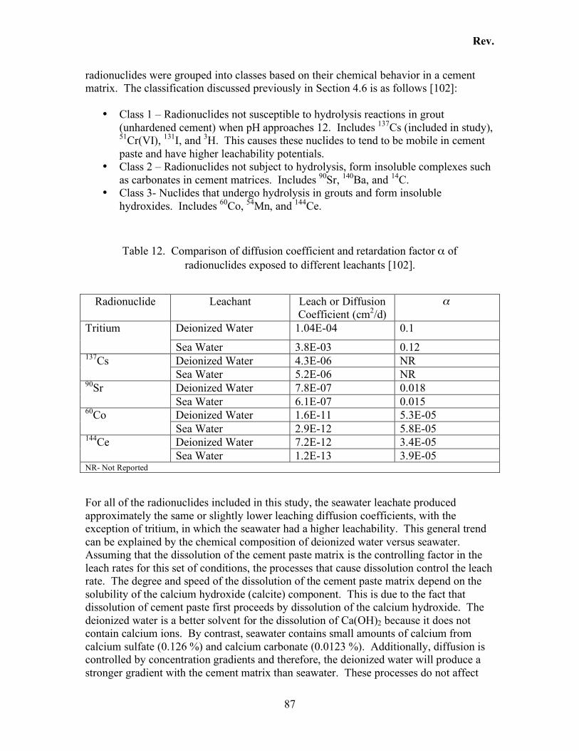
Rev.
87
radionuclides were grouped into classes based on their chemical behavior in a cement matrix. The classification discussed previously in Section 4.6 is as follows [102]:
• Class 1 – Radionuclides not susceptible to hydrolysis reactions in grout (unhardened cement) when pH approaches 12. Includes 137Cs (included in study), 51Cr(VI), 131I, and 3H. This causes these nuclides to tend to be mobile in cement paste and have higher leachability potentials.
• Class 2 – Radionuclides not subject to hydrolysis, form insoluble complexes such as carbonates in cement matrices. Includes 90Sr, 140Ba, and 14C.
• Class 3- Nuclides that undergo hydrolysis in grouts and form insoluble hydroxides. Includes 60Co, 54Mn, and 144Ce.
Table 12. Comparison of diffusion coefficient and retardation factor α of radionuclides exposed to different leachants [102].
Radionuclide Leachant Leach or Diffusion Coefficient (cm2/d)
!
Deionized Water 1.04E-04 0.1 Tritium
Sea Water 3.8E-03 0.12 Deionized Water 4.3E-06 NR 137Cs Sea Water 5.2E-06 NR Deionized Water 7.8E-07 0.018 90Sr Sea Water 6.1E-07 0.015 Deionized Water 1.6E-11 5.3E-05 60Co Sea Water 2.9E-12 5.8E-05 Deionized Water 7.2E-12 3.4E-05 144Ce Sea Water 1.2E-13 3.9E-05
NR- Not Reported For all of the radionuclides included in this study, the seawater leachate produced approximately the same or slightly lower leaching diffusion coefficients, with the exception of tritium, in which the seawater had a higher leachability. This general trend can be explained by the chemical composition of deionized water versus seawater. Assuming that the dissolution of the cement paste matrix is the controlling factor in the leach rates for this set of conditions, the processes that cause dissolution control the leach rate. The degree and speed of the dissolution of the cement paste matrix depend on the solubility of the calcium hydroxide (calcite) component. This is due to the fact that dissolution of cement paste first proceeds by dissolution of the calcium hydroxide. The deionized water is a better solvent for the dissolution of Ca(OH)2 because it does not contain calcium ions. By contrast, seawater contains small amounts of calcium from calcium sulfate (0.126 %) and calcium carbonate (0.0123 %). Additionally, diffusion is controlled by concentration gradients and therefore, the deionized water will produce a stronger gradient with the cement matrix than seawater. These processes do not affect
Rev.
88
tritium because it is not susceptible to the hydrolysis reactions that can complex radionuclides into the calcite and therefore the cement structure. The study [102] contained a large amount of data, not all of which have been tabulated here. However, a summary of the results show a general decrease in leachability starting with the most easily leached radionuclide, tritium, and progressing to the least leached radionuclide as follows: 3H > 137Cs > 90Sr > 60Co > 144Ce. As the water/cement ratio and leachant temperature increased and the curing time decreased, leaching of 3H and 90Sr increased. The leaching rates for 137Cs, 60Co, and 144Ce did not change much with the water/cement ratio or curing time, but increased as the leachant temperature increased. The test results show that leaching is a result of complex interactions and radionuclide properties. The study concludes that experimental data is needed to characterize leaching potentials [102].
4.8.1.2 Results Reported by the Bhabha Atomic Research Center [107]
These leach tests were conducted solely in support of developing desorption kinetics of radionuclides that were fixed in an ordinary portland cement paste matrix. Leach tests were conducted using the International Organization for Standardization (ISO) method, which is very similar to the ANSI 16.1 [19] method. The isotopes of interest in this study included 134Cs, 131I, 85Sr, 14C, and 60Co. Results were not reported for 60Co because the leach test results did not yield significant leaching values over the 60 d the test was conducted. This was determined to be largely due to the chemical interaction of cobalt with the cement paste. Results that were obtained for 131I are included in spond to the effective weights. Table 13 below but are not included in the discussion because iodine was not identified as a target nuclide in a Light Water Reactor (see Section 4.1.3). Leach Mechanisms: The results from the leach tests and mathematical models developed to simulate leach tests indicate that various radionuclides have differential leach rates according to their desorption behavior. This is explained in part by the fact that some radionuclides exist dispersively (physical encapsulation) in the cement paste, and some are chemically bonded to the matrix. Desorption occurs as soluble materials within the cement paste are subjected to water which facilitates the movement of those materials through the cement paste matrix. Radionuclides such as cesium exist in ionic form and therefore leach out from the cement paste to the surrounding water by diffusion. Radionuclides that have smaller leach rates are those that are fixed by cement hydrates and are only released via the dissolution of the cement paste matrix itself. spond to the effective weights. Table 13 shows diffusion coefficients in a cement-based waste form taken from a series of leaching tests [106] for 134Cs, 90Sr, and 14C. The tests suggested that there was an
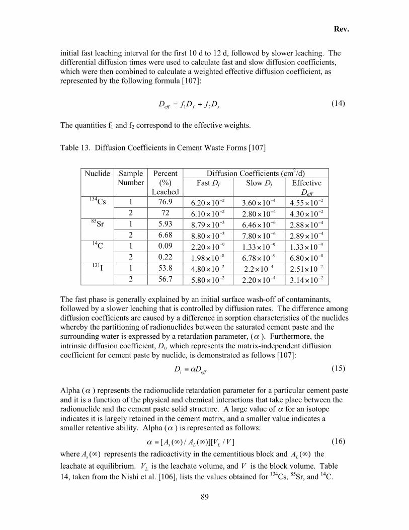
Rev.
89
initial fast leaching interval for the first 10 d to 12 d, followed by slower leaching. The differential diffusion times were used to calculate fast and slow diffusion coefficients, which were then combined to calculate a weighted effective diffusion coefficient, as represented by the following formula [107]:
sfeff DfDfD21
+= (14) The quantities f1 and f2 correspond to the effective weights. Table 13. Diffusion Coefficients in Cement Waste Forms [107]
Diffusion Coefficients (cm2/d) Nuclide Sample Number
Percent (%)
Leached Fast Df Slow Df Effective
Deff 1 76.9 2
1020.6!
" 41060.3
!" 2
1055.4!
" 134Cs 2 72 2
1010.6!
" 41080.2
!" 2
1030.4!
" 1 5.93 3
1079.8!
" 61046.6
!" 4
1088.2!
" 85Sr 2 6.68 3
1080.8!
" 61080.7
!" 4
1089.2!
" 1 0.09 9
1020.2!
" 91033.1
!" 9
1033.1!
" 14C 2 0.22 8
1098.1!
" 91078.6
!" 8
1080.6!
" 1 53.8 2
1080.4!
" 4102.2
!" 2
1051.2!
" 131I
2 56.7 21080.5
!" 4
1020.2!
" 21014.3
!"
The fast phase is generally explained by an initial surface wash-off of contaminants, followed by a slower leaching that is controlled by diffusion rates. The difference among diffusion coefficients are caused by a difference in sorption characteristics of the nuclides whereby the partitioning of radionuclides between the saturated cement paste and the surrounding water is expressed by a retardation parameter, (! ). Furthermore, the intrinsic diffusion coefficient, Di, which represents the matrix-independent diffusion coefficient for cement paste by nuclide, is demonstrated as follows [107]:
effi DD != (15) Alpha (! ) represents the radionuclide retardation parameter for a particular cement paste and it is a function of the physical and chemical interactions that take place between the radionuclide and the cement paste solid structure. A large value of ! for an isotope indicates it is largely retained in the cement matrix, and a smaller value indicates a smaller retentive ability. Alpha (! ) is represented as follows:
]/)][(/)([ VVAALLs
!!=" (16) where )(!
sA represents the radioactivity in the cementitious block and )(!
LA the
leachate at equilibrium. LV is the leachate volume, and V is the block volume. Table
14, taken from the Nishi et al. [106], lists the values obtained for 134Cs, 85Sr, and 14C.
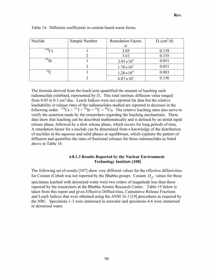
Rev.
90
Table 14. Diffusion coefficients in cement-based waste forms.
Nuclide Sample Number Retardation Factor, !
Di (cm2/d)
1 3.05 0.139 134Cs 2 3.61 0.155 1 2
1001.2 ! 0.051 85Sr 2 2
1078.1 ! 0.051 1 4
1028.1 ! 0.083 14C 2 3
1007.6 ! 0.156 The formula derived from the leach tests quantified the amount of leaching each radionuclide exhibited, represented by Di. This total intrinsic diffusion value ranged from 0.05 to 0.3 cm2/day. Leach Indices were not reported for data but the relative leachability or release rates of the radionuclides studied are reported to decrease in the following order: 134Cs > 131I > 85Sr > 14C > 60Co. The relative leaching rates also serve to verify the assertion made by the researchers regarding the leaching mechanisms. These data show that leaching can be described mathematically and is defined by an initial rapid release phase, followed by a slow release phase, which occurs for long periods of time. A retardation factor for a nuclide can be determined from a knowledge of the distribution of nuclides in the aqueous and solid phases at equilibrium, which explains the pattern of diffusion and quantifies the rates of fractional releases for these radionuclides as listed above in Table 14.
4.8.1.3 Results Reported by the Nuclear Environment Technology Institute [108]
The following set of results [107] show very different values for the effective diffusivities for Cesium (Cobalt was not reported by the Bhabha group). Cesium effD values for those specimens leached with deionized water were two orders of magnitude less than those reported by the researchers at the Bhabha Atomic Research Center. Table 15 below is taken from this report and gives Effective Diffusivities, Cumulative Release Fractions and Leach Indices that were obtained using the ANSI 16.1 [19] procedures as required by the NRC. Specimens 1-3 were immersed in seawater and specimens 4-6 were immersed in deionized water.
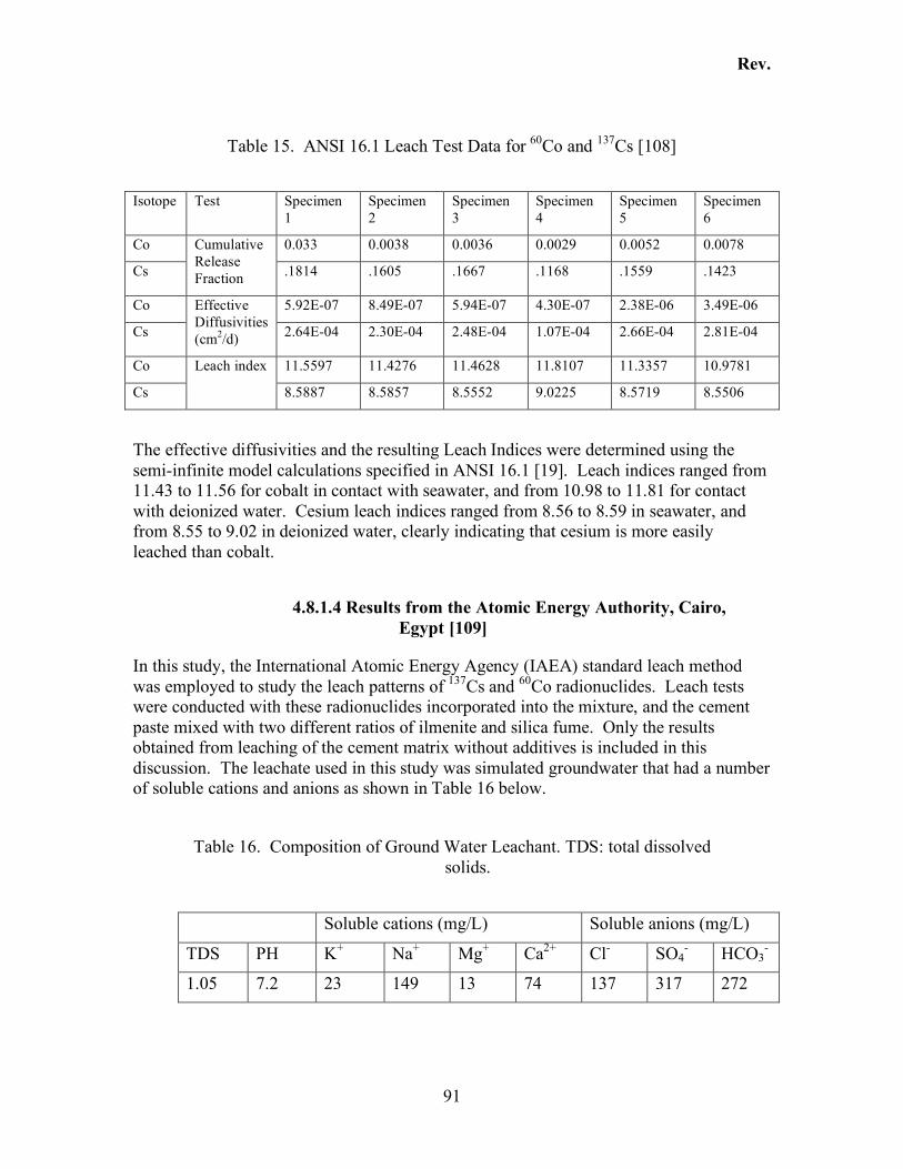
Rev.
91
Table 15. ANSI 16.1 Leach Test Data for 60Co and 137Cs [108]
Isotope Test Specimen 1
Specimen 2
Specimen 3
Specimen 4
Specimen 5
Specimen 6
Co 0.033 0.0038 0.0036 0.0029 0.0052 0.0078
Cs
Cumulative Release Fraction .1814 .1605 .1667 .1168 .1559 .1423
Co 5.92E-07 8.49E-07 5.94E-07 4.30E-07 2.38E-06 3.49E-06
Cs
Effective Diffusivities (cm2/d) 2.64E-04 2.30E-04 2.48E-04 1.07E-04 2.66E-04 2.81E-04
Co 11.5597 11.4276 11.4628 11.8107 11.3357 10.9781
Cs
Leach index
8.5887 8.5857 8.5552 9.0225 8.5719 8.5506
The effective diffusivities and the resulting Leach Indices were determined using the semi-infinite model calculations specified in ANSI 16.1 [19]. Leach indices ranged from 11.43 to 11.56 for cobalt in contact with seawater, and from 10.98 to 11.81 for contact with deionized water. Cesium leach indices ranged from 8.56 to 8.59 in seawater, and from 8.55 to 9.02 in deionized water, clearly indicating that cesium is more easily leached than cobalt.
4.8.1.4 Results from the Atomic Energy Authority, Cairo, Egypt [109]
In this study, the International Atomic Energy Agency (IAEA) standard leach method was employed to study the leach patterns of 137Cs and 60Co radionuclides. Leach tests were conducted with these radionuclides incorporated into the mixture, and the cement paste mixed with two different ratios of ilmenite and silica fume. Only the results obtained from leaching of the cement matrix without additives is included in this discussion. The leachate used in this study was simulated groundwater that had a number of soluble cations and anions as shown in Table 16 below.
Table 16. Composition of Ground Water Leachant. TDS: total dissolved
solids.
Soluble cations (mg/L) Soluble anions (mg/L)
TDS PH K+ Na+ Mg+ Ca2+ Cl- SO4- HCO3
-
1.05 7.2 23 149 13 74 137 317 272
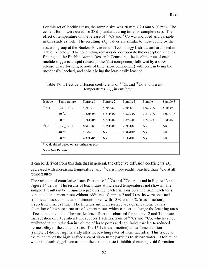
Rev.
92
For this set of leaching tests, the sample size was 20 mm x 20 mm x 20 mm. The cement forms were cured for 28 d (standard curing time for complete set). The effect of temperature on the release of 137Cs and 60Co was included as a variable in this study as well. The resulting effD values are similar to those found by the research group at the Nuclear Environment Technology Institute and are listed in Table 17, below. The concluding remarks do corroborate the desorption kinetics findings of the Bhabha Atomic Research Centre that the leaching rate of each nuclide suggests a rapid release phase (fast component) followed by a slow release phase for long periods of time (slow component) with cesium being the most easily leached, and cobalt being the least easily leached.
Table 17. Effective diffusion coefficients of 137Cs and 60Co at different
temperatures, Deff in cm2/day
Isotope Temperature Sample 1 Sample 2 Sample 3 Sample 4 Sample 5
(25 +3) oC 4.6E-07 5.7E-08 2.6E-07 1.02E-07 5.4E-08
40 oC 1.52E-06 6.27E-07 4.32E-07 2.87E-07 2.02E-07
137Cs
60 oC 1.26E-05 6.72E-07 1.89E-06 1.22E-06 8.3E-07
(25 +3) oC 6.9E-08 3.75E-08 2.2E-08 NR NR
40 oC 5E-07 NR 1.8E-08* NR NR
60Co
60 oC 4.37E-06 NR 1.1E-08 NR NR
* Calculated based on an Arrhenius plot
NR – Not Reported
It can be derived from this data that in general, the effective diffusion coefficients effD decreased with increasing temperature, and 137Cs is more readily leached than 60Co at all temperatures. The variation of cumulative leach fractions of 137Cs and 60Co are found in Figure 13 and Figure 14 below. The results of leach rates at increased temperatures not shown. The sample 1 results in both figures represents the leach fractions obtained from leach tests conducted on cement paste without additives. Samples 2 and 3 results were obtained from leach tests conducted on cement mixed with 10 % and 15 % (mass fraction), respectively, silica fume. The fineness and high surface area of silica fume causes alteration of the pore structure of cement paste, which can act to change the leaching rates of cesium and cobalt. The smaller leach fractions obtained for samples 2 and 3 indicate that addition of 10 % silica fume reduces leach fractions of 137Cs and 60Co, which can be attributed to the reduction in volume of large pores and capillaries that led to reduced permeability of the cement paste. The 15 % (mass fraction) silica fume addition (sample 3) did not significantly alter the leaching rates of these nuclides. This is due to the tendency of the high surface area of silica fume particles to absorb water. If too much water is adsorbed, gel formation in the cement paste is inhibited causing void formation
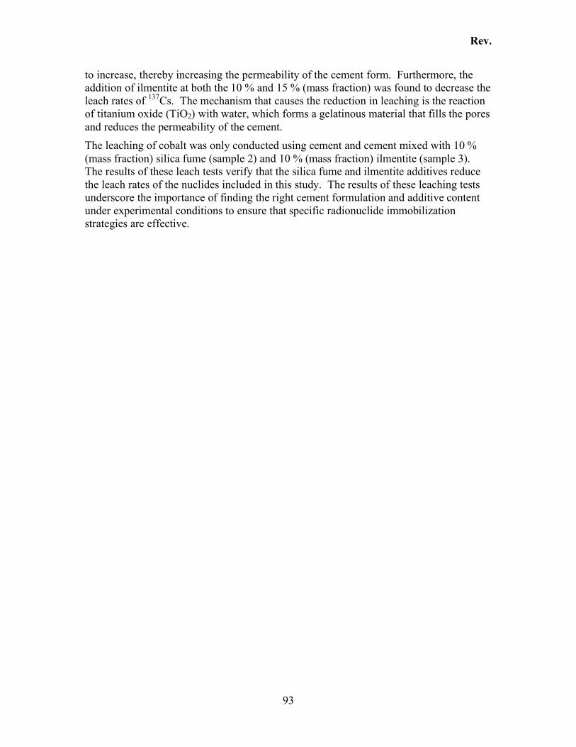
Rev.
93
to increase, thereby increasing the permeability of the cement form. Furthermore, the addition of ilmentite at both the 10 % and 15 % (mass fraction) was found to decrease the leach rates of 137Cs. The mechanism that causes the reduction in leaching is the reaction of titanium oxide (TiO2) with water, which forms a gelatinous material that fills the pores and reduces the permeability of the cement. The leaching of cobalt was only conducted using cement and cement mixed with 10 % (mass fraction) silica fume (sample 2) and 10 % (mass fraction) ilmentite (sample 3). The results of these leach tests verify that the silica fume and ilmentite additives reduce the leach rates of the nuclides included in this study. The results of these leaching tests underscore the importance of finding the right cement formulation and additive content under experimental conditions to ensure that specific radionuclide immobilization strategies are effective.
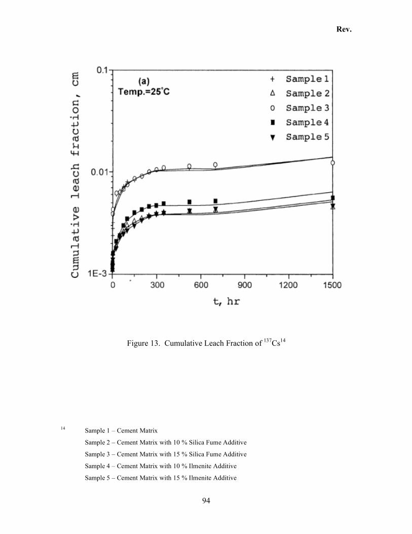
Rev.
94
Figure 13. Cumulative Leach Fraction of 137Cs14
14 Sample 1 – Cement Matrix
Sample 2 – Cement Matrix with 10 % Silica Fume Additive
Sample 3 – Cement Matrix with 15 % Silica Fume Additive
Sample 4 – Cement Matrix with 10 % Ilmenite Additive
Sample 5 – Cement Matrix with 15 % Ilmenite Additive
Rev.
95
Figure 14. Cumulative Leach Fraction of 60Co 15
4.8.1.5 Leachability as a Function of Cement Stability [112]
The first set of leaching test results were conducted to determine whether nuclear fuel reprocessing plant waste streams could be encapsulated in cement in conformance with NRC guidelines. The stability guideline used to make this determination was leachability. The leach testing was performed using the ANSI method 16.1 [19]. In this test, three 25.4 mm diameter cement slugs containing radioactively contaminated (137Cs used) liquid waste were cured for 28 d using a previously determined optimum cement formula. The test was conducted over 91 d, using deionized water as the leachate. After the initial removal of mobile surface contamination, the leach rate was commensurate with a diffusion mechanism. Additionally the conditions of the uniform mass were determined to approximate that of a semi-infinite medium and therefore the mass transport equations used to calculate the effective diffusivity and Leach Indices are the same as were presented earlier in Section 4.6.1, Diffusion Coefficients and Leach Indices. The data obtained from these tests were determined to not have an excessive bias or spread and the cement paste did not show any signs of physical deterioration throughout the test. The waste samples all had Leach Index values for 137Cs greater than six,
15 Sample 1 – Cement Matrix
Sample 2 – Cement Matrix with 10 % Silica Fume Additive
Sample 3 – Cement Matrix with 10 % Ilmentite Additive
Rev.
96
ranging from 6.6 to 7.02 with values calculated after 5 d and at the end of 91 d of continuous leaching.
4.8.1.6 Cesium and Strontium Leach Test Results from the Material Research Laboratory [113]
Results from the Pennsylvania State University Materials Research Laboratory leach tests were collected at varying intervals, up to a one year time interval. The leachate was distilled water. Three types of cement mineral were treated with cesium- or strontium-containing solutions: 3CaO(SiO2), 3CaO(Al2O3), and
!
" -2(CaO)SiO2. The mineral/radionuclide mixture was then leached. Neither the cesium nor the strontium was immobilized until the test was repeated with CO2 being bubbled through the cement mineral suspension. When carbon dioxide was added to the environment, cesium was precipitated as Cs2CO3 and strontium was precipitated as SrCO3. The resulting uptake of cesium was measured under these conditions to be anywhere from 62 % to 91 %, depending on the cement mineral while the resulting uptake of strontium was measured under these conditions to be 100 %. The precipitation of calcium carbonate from cement is commonly known to occur in the presence of atmospheric carbon dioxide. The conclusion of this group of researchers was that cements or cementitious materials immobilize cesium, strontium, (and barium) through the formation of carbonates with strontium being more strongly complexed and therefore less leached. The research from this study indicates that cesium can form carbonate complexes to some extent. This was not suggested in any of the other studies thus far. While it is unclear to what extent cesium reacts with carbon dioxide to become fixated in the carbonate minerals of cement paste, this research does validate the fact that strontium is less easily leached from cement paste because of complex carbonation reactions than cesium.
4.8.1.7 Cement-Based Engineered Barriers For 14C Isolation [89]
Experiments were conducted as part of the Ontario Hydro Reactor Waste Disposal Program [89] in order to evaluate carbon dioxide interactions with grout and determine what effects the CO2 had on radiocarbon immobilization. This research is the only work done in which radionuclide isolation in the context of a cement-based engineered barrier was investigated. The experiments focused on determining how carbonation in the cement paste progressed and how it affected the change in material characteristics of the cement paste matrix and the way in which material characteristic changes affected carbonated cement paste transport properties and long-term stability of the cement paste. The experiments demonstrated redistribution and partitioning of 14C in a cement-based system and the way in which carbonation affects that distribution. Carbonation reaction kinetics were also observed. The study also investigated the effects of static or low-flow leachate rates compared to high-flow leachate rates in relation to cement stability and leachability of 14C. Leach tests were conducted on samples of portland cement (with a
Rev.
97
water/cement mass ratio of 0.4) using water at room temperature (23 oC) under variable leachant flow rates. The following conclusions were drawn from these experiments: 14C Partitioning in a Resin/Grout System: High pH conditions found in cement pastes were observed to facilitate the stoichiometric transfer of carbonate ions in resin to the cement, thereby driving formation of calcite (See the reactions illustrations in Section 4.3.3). Leaching Behavior of 14C in a Cemented Waste Form High leachant flows over 220 d resulted in a release of 14C of less than 2 % of the initial amount. The pH with the high-flow leachate rate decreased until it reached about 7.5, which promoted substantial 14C release. For low-flow or static flow leachate rates, the chemistry of the cement system remained alkaline and no 14C was found in the leachates. This process is explained by the fact that all 14C can be assumed to be present as CaCO3 as a result of carbonation reactions. Calcium carbonate is not soluble in a solution saturated with portlandite and therefore as long as the pH remains high, portlandite will control the solubility equilibrium, minimizing calcite dissolution (see equations in section 4.3.3). 14C Attenuation in Cement-based Backfill The objective of this set of tests was to determine the viability of cement-based backfill materials to act as a geo-chemical sink for 14C. The reaction of carbon dioxide with the main hydrate calcium-containing components of concretes results in the generation of calcite, silica gel, and ferric and alumina oxides. Progressive carbonation proceeds as calcium to silica ratios in the C-S-H phase decrease. Carbonation Reaction Kinetics The rate of carbonation in solid cement paste is affected by material properties such as the water/cement ratio, porosity, permeability, cement type, and environmental conditions, e.g. temperature, relative humidity, and the partial pressure concentration of CO2. Stage 1 of carbonation occurs as carbon dioxide diffuses into the pores of the cement paste where it dissolves and travels through water films on grain surfaces in the cement paste. This phase is completed within 15 min and comes to completion when water film concentrations of carbon dioxide are in equilibrium with ambient carbon dioxide pressure. Stage 2 results in hydroxyl ions from mineral components of the cement paste diffusing out into the water films. During this phase, pores become blocked and carbon dioxide stops migrating through the cement matrix. Carbonation rates of reaction are enhanced by the presence of water because water facilitates the reaction of hydroxyl ions (OH-) at the gas (CO2)/water interface and the resulting formation of carbonate-mineral formation. The amount of water available to facilitate these reactions can be influenced by environmental humidity. It was found that maximum carbonation rates occurred in atmospheres of 50 % humidity. It was stated in this report that a 50 % relative humidity is believed to be low enough to maintain an open pore network for the CO2 to be transported through the matrix, but high enough to allow water to act as a leaching and precipitating medium.
Rev.
98
Carbonation and Permeability Tests These experiments showed the that carbonation of a grout system resulted in a reduction of water permeability from 10-16 m2 to 10-21 m2 in one set of tests, and from 3x10-18 m2 to 8x10-21 m2 in a second set of tests. Carbonation-Induced Changes in Material Properties A progressive reduction from the sample exterior to the sample interior was noted for both permeability and porosity. Porosity and permeability values ranged from 22 % and 1.3 x 10⁻¹⁶ m2, respectively, in the least carbonated part of the sample, to 17 % and 3.9 x 10⁻¹⁷ m2 in the most carbonated part of the core, which was the area immediately adjacent to the carbon dioxide injection hole. X-ray diffraction and infrared analyses of the samples showed a progressive increasing amount in calcite content, with correlating decreases in portlandite concentrations. The analyses also reveal that the C-S-H phase was transformed into silica gel. Diffusion rates of tritiated water were also observed in these tests. The rates under saturated conditions were 1.8 x 10⁻¹² m2/s in grout that was not subjected to carbon dioxide, and 0.62 x 10⁻¹² m2/s for carbonated grout. It can be deduced that these results support the conclusion that carbonation reactions reduce the porosity, and therefore permeability of cement grouts. Conclusions The conclusion of this study was that cementitious engineered barriers are effective in isolating 14C under the following conditions: low groundwater flow rates, alkaline conditions (pH > 10.5), and availability of carbon dioxide [89]. Given these conditions, it can be expected that 14C will remain immobile for long intervals of time equivalent to the amount needed for 14C to decay to much safer levels [98].
4.8.1.8 Leachability of Chelated ion-exchange resins [111]
Ion-exchange resins loaded with radionuclides, transition metals, and organic chelating compounds were solidified in either Ordinary Portland Type I cement, or in a cement mix of 80 % (mass fraction) portland cement and 20 % (mass fraction) fly ash. The ANSI 16.1 [19] leach test was used to perform the leach tests. The leachate used was distilled water and leaching tests were performed over a 90 d interval at room temperature. Sample size was approximately 50 mm x 100 mm. Results from the leach tests demonstrated the following relative leachabilities: 55Fe > 137Cs > 60Co > 63Ni > 90Sr 16 in cement matrix only; and 63Ni>60Co>55Fe>137Cs 17 in the cement and fly ash mix. The study stated that it is well known that adding a pozzolan additive such as fly ash to the cement mix can reduce the permeability of the concrete significantly. The results of the study showed that releases of radionuclides were usually higher from the waste forms stabilized with unmodified Portland cement compared to the waste forms solidified using 16 This order of leachability established for Ordinary Portland Cement without additives. 241Pu was also reported but not included because this radionuclide was not included in other discussions; however 241Pu was reported to have the highest LI and therefore had the smallest leach potential. 17 90Sr cumulative fraction released was greater than 20 %, therefore the effective diffusivity and LI could not be calculated.
Rev.
99
the Portland Type I cement and fly ash mix. It was noted that the presence of chelating agents in the cement waste forms did not significantly increase leach rates for five of the six waste forms tested for 55Fe, 60Co, or 63Ni. Table 18 below taken from this report, lists the Leachability Indexes for the radionuclides included in the study.
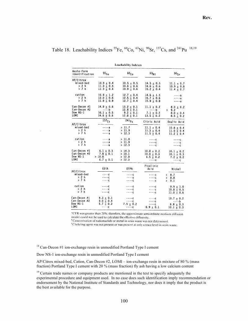
Rev.
100
Table 18. Leachability Indices 55Fe, 60Co, 63Ni, 90Sr, 137Cs, and 241Pu 18,19
18 Can-Decon #1 ion-exchange resin in unmodified Portland Type I cement
Dow NS-1 ion-exchange resin in unmodified Portland Type I cement
AP/Citrox mixed-bed, Cation, Can-Decon #2, LOMI – ion-exchange resin in mixture of 80 % (mass fraction) Portland Type I cement with 20 % (mass fraction) fly ash having a low calcium content 19 Certain trade names or company products are mentioned in the text to specify adequately the experimental procedure and equipment used. In no case does such identification imply recommendation or endorsement by the National Institute of Standards and Technology, nor does it imply that the product is the best available for the purpose.
Rev.
101
4.8.2 Leaching From Cement With Additives
The following leach tests present data collected on the leachability of the radionuclides included in consideration for an entombment scenario from cementitious matrices that have had additives included in the cement mix.
4.8.2.1 137Cs Leachability in the presence of Kaolinite [114]
Studies have shown that silicate clays increase the adsorption properties of cement paste and therefore decrease the leaching rates of radioactive elements. In a series of tests, the effectiveness of kaolinite in reducing the leachability of 137Cs and 60Co were studied under a variety of conditions. Variables in the experiments included the addition of various chemicals (H2SO4, HNO4, NaOH, Na2SO4, citric acid, boric acid, oxalic acid, EDTA, etc.) to the cement mix, and the irradiation of the cement by a 60Co source. Cement cubes measuring 20 mm x 20 mm x 20 mm were subjected to leaching. Results included the following:
• Addition of kaolinite to the cement mix decreased the compressive strength but was effective in reducing the amounts of 60Co and 137Cs that were released. The samples that were cured for 28 d showed a decrease in compressive strength of the kaolinite mixture over the cement and water mixture.
• Addition of the various chemicals to the cement-kaolinite mix caused a decrease in the density of the cement and the compressive strength, but the absorption and porosity of the matrix increased as the concentration of chemicals increased. The decrease in compressive strength was caused by the interaction between the chemicals and the calcium ions of the C-S-H gel or the Ca(OH)2.
• Compressive strength and density values for the kaolinite-cement mixtures also decreased as the absorbed gamma dose increased.
The report concluded that a 7.5 % kaolinite-cement mixture improved the conditioning properties of cement and is an acceptable matrix for immobilizing low-level radioactive wastes.
4.8.2.2 137Cs leachability from cementitious mixes containing kaolin clay [115]
Another report published by the Turkish Atomic Energy Authority [115] reports that a 5 % (mass fraction) kaolin clay cement mixture reduces leaching of these radionuclides by about 50 % over ordinary portland cement. The report concludes that a 5 % (mass fraction) kaolin-cement mixture decreases leaching rates without compromising the strength of the cement structure [115]. The generalized conclusion that kaolinite effectively reduces the leach rate of cesium (134Cs and 137Cs), as well as 60Co, is supported by several other leaching studies [106].
Rev.
102
4.8.2.3 Leach tests of sludges from cement mixed with various additives [110]
Leach tests were conducted on mixed waste sludges produced at the Oak Ridge National Laboratory (ORNL). These sludges are different in their composition and nature than what would be expected during the entombment of a nuclear power plant structure. Nonetheless, some generally relevant information can be ascertained from these tests. The main differences are that the sludges are incorporated into a cement mix before solidification, while an entombment scenario would rely on the cement to immobilize the contaminants by means of contact (surface incorporation and physical barrier isolation). Secondly, the sludges contained high levels of radioactivity (e.g., 137Cs had typical concentrations ranging from 0.01 MBq/g to 11 MBq/g) and in some cases contained transuranic (TRU) high-level radioactive contaminants. Nuclear reactor facilities would only contain low-levels of radionuclides, with no significant quantities of transuranic elements. Additionally, some sludges at ORNL also contained Resource Conservation and Recovery Act (RCRA) metal constituents. The result of incorporating Gunite and Associated Tanks (GAAT) sludges with a variety of RCRA metals, process metals, salts, and organics, and with a variety of water to solid ratios, grout densities, and grout compositions incorporating additives yielded the following Leach Indices:
• 85Sr ranged from 9.9 to 10.7 • 137Cs values ranged from 8.2 to 11.6
Results for the hydrofracture facility tanks under a variety of grout densities, compositions (additive amounts), and grout to sludge volume ratios, yielded Leachability Indices as follows:
• 85Sr ranged from 11 to 12.5 • 137Cs leach indexes ranged from 11.6 to 14.2
Grout blends incorporated a select amount of the following additives: slag, fly ash, perlite, and Indian Red Pottery Clay (IRPC). Grout compositions are listed below in Table 19. The variations in composition significantly affected the compressive strength and also altered the density associated with each mix. These results were included to show that multiple variables can exist and should be accounted for when considering any radionuclide immobilization strategy using cement paste matrices, e.g., water to solids ratio, final density, and compressive strength. The results also effectively demonstrate that despite parameter extremes, radionuclides can be effectively contained if the right cement formulation is devised. It is also noteworthy that although it has been established that cesium is much more mobile and easily leached from cementitious grouts than strontium, cesium can be effectively immobilized, given the right cement mix incorporating the proper additives.
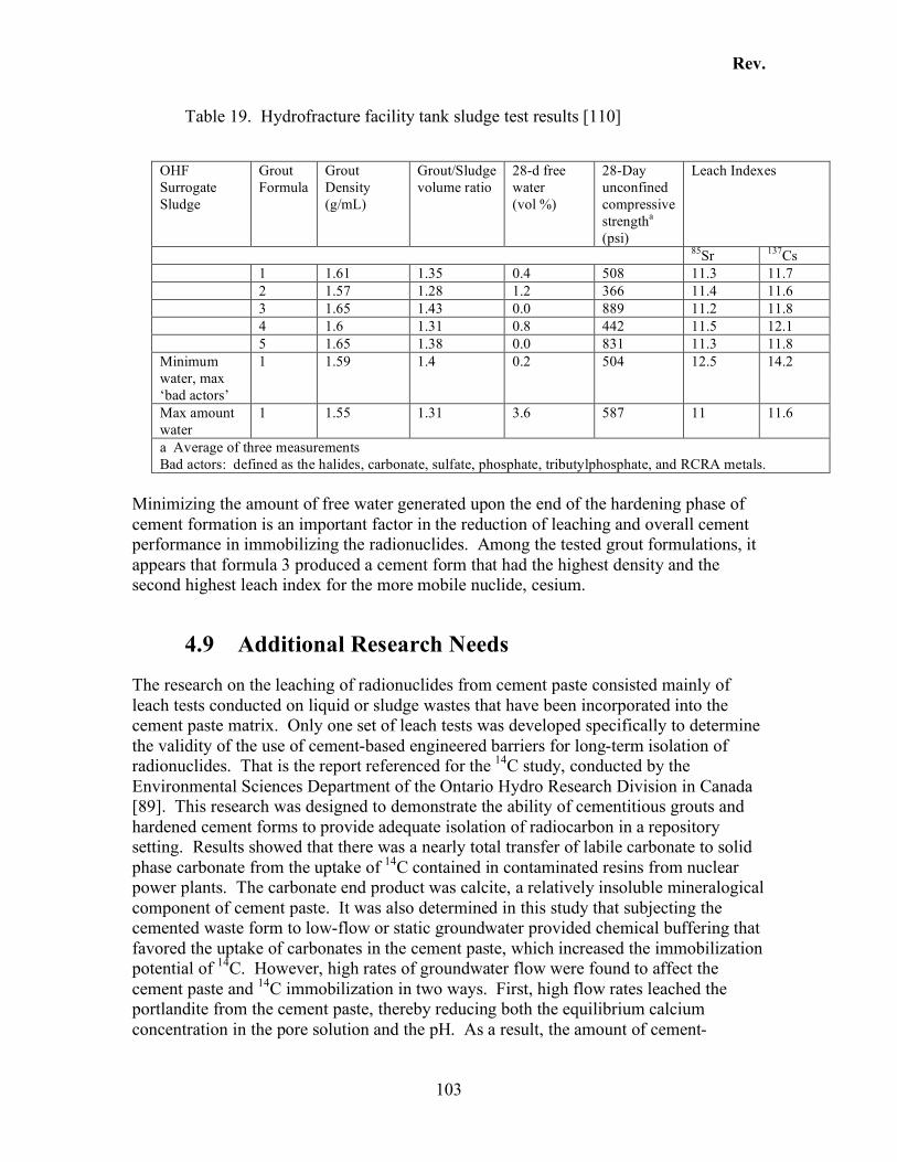
Rev.
103
Table 19. Hydrofracture facility tank sludge test results [110]
OHF Surrogate Sludge
Grout Formula
Grout Density (g/mL)
Grout/Sludge volume ratio
28-d free water (vol %)
28-Day unconfined compressive strengtha (psi)
Leach Indexes
85Sr 137Cs 1 1.61 1.35 0.4 508 11.3 11.7 2 1.57 1.28 1.2 366 11.4 11.6 3 1.65 1.43 0.0 889 11.2 11.8 4 1.6 1.31 0.8 442 11.5 12.1 5 1.65 1.38 0.0 831 11.3 11.8 Minimum water, max ‘bad actors’
1 1.59 1.4 0.2 504 12.5 14.2
Max amount water
1 1.55 1.31 3.6 587 11 11.6
a Average of three measurements Bad actors: defined as the halides, carbonate, sulfate, phosphate, tributylphosphate, and RCRA metals.
Minimizing the amount of free water generated upon the end of the hardening phase of cement formation is an important factor in the reduction of leaching and overall cement performance in immobilizing the radionuclides. Among the tested grout formulations, it appears that formula 3 produced a cement form that had the highest density and the second highest leach index for the more mobile nuclide, cesium.
4.9 Additional Research Needs
The research on the leaching of radionuclides from cement paste consisted mainly of leach tests conducted on liquid or sludge wastes that have been incorporated into the cement paste matrix. Only one set of leach tests was developed specifically to determine the validity of the use of cement-based engineered barriers for long-term isolation of radionuclides. That is the report referenced for the 14C study, conducted by the Environmental Sciences Department of the Ontario Hydro Research Division in Canada [89]. This research was designed to demonstrate the ability of cementitious grouts and hardened cement forms to provide adequate isolation of radiocarbon in a repository setting. Results showed that there was a nearly total transfer of labile carbonate to solid phase carbonate from the uptake of 14C contained in contaminated resins from nuclear power plants. The carbonate end product was calcite, a relatively insoluble mineralogical component of cement paste. It was also determined in this study that subjecting the cemented waste form to low-flow or static groundwater provided chemical buffering that favored the uptake of carbonates in the cement paste, which increased the immobilization potential of 14C. However, high rates of groundwater flow were found to affect the cement paste and 14C immobilization in two ways. First, high flow rates leached the portlandite from the cement paste, thereby reducing both the equilibrium calcium concentration in the pore solution and the pH. As a result, the amount of cement-
Rev.
104
stabilizing carbonate minerals and 14C fixation is lowered. Secondly, leaching lead to a higher porosity pore structure that has large transport coefficients. Both processes, lower calcium concentration and leaching, lead to an increased release rate of 14C. Because entombing a nuclear reactor would involve encapsulating the inside of an above-ground structure, groundwater or other water-source flows would be expected to be low. Therefore, cement paste integrity, and thus high pH conditions, would be expected to prevail, which would result in an expected service lifetime of cementitious barriers to be greater than 105 years. With these repository conditions, 14C would remain immobilized for the entire time it would take for this radionuclide to decay to non-hazardous levels [89]. The implications from all of the leaching tests are that some radionuclide leaching rates, primarily those not complexed in carbonate or hydroxide reactions (e.g., 137Cs), are primarily controlled by diffusion rates through cement paste while others, such as 14C, are observed to maintain a linear, cumulative release with time as controlled by the dissolution of calcite. With portlandite exerting solubility control and a high pH, calcite dissolution rates under low or static-flow leachant rates will remain low (see Section 4.3.3 for a complete listing and explanation of these reactions). In general, experimental data need to be obtained for each nuclide in the radionuclide inventory. The conditions under which leach tests need to be performed must be modified from what have been used. These experimental conditions include those employed in the 14C study entitled “Cement-Based Engineered Barriers For 14C Isolation”[89] and are listed as follows:
• Subject only one side of the cement specimen populated with radionuclide, or radionuclide-contaminated media encapsulated with cement to the leachate to simulate entombment repository conditions. Consider repeating with cementitious slab in upright position with leachate solution being poured down on top of, or percolated up through, the cementitious sample or cemented radionuclide-contaminated media.
• Conduct leach tests using static, low, and high-flow leachate rates.
• Alter the formulation or combine additives and repeat tests to determine optimum
mixture for radionuclide immobilization.
• For those radionuclides that have inorganic forms that are not radioactive, conduct leach tests on cement paste populated with the dissolved inorganic elemental form to determine what the release mechanisms are and to determine, with subsequent tests using the radioactive species of that element, how the radioactivity/radioactive element properties may affect transport and mobilization.
• Alter the environmental conditions of a leach test to approximate conditions of a
given repository, such as temperature, chemical environment, leach solution (match envisioned chemical composition of surface or groundwaters), or other important conditions as discussed in Section 4.3 and Section 4.5.3.
Rev.
105
• Determine the effects that carbonation, via exposure to carbon dioxide or carbonates in solution, has on the leaching potential of the radionuclides of interest. Since carbonation is known to reduce the permeability of cementitious materials, an effort should be made to determine how the permeability reduction, as opposed to calcite complexing of radionuclides affects leach rates and what concentrations of CO2 and environmental conditions (e.g., relative humidity) are ideal to facilitate these radionuclide-retarding reactions.
The information provided here addresses the main issues that would need to be investigated by such research and provides a basis for performance assessments that would need to be conducted in support of entombment of radiologically-contaminated nuclear reactor facilities.
Rev.
106
5 Research Needs The research needs for cementitious fills is common to other applications of cementitious materials to nuclear waste containment: long-term performance. Most of the quantitative research done in this field has been limited to degradation reactions that occur on human time scales (HTS): corrosion of reinforcement, sulfate attack, etc. Research on issues relevant to very long time scales (VLTS) has been limited to approximations of the portlandite and C-S-H stability based on assumptions of solubility coefficients and leach rates. Degradation occurring on HTS can be avoided by using proper material selection and placement. Degradation mechanisms relevant to VLTS depend upon the thermodynamically stable crystalline phases of a cement paste.
5.1 Leaching Data
Although the dissolution constants of the more soluble minerals are known with relatively high confidence, the dissolution constants for C-S-H are more challenging. C-S-H represents the hydrated state of a number of starting minerals such as tricalcium and dicalcium silicate. Moreover, the solubility product of a single hydrated phase is a function of pH, and is (likely) a function of the local calcium:silica molar ratio, which may have been changing during hydration. On a more practical level, the dissolution data for all the relevant mineral phases have not been consolidated to a single location for pubic access. The dissolution constants of all the soluble minerals need to be cataloged so that universal agreement can be reached. The data can be incorporated into a thermodynamic toolkit that could be used to both quantify the VLTS stability of cementitious systems and provide information about the chemical composition of the pore solution.
5.2 Aging Scenarios/Long Term Stability
Degradation that can occur over VLTS (greater than 5000 years) poses a different problem because C-S-H is thermodynamically unstable on these time scales. Over many millennia, the amorphous C-S-H will eventually convert to a number of crystalline calcium silicate phases such as tobermorite, jennite, xonotlite, etc. [90]. These crystalline phases are relatively well understood, and can be synthesized in the laboratory. Fortunately, a precise knowledge of the kinetics of the transformation from amorphous C-S-H to crystalline phases may not be necessary. The half-life of the majority of relevant radionuclides fall into two main groups: less than 50 years and greater than 1000 years. Assuming that a time span of 10 half-lives renders a radionuclide innocuous, the relevant time scales are 500 years and 10 000 years, respectively. For a radionuclide inventory of the shorter half-life group, one can assume C-S-H as the relevant binding
Rev.
107
phase. For a radionuclide inventory of the longer half-life group, one can assume amorphous C-S-H over shorter time scales and assume crystalline calcium silicates are the relevant binding phase over the longer time scales. Degradation of the amorphous C-S-H has been studied at length. The remaining task is to fully characterize the physical and chemical performance of the crystalline phases. Another remaining task is to predict the eventual distribution of crystalline phases for a particular C-S-H paste. Presumably, this will depend on the calcium silica ratio of the amorphous phases. Moreover, it could also depend on the expected temperature history. Fortunately, the oil well cementing industry has a lot of experience in high temperature cementing, which results in stable crystalline calcium silicate phase, and will likely be a good source of information.
5.3 Oxidation State
The mobility of dissolved species in cement paste pore solution can be dominated by the oxidation state of the solution, characterized by an oxidation (or redox) potential Eh. The redox potential determines the oxide distribution [UO2
2+/UO2OH+/U(OH)4o/UO2(OH)3
-] and the valence distribution [U(IV)/U(VI), Fe(II)/Fe(III)] of the atomic species [116]. Predicting the redox potential in ground waters has been an area of study for some time [117, 118], and most of the relevant reaction thermodynamics are known. The difficulty in accurately predicting the redox potential of a pore solution is uncertainty in the redox reaction kinetics [119]. Thermodynamic data yield equilibrium distributions of species. In practice, measurements of Eh fall over a range of values between the limits of water stability [Figure 11.4 in Ref. 116]. Although the discrepancy can be explained, in part, by the presence of peroxide (H2O2) [120], the combination of experimental difficulties and the effects of kinetics have lead to the development of a disequilibrium approach [121] that relies upon additional experimental data to constrain the speciation calculation.
5.4 Surface Complexation Modeling
One of the most important aspects of predicting long term performance of concrete is accurately predicting transport. Transport of ionic species through concrete can be dominated by binding; interaction between the diffusing species and the solid pore wall. Historically, the amount of species adsorbed by a porous solid has been characterized by a partitioning coefficient Kd. Alternatively, people have used empirical adsorption-desorption isotherms. In both cases, the approach describes exactly the response of a cement paste to the exposure solution. Furthermore, one can expose a cement paste to different concentrations and then develop a concentration dependent binding coefficient. Within the parameter space over which the binding coefficient was determined, one can interpolate to estimate binding. Outside the parameter space, however, these empirical approaches offer no reliable assurance of how the material will respond. For geological systems, the environmental exposure will change over geological time scales. For
Rev.
108
concretes near the water table, exposure conditions can change dramatically over human time scales. Surface complexation modeling is a means of quantifying surface interactions, based on the chemical state of the system and the surface charge on the pore walls [122, 123]. By enumerating the surface complexation reactions, along with the equilibrium coefficients, one has a basis for extrapolating performance. Although this approach requires more effort than the partitioning coefficient, it would eventually reduce the amount of testing required on future concretes because the hydrated phases among cements is relatively constant; the important parameter is the relative fractions of each phase. Although many surface reactions have been characterized for geochemical applications, there is still a need to extend this database to cement-based materials. A large component of the remaining work is to characterize the surface properties of C-S-H so that one can reliably characterize the chemical makeup of the double layer near the pore wall surface.
Rev.
109
6 References
1. “Standard Specification for Portland Cement,” ASTM C 150, ASTM International.
2. U.S. Code of Federal Regulations, “Standards for Protection Against Radiation,” 10CFR20, National Archives and Records Administration, (http://www.gpoaccess.gov/cfr/index.html). 3. U.S. Code of Federal Regulations, “Radiological Criteria for License Termination,” 10CFR20 Subpart E, National Archives and Records Administration, (http://www.gpoaccess.gov/cfr/index.html).
4. U.S. Code of Federal Regulations, “Reporting and Recordkeeping for Decommissioning Planning,” 10CFR50.75, National Archives and Records Administration, (http://www.gpoaccess.gov/cfr/index.html). 5. U.S. Code of Federal Regulations, “Termination of License,” 10CFR50.82, National Archives and Records Administration, (http://www.gpoaccess.gov/cfr/index.html). 6. U.S. Code of Federal Regulations, “Postconstruction Environmental Reports,” 10CFR51.53, National Archives and Records Administration, (http://www.gpoaccess.gov/cfr/index.html).
7. U.S. Code of Federal Regulations, “Postconstruction Environmental Impact Statements,” 10CFR51.95, National Archives and Records Administration, (http://www.gpoaccess.gov/cfr/index.html). 8. W.D. Travers, “Information Paper on the Viability of Entombment as a Decommissioning Option for Power Reactors”, SECY-99-187, U.S. Nuclear Regulatory Commission, July 1999.
9. U.S. Code of Federal Regulations, “Licensing Requirements for Land Disposal of Radioactive Waste,” 10CFR61, National Archives and Records Administration, (http://www.gpoaccess.gov/cfr/index.html). 10. NRC Performance Assessment Working Group, “A Performance Assessment Methodology for Low-Level Radioactive Waste Disposal”, NUREG-1573, U.S. Nuclear Regulatory Commission, October 2000.
11. U.S. Code of Federal Regulations, “Disposal Site Suitability Requirements for Land Disposal,” 10CFR61.50, National Archives and Records Administration. (http://www.gpoaccess.gov/cfr/index.html). 12. R.I. Smith, “Entombment Experience in the U.S,” SECY-99-187 (Appendix A), U.S. Nuclear Regulatory Commission, 1999.
Rev.
110
13. C.A. Langton, R.D. Spence, and J. Barton, “State of the Art Report on High-Level Waste Tank Closure” WSRC-TR-2001-00359, Westinghouse Savannah River Company, Aiken, SC, 2001.
14.T.B. Caldwell, P.D. d’Entremont, C.A. Langton, J.L. Newman, E. Saldivar, and N. Rajendran, 1998, and “Closing High-Level-Waste Tanks at the Savannah River Site,” RADWASTE Magazine, 19-26, March 1998. 15. T.H. Lorier, D.H. Miller, W.L. Mhyre, J.R. Harbour, and C.A. Langton, “Grout Formulations for Closing Hanford High-Level Waste Tanks: Bench Scale Study,” WSRC-TR-2003-00447, Rev.0, Westinghouse Savannah River Company, Aiken, SC, 2003. 16. C.A. Langton, J.R. Harbour, D.H. Miller, C.N. Shramek, J. Carroll, E. Johnson, and A.L. Furgeson, “Grout Placement and Property Evaluation for Closing Hanford High-Level Waste Tanks: Scale Up Report,” WSRC-TR-2003-00556, Rev.0, Westinghouse Savannah River Company, Aiken, SC, 2003. 17. C.A. Langton, “Fill Materials for R-Basin Closure,” WSRC-TR-2001-00048, Rev.0, Westinghouse Savannah River Company, Aiken, SC, 2001. 18. G.G. Loomis et al., “Final Results Report, In Situ Grouting Technology for Application in Buried Transuranic Waste Sites, Volume 1, Technology Description and Treatability Study Results for Operable Unit 7-13/14”, INEEL/EXT-02-00233, Rev. 1, Idaho National Engineering and Environmental Laboratory, August 2002. 19. “Measurement of the Leachability of Solidified Low-Level Radioactive Wastes by a Short-Term Test Procedure,” ANSI 16.1, American National Standards Institute. 20. K.A. Snyder, “Condition Assessment of Concrete Nuclear Structures Considered for Entombment,” NISTIR 7026, National Institute of Standards and Technology, Gaithersburg, MD, 2004.
21. A.M. Neville, Properties of Concrete, 4th Edition, John Wiley & Sons, Inc., 1998. 22. M.H. Bradbury and F.-A. Sarott, “Sorption Databases for the Cementitious Near-Field of a L/ILW Repository for Performance Assessment,” PSI Bericnt Nr. 95-06, ISSN 1019-0643. Paul Scherrer Institut, Villigen, Switzerland, 1995.
23. I.G. McKinley and A. Scholtis, “A Comparison of Radionuclide Sorption Databases Used in Recent Performance Assessments,” J. Contam. Hydrol. 13, 347-363, 1993.
24. ACI Manual of Concrete Practice American Concrete Institute, Farmington Hills, MI (Published Annually).
25. ACI Committee 318, “Building Code Requirements for Structural Concrete (ACI 318-02) and Commentary (ACI 318R-02)”, (ACI 318-02) in ACI Manual of Concrete Practice, Part 3, American Concrete Institute, 2002. 26. ACI Committee 201, “Guide to Durable Concrete,” (ACI 201.2R-01) in ACI Manual of Concrete Practice, Part 1, American Concrete Institute, 2001.
Rev.
111
27. ASTM International, Annual Book of ASTM Standards, (Section 4 – Construction: Volume 04.01, Volume 04.05), ASTM International, West Conshohocken, PA (Published Annually).
28. C. Hendrickson and T. Au, Project Management for Construction, Prentice Hall, 1989.
29. ACI Committee 116, “Cement and Concrete Terminology,” (ACI 116R-00) in ACI Manual of Concrete Practice, Part 1, American Concrete Institute, 2003.
30. A.M. Haimoni, “Grouting – Materials and Techniques on the Approach to the Millennium,” in Specialist Techniques and Materials for Concrete Construction, Editors: R.K. Dhir and N.A. Anderson, Proc. of the Int. Conf. Univ. of Dundee, UK, September 1999.
31. J. Warner, Practical Handbook of Grouting: Soil, Rock and Structures, John Wiley, New Jersey, 2004.
32. V.A. Hackley and C.F. Ferraris, "The Use of Nomenclature in Dispersion Science and Technology," NIST Recommended Practice Guide, SP 960-3, National Institute of Standards and Technology, 2001. 33. S. Amziane and C. F. Ferraris “Monitoring of Setting Evolution of Cementitious Materials by Measurements of Rheological Properties and Pore Water Pressure”, to be submitted to ACI Mater. J., 2006.
34. A. Naudts, E. Landry, S. Hooey, and W. Naudts, “Additives and Admixtures in Cement Based Grouts”, in Grouting and Ground Treatment, Proc. of the 3rd Int. Conf., Editors: L. F. Johnsen, M.J. Byle, D. A. Bruce, 1188-1191, 2003. 35. R.C. Dolence and E.Giovannitti, “Utilization of Coal Ash/Coal Combustion Products for Mine Reclamation” in Proc. of American Power Conference, 59-2, 837-840, 1997. 36. D.E. Stump, “Grouting to Control Mine Aubsidence” ASCE Geothechnical Special Publication No. 80, 128-138, American Society of Civil Engineers, 1998. 37. P.R. Healy and J.M. Head, Construction Over Abandoned Mine Workings, CIRIA, London, 1984. 38. D.E. Sherwood and M. Gandais, “Neutral Mineral Micro Particle Grout and its Application in Recovery of a Collapsed Tunnel in Switzerland”, in Grouting in the Ground: Proc. of the Conf. Organized by the Inst. of Civ. Eng., London, 631-648, 1992.
39. D. Johnson, “Cementitious Grouts – Standards Update 1999” in Specialist Techniques and Materials for Concrete Construction, Editors: R.K. Dhir and N.A. Anderson, Proc. of the Int. Conf. Univ. of Dundee, UK, September 1999. 40. M.C. Santagata and E. Santagata, “Experimental Investigation of Factors Affecting Injectability of Micro-cement Grouts,” in Grouting and Ground Treatment, Proc. of the 3rd Int. Conf., Editors: L. F. Johnsen, M.J. Byle, D. A. Bruce, 1121-1234, 2003.
Rev.
112
41. M. Chuaqui, D. A. Bruce, “Mix Design and Quality Control Procedures for High Quality Mobility Cement Based Grouts”, in Grouting and Ground Treatment, Proc. of the 3rd Int. Conf., Editors: L. F. Johnsen, M.J. Byle, D. A. Bruce, 1153-1168, 2003
42. C.F. Ferraris, “Measurement of the Rheological Properties of High Performance Concrete: State of the Art Report” J. Res. NIST 104 (5), 461-478, 1999.
43. E. Koehler, “Development of a Portable Rheometer for Fresh Portland Cement Concrete”, Thesis, Univ. of Texas at Austin, 2004.
44. C. Ferraris, L. Brower (Editors), “Comparison of Concrete Rheometers: International Tests at LCPC (Nantes, France) in October 2000,” NISTIR 6819, National Institute of Standards and Technology, September 2001. 45. L. Brower, C.F Ferraris, “Comparison of Concrete Rheometers”, Concrete International 25 (8), 41-47, August 2003. 46. C. Ferraris, L. Brower (Editors), “Comparison of Concrete Rheometers: International Tests at MB (Cleveland OH, USA) in May 2003,” NISTIR 7154, National Institute of Standards and Technology, September 2003.
47. C.F. Ferraris, N.S. Martys, “Relating Fresh Concrete Viscosity Measurements from Different Rheometers”, J. Res. NIST. 108, 2003.
48. “Standard Test Method for Flow of Grout for Preplaced-Aggregate Concrete (Flow Cone Method),” ASTM C 939-97, ASTM International.
49. “Standard Specification for Flow Table for Use in Tests of Hydraulic Cement”, ASTM C 230-98, ASTM International.
50. “Test Method for Chemical Shrinkage of Hydraulic Cement Pastes”, ASTM C 1608, ASTM International.
51. L.J. Parrott, M. Geiker, W.A. Gutteridge, and D. Killoh, “Monitoring Portland Cement Hydration: Comparison of Methods,” Cem. Concr. Res. 20, 919-926, 1990.
52. “Standard Test Method for Drying Shrinkage of Mortar Containing Hydraulic Cement”, ASTM C 596-96, ASTM International.
53. M. Sherman, P. Kelley, J. Bae, “ Controlling Concrete Cracking and Curling”, Concrete International 26, 59-62, 2004.
54. “Standard Specification for Expansive Hydraulic Cement”, ASTM C 845-96, ASTM International.
55. ACI 237 state of the art report, in review. 56. “Standard Test Method for Bleeding of Concrete”, ASTM C 232-99, ASTM International.
Rev.
113
57. “Standard Test Method for Expansion and Bleeding of Freshly Mixed Grouts for Preplaced-Aggregate Concrete in the Laboratory”, ASTM C 940-98a, ASTM International.
58. “Standard Test Method for Time of Setting of Hydraulic Cement Mortar by modified Vicat Needle”, ASTM C807-99, ASTM International.
59. “Standard Test Method for Time of Setting of Hydraulic Cement by Vicat Needle”, ASTM C 191-99, ASTM International.
60. S. Amziane, “Setting Time Determination of Cementitious Material Based on Measurements of the Pore Water Pressure Variations,” Cem. Concr. Res. 36 (2), 295-304, 2006. 61. P.D. Tennis, S.K. Kosmatka, “Cement Characteristics” Chapt. 9.1 from “Innovations in Portland Cement Manufacturing”, Ed. J.I. Bhatty, F.M. Miller, S.H. Kosmatka, PCA – CD-ROM, 1091-1093, 2004.
62. “Standard Test Method for Heat of Hydration of Hydraulic Cement,” ASTM C186-98, ASTM International.
63. D.D. Gray, T.P. Reddy, D.C. Black, P.F. Ziemkiewicz, “Filling Abandoned Mines with Fluidized Bed Combustion Ash Grout”, in The design and Application of Controlled Low-Strength Materials (Flowable fill), Editors: K. Howard, J.L. Hitch, ASTM STP 1331, ASTM International, 1998.
64. S.T. Jarvis, T.G. Brooks, “The Use of PFA- Cement Pastes in the Stabilization of Abandoned Mine Workings”, Waste Manage. 16, 135-143, 1996.
65. R. M. Berry, L. Narduzzo, “Radioactive Waste Trench Grouting: a Case History at Oak Ridge National Laboratory”, in Grouting-Compaction, Remediation and Testing, Proc. Sessions at Logan UT, Editor Vipulanandan, 1997. 66. G. J. Hawkins, J.I. Bhatty, A. T. O’Hare, “Cement Kiln Dust Generation and Management,” in Innovations in Portland Cement Manufacturing, J.I. Bhatty, F.M. Miller, and S.H. Kosmatka (Eds.), Portland Cement Association, Skokie, IL, 735-779, 2004. 67. J.W. Bullard, C.F. Ferraris, E.J. Garboczi, N. Martys, and P. Stutzman, “ Virtual Cement,” in Innovations in Portland Cement Manufacturing, J.I. Bhatty, F.M. Miller, and S.H. Kosmatka (Eds.), Portland Cement Association, Skokie, IL, 1311-1331, 2004. 68. U.S. Code of Federal Regulations, “Criteria for License Termination Under Restricted Conditions,” 10CFR20.1403, National Archives and Records Administration, (http://www.gpoaccess.gov/cfr/index.html).
69. S.M. Short, “Isolation Assessment,” SECY-99-187 (Appendix B), U.S. Nuclear Regulatory Commission Report by Pacific Northwest National Laboratory, Richland, WA. July, 1999.
Rev.
114
70. R.I. Smith, S.M. Short. “Viability of the Entombment Option as an Alternative for Decommissioning” SECY-99-187 Attachment 2, U.S. Nuclear Regulatory Commission Report by Pacific Northwest National Laboratory, Richland, WA. May, 1999.
71. U.S. Code of Federal Regulations, “Waste Classification,” 10CFR61.55, National Archives and Records Administration, (http://www.gpoaccess.gov/cfr/index.html).
72. F.P. Glasser, “Progress in the Immobilization of Radioactive Wastes in Cement,” Cem. Concr. Res. 22, 201-216, 1992.
73. S. Miller, “Review of Cement Chemistry and Stability For Low-Level Radioactive Waste Disposal Environments,” August, 1998.
74. M.J. McCulloch, M.J. Angus, R.W. Crawford, A.A. Rahman, and F.P. Glasser, “Cements in Radioactive Waste Disposal: Some Mineralogical Considerations,” Mineral. Mag. 49, 211-221, 1985. 75. M. Atkins and F.P. Glasser, “Application of Portland Cement-Based Materials to Radioactive Waste Immobilization,” Waste Manage. 12, 105-131, 1992. 76. S.H. Kosmatka, W.C. Panarese, “Design and Control of Concrete Mixtures,” in Thirteenth Edition of Portland Cement Association, Skokie, Illinois, 1992. 77. M. Atkins and F.P. Glasser, “Modeling the Geochemical Degradation of Cements in a Waste Repository,” Mineral. Mag. 58A, 29-39, 1994. 78. U.R. Berner, “Evolution of Pore Water Chemistry During Degradation of Cement in a Radioactive Waste Repository Environment,” Waste Manage.t 12, 201-219, 1992. 79. C.J. Bruton, B.L. Phillips, A. Meike, S. Martin, B.E. Viani, “Cement Minerals at Elevated Temperature: Thermodynamic and Structural Characteristics,” in Scientific Basis for Nuclear Waste Management XVII, A. Barkatt and R.A. Van Konynenburg, Eds., Mat. Res. Soc. Symp. Proc. 333, Materials Research Society, Pittsburgh, Pennsylvania, 327-334, 1994.
80. W. Jiang, D.M. Roy, “Ancient Analogues Concerning Stability and Durability of Cementitious Wasteform,” in Scientific Basis for Nuclear Waste Management XVII, A. Barkatt and R.A. Van Konynenburg, Eds., Mat. Res. Soc. Symp. Proc. 333, Materials Research Society, Pittsburgh, Pennsylvania, 335-340, 1994. 81. J.H. Thomassin and F. Rassineus, “Ancient Analogues of Cement-Based Materials: Stability of Silicate Hydrates,” Appl. Geochem. 7 (2), 137-142, 1992.
82. C.A. Rochelle, K. Baseman, A.E. Milodowski, D.J. Noy, J. Pearce, and D. Savage, “Reactions of Cement Pore Fluids with Rock: Implications for Migration of Radionuclides,” in Water-Rock Interaction (Kharaka and Maest, Eds.), Balkema, Rotterdam, 423-426, 1992.
83. A. Atkinson, N.M. Everitt, and R.M. Guppy, “Time Dependence of pH in a Cementitious Repository,” Mat. Res. Soc. Symp. Proc. 127, Materials Research Society, Pittsburgh, Pennsylvania, 439-446, 1989.
Rev.
115
84. A. Atkinson, A. Hearne, and C.F. Knight, “Aqueous Chemistry and Thermodynamic Modeling of CaO-SiO2-H2O Gels,” J. Chem. Soc. Dalton 7, 2371-2379, 1989. 85. U. Berner, “A Thermodynamic Description of the Evolution of Pore Water Chemistry and Uranium Speciation During the Degradation of Cement,” Technical Report 90-12, Paul Scherrer Inst., Baden, Switzerland, 1990.
86. A. Haworth, S.M. Sharland, and C. J. Tweed, “Modeling of the Degradation of Cement in a Nuclear Waste Repository,” Mat. Res. Soc. Symp. Proc. 127, Materials Research Society, Pittsburgh, Pennsylvania, 447-454, 1989. 87. U.S. Code of Federal Regulations, “Waste Characteristics,” 10 CFR 61.56, National Archives and Records Administration, (http://www.gpoaccess.gov/cfr/index.html). 88. W. Stumm and J.J. Morgan, Aquatic Chemistry, Chemical Equilibria and Rates in Natural Waters, Third Edition, Wiley-Interscience, John Wiley & Sons, New York, 1996. 89. R. Dayal and E.J. Reardon, “Cement-Based Engineered Barriers For Carbon-14 Isolation,” Waste Manage. 12, 189-200, 1992. 90. H.F.W. Taylor, Cement Chemistry, Academic Press, New York, 1990.
91. J.M. Pommersheim and J.R. Clifton, “Expansion of Cementitious Materials Exposed to Sulfate Solutions,” in Scientific Basis for Nuclear Waste Management XVII, A. Barkatt and R.A. Van Konynenburg, Eds., Mat. Res. Soc. Symp. Proc., 333, Materials Research Society, Pittsburgh, Pennsylvania, 363-368, 1994.
92. F.H. Huang, D.E. Mitchell, J.M. Conner, “Low-Level Radioactive Wastes Immobilized by Cement-Based Grouts,” Radioactive Waste Management 107, 254-266, 1994. 93. J. Philip and J.R. Clifton “Concrete as an Engineered Alternative to Shallow Land Disposal of Low Level Nuclear Waste: Overview,” in Fly Ash, Silica Fume, Slag and Natural Pozzolans in Concrete, V.M. Malhotra, Ed., Proc 4th Int’l. Conf. Instanbul, Turkey, American Concrete Inst., Detroit, Michigan, 713-731, 1993. 94. Rogers, R. D., M. A. Hamilton, R. H. Veeh, and J. W. McConnell, “Development of Methodology to Evaluate Microbially Influenced Degradation of Cement-Solidified Low-Level Radioactive Waste Forms,” in Scientific Basis for Nuclear Waste Management XVII, A.Barkatt and R. A. Van Konynenburg, Eds., Mat. Res. Soc. Symp. Proc. 333, Materials Research Society, Pittsburgh, Pennsylvania, pp. 349-356, 1994
95. J. Corbo and H. Farazam, “Influence of Three Commonly Used Inorganic Compounds on Pore Solution Chemistry and Their Possible Implications to the Corrosion of Steel in Concrete,” ACI Mater. J. 86 (5), 498-502, 1989. 96. J.C. Worthington, D.G. Bonner, and D.V. Nowell, “Influence of Cement Chemistry on Chloride Attack of Concrete,” Mater. Sci. and Technol. 4, 305-313, 1988.
Rev.
116
97. “Standard Test Method for Determination of the Proportion of Phases in Portland Cement and Portland-Cement Clinker Using X-Ray Powder Diffraction Analysis,” ASTM C 1365-98, ASTM International.
98. T. Banba, J. Matsumoto, S. Mukaoka, “Leaching Behavior of Carbon-14 Contained in Portland Cement,” Cem. Concr. Res. 22, 381-386, 1992.
99. T.C. Powers, L.E. Copeland, and H.M. Mann, “Capillary continuity or discontinuity in cement paste,” PCA Bulletin, 10, 2-12, 1959.
100. S. Caijun, R. Spence, “Designing of Cement-Based Formula for Solidification/Stabilization of Hazardous, Radioactive, and Mixed Wastes,” Critical Reviews in Environmental Science and Technology, 34, 391-417, 2004. 101. United States Nuclear Regulatory Commission, Office of Nuclear Material Safety and Safeguards, Washington D.C., Technical Position on Waste Forms, Rev. 1, 1991. 102. H. Matsuzuru, N. Moriyama, “Leaching of Radionuclides from a Cement Composite Incorporating Evaporator Concentrates Generated at a Pressurized Water Reactor Nuclear Power Plant,” Nucl. Sci. Engin. 80, 14-25, 1982.
103. P. Barret, J.M. Casabonne-Masonnave, and D. Damidot, “Short Term Processes of Radionuclide Immobilization in Cement: A Chemical Approach,” Appl. Geochem 7, 109-124, 1992. 104. R.J. Silva, and H. Nitsche, “Actinide Environmental Chemistry,” Radiochimica Acta, 70/71, 377-396, 1995. 105. United States Department of Energy, “Vadose Zone Characterization Project at the Hanford Tank Farms, SX Tank Farm Report” DOE/ID/12584-268, GJPO-HAN-4, prepared by MACTEC-ERS for the U.S. DOE Grand Junction Office, Grand Junction, CO, 1996. 106. T. Nishi, M. Matsuda, K. Chino, M. Kikuchi, “Reduction of Cesium Leachability From Cementitious Resin Forms Using Natural Acid Clay and Zeolite,” Cem. Concr. Res. 22, 387-392, 1992.
107. T.M. Krishnamoorthy, S. Joshi, G.R. Doshi, R.N. Nair, “Desorption Kinetics of Radionuclides Fixed in Cement Matrix,” Nucl. Technol. 104, 351-357, 1993.
108. J.M. Lee, K. Jooho, L. Chang, J.W. Park, “Leachability of Radionuclides From Cement Solidified Waste Form Produced at Korean Nuclear Power Plant,” J. Environ. Sci. Heal. A 37 (2), 201-212, 2002. 109. A.M. El-Kamash, A.M. El-Dakroury, H.F. Aly, “Leaching Kinetics of 137Cs and 60Co Radionuclides fixed in cement and cement-based materials,” Cem. Concr. Res. 32, 1797-1803, 2002.
110. R.D. Spence, C.H. Mattus, “Laboratory Stabilization/Solidification of Tank Sludges: GAAT, OHF, and combined tank sets,” J. Environ. Manage. 70, 203-214, 2004.
Rev.
117
111. C.V. McIsaac, “Leachability of Chelated Ion-Exchange Resins Solidified in Dement or Cement and Fly Ash,” Waste Manage. 13, 41-54, 1993. 112. D.C. Grant, E.E. Smeltzer, M.C. Skriba, J.C. Cwynar, L.R. Elsenstatt, “Leachability of cement encapsulated West Valley RadWaste Streams, Westinghouse R&D Center, Pittsburgh, Pennsylvania,” Mat. Res. Soc. Symp. Proc. 44, 875-882, 1985.
113. S. Komarneni, D.M. Roy, “Mechanisms of Immobilization of Nuclear Waste Elements by Cement Minerals, Cement and Morter,” Cem. Concr. Res. 11, 789-794, 1981. 114. K. Sakr, M.S. Sayed, N. Hafez, “Comparison Studies between cement and cement-kaolinite properties for incorporation of low-level radioactive wastes,” Cem. Concr. Res. 27, 1919-1926, 1997.
115. A. Osmanlioglu, “Immobilization of Radioactive Waste by Cementation with purified Kaolin Clay,” Waste Manage. 22, 481-483, 2002.
116. D. Langmuir, Aqueous Environmental Geochemistry, Prentice Hall, 1997. 117. W. Stumm and J.J. Morgan, Aquatic Chemistry: An Introduction Emphasizing Chemical Equilibria in Natural Waters, Wiley-Interscience, New York, 1970. 118. F.M.M. Morel, Principles of Aquatic Chemistry, Wiley-Interscience, New York, 1983. 119. C.M. Bethke, Geochemical Reaction Modeling, Oxford University Press, New York, 1996. 120. M. Sato and H.M. Mooney, Geophys. 25, 226-249, 1960.
121. D.K. Nordstrom, R.H. McNutt, I. Puigdomenech, J.A.T. Smellie, and M. Wolf, J. Geochem. Explor. 45, 249-287, 1992.
122. D.A. Dzombak and F.M.M. Morel, Surface Complexation Modeling: Hydrous Ferric Oxide, Wiley-Interscience, New York, 1990.
123. M.F. Hochella and A.F. White (Eds.), Mineral-Water Interface Geochemistry, From: Reviews in Mineralogy (Volume 23), Mineralogical Society of America, Washington D.C., 1990.