Embed Size (px)
Citation preview
Use of polymer flexible joint between RC frames and masonry infills for improved seismic performance
Arkadiusz Kwiecień 1, Matija Gams 2, Alberto Viskovic 3, Paweł Kisiel 1, Jože Korelc 4, Theodoros Rousakis 5 1 Cracow University of Technology, Cracow, Poland 2 Slovenian National Building and Civil Engineering (ZAG), Ljubljana, Slovenia 3 University "G. d'Annunzio" of Chieti – Pescara, Chieti, Italy 4 University of Ljubljana, Ljubljana, Slovenia 5 Democritus University of Thrace, Xanthi, Greece
ABSTRACT: In the paper, an innovative solution for the problem of damage occurrence to masonry infills in r.c. frame structures during earthquakes is presented and analyzed using experimental testing and numerical calculations. In an attempt to alleviate the problem of premature damage to infills while retaining the structural interaction between infill and frame, an idea of using flexible polyurethanes (polymer PM) between the r.c. frame and masonry infill was proposed. In the experimental research part, the behavior of the polymer of stiffness E ≈ 4 MPa and ultimate strain of up to 150% is studied with monotonic and cyclic shear tests of the joint on a large-scale specimen. Results obtained from analysis confirmed that despite the flexibility of the polymer, the brick-to-concrete joint would be capable of transferring significant loads during in-plane and out-of-plane excitations. The proposed innovative method can be used as a structural element applied to new buildings, as pre-seismic retrofit of existing ones or during rehabilitation works after earthquakes.
1 INTRODUCTION
1.1 Behavior of masonry infills in r.c. frame structures under lateral loads
Buildings having brick wall infills in r.c. frame structures (Fig. 1) are widely used all around the world as constructions resistant to earthquakes. Unfortunately, present experience after many earthquakes shows that they are vulnerable to large deformations, resulting in serious collapses with many victims during earthquakes. Damage to masonry infills in r.c. frame structures during earthquakes may occur at relatively modest earthquake intensity because the stiff infills are rigidly connected to the flexible frames. The infills may contribute significantly to lateral stiffness as well as resistance of such construction systems depending on their strength and stability (type of brick wall, thickness or even type of concrete slab and beam casting). In general masonry elements are vulnerable to cyclic loads, cracking earlier than concrete frames during seismic excitation under stress concentrations generated by moving frames (Fig 2a) if shear failures in concrete frames are suppressed. Among different types of infill behavior, the desirable sequence of damages is the development of diagonal cracks due to inclined tensile stress, followed by inevitable crushing of masonry infill at corners under compression stress
concentration (Fig. 2b) at very high lateral deformation of the concrete frame. Alternatively, transfer of high diagonal force and shear may destroy undesirably the r.c. columns or concrete joint area (Fig. 2b). Figure 3b shows the most vulnerable rc column – brick wall infill interaction because of the formation of short columns under extremely high shear demands. In other cases the masonry walls lose their initial resistance and integrity, causing the “out of function” condition of the building even if the main frame structure is not damaged (Fig. 3a). Such cracked masonry panels may be very dangerous during aftershocks, because they may not be very well fixed to the framed structure as well as cohesion between defragmented masonry parts may be very low. This fact causes high costs to the citizens, to the Government and to the Society because people are threatened by out-of-plane failure modes (Fig. 4).
1.2 Description of innovative approach
In any of the abovementioned cases, the uncertainty in the behavior of brick wall infills and in their interaction with r.c. frames raises the uncertainty in estimating even with advanced 3D inelastic the collapse mechanism of existing buildings. Similar is the problem even in the collapse mechanism of retrofitted building if strong r.c. walls (or equivalent elements) are not included in redesign strategy.
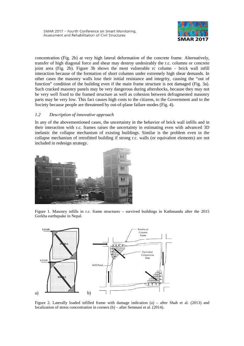
Figure 1. Masonry infills in r.c. frame structures – survived buildings in Kathmandu after the 2015 Gorkha earthquake in Nepal.
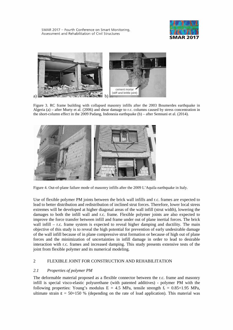
a) b)
Figure 2. Laterally loaded infilled frame with damage indication (a) – after Shah et al. (2013) and localization of stress concentration in corners (b) – after Semnani et al. (2014).
a) b)
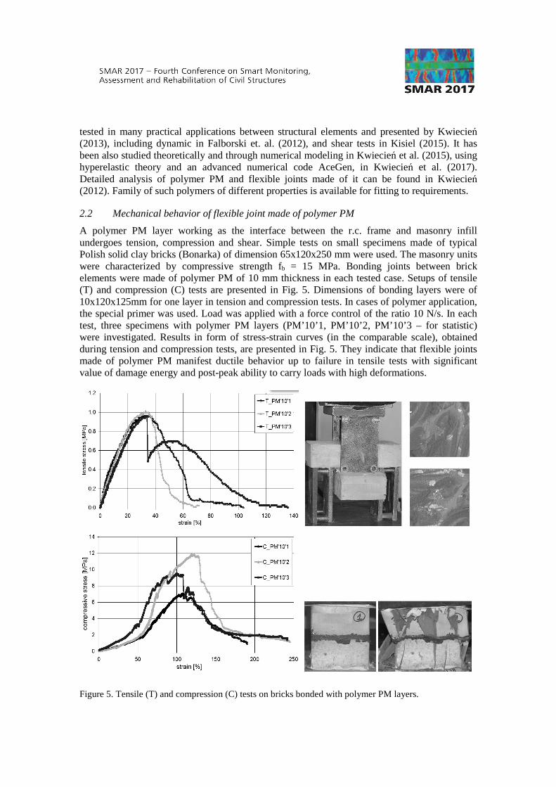
cement mortar(stiff and brittle joint)
Figure 3. RC frame building with collapsed masonry infills after the 2003 Boumerdes earthquake in Algeria (a) – after Murty et al. (2006) and shear damage to r.c. columns caused by stress concentration in the short-column effect in the 2009 Padang, Indonesia earthquake (b) – after Semnani et al. (2014).
Figure 4. Out-of-plane failure mode of masonry infills after the 2009 L’Aquila earthquake in Italy.
Use of flexible polymer PM joints between the brick wall infills and r.c. frames are expected to lead to better distribution and redistribution of inclined strut forces. Therefore, lower local stress extremes will be developed at higher diagonal areas of the wall infill (strut width), lowering the damages to both the infill wall and r.c. frame. Flexible polymer joints are also expected to improve the force transfer between infill and frame under out of plane inertial forces. The brick wall infill – r.c. frame system is expected to reveal higher damping and ductility. The main objective of this study is to reveal the high potential for prevention of early undesirable damage of the wall infill because of in plane compressive strut formation or because of high out of plane forces and the minimization of uncertainties in infill damage in order to lead to desirable interaction with r.c. frames and increased damping. This study presents extensive tests of the joint from flexible polymer and its numerical modeling.
2 FLEXIBLE JOINT FOR CONSTRUCTION AND REHABILITATION
2.1 Properties of polymer PM
The deformable material proposed as a flexible connector between the r.c. frame and masonry infill is special visco-elastic polyurethane (with patented additives) - polymer PM with the following properties: Young’s modulus E = 4.5 MPa, tensile strength ft = 0.85÷1.95 MPa, ultimate strain ε = 50÷150 % (depending on the rate of load application). This material was
tested in many practical applications between structural elements and presented by Kwiecień (2013), including dynamic in Falborski et. al. (2012), and shear tests in Kisiel (2015). It has been also studied theoretically and through numerical modeling in Kwiecień et al. (2015), using hyperelastic theory and an advanced numerical code AceGen, in Kwiecień et al. (2017). Detailed analysis of polymer PM and flexible joints made of it can be found in Kwiecień (2012). Family of such polymers of different properties is available for fitting to requirements.
2.2 Mechanical behavior of flexible joint made of polymer PM
A polymer PM layer working as the interface between the r.c. frame and masonry infill undergoes tension, compression and shear. Simple tests on small specimens made of typical Polish solid clay bricks (Bonarka) of dimension 65x120x250 mm were used. The masonry units were characterized by compressive strength fb = 15 MPa. Bonding joints between brick elements were made of polymer PM of 10 mm thickness in each tested case. Setups of tensile (T) and compression (C) tests are presented in Fig. 5. Dimensions of bonding layers were of 10x120x125mm for one layer in tension and compression tests. In cases of polymer application, the special primer was used. Load was applied with a force control of the ratio 10 N/s. In each test, three specimens with polymer PM layers (PM’10’1, PM’10’2, PM’10’3 – for statistic) were investigated. Results in form of stress-strain curves (in the comparable scale), obtained during tension and compression tests, are presented in Fig. 5. They indicate that flexible joints made of polymer PM manifest ductile behavior up to failure in tensile tests with significant value of damage energy and post-peak ability to carry loads with high deformations.
Figure 5. Tensile (T) and compression (C) tests on bricks bonded with polymer PM layers.
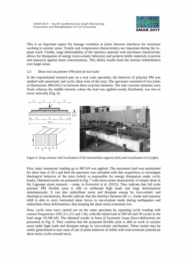
This is an important aspect for damage evolution at joints between interfaces for structures working in seismic areas. Tensile and compression characteristics are important during the in–plane work. Visibly, large deformability of the interface material with non-linear characteristic allows for dissipation of energy (visco-elastic behavior) and protects brittle materials (concrete and masonry) against stress concentrations. This ability results from the stresses redistribution over larger areas.
2.3 Shear test on polymer PM joint of real scale
In the experimental research part on a real scale specimen, the behavior of polymer PM was studied with monotonic and cyclic shear tests of the joint. The specimen consisted of two joints of dimensions 308x20x2 cm between three concrete elements. The side concrete elements were fixed, whereas the middle element, where the load was applied evenly distributed, was free to move vertically (Fig. 6).
Figure 6. Setup scheme with localization of the intermediate supports (left) and visualization of it (right).
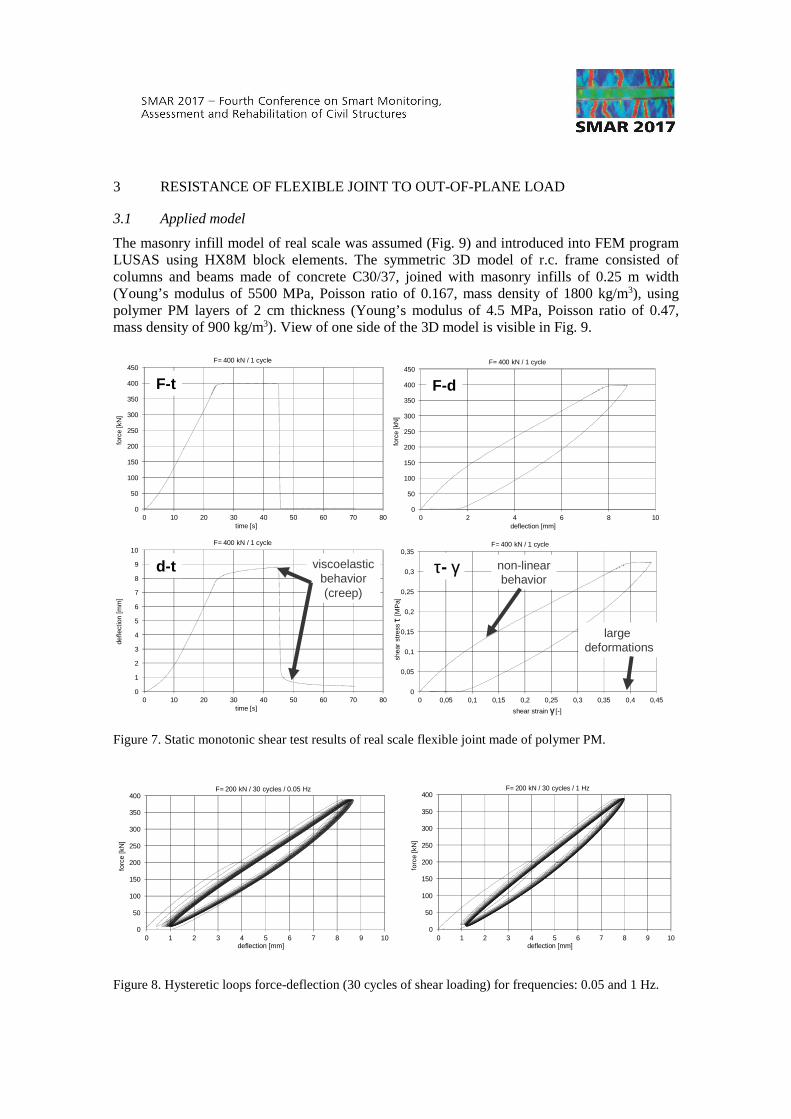
First, static monotonic loading up to 400 kN was applied. The maximum load was maintained for short time of 20 s and then the specimen was unloaded with data acquisition, to investigate rheological behavior of the joint (which is responsible for energy dissipation under cyclic loads). Obtained results are presented in Fig. 7 with stress-strain characteristic of simple shear in the Lagrange strain measure – comp. in Kwiecień et al. (2015). They indicate that full scale polymer PM flexible joint is able to withstand high loads and large deformations simultaneously. It can also redistribute stress and dissipate energy by visco-elastic and rheological mechanisms. Results indicate that the interface between the r.c. frame and masonry infill is able to carry horizontal shear forces in out-of-plane mode during earthquakes and redistribute shear deformations, thus keeping the shear stress extremely low.
Next, cyclic tests were carried out on the same specimen by repeating cyclic loading with various frequencies: 0.05, 0.1, 0.5 and 1 Hz, with the initial load of 200 kN and 30 cycles in the load range 10-390 kN. The obtained results in form of hysteretic loops (force-deflection) are presented in Fig. 8. They confirm that the proposed flexible joint is able to work in seismic areas under high loads and dissipate energy in visco-elastic mechanism. These results may be safely generalized to real cases of out of plane behavior of infills with load reversals (interfacial shear stress cycles around zero).
16 16 99 99 78
308 cm
78 78 76 76
F
3 RESISTANCE OF FLEXIBLE JOINT TO OUT-OF-PLANE LOAD
3.1 Applied model
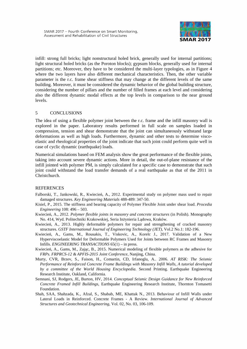
The masonry infill model of real scale was assumed (Fig. 9) and introduced into FEM program LUSAS using HX8M block elements. The symmetric 3D model of r.c. frame consisted of columns and beams made of concrete C30/37, joined with masonry infills of 0.25 m width (Young’s modulus of 5500 MPa, Poisson ratio of 0.167, mass density of 1800 kg/m3), using polymer PM layers of 2 cm thickness (Young’s modulus of 4.5 MPa, Poisson ratio of 0.47, mass density of 900 kg/m3). View of one side of the 3D model is visible in Fig. 9.
0
50
100
150
200
250
300
350
400
450
0 10 20 30 40 50 60 70 80
forc
e [k
N]
time [s]
F= 400 kN / 1 cycle
F-t
0
50
100
150
200
250
300
350
400
450
0 2 4 6 8 10
forc
e [k
N]
deflection [mm]
F= 400 kN / 1 cycle
F-d
0
1
2
3
4
5
6
7
8
9
10
0 10 20 30 40 50 60 70 80
defle
ctio
n [m
m]
time [s]
F= 400 kN / 1 cycle
viscoelasticbehavior(creep)
d-t
0
0,05
0,1
0,15
0,2
0,25
0,3
0,35
0 0,05 0,1 0,15 0,2 0,25 0,3 0,35 0,4 0,45
shea
r st
ress
τ[M
Pa]
shear strain γ [-]
F= 400 kN / 1 cycle
non-linearbehavior
largedeformations
τ- γ
Figure 7. Static monotonic shear test results of real scale flexible joint made of polymer PM.
0
50
100
150
200
250
300
350
400
0 1 2 3 4 5 6 7 8 9 10
forc
e [k
N]
deflection [mm]
F= 200 kN / 30 cycles / 0.05 Hz
0
50
100
150
200
250
300
350
400
0 1 2 3 4 5 6 7 8 9 10
forc
e [k
N]
deflection [mm]
F= 200 kN / 30 cycles / 1 Hz
Figure 8. Hysteretic loops force-deflection (30 cycles of shear loading) for frequencies: 0.05 and 1 Hz.
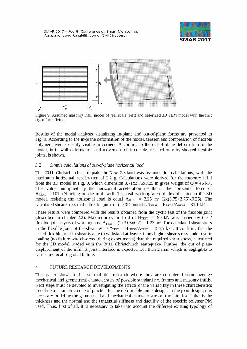
Figure 9. Assumed masonry infill model of real scale (left) and deformed 3D FEM model with the first eigen form (left).
Results of the modal analysis visualizing in-plane and out-of-plane forms are presented in Fig. 9. According to the in-plane deformation of the model, tension and compression of flexible polymer layer is clearly visible in corners. According to the out-of-plane deformation of the model, infill wall deformation and movement of it outside, resisted only by sheared flexible joints, is shown.
3.2 Simple calculations of out-of-plane horizontal load
The 2011 Christchurch earthquake in New Zealand was assumed for calculations, with the maximum horizontal acceleration of 2.2 g. Calculations were derived for the masonry infill from the 3D model in Fig. 9, which dimension 3.71x2.76x0.25 m gives weight of Q = 46 kN. This value multiplied by the horizontal acceleration results in the horizontal force of HREAL = 101 kN acting on the infill wall. The real working area of flexible joint in the 3D model, resisting the horizontal load is equal AREAL = 3.25 m2 (2x(3.75+2,76)x0.25). The calculated shear stress in the flexible joint of the 3D model is τREAL = HREAL/AREAL = 31.1 kPa.
These results were compared with the results obtained from the cyclic test of the flexible joint (described in chapter 2.3). Maximum cyclic load of HTEST = 190 kN was carried by the 2 flexible joint layers of working area ATEST = (2x3.08x0.2) = 1.23 m2. The calculated shear stress in the flexible joint of the shear test is τTEST = H TEST/ATEST = 154.5 kPa. It confirms that the tested flexible joint in shear is able to withstand at least 5 times higher shear stress under cyclic loading (no failure was observed during experiments) than the required shear stress, calculated for the 3D model loaded with the 2011 Christchurch earthquake. Further, the out of plane displacement of the infill at joint interface is expected less than 2 mm, which is negligible to cause any local or global failure.
4 FUTURE RESEARCH DEVELOPMENTS
This paper shows a first step of this research where they are considered some average mechanical and geometrical characteristics of possible standard r.c. frames and masonry infills. Next steps must be devoted to investigating the effects of the variability in these characteristics to define a parametric code of practice for the deformable joints design. In the joint design, it is necessary to define the geometrical and mechanical characteristics of the joint itself, that is the thickness and the normal and the tangential stiffness and ductility of the specific polymer PM used. Thus, first of all, it is necessary to take into account the different existing typology of
infill: strong full bricks; light nonstructural holed brick, generally used for internal partitions; light structural holed bricks (as the Poroton blocks); gypsum blocks, generally used for internal partitions; etc. Moreover, they have to be considered the multi-layer typologies, as in Figure 4 where the two layers have also different mechanical characteristics. Then, the other variable parameter is the r.c. frame shear stiffness that may change at the different levels of the same building. Moreover, it must be considered the dynamic behavior of the global building structure, considering the number of pillars and the number of filled frames at each level and considering also the different dynamic modal effects at the top levels in comparison to the near ground levels.
5 CONCLUSIONS
The idea of using a flexible polymer joint between the r.c. frame and the infill masonry wall is explored in the paper. Laboratory results performed in full scale on samples loaded in compression, tension and shear demonstrate that the joint can simultaneously withstand large deformations as well as high loads. Furthermore, dynamic and other tests to determine visco-elastic and rheological properties of the joint indicate that such joint could perform quite well in case of cyclic dynamic (earthquake) loads.
Numerical simulations based on FEM analysis show the great performance of the flexible joints, taking into account severe dynamic actions. More in detail, the out-of-plane resistance of the infill jointed with polymer PM, is simply calculated for a specific case to demonstrate that such joint could withstand the load transfer demands of a real earthquake as that of the 2011 in Christchurch.
REFERENCES Falborski, T., Jankowski, R., Kwiecień, A., 2012. Experimental study on polymer mass used to repair
damaged structures. Key Engineering Materials 488-489: 347-50. Kisiel, P., 2015. The stiffness and bearing capacity of Polymer Flexible Joint under shear load. Procedia
Engineering 108: 496 – 503. Kwiecień, A., 2012. Polymer flexible joints in masonry and concrete structures (in Polish). Monography
No. 414, Wyd. Politechniki Krakowskiej, Seria Inżynieria Lądowa, Kraków. Kwiecień, A., 2013. Highly deformable polymers for repair and strengthening of cracked masonry
structures. GSTF International Journal of Engineering Technology (JET), Vol.2 No.1: 182-196. Kwiecień, A., Gams, M., Rousakis, T., Viskovic, A., Korelc J., 2017. Validation of a New
Hyperviscoelastic Model for Deformable Polymers Used for Joints between RC Frames and Masonry Infills. ENGINEERING TRANSACTIONS 65(1) – in press.
Kwiecień, A., Gams, M., Zając, B., 2015. Numerical modeling of flexible polymers as the adhesive for FRPs. FRPRCS-12 & APFIS-2015 Joint Conference, Nanjing, China.
Murty, CVR, Brzev, S., Faison, H., Comartin, CD, Irfanoglu, A.. 2006. AT RISK: The Seismic Performance of Reinforced Concrete Frame Buildings with Masonry Infill Walls, A tutorial developed by a committee of the World Housing Encyclopedia. Second Printing. Earthquake Engineering Research Institute, Oakland, California.
Semnani, SJ, Rodgers, JE, Burton, HV, 2014. Conceptual Seismic Design Guidance for New Reinforced Concrete Framed Infill Buildings, Earthquake Engineering Research Institute, Thornton Tomasetti Foundation.
Shah, SAA, Shahzada, K., Afzal, S., Shabab, ME, Khattak N., 2013. Behaviour of Infill Walls under Lateral Loads in Reinforced. Concrete Frames - A Review. International Journal of Advanced Structures and Geotechnical Engineering, Vol. 02, No. 03, 106-109.