Embed Size (px)
Citation preview
SECTION 6A
ENGINE MECHANICAL
INDEX
General Description ...... . ..... . ...... .. .. . .
Service Operations . .. .
Carburetor Removal. ... . . .. . . . ......... . .
Engine Sheet Met.~I . . .. . ... . . .. .. .. . . .. . .
Upper Shroud .. . .. . ....... .. . . ........ .
Front Shield .... . . ..... ..... . . . . ... . .. .
Lower Shroud . ... .. .. . . .. .... .... .... . .
Exhaust Duct .. . .. . . .. . ..... . . . .... .. . .
Front Shroud .. . . . . ............ ..... .. .
Page 6A-I
6A-I
6A-l
6A-I
6A-I
6A-3
6A-4 6A-5
6A-5
Exhaust Valves .... . Valve Push Rods .... . Valve Lifters Replacement .. .. .......... . . Valve Lash Adjustment-Engine Running . . . Blower Bearing Replacement ........... . Oil Pressure and Engine Temperature Sending Switches ..... Oil Filter Replacement (A j C vehicles) .... . . Cylinder Heads . . . . . . . . . . . . . . .. ... . . . Rear Main Bearing . .. . ......... . ... . .. . . . Supercharged Engine ..... ....... . . ..... . . .
Page 6A-5 6A-6 6A-6 6A-6 6A-6
6A-7 6A-7 6A-7 6A-8 6A-9
GENERAL DESCRIPTION The 1963 Corvair engine basic design is the same as
in 1961 with improvements incorporated as follows:
1. A new automatic choke system pennits automatically controlled carburetion during warmup. (See Section 9 for details.)
2. Engine shrouding has been revised to accomm<>date these changes and provide access to the choke thermostat on the lower side of the head and to
oil pressure and engine temperature sending units.
3. Starting mid 1961 and carried over to 1963, Monza 9-1 compression ratio engines use a cylinder head with a revised combustion chamber consisting of filled in roof surfaces around the valves and spark plug holes.
4. A new distributor provides easier servicing (see Section 8).
SERVICE OPERATIONS The following service operations represent only
changes or additions to the 1961 Corvair Shop Manual Service Operations.
CARBURETOR REMOVAL When it is necessary to remove a carburetor to gain
access to another part, remove both carburetors and cross-shaft as an assembly in order to maintain the present carburetor synchronization. When carburetors are reinstalled, however, synchronization should be checked. The procedure is as follows:
1. Remove air cleaners and cross-tube.
2. Disconnect accelerator rod from cross-shaft and distributor spark hose at right carburetor.
3. Disconnect choke control rods at choke shaft levels and fuel lines at carburetor.
4. Remove two hold-down nuts at each carburetor and lift carburetors and cross-shaft out as an assembly (fig. 6A-2).
5. Reverse above procedure to install and then check synchronization (outlined in Section 7) .
ENGINE SHEET METAL COMPONENTS Engine sheet metal has been changed to accommo
date the new automatic choke (fig. 6A-3). Their service procedures change as follows:
Upper Shroud Assembly
Removal
1. Remove air cleaners assemblies and supports. 2. Disconnect fuel lines at carburetors and at fuel
ENGINE MECHANICAL 6A-2
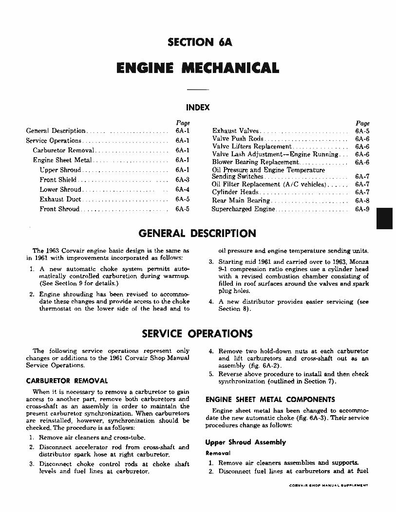
Fig. 6A-l-Enllne Compartment
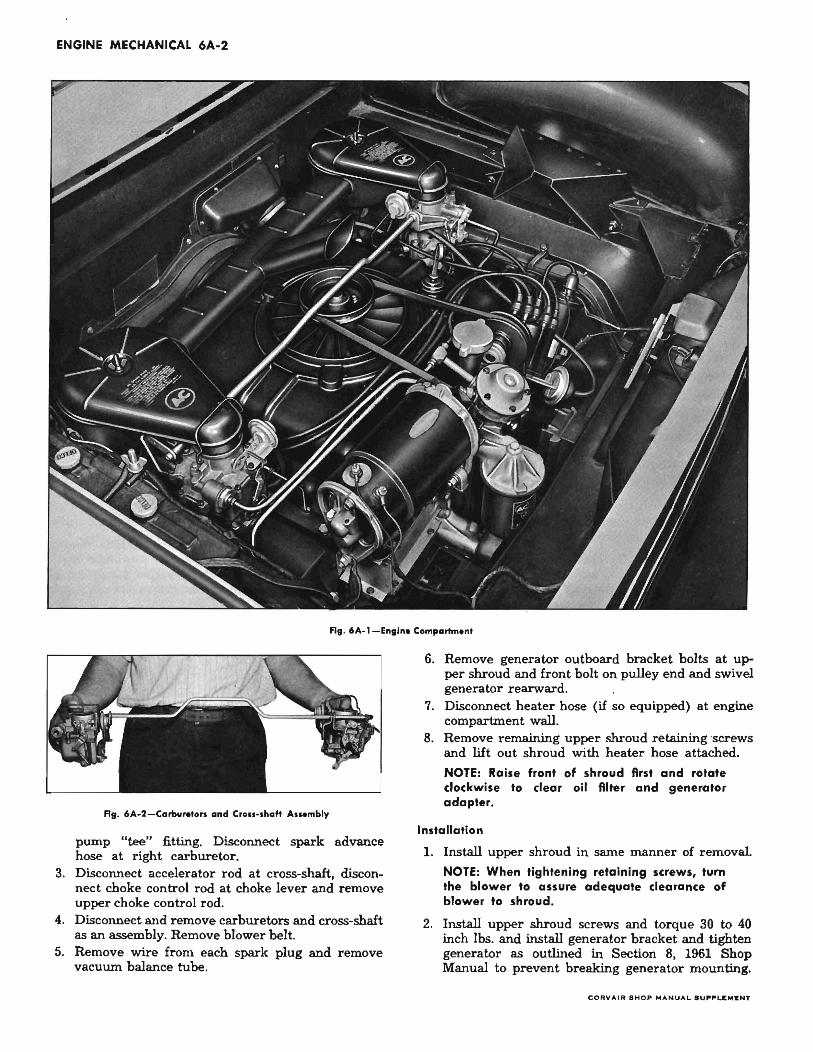
Fig. 6A-2-Camur.tors and CrOll-shaft Ass.mbly
pump "tee" fitting. Disconnect spark advance hose at right carburetor.
3. Disconnect accelerator rod at cross-shaft, disconnect choke control rod at choke lever and remove upper choke control rod.
4. Disconnect and remove carburetors and cross-shaft as an assembly. Remove blower belt.
5. Remove wire from each spark plug and remove vacuum balance tube.
6. Remove generator outboard bracket bolts at upper shroud and front bolt on pulley end and swivel generator rearward.
7. Disconnect heater hose (if so equipped) at engine compartment wall.
8. Remove remaining upper shroud retaining 'screws and lift out shroud with heater hose attached.
NOTE: Raise front of shroud first and rotate clockwise to clear oil filter and generator adapter.
Installation
1. Install upper shroud in same manner of removal.
NOTE: When tightening retaining screws, turn the blower to assure adequate clearance of blower to shroud.
2. Install upper shroud screws and torque 30 to 40 inch lbs. and install generator bracket and tighten generator as outlined in Sectiol' 8, 1961 Shop Manual to prevent breaking generator mounting.
CO RY"IR . HO~ MANUA L . U .... LEMENT
ENGINE MECHANICAL 6A-3
, 33
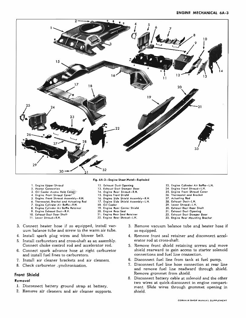
Fig . 6A-3-Engine Sh ... Metal-Exploded
1. Engine Upper Shroud 12. Exhaust Duct Opening 23 . Engine Cylinder Air Boffle-l.H. 2 .. , Engine Front Shroud-l.H. 2. Healer Connection
3 . Oil Cooler Access Hole CO~ij; ' ... Engine Front Shroud Coyel"
13. Exhaust Duci Damper Door , .. . Engine Reor Shroud-R.H. IS. Engine Front Shield
25. Engine Front Shroud Cover 26. Thermostat and Brodet
5. Engine Front Shroud Assembly-R.H. 16. Engine Side Shield Assembly-R.H. 27. Actuating Rod 6. Thermostat, Brocket ond Actuat ing Rod 17. Engine Side Shield Assembly-l.H . 28. Exhaust Duel-l.H . 7. Engine Cylinder Air SoAle-R.H. 18. Oil Cooler 29. lower Shroud-l.H. 8. Engine Cylinder Air Boffle Retainer 19. Engine Reor Center Shield 30. Exhouit Duct Door Shaft 9 . Engine bhou,' Duel - I .H. 20. Engine Reor 5eol 31. Exhoust Duel Opening
10. hhoU5' Oucl Door Shaft 21. Engine Reor Seol Reloiner 32 . Exhoust Duct Domper Door 11. lower Shroud-R.H. 22 . Engine Rear Shroud-l.H. 33 . Engine Rear Mounting Brockel
3. Connect heater hose if so equipped, install vacuum balance tube and screw to the wann air tube.
4. Install spark plug wires and blower belt. S. Install carburetors and cross-shaft as an assembly.
Connect choke control rod and accelerator rod. 6. Connect spark advance hose at right carburetor
and install fuel lines to carburetors. 7. Install air cleaner brackets and air cleaners. 8. Check carburetor .:ynchronization.
Front Shield Removal
1. Disconnect battery ground strap at battery. 2. Remove air cleaners and air cleaner supports.
3. Remove vacuum balance tube and heater hose if so equipped.
4. Remove front seal retainer and disconnect accelerator rod at cross-shaft.
S. Remove front shield retaining screws and move shield rearward to gain access to starter solenoid connections and fuel line connection.
6. Disconnect fuel line from tank at fuel pump. 7. Disconnect fuel line hose connection at rear line
and remove fuel line readward through shield. Remove grommet from shield.
8. Disconnect battery cable at solenoid and the other two wires at quick-disconnect in engine compartment. Slide wires through grommet opening in shield.
C ORVAIR SHOP MANUAL SUPPLEMENT
ENGINE MECHANICAL 6A-4
9. Remove shield over accelerator rod and dust boot.
Installation
Reverse the Removal procedure to install.
Lower Shroud IAn interim change in 1961 and 19621
The lower shroud is a separate piece from the exhaust duct and damper assembly. The exhaust duct damper thermostat is in the same location and is adjusted in the same manner. The lower shroud, however, may be removed without the duct and damper assembly to service the oil pressure and engine temperature sending units and the choke stove unit on the 1963 engines.
The procedure is as follows for both right and left sides.
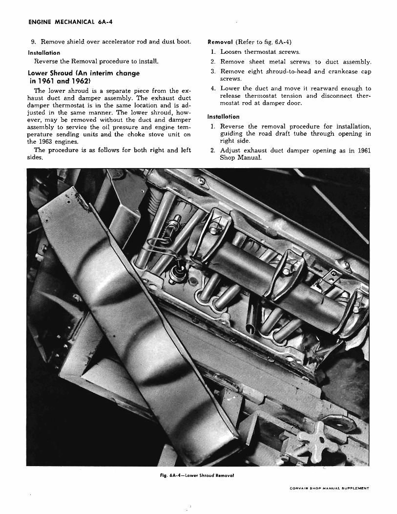
Removal (Refer to fig. 6A-4)
1. Loosen thermostat screws.
2. Remove sheet melal screws 10 duct assembly.
3. Remove eight shroud-Io-head and crankcase cap screws.
4. Lower the duct and move it rearward enough to re lease thermostat tension and disconnect thermostat rod at damper door.
Installation
1. Reverse the removal procedure for installation, guiding the road draft tube through opening in right side.
2. Adjust exhaust duct damper opening as in 1961 Shop Manual.
Fig. 6A-4-Low.r Shroud •• moval
COAVArR SHOP MA. .... UAL SUPPLI[MENT

Lower Shroud (Interim Change 1962 and 19631
The lower shroud assembly consists of the 1962 shroud with thermostat bracket and heat shield riveted in place instead of bolt attachment.
To replace either the shroud, shield or bracket remove assembly as outlined above, remove thermostat assembly, then drill out the rivets with a %/' drill and reassemble required new parts using '4-20 .bolt and self-locking nut.
Exhaust Dud Damper Thermostat Replace
1. Remove lower shroud assembly.
2. Remove thermostat rod from thermostat.
3. Remove stop bolt then lift thermostat out of bracket.
4. Reverse removal to install.
Exhaust Dud
(Refer to fig. 6A-31
Removal
1. Remove lower shroud assembly.
2. Remove engine rear seal and retainer.
3. On the left duct remove screws at oil cooler and rear center shield. On the right duct remove coil and mulHer bracket.
4. Remove remaining screws to duct and remove duct assembly.
--r' I I I
...-...-......-
ENGINE MECHANICAL 6A-5
NOTE: On Greenbrier or Lakewood Station Wagons or Vans, It Is necessary to drain the 011 and remove the 011 filler tube to remove duct.
Installation
1. Reverse removal procedure for installation.
2. Check adjustment of duct damper.
Front Shroud (Refer to fig. 6A-51
Removal
1. Remove lower shroud.
2. Remove exhaust manifold.
3. Remove three screws from front shield in upper compartment.
4. On right side remove two bolts holding exhaust muftler shield.
5. Remove heater duct hoses if direct air heater equipped.
6. Remove remaining bolts and remove front shroud assembly. (On left side one bolt is inside heater duct opening.) '0
Installation r
1. Reverse removal procedure to insta1l. 2. Check adjustment on exhaust duct damper.
EXHAUST VALVES
The 1962 turbocharged Spyder engine and all 1963 Corvair engines use exhaust valves with a 4-bead groove type key locks (fig. 6) installed in the same manner as previous one-groove type.
..
•
SINGLE GROOVE LOCK
BEAD LOCK DESIGN
fit. 6,.-6-..... Lod< Eahauot Vo'"
CORYAIIt .HO~ MANUAL ~UP'PU"KNT
ENGINE MECHANICAL 6A-6
A mid-year change in 1961, carried over, replaces tapered stem exhaust valves with straight stem valves and releases valve stems of .003", .010" and .020" oversizes for service. Tool J-5830-5 is the new .020" oversize reamer.
1. Micrometer and Telescope Gauge
Intake valve stem to bore clearance should be .001" to .0027" (new) and .004" (worn) while exhaust stem clearance should be .0014" to .0029" (new) and .006" (worn). Using a micrometer and a suitable telescope hold gauge, check the diameter of the valve stem 1" from the stem tip. Insert telescope hold gauge in valve guide bore, measuring at the port end. Subtract reading of valve stem diameter from valve guide bore port end diameter to obtain stem to bore clearance. If clearance is not within above worn limits, use next oversize valve and ream valve bore to obtain proper clearance.
2. Using a Dial Indicator
Intake valve stem to bore clearance should be .001" to .0027" (new) and .004" (worn) while exhaust stem clearance should be .0014" to .0029" (new) and .006" (worn). Using a Last Word Indicator, clamp the indicator on one side of cylinder head rocker cover gasket rail, arranging the indicator so that movement of the valve stem from side to side (crosswise to the head) will c,ause a direct movement of the indicator stem. The indicator stem must contact the side of the valve stem just above the cylinder guide. With the valve head dropped about y,.' off the valve seat, move the
.. of the valve from side to side with light pressure W btain the clearance. By trying new .valves in the 01 bores it can be determined whether the valves
' should be replaced, or the bores reamed and oversize valves installed.
Valve Push Rods
Push rods on Corvair engines must be installed with side oil hole (paint marked end) to rocker arm.
VALVE LIFTERS
The new lower shroud for 1962 and 1963 makes it easier to remove or replace valve lifters. Remove lower shroud as previously outlined and then follow 1961 shop manual outline to complete the job.
New or rebuilt valve lifters should be refilled with oil before installation to the engine. This can be accomplished by submerging the lifter in a can of engine oil and working the lifter plunger up and dow~ ~veral times. .~.
VALVE LASH ADJUSTMENT,ENGINE RUNNING
. After the engine has been normalized, remove \lIve cover and install a reworked valve cover
(cut the top out of a used valve cover) and gasket on cylinder heads to prevent oil from running out.
2. With the engine running at idle, back off valve rocke r arm nut until the valve rocker arm starts to clatter.
3. Turn rocker arm nut down slowly until the clatter just stops. This is the zero lash position.
4. Turn nut down V. additional turn and pause 10 seconds until engine runs smoothly. Repeat additional '14 turns, pausing 10 seconds each time, until nut has been turned down 1 full turn from the zero lash position.
NOTE: This 1 tUrn pre-load adjustment must be done slowly to allow the lifter to adjust itself to prevent the possibility of interference, between the inlet valve head and top of piston, which might result in internal damage and/or bent push rods. Noisy lifters should be replaced.
5. Repeat Steps 2, 3 and 4 to adjust the rest of the valves.
6. Remove reworked cover and install valve cover, using new gasket.
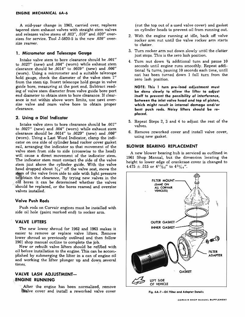
BLOWER BEARING REPLACEMENT
A new blower bearing hub is serviced as outlined in 1961 Shop Manual, but the dimension locating the height to lower edge of crankcase cover is changed to 4.475 ± .015 or 4' %," to 43Vu/'.
FILTER MOUNTv.l ISAME ON All CORVAll . VEHlClESI . . /I, ~. •
i/' L~ l@J~a \
OUTER GASKET
INNER GASKET
LEFT SIDE OF VEHICLE
I - . I ,
FILTER ADAPTER
Fig. 6A~7-011 Filter and Adapter Detail,
co,.V ArR SHOP MAN UAL S UPPLI!:MI'.:NT
OIL FILTER REPLACEMENT (AIR CONDITIONED VEHICLES'
(Refer to fig. 6A-7' 1. Remove bolt through generator-oil filter adapter
plate to adapter elbow while supporting oil filter and elbow.
2. Remove oil filter and elbow as an assembly to avoid oil spillage into engine compartment.
3. Remove filter mounting bolt and separate elbow from filter.
4. Discard filter and clean the elbow.
5. Replace all gaskets and use new filter.
6. Reverse Steps 1-3 to install.
CYLINDER HEADS
Cylinder head service procedures change from 1961 only because the automatic choke control rod passes through the head to reach the thermostat and must be removed before the head can be removed.
The specification table in Section 12 points out changes from 1961 engines.
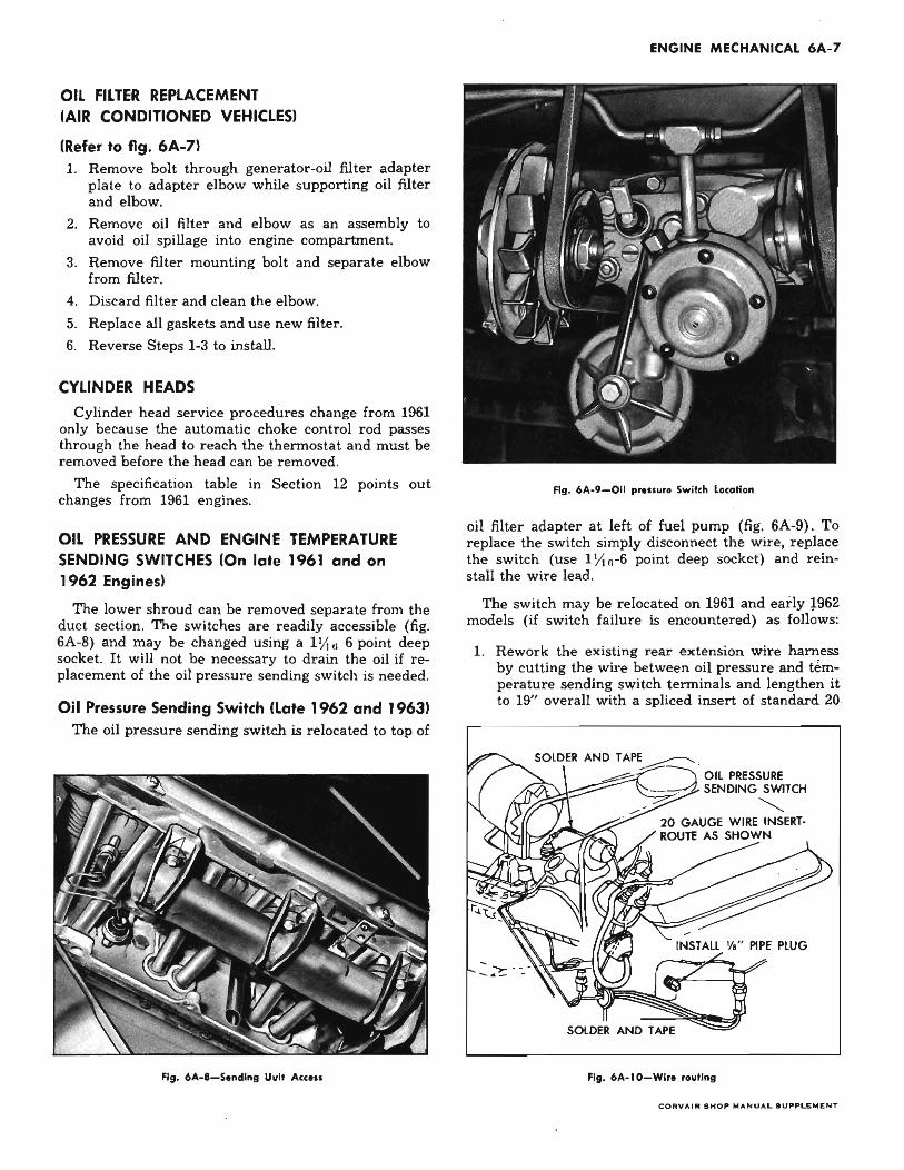
OIL PRESSURE AND ENGINE TEMPERATURE SENDING SWITCHES (On late 1961 and on 1962 Engines'
The lower shroud can be removed separate from the duct section. The switches are readily accessible (fig. 6A-B) and may be changed using a 1 y, ,, 6 point deep socket. It will not be necessary to drain the oil if replacement of the oil pressure sending switch is needed.
Oil Pressure Sending Switch (Late 1962 and 1963' The oil pressure sending switch is relocated to top of
Fig. 6A-a-Sendln, Uuit Access
ENGINE MECHANICAL 6A-7
Fig_ 6A-9-0il p ... ssur. Switch location
oil filter adapter at left of fuel pump (fig. 6A-9). To replace the switch simply disconnect the wire, replace the switch (use 1 YI n-6 point deep socket) and reinstall the wire lead.
The switch may be relocated on 1961 and early 1962 models (if switch failure is encountered) as follows:
1. Rework the existing rear extension wire harness by cutting the wire between oil pressure and temperature sending switch terminals and lengthen it to 19" overall with a spliced insert of standard 20·
SOlDE~R AND TAPE • -----." Oil PRESSURE
'---7.-1. SENDING SWITCH
~ 20 GAUGE WIRE INSERTROUTE AS SHOWN
SOLDER AND TAPE
fig. 6A-l0-Wi,.. routing
CORYAIR SHOP MANUAL SUP,.LEMr:NT
ENGINE MECHANICAL 6A-B
gauge plastic insulated wire similar to the existing wire. Solder and tape both joints and route the wire as shown in Figure 6A-lO.
2. Remove existing 'AI" pipe plug from oil filter adapter (fig. 6A-8) and install it in hole formerly occupied by the faulty oil pressure sending switch (use sealer on threads) .
3. InstaIl new switch in oil filter adapter (fig. 6A-9) and torque to 8-12 ft. lbs., then bend terminal to 45° and connect rerouted wire lead.
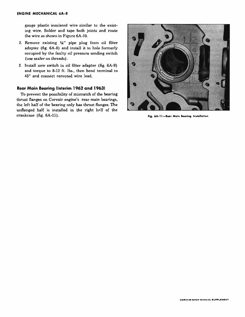
Rear Main Bearing !Interim 1962 and 19631 To prevent the possibility of mismatch of the bearing
thrust flanges on Corvair engine's rear main bearings, the left half of the bearing only has thrust flanges. The unflanged half is installed in the right h.lf of the crankcase (fig. 6A-ll) . fi. _ 6A·l1 -I .. , Moin &.on", IndollaHon
COflYAIIt 8HOl" MANUAL aU,.,.UMKNT
ENGINE MECHANICAL 6A-9
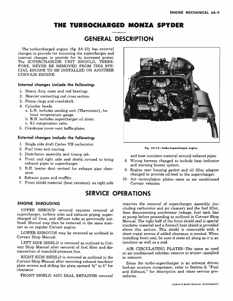
THE TURBOCHARGED MONZA SPYDER
GENERAL DESCRIPTION The turborcharged engine (fig. 6A-12) has external
changes to provide for mounting the supercharger and internal changes to provide for its increased power. The SUPERCHARGER UNIT SHOULD, THEREFORE, NEVER BE REMOVED FROM THIS SPECIAL ENGINE TO BE INSTALLED ON ANOTHER CORV AIR ENGINE.
Internal changes include the following:
1. Heavy duty main and rod bearings. 2. Heavier connecting rod cross section. 3. Piston rings and crankshaft. 4. Cylinder heads.
a. L .H. includes sending unit (Thermister) , for head temperature gauge.
b. R.H. includes supercharger oil drain. c. 8:1 compression ratio.
5. Crankcase cover vent baffle plates.
External changes include the following:
1. Single side draft Carter YH carburetor. 2. Fuel lines and routing. 3. Distributor assembly and timing tab. 4. Front and right side seal shield revised to bring
exhaust pipes to supercharger. 5. R.H. heater duct revised for exhaust pipe clear
ance . 6. Exhaust pipes and muffler. 7. Front shield material (heat resistant) on right side
Fig. 6A.12-T",bo-Supercharged engine
and heat insulator material around exhaust pipes. 8. Wiring harness changed to include heat indicator
and warning buzzer system. 9. Engine rear housing gasket and oil filter adapter
changed to provide oil feed to the supercharger. 10. Air recirculation plates-same as air conditioned
Corvair vehicles.
SERVICE OPERATIONS ENGINE SHROUDING
UPPER SHROUD removal requires removal of supercharger, turbine inlet and exhaust piping, supercharged oil lines, and diffuser tube as previously outlined. Shroud may then be removed in the same manner as on regular Corvair engine.
LOWER SHROUDS may be removed as outlined in Corvair Shop Manual.
LEFT SIDE SHIELD is removed as outlined in Corvair Shop Manual after removal of fuel filter and disconnection of manifold pressure line.
RIGHT SIDE SHIELD is removed as outlined in the Corvair Shop Manual after removing exhaust insulator plate screws and sliding the plate upward 'h" to 1" for clearance.
FRONT SHIELD AND SEAL RETAINER removal
requires the removal of supercharger assembly (including carburetor and air cleaner) and the fuel filter, then disconnecting accelerator linkage, fuel tank line at pump before proceeding as outlined in Corvair Shop Manual. The right half of the front shield seal is special insulator material and a firewall heat shield is provided above this section. This shield is removable with 4 sheet metal screws if added clearance is needed. When installing front seal, be sure it seats all along as it is an insulator as well as a seal.
AIR CIRCULATING PLATES-The same as used on air conditioned vehicles-remove in winter-installed in summer.
Since the turbo-supercharger is an exhaust driven fuel-air mixture compressor, refer to Section 9, "Fuel and Exhaust," for description and other service procedures.
CORVAIR SHOP MANUAL SUPPLEMENT