Embed Size (px)
Citation preview
EI
BODY AND ELECTRICAL
ENGINE IMMOBILISER
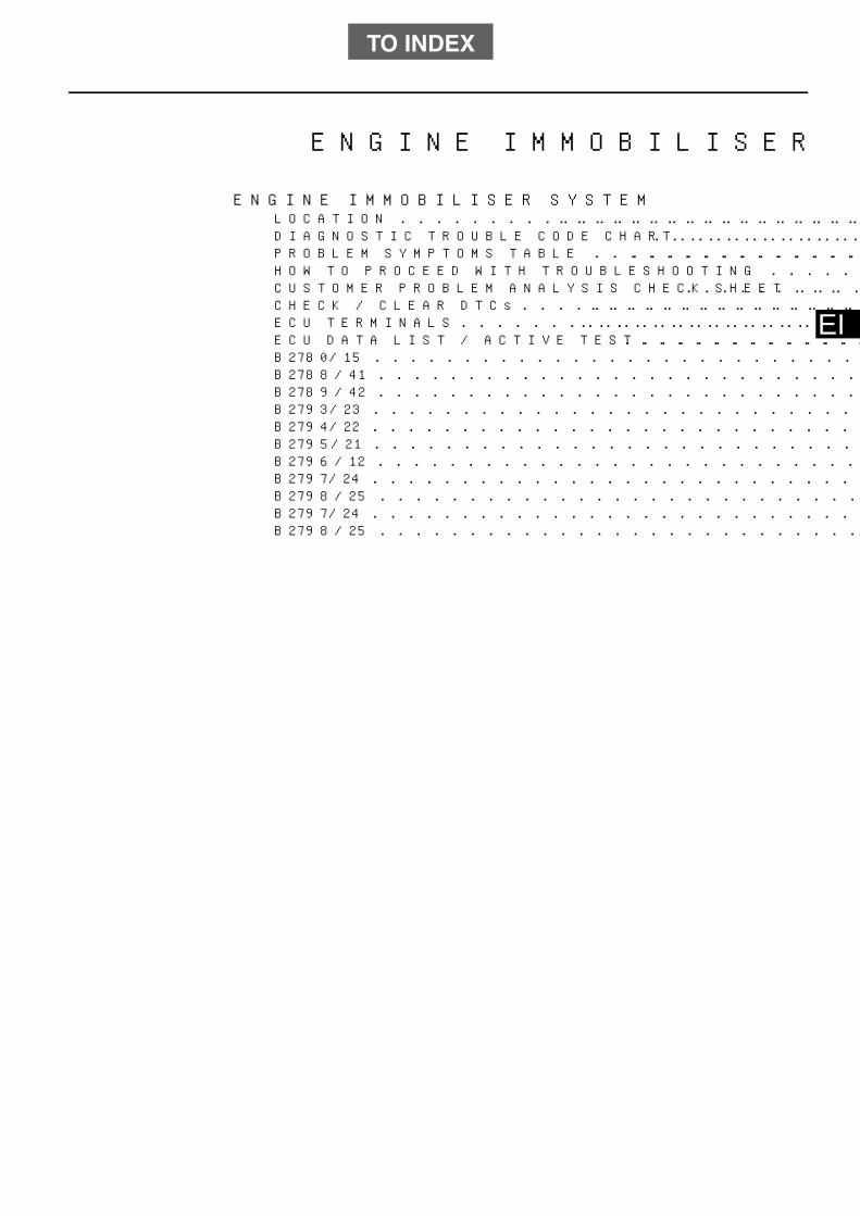
ENGINE IMMOBILISER SYSTEMLOCATION . . . . . . . . . . . . . . . . . . . . . . . . . . . . . . . . . . . . . . . . . . . . . . . . . . . . . . . EI-1DIAGNOSTIC TROUBLE CODE CHART . . . . . . . . . . . . . . . . . . . . . . . . . . . . . . . . EI-1PROBLEM SYMPTOMS TABLE . . . . . . . . . . . . . . . . . . . . . . . . . . . . . . . . . . . . . . EI-2HOW TO PROCEED WITH TROUBLESHOOTING . . . . . . . . . . . . . . . . . . . . . . . . EI-2CUSTOMER PROBLEM ANALYSIS CHECK SHEET . . . . . . . . . . . . . . . . . . . . . . EI-5CHECK / CLEAR DTCs . . . . . . . . . . . . . . . . . . . . . . . . . . . . . . . . . . . . . . . . . . . . . EI-6ECU TERMINALS . . . . . . . . . . . . . . . . . . . . . . . . . . . . . . . . . . . . . . . . . . . . . . . . . . EI-7ECU DATA LIST / ACTIVE TEST . . . . . . . . . . . . . . . . . . . . . . . . . . . . . . . . . . . . . EI-9B2780/15 . . . . . . . . . . . . . . . . . . . . . . . . . . . . . . . . . . . . . . . . . . . . . . . . . . . . . . . . EI-10B2788/41 . . . . . . . . . . . . . . . . . . . . . . . . . . . . . . . . . . . . . . . . . . . . . . . . . . . . . . . . EI-13B2789/42 . . . . . . . . . . . . . . . . . . . . . . . . . . . . . . . . . . . . . . . . . . . . . . . . . . . . . . . . EI-13B2793/23 . . . . . . . . . . . . . . . . . . . . . . . . . . . . . . . . . . . . . . . . . . . . . . . . . . . . . . . . EI-15B2794/22 . . . . . . . . . . . . . . . . . . . . . . . . . . . . . . . . . . . . . . . . . . . . . . . . . . . . . . . . EI-16B2795/21 . . . . . . . . . . . . . . . . . . . . . . . . . . . . . . . . . . . . . . . . . . . . . . . . . . . . . . . . EI-17B2796/12 . . . . . . . . . . . . . . . . . . . . . . . . . . . . . . . . . . . . . . . . . . . . . . . . . . . . . . . . EI-18B2797/24 . . . . . . . . . . . . . . . . . . . . . . . . . . . . . . . . . . . . . . . . . . . . . . . . . . . . . . . . EI-18B2798/25 . . . . . . . . . . . . . . . . . . . . . . . . . . . . . . . . . . . . . . . . . . . . . . . . . . . . . . . . EI-18B2797/24 . . . . . . . . . . . . . . . . . . . . . . . . . . . . . . . . . . . . . . . . . . . . . . . . . . . . . . . . EI-21B2798/25 . . . . . . . . . . . . . . . . . . . . . . . . . . . . . . . . . . . . . . . . . . . . . . . . . . . . . . . . EI-21
TO INDEX
EI–1 ENGINE IMMOBILISER - ENGINE IMMOBILISER SYSTEM
EI
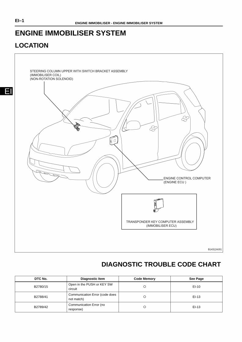
BODY AND ELECTRICALENGINE IMMOBILISERENGINE IMMOBILISER SYSTEMLOCATION
DIAGNOSTIC TROUBLE CODE CHART
STEERING COLUMN UPPER WITH SWITCH BRACKET ASSEMBLY
(IMMOBILISER COIL)
(NON-ROTATION SOLENOID)
ENGINE CONTROL COMPUTER
(ENGINE ECU )
TRANSPONDER KEY COMPUTER ASSEMBLY
(IMMOBILISER ECU)
B143124J01
DTC No. Diagnostic Item Code Memory See Page
B2780/15Open in the PUSH or KEY SW circuit
EI-10
B2788/41Communication Error (code does not match)
EI-13
B2789/42Communication Error (no response)
EI-13

ENGINE IMMOBILISER - ENGINE IMMOBILISER SYSTEM EI–2
EIPROBLEM SYMPTOMS TABLE
HOW TO PROCEED WITH TROUBLESHOOTING
HINT:(See page EI-5)
B2793/23Immobiliser: Communication Malfunction 1
EI-15
B2794/22Immobiliser: Communication Malfunction 2
EI-16
B2795/21Main Key ID Code Does Not Match
EI-17
B2796/12 Main Key Or Coil Malfunction EI-18
B2797/24Immobiliser: Communication Malfunction 4
EI-21
B2798/25Immobiliser: Communication Malfunction 5
EI-21
DTC No. Diagnostic Item Code Memory See Page
Symptom Suspected Area See Page
Engine does not start
1. Transponder keyEI-15EI-16EI-18
2. Engine control computer (engine ECU) EI-13
3. Transponder key computer assembly
EI-10EI-13EI-16EI-18EI-21
4. Steering column upper with switch bracket assembly
EI-10EI-16EI-18EI-21
5. Wire harness
EI-10EI-13EI-18EI-21
6. Combination meter assembly EI-10
1 VEHICLE BROUGHT TO WORKSHOP
2 CONDUCT CUSTOMER PROBLEM ANALYSIS AND CHECK SYMPTOMS

EI–3 ENGINE IMMOBILISER - ENGINE IMMOBILISER SYSTEM
EI
HINT:(See page ES-8)(a) Check for DTCs of the EFI system using the DS-II.
B
A
(a) Using the DS-II, check for DTCs (see page EI-1). Record any DTCs.(b) Delete the DTCs.(c) Reproduce the symptoms based on the recorded code, and check if
the same DTC is output.
B
A
(a) Check if the symptom is listed in problem symptoms table (see pageEI-2)
B
A
(a) ECU DATA LIST / ACTIVE TEST (see page EI-9)(b) ECU terminals (See page EI-7)
3 CHECK FOR DTCs OF EFI (engine control system)
Result Proceed to
DTC is not output A
DTC is output B
GO TO ENGINE CONTROL SYSTEM
4 CHECK FOR DTCs OF IMB (ENGINE IMMOBILISER SYSTEM)
Result Proceed to
DTC is not output A
DTC is output B
GO TO TROUBLESHOOTING FOR EACHOUTPUT DTC
5 PROBLEM SYMPTOMS TABLE
Result Proceed to
Symptom is not listed in problem symptoms table A
Symptom is listed in problem symptoms table B
GO TO INSPECTION PROCEDURE 9
6 PERFORM TROUBLESHOOTING BASED ON PROBLEM SYMPTOM

ENGINE IMMOBILISER - ENGINE IMMOBILISER SYSTEM EI–4
EI
7 CHECK, REPAIR OR REPLACE
END

EI–5 ENGINE IMMOBILISER - ENGINE IMMOBILISER SYSTEM
EI
CUSTOMER PROBLEM ANALYSISCHECK
ENGINE IMMOBILISER SYSTEM Check Sheet Date vehicle brought in
/ /
Customer’ License Plate No.
VINModel
Engine Type Odometer Reading
Date Problem First Occurred / / :Hour of the day ____AM/PM
Problem descriptionStarting Trouble Security Indicator Illumination Malfunction
Additional key registration not possible Others ( )
Frequency Problem OccursUser ( Constant Frequent Occasional One time only )
During dealer check ( Constant Frequent Occasional One time only No longer occurs )
Temperature and weather conditiions when problem occurred 1) Temperature : ( Approx. ( )°C , 2) Weather : Clear Cloudy Rainy Snowy
Tendency to occur Morning driving Restarting the vehicle after driving approx. ( ) hours Others
When having starting trouble
did the vehicle start with another registered key?
When IG ON, does the security indicator turn off?
Does the engine crank normally?
Is another key attached to the key being used?
Detailed check results
when problem occurs
Immobiliser system DTC ( )
EFI system DTC ( )
Previous DTC ( )
History of changed problem parts
Installed accessory partsEngine starter (genuine parts / others) Smart system
Car navigation (genuine parts / others)
Other specified items
Written by Inspector’
Description of symptoms
First registration year 20 __ / /
s name
s Name
YES NO
YES NO
YES NO
YES NO
B143390

ENGINE IMMOBILISER - ENGINE IMMOBILISER SYSTEM EI–6
EI
CHECK / CLEAR DTCs
1. PREPARE FOR INSPECTION (a) Move the shift lever to the P position.(b) Turn off the air conditioning.
2. CHECK DTCs (using DS-II)(a) Connect the DS-II to the DLC.(b) Following the prompts on the screen, select DIAGNOSIS / IMB /
DIAGNOSTIC CODE to check DTCs.HINT:• If the check engine warning light remains on, wire harness
may have a short (or pinched) or the engine controlcomputer (engine ECU) may be malfunctioning.
• If the DS-II does not display DTCs or indicate the normalcondition, and the indicator light does not flash, there maybe an open in the TC circuit between the DLC connecterand each ECU or the engine control computer (engine ECU)may be malfunctioning.
3. CHECK DTCs (using the security indicator light)NOTICE:Turn the ignition switch to the ON position before reading theDTCs, and check that the security indicator light is flashing. (a) Turn the ignition switch off.
(b) Using the diagnosis check wire, short terminals 13 (ECUT) and4 (E) of the DLC.SST 09843-18040NOTICE:• Do not connect diagnosis check wire No. 2 to the wrong
terminals. Doing so may cause malfunctions. • Use only dedicated diagnosis check wire.
(c) Turn the ignition switch to the ON position, and count thenumber of flashes of the security indicator light.
HINT:• If the indicator light does not indicate a DTC (light does not
come on), there may be an open in the TC terminal or thecomputer may be malfunctioning.
• If the security indicator light remains on, the wire harnessmay have a short circuit (pinched) or the computer may bemalfunctioning.
E
ECUT
B141833
Normal Abnormal (codes 21 and 41 are output)
0.25 seconds
ON
OFF
ON
OFF
4 seconds 2.5 seconds
Code 41
4 seconds
Repeated
0.5 seconds0.5 seconds
Code 21
1.5 seconds
0.5 seconds
B141832

EI–7 ENGINE IMMOBILISER - ENGINE IMMOBILISER SYSTEM
EI
• If an irrelevant DTC is output, the computer may bemalfunctioning.
(d) Remove the diagnosis check wire.
4. CLEAR DTCs(a) Using the DS-II, following the prompts on the screen, select
CHECK DTC and CLEAR to clear the DTCs.NOTICE:• If the DTCs cannot be cleared, turn the ignition switch
off, then perform this procedure again.• Selecting CLEAR on the ALL DTCs screen clear all
system DTCs.
ECU TERMINALS1. TRANSPONDER KEY COMPUTER ASSEMBLY (IMMOBILISER
ECU)(a) Check immobiliser ECU.
(1) Disconnect the immobiliser ECU connector.(2) Using the tester, measure the voltage and the continuity
between the terminals of the connector on the vehicle side.Standard:
HINT:If the result is not as specified, the wire harness on thevehicle side may be malfunctioning.
(3) Connect the connector.(4) Measure the voltage between connecter terminals using
the tester.(5) Using an oscilloscope, check that a pulse is generated
between terminals.Standard:
HINT:If the result is not as specified, the transponder keycomputer assembly may be malfunctioning.
(b) Oscilloscope waveformNOTICE:The oscilloscope waveform as shown is an example andnoise or chattering waveforms are not included.
Transponder Key Computer Assembly
B142045J01
Terminal No. (Terminal Symbols) Item Measurement Condition Standard
7 (GND) ←→ Body ground Continuity Always Continuity
1 (+B) ←→ 7 (GND) Voltage Always 10 to 14 V
2 (IG) ←→ 7 (GND) Voltage Ignition switch OFF → ON 1 V or less → 10 to 14 V
Terminal No. (Terminal Symbols) Measurement Condition Standard
6(COL+) ←→ 13(COL-) Key is not inserted in the ignition knob → Key is inserted Pulse is generated
3 (KSW) ←→ 7 (GND) Key is not inserted in the ignition knob → Key is inserted 1 V or less → 10 to 14 V
8 (SIO2) ←→ 7 (GND) Ignition switch OFF → ON Pulse is generated

ENGINE IMMOBILISER - ENGINE IMMOBILISER SYSTEM EI–8
EI
(1) Waveform
2. STEERING COLUMN UPPER WITH SWITCH BRACKET ASSEM-BLY(a) Check the immobiliser system.
(1) Disconnect the steering column upper with switch bracketassembly connector.
(2) Measure the continuity between connecter terminals usinga tester.Standard:
HINT:If the result is not as specified, the steering column upperwith switch bracket assembly may be malfunctioning.
(3) Using the tester, measure the voltage between terminals ofthe connector on the vehicle side.Standard:
HINT:If the result is not as specified, the wire harness on thevehicle side may be malfunctioning.
3. ENGINE CONTROL COMPUTER (ENGINE ECU)(a) Check the immobiliser system.
B103170
Tester Connection SIO2 ←→ GND
Tool Setting 2 V/DIV, 20 msec/DIV
Measurement Condition Ignition switch OFF → ON
STEERING COLUMN UPPER
WITH SWITCH BRACKET ASSEMBLY
B143211J01
Terminal No. (Terminal Symbols) Measurement Condition Standard
1(COL+) ←→ 2(COL-) Always Continuity
Terminal No. (Terminal Symbols) Measurement Condition Standard
4(+) ←→ The body ground Key is inserted in the ignition knob → Key is not inserted 10 to 14 V → 1 V or less
1234567
891011121314151617
1819202122232425
262728293031
123456
78910111213141516
1718192021222324252627
2829303132333435
1234567
891011121314151617
18192021222324252627
28293031323334
1234567
8910111213141516171819
2021222324252627
2829303132333435
Connector A
Engine Control Computer
Connector B Connector C Connector D
B141848J01

EI–9 ENGINE IMMOBILISER - ENGINE IMMOBILISER SYSTEM
EI
(1) Using an oscilloscope, check that a pulse is generatedbetween terminals.HINT:See page ES-16 for the procedure for checking the powersource voltage and the ground. Standard:
(b) Oscilloscope waveformNOTICE:The oscilloscope waveform as shown is an example andnoise or chattering waveforms are not included.
(1) Waveform
ECU DATA LIST / ACTIVE TEST1. ECU DATA LIST
(a) Determine if there are any malfunctions using the ECU data listfunction of DS-II.Standard:
Transponder key computer assembly
Terminal No. (Terminal Symbols) Measurement Condition Standard
C32 (SIO2) ←→ B32 (E1) Ignition switch OFF → ON Pulse is generated
B103170
Tester Connection SOL+ ←→ E1
Tool Setting 2 V/DIV, 20 msec/DIV
Measurement Condition Ignition switch OFF → ON
Item (Symbols) Inspection Condition Reference value
TEST Terminal [T] T terminal circuit: short / open GND / OPEN
IG [IG] IG ON ON
KEY SW [KSW] Key: inserted in the ignition knob / not inserted in the ignition knob ON / OFF
REQ Permission Signal [REQ] Request permission signal output in SIO2 Output / Stop
Transponder Communication [TP] Main key: inserted in the ignition knob / not inserted in the ignition knobMatch / Does not
match
Immobiliser Condition [IMO] Main key: inserted in the ignition knob / not inserted in the ignition knob UNSET/ SET
Key 4 [KKD4] -Registered/
Unregistered
Key 3 [KKD4] -Registered/
Unregistered
Key 2 [KKD2] -Registered/
Unregistered
Key 1 [KKD1] -Registered / Unregistered

ENGINE IMMOBILISER - ENGINE IMMOBILISER SYSTEM EI–10
EI
DESCRIPTIONThe transponder key computer assembly outputs this code when KSW signals are not received with the ignition switch on.
CIRCUIT DIAGRAM
INSPECTION PROCEDURE
(a) Insert the key to the ignition knob. (b) Measure the voltage between terminal 4 (+) and the body ground
using the tester. Standard:
10 to 14 V
NG
DTC B2780/15 Open in the PUSH or KEY SW circuit
DTC No. DTC Detection Condition Trouble Area
B2780/15 KSW signal is not received with the ignition switch on.
• Wire harness or connector• Steering column upper with switch bracket
assembly• Transponder key computer assembly• Combination meter assembly
1 CHECK WIRE HARNESS AND CONNECTOR (POWER SOURCE CIRCUIT CHECK)
Transponder Key Computer Assembly
Combination Meter Assembly Steering Column Upper With Switch Bracket Assembly
323 26KSW KSW B -
B143378J01
STEERING COLUMN UPPER
WITH SWITCH BRACKET ASSEMBLY
B143211J01
CHECK AND REPAIR POWER SOURCECIRCUIT

EI–11 ENGINE IMMOBILISER - ENGINE IMMOBILISER SYSTEM
EI
OK
(a) Connect the DS-II to the DLC.(b) Using the DS-II, following the prompts on the screen, select ECU
DATA LIST and KEY SW.(c) Check any changes in the switch condition (ON or OFF) when the key
is inserted to the ignition knob. Standard
NG
OK
(a) Disconnect the steering column upper with switch bracket assemblyand combination meter assembly connectors.
(b) Using the tester, measure the continuity between terminals of theconnector on the vehicle side.Standard
NG
OK
2 READ DATA USING DS-II (KEY SW)
Measurement Condition Screen Display
When the key is inserted to the ignition knob ON
When the key is not inserted to the ignition knob OFF
REPLACE STEERING COLUMN UPPERWITH SWITCH BRACKET ASSEMBLY
3 CHECK WIRE HARNESS AND CONNECTOR
Steering Column Upper With Switch
Bracket Assembly
Vehicle Side Connector
Combination Meter Assembly
(-)
BB143230J01
Terminal No. (Terminal Symbols)Steering Column Upper with Switch Bracket Assembly ←→
Combination Meter AssemblyContinuity
3 (-) ←→ 2 (B) Continuity
REPAIR OR REPLACE WIRE HARNESS ORCONNECTOR
ENGINE IMMOBILISER - ENGINE IMMOBILISER SYSTEM EI–12
EI
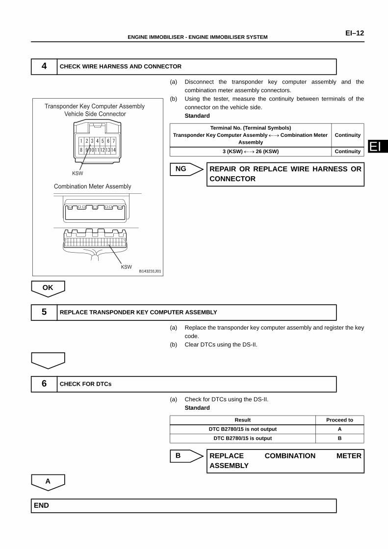
(a) Disconnect the transponder key computer assembly and thecombination meter assembly connectors.
(b) Using the tester, measure the continuity between terminals of theconnector on the vehicle side.Standard
NG
OK
(a) Replace the transponder key computer assembly and register the keycode.
(b) Clear DTCs using the DS-II.
(a) Check for DTCs using the DS-II.Standard
B
A
4 CHECK WIRE HARNESS AND CONNECTOR
Transponder Key Computer Assembly
Vehicle Side Connector
Combination Meter Assembly
KSW
KSWB143231J01
Terminal No. (Terminal Symbols)Transponder Key Computer Assembly ←→ Combination Meter
AssemblyContinuity
3 (KSW) ←→ 26 (KSW) Continuity
REPAIR OR REPLACE WIRE HARNESS ORCONNECTOR
5 REPLACE TRANSPONDER KEY COMPUTER ASSEMBLY
6 CHECK FOR DTCs
Result Proceed to
DTC B2780/15 is not output A
DTC B2780/15 is output B
REPLACE COMBINATION METERASSEMBLY
END
EI–13 ENGINE IMMOBILISER - ENGINE IMMOBILISER SYSTEM
EI
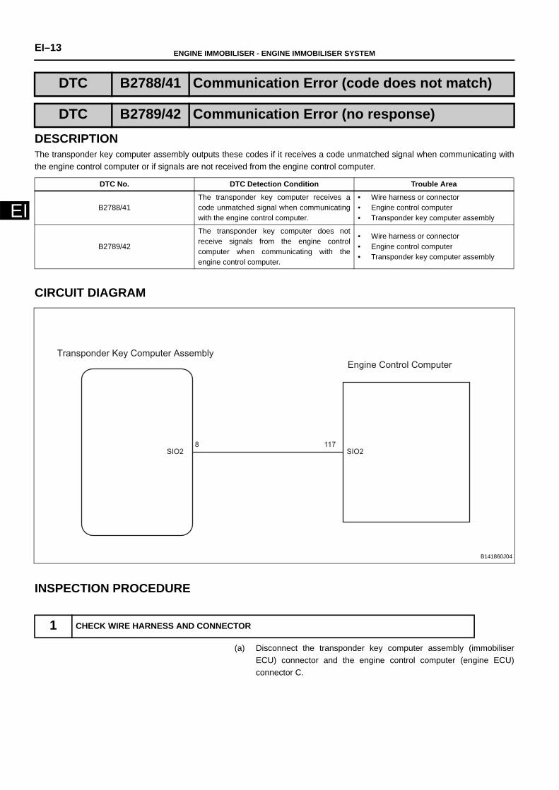
DESCRIPTIONThe transponder key computer assembly outputs these codes if it receives a code unmatched signal when communicating withthe engine control computer or if signals are not received from the engine control computer.
CIRCUIT DIAGRAM
INSPECTION PROCEDURE
(a) Disconnect the transponder key computer assembly (immobiliserECU) connector and the engine control computer (engine ECU)connector C.
DTC B2788/41 Communication Error (code does not match)
DTC B2789/42 Communication Error (no response)
DTC No. DTC Detection Condition Trouble Area
B2788/41The transponder key computer receives acode unmatched signal when communicatingwith the engine control computer.
• Wire harness or connector• Engine control computer• Transponder key computer assembly
B2789/42
The transponder key computer does notreceive signals from the engine controlcomputer when communicating with theengine control computer.
• Wire harness or connector• Engine control computer• Transponder key computer assembly
1 CHECK WIRE HARNESS AND CONNECTOR
Transponder Key Computer Assembly
Engine Control Computer
SIO2 SIO28 117
B141860J04

ENGINE IMMOBILISER - ENGINE IMMOBILISER SYSTEM EI–14
EI
(b) Using the tester, measure the continuity between terminals of theconnector on the vehicle wire harness side.Standard
NG
OK
(a) Replace the transponder key computer assembly and register the keycode.
(b) Clear DTCs using the DS-II.
(a) Check for DTCs using the DS-II.Standard
B
A
Transponder Key Computer Assembly
Vehicle Side Connector
Connector C
Engine Control Computer
SIO2
SIO2
B143232J01
Terminal No. (Terminal Symbols)Immobilizer ECU ←→ Engine ECU Continuity
8 (SIO2) ←→ 117 (SIO2) Continuity
REPAIR OR REPLACE WIRE HARNESS ORCONNECTOR
2 REPLACE TRANSPONDER KEY COMPUTER ASSEMBLY
3 CHECK FOR DTCs
Result Proceed to
DTCs B2788/41 and B2789/42 are not output A
DTCs B2788/41 and B2789/42 are output B
REPLACE ENGINE CONTROL COMPUTER
END
EI–15 ENGINE IMMOBILISER - ENGINE IMMOBILISER SYSTEM
EI
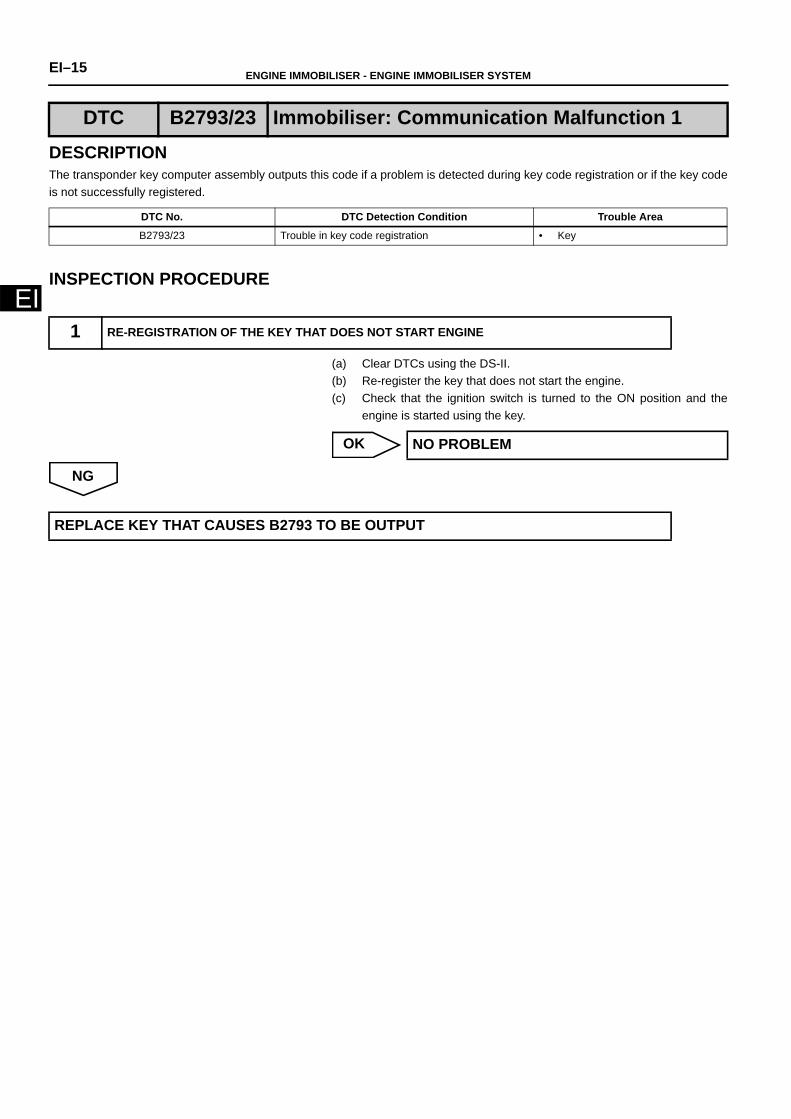
DESCRIPTIONThe transponder key computer assembly outputs this code if a problem is detected during key code registration or if the key codeis not successfully registered.
INSPECTION PROCEDURE
(a) Clear DTCs using the DS-II.(b) Re-register the key that does not start the engine.(c) Check that the ignition switch is turned to the ON position and the
engine is started using the key.
OK
NG
DTC B2793/23 Immobiliser: Communication Malfunction 1
DTC No. DTC Detection Condition Trouble Area
B2793/23 Trouble in key code registration • Key
1 RE-REGISTRATION OF THE KEY THAT DOES NOT START ENGINE
NO PROBLEM
REPLACE KEY THAT CAUSES B2793 TO BE OUTPUT

ENGINE IMMOBILISER - ENGINE IMMOBILISER SYSTEM EI–16
EI
DESCRIPTIONThe transponder key computer assembly outputs these codes if a malfunction is detected in communication between thetransponder key computer assembly and the key.
INSPECTION PROCEDURE
(a) Check if the ignition switch is turned to the ON position and theengine is started using another key. Standard:
The ignition switch is turned to the ON position and the engineis started.
OK
NG
DTC B2794/22 Immobiliser: Communication Malfunction 2
DTC No. DTC Detection Condition Trouble Area
B2794/22 Code key does not match• Key• Transponder key computer assembly
1 CHECK OPERATION WITH ANOTHER KEY
REPLACE KEY THAT DOES NOT STARTENGINE
REPLACE TRANSPONDER KEY COMPUTER ASSEMBLY
EI–17 ENGINE IMMOBILISER - ENGINE IMMOBILISER SYSTEM
EI
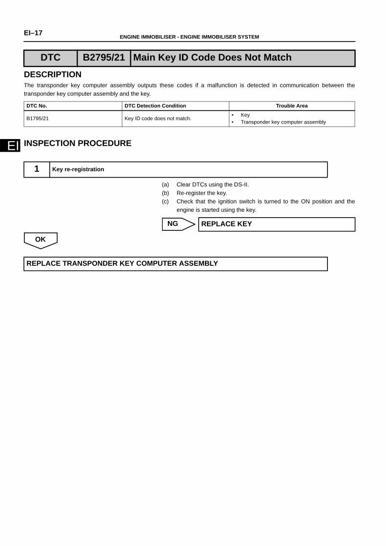
DESCRIPTIONThe transponder key computer assembly outputs these codes if a malfunction is detected in communication between thetransponder key computer assembly and the key.
INSPECTION PROCEDURE
(a) Clear DTCs using the DS-II.(b) Re-register the key.(c) Check that the ignition switch is turned to the ON position and the
engine is started using the key.
NG
OK
DTC B2795/21 Main Key ID Code Does Not Match
DTC No. DTC Detection Condition Trouble Area
B1795/21 Key ID code does not match.• Key• Transponder key computer assembly
1 Key re-registration
REPLACE KEY
REPLACE TRANSPONDER KEY COMPUTER ASSEMBLY

ENGINE IMMOBILISER - ENGINE IMMOBILISER SYSTEM EI–18
EI
DESCRIPTIONThose codes will be output through the transponder key computer assembly if a malfunction occurs due to a defect in the key orthe immobiliser in communication.
CIRCUIT DIAGRAM
DTC B2796/12 Main Key or Coil Malfunction
DTC B2797/24 Immobiliser: Communication Malfunction 4
DTC B2798/25 Immobiliser: Communication Malfunction 5
DTC No. DTC Detection Condition Trouble Area
B2796/12 ID code is not sent back
• Wire harness or connector• Key• Transponder key computer assembly• Steering column upper with switch
bracket assembly (immobiliser coil)
B2797/24 Transponder communication trouble
• Wire harness or connector• Key• Transponder key computer assembly• Steering column upper with switch
bracket assembly (immobiliser coil)
B2798/25Complete data is not received within aspecified time
• Wire harness or connector• Key• Transponder key computer assembly• Steering column upper with switch
bracket assembly (immobiliser coil)
Transponder Key Computer Assembly Steering Column Upper With Switch Bracket Assembly
(Immobiliser Coil)
COL+ COL+
COL- COL-
6
13
1
2
B141956J02
EI–19 ENGINE IMMOBILISER - ENGINE IMMOBILISER SYSTEM
EI
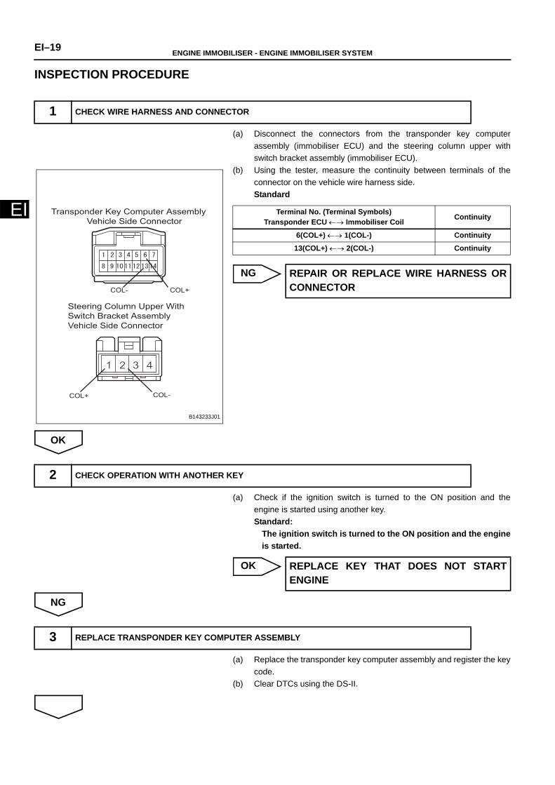
INSPECTION PROCEDURE
(a) Disconnect the connectors from the transponder key computerassembly (immobiliser ECU) and the steering column upper withswitch bracket assembly (immobiliser ECU).
(b) Using the tester, measure the continuity between terminals of theconnector on the vehicle wire harness side.Standard
NG
OK
(a) Check if the ignition switch is turned to the ON position and theengine is started using another key. Standard:
The ignition switch is turned to the ON position and the engineis started.
OK
NG
(a) Replace the transponder key computer assembly and register the keycode.
(b) Clear DTCs using the DS-II.
1 CHECK WIRE HARNESS AND CONNECTOR
Steering Column Upper With
Switch Bracket Assembly
Vehicle Side Connector
Transponder Key Computer Assembly
Vehicle Side Connector
COL- COL+
COL+ COL-
B143233J01
Terminal No. (Terminal Symbols)Transponder ECU ←→ Immobiliser Coil Continuity
6(COL+) ←→ 1(COL-) Continuity
13(COL+) ←→ 2(COL-) Continuity
REPAIR OR REPLACE WIRE HARNESS ORCONNECTOR
2 CHECK OPERATION WITH ANOTHER KEY
REPLACE KEY THAT DOES NOT STARTENGINE
3 REPLACE TRANSPONDER KEY COMPUTER ASSEMBLY
ENGINE IMMOBILISER - ENGINE IMMOBILISER SYSTEM EI–20
EI
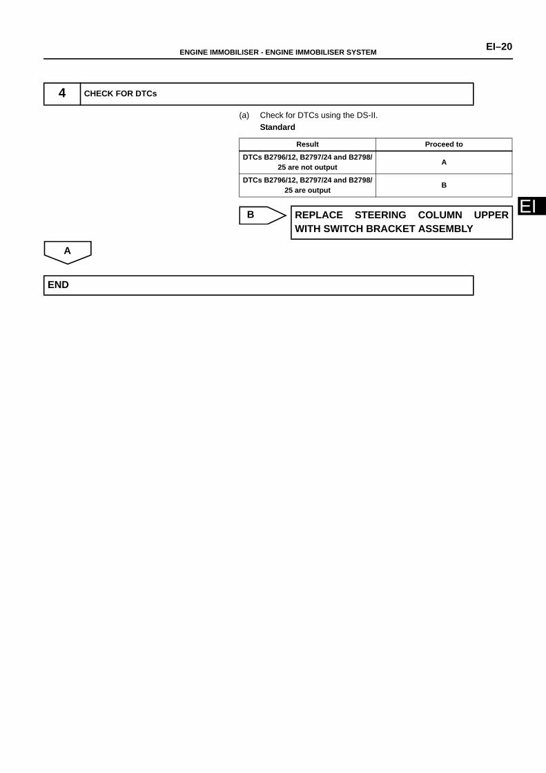
(a) Check for DTCs using the DS-II.Standard
B
A
4 CHECK FOR DTCs
Result Proceed to
DTCs B2796/12, B2797/24 and B2798/25 are not output A
DTCs B2796/12, B2797/24 and B2798/25 are output B
REPLACE STEERING COLUMN UPPERWITH SWITCH BRACKET ASSEMBLY
END
EI–21 ENGINE IMMOBILISER - ENGINE IMMOBILISER SYSTEM
EI
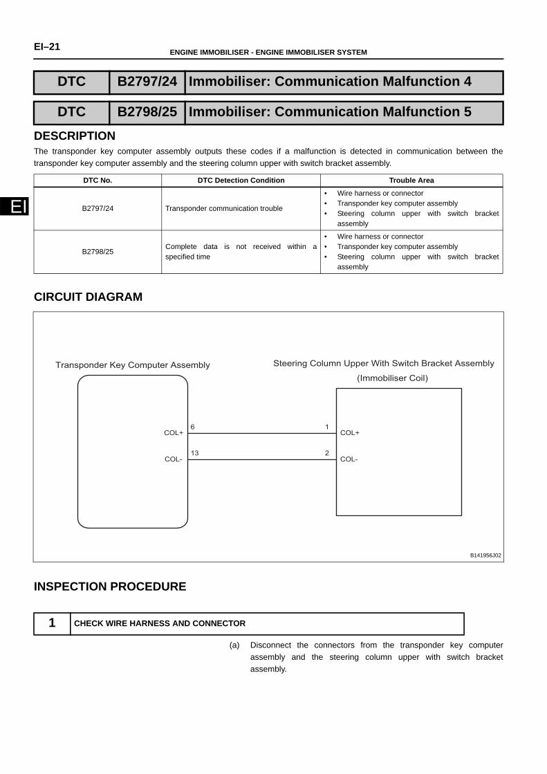
DESCRIPTIONThe transponder key computer assembly outputs these codes if a malfunction is detected in communication between thetransponder key computer assembly and the steering column upper with switch bracket assembly.
CIRCUIT DIAGRAM
INSPECTION PROCEDURE
(a) Disconnect the connectors from the transponder key computerassembly and the steering column upper with switch bracketassembly.
DTC B2797/24 Immobiliser: Communication Malfunction 4
DTC B2798/25 Immobiliser: Communication Malfunction 5
DTC No. DTC Detection Condition Trouble Area
B2797/24 Transponder communication trouble
• Wire harness or connector• Transponder key computer assembly• Steering column upper with switch bracket
assembly
B2798/25Complete data is not received within aspecified time
• Wire harness or connector• Transponder key computer assembly• Steering column upper with switch bracket
assembly
1 CHECK WIRE HARNESS AND CONNECTOR
Transponder Key Computer Assembly Steering Column Upper With Switch Bracket Assembly
(Immobiliser Coil)
COL+ COL+
COL- COL-
6
13
1
2
B141956J02

ENGINE IMMOBILISER - ENGINE IMMOBILISER SYSTEM EI–22
EI
(b) Using the tester, measure the continuity between terminals of theconnector on the vehicle wire harness side.Standard
NG
OK
(a) Replace the transponder key computer assembly and register the keycode.
(b) Clear DTCs using the DS-II.
(a) Check for DTCs using the DS-II.Standard
B
A
Steering Column Upper With
Switch Bracket Assembly
Vehicle Side Connector
Transponder Key Computer Assembly
Vehicle Side Connector
COL- COL+
COL+ COL-
B143233J01
Terminal No. (Terminal Symbols)Immobiliser ECU ←→ Steering column upper with switch
bracket assemblyContinuity
6(COL+) ←→ 1(COL-) Continuity
13(COL+) ←→ 2(COL-) Continuity
REPAIR OR REPLACE WIRE HARNESS ORCONNECTOR
2 REPLACE TRANSPONDER KEY COMPUTER ASSEMBLY
3 CHECK FOR DTCs
Result Proceed to
DTCs B2797/24 and B2798/25 are not output A
DTCs B2797/24 and B2798/25 are output B
REPLACE STEERING COLUMN UPPERWITH SWITCH BRACKET ASSEMBLY
END
TO INDEX TO NEXT SECTION