Embed Size (px)
Citation preview
ENGINE IMMOBILISER – ENGINE IMMOBILISER SYSTEM EI–1
I
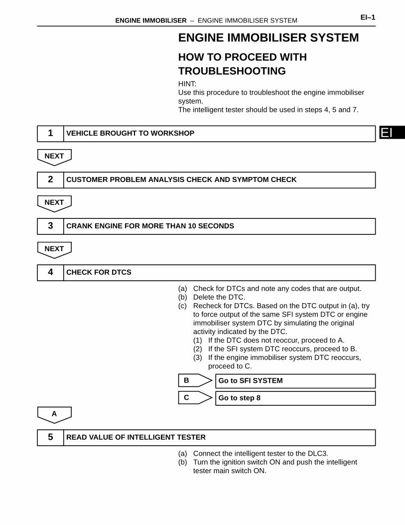
EENGINE IMMOBILISER SYSTEMHOW TO PROCEED WITH TROUBLESHOOTINGHINT:Use this procedure to troubleshoot the engine immobiliser system.The intelligent tester should be used in steps 4, 5 and 7.
NEXT
NEXT
NEXT
(a) Check for DTCs and note any codes that are output.(b) Delete the DTC.(c) Recheck for DTCs. Based on the DTC output in (a), try
to force output of the same SFI system DTC or engine immobiliser system DTC by simulating the original activity indicated by the DTC.(1) If the DTC does not reoccur, proceed to A.(2) If the SFI system DTC reoccurs, proceed to B.(3) If the engine immobiliser system DTC reoccurs,
proceed to C.
B
C
A
(a) Connect the intelligent tester to the DLC3.(b) Turn the ignition switch ON and push the intelligent
tester main switch ON.
1 VEHICLE BROUGHT TO WORKSHOP
2 CUSTOMER PROBLEM ANALYSIS CHECK AND SYMPTOM CHECK
3 CRANK ENGINE FOR MORE THAN 10 SECONDS
4 CHECK FOR DTCS
Go to SFI SYSTEM
Go to step 8
5 READ VALUE OF INTELLIGENT TESTER
EI–2 ENGINE IMMOBILISER – ENGINE IMMOBILISER SYSTEM
EI
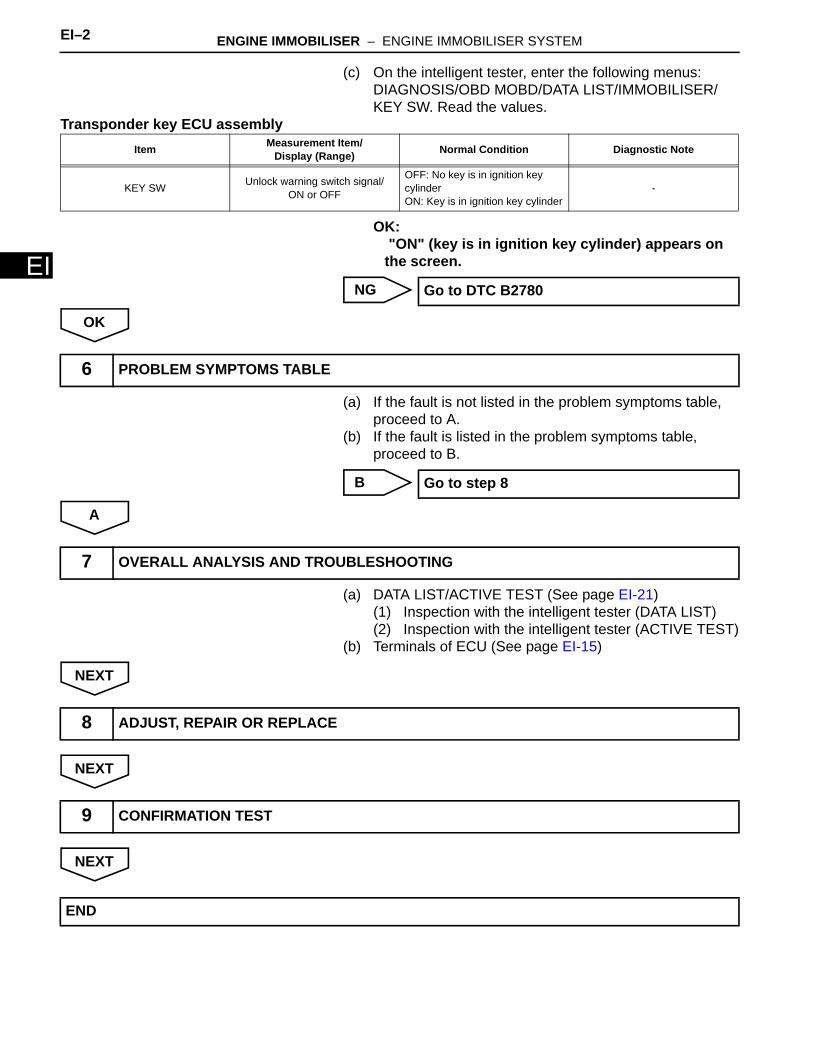
(c) On the intelligent tester, enter the following menus: DIAGNOSIS/OBD MOBD/DATA LIST/IMMOBILISER/KEY SW. Read the values.
Transponder key ECU assembly
OK: "ON" (key is in ignition key cylinder) appears on the screen.
NG
OK
(a) If the fault is not listed in the problem symptoms table, proceed to A.
(b) If the fault is listed in the problem symptoms table, proceed to B.
B
A
(a) DATA LIST/ACTIVE TEST (See page EI-21) (1) Inspection with the intelligent tester (DATA LIST)(2) Inspection with the intelligent tester (ACTIVE TEST)
(b) Terminals of ECU (See page EI-15)
NEXT
NEXT
NEXT
Item Measurement Item/Display (Range) Normal Condition Diagnostic Note
KEY SW Unlock warning switch signal/ON or OFF
OFF: No key is in ignition key cylinderON: Key is in ignition key cylinder
-
Go to DTC B2780
6 PROBLEM SYMPTOMS TABLE
Go to step 8
7 OVERALL ANALYSIS AND TROUBLESHOOTING
8 ADJUST, REPAIR OR REPLACE
9 CONFIRMATION TEST
END
ENGINE IMMOBILISER – ENGINE IMMOBILISER SYSTEM EI–3
I
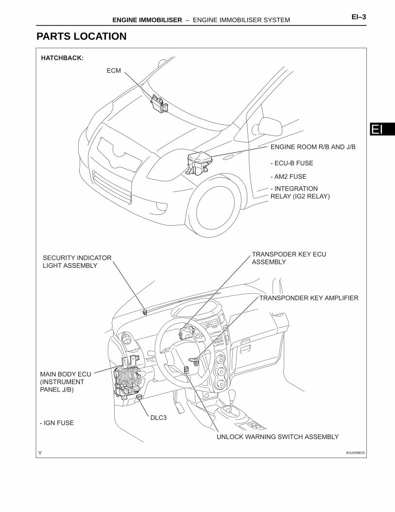
EPARTS LOCATION
ENGINE ROOM R/B AND J/B
ECM
SECURITY INDICATOR
LIGHT ASSEMBLY
MAIN BODY ECU
(INSTRUMENT
PANEL J/B)
TRANSPODER KEY ECU
ASSEMBLY
TRANSPONDER KEY AMPLIFIER
DLC3
- ECU-B FUSE
- AM2 FUSE
HATCHBACK:
- IGN FUSE
- INTEGRATION
RELAY (IG2 RELAY)
UNLOCK WARNING SWITCH ASSEMBLY
B116296E03
EI–4 ENGINE IMMOBILISER – ENGINE IMMOBILISER SYSTEM
EI
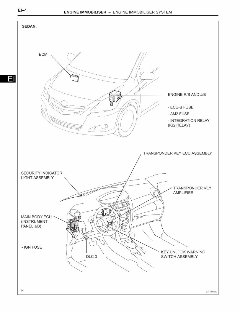
SEDAN:
ECM
MAIN BODY ECU
(INSTRUMENT
PANEL J/B)
- INTEGRATION RELAY
(IG2 RELAY)
- AM2 FUSE
- ECU-B FUSE
ENGINE R/B AND J/B
SECURITY INDICATOR
LIGHT ASSEMBLY
TRANSPONDER KEY
AMPLIFIER
TRANSPONDER KEY ECU ASSEMBLY
DLC 3
KEY UNLOCK WARNING
SWITCH ASSEMBLY
- IGN FUSE
B143387E01
ENGINE IMMOBILISER – ENGINE IMMOBILISER SYSTEM EI–5
I
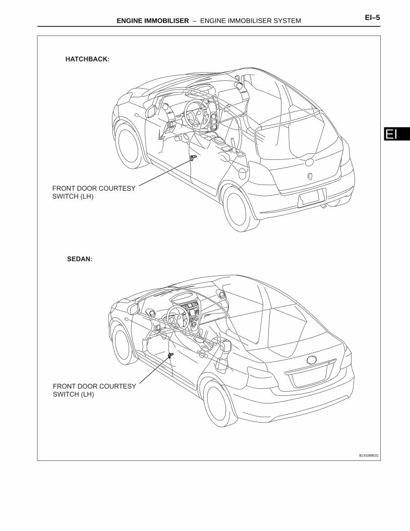
EFRONT DOOR COURTESY
SWITCH (LH)
FRONT DOOR COURTESY
SWITCH (LH)
HATCHBACK:
SEDAN:
B143388E01
EI–6 ENGINE IMMOBILISER – ENGINE IMMOBILISER SYSTEM
EI
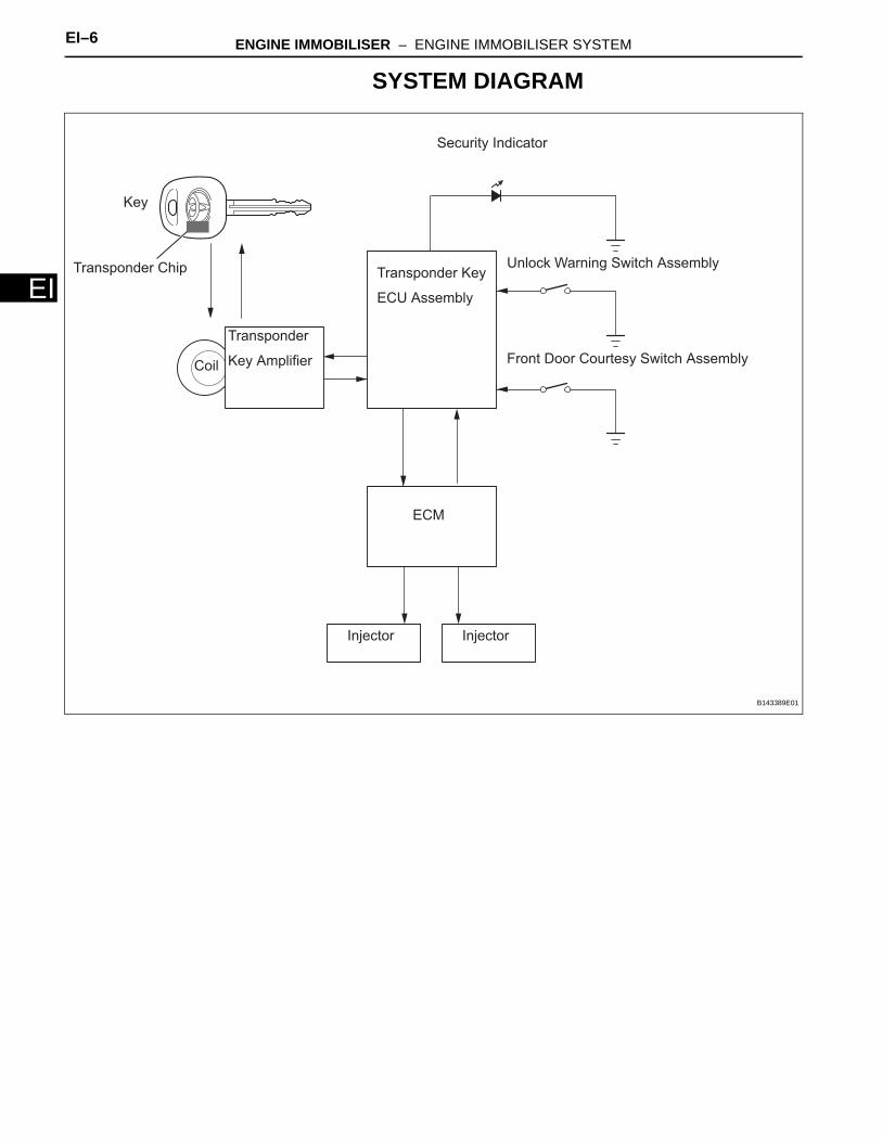
SYSTEM DIAGRAM
Key
Transponder Chip
Security Indicator
Front Door Courtesy Switch Assembly
Unlock Warning Switch Assembly
Transponder
Key Amplifier
Transponder Key
ECU Assembly
ECM
Injector
Coil
Injector
B143389E01
ENGINE IMMOBILISER – ENGINE IMMOBILISER SYSTEM EI–7
I
ESYSTEM DESCRIPTION1. ENGINE IMMOBILISER SYSTEM DESCRIPTION
The engine immobiliser system is designed to prevent the vehicle from being stolen. This system uses a transponder key ECU that stores the key codes of authorized ignition keys. If an attempt is made to start the engine using an unauthorized key, the ECU sends a signal to the ECM to prohibit fuel delivery and ignition, effectively disabling the engine.
2. FUNCTIONS OF MAIN COMPONENTS
3. SYSTEM FUNCTION• When the transponder key ECU assembly detects
that the unlock warning switch is ON, the ECU provides current to the transponder key coil and produces a faint electric wave. A transponder chip in the key grip receives the faint electric wave. Upon receiving the faint electric wave, the transponder chip outputs a key ID code signal. The transponder key coil receives this signal, the transponder key amplifier amplifies it, and then the signal is transmitted to the ECU. The ECU compares the key's ID code with the vehicle's ID code, which was previously registered in the ECU and then communicates the results to the ECM using the SFI communication.
• After the identification results show that the key's ID code matches the vehicle's ID code and the ECU has confirmed that they match: 1) the immobiliser system is canceled and the engine starting controls (fuel injection control and ignition control) enter standby mode; and 2) the ECU transmits a security indicator signal that communicates "indicator OFF" to the transponder key ECU. Then, the transponder key ECU turns OFF the security indicator light.
Component Outline
Transponder key coil/amplifierWhen key is inserted in ignition key cylinder, key coil receives key
code. Then amplifier amplifies ID code and outputs it to transponder key ECU assembly.
Unlock warning switch assembly Detects if key is in ignition key cylinder and outputs results to transponder key ECU assembly.
ECMThrough SFI communication, ECM receives ID verification results
from transponder key ECU assembly. ECM also verifies ECUs. Then judges whether or not to enter immobiliser engine mode.
Security indicator light Depending on operation of transponder key ECU, interior security indicator light comes on or starts blinking.
EI–8 ENGINE IMMOBILISER – ENGINE IMMOBILISER SYSTEM
EI
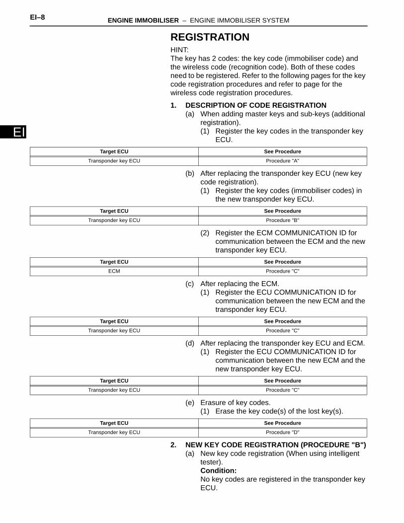
REGISTRATIONHINT:The key has 2 codes: the key code (immobiliser code) and the wireless code (recognition code). Both of these codes need to be registered. Refer to the following pages for the key code registration procedures and refer to page for the wireless code registration procedures.
1. DESCRIPTION OF CODE REGISTRATION(a) When adding master keys and sub-keys (additional
registration). (1) Register the key codes in the transponder key
ECU.
(b) After replacing the transponder key ECU (new key code registration).(1) Register the key codes (immobiliser codes) in
the new transponder key ECU.
(2) Register the ECM COMMUNICATION ID for communication between the ECM and the new transponder key ECU.
(c) After replacing the ECM.(1) Register the ECU COMMUNICATION ID for
communication between the new ECM and the transponder key ECU.
(d) After replacing the transponder key ECU and ECM.(1) Register the ECU COMMUNICATION ID for
communication between the new ECM and the new transponder key ECU.
(e) Erasure of key codes.(1) Erase the key code(s) of the lost key(s).
2. NEW KEY CODE REGISTRATION (PROCEDURE "B")(a) New key code registration (When using intelligent
tester).Condition:No key codes are registered in the transponder key ECU.
Target ECU See Procedure
Transponder key ECU Procedure "A"
Target ECU See Procedure
Transponder key ECU Procedure "B"
Target ECU See Procedure
ECM Procedure "C"
Target ECU See Procedure
Transponder key ECU Procedure "C"
Target ECU See Procedure
Transponder key ECU Procedure "C"
Target ECU See Procedure
Transponder key ECU Procedure "D"
ENGINE IMMOBILISER – ENGINE IMMOBILISER SYSTEM EI–9
I
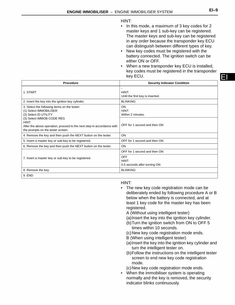
EHINT:• In this mode, a maximum of 3 key codes for 2
master keys and 1 sub-key can be registered. The master keys and sub-key can be registered in any order because the transponder key ECU can distinguish between different types of key.
• New key codes must be registered with the battery connected. The ignition switch can be either ON or OFF.
• When a new transponder key ECU is installed, key codes must be registered in the transponder key ECU.
HINT:• The new key code registration mode can be
deliberately ended by following procedure A or B below when the battery is connected, and at least 1 key code for the master key has been registered.A (Without using intelligent tester)(a)Insert the key into the ignition key cylinder.(b)Turn the ignition switch from ON to OFF 5
times within 10 seconds.(c)New key code registration mode ends.B (When using intelligent tester)(a)Insert the key into the ignition key cylinder and
turn the intelligent tester on.(b)Follow the instructions on the intelligent tester
screen to end new key code registration mode.
(c)New key code registration mode ends.• When the immobiliser system is operating
normally and the key is removed, the security indicator blinks continuously.
Procedure Security Indicator Condition
1. START-HINT:Until the first key is inserted.
2. Insert the key into the ignition key cylinder. BLINKING
3. Select the following items on the tester:(1) Select IMMOBILISER(2) Select ID UTILITY(3) Select IMMOB CODE REGHINT:After the above operation, proceed to the next step in accordance with the prompts on the tester screen.
ONHINT:Within 2 minutes.
OFF for 1 second and then ON
4. Remove the key and then push the NEXT button on the tester. ON
5. Insert a master key or sub-key to be registered. OFF for 1 second and then ON
6. Remove the key and then push the NEXT button on the tester. ON
7. Insert a master key or sub-key to be registered.
OFF for 1 second and then ON
OFFHINT:0.5 seconds after turning ON
8. Remove the key. BLINKING
9. END
EI–10 ENGINE IMMOBILISER – ENGINE IMMOBILISER SYSTEM
EI
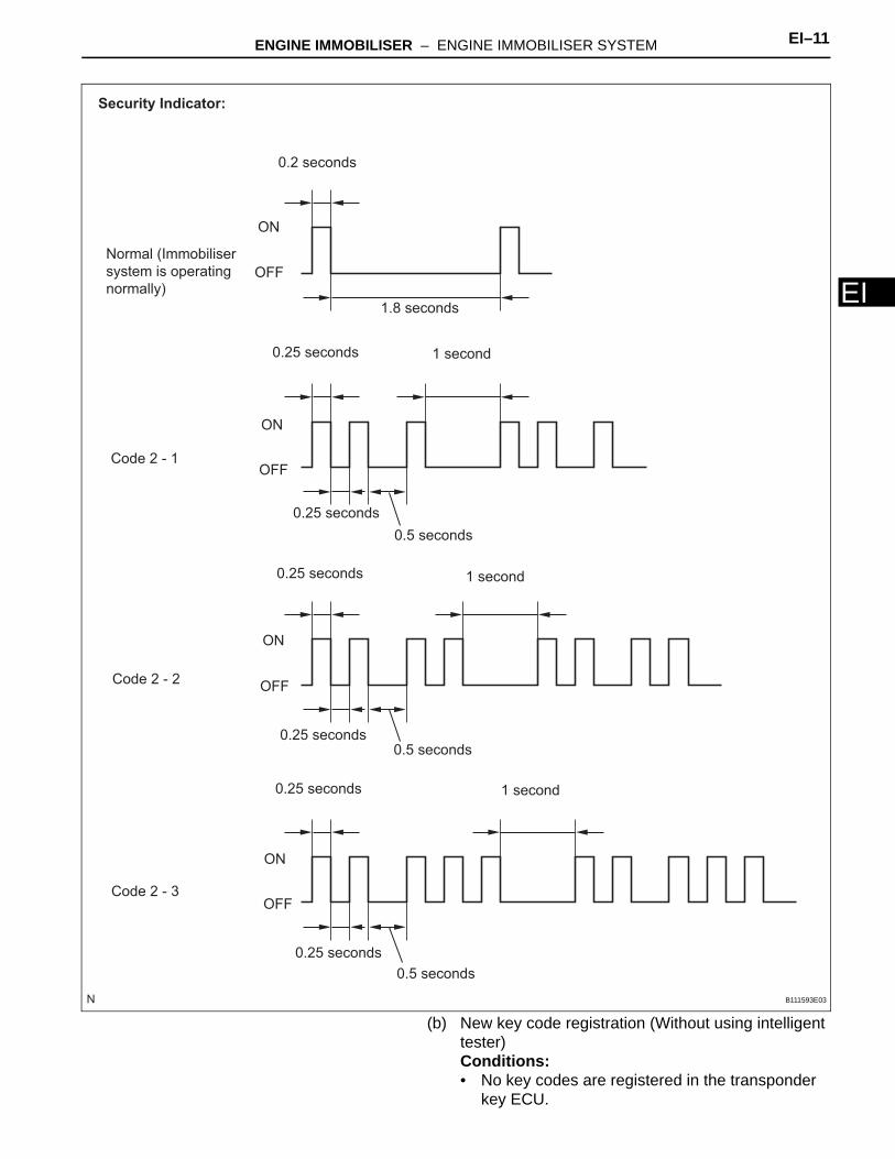
• If the new key code registration fails, code 2-1 is output by the security indicator. Trying to re-register an already registered key causes code 2-2 to be output when the key is inserted. If the number of registered key codes exceeds the limit, code 2-3 is output by the security indicator. The output details are shown below.
ENGINE IMMOBILISER – ENGINE IMMOBILISER SYSTEM EI–11
I
E(b) New key code registration (Without using intelligent tester)Conditions:• No key codes are registered in the transponder
key ECU.
Normal (Immobiliser
system is operating
normally)
Code 2 - 1
Code 2 - 2
Code 2 - 3
0.2 seconds
1.8 seconds
ON
OFF
ON
OFF
ON
OFF
0.25 seconds
0.25 seconds
0.5 seconds
1 second
ON
OFF
0.25 seconds 1 second
0.25 seconds0.5 seconds
0.25 seconds
0.25 seconds
1 second
0.5 seconds
Security Indicator:
B111593E03
EI–12 ENGINE IMMOBILISER – ENGINE IMMOBILISER SYSTEM
EI
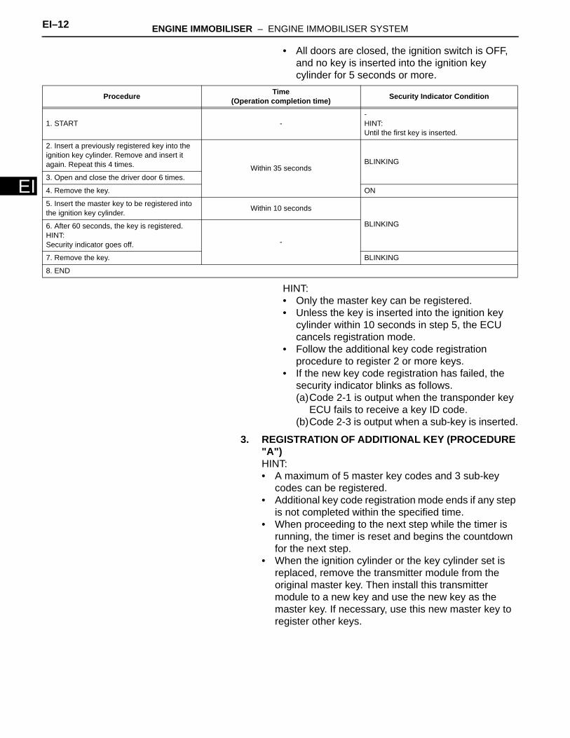
• All doors are closed, the ignition switch is OFF, and no key is inserted into the ignition key cylinder for 5 seconds or more.
HINT:• Only the master key can be registered.• Unless the key is inserted into the ignition key
cylinder within 10 seconds in step 5, the ECU cancels registration mode.
• Follow the additional key code registration procedure to register 2 or more keys.
• If the new key code registration has failed, the security indicator blinks as follows.(a)Code 2-1 is output when the transponder key
ECU fails to receive a key ID code.(b)Code 2-3 is output when a sub-key is inserted.
3. REGISTRATION OF ADDITIONAL KEY (PROCEDURE "A")HINT:• A maximum of 5 master key codes and 3 sub-key
codes can be registered.• Additional key code registration mode ends if any step
is not completed within the specified time.• When proceeding to the next step while the timer is
running, the timer is reset and begins the countdown for the next step.
• When the ignition cylinder or the key cylinder set is replaced, remove the transmitter module from the original master key. Then install this transmitter module to a new key and use the new key as the master key. If necessary, use this new master key to register other keys.
Procedure Time(Operation completion time) Security Indicator Condition
1. START --HINT:Until the first key is inserted.
2. Insert a previously registered key into the ignition key cylinder. Remove and insert it again. Repeat this 4 times. Within 35 seconds
BLINKING
3. Open and close the driver door 6 times.
4. Remove the key. ON
5. Insert the master key to be registered into the ignition key cylinder. Within 10 seconds
BLINKING6. After 60 seconds, the key is registered.HINT:Security indicator goes off. -
7. Remove the key. BLINKING
8. END
ENGINE IMMOBILISER – ENGINE IMMOBILISER SYSTEM EI–13
I
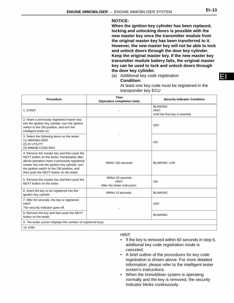
ENOTICE:When the ignition key cylinder has been replaced, locking and unlocking doors is possible with the new master key once the transmitter module from the original master key has been transferred to it. However, the new master key will not be able to lock and unlock doors through the door key cylinder. Keep the original master key. If the new master key transmitter module battery fails, the original master key can be used to lock and unlock doors through the door key cylinder.(a) Additional key code registration
Condition:At least one key code must be registered in the transponder key ECU
HINT:• If the key is removed within 60 seconds in step 6,
additional key code registration mode is canceled.
• A brief outline of the procedures for key code registration is shown above. For more detailed information, please refer to the intelligent tester screen's instructions.
• When the immobiliser system is operating normally and the key is removed, the security indicator blinks continuously.
Procedure Time(Operation completion time) Security Indicator Condition
1. START -BLINKINGHINT:Until the first key is inserted.
2. Insert a previously registered master key into the ignition key cylinder, turn the ignition switch to the ON position, and turn the intelligent tester on.
-
OFF
3. Select the following items on the tester:(1) IMMOBILISER(2) ID UTILITY(3) IMMOB CODE REG
ON
4. Remove the master key and then push the NEXT button on the tester. Immediately after above operation insert a previously registered master key into the ignition key cylinder, turn the ignition switch to the ON position, and then push the NEXT button on the tester.
Within 120 seconds BLINKING→ON
5. Remove the master key and then push the NEXT button on the tester.
Within 20 secondsHINT:
After the tester instruction.ON
6. Insert the key to be registered into the ignition key cylinder. Within 10 seconds. BLINKING
7. After 60 seconds, the key is registered.HINT:The security indicator goes off. -
OFF
8. Remove the key and then push the NEXT button on the tester. BLINKING
9. The tester screen displays the number of registered keys.
10. END
EI–14 ENGINE IMMOBILISER – ENGINE IMMOBILISER SYSTEM
EI
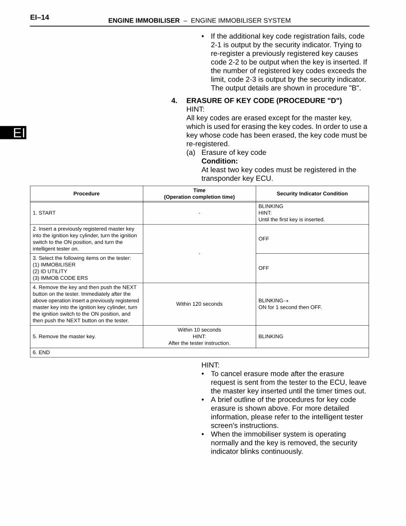
• If the additional key code registration fails, code 2-1 is output by the security indicator. Trying to re-register a previously registered key causes code 2-2 to be output when the key is inserted. If the number of registered key codes exceeds the limit, code 2-3 is output by the security indicator. The output details are shown in procedure "B".
4. ERASURE OF KEY CODE (PROCEDURE "D")HINT:All key codes are erased except for the master key, which is used for erasing the key codes. In order to use a key whose code has been erased, the key code must be re-registered.(a) Erasure of key code
Condition:At least two key codes must be registered in the transponder key ECU.
HINT:• To cancel erasure mode after the erasure
request is sent from the tester to the ECU, leave the master key inserted until the timer times out.
• A brief outline of the procedures for key code erasure is shown above. For more detailed information, please refer to the intelligent tester screen's instructions.
• When the immobiliser system is operating normally and the key is removed, the security indicator blinks continuously.
Procedure Time(Operation completion time) Security Indicator Condition
1. START -BLINKINGHINT:Until the first key is inserted.
2. Insert a previously registered master key into the ignition key cylinder, turn the ignition switch to the ON position, and turn the intelligent tester on.
-
OFF
3. Select the following items on the tester:(1) IMMOBILISER(2) ID UTILITY(3) IMMOB CODE ERS
OFF
4. Remove the key and then push the NEXT button on the tester. Immediately after the above operation insert a previously registered master key into the ignition key cylinder, turn the ignition switch to the ON position, and then push the NEXT button on the tester.
Within 120 seconds BLINKING→ON for 1 second then OFF.
5. Remove the master key.Within 10 seconds
HINT:After the tester instruction.
BLINKING
6. END
ENGINE IMMOBILISER – ENGINE IMMOBILISER SYSTEM EI–15
I
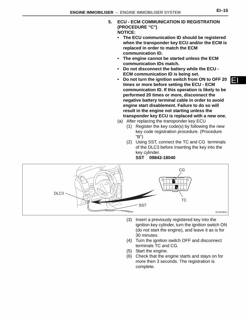
E5. ECU - ECM COMMUNICATION ID REGISTRATION (PROCEDURE "C")NOTICE:• The ECU communication ID should be registered
when the transponder key ECU and/or the ECM is replaced in order to match the ECM communication ID.
• The engine cannot be started unless the ECM communication IDs match.
• Do not disconnect the battery while the ECU - ECM communication ID is being set.
• Do not turn the ignition switch from ON to OFF 20 times or more before setting the ECU - ECM communication ID. If this operation is likely to be performed 20 times or more, disconnect the negative battery terminal cable in order to avoid engine start disablement. Failure to do so will result in the engine not starting unless the transponder key ECU is replaced with a new one.
(a) After replacing the transponder key ECU(1) Register the key code(s) by following the new
key code registration procedure. (Procedure "B")
(2) Using SST, connect the TC and CG terminals of the DLC3 before inserting the key into the key cylinder.SST 09843-18040
(3) Insert a previously registered key into the ignition key cylinder, turn the ignition switch ON (do not start the engine), and leave it as is for 30 minutes.
(4) Turn the ignition switch OFF and disconnect terminals TC and CG.
(5) Start the engine.(6) Check that the engine starts and stays on for
more then 3 seconds. The registration is complete.
DLC3
SST
CG
TC
B128293E01
EI–16 ENGINE IMMOBILISER – ENGINE IMMOBILISER SYSTEM
EI
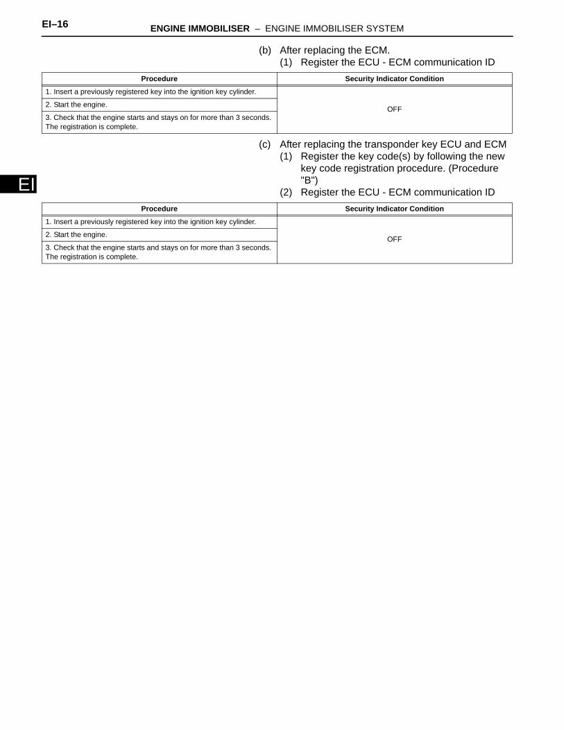
(b) After replacing the ECM.(1) Register the ECU - ECM communication ID
(c) After replacing the transponder key ECU and ECM(1) Register the key code(s) by following the new
key code registration procedure. (Procedure "B")
(2) Register the ECU - ECM communication ID
Procedure Security Indicator Condition
1. Insert a previously registered key into the ignition key cylinder.
OFF2. Start the engine.
3. Check that the engine starts and stays on for more than 3 seconds. The registration is complete.
Procedure Security Indicator Condition
1. Insert a previously registered key into the ignition key cylinder.
OFF2. Start the engine.
3. Check that the engine starts and stays on for more than 3 seconds. The registration is complete.
ENGINE IMMOBILISER – ENGINE IMMOBILISER SYSTEM EI–17
I
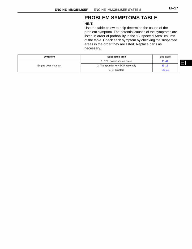
EPROBLEM SYMPTOMS TABLEHINT:Use the table below to help determine the cause of the problem symptom. The potential causes of the symptoms are listed in order of probability in the "Suspected Area" column of the table. Check each symptom by checking the suspected areas in the order they are listed. Replace parts as necessary.
Symptom Suspected area See page
Engine does not start
1. ECU power source circuit EI-44
2. Transponder key ECU assembly EI-15
3. SFI system ES-24
EI–18 ENGINE IMMOBILISER – ENGINE IMMOBILISER SYSTEM
EI
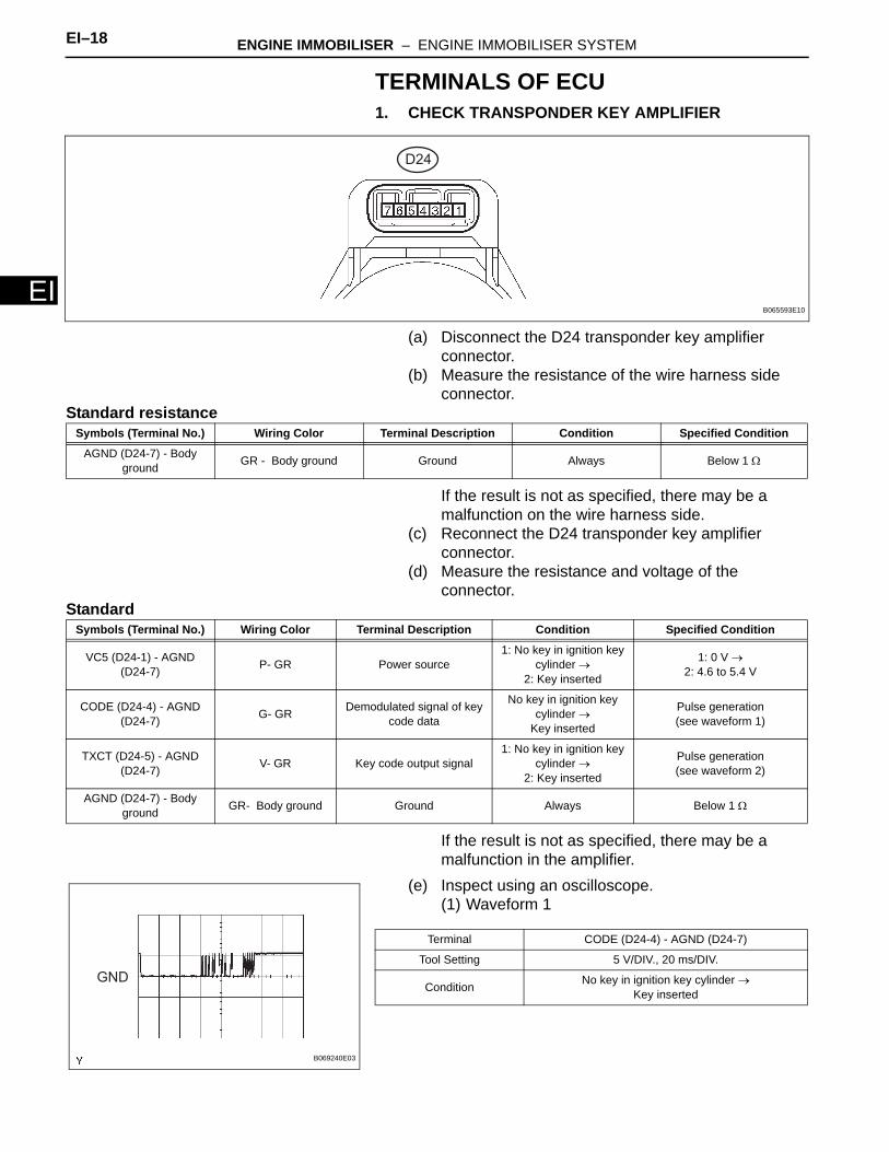
TERMINALS OF ECU1. CHECK TRANSPONDER KEY AMPLIFIER
(a) Disconnect the D24 transponder key amplifier connector.
(b) Measure the resistance of the wire harness side connector.
Standard resistance
If the result is not as specified, there may be a malfunction on the wire harness side.
(c) Reconnect the D24 transponder key amplifier connector.
(d) Measure the resistance and voltage of the connector.
Standard
If the result is not as specified, there may be a malfunction in the amplifier.
(e) Inspect using an oscilloscope.(1) Waveform 1
D24
B065593E10
Symbols (Terminal No.) Wiring Color Terminal Description Condition Specified Condition
AGND (D24-7) - Body ground GR - Body ground Ground Always Below 1 Ω
Symbols (Terminal No.) Wiring Color Terminal Description Condition Specified Condition
VC5 (D24-1) - AGND (D24-7) P- GR Power source
1: No key in ignition key cylinder →
2: Key inserted
1: 0 V →2: 4.6 to 5.4 V
CODE (D24-4) - AGND (D24-7) G- GR Demodulated signal of key
code data
No key in ignition key cylinder →
Key inserted
Pulse generation(see waveform 1)
TXCT (D24-5) - AGND (D24-7) V- GR Key code output signal
1: No key in ignition key cylinder →
2: Key inserted
Pulse generation(see waveform 2)
AGND (D24-7) - Body ground GR- Body ground Ground Always Below 1 Ω
GND
B069240E03
Terminal CODE (D24-4) - AGND (D24-7)
Tool Setting 5 V/DIV., 20 ms/DIV.
Condition No key in ignition key cylinder → Key inserted
ENGINE IMMOBILISER – ENGINE IMMOBILISER SYSTEM EI–19
I
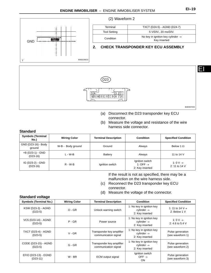
E(2) Waveform 2
2. CHECK TRANSPONDER KEY ECU ASSEMBLY
(a) Disconnect the D23 transponder key ECU connector.
(b) Measure the voltage and resistance of the wire harness side connector.
Standard
If the result is not as specified, there may be a malfunction on the wire harness side.
(c) Reconnect the D23 transponder key ECU connector.
(d) Measure the voltage of the connector.Standard voltage
GND
B069239E03
Terminal TXCT (D24-5) - AGND (D24-7)
Tool Setting 5 V/DIV., 20 ms/DIV.
Condition No key in ignition key cylinder →Key inserted
D23
B085907E05
Symbols (Terminal No.) Wiring Color Terminal Description Condition Specified Condition
GND (D23-16) - Body ground W-B - Body ground Ground Always Below 1 Ω
+B (D23-1) - GND (D23-16) L - W-B Battery Always 11 to 14 V
IG (D23-2) - GND (D23-16) R - W-B Ignition switch
Ignition switch1: OFF →
2: Key inserted
1: 0 V →2: 11 to 14 V
Symbols (Terminal No.) Wiring Color Terminal Description Condition Specified Condition
KSW (D23-3) - AGND (D23-5) O - GR Unlock warning switch
1: No key in ignition key cylinder →
2: Key inserted
1: 11 to 14 V→2: Below 1 V
VC5 (D23-14) - AGND (D23-5) P - GR Power source
1: No key in ignition key cylinder →
2: Key inserted
1: 0 V →2: 4.6 to 5.4 V
TXCT (D23-4) - AGND (D23-5) V - GR Transponder key amplifier
communication signal
1: No key in ignition key cylinder →
2: Key inserted
Pulse generation(see waveform 1)
CODE (D23-15) - AGND (D23-5) G - GR Transponder key amplifier
communication signal
1: No key in ignition key cylinder →
2: Key inserted
Pulse generation(see waveform 2)
EFIO (D23-13) - EGND (D23-11) W - BR ECM output signal
Ignition switchOFF →
ON
Pulse generation(see waveform 3)
EI–20 ENGINE IMMOBILISER – ENGINE IMMOBILISER SYSTEM
EI
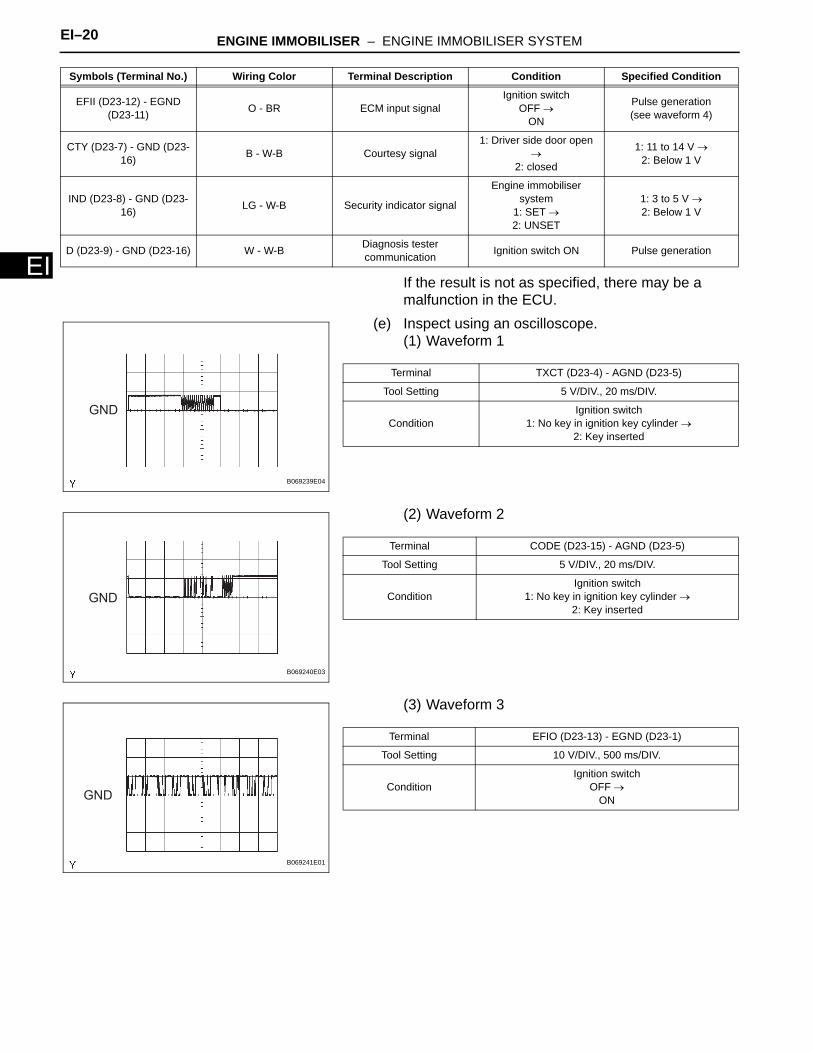
If the result is not as specified, there may be a malfunction in the ECU.(e) Inspect using an oscilloscope.(1) Waveform 1
(2) Waveform 2
(3) Waveform 3
EFII (D23-12) - EGND (D23-11) O - BR ECM input signal
Ignition switchOFF →
ON
Pulse generation(see waveform 4)
CTY (D23-7) - GND (D23-16) B - W-B Courtesy signal
1: Driver side door open →
2: closed
1: 11 to 14 V →2: Below 1 V
IND (D23-8) - GND (D23-16) LG - W-B Security indicator signal
Engine immobiliser system
1: SET →2: UNSET
1: 3 to 5 V →2: Below 1 V
D (D23-9) - GND (D23-16) W - W-B Diagnosis tester communication Ignition switch ON Pulse generation
Symbols (Terminal No.) Wiring Color Terminal Description Condition Specified Condition
GND
B069239E04
Terminal TXCT (D23-4) - AGND (D23-5)
Tool Setting 5 V/DIV., 20 ms/DIV.
ConditionIgnition switch
1: No key in ignition key cylinder →2: Key inserted
GND
B069240E03
Terminal CODE (D23-15) - AGND (D23-5)
Tool Setting 5 V/DIV., 20 ms/DIV.
ConditionIgnition switch
1: No key in ignition key cylinder →2: Key inserted
GND
B069241E01
Terminal EFIO (D23-13) - EGND (D23-1)
Tool Setting 10 V/DIV., 500 ms/DIV.
ConditionIgnition switch
OFF →ON
ENGINE IMMOBILISER – ENGINE IMMOBILISER SYSTEM EI–21
I
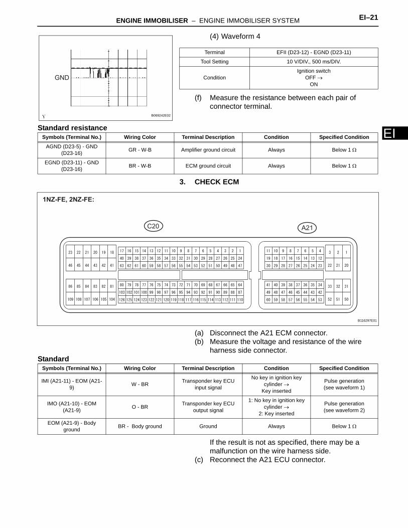
E(4) Waveform 4
(f) Measure the resistance between each pair of connector terminal.
Standard resistance
3. CHECK ECM
(a) Disconnect the A21 ECM connector.(b) Measure the voltage and resistance of the wire
harness side connector.Standard
If the result is not as specified, there may be a malfunction on the wire harness side.
(c) Reconnect the A21 ECU connector.
GND
B069242E02
Terminal EFII (D23-12) - EGND (D23-11)
Tool Setting 10 V/DIV., 500 ms/DIV.
ConditionIgnition switch
OFF →ON
Symbols (Terminal No.) Wiring Color Terminal Description Condition Specified Condition
AGND (D23-5) - GND (D23-16) GR - W-B Amplifier ground circuit Always Below 1 Ω
EGND (D23-11) - GND (D23-16) BR - W-B ECM ground circuit Always Below 1 Ω
A21
1NZ-FE, 2NZ-FE:
C20
B116297E01
Symbols (Terminal No.) Wiring Color Terminal Description Condition Specified Condition
IMI (A21-11) - EOM (A21-9) W - BR Transponder key ECU
input signal
No key in ignition key cylinder →
Key inserted
Pulse generation(see waveform 1)
IMO (A21-10) - EOM (A21-9) O - BR Transponder key ECU
output signal
1: No key in ignition key cylinder →
2: Key inserted
Pulse generation(see waveform 2)
EOM (A21-9) - Body ground BR - Body ground Ground Always Below 1 Ω
EI–22 ENGINE IMMOBILISER – ENGINE IMMOBILISER SYSTEM
EI
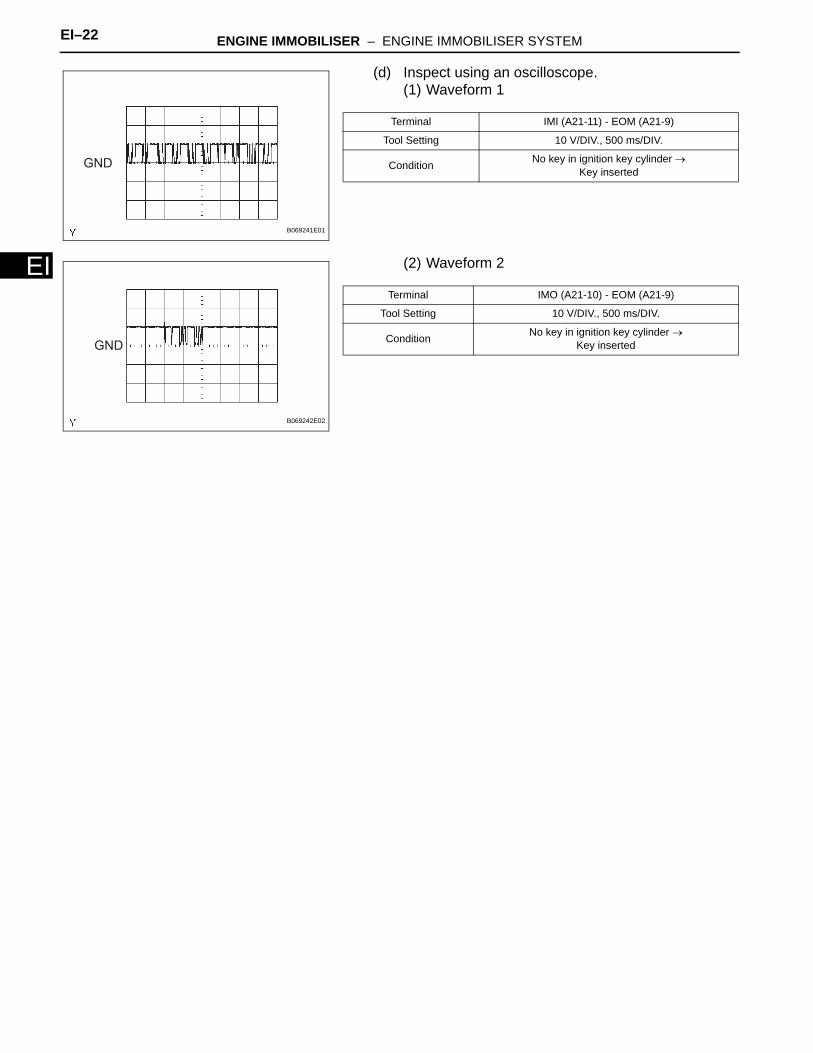
(d) Inspect using an oscilloscope.(1) Waveform 1
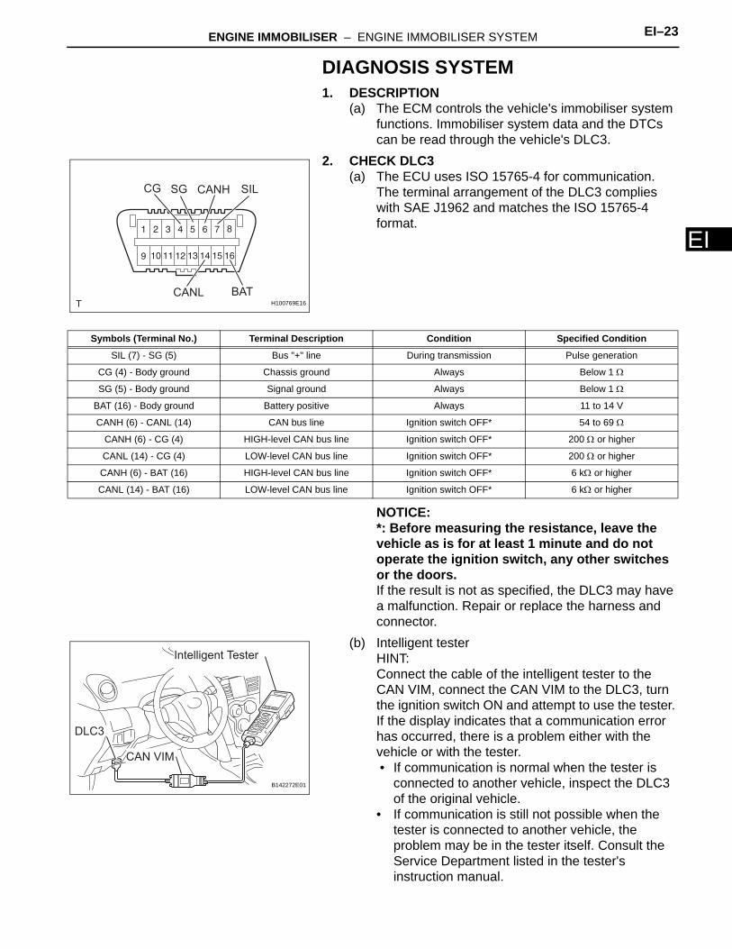
(2) Waveform 2
GND
B069241E01
Terminal IMI (A21-11) - EOM (A21-9)
Tool Setting 10 V/DIV., 500 ms/DIV.
Condition No key in ignition key cylinder → Key inserted
GND
B069242E02
Terminal IMO (A21-10) - EOM (A21-9)
Tool Setting 10 V/DIV., 500 ms/DIV.
Condition No key in ignition key cylinder → Key inserted
ENGINE IMMOBILISER – ENGINE IMMOBILISER SYSTEM EI–23
I
EDIAGNOSIS SYSTEM1. DESCRIPTION
(a) The ECM controls the vehicle's immobiliser system functions. Immobiliser system data and the DTCs can be read through the vehicle's DLC3.
2. CHECK DLC3(a) The ECU uses ISO 15765-4 for communication.
The terminal arrangement of the DLC3 complies with SAE J1962 and matches the ISO 15765-4 format.
NOTICE:*: Before measuring the resistance, leave the vehicle as is for at least 1 minute and do not operate the ignition switch, any other switches or the doors.If the result is not as specified, the DLC3 may have a malfunction. Repair or replace the harness and connector.
(b) Intelligent testerHINT:Connect the cable of the intelligent tester to the CAN VIM, connect the CAN VIM to the DLC3, turn the ignition switch ON and attempt to use the tester. If the display indicates that a communication error has occurred, there is a problem either with the vehicle or with the tester.• If communication is normal when the tester is
connected to another vehicle, inspect the DLC3 of the original vehicle.
• If communication is still not possible when the tester is connected to another vehicle, the problem may be in the tester itself. Consult the Service Department listed in the tester's instruction manual.
CG SG
BAT
SILCANH
CANLH100769E16
Symbols (Terminal No.) Terminal Description Condition Specified Condition
SIL (7) - SG (5) Bus "+" line During transmission Pulse generation
CG (4) - Body ground Chassis ground Always Below 1 Ω
SG (5) - Body ground Signal ground Always Below 1 Ω
BAT (16) - Body ground Battery positive Always 11 to 14 V
CANH (6) - CANL (14) CAN bus line Ignition switch OFF* 54 to 69 Ω
CANH (6) - CG (4) HIGH-level CAN bus line Ignition switch OFF* 200 Ω or higher
CANL (14) - CG (4) LOW-level CAN bus line Ignition switch OFF* 200 Ω or higher
CANH (6) - BAT (16) HIGH-level CAN bus line Ignition switch OFF* 6 kΩ or higher
CANL (14) - BAT (16) LOW-level CAN bus line Ignition switch OFF* 6 kΩ or higher
Intelligent Tester
CAN VIM
DLC3
B142272E01
EI–24 ENGINE IMMOBILISER – ENGINE IMMOBILISER SYSTEM
EI
3. INSPECT BATTERY VOLTAGEStandard voltage:
11 to 14 VIf the voltage is below 11 V, recharge or replace the battery before proceeding.
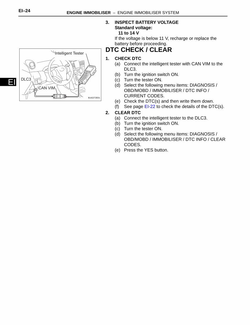
DTC CHECK / CLEAR1. CHECK DTC
(a) Connect the intelligent tester with CAN VIM to the DLC3.
(b) Turn the ignition switch ON.(c) Turn the tester ON.(d) Select the following menu items: DIAGNOSIS /
OBD/MOBD / IMMOBILISER / DTC INFO / CURRENT CODES.
(e) Check the DTC(s) and then write them down.(f) See page EI-22 to check the details of the DTC(s).
2. CLEAR DTC(a) Connect the intelligent tester to the DLC3.(b) Turn the ignition switch ON.(c) Turn the tester ON.(d) Select the following menu items: DIAGNOSIS /
OBD/MOBD / IMMOBILISER / DTC INFO / CLEAR CODES.
(e) Press the YES button.
Intelligent Tester
CAN VIM
DLC3
B142272E01
ENGINE IMMOBILISER – ENGINE IMMOBILISER SYSTEM EI–25
I
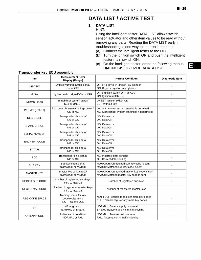
EDATA LIST / ACTIVE TEST1. DATA LIST
HINT:Using the intelligent tester DATA LIST allows switch, sensor, actuator and other item values to be read without removing any parts. Reading the DATA LIST early in troubleshooting is one way to shorten labor time.(a) Connect the intelligent tester to the DLC3.(b) Turn the ignition switch ON and push the intelligent
tester main switch ON.(c) On the intelligent tester, enter the following menus:
DIAGNOSIS/OBD MOBD/DATA LIST.Transponder key ECU assembly
Item Measurement Item/Display (Range) Normal Condition Diagnostic Note
KEY SW Unlock warning switch signal/ON or OFF
OFF: No key is in ignition key cylinderON: Key is in ignition key cylinder -
IG SW Ignition switch signal/ ON or OFF OFF: Ignition switch OFF or ACCON: Ignition switch ON -
IMMOBILISER Immobiliser system status/SET or UNSET
UNSET: Ignition switch ONSET: Without key -
PERMIT (START) Start control system starting control / OK or NG
OK: Start control system starting is permitted NG: Start control system starting is not permitted -
RESPONSE Transponder chip data/NG or OK
NG: Data errorOK: Data OK -
FRAME ERROR Transponder chip data/NG or OK
NG: Data errorOK: Data OK -
SERIAL NUMBER Transponder chip data/NG or OK
NG: Data errorOK: Data OK -
ENCRYPT CODE Transponder chip data/NG or OK
NG: Data errorOK: Data OK -
STATUS Transponder chip data/NG or OK
NG: Data errorOK: Data OK -
BCC Transponder chip signal/NG or OK
NG: Incorrect data sendingOK: Correct data sending -
SUB KEY Sub-key code signal/NOMATCH or MATCH
NOMATCH: Unmatched sub-key code is sentMATCH: Matched sub-key code is sent -
MASTER KEY Master key code signal/NOMATCH or MATCH
NOMATCH: Unmatched master key code is sentMATCH: Matched master key code is sent -
REGIST SUB CODE Number of registered sub-keys/min. 0, max. 15 Number of registered sub-keys -
REGIST MAS CODE Number of registered master keys/min. 0, max. 15 Number of registered master keys -
REG CODE SPACEMemory space for key
code registration/NOT FUL or FULL
NOT FUL: Possible to register more key codesFULL: Cannot register any more key codes -
+B +B judgment /NORMAL or BREAK
NORMAL: Battery supply is normalBREAK: Battery supply is malfunctioning -
ANTENNA COIL Antenna coil condition/NORMAL or FAIL
NORMAL: Antenna coil is normalFAIL: Antenna coil is malfunctioning -
EI–26 ENGINE IMMOBILISER – ENGINE IMMOBILISER SYSTEM
EI
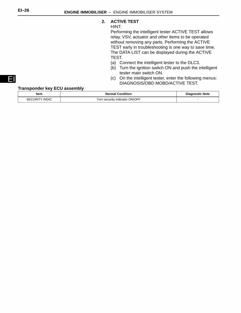
2. ACTIVE TESTHINT:Performing the intelligent tester ACTIVE TEST allows relay, VSV, actuator and other items to be operated without removing any parts. Performing the ACTIVE TEST early in troubleshooting is one way to save time. The DATA LIST can be displayed during the ACTIVE TEST.(a) Connect the intelligent tester to the DLC3.(b) Turn the ignition switch ON and push the intelligent
tester main switch ON.(c) On the intelligent tester, enter the following menus:
DIAGNOSIS/OBD MOBD/ACTIVE TEST.Transponder key ECU assembly
Item Normal Condition Diagnostic Note
SECURITY INDIC Turn security indicator ON/OFF -
ENGINE IMMOBILISER – ENGINE IMMOBILISER SYSTEM EI–27
I
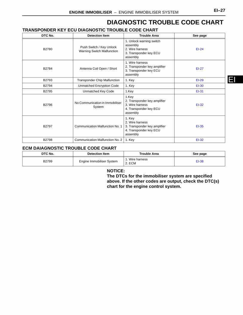
EDIAGNOSTIC TROUBLE CODE CHARTTRANSPONDER KEY ECU DIAGNOSTIC TROUBLE CODE CHART
ECM DAIAGNOSTIC TROUBLE CODE CHART
NOTICE:The DTCs for the immobiliser system are specified above. If the other codes are output, check the DTC(s) chart for the engine control system.
DTC No. Detection Item Trouble Area See page
B2780 Push Switch / Key Unlock Warning Switch Malfunction
1. Unlock warning switch assembly2. Wire harness3. Transponder key ECU assembly
EI-24
B2784 Antenna Coil Open / Short
1. Wire harness2. Transponder key amplifier3. Transponder key ECU assembly
EI-27
B2793 Transponder Chip Malfunction 1. Key EI-29
B2794 Unmatched Encryption Code 1. Key EI-30
B2795 Unmatched Key Code 1.Key EI-31
B2796 No Communication in Immobiliser System
1.Key2. Transponder key amplifier3. Wire harness4. Transponder key ECU assembly
EI-32
B2797 Communication Malfunction No. 1
1. Key2. Wire harness3. Transponder key amplifier4. Transponder key ECU assembly
EI-35
B2798 Communication Malfunction No. 2 1. Key EI-32
DTC No. Detection Item Trouble Area See page
B2799 Engine Immobiliser System 1. Wire harness2. ECM EI-38
EI–28 ENGINE IMMOBILISER – ENGINE IMMOBILISER SYSTEM
EI
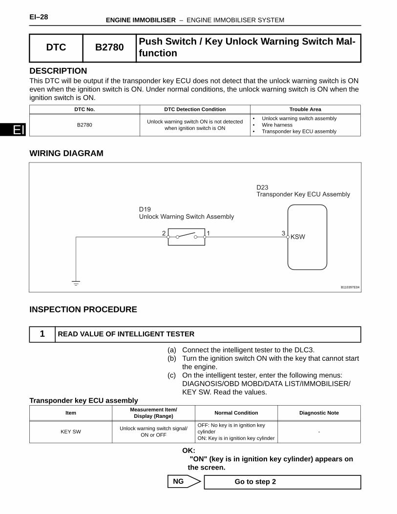
DESCRIPTIONThis DTC will be output if the transponder key ECU does not detect that the unlock warning switch is ON even when the ignition switch is ON. Under normal conditions, the unlock warning switch is ON when the ignition switch is ON.
WIRING DIAGRAM
INSPECTION PROCEDURE
(a) Connect the intelligent tester to the DLC3.(b) Turn the ignition switch ON with the key that cannot start
the engine.(c) On the intelligent tester, enter the following menus:
DIAGNOSIS/OBD MOBD/DATA LIST/IMMOBILISER/KEY SW. Read the values.
Transponder key ECU assembly
OK: "ON" (key is in ignition key cylinder) appears on the screen.
NG
DTC B2780 Push Switch / Key Unlock Warning Switch Mal-function
DTC No. DTC Detection Condition Trouble Area
B2780 Unlock warning switch ON is not detected when ignition switch is ON
• Unlock warning switch assembly• Wire harness• Transponder key ECU assembly
1 READ VALUE OF INTELLIGENT TESTER
KSW312
Transponder Key ECU Assembly
Unlock Warning Switch AssemblyD19
D23
B110397E04
Item Measurement Item/Display (Range) Normal Condition Diagnostic Note
KEY SW Unlock warning switch signal/ON or OFF
OFF: No key is in ignition key cylinderON: Key is in ignition key cylinder
-
Go to step 2
ENGINE IMMOBILISER – ENGINE IMMOBILISER SYSTEM EI–29
I
EOK
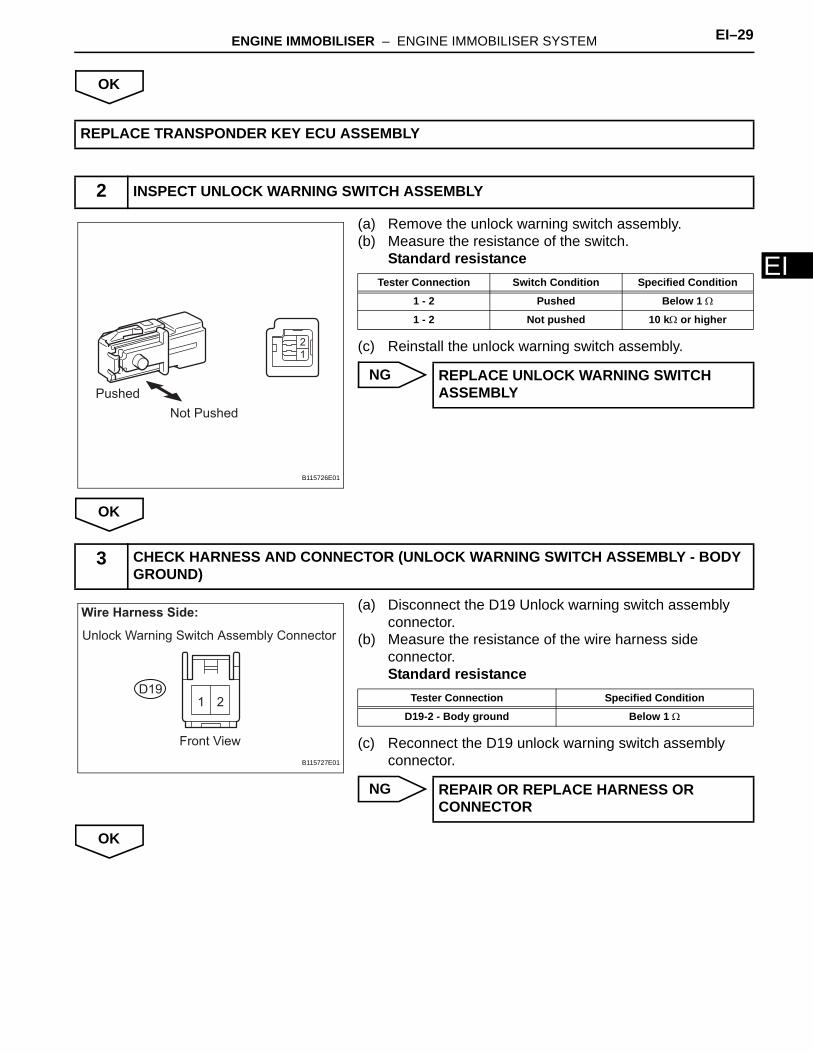
(a) Remove the unlock warning switch assembly.(b) Measure the resistance of the switch.
Standard resistance
(c) Reinstall the unlock warning switch assembly.
NG
OK
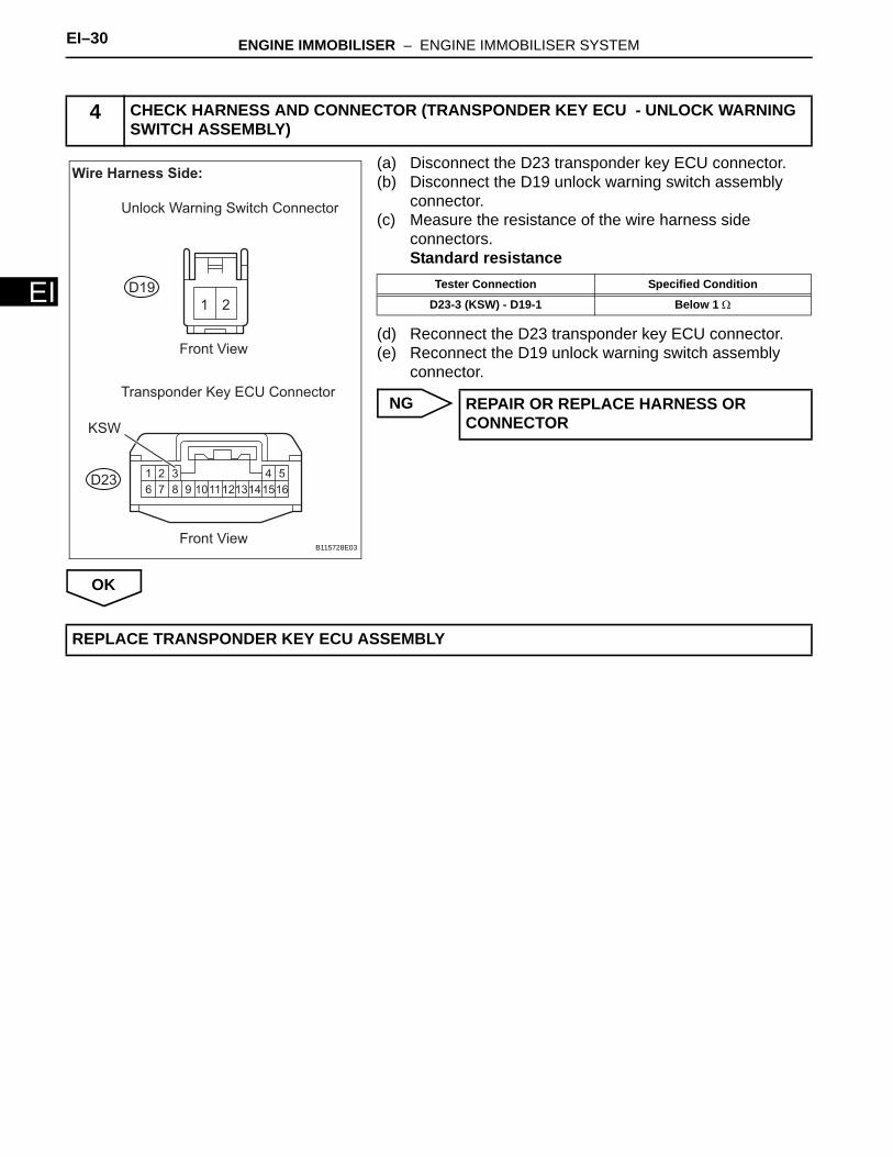
(a) Disconnect the D19 Unlock warning switch assembly connector.
(b) Measure the resistance of the wire harness side connector.Standard resistance
(c) Reconnect the D19 unlock warning switch assembly connector.
NG
OK
REPLACE TRANSPONDER KEY ECU ASSEMBLY
2 INSPECT UNLOCK WARNING SWITCH ASSEMBLY
2
1
Pushed
Not Pushed
B115726E01
Tester Connection Switch Condition Specified Condition
1 - 2 Pushed Below 1 Ω
1 - 2 Not pushed 10 kΩ or higher
REPLACE UNLOCK WARNING SWITCH ASSEMBLY
3 CHECK HARNESS AND CONNECTOR (UNLOCK WARNING SWITCH ASSEMBLY - BODY GROUND)
1 2
Wire Harness Side:
Unlock Warning Switch Assembly Connector
Front View
D19
B115727E01
Tester Connection Specified Condition
D19-2 - Body ground Below 1 Ω
REPAIR OR REPLACE HARNESS OR CONNECTOR
EI–30 ENGINE IMMOBILISER – ENGINE IMMOBILISER SYSTEM
EI
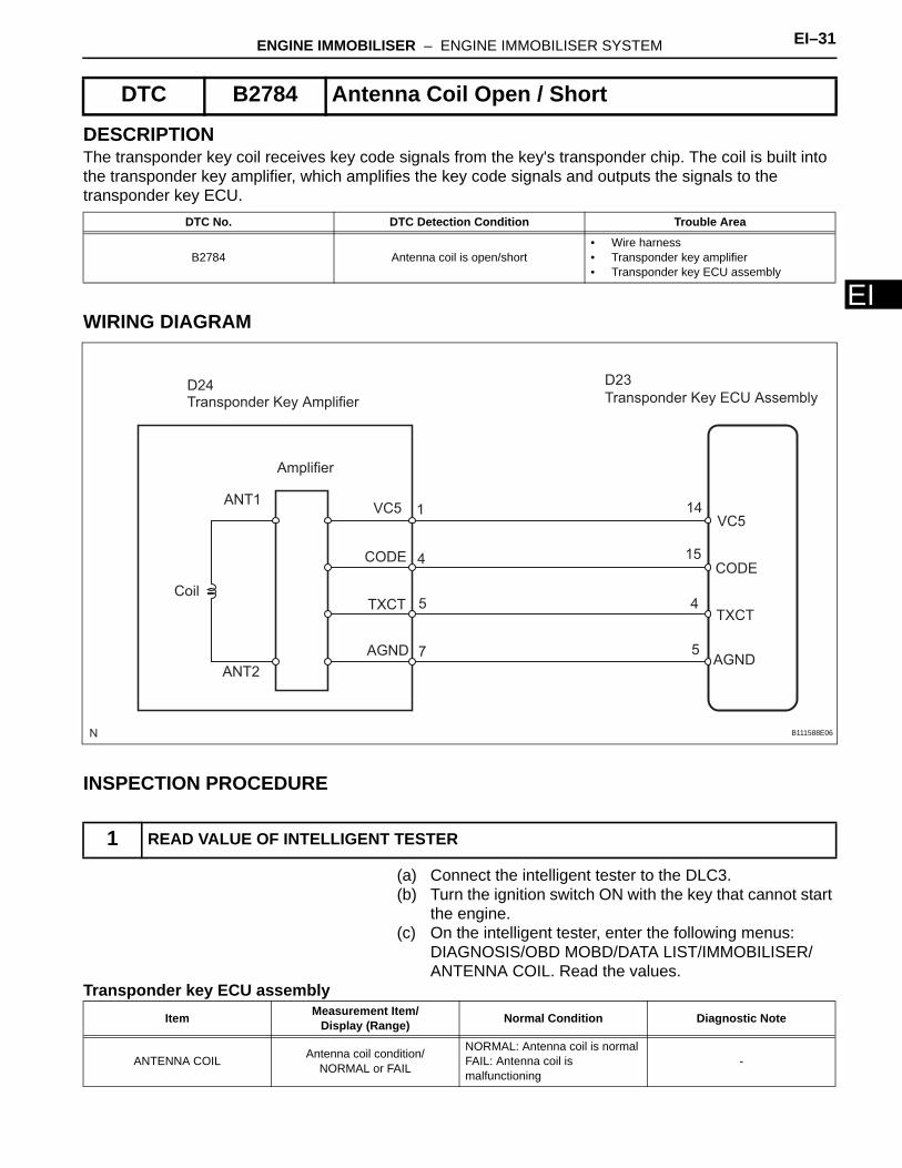
(a) Disconnect the D23 transponder key ECU connector.(b) Disconnect the D19 unlock warning switch assembly
connector.(c) Measure the resistance of the wire harness side
connectors.Standard resistance
(d) Reconnect the D23 transponder key ECU connector.(e) Reconnect the D19 unlock warning switch assembly
connector.
NG
OK
4 CHECK HARNESS AND CONNECTOR (TRANSPONDER KEY ECU - UNLOCK WARNING SWITCH ASSEMBLY)
1 2
1 2 3 4 5
6 7 8 9 151011121314 16
Wire Harness Side:
Unlock Warning Switch Connector
Transponder Key ECU Connector
Front View
Front View
KSW
D19
D23
B115728E03
Tester Connection Specified Condition
D23-3 (KSW) - D19-1 Below 1 Ω
REPAIR OR REPLACE HARNESS OR CONNECTOR
REPLACE TRANSPONDER KEY ECU ASSEMBLY
ENGINE IMMOBILISER – ENGINE IMMOBILISER SYSTEM EI–31
I
EDESCRIPTIONThe transponder key coil receives key code signals from the key's transponder chip. The coil is built into the transponder key amplifier, which amplifies the key code signals and outputs the signals to the transponder key ECU.
WIRING DIAGRAM
INSPECTION PROCEDURE
(a) Connect the intelligent tester to the DLC3.(b) Turn the ignition switch ON with the key that cannot start
the engine.(c) On the intelligent tester, enter the following menus:
DIAGNOSIS/OBD MOBD/DATA LIST/IMMOBILISER/ANTENNA COIL. Read the values.
Transponder key ECU assembly
DTC B2784 Antenna Coil Open / Short
DTC No. DTC Detection Condition Trouble Area
B2784 Antenna coil is open/short• Wire harness• Transponder key amplifier• Transponder key ECU assembly
1 READ VALUE OF INTELLIGENT TESTER
Transponder Key Amplifier
Amplifier
ANT1
ANT2
Coil
VC5
CODE
TXCT
AGND
Transponder Key ECU Assembly
VC5
CODE
TXCT
AGND
D24 D23
1
4
5
7
14
15
4
5
B111588E06
Item Measurement Item/Display (Range) Normal Condition Diagnostic Note
ANTENNA COIL Antenna coil condition/NORMAL or FAIL
NORMAL: Antenna coil is normalFAIL: Antenna coil is malfunctioning
-
EI–32 ENGINE IMMOBILISER – ENGINE IMMOBILISER SYSTEM
EI
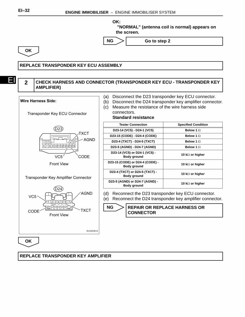
OK: "NORMAL" (antenna coil is normal) appears on the screen.
NG
OK
(a) Disconnect the D23 transponder key ECU connector.(b) Disconnect the D24 transponder key amplifier connector.(c) Measure the resistance of the wire harness side
connectors.Standard resistance
(d) Reconnect the D23 transponder key ECU connector.(e) Reconnect the D24 transponder key amplifier connector.
NG
OK
Go to step 2
REPLACE TRANSPONDER KEY ECU ASSEMBLY
2 CHECK HARNESS AND CONNECTOR (TRANSPONDER KEY ECU - TRANSPONDER KEY AMPLIFIER)
1 2 3 4 5
6 7 8 9 151011121314 16
1 2 3 4 5 6 7
Wire Harness Side:
Transponder Key ECU Connector
Transponder Key Amplifier Connector
Front View
Front View
TXCT
TXCT
AGND
AGND
VC5
VC5
CODE
CODE
D23
D24
B110403E15
Tester Connection Specified Condition
D23-14 (VC5) - D24-1 (VC5) Below 1 Ω
D23-15 (CODE) - D24-4 (CODE) Below 1 Ω
D23-4 (TXCT) - D24-5 (TXCT) Below 1 Ω
D23-5 (AGND) - D24-7 (AGND) Below 1 Ω
D23-14 (VC5) or D24-1 (VC5) - Body ground 10 kΩ or higher
D23-15 (CODE) or D24-4 (CODE) - Body ground 10 kΩ or higher
D23-4 (TXCT) or D24-5 (TXCT) - Body ground 10 kΩ or higher
D23-5 (AGND) or D24-7 (AGND) - Body ground 10 kΩ or higher
REPAIR OR REPLACE HARNESS OR CONNECTOR
REPLACE TRANSPONDER KEY AMPLIFIER
ENGINE IMMOBILISER – ENGINE IMMOBILISER SYSTEM EI–33
I
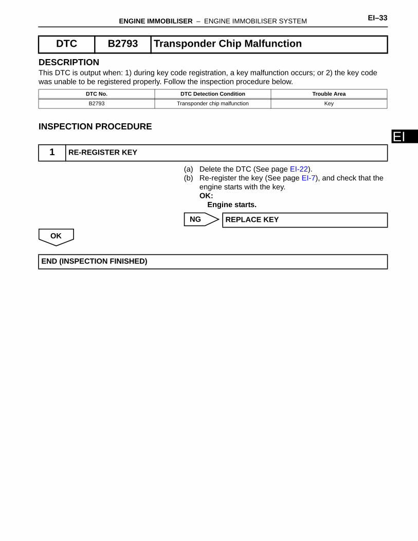
EDESCRIPTIONThis DTC is output when: 1) during key code registration, a key malfunction occurs; or 2) the key code was unable to be registered properly. Follow the inspection procedure below.
INSPECTION PROCEDURE
(a) Delete the DTC (See page EI-22). (b) Re-register the key (See page EI-7), and check that the
engine starts with the key. OK:
Engine starts.
NG
OK
DTC B2793 Transponder Chip Malfunction
DTC No. DTC Detection Condition Trouble Area
B2793 Transponder chip malfunction Key
1 RE-REGISTER KEY
REPLACE KEY
END (INSPECTION FINISHED)
EI–34 ENGINE IMMOBILISER – ENGINE IMMOBILISER SYSTEM
EI
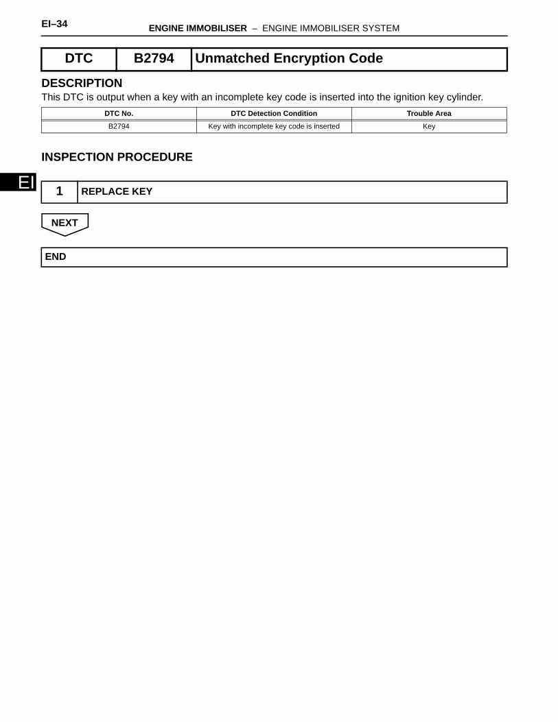
DESCRIPTIONThis DTC is output when a key with an incomplete key code is inserted into the ignition key cylinder.
INSPECTION PROCEDURE
NEXT
DTC B2794 Unmatched Encryption Code
DTC No. DTC Detection Condition Trouble Area
B2794 Key with incomplete key code is inserted Key
1 REPLACE KEY
END
ENGINE IMMOBILISER – ENGINE IMMOBILISER SYSTEM EI–35
I
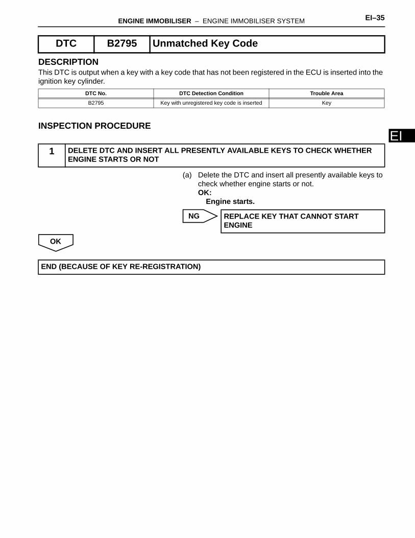
EDESCRIPTIONThis DTC is output when a key with a key code that has not been registered in the ECU is inserted into the ignition key cylinder.
INSPECTION PROCEDURE
(a) Delete the DTC and insert all presently available keys to check whether engine starts or not.OK:
Engine starts.
NG
OK
DTC B2795 Unmatched Key Code
DTC No. DTC Detection Condition Trouble Area
B2795 Key with unregistered key code is inserted Key
1 DELETE DTC AND INSERT ALL PRESENTLY AVAILABLE KEYS TO CHECK WHETHER ENGINE STARTS OR NOT
REPLACE KEY THAT CANNOT START ENGINE
END (BECAUSE OF KEY RE-REGISTRATION)
EI–36 ENGINE IMMOBILISER – ENGINE IMMOBILISER SYSTEM
EI
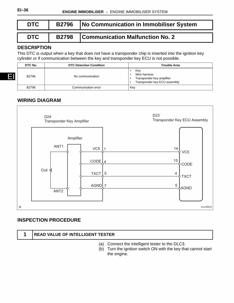
DESCRIPTIONThis DTC is output when a key that does not have a transponder chip is inserted into the ignition key cylinder or if communication between the key and transponder key ECU is not possible.
WIRING DIAGRAM
INSPECTION PROCEDURE
(a) Connect the intelligent tester to the DLC3.(b) Turn the ignition switch ON with the key that cannot start
the engine.
DTC B2796 No Communication in Immobiliser System
DTC B2798 Communication Malfunction No. 2
DTC No. DTC Detection Condition Trouble Area
B2796 No communication
• Key• Wire harness• Transponder key amplifier• Transponder key ECU assembly
B2798 Communication error Key
1 READ VALUE OF INTELLIGENT TESTER
Transponder Key Amplifier
Amplifier
ANT1
ANT2
Coil
VC5
CODE
TXCT
AGND
Transponder Key ECU Assembly
VC5
CODE
TXCT
AGND
D24 D23
1
4
5
7
14
15
4
5
B111588E06
ENGINE IMMOBILISER – ENGINE IMMOBILISER SYSTEM EI–37
I
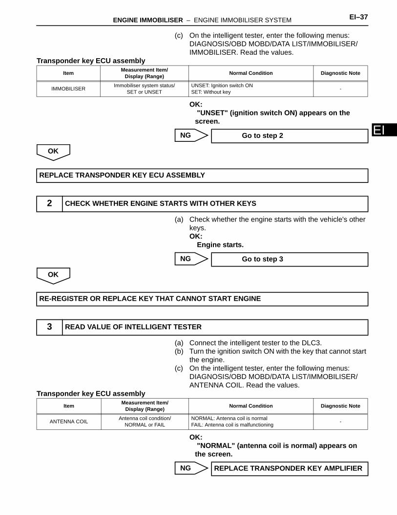
E(c) On the intelligent tester, enter the following menus: DIAGNOSIS/OBD MOBD/DATA LIST/IMMOBILISER/IMMOBILISER. Read the values.
Transponder key ECU assembly
OK: "UNSET" (ignition switch ON) appears on the screen.
NG
OK
(a) Check whether the engine starts with the vehicle's other keys.OK:
Engine starts.
NG
OK
(a) Connect the intelligent tester to the DLC3.(b) Turn the ignition switch ON with the key that cannot start
the engine.(c) On the intelligent tester, enter the following menus:
DIAGNOSIS/OBD MOBD/DATA LIST/IMMOBILISER/ANTENNA COIL. Read the values.
Transponder key ECU assembly
OK: "NORMAL" (antenna coil is normal) appears on the screen.
NG
Item Measurement Item/Display (Range) Normal Condition Diagnostic Note
IMMOBILISER Immobiliser system status/SET or UNSET
UNSET: Ignition switch ONSET: Without key -
Go to step 2
REPLACE TRANSPONDER KEY ECU ASSEMBLY
2 CHECK WHETHER ENGINE STARTS WITH OTHER KEYS
Go to step 3
RE-REGISTER OR REPLACE KEY THAT CANNOT START ENGINE
3 READ VALUE OF INTELLIGENT TESTER
Item Measurement Item/Display (Range) Normal Condition Diagnostic Note
ANTENNA COIL Antenna coil condition/NORMAL or FAIL
NORMAL: Antenna coil is normalFAIL: Antenna coil is malfunctioning -
REPLACE TRANSPONDER KEY AMPLIFIER
EI–38 ENGINE IMMOBILISER – ENGINE IMMOBILISER SYSTEM
EI
OK
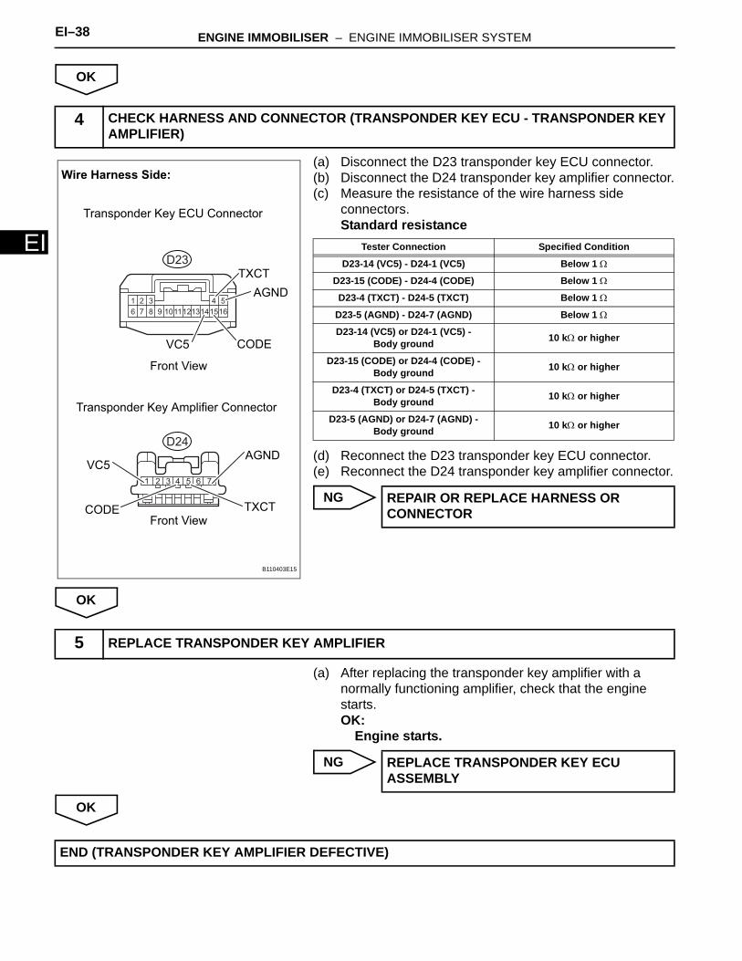
(a) Disconnect the D23 transponder key ECU connector.(b) Disconnect the D24 transponder key amplifier connector.(c) Measure the resistance of the wire harness side
connectors.Standard resistance
(d) Reconnect the D23 transponder key ECU connector.(e) Reconnect the D24 transponder key amplifier connector.
NG
OK
(a) After replacing the transponder key amplifier with a normally functioning amplifier, check that the engine starts.OK:
Engine starts.
NG
OK
4 CHECK HARNESS AND CONNECTOR (TRANSPONDER KEY ECU - TRANSPONDER KEY AMPLIFIER)
1 2 3 4 5
6 7 8 9 151011121314 16
1 2 3 4 5 6 7
Wire Harness Side:
Transponder Key ECU Connector
Transponder Key Amplifier Connector
Front View
Front View
TXCT
TXCT
AGND
AGND
VC5
VC5
CODE
CODE
D23
D24
B110403E15
Tester Connection Specified Condition
D23-14 (VC5) - D24-1 (VC5) Below 1 Ω
D23-15 (CODE) - D24-4 (CODE) Below 1 Ω
D23-4 (TXCT) - D24-5 (TXCT) Below 1 Ω
D23-5 (AGND) - D24-7 (AGND) Below 1 Ω
D23-14 (VC5) or D24-1 (VC5) - Body ground 10 kΩ or higher
D23-15 (CODE) or D24-4 (CODE) - Body ground 10 kΩ or higher
D23-4 (TXCT) or D24-5 (TXCT) - Body ground 10 kΩ or higher
D23-5 (AGND) or D24-7 (AGND) - Body ground 10 kΩ or higher
REPAIR OR REPLACE HARNESS OR CONNECTOR
5 REPLACE TRANSPONDER KEY AMPLIFIER
REPLACE TRANSPONDER KEY ECU ASSEMBLY
END (TRANSPONDER KEY AMPLIFIER DEFECTIVE)
ENGINE IMMOBILISER – ENGINE IMMOBILISER SYSTEM EI–39
I
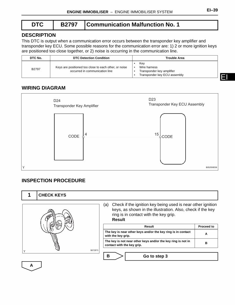
EDESCRIPTIONThis DTC is output when a communication error occurs between the transponder key amplifier and transponder key ECU. Some possible reasons for the communication error are: 1) 2 or more ignition keys are positioned too close together, or 2) noise is occurring in the communication line.
WIRING DIAGRAM
INSPECTION PROCEDURE
(a) Check if the ignition key being used is near other ignition keys, as shown in the illustration. Also, check if the key ring is in contact with the key grip.Result
B
A
DTC B2797 Communication Malfunction No. 1
DTC No. DTC Detection Condition Trouble Area
B2797 Keys are positioned too close to each other, or noise occurred in communication line
• Key• Wire harness• Transponder key amplifier• Transponder key ECU assembly
1 CHECK KEYS
Transponder Key Amplifier Transponder Key ECU Assembly
CODECODE
D24 D23
4 15
B052550E08
B072873
Result Proceed to
The key is near other keys and/or the key ring is in contact with the key grip. A
The key is not near other keys and/or the key ring is not in contact with the key grip. B
Go to step 3
EI–40 ENGINE IMMOBILISER – ENGINE IMMOBILISER SYSTEM
EI
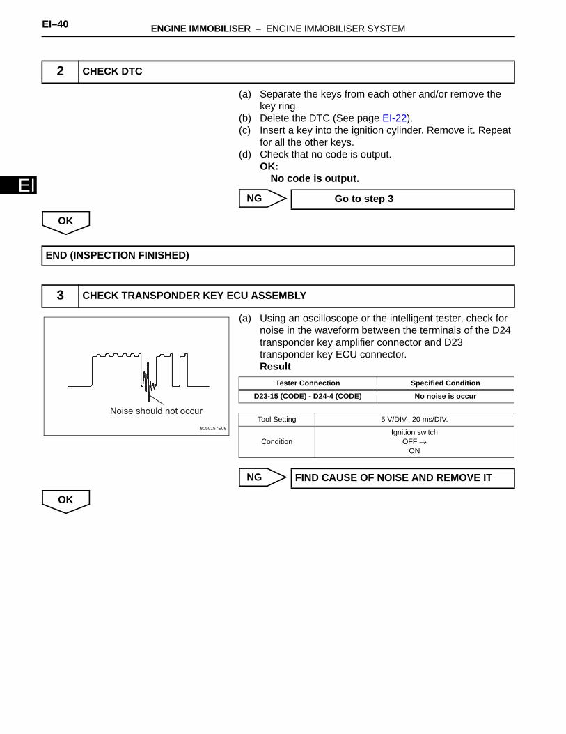
(a) Separate the keys from each other and/or remove the key ring.
(b) Delete the DTC (See page EI-22). (c) Insert a key into the ignition cylinder. Remove it. Repeat
for all the other keys.(d) Check that no code is output.
OK: No code is output.
NG
OK
(a) Using an oscilloscope or the intelligent tester, check for noise in the waveform between the terminals of the D24 transponder key amplifier connector and D23 transponder key ECU connector.Result
NG
OK
2 CHECK DTC
Go to step 3
END (INSPECTION FINISHED)
3 CHECK TRANSPONDER KEY ECU ASSEMBLY
Noise should not occur
B050157E08
Tester Connection Specified Condition
D23-15 (CODE) - D24-4 (CODE) No noise is occur
Tool Setting 5 V/DIV., 20 ms/DIV.
ConditionIgnition switch
OFF →ON
FIND CAUSE OF NOISE AND REMOVE IT
ENGINE IMMOBILISER – ENGINE IMMOBILISER SYSTEM EI–41
I
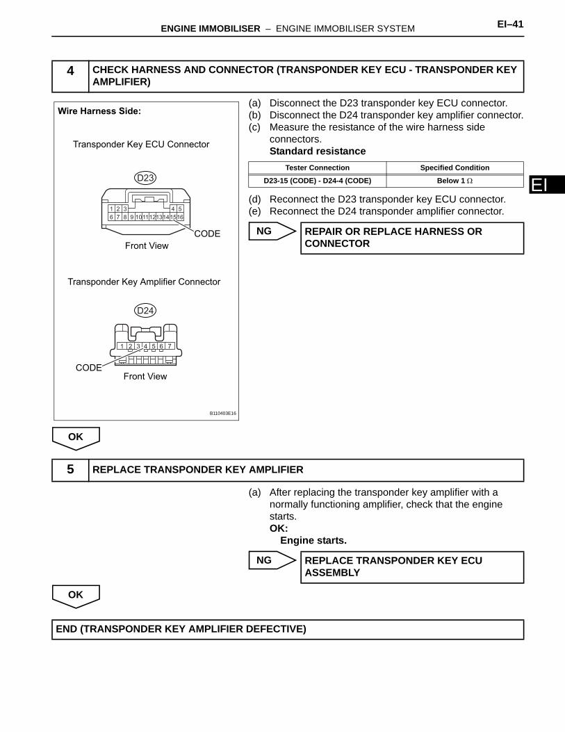
E(a) Disconnect the D23 transponder key ECU connector.(b) Disconnect the D24 transponder key amplifier connector.(c) Measure the resistance of the wire harness side
connectors.Standard resistance
(d) Reconnect the D23 transponder key ECU connector.(e) Reconnect the D24 transponder amplifier connector.
NG
OK
(a) After replacing the transponder key amplifier with a normally functioning amplifier, check that the engine starts.OK:
Engine starts.
NG
OK
4 CHECK HARNESS AND CONNECTOR (TRANSPONDER KEY ECU - TRANSPONDER KEY AMPLIFIER)
1 2 3 4 5
6 7 8 9 151011121314 16
1 2 3 4 5 6 7
Wire Harness Side:
Transponder Key ECU Connector
Transponder Key Amplifier Connector
Front View
Front View
CODE
CODE
D23
D24
B110403E16
Tester Connection Specified Condition
D23-15 (CODE) - D24-4 (CODE) Below 1 Ω
REPAIR OR REPLACE HARNESS OR CONNECTOR
5 REPLACE TRANSPONDER KEY AMPLIFIER
REPLACE TRANSPONDER KEY ECU ASSEMBLY
END (TRANSPONDER KEY AMPLIFIER DEFECTIVE)
EI–42 ENGINE IMMOBILISER – ENGINE IMMOBILISER SYSTEM
EI
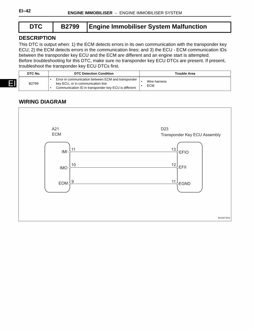
DESCRIPTIONThis DTC is output when: 1) the ECM detects errors in its own communication with the transponder key ECU; 2) the ECM detects errors in the communication lines; and 3) the ECU - ECM communication IDs between the transponder key ECU and the ECM are different and an engine start is attempted.Before troubleshooting for this DTC, make sure no transponder key ECU DTCs are present. If present, troubleshoot the transponder key ECU DTCs first.
WIRING DIAGRAM
DTC B2799 Engine Immobiliser System Malfunction
DTC No. DTC Detection Condition Trouble Area
B2799• Error in communication between ECM and transponder
key ECU, or in communication line• Communication ID in transponder key ECU is different
• Wire harness• ECM
ECM Transponder Key ECU Assembly
EFIO
EFII
EGND
IMI
IMO
EOM
A21 D23
11
10
9
13
12
11
B115877E03
ENGINE IMMOBILISER – ENGINE IMMOBILISER SYSTEM EI–43
I
EINSPECTION PROCEDURE
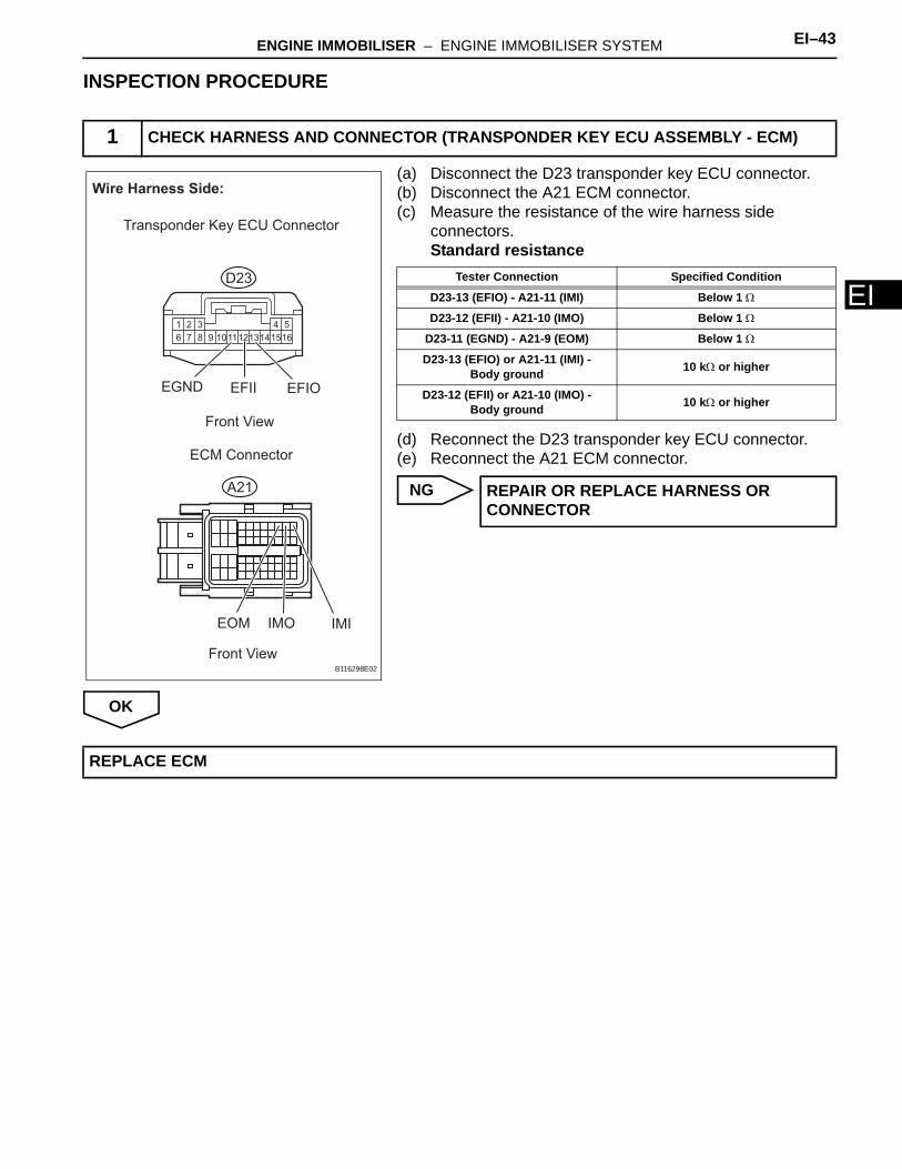
(a) Disconnect the D23 transponder key ECU connector.(b) Disconnect the A21 ECM connector.(c) Measure the resistance of the wire harness side
connectors.Standard resistance
(d) Reconnect the D23 transponder key ECU connector.(e) Reconnect the A21 ECM connector.
NG
OK
1 CHECK HARNESS AND CONNECTOR (TRANSPONDER KEY ECU ASSEMBLY - ECM)
1 2 3 4 5
6 7 8 9 151011121314 16
Wire Harness Side:
Transponder Key ECU Connector
ECM Connector
IMIIMOEOM
EFIOEFIIEGND
A21
D23
Front View
Front ViewB116298E02
Tester Connection Specified Condition
D23-13 (EFIO) - A21-11 (IMI) Below 1 Ω
D23-12 (EFII) - A21-10 (IMO) Below 1 Ω
D23-11 (EGND) - A21-9 (EOM) Below 1 Ω
D23-13 (EFIO) or A21-11 (IMI) - Body ground 10 kΩ or higher
D23-12 (EFII) or A21-10 (IMO) - Body ground 10 kΩ or higher
REPAIR OR REPLACE HARNESS OR CONNECTOR
REPLACE ECM
EI–44 ENGINE IMMOBILISER – ENGINE IMMOBILISER SYSTEM
EI
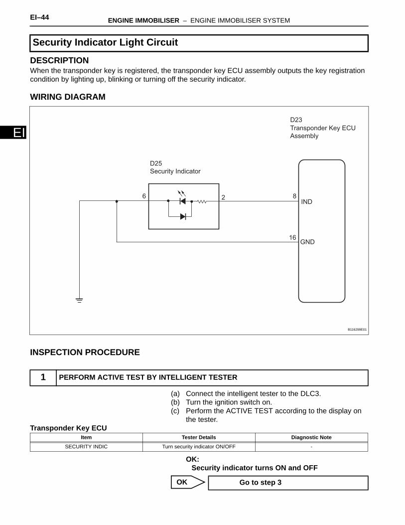
DESCRIPTIONWhen the transponder key is registered, the transponder key ECU assembly outputs the key registration condition by lighting up, blinking or turning off the security indicator.
WIRING DIAGRAM
INSPECTION PROCEDURE
(a) Connect the intelligent tester to the DLC3.(b) Turn the ignition switch on.(c) Perform the ACTIVE TEST according to the display on
the tester.Transponder Key ECU
OK:Security indicator turns ON and OFF
OK
Security Indicator Light Circuit
1 PERFORM ACTIVE TEST BY INTELLIGENT TESTER
IND
GND
Security Indicator
8
16
26
Transponder Key ECU
Assembly
D25
D23
B116299E01
Item Tester Details Diagnostic Note
SECURITY INDIC Turn security indicator ON/OFF -
Go to step 3
ENGINE IMMOBILISER – ENGINE IMMOBILISER SYSTEM EI–45
I
ENG
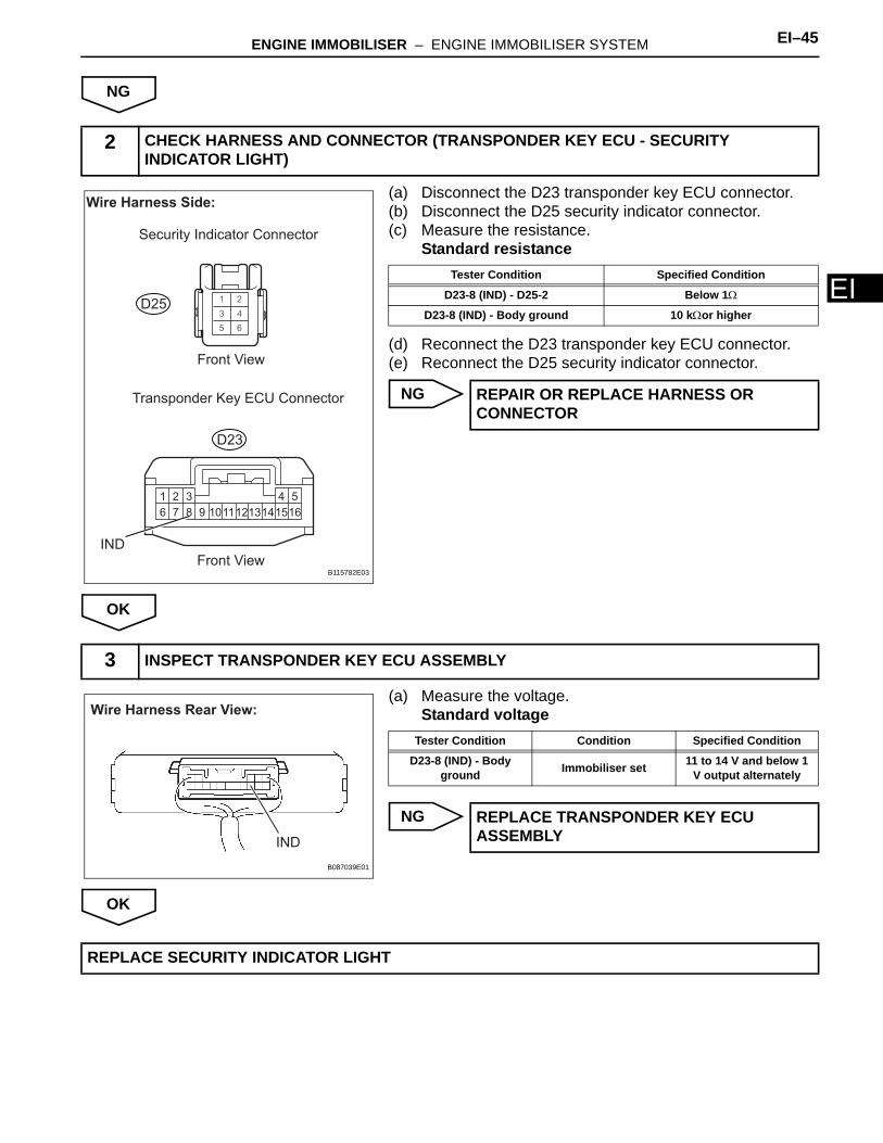
(a) Disconnect the D23 transponder key ECU connector.(b) Disconnect the D25 security indicator connector.(c) Measure the resistance.
Standard resistance
(d) Reconnect the D23 transponder key ECU connector.(e) Reconnect the D25 security indicator connector.
NG
OK
(a) Measure the voltage.Standard voltage
NG
OK
2 CHECK HARNESS AND CONNECTOR (TRANSPONDER KEY ECU - SECURITY INDICATOR LIGHT)
1 2 3 4 5
6 7 8 9 151011121314 16
IND
Wire Harness Side:
Security Indicator Connector
Front View
Front View
Transponder Key ECU Connector
D23
D25
B115782E03
Tester Condition Specified Condition
D23-8 (IND) - D25-2 Below 1Ω
D23-8 (IND) - Body ground 10 kΩor higher
REPAIR OR REPLACE HARNESS OR CONNECTOR
3 INSPECT TRANSPONDER KEY ECU ASSEMBLY
Wire Harness Rear View:
IND
B087039E01
Tester Condition Condition Specified Condition
D23-8 (IND) - Body ground Immobiliser set 11 to 14 V and below 1
V output alternately
REPLACE TRANSPONDER KEY ECU ASSEMBLY
REPLACE SECURITY INDICATOR LIGHT
EI–46 ENGINE IMMOBILISER – ENGINE IMMOBILISER SYSTEM
EI
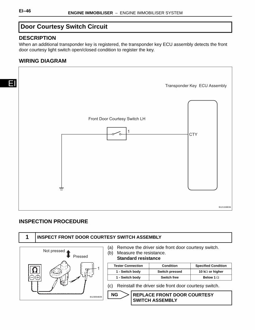
DESCRIPTIONWhen an additional transponder key is registered, the transponder key ECU assembly detects the front door courtesy light switch open/closed condition to register the key.
WIRING DIAGRAM
INSPECTION PROCEDURE
(a) Remove the driver side front door courtesy switch.(b) Measure the resistance.
Standard resistance
(c) Reinstall the driver side front door courtesy switch.
NG
Door Courtesy Switch Circuit
1 INSPECT FRONT DOOR COURTESY SWITCH ASSEMBLY
Transponder Key ECU Assembly
CTY
Front Door Courtesy Switch LH
1
B121328E06
Pressed
Not pressed
1
B123004E05
Tester Connection Condition Specified Condition
1 - Switch body Switch pressed 10 kΩ or higher
1 - Switch body Switch free Below 1 Ω
REPLACE FRONT DOOR COURTESY SWITCH ASSEMBLY

ENGINE IMMOBILISER – ENGINE IMMOBILISER SYSTEM EI–47
I
EOK
(a) Disconnect the D23 ECU connector.(b) Measure the resistance.
Standard resistance
(c) Reconnect the ECU connector.
NG
OK
2 CHECK HARNESS AND CONNECTOR (FRONT DOOR COURTESY SWITCH CIRCUIT)
Wire Harness Rear View:
CTY
D23
B087040E05
Tester Connection Condition Specified Condition
D23-7 (CTY) - Body ground
Courtesy switch pushed 10 kΩ or higher
D23-7 (CTY) - Body ground Courtesy switch free Below 1 Ω
REPAIR OR REPLACE HARNESS OR CONNECTOR
PROCEED TO NEXT CIRCUIT INSPECTION SHOWN IN PROBLEM SYMPTOMS TABLE
EI–48 ENGINE IMMOBILISER – ENGINE IMMOBILISER SYSTEM
EI
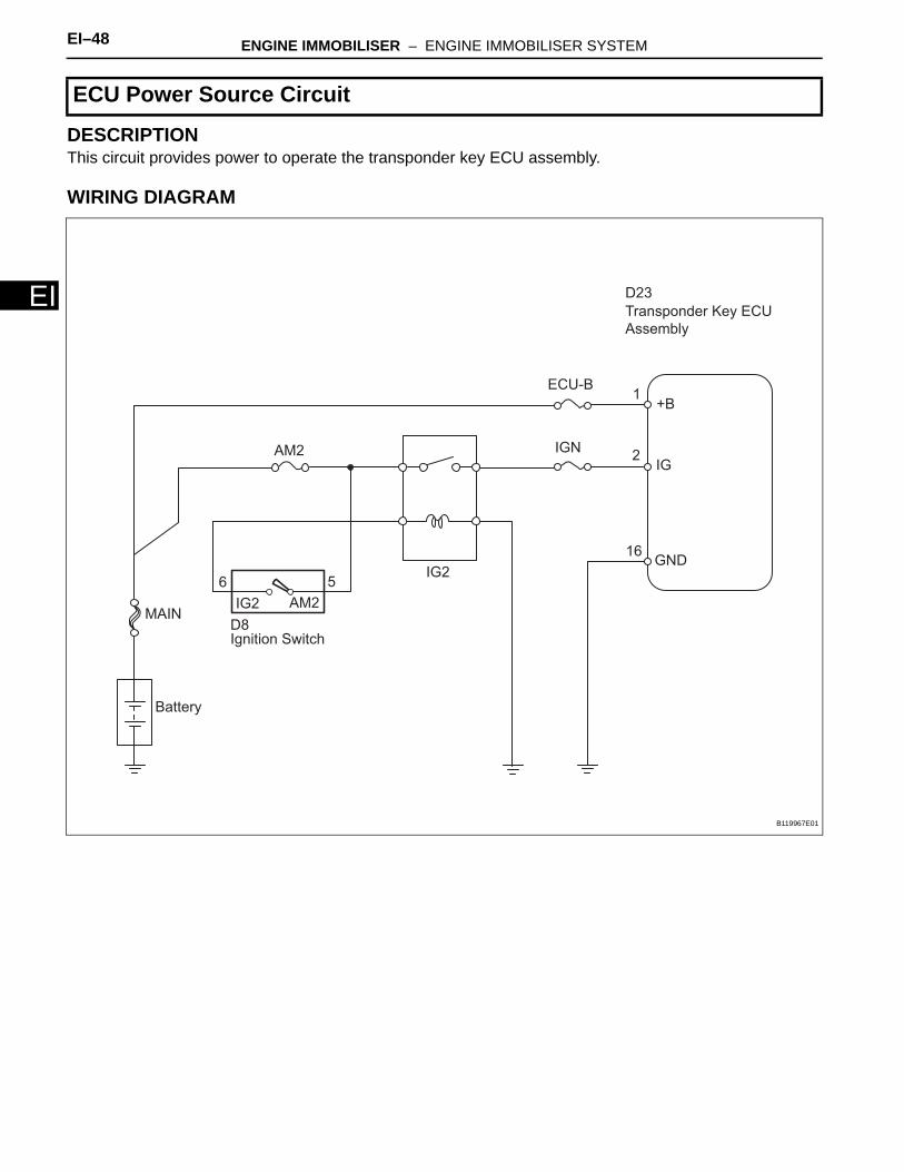
DESCRIPTIONThis circuit provides power to operate the transponder key ECU assembly.
WIRING DIAGRAM
ECU Power Source Circuit
Transponder Key ECU
Assembly
IG2
Ignition Switch
Battery
MAIN
ECU-B
IGN
+B
IG
GND
AM2
AM2IG2
D8
D23
1
2
16
6 5
B119967E01
ENGINE IMMOBILISER – ENGINE IMMOBILISER SYSTEM EI–49
I
EINSPECTION PROCEDURE
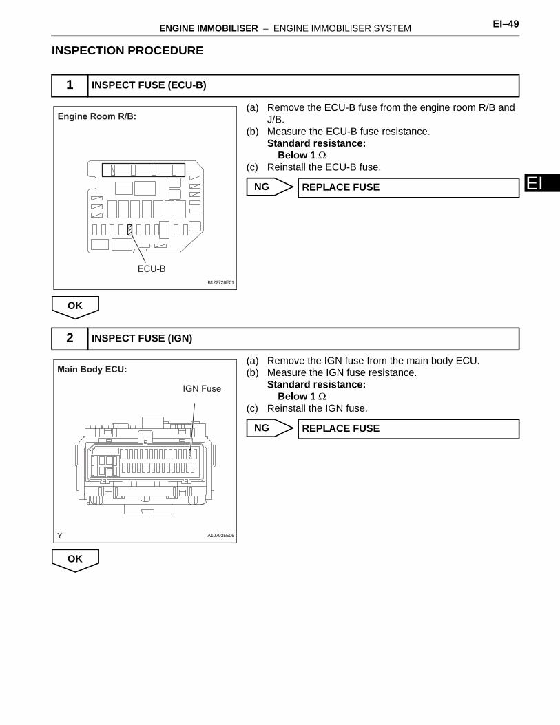
(a) Remove the ECU-B fuse from the engine room R/B and J/B.
(b) Measure the ECU-B fuse resistance.Standard resistance:
Below 1 Ω(c) Reinstall the ECU-B fuse.
NG
OK
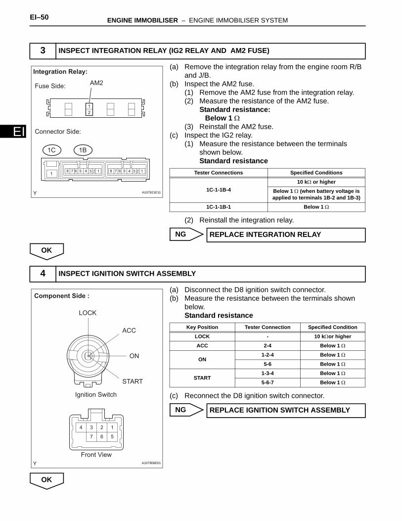
(a) Remove the IGN fuse from the main body ECU.(b) Measure the IGN fuse resistance.
Standard resistance: Below 1 Ω
(c) Reinstall the IGN fuse.
NG
OK
1 INSPECT FUSE (ECU-B)
ECU-B
Engine Room R/B:
B122728E01
REPLACE FUSE
2 INSPECT FUSE (IGN)
IGN Fuse
Main Body ECU:
A107935E06
REPLACE FUSE
EI–50 ENGINE IMMOBILISER – ENGINE IMMOBILISER SYSTEM
EI
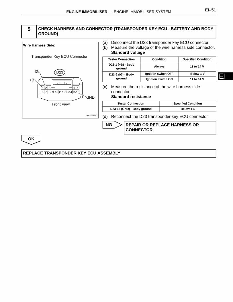
(a) Remove the integration relay from the engine room R/B and J/B.
(b) Inspect the AM2 fuse.(1) Remove the AM2 fuse from the integration relay.(2) Measure the resistance of the AM2 fuse.
Standard resistance:Below 1 Ω
(3) Reinstall the AM2 fuse.(c) Inspect the IG2 relay.
(1) Measure the resistance between the terminals shown below.Standard resistance
(2) Reinstall the integration relay.
NG
OK
(a) Disconnect the D8 ignition switch connector.(b) Measure the resistance between the terminals shown
below.Standard resistance
(c) Reconnect the D8 ignition switch connector.
NG
OK
3 INSPECT INTEGRATION RELAY (IG2 RELAY AND AM2 FUSE)
1235 4678 1235 46781
Fuse Side:
Connector Side:
Integration Relay:
AM2
1
2
1B1C
A107921E11
Tester Connections Specified Conditions
1C-1-1B-410 kΩ or higher
Below 1 Ω (when battery voltage is applied to terminals 1B-2 and 1B-3)
1C-1-1B-1 Below 1 Ω
REPLACE INTEGRATION RELAY
4 INSPECT IGNITION SWITCH ASSEMBLY
123
567
4
Ignition Switch
LOCK
ACC
ON
START
Front View
Component Side :
A107906E01
Key Position Tester Connection Specified Condition
LOCK - 10 kΩor higher
ACC 2-4 Below 1 Ω
ON1-2-4 Below 1 Ω
5-6 Below 1 Ω
START1-3-4 Below 1 Ω
5-6-7 Below 1 Ω
REPLACE IGNITION SWITCH ASSEMBLY
ENGINE IMMOBILISER – ENGINE IMMOBILISER SYSTEM EI–51
I
E(a) Disconnect the D23 transponder key ECU connector.(b) Measure the voltage of the wire harness side connector.
Standard voltage
(c) Measure the resistance of the wire harness side connector.Standard resistance
(d) Reconnect the D23 transponder key ECU connector.
NG
OK
5 CHECK HARNESS AND CONNECTOR (TRANSPONDER KEY ECU - BATTERY AND BODY GROUND)
1 2 3 4 5
6 7 8 9 151011121314 16
Wire Harness Side:
+B
IG
GND
Transponder Key ECU Connector
Front View
D23
B110782E07
Tester Connection Condition Specified Condition
D23-1 (+B) - Body ground Always 11 to 14 V
D23-2 (IG) - Body ground
Ignition switch OFF Below 1 V
Ignition switch ON 11 to 14 V
Tester Connection Specified Condition
D23-16 (GND) - Body ground Below 1 Ω
REPAIR OR REPLACE HARNESS OR CONNECTOR
REPLACE TRANSPONDER KEY ECU ASSEMBLY


![Op-com Immobiliser Guide[1]](https://img.pdfslide.us/doc/110x75/55cf9bfd550346d033a823bd/op-com-immobiliser-guide1.jpg)