Embed Size (px)
Citation preview
1
ENGG 1203 Tutorial
Sequential Logic
19/26 Sept
Learning Objectives
Design combinational circuits
Calculate timing in sequential circuits
Design a finite state machine
News
Ack.: HKU ELEC1008, ISU CprE 281x, PSU
CMPEN270, Wikipedia
Q1
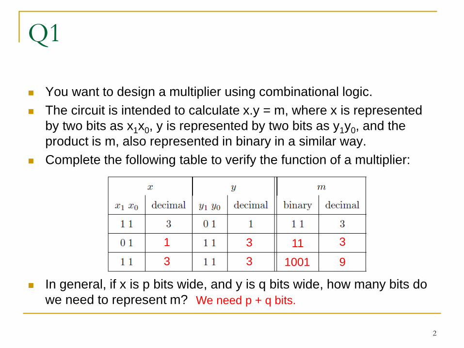
You want to design a multiplier using combinational logic.
The circuit is intended to calculate x.y = m, where x is represented
by two bits as x1x0, y is represented by two bits as y1y0, and the
product is m, also represented in binary in a similar way.
Complete the following table to verify the function of a multiplier:
In general, if x is p bits wide, and y is q bits wide, how many bits do
we need to represent m?
2
1 3 3
3 3 9
11
1001
We need p + q bits.
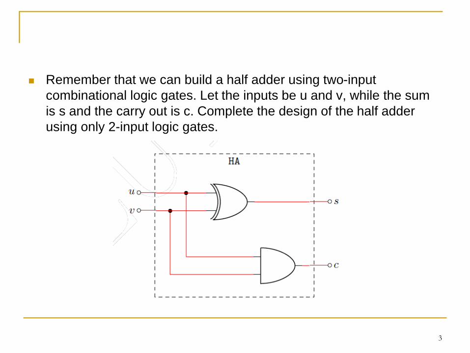
Remember that we can build a half adder using two-input
combinational logic gates. Let the inputs be u and v, while the sum
is s and the carry out is c. Complete the design of the half adder
using only 2-input logic gates.
3
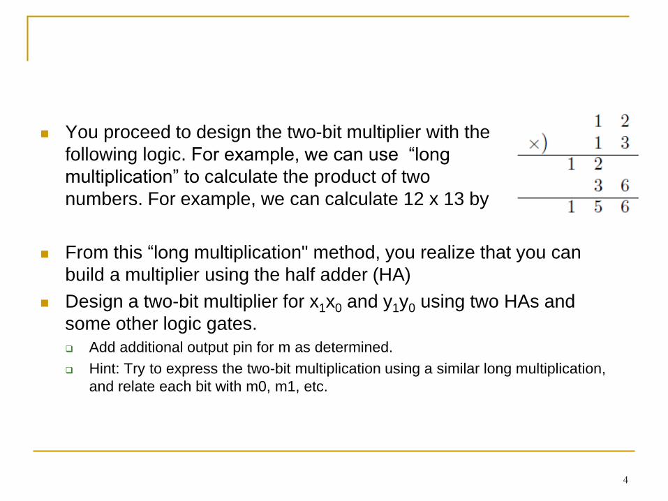
You proceed to design the two-bit multiplier with the
following logic. For example, we can use “long
multiplication” to calculate the product of two
numbers. For example, we can calculate 12 x 13 by
From this “long multiplication" method, you realize that you can
build a multiplier using the half adder (HA)
Design a two-bit multiplier for x1x0 and y1y0 using two HAs and
some other logic gates.
Add additional output pin for m as determined.
Hint: Try to express the two-bit multiplication using a similar long multiplication,
and relate each bit with m0, m1, etc.
4
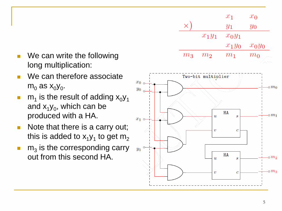
We can write the following
long multiplication:
We can therefore associate
m0 as x0y0.
m1 is the result of adding x0y1
and x1y0, which can be
produced with a HA.
Note that there is a carry out;
this is added to x1y1 to get m2
m3 is the corresponding carry
out from this second HA.
5
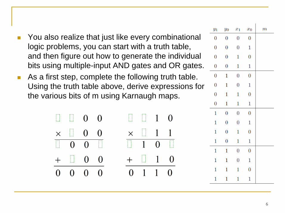
You also realize that just like every combinational
logic problems, you can start with a truth table,
and then figure out how to generate the individual
bits using multiple-input AND gates and OR gates.
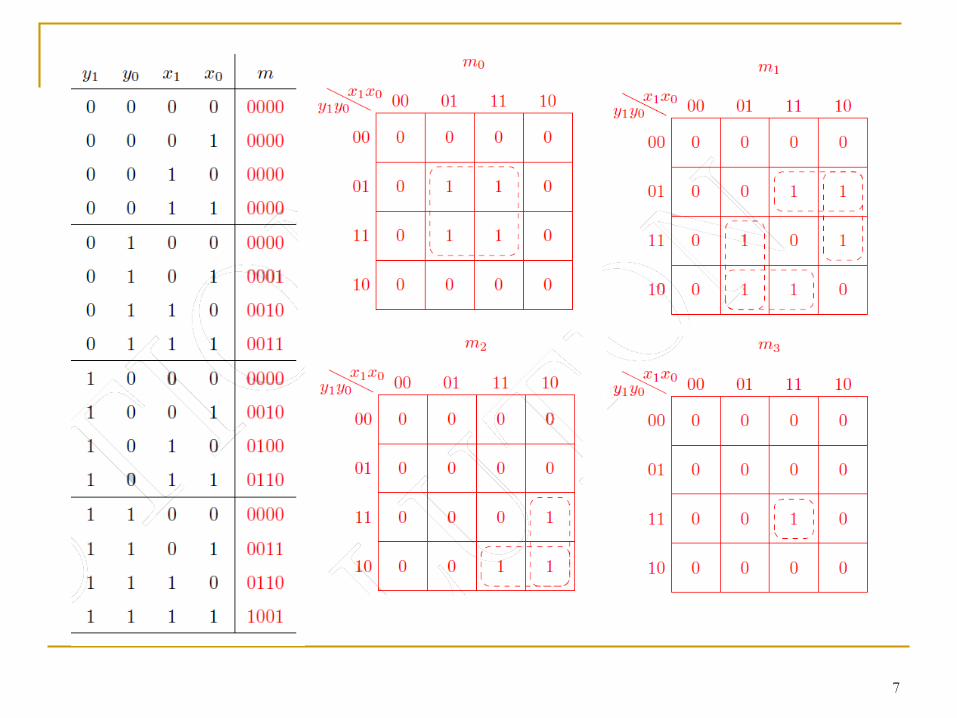
As a first step, complete the following truth table.
Using the truth table above, derive expressions for
the various bits of m using Karnaugh maps.
6
7
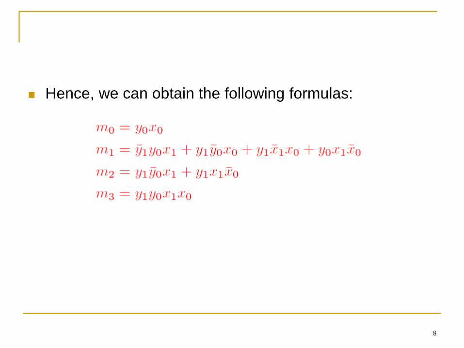
Hence, we can obtain the following formulas:
8
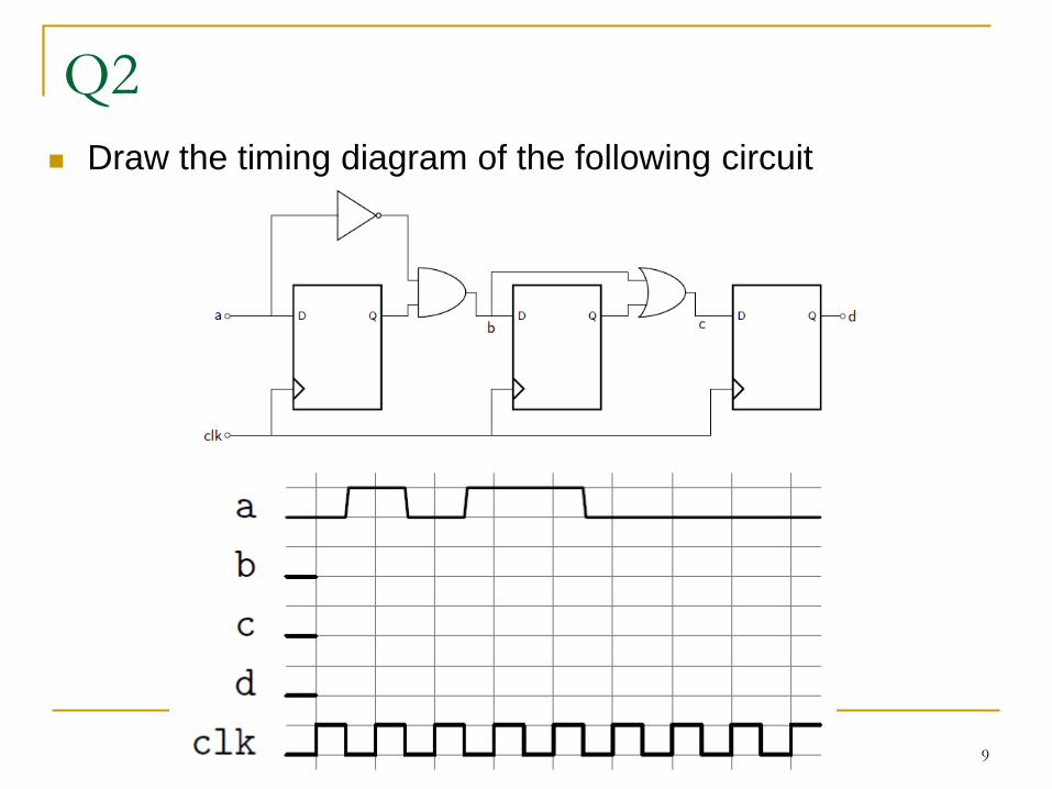
Q2
Draw the timing diagram of the following circuit
9
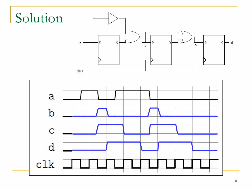
Solution
10
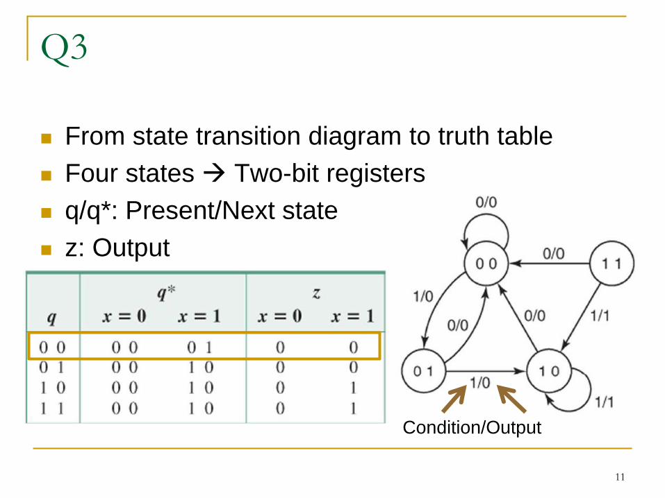
Q3
From state transition diagram to truth table
Four states Two-bit registers
q/q*: Present/Next state
z: Output
11
Condition/Output
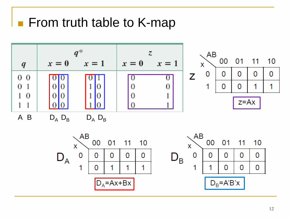
From truth table to K-map
12
DA DB DA DBA B
13
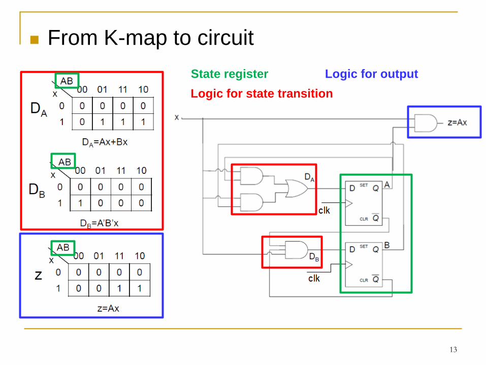
Logic for state transition
State register Logic for output
From K-map to circuit
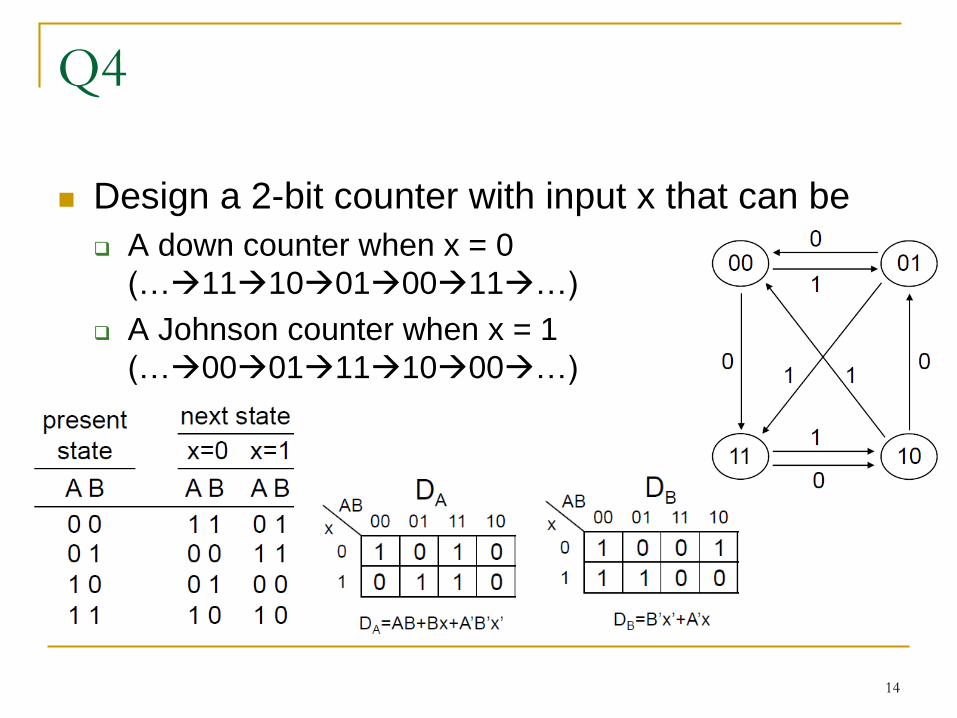
Q4
Design a 2-bit counter with input x that can be
A down counter when x = 0
(…1110010011…)
A Johnson counter when x = 1
(…0001111000…)
14
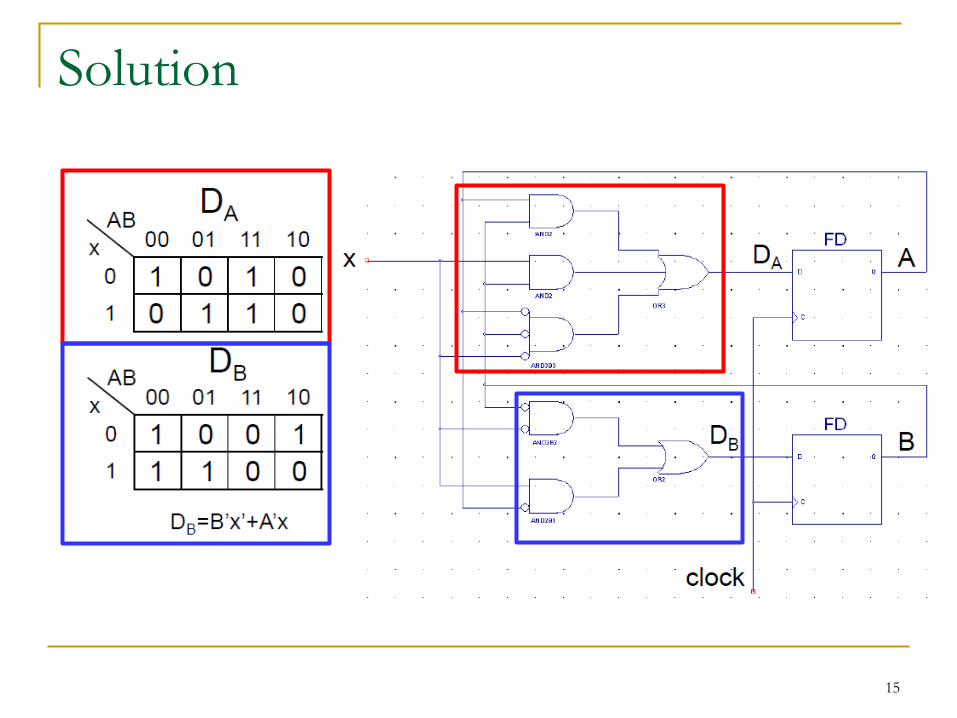
Solution
15
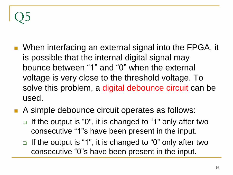
Q5
When interfacing an external signal into the FPGA, it
is possible that the internal digital signal may
bounce between “1” and “0” when the external
voltage is very close to the threshold voltage. To
solve this problem, a digital debounce circuit can be
used.
A simple debounce circuit operates as follows:
If the output is “0", it is changed to “1" only after two
consecutive “1"s have been present in the input.
If the output is “1", it is changed to “0” only after two
consecutive “0”s have been present in the input.
16
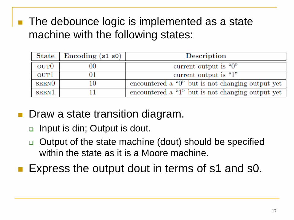
The debounce logic is implemented as a state
machine with the following states:
Draw a state transition diagram.
Input is din; Output is dout.
Output of the state machine (dout) should be specified
within the state as it is a Moore machine.
Express the output dout in terms of s1 and s0.
17

Solution
18
Next state of OUT 0
din=0 OUT0
din=1 SEEN1
Next state of SEEN1
din=0 OUT0
din=1 OUT1
dout s0 s1
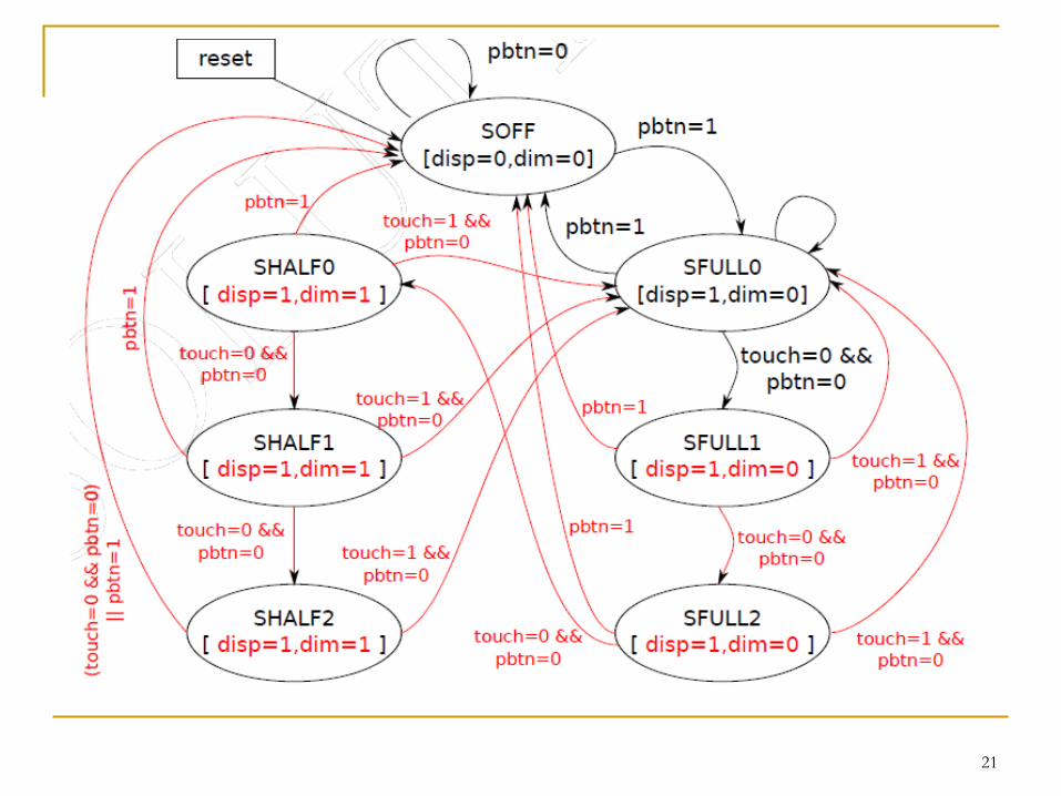
Q6
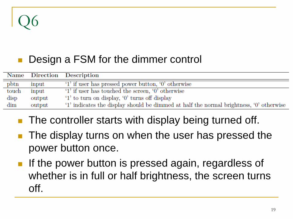
Design a FSM for the dimmer control
The controller starts with display being turned off.
The display turns on when the user has pressed the
power button once.
If the power button is pressed again, regardless of
whether is in full or half brightness, the screen turns
off.
19
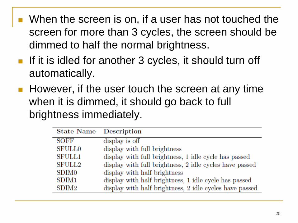
When the screen is on, if a user has not touched the
screen for more than 3 cycles, the screen should be
dimmed to half the normal brightness.
If it is idled for another 3 cycles, it should turn off
automatically.
However, if the user touch the screen at any time
when it is dimmed, it should go back to full
brightness immediately.
20
21
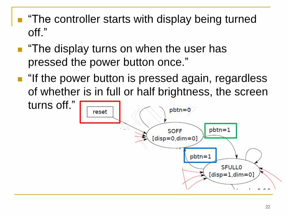
“The controller starts with display being turned
off.”
“The display turns on when the user has
pressed the power button once.”
“If the power button is pressed again, regardless
of whether is in full or half brightness, the screen
turns off.”
22
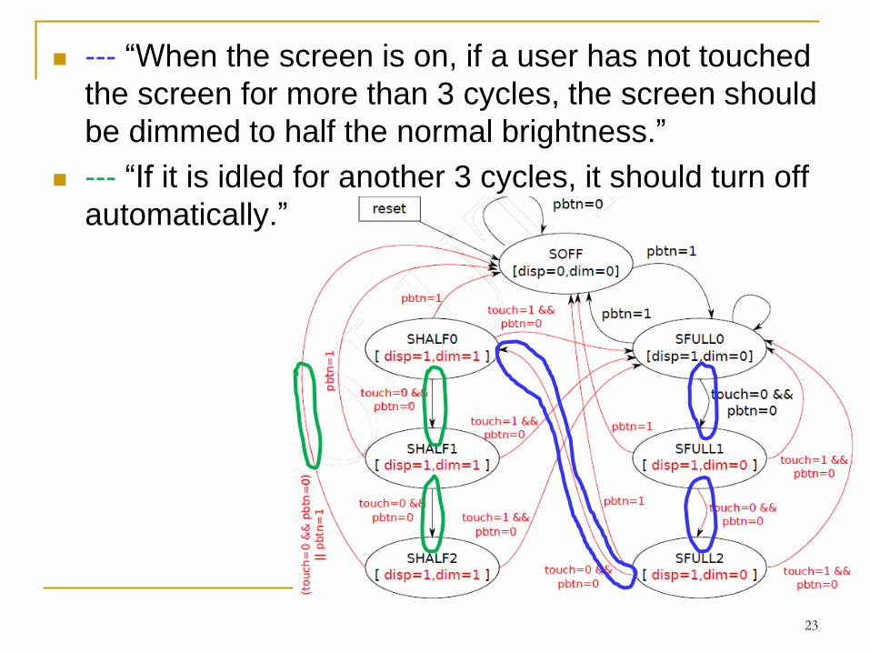
--- “When the screen is on, if a user has not touched
the screen for more than 3 cycles, the screen should
be dimmed to half the normal brightness.”
--- “If it is idled for another 3 cycles, it should turn off
automatically.”
23
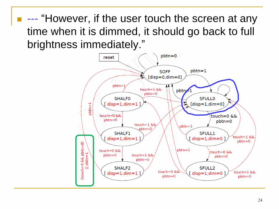
--- “However, if the user touch the screen at any
time when it is dimmed, it should go back to full
brightness immediately.”
24
Q7a
You decide to build one to help you make your
decision on bus choice (3B or 30X) every day You can only be in one of the 3 moods: HAPPY, NEUTRAL, SAD.
When you are SAD, you decide to get on whichever is the next
bus arriving at the bus stop.
When you are HAPPY, you wait at the bus stop until you can ride
on 30X.
When you are NEUTRAL, you will wait at the bus stop and not get
on a maximum of TWO 3Bs, before you give up and hop on
whichever bus arrives afterwards.
25
In addition, your mood changes as a result of which bus
you get on: When you are SAD, you become NEUTRAL after you get on a 30X, but
remain SAD if you get on a 3B.
When you are NEUTRAL, you become HAPPY after you get on a 30X,
but turn to SAD if you ride on a 3B.
When you are HAPPY, you always get back to NEUTRAL after riding the
bus.
26
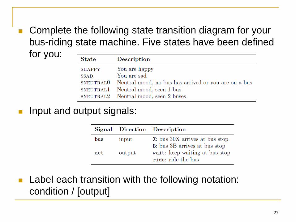
Complete the following state transition diagram for your
bus-riding state machine. Five states have been defined
for you:
Input and output signals:
Label each transition with the following notation:
condition / [output]
27

Solution
28
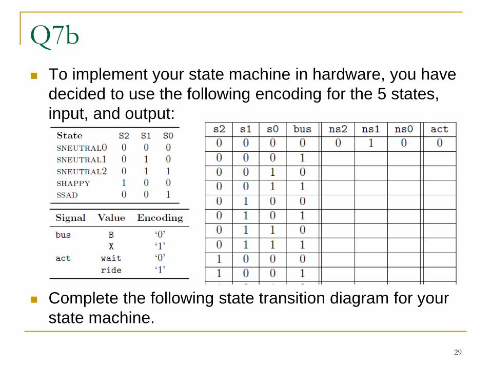
Q7b
To implement your state machine in hardware, you have
decided to use the following encoding for the 5 states,
input, and output:
Complete the following state transition diagram for your
state machine.
29
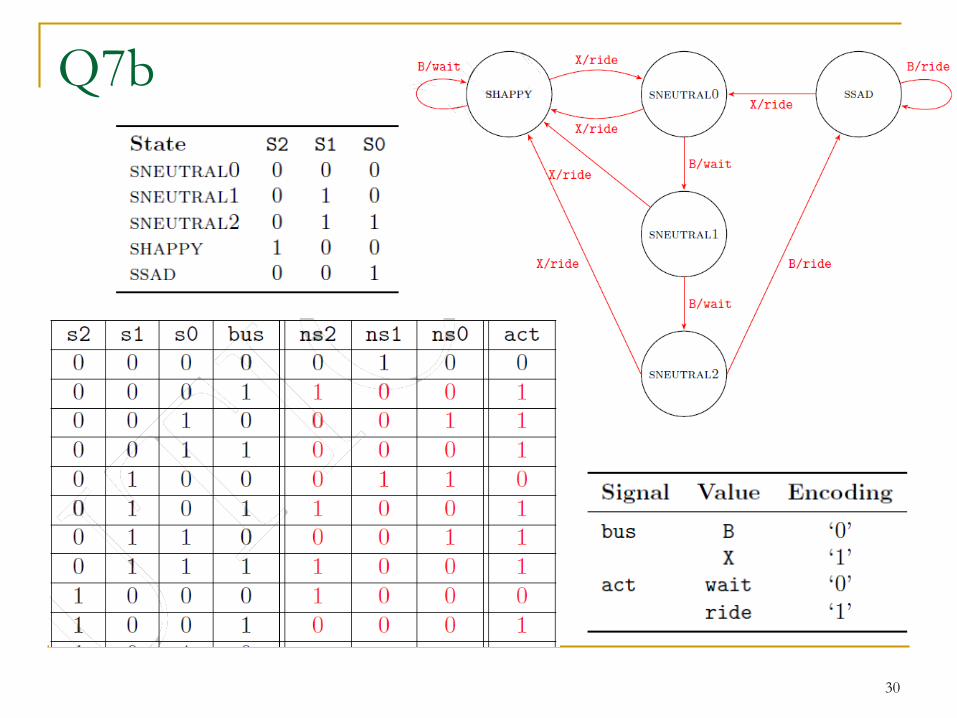
Q7b
30
(Appendix) Q8
The card reader tells the controller whether the
car is a member or a guest car.
Only one guest car is allowed per member at a
discount rate
Only when the guest follows out the member at the
exit (within the allotted time)
The second guest must pay the regular parking fees
Design a FSM for the card reader
31
Solution
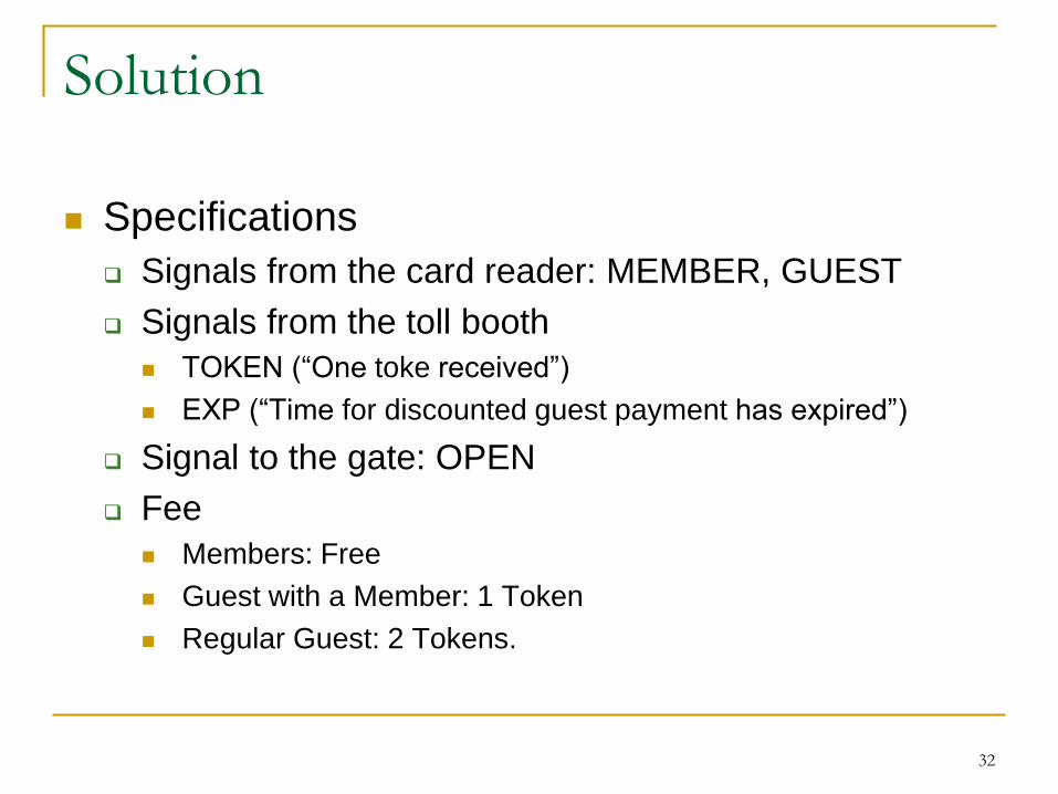
Specifications
Signals from the card reader: MEMBER, GUEST
Signals from the toll booth
TOKEN (“One toke received”)
EXP (“Time for discounted guest payment has expired”)
Signal to the gate: OPEN
Fee
Members: Free
Guest with a Member: 1 Token
Regular Guest: 2 Tokens.
32
Solution
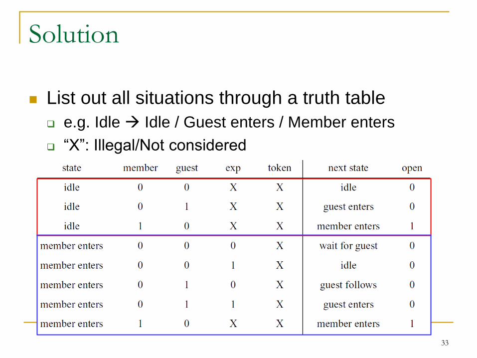
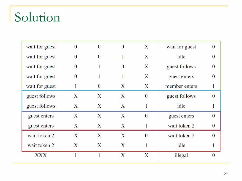
List out all situations through a truth table
e.g. Idle Idle / Guest enters / Member enters
“X”: Illegal/Not considered
33
Solution
34
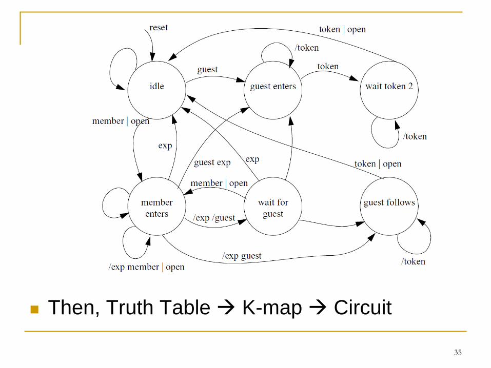
Then, Truth Table K-map Circuit
35
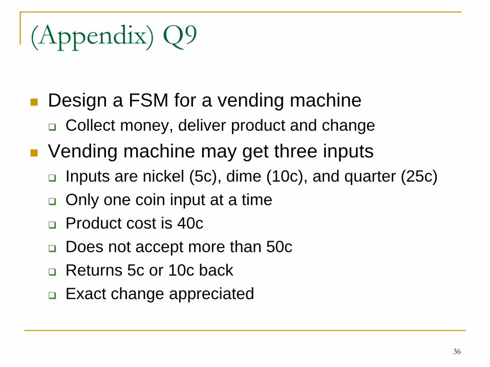
(Appendix) Q9
Design a FSM for a vending machine
Collect money, deliver product and change
Vending machine may get three inputs
Inputs are nickel (5c), dime (10c), and quarter (25c)
Only one coin input at a time
Product cost is 40c
Does not accept more than 50c
Returns 5c or 10c back
Exact change appreciated
36
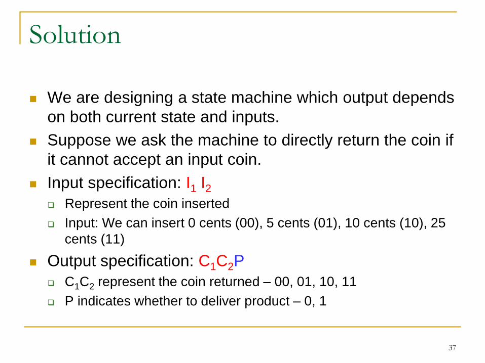
Solution
We are designing a state machine which output depends
on both current state and inputs.
Suppose we ask the machine to directly return the coin if
it cannot accept an input coin.
Input specification: I1 I2 Represent the coin inserted
Input: We can insert 0 cents (00), 5 cents (01), 10 cents (10), 25
cents (11)
Output specification: C1C2P
C1C2 represent the coin returned – 00, 01, 10, 11
P indicates whether to deliver product – 0, 1
37
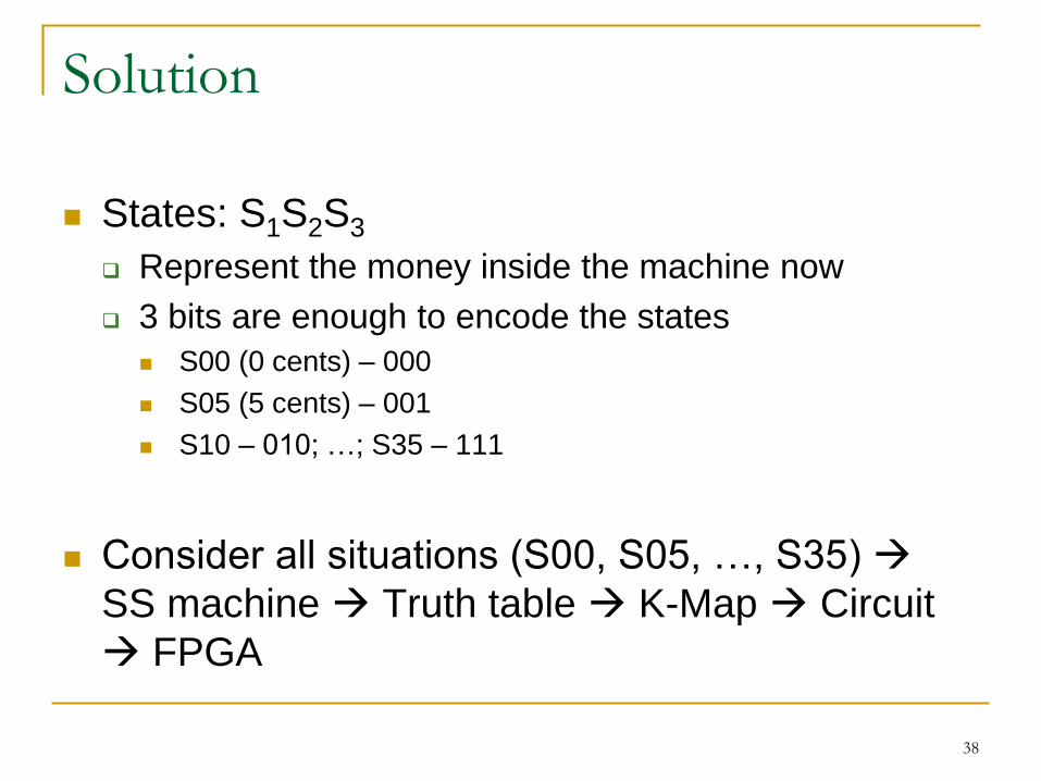
Solution
States: S1S2S3
Represent the money inside the machine now
3 bits are enough to encode the states
S00 (0 cents) – 000
S05 (5 cents) – 001
S10 – 010; …; S35 – 111
Consider all situations (S00, S05, …, S35)
SS machine Truth table K-Map Circuit
FPGA
38
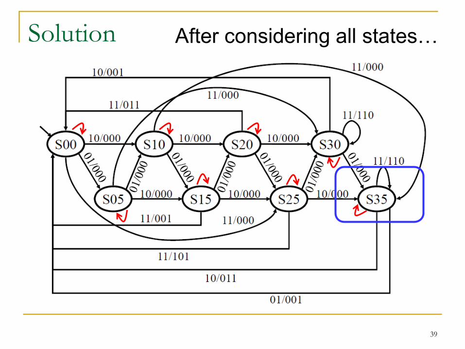
Solution
39
After considering all states…
Solution
40
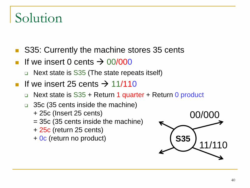
S35: Currently the machine stores 35 cents
If we insert 0 cents 00/000
Next state is S35 (The state repeats itself)
If we insert 25 cents 11/110
Next state is S35 + Return 1 quarter + Return 0 product
35c (35 cents inside the machine)
+ 25c (Insert 25 cents)
= 35c (35 cents inside the machine)
+ 25c (return 25 cents)
+ 0c (return no product)
00/000
11/110S35
Solution
41
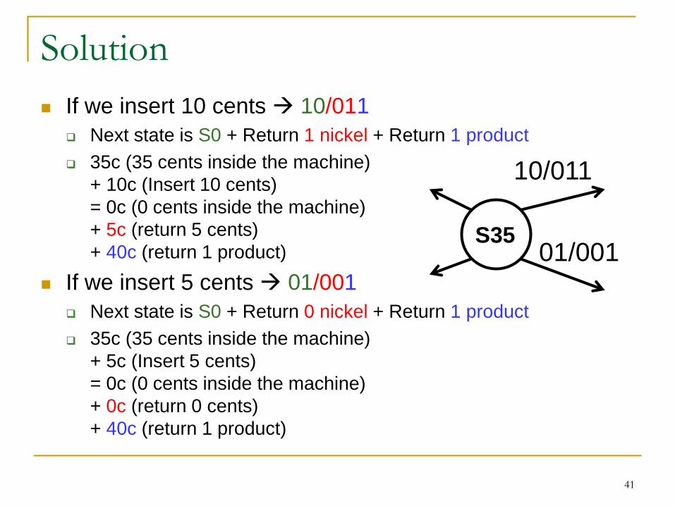
If we insert 10 cents 10/011
Next state is S0 + Return 1 nickel + Return 1 product
35c (35 cents inside the machine)
+ 10c (Insert 10 cents)
= 0c (0 cents inside the machine)
+ 5c (return 5 cents)
+ 40c (return 1 product)
If we insert 5 cents 01/001
Next state is S0 + Return 0 nickel + Return 1 product
35c (35 cents inside the machine)
+ 5c (Insert 5 cents)
= 0c (0 cents inside the machine)
+ 0c (return 0 cents)
+ 40c (return 1 product)
10/011
01/001S35
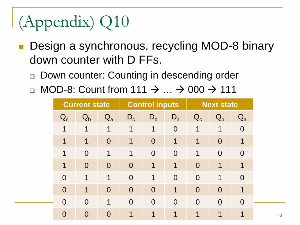
(Appendix) Q10
Design a synchronous, recycling MOD-8 binary
down counter with D FFs.
Down counter: Counting in descending order
MOD-8: Count from 111 … 000 111
42
Current state Control inputs Next state
Qc Qb Qa Dc Db Da Qc Qb Qa
1 1 1 1 1 0 1 1 0
1 1 0 1 0 1 1 0 1
1 0 1 1 0 0 1 0 0
1 0 0 0 1 1 0 1 1
0 1 1 0 1 0 0 1 0
0 1 0 0 0 1 0 0 1
0 0 1 0 0 0 0 0 0
0 0 0 1 1 1 1 1 1
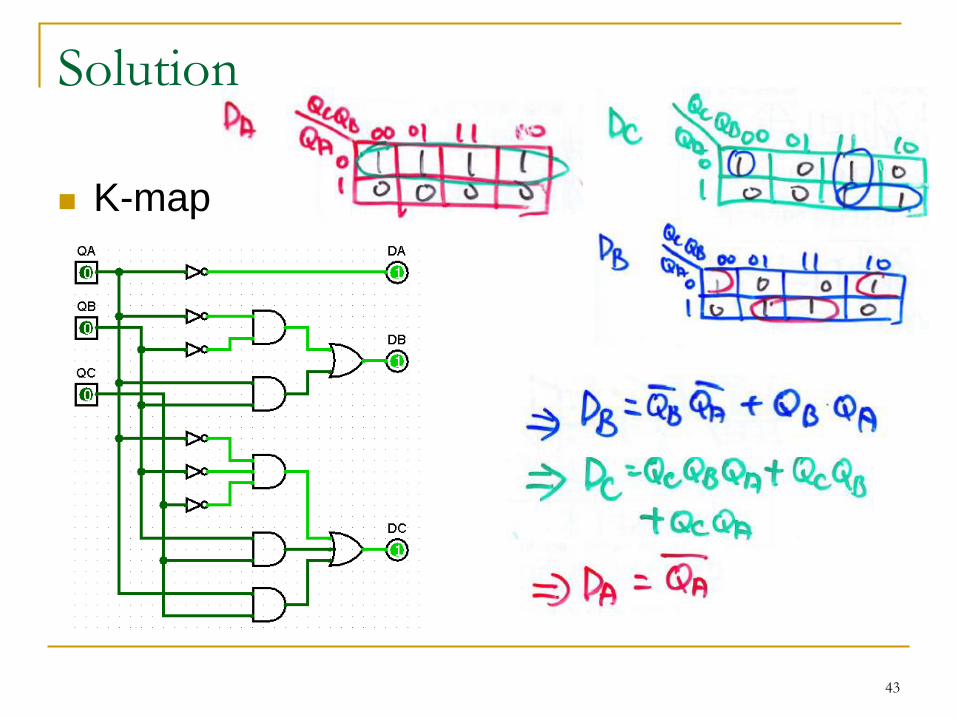
Solution
K-map
43
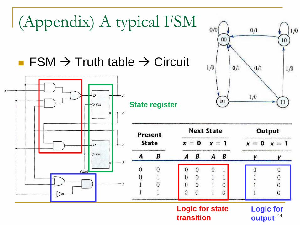
(Appendix) A typical FSM
44
FSM Truth table Circuit
Logic for
output
Logic for state
transition
State register
(Appendix) Steps in designing a state
machine Draw a state transition diagram
An initial state
Other states to keep track of various activities
Transitions
Generate a state transition table and a output table
Write state transition table and output table in binary
State assignment, i.e., the code used for each state
Derive canonical sum-of-product expressions
Draw the circuit
45