Embed Size (px)
Citation preview

Instructions & Parts
r_256998_313294_1b
US Patent Number 7,036,171Korean Patent 338185Australian Patent Number 152610
2004230905EP 1610904
r_256998_313294_10b
EnergyComplete™ Spray Gun
Manual No:
For use with EnergyComplete Air Infiltration Barrier with Flexible Seal Technology.Not for use in explosive atmospheres or with flammable materials.
Important Safety InstructionsRead all warnings and instructions in this manual. Save these instructions.
256998 EnergyComplete Spray Gun with Static Mixer Assembly
3500 psi (24.2 MPa, 242 bar) Maximum Fluid Working Pressure
80-130 psi (0.55-0.9 MPa, 5.5-9.1 bar) Air Inlet Pressure Range
200°F (94°C) Maximum Fluid Temperature
313294H

2 313294H
ContentsWarnings . . . . . . . . . . . . . . . . . . . . . . . . . . . . . . . . . 3Overall View . . . . . . . . . . . . . . . . . . . . . . . . . . . . . . . 5Keep A and B Components Separate . . . . . . . . . . 6Grounding . . . . . . . . . . . . . . . . . . . . . . . . . . . . . . . . 6Piston Safety Lock
(Trigger Lock) . . . . . . . . . . . . . . . . . . . . . . . . . . 7Loss of Air Pressure . . . . . . . . . . . . . . . . . . . . . . . . 7Setup . . . . . . . . . . . . . . . . . . . . . . . . . . . . . . . . . . . . . 8Shutdown . . . . . . . . . . . . . . . . . . . . . . . . . . . . . . . . . 9Pressure Relief Procedure . . . . . . . . . . . . . . . . . . 10Optional Configurations . . . . . . . . . . . . . . . . . . . . 11
Optional Fluid Manifold Position . . . . . . . . . . . . 11Optional Hose Position . . . . . . . . . . . . . . . . . . . 12
Maintenance . . . . . . . . . . . . . . . . . . . . . . . . . . . . . . 13Supplied Tool Kit . . . . . . . . . . . . . . . . . . . . . . . . 13Compatible Solvents . . . . . . . . . . . . . . . . . . . . . 13Keep Gun Clean . . . . . . . . . . . . . . . . . . . . . . . . 13As Needed . . . . . . . . . . . . . . . . . . . . . . . . . . . . 13Daily . . . . . . . . . . . . . . . . . . . . . . . . . . . . . . . . . 13Weekly to Monthly . . . . . . . . . . . . . . . . . . . . . . . 13Flush Gun . . . . . . . . . . . . . . . . . . . . . . . . . . . . . 14Clean Outside of Gun . . . . . . . . . . . . . . . . . . . . 14Clean Air Cap . . . . . . . . . . . . . . . . . . . . . . . . . . 14Clean Spray Tip . . . . . . . . . . . . . . . . . . . . . . . . 14Clean Muffler . . . . . . . . . . . . . . . . . . . . . . . . . . . 14Clean Fluid Manifold . . . . . . . . . . . . . . . . . . . . . 14Clean Mixer . . . . . . . . . . . . . . . . . . . . . . . . . . . . 14Clean Slip-Fit Polycarballoy Mix Module . . . . . . 15
Troubleshooting . . . . . . . . . . . . . . . . . . . . . . . . . . . 16Repair . . . . . . . . . . . . . . . . . . . . . . . . . . . . . . . . . . . 18
Tools Required . . . . . . . . . . . . . . . . . . . . . . . . . . 18Lubrication . . . . . . . . . . . . . . . . . . . . . . . . . . . . . 18Disassemble Front End . . . . . . . . . . . . . . . . . . . 18Reassemble Front End . . . . . . . . . . . . . . . . . . . 19Slip-Fit Polycarballoy Mix Module . . . . . . . . . . . 20Rear Rod Seal . . . . . . . . . . . . . . . . . . . . . . . . . . 21Adjust Rear Rod Seal . . . . . . . . . . . . . . . . . . . . 21Check Valves . . . . . . . . . . . . . . . . . . . . . . . . . . . 22Piston and Purge Rod . . . . . . . . . . . . . . . . . . . . 23Piston Safety Lock . . . . . . . . . . . . . . . . . . . . . . . 24Air Valve . . . . . . . . . . . . . . . . . . . . . . . . . . . . . . 24Static Mixer Assembly . . . . . . . . . . . . . . . . . . . . 25
Parts . . . . . . . . . . . . . . . . . . . . . . . . . . . . . . . . . . . . 26Accessories . . . . . . . . . . . . . . . . . . . . . . . . . . . . . . 28Gun Repair Kits . . . . . . . . . . . . . . . . . . . . . . . . . . . 28Check Valve Filter Screen Kits (10 per kit) . . . . . 28Technical Data . . . . . . . . . . . . . . . . . . . . . . . . . . . . 29Graco Standard Warranty . . . . . . . . . . . . . . . . . . . 30Graco Information . . . . . . . . . . . . . . . . . . . . . . . . . 30

Warnings
313294H 3
WarningsThe following warnings are for the setup, use, grounding, maintenance, and repair of this equipment. The exclama-tion point symbol alerts you to a general warning and the hazard symbol refers to procedure-specific risk. Refer back to these warnings. Additional, product-specific warnings may be found throughout the body of this manual where applicable.
WARNINGWARNINGWARNINGWARNINGSKIN INJECTION HAZARD High-pressure fluid from gun, hose leaks, or ruptured components will pierce skin. This may look like just a cut, but it is a serious injury that can result in amputation. Get immediate surgical treatment.• Do not point gun at anyone or at any part of the body.• Do not put your hand over the spray tip.• Do not stop or deflect leaks with your hand, body, glove, or rag.• Do not spray without tip guard.• Engage trigger lock when not spraying.• Follow Pressure Relief Procedure in this manual, when you stop spraying and before cleaning,
checking, or servicing equipment.
TOXIC FLUID OR FUMES HAZARD Toxic fluids or fumes can cause serious injury or death if splashed in the eyes or on skin, inhaled, or swallowed.• Read MSDS’s to know the specific hazards of the fluids you are using.• Store hazardous fluid in approved containers, and dispose of it according to applicable guidelines.• Always wear impervious gloves when spraying or cleaning equipment.
PERSONAL PROTECTIVE EQUIPMENT You must wear appropriate protective equipment when operating, servicing, or when in the operating area of the equipment to help protect you from serious injury, including eye injury, inhalation of toxic fumes, burns, and hearing loss. This equipment includes but is not limited to:• Protective eyewear • Clothing and respirator as recommended by the fluid and solvent manufacturer• Gloves• Hearing protection
BURN HAZARD Equipment surfaces and fluid that’s heated can become very hot during operation. To avoid severe burns, do not touch hot fluid or equipment. Wait until equipment/fluid has cooled completely.

Warnings
4 313294H
WARNINGWARNINGWARNINGWARNINGFIRE AND EXPLOSION HAZARD Flammable fumes, such as solvent and paint fumes, in work area can ignite or explode. To help prevent fire and explosion:• Use equipment only in well ventilated area.• Eliminate all ignition sources; such as pilot lights, cigarettes, portable electric lamps, and plastic drop
cloths (potential static arc). • Keep work area free of debris, including solvent, rags and gasoline.• Do not plug or unplug power cords, or turn power or light switches on or off when flammable fumes
are present.• Ground all equipment in the work area. See Grounding instructions.• Use only grounded hoses.• Hold gun firmly to side of grounded pail when triggering into pail.• If there is static sparking or you feel a shock, stop operation immediately. Do not use equipment
until you identify and correct the problem.• Keep a working fire extinguisher in the work area.
EQUIPMENT MISUSE HAZARD Misuse can cause death or serious injury.• Do not operate the unit when fatigued or under the influence of drugs or alcohol.• Do not exceed the maximum working pressure or temperature rating of the lowest rated system
component. See Technical Data in all equipment manuals.• Use fluids and solvents that are compatible with equipment wetted parts. See Technical Data in all
equipment manuals. Read fluid and solvent manufacturer’s warnings. For complete information about your material, request MSDS forms from distributor or retailer.
• Check equipment daily. Repair or replace worn or damaged parts immediately with genuine manu-facturer’s replacement parts only.
• Do not alter or modify equipment.• Use equipment only for its intended purpose. Call your distributor for information.• Route hoses and cables away from traffic areas, sharp edges, moving parts, and hot surfaces.• Do not kink or over bend hoses or use hoses to pull equipment.• Keep children and animals away from work area.• Comply with all applicable safety regulations.
PRESSURIZED EQUIPMENT HAZARD Fluid from the gun/dispense valve, leaks, or ruptured components can splash in the eyes or on skin and cause serious injury.• Follow Pressure Relief Procedure in this manual, when you stop spraying and before cleaning,
checking, or servicing equipment. • Tighten all fluid connections before operating the equipment.• Check hoses, tubes, and couplings daily. Replace worn or damaged parts immediately.
PRESSURIZED ALUMINUM PARTS HAZARD Do not use 1,1,1-trichloroethane, methylene chloride, other halogenated hydrocarbon solvents or fluids containing such solvents in pressurized aluminum equipment. Such use can cause serious chemical reaction and equipment rupture, and result in death, serious injury, and property damage.

Overall View
313294H 5
Overall View
Key:A A Side Fluid Valve (white)B B Side Fluid Valve (red)C Air CapD Air Line Quick CouplerE MufflerF Fluid HousingG Gun Fluid ManifoldH HandleJ Optional Air InletK Cleanoff Air ValveL Piston Safety LockM Static Mixer AdapterN Optional Fluid Inlets (A Side Shown)P Lock RingR Fluid Inlet Swivels (A Side Shown)S TriggerT Gun Air Whip HoseU Air ValveV Static MixerW RAC tip
r_256998_313294_7b
A
W
BG
S
JE
H
N
R
U
D
T
L
PK
F
C
M
V

Keep A and B Components Separate
6 313294H
Keep A and B Components Separate
Grounding
Check your local electrical code and proportioner man-ual 313221 for detailed grounding instructions.
NOTICE• To prevent cross-contamination of the gun’s wet-
ted parts, do not interchange A component (white fluid) and B component (red fluid) parts. The gun is shipped with the A side on the left. The fluid manifold, fluid housing, side seal car-tridge, check valve cartridge, and mix chamber are marked on the A side.

Piston Safety Lock (Trigger Lock)
313294H 7
Piston Safety Lock(Trigger Lock)Engage piston safety lock whenever you stop spray-ing, to avoid accidental triggering.
To engage piston safety lock: push knob in and turn clockwise. If engaged, gun will not actuate.
To disengage piston safety lock: push knob in and turn counterclockwise until it pops out. There will be a gap between knob and gun body.
Loss of Air PressureIn event of loss of air pressure while gun is triggered, gun will continue to spray. To shut off gun, do one of the following:
• Push hard or hit end of safety lock, to engage piston safety lock.
• Close fluid valves A and B.
FIG. 1
FIG. 2
Engaged
TI3850A
TI3849A
Disengaged
TI5003A
A
B
r_256998_313294_1b

Setup
8 313294H
Setup1. Assemble static mixer housing (60) and mix element
(62) on front end of gun.
2. Assemble RAC tip and guard (64, 65) assembly.
a. Use end of tip (65) to press gasket and seat into guard (64), with curve matching tip bore (T).
b. Insert RAC tip (65) into tip bore (T).
c. Screw guard (64) onto static mixer housing (60) with wrench to properly seat gasket.
d. Loosen guard (64) with wrench and tighten hand tight.
3. Close fluid valves A and B.
4. Connect A (white) and B (red) fluid hoses to fluid manifold.
5. Engage piston safety lock, page 7.
6. Connect gun air whip hose and air valve to main air hose. Attach fluid manifold (M) to gun.
64
6265
seatgasket
60
r_256998_313294_2b
65
seatgasket T
64
TI2411A
A (White)
B (Red)
TI2417A
TI3850A
Engaged
r_256998_313294_1b
M

Shutdown
313294H 9
7. Connect quick coupler (D). Turn on air. Open air valve connected to whip hose. Air valve (K) should be screwed tight. There is no clean off air to adjust on the mechanical purge gun.
NOTE:
To use optional air inlet, see Optional Hose Position on page 12.
8. Adjust Purge Rod Position, see page 23.
9. Turn on proportioner.
10. Open B (red fluid) fluid valve (about three half turns). Then open A (white fluid) fluid valve.
11. Disengage piston safety lock, page 7.
12. Turn RAC tip (65) to spray position.
13. Test spray onto cardboard. Adjust pressure and temperature to get desired results.
14. Apply layer of lubricant over front of gun and lock ring, or use gun cover to prevent overspray buildup and ease disassembly. See Accessories on page 28 to order lubricant and gun cover.
15. Gun is ready to spray.
Shutdown1. Follow Pressure Relief Procedure, page 10.
2. Flush Gun, page 14.
r_256998_313294_1b
D
K
B fluid valveA fluid valve
r_256998_313294_1b
TI3849A
Disengaged
NOTICEAir supply is required for gun actuation. Do not dis-connect gun air supply until fluid pressure is relieved, page 10.
65exp1008A

Pressure Relief Procedure
10 313294H
Pressure Relief Procedure
1. Engage piston safety lock, page 7.
2. Close fluid valves A and B. Leave air valve con-nected to whip hose open.
3. Disengage piston safety lock, page 7.
4. Ensure RAC tip (65) is in spray position.
5. Trigger gun onto cardboard or into waste container to relieve pressure.
If you suspect spray tip or hose is clogged or that pres-sure has not been fully relieved after following the steps above, VERY SLOWLY loosen tip guard retaining nut or hose end coupling to relieve pressure gradually, then loosen completely. Clear hose or tip obstruction.
6. Engage piston safety lock, page 7.
Relieve pressure before cleaning or repairing gun.
NOTICEAir supply is required for gun actuation. Do not dis-connect gun air supply until fluid pressure is relieved.
TI3850A
Engaged
A
B
r_256998_313294_1b
TI3849A
Disengaged
Fluid in the hose and proportioner is still under pres-sure. Follow the Pressure Relief Procedure in the pro-portioner manual.
To relieve pressure in the hose after the gun is removed, place the fluid manifold over containers, fac-ing away from you. Very carefully open the fluid valves. Under high pressure, fluid will spray sideways from the fluid ports.
65 exp1008A
TI3850A
Engaged
TI2484A

Optional Configurations
313294H 11
Optional Configurations
Optional Fluid Manifold PositionFluid manifold is mounted to bottom of gun, with A side on left, viewed from operator’s position at back of gun. If desired, manifold may be moved to top of gun. Doing this will reposition A side parts (fluid inlet, check valve, and fluid housing A side) to right.
1. Follow Pressure Relief Procedure, page 10.
2. Disconnect air hose from quick disconnect (D) and remove fluid manifold (G).
3. Unscrew lock ring (P) until front end of gun is loose.
4. Rotate fluid housing (F) 180° and retighten lock ring very securely.
5. Attach fluid manifold. Connect air. Return gun to service.
NOTICETo prevent cross-contamination of gun’s wetted parts, do not interchange A component (white) and B component (red) parts.
r_256998_313294_1b
D
G
P
F

Optional Configurations
12 313294H
Optional Hose PositionFluid inlet swivels and air quick disconnect fitting point to rear. If desired, these positions can be changed so hoses travel downward.
Fluid Hoses
1. Follow Pressure Relief Procedure, page 10. Also relieve system pressure and flush both fluid hoses, see proportioner manual.
2. Disconnect air hose from quick disconnect (D) and remove fluid manifold (G).
3. Disconnect fluid hoses from inlet swivels (A, B). Remove swivels. Remove plugs from optional inlets (N).
4. Apply thread sealant to plugs (42c), elbows (AA), and male threads of swivels (42e, 42f). Install elbows (16) in optional inlets (N), facing down. Install swivels (A, B) in elbows. Be sure to install A swivel (larger) in A side. Install plugs (42c) where swivels had been. Torque all parts to 235-245 in-lb (26.6-27.7 N•m).
5. Connect appropriate hoses to A and B swivels.
Air Hose
1. Remove quick disconnect fitting (D) and plug (J). Reverse positions. Apply thread sealant and torque to 125-135 in-lb (14-15 N•m).
2. Attach fluid manifold (G). Connect air. Return gun to service.
NOTICETo prevent cross-contamination of gun’s wetted parts, do not interchange A component (white) and B component (red) parts.
r_256998_313294_1b
D
G
A (White)
B (Red)
TI2417A
N
42c
AA42e
N42f
r_256998_313294_8b
J
r_256998_313294_1b
D
G

Maintenance
313294H 13
Maintenance
Supplied Tool Kit• Hex Nut Driver; 5/16
• Screwdriver; 1/8 blade
• #77 drill bit
• 117661 Pin Vise; dual reversible chucks
Compatible SolventsUse the following solvents for cleaning and flushing A and B fluid.
Keep Gun CleanKeep gun clean with accessory gun cover 244915.
Applying a light coat of lubricant will make cleaning eas-ier. Lubricate threads and outside of lock ring (11) to ease disassembly. Use Fusion Gun Lubricant (29).
As Needed1. Clean Outside of Gun, page 14.
2. Clean Air Cap, page 14.
3. Clean Muffler, page 14.
4. Clean Fluid Manifold, page 14.
5. Clean Slip-Fit Polycarballoy Mix Module, page 15.
Daily1. Follow Shutdown, page 9.
2. Clean Check Valves, page 22. Check o-rings and screens.
Weekly to MonthlyCheck that piston safety lock threaded connection is tight, page 24.A and B Fluid Compatible Solvent
A side (white) Water
B side (red) Owens Corning B-Side Cleaner
TI3864a
Reversible
Reversible

Maintenance
14 313294H
Flush Gun
If it is necessary to flush the mix module, use following procedure.
1. Follow Pressure Relief Procedure, page 10.
2. Flush with a compatible solvent.
3. Flush into a grounded metal pail, holding a metal part of fluid manifold firmly to side of pail. Use the lowest possible fluid pressure when flushing.
Clean Outside of GunWipe off outside of gun with compatible solvent.
Clean Air CapSoak air cap in compatible solvent. If necessary, clean gently with stiff brush.
Clean Spray TipClean spray tip with a solvent soaked brush. Clean front of tip frequently to reduce fluid build up. Clean tip and tip guard at the end of each work day.
Clean MufflerA partially plugged muffler (51) will slow gun actuation. Remove and clean muffler with compatible solvent.
Clean Fluid ManifoldClean fluid manifold sealing faces with compatible sol-vent and a brush whenever removed from gun. Be sure to clean the two fluid ports (AB) in the top mating sur-face. Do not damage the flat sealing surfaces. Cover with Fusion Lubricant (29) if left exposed, to seal out moisture.
Clean MixerThe center mix element can be pressed out, front to back, even if fully cured. The mix element can then be cleaned with a wire brush.
AB
TI2411-1

Maintenance
313294H 15
Clean Slip-Fit Polycarballoy Mix Module1. Follow Pressure Relief Procedure, page 10.
2. Flush Gun, page 14.
3. Remove mix module, page 20.
4. See FIG. 3 and FIG. 4. Clean mix module impinge-ment ports (IP) with appropriate size drill (supplied).
NOTE:
• Component B (red) impingement ports, at rear of mix module, are angled toward front of gun. See FIG. 4.
• When cleaning do not scratch the sealing edges and ports.
5. Reassemble, page 20.
NOTICETo avoid damaging mix module, do not force drill bits when cleaning impingement ports. Some ports are offset or angled.
FIG. 3: Cleaning Component A (White) Ports
TI3863a
FIG. 4: Cleaning Component B (Red) Ports
TI3862a

Troubleshooting
16 313294H
Troubleshooting1. Follow Pressure Relief Procedure, page 10,
before checking or repairing gun.
2. Check all possible problems and causes before dis-assembling gun.
NOTICETo prevent cross-contamination of the gun’s wetted parts, do not interchange A component (white) and B component (red) parts.
PROBLEM CAUSE SOLUTION
Gun does not fully actuate when trig-gered.
Piston safety lock engaged. Disengage piston safety lock, page 7.
Plugged muffler (51). Clean, page 14.
Damaged air valve o-rings (24). Replace, page 15.
Fluid does not spray when gun is fully actuated.
Closed fluid valves (42b). Open.
Plugged impingement ports. Clean, page 15.
Plugged check valves (36). Clean, page 22.
Gun actuates slowly or with delayed action.
Plugged muffler (51). Clean, page 14.
Damaged piston o-rings (45, 48). Replace, page 23.
Dirty air valve, or damaged o-rings (37d).
Clean air valve or replace o-rings, page 24.
Mix module nut (54) too tight. Loosen nut, then retighten, page 20.
Loose lock ring (37b). Tighten, use tool if necessary.
Purge rod will not actuate. No air pressure. Connect air supply.
Low air pressure. Set air pressure above 80 psi (0.56 MPa, 5.6 bar).
Buildup on purge rod (34). Clean purge rod.
Pressure imbalance. Plugged impingement ports. Clean, page 15. Reinstall mix mod-ule, page 20.
Plugged check valves (39). Clean, page 22.
Viscosities not equal. Adjust temperature to compensate.

Troubleshooting
313294H 17
Fluid does not shut off when fluid valves are closed.
Damaged fluid valves (42b). Replace.
Air leakage around fluid housing. Damaged or missing o-ring (49). Replace.
Air leakage from piston safety lock. Damaged or missing o-rings (47). Replace, page 23.
Burst of air from muffler when gun is triggered.
Normal. No action required.
Steady air leakage from muffler. Damaged air valve o-rings (37d). Replace, page 24.
Damaged piston o-rings (45, 48). Replace, page 23.
Air leakage from front air valve. Damaged air valve o-rings (37d). Replace, page 24.
Component B (resin) leak from fluid housing.
Worn rear rod seal. Adjust Rear Rod Seal, page 21.
Cross Contamination of A and B components.
Worn out mix module. Replace.
Sealing surface OD not clean. Clean sealing surface on fluid hous-ing.
Air leakage from holes on solvent purge assembly.
Cleanoff air valve open. Close cleanoff air valve tightly. Clea-noff air valve should never be open when using solvent purge gun.
Fluid leakage from holes on solvent purge assembly.
Mix module nut is only handtight. Tighten mix module nut 1/12 with wrench.
PROBLEM CAUSE SOLUTION
Repair
18 313294H
Repair
Tools RequiredTools needed for complete gun repair:
• adjustable wrench• flat head screwdriver (included)• channel-lock pliers (2 pair)• 5/16 hex nut driver (included)• o-ring pick• medium-strength Loctite®• solvent or alcohol
LubricationLiberally lubricate all o-rings, seals, and threads with Fusion Gun Lubricant (29). Lubricate threads and out-side of lock ring (11).
Disassemble Front End1. Follow Pressure Relief Procedure, page 10.
2. Flush Gun, page 14.
3. Remove RAC guard and tip (64, 65), static mixer housing (60), mixer element (62) from fluid head (59).
4. Loosen air cap (61) and remove from gun.
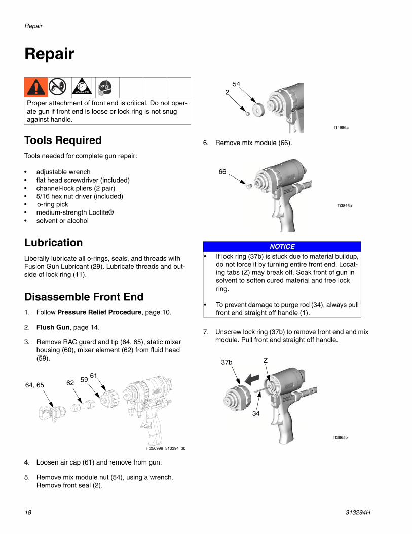
5. Remove mix module nut (54), using a wrench. Remove front seal (2).
6. Remove mix module (66).
7. Unscrew lock ring (37b) to remove front end and mix module. Pull front end straight off handle.
Proper attachment of front end is critical. Do not oper-ate gun if front end is loose or lock ring is not snug against handle.
64, 65 6261
r_256998_313294_3b
59
NOTICE• If lock ring (37b) is stuck due to material buildup,
do not force it by turning entire front end. Locat-ing tabs (Z) may break off. Soak front of gun in solvent to soften cured material and free lock ring.
• To prevent damage to purge rod (34), always pull front end straight off handle (1).
254
TI4986a
Ti3846a
66
TI3865b
37b
34
Z

Repair
313294H 19
Reassemble Front End1. Check that o-rings (37e, 49) are in position. Liberally
lubricate o-rings, threads of lock ring (37b) and han-dle (1), and outside of lock ring.
2. Orient front end as required for desired fluid mani-fold mounting (bottom mounting shown). Align slots (Y) to engage tabs (Z).
3. Carefully slide front end straight onto purge rod (34). Screw lock ring (37b) onto handle (1) as far as pos-sible by hand. Push on front end to ensure it is prop-erly seated. Continue screwing lock ring onto handle
until tightened very securely. When properly assem-bled, lock ring is snug against handle.
4. Push mix module (66) onto rod (34) as far as possi-ble.
5. Lubricate all threads and reassemble mix module nut (54) fingertight. Tighten additional 1/12 turn with wrench. Install front seal (2) on rod (34).
6. Reinstall air cap (61) and fluid head (59). Lubricate all threads. Install mixer element (62), static mixer housing (60,) and RAC tip and guard (64,65). Tighten with wrench.
NOTICETo prevent damage to purge rod (34), always slide front end straight onto purge rod.
TI3871a
37b37e
TI3873a
TI3871a
Z
Y
49NOTICE
Do not overtighten mix module nut (54). Overtighten-ing can deform impingement holes and cause slow gun actuation.
TI3866a
37b1
34
37a
66
37 TI3845a
34
1/12 Turn
TI4986a
2
54
34
64, 65 6261
r_256998_313294_3b
59

Repair
20 313294H
Slip-Fit Polycarballoy Mix Module1. Follow Pressure Relief Procedure, page 10.
2. Flush Gun, page 14.
3. Remove fluid manifold (G). Leave air connected.
4. Unscrew air cap (61) to remove RAC tip and guard (64, 65), static mixer housing (60), mixer element (62) and fluid head (59) from gun.
5. Remove mix module nut (54), using a wrench. Remove front seal (2).
6. Disengage piston safety lock (L), page 7. Trigger and detrigger gun once to release mix module (66) from fluid housing (37). Remove mix module. Engage piston safety lock.
NOTE:
If mix module (66) does not protrude from fluid housing (37), slightly loosen then retighten lock ring (37b), to allow gripping of edge for removal.
7. Push mix module (66) onto rod (34) as far as possi-ble.
8. Lubricate all threads and reassemble mix module nut (54) fingertight. Tighten additional 1/12 turn with wrench. Install front seal (2) on rod (34).
r_256998_313294_1bG
64, 65 60, 62 6159
r_256998_313294_4b
TI3843a
254
NOTICEDo not overtighten mix module nut (54). Overtighten-ing can deform impingement holes and cause slow gun actuation.
66
37
TI3845a
37b L
66
37
TI3845a
34
TI4986a
1/12 Turn
2
54

Repair
313294H 21
9. Reinstall air cap (61) and fluid head (59). Lubricate all threads. Install static mixer housing (60), mixer element (62), and RAC tip and guard (64, 65). Tighten with wrench.
10. Attach fluid manifold. Return gun to service.
Rear Rod Seal1. Follow Pressure Relief Procedure, page 10.
2. Flush Gun, page 14.
3. Remove fluid manifold (G). Leave air connected.
4. Disassemble Front End, page 18.
5. Remove rear rod seal nut (37g) with nut driver (13).
6. Push out rear seal (37h) with screwdriver (27).
7. Reassemble new rear seal (37h) in rear rod seal nut (37g). Lubricate threads and install in fluid housing (37a) with nut driver.
8. Reassemble Front End, page 19.
9. Attach fluid manifold. Connect air. Return gun to service.
Adjust Rear Rod Seal1. Follow Pressure Relief Procedure, page 10.
2. Flush Gun, page 14.
3. Remove fluid manifold (G). Leave air connected.
4. Disassemble Front End, page 18.
5. Assemble fluid housing (37a) backwards onto lubri-cated purge rod (34). Adjust rear rod seal nut (37g) with nut driver until drag is felt when sliding on rod.
6. Remove fluid housing (37a) from rod (34).
7. Reassemble Front End, page 19.
8. Attach fluid manifold. Return gun to service.
64, 65 60, 62 6159 r_256998_313294_4b
r_256998_313294_1bG
37g
TI3869a
13
27
37h
TI3872a
r_256998_313294_1bG
37a 34
23
TI3831a

Repair
22 313294H
Check Valves
NOTE:
Before disassembling, press on ball (36c) to test check valve for proper movement and spring action.
1. Follow Pressure Relief Procedure, page 10.
2. Flush Gun, page 14.
3. Disconnect air hose from quick disconnect (D) and remove fluid manifold (G). Clean and inspect check valve mating surfaces and fluid ports.
4. Pry out check valves (39) at notch.
5. Slide filter (39d) off. Clean and inspect parts. Thor-oughly inspect o-rings (39f, 39g). If necessary, remove screw (39b) and disassemble check valve.
6. Reassemble check valves. Screw (39b) should be flush (within 1/16 in. or 1.5 mm) of housing (39a) surface. Liberally lubricate o-rings (39f, 39g) and carefully reinstall in fluid housing.
7. Attach fluid manifold. Connect air. Return gun to service.
NOTICEDamaged check valve o-rings (39f, 39g) may result in external leakage. Replace o-rings if any damage is seen.
NOTICETo prevent cross-contamination of the check valves, do not interchange A component and B component parts. The A component check valve is marked with an A.
D
r_256998_313294_1bG
39b
39
B
A
39e39c
39d39g
39a39f TI4987a

Repair
313294H 23
Piston and Purge Rod1. Follow Pressure Relief Procedure, page 10.
2. Flush Gun, page 14.
3. Disconnect air hose from quick disconnect (D) and remove fluid manifold (G).
4. Disassemble Front End, page 18.
5. Unscrew purge rod stop (33d) to remove piston safety lock assembly. Inspect o-rings (33f, 33g) in place.
6. Pull purge rod to remove piston (40). Inspect piston o-ring (45) and shaft o-ring (48).
7. Inspect purge rod (34) for scratches or damage. Unscrew rod from piston with nut driver. Inspect o-ring (33g). Liberally lubricate with Fusion Gun Lubricant. To reassemble, thread purge rod (34) into piston (40) until rod stops.
8. Liberally lubricate piston o-rings. Reinstall piston. Shaft is keyed for proper assembly. Push firmly to seat piston. Rotate piston/purge rod assembly clockwise with nut driver until piston is fully seated.
9. Install piston safety lock assembly until bottomed out.
10. Reassemble Front End, page 19.
11. Attach fluid manifold. Connect air. Return gun to service.
D
r_256998_313294_1bG
33d
33f
TI3847a
33g
4548
40
TI4988a
33g34
TI3848a16
40
48
TI4988a
TI3847a

Repair
24 313294H
Piston Safety Lock1. Follow Pressure Relief Procedure, page 10.
2. Flush Gun, page 14.
3. Disconnect air hose from quick disconnect (D) and remove fluid manifold (G).
4. Unscrew cap (33a) from stop (33d), using two pair of channel-lock pliers. Inspect spring (33e), safety actuator (33b), bushing (33c), and o-rings (33f, 33g).
5. Lubricate o-rings (33f, 33g) and piston safety lock actuator (33b), and reassemble. Use Fusion Gun Lubricant (29). Clean threads with solvent or alco-hol. Apply medium-strength Loctite® or equivalent to threads on stop (33d) and cap (33a), and reas-semble.
6. Attach fluid manifold. Connect air. Return gun to service.
Air Valve1. Follow Pressure Relief Procedure, page 10.
2. Flush Gun, page 14.
3. Disconnect air hose from quick disconnect (D) and remove fluid manifold (G).
4. Unscrew air valve plug (32) and remove spring (55). Using small screwdriver (27), push spool (56) out from front. Inspect o-rings (53).
5. Liberally lubricate o-rings and reassemble. Use Fusion Gun Lubricant (29). Torque plug (32) to 125-135 in-lb (14-15 N•m).
6. Attach fluid manifold. Connect air. Return gun to service.
D
r_256998_313294_1bG
33a
33d
33e
33b, 33c
TI3835b
33f33g
D
r_256998_313294_1bG
5356
55 32
TI4990a

Repair
313294H 25
Static Mixer Assembly1. Follow Pressure Relief Procedure, page 10.
2. Flush Gun, page 14.
3. Disconnect air hose from fitting (D) and remove fluid manifold (G).
4. Disassemble RAC tip, guard (64, 65) and static mixer housing (60) from fluid head (59).
5. Loosen air cap (61) and remove from gun.
6. Use needle nose pliers to remove mixer element (62) from static mixer housing (60). Inspect parts for damage, replace if necessary.
7. Reassemble static mixer assembly.
8. Install RAC tip, guard (64, 65) and static mixer on fluid housing (59).
9. Tighten air cap (61) on front of gun.
10. Attach fluid manifold. Connect air. Return gun to service.
D
r_256998_313294_1bG
64, 65 6261
r_256998_313294_3b
59
60
62
r_256998_313294_5b

Parts
26 313294H
Parts
256998 EnergyComplete Spray Gun
ti18660a
4840
45
38
3433f
33d
33a
33e
33j33b
33g
137f
37b37g
37h37e
49
37c
37d
37a
39e39c
39d
39f
39a
39g
39
42a
42b
42d
42g
16
42c
42e
42f
35
43
3611
51
5356
5532
12
14
1517
4
3 1
2
1
1
1
1
1
2
39b
58
33c
33h
Torque to 125-135 in-lb (14-15 N•m).
Torque to 20-30 in-lb (2.3-3.4 N•m).
Torque to 32-40 ft-lb (43-54 N•m).
Torque to 35-45 in-lb (4-5 N•m).
1
2
3
4
26
2713
Supplied Tools
47
66
6465
60
62
59
2
61
54
81

Parts
313294H 27
256998 EnergyComplete Spray Gun
▲ Replacement Danger and Warning labels, tags, and cards are available at no cost.
† These parts are only available in repair kits. To select a kit, refer to Gun Repair Kits on page 28.
✿ Available in 248279 Kit, package of 10.
★ Available in Fluid Housing Assembly Kit 248004.
‡ Not shown.
Ref. Part Description Qty.1 248002 HANDLE 12 248003 SEAL KIT, purge rod; includes 4
seals1
5‡ 246816 TOOL, cleanout, #77 110▲‡ 172479 TAG, warning 111 100721 PLUG, pipe 212 117509 FITTING, line, air, 1/4 NPT 213 117642 TOOL, nut driver 114 117510 COUPLER, line, air, 1/4 NPT 115 15B772 HOSE, air, 18 in. 116 112307 ELBOW, street 217 15B565 VALVE, ball 118‡ 15B817 MANIFOLD, gun, flush 125▲ 222385 TAG, warning; not shown 126 117661 PIN, vise 127 118575 TOOL, screw driver, 1/8 blade 129✿‡ 118665 TUBE, grease, FUSION gun, 4 oz. 132 15B208 PLUG, air valve 133 248028 STOP, assy, safety 133a 15C373 CAP, REAR 133b 15C374 ACTUATOR, safety 133c 15C390 BUSHING, safety 133d 15C372 CAP, purge rod stop 133e 118144 SPRING, compression, safety 133f† 248136 O-RING; package of 6 133g 113746 PACKING, o-ring 133h 115452 RING, RETAINING, internal 133j 15D329 STOP, rod 134 248001 ROD, purge, assembly 135 203953 SCREW, cap hex hd 136 192272 PIN, pivot 137★ 246875 FLUID, housing assy;
includes 39, 37a-37j1
37a FLUID, housing 137b★ 15B215 RING, lock 137c 15C382 VALVE, clean off air 137d† 246354 O-RING; package of 6 137e★†248132 O-RING; package of 6 137f★ 116550 RING, retaining 137g 15C378 RETAINER, rod seal 137h† 248003 SEAL KIT, purge rod; includes 4
seals1
38 118145 SPRING, compression, purge rod 139‡ 246731 VALVE, check, A side; includes
39a-39g246352 VALVE, check, B side; includes
39a-39g39a‡ HOUSING 139b 15B214 SCREW, retaining spring 139c 104396 BALL, carbide 139d SCREEN; see page 28 139e 117490 SPRING 139f† 248133 O-RING; package of 6 139g† 248129 O-RING; package of 6 140 15C371 PISTON 1
42 257436 MANIFOLD, fluid; includes 42a-42g
1
42a† MANIFOLD 142b 246356 VALVE, fluid 242c 100139 PLUG, pipe; 1/8-27 npt 242d 15B221 BOLT; 5/16-24 142e 117634 SWIVEL, A side; 1/8 npt (m) x
no. 6 JIC (f)1
42f 117635 SWIVEL, B side; 1/8 npt (m) x no. 5 JIC (f)
1
42g 15B993 SPRING, ring, lock 143 15B209 TRIGGER, gun 144 112385 SCREW, set, socket hd 145† 248135 O-RING; package of 6 147† 248095 PACKING, o-ring; package of 6 148† 248096 PACKING, o-ring; package of 6 149† 248138 O-RING; package of 6 151 119626 MUFFLER 153 246354 O-RING; package of 6 354 15C377 NUT, impingement chamber 155 117485 SPRING, compression 156 15B202 VALVE, spool 158 15C480 WASHER, wave 159 15U828 HEAD, fluid 160 16F457 HOUSING 161 15E130 CAP, air 162 24F656 MIXER, static 4.5in.; package of 10 164 XHD001 GUARD, RAC, XHD 165 XHD121 TIP, spray, cylinder; see page 28 166 257417 MODULE, mix 171‡ XHD025 TIP, spray, cylinder; see page 28 172‡ XHD225 TIP, spray, cylinder; see page 28 173‡ 257417 KIT, repair, mix module 181 119796 GASKET 1
Ref. Part Description Qty.

Accessories
28 313294H
Accessories
XHD RAC Tips
The following XHD tips are recommended for the appli-cations listed below. Pattern and orifice size are depen-dent on the desired flowrate.
Pour Tip
NOTE:
Material can harden and plug the disposable mixer noz-zle after 30 minutes of inactivity. Replace plugged mixer nozzle to continue spraying with pour tip.
Gun Cover, 244915
Keep gun clean while spraying. Pack of 10.
Fusion Gun Lubricant Kit, 248279
Pack of 10 tubes, 4 oz (113 gram)
High adhesion, water resistant, lithium-based lubricant for rebuilding Fusion Gun. MSD025 available at www.graco.com
Gun Repair KitsRead the chart left to right and top to bottom to find the quantity of each part in the kits.
Check Valve Filter Screen Kits (10 per kit)80 mesh filter screen is standard with gun.
246357 40 mesh (.015 in., 375 micron)
246358 60 mesh (.010 in., 238 micron)
246359 80 mesh (.007 in., 175 micron)
Part No. Application
XHD121 Window, door, or top plate
XHD121Wall cavity and band joist
XHD225
XHD025 High areas
Part No. Description
122359 Aluminum Jacket
122358 Disposable Mixer Nozzle
Ref. No.
Bulk O-ring Kits, (qty)
246351 Check Valve O-ring Kit
248887 Complete O-ring Kit
33f 248136 (6) 1
45 248135 (6) 1
47 248095 (6) 2
48 248096 (6) 1
49 248138 (6) 1
37e 248132 (6) 1
37d 246354 (6) 4*
39f 248133 (6) 2 2
39g 248129 (6) 2 2
37h 248003 (4) 2
Technical Data
313294H 29
Technical Data
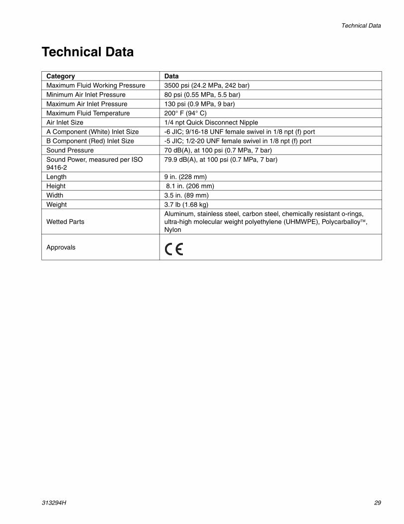
Category DataMaximum Fluid Working Pressure 3500 psi (24.2 MPa, 242 bar)Minimum Air Inlet Pressure 80 psi (0.55 MPa, 5.5 bar)Maximum Air Inlet Pressure 130 psi (0.9 MPa, 9 bar)Maximum Fluid Temperature 200° F (94° C)Air Inlet Size 1/4 npt Quick Disconnect NippleA Component (White) Inlet Size -6 JIC; 9/16-18 UNF female swivel in 1/8 npt (f) portB Component (Red) Inlet Size -5 JIC; 1/2-20 UNF female swivel in 1/8 npt (f) portSound Pressure 70 dB(A), at 100 psi (0.7 MPa, 7 bar) Sound Power, measured per ISO 9416-2
79.9 dB(A), at 100 psi (0.7 MPa, 7 bar)
Length 9 in. (228 mm)Height 8.1 in. (206 mm)Width 3.5 in. (89 mm)Weight 3.7 lb (1.68 kg)
Wetted PartsAluminum, stainless steel, carbon steel, chemically resistant o-rings, ultra-high molecular weight polyethylene (UHMWPE), Polycarballoy™, Nylon
Approvals

All written and visual data contained in this document reflects the latest product information available at the time of publication. Graco reserves the right to make changes at any time without notice.
Original instructions. This manual contains English. MM 313294
Graco Headquarters: MinneapolisInternational Offices: Belgium, China, Japan, Korea
GRACO INC. AND SUBSIDIARIES • P.O. BOX 1441 • MINNEAPOLIS MN 55440-1441 • USACopyright 2008, Graco Inc. All Graco manufacturing locations are registered to ISO 9001.
www.graco.comRevised 01/2012
Graco Standard WarrantyGraco warrants all equipment referenced in this document which is manufactured by Graco and bearing its name to be free from defects in material and workmanship on the date of sale to the original purchaser for use. With the exception of any special, extended, or limited warranty published by Graco, Graco will, for a period of twelve months from the date of sale, repair or replace any part of the equipment determined by Graco to be defective. This warranty applies only when the equipment is installed, operated and maintained in accordance with Graco’s written recommendations.
This warranty does not cover, and Graco shall not be liable for general wear and tear, or any malfunction, damage or wear caused by faulty installation, misapplication, abrasion, corrosion, inadequate or improper maintenance, negligence, accident, tampering, or substitution of non-Graco component parts. Nor shall Graco be liable for malfunction, damage or wear caused by the incompatibility of Graco equipment with structures, accessories, equipment or materials not supplied by Graco, or the improper design, manufacture, installation, operation or maintenance of structures, accessories, equipment or materials not supplied by Graco.
This warranty is conditioned upon the prepaid return of the equipment claimed to be defective to an authorized Graco distributor for verification of the claimed defect. If the claimed defect is verified, Graco will repair or replace free of charge any defective parts. The equipment will be returned to the original purchaser transportation prepaid. If inspection of the equipment does not disclose any defect in material or workmanship, repairs will be made at a reasonable charge, which charges may include the costs of parts, labor, and transportation.
THIS WARRANTY IS EXCLUSIVE, AND IS IN LIEU OF ANY OTHER WARRANTIES, EXPRESS OR IMPLIED, INCLUDING BUT NOT LIMITED TO WARRANTY OF MERCHANTABILITY OR WARRANTY OF FITNESS FOR A PARTICULAR PURPOSE.
Graco’s sole obligation and buyer’s sole remedy for any breach of warranty shall be as set forth above. The buyer agrees that no other remedy (including, but not limited to, incidental or consequential damages for lost profits, lost sales, injury to person or property, or any other incidental or consequential loss) shall be available. Any action for breach of warranty must be brought within two (2) years of the date of sale.
GRACO MAKES NO WARRANTY, AND DISCLAIMS ALL IMPLIED WARRANTIES OF MERCHANTABILITY AND FITNESS FOR A PARTICULAR PURPOSE, IN CONNECTION WITH ACCESSORIES, EQUIPMENT, MATERIALS OR COMPONENTS SOLD BUT NOT MANUFACTURED BY GRACO. These items sold, but not manufactured by Graco (such as electric motors, switches, hose, etc.), are subject to the warranty, if any, of their manufacturer. Graco will provide purchaser with reasonable assistance in making any claim for breach of these warranties.
In no event will Graco be liable for indirect, incidental, special or consequential damages resulting from Graco supplying equipment hereunder, or the furnishing, performance, or use of any products or other goods sold hereto, whether due to a breach of contract, breach of warranty, the negligence of Graco, or otherwise.
FOR GRACO CANADA CUSTOMERSThe Parties acknowledge that they have required that the present document, as well as all documents, notices and legal proceedings entered into, given or instituted pursuant hereto or relating directly or indirectly hereto, be drawn up in English. Les parties reconnaissent avoir convenu que la rédaction du présente document sera en Anglais, ainsi que tous documents, avis et procédures judiciaires exécutés, donnés ou intentés, à la suite de ou en rapport, directement ou indirectement, avec les procédures concernées.
Graco Information For the latest information about Graco products, visit www.graco.com.
TO PLACE AN ORDER, contact your Graco distributor or call to identify the nearest distributor.Phone: 612-623-6921 or Toll Free: 1-800-328-0211 Fax: 612-378-3505


![B737 NG - Aerocadet warnings, landing gear warnings, takeoff configuration warnings, ... Boeing B737 NG - Systems Summary [Warning Systems] Page 1. G](https://img.pdfslide.us/doc/110x75/5aac9a5a7f8b9aa9488d350f/b737-ng-warnings-landing-gear-warnings-takeoff-configuration-warnings-boeing.jpg)