Embed Size (px)
Citation preview
Energies 2014, 7, 4300-4315; doi:10.3390/en7074300
energies ISSN 1996-1073
www.mdpi.com/journal/energies
Article
Energy Management and Control of Electric Vehicles, Using Hybrid Power Source in Regenerative Braking Operation
Bo Long 1, Shin Teak Lim 2, Zhi Feng Bai 1, Ji Hyoung Ryu 2 and Kil To Chong 2,*
1 School of Mechanical, Electronic, and Industrial Engineering,
University of Electronic Science and Technology of China, Chengdu 611731, China;
E-Mails: [email protected] (B.L.); [email protected] (Z.F.B.) 2 Departments of Electronics & Information Engineering, Chonbuk National University, Jeonju 567,
Korea; E-Mails: [email protected] (S.T.L.); [email protected] (J.H.R.)
* Author to whom correspondence should be addressed; E-Mail: [email protected];
Tel.: +82-63-270-2478; Fax: +82-63-270-2394.
Received: 27 April 2014; in revised form: 27 June 2014 / Accepted: 1 July 2014 /
Published: 4 July 2014
Abstract: Today’s battery powered electric vehicles still face many issues: (1) Ways of
improving the regenerative braking energy; (2) how to maximally extend the driving-range
of electric vehicles (EVs) and prolong the service life of batteries; (3) how to satisfy the
energy requirements of the EVs both in steady and dynamic state. The electrochemical
double-layer capacitors, also called ultra-capacitors (UCs), have the merits of high energy
density and instantaneous power output capability, and are usually combined with power
battery packs to form a hybrid power supply system (HPSS). The power circuit topology of
the HPSS has been illustrated in this paper. In the proposed HPSS, all the UCs are in series,
which may cause an imbalanced voltage distribution of each unit, moreover, the energy
allocation between the batteries and UCs should also be considered. An energy-management
scheme to solve this problem has been presented. Moreover, due to the parameter
variations caused by temperature changes and produced errors, the modelling procedure of
the HPSS becomes very difficult, so an H∞ current controller is presented. The proposed
hybrid power source circuit is implemented on a laboratory hardware setup using a digital
signal processor (DSP). Simulation and experimental results have been put forward to
demonstrate the feasibility and validity of the approach.
OPEN ACCESS
Energies 2014, 7 4301
Keywords: electric vehicle; H∞ control; ultra-capacitor; hybrid power supply system;
energy management
1. Introduction
With the emergence of the energy crisis, electric vehicles (EVs) are attached with great importance
because of their high efficiency and environmentally friendly features. Hybrid electric vehicles (HEV),
plug-in electric vehicles (PEV) and fuel-cell electric vehicles (FEV) have been getting more attention
in recent years. Many famous enterprises have launched their feature EVs. PEVs still face several
challenges: (1) How to recover the braking energy more efficiently with minimum harm to the
batteries; (2) How to provide instantaneous and maximum power output when the EVs are in
accelerating or climbing operations; (3) How to maximally extend the mileage of PEVs.
Aiming at resolving the aforementioned challenges, a lot of work has been done so far in the last
decade. A hybrid power source system (HPSS), which was based on an ultra-capacitor-battery
combination is put forward to solve this problem. The ultra-capacitor, or electrochemical double-layer
capacitor, has great advantages compared to the standard electrolytic capacitor in high energy and
power density, high efficiency and cycling capability, and long endurance [1]. The latest capacitance
technology can reach up to 250 F/g, and the surface of the electrode is as high as 2000 m2/g [2–4].
The state-of-art on HPSS can be summarized as follows: In [5] Aharon and Kuperman elaborate
different battery-ultra-capacitor hybrid topologies. In [6], Ribeiro analyzed the utilization of
ultra-capacitors as energy storage for power quality applications and in order to overcome the power
delivery limitations of the batteries and the energy storage limitations of ultra-capacitors, a hybrid
energy storage system, which combines the two energy sources, has been proposed. A method of
optimizing the operation of a battery/ultra-capacitor hybrid energy storage system (HESS) is presented
in [7], where Thouthong, Raël and Davat proposed an energy-management scheme of a fuel cell
battery ultra-capacitor hybrid power source for vehicle applications. The state of the art of batteries,
ultra-capacitors, fuel cells, and hybrid energy storage systems for electric vehicles has been elaborated
in [8]. A semi-active battery-ultra-capacitor hybrid energy source is proposed in [9], in which, the
HPSS consists of an ultra-capacitor-assisted Li-Ion battery via a DC-DC converter. In [10], Cao and
Emadi proposed a new battery/ultra-capacitor hybrid energy storage system for electric drive vehicles
including electric, hybrid electric, and plug-in hybrid electric vehicles. The proposed design uses a
much smaller DC/DC converter working as a controlled energy pump to maintain the voltage of the
ultra-capacitor at a value higher than the battery voltage for mostly city driving conditions. The battery
will only provide power directly when the ultra-capacitor voltage drops below the battery voltage.
Except for the power circuit topology of the hybrid power supply system, modern control strategies
have been used in the control of ultra-capacitor/battery systems, and a model predictive control system
(MPC) for a hybrid battery-ultra-capacitor power source is proposed in [11]. The contribution of the MPC
method is that the state of battery charge, and the ultra-capacitor current and voltage are maintained
within predefined limits during the operation. Additionally, the controller allocates fast current changes
to the ultra-capacitor since it has the capability of instantaneous current charging and discharging.

Energies 2014, 7 4302
From the aforementioned previous works, we may know that much of the research work related to
HPSS has been done [12–15]. Yet few papers have been found illustrating energy-management and
coordination control strategies for the HPSS considering the parameter variations, especially, when the
EVs are in regenerative braking operation, how to allocate the braking energy between the UCs and
batteries has become an important issue, moreover, due to the parameter variations in HPSS, acquiring
an accurate model of the HPSS also becomes very difficult, and a more robust controller is needed for
the un-modelled component. In Section 2, we will first analyze the power circuit and operation
principles of HPSS, then, instantaneous charging current of both the ultra-capacitor and batteries in
energy regenerative braking operation is analyzed, after that, an optimal energy-management control
strategy which separates the consistent energy is discussed in Section 3, Finally, a H∞ for HPSS is
designed, weighing functions selection criteria for H∞ are elaborated in Section 4, to further
demonstrate the feasibility and utility of the proposed control scheme, experimental results are
presented in Section 5. Finally, the key points of this paper are concluded in Section 6.
2. Power Circuit and Operation Principles of the HPSS
2.1. Power Circuit and Operation Modes
Figure 1a gives the block diagram of the proposed HPSS for PEVs. Figure 1b gives the detailed
power circuit of the HPSS in use, in which, the UCs serve as the auxiliary energy system, and the
batteries’ vb, which serves as the main energy system, is directly connected to the load through
a DC-bus. The UCs are connected to the DC-bus via a bi-directional buck-boost DC/DC converter
which contains two power transistors (T11, T12) and an inductance L. The inductance is inserted
between the DC-link and the neutral-point of the DC/DC converter. In the proposed scheme, the UCs
are assigned as an auxiliary power source due to their capability of handling large instantaneous power
inputs and outputs. The UCs are installed at the DC/DC converter because it cannot provide consistent
power output. From Figure 1a, we know that in driving operation, the current which flows into the
motor is the sum of the battery current Ibat and ultracapacitor current Iuc. The proposed scheme can
satisfy both the steady and dynamic power requirements for the PEV. Therefore, how to manage the
energy between the two power sources is the key of this paper.
From Figure 1, we know that there are several operation modes in use. They can be categorized as
motoring and braking operations. For motoring operation, the HPSS has three work modes: (a) the
drive energy is solely supplied by the mains; (b) composite power supply mode—the drive energy
comes from both the UCs and batteries; (c) stand-by mode—both ultra-capacitors and power
accumulator batteries stop working, and the UCs are pre-charged by the DC-link batteries.
Similarly, for braking operation, the possible modes are: (d) the ultra-capacitors are charged by the
regenerative braking energy with priority; (e) UCs and battery pack are charged simultaneously;
(f) the UCs have been fully charged and the batteries are charged by the regenerative braking energy
generated by the motor.
In the following parts, Since (a), (b), (c) (d), (f) have already been described in [16], we will
concentrate on analyzing the regenerative braking procedure of the HPSS.

Energies 2014, 7 4303
Figure 1. Proposed hybrid power source for EVs. (a) System configuration of hybrid
power source system for EVs; (b) internal power circuit topology of HPSS.
(a)
(b)
2.2. Regenerative Braking Operation
Operation in regenerative braking happens when the EVs are in deceleration or running downhill,
regenerative braking can provide an electric braking torque for the motor, the direction of the braking
current Ibrake from the mains will change from the positive to negative direction. If the EVs are running
at high speed, the instantaneous braking power for the motor would be very big. In a conventional PEV
system, the batteries are controlled to absorb this energy, instantaneous and large charging current
might occur for braking control, and without being properly controlled, this charging current ibat might
be harmful to the batteries, such as causing fast internal temperature rise, which will shorten the
life-time of batteries, and sometimes, even cause serious explosions. The ultra-capacitor, by its nature,
has the capability of absorbing large currents and is suitable for this application.
Figure 2a shows the charging current direction of the ultra-capacitors when the EVs operate in
regenerative braking mode. The buck chopper power circuit is formed by the power transistor T11,
by-pass diode D11, D1, the loads (ultracapacitors) and the mains at DC-link. In ultra-capacitors, by
their nature, the charging current iuc can be large enough to keep the DC-link voltage at its reference value.
L
Buck‐Boost Converter
Ultracapacitors
Auxiliary Energy System
Batteries Motor Controller
Driving Motor
Ibat Ibb Iuc
M
T11
T12
Vb
LCu1
T4
T1
Buck-Boost DC/DC Converter
Cun
Motor Controller
Ultracapacitors
Batteries
Hybrid Power Source System
DC high speed circuit-breaker
FUSEK1

Energies 2014, 7 4304
The charging current of the batteries in Figure 2b happens after the instantaneous braking power is
being absorbed by the ultracapacitors, the consistent braking power can be recovered to the batteries.
In this situation, Power transistor T11 is always OFF. The high speed direct current circuit-breaker K1
of the mains should be closed.
The charging current of the batteries in Figure 2c occurs when an urgent electric braking
requirement occurs. In this circumstance, both the batteries and ultracapcitors are charged
simultaneously, hence, a large braking torque is provided and the EVs slow down very fast.
Figure 2. Operation principles of the HPSS in regenerative braking operation. (a) The UCs
is charged with priority; (b) the batteries are discharged; (c) the batteries and UCs are
charged simultaneously when an emergent braking operation is needed.
M
T11
T12
Vb
LCu1
T4
T1
Buck-Boost DC/DC Converter
Cun
Motor Controller
Ultracapacitors
Batteries
DC high speed circuit-breaker
FUSEK1
D11
D12
D1
D4
M
T11
T12
Vb
LCu1
T4
T1
Buck-Boost DC/DC Converter
Cun
Motor Controller
Ultracapacitors
Batteries
Hybrid Power Source System
DC high speed circuit-breaker
FUSEK1
D11
D12
D1
D4
(a) (b)
M
T11
T12
Vb
LCu1
T4
T1
Buck-Boost DC/DC Converter
Cun
Motor Controller
Ultracapacitors
Batteries
Hybrid Power Source System
DC high speed circuit-breaker
FUSEK1
D11
D10
D1
D4
(c)
3. Proposed Energy-Management under Regenerative Braking
From the aforementioned description of the charging current direction in regenerative braking operation,
we can know that the bidirectional DC-DC converter is assigned as an interface between the batteries
and the ultracapacitors. The combination of batteries and ultracapacitors has the merits of high power
density and specific energy. Hence, how to dynamically allocate the charging current between the
batteries and the ultracapacitors is the key issue.
In [17], Zhou et al. established a speed control and current limitation control methodology for the
energy management of an electric bus. This method can avoid the over-charging and discharging
current of the batteries, yet, it reduced the dynamic performance of the PEV. In [18], Schaltz et al. put
Energies 2014, 7 4305
forward a power allocation scheme for the two power sources, which is realized by way of limiting the
maximum power output of the batteries; this method has limitations on the improvement of the
power-out efficiency, moreover, this control strategy has the drawbacks of complicated computation
problems on the definition of average positive and negative power needs. Moreover, the influences of
battery/ultra-capacitor energy-storage sizing on extending the battery lifetime are discussed.
From the above analysis, we can conclude that the best way for energy allocation of HPSS is to
certify the needed power of EVs in use, which is decided according to the state of charge (SOC) of the
batteries and ultra-capacitors, then, the energy allocation scheme can be realized by fuzzy control
theory. Another solution is to put forward an objective optimization function which is composed
of minimum battery energy consumption, the real maximum power output of EVs, the SOC of
batteries and ultra-capacitors, the maximum output current of the batteries, and the variations of the
acceleration pedal.
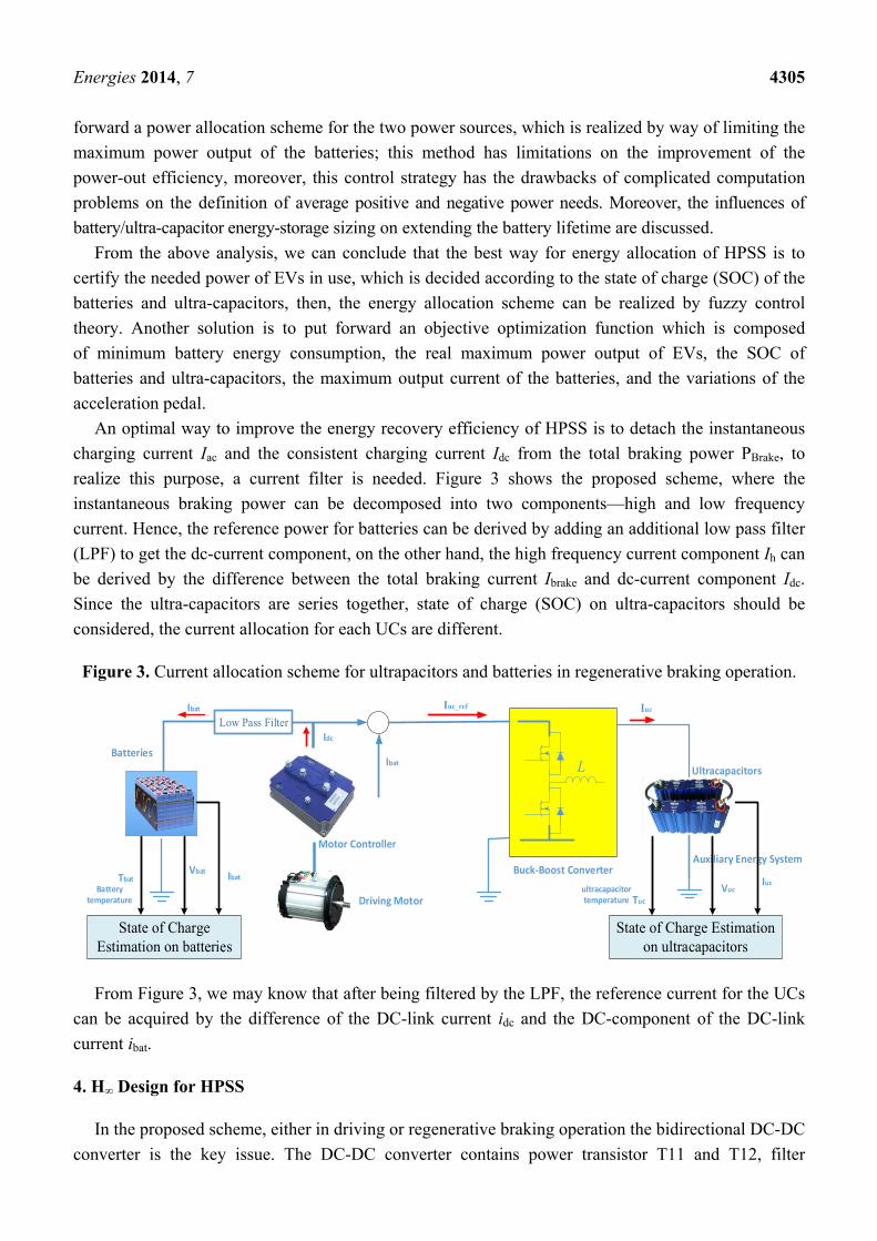
An optimal way to improve the energy recovery efficiency of HPSS is to detach the instantaneous
charging current Iac and the consistent charging current Idc from the total braking power PBrake, to
realize this purpose, a current filter is needed. Figure 3 shows the proposed scheme, where the
instantaneous braking power can be decomposed into two components—high and low frequency
current. Hence, the reference power for batteries can be derived by adding an additional low pass filter
(LPF) to get the dc-current component, on the other hand, the high frequency current component Ih can
be derived by the difference between the total braking current Ibrake and dc-current component Idc.
Since the ultra-capacitors are series together, state of charge (SOC) on ultra-capacitors should be
considered, the current allocation for each UCs are different.
Figure 3. Current allocation scheme for ultrapacitors and batteries in regenerative braking operation.
From Figure 3, we may know that after being filtered by the LPF, the reference current for the UCs
can be acquired by the difference of the DC-link current idc and the DC-component of the DC-link
current ibat.
4. H∞ Design for HPSS
In the proposed scheme, either in driving or regenerative braking operation the bidirectional DC-DC
converter is the key issue. The DC-DC converter contains power transistor T11 and T12, filter
L
Buck‐Boost Converter
Ultracapacitors
Auxiliary Energy System
Batteries
Motor Controller
Driving Motor
Ibat Iuc_ref Iuc
IdcLow Pass Filter
Ibat
State of Charge Estimation on batteries
State of Charge Estimation on ultracapacitors
IbatVbat
TbatBattery
temperature
IucVuc
Tucultracapacitor temperature
Energies 2014, 7 4306
inductance L, equivalent resistance of the UCs, batteries rbat and the motor, and the driving motor.
Since the structure of the two energy sources are similar, hence, the same equivalent circuit can be
used for modeling, in the following parts, we will conclude the mathematical model of the hybrid
power source system in regenerative braking operations.
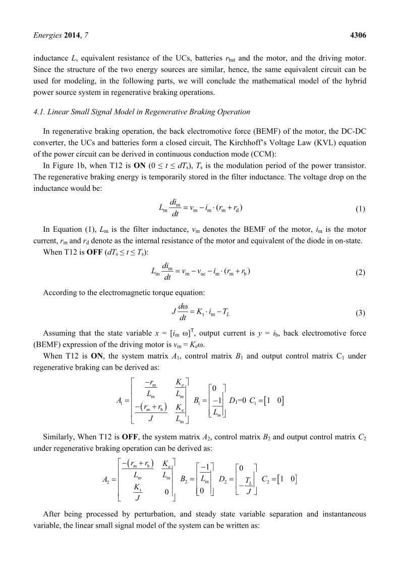
4.1. Linear Small Signal Model in Regenerative Braking Operation
In regenerative braking operation, the back electromotive force (BEMF) of the motor, the DC-DC
converter, the UCs and batteries form a closed circuit, The Kirchhoff’s Voltage Law (KVL) equation
of the power circuit can be derived in continuous conduction mode (CCM):
In Figure 1b, when T12 is ON (0 ≤ t ≤ dTs), Ts is the modulation period of the power transistor.
The regenerative braking energy is temporarily stored in the filter inductance. The voltage drop on the
inductance would be:
mm m m m d( )
diL v i r r
dt (1)
In Equation (1), Lm is the filter inductance, vm denotes the BEMF of the motor, im is the motor
current, rm and rd denote as the internal resistance of the motor and equivalent of the diode in on-state.
When T12 is OFF (dTs ≤ t ≤ Ts):
mm m uc m m b( )
diL v v i r r
dt (2)
According to the electromagnetic torque equation:
t mω
Ld
J K i Tdt
(3)
Assuming that the state variable x = [im ω]T, output current is y = ib, back electromotive force
(BEMF) expression of the driving motor is vm = Keω.
When T12 is ON, the system matrix A1, control matrix B1 and output control matrix C1 under
regenerative braking can be derived as:
em
m m
1m b e
m
Kr
L LA
r r K
J L
1
0
1
m
B
L
D1=0 1 1 0C
Similarly, When T12 is OFF, the system matrix A2, control matrix B2 and output control matrix C2
under regenerative braking operation can be derived as:
m b e
m m2
t 0
r r K
L LA
K
J
m2
1
0
LB
2
0
LD T
J
2 1 0C
After being processed by perturbation, and steady state variable separation and instantaneous
variable, the linear small signal model of the system can be written as:
Energies 2014, 7 4307
m b eb
m mmm b
t
(1 )0ˆ ˆ
00 00
ˆ ˆ1 0 1 0
r r D Kr D
L LLLx x X v
K
J
y D x X d
(4)
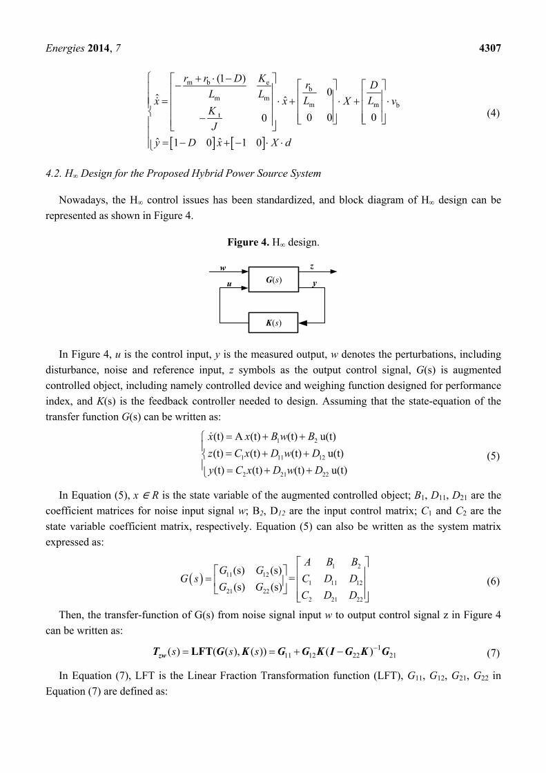
4.2. H∞ Design for the Proposed Hybrid Power Source System
Nowadays, the H∞ control issues has been standardized, and block diagram of H∞ design can be
represented as shown in Figure 4.
Figure 4. H∞ design.
In Figure 4, u is the control input, y is the measured output, w denotes the perturbations, including
disturbance, noise and reference input, z symbols as the output control signal, G(s) is augmented
controlled object, including namely controlled device and weighing function designed for performance
index, and K(s) is the feedback controller needed to design. Assuming that the state-equation of the
transfer function G(s) can be written as:
1 2
1 11 12
2 21 22
(t) A (t) (t) u(t)
(t) (t) (t) u(t)
(t) (t) (t) u(t)
x x B w B
z C x D w D
y C x D w D
(5)
In Equation (5), x R is the state variable of the augmented controlled object; B1, D11, D21 are the
coefficient matrices for noise input signal w; B2, D12 are the input control matrix; C1 and C2 are the
state variable coefficient matrix, respectively. Equation (5) can also be written as the system matrix
expressed as:
1 2
11 121 11 12
21 222 21 22
(s) (s)=
(s) (s)
A B BG G
G s C D DG G
C D D
(6)
Then, the transfer-function of G(s) from noise signal input w to output control signal z in Figure 4
can be written as:
111 12 22 21( ) ( ( ), ( )) ( )s s s LFTzwT G K G G K I G K G (7)
In Equation (7), LFT is the Linear Fraction Transformation function (LFT), G11, G12, G21, G22 in
Equation (7) are defined as:
u yG(s)w z
K(s)
Energies 2014, 7 4308
G11 = A, 12 1 2G B B , 21 1 2
TG C C , 11 12
2221 22
D DG
D D
In the design procedure of a feedback control system, performance requirements of the closed-loop
system include: robust stability, sensitivity to the disturbances, dynamic performance, and speed
response error both in steady state and steady-state. Among them, robust stability and sensitivity to
disturbance are especially important in a closed-loop system, and they are also the basic conditions for
normal operation of a system. In order to reduce the sensitivity to perturbation and improve the
robustness-stability of the system, special requirements are needed for the sensitivity-function in
finite-frequency range. Compound sensitivity optimization has particular merits; by selecting a proper
weighing function, it can force the system’s sensitivity function to be changeable within the expected
rule, thus satisfying as a result, the requirements of the closed-loop system.
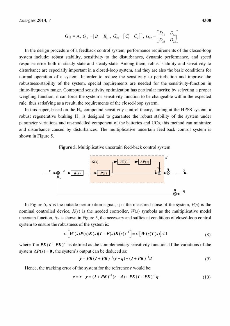
In this paper, based on the H∞ compound sensitivity control theory, aiming at the HPSS system, a
robust regenerative braking H∞ is designed to guarantee the robust stability of the system under
parameter variations and un-modelled component of the batteries and UCs, this method can minimize
and disturbance caused by disturbances. The multiplicative uncertain feed-back control system is
shown in Figure 5.
Figure 5. Multiplicative uncertain feed-back control system.
yrK(s)
-
e
G(s)d
++P(s)
W(s) ∆P(s)
In Figure 5, d is the outside perturbation signal, η is the measured noise of the system, P(s) is the
nominal controlled device, K(s) is the needed controller, W(s) symbols as the multiplicative model
uncertain function. As is shown in Figure 5, the necessary and sufficient conditions of closed-loop control
system to ensure the robustness of the system is:
1( ) ( ) ( )( ( ) ( )) ( ) ( ) 1s s s s s s s W P K I P K W T (8)
where 1( ) T PK I PK is defined as the complementary sensitivity function. If the variations of the
system ( )s 0P , the system’s output can be deduced as: 1 1( ) ( ) ( ) y PK I PK r η I PK d (9)
Hence, the tracking error of the system for the reference r would be:
1 1( ) ( ) ( ) e r - y I PK r d PK I PK η (10)
Energies 2014, 7 4309
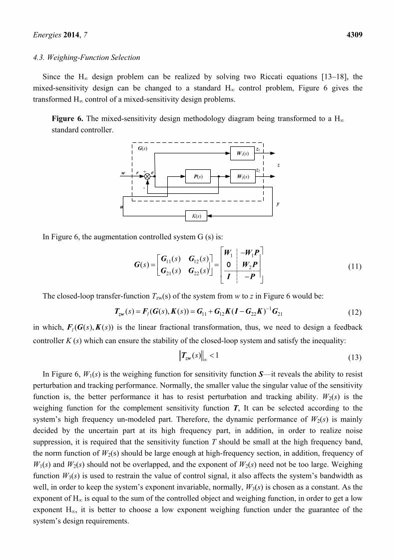
4.3. Weighing-Function Selection
Since the H∞ design problem can be realized by solving two Riccati equations [13–18], the
mixed-sensitivity design can be changed to a standard H∞ control problem, Figure 6 gives the
transformed H∞ control of a mixed-sensitivity design problems.
Figure 6. The mixed-sensitivity design methodology diagram being transformed to a H∞
standard controller.
In Figure 6, the augmentation controlled system G (s) is:
1 111 12
221 22
( ) ( )( )
( ) ( )
s ss
s s
W W PG G
G W PG G
I P
0 (11)
The closed-loop transfer-function Tzw(s) of the system from w to z in Figure 6 would be:
111 12 22 21( ) ( ( ), ( )) ( )ls s s zwT F G K G G K I G K G (12)
in which, ( ( ), ( ))l s sF G K is the linear fractional transformation, thus, we need to design a feedback
controller K (s) which can ensure the stability of the closed-loop system and satisfy the inequality:
( ) 1szwT (13)
In Figure 6, W1(s) is the weighing function for sensitivity function S—it reveals the ability to resist
perturbation and tracking performance. Normally, the smaller value the singular value of the sensitivity
function is, the better performance it has to resist perturbation and tracking ability. W2(s) is the
weighing function for the complement sensitivity function T, It can be selected according to the
system’s high frequency un-modeled part. Therefore, the dynamic performance of W2(s) is mainly
decided by the uncertain part at its high frequency part, in addition, in order to realize noise
suppression, it is required that the sensitivity function T should be small at the high frequency band,
the norm function of W2(s) should be large enough at high-frequency section, in addition, frequency of
W1(s) and W2(s) should not be overlapped, and the exponent of W2(s) need not be too large. Weighing
function W3(s) is used to restrain the value of control signal, it also affects the system’s bandwidth as
well, in order to keep the system’s exponent invariable, normally, W3(s) is chosen as a constant. As the
exponent of H∞ is equal to the sum of the controlled object and weighing function, in order to get a low
exponent H∞, it is better to choose a low exponent weighing function under the guarantee of the
system’s design requirements.
G(s)
w e+
-
u
W1(s)
W2(s)
z1
z2
z
y
P(s)
K(s)
r
Energies 2014, 7 4310
After being regulated many times using Matlab/robust toolbox, the frequency weighing function of
the H∞ of the EVs in regenerative braking operation can be written as:
1( ) 0.1 100 / 0.01W s s s (14)
2 ( ) 50 /120W s s (15)
3( ) 50W s (16)
According to the mathematical model described in Equation (4), and the suggested weighing
function in Equations (14)–(16), The frequency weighing composite sensitivity H∞ can be derived as: 8 3 2
3 4 2
1.386 10 1.471 1379 330.5( )
1.165 10 241.7 1.252b
s s sK s
s s s
(17)
Assuming that the sampling time T = 0.002 s, after being processed by bilinear transformation, the
discrete controller in regenerative braking mode would be derived from Equation (17) as: 4 3 6 2 4 6
3 2
2.252 10 7.189 10 2.251 10 7.29 10( )
1.158 0.6839 0.84194d
z z zK z
z z z
5. Experimental Results
In order to validate the proposed scheme, an HPSS system hardware platform using a digital signal
processor (DSP)-TMS320F28335 (Texas Instruments, Dallas, TX, USA) has been set up in the
laboratory (see Figure 7). The PID controller parameters (actually, a PI controller instead of a PID
controller is utilized when in use in case of system oscillation which may be caused by an
improper choice of the kd coefficient) in experiments are chosen by simulation verifications using
Matlab/SimPowersystem. Specifications of the HPSS used in the hardware platform are listed in
Table A1 in the Appendix. The parameters of PID controller are kp = 1.5, ki = 0.002, kd = 0, sample
time Ts = 4 μs, respectively. The experiment is performed with two main objectives:
(a) In motoring operation, when the PEV needs an instantaneous and peak power output, and
meanwhile, the ultra-capacitors are fully charged and have stored enough energy, the HPSS is
controlled as a boost DC-DC converter which works in parallel driving mode. The additional
energy is provided by the ultra-capacitors and batteries.
(b) Since the ultra-capacitor has the merits of high energy and power density, and high efficiency
of charging and discharging current. In deceleration or braking operation, the ultra-capacitors
have priority to be charged. A constant power charging control strategy is implemented in this
paper, which means position of the pedal determines the braking power command. The
maximum braking power reference is limited to 10 kW.
Energies 2014, 7 4311
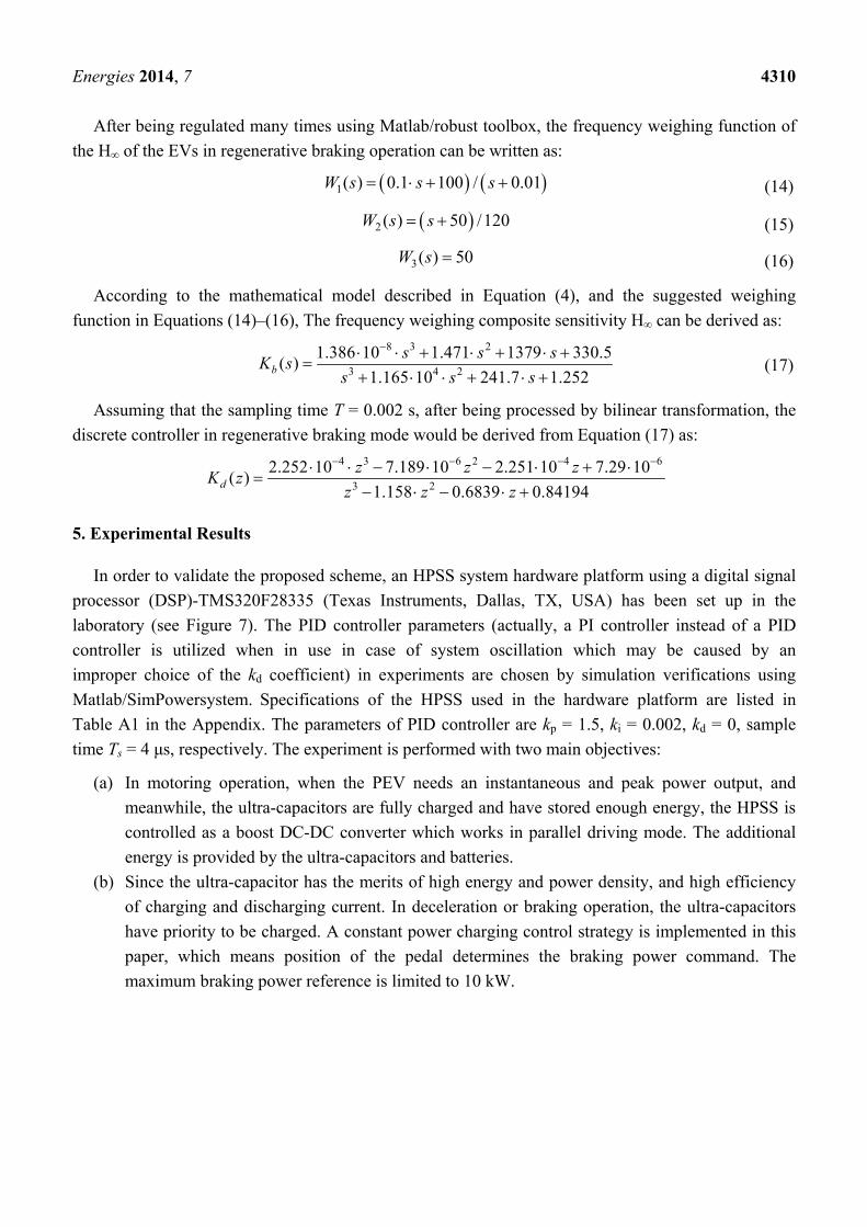
Figure 7. Hardware setup for experiments. (a) Electric vehicle; (b) controller for HPSS
using DSP.
(a) (b)
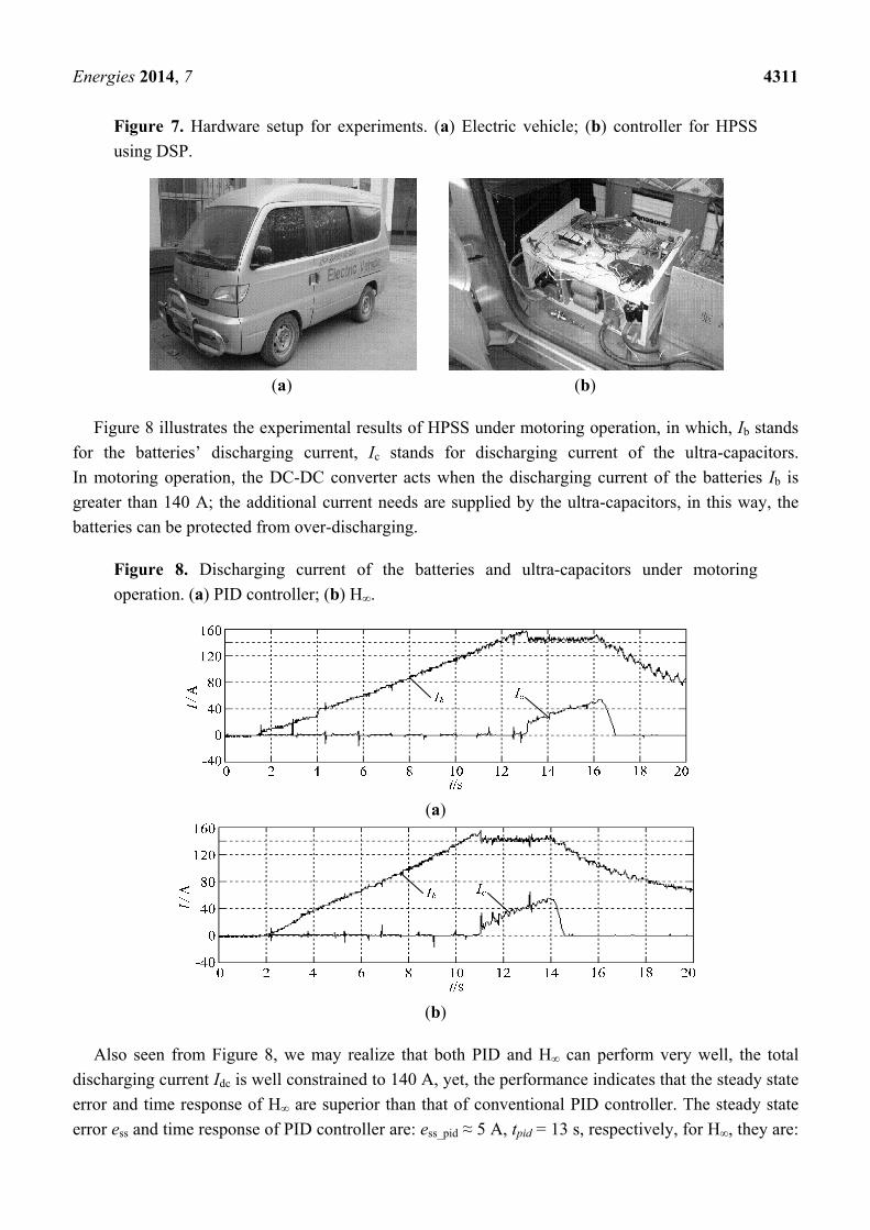
Figure 8 illustrates the experimental results of HPSS under motoring operation, in which, Ib stands
for the batteries’ discharging current, Ic stands for discharging current of the ultra-capacitors.
In motoring operation, the DC-DC converter acts when the discharging current of the batteries Ib is
greater than 140 A; the additional current needs are supplied by the ultra-capacitors, in this way, the
batteries can be protected from over-discharging.
Figure 8. Discharging current of the batteries and ultra-capacitors under motoring
operation. (a) PID controller; (b) H∞.
(a)
(b)
Also seen from Figure 8, we may realize that both PID and H∞ can perform very well, the total
discharging current Idc is well constrained to 140 A, yet, the performance indicates that the steady state
error and time response of H∞ are superior than that of conventional PID controller. The steady state
error ess and time response of PID controller are: ess_pid ≈ 5 A, tpid = 13 s, respectively, for H∞, they are:
Energies 2014, 7 4312
ess_H∞ ≈ 2 A, tH∞ = 11 s. Hence, the H∞ has much faster time response (2 s) than the PID controller,
which is caused by a large integral variable existing in the PID controller. The larger the integral
coefficient is, the slower the time response would be. On the contrary, Equation (18) is discrete, which
does not have any integral component, so it is easier for fast implementation. It should also be noted
that the smaller the upper limit of batteries’ discharging current is, the larger its available capacitance
would be, but this upper limit is constrained by the maximum energy stored in the ultra-capacitors. If
the energy stored in the ultra-capacitor is large enough, it would be better if the batteries’ reference
discharging current is restrained to be a relatively smaller value. This would be beneficial for
improving the available capacitance of the batteries. In our experiment, the energy stored in the
ultra-capacitors is relatively smaller, that is why the batteries’ discharging current is set to 140 A.
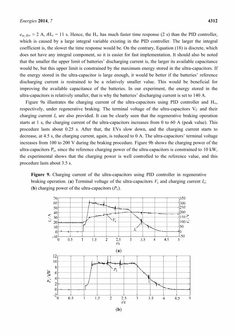
Figure 9a illustrates the charging current of the ultra-capacitors using PID controller and H∞,
respectively, under regenerative braking. The terminal voltage of the ultra-capacitors VC and their
charging current Ic are also provided. It can be clearly seen that the regenerative braking operation
starts at 1 s, the charging current of the ultra-capacitors increases from 0 to 60 A (peak value). This
procedure lasts about 0.25 s. After that, the EVs slow down, and the charging current starts to
decrease, at 4.5 s, the charging current, again, is reduced to 0 A. The ultra-capacitors’ terminal voltage
increases from 100 to 200 V during the braking procedure. Figure 9b shows the charging power of the
ultra-capacitors Pc, since the reference charging power of the ultra-capacitors is constrained to 10 kW,
the experimental shows that the charging power is well controlled to the reference value, and this
procedure lasts about 3.5 s.
Figure 9. Charging current of the ultra-capacitors using PID controller in regenerative
braking operation. (a) Terminal voltage of the ultra-capacitors Vc and charging current Ic;
(b) charging power of the ultra-capacitors (Pc).
(a)
(b)
Energies 2014, 7 4313
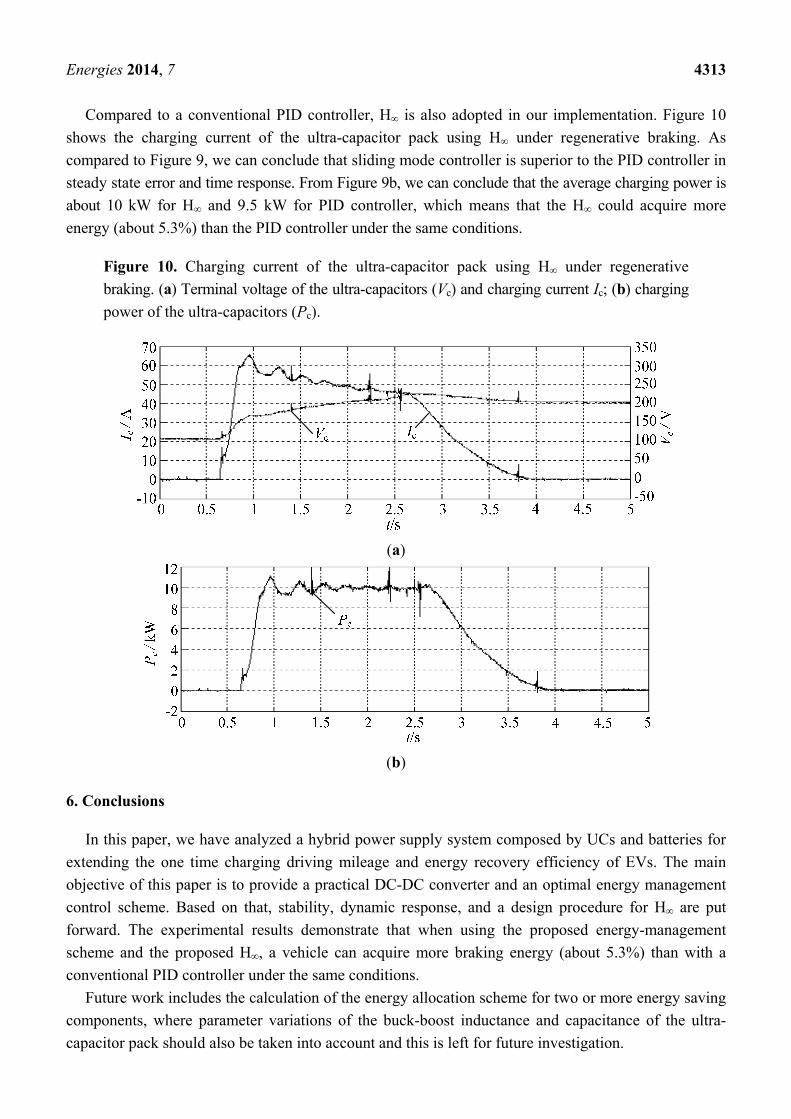
Compared to a conventional PID controller, H∞ is also adopted in our implementation. Figure 10
shows the charging current of the ultra-capacitor pack using H∞ under regenerative braking. As
compared to Figure 9, we can conclude that sliding mode controller is superior to the PID controller in
steady state error and time response. From Figure 9b, we can conclude that the average charging power is
about 10 kW for H∞ and 9.5 kW for PID controller, which means that the H∞ could acquire more
energy (about 5.3%) than the PID controller under the same conditions.
Figure 10. Charging current of the ultra-capacitor pack using H∞ under regenerative
braking. (a) Terminal voltage of the ultra-capacitors (Vc) and charging current Ic; (b) charging
power of the ultra-capacitors (Pc).
(a)
(b)
6. Conclusions
In this paper, we have analyzed a hybrid power supply system composed by UCs and batteries for
extending the one time charging driving mileage and energy recovery efficiency of EVs. The main
objective of this paper is to provide a practical DC-DC converter and an optimal energy management
control scheme. Based on that, stability, dynamic response, and a design procedure for H∞ are put
forward. The experimental results demonstrate that when using the proposed energy-management
scheme and the proposed H∞, a vehicle can acquire more braking energy (about 5.3%) than with a
conventional PID controller under the same conditions.
Future work includes the calculation of the energy allocation scheme for two or more energy saving
components, where parameter variations of the buck-boost inductance and capacitance of the ultra-
capacitor pack should also be taken into account and this is left for future investigation.

Energies 2014, 7 4314
Acknowledgments
This work was simultaneously supported by the Fundamental Research Funds for the Central
Universities of China (NO. ZYGX2012J095), China Postdoctoral Science Foundation Funded Project
(2013M542266), Natural Science Foundation of China (NSFC) (No. 61106107), and supported by the
National Research Foundation of Korea (NRF) funded by the Government of South Korea (MEST)
(No. 2013009458) and (No.2013068127). The authors would like to thank all the reviewers for their
advices and suggestions on improving this paper.
Author Contributions
Bo Long and Zhi Feng Bai conceived and developed the idea behind the present research and
proposed the Hinf controller for HPSS under regenerative braking. Bo Long, Shin Teak Lim and
Ji Hyoung Ryu have carried out the hardware setup of HPSS, literature review and manuscript
preparation. Final review, including final manuscript corrections, was done by Kil to Chong and
Bo Long.
Appendix
Table A1. Parameters of the hybrid power source system used in experiments.
Elements Parameters Values
Battery pack
Rated capacity Pe 245 Ah Battery type Lead-acid
Recommended charging and discharging current 20A/800 A Quality of each unit 55 kg
Batteries used in series 10 Battery manufacture factory Panasonic
Ultra-capacitor pack
Rated energy saving 43 kJ Capacitance CUC 0.7 F
Number of ultra-capacitors in series 2 Rated voltage 350 V
Rated charging and discharging current <400 A
Parameters of EVs
Mass of the EV 1500 kg Rated power output 20 kW Radios of the tire 0.287 m
Transmission ratio of the gear 4.7
Conflicts of Interest
The authors declare no conflict of interest.
References
1. Grbović, P.J.; Delarue, P.; Le Moigne, P.; Bartholomeus, P. The ultracapacitor-based controlled
electric drives with braking and ride-through capability: Overview and analysis. IEEE Trans.
Ind. Electron. 2011, 58, 925–936.

Energies 2014, 7 4315
2. Ellenbogen, J.C.; Halper, M.S. Supercapacitors: A brief overview. Available online:
http://www.mitre.org/sites/default/files/pdf/06_0667.pdf (accessed on 27 June 2014).
3. Burke, F.A. Ultracapacitors: Present and Future. In Proceedings of Advanced. Capacitor World
Summit: Washington, DC, USA, 14–16 July 2003.
4. Jia, J.; Wang, J.; Cham, Y.T.; Wang, Y.; Han, M. Electrical characteristic study of a hybrid
PEMFC and ultracapacitor system. IEEE Trans. Ind. Electron. 2010, 57, 1945–1953.
5. Aharon, I.; Kuperman, A. Topological overview of powertrains for battery-powered vehicles with
range extenders. IEEE Trans. Power Electron. 2011, 26, 868–876.
6. Ribeiro, P.F.; Johnson, B.K.; Crow, M.L.; Arsoy, A.; Liu, Y. Energy storage systems for
advanced power applications. Proc. IEEE 2001, 89, 1744–1756.
7. Thounthong, P.; Raël, S.; Davat, B. Energy management of fuel cell/battery/supercapacitor hybrid
power source for vehicle applications. J. Power Source 2009, 193, 376–385.
8. Khaligh, A.; Li, Z. Battery, ultracapacitor, fuel cell, and hybrid energy storage systems for
electric, hybrid electric, fuel cell, and plug-in hybrid electric vehicles: State of the art.
IEEE Trans. Veh. Technol. 2010, 59, 2806–2814.
9. Kuperman, A.; Aharon, I.; Malki, S.; Kara, A. Design of a semiactive battery-ultracapacitor
hybrid energy source. IEEE Trans. Power Electron. 2013, 28, 806–815.
10. Cao, J.; Emadi, A. A new battery/ultracapacitor hybrid energy storage system for electric, hybrid,
and plug-in hybrid electric vehicles. IEEE Trans. Power Electron. 2012, 27, 122–132.
11. Hredzak, B.; Agelidis, V.G.; Jang, M. A model predictive control system for a hybrid
battery-ultracapacitor power source. IEEE Trans. Power Electron. 2014, 29, 1469–1479.
12. Camara, M.B.; Gualous, H.; Gustin, F.; Berthon, A.; Dakyo, B. DC/DC converter design for
supercapacitor and battery power management in hybrid vehicle applications—Polynomial control
strategy. IEEE Trans. Ind. Electron. 2010, 57, 587–597.
13. Garcia, P.; Fernandez, L.M.; Garcia, C.A.; Francisco, J. Energy management system of
fuel-cell-battery hybrid tramway. IEEE Trans. Ind. Electron. 2010, 57, 4013–4023.
14. Moreno, J.; Ortuzar, M.E.; Dixon, J.W. Energy-management system for a hybrid electric vehicle,
using ultracapacitors and neural networks. IEEE Trans. Ind. Electron. 2006, 53, 614–623.
15. Mazumder, S.K.; Jedraszczak, P. Evaluation of a SiC DC/DC converter for plug-in hybrid-electric-vehicle
at high inlet-coolant temperature. IET Power Electron. 2011, 4, 708–714.
16. Lahyani, A.; Venet, P.; Guermazi, A.; Troudi, A. Battery/supercapacitors combination in
uninterruptible power supply (UPS). IEEE Trans. Power Electron. 2013, 28, 1509–1522.
17. Zhou, H.; Bhattacharya, T.; Tran, D.; Siew, T.S.T.; Khambadkone, A.M. Composite energy
storage system involving battery and ultracapacitor with dynamic energy management in
microgrid applications. IEEE Trans. Power Electron. 2011, 26, 923–930.
18. Schaltz, E.; Khaligh, A.; Rasmussen, P.O. Influence of battery/ultracapacitor energy-storage
sizing on battery lifetime in a fuel cell hybrid electric vehicle. IEEE Trans. Veh. Technol. 2009,
58, 3882–3891.
© 2014 by the authors; licensee MDPI, Basel, Switzerland. This article is an open access article
distributed under the terms and conditions of the Creative Commons Attribution license
(http://creativecommons.org/licenses/by/3.0/).