Embed Size (px)
DESCRIPTION
All rights reserved by IEC. For educational and knowledge use only.Coping with the Energy ChallengeThe IEC’s role from 2010 to 2030 Smart electrifi cation - The key to energy efficiency - White Paper
Citation preview
®
Coping with the Energy ChallengeThe IEC’s role from 2010 to 2030 Smart electrifi cation - The key to energy effi ciency
White Paper

3
Introduction
Over the next decades, the world will face
increasing challenges to supply energy in suffi cient
quantities, while reducing carbon emission levels.
Saving energy and using energy more effi ciently
are key to addressing these challenges. Ours is a
connected world and energy effi ciency solutions
will need to work together, safely, everywhere
to make a real impact. Not just in the developed
world, but in developing countries as well.
However, without metrics all efforts to reduce
and optimize energy consumption are doomed
to remain small and insignifi cant. As the fi rst IEC
President, Lord Kelvin, always said: “If you cannot
measure it, you cannot improve it!”. This statement
is especially true here: without measurement
you can’t credibly demonstrate energy effi ciency
improvements. The IEC provides and will continue
to provide many of the measuring standards that
are the basis for benchmarking, energy audits and
compliance assessments.
But the IEC also holds an important piece of
the solution for overall energy effi ciency – smart
electrifi cation.
Electricity is the most easily controllable form of
energy. The IEC believes that electricity will be
the most important contributor to climate change
mitigation. It is easily controlled and weightless. It
is easier to transport and distribute and cleaner at
the point of use than most other energy sources,
and it can be produced cleanly at the point of
generation. It represents the most effi cient way of
generating and consuming power and the most
intelligent approach for future global efforts to
economize energy.
With this paper, the IEC is laying the foundation for
the electrical energy effi ciency discussion.
To defi ne where IEC’s work needs to be focused,
the IEC has studied the wide array of energy
effi ciency opportunities and technologies that are
available. Based on this the IEC has developed a
model projecting what it believes is likely to happen
in the next 20 years.
This document is a summary of those refl ections
and constitutes a roadmap and recommendations
that will allow the IEC to develop the many
standards that are needed to enable highest short-
and long-term energy effi ciency outcomes, today
and tomorrow.
This document has been prepared by the IEC
Market Strategy Board (MSB). The MSB was set
up by the IEC to identify the principal technological
trends and market needs in the IEC’s fi elds of
activity. It sets strategies to maximize input from
primary markets and establishes priorities for the
technical and conformity assessment work of the
IEC, improving the IEC’s response to the needs of
innovative and fast-moving markets.
The MSB comprises 15 chief technology offi cers
as members appointed from industry, and (ex
offi cio) the IEC Offi cers.
Executive summary
In Section 1, the problem of energy demand,
the energy challenge and the additional climate
challenge are stated with a short summary of
salient action points.
Section 2 summarizes available levers and their
potential to reduce CO2 emissions and increase
energy effi ciency.

4
Introduction
In Section 3 a defi nition for energy effi ciency is
provided, with a review of technology innovations
that already today have the potential to signifi cantly
increase energy effi ciency in power generation.
This section also outlines the use of electricity and
potential effi ciency improvements in buildings and
homes, industry and transportation.
Section 4 addresses the potential to reduce CO2
emissions in power generation as well as carbon
capture and storage.
Section 5 provides a sensitivity analysis regarding
the overall impact of different energy scenarios and
their ability to reduce long-term carbon emission
levels.
Section 6 demonstrates what needs to change in the
energy chain to achieve the CO2 emission levels
that can help humanity to mitigate climate change.
Section 7 offers a summary of critical success
factors for implementing energy solutions, and
in Section 8 the MSB, author of the present
document, presents key recommendations for the
IEC.

5
Table of contents
Section 1 Problem statement 9
1.1 Economy 9
1.2 Population 9
1.3 Energy demand 9
1.4 Distribution of the population and energy demand by region 9
1.5 Distribution by type of energy produced 9
1.6 Distribution by type of energy used 10
1.7 Carbon dioxide (CO2) emissions 10
1.8 The challenge 11
Section 2 Framework for solutions 13
2.1 Parameters for the response 13
2.2 Targets for action 13
CO2 = P x [E / P] x [CO
2 / E]
2.3 Levers available 14
2.4 Perspectives for evolution 16
Section 3 Energy effi ciency 19
3.1 Energy effi ciency: a defi nition 19
3.2 The current electrical energy chain 19
3.3 Fossil-fuel power generation 21
3.4 Co-generation (combined heat and power, CHP) 22
3.5 Fuel cells, including uses in combination with CHP & coal gasifi cation 22
3.6 Transmission and distribution (T&D) 23
3.7 Use of electricity in buildings 23
3.8 Use of electricity in industry 25
3.9 Electrifi cation of transport 25

6
Table of contents
Section 4 Reducing carbon dioxide emissions – “decarbonization” 27
4.1 Renewable energies (RE) 27
4.2 Nuclear generation 28
4.3 CO2 (carbon) capture and storage (CCS) 29
Section 5 Are these measures enough? A sensitivity analysis 31
5.1 Business as usual 31
5.2 Improvements using immediate technologies from Sections 3 and 4 31
5.3 More aggressive strategies in electricity generation and other areas 32
5.4 Results of the sensitivity analysis 32
Section 6 Redesign: the future energy chain 33
6.1 The need for redesign and the role of reference architectures 33
6.2 Grid architectures 33
6.3 Energy and electricity end-use architectures 35
6.4 Energy and electricity storage 38
6.5 Micro-grids 39
6.6 Issues raised by the future energy chain 39
Section 7 Critical success factors for implementing solutions 43
Section 8 Recommendations 45
8.1 Recommended evolution in the IEC’s fundamental orientation 45
8.2 General recommendations 46
8.3 Detailed recommendations 48
8.4 Technology list 48

7
Table of contents
Annexes 51
Annex A World primary energy demand by fuel in the Reference Scenario 51
Annex B Scenarios for greenhouse gas emissions and temperature rise 52
Annex C Energy-related CO2 emission reductions in the 550 and 450 Policy Scenarios 53
Annex D Systematic evaluation of effi ciency and CO2 reduction 54
Annex E Combined-cycle generating plant 56
Annex F Integrated coal gasifi cation and fuel cell, IGFC 57
Annex G Analysis of energy use in buildings – some fi gures 58
Annex H Example of a reference architecture for material handling 62
Annex J Generation IV nuclear energy 63
Annex K Carbon capture and storage 65
Annex L Sensitivity analysis of CO2 reduction measures 66
Annex M The DESERTEC project 70

9
The basis for much of the information in this
section is the International Energy Agency's IEA
World Energy Outlook 2008 1, augmented with
information from the electricity domain.
1.1 Economy
The global economy is set to grow four-fold
between now and 2050, and national growth
could approach ten-fold in countries such as
China and India.
This promises economic benefi ts and huge
improvements in people's standards of living,
but also involves much more use of energy.
Unsustainable pressure on natural resources
and on the environment is inevitable if economic
growth is not de-coupled from energy demand,
and energy demand from fossil fuel consumption.
1.2 Population
World population is expected to grow from an
estimated 6.5 B in 2006 to 8.2 B in 2030, at an
annual average rate of 1 %. This rate will probably
slow progressively over the projection period in line
with past trends: population expanded by 1.4 %
per year from 1990 to 2006. The population of
non-OECD countries as a group continues to grow
most rapidly.
1.3 Energy demand
Growing populations and industrializing countries
create huge needs for electrical energy. In the
1 The most recent edition, IEA World Energy Outlook 2009,
does not present many signifi cant differences.
Section 1 Problem statement
reference scenario of the International Energy
Agency (IEA), which assumes that there are no new
governmental policies other than those of mid-2008
(the so-called business-as-usual scenario, BAU),
projected world primary energy demand increases
by 45 % between 2006 and 2030 – an average
annual rate of growth of 1.6 % – and doubles (i.e.
a 100 % increase) by 2050. Electricity demand will
triple by 2050.
1.4 Distribution of the population
and energy demand by region
Today 1.6 B people have no access to
electrical energy; however, they will require
electricity in the coming decades. Furthermore,
most of the new inhabitants of the planet will live
in today’s developing countries. Therefore any
measure envisaged affecting energy effi ciency or
consumption should take into account the fact that
the new energy demand will be situated in those
countries where energy distribution infrastructures
are not yet at the right level to satisfy increasing
demand.
In 2006, cities accounted for 67 % of the world’s
energy consumption and 71 % of global energy-
related CO2 emissions, at a higher rate per capita
than the countryside.
1.5 Distribution by type of energy
produced
The combined power-generation and heat sector
absorbs a growing share of global primary energy
demand over the projection period. Its share

10
Problem statement
reaches over 42 % in 2030 compared with 38 %
in 2006.
Fossil fuels remain the leading sources of
energy – roughly 80 % in 2030 (see Annex A).
Coal remains the leading input for power generation
and heat, its share of total inputs holding steady at
about 47 % over the outlook period. Oil remains
the dominant fuel in the primary energy mix, but its
share drops to 30 % in 2030, from 34 % in 2006,
while the share of gas rises from 21 % to 23 %.
Nuclear power’s contribution falls from 16 % in
2006 to 13 % in 2030. Hydropower’s share remains
steady at 6 %. Inputs from non-hydro renewables
– photovoltaic (PV), wind, biomass and waste – will
grow worldwide at an average rate of 6.2 % per
year between 2006 and 2030, the fastest rate of
all energy sources, with their share rising to 10 %
but still remaining limited as a source of energy in
2030.
1.6 Distribution by type of energy
used
According to the IEA World Energy Outlook
2008, industry, transport and buildings/
services 2 are almost equal primary energy
consumers (1/3 each). If we examine not primary
but electrical energy, it is essential to note that
almost half is consumed by industry, with all other
uses making up the remainder.
In industry and buildings/services electricity
is dominant, with the fastest rate of growth. In
transport, on the other hand, electricity is almost
absent, but its developing use could be one
important part of the solution. Growth is most rapid
in industry and slowest in buildings and services.
2 In this paper, the phrase “buildings and services” also
includes agriculture.
1.7 Carbon dioxide (CO2) emissions
Today CO2 emissions related to energy use
are at a level of 28 Gt (Gigatonnes of CO2
per annum), which represents 70 % of total
greenhouse gas (GHG) emissions. Electricity
generation represents something approaching a
half of this, at about 11 Gt.
If no specifi c action is taken (in the so-called
reference or business-as-usual scenario, BAU), the
IEA projects in its Energy Technology Perspectives
2008 that 42 Gt will be emitted in 2030 and 62 Gt
in 2050; such a scenario could lead to a rise in
global temperatures of up to 6 °C (see Table 1.1).
This is clearly not sustainable. The United Nations
Intergovernmental Panel on Climate Change (UN
IPCC) has demonstrated that, in order to limit the
temperature rise to 2 °C, the concentration of CO2
in the atmosphere must stay below 450 ppm (parts
per million), and consequently the world must
not emit in 2050 more than half the GHG being
emitted today. Annex B and Annex C contain
a comparison of three scenarios, the BAU, the
450 ppm and an intermediate one at 550 ppm.
Table 1.1 | CO2 emissions in the BAU
scenario (ref.: Table L.1)
CO2
emissions
related to
energy use
including :
CO2
emissions
from
electricity
generation
Today 28 Gt 10.8 Gt
2030 42 Gt 17.8 Gt
2050 62 Gt 29 Gt

11
Problem statement
1.8 The challenge
We are faced with a double challenge: a purely
energy challenge, and in addition a climate
challenge. A new strategy is needed, which cannot
be local but must be global. It must decouple
energy consumption from economic development
and growth.
In short : the challenge is ensuring energy availability
and preserving the environment. The key elements
are the following:
1) Stabilizing climate impact from fossil fuel
use
2) Meeting the energy demand of a growing
global population
3) Bringing electricity to the 1.6 B people
without access
4) Ensuring stable and secure energy access
for all nations
5) Transporting electricity long distances
from where it is generated to where it is
used
In fi gures, the challenge for the year 2050 is :
1) energy demand will increase by a factor
of two,
2) simultaneously, CO2 emissions must be
reduced by a factor of two,
therefore the quantitative result to be achieved
corresponds to a factor of four.
The present document is produced by an
organization whose responsibilities do not extend to
all forms of energy, but only to electrical. However,
the coherence of the discussion requires that in
certain contexts all forms of energy production and
use should be treated together.


13
2.1 Parameters for the response
1) Climate change mitigation is economically
meaningful, even essential
As indicated in the Stern Review Report 3, no
action would cost from 5 % to 20 % of the
global Gross National Product, where action
will cost only 1 % of GNP.
2) Climate change mitigation is politically
supported
Political commitments for CO2 emission reduc-
tion will frame action for the next 30 years :
Kyoto originally mandated a reduction of
8 % of emissions with respect to the 1990
level over the period to 2012
The EU Spring Council in March 2007 fi xed
a reduction of at least 20 % of the 1990
level as the basis, by 2020
Less than 50 % of the 1990 level by 2050 is
the intention, according to some countries
Copenhagen follow-up, Bonn, Mexico, ...
3) A key factor in the response must be
electricity
31 % of global fossil fuel used each year
goes to producing electricity
1/3 of fi nal energy use in industry comes
from electricity, with a growth rate of 2.7 %
Energy used in buildings/services also
comes one-third from electricity, with a
growth rate of 2.3 %
3 http://webarchive.nationalarchives.gov.uk/+/http://www.
hm-treasury.gov.uk/independent_reviews/stern_review_
economics_climate_change/stern_review_report.cfm.
Section 2Framework for solutions
Introducing electricity into transport will
enable economies by allowing control
Electrifi cation of various other uses of
energy will also increase effi ciency
2.2 Targets for action
A useful statement of the problem might be the
following: the more people there are, the more
energy is used; the more energy is used, the
more carbon dioxide is emitted; the more carbon
dioxide is emitted, the more harm is done to the
climate. A little more formally: at any point in time,
total emissions of CO2 are equal to the population,
multiplied by the quantity of energy used per
person, multiplied by the quantity of CO2 emitted
per unit of energy used :
CO2 = P × [E/P] × [CO
2/E]
CO2 = Quantity of CO
2 emitted
P = Population
[E/P] = Energy used per head of population
[CO2/E] = CO
2 emitted per unit of energy used
We will assume that P, population, is a given (see
Section 1.2). We must therefore act on the [E/P]
and [CO2/E] quantities in order to reduce CO
2
emissions (see also Annex C).
14
Framework for solutions
Acting on the [E / P] quantity is energy
effi ciency. It may be infl uenced in the short,
medium or long term. Short-term action
may already give signifi cant results. The two
strategic elements are effi ciency in electricity
use, and using electricity to replace a quantity
of fossil fuel use.
Acting on the [CO2 / E] quantity is
decarbonization of energy, choosing energies
which emit less or no carbon (renewables,
biofuels, carbon capture and storage (CCS)
and nuclear energy). Results are medium- and
long-term.
Some of the tactics which may be used are
investment – investing to achieve reduction of
energy use per person, and CO2 emission per unit
of energy used; technologies – identifying those
technologies and strategies which are most cost-
effective in achieving CO2 reduction (note that
these technologies and strategies will be different
in different countries); and individual action –
investment by individuals as well as by governments
(e.g. buying energy-effi cient appliances or paying
a premium on electricity prices to be used for
investment), and changing of behaviour to choose
actions which use less energy.
2.3 Levers available
2.3.1 Inventory of actions and their
potential
The following actions are available to reduce CO2
emissions related to electricity generation and use.
In most cases they concern mature technologies.
Reduce energy used at end-use level by
increased energy effi ciency
– Today available and proven technologies
can bring savings of up to 30 %
– The issue is massive implementation and
not only with newly built but also with ex-
isting installations
– End-use behaviour may be changed to re-
duce activities requiring much energy
Reduce transmission & distribution losses
(9 % today)
– The benefi t will be in line with the existing
proportion
Improve generation effi ciency (only one third of
primary energy used is available as electrical
energy)
– Existing power generation units will require
time and resources to be converted
– Coal is still available and cheap in many
countries
Increase renewable and specifi cally decentral-
ized generation, almost CO2-free
– There are economic limitations (need to
subsidize cost) and physical constraints
(availability of land, wind, …)
Change the fossil fuel mix towards less-
CO2-emitting fuels (less coal, co-generation,
nuclear, Combined Gas Cycle Turbines, …)
– As for generation effi ciency, the existence
of power plants which cannot be converted
will delay real results
Limit CO2 emission at generation by capture
and storage of carbon
– The technology as well as a viable business
model remain to be demonstrated
Make transportation, today 99 % fossil-fuel
(oil)-dependent, more energy-effi cient with
electricity

15
Framework for solutions
2.3.2 Measuring and evaluating possible
responses
Electricity is a key factor in energy effi ciency, on
condition that its use is evaluated and controlled.
Measurement and evaluation depend crucially on
a few basic concepts. Calculations should be in
terms of electrical energy as far as possible, and
verifi ed, so as to realize the benefi ts of control. For
the whole electrical energy cycle from generation
to consumption, i.e. for each of generation,
transmission and distribution and in each
application sector, EEE indicators should be defi ned
and effi ciency should be measured at each stage
within each sector. For every value measured, the
improvement which may be achieved by applying
Best Available Technology (BAT) should be
recorded. The reduction in CO2
emissions should
be based on full explanatory information on
generation resources and any additional resources
used; performance information, such as effi ciency
of generation, storage, and transmission; and CO2
emissions calculated by life cycle analysis (LCA) of
the infrastructure processes (see also Annex D).
In summary, two aspects are vital :
1) A systemic approach must be used which
takes the whole cycle into consideration
2) Measurement and evaluation are
necessary at each stage
The transport sector will gradually gain in
importance, especially when electric vehicles
become popular, but for the moment it has not
been considered in this subsection.
2.3.3 Effects of electrifi cation
Evaluation methods for energy effi ciency should
account for the effects of electrifi cation, i.e. the
conversion of energy-consuming tasks from
another source (typically fossil fuel) to electricity.
Substantial reductions may be expected,
primarily because electricity can be extremely
well controlled and measured, as well as through
its versatility for different applications. In general,
the net reduction in energy consumed is equal to
the difference between the reduction achieved by
electrifi cation, and the energy consumed by the
act of electrifi cation itself (see Figure 2.1).
2.3.4 Effects of information &
communications technology (ICT)
Evaluation methods for energy effi ciency should
also account for the intelligent introduction or
extension of ICT. For example, if electronic com-
munications replace the movement of people, the
consumption of fossil fuel will decrease. In general,
the net reduction in energy consumed is equal to
the difference between the reduction achieved by
the use of ICT, and the energy consumed by the
ICT tools themselves (see Figure 2.2).
Total reduction inenergy consumption = – Energy consumed in
implementing electrifi cationReduction in useful energy
consumption by electrifi cation
Figure 2.1 | Reducing energy consumption by electrifi cation

16
Framework for solutions
2.3.5 Behaviour changes
An enormous effect may be anticipated from
behavioural changes on the part of individuals
and society. This may run from the decision – as
suggested above – to hold a “meeting” by electronic
means, through the choice of environmentally
neutral means of transport, to totally changing the
population’s leisure pursuits, and will involve among
other triggers spontaneous individual action out
of concern for nature, emulation and changes in
fashion, non-compulsory (e.g. fi nancial) incentives
and compulsory regulations. While from society’s
point of view behaviour changes may prove to be
the decisive lever and therefore must be stressed
in all relevant contexts, this paper will not attempt
detailed analyses or recommendations. This is
because for the IEC, as in other technical contexts
and in the domain of international standards
generally, it makes no sense to act (or even to
express opinions) in advance of the relevant signals
from society and governments.
2.4 Perspectives for evolution
Energy generation today is mainly centralized,
energy transmission and distribution take place in
one direction only – from the generating plant to the
consumer – and energy is used by consumers who
only see the fi nal result and have no information
about energy usage in general. In Table 2.3 and
a brief commentary we sketch some foreseeable
developments.
For electricity generation, it may be expected
that, by 2020, energy production will still be mainly
centralized, using fossil fuels, but decentralized
production at the place of consumption will be
starting, using renewable energies (between 10 %
and 20 %). Keeping in mind this evolution and plans
for centralized renewable production, by 2050 it
seems relevant to expect to progress from about
8 % of total energy consumption coming from
renewable energy today, to about 40 %.
For transmission & distribution, major AC/DC
grids will be interconnected and the consumer
will combine consumption and production of
energy. Grid design will evolve to a network of
interconnected small and large grids. Figure 6.1
shows a grid diagram which illustrates energy
generation, transport & distribution.
For energy usage, there will be a two-way
relationship between the producer and the
consumer, energy consumption measurement
allowing fl exible and negotiated strategies of use.
Regarding buildings/services, buildings will
be active players, not only consuming but also
producing energy. Thanks to information and
communication technology (ICT) they will have the
capacity to adapt to changes in internal conditions
(e.g. different levels of activity) and to conditions
in the grid. All building facilities will be integrated
into an overall building and energy management
system, using ICT and distributed sensors.
Electric vehicles will have interfaces to integrate
them into the grid, and energy storage technology
will be used.
Total reduction inenergy consumption = – Energy consumed
by the ICT tools usedReduction in useful energy consumption by use of ICT
Source : “Deliverable 1 : Defi nition”, Focus Group on ICTs and Climate Change, ITU-T
Figure 2.2 | Reducing energy consumption by use of ICT

17
Framework for solutions
Table 2.3 | Perspectives for evolution
Today 2020 2030 and further
Generation Centralized Centralized (with more
higher-effi ciency thermal
and nuclear)
Decentralized
Renewables (10 %-20 %)
Centralized fossil and
nuclear
Centralized &
decentralized
renewables (40 %-45 %)
Microgrids
Transmission
and
distribution
Large-scale
Power fl ow : one-way,
controlled by information
technology (IT)
Power fl ow: mostly
one-way, UHVAC and
UHVDC, optimally
controlled by IT
Major grids using
UHVAC and UHVDC,
optimally controlled by IT
Interconnected grids
Small-scale
Power fl ow: one-way
Starts changing from
one-way to two-way
Power fl ow: two-way
Development and
introduction of control
by IT
Power fl ow: two-way
Interconnected and
optimally controlled by IT
Usage Consumers have no
information on usage
Smart usage data
Consumers on the way
to becoming producers
also
Consumers can optimize
their consumption,
production and CO2
emission by energy
management systems
Deployment of highly
effi cient end use


19
Section 3Energy effi ciency
3.1 Energy effi ciency : a defi nition
Energy effi ciency encompasses the overall effi -
ciency of human activities using energy, not simply
the measurable effi ciency of a single process. It
is therefore based on two complementary effi cien-
cies: the effi ciency of a given action or process –
doing the same but with less energy; and the ef-
fi ciency of the choices made – changing systems
and social behaviour so as to use less energy al-
together.
To illustrate the fi rst aspect, optimization for electri-
cal and electronic components may be achieved by
developing minimum effi ciency performance stan-
dards (MEPS). As a further example, both aspects
will be needed to improve the energy effi ciency of
industrial activities: individual processes must be
optimized, but in addition an overall architecture
using a systemic approach will allow selecting and
redefi ning processes so that global effi ciency is
augmented.
In Energy Technology Perspectives 2008 the IEA
has identifi ed energy effi ciency as the cheapest and,
in the short and medium term, the most effective
means of combating climate change.
Energy effi ciency offers a triple-win outcome:
1) reduced CO2 emissions,
2) saving on scarce natural resources and
reducing their depletion, and
3) reduced energy costs.
3.2 The current electrical energy
chain
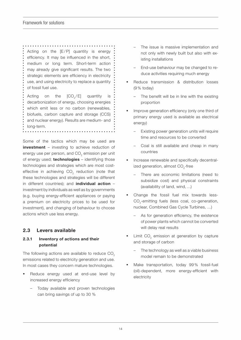
Electricity generation today represents 31 % of
total global fossil fuel use, and around 40 % of all
energy-related CO2 emissions. However, of the
fuel used to generate electricity, two thirds are
lost in generation and another 9 % in transmission/
distribution (see Figure 3.1).
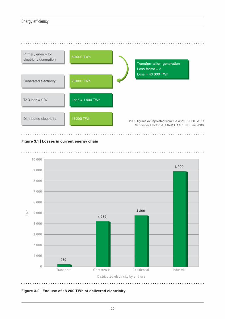
In end use almost half goes to industrial
applications, and of the rest residential buildings
and service / commercial buildings each use about
a half (see Figure 3.2).
In summary :
Only one-third of primary energy used in
generation is transformed into electricity.
Losses in transmission and distribution amount
to about 9 %.
In end use,
– the quantities of electricity used in build-
ings/services and industry are almost
equal;
– the quantity of electricity used in transport
is very limited at the moment.
The implications of this are as follows :
Proven technologies can today save up to 30 %,
so energy effi ciency at end-use level should be
implemented immediately and massively. The
role of standards is to foster deployment.
20
Energy effi ciency
T&D loss = 9 %
60 000 TWh
20 000 TWh
18 200 TWh
Primary energy for
electricity generation
Generated electricity
T&D loss = 9 %
Distributed electricity
60 000 TWh
Transformation-generation
Loss factor = 3
Loss = 40 000 TWh
20 000 TWh
Loss = 1 800 TWh
18 200 TWh2009 fi gures extrapolated from IEA and US DOE WEO
Schneider Electric JJ MARCHAIS 15th June 2009
Figure 3.2 | End use of 18 200 TWh of delivered electricity
Distributed electricity by end use
10 000
9 000
8 000
7 000
6 000
5 000
4 000
3 000
2 000
1 000
0
TW
h
250
Transport Commercial Residential Industrial
4 250
4 800
8 900
Figure 3.1 | Losses in current energy chain

21
Energy effi ciency
An increase in the effi ciency of generation
can give signifi cant results, but research &
development for new technologies need time
to be implemented. The role of standards is to
support the development of new technologies.
In transmission and distribution (T&D) a
proportional reduction in the percentage loss
will not have much impact in the steady state,
since the average loss rate is not high. However,
as energy needs and especially the quantity of
electricity distributed grows, each percent loss
is signifi cant. There are also specifi c situations
where T&D loss is currently much higher than
the average, where again a greater impact can
be expected.
See Section 5 for an analysis of the effects of
improvements at various stages in the energy
chain.
3.3 Fossil-fuel power generation
Large-scale centralized generation will continue
to have a key role in the production of electricity,
and improvement of technology in this area – in
addition to renewable energy – is therefore also
important. The following are most signifi cant for
fossil-fuel generation :
Improvements in the effi ciency of thermal
power generation
Technology transfer of these improvements to
all relevant countries
Capture and storage of CO2 (see Section 4.2)
Ideally less fossil fuel should be used, both in order
to reduce CO2 emissions and because of depletion
of the natural resource. At the same time, in reality,
fossil fuels will continue to play an important part
in power generation in the future. It is therefore
desirable to continue or expand R&D in fossil-fuel
power generation in order to improve generation
effi ciency, reduce CO2 emission to the atmosphere
or both.
For the purposes of CO2 reduction, spreading
conventional but up-to-date technologies through
international cooperation is also important,
because the situation of thermal power generation
varies by country.
3.3.1 Combined cycle (natural gas)
Combined cycle power generation is a method
of generating electric power that combines a gas
turbine with steam turbines. By employing a high-
temperature gas turbine in the high-temperature
section and by effectively recycling the exhaust
energy of this section in the steam system, a
higher thermal effi ciency may be achieved in
comparison with steam turbine generation. The most
advanced type of combined cycle has achieved an
effi ciency of up to 59 %, mainly by raising the inlet gas
temperature of the gas turbine to 1 500 °C. Combined
cycle can follow fl uctuations in demand as start-
up and shutdown operations are straightforward.
R&D is continuing in order to achieve even higher
effi ciencies, for example a thermal effi ciency of up
to 62 % with gas temperatures up to 1 700 °C (see
Annex E).
3.3.2 Pulverized coal combustion (PCC)
with supercritical steam
As many countries including developed countries
are highly dependent on coal (e.g. USA : 50 %), and
the coal reserves-to-production fi gure is assumed
to be 147 years (higher than oil – 41 years – or
natural gas – 63 years ), improvement of thermal
effi ciency in coal-fi red power generation may play
a large role in the reduction of CO2 emissions.
Various methods exist or are under development.
Pulverized coal combustion (PCC) blows the
pulverized coal with air to a boiler plant. PCC
improves thermal effi ciency through a higher
combustion temperature, and also emits smaller
quantities of polluting gases such as SOx or NO
x.

22
Energy effi ciency
Thermal effi ciency has been continuously improved
mainly by raising steam temperature and steam
pressure; an advanced type of PCC achieves a
thermal effi ciency of around 43 %-45 %. R&D for
PCC is currently aiming to raise steam temperatures
as high as 700 °C, which could improve thermal
effi ciency to 50 %.
3.3.3 Integrated Gasifi cation Combined
Cycle (Coal), IGCC
IGCC is a further innovation beyond pulverized
coal combustion. IGCC presents slightly higher
effi ciencies of 45 %-48 %, compared with 40 %-
42 % for conventional pulverized coal generation.
Two types of IGCC, an air-blown system which
enables lower auxiliary power consumption and an
oxygen-blown system which enables easier CO2
capture, are being developed and under fi eld test
by many countries, including US, UK and Japan.
Some commercial IGCC plants are planned. For
further application, some technical issues such
as the combination with CO2 capture and storage
technology are being addressed.
3.4 Co-generation (combined heat
and power, CHP)
Co-generation, which is also called Combined
Heat and Power (CHP), produces electricity
and hot water or steam simultaneously from the
same power source. By this method fuel could
theoretically be used to almost 100 % effi ciency.
Average performance would vary according to
how well the relative demands for heat (e.g. hot
water, steam) and for electricity corresponded
to the supply. A higher average value for the
effi ciency would be achieved in regions where
conditions require parallel supply of hot water or
steam and electric power, such as the Netherlands
or Scandinavia.
3.5 Fuel cells, including uses in
combination with CHP & coal
gasifi cation
The fuel cell is a device which produces electricity
from fuel and oxidant. Fuel cells are said to perform
at a higher effi ciency than heat engines as they are
independent of Carnot effi ciency. Though there
are still many issues, such as a requirement for
large cost reductions or longer life expectancy, the
fuel cell has additional advantages such as quiet
operation and modular construction that is easily
scalable. Thus fuel cells are expected to be widely
applied in many fi elds such as combined heat
and power (CHP – see Section 3.4) or for mobile
phones.
As for micro-CHP, which is expected to improve
energy effi ciency in the residential sector, an
advanced residential cogeneration system exists
in Japan (see Figure 3.3). In 2005, the New Energy
Foundation (NEF) started a large-scale fi eld test of
a Proton-Exchange membrane Fuel Cell (PEFC) for
introduction to the market. In four years 3 307 units
were installed and provided a 1.3 t CO2 reduction in
the total of 5.2 t per year per living unit (household).
The units started commercialization in Japan in
2009.
Many types of fuel cell are now in research and
development to overcome the issues and fi nd wide
application. Integrated Coal Gasifi cation Fuel Cell
Combined Cycle (IGFC) is an advanced application
of the fuel cell. It consists of an oxygen-blown coal
gasifi er, a gas turbine, a solid oxide fuel cell (SOFC)
and a steam turbine, and is expected to achieve
thermal effi ciency of up to 60 %, which is much
higher than conventional pulverized generation or
even integrated gas combined cycle (IGCC). Field
tests to develop the technology to produce coal
gas for fuel cells are now going on in Japan (see
Annex F).

23
Energy effi ciency
3.6 Transmission and distribution
(T&D)
We have seen that the effects on energy effi ciency
which may be expected from improvements in
T&D are limited, given their comparatively small
part in total energy use. It is however worthwhile to
examine the situation, since today’s well understood
centralized network will soon be complemented by
decentralized sources. Reduction of transmission/
distribution loss plays a role in the reduction of
CO2 emission especially because the loss rate
in many countries is high or may be liable to
reduction. Upgrading transmission/distribution
voltage, installation of power plants near the
demand (including dispersed generation or on-site
generation), development and adoption of low-
loss-rate equipment are all assumed to be effective
measures to reduce network loss.
However, the location and confi guration of power
plants and the intensity and distribution of the
demand vary greatly by country and according
to circumstances (e.g. resource availability, site
acquisition). Consequently the confi guration of the
power system cannot be unifi ed throughout the
world, and those measures that will principally be
effective will be quite different.
General alignment on best practices should lead
to an improvement of about 3 % on losses. Ultra-
high voltage AC, UHVAC (AC transmission whose
highest voltage exceeds 1 000 kV) and UHVDC
(DC transmission whose highest voltage exceeds
800 kV) are examples of advanced technology for
loss reduction by upgrading transmission voltages.
Superconducting cable may be mentioned as an
example of low-loss-rate equipment.
3.7 Use of electricity in buildings
Energy use in buildings (residential & tertiary,
i.e. services) is around 40 % of total energy
Figure 3.3 | Micro-combined-heat-and-power (micro-CHP) unit, Japan

24
Energy effi ciency
consumption; the electricity used is about half of
all electricity used anywhere (see Figure 3.2). Both
are targeted for signifi cant savings in the coming
decade, through both electrical energy effi ciency
and electrifi cation. Life-cycle analysis demonstrates
how critical energy effi ciency is throughout the
lifetime of a building. Optimizing energy usage by
allowing only the necessary energy and only when
necessary is key during the whole life cycle.
In the residential sector (households) energy use
and consumption are strongly driven by and
correlated with income. The non-residential
buildings segment covers a large range : offi ce
buildings, hospitals, commercial malls, railway
stations, etc. Some of these contain heavy
processes such as data centres. In fact, use of
ICT equipment is increasing exponentially in both
homes and offi ces: it can represent up to 1 000 KWh
per year per household in developed countries,
with up to 30 % consumed in standby mode. In
non-residential buildings electricity represents
around 50 % of energy used, and furthermore is
key for control of the use of other fuels such as that
for heating (see Annex G).
In both residential and non-residential buildings
noticeable progress in energy effi ciency has
been made during recent decades, in heating or
appliances for example. However, more effort is
needed in the control of electricity usage in order
to achieve effi ciency. Electricity has therefore now
become critical, not only in use directly as energy
but also in measurement, automation and control,
and in permanent monitoring of energy use. Proven
technology is available, so that the issue is real
implementation, specifi cally in existing buildings.
Existing levers to improve electrical energy
effi ciency today :
Use of low-consumption, high-effi ciency loads
(lighting systems, motors, power capacitors,
transformers, cables)
Optimization of the use of these loads through
intelligent automation and control (energy
management systems)
Implementation of procedures and tools to
monitor and maintain the systems
Enabling effi ciency and optimizing end use
with automation & control : energy management
systems are a fundamental part of the overall
solution, since they allow optimized use of energy,
general reliability and sustainability of performance.
Low-consumption products functioning when
not needed still consume energy (lamps, motors,
electronics on standby, ...). A 2 °C variation in
temperature setting on heating or cooling can
consume up to 10 % additional energy, hence
small drifts can have signifi cant consequences.
Automation and control are essential for
optimization of energy usage:
They allow consuming only what is necessary,
when and where necessary
They allow correcting “bad habits” and
improving behaviour
They can easily be installed in existing sites
and improve existing performance
They complement energy-effi cient end-use
products to improve overall usage performance
Examples of solutions: presence and light detec-
tors, timers, variable-speed drives, electric motor
systems’ automation & control, programmable
logic controllers (PLCs).
Renovation of existing buildings for better
energy effi ciency is also critical. Because
buildings have a long lifetime, construction of
new buildings on existing sites proceeds slowly
(typically less than 2 % per year are replaced).
Renewable energy such as that from photovoltaic
cells or heat pumps is well adapted to either
residential or commercial/service buildings and
should be extensively developed.

25
Energy effi ciency
Grid connection will need to be managed. More
and more ICT-based applications are developing
in commercial and service buildings, and some
applications (such as health applications in
hospitals) are becoming critical.
Strengthening energy effi ciency through
quality, reliability and continuity of supply
can avoid expensive waste and restart costs. The
constantly maintained high quality of an installation
is a guarantee of optimized consumption. Examples
of solutions: uninterruptible power supplies,
generating sets and automatic transfer switches,
fi lters.
Measuring and monitoring is the basis of
diagnosis and control, and is therefore needed
to guarantee durable energy effi ciency and the
limiting of CO2 emissions. Examples of solutions:
smart metering systems, monitoring systems
and services, energy management systems and
services.
The real issue today is to activate all
levers and implement existing and proven
technologies. As described above, the issue
is not understanding what needs to be done, or
fi nding new technologies and solutions. It is true
that there is some progress with existing solutions
in new buildings, but they are poorly implemented
in existing buildings, and a key factor hindering
progress is the slow construction rate. This is
why renovation is crucial. (Note that 80 % of
the buildings which will exist in 2020 have already
been built.)
3.8 Use of electricity in industry
Industry uses almost half of all electricity produced,
so it is vital that effi ciency measures be taken.
Many industry sectors are energy-intensive, and
they have already economized energy (energy
consumption per tonne of crude steel halved from
1960 to 2005, for example). With respect to these
available methods, it is very important to identify
the Best Available Technology (BAT) and best
practices in each sector, and to spread them as
widely as possible so as to realize the potential
economies. However, many possibilities for further
economies exist – most industrial processes
still use 50 % more energy than the theoretical
minimum. Reducing the amount of waste (which
takes energy to produce) is also required.
A major barrier has been a complex of non-
technological diffi culties: even existing technolo-
gies have mostly not been implemented, some-
times for structural reasons (such as company-
internal incentives for minimizing capital investment
rather than running costs), sometimes for political
reasons (policy incentives missing or misdirected).
Benchmarking is useful to identify areas where
energy effi ciency can be improved, but it is diffi cult,
especially for whole systems, because it is subject
to competition. However, it is urgent to develop the
reference architectures (one example is given in
Annex H, another in Figure 6.4) and best practices
which will enable benchmarking, and publish these
in standards or recommendations. One important
component of EEE in industry is to use electricity
(and ICTs, of course) to monitor and control the use
of other types of energy; these other energies have
to be incorporated in the reference architectures
together with electrical energy.
Probably 70 % of the electricity used by
industry goes to driving electric motors, so an
architecture approach to motor systems is a high
priority. Many technical methods and optimizations
already exist; their global and effective application
is urgently needed. Examples of technologies that
may need to be considered include permanent
magnets, matrix converters, reluctance motors,
in situ calibration of instruments and regeneration
and harmonics in the supply.
3.9 Electrifi cation of transport
In this area in particular, energy effi ciency can
be improved by electrifi cation – increasing
signifi cantly the 1 % or so of electricity consumed

26
Energy effi ciency
by transport in the world and simultaneously
decreasing net energy use and CO2 emissions.
Individual road vehicles are a promising candidate
for electrifi cation. A new-generation electric vehicle
(EV) has been developed with the use of lithium-
ion rechargeable batteries. EVs have the following
advantages compared to cars using petrol :
Less emission of CO2 : reduced CO
2 emissions
even if the electricity is generated from oil
Improvement of the urban environment: no
exhaust gases, less noise
At the current stage of development, the following
technological components need advances in order
to resolve issues preventing the further spread of
EVs :
Expensive battery: cost reduction by R&D and
mass production
Large and heavy battery: downsizing and
weight reduction by R&D
In addition to cars, (increased) electrifi cation of
public and freight transport needs also to be
examined seriously in order to reduce energy use
and emissions.
Electrifi cation of transport will have an impact
on grid and infrastructure design, but will also
offer additional possibilities; aspects include
load balancing, metering and the charging
infrastructure.

27
Section 4Reducing carbon dioxide emissions − "decarbonization"
4.1 Renewable energies (RE)
RE are those methods of obtaining energy
which can operate indefi nitely without emitting
greenhouse gases, and they are important not only
for energy effi ciency and decarbonization. Many
RE installations are categorized as distributed
generation (DG). DG allows a single house to
generate electricity, but also very remote areas
to be electrically self-suffi cient. Combined with
advanced grid connection and control systems,
energy storage systems and possible government
incentives, this may allow new types of arrangement,
leading to changes in the electric power industry,
and possibly persuading areas that are not using
electricity to do so. These secondary infl uences,
which would allow a further reduction of CO2, may
include electric vehicles in cities and desalination
in remote areas, for example.
The key to achieving the challenging goals in the
medium to long term is the technology aspect
rather than economics, according to the IEA report.
A wide range of developments beyond currently
popular RE technologies is needed. It extends from
the material level, such as new solid-state power
devices and new silicon purifi cation technology, to
highly integrated digital power distribution systems.
Once these R&D activities take place properly, the
450 policy scenario (see 1.7 and Annex B) could
be within reach.
4.1.1 Hydropower generation
Large-scale hydropower has been and will be
taking a leading role among all renewable energies.
Its increase in developed countries will be limited,
because most areas suitable for hydropower have
already been used. However, in large transitional
and developing countries there is still a huge
potential, and hydropower will contribute the most
to clean power generation.
Mini-hydro systems have a history of long and
stable operation in many countries. Some are
reported to have been working for more than a
century. The environmental load is much smaller
than that of large-scale hydropower generation. In
addition, mini-hydro systems are useful in remote
areas and developing countries.
4.1.2 Wind power
Among renewable technologies wind power is the
most successful one, and installed capacity exceed-
ed 73.9 GW at the end of 2006. Wind power has
been signifi cantly popular in Germany, Spain, US,
India, Italy, Denmark and so on. The cost is around
USD 0.10-0.14/kWh. The connection to the grid is
critical due to associated technical issues such as
the frequency fl uctuation of output by non-regu-
lar and non-control converters and non-matching
of grid capacity. These issues are sometimes re-
garded as obstacles to wider exploitation of wind
systems. Issues associated with maintenance and
stable operation, which will grow with the market,
may be standardized, with the scope of the stan-
dard expanding as it incorporates storage.
4.1.3 Solar thermal power generation
Solar thermal power is expected to provide
inexpensive electricity, and relatively large-scale
systems have been demonstrated in the US, the
EU and the Middle East.

28
Reducing carbon dioxide emissions − "decarbonization"
4.1.4 Solar photovoltaic electricity
Among renewable energy technologies, solar pho-
tovoltaic (PV) electricity is expected to be one of
the most effective, not only in developing coun-
tries but in developed countries such as Germany,
Japan, US, Spain and Italy. The adoption of PV has
been dramatically promoted by various incentives
such as feed-in tariffs, tax credits and government
aid. Total world installed capacity exceeded 10 GW
at the end of 2008.
The cost of the power generated may be as much
as USD 0.45/kWh, which needs to be reduced.
4.1.5 Geothermal power generation
Geothermal power generation operates stably in
commercial contexts in the US, the Philippines,
Mexico, Italy, Indonesia, Japan and other countries,
and large test systems have been demonstrated
in various areas. Global capacity was roughly
8 900 MW in 2005.
4.1.6 Heat pump systems
Heat pump (HP) systems are not always classifi ed
as renewable energy, but the technology
represents an effi cient use of energy. In Japan
HP systems have been becoming popular rapidly
and have demonstrated an effi ciency exceeding
60 %. Japan possesses a very large stock in gas
air conditioning and there are more than 100 000
installations due to government aid.
4.2 Nuclear generation
Given global environmental problems nuclear
power generation is a leading technology. The
supply capability of nuclear energy is comparable
to that of thermal power generation and it produces
no CO2 gas.
The emphasis of R&D for nuclear power generation
has been on the improvement of safety and
reliability, as well as generation effi ciency. The
results of R&D increase the value of nuclear power
generation: increasing generation effi ciency can
extend the life of uranium resources, and improving
safety and reliability can raise the utilization
factor, which means lower generation cost. Thus
generation IV, the successor to generations II and
III which are presently used or under construction,
is under development.
The Gen-IV International Forum (GIF) was
established in 2000 for the development of the next
generation of nuclear energy systems, "generation
IV" (see Annex J). Now, ten countries (e.g. US, UK,
France, Japan) are working together as members
of GIF to lay the groundwork for generation IV and
enable its deployment by the 2030s. Main goals
for generation IV are to improve nuclear safety and
resistance to proliferation, to minimize waste and
natural resource use, and to decrease lifecycle
cost. Recently six types of reactor have been
discussed in GIF and considered to meet these
goals:
Thermal reactors
– Very-High-Temperature Reactor (VHTR)
– Supercritical Water-Cooled Reactor
(SCWR)
– Molten Salt Reactor (MSR)
Fast reactors
– Gas-Cooled Fast Reactor (GFR)
– Sodium-Cooled Fast Reactor (SFR)
– Lead-Cooled Fast Reactor (LFR)

29
Reducing carbon dioxide emissions − "decarbonization"
4.3 CO2 (carbon) capture and
storage (CCS)
As mentioned by the IPCC, CO2 (carbon) capture
and storage (CCS) is one of the methods with a
large potential to achieve considerable reductions
in CO2 emissions. There are two main potential
options to store CO2, the ocean and geological
reservoirs (see Annex K). In the case of the ocean,
technical and legal issues have been identifi ed.
Field tests are planned or underway in many
countries, for example in the UK, the US, Germany
and Japan. The main issue in application of CCS to
power generation is that it is expensive and causes
degradation of thermal effi ciency, and therefore
technical innovations are expected if CCS is to
be applied in the future. It should also be borne
in mind that potential capacity for carbon storage
differs greatly by region and country.


31
A large number of measures are outlined in Sections
3 and 4, mostly at a mature technology level
(immediately implementable), which will contribute
to economizing as well as decarbonizing electrical
energy. Quite apart from whether these measures
will actually be implemented and what steps are
necessary to achieve that, the question arises
whether – even if extensively implemented – these
measures will prove adequate to attain the global
goals set. This section answers the question in the
negative, thus showing the logical progression from
the measures described in Sections 3 and 4 to the
more radical measures proposed in Section 6.
The approach adopted here is to concentrate
on the fi nal effect in terms of reduction of CO2
emissions, whether it is through increased effi ciency
(including behaviour changes) or successful
decarbonization. This is because climate change
through greenhouse gases appears to be the fi rst
priority globally.
Quantitative assumptions are made, fi rst, for what
is likely to happen by 2030 and 2050 if no particular
steps are taken – the so-called business-as-usual
(BAU) scenario. This is based on a purely arithmetic
projection of generally accepted estimates for the
current rate of change of various quantities. Then
various levels of improvement are assumed for
the factors affecting CO2 emissions, and the likely
results quantifi ed. This shows to which factors the
end result is most sensitive – hence the expression
“sensitivity analysis”. More detail and a tabular
presentation of the fi gures may be found in Annex L.
It should be stressed that these are not detailed
predictive models; they do not set goals but
simply describe them; and they do not imply any
specifi c responsibilities for any organization. They
do however give a signifi cant glimpse through
rough fi gures of the relative contributions of end-
use energy effi ciency, reducing transmission &
distribution losses, renewable sources of electricity
and generation effi ciency.
5.1 Business as usual
Assuming growth of 2.5 % p.a. in generated
electricity, total emissions will practically triple
(increase by 170 %), from 10.8 Gt (Gigatonnes of
CO2 per annum) in 2010 to 29 Gt in 2050.
5.2 Improvements using immediate
technologies from Sections 3
and 4
We assume optimally that immediately available
technologies and strategies from Sections 3 and
4 will enable:
a 30 % improvement through end-use effi ciency
and savings 4,
increase of renewable and nuclear generation
to 30 %,
reduction of T&D losses from 9 % to 7 %, and
a 5 % improvement in generation effi ciency.
4 "Effi ciency" refers to the same task done using
less electricity, whereas "savings" point to reducing or
changing tasks so that there is less need for electricity.
See Section 3.1.
Section 5 Are these measures enough?A sensitivity analysis

32
Are these measures enough? A sensitivity analysis
The result in 2050 would be an increase of 50 %
of emissions over the 2010 level (not of 170 % as
in BAU, but still an increase, not a reduction), from
10.8 Gt to 16.1 Gt.
Savings and effi ciency in end use are the main
contributors, renewables give a signifi cant
CO2 reduction, whereas generation effi ciency
improvements as well as T&D loss reduction
contribute smaller amounts.
5.3 More aggressive strategies in
electricity generation and other
areas
Assuming, for 2050:
40 % of effi ciency/savings rather than 30 %,
a 50 % share of renewables and nuclear (up
from 30 %),
reduction of T&D losses from 9 % to 6 %, and
a 10 % improvement in generation effi ciency
(up from 5 %),
we have 8.9 Gt of emissions, which for the fi rst time
is a reduction from 2010 to 2050 (of around 20 %).
However, 50 % renewables (with 40 % decentralized
generation) is a clear challenge for the stability of
the electrical system. For this and other reasons,
this scenario depends on technologies still under
development or in research.
Savings/effi ciency in end use remain the most
important: compared to BAU they provide a
reduction of around a third, whereas the increase
in renewable generation provides a 25 % reduction.
5.4 Results of the sensitivity analysis
With a full application of all mature technologies, and
under the most favourable possible assumptions
as to political will and level of agreed investment,
CO2 emissions will still grow between 2010 and
2050 (even if this growth is considerably less
than what would happen if mature technologies
were not fully applied). For climate change any
growth in emissions is generally assumed to be
unacceptable.
In order for any net reduction to be possible
developing technologies must be fully used, in
addition to entire application of those mentioned in
Sections 3 and 4. (The greatest gains are likely to
come from energy savings and increased effi ciency.
All other factors, even renewables and more effi cient
generation, have signifi cantly smaller effects.) This is
summarized in Figure 5.1 and serves as a basis for
Section 6.
Figure 5.1 | Schematic of the effects of applying different technology levels

33
Section 6Redesign: the future energy chain
6.1 The need for redesign and the
role of reference architectures
The sensitivity analysis in Section 5 has
demonstrated the need to go beyond the current
energy chain, even as improved according to
Sections 3 and 4, in order to effectively decrease
CO2 emissions in spite of increasing electricity
generation and use. This will need signifi cant
changes in the overall architecture of the chain,
as well as many interactions between end use and
generation.
Main trends of the future energy chain will include
the following:
High-capacity centralized generation (including
renewable power plants such as the DESERTEC
project 5) will coexist with decentralized
generation of lower unit capacity but with a
large number of installations
High-capacity bulk power plants remote from
the consumption area (power plants in the sea,
in deserts, in space, …) may be established
Renewable energy generation will represent a
signifi cant and constantly increasing share of
overall generation; since this (solar and wind)
will be largely intermittent, management of
the stability of the overall system will be more
diffi cult
It will be essential to develop energy/electricity
storage capacity, and electrical vehicles may
present an opportunity to contribute capacity
to a larger storage management system
5 See desertec.org and the fi gure in Annex M.
The electricity end user will not be just a
consumer but a producer as well, which will
expose critical issues in interfacing with the
grid as well as in the management of the
various sources :
– tariffs will be linked to CO2 emissions
and time of use, for which adequate
management systems must be available
– demand response and load levelling
(peak savings) will become a signifi cant
economic issue
Like any complex design task, energy chain
redesign and its various sub-designs as listed in
this section require competent planning, which
by analogy with the design of buildings we refer
to as "architecture". To map the abstract design
on to real-world implementation, for example
in order to apply technologies correctly and
effectively, the various parts of the design and their
relationships to each other must be referred to at
each of the implementation steps. To summarize
these two aspects – the overall design and the
implementation of individual element – we use the
expression reference architecture.
6.2 Grid architectures
The architecture of the power networks will have
to integrate small power networks based on
decentralized generation (basically renewable
energies such as PV and wind). This must
take place within large-scale power networks
connecting heavy centralized power plants, with
interconnections as schematically represented in
Figure 6.1.

34
Redesign: the future energy chain
1) In large-scale power networks, their
enhancement and interconnection will be key
issues. UHVAC and UHVDC are expected to be
the effective solution. They are planned in China
to realize long-distance and large-capacity
transmission systems, which will also enable
utilization of large-scale hydropower generation
in the western region. Some sections of the
UHVAC system have started operation in China.
In Japan, considering future needs to transmit
large amounts of power, UHVAC transmission
lines have been constructed and they are now
operated at 500 kV. India also has plans for
UHVAC and UHVDC.
2) In small power networks, optimal control of the
network with demand, storage and dispersed
generation is essential. Currently, many
approaches are under development to achieve
this concept, varying in their characteristics
(e.g. Smart Grid, Intelli-Grid, Ubiquitous Power
Grid).
3) The Smart Grid concept encompasses both of
the following:
a) An architecture for distributed generation,
electricity storage, integrated sensors, ICT
technologies on the consumer side
b) Integration with bulk power systems with
advanced control and protection
Key components in the Smart Grid include:
Smart metering, which enables two-
way communication between utilities and
customers (including electrical energy storage
Figure 6.1 | Schematic diagram of future power system

35
Redesign: the future energy chain
facilities such as rechargeable batteries
and electric vehicles) or dispersed generation
(DG)
Information technologies, which enable optimal
control of the total grid even where very many
DG units are integrated
Energy management systems, which
implement the most effi cient possible use of
electrical energy for customers
Advanced control and protection systems,
which improve the security and reliability of
both small- and large-scale power networks
The technologies for Smart Grid have mainly been
debated in the context of optimization of small
power networks. However, the use of information
technologies and advanced protection and
control systems also improves the reliability and
security of large-scale power networks and their
interconnection.
6.3 Energy and electricity end use
architectures
6.3.1 Buildings
Yesterday, a building was just a consumer of
energy for heating, ventilation and air-conditioning
(HVAC). Consumption was mainly determined by
the building structure-envelope and the principal
issue was thermal insulation.
Today, energy consumption for a building is
signifi cantly growing. Monitoring and control
systems play an important role in effi cient energy
use.
Tomorrow (and the change has already started),
a building will be an active player: not only
a consumer but also a producer of energy.
Thanks to information and communications
technology a building will have the capacity to
adapt automatically to changes in internal
conditions (different types and levels of activity)
as well as to external conditions; it will posses
a demand-response capability linked with
decentralized renewable generation and the
"smart grid".
Electrical vehicles will have interfaces with
buildings, heat pumps may be widely used and
energy storage technology will be installed for
effi cient energy use.
All building facilities will be integrated in an overall
building management system using decentralized
sensors and connectivity; energy management
will change the game and transform a building
into a safer, more reliable, more productive, more
effi cient and greener place.
Integrating all the new technologies (sensors,
monitoring & control, open communications,
energy production, ...) and the new functions
(energy storage, energy management, ...) is
a thorough challenge for the IEC. It goes far
beyond the traditional supply of safe and
reliable electricity.
Figure 6.2, an example of a future energy network
in the home, shows that the future home will have
not only home appliances which consume energy,
but also energy-generating equipment such
as photovoltaic cells, fuel cells or heat pumps,
and energy storage equipment such as
rechargeable batteries. Heat pumps will show that
electricity is the cleanest and safest way to use
energy even for thermal heating. Some houses
may be equipped with LVDC wiring, to which fuel
cells and batteries will be connected. Appliances
that are suitable for direct connection to DC are
also integrated.

36
Redesign: the future energy chain
6.3.2 Vehicle to grid
At home, in buildings and in parking places
electric vehicles (EVs) or plug-in hybrid electric
vehicles (PHEVs) are a new load to manage, and
their batteries will be used for stationary storage
applications. This includes in particular the use
of the local storage to help the larger grid with its
load levelling – see Figure 6.3 and Section 6.4 on
storage. The IEC has recognized the importance
of standardization for the interface of EVs with the
grid.
6.3.3 Industry
In industry, we should consider not only electricity
but also other types of energy usage (e.g. heat)
for total energy effi ciency. Therefore reference
architectures uniting all energy usage are required
as a basis for energy management systems,
opening the way for an overall improvement
in energy effi ciency. In addition, schemes for
how to deploy best practices in energy-saving
measures and processes in industrial companies
are important for this sector. Figure 6.4 gives an
example of an energy reference architecture.
Figure 6.2 | Future home energy network
Heat pump
FCHydrogen
Photovoltaic
Power station Transformer
SecondaryCell
Air conditioner Refrigator Washing machine
LED lighting Sensor Ventilation
Heat pump
Microwawe oven
Induction heater
Bath
TV DVD/BD Audio set
Kitchen
PC Printer Game machine
Wash basin
Fax
Air conditioner Refrigerator Washing machine
LED lighting Sensor Ventilation
Heat pump
Microwave oven
Induction heater
Bath
Heat pump
FCHydrogen
Photovoltaic
Power station Transformer
SecondaryCell
DC PLC
Waste heated water
AC 100 - 200 V AC 50/60 Hz
LVDC24~48 V
TV DVD/BD Audio set
Kitchen
PC Printer Game machine
Wash basin
Fax
Hybrid
Control
Wireless charger Wireless charger Electric toothbrush
Electric shaver
Electric toothbrush
Electric shaver

37
Redesign: the future energy chain
Figure 6.3 | The concept of Vehicle to Grid (V2G)
Source: Southern California Edison
Enable net metering, discrete metering and
integrated energy management with solar panel
Home energy storage creates opportunities for increased economies
Long-term opportunities throughplug-in electric vehicles
Figure 6.4 | An energy reference architecture for industry
Upper layer system
Energy Balance ControlPower fl ow control on tie line
Small Power Supply Network
EMS
Heat / CoolStorage
Heat /CoolLoad
PowerLoad
PowerStorage
CCHPCombined CoolingHeating and Power
DistributedGeneratorusing RES
Energy Management System
Heating / Cooling pipe
Power Line

38
Redesign: the future energy chain
Figure 6.5 | Technologies and costs of electricity storage
6.4 Energy and electricity storage
Electricity storage technologies (either in a
distributed manner with possible aggregation, or
as bulk storage interfacing to the energy system)
will play an extremely important role. They can
smooth out intermittent generation such as wind
and solar, and allow consumers to optimize their
consumption and local generation through their
local energy management system.
Various technologies are in use currently, such
as compressed-air energy storage, fl ywheels,
pumped hydro and different types of battery:
lithium-ion, sodium-sulphur (NaS) and a number of
technologies under development. The elements in
Figure 6.5 summarize the technologies and costs.
Electrolytic hydrogen is also a technology which
could be developed, combining electricity storage
with a hydrogen transportation fuel infrastructure
– this co-production of electricity and H2 could
release signifi cant synergies. (Hydrogen is
generated by electrolysis of water producing an
excess, which is later combined with oxygen from
the air in either an electric engine or fuel cells.)
Source: Figure created for Bottling Electricity: Storage as a Strategic Tool for Managing Variability and
Capacity Concerns in the Modern Grid by EAC Energy Storage Technologies Subcommittee 2008
Current Energy Storage Technologies Cost Estimates3 500
3 000
2 500
2 000
1 500
1 000
500
0
$/k
W
CAES Li-ion PumpedHydro
Flywheel FlowBattery
NaS
Technology development status
Commercial
Pumped hydro
Flywheels(local power quality)
Compressed-airenergy storage (CAES)
Lead-acid battery
Ni-Cd battery
Sodium-sulphur battery
Pre-commercial
Flywheel
Flywheel(grid device)
Zinc-brominebattery
Vanadium redox battery
Demonstration phase
Electrochemicalcapacitor
Hydrogen loop
Developmental
Lithium-ion(grid applications)
Super-magnetic energy(storage applications)

39
Redesign: the future energy chain
6.5 Micro-grids
A micro-grid is a small network that can work
completely or almost completely isolated from
other grids, by optimally controlling elements such
as dispersed generation (DG), electrical energy
storage equipment and the various loads.
Micro-grids could represent a solution to the
unpredictable nature of power generation from
DG (mainly from renewable sources). Additional
possible advantages of micro-grids:
To serve as a pattern for countries where
electricity supply is not generalized: regions
distant from the main grid can obtain electricity
by DG and be served by a micro-grid
To provide a back-up generation capability to
its loads and survive an external black-out
Much R&D in many fi elds, such as power
electronics, ICT, automation control as well as
transmission and distribution, are required for the
spread of micro-grids.
6.6 Issues raised by the future
energy chain
6.6.1 Technical issues
The deployment of architectures as described in
previous sections is expected to contribute to the
reduction of CO2 emissions, but will raise issues
which can be serious for the whole system’s safety,
reliability and stability, such as:
Balancing between demand and generation
(centralized and distributed)
Power quality (harmonic current emissions,
voltage fl icker, voltage fl uctuation)
Prevention of unsafe islanding
Insuffi cient coordination of control systems
between the utilities’ grid and decentralized
generation (which may even cause blackouts
and delays in power system recovery)
Figures 6.6 to 6.8 illustrate some of these issues.
Figure 6.6 | Micro-grid working at frequency and phase different from those of the main grid
Power managementsystem
C
EG
C
EG
C
EG
C
EG
C
EG
C
EG
M
M
Rectifier stage
Incomingline
DC BUSCAPACITORS
Inverter stage
Variable speed drives:HVAC, Heat-pumps, ...
Loads & storageMicrogridDistributed generation (DG)
Fuell Cells
Lighting control
Batteries for EV
Main Gridconnection by
means of a powerfrequency converter
Photovoltaic
Hydro
M
Wind
Reference:
Ansaldo Sistemi Industriali
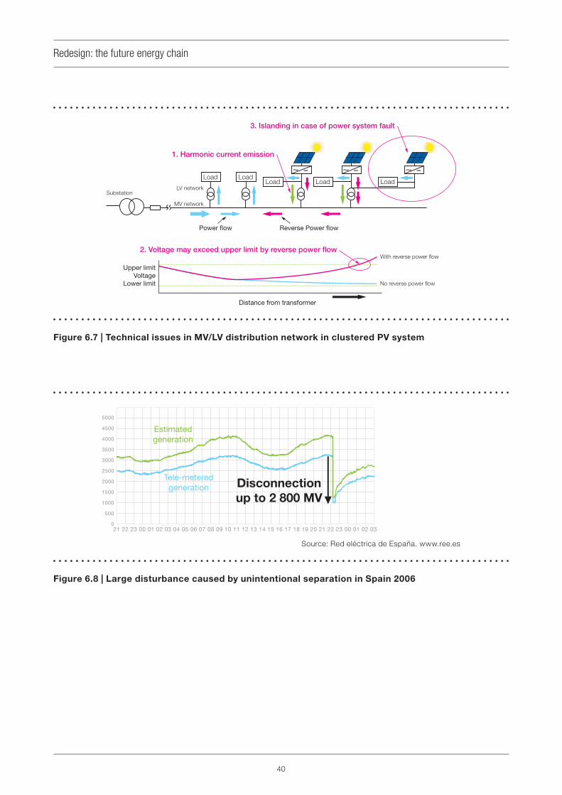
40
Redesign: the future energy chain
Figure 6.7 | Technical issues in MV/LV distribution network in clustered PV system
Figure 6.8 | Large disturbance caused by unintentional separation in Spain 2006
Source: Red eléctrica de España. www.ree.es

41
Redesign: the future energy chain
6.6.2 Systems approach issues
Sections 3 and 4 show the need for a systems
approach to each element of the current energy
chain (generation, transmission & distribution, end
use).
Section 5 implies that to go further energy
chain redesign is needed, which means more
coordination between the three elements of the
chain and a strong integration of information and
communication technologies with electronic,
automation & control and electrical technologies.
As an example, electricity distribution to groups
of houses might include, as illustrated in Figure
6.9, advanced metering, local renewable
generation (wind & solar), electricity storage,
electric vehicles, and a home energy
management system.
Figure 6.9 | Elements of an integrated distribution system
Substation

43
Section 7Critical success factors for implementing solutions
To conclude just before giving our recommenda-
tions, we list four critical success factors. Some
have been mentioned in relevant parts of previous
sections.
1) We need reference architectures for elec-
trical energy performance. Considerable
investment from the electrical engineer-
ing community is required for this.
To take the example of buildings, in different parts
of the world certifi cates for and ratings of the energy
performance of buildings are in use. Methodologies
have been developed based on thermal models
and calculations and give an estimate of what the
consumption of the building should be according
to its shell structure. However, these certifi cates
are more asset ratings (rating how the building was
built – insulation, double glazing) than operational
ratings (how the building is used). The energy
performance ratings do not today include any
electrical architecture and the related monitoring
and control architecture, although these are key to
the operational energy performance of a building.
Similarly, for the industrial example Sections 3.8
and 6.3.3 have shown that enormous progress
needs to be made, from optimizing individual
processes to optimizing whole production systems
on the basis of reference architectures. By
defi ning these architectures together with
the calculation and rating methodologies,
The IEC will be able to provide extremely high
added value.
2) The standardized solutions must go
beyond a simple product perspective
to provide a real application perspec-
tive. Preferred electrical-energy-effi cient
solutions should be described in stan-
dards and other IEC deliverables, to be
developed and widely promoted.
Development of standardization tools beyond
products and in an application-solution perspec-
tive would accelerate electrical energy effi ciency
implementation by all the actors in the value chain.
Factors 1 and 2, architectures and an application
perspective, are critical in particular because with-
out them the many present and future technologies
which can achieve effi ciency and decarbonization
cannot be effectively applied. Only these factors
can turn technologies into solutions.
3) Electrical energy effi ciency needs to
become visible on the political agenda
and in public incentive plans.
As a consequence of the political will to mitigate
climate change effects and implement energy
effi ciency plans, building codes have been modifi ed
and incentive plans (tax offset, preferred loans,
accelerated depreciations, …) are available in the
market. Similar steps are needed, but have not
yet been taken, for electrical energy performance,
notably of buildings and of industrial plants.
4) Specifi cally, the IEC’s electrical energy
effi ciency solutions should be made
politically visible.
Factors 3 and 4 in turn are critical so that society
may make the investments necessary to
achieve results, and so that consensual
solutions – the only globally effective ones –
may be applied.


45
Section 8Recommendations
8.1 Recommended evolution in the
IEC’s fundamental orientation
The IEC was historically safety and compati-
bility oriented.
We now have to take the lead in new areas
where integration of different approaches is
needed, such as energy effi ciency, productivity
and the environment.
More specifi cally for the current paper, the IEC now
has to tackle the energy challenge.
The IEC has historically concentrated on
product standards.
We now have to understand and base
our activity on a systems approach and
application-oriented global solutions.
Whether the IEC needs new TCs or needs to group
existing TCs together is uncertain and not within
the remit of the MSB. What is certain – and this
is the task of the MSB – is that the thinking must
start from the system and go on to the parts, and
not start from the individual products and possibly
progress to the system (as is the case today). This
must include both systems of new products (new
installations) and systems for retrofi tting whole
existing installations, with priority being given to the
latter in some areas. It must also include revisiting
existing product standards, where necessary,
when new systems standards have been prepared.
In summary, in Figure 8.1, the IEC should start
out by consideration of the application, and
then go on to write standards for the services
and products.
Figure 8.1 | Architecture for system-oriented standards development
Application (Solution)
Service
Technology
Service
Technology
Service
Technology
Pro
duct
Pro
duct
Pro
duct
Pro
duct
Pro
duct
Pro
duct
Pro
duct
Pro
duct
Pro
duct

46
Recommendations
The "applications" are defi ned by the market
according to its needs, and are not necessarily
limited to the IEC’s areas of competence. It is the
MSB’s task:
fi rst, to listen and put questions to the
market, in order to understand and describe
the applications (solutions) that the market
requires;
to determine which aspects of these solutions
are within the scope of the IEC;
to recommend that the IEC invite ISO and other
relevant standards development organizations
to cooperate in working out the solutions;
and finally to establish market priorities for
standardization of the “services” and products
needed by those solutions in the IEC’s
domain
The current paper, in Sections 3, 4 and 6, has
attempted to complete the fi rst two tasks for energy
effi ciency and CO2 emission reduction. Section 8
seeks to launch efforts towards accomplishing the
third and fourth.
On the basis of the proposed direction for
the evolution of the IEC, and the other facts
and arguments developed in this paper, the
MSB makes the recommendations contained
in Sections 8.2 and 8.3. Section 8.4 gives a
technology list generated during the production of
this paper which will be the basis of further work
in the MSB.
8.2 General recommendations
Rec. 8.2.1 – Required research and develop-
ment
The MSB recommends the IEC and its offi ce-
holders and experts to encourage progress to be
made in all the research and development projects
involving emerging technologies needed for
electrical energy effi ciency and decarbonization.
Rec. 8.2.2 – Political awareness and public
visibility
The MSB regards it as essential that the IEC’s
energy effi ciency solutions become visible on the
political agenda and in public incentive plans.
It recommends all relevant actors in the IEC
community worldwide to use every opportunity to
raise political awareness and the public visibility of
IEC’s standards for this purpose.
Rec. 8.2.3 – Liaison with international orga-
nizations
The MSB recommends the IEC to strengthen its
ties with the following organizations in particular:
The International Energy Agency (IEA), in the
areas of statistics, indicators, benchmarking
information in relation to the work done as part
of Implementing Agreement (IA) on Effi cient
Electrical End-Use Equipment (4E)
The Asia-Pacifi c Partnership for Clean
Development and Climate (APP) Peer Review,
for best practices in development, diffusion
and transfer of clean and effi cient technologies
in power generation
The World Energy Council
The United Nations’ Intergovernmental Panel
on Climate Change (UN IPCC)
Rec. 8.2.4 – Cooperation with regulatory and
political authorities
In the context of Recommendations 8.2.2 and
8.2.3, the MSB recommends the IEC to consider
developing closer contacts with regulatory and
political authorities in order to promote electrical-
energy-effi cient solutions.
Rec. 8.2.5 – Technology Watch and standard-
ization Road Maps
The MSB will put in place a permanent Technology
Watch function for electrical energy effi ciency (EEE)
and carbon dioxide emissions reduction (Decarb).

47
Recommendations
An ongoing task of this function will be to create
and update Road Maps showing the current and
foreseeable development of various technologies
available for EEE/Decarb and the corresponding
timetables for standardization.
Rec. 8.2.6 – Reference architectures for elec-
trical energy performance
The MSB recommends the IEC to develop standards
giving reference architectures for electrical energy
performance. Architectures will be needed for the
different domains, such as buildings, services,
industry and so on. Considerable investment
from the electrical engineering community will be
required and must be planned for.
Rec. 8.2.7 – Industry’s urgent need for EEE
Industry uses almost half of all the electricity
produced. It is therefore particularly vital for
this area that reference-architecture and best-
practice standards should be rapidly developed
and implemented. These standards and other
publications should promote advances in the
following major areas: regulatory and fi nancial
incentives to encourage EEE (on the price of
electricity, for example); subsidies and other
incentives for new energy-/carbon-effi cient capital
investment; tools for benchmarking against
best practices; facilitating the implementation of
innovative technologies.
Rec. 8.2.8 – Use of an applications rather
than product-oriented approach
The MSB recommends the SMB to ensure that
the standards giving preferred electrical-energy-
effi cient solutions go beyond a simple product
approach and consistently adopt a real application
perspective. This will involve keeping in mind the
global effects desired (e.g. for EEE), the functioning
of the systems in which the products are integrated
in practice, and in some cases revisiting current
product standards once new standards for
systemic solutions (“service” in terms of Figure 8.1)
are in place.
Rec. 8.2.9 – Options and rules for connection,
stability, intelligence and effi ciency of elec-
tric grids
The MSB recommends the IEC, in close
cooperation with CIGRÉ, NIST and other relevant
organizations, to develop rapidly a full and detailed
set of standards giving minimal performance rules
and a full set of options for the operation of grids.
This should be conceived as a part of the set of
standards needed by “smart grids”.
The standards should cover connection (especially
of fl uctuating sources), stability, “intelligence”
(required functions of the IT applications controlling
the grid), and minimum systemic effi ciency as well
as how to measure it. Aspects to deal with include
balancing demand and generation, power quality,
harmonic current emissions, voltage fl icker, voltage
fl uctuation and islanding prevention. The standards
should allow for the necessary differences in
approach and choices made in different countries;
thus some of the resulting publications may be
non-normative.
In order to facilitate implementation, the MSB
further recommends the IEC and cooperating
organizations to organize a public symposium
on what the necessary standards and other IEC
publications on the “smart grid” should contain.
Rec. 8.2.10 – Best practices for electrical
energy management
The MSB recommends the IEC to develop
standards for best practices in electrical energy
management. These standards should be
specifi cations for the technical aspects of electrical
energy management. They should not be based
on products or individual installations but on the
whole systems involved, and be built around the
services to be delivered and the goals for energy
effi ciency and GHG reduction.

48
Recommendations
8.3 Detailed recommendations
Below are recommendations in various individual
areas (mostly involving mature technologies) which
the MSB has identifi ed as advancing EEE and
decarbonization.
Rec. 8.3.1 – Product standards suitable for a
co-generation environment
The MSB recommends the SMB to ensure that
all product energy-effi ciency standards take
into account the possible use of the product in
an environment of co-generation. This may for
example involve measuring effi ciency partly in
function of the source, the switching, the metering
or the quality of the power supplied to the product.
Rec. 8.3.2 – Solar thermal power generation
The MSB recommends the SMB to examine the
opportunity of developing standards on solar
thermal power generation.
Rec. 8.3.3 – Energy architecture for buildings
The MSB recommends the SMB to develop
standards for an energy architecture for
buildings, including control, monitoring and rating
methodologies, as tools for electrical energy
effi ciency implementation.
Rec. 8.3.4 – Energy-effi ciency measurement
methods for industry
The MSB recommends the SMB to develop
standards for measurement methods in industry,
needed for benchmarking, energy audits,
assessing compliance with regulations, etc.
Rec. 8.3.5 – Electric-vehicle charging infra-
structure
Insofar as they are not already under way, the MSB
recommends the SMB to develop standards for
the infrastructure for charging electric vehicles and
its connections to the vehicles.
Rec. 8.3.6 – Micro-grids
The MSB will rapidly establish a technology watch
and defi ne a road map (see Rec. 8.2.5) for the
elements and systems involved in micro-grids,
including when each area is likely to be ripe for
standardization.
8.4 Technology list
In the process of the data gathering and discussion
which have led to this paper, the MSB members
identifi ed the need for clarity in the various
technologies and political or social processes
necessary for EEE, as well as for their prioritization.
The present section is the initial result of the inputs
received so far.
Much work remains to be done to complete, clarify
and disambiguate the list below, and even more to
make coherent proposals on priorities. The list is
therefore not intended to condition the current
paper but to provide input for future steps.
Solar energy
Solar technology
Solar photovoltaic
PV : nano-3D-structured cells
Solar thermal
PV (the rest)
Nuclear power
Nuclear power
High-effi ciency new-generation nuclear power-
safety
Extended-licence nuclear power-safety
Marine, Hydro and Geothermal
Wave/ocean power
Tidal generators
Wave generators
Hydro-electric power
Geothermal power

49
Recommendations
Wind power
Micro-wind power generation
Wind turbines
High-power wind turbines
Large-scale offshore wind (transfer & storage)
Heat
Integrated Coal Gasifi cation
Combined Cycle
High-effi ciency coal thermal power generation
CCS
CCS (carbon capture & storage)
Carbon capture
Carbon storage
Fuel cells and Heat pump
Stationary fuel cells, utility-scale
Stationary fuel cells, residential/building-scale
Solid-oxide fuel cells (duplication with above ?)
Molten-carbonate fuel cells (duplication with
above ?)
Proton-exchange membrane fuel cells
(duplication with above ?)
Heat pumps
Storage
Storage of electrical energy
High-capacity battery technologies
Magnetic storage in superconducting coils
Capacitors
Flywheel energy storage
Compressed-air and electricity storage
High-power permanent magnet motors
Battery for EV (electric vehicles), PHEV (hybrid)
Energy transmission and distribution
Ultra High Voltage transmission AC
High Voltage transmission DC
New types of conductors
Gas-insulated lines (GIL)
High-current composite conductors
High-temperature superconductors
Low-voltage DC supply
Grid
Micro-grid and decentralized system
Interface with grid
Smart Grid
Smart Home with Heating and Cooling
Demand response
Volt/var optimization
Sectoral approach
Low-energy-consumption buildings / Building
energy management systems
Intelligent Transport System
Lighting by LED
Effi cient appliances
Effi cient offi ce equipment
Inert anodes for aluminium smelters
Reluctance motors
Energy-saving technologies
Load balancing
High-effi ciency inverters
High-effi ciency fi ltering of harmonics
Reduced standby losses
Automated sensors and controls
Adaptive presence detection
Weather forecasting
Recycling of electrical components

50
Recommendations
High-level verifi cation
Predictive maintenance (e.g. of transformers)
Calibration of instruments
Management and process
Road Map of innovative technology
Administration of energy-saving management
Introduce Top Runner method (JP) into white
goods
Education and notifi cation activity (publicity)
Energy Conservation Centre in each sector
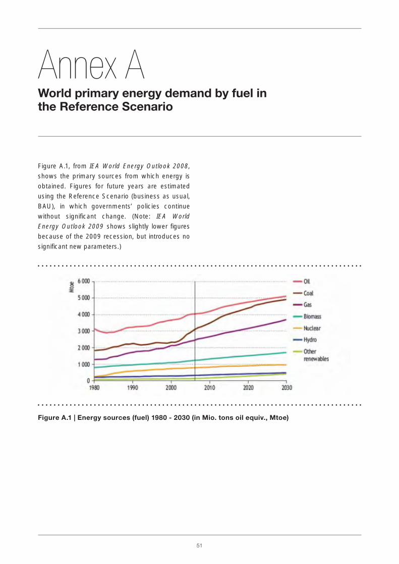
51
Figure A.1, from IEA World Energy Outlook 2008,
shows the primary sources from which energy is
obtained. Figures for future years are estimated
using the Reference Scenario (business as usual,
BAU), in which governments’ policies continue
without signifi cant change. (Note: IEA World
Energy Outlook 2009 shows slightly lower fi gures
because of the 2009 recession, but introduces no
signifi cant new parameters.)
Annex A World primary energy demand by fuel in the Reference Scenario
Figure A.1 | Energy sources (fuel) 1980 - 2030 (in Mio. tons oil equiv., Mtoe)

52
If nothing is done, the situation will get worse.
Without a change in policy, the world is on
the path towards a rise in global average
temperature of 6 °C. According to the UN
IPCC, the consequences of such a rise would
be “signifi cant change in all aspects of life and
irreversible change in the natural environment”.
IEA World Energy Outlook 2008 assesses the
implications for the energy sector of efforts to put
the world on to a different trajectory, by means
of a 550 Policy Scenario, in which greenhouse
gas concentration is stabilized at 550 ppm CO2-
equivalent with a temperature rise of about 3 °C,
and of a 450 Policy Scenario which results in a
2 °C increase. These scenarios are illustrated in
Figure B.1 (Note that IEA World Energy Outlook
2009 omits the 550 Scenario.)
Annex B Scenarios for greenhouse gas emissions and temperature rise
Figure B.1 | Policy scenarios for greenhouse gas emission reduction
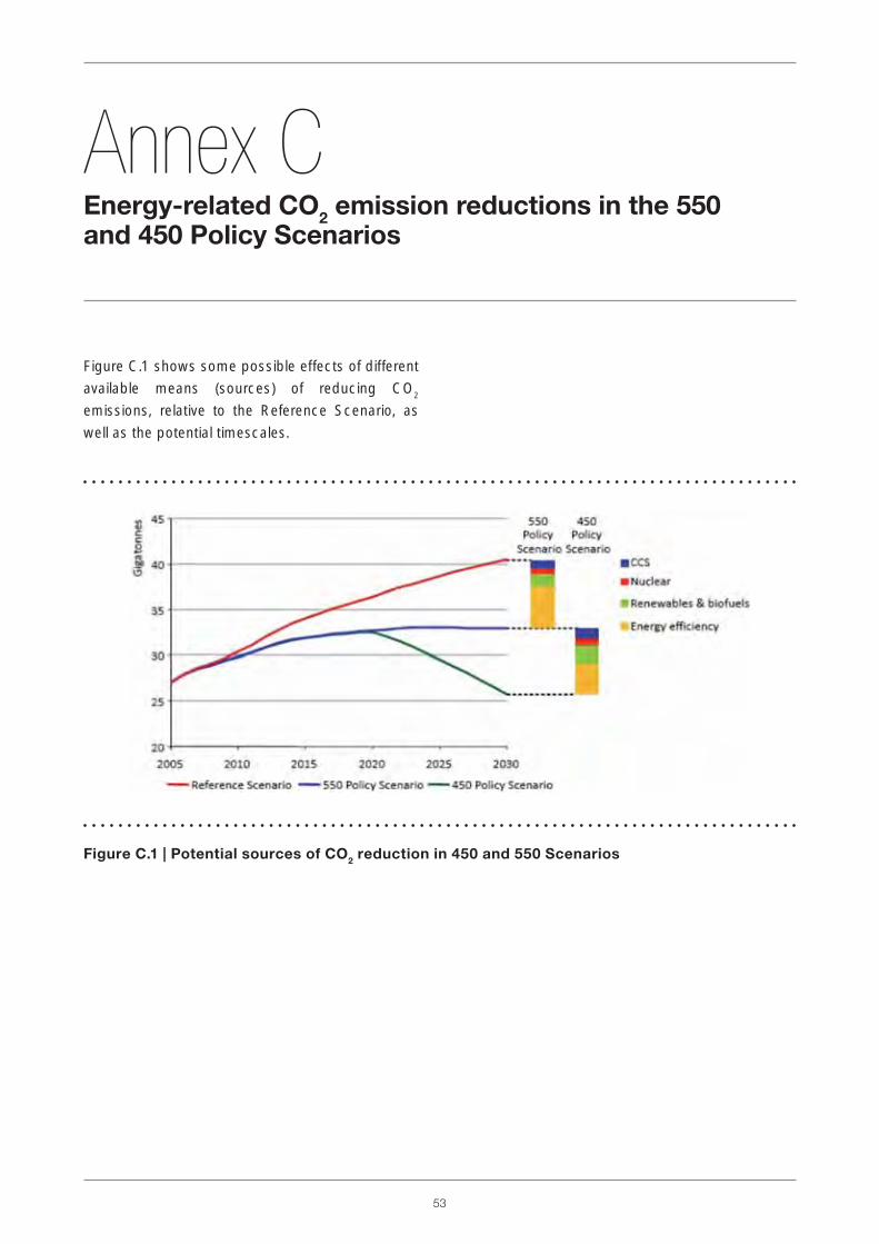
53
Figure C.1 shows some possible effects of different
available means (sources) of reducing CO2
emissions, relative to the Reference Scenario, as
well as the potential timescales.
Annex C Energy-related CO
2 emission reductions in the 550
and 450 Policy Scenarios
Figure C.1 | Potential sources of CO2 reduction in 450 and 550 Scenarios

54
Annex DSystematic evaluation of effi ciency and CO
2 reduction
The concept shown in Figure D.1 can be applied to
all electrical energy systems, i.e. power systems, lo-
cal generation, generation in the home, independ-
ent generating plants, transmission, distribution
and applications. Renewable energies such as solar
photovoltaic, wind power, mini-hydro systems, ge-
othermal power, solar thermal power, heat pumps
and large-scale hydropower 6 are also included.
6 See Section 4.1, Renewable energies (RE).
Figure D.1 | Schema for measurement and evaluation of electrical energy effi ciency

55
Systematic evaluation of effi ciency and CO2 reduction
Below a step-by-step approach is given. See also
Section 3.2, The current electrical energy chain.
D.1 Generation
CO2 emissions (GHG emissions) largely depend
on power generation methods. Therefore it is
desirable to defi ne the CO2 indicator for generation
methods and input energy and, when evaluating
electrical energy effi ciency, to begin with the
processes in the cream-coloured ovals in Figure
D.1, as follows (the result will infl uence every stage
after generation):
Indicator of CO2 at generation =
CO2 / IE (Input Energy)
The effi ciency of generation independently of CO2
is the amount of electricity per unit of input:
Indicator of effi ciency of generation =
GE (Generated Energy) / IE
The effi ciency of steam power generation is
described by the IEA 7.
D.2 Transmission
The effi ciency of transmission depends on
transmission loss:
Indicator of effi ciency of transmission =
TE (Transmitted Energy) / GE
D.3 Distribution
The effi ciency of distribution is determined by
controlling load changes, the structure of the grid
system to end-users, and management of the grid
system, including smart grid. Considering total
losses, the effi ciency can be described as:
Indicator of effi ciency of distribution =
DE (Distributed Energy) / TE
7 Worldwide Trends in Energy Use and Effi ciency, IEA.
D.4 Applications
Applications should be dealt with in all the
sectors mentioned in this paper (e.g. buildings/
services, industry), at the relevant level of detail.
For each sector CO2 reductions through changed
behaviour (see Sections 2.3.1, 2.3.5 and 3.1) and
“electrifi cation” (see Section 2.3.3) should be
taken into account, in addition to improvements in
electrical energy use by best available technology
(BAT).
D.4.1 Industry
The industrial sector includes steel, cement, power
generation, chemical, pulp and paper, among
others 8. Each has various characteristic processes,
and the concepts of this section may be useful in
analyzing the electrical energy aspects of those
processes.
D.4.2 Buildings: commercial and service
buildings (incl. offi ces)
Buildings should be separated into a commercial/
service sector and a residential sector. There
are two methods in the fi rst sector to improve
effi ciency: to increase the effi ciency of pieces of
equipment such as air-conditioners, lighting or
offi ce machines; and to improve the management
and the usage schedule of that equipment 9.
D.4.3 Buildings: residential sector
There is a method for the residential sector in Japan
called the “Top-runner method”, which encourages
improvements in equipment so as to use BAT 9.
8 Japan Energy Conservation Handbook 2008, The Energy
Conservation Center, Japan.9 See for example Section 3.7, Use of electricity in buildings.
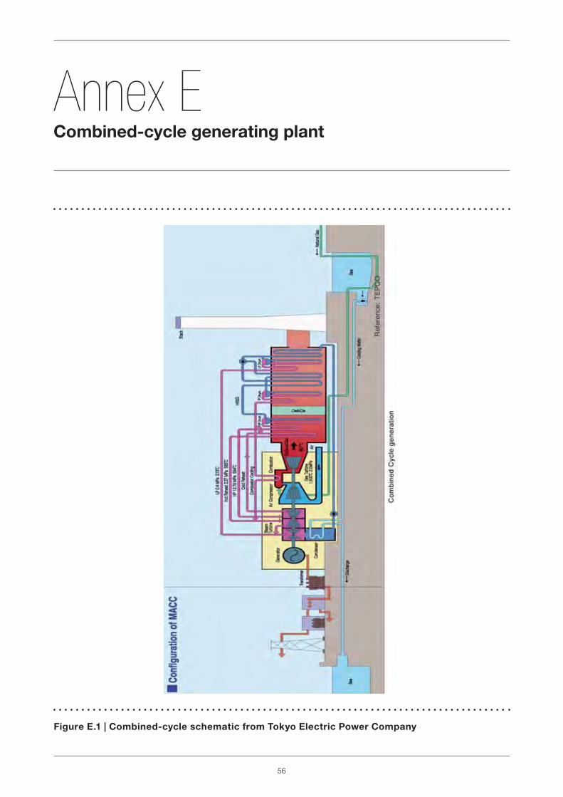
56
Annex ECombined-cycle generating plant
Figure E.1 | Combined-cycle schematic from Tokyo Electric Power Company

57
In Figure F.1, a schematic is provided of the
IGFC technology under fi eld test, mentioned in
Section 3.5.
Annex F Integrated coal gasifi cation and fuel cell, IGFC
Figure F.1 | Integrated coal-gasifi cation/fuel-cell combined cycle (IGFC)

58
From UNEP, Buildings and climate change 2007; source IEA 2002
Energy consumption in residential and tertiary
buildings represents around 40 % of total
consumption and is targeted for signifi cant potential
savings through energy effi ciency in the coming
decade.
In the residential sector (household) in a given
country several segments can be differentiated
(fl ats/apartments, private houses, condominiums,
…). However, in a global perspective, Figure G.1
shows that energy use and consumption is strongly
driven by and correlated with income. The more
income grows, the more electricity is used as an
energy source.
Annex G Analysis of energy use in buildings – some fi gures
Figure G.1 | Relationship between income and residential energy use

59
Analysis of energy use in buildings – some fi gures
The non-residential buildings segment covers a
large scope of applications such as offi ce buildings,
hospitals, commercial malls, train stations, etc.
Some of these contain heavy processes such as
data centres. The relative energy use according to
type is shown in Figure G.2.
ICT equipment is increasing exponentially in both
homes and offi ces. Ten years ago this was almost
non-existent in residential facilities. It can now
represent up to 1 000 kWh per year in developed
countries, with up to 30 % consumed in standby
mode (source: France ADEME 2008).
Analysis by usage gives a good framework.
However, from one country to another notable
differences exist, as shown in Figure G.3, so that
for a useful benchmark it is important to have
consumption data by usage available for a given
country. Even though technology allows economic
measurement of consumption by usage, this is
seldom in place, and data are estimates rather than
true measurements.
From UNEP, Buildings and climate change 2007; source Atlas 2006
Figure G.2 | Relative non-residential-building energy use by type of building

60
Analysis of energy use in buildings – some fi gures
Life-cycle analysis demonstrates how critical energy
effi ciency is, throughout the lifetime of buildings
(see Figure G.4). Optimizing energy usage by
allowing only the necessary energy and only when
necessary is key during the whole operational life of
the buildings.
Figure G.4 | Energy use by stage in the life cycle of a building
Figure G.3 | Country comparison of uses of energy in buildings
From UNEP, Buildings and climate change 2007
Building & Environment, Vol. 32, No. 4, pp. 321-329 (1997)

61
Analysis of energy use in buildings – some fi gures
In non-residential buildings electricity represents
around 50 % of energy used, and furthermore is
key for control of other fuel usage such as that for
heating. Figure G.5 shows numbers for the US,
Figure G.6 for France.
Figure G.5 | Energy use breakdown in US commercial buildings: electricity is almost half of all
end use, but more than 75 % of primary energy
Figure G.6 | Relative changes 1973-2005 in electricity consumption of French households,
by type of use (1973 = 100)

62
There are several ways to classify the processes
in industry. For the development of EEE one
approach is to take machinery that is used for the
conversion of electrical energy into other forms
of energy as the basis for the classifi cation. The
level of abstraction of the classifi cation scheme
must be high enough that the list of processes
is manageable, but not so high as to prevent the
scheme being used to formulate best practices
or give practical guidelines. The classifi cation
scheme described by the diagram below, provided
as an example, places machines for working and
conveying solid, liquid and gaseous material into a
hierarchy.
Annex H Example of a reference architecture for material handling

63
Annex JGeneration IV nuclear energy
Figure J.1 | Supercritical Water-Cooled Reactor (SCWR)
Reference: Gen-IV International Forum

64
Generation IV nuclear energy
Figure J.2 | Transition in generations of nuclear energy production
Reference: Gen-IV International Forum

65
Annex KCarbon capture and storage
Figure K.1 | Options for carbon capture and storage, CCS
Reference: IEA Greenhouse Gas R&D Programme

66
Annex LSensitivity analysis of CO
2 reduction measures
In a business-as-usual scenario, shown as BAU
in Table L.1 below, CO2 emissions due to
electricity generation would almost triple by
2050.
A fi rst scenario could limit emissions to
less than doubling CO2 by 2050. Table L.2
below (for 2030) and Table L.3 (for 2050) show
the improvements possible in green and yellow:
in order, from top to bottom, end-use effi ciency
improvements of 30 %, increase of renewable/
nuclear generation to 30 %, reduction of T&D
losses from 9 % to 7 %, and a 5 % improvement in
generation effi ciency. After each improvement the
new totals (energy used, CO2 emitted) are shown
on a new line where they are different.
Table L.1 | Electricity generated/used and CO2 emitted in business-as-usual, 2010-2050
Generated
electricity
TWh
Renewable
/ Nuclear
electricity
TWh
Electricity
from fossil
fuel
TWh
Centralized
hydro
TWh
Centralized
generation
TWh
Decentralized
generation
TWh
T&D losses
TWh
Final electricity
consumption
TWh
CO2
emissions
Gt CO2
Hypothesis
of BAU
2.5 %
growth
per year
20 % share fl at Flat at 9 %0.54 kg
per kWh fl at
2010 Ref 20 000 4 000 16 000 3 200 19 200 800 1 800 18 200 10.8
2030 BAU 33 000 7 000 26 000 5 600 31 600 1 400 2 970 30 000 17.8
2050 BAU 54 000 11 000 43 000 8 800 51 800 2 200 4 860 49 100 29

67
Sensitivity analysis of CO2 reduction measures
Table L.2 | Effects of end-use effi ciency, 30 % renewables and 2 % T&D loss reduction, 2030
Table L.3 | Effects of 30 % end-use effi ciency/renewables and 2 % T&D loss reduction, 2050
Generated
electricity
TWh
Renewable
/ Nuclear
electricity
TWh
Electricity
from fossil
fuel
TWh
Centralized
hydro
TWh
Centralized
generation
TWh
Decentralized
generation
TWh
T&D
losses
TWh
Final electricity
consumption
TWh
CO2
emissions
Gt CO2
2010 Ref 20 000 4 000 16 000 3 200 19 200 800 1 800 18 200 10.8
2050 BAU 33 000 7 000 26 000 5 600 31 600 1 400 2 970 30 000 17.8
Less 30 %EE end use reduction -5 500 -2.9
2030 after EE end use 24 500
30 % renewable(16 % H &14 % DG)
Renewable effect 27 000 10 200 16 800 5 600 22 400 4 600 24 500 -1.7
T&D losses 27 000 10 200 16 800 5 600 22 400 4 600 2 430 24 500
7 % T&D losses instead of 9 %
T&D losses reduction
effect-540 -0.3
5 % improvement in generation
effi ciency
Generation effi ciency
improvment-1.45
2030 SC1 26 400 10 200 16 800 5 600 22 400 4 600 1 890 24 500 11.5
Generated
electricity
TWh
Renewable
electricity
TWh
Electricity
from fossil
fuel
TWh
Centralized
hydro
TWh
Centralized
generation
TWh
Decentralized
generation
TWh
T&D
losses
TWh
Final electricity
consumption
TWh
CO2
emissions
Gt CO2
2010 Ref 20 000 4 000 16 000 3 200 19 200 800 1 800 18 200 10.8
2050 BAU 54 000 11 000 43 000 8 800 51 800 2 200 4 860 49 100 29
Less 30 %EE end use reduction -14 700 -8
2050 after EE end use 37 800 34 400
30 % renewable (16 % H & 14 % DG)
Renewable effect 37 800 16 400 21 400 8 800 30 200 7 600 34 400 -2.9
T&D losses 37 800 16 400 21 400 8 800 30 200 7 600 3 400 34 400
7 % T&D losses instead of 9 %
T&D losses reduction
effect-760 -0.4
5 % improvement in generation
effi ciency
Generation effi ciency
improvment-1.7
2050 SC1 37 000 16 400 21 400 8 800 30 200 7 600 2 640 34 400 16.1
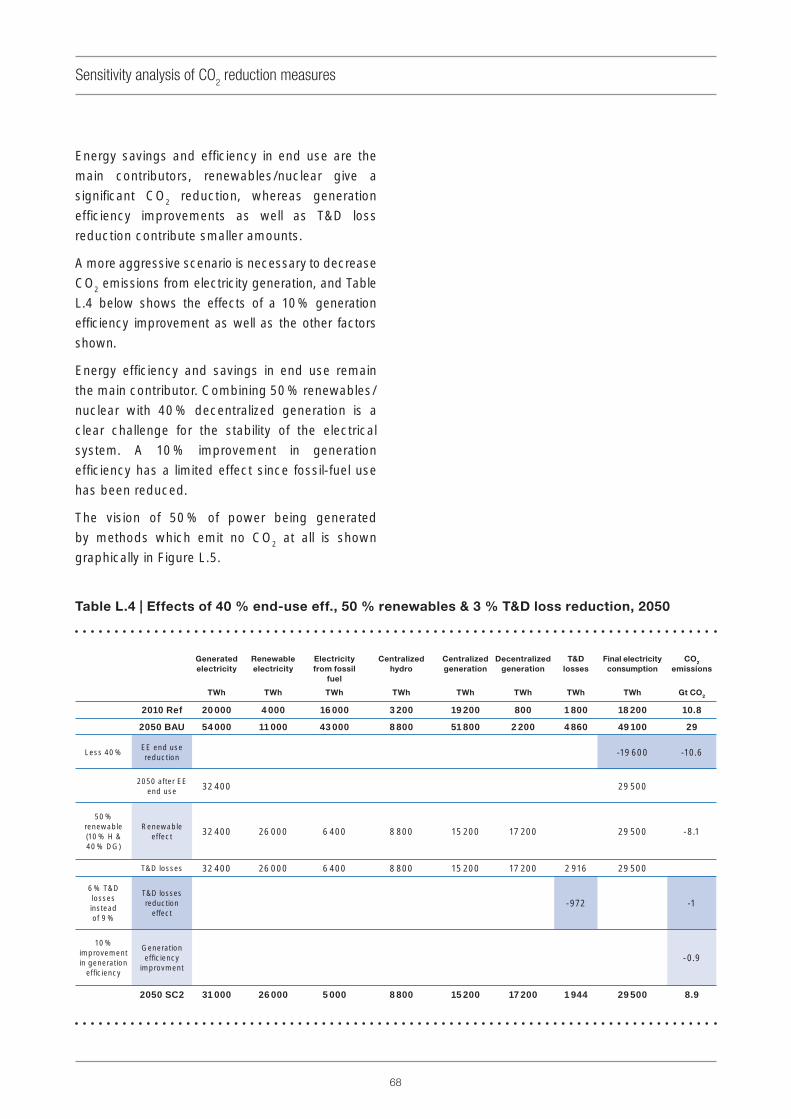
68
Sensitivity analysis of CO2 reduction measures
Energy savings and effi ciency in end use are the
main contributors, renewables/nuclear give a
signifi cant CO2 reduction, whereas generation
effi ciency improvements as well as T&D loss
reduction contribute smaller amounts.
A more aggressive scenario is necessary to decrease
CO2 emissions from electricity generation, and Table
L.4 below shows the effects of a 10 % generation
effi ciency improvement as well as the other factors
shown.
Energy effi ciency and savings in end use remain
the main contributor. Combining 50 % renewables/
nuclear with 40 % decentralized generation is a
clear challenge for the stability of the electrical
system. A 10 % improvement in generation
effi ciency has a limited effect since fossil-fuel use
has been reduced.
The vision of 50 % of power being generated
by methods which emit no CO2 at all is shown
graphically in Figure L.5.
Table L.4 | Effects of 40 % end-use eff., 50 % renewables & 3 % T&D loss reduction, 2050
Generated
electricity
TWh
Renewable
electricity
TWh
Electricity
from fossil
fuel
TWh
Centralized
hydro
TWh
Centralized
generation
TWh
Decentralized
generation
TWh
T&D
losses
TWh
Final electricity
consumption
TWh
CO2
emissions
Gt CO2
2010 Ref 20 000 4 000 16 000 3 200 19 200 800 1 800 18 200 10.8
2050 BAU 54 000 11 000 43 000 8 800 51 800 2 200 4 860 49 100 29
Less 40 %EE end use reduction -19 600 -10.6
2050 after EE end use 32 400 29 500
50 % renewable (10 % H & 40 % DG)
Renewable effect 32 400 26 000 6 400 8 800 15 200 17 200 29 500 -8.1
T&D losses 32 400 26 000 6 400 8 800 15 200 17 200 2 916 29 500
6 % T&D losses instead of 9 %
T&D losses reduction
effect-972 -1
10 % improvement in generation
effi ciency
Generation effi ciency
improvment-0.9
2050 SC2 31 000 26 000 5 000 8 800 15 200 17 200 1 944 29 500 8.9

69
Sensitivity analysis of CO2 reduction measures
Figure L. 5 | Schematic evolution towards 50 % CO2-free generation in 2050

70
Annex MThe DESERTEC project

®
InternationalElectrotechnicalCommission
T +41 22 919 02 [email protected]
3 rue de VarembePO Box 131CH-1211 Geneva 20Switzerland
® Registered trademark of the International Electrotechnical Commission. Copyright © IEC, Geneva, Switzerland 2010.
ISBN 978-2-88912-890-7
CHF 50.-
IEC
WP
Ener
gy C
halle
nge:
2010
-09(
en)


![Security Testing: A Survey - White Rose Research Onlineeprints.whiterose.ac.uk/95628/1/book_chapter_sectesting.pdf · ISO/IEC 25010 [68] standard that revises ISO/IEC 9126 and introduces](https://img.pdfslide.us/doc/110x75/5e7b94ca2488d5364811dae5/security-testing-a-survey-white-rose-research-isoiec-25010-68-standard-that.jpg)