Embed Size (px)
Citation preview

PROCEEDINGS of CHEF 2013
EndoTOFPET-US - A Miniaturised Calorimeter forEndoscopic Time-of-Flight Positron EmissionTomography
Milan Zvolský∗ on behalf of the EndoTOFPET-US CollaborationDESY Hamburg, GermanyE-mail: [email protected]
In the scope of the EndoTOFPET-US project, a novel multimodal device for Ultrasound (US) En-doscopy and Positron Emission Tomography (PET) is being developed. The project aims at de-tecting and quantifying morphologic and functional markers and developing new biomarkers forpancreas and prostate oncology. Exploiting the Time-of-Flight (TOF) information of the gammarays allows for a more sensitive, more precise and lower radiation-dose imaging and interventionon small internal structures. The detection of the gamma rays is realised with the help of scintilla-tor crystals with Silicon Photomultiplier (SiPM) read-out, aiming at a coincidence time resolutionof 200 ps and a spatial resolution of 1 mm. For the endoscopic detector, digital SiPMs are utilisedfor the first time in an instrument planned for clinical applications. The functionality of the instru-ment as well as the challenges that accompany the high level of miniaturisation of the endoscopicdetector and the asymmetric and variable geometry of the system, are presented. The demands onthe system involve the fields of scintillating crystals, ultra-fast photon detection, highly integratedelectronics, system integration as well as image reconstruction. The design of the system, thestatus of the the single detector components and the integration plans are discussed.
Calorimetry for High Energy Frontiers - CHEF 2013,April 22-25, 2013Paris, France
∗Speaker.
433

EndoTOFPET-US Milan Zvolský
1. Introduction
Inspired by our expertise in high-energy physics calorimetry1, such as the CMS calorimeter,which involves scintillation crystals, silicon photomultipliers and front-end electronics, we aim atcommissioning a miniaturised calorimeter for endoscopic positron emission tomography (PET).The prospect of the EndoTOFPET-US project 2 [1] is the development of a novel multimodalimaging device for ultrasound (US) and time-of-flight PET for detecting and quantifying morpho-logic and functional markers as well as establishing and testing new biomarkers for pancreas andprostate carcinoma [2, 3]. At the same time this tool is supposed to provide an intra-operative guidefor prostate and pancreas surgery. This is achieved by mounting a PET detector head on a com-mercially available US endoscope in combination with an outer detector plate located next to thebody. Radio-labelled biomarkers are injected into the patient and undergo β+ decay, leading to twoback-to-back photons with an energy of 511 keV each. These photons are detected in coincidenceby the endoscopic and the external detector.
The main reason for exploiting the endoscopic imaging approach is that the organ under studyis surrounded by organs with a high metabolic uptake, such as liver, duodenum and gall bladderin case of the pancreas, and the bladder in case of the prostate. If one part of the PET detector islocated in the direct proximity of the organ under study and provides time-of-flight (TOF) informa-tion, one is able to narrow down the region of interest and thus significantly reduce the backgroundfrom neighbouring organs. Pancreas cancer is practically symptom-free during its early stages sothat it often already spread to other organs when discovered, leading to highly adverse 5-year sur-vival rates of around 8 % [4]. Prostate cancer, on the other hand, is among the most frequentlydiagnosed cancer for males, whereas survival rates are very good if diagnosed and treated suffi-ciently early. Being able to produce highly-resolved and low-noise functional (metabolic) images,fused with the anatomical information from the ultrasound transducer, allows for an earlier detec-tion and thus a higher healing probability of prostatic and pancreatic carcinoma.
The challenges that come along with building and commissioning such a detector device in-volve the extreme miniaturisation of the endoscopic PET head and highly integrated electronicsas well as the ultra-fast detection of photons in order to allow TOF measurements. Another chal-lenge is the image reconstruction for a limited-angle, free-hand PET detector that incorporates TOFinformation and provides on-line images with a design spatial resolution of 1 mm FWHM.
The aim of this project is to achieve a coincidence time resolution (CTR) of 200 ps FWHMwhich corresponds to a flight distance of approximately 3 cm. This is realised by utilising fastinorganic scintillator crystals, read out by ultra-fast silicon photomultipliers (SiPMs). SiPMs arephoton counting devices consisting of avalanche photodiodes operated in Geiger mode. Due totheir high gain they are sensitive to single-photon hits which is crucial for the envisaged CTR.
1The project partners are involved in collaborations such as the CMS calorimeter at the Large Hadron Collider(LHC) as well as the CALICE calorimeter for the International Linear Collider (ILC).
2The EndoTOFPET-US consortium consists of six universities, three hospitals as well as three companies. Seehttps://endotofpet-us.web.cern.ch/endotofpet-us/partners.html for a list of the project part-ners.
434

EndoTOFPET-US Milan Zvolský
2. Detector Design
2.1 Endoscopic Detector
In case of the prototype for the prostate case, the endoscopic PET detector is mounted on acommercially available ultrasound (US) endoscope (Hitachi EUP-U533). Due to the immediatevicinity of the detector to the organ under study, a high granularity is crucial in order to guaranteeexcellent spatial resolution. On the other hand, due to anatomical constraints, the PET head ex-tension must not exceed a volume of 23× 23× 40 mm3. On this volume, 324 detector channelsare placed: The detector consists of two matrices of 9×18 LYSO scintillator crystals from Proteuswith a size of 0.71×0.71×15 mm3 coupled to multi-channel digital SiPMs (md-SiPMs). Besides,the PET head extension houses the printed circuit board (PCB) as well as a cooling system andpossibly an electromagnetic tracking sensor, as can be seen in Fig. 1 (left). The endoscope for thepancreas case will be equipped with only one 9×18 crystal matrix.
Commercial Ultrasound (US) EndoscopeHitachi EUP-U533
PET HeadExtension
Water Cooling
md-SiPM PCB
2 Matrices of 9x18 Crystals
EM Tracking Sensor
md-SiPM Array
US Transducer
Figure 1: (left) Sketch of the design of the endoscopic ultrasound endoscope with the PET head extension.The inlet shows a zoom of the PET head, depicting the crystal matrices, md-SiPMs, PCB and cooling pipes.(right) CAD drawing of the current design of the external PET detector plate.The green plate underneaththe detector depicts the front-end boards. Above that, an aluminium plate (grey) houses the cooling andmechanically fixes the printed circuit boards (PCBs) on which the ASICS are mounted. The uppermoststructure symbolises the crystal matrices and the SiPM arrays.
2.2 External Detector Plate
The photons impinging on the endoscopic probe are detected in coincidence with an externaldetector plate which is located in the direct proximity of the patient. It is divided into 256 modules,each of which is assembled from a matrix of 4× 4 LYSO crystals from Crystal Photonics Inc.(CPI) that are separated by 100 µm thick 3M Vikuiti reflector foil. The crystals have a size of3.5× 3.5× 15 mm3, leading to a total number of 4096 single crystals on an area of 23× 23 cm2.Each crystal matrix is read out by an array of 4× 4 discrete analog SiPMs. Dedicated fast 64-channel application specific integrated circuits (ASICs) are mounted directly on the detector platein order to optimise the timing properties. Besides, an aluminium plate with an integrated waterpipe will be embedded in the detector housing in order to cool the front-end boards (FEBs) andASICs, c.f. Fig. 1 (right). The detector will be held by a robotic arm that allows for the movementin concordance with the endoscope movement as well as the precise tracking of its position.
435

EndoTOFPET-US Milan Zvolský
2.3 Data Acquisition (DAQ)
The external plate houses eight front-end boards (FEBs), each of which accommodates eight64-channel ASICs as well as a field programmable gate array (FPGA). The signals from the detec-tor channels are transferred to the ASICs via flexible printed circuits. The FEB FPGA concentratesthe digital output of the ASICs and transmits them to the DAQ card via a HDMI cable, c.f. Fig. 2(left). The maximum event rate is 160 kHz per channel and 10 MHz per ASIC [5] which cov-ers the expected event rate of 40 MHz. The events from the probe’s md-SiPMs are read out bya small FPGA which is mounted directly on the probe. The maximum event rate for the probe is625 kHz. The DAQ system uses a PCIe card, installed at the same bedside workstation that alsohosts the computers for the image reconstruction, tracking and slow control. The card merges thedata from the external plate and the probe and performs a coarse event selection of coincidencecandidates, using a 12.5 ns wide coincidence window. This selection reduces the event rate to 350kHz while ensuring that no interesting events are discarded. The DAQ software then extracts theprecise energy and time information from the events, reconstructs in-detector Compton scatteringand performs the final coincidence sorting. With a rate of less than 50 kHz the data is then pro-cessed to the image reconstruction software in list-mode format, along with the information fromthe ultrasound as well as the tracking data of probe and plate. The steps of the event processingand DAQ chain are sketched in Fig. 2 (right).
FEB 1FEB 5
FEB 2FEB 6
FEB 3FEB 7
FEB 4FEB 8
dSiPM
ASIC ASIC ASIC ASIC
ASIC ASIC ASIC ASIC
800 Mbit/s
FPGA
DAC
Front-End Board
External PET plate
Probe
Data Acquistion Card
400 Mbit/sFPGA
Figure 2: (left) Data acquisition (DAQ) system components [5]. (right) Flowchart of the DAQ and eventprocessing chain.
2.4 Software and Hardware Integration
It is foreseen that two separate computers are housed by a bedside cart, one of which is respon-sible for the DAQ as well as the image reconstruction. A second PC is responsible for the tracking,communication and visualisation of the images, which involves the co-registration of PET and USimages and the user interface. In order to control the communication between the multiple imag-ing and tracking devices, CAMPCom, a lightweight and portable communication framework formultimodal image-guided therapy [6, 7] has been developed for the EndoTOFPET-US project. Thecommunication framework involves the full monitoring and quality control of all processes andenables the slow control.
436

EndoTOFPET-US Milan Zvolský
Due to its application in an operating room, special demands on sterility, security and mobilityneed to be warranted for all hardware components. After cleaning, the ultrasound transducer iscovered by a sterile latex probe cover. Moreover, strict temperature and leakage current limits mustbe met by the devices, especially the endoscope which is in direct contact with the patient [8].
For the tracking of the endoscope two different approaches come into consideration. Electro-magnetic tracking can reach an accuracy of 3.83±6.43 mm based on electromagnetic servoing [9].Hybrid optic and electromagnetic tracking approaches are currently investigated and hold promis-ing preliminary results with an approximate accuracy of 1.5-2 mm.
3. Single Component Characterisation
3.1 Scintillation crystals
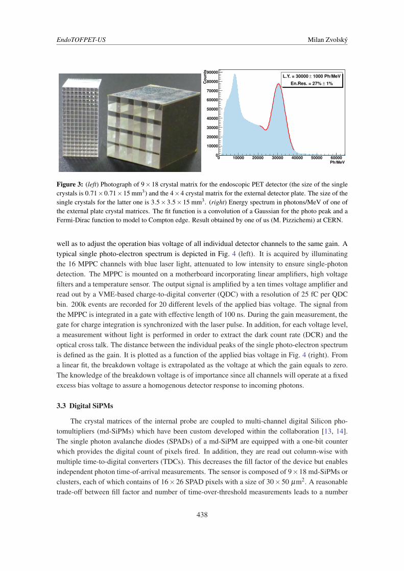
A photo of crystal samples for internal probe and external plate are shown in Fig. 3 (left).The LY of the crystal matrices is measured by coupling the matrices to a photomultiplier tube(PMT) since measuring the energy resolution with a SiPM is not optimal due to its non-linearresponse. For the external plate the average LY amounts to 33000 Ph/MeV (±5%) when wrappingthe crystal matrices with Vikuiti reflector foil and using optical grease to couple them to the PMT.This is more that four times higher than in the dry-contact and non-wrapped configuration. Thespread in LY among the different crystals of a matrix is ≈ 10%. The average energy resolutionof the whole matrix measures approximately (20± 7)%, sufficient to separate photo events fromCompton-scattered events, c.f. Fig. 3 (right). The optical cross talk within a crystal matrix is lessthat 5 % which is lower than the electronic cross talk and noise and which can easily be suppressedby setting a low energy threshold.
The average LY of the 9×18 matrix for the internal probe coupled with dry contact to a PMTand Vikuiti-covered back is approximately 12000 Ph/MeV [10] which can be increased by a factorof 2.3 by using optical grease between PMT and crystal. The average energy resolution for thismatrix amounts ≈ 18%. An automated LY measurement setup has been built to characterise the256 crystal matrices fast and reproducibly [11].
The timing properties of the crystal matrices coupled to analog SiPMs are measured withthe time-over-threshold method using an ultra-fast amplifier-discriminator chip NINO. The coin-cidence time resolution (CTR) between one matrix of the outer plate and one single crystal of theinternal probe can deliver a CTR down to 220 ps [12].
3.2 Analog SiPMs
The SiPMs chosen for the external plate are arrays of 4×4 discrete MPPCs from HamamatsuPhotonics (S12643-050CN). They have an active chip size of 3.0×3.0 mm2 and an inter-chip gapof 0.6 mm and are fitted with a Samtec ST4 connector. In contrast to monolithic arrays, which sharea common cathode, the discrete MPPCs feature individual cathodes, thus allowing differential read-out which reduces electronic cross talk as well as improves the time resolution [12]. The MPPCsused in this project exploit the through-silicon vertical-interconnect access technology, leading toless deadspace and a reduced connection length as compared to conventional wire-bonded SiPMs.They have been the result of recent developments by Hamamatsu Photonics. A mass characteri-sation of the MPPC arrays is currently performed in order to assure the quality of the devices as
437
EndoTOFPET-US Milan Zvolský
Ph/MeV
0 10000 20000 30000 40000 50000 60000
Counts
0
10000
20000
30000
40000
50000
60000
70000
80000
90000
1000 Ph/MeV±L.Y. = 30000
1%±En.Res. = 27%
Figure 3: (left) Photograph of 9×18 crystal matrix for the endoscopic PET detector (the size of the singlecrystals is 0.71×0.71×15 mm3) and the 4×4 crystal matrix for the external detector plate. The size of thesingle crystals for the latter one is 3.5×3.5×15 mm3. (right) Energy spectrum in photons/MeV of one ofthe external plate crystal matrices. The fit function is a convolution of a Gaussian for the photo peak and aFermi-Dirac function to model to Compton edge. Result obtained by one of us (M. Pizzichemi) at CERN.
well as to adjust the operation bias voltage of all individual detector channels to the same gain. Atypical single photo-electron spectrum is depicted in Fig. 4 (left). It is acquired by illuminatingthe 16 MPPC channels with blue laser light, attenuated to low intensity to ensure single-photondetection. The MPPC is mounted on a motherboard incorporating linear amplifiers, high voltagefilters and a temperature sensor. The output signal is amplified by a ten times voltage amplifier andread out by a VME-based charge-to-digital converter (QDC) with a resolution of 25 fC per QDCbin. 200k events are recorded for 20 different levels of the applied bias voltage. The signal fromthe MPPC is integrated in a gate with effective length of 100 ns. During the gain measurement, thegate for charge integration is synchronized with the laser pulse. In addition, for each voltage level,a measurement without light is performed in order to extract the dark count rate (DCR) and theoptical cross talk. The distance between the individual peaks of the single photo-electron spectrumis defined as the gain. It is plotted as a function of the applied bias voltage in Fig. 4 (right). Froma linear fit, the breakdown voltage is extrapolated as the voltage at which the gain equals to zero.The knowledge of the breakdown voltage is of importance since all channels will operate at a fixedexcess bias voltage to assure a homogenous detector response to incoming photons.
3.3 Digital SiPMs
The crystal matrices of the internal probe are coupled to multi-channel digital Silicon pho-tomultipliers (md-SiPMs) which have been custom developed within the collaboration [13, 14].The single photon avalanche diodes (SPADs) of a md-SiPM are equipped with a one-bit counterwhich provides the digital count of pixels fired. In addition, they are read out column-wise withmultiple time-to-digital converters (TDCs). This decreases the fill factor of the device but enablesindependent photon time-of-arrival measurements. The sensor is composed of 9×18 md-SiPMs orclusters, each of which contains of 16×26 SPAD pixels with a size of 30×50 µm2. A reasonabletrade-off between fill factor and number of time-over-threshold measurements leads to a number
438

EndoTOFPET-US Milan Zvolský
700 800 900 1000 1100 1200 1300 1400 1500
1
10
210
310
410Cou
nts
QDC bin
65.5 66.0 66.5 67.0 67.5 68.0 68.5 69.0Voltage [V]
0.0
0.5
1.0
1.5
2.0
Gain
[Me]
Vbd: (65.47 +/- 0.02 )VG: (0.469 +/- 0.006) Me
Figure 4: (left) Single photo-electron spectrum (blue) with a multiple Gaussian fit (red asterisks). The redhistogram is a spectrum from a dark run from which DCR and cross talk can be extracted. (right) Gain inmillion electrons as a function of the applied bias voltage as extracted from the aingle photo-electron spectra.The blue line is a straight line fit on the data points whose errors are negligible on this scale. The breakdownvoltage (V bd) and gain (G) at 1 V overvoltage, obtained from the fit, are given in the inlet. Results obtainedby one of us (A. Silenzi) at DESY.
of 48 TDCs per column of clusters and a fill factor of 57%. Combining the information of thedifferent timestamps statistically ensures that the lower bound of the theoretically achievable CTRis always reached and thus improves the CTR significantly [15, 16].
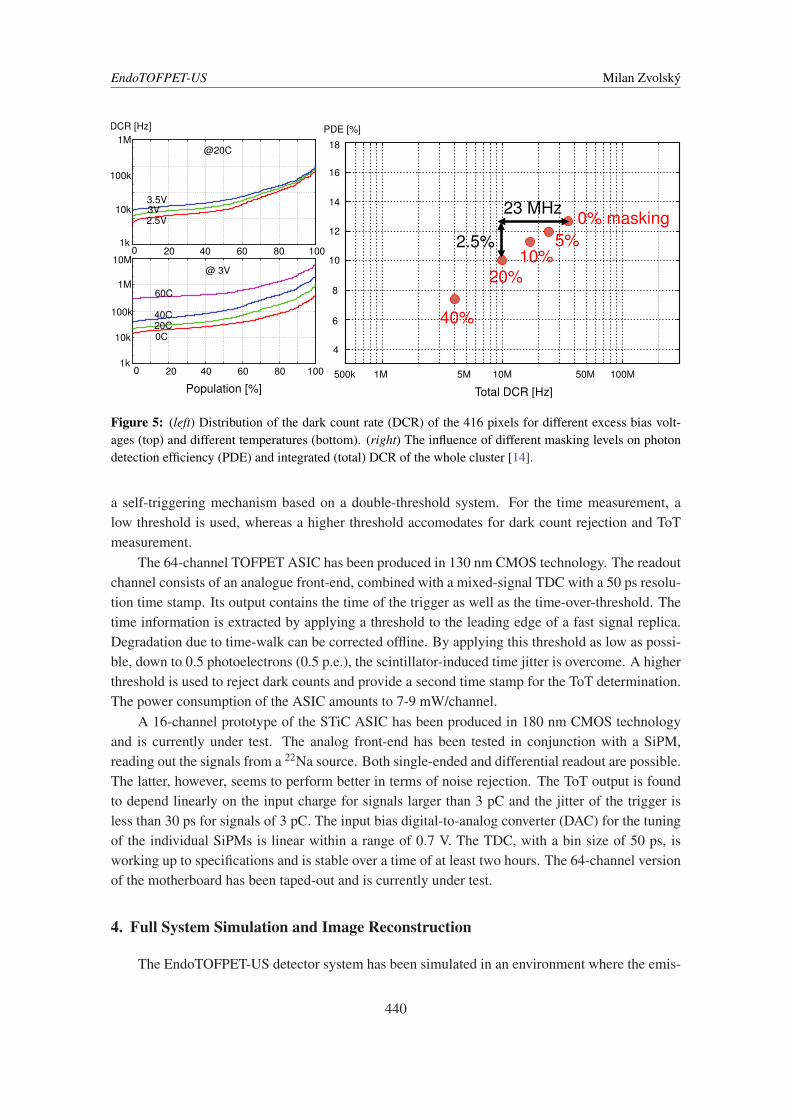
The 9× 18 md-SiPM chip has been fabricated and tested. It features in-situ statistical anal-ysis of the gamma events, real-time noise rejection, a high-speed interface with the DAQ as wellas multi-channel timestamping. Digital SiPMs typically suffer from high dark count rate (DCR)which, however, can be significantly reduced by cooling and by masking noisy pixels. Measure-ments with a test prototype suggest that the DCR at room temperature of around 40 MHz at 3 Vexcess bias can e.g. be reduced to 23 MHz with 10% masking. The DCR as a function of thepopulation of active pixels is depicted in Fig. 5 (left). Such small masking levels are able to reducethe DCR significantly while having only a small impact on the photon detection efficiency (PDE),c.f. Fig. 5 (right). The time jitter for one pixel of the prototype is determined to be 104 ps FWHM.The clusters incorporate a PDE of smaller than 17% and a cross talk of smaller than 10%.
3.4 ASIC
The analog SiPMs of the external plate are read out by dedicated 64-channel ASICs. The highdemands on the timing as well as the high channel density require the front-end electronics to befast, low-noise and to cope with the expected high dark count rate of the SiPMs. Moreover, be-cause of the high channel density of 4096 channels on 23×23 cm2, the front-end electronics needto integrate a high number of readout channels with a limited power budget in order to minimisecooling. Since the operation voltage of the SiPMs may vary by up to 0.5 V, the ASIC needs tobe able to tune the SiPM bias voltage for each individual channel by up to this amount. To fulfillthese requirements, two ASIC prototypes have been developed, StiC [17] and TOFPET ASIC [18].In both cases, the ASICs provide a fine time measurement and a time-over-threshold (ToT) mea-surement for each input pulse, where the latter one determines the pulse energy. The ASIC inhibits
439
EndoTOFPET-US Milan Zvolský
500k 1M 100M
Total DCR [Hz]
6
4
10
12
14
16
18
PDE [%]
50M10M
8
5M
0
Population [%]
20
1M
1k40 60 80 100
10k
100k
3V3.5V
2.5V
0 20
1M
1k40 60 80 100
10k
100k
10M
0C20C40C
60C
DCR [Hz]
23 MHz
2.5%0% masking
5%10%
20%
40%
@20C
@ 3V
Figure 5: (left) Distribution of the dark count rate (DCR) of the 416 pixels for different excess bias volt-ages (top) and different temperatures (bottom). (right) The influence of different masking levels on photondetection efficiency (PDE) and integrated (total) DCR of the whole cluster [14].
a self-triggering mechanism based on a double-threshold system. For the time measurement, alow threshold is used, whereas a higher threshold accomodates for dark count rejection and ToTmeasurement.
The 64-channel TOFPET ASIC has been produced in 130 nm CMOS technology. The readoutchannel consists of an analogue front-end, combined with a mixed-signal TDC with a 50 ps resolu-tion time stamp. Its output contains the time of the trigger as well as the time-over-threshold. Thetime information is extracted by applying a threshold to the leading edge of a fast signal replica.Degradation due to time-walk can be corrected offline. By applying this threshold as low as possi-ble, down to 0.5 photoelectrons (0.5 p.e.), the scintillator-induced time jitter is overcome. A higherthreshold is used to reject dark counts and provide a second time stamp for the ToT determination.The power consumption of the ASIC amounts to 7-9 mW/channel.
A 16-channel prototype of the STiC ASIC has been produced in 180 nm CMOS technologyand is currently under test. The analog front-end has been tested in conjunction with a SiPM,reading out the signals from a 22Na source. Both single-ended and differential readout are possible.The latter, however, seems to perform better in terms of noise rejection. The ToT output is foundto depend linearly on the input charge for signals larger than 3 pC and the jitter of the trigger isless than 30 ps for signals of 3 pC. The input bias digital-to-analog converter (DAC) for the tuningof the individual SiPMs is linear within a range of 0.7 V. The TDC, with a bin size of 50 ps, isworking up to specifications and is stable over a time of at least two hours. The 64-channel versionof the motherboard has been taped-out and is currently under test.
4. Full System Simulation and Image Reconstruction
The EndoTOFPET-US detector system has been simulated in an environment where the emis-
440

EndoTOFPET-US Milan Zvolský
sion of the photons and their passage through matter can be modelled. This includes the absorptionand scattering of the photons in the body as well as in the single detector components. The sim-ulation framework is based on the toolkit GATE v6 [19], a Geant4-based advanced open sourcesoftware for simulations in nuclear medical imaging. GATE is designed for symmetrical detectorsystems and has been customised to accommodate for the asymmetric design of EndoTOFPET-USdetector system. The simulation framework also allows for the rotation of the detectors duringthe data acquisition. An offline custom-made digitiser smears the exact position, time and energyinformation of the single events from simulation and creates physically-realistic coincidence pairsthat are stored in list-mode format and can be read by the image reconstruction software.
The first figure of merit of the PET detector is its sensitivity. It is defined as the number oftrue coincidences divided by the number of decays. It can be seen from a full-system simulation inFig. 6 (left) that the sensitivity increases with longer crystals. On the other hand, the coincidencetime resolution (CTR) deteriorates with longer crystals (decreases by about 45 % when increasingthe crystal length from 5 mm to 25 mm) [20]. As a tradeoff between optimising the sensitivity andoptimising the CTR, a crystal length of 15 mm has been chosen for both the external plate as wellas the probe crystals.
For the EndoTOFPET-US detector setup with the probe front face being located 12.5 mm fromthe source, the sensitivity amounts to about 7 cps/kBq. Due to a different solid-angle coverage, thedistance between source and probe influences the sensitivity. For a very small distance betweensource and probe of 2.5 mm, the sensitivity can be doubled, c.f. Fig. 6 (right).
5 10 15 20 25 30Crystal Length [mm]
2
3
4
5
6
7
8
9
10
11
Sens
itiv
ity
[cps
/kB
q]
Discrete MPPC v1, 3.1x3.1 mm2 cystalsDiscrete MPPC v2, 3.5x3.5 mm2 cystals
−16.5 −14.5 −12.5 −10.5 −8.5 −6.5 −4.5 −2.5 −0.5Distance Probe-Source [mm]
4
6
8
10
12
14
Sens
itiv
ity
[cps
/kB
q]
Figure 6: (left) Simulated full-system sensitivity as a function of the crystal length for two different SiPMmodels. (right) Simulated full-system sensitivity as a function of the distance between a point source andthe probe front (for outer-plate crystals of 3.5×3.5×15 mm as will be used in the final detector).
A dedicated image reconstruction software is being developed for the EndoTOFPET-US sys-tem in order to fulfil the demanding requirements. The image reconstruction is challenging due tothe following reasons: First, it needs to incorporate the TOF information. Since the endoscopicdetector is freehand, the volume of interest is undefined and changes continuously. PET typicallysuffers from low sensitivity and high noise, which is especially true for the EndoTOFPET-US sys-tem because of the limited field of view so that the reconstruction software needs to accomodate forthe limited solid angle. Furthermore, the image needs to be reconstructed on-line to provide guid-ance for the physician, so it needs to be fast. In order to overcome these difficulties, the histogram-mode iterative maximum-likelihood expectation-maximisation (ML-EM) reconstruction method isutilised [21]. In order to solve the massively parallel problem of inverting huge matrices the com-
441

EndoTOFPET-US Milan Zvolský
putation is performed on graphic processing units (GPUs). They enable a speedup by a factorof O(10) with respect to conventional central processing unit (CPU) computation, providing anon-line reconstructed image within the order of minutes.
The image resolution can be as low as 0.6 mm, if the size of the voxels that the region ofinterest is divided into is sufficiently small. Fig. 7 (centre) shows that pointsources with a radiusof 1 mm can still be reconstructed with a resolution of below 1 mm if surrounded by a backgroundactivity volume with a source-to-background activity-concentration ratio of 8 : 1. The reconstructedimage in Fig. 7 (right) shows the degradation of the image quality in the case of a limited rotationof only a few degrees. The resolution in y (coronal) is compatible to the full-rotation scenario whilethe image is blurred heavily in x.
Figure 7: (left) GATE simulation of the detector system and a source distribution. (center) Reconstructedimage with full rotation in 45◦ steps. (right) Reconstructed image with limited rotation.
5. Conclusion
In the scope of the EndoTOFPET-US project, a novel multimodal device for Ultrasound En-doscopy and Positron Emission Tomography is being developed. All the single components havebeen finalised. Comprehensive tests on the properties of the single components have been per-formed and confirm that the individual devices are fully functional and meet the specifications.Preliminary measurements suggest that a CTR of the order of 200 ps is within reach. Under idealconditions, image resolutions of 0.6 mm can be achieved. The project now enters the phase ofintegrating the single components into a working prototype. The commissioning and the clinicaltests are forseen for 2014.
Acknowledgments
The author thanks the EndoTOFPET-US collaboration for the privilege of representing it atthis conference.
This research project has received funding from the European Union 7th Framework Program(FP7/ 2007-2013) under Grant Agreement No. 256984 (EndoTOFPETUS) and is supported by aMarie Curie Early Initial Training Network Program (PITN-GA-2011-289355-PicoSEC-MCNet).
442

EndoTOFPET-US Milan Zvolský
References
[1] EndoTOFPET-US Proposal. Novel multimodal endoscopic probes for simultaneous PET/ultrasoundimaging for image-guided interventions. European Union 7th Framework Program (FP7/2007-2013)under Grand Agreement No. 256984, Health-2010.1.2-1.
[2] E. Garutti. EndoTOFPET-US - A novel multimodal tool for endoscopy and Positron EmissionTomography. In Nuclear Science Symposium and Medical Imaging Conference (NSS/MIC), 2012IEEE, pages 2096–2101, 2012.
[3] B. Frisch. Combining endoscopic ultrasound with Time-Of-Flight PET: The EndoTOFPET-USProject. Nucl. Instr. Meth. A, In press, 2013.
[4] Robert Koch-Institut (Hrsg) und die Gesellschaft der epidemiologischen Krebsregister inDeutschland e.V. (Hrsg). Krebs in Deutschland 2007/2008, 8. Ausgabe. Robert Koch-Institut, 2012.
[5] R. Bugalho, C. Gaston, M.D. Rolo, J.C. Silva, R. Silva, and J. Varela. EndoTOFPET-US dataacquisition system. Journal of Instrumentation, 8(02):C02049, 2013.
[6] CAMPCom: A Lightweight and Portable Communication Framework for Multimodal Image-GuidedTherapy . http://campar.in.tum.de/Main/CAMPCom. Accessed: 2013-08-16.
[7] A. Schoch, B. Fuerst, F. Achilles, S. Demirci, and N. Navab. A lightweight and portablecommunication framework for multimodal image-guided therapy. The Sixth International Workshopon Systems and Architectures for Computer Assisted Interventions (SACAI), September 2013.
[8] Medical electrical equipment - part 1: General requirements for basic safety and essentialperformance. Norm IEC 60601-1, 2005.
[9] T. Reichl, J. Gardiazabal, and N. Navab. Electromagnetic servoing - a new tracking paradigm. IEEETrans. Med. Imaging, 32(8):1526–1535, 2013.
[10] E. Auffray, F. Ben Mimoun Bel Hadj, N. Brillouet, P. Coudray, K. Doroud, G. Fornaro, B. Frisch,S. Gundacker, A. Knapitsch, P. Jarron, T. Meyer, M. Paganoni, K. Pauwels, M. Pizzichemi,M. Vangeleyn, and P. Lecoq. Design and performance of detector modules for the endoscopic PETprobe for the FP7-project EndoTOFPET-US. In Nuclear Science Symposium and Medical ImagingConference (NSS/MIC), 2012 IEEE, pages 3236–3240, 2012.
[11] J. Trummer, D. Aimard, E. Auffray, G. Chevenier, C. Laffay, P. Lecoq, P. Sempere-Roldan, andO. Teller. Scintillation properties of LuYAP and LYSO crystals measured with MiniACCOS, anautomatic crystal quality control system. In Nuclear Science Symposium Conference Record, 2005IEEE, volume 5, pages 2807–2810, 2005.
[12] K. Doroud, K. Auffray, P. Jarron, T. Meyer, and P. Lecoq. Differential readout: The technique tooptimise timing in a monolithic MPPC array. Nucl. Inst. Meth. A, 717, 5-10, 2013.
[13] S. Mandai, V. Jain, and E. Charbon. A fully-integrated 780×800µm2 multi-digital siliconphotomultiplier with column-parallel time-to-digital converter. In Proceedings of the ESSCIRC, pages89–92, 2012.
[14] S. Mandai and E. Charbon. Multi-channel digital SiPMs: Concept, analysis and implementation. InNuclear Science Symposium and Medical Imaging Conference (NSS/MIC), 2012 IEEE, pages1840–1844, 2012.
[15] M. Fishburn and E. Charbon. System Tradeoffs in Gamma-Ray Detection Utilizing SPAD Arrays andScintillators. IEEE Trans. Nucl. Sci. Vol. 57, No. 5, 2010.
443

EndoTOFPET-US Milan Zvolský
[16] S. Seifert, H.T. van Dam, and D.R. Schaart. The lower bound on the timing resolution of scintillationdetectors. Phys Med Biol. 57 1797-1814, 2012.
[17] W. Shen, K. Briggl, W. Chen, P. Fischer, A. Gil, T. Harion, M. Ritzert, and H.-C. Schultz-Coulon.STiC - A mixed mode chip for SiPM ToF applications. In Nuclear Science Symposium and MedicalImaging Conference (NSS/MIC), 2012 IEEE, pages 877–881, 2012.
[18] M.D. Rolo, R. Bugalho, F. Goncalves, G. Mazza, A. Rivetti, J.C. Silva, R. Silva, and J. Varela.TOFPET ASIC for PET applications. Journal of Instrumentation, 8(02):C02050, 2013.
[19] S. Jan et al. GATE: A simulation toolkit for PET and SPECT. Phys. Med. Biol. 49 4543, 2004.
[20] E. Garutti, K. Gadow, M. Goettlich, A. Silenzi, and Chen Xu. Single channel optimization for anendoscopic time-of-flight positron emission tomography detector. In Nuclear Science Symposium andMedical Imaging Conference (NSS/MIC), 2011 IEEE, pages 54–58, 2011.
[21] R.M. Lewitt and S. Matej. Overview of methods for image reconstruction from projections inemission computed tomography. Proceedings of the IEEE, 91(10):1588–1611, 2003.
444