Embed Size (px)
Citation preview
7/28/2019 Encyclopedia of Dust Collector
http://slidepdf.com/reader/full/encyclopedia-of-dust-collector 1/28
The Encyclopedia Of Filters – Dust Collection
Systems
Posted by dominickdalsanto on Feb 1, 2011 in Baghouse.com News, Dust Collection Blog, Dust Collector Maintenance, Operation & Optimization | 1 comment
5Share
By Dominick DalSanto Environmental Expert & Author
This article has been designed to educate customers by giving a brief overview of all the Dust Collection Syste
available today. A detailed explanation of the benefits and drawbacks of each type of system can be found in
further articles on Baghouse.com
What is a Dust Collector?
After the contaminated air is captured by a Dry Dust Collection system, either by means of a Central CollectioSystem, or in a unit Collector. The dust filled air then needs to be treated and the contaminates removed, befor
the air can be recirculated back into the facility or dispersed into the atmosphere. The Dust Collector separates
particles from the airstream and sends it on to its final destination.
Why are Dust Collectors Needed?
There are many reasons why having a proper Dust Collection System installed in your facility is needed, a few
important reasons are:
• To protect employees and society from exposure to pollution,
• To recover valuable products from the dust filled air • To facilitate compliance with health and air emission standards.
Types of Dust Collectors
The five principal types of industrial dust collectors that will be discussed in this article are:
• Cyclone Collectors (Inertial separators)
• Baghouses (Fabric collectors)• Wet scrubbers
• Electrostatic precipitators
• Unit collectors
Cyclone Collectors (Inertial Separators)
Inertial separators work by making use of one or more of the following forces centrifugal, gravitational, andinertial in order to separate dust from the airstream. Once separated, the dust is removed to a hopper by gravity
for temporary storage. While this type of collect can be used in applications where particle sizes are large and
7/28/2019 Encyclopedia of Dust Collector
http://slidepdf.com/reader/full/encyclopedia-of-dust-collector 2/28
only a “rough” air filtration is desired, the main usage for this type of collector is as a precleaner, to remove la particles and debris and avoid overloading and damaging more efficient dust collectors.
The three types of Inertial Separators are:
• Settling Chambers
• Baffle Chambers• Centrifugal Collectors
A Settling Camber is a large box installed into the ductwork. The sudden larger area for the airstream to pass
through causes the air stream to slow down, which in turns causes the larger particles to settle to the bottom of
chamber. This type of collector is rarely used as the primary dust collector due to it’s large space requirementsand low efficiency. However, the fact that it can be fashioned from almost any material and its simple design,
which requires little maintenance, leads it to being a wise choice as a precleaner for a more efficient Dust
Collector.
A Baffle Chamber has a fixed baffle plate that causes the airflow to rapidly change its direction, first turningdownward, and then making a 180 degree turn back up. In the process, the larger particles fall to the bottom of
chamber and can be collected from there. As with Settling Chambers this type of collector is best used as a
precleaner for another more efficient collector further in the collection system. Also like a Settling Chamber itrelatively simple design and low maintenance needs make it an excellent choice for the beginning of any large
scale collection system.
Centrifugal Collectors create a vortex in the airstream within an enclosure, similar to water going down a drai
Normally this is done by having the airstream enter the collect at an angle, which causes it to spin. As theairstream is spun around the collector, the particles strike the wall and fall into the hopper below.
Within this category there are two main types of systems in use:
• Single Cyclone systems
• Multiple Cyclone systems
A Single Cyclone Collector creates a dual vortex, a main downward vortex to disperse the coarser matter, and secondary upward vortex to remove the finer particles on the return to the outlet to the duct system.
A Multiple Cyclone Collector works in the same manner as the Single Cyclone variety albeit with several sma
dynamiter cyclones instead of just one. The multiple cyclones work in parallel and share the same air input and
output.
Between the two, the Multiple Cyclone Collector will operate more efficiently because of being longer in leng
and smaller in dynamiter. The smaller dynamiter cause the centrifugal force generated to be greater, and the
longer length allows for more contact with the surface of the collector by the particles thereby causing more
particles to be removed from the airstream. However, a greater loss of pressure is found in Multiple CycloneCollectors than in Single Cyclone Collectors.
Again as with the other kinds of Inertial Separators, this systems main advantage is the lack of moving parts th
requiring less maintenance and repair. While it can be designed to remove a specific size range of particles, it remains best used as a precleaner to eliminate coarse particles and ease the load on more efficient Dust Collect
further along in the system.
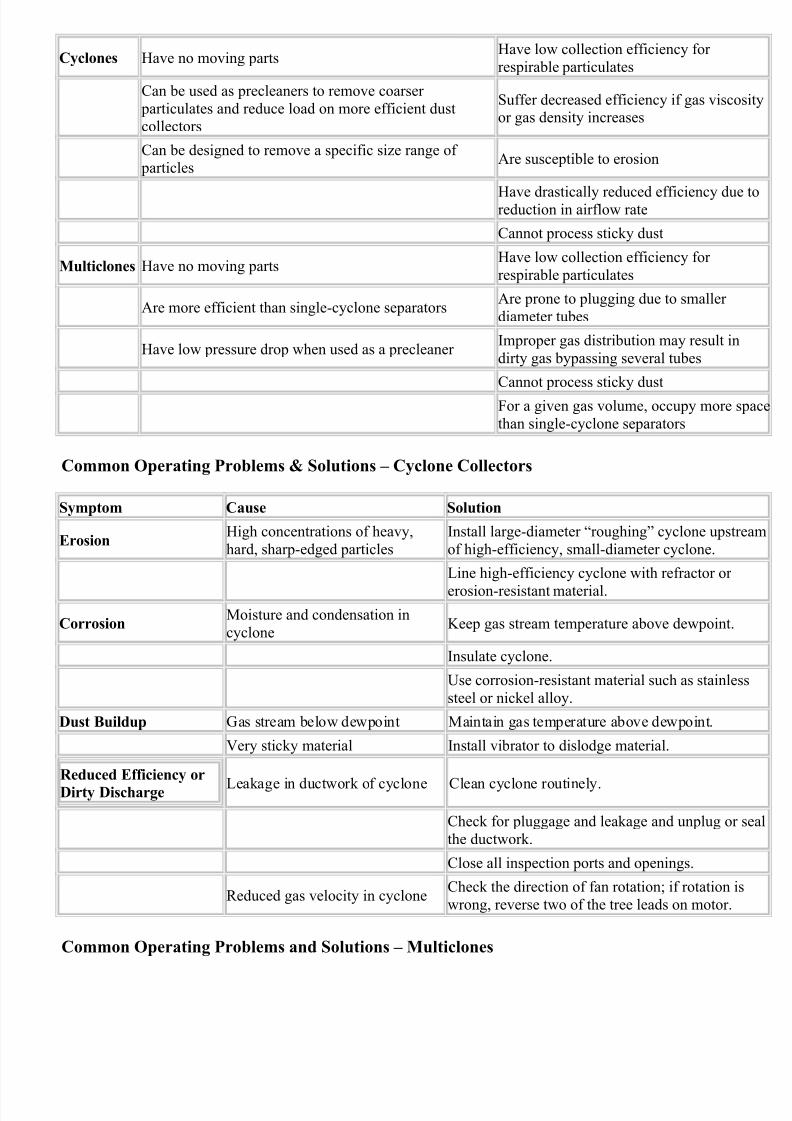
Advantages & Disadvantages – Centrifugal Collectors
Types Advantages Disadvantages
7/28/2019 Encyclopedia of Dust Collector
http://slidepdf.com/reader/full/encyclopedia-of-dust-collector 3/28
Cyclones Have no moving partsHave low collection efficiency for
respirable particulates
Can be used as precleaners to remove coarser
particulates and reduce load on more efficient dustcollectors
Suffer decreased efficiency if gas viscoor gas density increases
Can be designed to remove a specific size range of particles
Are susceptible to erosion
Have drastically reduced efficiency duereduction in airflow rate
Cannot process sticky dust
Multiclones Have no moving partsHave low collection efficiency for
respirable particulates
Are more efficient than single-cyclone separatorsAre prone to plugging due to smaller
diameter tubes
Have low pressure drop when used as a precleaner Improper gas distribution may result in
dirty gas bypassing several tubes
Cannot process sticky dust
For a given gas volume, occupy more s
than single-cyclone separators
Common Operating Problems & Solutions – Cyclone Collectors
Symptom Cause Solution
ErosionHigh concentrations of heavy,
hard, sharp-edged particles
Install large-diameter “roughing” cyclone upstr
of high-efficiency, small-diameter cyclone.
Line high-efficiency cyclone with refractor or
erosion-resistant material.
CorrosionMoisture and condensation in
cycloneKeep gas stream temperature above dewpoint.
Insulate cyclone.
Use corrosion-resistant material such as stainles
steel or nickel alloy.
Dust Buildup Gas stream below dewpoint Maintain gas temperature above dewpoint.
Very sticky material Install vibrator to dislodge material.
Reduced Efficiency or
Dirty Discharge Leakage in ductwork of cyclone Clean cyclone routinely.
Check for pluggage and leakage and unplug or s
the ductwork.
Close all inspection ports and openings.
Reduced gas velocity in cycloneCheck the direction of fan rotation; if rotation is
wrong, reverse two of the tree leads on motor.
Common Operating Problems and Solutions – Multiclones
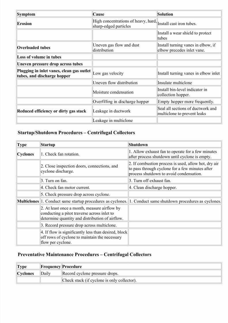
7/28/2019 Encyclopedia of Dust Collector
http://slidepdf.com/reader/full/encyclopedia-of-dust-collector 4/28
Symptom Cause Solution
ErosionHigh concentrations of heavy, hard,
sharp-edged particlesInstall cast iron tubes.
Install a wear shield to protect
tubes
Overloaded tubesUneven gas flow and dust
distribution
Install turning vanes in elbow, i
elbow precedes inlet vane.
Loss of volume in tubes
Uneven pressure drop across tubes
Plugging in inlet vanes, clean gas outlet
tubes, and discharge hopperLow gas velocity Install turning vanes in elbow in
Uneven flow distribution Insulate multiclone
Moisture condensationInstall bin-level indicator in
collection hopper.
Overfilling in discharge hopper Empty hopper more frequently.
Reduced efficiency or dirty gas stack Leakage in ductwork
Seal all sections of ductwork an
multiclone to prevent leaks
Leakage in multiclone
Startup/Shutdown Procedures – Centrifugal Collectors
Type Startup Shutdown
Cyclones 1. Check fan rotation.1. Allow exhaust fan to operate for a few minuteafter process shutdown until cyclone is empty.
2. Close inspection doors, connections, and
cyclone discharge.
2. If combustion process is used, allow hot, dry
to pass through cyclone for a few minutes after process shutdown to avoid condensation.
3. Turn on fan. 3. Turn off exhaust fan.
4. Check fan motor current. 4. Clean discharge hopper.
5. Check pressure drop across cyclone.
Multiclones 1. Conduct same startup procedures as cyclones. 1. Conduct same shutdown procedures as cyclo
2. At least once a month, measure airflow by
conducting a pitot traverse across inlet todetermine quantity and distribution of airflow.
3. Record pressure drop across multiclone.4. If flow is significantly less than desired, block off rows of cyclone to maintain the necessary
flow per cyclone.
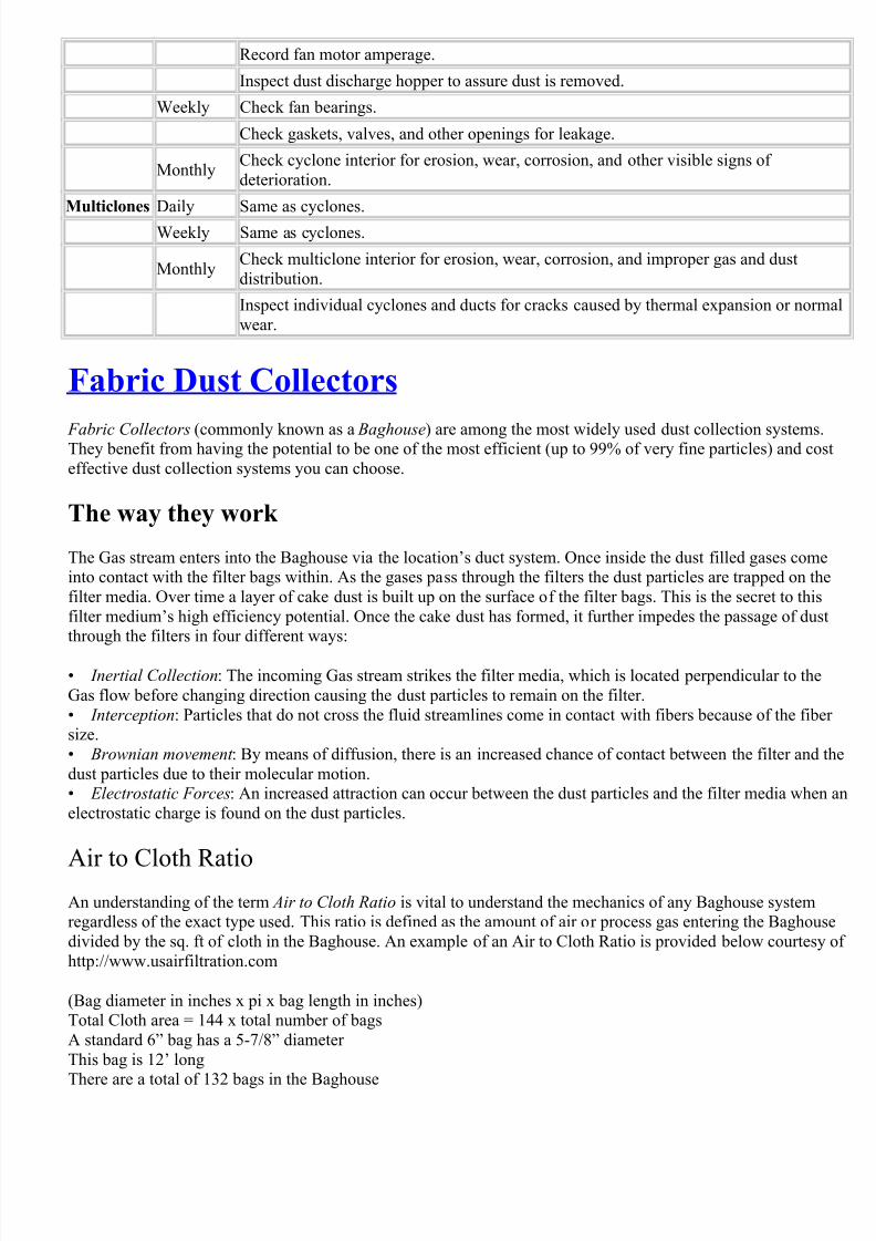
Preventative Maintenance Procedures – Centrifugal Collectors
Type Frequency Procedure
Cyclones Daily Record cyclone pressure drops.
Check stack (if cyclone is only collector).
7/28/2019 Encyclopedia of Dust Collector
http://slidepdf.com/reader/full/encyclopedia-of-dust-collector 5/28
Record fan motor amperage.
Inspect dust discharge hopper to assure dust is removed.
Weekly Check fan bearings.
Check gaskets, valves, and other openings for leakage.
MonthlyCheck cyclone interior for erosion, wear, corrosion, and other visible signs of
deterioration.
Multiclones Daily Same as cyclones.
Weekly Same as cyclones.
MonthlyCheck multiclone interior for erosion, wear, corrosion, and improper gas and dust
distribution.
Inspect individual cyclones and ducts for cracks caused by thermal expansion or norm
wear.
Fabric Dust Collectors
Fabric Collectors (commonly known as a Baghouse) are among the most widely used dust collection systemsThey benefit from having the potential to be one of the most efficient (up to 99% of very fine particles) and co
effective dust collection systems you can choose.
The way they work
The Gas stream enters into the Baghouse via the location’s duct system. Once inside the dust filled gases comeinto contact with the filter bags within. As the gases pass through the filters the dust particles are trapped on th
filter media. Over time a layer of cake dust is built up on the surface of the filter bags. This is the secret to this
filter medium’s high efficiency potential. Once the cake dust has formed, it further impedes the passage of dusthrough the filters in four different ways:
• Inertial Collection: The incoming Gas stream strikes the filter media, which is located perpendicular to the
Gas flow before changing direction causing the dust particles to remain on the filter.
• Interception: Particles that do not cross the fluid streamlines come in contact with fibers because of the fibesize.
• Brownian movement : By means of diffusion, there is an increased chance of contact between the filter and
dust particles due to their molecular motion.• Electrostatic Forces: An increased attraction can occur between the dust particles and the filter media when
electrostatic charge is found on the dust particles.
Air to Cloth RatioAn understanding of the term Air to Cloth Ratio is vital to understand the mechanics of any Baghouse systemregardless of the exact type used. This ratio is defined as the amount of air or process gas entering the Baghou
divided by the sq. ft of cloth in the Baghouse. An example of an Air to Cloth Ratio is provided below courtesy
http://www.usairfiltration.com
(Bag diameter in inches x pi x bag length in inches)Total Cloth area = 144 x total number of bags
A standard 6” bag has a 5-7/8” diameter
This bag is 12’ long
There are a total of 132 bags in the Baghouse
7/28/2019 Encyclopedia of Dust Collector
http://slidepdf.com/reader/full/encyclopedia-of-dust-collector 6/28
= (5-7/8” x 3.1416 x 144”) ÷ 144 x 132= (5.875” x 3.1416 x 144”) ÷ 144 x 132
= (2657.79) ÷ 144 x 132
= 18.46 SF of cloth per bag x 132 bagsTotal cloth area = 2,436 sq. ft.
Assume the Baghouse is handling 13,000 ACFM of air
Air to cloth ratio = ACFM ÷ total cloth area= 13,000 ÷ 2,436
= 5.34 : 1
Different Baghouse designs
There are three main types of Baghouse systems currently in use today. The same basic mechanics are presentall of them, the main difference being how filter bags are cleaned.
• Mechanical Shaker
• Reverse Air
• Reverse Jet (Or Pulse Jet)
A Mechanical Shaker is a design where the filter bags are suspended from the top of the Baghouse by horizon beams and fastened to a cell plate on the bottom. When the Gas stream enters at the bottom of the Baghouse it
then forced up through the inside of the tubular filter bags, thereafter passing unto the airflow outlet at the top.
The cleaning of this type of Baghouse is done by a shaking of the top horizontal bar that the filter bags areattached to. This is caused by a motor driven shaft and cam system that sends waves down the surface of the
filter bags causing the dust to fall off the interior of them into the hopper below. This Baghouse has a relative
low Air to Cloth Ratio requiring large amounts of space. Despite this draw back, the simple design remains anoted advantage, leading to this system being widely used in the mineral processing industry.
In a Reverse Air Baghouse, Filter bags are connected to a cell plate on the bottom of the Baghouse and are
suspended from an adjustable hanger frame on top. The Gas stream, as in the Mechanical Shaker design enters
into the Baghouse and passes through the filter bags from the bottom leading to the dust collecting again on thinterior of the filter bags, thereafter leaving through the outlet port at the top. Again the main difference in thi
style of Baghouse system when compared to others is the cleaning mechanism. In this system, a cleaning cycle
starts with injecting clean air into the Collector in the reverse direction of the normal flow. This causes thecompartment to become pressurized. The pressure causes the bags to collapse slightly releasing the cake dust t
crack and fall off to be collected by the hopper below. Since it is necessary to shut down normal airflow to th
Baghouse during the cleaning cycle, this type of Baghouse is normally compartmentalized so as to allow for o
a partial shutdown of the system.
With a Reverse Jet or Pulse Jet Baghouse, the same basic design is found as in the other types of Baghouse
design, however, with a few very important differences. In a Pulse Jet Baghouse, the filter bags are individuall
overlaid on a metal cage, which is then attached to a cell plate at the top of the compartment. The Gas streamenters the Baghouse at the bottom and is forced through the outside to the inside of the filter bags after which t
Gas stream exits the compartment from the outlet port at the top. The main advantage of this Baghouse is that
does not require a shutdown of any kind to run a cleaning cycle. A digital sequential timer is attached to the on
of the filter bags inside the Baghouse. This timer signals a solenoid valve to start the cleaning cycle when itdetects a certain amount of build up on the bag. It consists of a small burst of compressed air being fired down
through the filter bags. Which cause the excess cake dust to fall off into hopper at the bottom of the Baghouse
where it can be collected. The cleaning cycle of the Pulse Jet collectors provides a more complete cleaning andreconditioning of the filter bags than in the Shaker, and Reverse Air designs. Also the short nature of the clean
cycle also leads to a reduction in the recirculation and redeposit of dust. Finally, enabled by the continuous
cleaning feature of the design, this kind of collection system has a higher Air to Cloth Ratio so the space
requirements are much lower than in other systems.
7/28/2019 Encyclopedia of Dust Collector
http://slidepdf.com/reader/full/encyclopedia-of-dust-collector 7/28
Cartridge Collectors
Unlike Baghouse collectors which feature the use of woven or felt filter bags, Cartridge Collectors use perfora
metal cartridges that are cylindrical shaped and open on one or both ends lined with a pleated nonwoven filteri
media. Once installed, one end of the cartridge is sealed off and the open end is used for the clean exhaust.Similar to a Baghouse, the Gas stream is forced through the outside of the cartridge to the inside where it then
exits back into the system. Cartridge Collectors are also compatible with Reverse or Pulse Jet cleaning. Large
numbers of these Collectors can be installed and used for continuous filtration for a location’s dust collection
system.
Advantages and Disadvantages – Baghouses
Types Advantages Disadvantages
Shaker
Baghouses
Have high collection
efficiency for respirable
dust
Have low air-to-cloth ratio
(1.5 to 2 ft/min)
Can use strong woven bags, which can withstand
intensified cleaning cycleto reduce residual dust
buildup
Cannot be used in high
temperatures
Simple to operateRequire large amounts of
space
Have low pressure drop for equivalent collection
efficiencies
Need large numbers of filter
bags
Consist of many moving
parts and require frequent
maintenancePersonnel must enter Baghouse to replace bags,
creating potential for
exposure to toxic dust
Can result in reduced
cleaning efficiency if even a
slight positive pressureexists inside bags
Reverse Air
Baghouses
Have high collection
efficiency for respirabledust
Have low air-to-cloth ratio
(1 to 2ft/min)
Are preferred for high
temperatures due to gentlecleaning action
Require frequent cleaning
because of gentle cleaningaction
Have low pressure drop for equivalent collection
efficiencies
Have no effective way toremove residual dust
buildup
Cleaning air must be filtered
Require personnel to enter
7/28/2019 Encyclopedia of Dust Collector
http://slidepdf.com/reader/full/encyclopedia-of-dust-collector 8/28
baghouse to replace bags,
which creates potential for toxic dust exposure
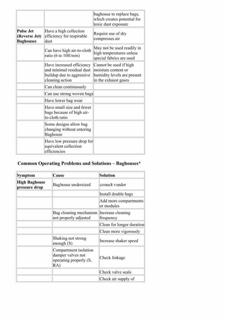
Pulse Jet
(Reverse Jet)
Baghouses
Have a high collectionefficiency for respirable
dust
Require use of dry
compresses air
Can have high air-to-cloth
ratio (6 to 10ft/min)
May not be used readily in
high temperatures unless
special fabrics are used
Have increased efficiencyand minimal residual dust
buildup due to aggressive
cleaning action
Cannot be used if highmoisture content or
humidity levels are present
in the exhaust gases
Can clean continuously
Can use strong woven bags
Have lower bag wear
Have small size and fewer
bags because of high air-to-cloth ratio
Some designs allow bag
changing without entering
Baghouse
Have low pressure drop for equivalent collection
efficiencies
Common Operating Problems and Solutions – Baghouses*
Symptom Cause Solution
High Baghouse
pressure dropBaghouse undersized consult vendor
Install double bags
Add more compartmentsor modules
Bag cleaning mechanismnot properly adjusted
Increase cleaningfrequency
Clean for longer duration
Clean more vigorously
Shaking not strongenough (S)
Increase shaker speed
Compartment isolationdamper valves not
operating properly (S,
RA)
Check linkage
Check valve seals
Check air supply of
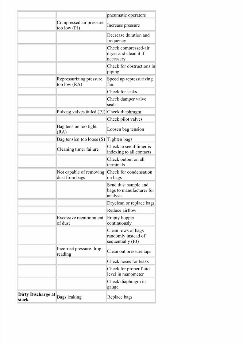
7/28/2019 Encyclopedia of Dust Collector
http://slidepdf.com/reader/full/encyclopedia-of-dust-collector 9/28
pneumatic operators
Compressed air pressure
too low (PJ)Increase pressure
Decrease duration and
frequency
Check compressed-air
dryer and clean it if
necessaryCheck for obstructions in piping
Repressurizing pressure
too low (RA)
Speed up repressurizing
fan.
Check for leaks
Check damper valve
seals
Pulsing valves failed (PJ) Check diaphragm
Check pilot valvesBag tension too tight
(RA)Loosen bag tension
Bag tension too loose (S) Tighten bags
Cleaning timer failureCheck to see if timer is
indexing to all contacts
Check output on allterminals
Not capable of removingdust from bags
Check for condensationon bags
Send dust sample and bags to manufacturer for
analysis
Dryclean or replace bags
Reduce airflow
Excessive reentrainmentof dust
Empty hopper continuously
Clean rows of bags
randomly instead of
sequentially (PJ)
Incorrect pressure-drop
readingClean out pressure taps
Check hoses for leaks
Check for proper fluid
level in manometer
Check diaphragm in
gauge
Dirty Discharge at
stack
Bags leaking Replace bags
7/28/2019 Encyclopedia of Dust Collector
http://slidepdf.com/reader/full/encyclopedia-of-dust-collector 10/28
Isolate leaking
compartment or module
Tie off leaking bags and
replace them later
Bag clamps not sealingSmooth out cloth under
clamp and re-clamp
Check and tighten
clampsFailure of seals in jointsat clean/dirty air
connection
Caulk or weld seams
Insufficient filter cake
Allow more dust buildup
on bags by cleaning lessfrequently.
Use precoating on bags
(S, RA).
Bags too porous
Send bag in for
permeability test andreview with
manufacturer
High compressed-
air consumption
(PJ)
Cleaning cycle too
frequent
Reduce cleaning cycle, if
possible
Pulse too long Reduce pulsing duration
Pressure too highReduce supply pressure,if possible
Diaphragm valve failureCheck diaphragm andsprings
Check pilot valve
Reduced
compressed-air
pressure (PJ)
Compressed-air
consumption too highSee previous solutions
Restrictions in
compressed-air piping
Check compressed-air
piping
Compressed-air dryer
plugged
Replace dessicant in the
dryer
Bypass dryer temporarily, if possible
Replace dryer
Compressed-air supply
line too smallConsult design
Compressor worn out Replace rings
Check for worn
components
Rebuild compressor or
consult manufacturer
7/28/2019 Encyclopedia of Dust Collector
http://slidepdf.com/reader/full/encyclopedia-of-dust-collector 11/28
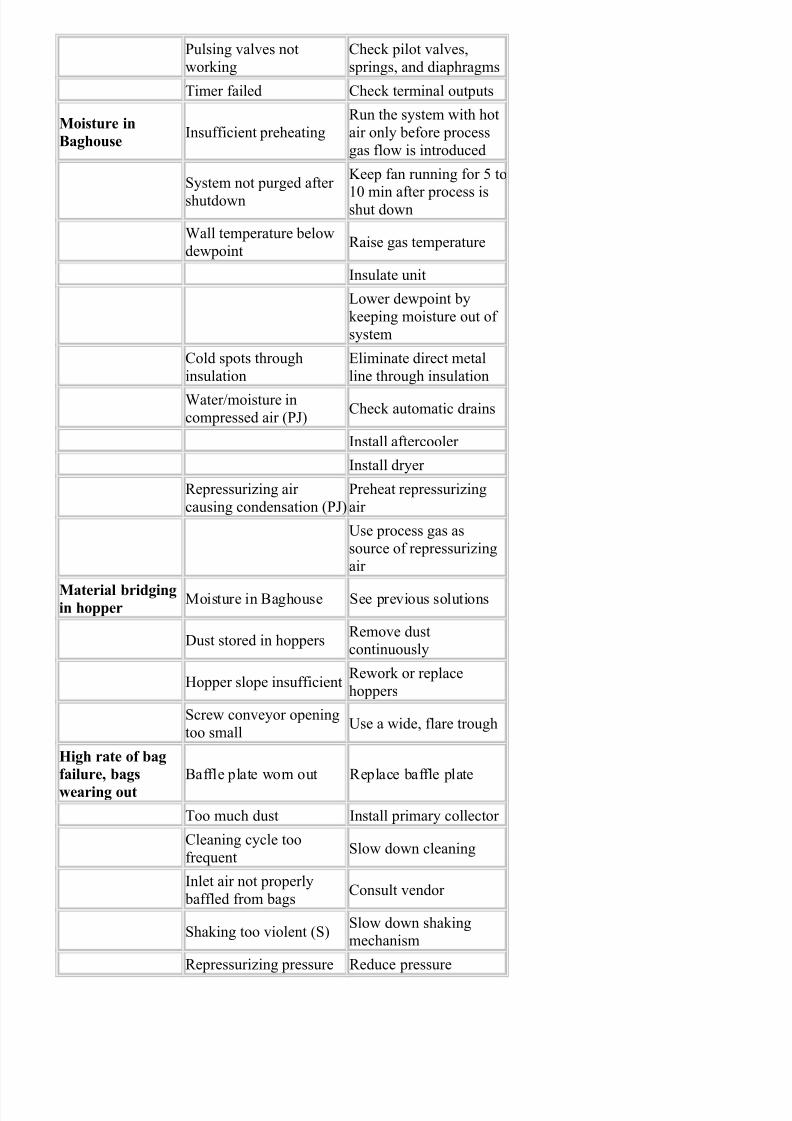
Pulsing valves not
working
Check pilot valves,
springs, and diaphragms
Timer failed Check terminal outputs
Moisture in
BaghouseInsufficient preheating
Run the system with hot
air only before process
gas flow is introduced
System not purged after
shutdown
Keep fan running for 5 to
10 min after process isshut down
Wall temperature below
dewpointRaise gas temperature
Insulate unit
Lower dewpoint by
keeping moisture out of
system
Cold spots through
insulation
Eliminate direct metal
line through insulation
Water/moisture in
compressed air (PJ)Check automatic drains
Install aftercooler
Install dryer
Repressurizing air
causing condensation (PJ)
Preheat repressurizing
air
Use process gas as
source of repressurizingair
Material bridgingin hopper
Moisture in Baghouse See previous solutions
Dust stored in hoppersRemove dustcontinuously
Hopper slope insufficientRework or replace
hoppers
Screw conveyor opening
too smallUse a wide, flare trough
High rate of bag
failure, bags
wearing out
Baffle plate worn out Replace baffle plate
Too much dust Install primary collector
Cleaning cycle too
frequentSlow down cleaning
Inlet air not properly
baffled from bagsConsult vendor
Shaking too violent (S)Slow down shakingmechanism
Repressurizing pressure Reduce pressure
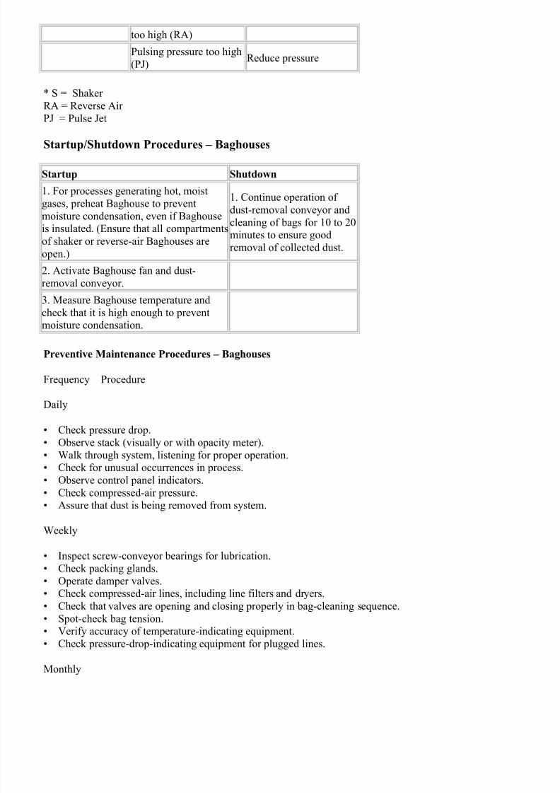
7/28/2019 Encyclopedia of Dust Collector
http://slidepdf.com/reader/full/encyclopedia-of-dust-collector 12/28
too high (RA)
Pulsing pressure too high
(PJ)Reduce pressure
* S = Shaker
RA = Reverse Air
PJ = Pulse Jet
Startup/Shutdown Procedures – Baghouses
Startup Shutdown
1. For processes generating hot, moist
gases, preheat Baghouse to prevent
moisture condensation, even if Baghouseis insulated. (Ensure that all compartments
of shaker or reverse-air Baghouses are
open.)
1. Continue operation of
dust-removal conveyor and
cleaning of bags for 10 to 20minutes to ensure good
removal of collected dust.
2. Activate Baghouse fan and dust-
removal conveyor.
3. Measure Baghouse temperature and
check that it is high enough to preventmoisture condensation.
Preventive Maintenance Procedures – Baghouses
Frequency Procedure
Daily
• Check pressure drop.
• Observe stack (visually or with opacity meter).
• Walk through system, listening for proper operation.• Check for unusual occurrences in process.
• Observe control panel indicators.
• Check compressed-air pressure.• Assure that dust is being removed from system.
Weekly
• Inspect screw-conveyor bearings for lubrication.• Check packing glands.
• Operate damper valves.• Check compressed-air lines, including line filters and dryers.
• Check that valves are opening and closing properly in bag-cleaning sequence.
• Spot-check bag tension.• Verify accuracy of temperature-indicating equipment.
• Check pressure-drop-indicating equipment for plugged lines.
Monthly
7/28/2019 Encyclopedia of Dust Collector
http://slidepdf.com/reader/full/encyclopedia-of-dust-collector 13/28
• Check all moving parts in shaker mechanism.• Inspect fans for corrosion and material buildup.
• Check drive belts for wear and tension.
• Inspect and lubricate appropriate items.• Spot check for bag leaks.
• Check hoses and clamps.
• Check accuracy of indicating equipment.• Inspect housing for corrosion.
Quarterly
• Inspect baffle plate for wear.
• Inspect bags thoroughly.
• Check duct for dust buildup.• Observe damper valves for proper seating.
• Check gaskets on doors.
• Inspect paint, insulation, etc.• Check screw conveyor for wear or abrasion.
Annually
• Check fan belts.
• Check welds.• Inspect hopper for wear
Wet Scrubbers
Another effective method of dust collection is the use of Wet Scrubbers (Air Washers). These systems use a
scrubbing liquid (usually water) to filter out finer dust particles. After being filtered the Gas Stream is then sethrough a mist eliminator (demister pads) to remove the excess moisture from the Gas stream. Afterward the G
stream exits the collector through the outlet port and returns back into the system. Wet Scrubbers are ideal:
• For the collection of explosive material
• Where “slurry” produced could be reused (either in other parts of process or sold)• Where chemical reactions could be generated with other collection methods
• To absorb excess air
Wet scrubbers have the advantage of low start up costs and low space requirements. They are well suited for
treating high temperature and high humidity Gas streams. They also are able to process both air and “sticky” particulates. The main disadvantages are that they are costly to operate, require a precleaner for any heavy du
loads, cause water pollution that then needs to be addressed, and can erode with high air velocities.
There are a vast variety of different designs and applications of this type of filtration system but all of them hathree basic operations they perform:
• Gas-humidification: The gas-humidification process conditions fine particles to increase their size so they c
be collected more easily.
• Gas-liquid contact: This is the entire basis for the operation of this type of system. The method of contact between the liquid is done in four main ways:
• Inertial impaction takes place when the Gas stream is forced to flow around the droplets in its path. The
stream separates and flows around the droplet. However the larger particles continue to be carried by inertial
7/28/2019 Encyclopedia of Dust Collector
http://slidepdf.com/reader/full/encyclopedia-of-dust-collector 14/28
force in a straight path coming in direct contact with the liquid.• Interception: Finer particles while not directly coming in contact with the droplets, do however brush up
against the side of them causing them to be absorbed into the liquid.
• Diffusion occurs when a fine mist is created from the liquid being used. As the particles pass through the mthey make contact with the surfaces of the droplets by means of the Brownian effect, or diffusion.
• Condensation nucleation is the effect of a gas being cooled below its dew point while within a moisture ric
environment, causing the vapor to condense of the surface of the particles thereby encapsulating them.
• Liquid separation: After going through the cleaning phase the remaining liquid and contaminates must beremoved before the Gas stream can be sent back into the system. This is accomplished by means of a Mist
Eliminator (Demister Pads). Which remove the liquid and dust mixture from the Gas stream and send it to a
collector. Once in the collector, the solid waste settles to the bottom where it is removed by means of a drag chsystem to be deposited in a dumpster or another collection area.
Wet Scrubbers are further categorized by pressure drop (in inches water gauge) as follows:
• Low-energy scrubbers (0.5 to 2.5)
• Low- to medium-energy scrubbers (2.5 to 6)• Medium- to high-energy scrubbers (6 to 15)
• High-energy scrubbers (greater than 15)
The large amount of different Wet Scrubbers in use makes it impossible to comment on every single design inarticle. However a brief overview of the most common types will enable you to understand the basic operation
procedures present in all of them.
Low Energy Scrubbers:
• The most basic design is that of a Gravity Spray Tower Scrubber . In this system the contaminated air enter
the bottom of the cylindrically shaped scrubber and rises through a mist of water sprayed from nozzles at the t
The dirty water collects at the bottom of the tank and the clean air (mist) exits from the top of the collector. Thcollector has a relatively low efficiency compared to other kinds of Wet Scrubbers. However it’s main advanta
is it can handle very heavy dust loads without getting backed up.
• Dynamic wet precipitators also called Wet Fan Scrubbers are a popular design used for medium energyscrubbing applications. In this system the Gas stream passes through a larger fan that is constantly kept wet wi
the cleaning liquid. The particles are trapped in the liquid and are then by means of centrifugal force thrown of
the spinning fan blades unto the sides of the collector where they eventually settle at the bottom enabling them
be collected.
• Orifice Scrubbers work in a very similar way to inertial separators but with one important difference, Orifi
Scrubbers use a water surface to capture the dust particles. When the Gas stream enters the collector it is rapid
redirected when it comes in contact with the water surface. Causing the dust particles to be removed from the G
stream. A greater efficiency can be obtained by the addition of liquid spray nozzles to further separate thecontaminates from the Gas stream. While these are an effective filtration system one should note that they tend
be ineffective against fine particles as these tend to be redirected off of the water surface by the high surface
tension.
Low to Medium Energy Scrubbers:
• Wet Cyclone Scrubbers are nearly identical to their normal cyclone collector counterparts. In a Wet Cyclon
Scrubber the Gas stream enters the collector and is then forced into a cyclone movement by the strategic placement of stationary scrubbing vanes. Liquid is introduced at the top of the collector allowing the dust
particles to stick to the wet walls of the collector when they are thrown off by the vortex. As with dry Cyclone
Collectors, this type of system has the benefit of few to no moving parts and it is efficient for particles up to 5uand above.
7/28/2019 Encyclopedia of Dust Collector
http://slidepdf.com/reader/full/encyclopedia-of-dust-collector 15/28
Medium to High Energy Scrubbers:
• Packed Bed Scrubbers consist of a bed of packing media, which is then sprayed with water. The packingmedia allows for a very wide distribution of the water, which in turn allows the Gas stream to have the maxim
contact with the water during its passage though the collector. Air enters at the bottom of the collector where i
first makes contact with the water in the recirculation tank. Then it is forced up through the various layers of thfiltering media, and after being sent through a Mist Eliminator is sent back into the system via the exit port at t
top.
Within the category of Packed Bed Scrubbers there are three different variations on the implementation of this
filtering mechanism they are:
• Cross-flow scrubbers are designed to minimize height for low-profile applications. In this design the packemedia is laid as sheets perpendicular to the Gas stream. The Gas stream enters in one side of the Scrubber and
flows horizontally through it passing though the packing media and then exiting out the opposite side
• Co-current flow scrubbers• Counter-current flow scrubbers
High energy Scrubbers:
• Venturi Scrubbers make use of the Venturi effect to accelerate the Gas stream to speeds of 12,000 to 36,00ft/min. The Gas stream enters into the Scrubber through a Venturi shaped inlet where it is sprayed with water.
water hitting the extremely high speed air causes it to instantly atomize. The very fine water droplets attach to
dust particles and form a slurry, which then falls to the bottom of the collector. After passing through a Misteliminator the Gas stream is sent back into the system.
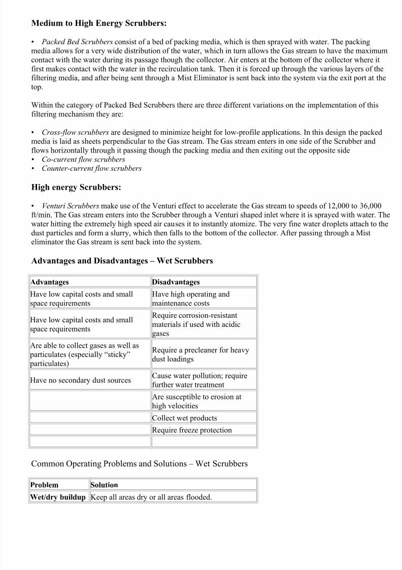
Advantages and Disadvantages – Wet Scrubbers
Advantages Disadvantages
Have low capital costs and small
space requirements
Have high operating and
maintenance costs
Have low capital costs and small
space requirements
Require corrosion-resistant
materials if used with acidicgases
Are able to collect gases as well as particulates (especially “sticky”
particulates)
Require a precleaner for heavydust loadings
Have no secondary dust sourcesCause water pollution; require
further water treatment
Are susceptible to erosion athigh velocities
Collect wet products
Require freeze protection
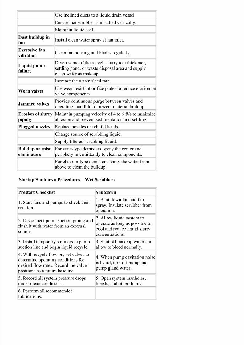
Common Operating Problems and Solutions – Wet Scrubbers
Problem Solution
Wet/dry buildup Keep all areas dry or all areas flooded.
7/28/2019 Encyclopedia of Dust Collector
http://slidepdf.com/reader/full/encyclopedia-of-dust-collector 16/28
Use inclined ducts to a liquid drain vessel.
Ensure that scrubber is installed vertically.
Maintain liquid seal.
Dust buildup in
fanInstall clean water spray at fan inlet.
Excessive fan
vibrationClean fan housing and blades regularly.
Liquid pump
failure
Divert some of the recycle slurry to a thickener,
settling pond, or waste disposal area and supply
clean water as makeup.
Increase the water bleed rate.
Worn valvesUse wear-resistant orifice plates to reduce erosion on
valve components.
Jammed valvesProvide continuous purge between valves and
operating manifold to prevent material buildup.
Erosion of slurry
piping
Maintain pumping velocity of 4 to 6 ft/s to minimize
abrasion and prevent sedimentation and settling.Plugged nozzles Replace nozzles or rebuild heads.
Change source of scrubbing liquid.
Supply filtered scrubbing liquid.
Buildup on mist
eliminators
For vane-type demisters, spray the center and
periphery intermittently to clean components.
For chevron-type demisters, spray the water from
above to clean the buildup.
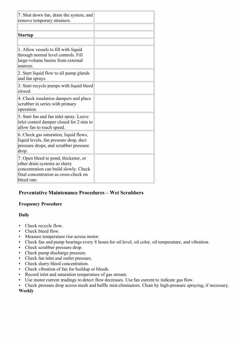
Startup/Shutdown Procedures – Wet Scrubbers
Prestart Checklist Shutdown
1. Start fans and pumps to check their rotation.
1. Shut down fan and fan
spray. Insulate scrubber fromoperation.
2. Disconnect pump suction piping and
flush it with water from an external
source.
2. Allow liquid system tooperate as long as possible to
cool and reduce liquid slurry
concentrations.
3. Install temporary strainers in pumpsuction line and begin liquid recycle.
3. Shut off makeup water andallow to bleed normally.
4. With recycle flow on, set valves todetermine operating conditions for
desired flow rates. Record the valve
positions as a future baseline.
4. When pump cavitation noiseis heard, turn off pump and
pump gland water.
5. Record all system pressure drops
under clean conditions.
5. Open system manholes,
bleeds, and other drains.
6. Perform all recommended
lubrications.
7/28/2019 Encyclopedia of Dust Collector
http://slidepdf.com/reader/full/encyclopedia-of-dust-collector 17/28
7/28/2019 Encyclopedia of Dust Collector
http://slidepdf.com/reader/full/encyclopedia-of-dust-collector 18/28
• Check wet/dry line areas for material buildup. Clean, if necessary.• Check liquid spray quantity and manifold pressure on mist eliminator automatic washdown.
• Inspect fans on dirty applications for corrosion, abrasion, and particulate buildup.
• Check bearings, drive mechanisms, temperature rise, sprocket alignment, sprocket wear, chain tension, oillevel, and clarifier rakes.
• Check ductwork for leakage and excessive flexing, Line or replace as necessary.
• Clean and dry pneumatic lines associated with monitoring instrumentation.
Semiannually
• Verify accuracy of instruments and calibrate.
• Inspect orifice plates.
• Clean electrical equipment, including contacts, transformer insulation, and cooling fans.• Check and repair wear zones in scrubbers, valves, piping, and ductwork.
• Lubricate damper drive mechanisms and bearings. Verify proper operation of dampers and inspect for leak
Electrostatic Precipitators
Electrostatic Precipitators use electrostatic forces to collect dust from the Gas stream. Several high power DirCurrent Discharge Electrodes are places inside the collector. The incoming Gases pass by the first set of
Discharging Electrodes (ionizing section) that give the particles a negative charge (ionization). The now ionize
particles travel pass the next set of electrodes (the collection section) that carry a positive charge. The positivecharged plates attract the negatively charged particles causing them to collect on the plates. Cleaning is
accomplished by vibrating the electrodes either continuously, or at a timed interval, causing the captured dust
fall off into a hopper below. All of this can be done while the system is operating normally.
Electrostatic Precipitators are best used in an ambient capture type system with low particle loads. Without anautomated self-cleaning feature, this type of collector can very easily reach its maximum particle retention lim
which will result in a system failure. Further, for a high dust load system a great amount of dust storage is need
Media Filtration (Baghouse) or Pleated Filtering Media (Cartridge Collectors) provide a much great surface arfor dust storage than Electrostatic Precipitator systems do. However the advantages of this system are great fo
their intended applications. They have the ability to be extremely efficient (in excess of 99.9% in some cases),
function within vary large temperature ranges (between 700 °F and -1300°F), and can have large flow rates wiminimal pressure and temperature changes. They are also very well suited for the collection of fine dust partic
as well as materials like acids and tars which other system may have difficulty with.
All electrostatic Precipitators have four main components:
• A Power supply to provide the system with electricity
• An Ionizing section to negatively charge the incoming particles• A cleaning system designed to remove collected particles from the Electrode collection plates
• A housing to enclose the Precipitator section
Within the category of Electrostatic Precipitator Collectors, there are two main types of systems:
• High Voltage Single State Precipitators (Cottrell type)• Low Voltage Dual State Precipitators (Penny type)
High Voltage Single State Precipitators are further divided between two main designs:
Plate Precipitators are made up of several flat parallel plate collectors that are usually between 8 and 12in apa
Placed directly in the middle of each set of directly adjacent plates are a series of high voltage (40,000-70,000volts) DC Discharge Electrodes. As the Gas stream passes through the plates it is ionized by the Discharge
Electrodes and then immediately deposited unto the collection plates. The plates are then cleaned by vibrating
7/28/2019 Encyclopedia of Dust Collector
http://slidepdf.com/reader/full/encyclopedia-of-dust-collector 19/28
plates causing the debris to fall into a hopper or collection bin below. The majority of Single State Precipitatoruse today are of the plate variety.
Tubular Precipitators operate in the same manner as Plate Precipitators however in a different configuration. T
design uses a tubular shaped collection device with the Discharge Electrodes placed in the middle of the tube.
the Gas stream flows through the tube it is first ionized by the Discharge Electrode in the center, and then thecharged particles are attracted to the inside of the positively charged tube. The cleaning mechanism can be one
nearly identical to that of Plate Precipitators or it can be used as part of a Wet Static Precipitator system, wher
the sides of the Precipitator are flushed with water thereby cleaning them.Tubular Precipitators are widely used in the mineral processing industry. They are highly valuable for use in h
temperature Gas streams (boiler exhaust gas on power plants) because of their ability to adjust to the expansion
and contraction of metal parts in the system. In addition this type of collector is also able to handle vapor collection, containing adhesive, “sticky”, radioactive, and extremely toxic compounds.
Low Voltage Dual Stage Precipitators contain several grounded plates about one inch from each other with
another intermediate plate that also contains a charge. This system uses a much lower voltage than the High
Voltage type (a 13,000-15,000 volt DC supply with intermediate supply of 7,500 compared to 40,000 to 70,00This type of system is widely used to collect fumes and particles generated by welding, grinding or burning
operations. They are also used in hooded and ducted welding machines and welding booths.
Low Voltage Dual Stage Precipitators have the advantages of being highly efficient, the possibility of a self contained washing system, and a longer service life since cleaning is only required on a monthly basis. Howev
because maintenance requires removing the Precipitator Frames and the manual cleaning of the cleaning
assemblies which are quite delicate, this type of Precipitator requires a great amount more care and caution to
used when performing maintenance.
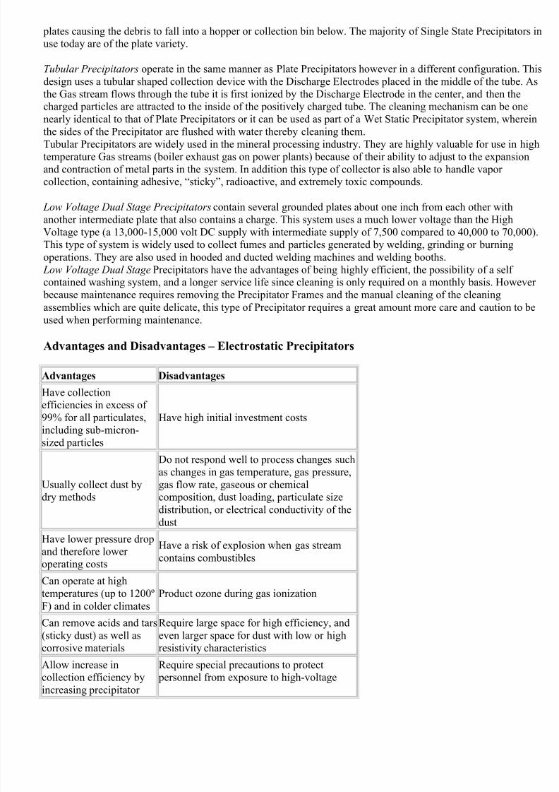
Advantages and Disadvantages – Electrostatic Precipitators
Advantages Disadvantages
Have collection
efficiencies in excess of
99% for all particulates,including sub-micron-
sized particles
Have high initial investment costs
Usually collect dust bydry methods
Do not respond well to process changes such
as changes in gas temperature, gas pressure,
gas flow rate, gaseous or chemicalcomposition, dust loading, particulate size
distribution, or electrical conductivity of the
dust
Have lower pressure drop
and therefore lower operating costs
Have a risk of explosion when gas stream
contains combustibles
Can operate at high
temperatures (up to 1200º
F) and in colder climates
Product ozone during gas ionization
Can remove acids and tars
(sticky dust) as well as
corrosive materials
Require large space for high efficiency, and
even larger space for dust with low or high
resistivity characteristics
Allow increase incollection efficiency by
increasing precipitator
Require special precautions to protect personnel from exposure to high-voltage
7/28/2019 Encyclopedia of Dust Collector
http://slidepdf.com/reader/full/encyclopedia-of-dust-collector 20/28
size
Require little power Require highly skilled maintenance
personnel
Unit Collectors
For certain applications, Unit Collectors are a better choice for a facilities needs than a conventional Central
Collection System. These collectors control contamination at their source. They benefit from low initial cost,direct return of captured material to the main material flow, and very low space requirements. These collectors
best used when the dust source is isolated, portable or changes position often. Some examples of instances wh
this type of collector might be useful are dust-producing operations, such as bins and silos or remote belt-
conveyor transfer points.
Depending on the particular desired application is there are a number of different designs available to choose
from with a capacity of 200 to 2,000 ft3/min. The two main types are:
• Fabric Collectors• Cyclone Collectors
Unit Fabric Collectors are very similar to their bigger relatives used in a Central Collection System. They usuemploy either a Mechanical Shaker, or a Pulse Jet system for cleaning. This type is well suited for the collectio
of fine particles such as in the mineral processing industry.
Unit Cyclone Collectors also operate on the same principles are the kind used in Central Collection Systems. Dis collected and deposited into a hopper, which then can be removed later for cleaning. This type of collector i
best used in the collection of coarse of larger particles.
Central Collection SystemEvery Dust Collection System must have a Central Collection System in place in order to send the contaminate
air to the filtration system. A Central Collection System consists of a series of collection inlets, and the necess
duct work to transport the dust laden Gas stream to the collector and afterward on to be either recirculated back
into the facility or dispersed into the atmosphere. The pressure in this duct system is supplied by the Fan andMotor System.
Fan and Motor
Choosing the right Fan and Motor System requires a number of different factors to be taken into consideration
including but not limited to:
• Volume required
• Fan static pressure
• Type of material to be handled through the fan (For example, a Radial Blade Fan should be used with fibromaterial or heavy dust loads, and a nonsparking construction must be used with explosive or flammable
materials.)
• Limitations in space
• Acceptable levels of noise caused by the fan• Required operational temperature (For example, sleeve bearings are suitable to 250º F; ball bearings to 550
F.)
• Adequate size to handle pressure and volume requirements with minimum horsepower usage

7/28/2019 Encyclopedia of Dust Collector
http://slidepdf.com/reader/full/encyclopedia-of-dust-collector 21/28
• Whether any corrosive materials are going to be handled and what protective coatings may be needed• Ability of fan to accommodate small changes in total pressure while maintaining the necessary air volume
• Need for an outlet damper to control airflow during cold starts (If necessary, the damper may be interlocke
with the fan for a gradual start until steady-state conditions are reached.)
Also to be considered is what type of drive system for the fan you plan to use. A Direct Drive fan is run directoff of a drive shaft from the motor, this provides for lower space needs, but places the fan at a constant
unchangeable speed. While Belt Driven fan, which uses a belt to flywheel configuration needs more space, it c
allow for the fan speed to be easily changed which is vital for some applications.
There are two main types of fan designs that are used in industrial applications:
• Centrifugal fans
• Axial-flow fans
A Centrifugal Fan (also called a Squirrel-cage fan for its resemblance rodent exercise devices) is a fan build w
blades (or ribs) surrounding a central hub. The air enters into the side of the fan and then turns 90° and isaccelerated and thrown out of the fan by means of centrifugal force. The diverging shape of the scroll also
converts a portion of the velocity pressure into static pressure. The fan is driven by means of a drive shaft that
extends out from the center hub of the fan.
There are three main types of Centrifugal fan blades that can be used:
• Forward Curved Blades
• Backward Curved Blades
• Straight Radial Blades
Forward Curved Bladed Fans have blades that are curved in the direction of the rotation of the fan. These fanshighly sensitive to particulate buildup and are used for high airflow, low pressure applications.
Backward Curved Bladed Fans contain blades that are positioned away from the fans rotation direction. These
fans will provide an efficient operation, and can be used in Gas streams with light to medium particle
concentration. While they can be fitted with wear protection, this type of blade can still become backed up if th particle load gets to be too heavy. This fan type is most often employed in medium speed, high pressure, and
medium airflow applications.
Straight Radial Bladed Fans provide the best choice for heavy particle loads. This design features a series of
blades that extend straight out from the center hub. This design is used for high pressure, high speed and lowvolume applications.
Fan dampeners
Fan dampeners are metal plates that can be adjusted to reduce the energy usage of the fan. Placed on the Outle
port of a fan, they are used to impose a flow resistance to control the Gas stream. They also can be placed on t
Inlet port, which can perform the same function, as well as redirect how the Gas stream enters into the fan.
Axial Flow Fans
Axial Flow Fans have blades that are mounted unto a center drive shaft. They induce the air to move parallel t
the shaft the blades are mounted on by the screw-like action of the propellers. The air is blown across the axis the fan hence the name Axial Flow Fans. This type of fan is commonly used in systems with low resistance
levels.
7/28/2019 Encyclopedia of Dust Collector
http://slidepdf.com/reader/full/encyclopedia-of-dust-collector 22/28
The three main different designs of Axial Flow Fans are:
• Propeller
• Tube Axial
• Vane Axial
Propeller Fans is the most simple fan design. It is used to move large an amount of air against very low static pressure from the rest of the system. General and Dilution ventilation are two common uses for this type of ax
fan.
The Tube Axial design is very similar to a normal propeller type fan, except that the propeller is enclosed in an
open ended cylinder. This design is more efficient than simple propeller types and is often used in moving Gasstreams filled with condensable fumes or pigments.
Vane Axial Fans are nearly identical to Tube Axial Fans. But these contain specially attached vanes that are
designed to straighten the Gas stream as is passes through the fan. These can produce high static pressures rela
to this type of fan. However these fans are in most applications used only for clean air.
Fan Rating Table
Once all of the preceding material has been examined, the final step in the selection of the proper fan for your system is to consult a Fan Rating Table. This is used to list all of the specifications for the various fans produc
by a certain manufacturer. When reviewing a Fan Rating Table one must keep these few points in mind:
• The rating tables show all of the possible pressures and speeds that can be achieved within the limits of the
fan’s normal operation range.• A fan that operates at a single or fixed speed and has a fixed blade setting will only have one possible ratin
The only way to gain multiple ratings is by varying the speed and the blade setting.
• It may be possible to obtain the same fan in different construction classes• Increasing the exhaust volume will in turn increase the static and total pressure in the system
Fan installation
Once a system has been installed in the field, inevitably certain differences between design and field installatiowill require a field test to be done to find the exact measurements of static pressure and volume. This step is
crucial in order for a proper fan system to be selected. A few brief points are good to keep in mind during the
installation process that can cause your real world values to change from the original design specifications:
• Elbows and bends near the fan’s discharge will increase the systems resistance thereby lowering your fan’s performance
• Make sure to install the impeller in the proper direction desired.
• Certain types of fittings such as elbows, mitered elbows and square ducts, can cause a nonuniform airflowwhich in turn will again lower performance
• Build up of debris in the inlets, blades, passages as well as obstructions should be checked and remedied
• In a belt driven system one must check the motor sheave and fan sheave are properly aligned and that prop belt tension is present
Electric Motors
An Electric Motor is what supplies the power necessary to operate the fan (Blower) in the Dust Collection
System. Electric Motors are usually grouped as either Induction, or Synchronous designs. Induction designs a
the only ones that are used in Dust Collection Systems today.
7/28/2019 Encyclopedia of Dust Collector
http://slidepdf.com/reader/full/encyclopedia-of-dust-collector 23/28
Induction Motors normally operate on three phase AC current. The two most common types used in DustCollection Systems are:
• Squirrel Cage Motors are generally used where a constant speed is desired
• Slip Ring Motors by contrast are general purpose or continuous rated motors that are used in applications
where there is a need for an adjustable speed in the motor.
Another important design consideration is whether the Motor is one of these two enclosure designs:
• Drip Proof and Splash Proof Motor are types of Open Enclosed Motors, which use a kind of electric motor
enclosure that has vents to allow airflow but to prevent liquids and solids from entering the motor. This design
not suitable for application where particles that can damage the interior of a motor are found in the ambientatmosphere around the motor.
• Totally Enclosed Motors have an exterior fan mounted unto the backside of the motor drive end. The fan
blows air over the motor enclosure to provide additional cooling for the motor. Since the actual motor is totallyenclosed this design provides the best protection against dust and other contaminates that might damage the mo
if allowed inside.
Both Types can also be constructed in explosion and dust ignition proof models to protect against accidental
ignition of dust particles.The following factors need to be considered when choosing which motor meets your needs:
• Horsepower and RPMs
• Power supply needs such as voltage, single or three phase AC and frequency• The environment in which the motor will have to operate (humidity, temperature, open flames or corrosive
elements
• What kind of load is going to be placed on the motor (fan and other drive mechanisms) and power compan
restrictions on cold starts.• Sufficient power supply for cold starts
• Overload protection needed for the particular motor
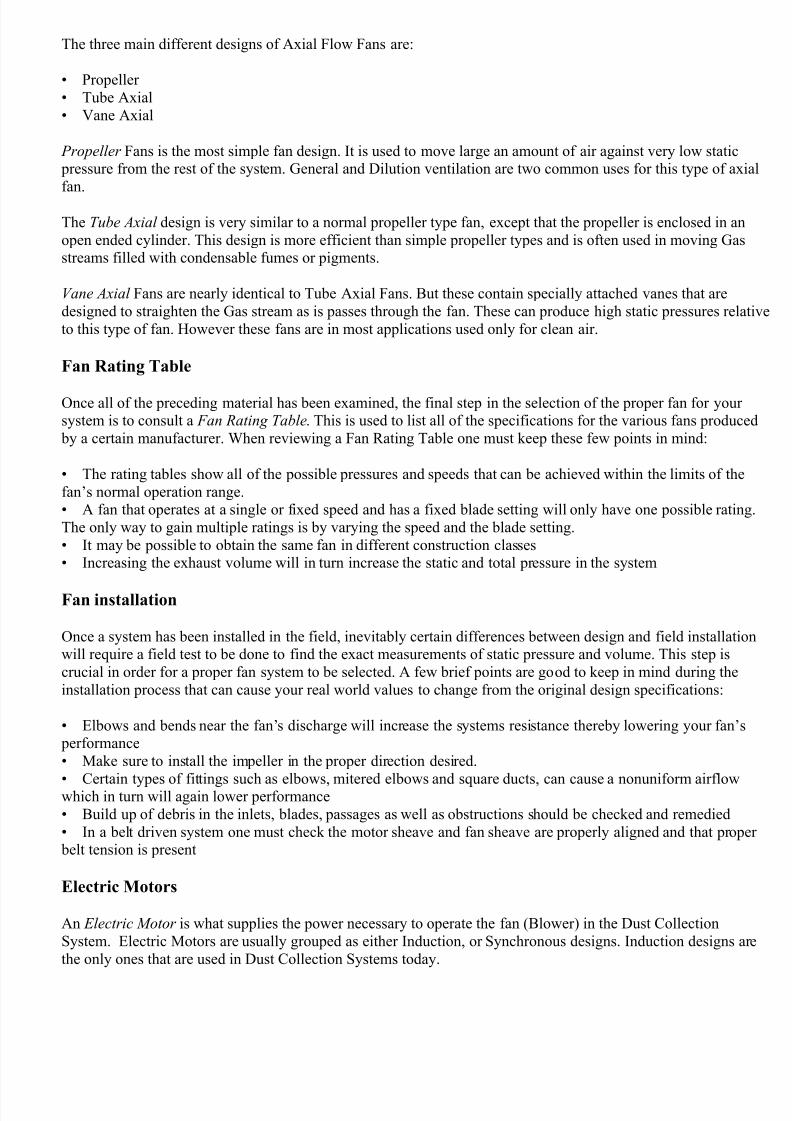
Fan & Motor Troubleshooting Chart
Symtom Probable Cause Solution
Insufficient
airflow, low
ft3/min
Fan
Forward curved impeller
installed backwardsReinstall impeller
Fan running backwards
Change fan rotation by
reversing two of the three
leads on the motor Impeller not centeredwith inlet collar(s)
Make impeller and inletcollar(s) concentric
Fan speed too lowIncrease fan speed byinstalling smaller diameter
pulley
Elbows or other
obstructions restricting
airflow
Redesign ductwork
Install turning vanes in elbow
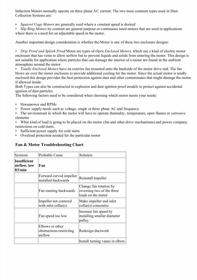
7/28/2019 Encyclopedia of Dust Collector
http://slidepdf.com/reader/full/encyclopedia-of-dust-collector 24/28
Remove obstruction in
ductwork
No straight duct at faninlet
Install straight length of
ductwork, at least 4 to 6 ductdiameters long, where
possible
Increase fan speed to
overcome this pressure loss
Obstruction near fan
outlet
Remove obstruction or
redesign ductwork near fanoutlet
Sharp elbows near fanoutlet
Install a long radius elbow, if possible
Install turning vanes in elbow
Improperly designed
turning vanesRedesign turning vanes
Projections, dampers, or
other obstructions near fan outlet
Remove all obstructions
Duct System
Actual system more
restrictive (more resistant
to flow) than expected
Decrease system’s resistance
by redesigning ductwork
Dampers closedOpen or adjust all dampers
according to the design
Leaks in supply ducts Repair all leaks in supply duct
Too muchairflow, high
ft3/min
Fan
Backward inclinedimpeller installed
backwards (high
horsepower)
Install impeller as
recommended by
manufacturer
Fan speed too fast Reduce fan speed
Install larger diameter pulley
on fan
Duct System
Oversized ductwork; less
resistance
Redesign ductwork or add
restrictions to increase
resistance
Access door openClose all access and
inspection doors
Low static
pressure, high
ft3/min
Fan
Backward inclined Install impeller as
7/28/2019 Encyclopedia of Dust Collector
http://slidepdf.com/reader/full/encyclopedia-of-dust-collector 25/28
impeller installed
backwards (highhorsepower)
recommended by
manufacturer
Fan speed too high Reduce fan speed
Install larger diameter pulley
on fan
Duct System
System has lessresistance to flow thanexpected
Reduce fan speed to obtaindesired flow rate
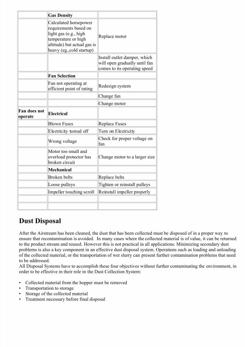
Gas Density
Gas Density lower than
anticipated (due to high
temperature gases or high
altitudes)
Calculate gas flow rate atdesired operating conditions
by applying appropriate
correction factors for high
temperature or altitudeconditions
Low staticpressure, low
ft3/min
Duct System
Fan inlet and/or outlet
conditions not same astested
Increase fan speed
Install smaller diameter pulley
on fan
Redesign ductwork
High static
pressure, low
ft3/min
Duct System
Obstructions in system Remove obstructions
Duct system too
restrictedRedesign ductwork
Install larger diameter ducts
High
horsepowerFan
Backward inclined
impeller installed backwards
Install impeller as
recommended bymanufacturer
Fan speed too high Reduce fan speed
Install larger diameter pulley
on fan
Duct System
Oversized ductwork Redesign ductwork
Access door openClose all access/inspection
doors
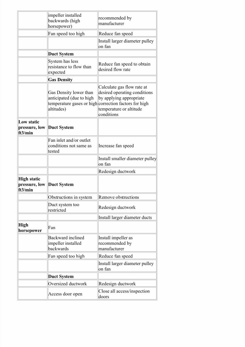
7/28/2019 Encyclopedia of Dust Collector
http://slidepdf.com/reader/full/encyclopedia-of-dust-collector 26/28
Gas Density
Calculated horsepower
requirements based on
light gas (e.g., hightemperature or high
altitude) but actual gas is
heavy (eg.,cold startup)
Replace motor
Install outlet damper, which
will open gradually until fancomes to its operating speed
Fan Selection
Fan not operating atefficient point of rating
Redesign system
Change fan
Change motor
Fan does not
operateElectrical
Blown Fuses Replace Fuses
Electricity turned off Turn on Electricity
Wrong voltageCheck for proper voltage on
fan
Motor too small and
overload protector has broken circuit
Change motor to a larger size
Mechanical
Broken belts Replace belts
Loose pulleys Tighten or reinstall pulleys
Impeller touching scroll Reinstall impeller properly
Dust Disposal
After the Airstream has been cleaned, the dust that has been collected must be disposed of in a proper way toensure that recontamination is avoided. In many cases where the collected material is of value, it can be return
to the product stream and reused. However this is not practical in all applications. Minimizing secondary dust problems is also a key component in an effective dust disposal system. Operations such as loading and unloadi
of the collected material, or the transportation of wet slurry can present further contamination problems that neto be addressed.
All Disposal Systems have to accomplish these four objectives without further contaminating the environment
order to be effective in their role in the Dust Collection System:
• Collected material from the hopper must be removed
• Transportation to storage
• Storage of the collected material
• Treatment necessary before final disposal
7/28/2019 Encyclopedia of Dust Collector
http://slidepdf.com/reader/full/encyclopedia-of-dust-collector 27/28
Removal Of Dust From The Hopper
The hopper must be emptied of the collected dust on a regular basis to prevent overfilling. Often this process i
done while the collector is still operating. If this is the case, rotary air locks, or tipping valves need to be used
order to maintain a positive air seal and thus avoid massive pressure loss that would be detrimental to the norm
operation of the system. Some materials display what is called a bridging tendency, which is a tendency to stictogether and form long strands that can over time build up into bridge like formations that can impede the norm
operations within a hopper. If material of this kind is present in the system, special equipment such as bin
vibrators, rappers, or air jets should be used to ensure that the material that has a bridging tendency does notinterfere with normal operation of the hopper.
Dust Transportation
Once the dust has been removed from the collector, it must be transported to a storage area where is can be giv
any final treatments needed before it is disposed of. There are four main systems that can be used to transport
collected material to holding there are:
• Screw conveyers• Air conveyers
• Air Slides
• Pressurized piping system for wet material (Slurry)
Screw conveyers use rotating shaft to move material to the desired location. These systems are very effectivemethods of dust transportation. However several areas of concern in this type of system are that they tend to h
a noted lack of easy access for maintenance purposes, the castings and bearings can wear out easily when used
with abrasive materials with air leaks being the end result.
Air Conveyers are used mainly for dry dust applications. Making use of a high velocity low air volume princip
these collectors are a great choice because of their few moving parts and their ability to move dust both vertica
and horizontally. The main concerns with this system are that the piping can over time suffer from excessive w
from abrasive compounds. They also require large initial investments of capital and have higher operating cost
Air Slides are widely used for light dust loads with nonabrasive materials. Air fluidization of the dust is the ma
operating principle behind this system. This system while able to transport great amounts of material has the
downside of only being able to do so in a horizontal direction. Areas of concern are the need to maintain a
constant down pitch in the ductwork, and greater maintenance costs.
Pressurized piping systems are needed when transporting the slurry made from using a Wet Scrubber design. T
system is used to send the slurry to a settling pond for further treatment. Great care must be taken by the opera
of this system to ensure that no leakage occurs which would result in an environmental hazard caused by wate pollution.
Dust Storage
Storage tanks and Silos are the most common storage locations for dry dust compounds after their collection.These sites are then fitted to allow loading of the material into enclosed trucks or rail cars below.
When using a wet collection system often times a settling pond is needed. In a settling pond the captured
particles are separated by means of the process of decantation. The slurry from the Wet Scrubbers is left to sit
a large pond or basin, allowing the captured particles to over time slowly settle to the bottom of the pond;afterwards the clean water is discharged. Again certain factors to consider in the use of a settling pond are that
water holding area can only be decanted in the warmer, dryer part of the year, and in most instances two settlin
ponds are needed to operate efficiently.
7/28/2019 Encyclopedia of Dust Collector
http://slidepdf.com/reader/full/encyclopedia-of-dust-collector 28/28
Final Disposal
When deciding on a final disposal method, one must remember that great care needs to exercised in order to av
recirculation of the dust by the wind. Sometimes in because of this concern, and for easier transportation, the
captured material is processed into pellets before final disposal. Generally four different options are available
the final disposal of the collected material:• Placement in a landfill
• Recycling
• Byproduct utilization• Collected material may be suitable for backfilling land fills and quarries
Selection of a Dust Collector
The differences in design, operation, efficiency, space requirement, construction, and maintenance needs, as was the initial start up, operating, and maintenance costs differ greatly between various products and systems.
However in choosing which system will meet your needs the best, the following point should be considered:
Dust concentration and Particle size – Within any kind application the specific sizes and dust concentrations c
vary enormously. Therefore, knowing the exact range of particle size and concentration levels that will be preswill be vital in your choosing the proper Collection System.
Degree of collection required – How intensive of a filtration action is needed is determined by several factors.
The exact dangers and hazards of the contaminates to be captured, its potential as a public health risk or nuisan
site location, the allowable emission rate by the regulatory body for the given substance, characteristics of thedust, and any recyclable value.
Characteristics of the Gas stream – Differences in Gas stream temperatures and humidity levels can great affe
certain types of collectors. For example Gas temperatures above 180° F (82°C) will destroy many types of filt
media (Filter Bags) used in Fabric Collectors (Baghouses). Water vapor or steam can blind certain types of FilMedia. Corrosive and other chemicals can erode certain metals and other materials used in the construction of
many Collectors.
Types of Dust – Certain types of Collectors have a great deal of physical contact between the particles and the
Collector itself. A number of different materials such as silica or metal ore are quite abrasive and can causeerosion through prolonged contact with the Collector. Other “sticky” compounds can attach themselves to the
interior surfaces of the collector and cause blockages. The size and distinct shape of some types of dust render
certain collection methods useless. When certain types of materials are fluidized into the air they become highcombustible. Under these circumstances Electrostatic Precipitators are instantly ruled out, along with most Ine
Separators.
Disposal Methods – Differences in disposal methods betweens different locations. Collectors can be arranged
unload their collected matter either in a continuous mode or at a predetermined time interval. Removal of collected matter from dry systems can also result in secondary causes of dust pollution and contamination. Wh
using a Wet Scrubber System will eliminate this concern, proper handling of slurry created during the cleaning
cycle will involve an entirely different set of problems, such as precautions against water pollution, and propercare and maintenance of the retention ponds.