Embed Size (px)
Citation preview

Your Global Automation PartnerYour Global Automation Partner
Ri…-QR24 Encoders with an IO-Link InterfaceOperating instructions

2 Hans Turck GmbH & Co. KG | T +49 208 4952-0 | F +49 208 4952-264 | [email protected] | www.turck.com
3 2015/11
1 About this manual 5
1.1 Target groups 51.2 Explanation of symbols 51.3 Other documents 51.4 Feedback about this manual 5
2 Notes on the product 6
2.1 Product identification 62.2 Scope of delivery 72.3 Legal requirements 72.4 Manufacturer and service 7
3 For your safety 7
3.1 Intended use 73.2 Obvious misuse 83.3 General safety notes 8
4 Product description 8
4.1 Device overview 84.1.1 Indication elements 94.2 Properties and features 94.3 Operating principle 94.4 Functions and operating modes 94.4.1 IO-Link mode 94.5 Encoders – Components and accessories 104.5.1 Encoders – QR24 sensor 104.5.2 Encoders – QR24 positioning element 104.5.3 Encoders – QR24 adapter sleeves 124.5.4 Encoders – Protecting rings and mounting sets for QR24/EQR24 device types 134.5.5 Encoders – General accessories 14
5 Mounting 15
5.1 Front mounting – Shaft diameters up to 20 mm 155.2 Rear mounting – Shaft diameters up to 20 mm 165.3 Mounting on large rotatable machine part 16
6 Connecting 17
6.1 Wiring diagram 17
7 Commissioning 17
7.1 Setting IO-Link mode 17
8 Operating 17
8.1 LED indication 18
9 Setting 18
9.1 Setting via IO-Link 189.1.1 IO-Link parameters 189.1.2 IO-Link process data 18
Enco
ders
with
IO-L
ink
Inte
rfac
e
Table of contents

4 Hans Turck GmbH & Co. KG | T +49 208 4952-0 | F +49 208 4952-264 | [email protected] | www.turck.com
10 Troubleshooting 19
11 Maintenance 19
12 Repair 19
12.1 Returning devices 19
13 Decommissioning 19
14 Disposal 19
15 Technical data 20

5 2015/11
Enco
ders
with
IO-L
ink
Inte
rfac
e
1 About These InstructionsThis manual describes the setup, the functions and use of the product and helps you to operate the product for its intended use. Read these instructions carefully prior to using the product, and keep them safe during its service life. If the product is passed on, pass on these instructions as well.
1.1 Target groups
This document is written for specially trained personnel, and must be read carefully by anyone who is charged with the mounting, commissioning, operation, maintenance, disassembly or disposal of the device.
1.2 Explanation of symbols
The following symbols are used in these instructions:
WARNINGWARNING indicates a possible hazardous situation with the risk of death or serious injury if it is not prevented.
NOTENOTE indicates tips, recommendations and important information. The notes contain information, particular operating steps that facilitate work and possibly help to avoid additional work resulting from incorrect procedures.
➤ MANDATORY ACTIONThis symbol denotes actions that the user must carry out.
➥ RESULT OF ACTIONThis symbol denotes the relevant results of actions and procedures.
1.3 Other documents
Besides this document the following material can be found on the Internet at www.turck.com: ■ Data sheet ■ IO-Link parameters manual ■ IO-Link commissioning manual
1.4 Feedback about these instructions
We make every effort to ensure that these instructions are as informative and as clear as pos-sible. If you have any suggestions for improving the design or if some information is missing in the document, please send your suggestions to [email protected].
6 Hans Turck GmbH & Co. KG | T +49 208 4952-0 | F +49 208 4952-264 | [email protected] | www.turck.com
Notes on the product
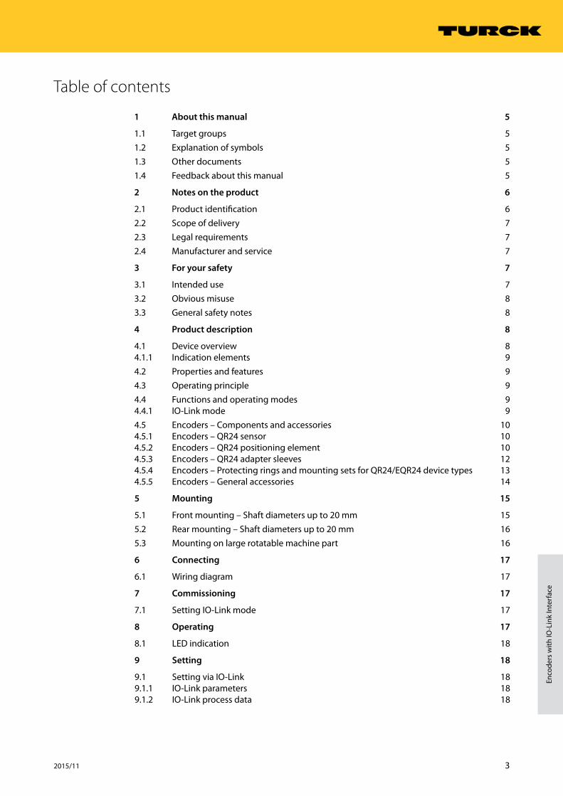
2 Notes on the product2.1 Product identification
NOTESensor, mounting element and positioning element of the encoders are available as a complete set or individually.
Ri 360 P1 Functional principle –
Positioning element/for shaft diameterP0 without positioning
elementP1 P1-Ri-QR24/20 mmP2 P2-Ri-QR24/14 mmP3 P3-Ri-QR24/12 mmP4 P4-Ri-QR24/10 mmP5 P5-Ri-QR24/6 mmP6 P6-Ri-QR24 / 3/8"P7 P7-Ri-QR24 / 1/4"P8 P8-Ri-QR24 / -
Measuring range
360 360°
Functional principleRi Rotary inductive
Ri 360 P1 – QR24 M1 – IOL X2 – H1 1 4 1
H1 1 4 1 Electrical connection
Assignment1 Standard assignment
Number of contacts4 4-pin M12 x 1
Connector type1 straight
Connector type H1 Male connector M12 x 1
QR24 M1 Design –
Mounting elementM0 w/o aluminum pro-
tective unitM1 with aluminum
protective unit
M2 Set M2-QR24(M1-QR24 + SP1-QR24)
M3 Set M3-QR24(M1-QR24 + SP2-QR24)
M4 Set M4-QR24(M1-QR24 + SP3-QR24)
DesignQR24 Standard housing
IOL X2 Electrical version –
Number of LEDsX2 2 × LED
OutputIOL IO-Link interface

7 2015/11
Enco
ders
with
IO-L
ink
Inte
rfac
e
2.2 Scope of delivery
The following are included in the scope of delivery: ■ Encoder – sensor ■ MT-QR24 mounting aid ■ Quick Start Guide ■ Optional: Positioning element and mounting element
2.3 Legal requirements
The device is subject to the following EC directives: ■ 2004/108/EC (electromagnetic compatibility) ■ 2011/65/EU (RoHS)
2.4 Manufacturer and service
Turck supports you in your projects – from the initial analysis right through to the commission-ing of your application. The Turck product database offers you several software tools for pro-gramming, configuring or commissioning, as well as data sheets and CAD files in many export formats. You can access the Product Database directly via the following address: www.turck.de/products
For further inquiries in Germany contact the Sales and Service Team on:Sales: +49 208 4952-380Technical: +49 208 4952-390
For overseas inquiries contact your national Turck representative.
Hans Turck GmbH & Co. KGWitzlebenstraße 745472 Mülheim an der RuhrGermany
3 For your safetyThe product is designed according to the state of the art technology. Residual hazards, howev-er, still exist. Observe the following warnings and safety regulations in order to prevent danger to persons and property. Turck accepts no liability for damage caused by failure to observe these warnings and safety instructions.
3.1 Intended use
The devices are designed for use in industrial automation applications. They only meet the EMC-requirements for these applications. The Ri360…-IOL rotary encoders with an IO-Link interface are used for measuring speeds and angle movements. To do this the devices detect mechanical rotary movements and convert them into a digital IO-Link telegram.The devices can be operated and parameterized via an IO-Link interface with IO-Link masters compliant with specification 1.1. Process and diagnostics data can be exchanged during opera-tion via IO-Link with the higher controller level.The devices must only be used as described in these instructions. Any other use is not in accor-dance with the intended use; Turck accepts no liability for any resulting damage.
8 Hans Turck GmbH & Co. KG | T +49 208 4952-0 | F +49 208 4952-264 | [email protected] | www.turck.com
Product description
3.2 Obvious misuse
Any use exceeding the maximum permissible speed of 800 rpm is not in accordance with the intended use. The devices are not safety components and must not be used for the protection of persons or property.
3.3 General safety instructions
■ The device must only be fitted, installed, set, operated and maintained by trained and quali-fied personnel.
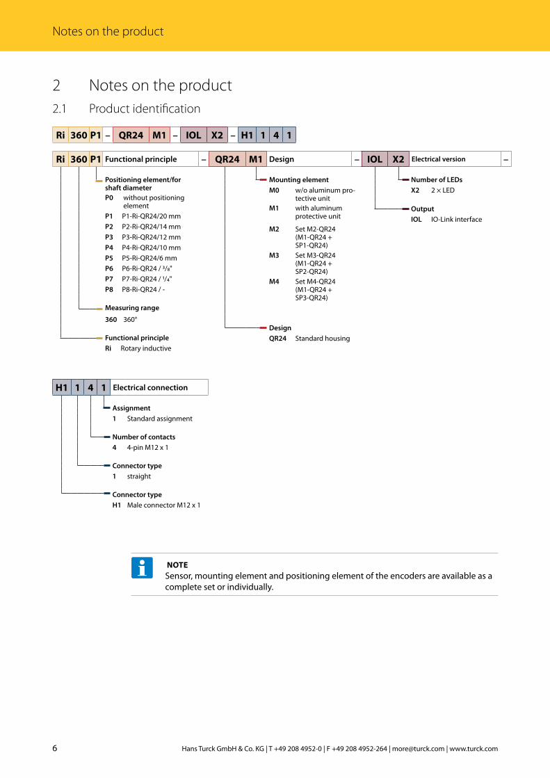
4 Product descriptionThe inductive encoders of the RI360P-QR24 series measure speeds and angle movements up to 360º. The sensor and the positioning element of the encoders are fully encapsulated and there-fore designed as two independent and fully sealed units with protection to IP69K, which work together without contact. The optionally available adapter sleeves and mounting elements enable either the front or the rear of the encoder sensors to be fitted to shafts with a diameter of up to 20 millimeters. A mounting element for mounting on large rotatable machine parts is also provided in the program. The devices are available as absolute encoders with different output functions and also as incremental encoders. A robust stainless steel EQR24 variant is available for use in the food and beverage industry.The QR24 encoders with an IO-Link interface can be connected via a standard 4-pole male con-nector and a 3-wire connection cable. The devices can be operated and set via IO-Link.
4.1 Device overview
ø 4.3
ø 65ø 74
24
15.3
81
10
42.3LED
ø 78 M12 x 1
ø 3.2
ø 42ø 20
120°
24
81
10
42.3
LED
ø 78 ø 22 ø 4.3 ø 65
M12 x 1
Fig. 1 QR24 encoder with sensor, P1 positioning ele-ment (optional) and protecting ring (optional)
Fig. 2 Encoder – sensor (front)
ø 42 M4 x 0.5 x 7.5
ø 3.2
ø 20
ø 52
ø 42 10
Fig. 3 Encoder – sensor (rear) Fig. 4 Encoder – positioning element P1
9 2015/11
Enco
ders
with
IO-L
ink
Inte
rfac
e
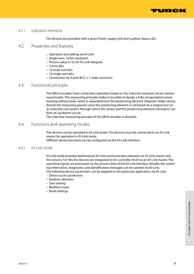
4.1.1 Indication elements
The devices are provided with a green Power supply LED and a yellow Status LED.
4.2 Properties and features
■ Operation and setting via IO-Link ■ Single-turn, 16-bit resolution ■ Process value in 32-bit IO-Link telegram ■ 3 error bits ■ 13 multi-turn bits ■ 16 single-turn bits ■ Connection via 4-pole M12 × 1 male connector
4.3 Functional principle
The QR24 encoders have contactless operation based on the inductive resonant circuit measur-ing principle. This measuring principle makes it possible to design a fully encapsulated sensor housing without seals, which is separated from the positioning element. Magnetic fields cannot disturb the measuring process since the positioning element is not based on a magnet but on an inductive coil system, through which the sensor and the positioning element (resonator) can form an oscillation circuit. The inductive measuring principle of the QR24 encoder is absolute.
4.4 Functions and operating modes
The devices can be operated in IO-Link mode. The devices must be connected to an IO-Link master for operation in IO-Link mode.Different device functions can be configured via the IO-Link interface.
4.4.1 IO-Link mode
IO-Link mode provides bidirectional IO-Link communication between an IO-Link master and the sensors. For this the devices are integrated in the controller level via an IO-Link master. The switching signals are processed via the process data of the IO-Link interface. Besides the switch-ing information, diagnostics and identification messages can be queried via IO-Link.The following device parameters can be adapted to the particular application via IO-Link: ■ Device access protection ■ Rotation direction ■ Zero setting ■ Multiturn reset ■ Reset settings
10 Hans Turck GmbH & Co. KG | T +49 208 4952-0 | F +49 208 4952-264 | [email protected] | www.turck.com
Product description
4.5 Encoders – components and accessories
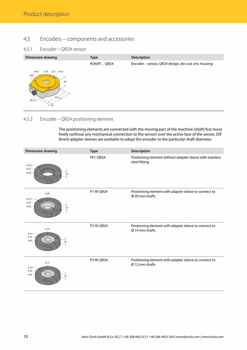
4.5.1 Encoder – QR24 sensor
Dimension drawing Type Description
24
81
10
42.3
LED
ø 78 ø 22 ø 4.3 ø 65
M12 x 1
Ri360P…-QR24 Encoder – sensor, QR24 design, die cast zinc housing
4.5.2 Encoder – QR24 positioning element
The positioning elements are connected with the moving part of the machine (shaft) but move freely (without any mechanical connection to the sensor) over the active face of the sensor. Dif-ferent adapter sleeves are available to adapt the encoder to the particular shaft diameter.
Dimension drawing Type Description
ø 3.2ø 52
ø 42 10
PE1-QR24 Positioning element without adapter sleeve with stainless steel fitting
ø 3.2
ø 20
ø 52
ø 42 10
P1-Ri-QR24 Positioning element with adapter sleeve to connect to Ø 20 mm shafts
ø 3.2ø 52
ø 42 10
ø 14P2-Ri-QR24 Positioning element with adapter sleeve to connect to
Ø 14 mm shafts
ø 3.2ø 52
ø 42 10
ø 12P3-Ri-QR24 Positioning element with adapter sleeve to connect to
Ø 12 mm shafts
11 2015/11
Enco
ders
with
IO-L
ink
Inte
rfac
e
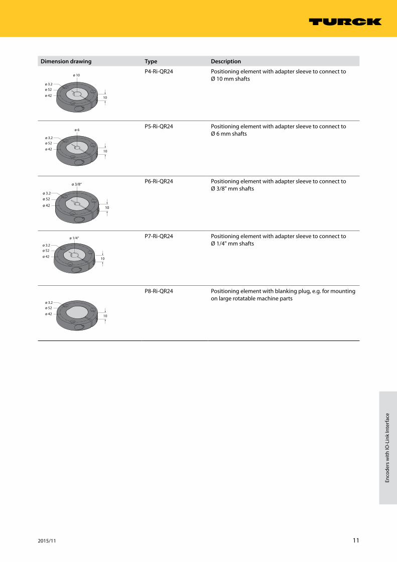
Dimension drawing Type Description
ø 3.2ø 52
ø 42 10
ø 10P4-Ri-QR24 Positioning element with adapter sleeve to connect to
Ø 10 mm shafts
ø 3.2ø 52
ø 42 10
ø 6P5-Ri-QR24 Positioning element with adapter sleeve to connect to
Ø 6 mm shafts
ø 3.2ø 52
ø 42 10
ø 3/8“ P6-Ri-QR24 Positioning element with adapter sleeve to connect to Ø 3/8" mm shafts
ø 3.2ø 52
ø 42 10
ø 1/4“ P7-Ri-QR24 Positioning element with adapter sleeve to connect to Ø 1/4" mm shafts
ø 3.2ø 52
ø 42 10
P8-Ri-QR24 Positioning element with blanking plug, e.g. for mounting on large rotatable machine parts
12 Hans Turck GmbH & Co. KG | T +49 208 4952-0 | F +49 208 4952-264 | [email protected] | www.turck.com
Product description
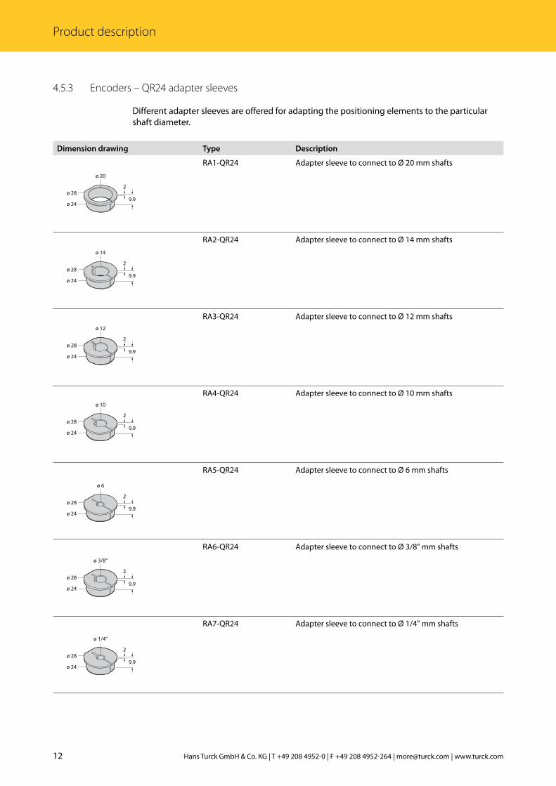
4.5.3 Encoders – QR24 adapter sleeves
Different adapter sleeves are offered for adapting the positioning elements to the particular shaft diameter.
Dimension drawing Type Description
ø 24
ø 282
9.9
ø 20
RA1-QR24 Adapter sleeve to connect to Ø 20 mm shafts
ø 24
ø 282
9.9
ø 14
RA2-QR24 Adapter sleeve to connect to Ø 14 mm shafts
ø 24
ø 282
9.9
ø 12
RA3-QR24 Adapter sleeve to connect to Ø 12 mm shafts
ø 24
ø 282
9.9
ø 10
RA4-QR24 Adapter sleeve to connect to Ø 10 mm shafts
ø 24
ø 282
9.9
ø 6
RA5-QR24 Adapter sleeve to connect to Ø 6 mm shafts
ø 24
ø 282
9.9
ø 3/8“
RA6-QR24 Adapter sleeve to connect to Ø 3/8" mm shafts
ø 24
ø 282
9.9
ø 1/4“
RA7-QR24 Adapter sleeve to connect to Ø 1/4" mm shafts
13 2015/11
Enco
ders
with
IO-L
ink
Inte
rfac
e
ø 24
ø 282
9.9
RA8-QR24 Blanking plug for mounting without adapter sleeve (e.g. mounting the positioning element on large rotatable machine parts)
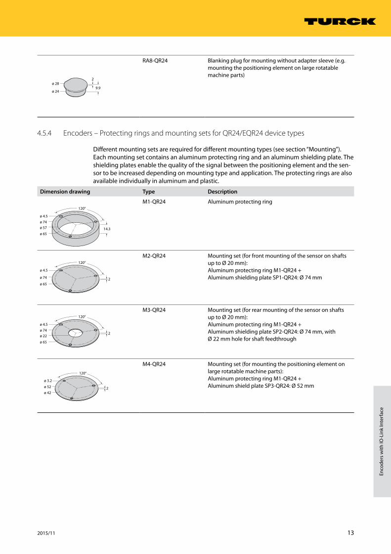
4.5.4 Encoders – Protecting rings and mounting sets for QR24/EQR24 device types
Different mounting sets are required for different mounting types (see section “Mounting”). Each mounting set contains an aluminum protecting ring and an aluminum shielding plate. The shielding plates enable the quality of the signal between the positioning element and the sen-sor to be increased depending on mounting type and application. The protecting rings are also available individually in aluminum and plastic.
Dimension drawing Type Description
ø 74ø 4.5
ø 65
ø 57
120°
14.3
M1-QR24 Aluminum protecting ring
ø 74
ø 4.5
ø 65
120°
2
M2-QR24 Mounting set (for front mounting of the sensor on shafts up to Ø 20 mm): Aluminum protecting ring M1-QR24 + Aluminum shielding plate SP1-QR24: Ø 74 mm
ø 74ø 4.5
ø 65
ø 22
120°
2
M3-QR24 Mounting set (for rear mounting of the sensor on shafts up to Ø 20 mm): Aluminum protecting ring M1-QR24 + Aluminum shielding plate SP2-QR24: Ø 74 mm, with Ø 22 mm hole for shaft feedthrough
ø 52
ø 3.2
ø 42
120°
2
M4-QR24 Mounting set (for mounting the positioning element on large rotatable machine parts): Aluminum protecting ring M1-QR24 + Aluminum shield plate SP3-QR24: Ø 52 mm
14 Hans Turck GmbH & Co. KG | T +49 208 4952-0 | F +49 208 4952-264 | [email protected] | www.turck.com
Product description
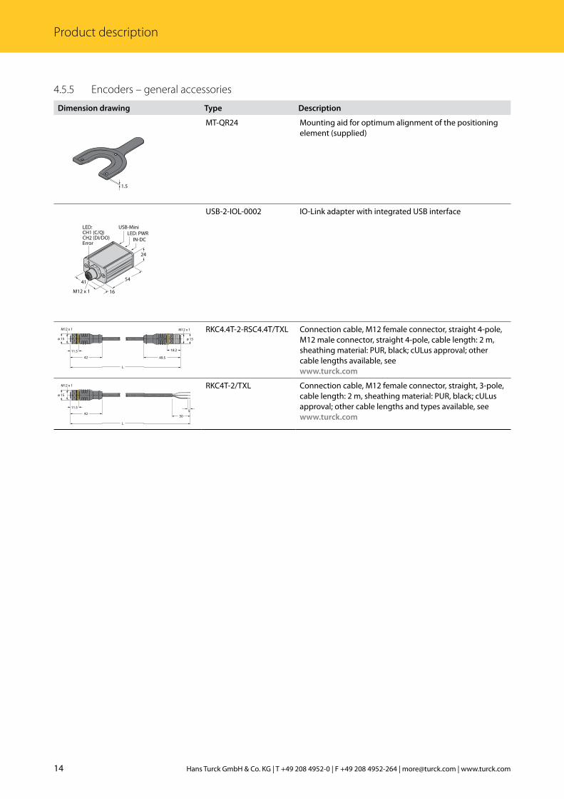
4.5.5 Encoders – general accessories
Dimension drawing Type Description
1.5
MT-QR24 Mounting aid for optimum alignment of the positioning element (supplied)
41
24
54
M12 x 1 16
USB-Mini
IN-DC
LED:CH1 (C/Q)CH2 (DI/DO)Error
LED: PWR
USB-2-IOL-0002 IO-Link adapter with integrated USB interface
L
42
11.5
ø 15
M12 x 1 M12 x 1
49.5
18.2
ø 15
RKC4.4T-2-RSC4.4T/TXL Connection cable, M12 female connector, straight 4-pole, M12 male connector, straight 4-pole, cable length: 2 m, sheathing material: PUR, black; cULus approval; other cable lengths available, see www.turck.com
L
42
11.5
ø 15
M12 x 1
505
RKC4T-2/TXL Connection cable, M12 female connector, straight, 3-pole, cable length: 2 m, sheathing material: PUR, black; cULus approval; other cable lengths and types available, see www.turck.com
15 2015/11
Enco
ders
with
IO-L
ink
Inte
rfac
e
5 Mounting The optionally available adapter sleeves and mounting elements enable the front or rear of the encoder sensors to be fitted to the shafts with a diameter of up to 20 millimeters. With large rotatable machine parts, the positioning element is screwed directly onto the machine part and not fitted on the shaft:
WARNINGImproper fixingPossible fatal injury from fast moving parts!
➤➤ Observe mounting instructions in all cases.➤➤ Check the secure seating of the positioning element, tightening torque: M = 0.6…0.8 Nm.
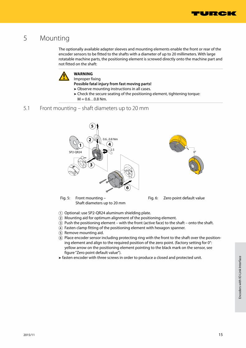
5.1 Front mounting – shaft diameters up to 20 mm
6
21
5
4
3
2.5
0.6...0.8 Nm
SP2-QR24 0°
Fig. 5: Front mounting – Shaft diameters up to 20 mm
Fig. 6: Zero point default value
1.Optional: use SP2-QR24 aluminum shielding plate.2.Mounting aid for optimum alignment of the positioning element.3.Push the positioning element – with the front (active face) to the shaft – onto the shaft.4.Fasten clamp fitting of the positioning element with hexagon spanner.5.Remove mounting aid. 6.Place encoder sensor including protecting ring with the front to the shaft over the position-
ing element and align to the required position of the zero point. (factory setting for 0°: yellow arrow on the positioning element pointing to the black mark on the sensor, see figure “Zero point default value”).
➤➤ fasten encoder with three screws in order to produce a closed and protected unit.
16 Hans Turck GmbH & Co. KG | T +49 208 4952-0 | F +49 208 4952-264 | [email protected] | www.turck.com
Mounting
5.2 Rear mounting – shaft diameters up to 20 mm
2
1
5
3
42.5
1.4...1.5 Nm
0.6…0.8 Nm0°
Fig. 7 Rear mounting – Shaft diameters up to 20 mm
Fig. 8 Zero point default value
1.Push the encoder sensor – with the rear to the shaft – onto the shaft and fasten with three screws.
2.Mounting aid for optimum alignment of the positioning element. 3.Push the positioning element onto the shaft and align to the required position of the zero
point. (factory setting for 0°: yellow arrow on the positioning element pointing to the black mark on the sensor, see figure “Zero point default value”).
4.Fasten clamp fitting of the positioning element with hexagon spanner. 5.Remove mounting aid.
➤➤ Optional: use protecting ring and SP1-QR24 aluminum shielding plate.
5.3 Mounting on large rotatable machine part
4
3
1
2
2.5
0.6...0.8 Nm0.6...0.8 NmSP3-QR24
0°
Fig. 9: Mounting on Large Rotatable Machine Part
Fig. 10 Zero point default value
1.If not yet present: Insert RA8-QR24 blanking plug into positioning element.2.Fasten clamp fitting of the positioning element with hexagon spanner.3.Optional: use SP3-QR24 shield plate.4.Fasten positioning element with three M3 countersunk screws (recommended: stainless
steel).➤➤ Depending on the application, mount the encoder and align to the required position of the zero point (factory setting for 0°: yellow arrow on the positioning element pointing to the black mark on the sensor, see figure “Zero point default value”).
17 2015/11
Enco
ders
with
IO-L
ink
Inte
rfac
e
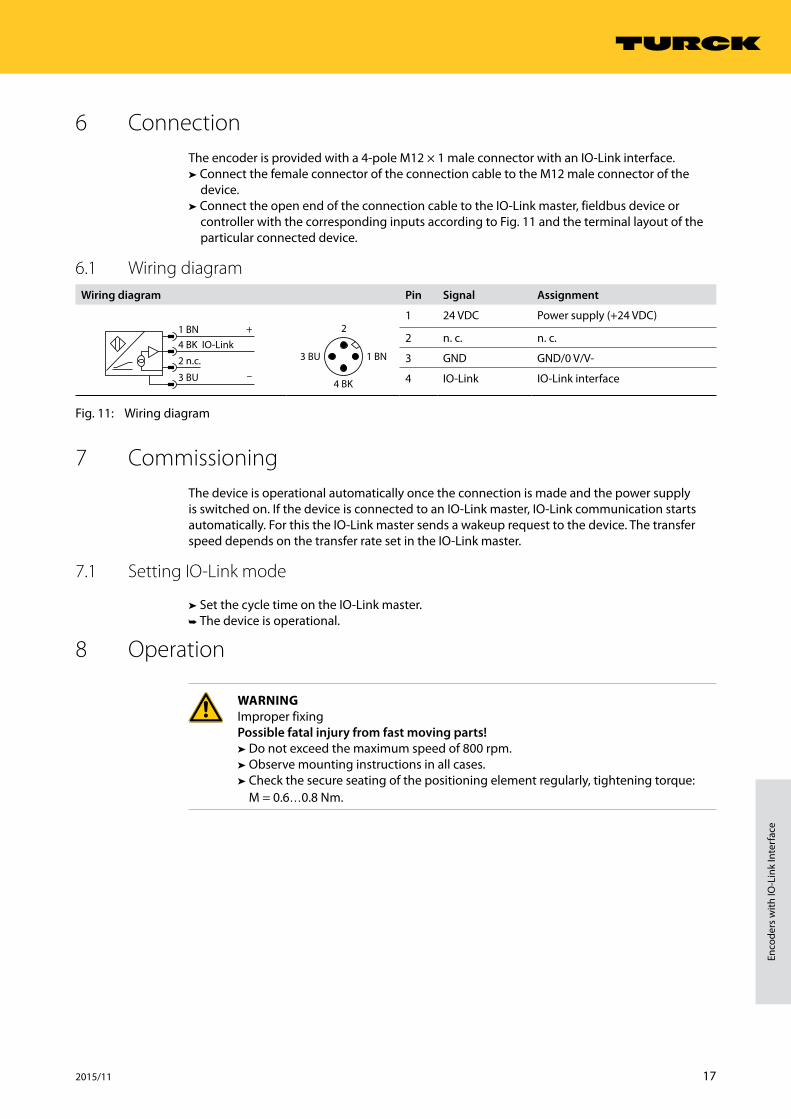
6 ConnectionThe encoder is provided with a 4-pole M12 × 1 male connector with an IO-Link interface.
➤➤ Connect the female connector of the connection cable to the M12 male connector of the device.
➤➤ Connect the open end of the connection cable to the IO-Link master, fieldbus device or controller with the corresponding inputs according to Fig. 11 and the terminal layout of the particular connected device.
6.1 Wiring diagramWiring diagram Pin Signal Assignment
–
+1 BN
3 BU
4 BK IO-Link
2 n.c.
4 BK
3 BU 1 BN
21 24 VDC Power supply (+24 VDC)
2 n. c. n. c.
3 GND GND/0 V/V-
4 IO-Link IO-Link interface
Fig. 11: Wiring diagram
7 CommissioningThe device is operational automatically once the connection is made and the power supply is switched on. If the device is connected to an IO-Link master, IO-Link communication starts automatically. For this the IO-Link master sends a wakeup request to the device. The transfer speed depends on the transfer rate set in the IO-Link master.
7.1 Setting IO-Link mode
➤➤ Set the cycle time on the IO-Link master.➤➥ The device is operational.
8 Operation
WARNINGImproper fixingPossible fatal injury from fast moving parts!
➤➤ Do not exceed the maximum speed of 800 rpm.➤➤ Observe mounting instructions in all cases.➤➤ Check the secure seating of the positioning element regularly, tightening torque: M = 0.6…0.8 Nm.
18 Hans Turck GmbH & Co. KG | T +49 208 4952-0 | F +49 208 4952-264 | [email protected] | www.turck.com
Setting
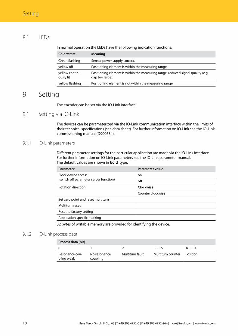
8.1 LEDs
In normal operation the LEDs have the following indication functions:
Color/state Meaning
Green flashing Sensor power supply correct.
yellow off Positioning element is within the measuring range.
yellow continu-ously lit
Positioning element is within the measuring range, reduced signal quality (e.g. gap too large).
yellow flashing Positioning element is not within the measuring range.
9 SettingThe encoder can be set via the IO-Link interface
9.1 Setting via IO-Link
The devices can be parameterized via the IO-Link communication interface within the limits of their technical specifications (see data sheet). For further information on IO-Link see the IO-Link commissioning manual (D900634).
9.1.1 IO-Link parameters
Different parameter settings for the particular application are made via the IO-Link interface. For further information on IO-Link parameters see the IO-Link parameter manual.The default values are shown in bold type.
Parameter Parameter value
Block device access (switch off parameter server function)
on
off
Rotation direction Clockwise
Counter clockwise
Set zero point and reset multiturn
Multiturn reset
Reset to factory setting
Application specific marking
32 bytes of writable memory are provided for identifying the device.
9.1.2 IO-Link process data
Process data (bit)
0 1 2 3…15 16…31
Resonance cou-pling weak
No resonance coupling
Multiturn fault Multiturn counter Position
19 2015/11
Enco
ders
with
IO-L
ink
Inte
rfac
e
10 TroubleshootingThe strength of the resonance coupling is indicated by an LED. Any faults are indicated via the LEDs.If the device does not function as expected, first check whether ambient interference is present. If there is no ambient interference present, check the connections of the device for faults.If there are no faults, there is a device malfunction. In this case, decommission the device and replace it with a new device of the same type.
11 MaintenanceEnsure that the plug connections and cables are always in good condition. The device is maintenance-free, clean dry if required.
12 RepairThe device must not be repaired by the user. The device must be decommissioned if it is faulty. Observe our return acceptance conditions when returning the device to Turck.
12.1 Returning devices
If a device has to be returned, bear in mind that only devices with a decontamination declara-tion will be accepted. This is available for download at http://www.turck.de/static/media/downloads/Declaration_of_decontamination_EN.pdf and must be completely filled in, and affixed securely and weather-proof to the outside of the packaging.
13 Decommissioning➤➤ Remove the connection cable from the power supply and/or processing units.➤➤ Remove the connection cable from the device.➤➤ Undo the connections of the device or if necessary the mounting aid for the mounting area.➤➤ Undo if necessary the connection of the device to the mounting aid.
14 DisposalThe devices are designed for installation in large-scale industrial installations and equipment. The devices must be disposed of correctly and must not be included in normal household garbage.
20 Hans Turck GmbH & Co. KG | T +49 208 4952-0 | F +49 208 4952-264 | [email protected] | www.turck.com
Technical data
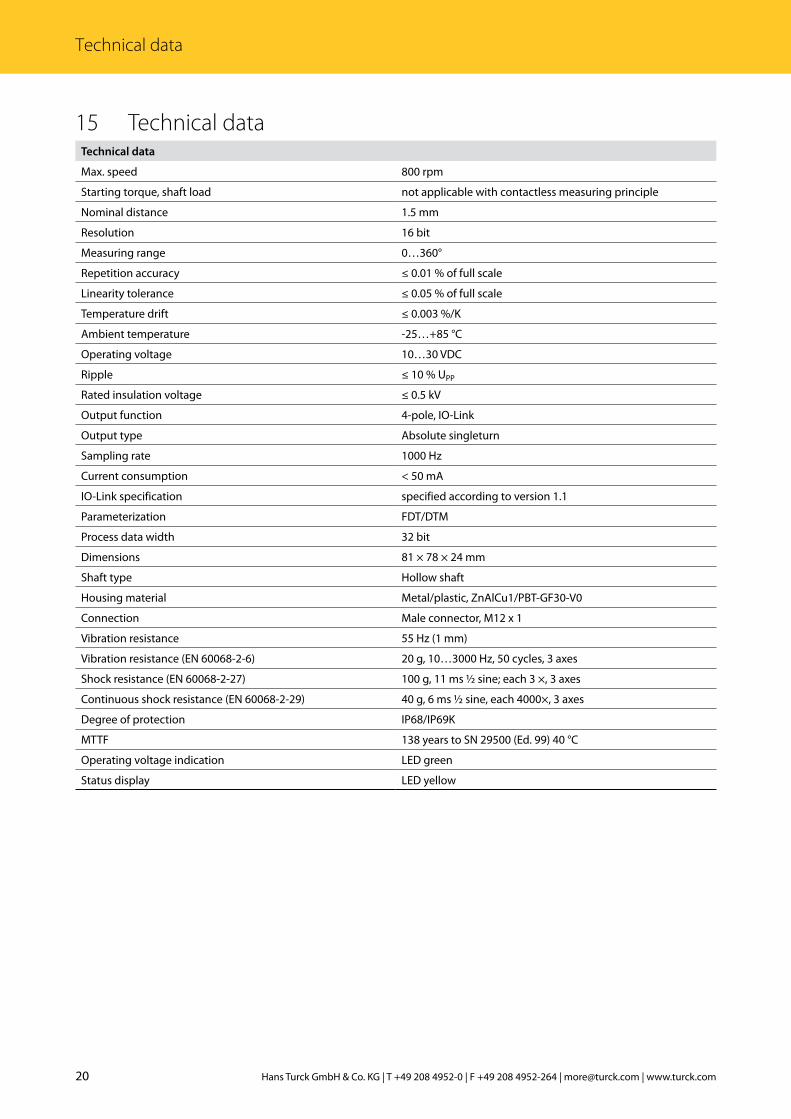
15 Technical dataTechnical data
Max. speed 800 rpm
Starting torque, shaft load not applicable with contactless measuring principle
Nominal distance 1.5 mm
Resolution 16 bit
Measuring range 0…360°
Repetition accuracy ≤ 0.01 % of full scale
Linearity tolerance ≤ 0.05 % of full scale
Temperature drift ≤ 0.003 %/K
Ambient temperature -25…+85 °C
Operating voltage 10…30 VDC
Ripple ≤ 10 % UPP
Rated insulation voltage ≤ 0.5 kV
Output function 4-pole, IO-Link
Output type Absolute singleturn
Sampling rate 1000 Hz
Current consumption < 50 mA
IO-Link specification specified according to version 1.1
Parameterization FDT/DTM
Process data width 32 bit
Dimensions 81 × 78 × 24 mm
Shaft type Hollow shaft
Housing material Metal/plastic, ZnAlCu1/PBT-GF30-V0
Connection Male connector, M12 x 1
Vibration resistance 55 Hz (1 mm)
Vibration resistance (EN 60068-2-6) 20 g, 10…3000 Hz, 50 cycles, 3 axes
Shock resistance (EN 60068-2-27) 100 g, 11 ms ½ sine; each 3 ×, 3 axes
Continuous shock resistance (EN 60068-2-29) 40 g, 6 ms ½ sine, each 4000×, 3 axes
Degree of protection IP68/IP69K
MTTF 138 years to SN 29500 (Ed. 99) 40 °C
Operating voltage indication LED green
Status display LED yellow

21 2015/11
Enco
ders
with
IO-L
ink
Inte
rfac
e

...with 28 subsidiaries and over 60 representations worldwide!
www.turck.com
D102213 | 2015/11
*D102213ßß1511*


![[Eddings david] (novel)_david_eddings_(ebook)_-_be(book_zz.org)](https://img.pdfslide.us/doc/110x75/55a1fbd21a28abc23d8b45f6/eddings-david-noveldavideddingsebook-bebookzzorg.jpg)