Embed Size (px)
Citation preview
Data Sheet
AFS60: Absolute Encoders Single turn, SSIAFM60: Absolute Encoders Multi-turn, SSI und SSI + Incremental
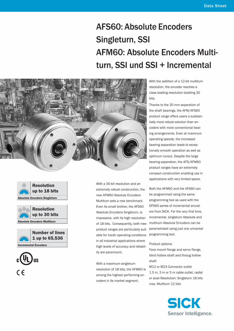
With a 30-bit resolution and an
extremely robust construction, the
new AFM60 Absolute Encoders
Multiturn sets a new benchmark.
Even its small brother, the AFS60
Absolute Encoders Singleturn, is
impressive, with its high resolution
of 18 bits. Consequently, both new
product ranges are particularly suit-
able for harsh operating conditions
in all industrial applications where
high levels of accuracy and reliabil-
ity are paramount.
With a maximum singleturn
resolution of 18 bits, the AFM60 is
among the highest performing en-
coders in its market segment.
With the addition of a 12-bit multiturn
resolution, the encoder reaches a
class leading resolution totalling 30
bits.
Thanks to the 30 mm separation of
the shaft bearings, the AFM/AFS60
product range offers users a substan-
tially more robust solution than en-
coders with more conventional bear-
ing arrangements. Even at maximum
operating speeds, the increased
bearing separation leads to excep-
tionally smooth operation as well as
optimum runout. Despite the large
bearing separation, the AFS/AFM60
product ranges have an extremely
compact construction enabling use in
applications with very limited space.
Both the AFM60 and the AFS60 can
be programmed using the same
programming tool as used with the
DFS60 series of incremental encod-
ers from SICK. For the very first time,
incremental, singleturn Absolute and
multiturn Absolute Encoders can be
parametrised using just one universal
programming tool.
Product options:
Face mount flange and servo flange,
blind hollow shaft and throug hollow
shaft
M12 or M23 Connector outlet
1.5 m, 3 m or 5 m cable outlet, radial
or axial Resolution: Singleturn 18 bits
max. Multiturn 12 bits
Resolution up to 18 bits
Absolute Encoders Singleturn
Resolution up to 30 bits
Absolute Encoders Multiturn
Number of lines1 up to 65,536
Incremental Encoders
2 A F S 6 0 / A F M 6 0 2 0 1 0 - 1 1Subject to change without notice
▀ Connector or cable outlet
▀ Protection class IP 67
▀ Electrical interface SSI or SSI + Incremental
▀ Resolution, number of incremental lines, TTL- or HTL-signal and offset programmable
Accessories Connection systems (page 28) Mounting systems (page 30)Programming Tool (page 27)
Pin allocation (page 26)
Resolution up to 18 bits
Absolute Encoders Singleturn
Resolution up 30 bits
Absolute Encoders Multiturn
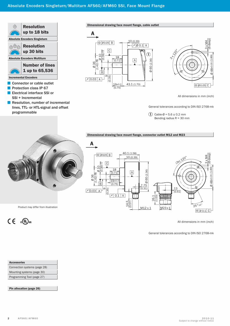
Absolute Encoders Singleturn/Multiturn AFS60/AFM60 SSI, Face Mount Flange
Product may differ from illustration
General tolerances according to DIN ISO 2768-mk
Dimensional drawing face mount flange, cable outlet
Dimensional drawing face mount flange, connector outlet M12 and M23
General tolerances according to DIN ISO 2768-mk
Cable-Ø = 5.6 ± 0.2 mmBending radius R = 30 mm
7.75(0.31)
M23 x 1
26.1
(1.0
3)
13(0.51)
All dimensions in mm (inch)
Ø 0.05 B
Ø 36
(1.4
2) f8
Ø 10
(0.3
9) f7
0.03 A
B
C
9(0
.35)
Ø 60
(2.3
6)
40.1 (1.58)10 (0.39)
A
0.1 A
14.5
(0.5
7)
M12 x 1
(3x) 120°
3 x
M4
(6-d
eep)
Ø 48
±0.0
5 (1
.89)
Ø 0.1 C
18(0.71)
19±0.3(0.75)
25°±2°
A
All dimensions in mm (inch)
Ø 60
(2.3
6)
Ø 0.05 B
0.03 A
B
C
Ø 36
(1.4
2) f8
Ø 10
(0.3
9) f7
9(0
.35)
18(0.71)
19±0.3(0.75)
43.1 (1.70)
A
10 (0.39)
Ø 0.1 A
3 x 1
20°
3 x
M4
(6-d
eep)
Ø 48
±0.0
5 (1
.89)
Ø 0.05 C
A
Number of lines1 up to 65,536
Incremental Encoders

3A F S 6 0 / A F M 6 02 0 1 0 - 1 1Subject to change without notice
AFS60/AFM60 SSI
Technical data to DIN 32878 AFS60/AFM60 face mount flange E B A
Mechanical dataShaft diameter 10 x 19 mmMass 1) 0.26 kgMoment of inertia to the rotor 6.2 gcm2
Operating speed 2) 9,000 min–1
Angular acceleration max. 5 x 10⁵ rad/s2
Operating torque at 20 °C 0.3 NcmStarting torque at 20 °C 0.5 NcmPermissible shaft movement Radial 80 N 80 N 80 N
Axial 40 N 40 N 40 NBearing lifetime 3 x 10⁹ revolutionsResistance To shocks 3) 50 g/6 ms 70 g/6 ms 60 g/6 ms
To vibration 4) 20 g/10 ... 2,000 Hz 30 g/10 ... 2,000 Hz 20 g/10 ... 2,000 Hz
Electrical dataCode type GrayCode sequence adjustable CW/CCWMeasuring step 360° number of lines 0.09° 0.01° 0.0014°Number of steps per revolution max. Singleturn and Multiturn 4096 32768 1 262144 1Number of lines 4096 Multiturn (AFM60)Error limits ± 0.2° ± 0.05° ± 0.03°Measuring step deviation Number of lines per revolution 1 … 399 ± 0.2° ± 0.08° ± 0.04°
Number of lines per revolution 400 … 40000 ± 0.2° ± 0.01° ± 0.008°Number of lines per revolution > 40000 ± 0.002°
Repeatability 0.002°Position sample time < 1 µsEMC 5)
Operating voltage 4.5 … 32 VPower consumption, no load 0.5 WInitialisation time 6) 50 msSignal line SSI 7) Clock +, Clock –, Data +, Data – SSI clock frequency 2 MHz;
or min. LOW level (Clock +): 500 ns 1 MHz 2 MHz 2 MHz
SET (electronic adjustment) H-active (L = 0 - 3 V; H = 4 - US V)CW/ CCW (counting sequence when turning) L-active (L = 0 - 1.5 V; H = 2.0 - US V)Incremental interface TTL/HTL/programmable (AFM60 SSI + Incremental)Number of lines per revolution 1/4 of number of SSI steps per revolutionMeasuring step 90° electric/number of linesReference signal 90° electric, gated with A and BMax. output frequency 300 kHz 600 kHz 820 kHzLoad current 30 mA
Environmental dataWorking temperature range 0 ... +85 °C –30 ... +100 °C –30 ... +100 °CStorage temperature range (without package) –40 ... +100 °C –40 ... +100 °C –40 ... +100 °CPermissible relative humidity 8) 90 %Protection class to IEC 60529 Shaft side IP 65 IP 65 IP 65
Housing side connector outlet 9) IP 67 IP 67 IP 67Housing side cable outlet IP 67 IP 67 IP 67
1) Based on encoders with a connector outlet2) Self-warming 3.3 k/1,000 min-1, when applying, note working temperature range3) To EN 60068-2-274) To EN 60068-2-65) To EN 61000-6-2 and EN 61000-6-36) Valid positional data can be read once this time has elapsed7) Signal lines via 12-pin encoder connector, electrically isolated from the housing, ie.
12-core cable8) Condensation of the optical scanning not permitted9) With mating connector fitted
1 Maximum speed consideration AFS60/AFM6
4 A F S 6 0 / A F M 6 0 2 0 1 0 - 1 1Subject to change without notice
Order information
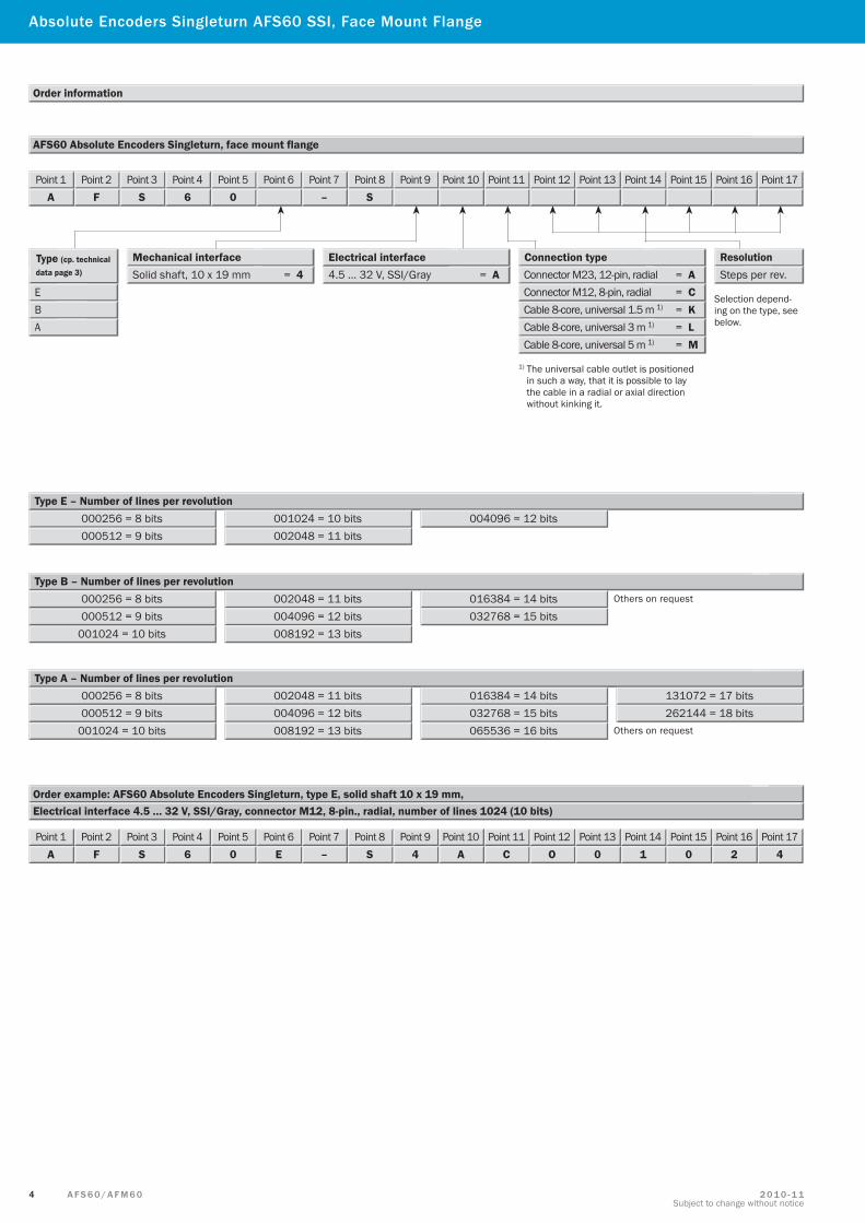
000256 = 8 bits Type E – Number of lines per revolution
Type B – Number of lines per revolution
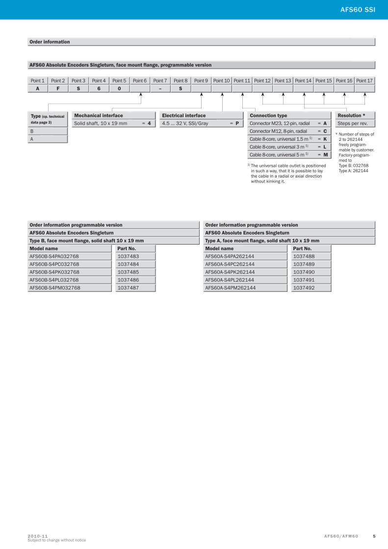
AFS60 Absolute Encoders Singleturn, face mount flange
Electrical interface 4.5 … 32 V, SSI/Gray, connector M12, 8-pin., radial, number of lines 1024 (10 bits)Order example: AFS60 Absolute Encoders Singleturn, type E, solid shaft 10 x 19 mm,
Type A – Number of lines per revolution
000512 = 9 bits001024 = 10 bits002048 = 11 bits
004096 = 12 bits
001024 = 10 bits
002048 = 11 bits004096 = 12 bits008192 = 13 bits
016384 = 14 bits032768 = 15 bits000512 = 9 bits
001024 = 10 bits
002048 = 11 bits004096 = 12 bits008192 = 13 bits
016384 = 14 bits032768 = 15 bits000512 = 9 bits065536 = 16 bits
131072 = 17 bits262144 = 18 bits
E
Type (cp. technical data page 3)
B
4.5 … 32 V, SSI/Gray = A Electrical interface Connection type
Connector M23, 12-pin, radial = A
Cable 8-core, universal 1.5 m 1) = K
Mechanical interface
A
Connector M12, 8-pin, radial = C
Cable 8-core, universal 3 m 1) = L Cable 8-core, universal 5 m 1) = M
Solid shaft, 10 x 19 mm = 4
Point 1A
Point 2F
Point 3S
Point 46
Point 50
Point 6 Point 7–
Point 8S
Point 9 Point 10 Point 11 Point 12 Point 13 Point 14 Point 15 Point 16 Point 17
Point 1A
Point 2F
Point 3S
Point 46
Point 50
Point 6E
Point 7–
Point 8S
Point 94
Point 10A
Point 11C
Point 12O
Point 130
Point 141
Point 150
Point 162
Point 174
000256 = 8 bits
000256 = 8 bits
1) The universal cable outlet is positioned in such a way, that it is possible to lay the cable in a radial or axial direction without kinking it.
Resolution
Selection depend-ing on the type, see below.
Steps per rev.
Absolute Encoders Singleturn AFS60 SSI, Face Mount Flange
Others on request
Others on request
5A F S 6 0 / A F M 6 02 0 1 0 - 1 1Subject to change without notice
AFS60 Absolute Encoders Singleturn, face mount flange, programmable version
Order information
Type (cp. technical data page 3)
B 4.5 … 32 V, SSI/Gray = P Electrical interface Connection type
Connector M23, 12-pin, radial = A
Cable 8-core, universal 1.5 m 1) = K
Mechanical interface
A Connector M12, 8-pin, radial = C
Cable 8-core, universal 3 m 1) = L Cable 8-core, universal 5 m 1) = M
Solid shaft, 10 x 19 mm = 4
Point 1A
Point 2F
Point 3S
Point 46
Point 50
Point 6 Point 7–
Point 8S
Point 9 Point 10 Point 11 Point 12 Point 13 Point 14 Point 15 Point 16 Point 17
* Number of steps of 2 to 262144 freely program- mable by customer. Factory-program- med to Type B: 032768 Type A: 262144
1) The universal cable outlet is positioned in such a way, that it is possible to lay the cable in a radial or axial direction without kinking it.
Order information programmable versionAFS60 Absolute Encoders SingleturnType B, face mount flange, solid shaft 10 x 19 mmModel name Part No.
10374831037484103748510374861037487
AFS60B-S4PA032768AFS60B-S4PC032768AFS60B-S4PK032768AFS60B-S4PL032768AFS60B-S4PM032768
Order information programmable versionAFS60 Absolute Encoders SingleturnType A, face mount flange, solid shaft 10 x 19 mmModel name Part No.
10374881037489103749010374911037492
AFS60A-S4PA262144AFS60A-S4PC262144AFS60A-S4PK262144AFS60A-S4PL262144AFS60A-S4PM262144
Resolution * Steps per rev.
AFS60 SSI
6 A F S 6 0 / A F M 6 0 2 0 1 0 - 1 1Subject to change without notice
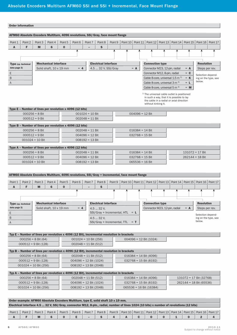
Order information
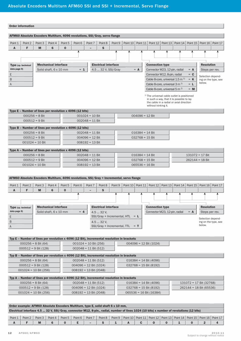
AFM60 Absolute Encoders Multiturn, 4096 revolutions, SSI/Gray, face mount flange
Point 1A
Point 2F
Point 3M
Point 46
Point 50
Point 6 Point 7–
Point 8S
Point 9 Point 10 Point 11 Point 12 Point 13 Point 14 Point 15 Point 16 Point 17
E
Type (cp. technical data page 3)
B
4.5 … 32 V, SSI/Gray = A Electrical interface Connection type
Connector M23, 12-pin, radial = A
Cable 8-core, universal 1.5 m 1) = K
Mechanical interface
A
Connector M12, 8-pin, radial = C
Cable 8-core, universal 3 m 1) = L Cable 8-core, universal 5 m 1) = M
Solid shaft, 10 x 19 mm = 4
1) The universal cable outlet is positioned in such a way, that it is possible to lay the cable in a radial or axial direction without kinking it.
Resolution
Selection depend-ing on the type, see below.
Steps per rev.
Absolute Encoders Multiturn AFM60 SSI and SSI + Incremental, Face Mount Flange
000256 = 8 Bit Type E – Number of lines per revolution x 4096 (12 bits)
000512 = 9 Bit001024 = 10 Bit002048 = 11 Bit
004096 = 12 Bit
Type B – Number of lines per revolution x 4096 (12 bits)
001024 = 10 Bit
002048 = 11 Bit004096 = 12 Bit008192 = 13 Bit
016384 = 14 Bit032768 = 15 Bit000512 = 9 Bit
000256 = 8 Bit
Type A – Number of lines per revolution x 4096 (12 bits)
001024 = 10 Bit
002048 = 11 Bit004096 = 12 Bit008192 = 13 Bit
016384 = 14 Bit032768 = 15 Bit000512 = 9 Bit065536 = 16 Bit
131072 = 17 Bit262144 = 18 Bit
000256 = 8 Bit
Electrical interface 4.5 … 32 V, SSI/Gray, connector M12, 8-pin., radial, number of lines 1024 (10 bits) x number of revolutions (12 bits)Order example: AFM60 Absolute Encoders Multiturn, type E, solid shaft 10 x 19 mm,
Point 1A
Point 2F
Point 3M
Point 46
Point 50
Point 6E
Point 7–
Point 8S
Point 94
Point 10A
Point 11C
Point 12O
Point 130
Point 141
Point 150
Point 162
Point 174
AFM60 Absolute Encoders Multiturn, 4096 revolutions, SSI/Gray + Incremental, face mount flange
000256 = 8 Bit (64) Typ E – Number of lines per revolution x 4096 (12 Bit), incremental resolution in brackets
000512 = 9 Bit (128)001024 = 10 Bit (256)002048 = 11 Bit (512)
004096 = 12 Bit (1024)
Typ B – Number of lines per revolution x 4096 (12 Bit), incremental resolution in brackets
001024 = 10 Bit (256)
002048 = 11 Bit (512)004096 = 12 Bit (1024)008192 = 13 Bit (2048)
016384 = 14 Bit (4096)032768 = 15 Bit (8192)000512 = 9 Bit (128)
000256 = 8 Bit (64)
Typ A – Number of lines per revolution x 4096 (12 Bit), incremental resolution in brackets
001024 = 10 Bit (256)
002048 = 11 Bit (512)004096 = 12 Bit (1024)008192 = 13 Bit (2048)
016384 = 14 Bit (4096)032768 = 15 Bit (8192)000512 = 9 Bit (128)
065536 = 16 Bit (16384)
131072 = 17 Bit (32768)262144 = 18 Bit (65536)
000256 = 8 Bit (64)
Point 1A
Point 2F
Point 3M
Point 46
Point 50
Point 6 Point 7–
Point 8S
Point 9 Point 10 Point 11 Point 12 Point 13 Point 14 Point 15 Point 16 Point 17
E
Type (cp. technical data page 3)
B
Electrical interface
4.5 … 32 V, SSI/Gray + Incremental, HTL = L
Connection type Connector M23, 12-pin, radial = A
Mechanical interface
A
Solid shaft, 10 x 19 mm = 4
Selection depend-ing on the type, see below.
Resolution Steps per rev.
4.5 … 32 V, SSI/Gray + Incremental, TTL = T

7A F S 6 0 / A F M 6 02 0 1 0 - 1 1Subject to change without notice
Order information
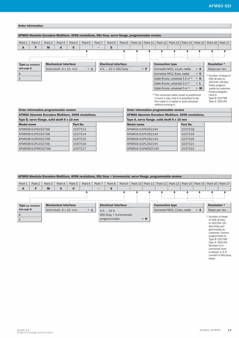
AFM60 Absolute Encoders Multiturn, 4096 revolutions, SSI/Gray, face mount flange, programmable version
Order information programmable versionAFM60 Absolute Encoders Multiturn, 4096 revolutions,Type B, face mount flange, solid shaft 10 x 19 mmModel name Part No.
10375031037504103750510375061037507
AFM60B-S4PA032768AFM60B-S4PC032768AFM60B-S4PK032768AFM60B-S4PL032768AFM60B-S4PM032768
Order information programmable versionAFM60 Absolute Encoders Multiturn, 4096 revolutions,Type A, face mount flange, solid shaft 10 x 19 mmModel name Part No.
10375081037509103751010375111037512
AFM60A-S4PA262144AFM60A-S4PC262144AFM60A-S4PK262144AFM60A-S4PL262144AFM60A-S4PM262144
Point 1A
Point 2F
Point 3M
Point 46
Point 50
Point 6 Point 7–
Point 8S
Point 9 Point 10 Point 11 Point 12 Point 13 Point 14 Point 15 Point 16 Point 17
Type (cp. technical data page 3)
B 4.5 … 32 V, SSI/Gray = P Electrical interface Connection type
Connector M23, 12-pin, radial = A
Cable 8-core, universal 1.5 m 1) = K
Mechanical interface
A Connector M12, 8-pin, radial = C
Cable 8-core, universal 3 m 1) = L Cable 8-core, universal 5 m 1) = M
Solid shaft, 10 x 19 mm = 4
1) The universal cable outlet is positioned in such a way, that it is possible to lay the cable in a radial or axial direction without kinking it.
* Number of steps of 256 (8 bits) to 262144 (18 bits) freely program- mable by customer. Factory-program- med to Type B: 032768 Type A: 262144
Resolution * Steps per rev.
AFM60 SSI
4.5 … 32 V, SSI/Gray + Incremental, programmable = R
Point 1A
Point 2F
Point 3M
Point 46
Point 50
Point 6 Point 7–
Point 8S
Point 9 Point 10 Point 11 Point 12 Point 13 Point 14 Point 15 Point 16 Point 17
AFM60 Absolute Encoders Multiturn, 4096 revolutions, SSI/Gray + Incremental, face mount flange, programmable version
Type (cp. technical data page 3)
B
Electrical interface Connection type Connector M23, 12-pin, radial = A
Mechanical interface
A
Solid shaft, 10 x 19 mm = 4
* Number of steps of 256 (8 bits) to 262144 (18 bits freely pro-grammable by customer. Factory-programmed to Type B: 032768 Type A: 262144; Number of in-cremental lines is always 1/4 of number of SSI/Gray steps.
Resolution * Steps per rev.
8 A F S 6 0 / A F M 6 0 2 0 1 0 - 1 1Subject to change without notice
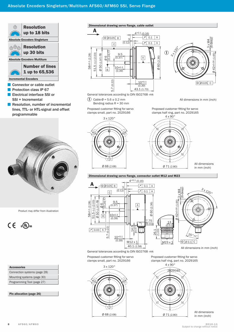
Absolute Encoders Singleturn/Multiturn AFS60/AFM60 SSI, Servo Flange
Accessories Connection systems (page 28) Mounting systems (page 30)Programming Tool (page 27)
Pin allocation (page 26)
Product may differ from illustration
Ø 0.05 B
C
B
A
Ø 0.05 C
58±0
.1 (2
.28)
51.5
–0.2
(2.0
3)
Ø 50
(1.9
7) f8
Ø 6
(0.2
4) f7
9.5(0.37)
5.7
(0.2
2)
10±0.3(0.39)
10+0.1
(0.39)43.1 (1.70)
Ø 60
(2.3
6)
4+0.1 (0.16)
3(0.12)
0.1 A
0.1 A
3 x 1
20° 3
x M
4(6
-dee
p)Ø
42±0
.05
(1.6
5)
All dimensions in mm (inch)
A
3 x 120° 4 x 90°
Ø 68 (2.68) Ø 71 (2.80)All dimensionsin mm (inch)
Dimensional drawing servo flange, cable outlet
Dimensional drawing servo flange, connector outlet M12 and M23
Proposed customer fitting for servo clamps small, part no. 2029166
Proposed customer fitting for servo clamps half ring, part no. 2029165
Proposed customer fitting for servoclamps small, part no. 2029166
General tolerances according to DIN ISO2768 -mk
Proposed customer fitting for servo clamps half ring, part no. 2029165
General tolerances according to DIN ISO2768 -mk
2029165
Cable-Ø = 5.6 ± 0.2 mmBending radius R = 30 mm
Ø 0.05 B
C
0.03 A
B
A
0.1 A
0.1 A
Ø 0.1 C
58±0
.1 (2
.28)
51.5
–0.2
(2.0
3)Ø
50 (1
.97)
f8Ø
6 (0
.24)
f75.
7 (0
.22)
9.5(0.37)
10±0.3(0.39)
10+0.1
(0.39)
4+0.1 (0.16)
3(0.12)
7.75(0.31)
Ø 60
(2.3
6)
M12 x 140.1 (1.58)
14.5
(0.5
7)
26.1
(1.0
3)
13(0.51)
M23 x 1
Ø 42
±0.0
5 (1
.65)
3 x
M4
(6-d
eep) 3 x 120°
25°±2°
All dimensions in mm (inch)
A
3 x 120° 4 x 90°
Ø 68 (2.68) Ø 71 (2.80)All dimensionsin mm (inch)
▀ Connector or cable outlet
▀ Protection class IP 67
▀ Electrical interface SSI or SSI + Incremental
▀ Resolution, number of incremental lines, TTL- or HTL-signal and offset programmable
Resolution up to 18 bits
Absolute Encoders Singleturn
Resolution up 30 bits
Absolute Encoders Multiturn
Number of lines1 up to 65,536
Incremental Encoders

9A F S 6 0 / A F M 6 02 0 1 0 - 1 1Subject to change without notice
AFS60/AFM60 SSI
Technical data to DIN 32878 AFS60/AFM60 servo flange E B A
Mechanical dataShaft diameter 6 x 10 mmMass 1) 0.26 kgMoment of inertia to the rotor 6.2 gcm2
Operating speed 2) 9,000 min–1
Angular acceleration max. 5 x 10⁵ rad/s2
Operating torque at 20 °C 0.3 NcmStarting torque at 20 °C 0.5 NcmPermissible shaft movement Radial 80 N 80 N 80 N
Axial 40 N 40 N 40 NBearing lifetime 3 x 10⁹ revolutionsResistance To shocks 3) 50 g/6 ms 70 g/6 ms 60 g/6 ms
To vibration 4) 20 g/10 ... 2,000 Hz 30 g/10 ... 2,000 Hz 20 g/10 ... 2,000 Hz
Electrical dataCode type GrayCode sequence adjustable CW/CCWMeasuring step 360° number of lines 0.09° 0.01° 0.0014°Number of steps per revolution max. Singleturn and Multiturn 4096 32768 1 262144 1Number of lines 4096 Multiturn (AFM60)Error limits ± 0.2° ± 0.05° ± 0.03°Measuring step deviation Number of lines per revolution 1 … 399 ± 0.2° ± 0.08° ± 0.04°
Number of lines per revolution 400 … 40000 ± 0.2° ± 0.01° ± 0.008°Number of lines per revolution > 40000 ± 0.002°
Repeatability 0.002°Position sample time < 1 µsEMC 5)
Operating voltage 4.5 … 32 VPower consumption, no load 0.5 WInitialisation time 6) 50 msSignal line SSI 7) Clock +, Clock –, Data +, Data – SSI clock frequency 2 MHz;
or min. LOW level (Clock +): 500 ns 1 MHz 2 MHz 2 MHz
SET (electronic adjustment) H-active (L = 0 - 3 V; H = 4 - US V)CW/ CCW (counting sequence when turning) L-active (L = 0 - 1.5 V; H = 2.0 - US V)Incremental interface TTL/HTL/programmable (AFM60 SSI + Incremental)Number of lines per revolution 1/4 of number of SSI steps per revolutionMeasuring step 90° electric/number of linesReference signal 90° electric, gated with A and BMax. output frequency 300 kHz 600 kHz 820 kHzLoad current 30 mA
Environmental dataWorking temperature range 0 ... +85 °C –30 ... +100 °C –30 ... +100 °CStorage temperature range (without package) –40 ... +100 °C –40 ... +100 °C –40 ... +100 °CPermissible relative humidity 8) 90 %Protection class to IEC 60529 Shaft side IP 65 IP 65 IP 65
Housing side connector outlet 9) IP 67 IP 67 IP 67Housing side cable outlet IP 67 IP 67 IP 67
1) Based on encoders with a connector outlet2) Self-warming 3.3 k/1,000 min-1, when applying, note working temperature range3) To EN 60068-2-274) To EN 60068-2-65) To EN 61000-6-2 and EN 61000-6-36) Valid positional data can be read once this time has elapsed7) Signal lines via 12-pin encoder connector, electrically isolated from the housing, ie.
12-core cable8) Condensation of the optical scanning not permitted9) With mating connector fitted
1 Maximum speed consideration AFS60/AFM6
1 0 A F S 6 0 / A F M 6 0 2 0 1 0 - 1 1Subject to change without notice
Order information
AFS60 Absolute Encoders Singleturn, servo flange
Electrical interface 4.5 … 32 V, SSI/Gray, connector M12, 8-pin., radial, number of lines 1024 (10 bits)Order example: AFS60 Absolute Encoders Singleturn, type E, solid shaft 6 x 10 mm,
000256 = 8 bits Type E – Number of lines per revolution
Type B – Number of lines per revolution
Type A – Number of lines per revolution
000512 = 9 bits001024 = 10 bits002048 = 11 bits
004096 = 12 bits
001024 = 10 bits
002048 = 11 bits004096 = 12 bits008192 = 13 bits
016384 = 14 bits032768 = 15 bits000512 = 9 bits
001024 = 10 bits
002048 = 11 bits004096 = 12 bits008192 = 13 bits
016384 = 14 bits032768 = 15 bits000512 = 9 bits065536 = 16 bits
131072 = 17 bits262144 = 18 bits
E
Type (cp. technical data page 9)
B
4.5 … 32 V, SSI/Gray = A Electrical interface Mechanical interface
A
Connection type Connector M23, 12-pin, radial = A
Cable 8-core, universal 1.5 m 1) = K Connector M12, 8-pin, radial = C
Cable 8-core, universal 3 m 1) = L Cable 8-core, universal 5 m 1) = M
Solid shaft, 6 x 10 mm = 1
Point 1A
Point 2F
Point 3S
Point 46
Point 50
Point 6 Point 7–
Point 8S
Point 9 Point 10 Point 11 Point 12 Point 13 Point 14 Point 15 Point 16 Point 17
Point 1A
Point 2F
Point 3S
Point 46
Point 50
Point 6E
Point 7–
Point 8S
Point 91
Point 10A
Point 11C
Point 12O
Point 130
Point 141
Point 150
Point 162
Point 174
000256 = 8 bits
000256 = 8 bits
1) The universal cable outlet is positioned in such a way, that it is possible to lay the cable in a radial or axial direction without kinking it.
Resolution
Selection depend-ing on the type, see below.
Steps per rev.
Absolute Encoders Singleturn AFS60 SSI, Servo Flange
Others on request
Others on request

1 1A F S 6 0 / A F M 6 02 0 1 0 - 1 1Subject to change without notice
Order information
AFS60 Absolute Encoders Singleturn, servo flange, programmable version
Type (cp. technical data page 9)
B 4.5 … 32 V, SSI/Gray = P Electrical interface Mechanical interface
A
Solid shaft, 6 x 10 mm = 1
Point 1A
Point 2F
Point 3S
Point 46
Point 50
Point 6 Point 7–
Point 8S
Point 9 Point 10 Point 11 Point 12 Point 13 Point 14 Point 15 Point 16 Point 17
Connection type Connector M23, 12-pin, radial = A
Cable 8-core, universal 1.5 m 1) = K Connector M12, 8-pin, radial = C
Cable 8-core, universal 3 m 1) = L Cable 8-core, universal 5 m 1) = M
1) The universal cable outlet is positioned in such a way, that it is possible to lay the cable in a radial or axial direction without kinking it.
Order information programmable versionAFS60 Absolute Encoders SingleturnType B, servo flange, solid shaft 6 x 10 mmModel name Part No.
10374931037494103749510374961037497
AFS60B-S1PA032768AFS60B-S1PC032768AFS60B-S1PK032768AFS60B-S1PL032768AFS60B-S1PM032768
Order information programmable versionAFS60 Absolute Encoders SingleturnType A, servo flange, solid shaft 6 x 10 mmModel name Part No.
10374981037499103750010375011037502
AFS60A-S1PA262144AFS60A-S1PC262144AFS60A-S1PK262144AFS60A-S1PL262144AFS60A-S1PM262144
* Number of steps of 2 to 262144 freely program- mable by customer. Factory-program- med to Type B: 032768 Type A: 262144
Resolution * Steps per rev.
AFS60 SSI
1 2 A F S 6 0 / A F M 6 0 2 0 1 0 - 1 1Subject to change without notice
Absolute Encoders Multiturn AFM60 SSI and SSI + Incremental, Servo Flange
Order information
AFM60 Absolute Encoders Multiturn, 4096 revolutions, SSI/Gray, servo flange
Point 1A
Point 2F
Point 3M
Point 46
Point 50
Point 6 Point 7–
Point 8S
Point 9 Point 10 Point 11 Point 12 Point 13 Point 14 Point 15 Point 16 Point 17
E
Type (cp. technical data page 9)
B
4.5 … 32 V, SSI/Gray = A Electrical interface Connection type
Connector M23, 12-pin, radial = A
Cable 8-core, universal 1.5 m 1) = K
Mechanical interface
A
Connector M12, 8-pin, radial = C
Cable 8-core, universal 3 m 1) = L Cable 8-core, universal 5 m 1) = M
Solid shaft, 6 x 10 mm = 1
1) The universal cable outlet is positioned in such a way, that it is possible to lay the cable in a radial or axial direction without kinking it.
Resolution
Selection depend-ing on the type, see below.
Steps per rev.
000256 = 8 Bit Type E – Number of lines per revolution x 4096 (12 bits)
000512 = 9 Bit001024 = 10 Bit002048 = 11 Bit
004096 = 12 Bit
Type B – Number of lines per revolution x 4096 (12 bits)
001024 = 10 Bit
002048 = 11 Bit004096 = 12 Bit008192 = 13 Bit
016384 = 14 Bit032768 = 15 Bit000512 = 9 Bit
000256 = 8 Bit
Type A – Number of lines per revolution x 4096 (12 bits)
001024 = 10 Bit
002048 = 11 Bit004096 = 12 Bit008192 = 13 Bit
016384 = 14 Bit032768 = 15 Bit000512 = 9 Bit065536 = 16 Bit
131072 = 17 Bit262144 = 18 Bit
000256 = 8 Bit
Electrical interface 4.5 … 32 V, SSI/Gray, connector M12, 8-pin., radial, number of lines 1024 (10 bits) x number of revolutions (12 bits)Order example: AFM60 Absolute Encoders Multiturn, type E, solid shaft 6 x 10 mm,
Point 1A
Point 2F
Point 3M
Point 46
Point 50
Point 6E
Point 7–
Point 8S
Point 91
Point 10A
Point 11C
Point 12O
Point 130
Point 141
Point 150
Point 162
Point 174
AFM60 Absolute Encoders Multiturn, 4096 revolutions, SSI/Gray + Incremental, servo flange
000256 = 8 Bit (64) Typ E – Number of lines per revolution x 4096 (12 Bit), incremental resolution in brackets
000512 = 9 Bit (128)001024 = 10 Bit (256)002048 = 11 Bit (512)
004096 = 12 Bit (1024)
Typ B – Number of lines per revolution x 4096 (12 Bit), incremental resolution in brackets
001024 = 10 Bit (256)
002048 = 11 Bit (512)004096 = 12 Bit (1024)008192 = 13 Bit (2048)
016384 = 14 Bit (4096)032768 = 15 Bit (8192)000512 = 9 Bit (128)
000256 = 8 Bit (64)
Typ A – Number of lines per revolution x 4096 (12 Bit), incremental resolution in brackets
001024 = 10 Bit (256)
002048 = 11 Bit (512)004096 = 12 Bit (1024)008192 = 13 Bit (2048)
016384 = 14 Bit (4096)032768 = 15 Bit (8192)000512 = 9 Bit (128)
065536 = 16 Bit (16384)
131072 = 17 Bit (32768)262144 = 18 Bit (65536)
000256 = 8 Bit (64)
Point 1A
Point 2F
Point 3M
Point 46
Point 50
Point 6 Point 7–
Point 8S
Point 9 Point 10 Point 11 Point 12 Point 13 Point 14 Point 15 Point 16 Point 17
E
Type (cp. technical data page 9)
B
Electrical interface
4.5 … 32 V, SSI/Gray + Incremental, HTL = L
Connection type Connector M23, 12-pin, radial = A
Mechanical interface
A
Solid shaft, 6 x 10 mm = 4
Selection depend-ing on the type, see below.
Resolution Steps per rev.
4.5 … 32 V, SSI/Gray + Incremental, TTL = T
1 3A F S 6 0 / A F M 6 02 0 1 0 - 1 1Subject to change without notice
Order information programmable versionAFM60 Absolute Encoders Multiturn, 4096 revolutions,Type B, servo flange, solid shaft 6 x 10 mmModel name Part No.
10375131037514103751510375161037517
AFM60B-S1PA032768AFM60B-S1PC032768AFM60B-S1PK032768AFM60B-S1PL032768AFM60B-S1PM032768
Order information programmable versionAFM60 Absolute Encoders Multiturn, 4096 revolutions,Type A, servo flange, solid shaft 6 x 10 mmModel name Part No.
10375181037519103752010375211037522
AFM60A-S1PA262144AFM60A-S1PC262144AFM60A-S1PK262144AFM60A-S1PL262144AFM60A-S1PM262144
AFM60 SSI
AFM60 Absolute Encoders Multiturn, 4096 revolutions, SSI/Gray, servo flange, programmable version
Point 1A
Point 2F
Point 3M
Point 46
Point 50
Point 6 Point 7–
Point 8S
Point 9 Point 10 Point 11 Point 12 Point 13 Point 14 Point 15 Point 16 Point 17
Type (cp. technical data page 9)
B 4.5 … 32 V, SSI/Gray = P Electrical interface Connection type
Connector M23, 12-pin, radial = A
Cable 8-core, universal 1.5 m 1) = K
Mechanical interface
A Connector M12, 8-pin, radial = C
Cable 8-core, universal 3 m 1) = L Cable 8-core, universal 5 m 1) = M
Solid shaft, 6 x 10 mm = 1
1) The universal cable outlet is positioned in such a way, that it is possible to lay the cable in a radial or axial direction without kinking it.
* Number of steps of 256 (8 bits) to 262144 (18 bits) freely program- mable by customer. Factory-program- med to Type B: 032768 Type A: 262144
Resolution * Steps per rev.
4.5 … 32 V, SSI/Gray + Incremental, programmable = R
Point 1A
Point 2F
Point 3M
Point 46
Point 50
Point 6 Point 7–
Point 8S
Point 9 Point 10 Point 11 Point 12 Point 13 Point 14 Point 15 Point 16 Point 17
AFM60 Absolute Encoders Multiturn, 4096 revolutions, SSI/Gray + Incremental, servo flange, programmable version
Type (cp. technical data page 9)
B
Electrical interface Connection type Connector M23, 12-pin, radial = A
Mechanical interface
A
Solid shaft, 6 x 10 mm = 1
* Number of steps of 256 (8 bits) to 262144 (18 bits freely pro-grammable by customer. Factory-programmed to Type B: 032768 Type A: 262144; Number of in-cremental lines is always 1/4 of number of SSI/Gray steps.
Resolution * Steps per rev.
Order information
1 4 A F S 6 0 / A F M 6 0 2 0 1 0 - 1 1Subject to change without notice
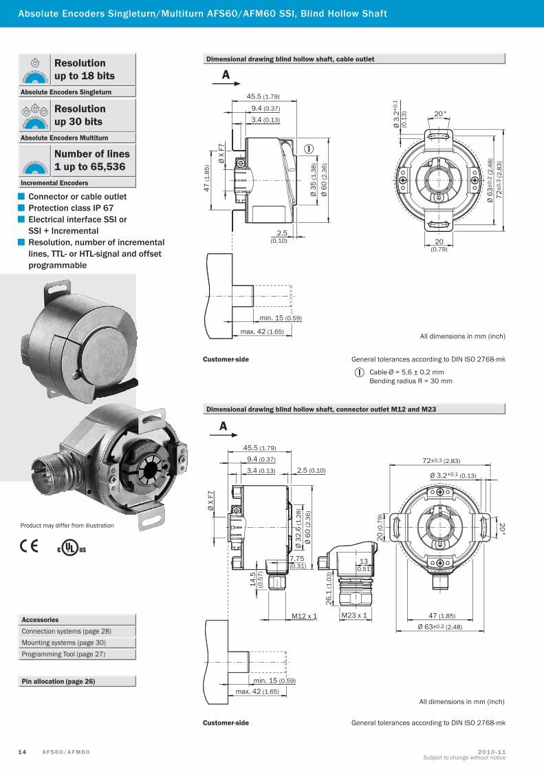
Absolute Encoders Singleturn/Multiturn AFS60/AFM60 SSI, Blind Hollow Shaft
Accessories Connection systems (page 28) Mounting systems (page 30)Programming Tool (page 27)
Pin allocation (page 26)
Product may differ from illustration
Cable-Ø = 5.6 ± 0.2 mmBending radius R = 30 mm
Customer-side General tolerances according to DIN ISO 2768-mk
Dimensional drawing blind hollow shaft, cable outlet
Dimensional drawing blind hollow shaft, connector outlet M12 and M23
Customer-side General tolerances according to DIN ISO 2768-mk
45.5 (1.79)
9.4 (0.37)
3.4 (0.13)
Ø X
F7
47 (1
.85)
Ø 35
(1.3
8)
Ø 60
(2.3
6)
2.5(0.10)
min. 15 (0.59)
Ø 3.
2+0.
1
(0.1
3) 20°
20(0.79)
Ø 63
±0.2
(2.4
8)72
±0.3
(2.8
3)
max. 42 (1.65)All dimensions in mm (inch)
A
45.5 (1.79)
9.4 (0.37)
3.4 (0.13)
Ø X
F7
2.5 (0.10)
Ø 60
(2.3
6)
min. 15 (0.59)
max. 42 (1.65)
14.5
(0.5
7)
M12 x 1
Ø 32
.6 (1
.28)
7.75(0.31)
26.1
(1.0
3)
13(0.51)
M23 x 1
72±0.3 (2.83)
Ø 3.2+0.1 (0.13)
20°
20 (0
.79)
47 (1.85)
Ø 63±0.2 (2.48)
All dimensions in mm (inch)
A
▀ Connector or cable outlet
▀ Protection class IP 67
▀ Electrical interface SSI or SSI + Incremental
▀ Resolution, number of incremental lines, TTL- or HTL-signal and offset programmable
Resolution up to 18 bits
Absolute Encoders Singleturn
Resolution up 30 bits
Absolute Encoders Multiturn
Number of lines1 up to 65,536
Incremental Encoders
1 5A F S 6 0 / A F M 6 02 0 1 0 - 1 1Subject to change without notice
AFS60/AFM60 SSI
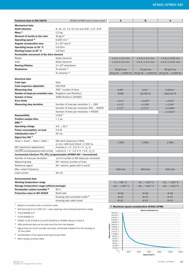
Technical data to DIN 32878 AFS60/AFM60 blind hollow shaft E B A
Mechanical dataShaft diameter 8, 10, 12, 14, 15 mm and 3/8", 1/2", 5/8"Mass 1) 0.2 kgMoment of inertia to the rotor 40 gcm2
Operating speed 2) 6,000 min–1
Angular acceleration max. 5 x 10⁵ rad/s2
Operating torque at 20 °C 0.6 NcmStarting torque at 20 °C 0.8 NcmPermissible movement of the drive elementRadial Static/dynamic ± 0.3 /± 0.1 mm ± 0.3/± 0.1 mm ± 0.3/± 0.05 mmAxial Static/dynamic ± 0.5/± 0.2 mm ± 0.5 /± 0.2 mm ± 0.5 /± 0.01 mmBearing lifetime 3 x 10⁹ revolutionsResistance To shocks 3) 50 g/6 ms 70 g/6 ms 60 g/6 ms
To vibration 4) 20 g/10 ... 2,000 Hz 30 g/10 ... 2,000 Hz 20 g/10 ... 2,000 Hz
Electrical dataCode type GrayCode sequence adjustable CW/CCWMeasuring step 360° number of lines 0.09° 0.01° 0.0014°Number of steps per revolution max. Singleturn and Multiturn 4096 32768 1 262144 1Number of lines 4096 Multiturn (AFM60)Error limits ± 0.3° ± 0.05° ± 0.03°Measuring step deviation Number of lines per revolution 1 … 399 ± 0.2° ± 0.08° ± 0.04°
Number of lines per revolution 400 … 40000 ± 0.2° ± 0.01° ± 0.008°Number of lines per revolution > 40000 ± 0.002°
Repeatability 0.002°Position sample time < 1 µsEMC 5)
Operating voltage 4.5 … 32 VPower consumption, no load 0.5 WInitialisation time 6) 50 msSignal line SSI 7) Clock +, Clock –, Data +, Data – SSI clock frequency 2 MHz;
or min. LOW level (Clock +): 500 ns 1 MHz 2 MHz 2 MHz
SET (electronic adjustment) H-active (L = 0 - 3 V; H = 4 - US V)CW/ CCW (counting sequence when turning) L-active (L = 0 - 1.5 V; H = 2.0 - US V)Incremental interface TTL/HTL/programmable (AFM60 SSI + Incremental)Number of lines per revolution 1/4 of number of SSI steps per revolutionMeasuring step 90° electric/number of linesReference signal 90° electric, gated with A and BMax. output frequency 300 kHz 600 kHz 820 kHzLoad current 30 mA
Environmental dataWorking temperature range 0 ... +85 °C –30 ... +100 °C –30 ... +100 °CStorage temperature range (without package) –40 ... +100 °C –40 ... +100 °C –40 ... +100 °CPermissible relative humidity 8) 90 %Protection class to IEC 60529 Shaft side IP 65 IP 65 IP 65
Housing side connector outlet 9) IP 67 IP 67 IP 67Housing side cable outlet IP 67 IP 67 IP 67
1) Based on encoders with a connector outlet2) Self-warming 3.3 k/1,000 min-1, when applying, note working temperature range3) To EN 60068-2-274) To EN 60068-2-65) AFS60: To EN 61000-6-2 and EN 61000-6-3; AFM60: Device of class A6) Valid positional data can be read once this time has elapsed7) Signal lines via 12-pin encoder connector, electrically isolated from the housing, ie.
12-core cable8) Condensation of the optical scanning not permitted9) With mating connector fitted
1 Maximum speed consideration AFS60/AFM6
1 6 A F S 6 0 / A F M 6 0 2 0 1 0 - 1 1Subject to change without notice
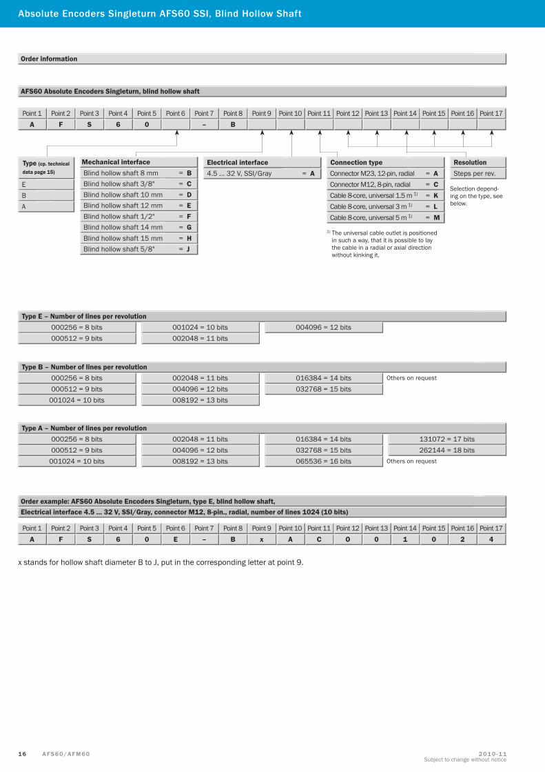
Order information
000256 = 8 bits Type E – Number of lines per revolution
Type B – Number of lines per revolution
AFS60 Absolute Encoders Singleturn, blind hollow shaft
Electrical interface 4.5 … 32 V, SSI/Gray, connector M12, 8-pin., radial, number of lines 1024 (10 bits)Order example: AFS60 Absolute Encoders Singleturn, type E, blind hollow shaft,
Type A – Number of lines per revolution
000512 = 9 bits001024 = 10 bits002048 = 11 bits
004096 = 12 bits
001024 = 10 bits
002048 = 11 bits004096 = 12 bits008192 = 13 bits
016384 = 14 bits032768 = 15 bits000512 = 9 bits
001024 = 10 bits
002048 = 11 bits004096 = 12 bits008192 = 13 bits
016384 = 14 bits032768 = 15 bits000512 = 9 bits065536 = 16 bits
131072 = 17 bits262144 = 18 bits
E
Type (cp. technical data page 15)
B
4.5 … 32 V, SSI/Gray = A Electrical interface Connection type
Connector M23, 12-pin, radial = A
Cable 8-core, universal 1.5 m 1) = K A
Connector M12, 8-pin, radial = C
Cable 8-core, universal 3 m 1) = L Cable 8-core, universal 5 m 1) = M
Point 1A
Point 2F
Point 3S
Point 46
Point 50
Point 6 Point 7–
Point 8B
Point 9 Point 10 Point 11 Point 12 Point 13 Point 14 Point 15 Point 16 Point 17
Point 1A
Point 2F
Point 3S
Point 46
Point 50
Point 6E
Point 7–
Point 8B
Point 9x
Point 10A
Point 11C
Point 12O
Point 130
Point 141
Point 150
Point 162
Point 174
000256 = 8 bits
000256 = 8 bits
1) The universal cable outlet is positioned in such a way, that it is possible to lay the cable in a radial or axial direction without kinking it.
Resolution
Selection depend-ing on the type, see below.
Steps per rev. Mechanical interface Blind hollow shaft 8 mm = B Blind hollow shaft 3/8" = C Blind hollow shaft 10 mm = D Blind hollow shaft 12 mm = E Blind hollow shaft 1/2" = F Blind hollow shaft 14 mm = G Blind hollow shaft 15 mm = H Blind hollow shaft 5/8" = J
x stands for hollow shaft diameter B to J, put in the corresponding letter at point 9.
Absolute Encoders Singleturn AFS60 SSI, Blind Hollow Shaft
Others on request
Others on request
1 7A F S 6 0 / A F M 6 02 0 1 0 - 1 1Subject to change without notice
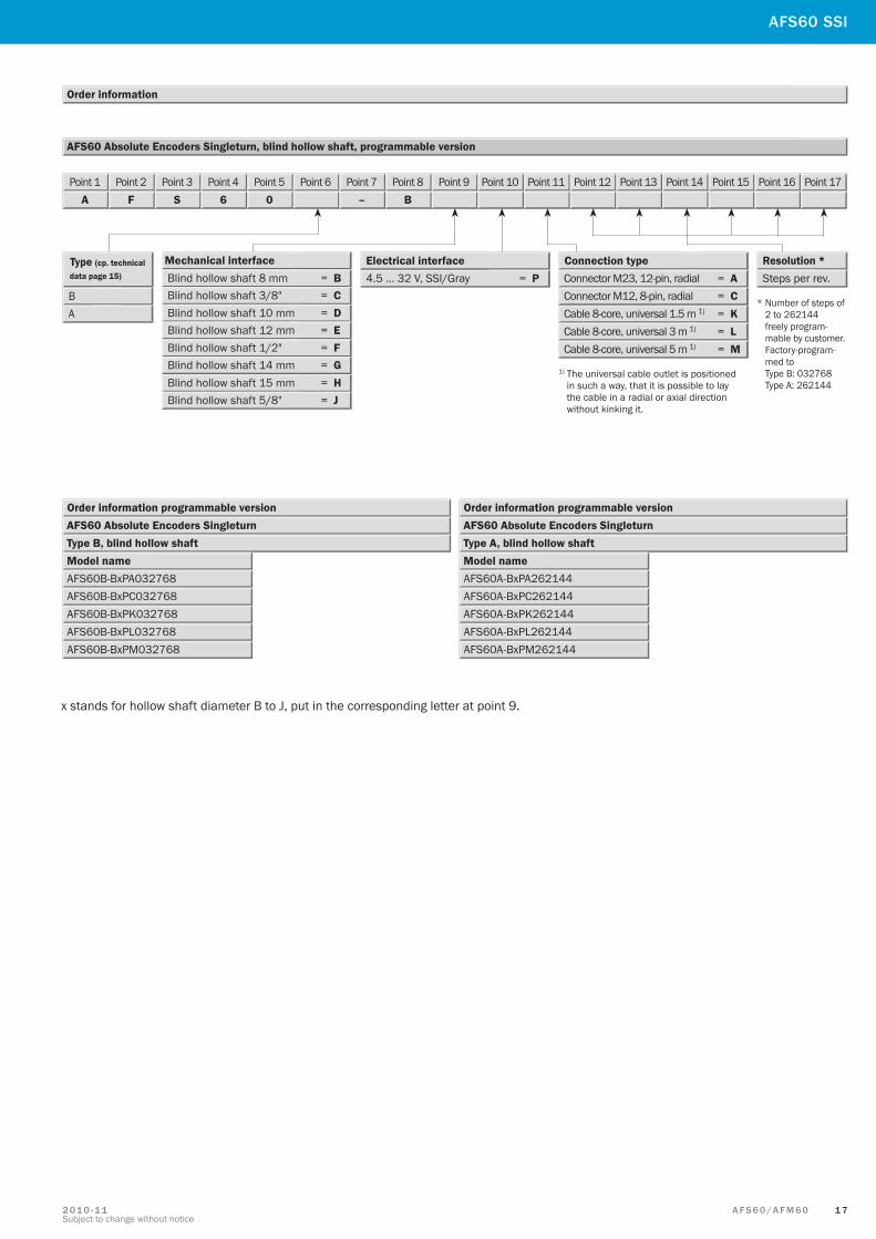
AFS60 Absolute Encoders Singleturn, blind hollow shaft, programmable version
Order information
Type (cp. technical data page 15)
B 4.5 … 32 V, SSI/Gray = P Electrical interface Connection type
Connector M23, 12-pin, radial = A
Cable 8-core, universal 1.5 m 1) = K A Connector M12, 8-pin, radial = C
Cable 8-core, universal 3 m 1) = L Cable 8-core, universal 5 m 1) = M
Point 1A
Point 2F
Point 3S
Point 46
Point 50
Point 6 Point 7–
Point 8B
Point 9 Point 10 Point 11 Point 12 Point 13 Point 14 Point 15 Point 16 Point 17
* Number of steps of 2 to 262144 freely program- mable by customer. Factory-program- med to Type B: 032768 Type A: 262144
1) The universal cable outlet is positioned in such a way, that it is possible to lay the cable in a radial or axial direction without kinking it.
Order information programmable versionAFS60 Absolute Encoders SingleturnType B, blind hollow shaftModel nameAFS60B-BxPA032768AFS60B-BxPC032768AFS60B-BxPK032768AFS60B-BxPL032768AFS60B-BxPM032768
Order information programmable versionAFS60 Absolute Encoders SingleturnType A, blind hollow shaftModel nameAFS60A-BxPA262144AFS60A-BxPC262144AFS60A-BxPK262144AFS60A-BxPL262144AFS60A-BxPM262144
Resolution * Steps per rev.
Mechanical interface Blind hollow shaft 8 mm = B Blind hollow shaft 3/8" = C Blind hollow shaft 10 mm = D Blind hollow shaft 12 mm = E Blind hollow shaft 1/2" = F Blind hollow shaft 14 mm = G Blind hollow shaft 15 mm = H Blind hollow shaft 5/8" = J
x stands for hollow shaft diameter B to J, put in the corresponding letter at point 9.
AFS60 SSI
1 8 A F S 6 0 / A F M 6 0 2 0 1 0 - 1 1Subject to change without notice
Mechanical interface Blind hollow shaft 8 mm = B Blind hollow shaft 3/8" = C Blind hollow shaft 10 mm = D Blind hollow shaft 12 mm = E Blind hollow shaft 1/2" = F Blind hollow shaft 14 mm = G Blind hollow shaft 15 mm = H
Mechanical interface Blind hollow shaft 8 mm = B Blind hollow shaft 3/8" = C Blind hollow shaft 10 mm = D Blind hollow shaft 12 mm = E Blind hollow shaft 1/2" = F Blind hollow shaft 14 mm = G Blind hollow shaft 15 mm = H
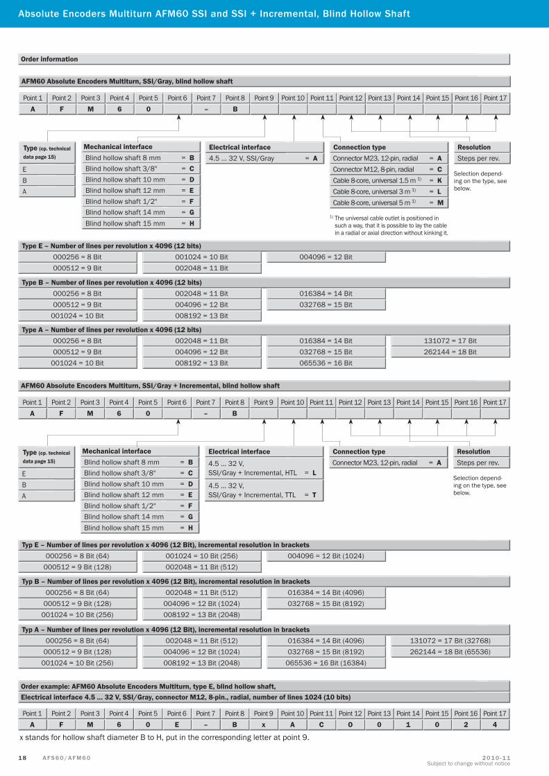
Absolute Encoders Multiturn AFM60 SSI and SSI + Incremental, Blind Hollow Shaft
Order information
AFM60 Absolute Encoders Multiturn, SSI/Gray, blind hollow shaft
Point 1A
Point 2F
Point 3M
Point 46
Point 50
Point 6 Point 7–
Point 8B
Point 9 Point 10 Point 11 Point 12 Point 13 Point 14 Point 15 Point 16 Point 17
E
Type (cp. technical data page 15)
B
4.5 … 32 V, SSI/Gray = A Electrical interface Connection type
Connector M23, 12-pin, radial = A
Cable 8-core, universal 1.5 m 1) = K A
Connector M12, 8-pin, radial = C
Cable 8-core, universal 3 m 1) = L Cable 8-core, universal 5 m 1) = M
1) The universal cable outlet is positioned in such a way, that it is possible to lay the cable in a radial or axial direction without kinking it.
Resolution
Selection depend-ing on the type, see below.
Steps per rev.
000256 = 8 Bit Type E – Number of lines per revolution x 4096 (12 bits)
000512 = 9 Bit001024 = 10 Bit002048 = 11 Bit
004096 = 12 Bit
Type B – Number of lines per revolution x 4096 (12 bits)
001024 = 10 Bit
002048 = 11 Bit004096 = 12 Bit008192 = 13 Bit
016384 = 14 Bit032768 = 15 Bit000512 = 9 Bit
000256 = 8 Bit
Type A – Number of lines per revolution x 4096 (12 bits)
001024 = 10 Bit
002048 = 11 Bit004096 = 12 Bit008192 = 13 Bit
016384 = 14 Bit032768 = 15 Bit000512 = 9 Bit065536 = 16 Bit
131072 = 17 Bit262144 = 18 Bit
000256 = 8 Bit
Electrical interface 4.5 … 32 V, SSI/Gray, connector M12, 8-pin., radial, number of lines 1024 (10 bits)Order example: AFM60 Absolute Encoders Multiturn, type E, blind hollow shaft,
Point 1A
Point 2F
Point 3M
Point 46
Point 50
Point 6E
Point 7–
Point 8B
Point 9x
Point 10A
Point 11C
Point 12O
Point 130
Point 141
Point 150
Point 162
Point 174
AFM60 Absolute Encoders Multiturn, SSI/Gray + Incremental, blind hollow shaft
000256 = 8 Bit (64) Typ E – Number of lines per revolution x 4096 (12 Bit), incremental resolution in brackets
000512 = 9 Bit (128)001024 = 10 Bit (256)002048 = 11 Bit (512)
004096 = 12 Bit (1024)
Typ B – Number of lines per revolution x 4096 (12 Bit), incremental resolution in brackets
001024 = 10 Bit (256)
002048 = 11 Bit (512)004096 = 12 Bit (1024)008192 = 13 Bit (2048)
016384 = 14 Bit (4096)032768 = 15 Bit (8192)000512 = 9 Bit (128)
000256 = 8 Bit (64)
Typ A – Number of lines per revolution x 4096 (12 Bit), incremental resolution in brackets
001024 = 10 Bit (256)
002048 = 11 Bit (512)004096 = 12 Bit (1024)008192 = 13 Bit (2048)
016384 = 14 Bit (4096)032768 = 15 Bit (8192)000512 = 9 Bit (128)
065536 = 16 Bit (16384)
131072 = 17 Bit (32768)262144 = 18 Bit (65536)
000256 = 8 Bit (64)
Point 1A
Point 2F
Point 3M
Point 46
Point 50
Point 6 Point 7–
Point 8B
Point 9 Point 10 Point 11 Point 12 Point 13 Point 14 Point 15 Point 16 Point 17
E
Type (cp. technical data page 15)
B
Electrical interface
4.5 … 32 V, SSI/Gray + Incremental, HTL = L
Connection type Connector M23, 12-pin, radial = A
A
Selection depend-ing on the type, see below.
Resolution Steps per rev.
4.5 … 32 V, SSI/Gray + Incremental, TTL = T
x stands for hollow shaft diameter B to H, put in the corresponding letter at point 9.
1 9A F S 6 0 / A F M 6 02 0 1 0 - 1 1Subject to change without notice
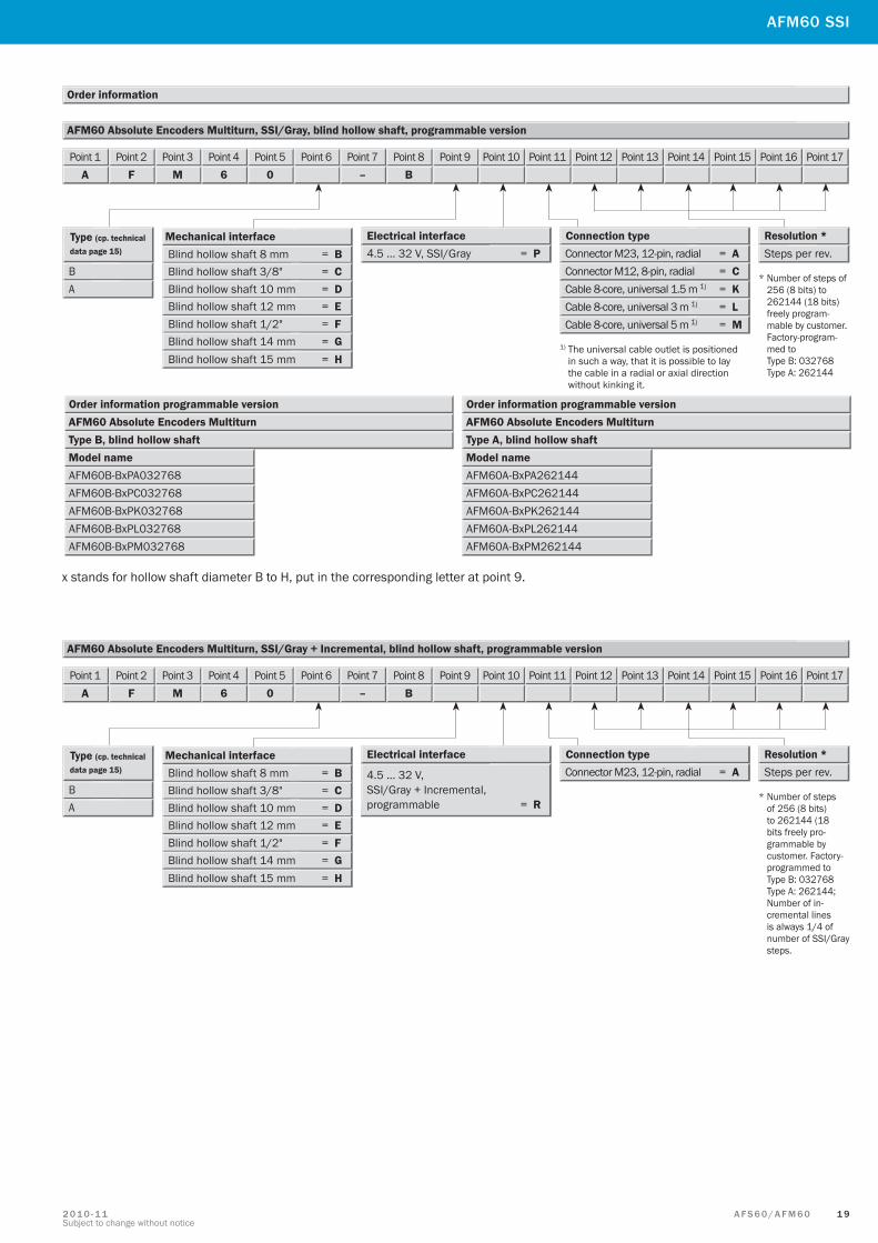
Order information programmable versionAFM60 Absolute Encoders MultiturnType B, blind hollow shaftModel nameAFM60B-BxPA032768AFM60B-BxPC032768AFM60B-BxPK032768AFM60B-BxPL032768AFM60B-BxPM032768
Order information programmable versionAFM60 Absolute Encoders MultiturnType A, blind hollow shaftModel nameAFM60A-BxPA262144AFM60A-BxPC262144AFM60A-BxPK262144AFM60A-BxPL262144AFM60A-BxPM262144
Mechanical interface Blind hollow shaft 8 mm = B Blind hollow shaft 3/8" = C Blind hollow shaft 10 mm = D Blind hollow shaft 12 mm = E Blind hollow shaft 1/2" = F Blind hollow shaft 14 mm = G Blind hollow shaft 15 mm = H
Mechanical interface Blind hollow shaft 8 mm = B Blind hollow shaft 3/8" = C Blind hollow shaft 10 mm = D Blind hollow shaft 12 mm = E Blind hollow shaft 1/2" = F Blind hollow shaft 14 mm = G Blind hollow shaft 15 mm = H
x stands for hollow shaft diameter B to H, put in the corresponding letter at point 9.
AFM60 SSI
Order information
AFM60 Absolute Encoders Multiturn, SSI/Gray, blind hollow shaft, programmable version
Point 1A
Point 2F
Point 3M
Point 46
Point 50
Point 6 Point 7–
Point 8B
Point 9 Point 10 Point 11 Point 12 Point 13 Point 14 Point 15 Point 16 Point 17
Type (cp. technical data page 15)
B 4.5 … 32 V, SSI/Gray = P Electrical interface Connection type
Connector M23, 12-pin, radial = A
Cable 8-core, universal 1.5 m 1) = K A Connector M12, 8-pin, radial = C
Cable 8-core, universal 3 m 1) = L Cable 8-core, universal 5 m 1) = M
1) The universal cable outlet is positioned in such a way, that it is possible to lay the cable in a radial or axial direction without kinking it.
* Number of steps of 256 (8 bits) to 262144 (18 bits) freely program- mable by customer. Factory-program- med to Type B: 032768 Type A: 262144
Resolution * Steps per rev.
4.5 … 32 V, SSI/Gray + Incremental, programmable = R
Point 1A
Point 2F
Point 3M
Point 46
Point 50
Point 6 Point 7–
Point 8B
Point 9 Point 10 Point 11 Point 12 Point 13 Point 14 Point 15 Point 16 Point 17
AFM60 Absolute Encoders Multiturn, SSI/Gray + Incremental, blind hollow shaft, programmable version
Type (cp. technical data page 15)
B
Electrical interface Connection type Connector M23, 12-pin, radial = A
A* Number of steps
of 256 (8 bits) to 262144 (18 bits freely pro-grammable by customer. Factory-programmed to Type B: 032768 Type A: 262144; Number of in-cremental lines is always 1/4 of number of SSI/Gray steps.
Resolution * Steps per rev.
2 0 A F S 6 0 / A F M 6 0 2 0 1 0 - 1 1Subject to change without notice
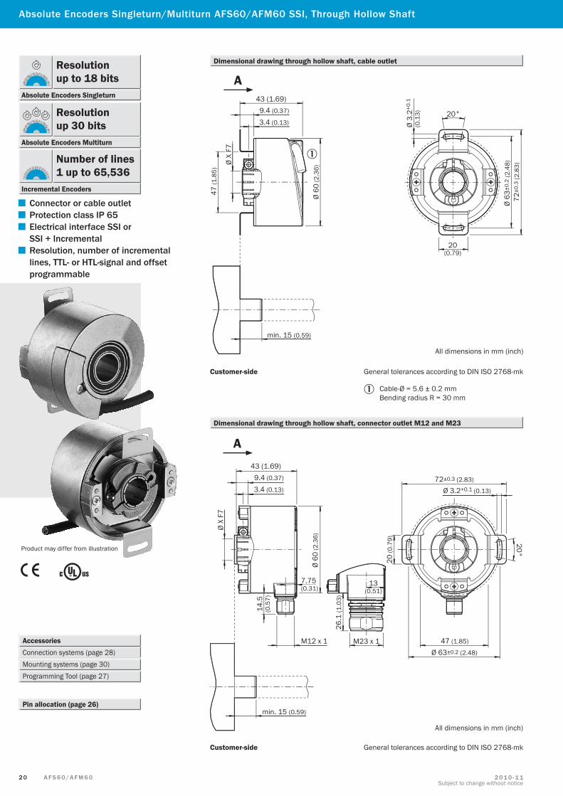
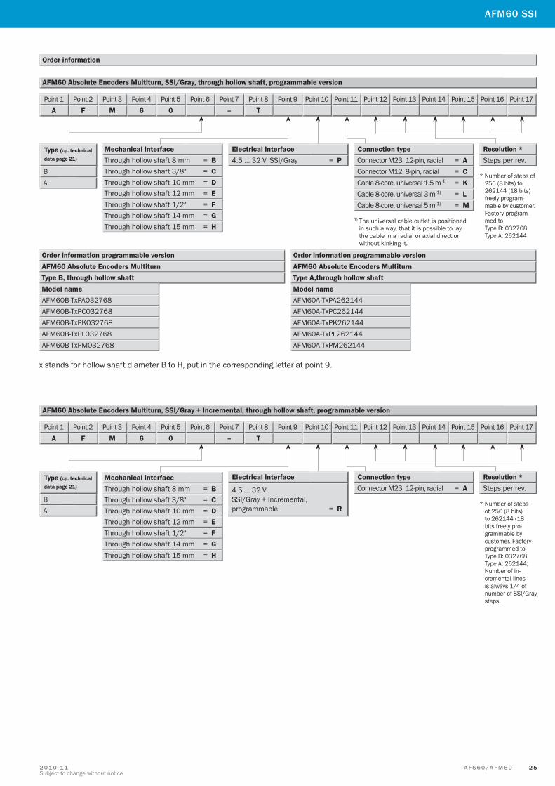
Absolute Encoders Singleturn/Multiturn AFS60/AFM60 SSI, Through Hollow Shaft
Accessories Connection systems (page 28) Mounting systems (page 30)Programming Tool (page 27)
Pin allocation (page 26)
Product may differ from illustration
Cable-Ø = 5.6 ± 0.2 mmBending radius R = 30 mm
Customer-side General tolerances according to DIN ISO 2768-mk
Dimensional drawing through hollow shaft, cable outlet
Dimensional drawing through hollow shaft, connector outlet M12 and M23
Customer-side General tolerances according to DIN ISO 2768-mk
All dimensions in mm (inch)
9.4 (0.37)
3.4 (0.13)
43 (1.69)
Ø X
F7
47 (1
.85)
min. 15 (0.59)
Ø 3.
2+0.
1
(0.1
3) 20°
20(0.79)
Ø 63
±0.2
(2.4
8)72
±0.3
(2.8
3)
Ø 60
(2.3
6)
A
9.4 (0.37)
3.4 (0.13)
43 (1.69)
Ø X
F7
min. 15 (0.59)
Ø 60
(2.3
6)
7.75(0.31)
14.5
(0.5
7)
M12 x 1
26.1
(1.0
3)
13(0.51)
M23 x 1
72±0.3 (2.83)
Ø 3.2+0.1 (0.13)
20°
20 (0
.79)
47 (1.85)
Ø 63±0.2 (2.48)
All dimensions in mm (inch)
A
▀ Connector or cable outlet
▀ Protection class IP 65
▀ Electrical interface SSI or SSI + Incremental
▀ Resolution, number of incremental lines, TTL- or HTL-signal and offset programmable
Resolution up to 18 bits
Absolute Encoders Singleturn
Resolution up 30 bits
Absolute Encoders Multiturn
Number of lines1 up to 65,536
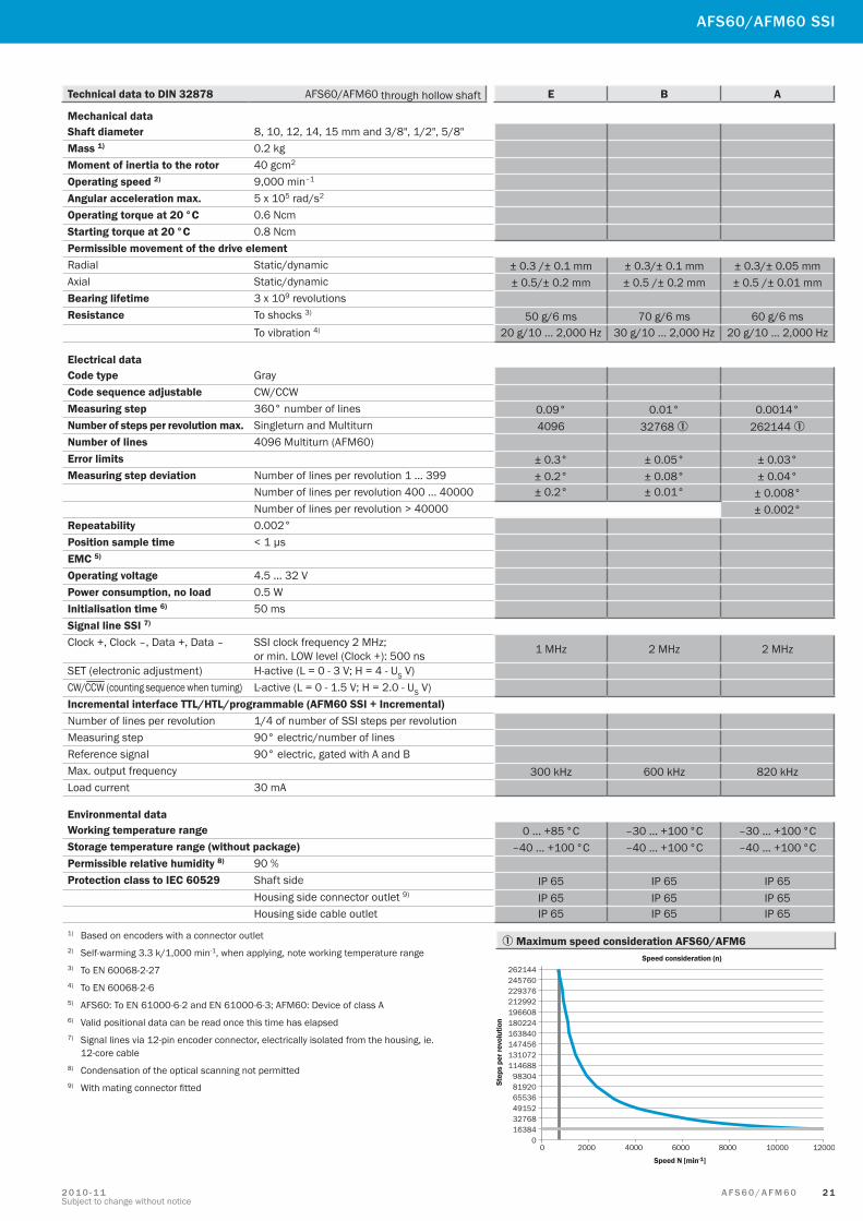
Incremental Encoders
2 1A F S 6 0 / A F M 6 02 0 1 0 - 1 1Subject to change without notice
AFS60/AFM60 SSI
Technical data to DIN 32878 AFS60/AFM60 through hollow shaft E B A
Mechanical dataShaft diameter 8, 10, 12, 14, 15 mm and 3/8", 1/2", 5/8"Mass 1) 0.2 kgMoment of inertia to the rotor 40 gcm2
Operating speed 2) 9,000 min–1
Angular acceleration max. 5 x 10⁵ rad/s2
Operating torque at 20 °C 0.6 NcmStarting torque at 20 °C 0.8 NcmPermissible movement of the drive elementRadial Static/dynamic ± 0.3 /± 0.1 mm ± 0.3/± 0.1 mm ± 0.3/± 0.05 mmAxial Static/dynamic ± 0.5/± 0.2 mm ± 0.5 /± 0.2 mm ± 0.5 /± 0.01 mmBearing lifetime 3 x 10⁹ revolutionsResistance To shocks 3) 50 g/6 ms 70 g/6 ms 60 g/6 ms
To vibration 4) 20 g/10 ... 2,000 Hz 30 g/10 ... 2,000 Hz 20 g/10 ... 2,000 Hz
Electrical dataCode type GrayCode sequence adjustable CW/CCWMeasuring step 360° number of lines 0.09° 0.01° 0.0014°Number of steps per revolution max. Singleturn and Multiturn 4096 32768 1 262144 1Number of lines 4096 Multiturn (AFM60)Error limits ± 0.3° ± 0.05° ± 0.03°Measuring step deviation Number of lines per revolution 1 … 399 ± 0.2° ± 0.08° ± 0.04°
Number of lines per revolution 400 … 40000 ± 0.2° ± 0.01° ± 0.008°Number of lines per revolution > 40000 ± 0.002°
Repeatability 0.002°Position sample time < 1 µsEMC 5)
Operating voltage 4.5 … 32 VPower consumption, no load 0.5 WInitialisation time 6) 50 msSignal line SSI 7) Clock +, Clock –, Data +, Data – SSI clock frequency 2 MHz;
or min. LOW level (Clock +): 500 ns 1 MHz 2 MHz 2 MHz
SET (electronic adjustment) H-active (L = 0 - 3 V; H = 4 - US V)CW/ CCW (counting sequence when turning) L-active (L = 0 - 1.5 V; H = 2.0 - US V)Incremental interface TTL/HTL/programmable (AFM60 SSI + Incremental)Number of lines per revolution 1/4 of number of SSI steps per revolutionMeasuring step 90° electric/number of linesReference signal 90° electric, gated with A and BMax. output frequency 300 kHz 600 kHz 820 kHzLoad current 30 mA
Environmental dataWorking temperature range 0 ... +85 °C –30 ... +100 °C –30 ... +100 °CStorage temperature range (without package) –40 ... +100 °C –40 ... +100 °C –40 ... +100 °CPermissible relative humidity 8) 90 %Protection class to IEC 60529 Shaft side IP 65 IP 65 IP 65
Housing side connector outlet 9) IP 65 IP 65 IP 65Housing side cable outlet IP 65 IP 65 IP 65
1) Based on encoders with a connector outlet2) Self-warming 3.3 k/1,000 min-1, when applying, note working temperature range3) To EN 60068-2-274) To EN 60068-2-65) AFS60: To EN 61000-6-2 and EN 61000-6-3; AFM60: Device of class A6) Valid positional data can be read once this time has elapsed7) Signal lines via 12-pin encoder connector, electrically isolated from the housing, ie.
12-core cable8) Condensation of the optical scanning not permitted9) With mating connector fitted
1 Maximum speed consideration AFS60/AFM6

2 2 A F S 6 0 / A F M 6 0 2 0 1 0 - 1 1Subject to change without notice
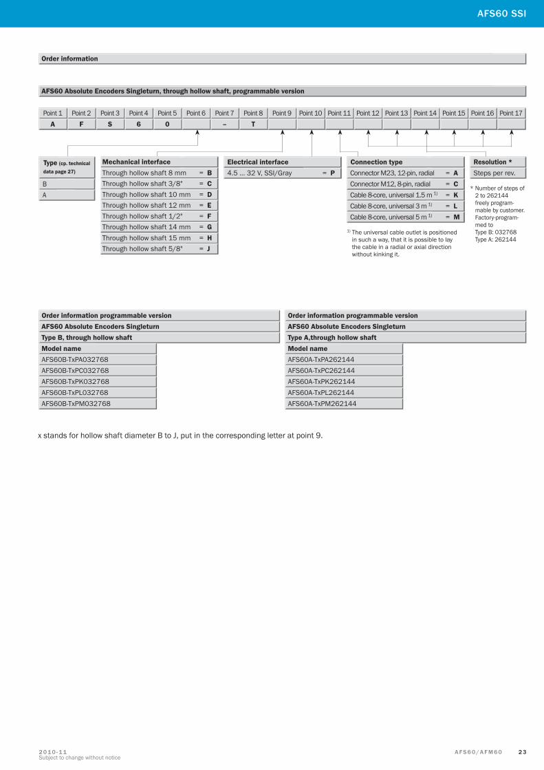
000256 = 8 bits Type E – Number of lines per revolution
Type B – Number of lines per revolution
AFS60 Absolute Encoders Singleturn, through hollow shaft
Electrical interface 4.5 … 32 V, SSI/Gray, connector M12, 8-pin., radial, number of lines 1024 (10 bits)Order example: AFS60 Absolute Encoders Singleturn, type E, through hollow shaft,
Type A – Number of lines per revolution
000512 = 9 bits001024 = 10 bits002048 = 11 bits
004096 = 12 bits
001024 = 10 bits
002048 = 11 bits004096 = 12 bits008192 = 13 bits
016384 = 14 bits032768 = 15 bits000512 = 9 bits
001024 = 10 bits
002048 = 11 bits004096 = 12 bits008192 = 13 bits
016384 = 14 bits032768 = 15 bits000512 = 9 bits065536 = 16 bits
131072 = 17 bits262144 = 18 bits
E
Type (cp. technical data page 27)
B
4.5 … 32 V, SSI/Gray = A Electrical interface Connection type
Connector M23, 12-pin, radial = A
Cable 8-core, universal 1.5 m 1) = K A
Connector M12, 8-pin, radial = C
Cable 8-core, universal 3 m 1) = L Cable 8-core, universal 5 m 1) = M
Point 1A
Point 2F
Point 3S
Point 46
Point 50
Point 6 Point 7–
Point 8T
Point 9 Point 10 Point 11 Point 12 Point 13 Point 14 Point 15 Point 16 Point 17
Point 1A
Point 2F
Point 3S
Point 46
Point 50
Point 6E
Point 7–
Point 8T
Point 9x
Point 10A
Point 11C
Point 12O
Point 130
Point 141
Point 150
Point 162
Point 174
000256 = 8 bits
000256 = 8 bits
1) The universal cable outlet is positioned in such a way, that it is possible to lay the cable in a radial or axial direction without kinking it.
Resolution
Selection depend-ing on the type, see below.
Steps per rev. Mechanical interface Through hollow shaft 8 mm = B Through hollow shaft 3/8" = C Through hollow shaft 10 mm = D Through hollow shaft 12 mm = E Through hollow shaft 1/2" = F Through hollow shaft 14 mm = G Through hollow shaft 15 mm = H Through hollow shaft 5/8" = J
x stands for hollow shaft diameter B to J, put in the corresponding letter at point 9.
Absolute Encoders Singleturn AFS60 SSI, Through Hollow Shaft
Order information
Others on request
Others on request
2 3A F S 6 0 / A F M 6 02 0 1 0 - 1 1Subject to change without notice
AFS60 Absolute Encoders Singleturn, through hollow shaft, programmable version
Order information
Type (cp. technical data page 27)
B 4.5 … 32 V, SSI/Gray = P Electrical interface Connection type
Connector M23, 12-pin, radial = A
Cable 8-core, universal 1.5 m 1) = K A Connector M12, 8-pin, radial = C
Cable 8-core, universal 3 m 1) = L Cable 8-core, universal 5 m 1) = M
Point 1A
Point 2F
Point 3S
Point 46
Point 50
Point 6 Point 7–
Point 8T
Point 9 Point 10 Point 11 Point 12 Point 13 Point 14 Point 15 Point 16 Point 17
* Number of steps of 2 to 262144 freely program- mable by customer. Factory-program- med to Type B: 032768 Type A: 262144
1) The universal cable outlet is positioned in such a way, that it is possible to lay the cable in a radial or axial direction without kinking it.
Order information programmable versionAFS60 Absolute Encoders SingleturnType B, through hollow shaftModel nameAFS60B-TxPA032768AFS60B-TxPC032768AFS60B-TxPK032768AFS60B-TxPL032768AFS60B-TxPM032768
Order information programmable versionAFS60 Absolute Encoders SingleturnType A,through hollow shaftModel nameAFS60A-TxPA262144AFS60A-TxPC262144AFS60A-TxPK262144AFS60A-TxPL262144AFS60A-TxPM262144
Resolution * Steps per rev.
Mechanical interface Through hollow shaft 8 mm = B Through hollow shaft 3/8" = C Through hollow shaft 10 mm = D Through hollow shaft 12 mm = E Through hollow shaft 1/2" = F Through hollow shaft 14 mm = G Through hollow shaft 15 mm = H Through hollow shaft 5/8" = J
x stands for hollow shaft diameter B to J, put in the corresponding letter at point 9.
AFS60 SSI
2 4 A F S 6 0 / A F M 6 0 2 0 1 0 - 1 1Subject to change without notice
Mechanical interface Through hollow shaft 8 mm = B Through hollow shaft 3/8" = C Through hollow shaft 10 mm = D Through hollow shaft 12 mm = E Through hollow shaft 1/2" = F Through hollow shaft 14 mm = G Through hollow shaft 15 mm = H
Mechanical interface Through hollow shaft 8 mm = B Through hollow shaft 3/8" = C Through hollow shaft 10 mm = D Through hollow shaft 12 mm = E Through hollow shaft 1/2" = F Through hollow shaft 14 mm = G Through hollow shaft 15 mm = H
Absolute Encoders Multiturn AFM60 SSI and SSI + Incremental, Through Hollow Shaft
Order information
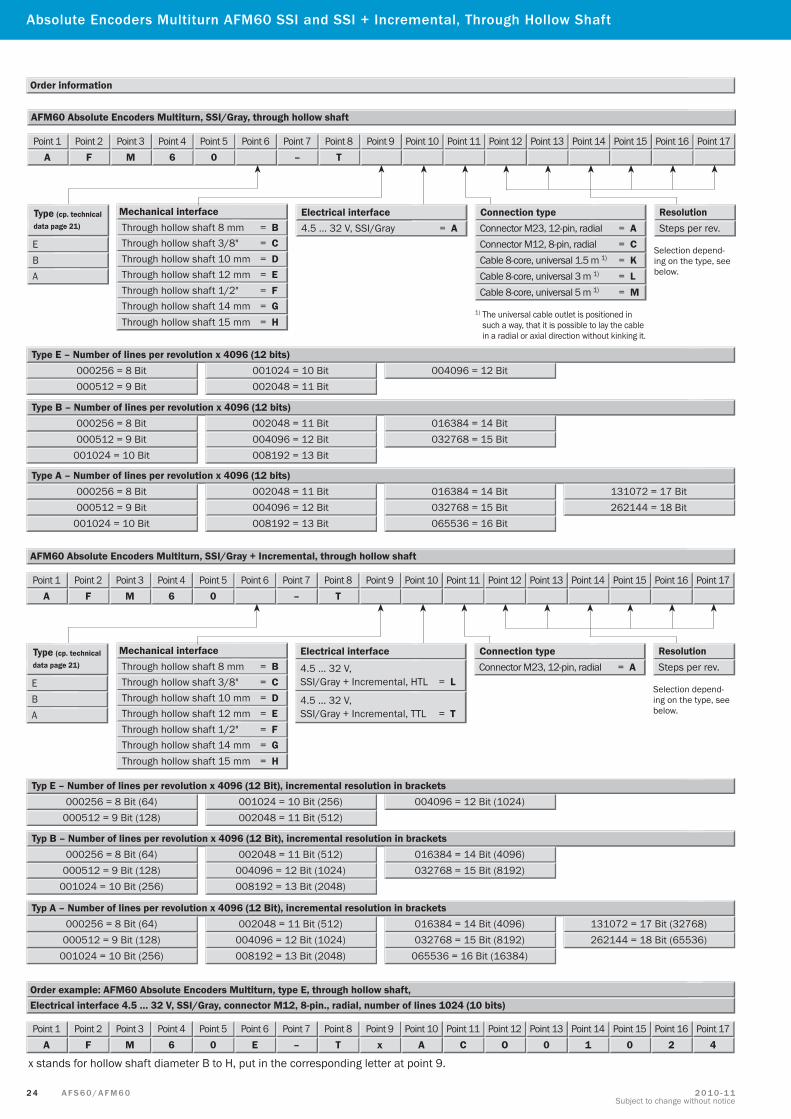
AFM60 Absolute Encoders Multiturn, SSI/Gray, through hollow shaft
Point 1A
Point 2F
Point 3M
Point 46
Point 50
Point 6 Point 7–
Point 8T
Point 9 Point 10 Point 11 Point 12 Point 13 Point 14 Point 15 Point 16 Point 17
E
Type (cp. technical data page 21)
B
4.5 … 32 V, SSI/Gray = A Electrical interface Connection type
Connector M23, 12-pin, radial = A
Cable 8-core, universal 1.5 m 1) = K A
Connector M12, 8-pin, radial = C
Cable 8-core, universal 3 m 1) = L Cable 8-core, universal 5 m 1) = M
1) The universal cable outlet is positioned in such a way, that it is possible to lay the cable in a radial or axial direction without kinking it.
Resolution
Selection depend-ing on the type, see below.
Steps per rev.
000256 = 8 Bit Type E – Number of lines per revolution x 4096 (12 bits)
000512 = 9 Bit001024 = 10 Bit002048 = 11 Bit
004096 = 12 Bit
Type B – Number of lines per revolution x 4096 (12 bits)
001024 = 10 Bit
002048 = 11 Bit004096 = 12 Bit008192 = 13 Bit
016384 = 14 Bit032768 = 15 Bit000512 = 9 Bit
000256 = 8 Bit
Type A – Number of lines per revolution x 4096 (12 bits)
001024 = 10 Bit
002048 = 11 Bit004096 = 12 Bit008192 = 13 Bit
016384 = 14 Bit032768 = 15 Bit000512 = 9 Bit065536 = 16 Bit
131072 = 17 Bit262144 = 18 Bit
000256 = 8 Bit
Electrical interface 4.5 … 32 V, SSI/Gray, connector M12, 8-pin., radial, number of lines 1024 (10 bits)Order example: AFM60 Absolute Encoders Multiturn, type E, through hollow shaft,
Point 1A
Point 2F
Point 3M
Point 46
Point 50
Point 6E
Point 7–
Point 8T
Point 9x
Point 10A
Point 11C
Point 12O
Point 130
Point 141
Point 150
Point 162
Point 174
AFM60 Absolute Encoders Multiturn, SSI/Gray + Incremental, through hollow shaft
000256 = 8 Bit (64) Typ E – Number of lines per revolution x 4096 (12 Bit), incremental resolution in brackets
000512 = 9 Bit (128)001024 = 10 Bit (256)002048 = 11 Bit (512)
004096 = 12 Bit (1024)
Typ B – Number of lines per revolution x 4096 (12 Bit), incremental resolution in brackets
001024 = 10 Bit (256)
002048 = 11 Bit (512)004096 = 12 Bit (1024)008192 = 13 Bit (2048)
016384 = 14 Bit (4096)032768 = 15 Bit (8192)000512 = 9 Bit (128)
000256 = 8 Bit (64)
Typ A – Number of lines per revolution x 4096 (12 Bit), incremental resolution in brackets
001024 = 10 Bit (256)
002048 = 11 Bit (512)004096 = 12 Bit (1024)008192 = 13 Bit (2048)
016384 = 14 Bit (4096)032768 = 15 Bit (8192)000512 = 9 Bit (128)
065536 = 16 Bit (16384)
131072 = 17 Bit (32768)262144 = 18 Bit (65536)
000256 = 8 Bit (64)
Point 1A
Point 2F
Point 3M
Point 46
Point 50
Point 6 Point 7–
Point 8T
Point 9 Point 10 Point 11 Point 12 Point 13 Point 14 Point 15 Point 16 Point 17
E
Type (cp. technical data page 21)
B
Electrical interface
4.5 … 32 V, SSI/Gray + Incremental, HTL = L
Connection type Connector M23, 12-pin, radial = A
A
Selection depend-ing on the type, see below.
Resolution Steps per rev.
4.5 … 32 V, SSI/Gray + Incremental, TTL = T
x stands for hollow shaft diameter B to H, put in the corresponding letter at point 9.
2 5A F S 6 0 / A F M 6 02 0 1 0 - 1 1Subject to change without notice
Order information programmable versionAFM60 Absolute Encoders MultiturnType B, through hollow shaftModel nameAFM60B-TxPA032768AFM60B-TxPC032768AFM60B-TxPK032768AFM60B-TxPL032768AFM60B-TxPM032768
Order information programmable versionAFM60 Absolute Encoders MultiturnType A,through hollow shaftModel nameAFM60A-TxPA262144AFM60A-TxPC262144AFM60A-TxPK262144AFM60A-TxPL262144AFM60A-TxPM262144
Mechanical interface Through hollow shaft 8 mm = B Through hollow shaft 3/8" = C Through hollow shaft 10 mm = D Through hollow shaft 12 mm = E Through hollow shaft 1/2" = F Through hollow shaft 14 mm = G Through hollow shaft 15 mm = H
Mechanical interface Through hollow shaft 8 mm = B Through hollow shaft 3/8" = C Through hollow shaft 10 mm = D Through hollow shaft 12 mm = E Through hollow shaft 1/2" = F Through hollow shaft 14 mm = G Through hollow shaft 15 mm = H
AFM60 SSI
x stands for hollow shaft diameter B to H, put in the corresponding letter at point 9.
Order information
AFM60 Absolute Encoders Multiturn, SSI/Gray, through hollow shaft, programmable version
Point 1A
Point 2F
Point 3M
Point 46
Point 50
Point 6 Point 7–
Point 8T
Point 9 Point 10 Point 11 Point 12 Point 13 Point 14 Point 15 Point 16 Point 17
Type (cp. technical data page 21)
B 4.5 … 32 V, SSI/Gray = P Electrical interface Connection type
Connector M23, 12-pin, radial = A
Cable 8-core, universal 1.5 m 1) = K A Connector M12, 8-pin, radial = C
Cable 8-core, universal 3 m 1) = L Cable 8-core, universal 5 m 1) = M
1) The universal cable outlet is positioned in such a way, that it is possible to lay the cable in a radial or axial direction without kinking it.
* Number of steps of 256 (8 bits) to 262144 (18 bits) freely program- mable by customer. Factory-program- med to Type B: 032768 Type A: 262144
Resolution * Steps per rev.
4.5 … 32 V, SSI/Gray + Incremental, programmable = R
Point 1A
Point 2F
Point 3M
Point 46
Point 50
Point 6 Point 7–
Point 8T
Point 9 Point 10 Point 11 Point 12 Point 13 Point 14 Point 15 Point 16 Point 17
AFM60 Absolute Encoders Multiturn, SSI/Gray + Incremental, through hollow shaft, programmable version
Type (cp. technical data page 21)
B
Electrical interface Connection type Connector M23, 12-pin, radial = A
A* Number of steps
of 256 (8 bits) to 262144 (18 bits freely pro-grammable by customer. Factory-programmed to Type B: 032768 Type A: 262144; Number of in-cremental lines is always 1/4 of number of SSI/Gray steps.
Resolution * Steps per rev.
2 6 A F S 6 0 / A F M 6 0 2 0 1 0 - 1 1Subject to change without notice
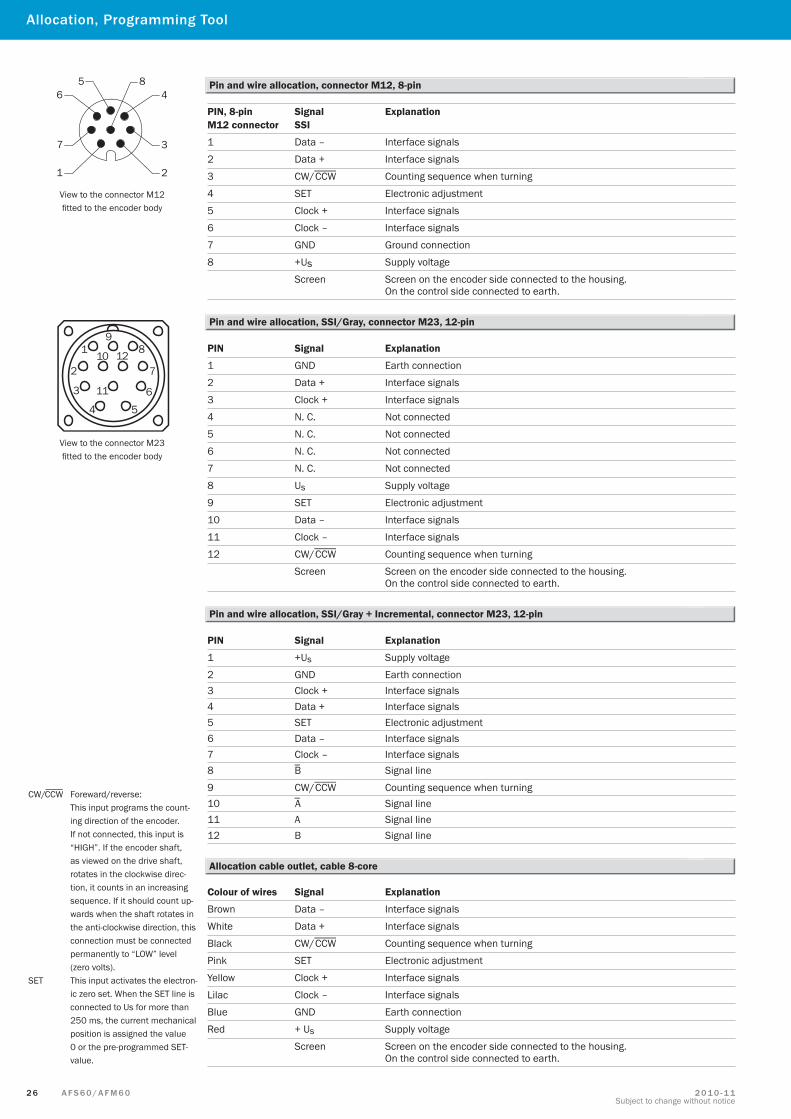
PIN, 8-pin Signal ExplanationM12 connector SSI
1 Data – Interface signals
2 Data + Interface signals
3 CW/CCW Counting sequence when turning
4 SET Electronic adjustment
5 Clock + Interface signals
6 Clock – Interface signals
7 GND Ground connection
8 +Us Supply voltage
Screen Screen on the encoder side connected to the housing. On the control side connected to earth.
View to the connector M12 fitted to the encoder body
Pin and wire allocation, connector M12, 8-pin
CW/CCW Foreward/reverse: This input programs the count-ing direction of the encoder. If not connected, this input is “HIGH”. If the encoder shaft, as viewed on the drive shaft, rotates in the clockwise direc-tion, it counts in an increasing sequence. If it should count up-wards when the shaft rotates in the anti-clockwise direction, this connection must be connected permanently to “LOW” level (zero volts).
SET This input activates the electron-ic zero set. When the SET line is connected to Us for more than 250 ms, the current mechanical position is assigned the value 0 or the pre-programmed SET-value.
Colour of wires Signal Explanation
Brown Data – Interface signals
White Data + Interface signals
Black CW/CCW Counting sequence when turning
Pink SET Electronic adjustment
Yellow Clock + Interface signals
Lilac Clock – Interface signals
Blue GND Earth connection
Red + Us Supply voltage
Screen Screen on the encoder side connected to the housing. On the control side connected to earth.
Allocation cable outlet, cable 8-core
PIN Signal Explanation
1 GND Earth connection
2 Data + Interface signals
3 Clock + Interface signals
4 N. C. Not connected
5 N. C. Not connected
6 N. C. Not connected
7 N. C. Not connected
8 Us Supply voltage
9 SET Electronic adjustment
10 Data – Interface signals
11 Clock – Interface signals
12 CW/CCW Counting sequence when turning
Screen Screen on the encoder side connected to the housing. On the control side connected to earth.
View to the connector M23 fitted to the encoder body
Pin and wire allocation, SSI/Gray, connector M23, 12-pin
Allocation, Programming Tool
PIN Signal Explanation
1 +Us Supply voltage
2 GND Earth connection 3 Clock + Interface signals4 Data + Interface signals5 SET Electronic adjustment6 Data – Interface signals7 Clock – Interface signals8 B Signal line
9 CW/CCW Counting sequence when turning10 A Signal line 11 A Signal line12 B Signal line
Pin and wire allocation, SSI/Gray + Incremental, connector M23, 12-pin
2 7A F S 6 0 / A F M 6 02 0 1 0 - 1 1Subject to change without notice
AFS60/AFM60 SSI
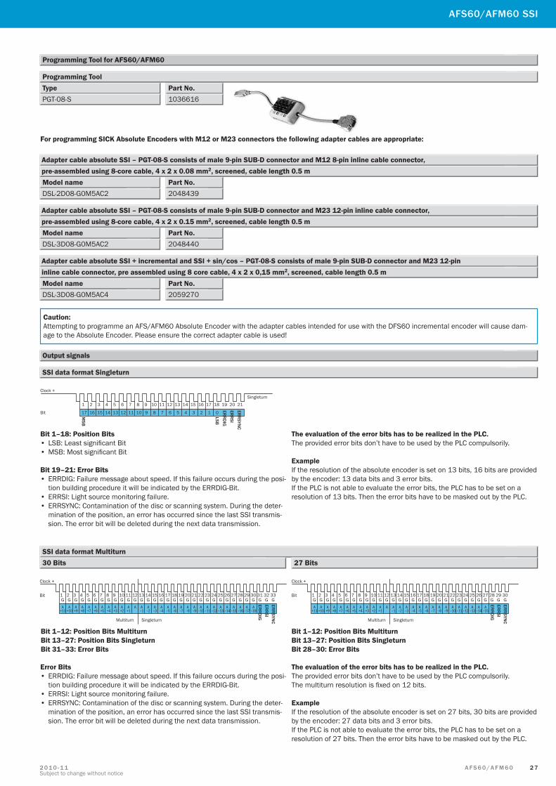
TypePGT-08-S 1036616
Part No.
For programming SICK Absolute Encoders with M12 or M23 connectors the following adapter cables are appropriate:
DSL-2D08-G0M5AC2Model name
2048439Part No.
Adapter cable absolute SSI – PGT-08-S consists of male 9-pin SUB-D connector and M12 8-pin inline cable connector, pre-assembled using 8-core cable, 4 x 2 x 0.08 mm2, screened, cable length 0.5 m
DSL-3D08-G0M5AC2Model name
2048440Part No.
Adapter cable absolute SSI – PGT-08-S consists of male 9-pin SUB-D connector and M23 12-pin inline cable connector, pre-assembled using 8-core cable, 4 x 2 x 0.15 mm2, screened, cable length 0.5 m
DSL-3D08-G0M5AC4Model name
2059270Part No.
Adapter cable absolute SSI + incremental and SSI + sin/cos – PGT-08-S consists of male 9-pin SUB-D connector and M23 12-pin inline cable connector, pre assembled using 8 core cable, 4 x 2 x 0,15 mm2, screened, cable length 0.5 m
Programming Tool
SSI data format Singleturn
Caution: Attempting to programme an AFS/AFM60 Absolute Encoder with the adapter cables intended for use with the DFS60 incremental encoder will cause dam-age to the Absolute Encoder. Please ensure the correct adapter cable is used!
Programming Tool for AFS60/AFM60
Output signals
Clock +
Bit
Singleturn
1 2 3 4 5 6 7 8 9 10 11 12 13 14 15 16 17 18 19 20 21
17 16 15 14 13 12 11 10 9 8 7 6 5 4 3 2 1 0MSB
LSBER
RD
IGER
RSI
ERR
SYNC
Bit 1–18: Position Bits• LSB: Least significant Bit• MSB: Most significant Bit
Bit 19–21: Error Bits• ERRDIG: Failure message about speed. If this failure occurs during the posi-
tion building procedure it will be indicated by the ERRDIG-Bit.• ERRSI: Light source monitoring failure.• ERRSYNC: Contamination of the disc or scanning system. During the deter-
mination of the position, an error has occurred since the last SSI transmis-sion. The error bit will be deleted during the next data transmission.
The evaluation of the error bits has to be realized in the PLC.The provided error bits don’t have to be used by the PLC compulsorily.
ExampleIf the resolution of the absolute encoder is set on 13 bits, 16 bits are provided by the encoder: 13 data bits and 3 error bits. If the PLC is not able to evaluate the error bits, the PLC has to be set on a resolution of 13 bits. Then the error bits have to be masked out by the PLC.
SSI data format Multiturn
Clock +
Bit
SingleturnMultiturn
1G G G G G G G G G G G G G G G G G G G G G G G G G G G G G G G GG
2 3 4 5 6 7 8 9 10 11 12 13 14 15 16 17 18 19 20 21 22 23 24 25 26 27 28 29 30 31 32 33
AA+1
A–1
A–2
A–3
A–4
A–5
A–6
A–7
A–8
A–9
A–10
A–11
A–12
A–13
A–14
A–15
A–16
A–17
A–18
A+2
A+3
A+4
A+5
A+6
A+7
A+8
A+9
A+10
A+11
ERR
DIG
ERR
SIER
RSYN
C
Clock +
Bit
SingleturnMultiturn
1G G G G G G G G G G G G G G G G G G G G G G G G G G G G G G
2 3 4 5 6 7 8 9 10 11 12 13 14 15 16 17 18 19 20 21 22 23 24 25 26 27 28 29 30
AA+1
A–1
A–2
A–3
A–4
A–5
A–6
A–7
A–8
A–9
A–10
A–11
A–12
A–13
A–14
A–15
A+2
A+3
A+4
A+5
A+6
A+7
A+8
A+9
A+10
A+11
ERR
DIG
ERR
SIER
RSYN
C
Error Bits• ERRDIG: Failure message about speed. If this failure occurs during the posi-
tion building procedure it will be indicated by the ERRDIG-Bit.• ERRSI: Light source monitoring failure.• ERRSYNC: Contamination of the disc or scanning system. During the deter-
mination of the position, an error has occurred since the last SSI transmis-sion. The error bit will be deleted during the next data transmission.
The evaluation of the error bits has to be realized in the PLC.The provided error bits don’t have to be used by the PLC compulsorily. The multiturn resolution is fixed on 12 bits.
ExampleIf the resolution of the absolute encoder is set on 27 bits, 30 bits are provided by the encoder: 27 data bits and 3 error bits. If the PLC is not able to evaluate the error bits, the PLC has to be set on a resolution of 27 bits. Then the error bits have to be masked out by the PLC.
30 Bits 27 Bits
Bit 1–12: Position Bits MultiturnBit 13–27: Position Bits SingleturnBit 31–33: Error Bits
Bit 1–12: Position Bits MultiturnBit 13–27: Position Bits SingleturnBit 28–30: Error Bits
2 8 A F S 6 0 / A F M 6 0 2 0 1 0 - 1 1Subject to change without notice
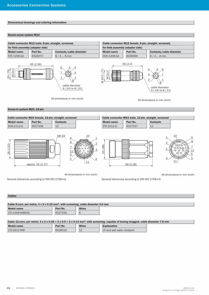
Screw-in system M23, 12-pin
All dimensions in mm (inch) All dimensions in mm (inch)
General tolerances according to DIN ISO 2768-mk General tolerances according to DIN ISO 2768-mk
Cable connector M23 female, 12-pin, straight, screened Cable connector M23 male, 12-pin, straight, screened
6027538Contacts Part No.12
Model nameDOS-2312-G
Part No.6027537
Contacts12
Model nameSTE-2312-G
Cables
Dimensional drawings and ordering information
Round screw system M12
Cable connector M12 male, 8-pin, straight, screened,
Part No.6028370
Model nameSTE-1208-GA
for field assembly (adapter side)Contacts/cable diameter8 / 4 … 8 mm
Cable connector M12 female, 8-pin, straight, screened,
Part No.6028369
Model nameDOS-1208-GA
for field assembly (adapter side)Contacts/cable diameter8 / 4 … 8 mm
All dmensions in mm (inch) All dimensions in mm (inch)
LTG-2308-MWENCModel name
8Wires
6027529Part No.
Cable 8-core, per metre, 4 x 2 x 0.15 mm2, with screening, cable diameter 5.6 mm
LTG-2612-MWModel name
12Wires
6028516Part No.
Cable 12-core, per metre, 4 x 2 x 0.25 + 2 x 0.5 + 2 x 0.14 mm2, with screening, capable of beeing dragged, cable diameter 7.8 mm
UV and salt water resistantExplanation
Accessories Connection Systems
2 9A F S 6 0 / A F M 6 02 0 1 0 - 1 1Subject to change without notice
Dimensional drawings and ordering information
6032866Contacts8
Part No. Female connector M12, 8-pin, straight, pre-wired with cable 8-wire, 4 x 2 x 0.25 mm2, screened, flexible (adapter side)
Cable length2.0 m
6032867 8 5.0 m6032868 8 10.0 m6032869 8 20.0 m
DOL-0J08-G0M5AA6Model name
0.5 mCable length
2048589Part No.
Cable connector female JST inc. sealing, 8-core, 4 x 2 x 0.15 mm2, with screening, cable diameter 5.6 mm
DOL-0J08-G1M5AA6 1.5 m2048590DOL-0J08-G03MAA6 3.0 m2048591DOL-0J08-G05MAA6 5.0 m2048593DOL-0J08-G10MAA6 10.0 m2048594
Female connectors
DOL-2308-G0M5AA6Model name
0.5 mCable length
2048595Part No.
Cable connector female M23, 8-core, 4 x 2 x 0.15 mm2, cable diameter 5.6 mm
DOL-2308-G1M5AA6 1.5 m2048596DOL-2308-G03MAA6 3.0 m2048597DOL-2308-G05MAA6 5.0 m2048598DOL-2308-G10MAA6 10.0 m2048599
All dimensions in mm (inch)
DOL-1208-G02MAC1Model name
DOL-1208-G05MAC1DOL-1208-G10MAC1DOL-1208-G20MAC1
AFS60/AFM60
3 0 A F S 6 0 / A F M 6 0 2 0 1 0 - 1 1Subject to change without notice
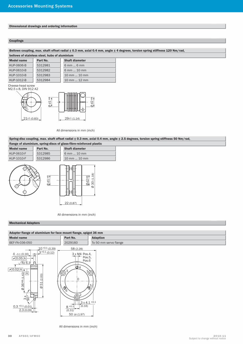
Couplings
Dimensional drawings and ordering information
Accessories Mounting Systems
Model name
Bellows coupling, max. shaft offset radial ± 0.3 mm, axial 0.4 mm, angle ± 4 degrees, torsion spring stiffness 120 Nm/rad,
Shaft diameterbellows of stainless steel, hubs of aluminium
KUP-0606-BKUP-0610-BKUP-1010-BKUP-1012-B
Part No.5312981531298253129835312984
6 mm … 6 mm6 mm … 10 mm10 mm … 10 mm10 mm … 12 mm
Cheese-head screwM2.5 x 8, DIN 912 A2
21±1 (0.83) 29±1 (1.14)
Ø d1
H8
Ø d2
H8
All dimensions in mm (inch)
Model name
Spring-disc coupling, max. shaft offset radial ± 0.3 mm, axial 0.4 mm, angle ± 2.5 degrees, torsion spring stiffness 50 Nm/rad,
Shaft diameterflange of aluminium, spring-discs of glass-fibre-reinforced plastic
KUP-0610-FKUP-1010-F
Part No.53129855312986
6 mm … 10 mm10 mm … 10 mm
Ø d2
H8
Ø d1
H8
22 (0.87)
Ø 30
(1.1
8)
All dimensions in mm (inch)
Mechanical Adapters
Adapter flange of aluminium for face mount flange, spigot 36 mmModel name Part No.
2029160BEF-FA-036-050AdaptionTo 50 mm servo flange
10 +0.1 (0.39) 3 +0.1 (0.12) 4 –0.1 (0.16)
Ø 51
(2.0
0)
Ø 36
H8
(1.4
2)
0.3 +0.1 (0.01)2.3 (0.09)
3 x
90°
58 (2.28)
3 x M4 Pos.4,Pos.5,Pos.6
41
0
5
26
3
50 18 (1.97)
3 x 4.1 +0.1
(0.16)8 +0.1
(0.31)
Rz 6.3
A0.02 A
0.05 A
All dimensions in mm (inch)
3 1A F S 6 0 / A F M 6 02 0 1 0 - 1 1Subject to change without notice
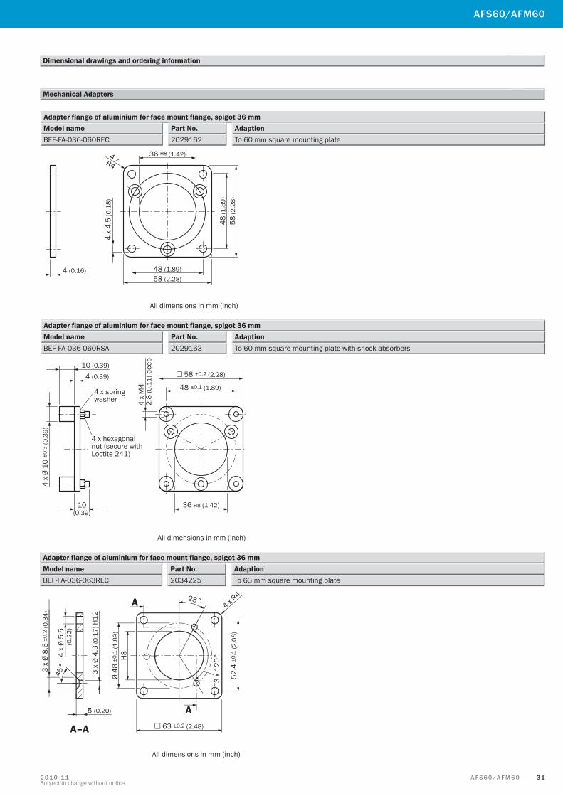
Dimensional drawings and ordering information
Mechanical Adapters
AFS60/AFM60
Adapter flange of aluminium for face mount flange, spigot 36 mmModel name Part No.
2029162BEF-FA-036-060RECAdaptionTo 60 mm square mounting plate
36 H8 (1.42)4 xR4
4 x
4.5
(0.1
8)
48 (1.89)58 (2.28)
48 (1
.89)
58 (2
.28)
4 (0.16)
All dimensions in mm (inch)
Adapter flange of aluminium for face mount flange, spigot 36 mmModel name Part No.
2029163BEF-FA-036-060RSAAdaptionTo 60 mm square mounting plate with shock absorbers
10 (0.39)
10(0.39)
4 (0.39)
4 x springwasher
4 x hexagonalnut (secure withLoctite 241)
4 x
Ø 10
±0.
3 (0
.39)
All dimensions in mm (inch)
4 x
M4
2.8
(0.1
1) d
eep
48 ±0.1 (1.89)
36 H8 (1.42)
58 ±0.2 (2.28)
Adapter flange of aluminium for face mount flange, spigot 36 mmModel name Part No.
2034225BEF-FA-036-063RECAdaptionTo 63 mm square mounting plate
A
A
A–A
28°4 x R
4
52.4
±0.
1 (2
.06)
3 x
120°
63 ±0.2 (2.48)
Ø 48
±0.
1 (1
.89)
H8
5 (0.20)
3 x
Ø 8.
6 ±0
.2 (0
.34)
45°
4 x
Ø 5.
5(0
.22)
3 x
Ø 4.
3 (0
.17)
H12
All dimensions in mm (inch)
3 2 A F S 6 0 / A F M 6 0 2 0 1 0 - 1 1Subject to change without notice
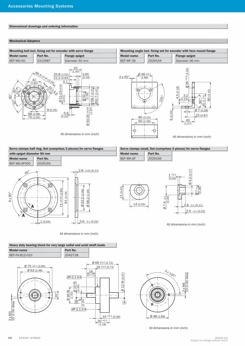
Dimensional drawings and ordering information
Mechanical Adapters
Accessories Mounting Systems
Mounting bell incl. fixing set for encoder with servo flangePart No.5312987
Model nameBEF-MG-50
Flange spigotDiameter 50 mm
Mounting angle incl. fixing set for encoder with face mount flangePart No.2029164
Model nameBEF-WF-36
Flange spigotDiameter 36 mm
85.5 ±0.05 (3.25)42
(1.65)10 x 4.5
(0.18)
9 (0.35)68 (2.68)75 (2.95)
90° 30
°30
°25
°
33(1.30)
3.95(0.16)
25.8 (1.02)21.2 (0.83)
0.1
Ø 62
.7 (2
.47)
Ø 58
.7 (2
.31)
Ø 50
.05
±0.0
3(1
.97)
Ø 32
.1(1
.26)
Ø 51
.03
±0.0
3(2
.01)
5.9(0.23)
All dimensions in mm (inch)
Ø 48 ±0.1(1.89)2 x 45°
120°
80 (3.15)60 (2.36)
80 (3
.15)
45 (1
.77)
90°
Ø 36
+0.5
(1.4
2)
3.2(0.13)4.
5 (0
.18)
6 (0
.24)
40(1.57)
22 (0.87)
Ø 7 (0.28)
All dimensions in mm (inch)
Servo clamps half ring, Set (comprises 2 pieces) for servo flanges
Part No.2029165
Model nameBEF-WG-SF050
with spigot diameter 50 mmServo clamps small, Set (comprises 3 pieces) for servo flanges
Part No.2029166
Model nameBEF-WK-SF
4 x
90°
A
A
45°
1 (0.04)
71 ±
0.02
(2.8
0)
81 (3
.19)
5.6 –0.1 (0.22)
2.8 –0.05 (0.11)
Ø 52
.2 (2
.06)
Ø 58
.2 (2
.29)
All dimensions in mm (inch)
11 (0
.43)
14 (0.55)
Ø 7.
4 –0
.1(0
.29)
1 +0.1
(0.04)
Ø 4.
2 (0
.17)
Ø 7–
0.1
(0.2
8)
2.8 –0.1 (0.11)
5.5 –0.1 (0.22)
All dimensions in mm (inch)
10 +0.1 (0.39)30 +0.1
(1.18)
A
3 x 120°
Ø 75 ±0.1 (2.95)Ø 63 (2.48)
20°
3 x
M3
10 (0
.39)
dee
p
0.1 A-B
Ø 69 ±0.2 (2.72)19 ±0.5 (0.75)
18(0.71)
B
0.1 A-B
Ø 36
f8(1
.42)
Ø 10
f6(0
.39)
9(0
.35)
Ø 12
f6 (0
.47)
3 x
M4
10 (0
.39)
dee
p
Ø 48 (1.89)
All dimensions in mm (inch)
BEF-FA-B12-010Model name
2042728Part No.
Heavy duty bearing block for very large radial and axial shaft loads
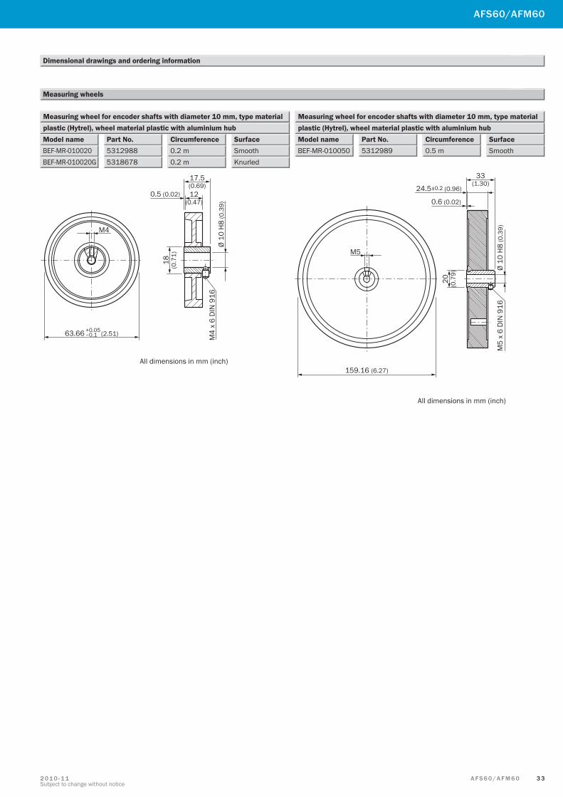
3 3A F S 6 0 / A F M 6 02 0 1 0 - 1 1Subject to change without notice
Dimensional drawings and ordering information
Measuring wheel for encoder shafts with diameter 10 mm, type material
Part No.5312988
Model nameBEF-MR-010020
plastic (Hytrel), wheel material plastic with aluminium hubCircumference0.2 m
SurfaceSmooth
5318678BEF-MR-010020G 0.2 m Knurled
Measuring wheel for encoder shafts with diameter 10 mm, type material
Part No.5312989
Model nameBEF-MR-010050
plastic (Hytrel), wheel material plastic with aluminium hubCircumference0.5 m
SurfaceSmooth
AFS60/AFM60
Measuring wheels
M4
All dimensions in mm (inch)
63.66 +0.05–0.1 (2.51)
17.5(0.69)12
(0.47)0.5 (0.02)
18 (0.7
1)
Ø 10
H8
(0.3
9)M
4 x
6 D
IN 9
16
M5
159.16 (6.27)
All dimensions in mm (inch)
33(1.30)
24.5±0.2 (0.96)
0.6 (0.02)
Ø 10
H8
(0.3
9)M
5 x
6 D
IN 9
16
20 (0.7
9)
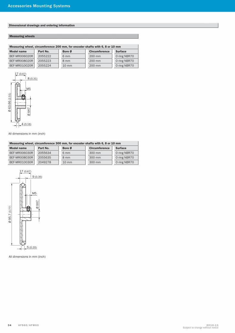
3 4 A F S 6 0 / A F M 6 0 2 0 1 0 - 1 1Subject to change without notice
Measuring wheels
Measuring wheel, circumference 200 mm, for encoder shafts with 6, 8 or 10 mmModel name Part No. Bore Ø Circumference SurfaceBEF-MR006020R 2055222 6 mm 200 mm O ring NBR70BEF-MR008020R 2055223 8 mm 200 mm O ring NBR70BEF-MR010020R 2055224 10 mm 200 mm O ring NBR70
Measuring wheel, circumference 300 mm, for encoder shafts with 6, 8 or 10 mmModel name Part No. Bore Ø Circumference SurfaceBEF-MR006030R 2055634 6 mm 300 mm O ring NBR70BEF-MR008030R 2055635 8 mm 300 mm O ring NBR70BEF-MR010030R 2049278 10 mm 300 mm O ring NBR70
Ø 63
.66
(2.5
1)
Ø XH
7
M5
17 (0.67)
8 (0.31)
4 (0.16)
All dimensions in mm (inch)
Ø 95
.7 (3
.77)
All dimensions in mm (inch)
Ø XH
7
M5
17 (0.67)
9 (0.35)
5 (0.20)
Dimensional drawings and ordering information
Accessories Mounting Systems
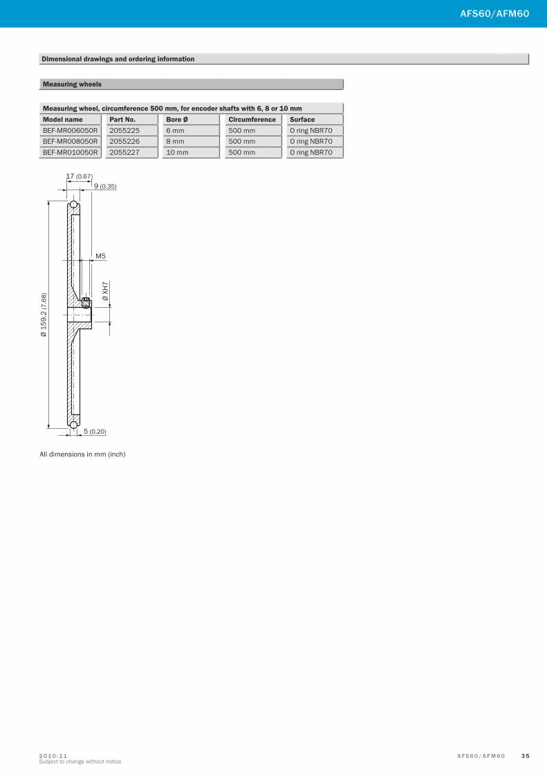
3 5A F S 6 0 / A F M 6 02 0 1 0 - 1 1Subject to change without notice
Measuring wheels
Measuring wheel, circumference 500 mm, for encoder shafts with 6, 8 or 10 mmModel name Part No. Bore Ø Circumference SurfaceBEF-MR006050R 2055225 6 mm 500 mm O ring NBR70BEF-MR008050R 2055226 8 mm 500 mm O ring NBR70BEF-MR010050R 2055227 10 mm 500 mm O ring NBR70
Ø 15
9.2
(7.6
8)
All dimensions in mm (inch)
Ø XH
7
M5
5 (0.20)
9 (0.35)17 (0.67)
AFS60/AFM60
Dimensional drawings and ordering information
SICK AG | Waldkirch | Germany | www.sick.com
8012
885/
2010
-11-
03 ∙
SS/M
D (2
010-
11) ∙
A4
2c in
t35 Australia
Phone +61 3 9497 4100 1800 33 48 02 – tollfreeE-Mail [email protected]
Belgium/LuxembourgPhone +32 (0)2 466 55 66E-Mail [email protected]
BrasilPhone +55 11 3215-4900E-Mail [email protected]
Ceská RepublikaPhone +420 2 57 91 18 50E-Mail [email protected]
ChinaPhone +852-2763 6966E-Mail [email protected]
DanmarkPhone +45 45 82 64 00E-Mail [email protected]
DeutschlandPhone +49 211 5301-301E-Mail [email protected]
EspañaPhone +34 93 480 31 00E-Mail [email protected]
FrancePhone +33 1 64 62 35 00E-Mail [email protected]
Great BritainPhone +44 (0)1727 831121E-Mail [email protected]
IndiaPhone +91–22–4033 8333E-Mail [email protected]
IsraelPhone +972-4-999-0590E-Mail [email protected]
ItaliaPhone +39 02 27 43 41E-Mail [email protected]
JapanPhone +81 (0)3 3358 1341E-Mail [email protected]
NederlandsPhone +31 (0)30 229 25 44E-Mail [email protected]
Norge Phone +47 67 81 50 00E-Mail [email protected]
ÖsterreichPhone +43 (0)22 36 62 28 8-0E-Mail [email protected]
PolskaPhone +48 22 837 40 50E-Mail [email protected]
Republic of KoreaPhone +82-2 786 6321/4E-Mail [email protected]
Republika SlovenijaPhone +386 (0)1-47 69 990E-Mail [email protected]
RomâniaPhone +40 356 171 120 E-Mail [email protected]
RussiaPhone +7 495 775 05 34E-Mail [email protected]
SchweizPhone +41 41 619 29 39E-Mail [email protected]
SingaporePhone +65 6744 3732E-Mail [email protected]
SuomiPhone +358-9-25 15 800E-Mail [email protected]
SverigePhone +46 10 110 10 00E-Mail [email protected]
TaiwanPhone +886 2 2375-6288E-Mail [email protected]
TürkiyePhone +90 216 587 74 00E-Mail [email protected]
United Arab EmiratesPhone +971 4 8865 878E-Mail [email protected]
USA/Canada/MéxicoPhone +1(952) 941-6780 1 800-325-7425 – tollfreeE-Mail [email protected]
More representatives and agencies in all major industrial nations at www.sick.com