Embed Size (px)
Citation preview
L0-0419-65169
Enclosure:
"ACRS Presentation: Chapter 4, Reactor OveNiew," PM-0419-65096, Revision 0
NuScale Power, LLC 1100 NE Circle Blvd., Suite 200 Corvallis, Oregon 97330 Office 541.360-0500 Fax 541.207.3928
www.nuscalepower.com
PM-0419-65096
Revision: 0
NuScale Nonproprietary
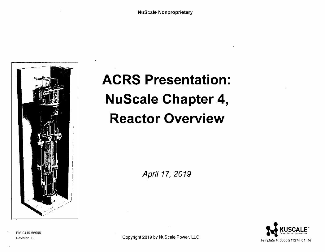
ACRS Presentation: NuScale Chapter 4, Reactor Overview
April 17, 2019
Copyright 2019 by NuScale Power, LLC. N ~!J,li.~~-~,§.
Template#: 0000-21727-F01 R4
2 PM-0419-65096
Revision: 0
Presentation Team
Larry Linik
Fuels Engineer
Allyson Callaway
Supervisor, Nuclear Analysis
Ken Rooks
Safety Analysis Engineer
Matthew Presson
Licensing Engineer
Copyright 2019 by NuScale Power, LLC. i-1 ~!:'.~.~~!:.~"
Template#: 0000-21727-F01 R4
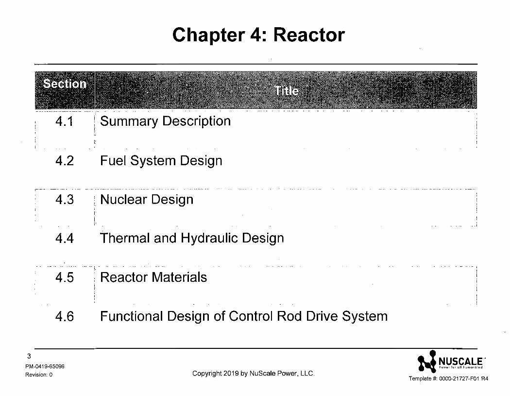
Chapter 4: Reactor
4.1 Summary Description
4.2 Fuel System Design
r----- -------- ----- --·-·;··------·-------· -···----·----- ------ - -- . - --··-~'"·----
4.3 :; Nuclear Design
4.4 Thermal and Hydraulic Design
• ·• • - • • • •• -• I •• "'" • • ·•• • • • •· ~ --
<,
4.5 , Reactor Materials
4.6 Functional Design of Control Rod Drive System
3
PM-0419-65096
Revision: 0 Copyright 2019 by NuScale Power, LLC.
- - - • - t
:-l ri!J.~.f.~-~.~ ' Template#: 0000-21727-F01 R4
4.1 - Summary Description
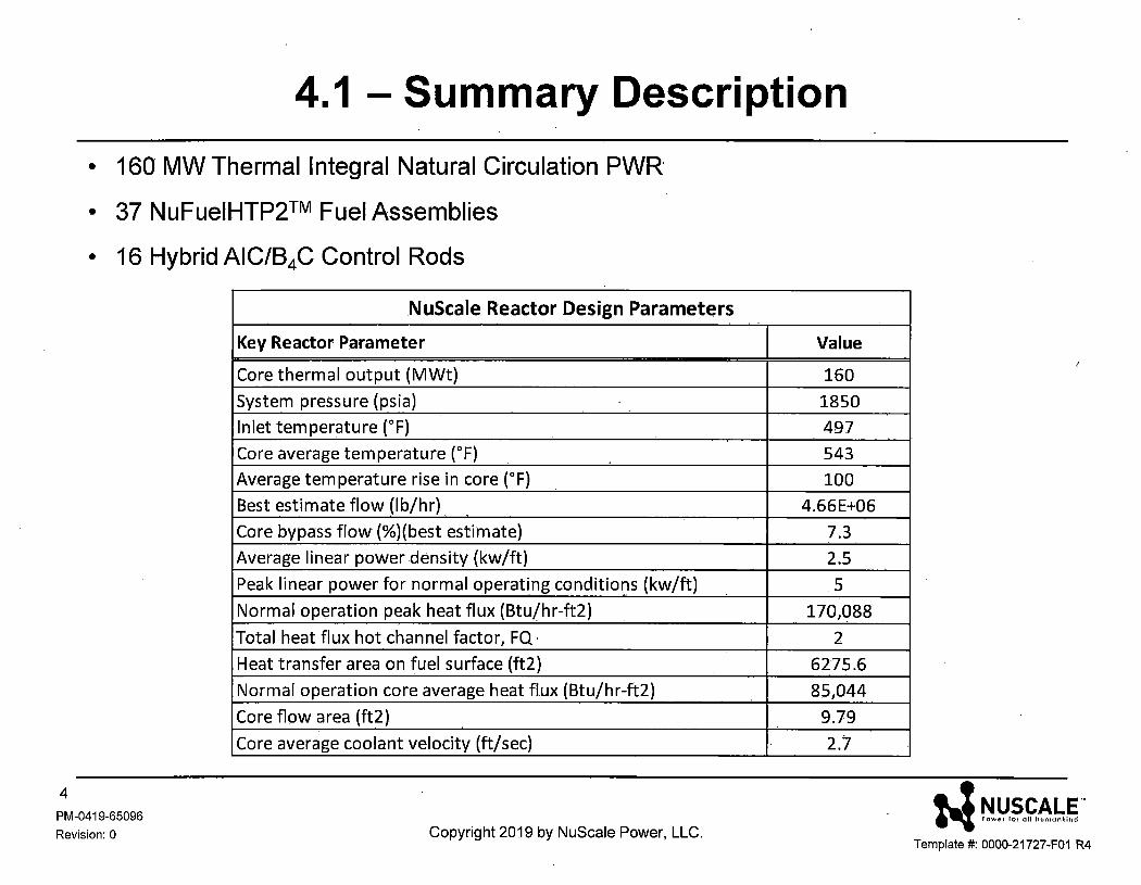
• 160 MW Thermal Integral Natural Circulation PWR·
• 37 NuFuelHTP2™ Fuel Assemblies
• 16 Hybrid AIC/84C Control Rods
4 PM-0419-65096
Revision: 0
NuScale Reactor Design Parameters
Key Reactor Parameter
Core thermal output (MWt)
System pressure (psia)
Inlet temperature (°F)
Core average temperature (°F)
Average temperature rise in core (°F)
Best estimate flow (lb/hr)
Core bypass flow (%)(best estimate)
Average linear power density (kw/ft)
Peak linear power for normal operating conditions (kw/ft)
Normal operation peak heat flux (Btu/hr-ft2)
Total heat flux hot channel factor, FQ ·
Heat transfer area on fuel surface (ft2)
Normal operation core average heat flux (Btu/hr-ft2)
Core flow area (ft2)
Core average coolant velocity (ft/sec)
Copyright 2019 by NuScale Power, LLC.
Value
160
1850
497
543
100
4.66E+06
7.3
2.5
5
170,088
2
6275.6
85,044
9.79
2.7
N ~!!.~.~~!:.~. Template#: 0000-21727-F01 R4
4.2 - Summary Description
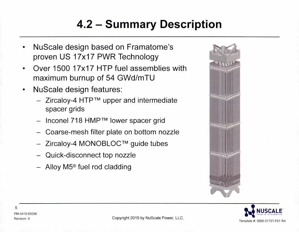
• NuScale design based on Framatome's proven US 17x17 PWR Technology
• Over 1500 17x17 HTP fuel assemblies with maximum burnup of 54 GWd/mTU
• NuScale design features: - Zircaloy-4 HTP™ upper and intermediate
spacer grids
- lnconel 718 HMP™ lower spacer grid
- Coarse-mesh filter plate on bottom nozzle
- Zircaloy-4 MONOBLOC™ guide tubes
Quick-disconnect top nozzle
- Alloy M5® fuel rod cladding
5
PM-0419-65096
Revision : 0 Copyright 2019 by NuScale Power, LLC.
• ! NUSCALE .. "'I Sowo , lo , ull hcmo,•k;nd
Template#: 0000-21 727-F01 R4
4.2 - Fuel Assembly Design
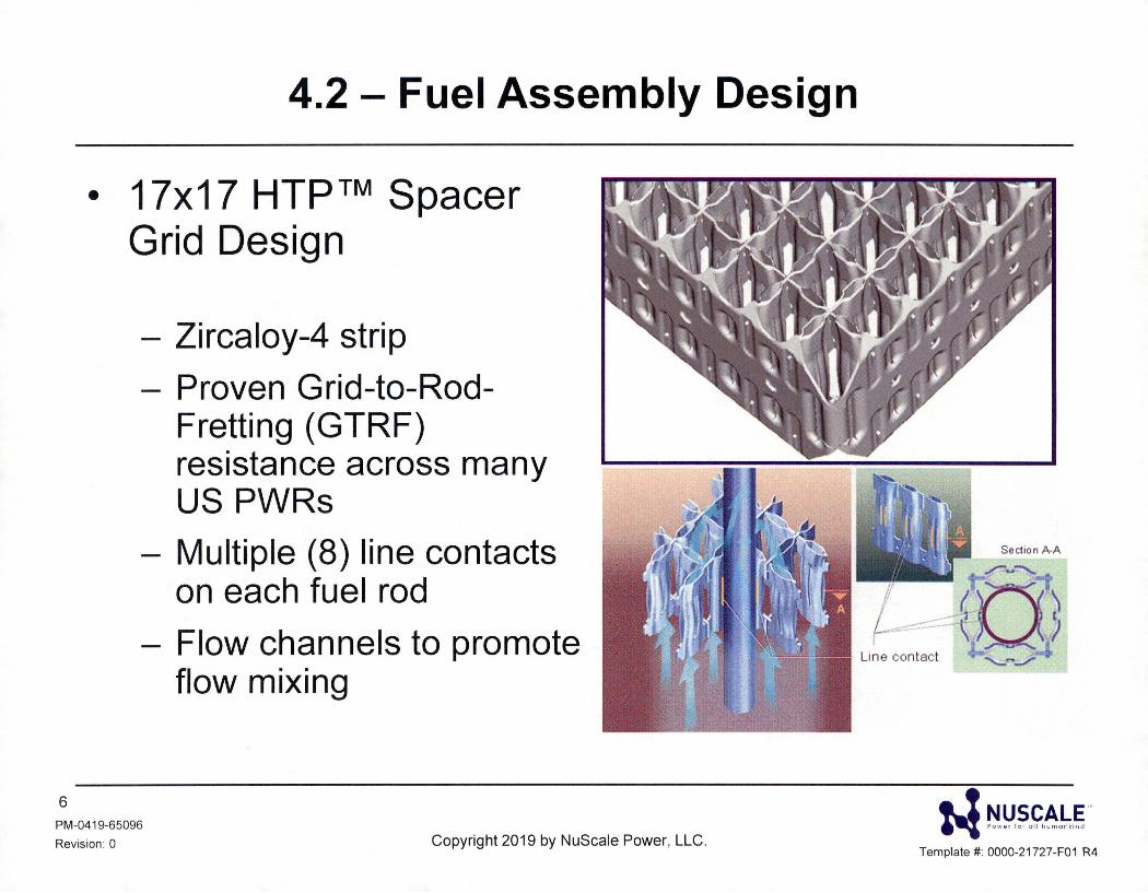
• 17x17 HTP™ Spacer Grid Design
- Zircaloy-4 strip
- Proven Grid-to-Rod-Fretting (GTRF) resistance across many US PWRs
- Multiple (8) line contacts on each fuel rod
- Flow channels to promote flow mixing
6
PM-0419-65096
Revision : 0 Copyright 2019 by NuScale Power, LLC. w ~!J.~"~~"~g-
Template # : 0000-21727-F01 R4
4.2 - Fuel Assembly Design
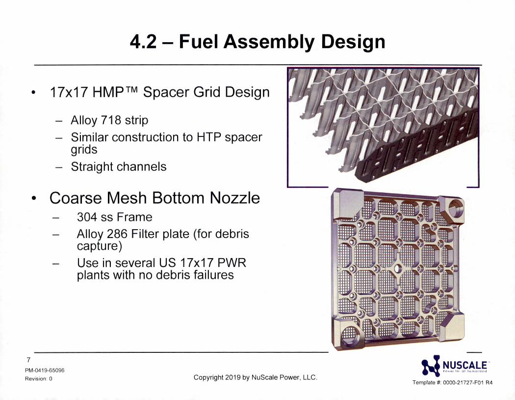
• 17x17 HMP™ Spacer Grid Design
- Alloy 718 strip - Similar construction to HTP spacer
grids - Straight channels
• Coarse Mesh Bottom Nozzle 304 ss Frame
7
PM-0419-65096
Revision : 0
Alloy 286 Filter plate (for debris capture) Use in several US 17x17 PWR plants with no debris failures
Copyright 2019 by NuScale Power, LLC.
a! NUSCALE .. ~ Sow o , l o , u fl h c mu,· k;nd
Template#: 0000-21727-F01 R4
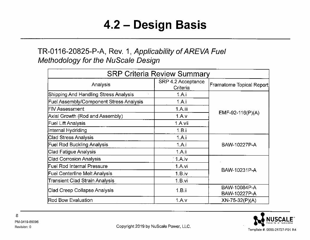
4.2 - Design Basis
TR-0116-20825-P-A, Rev. 1, Applicability of AREVA Fuel Methodology for the NuScale Design
8
PM-0419-65096
Revision: 0
SRP Criteria Review Summary Analysis
SRP 4.2 Acceptance Criteria
Shipping And Handling Stress Analysis 1.A.i
Fuel Assembly/Component Stress Analysis 1.A.i
FIV Assessment 1.A.iii
Axial Growth (Rod and Assembly) 1.A.v
Fuel Lift Analysis 1.A.vii
Internal Hydriding 1.B.i
Clad Stress Analysis 1.A.i
Fuel Rod Buckling Analysis 1.A.i
Clad Fatigue Analysis 1.A.ii
Clad Corrosion Analysis · 1.A.iv
Fuel Rod Internal Pressure 1.A.vi
Fuel Centerline Melt Analysis 1.B.iv
Transient Clad Strain Analysis 1.B.vi
Clad Creep Collapse Analysis 1.B.ii
Rod Bow Evaluation 1.A.v
Copyright 2019 by NuScale Power, LLC.
Framatome Topical Report
EM F-92-116(P)(A)
BAW-10227P-A
BAW-10231 P-A
BAW-10084P-A BAW-10227P-A XN-75-32(P)(A)
i-1 ~!!?.~~-~,§ ' Template#: 0000-21727-F01 R4
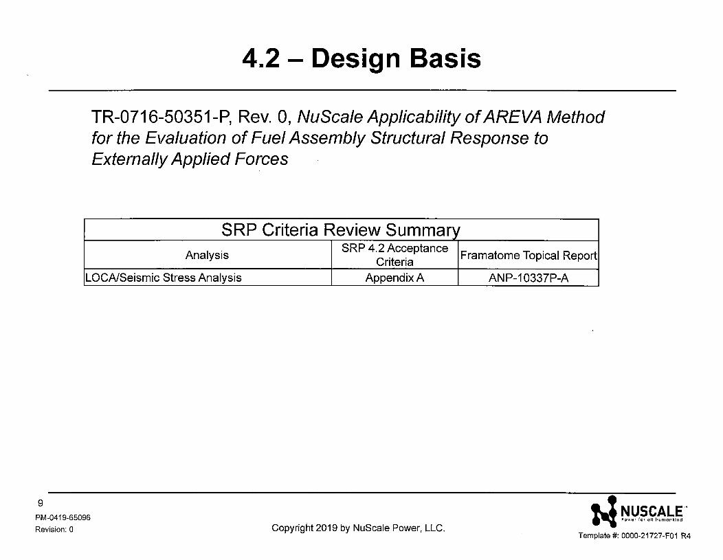
4.2 - Design Basis
TR-0716-50351-P, Rev. 0, NuScale Applicability of AREVA Method for the Evaluation of Fuel Assembly Structural Response to Externally Applied Forces
SRP Criteria Review Summary Analysis
SRP 4.2 Acceptance Framatome Topical Report
Criteria LOCA/Seismic Stress Analysis Appendix A ANP-10337P-A
9
PM-0419-65096
Revision: 0 Copyright 2019 by NuScale Power, LLC. i-1 ~!J,~,~-~b§'
Template#: 0000-21727-F01 R4
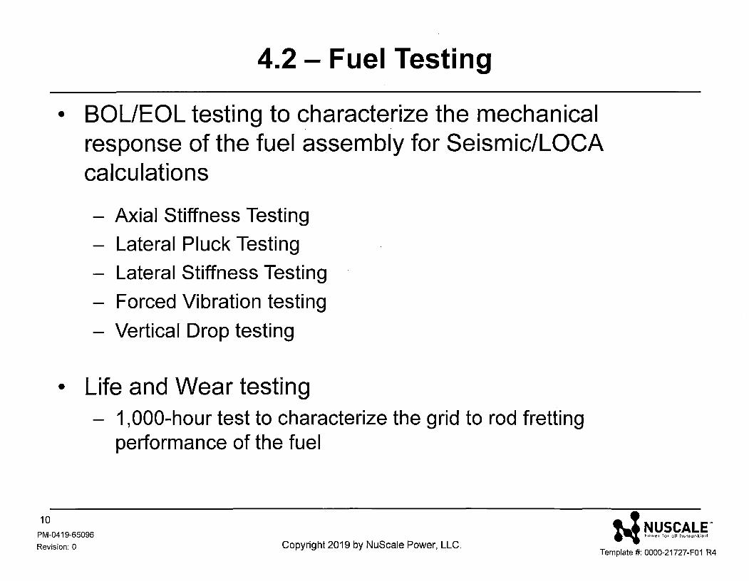
4.2 - Fuel Testing
• BOL/EOL testing to characte_rize the mechanical response of the fuel assembly for Seismic/LOCA calculations
- Axial Stiffness Testing
- Lateral Pluck Testing
- Lateral Stiffness Testing
- Forced Vibration testing
- Vertical Drop testing
• Life and Wear testing - 1,000-hour test to characterize the grid to rod fretting
performance of the fuel
w ~!:'.~0~~01,,g o
10
PM-0419-65096
Revision: 0 Copyright 2019 by NuScale Power, LLC. Template#: 0000-21727-F01 R4
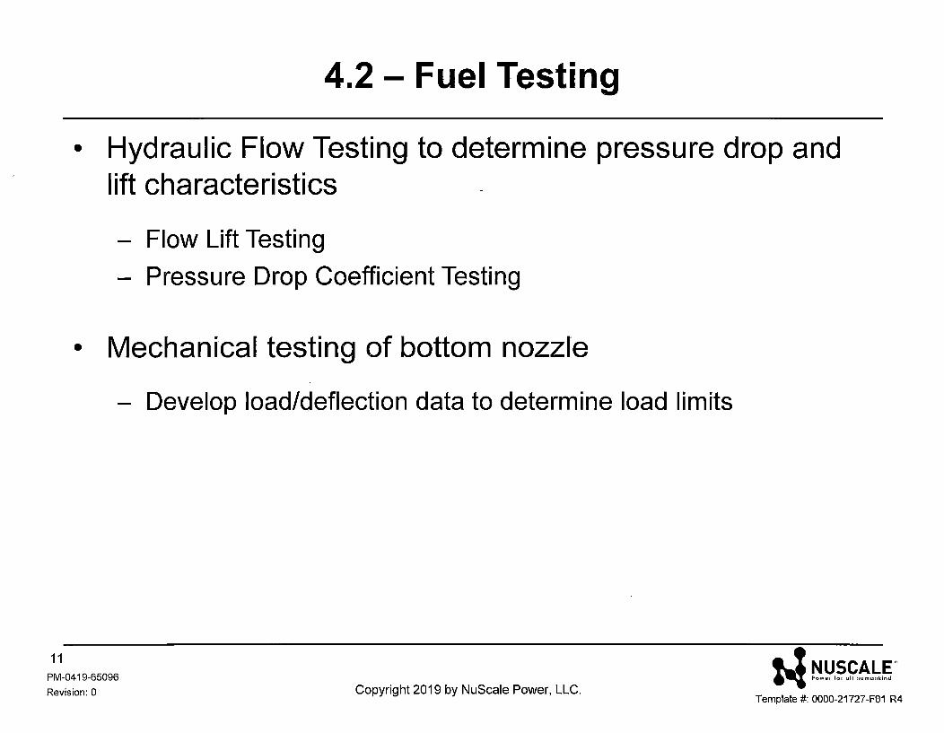
4.2 - Fuel Testing
• Hydraulic Flow Te.sting to determine pressure drop and lift characteristics
- Flow Lift Testing
- Pressure Drop Coefficient Testing
• Mechanical testing of bottom nozzle
- Develop load/deflection data to determine load limits
11
PM-0419-65096
Revision: 0 Copyright 2019 by NuScale Power, LLC. N ~!J.~"~"!M~ "
Template#: 0000-21727-F01 R4
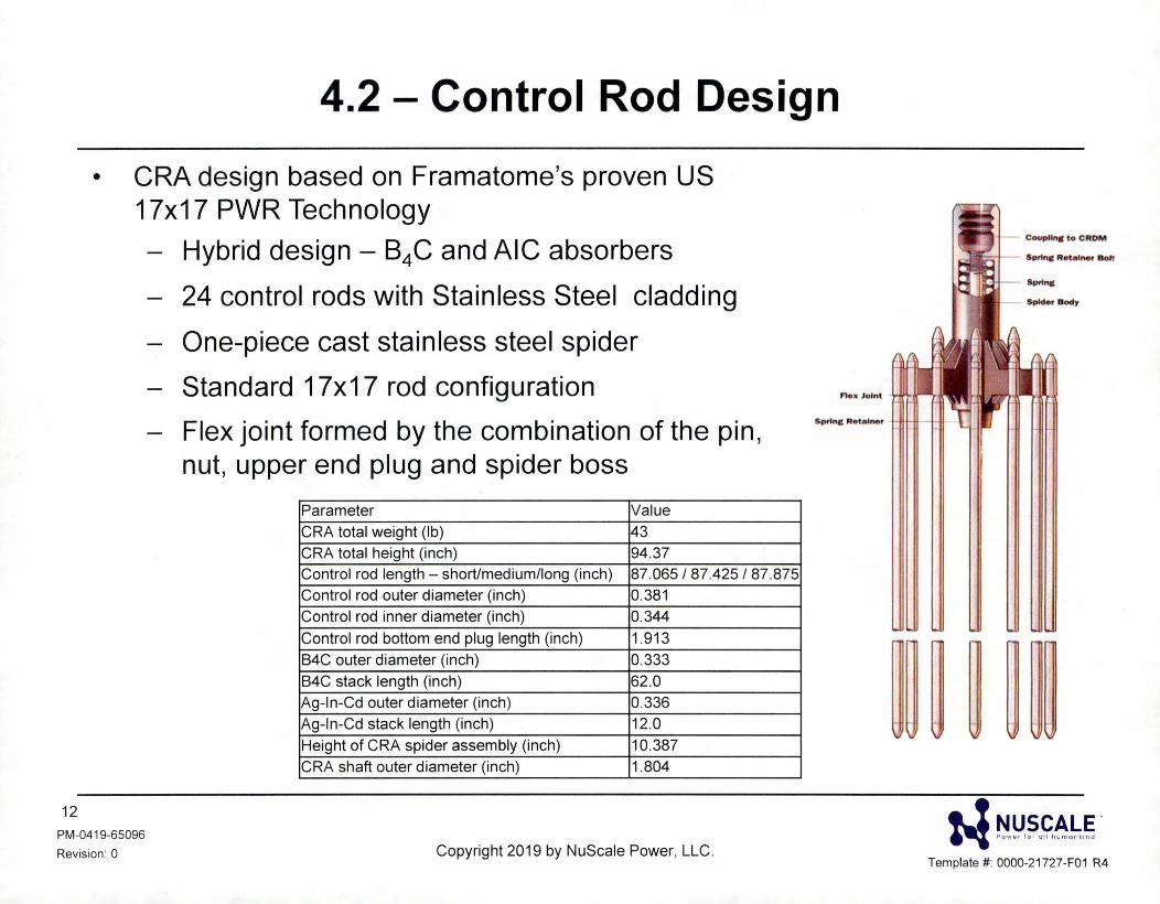
4.2 - Control Rod Design
• CRA design based on Framatome's proven US 17x17 PWR Technology
12
PM-0419-65096
Revision: 0
Hybrid design - B4C and AIC absorbers
24 control rods with Stainless Steel cladding
One-piece cast stainless steel spider
Standard 17x17 rod configuration
Flex joint formed by the combination of the pin, nut, upper end plug and spider boss
Parameter Value
CRA total weight (lb) 43 CRA total height (inch) 94.37 Control rod length - short/medium/long (inch) 87.065 I 87.425 I 87.875 Control rod outer diameter (inch) 0.381
Control rod inner diameter (inch) 0.344
Control rod bottom end plug length (inch) 1.913
B4C outer diameter (inch) 0.333
B4C stack length (inch) 62.0 Ag-In-Cd outer diameter (inch) 0.336
Ag-In-Cd stack length (inch) 12.0
Height of CRA spider assembly (inch) 10.387 CRA shaft outer diameter (inch) 1.804
Copyright 2019 by NuScale Power, LLC.
CoupUn. to CROM
- SprlnC Retainer Bolt
- Spider Body
Flex Joint
• ! NUSCALE .. ~ Sow•• lo • all J,cma ",;nu
Template #: 0000-21727-F01 R4
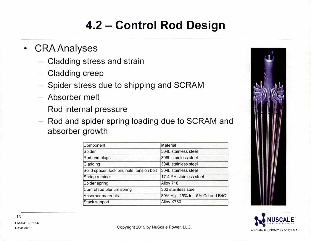
4.2 - Control Rod Design
• CRA Analyses
13
PM-0419-65096
Revision : 0
Cladding stress and strain
Cladding creep Spider stress due to shipping and SCRAM
Absorber melt Rod internal pressure Rod and spider spring loading due to SCRAM and absorber growth
Component Material
Spider 304L stainless steel
Rod end plugs 308L stainless steel
Cladding 304L stainless steel
Solid spacer, lock pin, nuts, tension bolt 304L stainless steel
Spring retainer 17-4 PH stainless steel
Spider spring Alloy 718
Control rod plenum spring 302 stainless steel
Absorber materials 80% Ag - 15% In - 5% Cd and B4C
Stack support Alloy X750
Copyright 2019 by NuScale Power, LLC. N ~~.~.~~.L..~ ..
Template#: 0000-21727-F01 R4
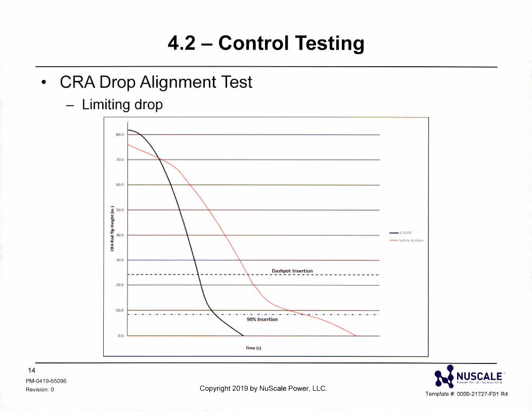
4.2 - Control Testing
• CRA Drop Alignment Test - Limiting drop
14 PM-0419-65096
Revision : 0
!'. 500 t------+-----'~ ----------------j, ~
f 400 t---------lr-----"t----------------1 .. C
rs
11me (s)
Copyright 2019 by NuScale Power, LLC.
• ! NUSCALE '" ~ Sow • • lo , u ll l>cma, , , ;na
Template#: 0000-21727-F01 R4
4.2 - Conclusion
• Proven Framatome 17X17 components
• NRC Accepted Framatome codes and methods
• Standard Framatome fuel design, analysis, prototype fabrication, and testing
• Standard CRA design, analysis, and testing
• Both fuel and CRA designs are essentially reduced height versions of current designs
15 PM-0419-65096
Revis ion: 0 Copyright 2019 by NuScale Power, LLC. w r!!:'.?"~A~g ..
Template#: 0000-21727-F01 R4
4.3 - Design Basis and Methods • Core design conforms to NUREG-0800, SRP 4.3 guidance
• Latest version of Studvik's Core Management Suite (CMS5) - CASM05 and SIMULATES steady-state neutronics software
- CMS5 analytical methods for neutronic analysis are approved for use
- Topical Report TR-0616-48793-P-A "Nuclear Analysis Codes and Methods
16 PM-0419-65096
Revision: 0
Qualification"
Copyright 2019 by NuScale Power, LLC. i-1 ~!:'.~.~.~-~.~ ''
Template#: 0000-21727-F01 R4
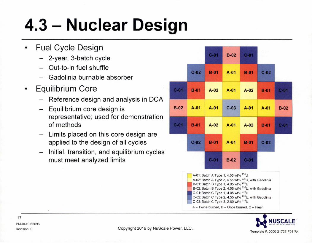
4.3 - Nuclear Design • Fuel Cycle Design
2-year, 3-batch cycle
Out-to-in fuel shuffle
Gadolinia burnable absorber
• Equilibrium Core
17
PM-0419-65096
Revision : 0
Reference design and analysis in DCA
Equilibrium core design is representative; used for demonstration of methods Limits placed on this core design are applied to the design of all cycles
Initial , transition , and equilibrium cycles must meet analyzed limits
Copyright 2019 by NuScale Power, LLC .
A-01 : Batch A Type 1, 4 .05 wt% 235U
A-02: Batch A Type 2, 4 .55 wt% 235U, with Gadolinia B-01: Batch B Type 1, 4.05 wt% 235U B-02: Batch B Type 2, 4.55 wt% 235U, with Gadolinia C-01 : Batch c Type 1, 4.05 wt% 235U C-02: Batch C Type 2, 4.55 wt% 235U, with Gadolinia C-03: Batch C Type 3, 2.60 wt% 235U
A - Twice burned, B - Once burned, C - Fresh
• ! NUSCALE .. "'I , ow •• lo , oll hs"'a,· k;na
Template#: 0000-21727-F01 R4
4.3 - Core Design Limits • Cycles are designed to meet constraints and requirements
- Energy output and burnup
- Enrichment limits, zoning, and gadolinia loading
• Core design limits are verified for each cycle to confirm the safety analysis bases and ensure specified acceptable fuel design limits (SAFDLs) are not exceeded - Moderator temperature and Doppler reactivity coefficients
- Kinetics parameters
- Critical and refueling boron concentration
- Axial and radial peaking
- Shutdown margin and long term shutdown capability
- Event-specific limits (i.e. power peaking)
• Core design limits are set to ensure that sufficiently conservative values are analyzed
18 PM-0419-65096
Revision : 0 Copyright 2019 by NuScale Power, LLC.
• ! NUSCALE .. ~ S ow •, lo , ull h c mo,-,;nd
Template#: 0000-21727-F01 R4
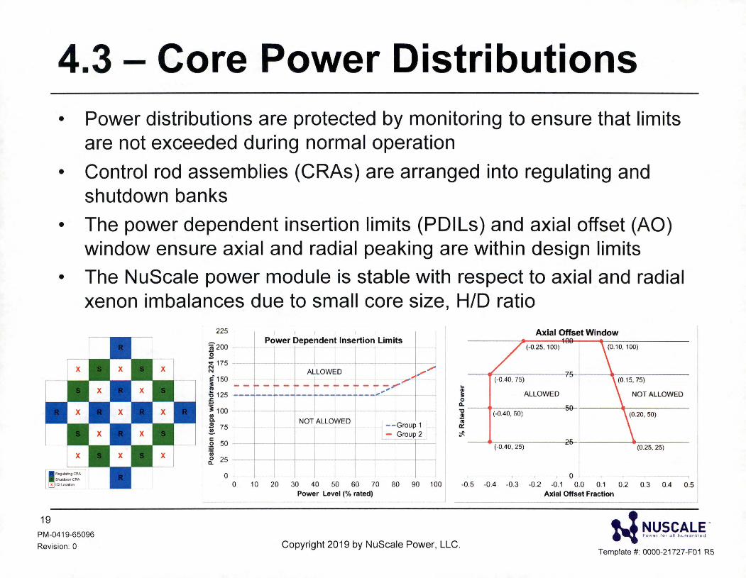
4.3 - Core Power Distributions • Power distributions are protected by monitoring to ensure that limits
are not exceeded during normal operation
• Control rod assemblies (CRAs) are arranged into regulating and shutdown banks
• The power dependent insertion limits (POils) and axial offset (AO) window ensure axial and radial peaking are within design limits
• The NuScale power module is stable with respect to axial and radial xenon imbalances due to small core size, H/D ratio
225
j 200 .s ~ 175 N
c" 150 I -o 125 .r;
I j 100 Ill Cl.
~ 75 .!!!. 5 50 :;::; 'in ~ 25
0
I
1 -I
r-::-I I I I
I
f
I I I I I I I Axial Offset Window Power Dependent lnsertio n Limits
. AL[ l !- - -- ·-1-L ------- __ i ___ --
NOT ALLOWED --Group 1J - Group 2
(-040, 25) (0.25, 25)
-
r 1 r 1 0 r r , 0 10 20 30 40 50 60 70 80 90 100 -0.5 -0.4 -0.3 -0.2 -0.1 0.0 0.1 0.2 0.3 0.4 0.5
19
PM-0419-65096
Revision: 0
Power Level (% rated) Axial Offset Fraction ~--- -- -- --- -- --- -- ---------~
Copyright 2019 by NuScale Power, LLC. w ~!J.?"S~.~.~
Template#: 0000-21727-F01 R5
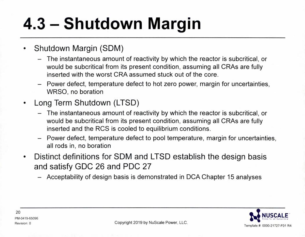
4.3 - Shutdown Margin • Shutdown Margin (SOM)
- The instantaneous amount of reactivity by which the reactor is subcritical, or would be subcritical from its present condition , assuming all CRAs are fully inserted with the worst CRA assumed stuck out of the core.
- Power defect, temperature defect to hot zero power, margin for uncertainties, WRSO, no boration
• Long Term Shutdown (LTSD) - The instantaneous amount of reactivity by which the reactor is subcritical , or
would be subcritical from its present condition , assuming all CRAs are fully inserted and the RCS is cooled to equilibrium conditions.
- Power defect, temperature defect to pool temperature, margin for uncertainties, all rods in , no boration
• Distinct definitions for SOM and LTSD establish the design basis and satisfy GDC 26 and PDC 27 - Acceptability of design basis is demonstrated in DCA Chapter 15 analyses
20
PM-0419-65096
Revision : 0 Copyright 2019 by NuScale Power, LLC. N !'!!:'.~"~-~"~.§ -
Template#: 0000-21727-F01 R4
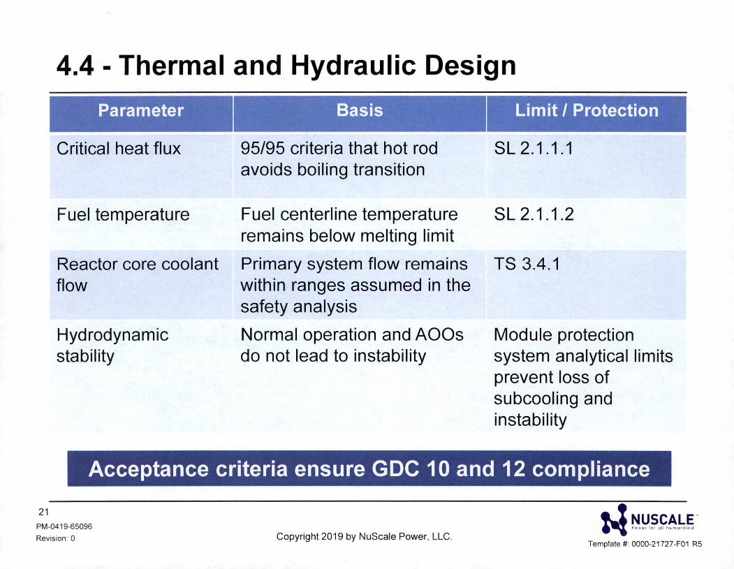
4.4 - Thermal and Hydraulic Design
Parameter
Critical heat flux
Fuel temperature
Reactor core coolant flow
Hydrodynamic stability
Basis
95/95 criteria that hot rod avoids boiling transition
Fuel centerline temperature remains below melting limit
Primary system flow remains within ranges assumed in the safety analysis
Normal operation and AOOs do not lead to instability
Lim it / Protection
SL2.1.1.1
SL2.1.1.2
TS 3.4.1
Module protection system analytical limits prevent loss of subcooling and instability
Acceptance criteria ensure GDC 10 and 12 compliance
21
PM-0419-65096
Revision : 0 Copyright 2019 by NuScale Power, LLC. w ~!:'.~.f~!_g"
Template#: 0000-21 727-F01 R5
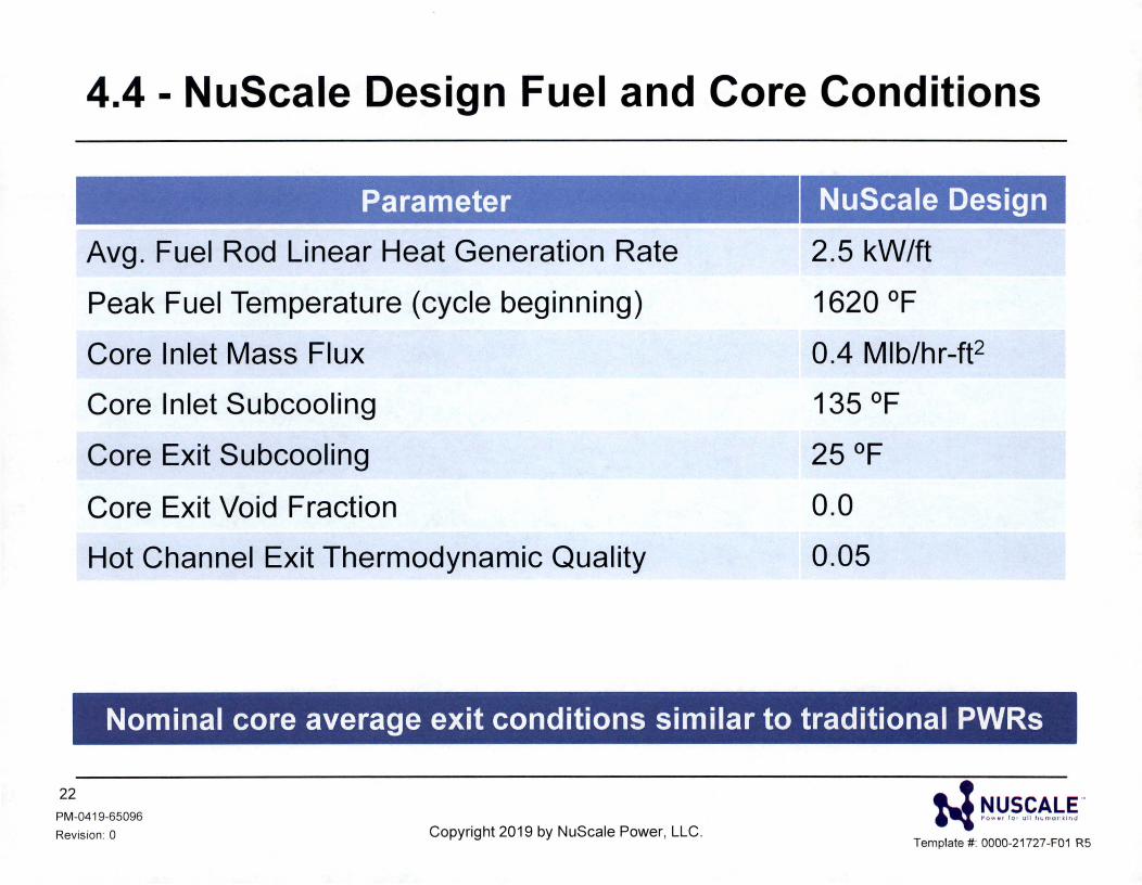
4.4 - NuScale Design Fuel and Core Conditions
Parameter
Avg. Fuel Rod Linear Heat Generation Rate
Peak Fuel Temperature (cycle beginning)
Core Inlet Mass Flux
Core Inlet Subcooling
Core Exit Subcooling
Core Exit Void Fraction
Hot Channel Exit Thermodynamic Quality
NuScale Design
2.5 kW/ft
1620 °F
0.4 Mlb/hr-ft2
135 °F
25 °F
0.0
0.05
Nominal core average exit conditions similar to traditional PWRs
22
PM-0419-65096
Revision: 0 Copyright 2019 by NuScale Power, LLC. N ~!J.~.~.~-~.r
Template#: 0000-21727-F01 R5
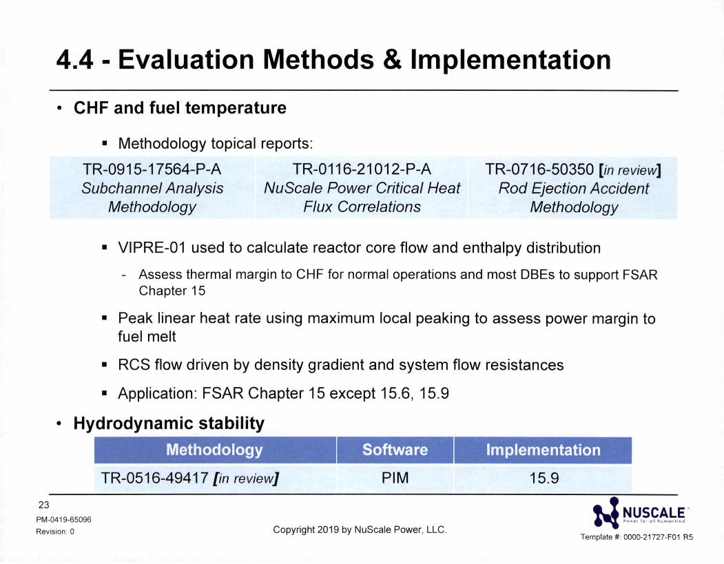
4.4 - Evaluation Methods & Implementation
• CHF and fuel temperature
• Methodology topical reports:
TR-0915-17564-P-A TR-0116-21012-P-A Subchannel Analysis
Methodology NuScale Power Critical Heat
Flux Correlations
TR-0716-50350 [in review] Rod Ejection Accident
Methodology
• VIPRE-01 used to calculate reactor core flow and enthalpy distribution
- Assess thermal margin to CHF for normal operations and most DBEs to support FSAR Chapter 15
• Peak linear heat rate using maximum local peaking to assess power margin to fuel melt
• RCS flow driven by density gradient and system flow resistances
• Application: FSAR Chapter 15 except 15.6, 15.9
• Hydrodynamic stability
23 PM-0419-65096
Revision: 0
Methodology Software
TR-0516-49417 {in review] PIM
Copyright 2019 by NuScale Power, LLC.
Implementation
15.9
w ~!:'.r>.~~b.~. Template#: 0000-21727-F01 R5
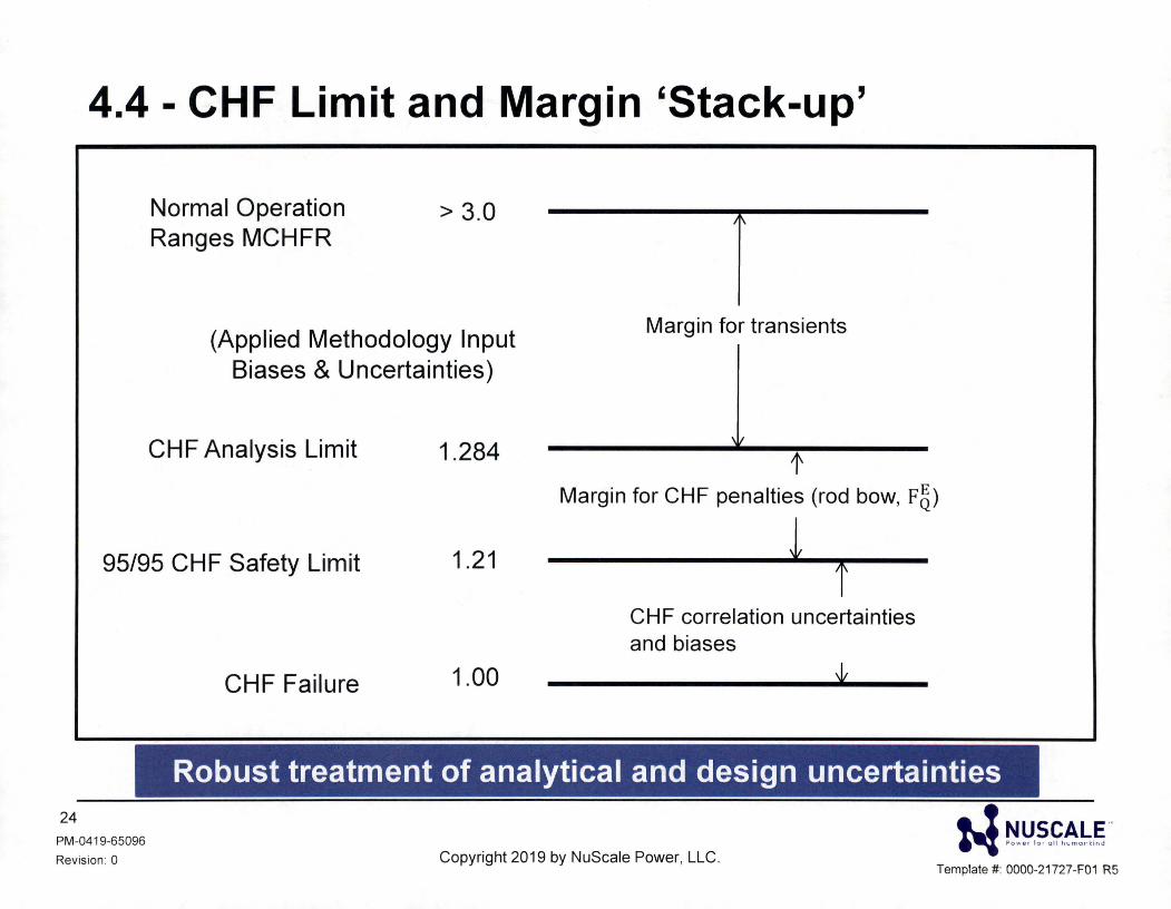
4.4 - CHF Limit and Margin 'Stack-up'
Normal Operation Ranges MCHFR
> 3.0
(Applied Methodology Input Biases & Uncertainties)
CHF Analysis Limit 1.284
I\
Margin for transients
' I
1' Margin for CHF penalties (rod bow, F5)
95/95 CHF Safety Limit 1.21
CHF Failure 1.00
l t
CHF correlation uncertainties and biases
Robust treatment of analytical and design uncertainties 24
PM-0419-65096
Revision : 0 Copyright 2019 by NuScale Power, LLC.
• ! NUSCALE '" ~ e ow •• lo, ull hcma,- ,;nd
Template#: 0000-21 727-F01 R5
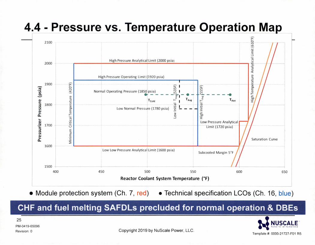
4.4 - Pressure vs. Temperature Operation M_ a,_ 2100
High Pressure Analytical, Limit (2000 psia ) 2000 · • .... · · - ----------------------------------·
-n:, "iii a. -(IJ
""
1900
:::J 1800 11'1 11'1 (IJ
"" Q.
"" (IJ
-~ 1700 :::J 11'1 11'1 (IJ
"" Q.
1600
~ .3 ~ (]J a. E (]J
I-CU u
·.;:; ·c u E ::i E C
~
H\gh Pressure Operating Limit (1920 psia)
; ~ I [ U:-
Norllflal Operating Pressure (1850!psia) ~ I ! ~ er - - - - - !T1 - • -t ~ - - - - •
! <( I ~
i T Cold I- I T Avg j := T Hot
Low Nonnal Pcessuce (1780 psia) 1 L - -1 · 1w '"""" Analytical
·~-- L1m1t (1720 psi aJ
' ' i Low Low Pressure Analytica \ Limit (1600 psia) Subcooled Margin 5°F
rn C <I:
~ ::i .., ~ ···· -··or · ·· a. E (]J
I-
Saturation Curve
1500 L ----- --i- -- ___ -+-- ______ ---t-------~~-----------i
400 450 500 550 600 650
Reactor Coolant System Temperature (°F)
• Module protection system (Ch. 7, red ) • Technical specification LCOs (Ch . 16, blue)
CHF and fuel melting SAFDLs precluded for normal operation & DBEs 25
PM-0419-65096
Revision : 0 Copyright 2019 by NuScale Power, LLC.
• ! NUSCALE '" ~ e ow o, lo, u lt h,ma,· k;na
Template#: 0000-21727-F01 R5
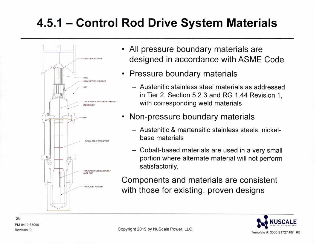
4.5.1 - Control Rod Drive System Materials
26
PM-0419-65096
Revision : 0
(
0
CROM SIJ'PORT FRAME
- TYPICAL CONTROL ROO ORNE (CRO) SHAFT
PRESSURIZER
----- TYPICAL CRO SliAFT SUPPORT
TYPICAL CONTROL ROil ASSEM81. Y GUIDE TUIIE
TYPICAL F\.El A.SSEMBL Y
• All pressure boundary materials are designed in accordance with ASME Code
• Pressure boundary materials
- Austenitic stainless steel materials as addressed in Tier 2, Section 5.2.3 and RG 1.44 Revision 1, with corresponding weld materials
• Non-pressure boundary materials
- Austenitic & martensitic stainless steels, nickelbase materials
- Cobalt-based materials are used in a very small portion where alternate material will not perform satisfactorily.
Components and materials are consistent with those for existing, proven designs
Copyright 2019 by NuScale Power, LLC. w ~!:'.~.~~!:.~.
Template#: 0000-21727-F01 R5
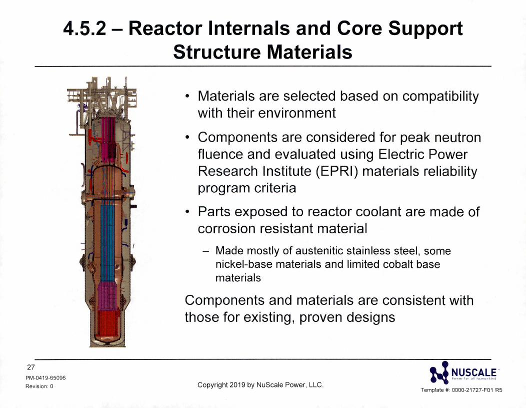
4.5.2 - Reactor Internals and Core Support Structure Materials
27 PM-0419-65096
Revision: 0
• Materials are selected based on compatibility with their environment
• Components are considered for peak neutron fluence and evaluated using Electric Power Research Institute (EPRI) materials reliability program criteria
• Parts exposed to reactor coolant are made of corrosion resistant material
- Made mostly of austenitic stainless steel, some nickel-base materials and limited cobalt base materials
Components and materials are consistent with those for existing, proven designs
Copyright 2019 by NuScale Power, LLC. N ~!:'.~.£~b~ -
Template#: 0000-21727-F01 R5
28 PM-0419-65096
Revis ion: 0
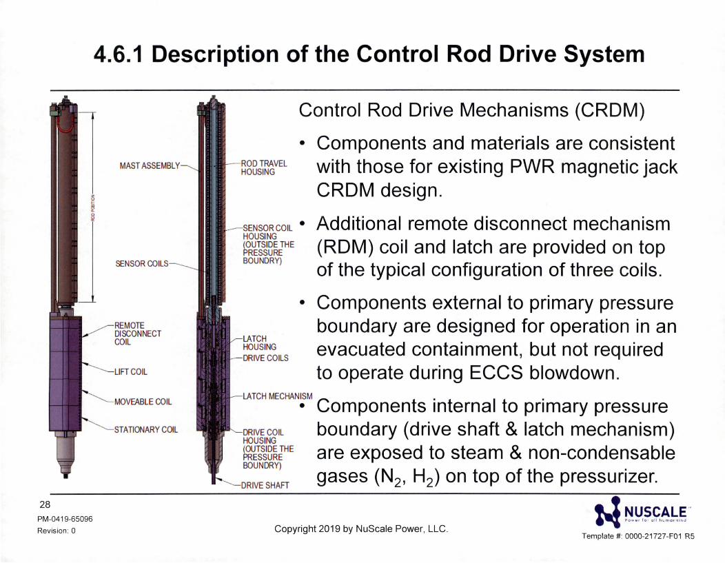
4.6.1 Description of the Control Rod Drive System
MAST ASSEMBLY
SENSOR COILS
REMOTE DISCONNECT COIL
LIFT COIL
MOVEABLE COIL
STATIONARY COIL
Control Rod Drive Mechanisms (CROM)
• Components and materials are consistent with those for existing PWR magnetic jack CROM design.
SENSOR COIL • HOUSING (OUTSIDE THE PRESSURE BOUNDRY)
Additional remote disconnect mechanism (ROM) coil and latch are provided on top of the typical configuration of three coils.
LATCH HOUSING
- DRIVE COILS
• Components external to primary pressure boundary are designed for operation in an evacuated containment, but not required to operate during ECCS blowdown.
LATCH MECHANISM , •
• Components internal to primary pressure DRIVE COIL HOUSING (OUTSIDE THE PRESSURE BOUNDRY)
boundary (drive shaft & latch mechanism) are exposed to steam & non-condensable gases (N2, H2) on top of the pressurizer.
w ~!:'.~.~~!;.§" Template #: 0000-21727-F01 R5
Copyright 2019 by NuScale Power, LLC.
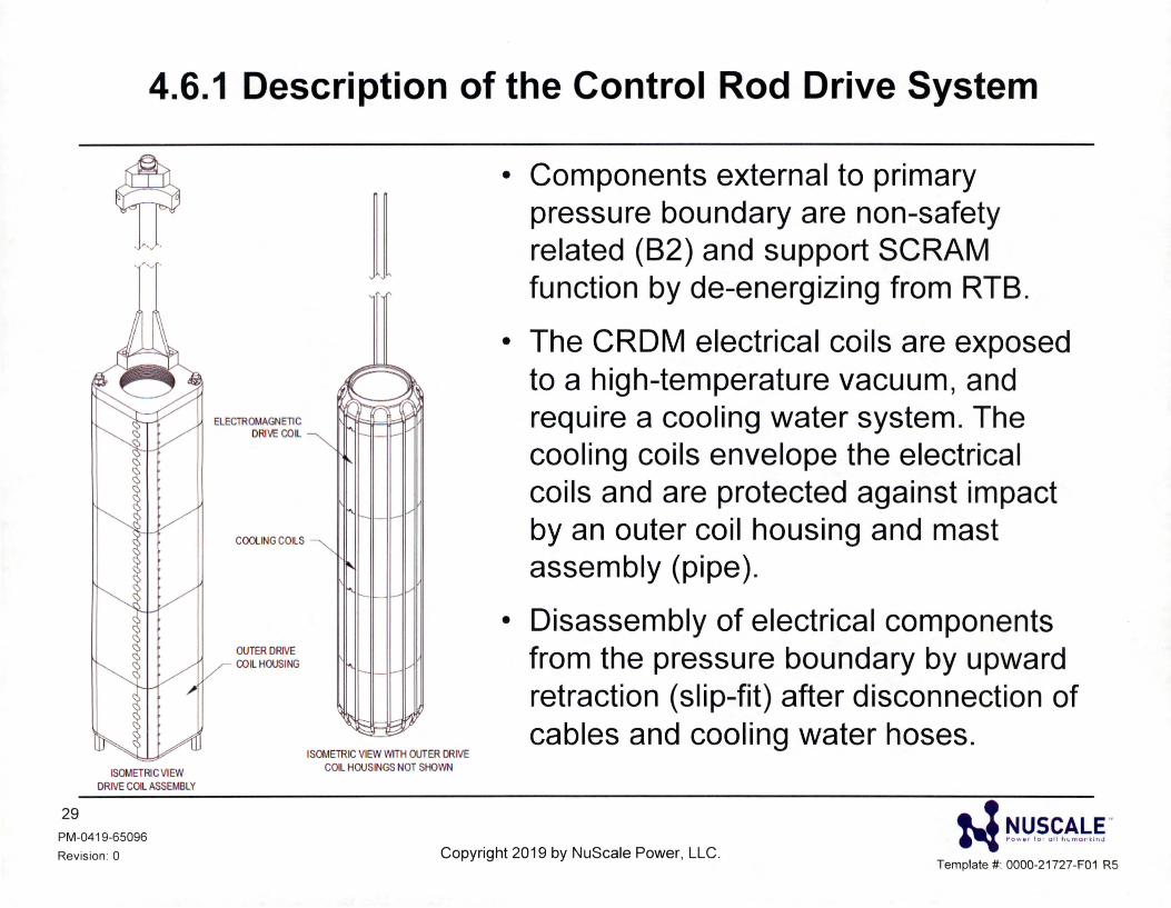
4.6.1 Description of the Control Rod Drive System
' ,.,., .
• r .. ., •
ISOMETRIC VIEW DRIVE COIL ASSEMBLY
29
PM-0419-65096
Revision : 0
ELECTROMAGNETIC DRIVE COIL
COOLING COILS
OUTERDRNE COIL HOUSING
II
ISOMETRIC VIEW WITH OUTER DRIVE COIL HOUSINGS NOT SHOWN
• Components external to primary pressure boundary are non-safety related (B2) and support SCRAM function by de-energizing from RTB.
• The CROM electrical coils are exposed to a high-temperature vacuum, and require a cooling water system. The cooling coils envelope the electrical coils and are protected against impact by an outer coil housing and mast assembly (pipe).
• Disassembly of electrical components from the pressure boundary by upward retraction (slip-fit) after disconnection of cables and cooling water hoses.
Copyright 2019 by NuScale Power, LLC. w ri!J.~.£~.~.~ ..
Template#: 0000-21727-F01 R5
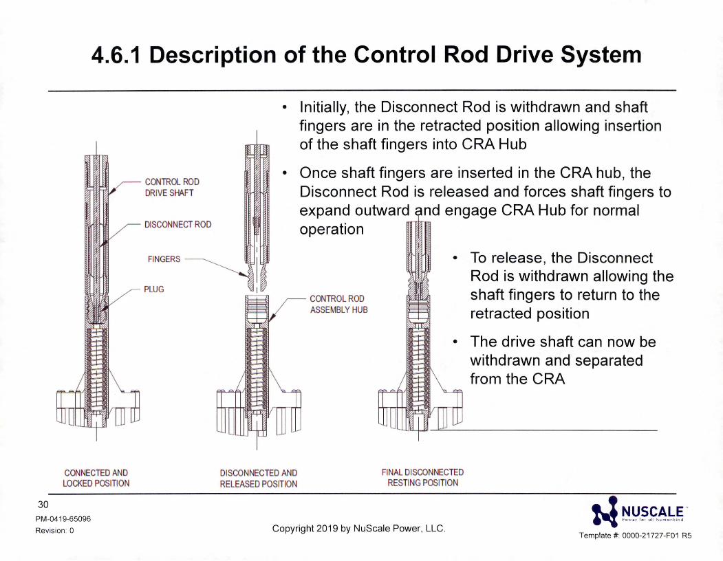
4.6.1 Description of the Control Rod Drive System
CONNECTED AND LOCKED POSITION
30
PM-041 9-65096
Revision : 0
CONTROL ROD DRIVE SHAFT
DISCONNECT ROD
FINGERS
PLUG
• Initially, the Disconnect Rod is withdrawn and shaft fingers are in the retracted position allowing insertion of the shaft fingers into CRA Hub
• Once shaft fingers are inserted in the CRA hub, the Disconnect Rod is released and forces shaft fingers to expand outward nd engage CRA Hub for normal operation
DISCONNECTED AND RELEASED POSITION
CONTROL ROD ASSEMBLY HUB
• To release, the Disconnect Rod is withdrawn allowing the shaft fingers to return to the retracted position
• The drive shaft can now be withdrawn and separated from the CRA
FINAL DISCONNECTED RESTING POSITION
• ! NUSCALE" ~ So w • • lo , ull l,cmo n,;n J
Copyright 2019 by NuScale Power, LLC. Template #: 0000-21727-F01 R5
COL Item 4.2-1
31 PM-0419-65096
Revision : 0
Chapter 4 - COL Items
• A COL applicant that references the NuScale Power Plant design certification and wishes to utilize non-baseload operations will provide justification for the fuel performance codes and methods corresponding to the desired operation.
Copyright 2019 by NuScale Power, LLC.
• ! NUSCALE .. ~ S ow o, lo , ull hcmunk;na
Template#: 0000-21727-F01 R5
• AO - Axial Offset
• AOO - Anticipated Operational Occurrences
• ASME - American Society of Mechanical Engineers
• BOL - Beginning of Life
• CHF - Critical Heat Flux
• COL - Combined License
• CRA - Control Rod Assembly
• CRDM - Control Rod Drive Mechanism
• DBE - Design Basis Event
• DCA - Design Certification Application
Acronyms
• ECCS - Emergency Core Cooling System
• EOL - End of Life
• EPRI - Electric Power Research Institute
• FIV - Flow Induced Vibration
• FSAR - Final Safety Analysis Report
• H/D - Height over Diameter
• HMP - High Mechanical Performance (Spacer Grid)
• HTP - High Thermal Performance (Spacer Grid)
• LOCA - Loss of Coolant Accident
• LTSD - Long Term Shutdown
• ! NUSCALE .. 32
PM-0419-65096
Revision : 0 Copyright 2019 by NuScale Power, LLC. "'I eowo, lo , ull h,mo,. ,;.,J
Template#: 0000-21727-F01 R5
Acronyms
• MCHFR - Minimum Critical Heat Flux Ratio
• MPS - Module Protection System
• PDIL - Power Dependant Insertion Limit
• PWR - Pressurized Water Reactor
• RCS - Reactor Coolant System
• RG - Regulatory Guide
• RTB - Reactor Trip Breaker
• SAFDL - Specified Acceptable Fuel Design Limit
• SDM - Shutdown Margin
• SRP - Standard Review Plan
• TS - Technical Specifications
33 PM-0419-65096
Revision: 0 Copyright 2019 by NuScale Power, LLC. w ~!:'.~.~.~!;.§"
Template#: 0000-21727-F01 R5
Portland Office 6650 SW Redwood Lane, Suite 210 Portland, OR 97224 971.371 .1592
Corvallis Office 1100 NE Circle Blvd., Suite 200 Corvallis, OR 97330 541 .360.0500
Rockville Office 11333 Woodglen Ave. , Suite 205 Rockville, MO 20852 301 . 770.0472
Charlotte Office 2815 Coliseum Centre Drive, Suite 230 Charlotte, NC 28217 980. 349. 4804
Richland Office 1933 Jadwin Ave. , Suite 130 Richland, WA 99354 541 . 360. 0500
Arlington Office 2300 Clarendon Blvd. , Suite 1110 Arlington, VA 22201
London Office 1st Floor Portland House Bressenden Place London SW1 E 5BH United Kingdom +44 (0) 2079 321700
http://www. nuscalepower com '!I Twitter: @NuScale_Power
34
PM-0419-65096
Revision: 0 Copyright 2019 by NuScale Power, LLC.
NUSCALE™ Powe r fo r a l l hu m an k i n d
N ~!:l.~.~~-~g .. Template#: 0000-21727-F01 R4