Embed Size (px)
Citation preview
EN 14363:2016 A new and feasible way of homologating
vehicles from a running dynamics point of view
- Mikael Wrang –Presentation for the 19th Nordic Seminar on Railway Technology
14 September 2016
EN 14363• Describes how Rolling Stock shall be assessed concerning
“Running Dynamics”• Very complex standard• Is important not only for Rolling Stock but also for
infrastructure since track loading is determined by it – an interface standard indeed
• Has been made more generic to assess in country for acceptance in many
• Has opened up for simulations to be used to save cost• The price is an even more complex standard• However a more appropriate standard for use in Europe.
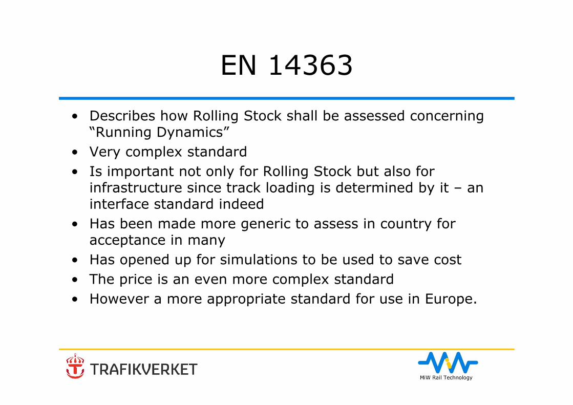
Origin
Axle load limitation
• 25 t for wagons• 22,5 t for locomotives and passenger
vehicles• A separate national standard
proposal was produced by Trafikverket and Jernbaneverket for use in Sweden and Norway (to be adopted and notified)
Challenge
• Create a standard that can be followed at reasonable cost
• Create a standard that can be used for acceptance in Europe (test in country A for acceptance in country B, C, …)
• Not increase but give possibilities to reduce acceptance cost
• Adaptation so it can be used in a TSI context (back-doors need to be created when a literal interpretation may cause problems)
• Maintain current level of safety
Title
• 2005: Testing for the acceptance of running characteristics of railway vehicles - Testing of running behavior and stationary tests
• 2016: Testing and Simulation for the acceptance of running characteristics of railway vehicles – Running Behaviour and stationary tests
Representation
• Austria, Czech republic, France, Germany, Italy, Norway, Sweden, Switzerland, Great Britain
• An interface standard, hence:• Railway Operators, Infrastructure managers,
Rolling stock suppliers, National standardisation bodies, Testing institutes
• The Swedish input to the standard was financed by Trafikverket. The work was lead in CEN TC256 / WG10 /SG8 by the Swedish representative.
WG10 / SG8 was divided into 8 sub-sub-groups
WG10/SG8 (Wrang, SE)WG10/SG8.1: Editorial group (Zeipel, DE)WG10/SG8.2: Test conditions (Wrang, SE)WG10/SG8.3: Track Quality & Contact conditions (Eickhoff, GB)WG10/SG8.5: Special Vehicles (yellow machines) (Dupont, FR)WG10/SG8.5: Stationary Tests (Carter, GB)WG10/SG8.6: Simulation, Extension of acceptance (Zeipel, DE)WG10/SG8.7: Track Loading (Stephanides, AT)WG10/SG8.8: Ride Characteristics (Stradtmann, DE)
Afterwards discussion was ongoing in WG 10 and in the enquiry process
The most important changes• Introduction of the multiple regression – allows for non-compliant test
conditions in reality reducing European homologation cost by making tests from different countries comparable.
• Introduction of simulations – may also reduce homologation costs• More thorough handling of equivalent conicity – facilitates cross border
traffic and reduces homologation costs• Removal of two rail inclination testing when the equivalent conicity is
known and compliant• Removal of or making “comfort” requirements informative. Adaptation to
TSI and hand over these questions to the vehicle buyers and suppliers to handle jointly
• Adopting freight wagons up to 25 t axle load and vehicles intended to run with high cant deficiency (tilting vehicles)
• Making operational parameters speed and cant deficiency free of choice• And much much more…• This presentation can only cover the most important fields
Scope
• Several clarifications, limitations, changes and modifications• Two notes explaining why vehicles can also be operated safely
outside the target test conditions. • A note clarifies that the methods of this standard may also be
applied to determine operating rules under infrastructure conditions that are more severe than the target test conditions.
• As the target test conditions for stability testing were changed with respect of the target conditions of the TEN (Trans European Network), it was necessary to clarify, that the equivalent conicity to be included in the stability assessment might be higher in some national systems for the time being before the infrastructure target conditions are met.

Scope –The allowances
• Allowed to deviate from the rules laid down if evidence can be furnished that safety is at least the equivalent to that ensured by complying with these rules (moved to separate chapter)
• extremely important allowance in a world of TSIs. Everyone struggling with following the letter should look for these deviations possibilities in the ENs.
Fault Modes
• Many different praxis has evolved in various countries, so new definitions were needed as well as a general update.
• The explicit requirement on testing with deflated air springs was removed.
• A new section 5.2.2 “Fault modes” and a new chapter in Annex T (Simulation of on-track tests), T.2.5 (Investigation of dynamic behaviour in case of fault modes) was introduced.
• Over speed and over cant deficiency do not need to be assessed, neither shall to independent fault mode be simultaneously assessed.
• This gives for a more “open” risk based approach.• The intention is to provide a framework to assess the relevant
fault modes which may not be the same for each and every vehicle type, not to introduce additional assessment.
Newly specified tests• Safety against derailment under longitudinal compressive
forces in S-shaped curves , introduction of method in UIC leaflet 530-2 (now EN 15939).
• Evaluation of the torsional coefficient of a car body used for profile calculations
• Some countries require testing in switches. This was introduced as an informative annex
• Running safety in curved crossings for vehicles with small wheels, introduction of method in UIC 510-2
*tc
Statistical analysis and multiple regression
• For the assessment of on-track test results EN 14363 uses a statistical approach.
• Tests (or simulations) are done on a small part of the future field of application and statistical methods are applied in order to estimate or predict the highest future values of the assessment quantities.
• These estimated maximum values are compared to the limit values.
• The introduction of multiple regression allows for predicting the results on target values that were not fully tested and facilitates for acceptance in country B when tested in country A and can also contribute to closing an Open Point in the TSI.
• Results from DynoTrain used
Statistical analysis and multiple regression
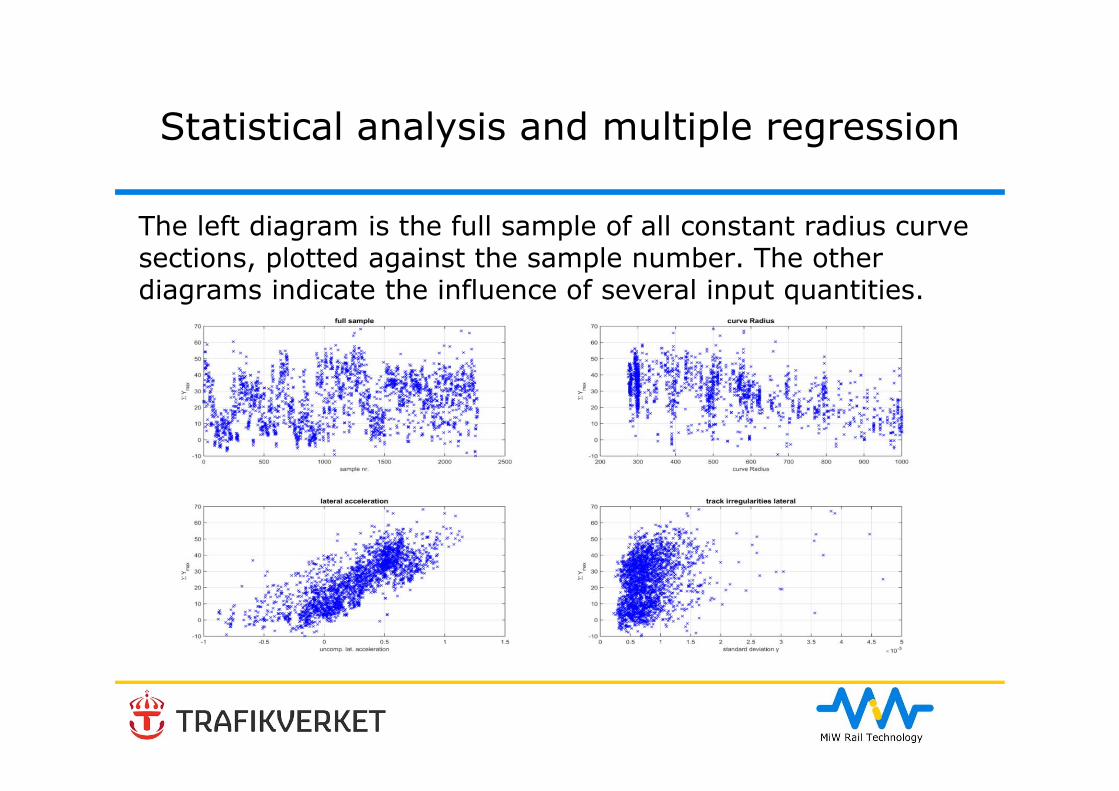
The left diagram is the full sample of all constant radius curve sections, plotted against the sample number. The other diagrams indicate the influence of several input quantities.
In EN 14363:2005 two statistical methods are mentioned:• one-dimensional method• two dimensional method (or simple regression)• In the new version additionally the multiple regression
method has been introduced.• Mathematically spoken, all three methods are regression
methods, where the data are modelled using no input parameter (one-dimensional method), one input parameter (two-dimensional method with cant deficiency as input parameter) or more input parameters (multiple regression).
Assessment by statistical methods in EN 14363
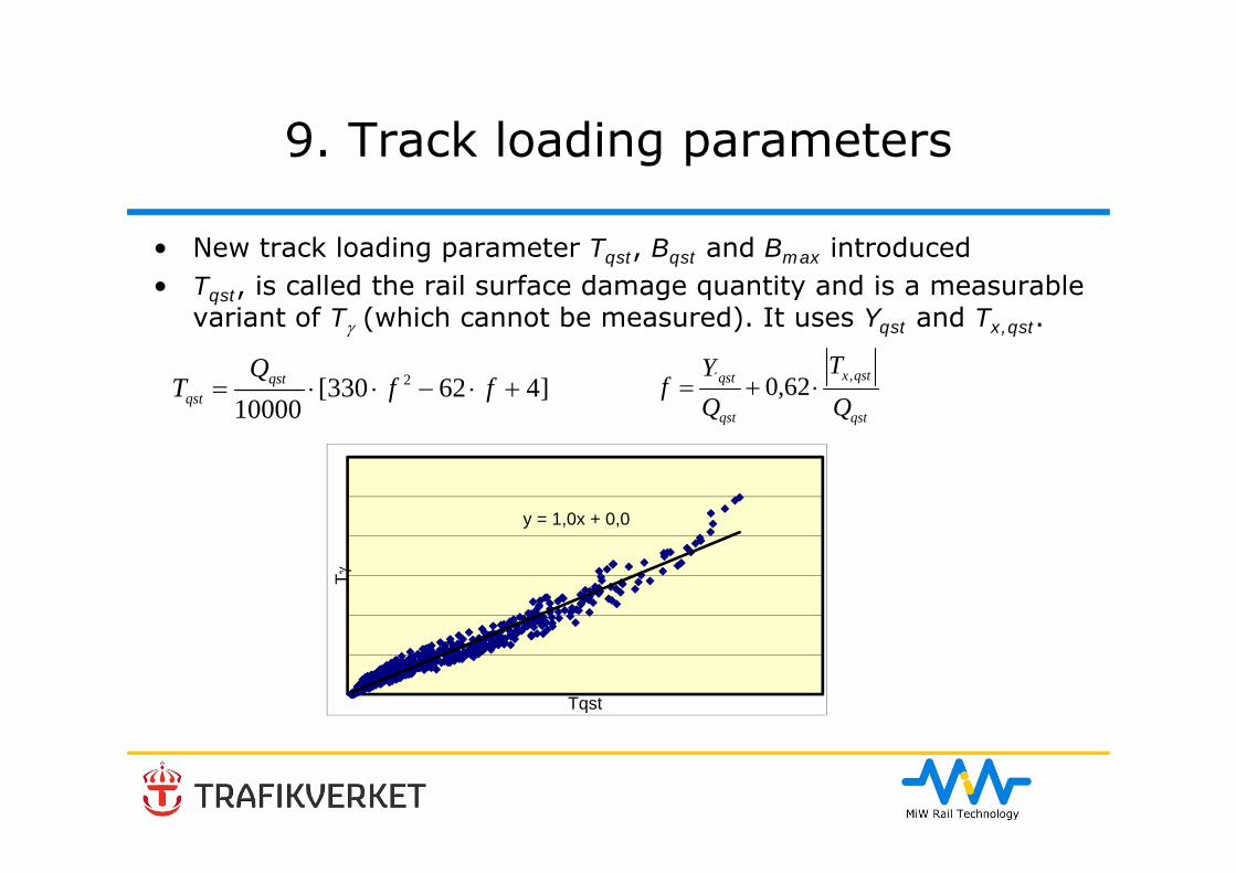
9. Track loading parameters
• New track loading parameter Tqst, Bqst and Bmax introduced• Tqst, is called the rail surface damage quantity and is a measurable
variant of T (which cannot be measured). It uses Yqst and Tx,qst.
]462330[10000
2 ffQ
T qstqst
qst
qstx
qst
qst
QT
QY
f ,´ 62,0
y = 1,0x + 0,0
T
Tqst
Replacing of limit values of ride characteristics by informative guidance for assessment
• Everything normative not related to safety or track loading removed
• All ride characteristics limit values removed and replaced with informative guidance
• Strenghth – WG2• Comfort – WG7 (EN 12299)• TSI does not cover comfort values• Also limit value for quasi-static lateral acceleration removed
– controlled with operational rules in combination with loading gauge control
• Puts higher demands on specification work for RST buyers
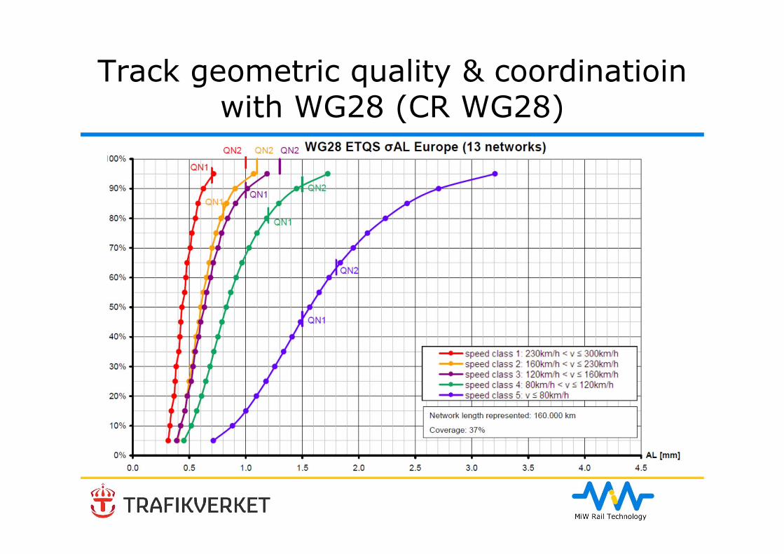
Track geometric quality & coordinatioin with WG28
• QN1, QN2 and QN3 removed and replaced with TL values• Using standard deviation kept – found to be the most
representative• The 90% value of the distribution shall be within the TL90
(70%-90% of European Networks) range if the one- or bi-dimension mathod is used
• The target value of the distribution shall be TL50 if the multiple regression is used
• This is an adaptation to existing track qualities in Europé• Helps in closing an Open Point in the RST TSIs
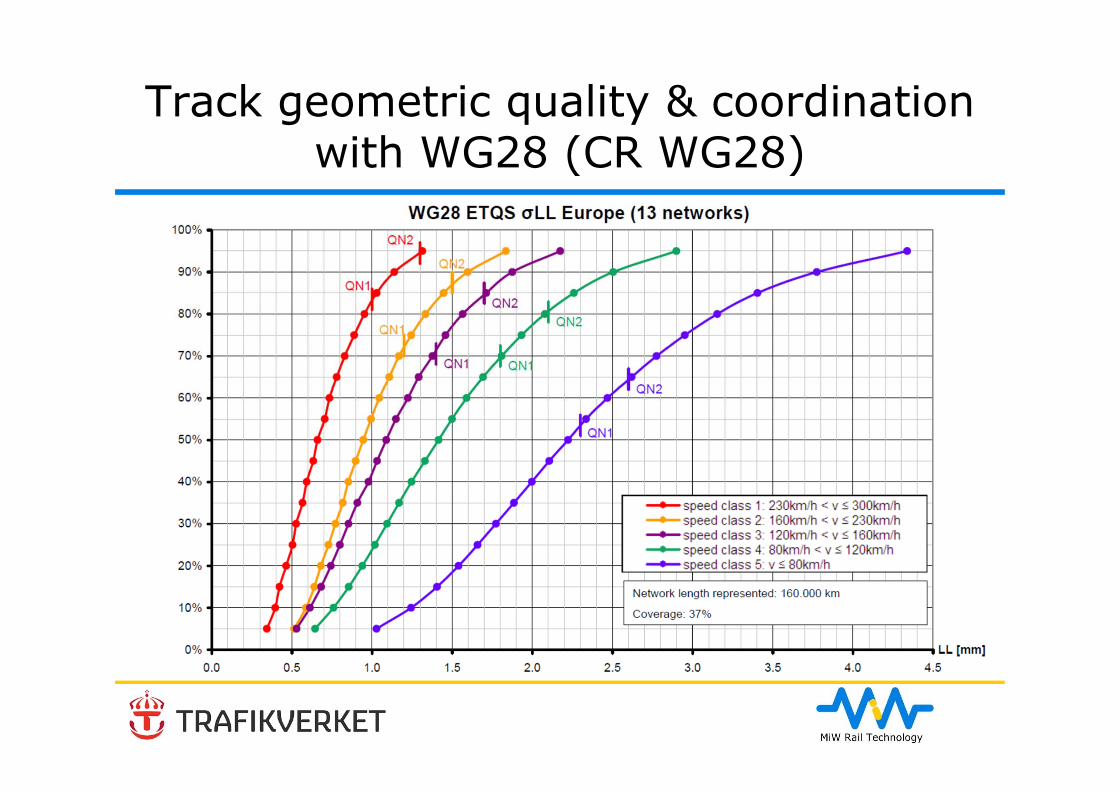
Track geometric quality & coordinationwith WG28 (CR WG28)
Track geometric quality & coordinatioin with WG28 (CR WG28)
Track geometric quality - Wavelength Ranges
• It is now recognised that the wavelength range D1 (3 m to 25 m) is not sufficient to cover the required inputs, particularly at higher speeds.
• No mandatory values are set for track geometry in wavelength range D2 or D3, as this data is not yet available from most networks.
• However for a reference speed > 160 km/h it is required to report the values for range D2 and for Speeds > 230 km/h
• It is recommended to also report the values from D3.

Contact Conditions - EquivalentConicity
Previously in EN14363:2005• Generally evaluated at y = ±3 mm.• For vehicles intended for unrestricted international
operation the test condition shall cover rail inclination of 1:20 and 1:40.
EN 14363:2016:• Still possible to test on two inclinations if no information on
equivalent conicity is available
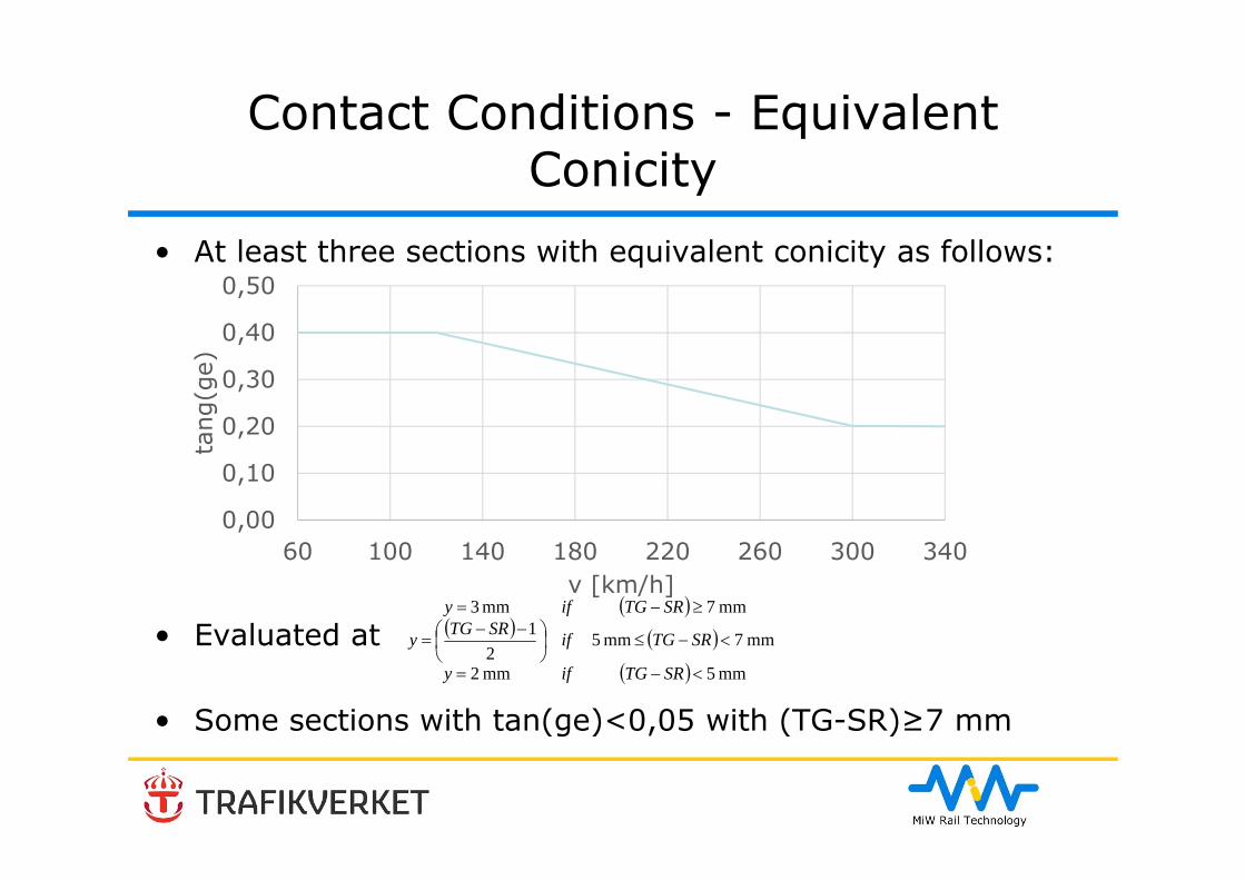
Contact Conditions - EquivalentConicity
• At least three sections with equivalent conicity as follows:
• Evaluated at
• Some sections with tan(ge)<0,05 with (TG-SR)≥7 mm
0,00
0,10
0,20
0,30
0,40
0,50
60 100 140 180 220 260 300 340
tang
(ge)
v [km/h]
mm 5mm 2
mm 7 mm 52
1mm 7mm 3
SRTGify
SRTGifSRTGy
SRTGify
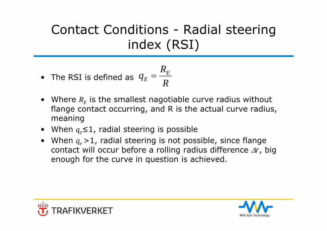
Contact Conditions - Radial steering index (RSI)
• The RSI is defined as
• Where RE is the smallest nagotiable curve radius withoutflange contact occurring, and R is the actual curve radius, meaning
• When qe≤1, radial steering is possible• When qe >1, radial steering is not possible, since flange
contact will occur before a rolling radius difference r, bigenough for the curve in question is achieved.
RRq E
E
Contact Conditions - Radial steering index (RSI)
• There are no requirements in EN 14363:2005 regarding the RSI.
• The RSI was introduced in UIC Leaflet 518:2009 in order to assess the steering capability in small radius curves. UIC Leaflet 518:2009 states that for low radius curves (250 m ≤ R ≤ 600 m) the RSI shall be ≥ 1 for 30% of the track sections and < 1 for 30% of the track sections.
• For EN 14363:2016, The RSI is in an informative Annex Q introduced in this version. No requirements on the RSI are specified.
The possibility to use simulations
The main input documents of the simulation annex were UIC 518:2009 and drafts of EN 15827 ("PTA Bogie"). Those inputs were extensively discussed, so that the Annex T “Simulations” reflects the experience of the experts of SG8.6 of WG10, who were responsible for this annex. Furthermore, inputs from the DynoTRAINproject were included during the finalisation of this annex.The following topics were identified for the evaluation in SG8.6 of WG10:• 01 Model validation• 02 Description of fields of application• 03 Specification of track data measurement• 04 Track data for simulation• 05 Implementation of simulations of stationary tests• 06 Process of application of simulation.
Principle of model validation
• The group members agreed with the conclusion used during the preparation of UIC 518:2009; that it is not necessary to undertake validation or benchmarking of the computer software.
• According to the opinion of some group members, the validation method described in UIC 518:2009 is too complex, costly and too difficult to fulfil.
• The group agreed that the model validation should be based on comparison of measurement with simulation using actual measured track irregularities.

The validation as described in UIC 518:2009 should cover:• comparison with static, laboratory and slow speed tests
where applicable,• frequency responses and PSDs from on-track tests,• time history responses from on-track tests,• analysis following the UIC518 procedure.
Evaluations to carry out model validation
• The quantitative validation criteria and limits for the maximum deviation between simulation and measurement were discussed and limits were proposed for the stationary test as well as for the on-track test (Table T.1). The values given for wheel loads and load distribution are taken from experience in UK as already used in UIC 518:2009. Regarding the on-track test, SG8.6 agreed on the proposed limits for the validation of Ya, qst and Qa, qst, but no limits could be agreed for other quantities.
• The model validation process is shown in Table T.1 • There are rules laid out for allowed model modifications
without the need for a re-validation
Evaluations to carry out model validation
During the development of UIC 518:2009, a use of an independent review of the comparison between the results from tests and simulations was agreed as the most appropriate method. This topic was extensively discussed during the preparation of EN 14363 revision. Another argument against the independent review was a possible subjectivity of the assessment result due to the expert's knowledge and experience performing the independent review is not specified. Based on this discussion, the requirements on the independent reviewer as well as the process of the assessment and on the documentation of the independent review were described in more detail. Additionally a flow chart illustrating the process was added (Figure T.1).
Independent review
Fields and conditions for application of simulation
The areas for the application of numerical simulation are as follows:• Approval of vehicles following modifications• Approval of new vehicles by comparison with an already approved
vehicle (base design)• Supplement the range of test conditions when the full range of
conditions has not been covered (e.g. full range of curve radii, speeds, cant deficiency etc).
• Investigation of dynamic behaviour in case of faults

Example of simulation project
• The Swedish ATC system is sometimes designed for category A, B and S vehicles where the very common category A vehicle is for an allowed cant deficiency of 150 mm
• Due to decisions taken many years ago a vehicle with Vadm=200 km/h and Iadm=150 mm cannot always be utilised to its full potential on straight lines
• MiW has been given the task to use simulations to get acceptance in accordance with EN 14363:2016 in increasing the allowed cant deficiency for X74 (MTR Express Stadler Flirt used on the line Stockholm-Göteborg)

Example of simulation project
MTR Express X74 – MiW uses simulations in accordance with EN 14363 in order to reduce travel time between Stockholm and Göteborg
Some of the many topics discussed but was postponed for future revisions
• Y/Q was proposed to correct the individual values on sections where high frictionis is observed. This comment was not accepted, as no target value for friciton can be agreed for a safety related quantity for this revision.
• The rail surface damage quantity Tqst is introduced in section 7.5.3. Limited experience from using Tqst exists no limit values were introduced. Though it would have been possible to use the limit value for Yqst and derive an equivalent limit for Tqst, this approach was considered too risky.
• The combined rail loading quantity Bqst and Bmax are introduced in section 7.5.3. For the same reason as for Tqst no limit values were introduced.
• The maximum guiding force Ya,max is introduced in section 7.5.3. For the same reason as for Tqst no limit values were introduced.
• The high frequency contributions of the vertical wheel forces (Q) are primarily important for the superstructure of the track (and also for wheels, bearings and axles of the vehicle).
• In this context higher frequencies are those in the range of 20-200 Hz
• A simulation study was carried out to identify the influencing factors on the high frequency Q forces and a possible idea for how to evaluate the Q forces incorporating the high frequency parts was presented.
• More studies are needed before a firm proposal can be made.• In the upcoming revision of EN 14363 it will be discussed whether
or not high frequency Q forces will be part of it.
Some of the many topics discussed but waspostponed for future revisions
• ‘Cyclic Top’ describes a particular type of track geometry with a sequence of vertical track irregularities where each individual feature (usually a dip in the track top) is within the allowable limits but the cyclic nature of the input can lead to resonant behaviour and derailment.
• This type of track defect is very difficult to detect without specific criteria and is not easy to observe.
• Further work is needed to consider how assessment of this risk can practically be incorporated into European vehicle approval processes
Some of the many topics discussed but waspostponed for future revisions
• The tendency is that it is becoming more difficult to get permit to test at over-speed or excess cant deficiency.
• This was briefly discussed and led to a reduction of the required over-speed for HS vehicles.
• Will need more consideration for future revisions.
Some of the many topics discussed but waspostponed for future revisions
• This presentation can only skim the surface of this standard• Many modifications – refer to the CEN technical report EN
14363:2016 – yet to be published• The most important single introductions:
– Multiple regression– Use of simulations
A large and very detailed standard

Thankyou!Questions and/or comments?
![28C-6e-20150629112650 - Heritage Western Cape 14363, Lodge Lane... · idesign@easylink.co.za From: Sent: To: Subject: Attachments: Beste Komiteelede Zenobia Ayford [Zenobia.Ayford@drakenstein.gov.za]](https://img.pdfslide.us/doc/110x75/5a936b937f8b9a30358bc54f/28c-6e-20150629112650-heritage-western-14363-lodge-laneidesigneasylinkcoza.jpg)