Embed Size (px)
Citation preview

A product of SEGGER Microcontroller GmbH & Co. KG
emModbus
Document: UM14001Software version: 1.00
Revision: 2Date: July 1, 2014
User & Reference Guide
CPU independentModbus stack for
embedded applications
www.segger.com
2
Disclaimer
Specifications written in this document are believed to be accurate, but are not guar-anteed to be entirely free of error. The information in this manual is subject tochange for functional or performance improvements without notice. Please make sureyour manual is the latest edition. While the information herein is assumed to beaccurate, SEGGER Microcontroller GmbH & Co. KG (SEGGER) assumes no responsibil-ity for any errors or omissions. SEGGER makes and you receive no warranties or con-ditions, express, implied, statutory or in any communication with you. SEGGERspecifically disclaims any implied warranty of merchantability or fitness for a particu-lar purpose.
Copyright notice
You may not extract portions of this manual or modify the PDF file in any way withoutthe prior written permission of SEGGER. The software described in this document isfurnished under a license and may only be used or copied in accordance with theterms of such a license.
© 2014 SEGGER Microcontroller GmbH & Co. KG, Hilden / Germany
Trademarks
Names mentioned in this manual may be trademarks of their respective companies.
Brand and product names are trademarks or registered trademarks of their respec-tive holders.
Contact address
SEGGER Microcontroller GmbH & Co. KG
In den Weiden 11D-40721 Hilden
Germany
Tel.+49 2103-2878-0Fax.+49 2103-2878-28E-mail: [email protected]: http://www.segger.com
UM14001 User & Reference Guide for emModbus © 2014 SEGGER Microcontroller GmbH & Co. KG
3
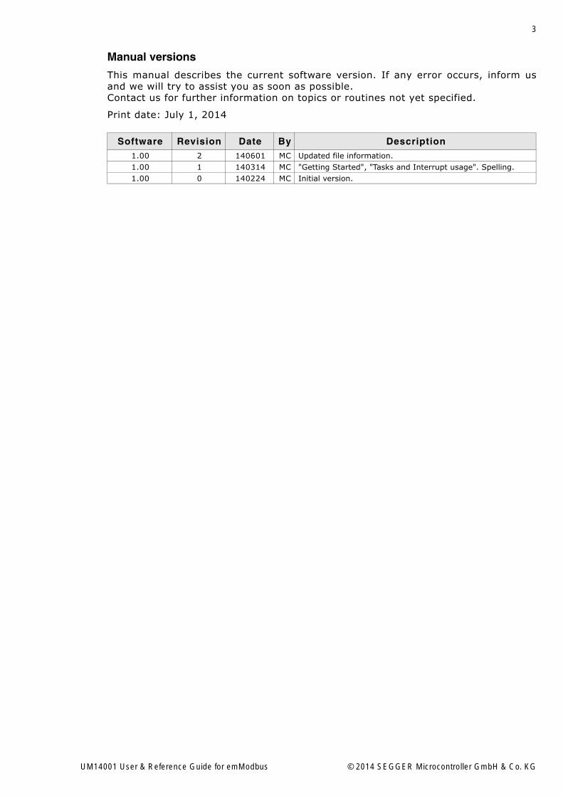
Manual versions
This manual describes the current software version. If any error occurs, inform usand we will try to assist you as soon as possible.Contact us for further information on topics or routines not yet specified.
Print date: July 1, 2014
Software Revision Date By Description1.00 2 140601 MC Updated file information.1.00 1 140314 MC "Getting Started", "Tasks and Interrupt usage". Spelling.1.00 0 140224 MC Initial version.
UM14001 User & Reference Guide for emModbus © 2014 SEGGER Microcontroller GmbH & Co. KG

4
UM14001 User & Reference Guide for emModbus © 2014 SEGGER Microcontroller GmbH & Co. KG

5
About this documentAssumptions
This document assumes that you already have a solid knowledge of the following:
� The software tools used for building your application (assembler, linker, C com-piler)
� The C programming language� The target processor� DOS command line
If you feel that your knowledge of C is not sufficient, we recommend The C Program-ming Language by Kernighan and Richie (ISBN 0-13-1103628), which describes thestandard in C-programming and, in newer editions, also covers the ANSI C standard.
How to use this manualThis manual explains all the functions and macros that the product offers. It assumesyou have a working knowledge of the C language. Knowledge of assembly program-ming is not required.
Typographic conventions for syntax
This manual uses the following typographic conventions:
Style Used for
Body Body text.
KeywordText that you enter at the command-prompt or that appears on the display (that is system functions, file- or pathnames).
Parameter Parameters in API functions.
Sample Sample code in program examples.
Sample comment Comments in programm examples.
Reference Reference to chapters, sections, tables and figures or other docu-ments.
GUIElement Buttons, dialog boxes, menu names, menu commands.
Emphasis Very important sections.
Table 1.1: Typographic conventions
UM14001 User & Reference Guide for emModbus © 2014 SEGGER SEGGER Microcontroller GmbH & Co. KG

6
EMBEDDED SOFTWARE(Middleware)
emWinGraphics software and GUIemWin is designed to provide an effi-cient, processor- and display control-ler-independent graphical user interface (GUI) for any application that operates with a graphical display.
embOSReal Time Operating SystemembOS is an RTOS designed to offer the benefits of a complete multitasking system for hard real time applications with minimal resources.
embOS/IPTCP/IP stackembOS/IP a high-performance TCP/IP stack that has been optimized for speed, versatility and a small memory footprint.
emFileFile systememFile is an embedded file system with FAT12, FAT16 and FAT32 support. Vari-ous Device drivers, e.g. for NAND and NOR flashes, SD/MMC and Compact-Flash cards, are available.
USB-StackUSB device/host stackA USB stack designed to work on any embedded system with a USB control-ler. Bulk communication and most stan-dard device classes are supported.
SEGGER TOOLS
Flasher Flash programmerFlash Programming tool primarily for micro con-trollers.
J-LinkJTAG emulator for ARM coresUSB driven JTAG interface for ARM cores.
J-TraceJTAG emulator with traceUSB driven JTAG interface for ARM cores with Trace memory. supporting the ARM ETM (Embed-ded Trace Macrocell).
J-Link / J-Trace Related SoftwareAdd-on software to be used with SEGGER�s indus-try standard JTAG emulator, this includes flash programming software and flash breakpoints.
SEGGER Microcontroller GmbH & Co. KG developsand distributes software development tools and ANSI Csoftware components (middleware) for embedded sys-tems in several industries such as telecom, medicaltechnology, consumer electronics, automotive industryand industrial automation.
SEGGER�s intention is to cut software development timefor embedded applications by offering compact flexible and easy to use middleware,allowing developers to concentrate on their application.
Our most popular products are emWin, a universal graphic software package for embed-ded applications, and embOS, a small yet efficient real-time kernel. emWin, writtenentirely in ANSI C, can easily be used on any CPU and most any display. It is comple-mented by the available PC tools: Bitmap Converter, Font Converter, Simulator andViewer. embOS supports most 8/16/32-bit CPUs. Its small memory footprint makes itsuitable for single-chip applications.
Apart from its main focus on software tools, SEGGER develops and produces programmingtools for flash micro controllers, as well as J-Link, a JTAG emulator to assist in develop-ment, debugging and production, which has rapidly become the industry standard fordebug access to ARM cores.
Corporate Office:http://www.segger.com
United States Office:http://www.segger-us.com
UM14001 User & Reference Guide for emModbus © 2014 SEGGER Microcontroller GmbH & Co. KG
7
Table of Contents
1 Introduction to emModbus ...............................................................................................9
1.1 The Modbus standard ...............................................................................101.2 emModbus..............................................................................................141.3 Tasks and interrupt usage.........................................................................16
2 Getting Started...............................................................................................................21
2.1 Installation .............................................................................................222.2 Upgrade a trial version .............................................................................232.3 Upgrade an embOS start project................................................................242.4 Create a project from scratch ....................................................................29
3 Example applications .....................................................................................................31
3.1 Overview................................................................................................32
4 Core functions................................................................................................................35
4.1 API functions ..........................................................................................364.2 emModbus data structures........................................................................644.3 Error codes.............................................................................................69
5 Configuring emModbus..................................................................................................71
5.1 Compile-time configuration .......................................................................72
6 Debugging......................................................................................................................75
6.1 Message output.......................................................................................766.2 Using a network sniffer to analyse ethernet communication problems .............816.3 Testing emModbus applications .................................................................82
7 OS Integration................................................................................................................83
7.1 General information .................................................................................847.2 OS layer API functions..............................................................................85
8 Resource usage.............................................................................................................97
8.1 Memory footprint.....................................................................................98
UM14001 User & Reference Guide for emModbus © 2014 SEGGER Microcontroller GmbH & Co. KG

8
UM14001 User & Reference Guide for emModbus © 2014 SEGGER Microcontroller GmbH & Co. KG

9
Chapter 1
Introduction to emModbus
This chapter provides an introduction to using emModbus. It explains the basic con-cepts behind emModbus.
UM14001 User & Reference Guide for emModbus © 2014 SEGGER Microcontroller GmbH & Co. KG

10 CHAPTER 1 Introduction to emModbus
1.1 The Modbus standardThe Modbus protocol was originally published in 1979 by Modicon (which laterbecame Schneider Electric) and has since evolved into a standard communicationsprotocol for industrial electronic devices. In 2004, Schneider transfered rights to theprotocol to the Modbus Organization, which since is in charge of the open standard�sfurther development.
1.1.1 Modbus message basicsThe modbus protocol is an application layer messaging protocol used for communica-tions between devices that are connected to different types of buses or networks.It uses a master-slave-technique in which one device, the master, initiates transac-tions (called �queries�). Other devices, the slaves, respond by performing the actionrequested in the query or by supplying the requested data to the master.The protocol determines how each device will know its address, how it will recognizea message addressed to it, how it will determine the kind of action to be taken andhow it will extract data or any other information contained in the message. It alsodetermines how slaves construct and send reply messages.
1.1.1.1 Message framesSeveral Modbus messaging formats ("frames") exist and are used for different pur-poses and environments, though many of them are not compliant to the Modbusstandard. The standard-compliant frame variants are listed in the following table:
When using ASCII frames or RTU frames via serial connection, parameters such asbaud rate and parity bits must be set correctly for all connected devices.When using Modbus/TCP, setting these parameters is not required, but correct IPaddress and port number are required instead. The standard port number for Mod-bus/TCP is port 502.
Protocol Description
RTUOriginal Modbus standard. Binary data is sent via serial connec-tions such as RS-232 or similar.
ASCII Similar to RTU. Instead of raw binary, data is encoded in ASCII.
Modbus/TCPBinary data is encapsulated in a TCP frame and sent via net-work connections such as Ethernet. This variant can also be used with UDP instead of TCP and is then called Modbus/UDP.
Table 1.1: Standard-compliant variants of Modbus message frames
UM14001 User & Reference Guide for emModbus © 2014 SEGGER Microcontroller GmbH & Co. KG

11
1.1.1.2 Message fieldsAlthough the different message frames are each handled differently by the protocol,RTU frames and ACSCII frames each include the same four fields. Field 2 and 3 con-stitute the Protocol Data Unit (PDU), which is part of Modbus/TCP message frames aswell, while all 4 fields together constitute the Application Data Unit (ADU):
Field 1 includes the address of a slave device, either indicating the slave that is des-ignated to receive the message from its master, or indicating the slave that sent themessage towards its master. This address, which is refered to as "unit ID" or "slaveaddress", is a number from 1 to 247 and is uniquely assigned to a single slavedevice, allowing these devices to listen for messages containing their specific ID.Additionaly, ID 0 is used to send broadcasts and ID 255 usually is reserved for com-munications with a Modbus gateway.
Field 2 includes a function code, which, when sent by a master, indicates the instruc-tion a slave is asked to carry out. When sent by a slave, on the other hand, the func-tion code indicates the instruction the slave is responding to.
Field 3 contains variable amounts of data, e.g. certain data addresses a master wantsa slave to read, or the data a slave is reporting towards its master.
In field 4 Modbus messages carry a checksum to allow their respective recipients todetermine wether a message has arrived completely.
RTU message frames
When using RTU frames, each byte contained in a message is sent as binary data.The main advantage of this mode is its greater density, allowing better data through-put for the same baud rate when compared to ASCII frames. To indicate the start ofan RTU frame, the ADU is preceded by a silent interval of at least 3.5 Byte times,hence the length of that interval depends on the configuration of the devices in use.To indicate the end of a frame, another silent interval of 3.5 Byte times succeeds theADU. Note that one single interval of silence can, at the same time, indicate the endof one frame and the beginning of another frame. RTU frames use Cyclic RedundancyChecks (CRC).A complete RTU frame can be depicted as shown below:
UM14001 User & Reference Guide for emModbus © 2014 SEGGER Microcontroller GmbH & Co. KG

12 CHAPTER 1 Introduction to emModbus
ASCII message frames
When using ASCII frames, each byte contained in a message is encoded and sent astwo ASCII characters. This allows time intervals of up to one second to occurbetween characters without causing an error. To indicate the start of a frame, theADU is preceded by a single character, which always is a colon (0x3A). To indicate theend of a frame, another two trailing characters succeed the ADU, which always are"Carriage Return" and "Line Feed" (0x0D and 0x0A, respectively). ASCII frames useLongitudinal Redundancy Checks (LRC).A complete ASCII frame can be depicted as shown below:
Modbus/TCP message frames
When using Modbus/TCP frames, an additional header called "Modbus ApplicationHeader" precedes the PDU. Its four fields contain the transaction ID, the protocol ID,the length of the following frame and the slave address.
The transaction ID is a number from 0 to 65,535 encoded into two bytes. A masterdevice will increment this number for every request it sends to a slave, while slavessimply echoe the number back to their master. By doing so, the master is able todecide wether messages got lost or delayed in transmission.
The protocol ID is a two-byte value, too, but is always 00 00. The length field con-sists of two more bytes indicating the length of the remaining message.
Finally the address field contains a unit ID, similar to that included in ASCII frames orRTU frames. But with Modbus/TCP, it does not necessarily serve a purpose, as the IPaddress is used instead to indicate the message�s recipient. However, the unit ID isstill part of the message and might be used to decide whether a device forwards amessage onto a serial connection, thereby allowing devices without networking capa-bilities to be used in these environments, too.
A complete Modbus/TCP frame can be depicted as shown below:
UM14001 User & Reference Guide for emModbus © 2014 SEGGER Microcontroller GmbH & Co. KG
13
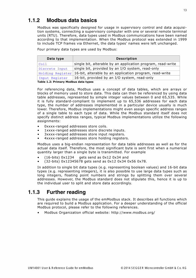
1.1.2 Modbus data basicsModbus was specifically designed for usage in supervisory control and data acquisi-tion systems, connecting a supervisory computer with one or several remote terminalunits (RTU). Therefore, data types used in Modbus communications have been namedaccording to that implementation. When the Modbus protocol was extended in 1999to include TCP frames via Ethernet, the data types� names were left unchanged.
Four primary data types are used by Modbus:
For referencing data, Modbus uses a concept of data tables, which are arrays orblocks of memory used to store data. This data can then be referenced by using datatable addresses, represented by simple integer values between 0 and 65,535. Whileit is fully standard-compliant to implement up to 65,536 addresses for each datatype, the number of addresses implemented in a particular device usually is muchlower. Therefore, Modbus implementations might even assign specific address rangesof a single table to each type of data. While the Modbus standard itself does notspecify distinct address ranges, typical Modbus implementations utilize the followingassignments:
� 0xxxx-ranged addresses store coils.� 1xxxx-ranged addresses store discrete inputs.� 3xxxx-ranged addresses store input registers.� 4xxxx-ranged addresses store holding registers.
Modbus uses a big-endian representation for data table addresses as well as for theactual data itself. Therefore, the most significant byte is sent first when a numericalquantity larger than a single byte is transmitted. For example
� (16-bits) 0x1234 gets send as 0x12 0x34 and� (32-bits) 0x12345678 gets send as 0x12 0x34 0x56 0x78.
In addition to single bit data types (e.g. representing boolean values) and 16-bit datatypes (e.g. representing integers), it is also possible to use large data types such aslong integers, floating point numbers and strings by splitting them over severaladdresses. However, the Modbus standard does not stipulate this, hence it is up tothe individual user to split and store data accordingly.
1.1.3 Further readingThis guide explains the usage of the emModbus stack. It describes all functions whichare required to build a Modbus application. For a deeper understanding of the officialModbus protocol, please refer to the following references.
� Modbus Organization official website: http://www.modbus.org/
Data type Description
Coil single bit, alterable by an application program, read-writeDiscrete Input single bit, provided by an I/O system, read-onlyHolding Register 16-bit, alterable by an application program, read-writeInput Register 16-bit, provided by an I/O system, read-only
Table 1.2: Primary Modbus data types
UM14001 User & Reference Guide for emModbus © 2014 SEGGER Microcontroller GmbH & Co. KG

14 CHAPTER 1 Introduction to emModbus
1.2 emModbusemModbus is written in ANSI C and can be used on virtually any CPU. It combines amaximum of performance with a small memory footprint and comes with all featurestypically required by embedded systems. RAM usage has been kept to a minimum bysmart buffer handling.
1.2.1 Features of emModbusFeatures of emModbus include:
� Easy to integrate.� Low memory footprint.� ANSI-C code is completely portable and runs on any target.� Follows the SEGGER coding standards: Efficient and compact, yet easy to read,
understand & debug. � Supports ASCII, RTU and Modbus/TCP (and UDP) protocol.� Sample applications for all protocols included.� Kernel abstraction layer: can be used with or without any RTOS.� Works out-of-the-box with embOS.� Modbus/TCP can be used with standard socket interface and any TCP/IP stack.� Works out-of-the-box with embOS/IP.� Project for executable on PC for Microsoft Visual Studio available.
The following table shows the contents of the emModbus root directory:
1.2.2 emModbus requirementsTCP/IP stack
For usage of Modbus/TCP, emModbus requires a TCP/IP capable stack. emModbus canbe used with any TCP/IP stack that supports BSD Standard Sockets. The shipmentincludes an implementation which uses the socket API of embOS/IP.
Multi tasking
Although emModbus can be used completely without an RTOS, it is recommended touse emModbus in a multi tasking system, at least when implementing a Modbus mas-ter.
Directory Content
Application\*.cContains example applications to run emModbus with UART or embOS/IP.
Config\*.*Contains the emModbus configuration files. Refer to Configuring emModbus on page 71 for further information.
MB\*.*Contains the emModbus sources such as MB_Core.c, MB_CHANNEL.c, MB_MASTER.c and MB_SLAVE.c
Util\*.cContains optimized memcpy routines to speed up the stack.
Windows\*.*Contains the source(s), project file(s) and a executable(s) to run emModbus on a Microsoft Windows host.
Table 1.3: Supplied directory structure of emModbus shippings
UM14001 User & Reference Guide for emModbus © 2014 SEGGER Microcontroller GmbH & Co. KG
15
1.2.3 Development environment (compiler)The CPU used is of no importance; only an ANSI-compliant compiler complying withat least one of the following international standard is required:
� ISO/IEC/ANSI 9899:1990 (C90) with support for C++ style comments (//)� ISO/IEC 9899:1999 (C99)� ISO/IEC 14882:1998 (C++)
If your compiler has some limitations, let us know and we will inform you if these willbe a problem when compiling the software. Any compiler for 16/32/64-bit CPUs orDSPs that we know of can be used; most 8-bit compilers can be used as well.
� A C++ compiler is not required, but can be used. The application program cantherefore also be programmed in C++ if desired.
UM14001 User & Reference Guide for emModbus © 2014 SEGGER Microcontroller GmbH & Co. KG
16 CHAPTER 1 Introduction to emModbus
1.3 Tasks and interrupt usageemModbus can be used in an application in two different ways.
� With tasks dedicated to the stack.� Without tasks dedicated to the stack.
The following chapters provide information on these ways for both ASCII and RTUframes as well as for Modbus/TCP (or UDP) frames.
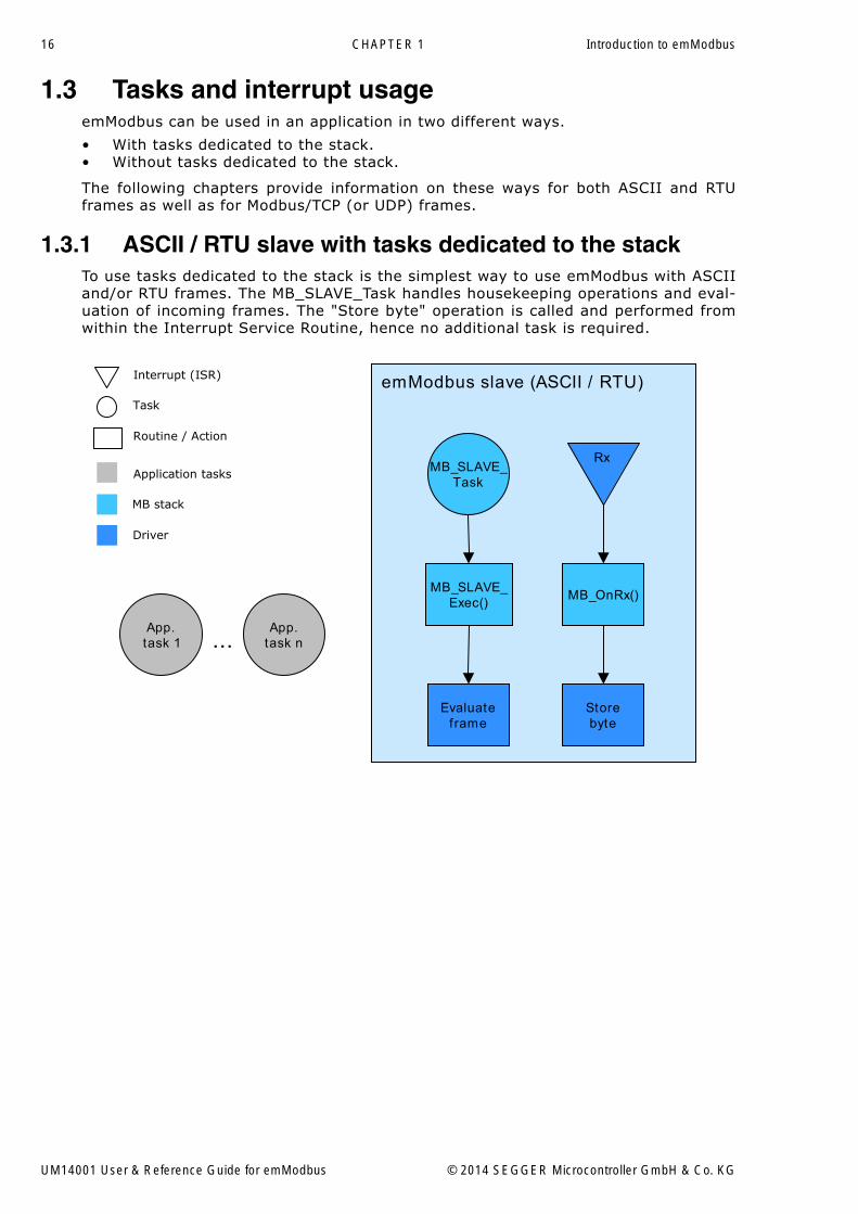
1.3.1 ASCII / RTU slave with tasks dedicated to the stackTo use tasks dedicated to the stack is the simplest way to use emModbus with ASCIIand/or RTU frames. The MB_SLAVE_Task handles housekeeping operations and eval-uation of incoming frames. The "Store byte" operation is called and performed fromwithin the Interrupt Service Routine, hence no additional task is required.
...
Task
Routine / Action
Interrupt (ISR) emModbus slave (ASCII / RTU)
MB_SLAVE_Exec()
Evaluateframe
MB_OnRx()
MB_SLAVE_Task
App.task n
App.task 1
Rx
MB stack
Driver
Application tasks
Storebyte
UM14001 User & Reference Guide for emModbus © 2014 SEGGER Microcontroller GmbH & Co. KG
17
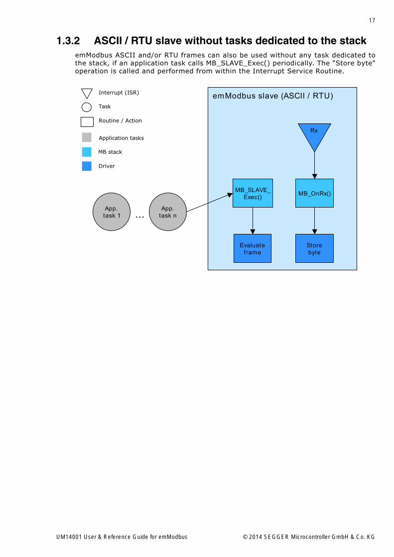
1.3.2 ASCII / RTU slave without tasks dedicated to the stackemModbus ASCII and/or RTU frames can also be used without any task dedicated tothe stack, if an application task calls MB_SLAVE_Exec() periodically. The "Store byte"operation is called and performed from within the Interrupt Service Routine.
...
Task
Routine / Action
Interrupt (ISR) emModbus slave (ASCII / RTU)
App.task n
App.task 1
MB stack
Driver
Application tasks
MB_SLAVE_Exec()
Evaluateframe
MB_OnRx()
Rx
Storebyte
UM14001 User & Reference Guide for emModbus © 2014 SEGGER Microcontroller GmbH & Co. KG

18 CHAPTER 1 Introduction to emModbus
1.3.3 TCP / UDP slave with tasks dedicated to the stackTo use tasks dedicated to the stack is the simplest way to use emModbus/TCP. TheMB_SLAVE_Task handles housekeeping operations and evaluation of incomingframes. The "Read frame" operation is called and performed by another task,MB_SLAVE_PollChannel, which periodically polls for incoming frames.
...
Task
Routine / Action
Interrupt (ISR) emModbus slave (TCP / UDP)
Readframe
App.task n
App.task 1
MB stack
Driver
Application tasks MB_SLAVE_PollChannel
MB_SLAVE_Exec()
Evaluateframe
MB_SLAVE_Task
UM14001 User & Reference Guide for emModbus © 2014 SEGGER Microcontroller GmbH & Co. KG

19
1.3.4 TCP / UDP slave without tasks dedicated to the stackemModbus/TCP can also be used without any task dedicated to the stack, if an appli-cation task consecutively calls MB_SLAVE_PollChannel() and MB_SLAVE_Exec() peri-odically.
...
Task
Routine / Action
Interrupt (ISR) emModbus slave (TCP / UDP)
App.task n
App.task 1
MB stack
Driver
Application tasksMB_SLAVE_
PollChannel()
MB_SLAVE_Exec()
Evaluateframe
Readframe
1.)
2.)
UM14001 User & Reference Guide for emModbus © 2014 SEGGER Microcontroller GmbH & Co. KG
20 CHAPTER 1 Introduction to emModbus
1.3.5 emModbus masterThe emModbus master API is independent of the usage of any Real-time operatingsystem. However, by utilizing an RTOS the emModbus interface becomes more easyand comfortable to integrate into any desired application.
UM14001 User & Reference Guide for emModbus © 2014 SEGGER Microcontroller GmbH & Co. KG
21
Chapter 2
Getting Started
The first step in getting started with emModbus is to compile it for and run it on thetarget system. This chapter explains how to do this.
In this document the IAR Embedded Workbench® IDE is used for all examples andscreenshots, but every other ANSI C toolchain can be used as well. It is also possibleto use makefiles; in this case, �add to the project� translates into �add to the make-file�.
UM14001 User & Reference Guide for emModbus © 2014 SEGGER Microcontroller GmbH & Co. KG

22 CHAPTER 2 Getting Started
2.1 InstallationemModbus is typically shipped as a .zip file in electronic form. In order to installemModbus, extract it to any folder of your choice, preserving the directory structureof the .zip file.
To create a running emModbus project, there are 3 different ways available:
� Upgrade a trial version by adding source code.� Upgrade an embOS start project.� Create a project from scratch.
The following example procedures describe each of these ways. They focus on inte-grating an emModbus slave device using Modbus/TCP frames, but any other emMod-bus project can be created as well by following the same steps.
emModbus via TCP is optimized to be used with embOS/IP, SEGGER�s TCP/IP stack.However, emModbus can be used with any other TCP/IP stack as well. Note that whenusing ASCII frames or RTU frames, the integration of a TCP/IP stack is not requiredand should be omitted for smaller code size. Similarly, if no real-time operating sys-tem is required, the integration of an RTOS should be omitted as well.
UM14001 User & Reference Guide for emModbus © 2014 SEGGER Microcontroller GmbH & Co. KG
23
2.2 Upgrade a trial versionVarious trial packages for different target hardware are available at SEGGER�s web-site.
Note that not all trial packages currently available contain a trial of emModbus. If youare interested in a specific package that does not contain emModbus yet, feel free tocontact us. Including emModbus in a trial package can be done in short time. Addi-tionally, trial packages that do not contain embOS/IP do lack an appropiate TCP/IPstack, which is required for Modbus/TCP frames. However, ASCII frames and RTUframes might be used regardless of a TCP/IP stack.
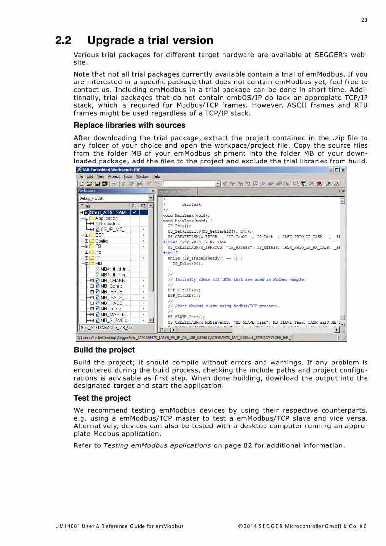
Replace libraries with sources
After downloading the trial package, extract the project contained in the .zip file toany folder of your choice and open the workpace/project file. Copy the source filesfrom the folder MB of your emModbus shipment into the folder MB of your down-loaded package, add the files to the project and exclude the trial libraries from build.
Build the project
Build the project; it should compile without errors and warnings. If any problem isencoutered during the build process, checking the include paths and project configu-rations is advisable as first step. When done building, download the output into thedesignated target and start the application.
Test the project
We recommend testing emModbus devices by using their respective counterparts,e.g. using a emModbus/TCP master to test a emModbus/TCP slave and vice versa.Alternatively, devices can also be tested with a desktop computer running an appro-piate Modbus application.
Refer to Testing emModbus applications on page 82 for additional information.
UM14001 User & Reference Guide for emModbus © 2014 SEGGER Microcontroller GmbH & Co. KG

24 CHAPTER 2 Getting Started
2.3 Upgrade an embOS start projectBegin with a sample project for embOS, SEGGER�s real-time operating system, theninclude embOS/IP and emModbus into the project.
The emModbus default configuration is preconfigured with valid values, which matchthe requirements of most applications.
Procedure to follow
Integration of emModbus is a relatively simple process, which consists of the follow-ing steps:
� Step 1: Open an embOS start project.� Step 2: Add embOS/IP to the start project.� Step 3: Add emModbus to the start project.� Step 4: Build the project.
UM14001 User & Reference Guide for emModbus © 2014 SEGGER Microcontroller GmbH & Co. KG

25
2.3.1 Step 1: Open an embOS start projectWe recommend that you use one of the supplied embOS start projects for your targetsystem. Compile the project and run it on your target hardware.
UM14001 User & Reference Guide for emModbus © 2014 SEGGER Microcontroller GmbH & Co. KG

26 CHAPTER 2 Getting Started
2.3.2 Step 2: Adding embOS/IP to the start projectAdd all source files in the following directories to your project:
• Config• IP• UTIL (optional)
The Config folder includes all configuration files of embOS/IP. The configuration filesare preconfigured with valid values that match the requirements of most applica-tions. Add the hardware configuration IP_Config_<TargetName>.c supplied with thedriver shipment.
If your hardware is currently not supported, use the example configuration file andthe driver template to write your own driver. The example configuration file and thedriver template is located in the Sample\Driver\Template folder.
The Util folder is an optional component of the embOS/IP shipment. It containsoptimized MCU and/or compiler specific files, for example an optimized memcopyfunction.
Replace BSP.c and BSP.h of your embOS start project
Replace the BSP.c source file and the BSP.h header file used in your embOS startproject with the one which is supplied with the embOS/IP shipment. Some driversrequire a special functions which initializes the network interface of the driver. Thisfunction is called BSP_ETH_Init(). It is used to enable the ports which are connectedto the network hardware. All network interface driver packages include the BSP.cand BSP.h files irrespective if the BSP_ETH_Init() function is implemented.
Configuring the include path
The include path is the path in which the compiler looks for include files. In caseswhere the included files (typically header files, .h) do not reside in the same direc-tory as the C file to compile, an include path needs to be set. In order to build theproject with all added files, you will need to add the following directories to yourinclude path:
• Config• Inc• IP
UM14001 User & Reference Guide for emModbus © 2014 SEGGER Microcontroller GmbH & Co. KG

27
2.3.3 Step 3: Adding emModbus to the start projectAdd all source files in the following directories to your project:
• Config• MB• UTIL (optional)
The Config folder includes all configuration files of emModbus. The configuration filesare preconfigured with valid values, which match the requirements of most applica-tions.
Configuring the include path
The include path is the path in which the compiler looks for include files. In caseswhere the included files (typically header files, .h) do not reside in the same direc-tory as the C file to compile, an include path needs to be set. In order to build theproject with all added files, you will need to add the following directories to yourinclude path:
• Config• MB
Select the start application
For quick and easy testing of your emModbus integration, start with the code foundin the folder Application. Add one of the applications to your project (for exampleOS_IP_MB_SlaveTCP.c).
UM14001 User & Reference Guide for emModbus © 2014 SEGGER Microcontroller GmbH & Co. KG

28 CHAPTER 2 Getting Started
2.3.4 Step 4: Build the project Build the project
Build the project; it should compile without errors and warnings. If any problem isencoutered during the build process, checking the include paths and project configu-rations is advisable as first step. When done building, download the output into thedesignated target and start the application.
Test the project
We recommend testing emModbus devices by using their respective counterparts,e.g. using a emModbus/TCP master to test a emModbus/TCP slave and vice versa.Alternatively, devices can also be tested with a desktop computer running an appro-piate Modbus application.
Refer to Testing emModbus applications on page 82 for additional information.
UM14001 User & Reference Guide for emModbus © 2014 SEGGER Microcontroller GmbH & Co. KG

29
2.4 Create a project from scratchTo create a project from scratch, some steps have to be taken:
� A project or make file has to be created for the specific toolchain.� The project configurations may need adjustments.� The hardware routines have to be implemented.� The path of any required header files has to be set as include path.
To get the target up and running is a lot easier if taget hardware drivers are alreadyavailable. In that case, these drivers can be used.
Creating the project or make file
The screenshot below gives an idea about a possible project setup:
Build the project
Build the project; it should compile without errors and warnings. If any problem isencoutered during the build process, checking the include paths and project configu-rations is advisable as first step. When done building, download the output into thedesignated target and start the application.
Test the project
We recommend testing emModbus devices by using their respective counterparts,e.g. using a emModbus/TCP master to test a emModbus/TCP slave and vice versa.Alternatively, devices can also be tested with a desktop computer running an appro-piate Modbus application.
Refer to Testing emModbus applications on page 82 for additional information.
UM14001 User & Reference Guide for emModbus © 2014 SEGGER Microcontroller GmbH & Co. KG

30 CHAPTER 2 Getting Started
UM14001 User & Reference Guide for emModbus © 2014 SEGGER Microcontroller GmbH & Co. KG
31
Chapter 3
Example applications
In this chapter, you will find a description of the emModbus example applications thatare delivered together with the emModbus shipment.
UM14001 User & Reference Guide for emModbus © 2014 SEGGER Microcontroller GmbH & Co. KG

32 CHAPTER 3 Example applications
3.1 OverviewExample applications for emModbus are supplied in source code in the Applicationfolder. These can be used for testing the correct installation and proper function ofthe device running emModbus.
The following start application files are provided:
File Description
OS_IP_MB_MasterTCP.cDemonstrates the functionality of a Modbus Master device using TCP frames via network.
OS_IP_MB_SlaveTCP.cDemonstrates the functionality of a Modbus Slave device using TCP frames via network.
OS_MB_MasterASCII.cDemonstrates the functionality of a Modbus Master device using ASCII frames via serial con-nection.
OS_MB_MasterRTU.cDemonstrates the functionality of a Modbus Master device using RTU frames via serial con-nection.
OS_MB_SlaveASCII.cDemonstrates the functionality of a Modbus Slave device using ASCII frames via serial con-nection.
OS_MB_SlaveRTU.cDemonstrates the functionality of a Modbus Slave device using RTU frames via serial con-nection.
Table 3.1: emModbus example applications
UM14001 User & Reference Guide for emModbus © 2014 SEGGER Microcontroller GmbH & Co. KG

33
3.1.1 OS_IP_MB_MasterTCP.cThis sample demonstrates emModbus master functionalities using the Modbus/TCPprotocol. It opens a channel and tries to establish a TCP connection to a Modbusslave device, which is known to the master by the slave�s IP address as defined at thebeginning of the file. The master also uses a given port for this connection, which isdefined at the beginning of the file, too (e.g. port 502, the standard port for Modbuscommunications). When a connection is established, the master repeatedly sendsqueries to the slave, asking it to perform the function �write coil�, and waits forappropiate responses.
3.1.2 OS_IP_MB_SlaveTCP.cThis sample demonstrates emModbus slave functionalities using the Modbus/TCP pro-tocol. It opens a channel and waits for incoming TCP connections on a given port,which is known to the slave as defined at the beginning of the file. When an incomingconnection from a Modbus master device has been established, the slave reacts toqueries it receives from the master. When ordered to write a coil (like the associatedModbus master sample does), the slave will toggle LEDs to signal its new status.
3.1.3 OS_MB_MasterASCII.cThis emModbus sample demonstrates emModbus master functionalities using ASCIIframes. It opens a channel and repeatedly sends queries to a Modbus slave device(specified by its slave ID as defined at the beginning of the file), asking it to performthe function �write coil�, and waits for appropiate responses.
3.1.4 OS_MB_MasterRTU.cThis emModbus sample demonstrates emModbus master functionalities using RTUframes. It opens a channel and repeatedly sends queries to a Modbus slave device(specified by its slave ID as defined at the beginning of the file), asking it to performthe function �write coil�, and waits for appropiate responses.
3.1.5 OS_MB_SlaveASCII.cThis sample demonstrates emModbus slave functionalities using ASCII frames. Itopens a channel and waits for incoming queries from a Modbus master device. Whenordered to write a coil (like the associated Modbus master sample does), the slavewill toggle LEDs to signal its new status.
3.1.6 OS_MB_SlaveRTU.cThis sample demonstrates emModbus slave functionalities using RTU frames. It opensa channel and waits for incoming queries from a Modbus master device. Whenordered to write a coil (like the associated Modbus master sample does), the slavewill toggle LEDs to signal its new status.
UM14001 User & Reference Guide for emModbus © 2014 SEGGER Microcontroller GmbH & Co. KG

34 CHAPTER 3 Example applications
UM14001 User & Reference Guide for emModbus © 2014 SEGGER Microcontroller GmbH & Co. KG

35
Chapter 4
Core functions
In this chapter, you will find a description of each emModbus core function.
UM14001 User & Reference Guide for emModbus © 2014 SEGGER Microcontroller GmbH & Co. KG

36 CHAPTER 4 Core functions
4.1 API functionsThe table below lists the available API functions within their respective categories.
Function Description
Channel specific core functionsMB_CHANNEL_Disconnect() Disconnects a connected channel.
Master specific core functions
MB_MASTER_AddASCIIChannel()Adds a master channel that uses ASCII frames via serial connection.
MB_MASTER_AddIPChannel()Adds a master channel that uses TCP frames via network.
MB_MASTER_AddRTUChannel()Adds a master channel that uses RTU frames via serial connection.
MB_MASTER_DeInit()De-Initializes master resources and channels and removes the master end-point from the global endpoint list.
MB_MASTER_Init()Initializes master resources and adds master endpoint to global endpoint list.
Master instruction setMB_MASTER_ReadCoils() Reads Coils from a slave.MB_MASTER_ReadDI() Reads Discrete Inputs from a slave.MB_MASTER_ReadHR() Reads Holding Registers from a slave.MB_MASTER_ReadIR() Reads Input Registers from a slave.MB_MASTER_WriteCoil() Writes a single coil to a slave.MB_MASTER_WriteCoils() Writes multiple coils to a slave.MB_MASTER_WriteReg() Writes a single register to a slave.MB_MASTER_WriteRegs() Writes multiple registers to a slave.
Slave specific core functions
MB_SLAVE_AddASCIIChannel()Adds a slave channel that uses ASCII frames via serial connection.
MB_SLAVE_AddIPChannel()Adds a slave channel that uses TCP frames via network.
MB_SLAVE_AddRTUChannel()Adds a slave channel that uses RTU frames via serial connection.
MB_SLAVE_DeInit()De-Initializes the slave resources and channels and removes the slave endpoint from the global endpoint list.
MB_SLAVE_Exec()Loops over all slave channels once and processes data when channel has been signalled ready.
MB_SLAVE_Init()Initializes slave resources and adds slave endpoint to global endpoint list.
MB_SLAVE_PollChannel()Polled periodically for each slave channel that requires requesting data instead of getting it via interrupt.
MB_SLAVE_Task()Wrapper function that runs MB_SLAVE_Exec() in a task.
Other core functions
MB_ConfigTimerFreq()Function allowing to set a user defined timer frequency instead of the default frequency of 1kHz.
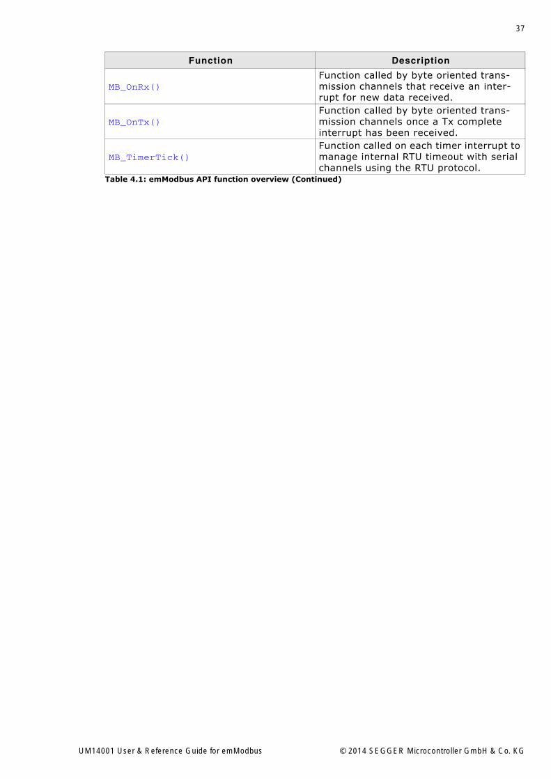
Table 4.1: emModbus API function overview
UM14001 User & Reference Guide for emModbus © 2014 SEGGER Microcontroller GmbH & Co. KG
37
MB_OnRx()Function called by byte oriented trans-mission channels that receive an inter-rupt for new data received.
MB_OnTx()Function called by byte oriented trans-mission channels once a Tx complete interrupt has been received.
MB_TimerTick()Function called on each timer interrupt to manage internal RTU timeout with serial channels using the RTU protocol.
Function Description
Table 4.1: emModbus API function overview (Continued)
UM14001 User & Reference Guide for emModbus © 2014 SEGGER Microcontroller GmbH & Co. KG
38 CHAPTER 4 Core functions
4.1.1 Channel specific core functions
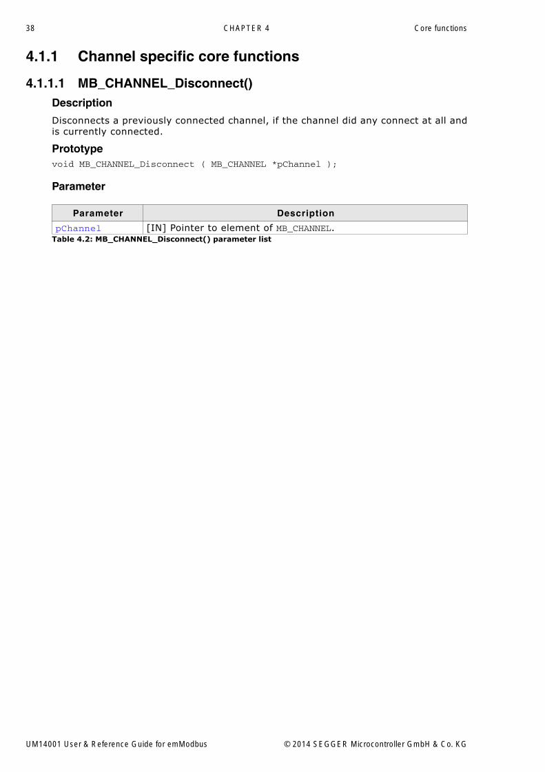
4.1.1.1 MB_CHANNEL_Disconnect()Description
Disconnects a previously connected channel, if the channel did any connect at all andis currently connected.
Prototypevoid MB_CHANNEL_Disconnect ( MB_CHANNEL *pChannel );
Parameter
Parameter Description
pChannel [IN] Pointer to element of MB_CHANNEL.Table 4.2: MB_CHANNEL_Disconnect() parameter list
UM14001 User & Reference Guide for emModbus © 2014 SEGGER Microcontroller GmbH & Co. KG
39
4.1.2 Master specific core functions
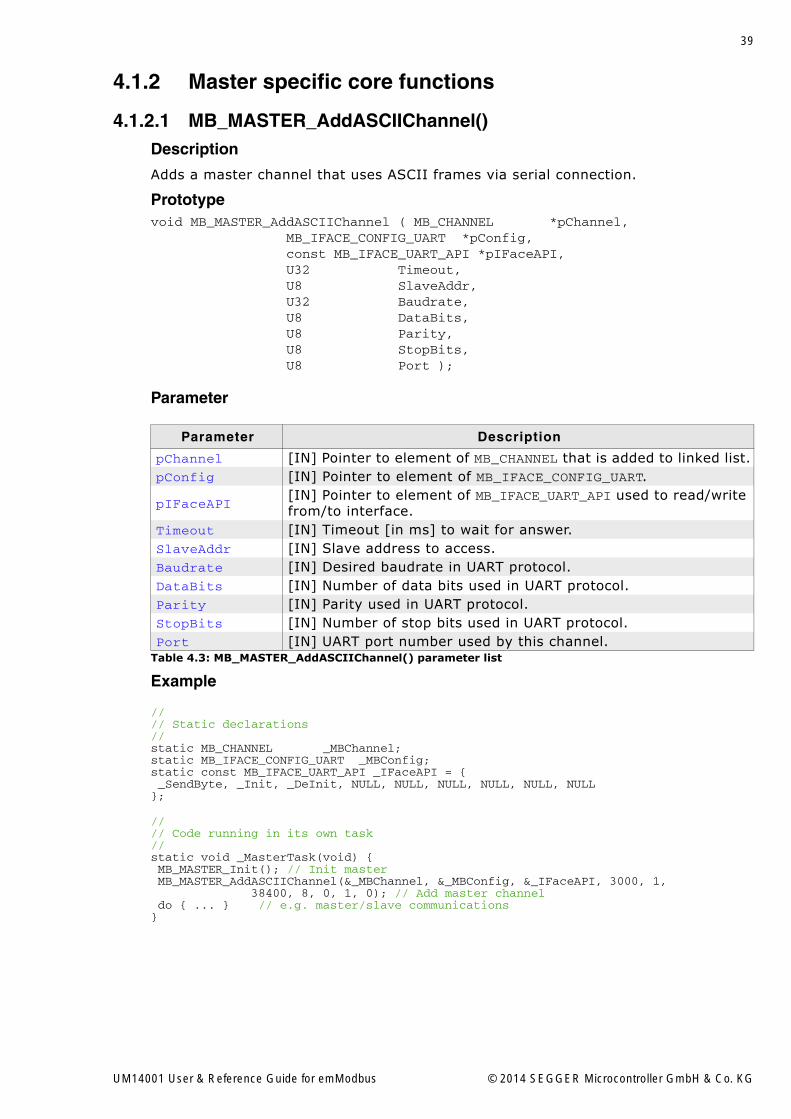
4.1.2.1 MB_MASTER_AddASCIIChannel()Description
Adds a master channel that uses ASCII frames via serial connection.
Prototypevoid MB_MASTER_AddASCIIChannel ( MB_CHANNEL *pChannel, MB_IFACE_CONFIG_UART *pConfig, const MB_IFACE_UART_API *pIFaceAPI, U32 Timeout, U8 SlaveAddr, U32 Baudrate, U8 DataBits, U8 Parity, U8 StopBits, U8 Port );
Parameter
Example
//// Static declarations//static MB_CHANNEL _MBChannel;static MB_IFACE_CONFIG_UART _MBConfig;static const MB_IFACE_UART_API _IFaceAPI = { _SendByte, _Init, _DeInit, NULL, NULL, NULL, NULL, NULL, NULL};
//// Code running in its own task//static void _MasterTask(void) { MB_MASTER_Init(); // Init master MB_MASTER_AddASCIIChannel(&_MBChannel, &_MBConfig, &_IFaceAPI, 3000, 1, 38400, 8, 0, 1, 0); // Add master channel do { ... } // e.g. master/slave communications}
Parameter Description
pChannel [IN] Pointer to element of MB_CHANNEL that is added to linked list.pConfig [IN] Pointer to element of MB_IFACE_CONFIG_UART.
pIFaceAPI[IN] Pointer to element of MB_IFACE_UART_API used to read/write from/to interface.
Timeout [IN] Timeout [in ms] to wait for answer.SlaveAddr [IN] Slave address to access.Baudrate [IN] Desired baudrate in UART protocol.DataBits [IN] Number of data bits used in UART protocol.Parity [IN] Parity used in UART protocol.StopBits [IN] Number of stop bits used in UART protocol.Port [IN] UART port number used by this channel.
Table 4.3: MB_MASTER_AddASCIIChannel() parameter list
UM14001 User & Reference Guide for emModbus © 2014 SEGGER Microcontroller GmbH & Co. KG
40 CHAPTER 4 Core functions
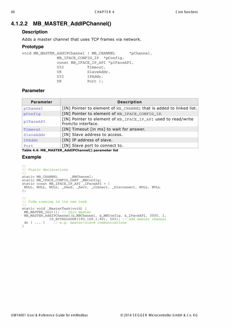
4.1.2.2 MB_MASTER_AddIPChannel()Description
Adds a master channel that uses TCP frames via network.
Prototypevoid MB_MASTER_AddIPChannel ( MB_CHANNEL *pChannel, MB_IFACE_CONFIG_IP *pConfig, const MB_IFACE_IP_API *pIFaceAPI, U32 Timeout, U8 SlaveAddr, U32 IPAddr, U8 Port );
Parameter
Example
//// Static declarations//static MB_CHANNEL _MBChannel;static MB_IFACE_CONFIG_UART _MBConfig;static const MB_IFACE_IP_API _IFaceAPI = { NULL, NULL, NULL, _Send, _Recv, _Connect, _Disconnect, NULL, NULL};
//// Code running in its own task//static void _MasterTask(void) { MB_MASTER_Init(); // Init master MB_MASTER_AddIPChannel(&_MBChannel, &_MBConfig, &_IFaceAPI, 3000, 1, IP_BYTES2ADDR(192,168,1,80), 502); // Add master channel do { ... } // e.g. master/slave communications}
Parameter Description
pChannel [IN] Pointer to element of MB_CHANNEL that is added to linked list.pConfig [IN] Pointer to element of MB_IFACE_CONFIG_IP.
pIFaceAPI[IN] Pointer to element of MB_IFACE_IP_API used to read/write from/to interface.
Timeout [IN] Timeout [in ms] to wait for answer.SlaveAddr [IN] Slave address to access.IPAddr [IN] IP address of slave.Port [IN] Slave port to connect to.
Table 4.4: MB_MASTER_AddIPChannel() parameter list
UM14001 User & Reference Guide for emModbus © 2014 SEGGER Microcontroller GmbH & Co. KG
41
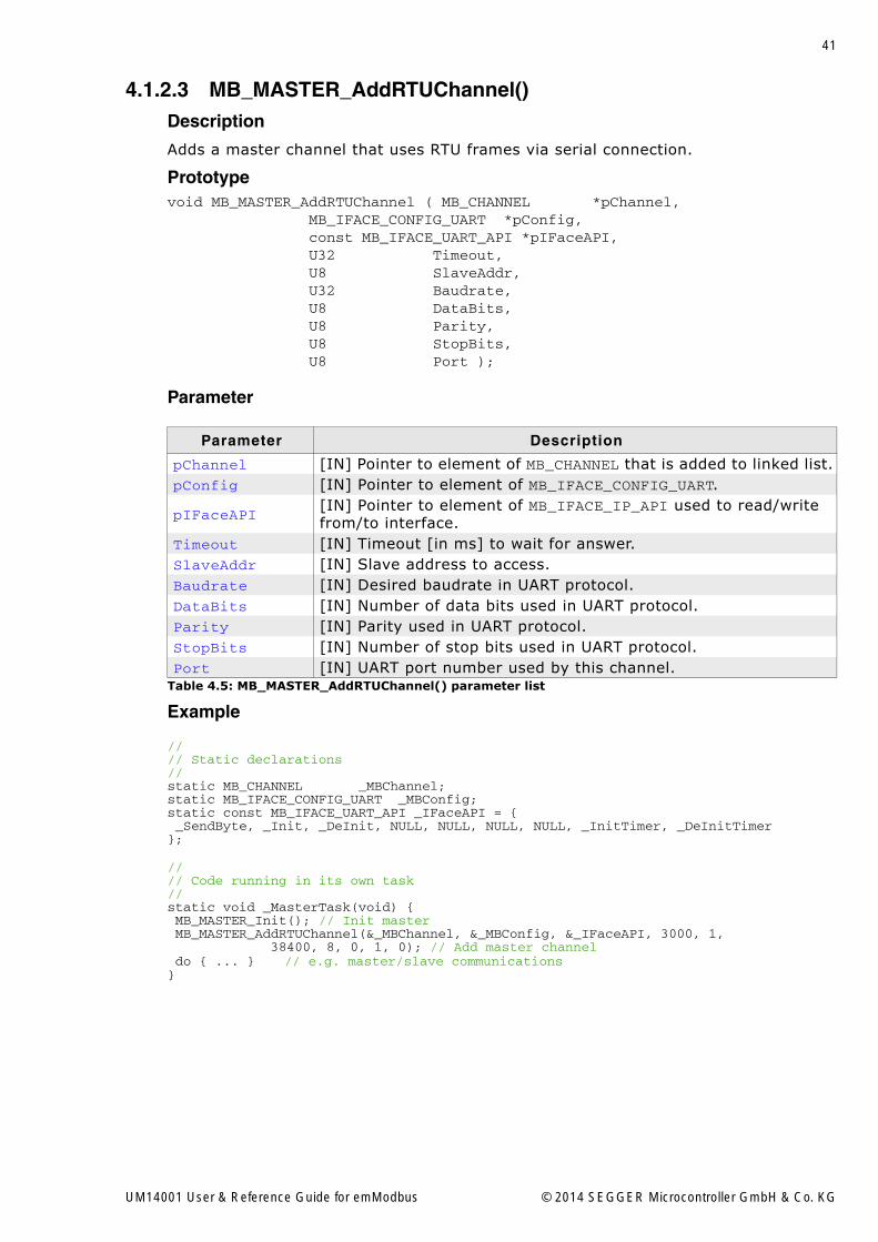
4.1.2.3 MB_MASTER_AddRTUChannel()Description
Adds a master channel that uses RTU frames via serial connection.
Prototypevoid MB_MASTER_AddRTUChannel ( MB_CHANNEL *pChannel, MB_IFACE_CONFIG_UART *pConfig, const MB_IFACE_UART_API *pIFaceAPI, U32 Timeout, U8 SlaveAddr, U32 Baudrate, U8 DataBits, U8 Parity, U8 StopBits, U8 Port );
Parameter
Example
//// Static declarations//static MB_CHANNEL _MBChannel;static MB_IFACE_CONFIG_UART _MBConfig;static const MB_IFACE_UART_API _IFaceAPI = { _SendByte, _Init, _DeInit, NULL, NULL, NULL, NULL, _InitTimer, _DeInitTimer};
//// Code running in its own task//static void _MasterTask(void) { MB_MASTER_Init(); // Init master MB_MASTER_AddRTUChannel(&_MBChannel, &_MBConfig, &_IFaceAPI, 3000, 1, 38400, 8, 0, 1, 0); // Add master channel do { ... } // e.g. master/slave communications}
Parameter Description
pChannel [IN] Pointer to element of MB_CHANNEL that is added to linked list.pConfig [IN] Pointer to element of MB_IFACE_CONFIG_UART.
pIFaceAPI[IN] Pointer to element of MB_IFACE_IP_API used to read/write from/to interface.
Timeout [IN] Timeout [in ms] to wait for answer.SlaveAddr [IN] Slave address to access.Baudrate [IN] Desired baudrate in UART protocol.DataBits [IN] Number of data bits used in UART protocol.Parity [IN] Parity used in UART protocol.StopBits [IN] Number of stop bits used in UART protocol.Port [IN] UART port number used by this channel.
Table 4.5: MB_MASTER_AddRTUChannel() parameter list
UM14001 User & Reference Guide for emModbus © 2014 SEGGER Microcontroller GmbH & Co. KG

42 CHAPTER 4 Core functions
4.1.2.4 MB_MASTER_DeInit()Description
De-Initializes the master resources and channels and removes the master endpointfrom the global endpoint list.
Prototypevoid MB_MASTER_DeInit ( void );
UM14001 User & Reference Guide for emModbus © 2014 SEGGER Microcontroller GmbH & Co. KG

43
4.1.2.5 MB_MASTER_Init()Description
Initializes the master resources and adds the master endpoint to the global endpointlist.
Prototypevoid MB_MASTER_Init ( void );
UM14001 User & Reference Guide for emModbus © 2014 SEGGER Microcontroller GmbH & Co. KG

44 CHAPTER 4 Core functions
4.1.3 Master instruction set
4.1.3.1 MB_MASTER_ReadCoils()Description
Reads coils from a slave.
Prototypeint MB_MASTER_ReadCoils ( MB_CHANNEL *pChannel, U8 *pData, U16 Addr, U16 NumItems );
Parameter
Return value
<0: Error 0: OK
Example
//// Static declarations//static int _result;static MB_CHANNEL _MBChannel;static U8 *_pData;
//// Code running in its own task//static void _MasterTask(void) { MB_MASTER_Init(); // Init master MB_MASTER_AddASCIIChannel( ... ); // Add master channel _result = MB_MASTER_ReadCoils(&_MBChannel, &_pData, 1000, 2);// Read Coils}
Parameter Description
pChannel [IN] Pointer to channel configured to interface a slave.pData [OUT] Pointer to application buffer where to store the read data.Addr [IN] Address in slave where to find the coils to access.NumItems [IN] Number of items to read.
Table 4.6: MB_MASTER_ReadCoils() parameter list
UM14001 User & Reference Guide for emModbus © 2014 SEGGER Microcontroller GmbH & Co. KG

45
4.1.3.2 MB_MASTER_ReadDI()Description
Reads Discrete Inputs from a slave.
Prototypeint MB_MASTER_ReadDI ( MB_CHANNEL *pChannel, U8 *pData, U16 Addr, U16 NumItems );
Parameter
Return value
<0: Error 0: OK
Example
//// Static declarations//static int _result;static MB_CHANNEL _MBChannel;static U8 *_pData;
//// Code running in its own task//static void _MasterTask(void) { MB_MASTER_Init(); // Init master MB_MASTER_AddASCIIChannel( ... ); // Add master channel _result = MB_MASTER_ReadDI(&_MBChannel, &_pData, 1000, 2); // Read Discrete Input}
Parameter Description
pChannel [IN] Pointer to channel configured to interface a slave.pData [OUT] Pointer to application buffer where to store the read data.Addr [IN] Address in slave where to find the inputs to access.NumItems [IN] Number of items to read.
Table 4.7: MB_MASTER_ReadDI() parameter list
UM14001 User & Reference Guide for emModbus © 2014 SEGGER Microcontroller GmbH & Co. KG

46 CHAPTER 4 Core functions
4.1.3.3 MB_MASTER_ReadHR()Description
Reads Holding Registers from a slave.
Prototypeint MB_MASTER_ReadHR ( MB_CHANNEL *pChannel, U8 *pData, U16 Addr, U16 NumItems );
Parameter
Return value
<0: Error 0: OK
Example
//// Static declarations//static int _result;static MB_CHANNEL _MBChannel;static U8 *_pData;
//// Code running in its own task//static void _MasterTask(void) { MB_MASTER_Init(); // Init master MB_MASTER_AddASCIIChannel( ... ); // Add master channel _result = MB_MASTER_ReadHR(&_MBChannel, &_pData, 1000, 2);// Read Holding Register}
Parameter Description
pChannel [IN] Pointer to channel configured to interface a slave.pData [OUT] Pointer to application buffer where to store the read data.Addr [IN] Address in slave where to find the registers to access.NumItems [IN] Number of items to read.
Table 4.8: MB_MASTER_ReadHR() parameter list
UM14001 User & Reference Guide for emModbus © 2014 SEGGER Microcontroller GmbH & Co. KG

47
4.1.3.4 MB_MASTER_ReadIR()Description
Reads Input Registers from a slave.
Prototypeint MB_MASTER_ReadIR ( MB_CHANNEL *pChannel, U8 *pData, U16 Addr, U16 NumItems );
Parameter
Return value
<0: Error 0: OK
Example
//// Static declarations//static int _result;static MB_CHANNEL _MBChannel;static U8 *_pData;
//// Code running in its own task//static void _MasterTask(void) { MB_MASTER_Init(); // Init master MB_MASTER_AddASCIIChannel( ... ); // Add master channel _result = MB_MASTER_ReadIR(&_MBChannel, &_pData, 1000, 2);// Read Input Register}
Parameter Description
pChannel [IN] Pointer to channel configured to interface a slave.pData [OUT] Pointer to application buffer where to store the read data.Addr [IN] Address in slave where to find the registers to access.NumItems [IN] Number of items to read.
Table 4.9: MB_MASTER_ReadIR() parameter list
UM14001 User & Reference Guide for emModbus © 2014 SEGGER Microcontroller GmbH & Co. KG
48 CHAPTER 4 Core functions
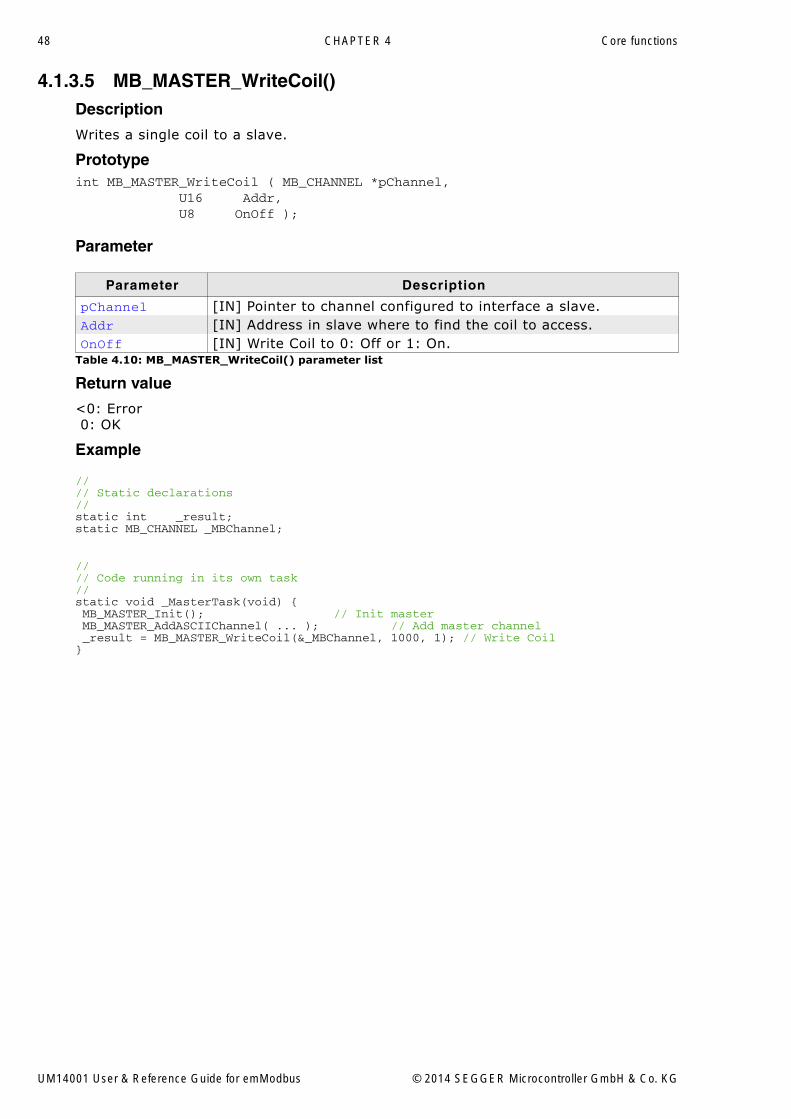
4.1.3.5 MB_MASTER_WriteCoil()Description
Writes a single coil to a slave.
Prototypeint MB_MASTER_WriteCoil ( MB_CHANNEL *pChannel, U16 Addr, U8 OnOff );
Parameter
Return value
<0: Error 0: OK
Example
//// Static declarations//static int _result;static MB_CHANNEL _MBChannel;
//// Code running in its own task//static void _MasterTask(void) { MB_MASTER_Init(); // Init master MB_MASTER_AddASCIIChannel( ... ); // Add master channel _result = MB_MASTER_WriteCoil(&_MBChannel, 1000, 1); // Write Coil}
Parameter Description
pChannel [IN] Pointer to channel configured to interface a slave.Addr [IN] Address in slave where to find the coil to access.OnOff [IN] Write Coil to 0: Off or 1: On.
Table 4.10: MB_MASTER_WriteCoil() parameter list
UM14001 User & Reference Guide for emModbus © 2014 SEGGER Microcontroller GmbH & Co. KG

49
4.1.3.6 MB_MASTER_WriteCoils()Description
Writes multiple coils to a slave
Prototypeint MB_MASTER_WriteCoils ( MB_CHANNEL *pChannel, U8 *pData, U16 Addr, U16 NumItems );
Parameter
Return value
<0: Error 0: OK
Example
//// Static declarations//static int _result;static MB_CHANNEL _MBChannel;static U8 _data;
//// Code running in its own task//static void _MasterTask(void) { MB_MASTER_Init(); // Init master MB_MASTER_AddASCIIChannel( ... ); // Add master channel _result = MB_MASTER_WriteCoils(&_MBChannel, &_data, 1000, 2);// Write Coils}
Parameter Description
pChannel [IN] Pointer to channel configured to interface a slave.
pData[IN] Pointer to application buffer where the values to write are stored.
Addr [IN] Address in slave where to find the coils to access.NumItems [IN] Number of items to write.
Table 4.11: MB_MASTER_WriteCoils() parameter list
UM14001 User & Reference Guide for emModbus © 2014 SEGGER Microcontroller GmbH & Co. KG
50 CHAPTER 4 Core functions
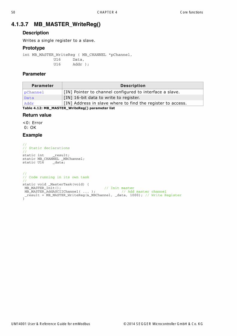
4.1.3.7 MB_MASTER_WriteReg()Description
Writes a single register to a slave.
Prototypeint MB_MASTER_WriteReg ( MB_CHANNEL *pChannel, U16 Data, U16 Addr );
Parameter
Return value
<0: Error 0: OK
Example
//// Static declarations//static int _result;static MB_CHANNEL _MBChannel;static U16 _data;
//// Code running in its own task//static void _MasterTask(void) { MB_MASTER_Init(); // Init master MB_MASTER_AddASCIIChannel( ... ); // Add master channel _result = MB_MASTER_WriteReg(&_MBChannel, _data, 1000); // Write Register}
Parameter Description
pChannel [IN] Pointer to channel configured to interface a slave.Data [IN] 16-bit data to write to register.Addr [IN] Address in slave where to find the register to access.
Table 4.12: MB_MASTER_WriteReg() parameter list
UM14001 User & Reference Guide for emModbus © 2014 SEGGER Microcontroller GmbH & Co. KG

51
4.1.3.8 MB_MASTER_WriteRegs()Description
Writes multiple registers to a slave.
Prototypeint MB_MASTER_WriteRegs ( MB_CHANNEL *pChannel, U16 *pData, U16 Addr, U16 NumItems );
Parameter
Return value
<0: Error 0: OK
Example
//// Static declarations//static volatile int _result;static MB_CHANNEL _MBChannel;static U16 _data;
//// Code running in its own task//static void _MasterTask(void) { MB_MASTER_Init(); // Init master MB_MASTER_AddASCIIChannel( ... ); // Add master channel _result = MB_MASTER_WriteRegs(&_MBChannel, &_data, 1000, 2);// Write Registers}
Parameter Description
pChannel [IN] Pointer to channel configured to interface a slave.
pData[IN] Pointer to application buffer where the values to write are stored.
Addr [IN] Address in slave where to find the registers to access.NumItems [IN] Number of items to write.
Table 4.13: MB_MASTER_WriteRegs() parameter list
UM14001 User & Reference Guide for emModbus © 2014 SEGGER Microcontroller GmbH & Co. KG

52 CHAPTER 4 Core functions
4.1.4 Slave specific core functions
4.1.4.1 MB_SLAVE_AddASCIIChannel()Description
Adds a slave channel that uses ASCII frames via serial connection.
Prototypevoid MB_SLAVE_AddASCIIChannel ( MB_CHANNEL *pChannel, MB_IFACE_CONFIG_UART *pConfig, const MB_SLAVE_API *pSlaveAPI, const MB_IFACE_UART_API *pIFaceAPI, U8 SlaveAddr, U8 DisableWrite, U32 Baudrate, U8 DataBits, U8 Parity, U8 StopBits, U8 Port );
Parameter
Example
//// Static declarations//static MB_CHANNEL _MBChannel;static MB_IFACE_CONFIG_UART _MBConfig;static const MB_IFACE_UART_API _IFaceAPI = { _SendByte, _Init, _DeInit, NULL, NULL, NULL, NULL, NULL, NULL};static const MB_SLAVE_API _SlaveAPI = { _WriteCoil, _ReadCoil, _ReadDI, _WriteReg, _ReadHR, _ReadIR};
//// Code running in main task//void MainTask(void) { MB_SLAVE_Init(); // Init slave MB_SLAVE_AddASCIIChannel(&_MBChannel, &_MBConfig, &_SlaveAPI, &_IFaceAPI, 1, 0, 38400, 8, 0, 1, 0); // Add slave channel OS_CREATETASK( ... ); // Start slave task}
Parameter Description
pChannel [IN] Pointer to element of MB_CHANNEL that is added to linked list.pConfig [IN] Pointer to element of MB_IFACE_CONFIG_UART.
pSlaveAPI[IN] Pointer to elemtent of MB_SLAVE_API used to read/write from/to target.
pIFaceAPI[IN] Pointer to element of MB_IFACE_UART_API used to read/write from/to interface.
SlaveAddr [IN] Slave address to listen on.DisableWrite [IN] Disable write access on this channel.Baudrate [IN] Desired baudrate in UART protocol.DataBits [IN] Number of data bits used in UART protocol.Parity [IN] Parity used in UART protocol.StopBits [IN] Number of stop bits used in UART protocol.Port [IN] UART port number used by this channel.
Table 4.14: MB_SLAVE_AddASCIIChannel() parameter list
UM14001 User & Reference Guide for emModbus © 2014 SEGGER Microcontroller GmbH & Co. KG
53
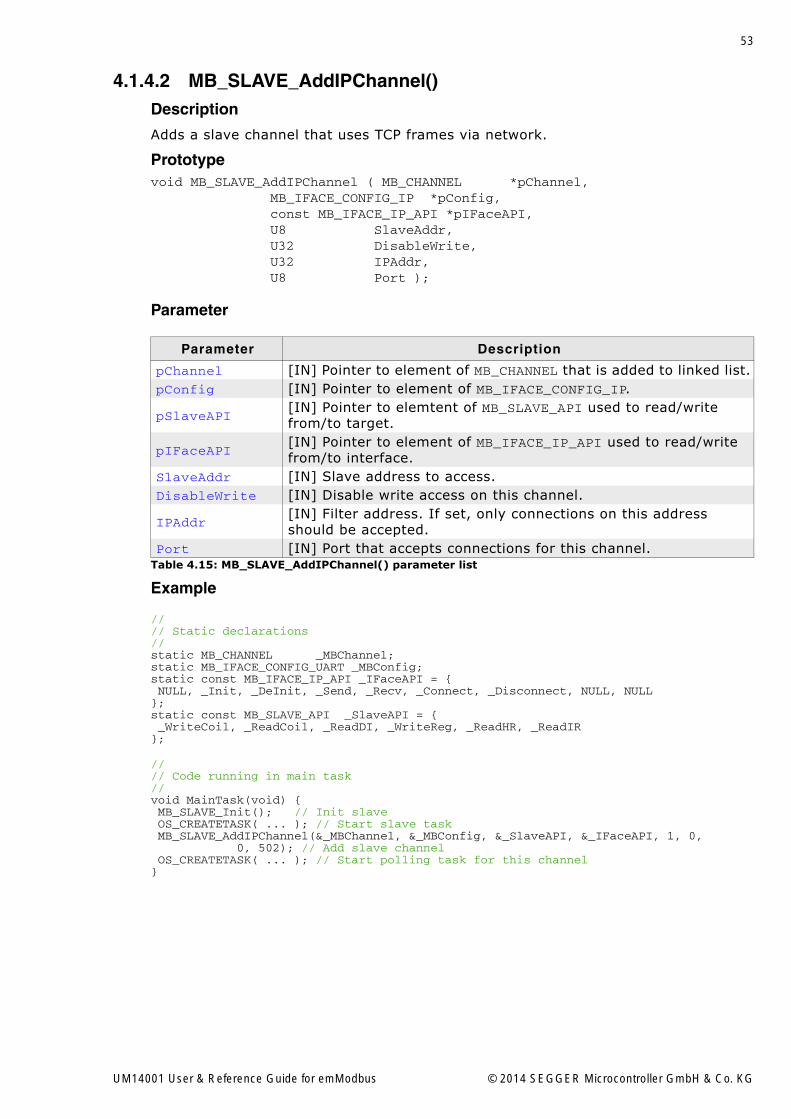
4.1.4.2 MB_SLAVE_AddIPChannel()Description
Adds a slave channel that uses TCP frames via network.
Prototypevoid MB_SLAVE_AddIPChannel ( MB_CHANNEL *pChannel, MB_IFACE_CONFIG_IP *pConfig, const MB_IFACE_IP_API *pIFaceAPI, U8 SlaveAddr, U32 DisableWrite, U32 IPAddr, U8 Port );
Parameter
Example
//// Static declarations//static MB_CHANNEL _MBChannel;static MB_IFACE_CONFIG_UART _MBConfig;static const MB_IFACE_IP_API _IFaceAPI = { NULL, _Init, _DeInit, _Send, _Recv, _Connect, _Disconnect, NULL, NULL};static const MB_SLAVE_API _SlaveAPI = { _WriteCoil, _ReadCoil, _ReadDI, _WriteReg, _ReadHR, _ReadIR };
//// Code running in main task//void MainTask(void) { MB_SLAVE_Init(); // Init slave OS_CREATETASK( ... ); // Start slave task MB_SLAVE_AddIPChannel(&_MBChannel, &_MBConfig, &_SlaveAPI, &_IFaceAPI, 1, 0, 0, 502); // Add slave channel OS_CREATETASK( ... ); // Start polling task for this channel}
Parameter Description
pChannel [IN] Pointer to element of MB_CHANNEL that is added to linked list.pConfig [IN] Pointer to element of MB_IFACE_CONFIG_IP.
pSlaveAPI[IN] Pointer to elemtent of MB_SLAVE_API used to read/write from/to target.
pIFaceAPI[IN] Pointer to element of MB_IFACE_IP_API used to read/write from/to interface.
SlaveAddr [IN] Slave address to access.DisableWrite [IN] Disable write access on this channel.
IPAddr[IN] Filter address. If set, only connections on this address should be accepted.
Port [IN] Port that accepts connections for this channel.Table 4.15: MB_SLAVE_AddIPChannel() parameter list
UM14001 User & Reference Guide for emModbus © 2014 SEGGER Microcontroller GmbH & Co. KG

54 CHAPTER 4 Core functions
4.1.4.3 MB_SLAVE_AddRTUChannel()Description
Adds a slave channel that uses RTU frames via serial connection.
Prototypevoid MB_SLAVE_AddASCIIChannel ( MB_CHANNEL *pChannel, MB_IFACE_CONFIG_UART *pConfig, const MB_SLAVE_API *pSlaveAPI, const MB_IFACE_UART_API *pIFaceAPI, U8 SlaveAddr, U8 DisableWrite, U32 Baudrate, U8 DataBits, U8 Parity, U8 StopBits, U8 Port );
Parameter
Example
//// Static declarations//static MB_CHANNEL _MBChannel;static MB_IFACE_CONFIG_UART _MBConfig;static const MB_IFACE_UART_API _IFaceAPI = { _SendByte, _Init, _DeInit, NULL, NULL, NULL, NULL, _InitTimer, _DeInitTimer };static const MB_SLAVE_API _SlaveAPI = { _WriteCoil, _ReadCoil, _ReadDI, _WriteReg, _ReadHR, _ReadIR };
//// Code running in main task//void MainTask(void) { MB_SLAVE_Init(); // Init slave MB_SLAVE_AddRTUChannel(&_MBChannel, &_MBConfig, &_SlaveAPI, &_IFaceAPI, 1, 0, 38400, 8, 0, 1, 0); // Add slave channel OS_CREATETASK( ... ); // Start slave task}}
Parameter Description
pChannel [IN] Pointer to element of MB_CHANNEL that is added to linked list.pConfig [IN] Pointer to element of MB_IFACE_CONFIG_UART.
pSlaveAPI[IN] Pointer to elemtent of MB_SLAVE_API used to read/write from/to target.
pIFaceAPI[IN] Pointer to element of MB_IFACE_UART_API used to read/write from/to interface.
SlaveAddr [IN] Slave address to listen on.DisableWrite [IN] Disable write access on this channel.Baudrate [IN] Desired baudrate in UART protocol.DataBits [IN] Number of data bits used in UART protocol.Parity [IN] Parity used in UART protocol.StopBits [IN] Number of stop bits used in UART protocol.Port [IN] UART port number used by this channel.
Table 4.16: MB_SLAVE_AddRTUChannel() parameter list
UM14001 User & Reference Guide for emModbus © 2014 SEGGER Microcontroller GmbH & Co. KG

55
4.1.4.4 MB_SLAVE_DeInit()Description
De-Initializes the slave resources and channels and removes the slave endpoint fromthe global endpoint list.
Prototypevoid MB_SLAVE_DeInit ( void );
UM14001 User & Reference Guide for emModbus © 2014 SEGGER Microcontroller GmbH & Co. KG

56 CHAPTER 4 Core functions
4.1.4.5 MB_SLAVE_Exec()Description
Loops once over all slave channels, processes data when the channel has been sig-nalled ready.
Prototypevoid MB_SLAVE_Exec ( void );
UM14001 User & Reference Guide for emModbus © 2014 SEGGER Microcontroller GmbH & Co. KG

57
4.1.4.6 MB_SLAVE_Init()Description
Initializes the slave resources and adds the slave endpoint to the global endpoint list.
Prototypevoid MB_SLAVE_Init ( void );
UM14001 User & Reference Guide for emModbus © 2014 SEGGER Microcontroller GmbH & Co. KG

58 CHAPTER 4 Core functions
4.1.4.7 MB_SLAVE_PollChannel()Description
Function that has to be periodically polled for each slave channel that requiresrequesting data instead of getting it via interrupt.
Prototypevoid MB_SLAVE_PollChannel ( MB_Channel *pChannel );
Parameter
Return value
<0: Error 0: No complete Modbus message signaled. 1: Complete Modbus message signaled.
Example
//// Polling a slave channel in a task, allowing it to sleep when possible.//static void _PollSlaveChannelTask(void *pChannel) { while (1) { MB_SLAVE_PollChannel((MB_CHANNEL*)pChannel); }}
Parameter Description
pChannel [IN] Pointer to element of MB_CHANNEL.Table 4.17: MB_SLAVE_PollChannel() parameter list
UM14001 User & Reference Guide for emModbus © 2014 SEGGER Microcontroller GmbH & Co. KG

59
4.1.4.8 MB_SLAVE_Task()Description
Wrapper function that runs MB_SLAVE_Exec() in a task.
Prototypevoid MB_SLAVE_Task ( void );
UM14001 User & Reference Guide for emModbus © 2014 SEGGER Microcontroller GmbH & Co. KG

60 CHAPTER 4 Core functions
4.1.5 Other core functions
4.1.5.1 MB_ConfigTimerFreq()Description
This function allows setting a user defined timer frequency instead of the default fre-quency of 1kHz.
Prototypevoid MB_ConfigTimerFreq ( U32 Freq );
Parameter
Parameter Description
Freq[IN] Timer frequency that shall be used for all all channels to cal-culate the RTU timeout.
Table 4.18: MB_ConfigTimerFreq() parameter list
UM14001 User & Reference Guide for emModbus © 2014 SEGGER Microcontroller GmbH & Co. KG

61
4.1.5.2 MB_OnRx()Description
Function called by byte oriented transmission channels that receive an interrupt fornew data received.
Prototypevoid MB_OnRx ( MB_CHANNEL *pChannel, U8 Data );
Parameter
Parameter Description
pChannel [IN] Pointer to element of MB_CHANNEL.Data [IN] Received character.
Table 4.19: MB_OnRx() parameter list
UM14001 User & Reference Guide for emModbus © 2014 SEGGER Microcontroller GmbH & Co. KG

62 CHAPTER 4 Core functions
4.1.5.3 MB_OnTx()Description
Function called by byte oriented transmission channels once a Tx complete interrupthas been received to send the next byte or report back that there is no more to send.
Prototypeint MB_OnTx ( MB_CHANNEL *pChannel );
Parameter
Return value
<0: Error 0: More data sent 1: No more data to send
Parameter Description
pChannel [IN] Pointer to element of MB_CHANNEL.Table 4.20: MB_OnTx() parameter list
UM14001 User & Reference Guide for emModbus © 2014 SEGGER Microcontroller GmbH & Co. KG

63
4.1.5.4 MB_TimerTick()Description
Function called on each timer interrupt to manage internal RTU timeout with serialchannels using the RTU protocol.
Prototypevoid MB_TimerTick ( void );
UM14001 User & Reference Guide for emModbus © 2014 SEGGER Microcontroller GmbH & Co. KG
64 CHAPTER 4 Core functions
4.2 emModbus data structures
4.2.1 Interface configuration structures
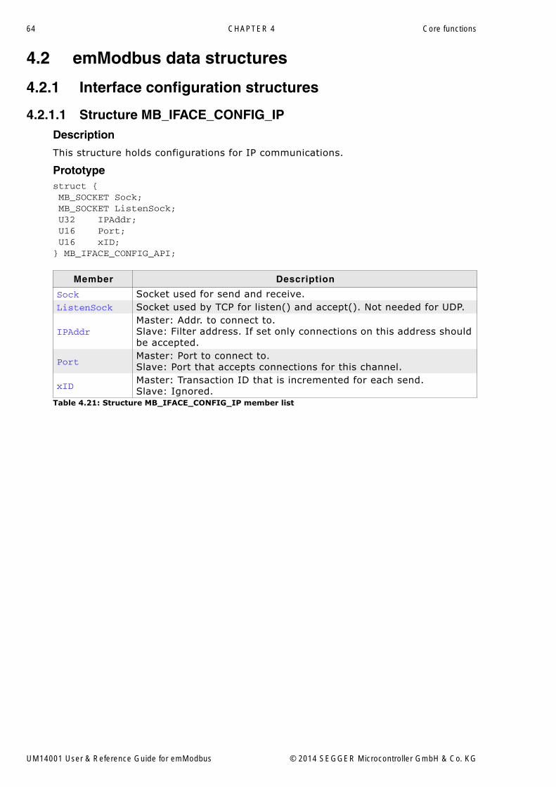
4.2.1.1 Structure MB_IFACE_CONFIG_IPDescription
This structure holds configurations for IP communications.
Prototypestruct { MB_SOCKET Sock; MB_SOCKET ListenSock; U32 IPAddr; U16 Port; U16 xID;} MB_IFACE_CONFIG_API;
Member Description
Sock Socket used for send and receive.ListenSock Socket used by TCP for listen() and accept(). Not needed for UDP.
IPAddrMaster: Addr. to connect to.Slave: Filter address. If set only connections on this address should be accepted.
PortMaster: Port to connect to.Slave: Port that accepts connections for this channel.
xIDMaster: Transaction ID that is incremented for each send.Slave: Ignored.
Table 4.21: Structure MB_IFACE_CONFIG_IP member list
UM14001 User & Reference Guide for emModbus © 2014 SEGGER Microcontroller GmbH & Co. KG

65
4.2.1.2 Structure MB_IFACE_CONFIG_UARTDescription
This structure holds configurations for UART communications.
Prototypestruct { U32 Cnt; U32 CntReload; U32 Baudrate; U8 DataBits; U8 Parity; U8 StopBits; U8 Port;} MB_IFACE_CONFIG_UART;
Additional information
MB_IFACE_CONFIG is of type MB_IFACE_CONFIG_UART.
Member Description
Cnt RTU timeout countdown.CntReload RTU countdown reload value.Baudrate Baudrate to use.DataBits Number of data bits.Parity Parity as interpreted by application.StopBits Number of stop bits.Port Interface index.
Table 4.22: Structure MB_IFACE_CONFIG_UART member list
UM14001 User & Reference Guide for emModbus © 2014 SEGGER Microcontroller GmbH & Co. KG

66 CHAPTER 4 Core functions
4.2.2 Interface function structures
4.2.2.1 Structure MB_IFACE_IP_APIDescription
This structure holds function pointers for IP communications.
Prototype
struct { void ( *pfSendByte ) ( MB_IFACE_CONFIG_UART *pConfig, U8 Data ); int ( *pfInit ) ( MB_IFACE_CONFIG_UART *pConfig ); void ( *pfDeInit ) ( MB_IFACE_CONFIG_UART *pConfig ); int ( *pfSend ) ( MB_IFACE_CONFIG_UART *pConfig, const U8 *pData, U32 NumBytes ); int ( *pfRecv ) ( MB_IFACE_CONFIG_UART *pConfig, U8 *pData, U32 NumBytes, U32 Timeout ); int ( *pfConnect ) ( MB_IFACE_CONFIG_UART *pConfig, U32 Timeout ); void ( *pfDisconnect ) ( MB_IFACE_CONFIG_UART *pConfig ); void ( *pfInitTimer ) ( U32 MaxFreq ); void ( *pfDeInitTimer ) ( void );} MB_IFACE_IP_API;
Member Description
pfSendByteSend first byte. Every next byte will be sent via MB_OnTx() from interrupt.NULL if stream oriented interface, as pfSendByte gets used instead.
pfInitInit IP and get listen socket and bring it in listen state if needed.NULL if not needed.
pfDeInitClose listen socket and de-init IP.NULL if not needed.
pfSendSend data for stream oriented interface.NULL if byte oriented interface is used, as pfSend gets used instead.
pfRecv Request more data.
pfConnectMaster: Connect to slave.Slave: Accept connection if needed.NULL if not needed.
pfDisconnectMaster: Disconnect from slave.Slave: Close connection if needed.NULL if not needed.
pfInitTimer NULL.pfDeInitTimer NULL.
Table 4.23: Structure MB_IFACE_IP_API member list
UM14001 User & Reference Guide for emModbus © 2014 SEGGER Microcontroller GmbH & Co. KG

67
4.2.2.2 Structure MB_IFACE_UART_APIDescription
This structure holds function pointers for UART communications.
Prototypestruct { void ( *pfSendByte ) ( MB_IFACE_CONFIG_UART *pConfig, U8 Data ); int ( *pfInit ) ( MB_IFACE_CONFIG_UART *pConfig ); void ( *pfDeInit ) ( MB_IFACE_CONFIG_UART *pConfig ); int ( *pfSend ) ( MB_IFACE_CONFIG_UART *pConfig, const U8 *pData, U32 NumBytes ); int ( *pfRecv ) ( MB_IFACE_CONFIG_UART *pConfig, U8 *pData, U32 NumBytes, U32 Timeout ); int ( *pfConnect ) ( MB_IFACE_CONFIG_UART *pConfig, U32 Timeout ); void ( *pfDisconnect ) ( MB_IFACE_CONFIG_UART *pConfig ); void ( *pfInitTimer ) ( U32 MaxFreq ); void ( *pfDeInitTimer ) ( void );} MB_IFACE_UART_API;
Additional information
MB_IFACE_API is of type MB_IFACE_UART_API.
Member Description
pfSendByteSend first byte. Every next byte will be sent via MB_OnTx() from interrupt.NULL if stream oriented interface, as pfSend gets used instead.
pfInitInit hardware.NULL if not needed.
pfDeInitDe-Init hardware.NULL if not needed.
pfSendSend data for stream oriented interface.NULL if byte oriented interface, as pfSendByte gets used instead.
pfRecvTypically data is received via MB_OnRx() from interrupt.NULL if not using polling mode.
pfConnect NULL.pfDisconnect NULL.
pfInitTimerTypically needed for RTU interfaces only. Initializes a timer needed for RTU timeout.NULL if not needed.
pfDeInitTimerDe-initialize RTU timer.NULL if not needed.
Table 4.24: Structure MB_IFACE_UART_API member list
UM14001 User & Reference Guide for emModbus © 2014 SEGGER Microcontroller GmbH & Co. KG

68 CHAPTER 4 Core functions
4.2.3 Slave structures
4.2.3.1 Structure MB_SLAVE_APIDescription
This structure holds function pointers used by slaves.
Prototypestruct { int ( *pfWriteCoil ) ( U16 Addr, char OnOff ); int ( *pfReadCoil ) ( U16 Addr ); int ( *pfReadDI ) ( U16 Addr ); int ( *pfWriteReg ) ( U16 Addr, U16 Val ); int ( *pfReadHR ) ( U16 Addr, U16 *pVal ); int ( *pfReadIR ) ( U16 Addr, U16 *pVal );} MB_SLAVE_API;
Member Description
pfReadCoil Read coil status.pfReadDI Read discrete input registers.pfReadHR Read holding register.pfReadIR Read input register.pfWriteCoil Write coil.pfWriteReg Write register.
Table 4.25: Structure MB_SLAVE_API member list
UM14001 User & Reference Guide for emModbus © 2014 SEGGER Microcontroller GmbH & Co. KG

69
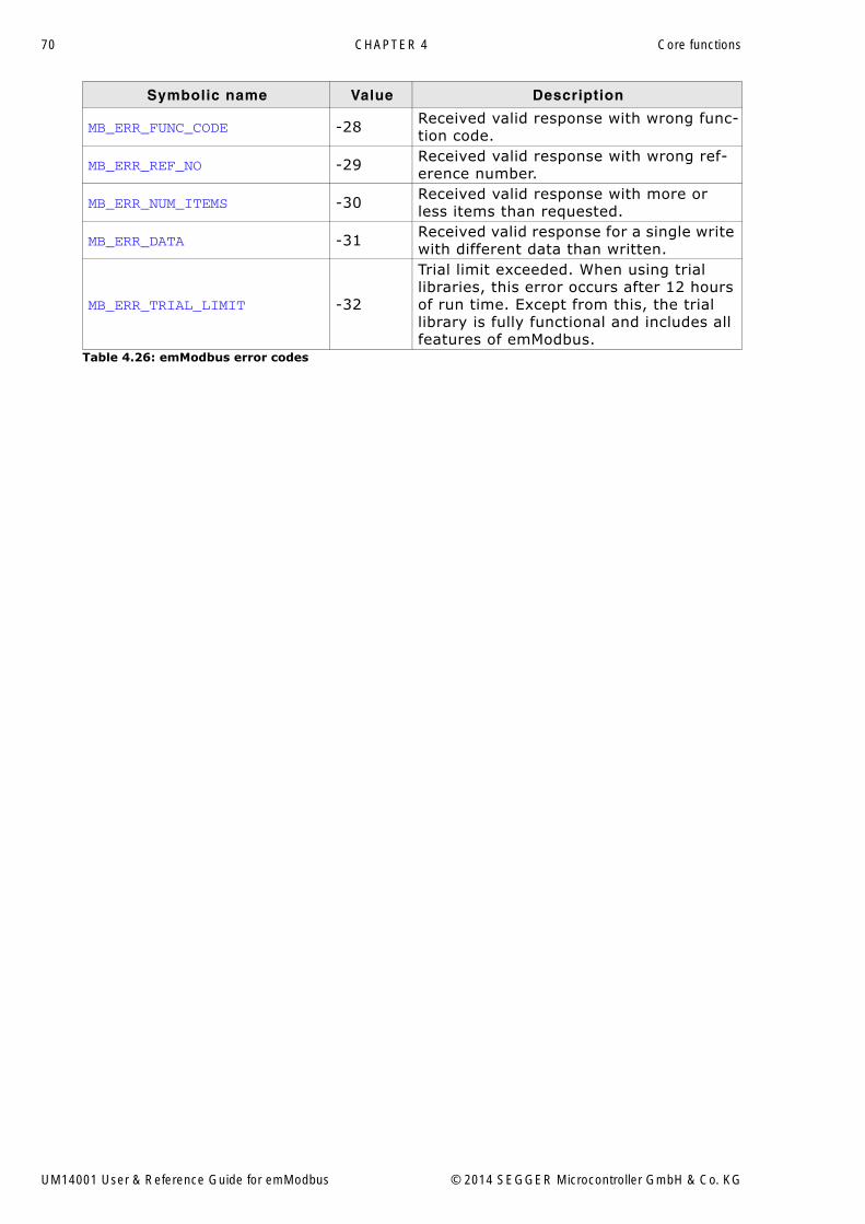
4.3 Error codesThe following table contains a list of emModbus error codes.Generally, success is indicated by 0 and definite errors are indicated by negativenumbers.
Symbolic name Value Description
Slave errors
MB_ERR_ILLEGAL_FUNC -1
The function code received in the query is an illegal function code for the slave. This may be because the function code was not implemented in the selected device. It could also indicate that the slave is in the wrong state to process a request of this type.
MB_ERR_ILLEGAL_DATA_ADDR -2
The data address received in the query is an invalid address for the slave. More specifically, the combination of reference number and transfer length is invalid.
MB_ERR_ILLEGAL_DATA_VAL -3
A value contained in the query data field is an invalid value for the slave. This indi-cates a fault in the structure of a request, such as an incorrect implied length.
MB_ERR_SLAVE_FAIL -4An unrecoverable error occurred while the slave was attempting to perform the requested action.
MB_ERR_ACK -5
The slave has accepted the request and is processing it, but a long duration of time will be required to do so. This response is returned to prevent a timeout error from occurring in the master, which can then poll for process completion.
MB_ERR_SLAVE_BUSY -6The slave is engaged in processing a long�duration command. The master should retransmit the message later.
MB_ERR_NACK -7The requested function cannot be per-formed. Issue poll to obtain detailed device dependent error information.
MB_ERR_MEM_PARITY_ERR -8
The slave attempted to perform the query, but detected a parity error in the memory. The master can retry the request, but service may be required on the slave device.
Stack internal errorsMB_ERR_MISC -20 Unspecified error.MB_ERR_CONNECT -21 Error while connecting.MB_ERR_CONNECT_TIMEOUT -22 Timeout while connecting.MB_ERR_DISCONNECT -23 Interface signaled disconnect.MB_ERR_TIMEOUT -24 No answer received on request.
MB_ERR_CHECKSUM -25 Received message did not pass LRC/CRC check.
MB_ERR_PARAM -26 Parameter error in API call.
MB_ERR_SLAVE_ADDR -27 Received valid response with wrong slave address.
Table 4.26: emModbus error codes
UM14001 User & Reference Guide for emModbus © 2014 SEGGER Microcontroller GmbH & Co. KG
70 CHAPTER 4 Core functions
MB_ERR_FUNC_CODE -28 Received valid response with wrong func-tion code.
MB_ERR_REF_NO -29 Received valid response with wrong ref-erence number.
MB_ERR_NUM_ITEMS -30 Received valid response with more or less items than requested.
MB_ERR_DATA -31 Received valid response for a single write with different data than written.
MB_ERR_TRIAL_LIMIT -32
Trial limit exceeded. When using trial libraries, this error occurs after 12 hours of run time. Except from this, the trial library is fully functional and includes all features of emModbus.
Symbolic name Value Description
Table 4.26: emModbus error codes
UM14001 User & Reference Guide for emModbus © 2014 SEGGER Microcontroller GmbH & Co. KG
71
Chapter 5
Configuring emModbus
emModbus can be used without changing any of the compile-time flags. All compile-time configuration flags are preconfigured with valid values, which match therequirements of most applications.
The default configuration of emModbus can be changed via compile-time flags whichcan be added to MB_Conf.h. MB_Conf.h is the main configuration file for the emMod-bus stack.
UM14001 User & Reference Guide for emModbus © 2014 SEGGER Microcontroller GmbH & Co. KG

72 CHAPTER 5 Configuring emModbus
5.1 Compile-time configurationThe following types of configuration macros exist:
Binary switches "B"
Switches can have a value of either 0 or 1, for deactivated and activated respectively.Actually, anything other than 0 works, but 1 makes it easier to read a configurationfile. These switches can enable or disable a certain functionality or behavior.Switches are the simplest form of configuration macros.
Numerical values "N"
Numerical values are used somewhere in the code in place of a numerical constant. Atypical example is the configuration of the sector size of a storage medium.
Function replacements "F"
Macros can basically be treated like regular functions although certain limitationsapply, as a macro is still put into the code as simple text replacement. Functionreplacements are mainly used to add specific functionality to a module which ishighly hardware-dependent. This type of macro is always declared using brackets(and optional parameters).
5.1.1 Compile-time configuration switches
Type Symbolic name Default Description
System configuration macros
B MB_IS_BIGENDIAN 0 Macro to define if a big endian tar-get is used.
Debug macros
N MB_DEBUG 0
Macro to define the debug level of the emModbus build. Refer to Debug level on page 73 for a description of the different debug level.
Optimization macros
F MB_MEMCMP
memcmp(C-routine in standard C-library)
Macro to define an optimized memcmp routine to speed up the stack. An optimized memcmp rou-tine is typically implemented in assembly language.
F MB_MEMCPY
memcpy(C-routine in standard C-library)
Macro to define an optimized memcpy routine to speed up the stack. An optimized memcpy rou-tine is typically implemented in assembly language.Optimized versions for IAR and GCC compilers are supplied.
F MB_MEMMOVE
memmove(C-routine in standard C-library)
Macro to define an optimized memmove routine to speed up the stack. An optimized memmove routine is typically implemented in assembly language.
F MB_MEMSET
memset(C-routine in standard C-library)
Macro to define an optimized memset routine to speed up the stack. An optimized memset rou-tine is typically implemented in assembly language.
UM14001 User & Reference Guide for emModbus © 2014 SEGGER Microcontroller GmbH & Co. KG

73
5.1.2 Debug levelemModbus can be configured to display debug information at higher debug levels tolocate a problem (Error) or potential problem. To display information, emModbususes the logging routines (see chapter Debugging on page 75). These routines canbe blank, they are not required for the functionality of emModbus. In a target sys-tem, they are typically not required in a release (production) build, since a produc-tion build typically uses a lower debug level.
If (IP_DEBUG == 0): used for release builds. Includes no debug options.If (IP_DEBUG == 1): MP_PANIC() is mapped to MP_Panic().If (IP_DEBUG >= 2): MP_PANIC() is mapped to MP_Panic() and logging support isactivated.
UM14001 User & Reference Guide for emModbus © 2014 SEGGER Microcontroller GmbH & Co. KG

74 CHAPTER 5 Configuring emModbus
UM14001 User & Reference Guide for emModbus © 2014 SEGGER Microcontroller GmbH & Co. KG

75
Chapter 6
Debugging
emModbus comes with debugging options including optional warning and log outputs.
UM14001 User & Reference Guide for emModbus © 2014 SEGGER Microcontroller GmbH & Co. KG

76 CHAPTER 6 Debugging
6.1 Message outputThe debug builds of emModbus include a debug system which helps to analyze thecorrect implementation of the stack in your application. All modules can output log-ging and warning messages via terminal I/O.
UM14001 User & Reference Guide for emModbus © 2014 SEGGER Microcontroller GmbH & Co. KG
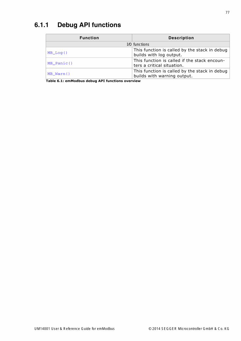
77
6.1.1 Debug API functions
Function Description
I/O functions
MB_Log()This function is called by the stack in debug builds with log output.
MB_Panic()This function is called if the stack encoun-ters a critical situation.
MB_Warn()This function is called by the stack in debug builds with warning output.
Table 6.1: emModbus debug API functions overview
UM14001 User & Reference Guide for emModbus © 2014 SEGGER Microcontroller GmbH & Co. KG

78 CHAPTER 6 Debugging
6.1.1.1 MB_Log()Description
This function is called by the stack in debug builds with log output. In a release build,this function may not be linked in.
Prototypevoid MB_Log ( const char *s );
Parameter
Parameter Description
s [IN] String to output.Table 6.2: MB_Log() parameter list
UM14001 User & Reference Guide for emModbus © 2014 SEGGER Microcontroller GmbH & Co. KG
79
6.1.1.2 MB_Panic()Description
This function is called if the stack encounters a critical situation. In a release build,this function may not be linked in.
Prototypevoid MB_Panic ( const char *s );
Parameter
Parameter Description
s [IN] String to output before running into endless loop.Table 6.3: MB_Panic() parameter list
UM14001 User & Reference Guide for emModbus © 2014 SEGGER Microcontroller GmbH & Co. KG
80 CHAPTER 6 Debugging
6.1.1.3 MB_Warn()Description
This function is called by the stack in debug builds with warning output. In a releasebuild, this function may not be linked in.
Prototypevoid MB_Warn ( const char *s );
Parameter
Parameter Description
s [IN] String to output.Table 6.4: MB_Warn() parameter list
UM14001 User & Reference Guide for emModbus © 2014 SEGGER Microcontroller GmbH & Co. KG

81
6.2 Using a network sniffer to analyse ethernet com-munication problems
Using a network sniffer to analyze your local Ethernet traffic may give you a deeperunderstanding of the data that is being sent in your network. For this purpose youcan use several network sniffers. Some of them are available for free such as Wire-shark. An example of a network sniff using Wireshark is shown in the screenshotbelow:
UM14001 User & Reference Guide for emModbus © 2014 SEGGER Microcontroller GmbH & Co. KG

82 CHAPTER 6 Debugging
6.3 Testing emModbus applicationsWe recommend testing emModbus devices by using their respective counterparts,e.g. using a emModbus/TCP master to test a emModbus/TCP slave and vice versa.Alternatively, devices can also be tested with a desktop computer running an appro-piate Modbus application.
To solely test emModbus on target hardware, we recommend building a correspond-ing project for the specific application. For example, the application contained inOS_IP_MB_SlaveTCP.c, can be tested using a project for the application contained inOS_IP_MB_MasterTCP.c. Configuration of some parameters (e.g. IP address) isrequired before compiling the project and downloading the output into a second tar-get. When connected to the same network, both devices should then start communi-cation with each other.
To test emModbus using a desktop computer, an appropiate software package isrequired. The shipment contains Windows applications for Modbus master and slavedevices using Modbus/TCP, which can be used to test both devices via that connec-tion. In addition, several vendors offer Modbus testing applications for Microsoft Win-dows and other operating systems, many of which are free or at least free toevaluate for a limited time. We recommend "Modbus Poll" for testing emModbus slavefunctionalities and "Modbus Slave" for testing emModbus master functionalities. Bothapplications can be downloaded from http://www.modbustools.com.
UM14001 User & Reference Guide for emModbus © 2014 SEGGER Microcontroller GmbH & Co. KG

83
Chapter 7
OS Integration
emModbus is designed to be used in a multitasking environment. The interface to theoperating system is encapsulated in a single file, the MB/OS interface. For embOS, allfunctions required for this MB/OS interface are implemented in a single file whichcomes with emModbus.
This chapter provides descriptions of the functions required to fully support emMod-bus in multitasking environments.
UM14001 User & Reference Guide for emModbus © 2014 SEGGER Microcontroller GmbH & Co. KG

84 CHAPTER 7 OS Integration
7.1 General informationAll OS interface functions for embOS are implemented in MB_OS_embOS.c, which islocated in the root folder of the emModbus stack.
UM14001 User & Reference Guide for emModbus © 2014 SEGGER Microcontroller GmbH & Co. KG
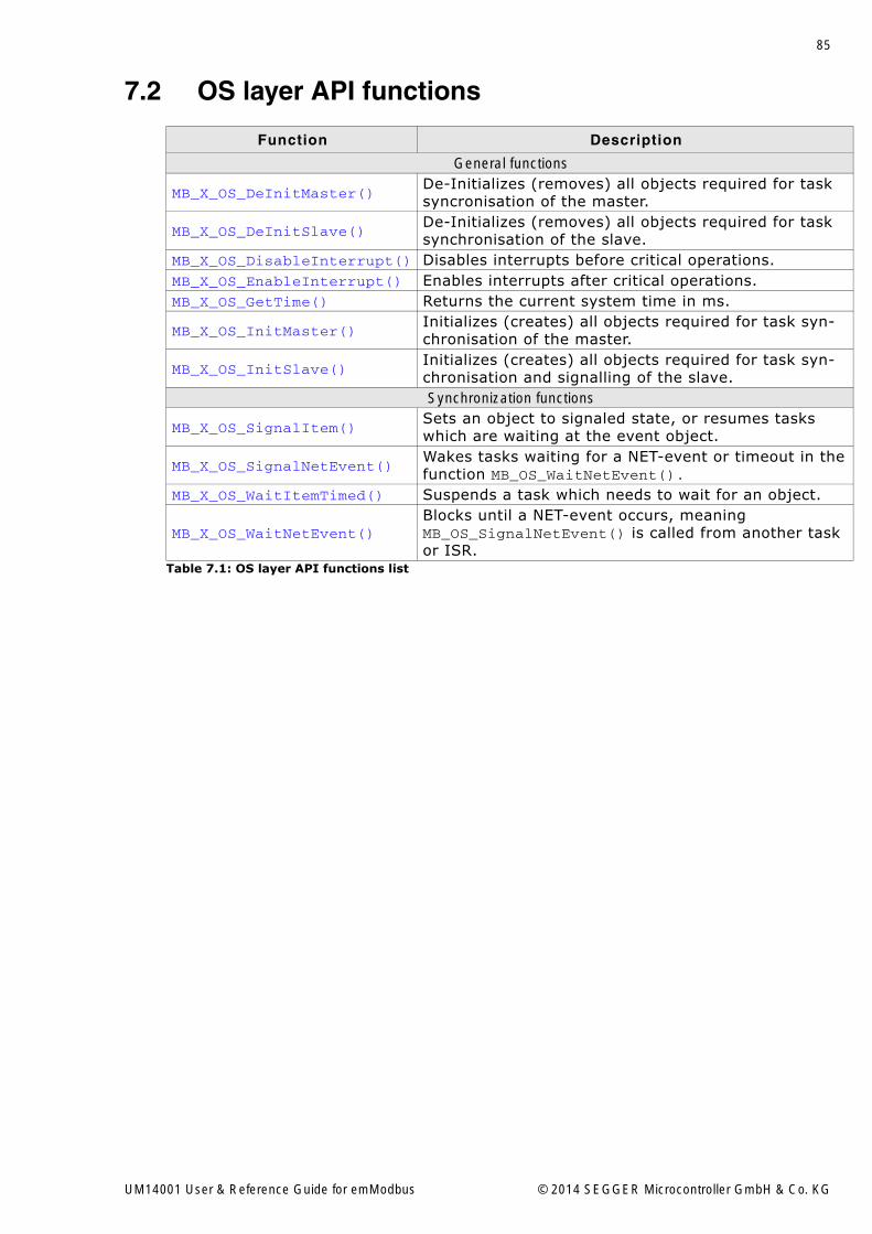
85
7.2 OS layer API functions
Function Description
General functions
MB_X_OS_DeInitMaster()De-Initializes (removes) all objects required for task syncronisation of the master.
MB_X_OS_DeInitSlave()De-Initializes (removes) all objects required for task synchronisation of the slave.
MB_X_OS_DisableInterrupt() Disables interrupts before critical operations.MB_X_OS_EnableInterrupt() Enables interrupts after critical operations.MB_X_OS_GetTime() Returns the current system time in ms.
MB_X_OS_InitMaster()Initializes (creates) all objects required for task syn-chronisation of the master.
MB_X_OS_InitSlave()Initializes (creates) all objects required for task syn-chronisation and signalling of the slave.Synchronization functions
MB_X_OS_SignalItem()Sets an object to signaled state, or resumes tasks which are waiting at the event object.
MB_X_OS_SignalNetEvent()Wakes tasks waiting for a NET-event or timeout in thefunction MB_OS_WaitNetEvent().
MB_X_OS_WaitItemTimed() Suspends a task which needs to wait for an object.
MB_X_OS_WaitNetEvent()Blocks until a NET-event occurs, meaning MB_OS_SignalNetEvent() is called from another task or ISR.
Table 7.1: OS layer API functions list
UM14001 User & Reference Guide for emModbus © 2014 SEGGER Microcontroller GmbH & Co. KG

86 CHAPTER 7 OS Integration
7.2.1 General functions
7.2.1.1 MB_X_OS_DeInitMaster()Description
De-Initializes (removes) all objects required for task syncronisation of the master.
Prototypevoid MB_X_OS_DeInitMaster ( void );
UM14001 User & Reference Guide for emModbus © 2014 SEGGER Microcontroller GmbH & Co. KG

87
7.2.1.2 MB_X_OS_DeInitSlave()Description
De-Initializes (removes) all objects required for task syncronisation of the slave.
Prototypevoid MB_X_OS_DeInitSlave ( void );
UM14001 User & Reference Guide for emModbus © 2014 SEGGER Microcontroller GmbH & Co. KG

88 CHAPTER 7 OS Integration
7.2.1.3 MB_X_OS_DisableInterrupt()Description
Disables interrupts before critical operations.
Prototypevoid MB_X_OS_DisableInterrupt ( void );
UM14001 User & Reference Guide for emModbus © 2014 SEGGER Microcontroller GmbH & Co. KG

89
7.2.1.4 MB_X_OS_EnableInterrupt()Description
Enables interrupts after critical operations.
Prototypevoid MB_X_OS_EnableInterrupt ( void );
UM14001 User & Reference Guide for emModbus © 2014 SEGGER Microcontroller GmbH & Co. KG

90 CHAPTER 7 OS Integration
7.2.1.5 MB_X_OS_GetTime()Description
Returns the current system time in ms. The value will wrap around after approxi-mately 49.7 days. This is taken into account by the stack.
Prototype
U32 MB_X_OS_GetTime32 ( void );
Return value
System time in ms.
UM14001 User & Reference Guide for emModbus © 2014 SEGGER Microcontroller GmbH & Co. KG

91
7.2.1.6 MB_X_OS_InitMaster()Description
Initializes (creates) all objects required for task syncronisation of the master. This isone semaphore for protection of critical code, which may not be executed from multi-ple tasks at the same time, and a hook in case a task currently executing Modbusmaster API is terminated.
Prototypevoid MB_X_OS_InitMaster ( void );
UM14001 User & Reference Guide for emModbus © 2014 SEGGER Microcontroller GmbH & Co. KG

92 CHAPTER 7 OS Integration
7.2.1.7 MB_X_OS_InitSlave()Description
Initializes (creates) all objects required for task synchronisation and signalling of theslave.
Prototypevoid MB_X_OS_InitSlave ( void );
UM14001 User & Reference Guide for emModbus © 2014 SEGGER Microcontroller GmbH & Co. KG

93
7.2.2 Synchronization functions
7.2.2.1 MB_X_OS_SignalItem()Description
Sets an object to signaled state, or resumes tasks which are waiting at the eventobject.
Prototypevoid MB_X_OS_SignalItem (void *pWaitItem );
Parameter
Parameter Description
pWaitItem [IN] Pointer to item a task is waiting for.Table 7.2: MB_X_OS_SignalItem() parameter list
UM14001 User & Reference Guide for emModbus © 2014 SEGGER Microcontroller GmbH & Co. KG

94 CHAPTER 7 OS Integration
7.2.2.2 MB_X_OS_SignalNetEvent()Description
Wakes tasks waiting for a NET-event or timeout in the functionMB_OS_WaitNetEvent().
Prototypevoid MB_X_OS_SignalNetEvent ( void );
UM14001 User & Reference Guide for emModbus © 2014 SEGGER Microcontroller GmbH & Co. KG

95
7.2.2.3 MB_X_OS_WaitItemTimed()Description
Suspends a task which needs to wait for an object. This object is identified by apointer to it and can be of any type, e.g. channel.
Prototypevoid MB_X_OS_WaitItemTimed ( void *pWaitItem, unsigned Timeout );
Parameter
Parameter Description
pWaitItem[IN] Pointer to item a task shall wait for until signalled or timeout occurs.
Timeout [IN] Timeout [in ms] to wait for item to be signalled.Table 7.3: MB_X_OS_WaitItemTimed() parameter list
UM14001 User & Reference Guide for emModbus © 2014 SEGGER Microcontroller GmbH & Co. KG

96 CHAPTER 7 OS Integration
7.2.2.4 MB_X_OS_WaitNetEvent()Description
Called from MB_Task() only. Blocks until a NET-event occurs, meaningMB_OS_SignalNetEvent() is called from another task or ISR.
Prototypevoid MB_X_OS_WaitNetEvent ( unsigned ms );
Parameter
Parameter Description
ms [IN] Time to wait for a NET-event to occur [in ms]. 0 for infinite.Table 7.4: MB_X_OS_WaitNetEvent() parameter list
UM14001 User & Reference Guide for emModbus © 2014 SEGGER Microcontroller GmbH & Co. KG

97
Chapter 8
Resource usage
This chapter covers the resource usage of emModbus. It contains information aboutthe memory requirements in typical systems, which can be used to obtain sufficientestimates for most target systems.
UM14001 User & Reference Guide for emModbus © 2014 SEGGER Microcontroller GmbH & Co. KG
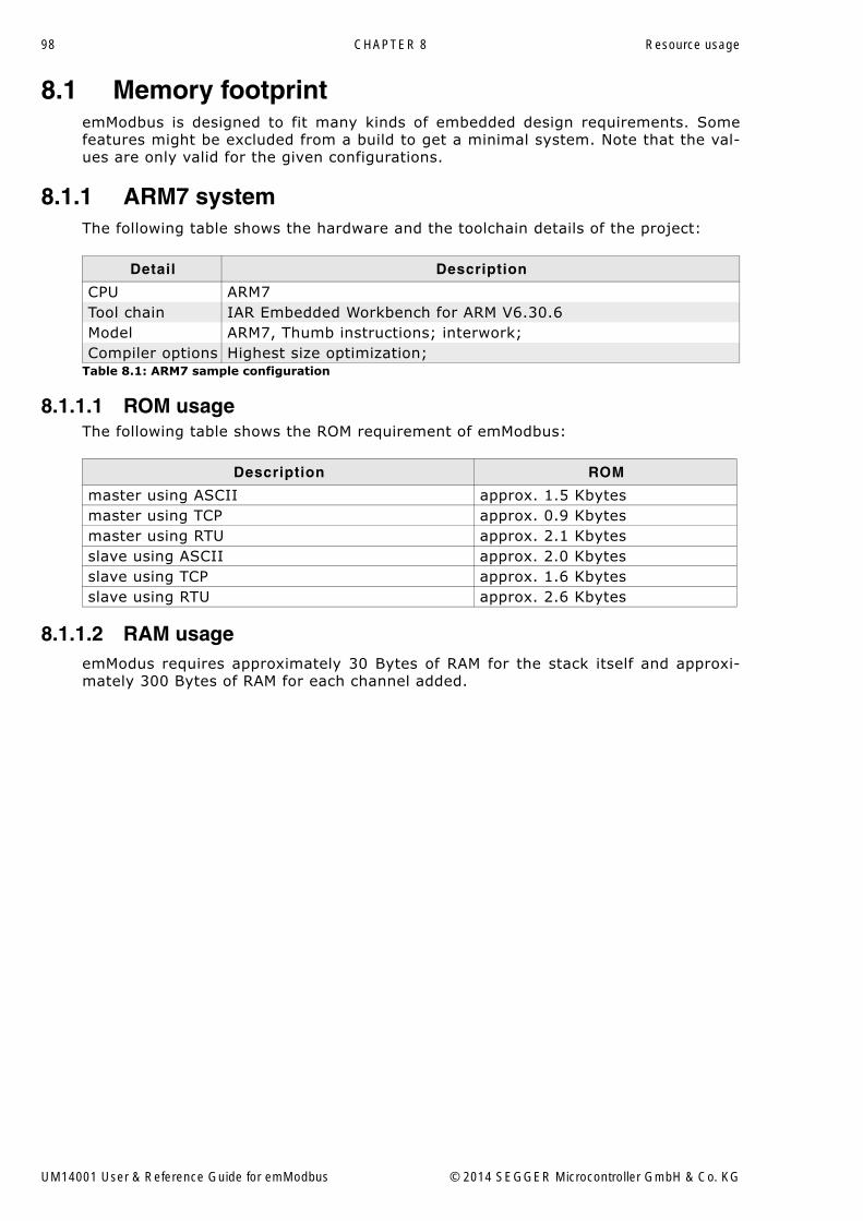
98 CHAPTER 8 Resource usage
8.1 Memory footprintemModbus is designed to fit many kinds of embedded design requirements. Somefeatures might be excluded from a build to get a minimal system. Note that the val-ues are only valid for the given configurations.
8.1.1 ARM7 systemThe following table shows the hardware and the toolchain details of the project:
8.1.1.1 ROM usageThe following table shows the ROM requirement of emModbus:
8.1.1.2 RAM usageemModus requires approximately 30 Bytes of RAM for the stack itself and approxi-mately 300 Bytes of RAM for each channel added.
Detail Description
CPU ARM7Tool chain IAR Embedded Workbench for ARM V6.30.6Model ARM7, Thumb instructions; interwork;Compiler options Highest size optimization;
Table 8.1: ARM7 sample configuration
Description ROM
master using ASCII approx. 1.5 Kbytesmaster using TCP approx. 0.9 Kbytesmaster using RTU approx. 2.1 Kbytesslave using ASCII approx. 2.0 Kbytesslave using TCP approx. 1.6 Kbytesslave using RTU approx. 2.6 Kbytes
UM14001 User & Reference Guide for emModbus © 2014 SEGGER Microcontroller GmbH & Co. KG
Index 99
Index
AApplication Data Unit (ADU) ..................11
CCoil ....................................................13Compiler, required compliance ...............15Compile-time flags ...............................71Configuration ......................................71Contact address ................................... 2Core functions .....................................36Cyclic Redundancy Check ......................11
DData table ..........................................13Data types, primary .............................13Debug functions ..................................77Discrete Input .....................................13
EEndianess ...........................................13
FFrames, Modbus-compliant variants .......10Function code ......................................11Function replacements .........................72
HHolding Register ..................................13
IInput Register .....................................13
LLog output ..........................................78Longitudinal Redundancy Check .............12
MMaster (device) ...................................10Memory requirement ............................97Modbus Application Header (Modbus/TCP) 12Modbus Organization ............................10Modbus, standard protocol ....................10Modicon .............................................10Multi tasking .......................................14
NNetwork sniffer ....................................81
OOS integration functions .......................85
PPort number (Modbus/TCP) .................. 10Protocol Data Unit (PDU) ...................... 11Protocol ID (Modbus/TCP) .................... 12
QQuery ................................................ 10
SSchneider Electric SA ........................... 10SEGGER Microcontroller GmbH & Co. KG .. 6Slave (device) .................................... 10Syntax, conventions used ....................... 5
TTCP/IP stack ....................................... 14Transaction ID (Modbus/TCP) ................ 12
UUnit ID .............................................. 11
UM14001 User & Reference Guide for emModbus © 2014 SEGGER Microcontroller GmbH & Co. KG

100 Index
UM14001 User & Reference Guide for emModbus © 2014 SEGGER Microcontroller GmbH & Co. KG