Embed Size (px)
Citation preview
State-of-the-artDevice Programmer
USERGUIDE
(Revision 1.04)
Field
Programmable
Hardware
i
Micro-Pro User Guide V1.04
Information in this document is subject tochange without notice and does notrepresent a commitment on the part of themanufacturer. The software described in thisdocument is furnished under licenseagreement or nondisclosure agreement andmay be used or copied only in accordancewith the terms of the agreement.
It is against the law to copy the software onany medium except as specifically allowedin the license or nondisclosure agreement.
The purchaser may make one copy of thesoftware for backup purposes. No part ofthis manual may be reproduced ortransmitted in any form or by any means,electronic, mechanical, includingphotocopying, recording, or informationretrieval systems, for any purpose otherthan for the purchaser’s personal use,without written permission.
Copyright Information
(C) 1994-1997 Copyright Equinox Technologies. All rights reserved.
AtmelTM and AVRTM are trademarks of the Atmel CorporationKeil C51TM and dScopeTM are trademarks of Keil Elektronik GmbHMicrosoft, MS-DOS, WindowsTM and Windows 95TM are registered trademarks ofthe Microsoft CorporationIBM, PC and PS/2 are registered trademarks of International Business Machines CorporationIntel, MCS 51, ASM-51 and PL/M-51 are registered trademarks of the Intel Corporation
Every effort was made to ensure accuracy in this manual and to give appropriate credit topersons, companies and trademarks referenced herein.

ii
Micro-Pro User Guide V1.04
Contacts
Equinox Technologies UK Limited3 Atlas House, St Georges Square, Bolton, England BL1 2HB
Telephone Sales ....................... : +44 (0) 1204 529000
Fax .............................................. : +44 (0) 1204 535555
E-mail ......................................... : [email protected]
Web site .................................... : www.equinox-tech.com
For technical support on this product please e-mail us at:[email protected]
In line with our policy of continuous improvement, the ‘Meridian for Windows™’ software isupdated on a regular basis. If you would like to receive an automatic e-mail every time anew version is released, please make sure you have registered your system with Equinox andyou have quoted your e-mail address. You may cancel this service at any time.
The Meridian software updates can currently be downloaded from the followingplaces:
Internet : www.equinox-tech.com
ftp site : ftp.equinox-tech.com
Atmel BBS : +1 408 436-4309
Software Updates
iv
Micro-Pro User Guide V1.04
ContentsINTRODUCTION ......1
SYSTEM SPECIFICATIONS ......2
INSTALLATION OVERVIEW ......3
HARDWARE INSTALLATION INSTRUCTIONS ......4
SOFTWARE INSTALLATION ......5
PARALLEL PORT SELECTION ......6
HARDWARE OVERVIEW ......7
SOFTWARE OVERVIEW ......8
DEVICE SELECTION ......10
DEVICE POSITION & ORIENTATION ......11
DEVICE SUPPORT ......12
8051 SUPPORT PRODUCTS GUIDE ......14
AVR SUPPORT PRODUCTS GUIDE ......15
MISCELLANEOUS ACCESSORIES ......16
1
Micro-Pro User Guide V1.04
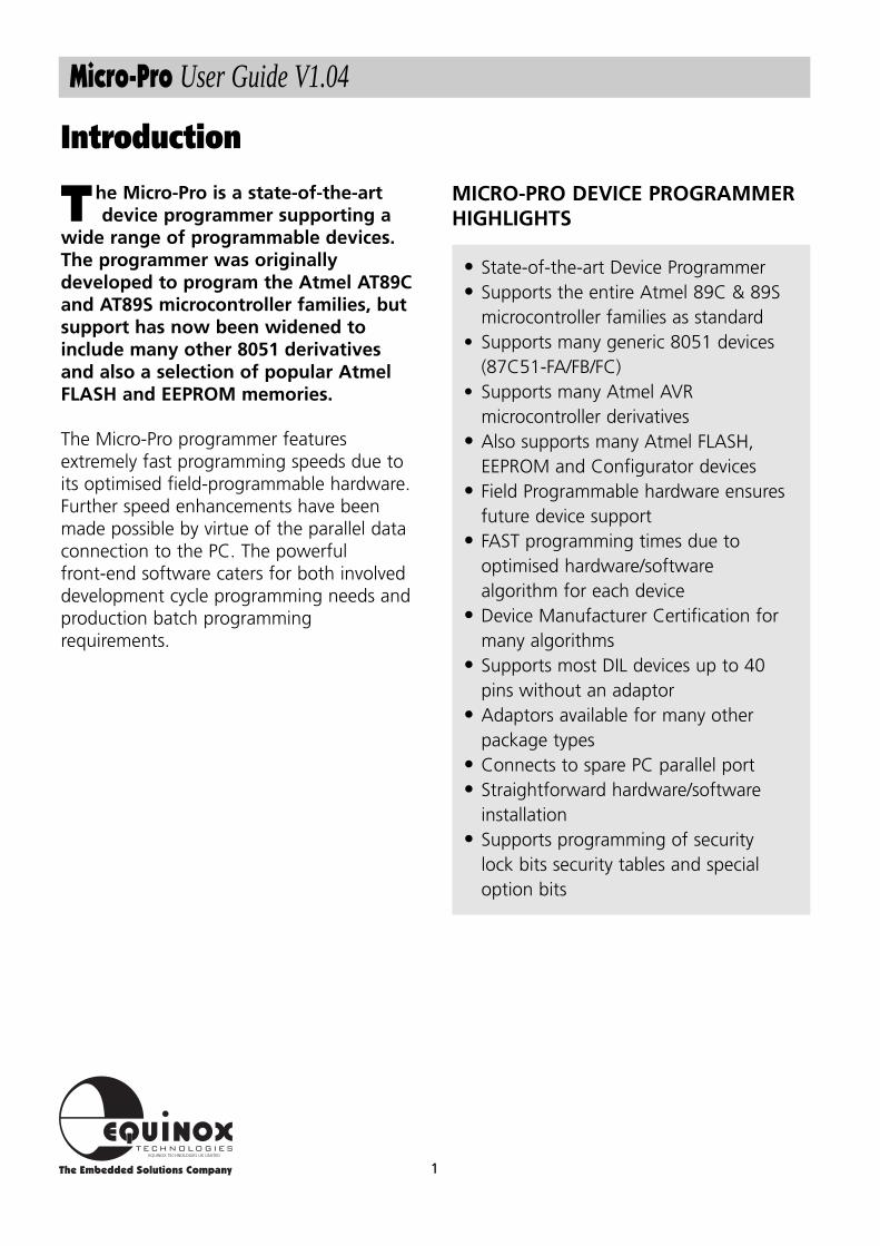
he Micro-Pro is a state-of-the-art device programmer supporting a
wide range of programmable devices.The programmer was originallydeveloped to program the Atmel AT89Cand AT89S microcontroller families, butsupport has now been widened toinclude many other 8051 derivativesand also a selection of popular AtmelFLASH and EEPROM memories.
The Micro-Pro programmer featuresextremely fast programming speeds due toits optimised field-programmable hardware.Further speed enhancements have beenmade possible by virtue of the parallel dataconnection to the PC. The powerfulfront-end software caters for both involveddevelopment cycle programming needs andproduction batch programmingrequirements.
MICRO-PRO DEVICE PROGRAMMERHIGHLIGHTS
• State-of-the-art Device Programmer• Supports the entire Atmel 89C & 89S
microcontroller families as standard• Supports many generic 8051 devices
(87C51-FA/FB/FC)• Supports many Atmel AVR
microcontroller derivatives• Also supports many Atmel FLASH,
EEPROM and Configurator devices• Field Programmable hardware ensures
future device support• FAST programming times due to
optimised hardware/software algorithm for each device
• Device Manufacturer Certification formany algorithms
• Supports most DIL devices up to 40pins without an adaptor
• Adaptors available for many otherpackage types
• Connects to spare PC parallel port• Straightforward hardware/software
installation• Supports programming of security
lock bits security tables and specialoption bits
Introduction
T
2
Micro-Pro User Guide V1.04
System Specifications
MINIMUM SYSTEM CONTENTS
Micro-Pro Device ProgrammerPower Supply (PSU)Parallel Cable (25w M/M pin to pin)
MICRO-PRO PARALLELPROGRAMMER SPECIFICATIONS
Programmer Size : 10.5 x 8 x 2 cmShipped Weight : approx 1.5kgPSU : 15V DC @250mAPort connection : Parallel 25-way DZIF socket : Quality 40way socket
Accepts both 0.3/0.6” pitch devices
MINIMUM PC REQUIREMENTS
The minimum hardware and softwarerequirements to ensure that theprogrammer operates correctly are asfollows:
100% IBM compatible 386+Windows 3.1 or higherMinimum 4MB RAMMinimum 1MB free hard disk spaceSpare PC parallel port
3
Micro-Pro User Guide V1.04
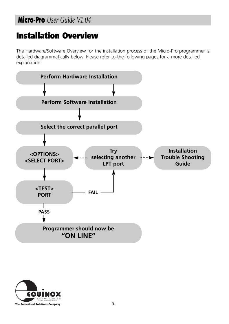
Installation Overview
Perform Hardware Installation
Perform Software Installation
Select the correct parallel port
<OPTIONS><SELECT PORT>
<TEST>PORT
InstallationTrouble Shooting
Guide
Tryselecting another
LPT port
Programmer should now be“ON LINE”
FAIL
PASS
The Hardware/Software Overview for the installation process of the Micro-Pro programmer isdetailed diagrammatically below. Please refer to the following pages for a more detailedexplanation.
4
Micro-Pro User Guide V1.04
Hardware Installation Instructions
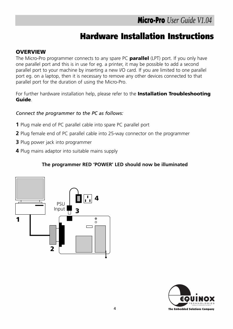
OVERVIEWThe Micro-Pro programmer connects to any spare PC parallel (LPT) port. If you only haveone parallel port and this is in use for eg. a printer, it may be possible to add a secondparallel port to your machine by inserting a new I/O card. If you are limited to one parallelport eg. on a laptop, then it is necessary to remove any other devices connected to thatparallel port for the duration of using the Micro-Pro.
For further hardware installation help, please refer to the Installation TroubleshootingGuide.
Connect the programmer to the PC as follows:
1 Plug male end of PC parallel cable into spare PC parallel port
2 Plug female end of PC parallel cable into 25-way connector on the programmer
3 Plug power jack into programmer
4 Plug mains adaptor into suitable mains supply
The programmer RED ‘POWER’ LED should now be illuminated
1
2
4PSU
Input 3
5
Micro-Pro User Guide V1.04
The Micro-Pro programmer is supplied with'Micro-Pro for Windows' PC driver software.This software is supplied on one 3.5" floppydisk.
TO INSTALL 'MICRO-PRO FORWINDOWS' SOFTWARE:
• Boot the PC into Windows environment(Win 3.1 or Win 95 )
• Insert 'Micro-Pro for Windows' disk intofloppy disk drive (A: / B:)
• Select the 'Run...' command from the'File' menu in the Program Manager
• Select 'Browse' and navigate to the floppydrive (A: / B:)
• Select 'micropro.exe'• Select the 'OK' button
The software installation program shouldnow display an introductory screen. Pleasefollow the on-screen prompts in order tocomplete the software installation process.
For more detailed information on whichlibraries to install, please refer to the ‘DeviceSupport’ section.
On completion, the installation program willinstall the 'Micro-Pro' icon within a newprogram group called 'Micro-Pro'.
To launch the software, simplydouble-click on the'Micro-Pro' icon.
Software Installation
6
Micro-Pro User Guide V1.04
The Micro-Pro programmer plugs into aspare parallel port of any IBM compatiblePC including the majority of laptopmachines.
The programmer should operate correctly inthe following parallel port (LPT) modes:
i. Uni-directional mode
ii. Bi-directional (Enhanced or EPP) mode
However, if the programmer fails to bedetected it is worth switching the LPT modebetween uni and bi-directional using the PCbios and then re-trying the communicationtest.
TO SELECT THE CORRECT PARALLELPORT (LPT):
i. From the menu bar select <Options><Select Port>
The available LPT ports on your computertogether with the corresponding address arenow displayed. eg. LPT1 ($378)
If you have more than one parallel port onyour PC, but only one LPT address isdisplayed, it is likely that your hardwaresetup requires adjusting in the PC bios.
ii. Select the LPT port to which theprogrammer is connected
iii. Select <Test>A programmer communications test is nowperformed.
This tests both the programmer, cable andPC parallel port.
COMMUNICATIONS TEST PASS
The programmer has been detected OK bythe Micro-Pro software. If you now<Cancel> out of the <Test Port> dialoguebox, the words ‘ON LINE’ should now bedisplayed at the bottom right of the Micro-Pro Window.
Installation is complete and the programmershould now be ready to-use.
COMMUNICATIONS TEST FAIL
The programmer was not detected on theLPT port selected. Please check that thecorrect LPT port was selected, and if not,repeat the <Select Port> < Test> operation.
If the programmer is still not detected,please refer to the InstallationTroubleshooting Guide located in the helpfile on disk.
Parallel Port Selection (Select Port)
7
Micro-Pro User Guide V1.04
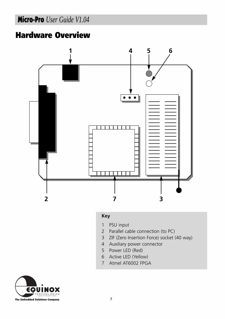
Hardware Overview
1 4 5 6
7 32
Key
1 PSU input2 Parallel cable connection (to PC)3 ZIF (Zero Insertion Force) socket (40 way)4 Auxiliary power connector5 Power LED (Red)6 Active LED (Yellow)7 Atmel AT6002 FPGA
8
Micro-Pro User Guide V1.04
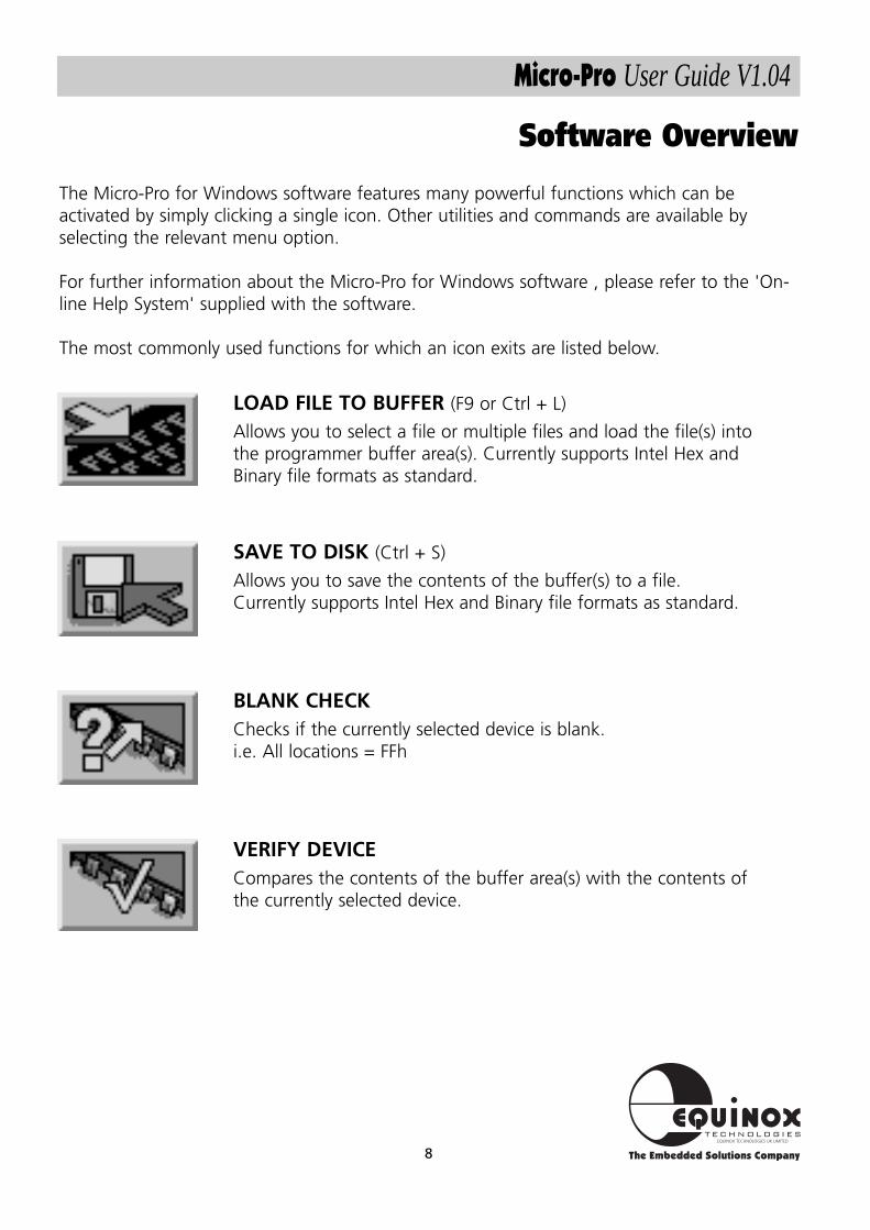
BLANK CHECKChecks if the currently selected device is blank.i.e. All locations = FFh
Software Overview
LOAD FILE TO BUFFER (F9 or Ctrl + L)
Allows you to select a file or multiple files and load the file(s) intothe programmer buffer area(s). Currently supports Intel Hex andBinary file formats as standard.
VERIFY DEVICECompares the contents of the buffer area(s) with the contents ofthe currently selected device.
SAVE TO DISK (Ctrl + S)
Allows you to save the contents of the buffer(s) to a file.Currently supports Intel Hex and Binary file formats as standard.
The Micro-Pro for Windows software features many powerful functions which can beactivated by simply clicking a single icon. Other utilities and commands are available byselecting the relevant menu option.
For further information about the Micro-Pro for Windows software , please refer to the 'On-line Help System' supplied with the software.
The most commonly used functions for which an icon exits are listed below.
9
Micro-Pro User Guide V1.04
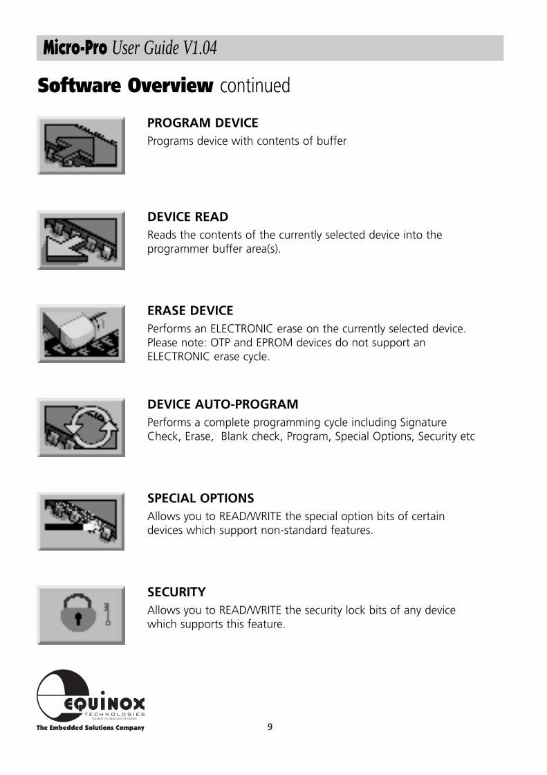
Software Overview continued
DEVICE READReads the contents of the currently selected device into theprogrammer buffer area(s).
PROGRAM DEVICEPrograms device with contents of buffer
SPECIAL OPTIONSAllows you to READ/WRITE the special option bits of certaindevices which support non-standard features.
SECURITYAllows you to READ/WRITE the security lock bits of any devicewhich supports this feature.
DEVICE AUTO-PROGRAMPerforms a complete programming cycle including SignatureCheck, Erase, Blank check, Program, Special Options, Security etc
ERASE DEVICEPerforms an ELECTRONIC erase on the currently selected device.Please note: OTP and EPROM devices do not support anELECTRONIC erase cycle.
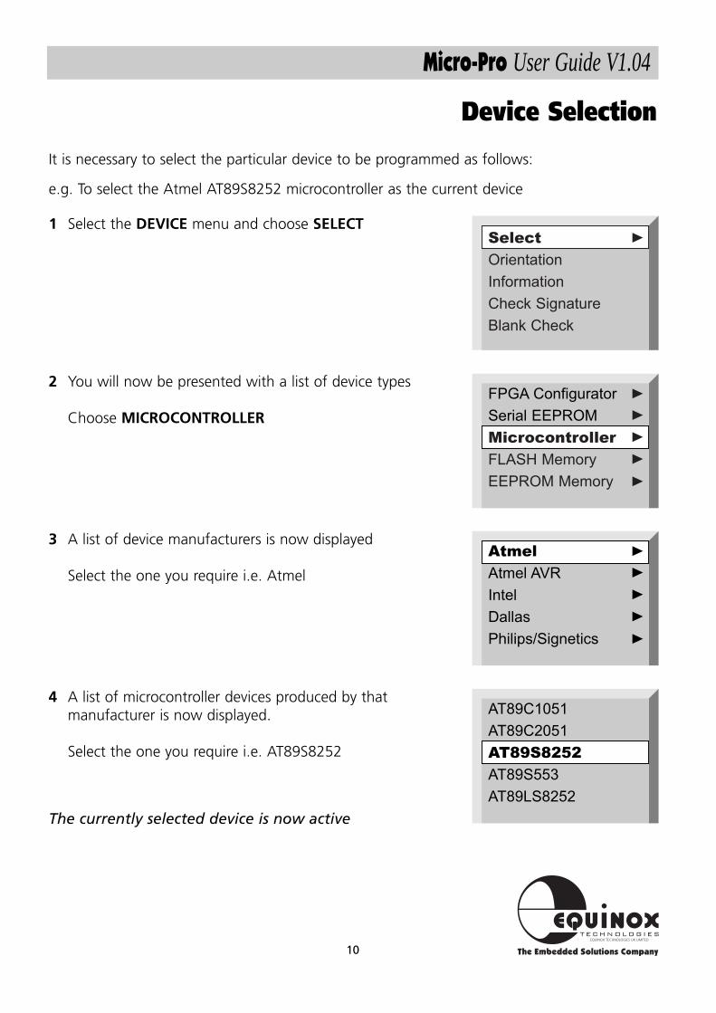
It is necessary to select the particular device to be programmed as follows:
e.g. To select the Atmel AT89S8252 microcontroller as the current device
10
Micro-Pro User Guide V1.04
Device Selection
FPGA Configurator
Serial EEPROM
Microcontroller
FLASH Memory
EEPROM Memory
Select
Orientation
Information
Check Signature
Blank Check
▼▼
▼▼
▼▼
Atmel
Atmel AVR
Intel
Dallas
Philips/Signetics▼
▼▼
▼▼
AT89C1051
AT89C2051
AT89S8252
AT89S553
AT89LS8252
2 You will now be presented with a list of device types
Choose MICROCONTROLLER
1 Select the DEVICE menu and choose SELECT
3 A list of device manufacturers is now displayed
Select the one you require i.e. Atmel
4 A list of microcontroller devices produced by thatmanufacturer is now displayed.
Select the one you require i.e. AT89S8252
The currently selected device is now active
11
Micro-Pro User Guide V1.04
Device Position & Orientation
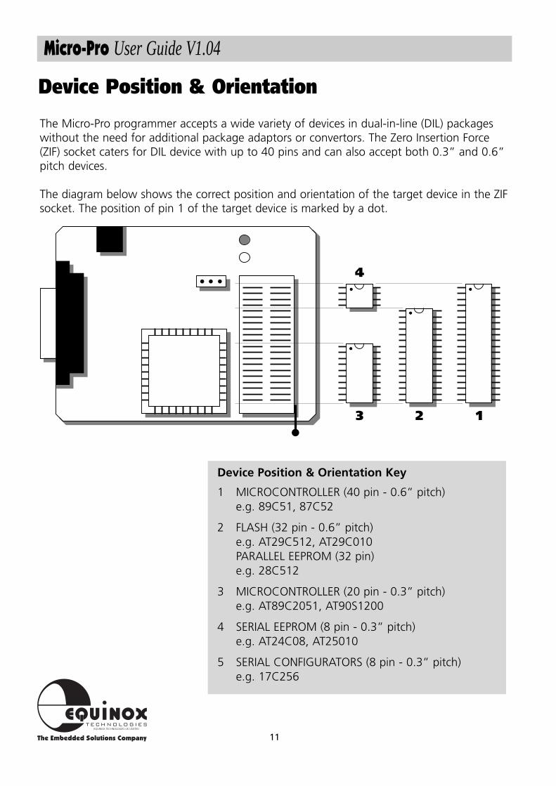
Device Position & Orientation Key
1 MICROCONTROLLER (40 pin - 0.6” pitch) e.g. 89C51, 87C52
2 FLASH (32 pin - 0.6” pitch)e.g. AT29C512, AT29C010 PARALLEL EEPROM (32 pin)e.g. 28C512
3 MICROCONTROLLER (20 pin - 0.3” pitch)e.g. AT89C2051, AT90S1200
4 SERIAL EEPROM (8 pin - 0.3” pitch)e.g. AT24C08, AT25010
5 SERIAL CONFIGURATORS (8 pin - 0.3” pitch)e.g. 17C256
The Micro-Pro programmer accepts a wide variety of devices in dual-in-line (DIL) packageswithout the need for additional package adaptors or convertors. The Zero Insertion Force(ZIF) socket caters for DIL device with up to 40 pins and can also accept both 0.3” and 0.6”pitch devices.
The diagram below shows the correct position and orientation of the target device in the ZIFsocket. The position of pin 1 of the target device is marked by a dot.
3 12
4
12
Micro-Pro User Guide V1.04
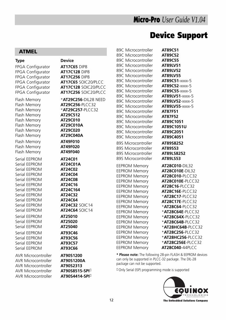
Device Support
ATMEL 89C Microcontroller AT89C5189C Microcontroller AT89C5289C Microcontroller AT89C5589C Microcontroller AT89LV5189C Microcontroller AT89LV5289C Microcontroller AT89LV5589C Microcontroller AT89C51-xxxx-589C Microcontroller AT89C52-xxxx-589C Microcontroller AT89C55-xxxx-589C Microcontroller AT89LV51-xxxx-589C Microcontroller AT89LV52-xxxx-589C Microcontroller AT89LV55-xxxx-589C Microcontroller AT87F5189C Microcontroller AT87F5289C Microcontroller AT89C105189C Microcontroller AT89C1051U89C Microcontroller AT89C205189C Microcontroller AT89C405189S Microcontroller AT89S825289S Microcontroller AT89S5389S Microcontroller AT89LS825289S Microcontroller AT89LS53
EEPROM Memory AT28C010-DIL32EEPROM Memory AT28C010E-DIL32EEPROM Memory AT28C010-PLCC32EEPROM Memory AT28C010E-PLCC32EEPROM Memory AT28C16-PLCC32EEPROM Memory AT28C16E-PLCC32EEPROM Memory *AT28C17-PLCC32EEPROM Memory AT28C17E-PLCC32EEPROM Memory *AT28C64-PLCC32EEPROM Memory *AT28C64E-PLCC32EEPROM Memory *AT28C64X-PLCC32EEPROM Memory *AT28C64B-PLCC32EEPROM Memory *AT28HC64B-PLCC32EEPROM Memory *AT28C256-PLCC32EEPROM Memory *AT28HC256-PLCC32EEPROM Memory *AT28C256E-PLCC32EEPROM Memory AT28C040-44PLCC
Type DeviceFPGA Configurator AT17C65 DIP8FPGA Configurator AT17C128 DIP8FPGA Configurator AT17C256 DIP8FPGA Configurator AT17C65 SOIC20/PLCCFPGA Configurator AT17C128 SOIC20/PLCCFPGA Configurator AT17C256 SOIC20/PLCC
Flash Memory *AT29C256-DIL28 NEEDFlash Memory AT29C256-PLCC32Flash Memory *AT29C257-PLCC32Flash Memory AT29C512Flash Memory AT29C010Flash Memory AT29C010AFlash Memory AT29C020Flash Memory AT29C040AFlash Memory AT49F010Flash Memory AT49F020Flash Memory AT49F040
Serial EEPROM AT24C01Serial EEPROM AT24C01ASerial EEPROM AT24C02Serial EEPROM AT24C04Serial EEPROM AT24C08Serial EEPROM AT24C16Serial EEPROM AT24C164Serial EEPROM AT24C32Serial EEPROM AT24C64Serial EEPROM AT24C32 SOIC14Serial EEPROM AT24C64 SOIC14
Serial EEPROM AT25010Serial EEPROM AT25020Serial EEPROM AT25040Serial EEPROM AT93C46Serial EEPROM AT93C56Serial EEPROM AT93C57 Serial EEPROM AT93C66
AVR Microcontroller AT90S1200AVR Microcontroller AT90S1200AAVR Microcontroller AT90S2313AVR Microcontroller AT90S8515-SPI✝
AVR Microcontroller AT90S4414-SPI✝
* Please note: The following 28-pin FLASH & EEPROM devicescan only be supported in PLCC-32 package. The DIL-28package can not be supported.
✝ Only Serial (ISP) programming mode is supported
13
Micro-Pro User Guide V1.04
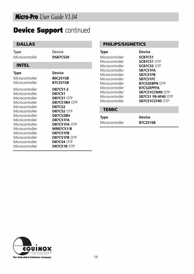
INTEL
Type DeviceMicrocontroller 80C251SBMicrocontroller 87C251SB
Microcontroller D87C51-2Microcontroller D87C51Microcontroller D87C51 OTPMicrocontroller D87C51BH OTPMicrocontroller D87C52Microcontroller D87C52 OTPMicrocontroller D87C52BHMicrocontroller D87C51FAMicrocontroller D87C51FA OTPMicrocontroller MR87C51/BMicrocontroller D87C51FBMicrocontroller D87C51FB OTPMicrocontroller D87C54 OTPMicrocontroller D87C51B OTP
PHILIPS/SIGNETICS
Type DeviceMicrocontroller SC87C51Microcontroller SC87C51 OTPMicrocontroller SC87C52 OTPMicrocontroller S87C51FAMicrocontroller S87C51FBMicrocontroller S87C51FCMicrocontroller 87C52EBPN OTPMicrocontroller 87C52EPFFAMicrocontroller S87C51CCN40 OTPMicrocontroller S87C51 FB-4F40 OTPMicrocontroller S87C51CCF40 OTP
TEMIC
Type DeviceMicrocontroller 87C251SB
Device Support continued
DALLAS
Type DeviceMicrocontroller DS87C520
14
Micro-Pro User Guide V1.04
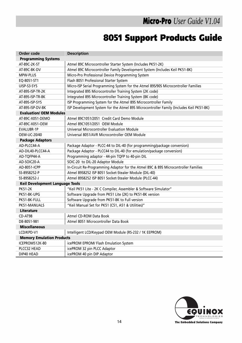
Order code DescriptionProgramming Systems
AT-89C-2K-ST Atmel 89C Microcontroller Starter System (Includes PK51-2K)AT-89C-8K-DV Atmel 89C Microcontroller Family Development System (Includes Keil PK51-8K)MPW-PLUS Micro-Pro Professional Device Programming SystemEQ-8051-ST1 Flash 8051 Professional Starter SystemUISP-S3-SYS Micro-ISP Serial Programming System for the Atmel 89S/90S Microcontroller FamiliesAT-89S-ISP-TR-2K Integrated 89S Microcontroller Training System (2K code)AT-89S-ISP-TR-8K Integrated 89S Microcontroller Training System (8K code)AT-89S-ISP-SYS ISP Programming System for the Atmel 89S Microcontroller FamilyAT-89S-ISP-DV-8K ISP Development System for the Atmel 89S Microcontroller Family (Includes Keil PK51-8K)Evaluation/ OEM Modules
AT-89C-X051-DEMO Atmel 89C1051/2051 Credit Card Demo ModuleAT-89C-X051-OEM Atmel 89C1051/2051 OEM ModuleEVALU8R-1P Universal Microcontroller Evaluation ModuleOEM-UC-20/40 Universal 8051/AVR Microcontroller OEM ModulePackage Adaptors
AD-PLCC44-A Package Adaptor - PLCC-44 to DIL-40 (for programming/package conversion)AD-DIL40-PLCC44-A Package Adaptor - PLCC44 to DIL-40 (for emulation/package conversion)AD-TQFP44-A Programming adaptor - 44-pin TQFP to 40-pin DILAD-SOIC20-A SOIC-20 to DIL-20 Adaptor Module AD-8051-ICPP In-Circuit Re-Programming Adaptor for the Atmel 89C & 89S Microcontroller FamiliesSS-89S8252-P Atmel 89S8252 ISP 8051 Socket-Stealer Module (DIL-40)SS-89S8252-J Atmel 89S8252 ISP 8051 Socket-Stealer Module (PLCC-44)Keil Development Language Tools
PK51-2K “Keil PK51 Lite - 2K C Compiler, Assembler & Software Simulator”PK51-8K-UPG Software Upgrade from PK51 Lite (2K) to PK51-8K versionPK51-8K-FULL Software Upgrade from PK51-8K to Full versionPK51-MANUALS “Keil Manual Set for PK51 (C51, A51 & Utilities)”Literature
CD-AT98 Atmel CD-ROM Data BookDB-8051-981 Atmel 8051 Microcontroller Data BookMiscellaneous
LCD/KPD-V1 Intelligent LCD/Keypad OEM Module (RS-232 / 1K EEPROM)Memory Emulation Products
ICEPROM512K-80 icePROM EPROM/ Flash Emulation SystemPLCC32 HEAD icePROM 32 pin PLCC AdaptorDIP40 HEAD icePROM 40 pin DIP Adaptor
8051 Support Products Guide
15
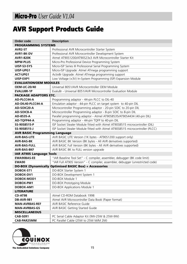
Micro-Pro User Guide V1.04
Order code DescriptionPROGRAMMING SYSTEMSAVR2-ST Professional AVR Microcontroller Starter SystemAVR1-8K-DV Professional AVR Microcontroller Development SystemAVR1-820K Atmel AT90S1200/AT90S23x3 AVR Microcontroller Starter KitMPW-PLUS Micro-Pro Professional Device Programming SystemUISP-S3-SYS Micro-ISP Series III Professional Serial Programming SystemUISP-UPG1 Micro-ISP Upgrade: Atmel ATmega programming supportACT-UPG1 Activ8r Upgrade: Atmel ATmega programming supportUISP-EXP1 Low Voltage (+3V) In-System Programming (ISP) Expansion ModuleEVALUATION/OEM MODULESOEM-UC-20/40 Universal 8051/AVR Microcontroller OEM ModuleEVALU8R-1P Evalu8r - Universal 8051/AVR Microcontroller Evaluation ModulePACKAGE ADAPTORS ETC.AD-PLCC44-A Programming adaptor - 44-pin PLCC to DIL-40AD-DIL40-PLCC44-A Emulation adaptor - 44-pin PLCC on target system to 40-pin DILAD-SOIC20-A Microcontroller Programming adaptor - 20-pin SOIC to 20-pin DILAD-SOIC8-A Microcontroller Programming adaptor - 8-pin SOIC to 8-pin DILAD-8535-A Parallel programming adaptor - Atmel AT90S8535/AT90S4434 (40-pin DIL)AD-TQFP44-A Programming adaptor - 44-pin TQFP to 40-pin DILSS-90S8515-P ISP Socket Stealer Module fitted with Atmel AT90S8515 microcontroller (DIL)SS-90S8515-J ISP Socket Stealer Module fitted with Atmel AT90S8515 microcontroller (PLCC)AVR BASIC Programming LanguageAVR-BAS-LITE AVR BASIC LITE Version (1K bytes - AT90S1200 support only)AVR-BAS-8K AVR BASIC 8K Version (8K bytes - All AVR derivatives supported)AVR-BAS-FULL AVR BASIC Full Version (8K bytes - All AVR derivatives supported)AVR-BAS-8KF AVR BASIC 8K to FULL version upgradeIAR AT90S Language ToolsEWA90BAS-EE “IAR Baseline Tool Set” - C compiler, assembler, debugger (8K code limit)EWA90 “IAR Full AT90S Version” - C compiler, assembler, debugger (unrestricted code)DO-BOX (Dynamically Optimised BASIC Box) + AccessoriesDOBOX-ST1 DO-BOX Starter System 1DOBOX-DV1 DO-BOX Development System 1DOBOX-MOD1 DO-BOX Module 1DOBOX-PM1 DO-BOX Prototyping ModuleDOBOX-AM1 DO-BOX Applications Module 1LITERATURECD-AT98 Atmel CD-ROM Databook 1998DB-AVR-981 Atmel AVR Microcontroller Data Book (Paper format)MAN-AVRBAS-REF AVR BASIC Reference GuideMAN-AVRBAS-GS AVR BASIC Getting Started GuideMISCELLANEOUSCAB-SER1 PC Serial Cable Adaptor Kit (9W-25W & 25W-9W)CAB-PAR25MM PC Parallel Cable (25W to 25W M/M 2M)
AVR Support Products Guide
16
Micro-Pro User Guide V1.04
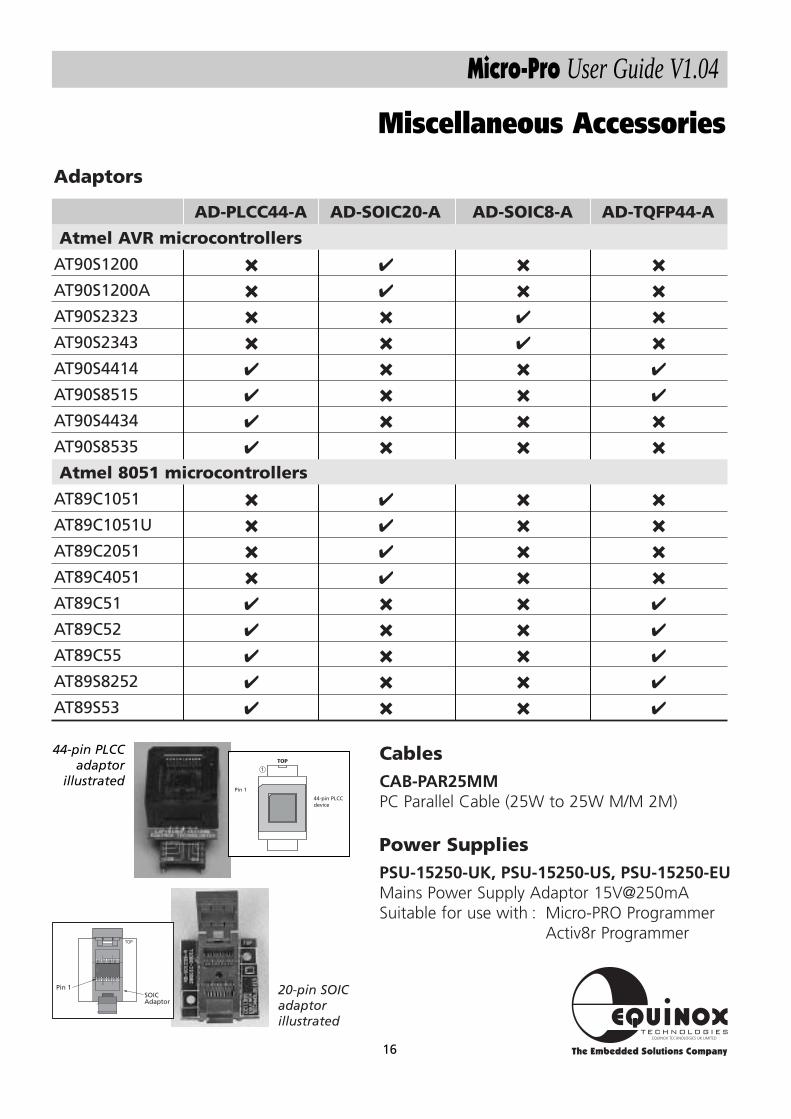
Miscellaneous Accessories
TOP
SOICAdaptor
Pin 1
CablesCAB-PAR25MMPC Parallel Cable (25W to 25W M/M 2M)
Power SuppliesPSU-15250-UK, PSU-15250-US, PSU-15250-EUMains Power Supply Adaptor 15V@250mASuitable for use with : Micro-PRO Programmer
Activ8r Programmer
Adaptors
20-pin SOICadaptorillustrated
AD-PLCC44-A AD-SOIC20-A AD-SOIC8-A AD-TQFP44-A
Atmel AVR microcontrollers
AT90S1200 ✖ ✔ ✖ ✖
AT90S1200A ✖ ✔ ✖ ✖
AT90S2323 ✖ ✖ ✔ ✖
AT90S2343 ✖ ✖ ✔ ✖
AT90S4414 ✔ ✖ ✖ ✔
AT90S8515 ✔ ✖ ✖ ✔
AT90S4434 ✔ ✖ ✖ ✖
AT90S8535 ✔ ✖ ✖ ✖
Atmel 8051 microcontrollers
AT89C1051 ✖ ✔ ✖ ✖
AT89C1051U ✖ ✔ ✖ ✖
AT89C2051 ✖ ✔ ✖ ✖
AT89C4051 ✖ ✔ ✖ ✖
AT89C51 ✔ ✖ ✖ ✔
AT89C52 ✔ ✖ ✖ ✔
AT89C55 ✔ ✖ ✖ ✔
AT89S8252 ✔ ✖ ✖ ✔
AT89S53 ✔ ✖ ✖ ✔
1
TOP
44-pin PLCCdevice
Pin 1
44-pin PLCCadaptor
illustrated

Equinox Technologies UK Limited reserves the right to change any information contained withinthis manual without prior notice. E&OE
Terms and product names contained in this document may be trademarks of others.