Embed Size (px)
Citation preview

PM1100 SERIES
USER MANUAL
Document No :DS8102Issue :CDate :21 December 1995Authorization :1620

Document No: DS8102 Issue: C Page 2
LIMITED WARRANTY
This product is manufactured to exacting standards and the manufacturer warranties that shouldany defect in materials or workmanship occur within the warranty period then it will be repaired or,at the manufacturer's discretion, replaced, free of any charge for labour or materials. This warrantyapplies when the equipment has been used in accordance with the instructions and does not coverfailure due to operator error or use outside design limits.
The manufacturer assumes no responsibility for editorial errors or omissions and for consequentiallosses and/or damages. The information in this document is subject to change without notice.
All brand and product names are trademarks or registered trademarks of their respectivecompanies.

Document No: DS8102 Issue: C Page 3
GENERAL SAFETY POINTS
This equipment has been designed and tested to meet strict international safety requirements,attention to the following general guidelines will ensure it's continued safe operation.
Always connect mains equipment to a properly grounded power socket. The socket must conformto I.E.C. publication 364 "Electrical Installation of Buildings", or the equivalent national standard forexample "15th Edition of I.E.E. Wiring Regulations" in the United Kingdom. If in doubt have thepower socket checked by a qualified electrician.
For protection against electric shock, certain parts of equipment, including the interfaceconnections, are designed such that the voltage is limited to a safe value. In order to maintain thisprotection it is essential that any equipment connected to the printer has interface connections thatare similarly protected.
It is recommended that assurance is obtained from manufacturers / suppliers of such equipmentthat interfaces comply with the requirements of PELV circuits in accordance with BS7002 or SELVcircuits in accordance with I.E.C. 435 edition 2.
In some cases where equipment is supplied with a moulded mains plug which is not compatiblewith local sockets the moulded plug should be cut off and destroyed. MOULDED MAINS PLUGSWHICH HAVE BEEN CUT OFF ARE POTENTIALLY DANGEROUS AND MUST BE DESTROYED.
Unless equipment is designed to be used without an earth, e.g. battery powered or doubleinsulated equipment, the equipment must be earthed.
Always exercise care in moving/positioning equipment.
Always site equipment on a surface suitable for it's weight.
Always use the correct consumables (e.g. paper and ribbons). Use of incorrect consumables willinvalidate the warranty and may result in degraded performance/reduced equipment life.
Do not remove plates, covers or guards that are secured in place by screws or clips. There are nouser serviceable areas within such covers and their removal will invalidate the warranty and maypose a safety risk.
Do not override or defeat mechanical or electrical interlock devices.
Do not allow hair, jewellery or clothing to hang into the equipment (particularly whilst changingconsumables) since this poses a serious safety risk.
Do not operate the equipment if unusual smells or noises are noticed. Turn the equipment off andcontact your supplier for advice.

Document No: DS8102 Issue: C Page 4
C O N T E N T S
INTRODUCTION 6General Description . . . . . . . . . . . . . . . . . . . . . . . . . . . . . . . . . . . . . . . . . . . . . . . . . 6PM1100 Variants . . . . . . . . . . . . . . . . . . . . . . . . . . . . . . . . . . . . . . . . . . . . . . . . . . . . 7
INSTALLATION AND OPERATORS GUIDE 8General . . . . . . . . . . . . . . . . . . . . . . . . . . . . . . . . . . . . . . . . . . . . . . . . . . . . . . . . . . . 8PM1100 Connector and Switch Details . . . . . . . . . . . . . . . . . . . . . . . . . . . . . . . . . . 9Switches . . . . . . . . . . . . . . . . . . . . . . . . . . . . . . . . . . . . . . . . . . . . . . . . . . . . . . . . . 10Power Supply . . . . . . . . . . . . . . . . . . . . . . . . . . . . . . . . . . . . . . . . . . . . . . . . . . . . . 11Paper Loading . . . . . . . . . . . . . . . . . . . . . . . . . . . . . . . . . . . . . . . . . . . . . . . . . . . . . 11Ribbon Replacement . . . . . . . . . . . . . . . . . . . . . . . . . . . . . . . . . . . . . . . . . . . . . . . 11Self Test . . . . . . . . . . . . . . . . . . . . . . . . . . . . . . . . . . . . . . . . . . . . . . . . . . . . . . . . . . 13Loopback Test . . . . . . . . . . . . . . . . . . . . . . . . . . . . . . . . . . . . . . . . . . . . . . . . . . . . . 13Diagnostic Mode . . . . . . . . . . . . . . . . . . . . . . . . . . . . . . . . . . . . . . . . . . . . . . . . . . . 14Default Settings . . . . . . . . . . . . . . . . . . . . . . . . . . . . . . . . . . . . . . . . . . . . . . . . . . . . 14Programme/Setup Mode . . . . . . . . . . . . . . . . . . . . . . . . . . . . . . . . . . . . . . . . . . . . . 15
PROGRAMMING 19Command Summaries . . . . . . . . . . . . . . . . . . . . . . . . . . . . . . . . . . . . . . . . . . . . . . 19
Standard Mode . . . . . . . . . . . . . . . . . . . . . . . . . . . . . . . . . . . . . . . . . . . . 19Epson ESC/POS Emulation . . . . . . . . . . . . . . . . . . . . . . . . . . . . . . . . . . 19Citizen 560 Emulation . . . . . . . . . . . . . . . . . . . . . . . . . . . . . . . . . . . . . . 19
Command Details . . . . . . . . . . . . . . . . . . . . . . . . . . . . . . . . . . . . . . . . . . . . . . . . . . 20Standard Mode . . . . . . . . . . . . . . . . . . . . . . . . . . . . . . . . . . . . . . . . . . . . 20Epson ESC/POS Emulation . . . . . . . . . . . . . . . . . . . . . . . . . . . . . . . . . . 21Citzen 560 Emulation . . . . . . . . . . . . . . . . . . . . . . . . . . . . . . . . . . . . . . . 23
Programming / Operation Notes . . . . . . . . . . . . . . . . . . . . . . . . . . . . . . . . . . . . . . 24Operation . . . . . . . . . . . . . . . . . . . . . . . . . . . . . . . . . . . . . . . . . . . . . . . . 24Power-On Procedure . . . . . . . . . . . . . . . . . . . . . . . . . . . . . . . . . . . . . . . 24General . . . . . . . . . . . . . . . . . . . . . . . . . . . . . . . . . . . . . . . . . . . . . . . . . . 25
CONNECTOR AND TIMING DETAILS 27Serial Connection Details . . . . . . . . . . . . . . . . . . . . . . . . . . . . . . . . . . . . . . . . . . . . 27Parallel Connection Details . . . . . . . . . . . . . . . . . . . . . . . . . . . . . . . . . . . . . . . . . . 27PM1100 Serial Data Timing . . . . . . . . . . . . . . . . . . . . . . . . . . . . . . . . . . . . . . . . . . . 28PM1100 Parallel Data Timing . . . . . . . . . . . . . . . . . . . . . . . . . . . . . . . . . . . . . . . . . 28
CHARACTER SET 30
INTERNATIONAL CHARACTER SETS 31
SUGGESTED POWER SUPPLY CIRCUIT 33
SPECIFICATIONS / FEATURES 35PM1100 . . . . . . . . . . . . . . . . . . . . . . . . . . . . . . . . . . . . . . . . . . . . . . . . . . . . . . . . . . 35

Document No: DS8102 Issue: C Page 5
Ribbon . . . . . . . . . . . . . . . . . . . . . . . . . . . . . . . . . . . . . . . . . . . . . . . . . . . . . . . . . . . 35Paper . . . . . . . . . . . . . . . . . . . . . . . . . . . . . . . . . . . . . . . . . . . . . . . . . . . . . . . . . . . . 35
TROUBLESHOOTING AND MAINTENANCE 37Troubleshooting . . . . . . . . . . . . . . . . . . . . . . . . . . . . . . . . . . . . . . . . . . . . . . . . . . . 38Maintenance . . . . . . . . . . . . . . . . . . . . . . . . . . . . . . . . . . . . . . . . . . . . . . . . . . . . . . 39

Document No: DS8102 Issue: C Page 6
INTRODUCTION
This manual applies to all models of the PM1100 series. Throughout this document the termPM1100 is used generically, any model specific variations are explicitly stated.
General Description
The PM1100 is a compact panel mounted printer available with either serial or Centronics parallelinterfaces. The PM1100 offers the following features
M Easy paper load/ribbon replacement. M Serial RS232/TTL or Centronics Parallel options. M International Character set. M User selectable options stored in non-volatile RAM. M Head jam protection - power to the print head and carriage motor is switched off in the
event of a head jam to prevent damage. M Full 96 ASCII character set (plus additional European and scientific characters). M One line buffer.
M Double width printing.
M Double height printing. M Underlining. M Built-in tab stops. M Vertical tab.
M Form feed.
M Self-test facility. M Inverted Printing. (Data Mode) M Graphics.
M Reset command.
M Software diagnostics.
M Epson ESC/POS and Citizen 560 Emulations.
M Reverse Print.

Document No: DS8102 Issue: C Page 7
A more detailed feature/specification list is contained in Appendix D.

Document No: DS8102 Issue: C Page 8
PM1100 Variants
The PM1100 is available in a number of variants the principle difference between them being themechanism fitted as detailed below:-
PM1101 - M160 Mech - 24 Cols @ 0.7 lines/second.
PM1102 - M163 Mech - 32 Cols @ 0.5 lines/second. PM1103 - M164 Mech - 40 Cols @ 0.4 lines/second.
PM1106 - M180 Mech - 24 Cols @ 1.7 lines/second.
PM1107 - M181 Mech - 30 Cols @ 1.3 lines/second.
PM1108 - M182 Mech - 36 Cols @ 1.1 lines/second.
PM1109 - M183 Mech - 42 Cols @ 1.0 lines/second.
PM1112 - M190 Mech - 24 Cols @ 2.5 lines/second.
PM1114 - M192 Mech - 40 Cols @ 1.7 lines/second.
Additionally the model number indicates the type of data interface as follows:-
PM11XX.5100 Serial (RS232 and TTL) interface
PM11XX.5400 Centronics parallel interface

Document No: DS8102 Issue: C Page 9
Figure 1
PM1100 Panel Mounting
INSTALLATION AND OPERATORS GUIDE
General
The PM1100 is designed to be panel mounted as illustrated in Figure 1. The printer should bepositioned so as to provide easy access to the feed and programme switch and to the paper wellwhen the lid is open. It is recommended that the PM1100 is not sited in an excessively hot or humidlocation. Exposure to grease, dust, metal swarf or liquids is best avoided.

Document No: DS8102 Issue: C Page 10
Figure 2
PM1100 Connector Location
Figure 3
PM1100 Switches
PM1100 Connector and Switch Details
Power and data are supplied via a single 16 way header located on the rear of the printer as shownin Figure 2. Each printer is supplied with a connector with short flying leads suitable for mating withthis header. Please note that conventional IDC ribbon cable and connectors are not generallyconsidered suitable for connection to a PM1100.
The PM1100 switch panel is shown in Figure 3. Full access to the switches is obtained by rotatingthe lid latch as illustrated in Figure 4. It should be noted that the paper feed switch is accessibleeven with the printer cover closed.

Document No: DS8102 Issue: C Page 11
QUARTER TURN
LID CATCH
PAPER FEED
POWER LED
Figure 4
PM1100 Front Panel
Switches
Programme : Press and hold whilst powering on to enter programme mode.Once in programme mode press to cycle through the options forthe selected parameter. When all parameters are set, presssimultaneously with paper feed to exit programme mode.
Feed : Press and hold whilst powering on to initiate self test.
When powered on, press to feed paper.
When in programme mode press to select next parameter.
Indicators
Green : When steady indicates PM1100 on.
When flashing indicates printer in programme mode.

Document No: DS8102 Issue: C Page 12
Power Supply
The PM1100 provides for two separate supply inputs, one for the electronics and one for themechanism. Peak mechanism requirement may reach a momentary maximum of 24A so it isstrongly recommended that separate supplies are employed for the mechanism and electronics toprevent noise spikes affecting the logic. If however the same 5V supply is used to feed theelectronics and the mechanism, then peak mechanism current demands may cause the supplyvoltage to dip below the permitted level for the electronics. If this happens the protection circuitwithin the PM1100 will operate to prevent mechanism damage. Under these circumstances theprinter may stop and restart repeatedly. This type of supply problem can normally be resolved byfitting a reservoir capacitor of around 3300µF on the 5V supply as close as possible to the PM1100.A typical suitable supply circuit is shown in Appendix C.
The PM1100 does not have an integral power switch and it is recommended that in order to ensuresafety and ease of operation a power isolating switch is fitted. Generally such a switch is bestmounted on the panel next to the printer to facilitate ease of self-test and programme/setupoperations.
Paper Loading
The following procedure is recommended for replacing the paper roll. Open the lid to remove anyremaining old paper. Do not to pull the paper backwards out of the rear of the mechanism. Pressthe feed switch until any excess paper left in the mechanism is fed out. Reel off a few centimetresfrom a new paper roll and ensure that the paper end is square.
Sit the paper roll in the paper well with the paper end coming from the bottom of the roll. Offer thepaper into the back of the mechanism and press the feed switch. Keep the switch depressed untilenough paper is fed out for insertion through the paper exit slot. Feed the paper through the exitslot and close the lid. Figure 5 shows the paper path through the printer.
Ribbon Replacement
The recommended procedure for replacement of the printer ribbon is as follows (please refer toFigure 6 ). Open the lid and note that the legend on the cassette gives an instruction (PUSH) toremove the old ribbon. The cassette will clip off one side and can easily be removed. Take a newribbon and check it is taut. Clip it into position making sure that the paper protruding from the topof the mechanism is located between the exposed ribbon and the plastic cassette. Wind the knoba few turns in the direction shown on the cassette to take up any slack in the ribbon. Close the lid.

Document No: DS8102 Issue: C Page 13
Figure 5
Paper Path
Figure 6
Ribbon Replacement
Document No: DS8102 Issue: C Page 14
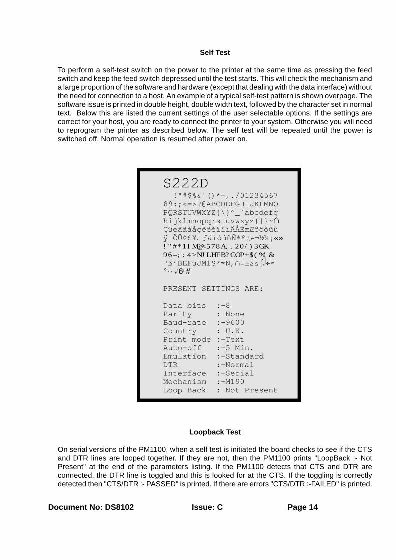
S222D !"#$%&'()*+,./01234567 89:;<=>?@ABCDEFGHIJKLMNO PQRSTUVWXYZ{\}^_`abcdefg hijklmnopqrstuvwxyz{|}~- ÇüéâäàåçêëèïîìÄÅÉæÆôöòûù ÿ ÖÜ¢£¥.ƒáíóúñѪº¿1¬½¼¡«» !"#*1IM@<578A,.20/)3GK 96=;:4>NJLHFB?COP+$(%'& "ß'BEFµJM1S*4N,1/±$#!"÷. E@·%6²# PRESENT SETTINGS ARE:
Data bits :-8 Parity :-None Baud-rate :-9600 Country :-U.K. Print mode :-Text Auto-off :-5 Min. Emulation :-Standard DTR :-Normal Interface :-Serial Mechanism :-M190 Loop-Back :-Not Present
Self Test
To perform a self-test switch on the power to the printer at the same time as pressing the feedswitch and keep the feed switch depressed until the test starts. This will check the mechanism anda large proportion of the software and hardware (except that dealing with the data interface) withoutthe need for connection to a host. An example of a typical self-test pattern is shown overpage. Thesoftware issue is printed in double height, double width text, followed by the character set in normaltext. Below this are listed the current settings of the user selectable options. If the settings arecorrect for your host, you are ready to connect the printer to your system. Otherwise you will needto reprogram the printer as described below. The self test will be repeated until the power isswitched off. Normal operation is resumed after power on.
Loopback Test
On serial versions of the PM1100, when a self test is initiated the board checks to see if the CTSand DTR lines are looped together. If they are not, then the PM1100 prints "LoopBack :- NotPresent" at the end of the parameters listing. If the PM1100 detects that CTS and DTR areconnected, the DTR line is toggled and this is looked for at the CTS. If the toggling is correctlydetected then "CTS/DTR :- PASSED" is printed. If there are errors "CTS/DTR :-FAILED" is printed.

Document No: DS8102 Issue: C Page 15
If this test is completed the PM1100 checks for a link between RX and TX and attempts to senda short ASCII string over the link. If the ASCII string is successfully received the EM1100 prints"RX/TX :- PASSED". Otherwise it prints "RX/TX :- FAILED".
This test provides a means for checking the connection of the PM1100 to external equipment byverifying the operation of the line drivers/receivers used on the data interface.
Diagnostic Mode
Diagnostic Mode reveals control codes and characters sent to the printer. Characters 00H to 1FHare translated to characters 40H to 5FH and underlined to indicate a control character. To enterdiagnostic mode initiate self-test and keep the feed switch depressed until 'DIAGNOSTIC MODE'is printed following one complete self test cycle. The power-on indicator will flash every twoseconds whilst in this mode.
An example of diagnostic mode is as follows :
ABC DE F ...Normal Print
ABCIDE FM ...Diagnostic Print Out
In the example the following sequence of characters was sent:
Characters ABC, horizontal tab (I), characters DE, space, character F, carriage return (M).
A list of valid control characters is shown on page 11.
To terminate diagnostic mode switch off and power- on again to resume normal operation.
Default Settings
The PM1100 printer is supplied with the following default settings:
Data bits 8Parity None (Not shown for Parallel Interface)Baud Rate 9600 (Not shown for Parallel Interface)Character Set UKPrint Mode TextAuto-Off Not Applicable for Panel MountEmulation StandardDTR NormalInterface Serial or ParallelMechanism As applicable (Automatically detected and set by the printer)

Document No: DS8102 Issue: C Page 16
Programme/Setup Mode
On the front of the unit there is a power on indicator and a paper feed switch. Opening the lid willreveal the programme switch situated next to the feed switch.
If the programme (set-up) switch is pressed at power up (i.e. programme switch and power-onswitch together) then the printer will go into set-up mode and print the current parameter status. Example : Number of data bits : 8 bit data.
The power-on indicator will flash every second to indicate programme mode. Each time the feed switch is pressed and released the next printer parameter is printed. Pressingthe programme switch will cause the status of that parameter to change in the sequence shown.Each status table rotates so 300 baud follows on from 19200 baud and so on.
Once the correct status has been selected then both the programme switch and the feed switchshould be pressed simultaneously to update the printer’s status. Note that this need only be donewhen all parameters that need changing have been selected. If no switches are pressed for 15seconds the set-up mode is automatically terminated without changing the original parameters.

Document No: DS8102 Issue: C Page 17
Parameter (FEED Switch) Status (PROGRAMME Switch)
(1) Number of data bits 8 bit data7 bit data
(2) * Serial Parity No parityOdd parityEven parity
(3) * Serial Baud Rate 300 baud600 baud1200 baud2400 baud4800 baud9600 baud19200 baud
(4) Character Set USA ITALYFRANCE SPAING E R M A N Y
JAPANENGLAND NORWAYDENMARK IDENMARK IISWEDEN
(5) Print Mode TEXT (Normal Print)DATA (Inverted Print)
(6) Auto POWER OFF 5 minutes1 minuteDisabled
(7) Emulation StandardCitizen 560ESC/POS
(8) DTR NormalInverted
* NOTE : Not printed for a parallel interface
An alternative method is to send the "set up" data via the RS232 port to prevent the needfor manual programming.

Document No: DS8102 Issue: C Page 18
Setup via Data Interface
If the PM1100 is turned on whilst both the programme and feed switches are pressed and only theprogramme switch is released, the PM1100 will print:-
"NVR COMMS READY>"
At this point the printer is waiting to receive data in the following format:-
"PROGRAMME-MODE" + CARRIAGE RETURN + n1 + ....n10 (n1 to n10 are hex numbers)
The "PROGRAMME-MODE" followed by a carriage return indicates that the printer should expectparameter data as shown in Table 1 below.
Note: The data sent to reprogramme the printer is always expected at 9600 baud, 8 data bits,no parity, irrespective of any of the existing printer settings.
Upon receiving information in the correct format the PM1100 will print:-
"DATA OK, NVR UPDATED!"
If the data received is not in the correct format then the PM1100 will print:-
"DATA ERROR NVR UNCHANGED"
Note: If no data is received within 15 seconds or the feed key is released before the procedureis complete, then the change of parameters will not take place and the PM1100 will print:-
"SET ERROR NVR UNCHANGED"
TABLE 1
Value 6 0 1 2 3 4 5 6 7 8 9 10
n Description 9
1 Data Bits 7 8
2 Parity Even Odd None
3 Baud Rate 19200 9600 4800 2400 1200 600 300
4 Country Denmark 2 Norway Japan Spain Italy Sweden Denmark 1 U.K. Germany France U.S.A.
5 Print Mode Data Text
6 Auto Off Disabled 1 Minute 5 Minute
7 Emulation ESCPOS 560 Standard
8 DTR Inverted Normal
9 Zero Status O i
10 Reserved for future use - A zero value must be sent with present firmware
String "PROGRAMME-MODE", 0DH,n1,n2,n3,n4,n5,n6,n7,n8,n9,n10

Document No: DS8102 Issue: C Page 19
SAMPLE PROGRAMME IN BASIC
10 KEY OFF:CLS:15 LOCATE 2,25:PRINT "NVR TEST ROUTINE FOR PM1100";16 LOCATE 3,25:PRINT "-------------------------";20 LOCATE 5,25:INPUT "(S)erial or (P)arallel ?",A$30 IF A$="S" OR A$= "s" THEN 6040 IF A$="P" OR A$= "p" THEN 5045 GOTO 1050 WIDTH "lpt1:",255:OPEN "lpt1:" AS #1:GOTO 6560 OPEN "COM1:9600,N,8,1,RS,CSO,DS65535" AS #165 LOCATE 7,5:INPUT "Press prog+feed, power on, release prog on PM1100, then
pressany key ...";B$
70 PRINT #1,"PROGRAMME-MODE";CHR$(13);80 FOR I=1 TO 10:READ A:PRINT #1,CHR$(A);:NEXT I90 RESTORE100 PRINT #1,CHR$(13);CHR$(13)110 CLOSE #1120 DATA 0,1,2,9,0,1,1,1,1,0
The programme sets: 7 data, odd parity, 4800 baud, France, Data mode, 1 min., 560,NORMAL DTR, zero with a "slash" across it.
Note that the factory defaults can always be restored by pressing both the feed andprogramme switches at power up then releasing only the Feed switch. Defaults will berestored and a printed message acknowledges that this has occurred.

Document No: DS8102 Issue: C Page 20
PROGRAMMING
Command Summaries
Standard Mode
Function Keystroke Hex DecimalHorizontal Tab CTRL I 09H 9Line Feed CTRL J 0AH 10Form Feed CTRL K 0BH 11 Vertical Tab CTRL L, n 0CH, n 12,nCarriage Return CTRL M 0DH 13Double Width CTRL N 0EH 14Single Width CTRL O 0FH 15Reset CTRL Q 11H 17Underline CTRL U 15H 21Underline Release CTRL X 18H 24Reverse Print CTRL Y 19H 25Double Height CTRL Z 1AH 26Graphics CTRL [, n 1BH, n 2 7 , n
Epson ESC/POS Emulation
Function Keystroke Hex DecimalHorizontal Tab CTRL I 09H 9Line Feed CTRL J 0AH 10Form Feed CTRL L 0CH 12Carriage Return CTRL M 0DH 13Set Print Mode ESC ! n 1BH, 21H, n 27,33,nInitialise Printer ESC @ 1BH, 40H 27,64Character Set ESC R n 1BH, 52H, n 27,82,nPrint & Feed ESC d n 1BH, 64H, n 27,100,nStatus Request ESC v 1BH, 76H 27,118Inverted Printing ESC { n 1BH, 7BH, n 27,123,nSet form length ESC C n 1BH, 43H, n 27,67,n
Citizen 560 Emulation
Function Keystroke Hex DecimalLine Feed CTRL J 0AH 10Form Feed CTRL L 0CH 12Carriage Return CTRL M 0DH 13Reverse Print CTRL T 14H 20Clear Buffer CTRL X 18H 24 Graphic Print ESC K 1BH, 4BH 27,75 Page length/format ESC C 1BH, 43H 2 7 , 6 7 acknowledged Paging Is Off ESC O 1BH, 4FH 27,79 but not2.75 mm Spacing ESC 1 1BH, 31H 27,49 executed.5.5 mm Spacing ESC 2 1BH, 32H 27,50 Double Width - 1EH 30

Document No: DS8102 Issue: C Page 21
Single Width - 1FH 31

Document No: DS8102 Issue: C Page 22
Command Details
Standard Mode
TAB (09H) Tab stops occur at every 8th column. On receipt of thiscommand, spaces are entered into the line up to the nexttap stop.
LINE FEED (0AH) Prints current line and feeds one line. If LF, CR is sent,the CR is ignored to avoid a double feed.
FORM FEED (0BH) Will feed 4 fast line feeds.
VERTICAL TAB (0CH,n) Fast feeds the paper by n lines. n is a single byte hexnumber in the range 0 < n < 20H. Note that a vertical tabwill print the contents of the line buffer before beingexecuted.
CR (0DH) Prints current line and feeds one line. If CR and LF is
sent the LF is ignored to avoid a double feed.
On the receipt of the last printable character (e.g. 24characters for M190), the printer will automatically printthe data in the buffer. If CR and LF are sent after thiscondition they will be ignored.
DOUBLE WIDTH (0EH) Turns double width printing on. This state continues untilterminated by the single width command or completionof the current line.
If the last character in the line buffer is double width butthere is only room for a single width character, then it willbe printed in single width.
SINGLE WIDTH (0FH) Reverts to single width printing. Single and double width
can be combined anywhere on a line. RESET (11H) Causes printer status reset. Printer status is set to single
width, normal height, no underline. Note that the bufferremains unaltered to avoid any data loss.
UNDERLINE (15H) Characters sent after this command will be underlined.Tabs are not underlined. Underlining is terminated by theU/L release command or on completion of the currentline.
U/L RELEASE (18H) Terminates underlining.
REVERSE PRINT(19H) This command sets the print to white on black. Thecommand will toggle between reverse and normal print

Document No: DS8102 Issue: C Page 23
wherever it appears on a line but the condition is alwaysreset at the end of the line.
DOUBLE HEIGHT (1AH) Prints the line in double height for one line only. Double
height and single height cannot be mixed on the sameline.
GRAPHICS (1BH,n) Graphics command to enter bit image printing. Thenumber of graphic bytes sent will depend on the type ofmech. (e.g. 24 for M190, 40 for M192). For each graphicbyte sent, 6 bits out of the 8 bits are used to build thegraphics string (LSB as the right most dot). 'n' is thenumber of times the string sent will be repeated for arepetitive pattern. 'n' is limited to a maximum of 255lines. The print buffer will be printed first if not empty.
Examples:
To repeat a string of data bytes,d1....d24 over two rows for an M190mechanism send : 1BH, 02H, d1....d24.
For a non-repeated string send : 1BH,01H, d1....d24.
Epson ESC/POS Emulation
TAB (09H) Tab stops occur at every 8th column. On receipt of thiscommand, spaces are entered into the line up to the nexttap stop.
LINE FEED (0AH) Prints the current line and feeds one line. If LF,CR issent the CR is ignored to avoid a double feed.
FORM FEED (0CH) Prints the current line and feeds the number of linesdetermined by using the ESC C command.
CR (0DH) Prints current line and feeds one line. If CR and LF aresent the LF is ignored to avoid a double feed.
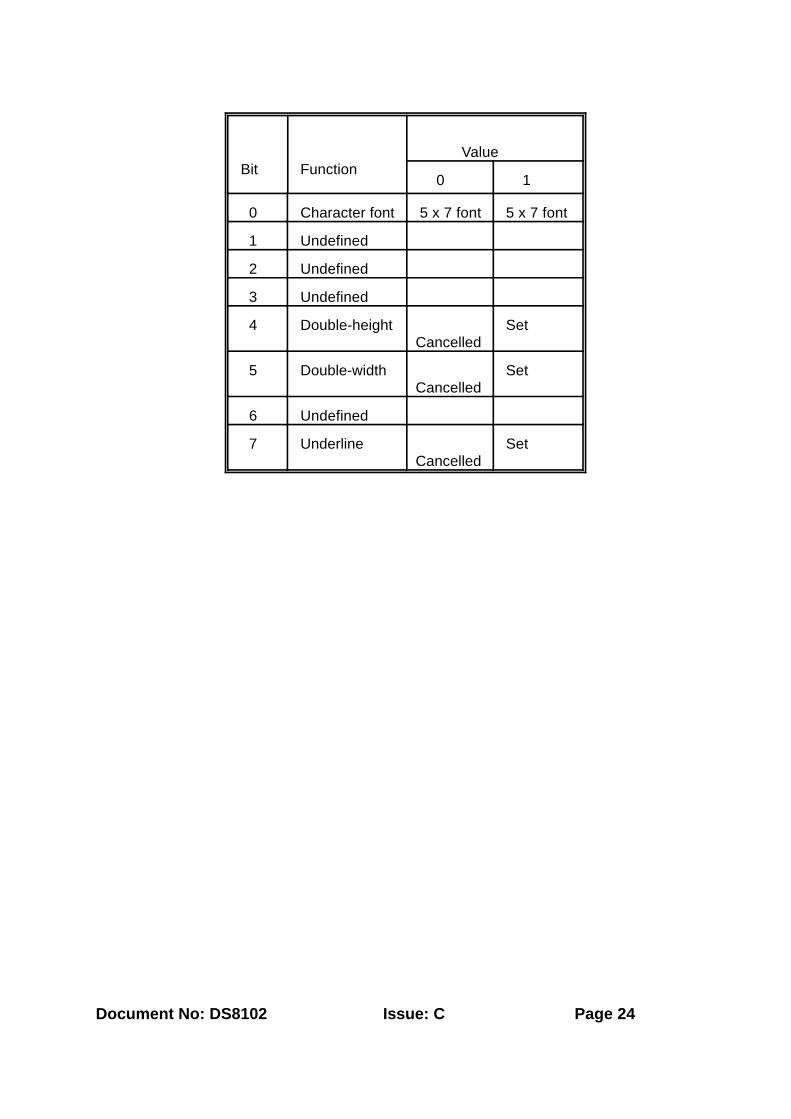
ESC ! n (1BH,21H,n) Sets the print mode according to the following table. n isa single byte in which each bit sets the printing function.Note that underlines cannot be used with a horizontal taband any combination of double height and width can beused. Default is n = 0.
Document No: DS8102 Issue: C Page 24
Bit
Function
Value
0 1
0 Character font 5 x 7 font 5 x 7 font
1 Undefined
2 Undefined
3 Undefined
4 Double-heightCancelled
Set
5 Double-widthCancelled
Set
6 Undefined
7 UnderlineCancelled
Set

Document No: DS8102 Issue: C Page 25
ESC@(1BH,40H) Initialise printer. Clears the print buffer and resets theprinter mode to default values.
ESC R n (1BH,52H,n) Selects international character set from the followingtable determined by the value of n. The default value isthe character set programmed in the printer.
n Country
0 U.S.A.
1 France
2 Germany
3 U.K.
4 Denmark 1
5 Sweden
6 Italy
7 Spain
8 Japan
9 Norway
10 Denmark 11
ESC d n (1B,64H,n) Prints the data in the print buffer and performs n linefeeds.
ESC v (1BH,76H) Status request. The current printer status is transmittedto the host computer on receipt of this command. It takesthe form of a single byte which is fixed at 0 (to indicatepaper in). The byte is sent regardless of the CTShandshaking signal.
ESC { n (1BH,7BH,n) Inverted print command. When n = 1 then print isinverted and text will be printed from right to left. Fornormal print n = 0. The default mode is set by theprogrammed parameters in the printer.
ESC C n (1BH,43H,n) Set form length. When used in conjunction with the formfeed command (0CH), the printer will feed n lines. Notethat if n = 0 then there will be no line feeds.
Citzen 560 Emulation
LINE FEED (0AH) Feeds a new line after printing.

Document No: DS8102 Issue: C Page 26
FORM FEED (0CH) Carries out a form feed performance after printing. Thisfunction is fixed to three lines.
CR (0DH) Feeds a new line after printing.
REVERSE PRINT (14H) This command sets the print to white on black. Thecommand will toggle between reverse and normal printwherever it appears on a line but the condition is alwaysreset at the end of the line.
CLEAR BUFFER (18H) Clears the print data in the buffer. All the previous inputdata is cleared with this code. However, in case ofgraphic print mode, this code is treated as data.
DOUBLE WIDTH (1EH) Enhanced character designation. The designation isreleased with US code (1FH) or line feed (0AH).Standard and enhanced characters can be printed inone line.
SINGLE WIDTH (1FH) Standard character designation. Initiated after power upand after each printed line.
ESC K n1, n2, (1BH,4BH n1, n2) This command requires special note because allassociated data will be ignored. The number of graphicsbytes determined by n1 and n2, will be received butdiscarded so as not to appear as erroneous text.
Programming / Operation Notes
Operation
DO read the operating instructions carefully before you attempt to use the printer.
DO ensure that any electrical connections are properly made in accordance with theinstructions.
DO NOT remove any fixed covers unless you are qualified to do so - and even then switchoff first and disconnect the power adaptor from the socket before you start.
DO NOT continue to operate the printer if you have any doubt about it working normally,or if it is damaged in any way. Refer the unit for repair.
Power-On Procedure
Check that the power applied to the unit is correct.
Open the lid and check that paper and ribbon are present and that there are no foreignobjects inside the paper well or mechanism.
Close the lid, ensuring the paper is guided out through the paper exit slot.

Document No: DS8102 Issue: C Page 27
Switch on the power to the printer.
The power-on indicator will light, the mechanism head will briefly shuttle from side to sideand the interface busy signal will clear. If this does not happen refer to Appendix E.
NOTE : There is no power on/off switch on the printer.
General
Do not remove paper by pulling it from the back of the mechanism and do not pull excessivelengths through the top of the mechanism. Either of these operations may cause paper totear and jam the mechanism.

Document No: DS8102 Issue: C Page 28
APPENDIX A
Connector and Timing Details

Document No: DS8102 Issue: C Page 29
PM1100 Connector Details
CONNECTOR AND TIMING DETAILS
Serial Connection Details
12 DTR3456 MECHANISM GROUND78 ELECTRONICS GROUND910 MECHANISM SUPPLY1112 ELECTRONICS SUPPLY13141516 RECEIVED DATA
Parallel Connection Details
1 DATA 72 BUSY3 DATA 64 ACK *5 DATA 56 MECHANISM GROUND7 DATA 48 ELECTRONICS GROUND9 DATA 310 MECHANISM SUPPLY11 DATA 212 ELECTRONICS SUPPLY13 DATA 11415 DATA 016 STROBE *

Document No: DS8102 Issue: C Page 30

Document No: DS8102 Issue: C Page 31
DATA
STROBE
BUSY
ACKNOWLEDGE
Min 1µS
Max 1µS
Min 0.25µS
Min 2µSMax 500µS
Min 5µSMax 500µS
PM1100 Serial Data Timing
Note : Mark Voltage level is +5V for TTL data and <-5V for RS232 Data
PM1100 Parallel Data Timing

Document No: DS8102 Issue: C Page 32
APPENDIX B
Character Set Details

Document No: DS8102 Issue: C Page 33
0 1 2 3 4 5 6 7 8 9 A B C D E F
0 SP 0 @ P ` p Ç É á ! . J " /
1 ! 1 A Q a q ü æ í " 2 L ß ±
2 " 2 B R b r é Æ ó # 0 H ' $
3 # 3 C S c s â ô ú * / F B #
4 DC4 $ 4 D T d t ä ö ñ 1 ) B E !5 % 5 E U e u à ò Ñ I 3 ? F "6 & 6 F V f v å û ª M G C µ ÷
7 ' 7 G W g w ç ù º D K O J .
8 ( 8 H X h x ê ÿ ¿ @ 9 P M E
9 CAN ) 9 I Y i y ë Ö 1 < 6 - 1 @
A LF * : J Z j z è Ü ¬ 5 = + S ·
B ESC
+ ; K [ k { ï ¢ ½ 7 ; $ * %C FF , < L \ l | î £ ¼ 8 : ( 4 6
D CR - = M ] m } ì ¥ ¡ E 4 % N ²
E S0 . > N ^ n ~ Ä . « A > ' , #
F / ? O _ o SP Å ƒ » , N & 1 SP
CHARACTER SET
SP indicates a space character. Blank locations indicate unused codes.

Document No: DS8102 Issue: C Page 34
n 35D
23H
36D
24H
64D
40H
91D
5BH
92D
5CH
93D
5DH
94D
5EH
96D
60H
123D
7BH
124D
7CH
125D
7DH
126D
7EH
U.S.A. 0 # $ @ [ \ ] ^ ` { | } ~
FRANCE 1 # $ à E ç § ^ ` é ù è "
GERMANY 2 # $ § Ä Ö Ü ^ ` ä ö ü ß
U.K. 3 £ $ @ [ \ ] ^ ` { | } ~
DENMARK I 4 # $ @ Æ Ø Å ^ ` æ ø å ~
SWEDEN 5 # ¤ É Ä Ö Å Ü é ä ö å ü
ITALY 6 # $ @ E \ é ^ ù à ò è i
SPAIN 7 . $ @ i Ñ ¿ ^ ` " ñ } ~
JAPAN 8 # $ @ [ ¥ ] ^ ` { | } ~
NORWAY 9 # ¤ É Æ Ø Å Ü é æ ø å ü
DENMARK II 10 # $ É Æ Ø Å Ü é æ ø å ü
INTERNATIONAL CHARACTER SETS

Document No: DS8102 Issue: C Page 35
APPENDIX C
Suggested Power Supply Circuit

Document No: DS8102 Issue: C Page 36
SUGGESTED POWER SUPPLY CIRCUIT
The circuit shown below is suitable for powering the PM1100 family of printers

Document No: DS8102 Issue: C Page 37

Document No: DS8102 Issue: C Page 38
APPENDIX D
Specifications and Features

Document No: DS8102 Issue: C Page 39
SPECIFICATIONS / FEATURES
PM1100
Power Supply : A supply of 5V d.c. at 3A(mean), 6A(peak) issufficient to power the printer. On load terminal voltage must be limited to 5V±5%.
Mechanism : EPSON M160/180/190 impact printer series. Character Set : Full international character sets plus additional
European and scientific characters. (SeeAppendix B).
Character Matrix : 5 X 7 dots.
Buffer : 1 character line. Graphics : Refer to mechanism specifications.
Line Pitch : " " " "
Print Speed : " " " "
Reliability : " " " "
Interface : Centronics Parallel or RS232/TTL Serial.
Consumables : Ribbon Cassette : IRC160PUPaper : OP58
Environment : Operating Temperature 0 to 40 deg C.Storage Temperature -25 to 40 deg C.Operating Humidity 10% to 85% (Non-Condensing). Storage Humidity 10% to 90% RH (Non-Condensing).
Dimensions : 109(±0.5)x mm x 62.0 (±0.5) mm
Ribbon
Standard Purple ink (250,000 characters)IRC160PU
Standard Black ink (200,000 characters)IRC160BK
Long Life Purple ink (1,000,000 characters) IRC180PU
Paper

Document No: DS8102 Issue: C Page 40
The PM1100 uses wood free white paper to the following specification.
Dimensions : 57.5mm ± 0.5mm (width)57mm max (Roll diameter)
Thickness : 85 microns

Document No: DS8102 Issue: C Page 41
APPENDIX E
TROUBLESHOOTING ANDMAINTENANCE

Document No: DS8102 Issue: C Page 42
TROUBLESHOOTING AND MAINTENANCE
Troubleshooting
The majority of problems associated with PM1100's can be traced to improper installation,cabling or setup. The following notes should assist in identifying and correcting some of themore common problems. If additional assistance is required please contact your supplier.
(1) The power light does not come on when the unit is switched on.
Check that the power applied to the unit is correct. If power resource is satisfactory and theLED still does not illuminate when the power is switched on, refer the unit for repair.
(2) Power light comes on but does not feed paper.
This is a head jam condition. Check that there is no paper jammed in the mechanism.
(3) Power light comes on but flickers when printing or feeding paper.
Check rating of power source. (see page 6).
(4) Printer only prints rows of dots
Check rating of power source. (see page 6).
(5) Printer prints short lines of text but will not print full lines.
Check rating of power source. (see page 6).
(6) The paper is not feeding properly.
If the print looks squashed, check that the paper roll is sitting correctly in the paper well andthat the roll is the right way up. The paper should be feeding off the bottom of the roll intothe back of the mechanism. NOT off the top of the roll. Remove paper and reload ifnecessary. (7) No print on paper.
If the printer is working but no print is visible, check that the ribbon is present and notexcessively worn and that it is freely moving round the cartridge. Wind the ribbon onmanually then feed paper while the lid is open to check the cassette knob is rotating. Alsocheck that the ribbon has been fitted correctly and that the exposed ribbon is in front of thepaper.
(8) Printer does self-test but does not print data sent through interface.
Check interface connections are correct.
(9) The printer prints r in place of the transmitted characters or it does not actioncommands.

Document No: DS8102 Issue: C Page 43
This indicates a communications error between host and printer. Check handshaking lineor parity setting.

Document No: DS8102 Issue: C Page 44
(10) If a command is not carried out by the printer, it is possible to check for an incorrectcontrol code or character by initiating diagnostic Mode.
EXAMPLE : HORIZONTAL TAB (09H) = CTRL I Printed as ICARRIAGE RETURN (0DH) = CTRL M Printed as M
Normal characters are not underlined.
Maintenance
Periodic cleaning will help to keep your printer in good condition.
IMPORTANT : Switch the power to the printer off and disconnect the power supply beforeany cleaning operation.
Use a soft brush to remove any dust or foreign particles from the paper well andmechanism. The case may be cleaned with a soft cloth lightly dampened with alcohol. Becareful not to let any liquid enter the printer enclosure.
Do not use the printer if liquid or metal objects have entered the unit. If this happens whilstthe printer is in use, switch off immediately and have it serviced.
If the printer is not going to be used for some time disconnect the power adaptor andensure the unit is switched off.
Do not continue printing with a worn ribbon, since this will eventually fray and may damagethe print head.
Do not leave the printer powered up if it is malfunctioning.