Embed Size (px)
Citation preview

For support mail to: [email protected]
See also our website: www.smac-mca.com
www.ingeniamc.com
Embedded Motion
Control Library
Product Manual
Revision 1.3 (Firmware version 2.0)

Embedded Motion Control Library –
Product manual
Copyright and trademarks
Copyright © 2013 INGENIA-CAT, S.L.
Scope
This document applies to all i116 controllers based on emcl library version 2.0.
Disclaimers and limitations of liability
Except in cases specifically indicated in other agreements and INGENIA-CAT, this
product and its documentation are provided “as is”, with no warranties or conditions of
any type, whether express or implied, including, but not limited to the implied
warranties or conditions of merchantability, fitness for a particular purpose or non-
infringement.
INGENIA-CAT rejects all liability for errors or omissions in the information or the
product or in other documents mentioned in this document.
INGENIA-CAT shall in no event be liable for any incidental, accidental, indirect or
consequential damages (including but not limited to those resulting from: (1)
dependency of equipment presented, (2) costs or substituting goods, (3) impossibility of
use, loss of profit or data, (4) delays or interruptions to business operations (5) and any
other theoretical liability that may arise as a consequence of the use or performance of
information, irrespective of whether INGENIA-CAT has been notified that said damage
may occur.
Some countries do not allow the limitation or exclusion of liability for accidental or
consequential damages, meaning that the limits or exclusions stated above may not be
valid in some cases.
This document may contain technical or other types of inaccuracies. This information
changes periodically.

3
Contents
Functional overview .............................................................................................. 6
1.1 What is a motion controller? ....................................................................... 6
1.2 Applicability .................................................................................................. 6
1.3 What is emcl? ................................................................................................ 7
1.4 Motor controllers based on emcl ................................................................. 7
1.4.1 Functional block diagram ..................................................................... 7
1.4.2 Signaling of the system ......................................................................... 8
1.4.3 Controller structure ............................................................................... 8
1.4.4 Object structure ...................................................................................... 9
Communications .................................................................................................. 11
2.1 Introduction ................................................................................................. 11
2.2 CANopen ..................................................................................................... 11
2.2.1 Introduction .......................................................................................... 11
2.2.2 CANopen message format .................................................................. 12
2.2.3 Communications objects ..................................................................... 14
2.3 RS232 ............................................................................................................ 23
2.3.1 What is RS232? ...................................................................................... 23
2.3.2 Configuration ........................................................................................ 23
2.3.3 Command format ................................................................................. 23
Communication profile area .............................................................................. 25
3.1 General information ................................................................................... 25
3.2 Object dictionary......................................................................................... 25
Device profile area ............................................................................................... 38
4.1 Object classification .................................................................................... 38
4.2 General object definitions .......................................................................... 39
4.2.1 Drive data .............................................................................................. 39
4.3 Error codes and error behavior ................................................................ 40
4.3.2 Motor data ............................................................................................. 40
4.3.3 Factor group .......................................................................................... 41
4.3.4 Device control ....................................................................................... 42
4.4 Control functions ........................................................................................ 49
4.4.1 Position .................................................................................................. 49
4.4.2 Velocity .................................................................................................. 52

4
4.4.3 Torque .................................................................................................... 53
4.5 Modes of operation .................................................................................... 55
4.5.1 Open loop scalar mode ........................................................................ 56
4.5.2 Homing mode ....................................................................................... 56
4.5.3 Profiler ................................................................................................... 61
4.5.4 Profile position mode .......................................................................... 63
4.5.5 Profile velocity mode ........................................................................... 67
4.5.6 Profile torque mode ............................................................................. 69
4.5.7 Cyclic synchronous position mode ................................................... 72
Manufacturer specific area ................................................................................. 73
5.1 Object dictionary......................................................................................... 73
5.2 i2t Protection ............................................................................................... 90
5.3 Macros .......................................................................................................... 92
5.4 Timers ........................................................................................................... 98
5.5 Interrupts ..................................................................................................... 98
5.6 Learned position mode ............................................................................ 100
5.7 Monitor mode ........................................................................................... 100
5.8 Spring compensation mode .................................................................... 102

5
Icons
Icons that the reader may encounter in this manual are shown below, together with
their meanings.
Additional information
Provides the user with tips, tricks and other useful data.
Warning
Provides the user with important information. Ignoring this warning may
cause the device not to work properly.
Critical warning
Provides the user with critical information. Ignoring this critical warning
may cause damage to the device.

Chapter 1: Functional description 6
This chapter presents an overview of the Ingenia’s motion control technology
1.1 What is a motion controller?
A motion controller is an electronic device with incorporated software (also known as firmware) that is
responsible for accurately and efficiently controlling and correcting the movement of an electric motor. For
example, the use of a motion controller is desirable to ensure that a motor reaches a particular position
without oscillating around it, or so that it does not exceed a maximum acceleration that could reduce the
life of its mechanics or even damage it.
A typical motor + controller system is shown in the following diagram:
Feedback
Sensorless feedback
ControllerDrive-
ElectronicsMotor
Feedback sensor
Load
Motion controller
Feedback
Motion control system diagram
Figure 1: Typical motor + controller diagram
The controller may include the power amplifier necessary to generate suitable drive for the motor (drive-
electronics). Even though this is a feature of all Ingenia’s controllers, the inclusion of this stage in these types
of devices is not always implied.
1.2 Applicability
The range of applications for motion controllers is very extensive due to the large amount of applications
existing with motors that require control. Some examples of these are:
Industrial equipment
Medical instrumentation
Domestic robots (Home robots)
Industrial robots
Object positioning and tracking systems
CNC Machinery (Computer Numerical Control): Welding and cutting equipment, etc.
Precision and power tools
Force feedback systems
Automobile applications
Hobby equipment
1 Functional overview

Chapter 1: Functional description 7
1.3 What is emcl?
emcl is the short for embedded motion control library and it is a firmware designed to manage all
functions related to motion control and communication of a motion controller system.
emcl is designed to work on dsPIC33F devices of Microchip™; in particular with the family dedicated to
motor control dsPIC33FJXXXMCx.
Some of the main characteristics of emcl are:
Allows to manage (transparent to the user) diverse types of motors technologies: PMSM (BLDC
and BLAC), DC and, Voice coil.
It includes different modes of control (Torque, Velocity and Position) with high update rates (10 kHz,
1 kHz and 1 kHz respectively).
It grants high accuracy in torque control thanks to the use of vector control (Field oriented control).
It includes different motion modes (profiled position, profiled velocity, profiled torque, etc.)
It allows for controlling general purpose digital and analog inputs and outputs.
It uses standard communications protocols: CANopen CiA-301, CiA-305 and CiA-402 compliant, as
well as RS232 proprietary protocol also based on CANopen.
It has an internal programmable language that allows working in completely stand-alone mode.
1.4 Motor controllers based on emcl
1.4.1 Functional block diagram
The following diagram shows the functional hardware and software blocks (HW and SW) that compose a
motor controller based on emcl.
Controller
emcl
Power stage
Communications stage
Environment
Temp Vbus
Control
Motion modes
Control modes
Drive modes
Communications
CANopen i/oUART
Non-volatile memory
Figure 2: Functional block diagram of a controller based on emcl

Chapter 1: Functional description 8
The power stage is in charge of converting the low level signals generated by emcl to higher voltage signals
used to drive the motor. In the same way, the communications stage is in charge of adapting voltage levels
between CAN or RS232 protocol and the input of emcl.
1.4.2 Signaling of the system
Controllers based on emcl use two different signaling depending on the used version.
In CANopen only versions: It uses the recommendations of signaling given by CAN-CiA by means
of utilization of two LEDs (green and red).
For further information of signaling mechanism see: “Additional
specification. Part 3: Indicator specification” – CiA Draft Recommendation
303.
In RS232 only versions: It uses two LEDs (green and red). The green one is used to show that
device has been powered and the red one is used to show a fault or fault reaction state (see State
machine on page 43 for further information)
1.4.3 Controller structure
Access to emcl motion controller functionalities and parameters is solely via objects. Each object may be
interpreted as a memory address in which a value is stored, the meaning of which will depend on the
object. For example, an object may contain the current position, the target speed or the current of the motor.
Internal emcl processes use objects to carry out functions and to deposit the results of operations.
The objects may be modified and consulted by using the communication protocols described in next
chapters via the corresponding interfaces.
The list of all objects is grouped into a dictionary which is divided in three areas:
Communication profile area (0x1000 to 0x1FFF): These objects relate to CANopen communication
defined in DS301 communication profile. Objects in this range are used to configure CANopen
messages and general CANopen network setting.
Manufacturer profile area (0x2000 to 0x5FFF): These objects are manufacturer specific. Detailed
information about the specific objects could be found in this document.
Device profile area (0x6000 to 0x9FFF): These objects are the standardized device profile objects for
DSP402 (CANopen profile for servo drives).
Therefore emcl could be divided in three layers:
Communication: This layer provides the communication objects and the appropriate functionality
to transport data via communication ports.
Object dictionary: The object dictionary is a collection of all the data items which have an influence
on the behavior of the application objects, communication objects and state machine of the
controller.
Application: The application comprises the functionality of the device with respect to the
interaction with the process environment.

Chapter 1: Functional description 9
Some objects may be saved in the non-volatile memory (NVM) of the system, enabling this value to be
recovered in the future. This feature also avoids having to configure objects whenever the system is
restarted, thanks to the fact that they are started with the value that figures in the NVM.
The NVM saving and recovery process is also accessible through the objects.
The following figure shows a summarized diagram of emcl internal object processes.
Co
mm
un
icat
ion
in
terf
aces
Communication interpreter
Read Write
emcl processes
...
Object
Object
Object
Object
Volatile Memory
Non-VolatileMemory
Load
Save
Communication layer
Application layer
Read Write
Object dictionary layer
Figure 3: Object processing diagram
1.4.4 Object structure
Each object (also known as register) is made up of the following information:
Index /
SubIndex Specifies the object number.
Name Specifies the object name.
Object type Specifies the object type.
Access Specifies the type of object access.
Data type Specifies the data type.
PDO mapping Specifies if object could be accessed via PDO (only valid for
CANopen communications).
Value range Specifies the range of allowed values.
Default value Specifies the default value of the object.
A 16-bit Index is used to address all objects within the object dictionary. In case of a simple variable the
index references the value of this variable directly. In case of records and arrays however, the index
addresses the whole data structure. To allow individual element of structures of data to be accessed a 8-bit
SubIndex is defined.

Chapter 1: Functional description 10
Possible object types are:
VAR: It indicates that is using a basic type value (UINT8, INT16, STR, etc)
ARRAY: It indicates that is a data set of the same basic type, i.e. UINT16.
In that case, SubIndex zero is always an UINT8 that indicates the length of the array. In the
following chapter the zero SubIndex in arrays is omitted.
RECORD: It indicates that is a data set with different basic types. In that case, SubIndex zero is
always an UINT8 that indicates the number of items in the record. In the following chapter the
zero SubIndex in arrays is omitted.
Possible access types are:
Read/Write (RW): Read and write access. The object can be consulted and modified.
Read only (RO): Read-only access. The object can only be consulted.
Constant (CONST): The object is constant and can only be consulted.
Write only (WO): Write-only access. The object can only be modified.
Possible data types are:
UINT8: 1 byte size. Value range [0 to 255]
UINT16: 2 byte size. Value range [0 to 65535]
UINT32: 4 byte size. Value range [0 to 4294967295]
UINT64: 8 byte size. Value range [0 to 18446744073709551616]
INT8: 1 byte size. Value range [-128 to 127]
INT16: 2 byte size. Range of values: [-32768 to 32767]
INT32: 4 byte size. Range of values: [-2147483648 to 2147483647]
STR: Character sequence terminated with a null character. Variable size between 1 and 8 bytes.
The equivalent binary display is sent in RS232 communications.
Elements stored in the non-volatile memory will be reloaded with the last value saved when starting the
system. The list of objects saved into NVM could be found in the description of the object as well as in
appendices A, B and C. Other parameters will be reset at the default value.

Chapter 2: Communications 11
This chapter explains the communication protocols used by emcl
2.1 Introduction
Controllers based on emcl can work with two different standard communication interfaces: CAN and
RS232.
In the CAN interface version emcl uses the CANopen protocol. CANopen is a protocol implemented over a
CAN bus and is managed by CiA organization.
In particular, emcl fulfills the following standards:
CiA 301 DSP 4.2: Application layer and communication profile
CiA 303 DR 1.4: Additional specification
CiA 305 DSP 2.2: CANopen layer setting services (LSS) and protocols
CiA 402 DSP 3.0: Drives and motion control device profile. It is also standardized by IEC organization
(IEC 61800-7-1, IEC 61800-7-201 y IEC 61800-7-301)
In the following sub-chapters, there is a brief description of the objects involved in the CANopen
communications.
All the information contained in this document about standards has been
included solely in an informative way, however, for deeper information on
the operation and the implementation of each one of the standards see the
corresponding documents.
2.2 CANopen
2.2.1 Introduction
CANopen is the internationally standardized (EN 50325-4) CAN-based higher-layer protocol for embedded
control system. The set of CANopen specification comprises the application layer and communication
profile as well as application, device, and interface profiles. CANopen provides very flexible configuration
capabilities. These specifications are developed and maintained by CiA members.
CANopen networks are used in a very broad range of application fields such as machine control, medical
devices, off-road and rail vehicles, maritime electronics, building automation as well as power generation.
Next subchapters describe the objects defined by CANopen for the communication layer.
Communication objects are used for data exchange. Communication objects are available for exchanging
process and service data, for process or system time synchronization, for error state supervision as well as
for control and monitoring of node states.
2 Communications

Chapter 2: Communications 12
2.2.2 CANopen message format
CANopen protocol is based in CAN frames and uses one CAN frame for each CANopen message. There
are two important parts of the frame that the user needs to modify: Arbitration field and Data field. The
rest of the fields of the frame are normally automatically configured by the CAN hardware. The following
table resumes the structure of the CAN message
Number
of bits: 1 bit 12 bits 6 bits 0 to 8 bytes 16 bits 2 bits 7 bits 3 bits
Start of
Frame Arbitration field
Control
field Data Field CRC ACK
End
of
Frame
Inter
frame
space
Identifier
11 bits
RTR
1 bit
Data 1
Byte1 …
Data 8
Byte 8
Table 1: CAN 2.0 frame
2.2.2.1 Arbitration field
In CAN communications the priority of a message is fixed by the content of the arbitration field. Thanks to
that the maximum delay of a certain CAN message could be estimated giving a deterministic behavior to
the system. The closer the value of the arbitration is to zero, the higher the priority of the message. Higher
priority messages will dominate, or take precedence, over other messages on the CAN bus.
The arbitration of the CAN bus is done at the CAN hardware level, thus ensuring that the highest priority
message is transmitted first.
In a CAN bus there are mainly two types of messages: Data frame (a frame containing data for
transmission) and Remote frame (a frame requesting a transmission from a specific identifier). The Remote
Transmit Request bit (RTR) is used to select between the two message types. Setting a zero to the RTR bit
will generate a Data frame.
In CANopen messages the Identifier of the Arbitration field is known as Communication Object Identifier
(COB-ID) and is divided into a 4-bit Function code part and a 7-bit Node-identifier (Node-ID) part as
shown below.
Bit number: 10 9 8 7 6 5 4 3 2 1 0
Identifier (COB-ID)
Function code Node-ID
Table 2: COB-ID description

Chapter 2: Communications 13
Every node on a CANopen network must have a unique Node-ID which has to be in the range from 1 to
127 (zero is not allowed).
In CANopen the priority is determined by COB-ID bits and the RTR (Remote Transmit Request) bit.
The RTR bit of the arbitration field is used in some specific cases when the master would like to request
information from a node. In particular, the RTR bit is used for Node guarding and TPDO request explained
in the following subchapters. With the exception of these two cases, the RTR bit is always set to zero.
The function code determines the different communication object allowed in CANopen. The final COB-ID
of the object depends on the ID of which node receives or transmits the message. In next sub-chapter, each
communication object is explained in depth. In a Master/Slave communication, the messages could be
divided into two groups as shown in the following tables.
Communication
Object
Function code
(binary) COB-IDs (hexadecimal)
NMT service 0000b 0x000
SYNC 0001b 0x080
Table 3: CANopen broadcast messages
Communication
Object
Function code
(binary)
COB-ID
(hexadecimal)
Range of valid COB-IDs
(hexadecimal)
EMERGENCY 0001b 0x80 + Node ID 0x81 - 0x0FF
PDO1 (transmit) 0011b 0x180 + Node ID 0x181 - 0x1FF
PDO1 (receive) 0100b 0x200 + Node ID 0x201 - 0x27F
PDO2 (transmit) 0101b 0x280 + Node ID 0x281 - 0x2FF
PDO2 (receive) 0110b 0x300 + Node ID 0x301 - 0x37F)
PDO3 (transmit) 0111b 0x380 + Node ID 0x381 - 0x3FF
PDO3 (receive) 1000b 0x400 + Node ID 0x401 - 0x47F
PDO4 (transmit) 1001b 0x480 + Node ID 0x481 - 0x4FF
PDO4 (receive) 1010b 0x500 + Node ID 0x501 - 0x57F
SDO (transmit) 1011b 0x580 + Node ID 0x581 - 0x5FF
SDO (receive) 1100b 0x600 + Node ID 0x601 - 0x67F
NMT error control 1110b 0x700 + Node ID 0x701 - 0x77F
Table 4: CANopen peer-to-peer messages
The PDO/SDO transmit/receive is from controller point of view.
The NMT error control includes Node Guarding, Heartbeat and Boot-up protocol.

Chapter 2: Communications 14
2.2.2.2 Data field
The content of the Data field depends on the CANopen message type. Detailed information about the
CANopen message data is found under the appropriate object type in Communication objects.
Data is organized in Little endian format, which mean that Least Significant Byte should of the data should
be place on first position.
For example the number 0x15542612 will be represented as follows:
Byte number: 1 2 3 4 5 6 7 8
0x12 0x26 0x54 0x15 0x00 0x00 0x00 0x00
Table 5: Representation of 0x15542612 in little endian format
2.2.3 Communications objects
2.2.3.1 Network management (NMT)
The network management (NMT) protocols provide services for network initialization, error control and
device status control. NMT objects are used for executing NMT services. The NMT follows a master-slave
structure and therefore requires that one CANopen device in the network fulfils the function of the NMT
master. All other CANopen devices are regarded as NMT slaves. An NMT slave is uniquely identified in
the network by its Node-ID, a value in the range of 1 to 127.
2.2.3.1.1 NMT state machine
The NMT state machine defines the communication status for CANopen devices.
Initialisation
Pre-operationalNMT, SDO, Sync, Emcy
OperationalNMT, SDO, Sync, Emcy, PDO
StopNMT
(2)
(4)
(1)
(14)
(12)
(11)
(10)
(9)
(13)
(3)
(5)
(7)
(6)
(8)
Power On
Figure 4: NMT State machine

Chapter 2: Communications 15
Transition Event
(1) After power on the system goes directly to
initialization state
(2) Once initialization is completed the system enters to
Pre-operational state
(3), (6) Reception of Start remote node command
(4), (7) Reception of Enter pre-operational state command
(5), (8) Reception of Stop remote node command
(9), (10), (11) Reception of Reset node command
(12), (13), (14) Reception of Reset communication command
2.2.3.1.1.1 NMT state Initialization
The initialization state could be divided into three sub-states that are executed in a sequential way:
Initializing (performs the basic CANopen initializations), Reset application (in where all manufacturer-
specific and standardized profile area parameters are set) and Reset communication (where the
communication profile and parameters are set).
At the end of initialization state the device sends a boot-up message and goes directly to Pre-Operational
state.
2.2.3.1.1.2 NMT state Pre-Operational
In Pre-Operational state, the communication using SDO messages is possible. PDO message are not yet
define and therefore communication using these message is not allowed. The device will pass to
Operational message after receiving a NMT start node command.
Normally the master puts a node in Pre-Operational state during the set-up and configuration of device
parameters.
2.2.3.1.1.3 NMT state Operational
In Operational state all kind of messages are active, even PDOs messages.
2.2.3.1.1.4 NMT state Stopped
When entering in Stopped state, the device is forced to stop all communications with the exception of the
NMT commands. (Node Guarding & Life Guarding).
2.2.3.1.1.5 NMT states and communication object relation
Following table shows the relation between communication states and communication objects. Services on
the listed communication objects may only be executed if the devices involved in the communication are in
the appropriate communication states

Chapter 2: Communications 16
Pre-Operational Operational Stopped
NMT services X X X
NMT error control X X X
PDO X
SDO X X
Sync object X X
Emergency object X X
2.2.3.1.2 Network management objects (NMT)
2.2.3.1.2.1 NMT services
The structure of each NMT service command is as follows:
COB-ID
(hex)
Number
of Bytes
Data field
Byte 1 Byte 2
000 2 Command specifier Node ID
The possible NMT services commands are the followings:
Command
specifier
(hexadecimal)
Command description
01 Start remote node
02 Stop remote node
80 Enter pre-operational
81 Reset node
82 Reset communication
Example of NTM services:
COB-ID
(hex)
Number
of Bytes
Data
(hexadecimal) Description
000 2 80 01 NMT Host commands node 1 into Pre-Operational state
000 2 01 01 NMT Host commands node 1 into Operational state
000 2 02 01 NMT Host commands node 1 into Pre-Operational state
000 2 82 01 NMT Host commands a communication reset to node 1
701 1 00 Node 1 response with a boot-up message

Chapter 2: Communications 17
2.2.3.1.2.2 NMT error control
2.2.3.1.2.2.1 Protocol node guarding
The NMT Master can monitor the communication status of each node using the Node Guarding protocol.
During node guarding, a controller is polled periodically and is expected to respond with its
communication state within a pre-defined time frame. Note that responses indicating an acceptable state
will alternate between two different values due to a toggle bit in the returned value. If there is no response,
or an unacceptable state occurs, the NMT master could report an error to its host application.
The NMT master sends a node guarding request using the following a Remote Frame message:
COB-ID (hex) Number
of Bytes RTR
700 + Node ID 0 1
The NMT slave will generate a node guarding answer using the following message:
COB-ID (hex) Number
of Bytes RTR
Data field (Byte 1)
Bit 7 Bit 6 to 0
700 + Node ID 1 0 Toggle NMT communication state
Note that the slave answers toggling a bit between consecutive responses. The value of the toggle bit of the
first response after the guarding protocol becomes actives is zero.
The state of the heartbeat producer could be one of the followings:
Communication
State value
(hexadecimal)
State definition
00 Boot-up
04 Stopped
05 Operational
7F Pre-operational
Example of NMT Node guarding:
COB-
ID
(hex)
Number
of Bytes RTR
Data field
(hexadecimal) Description
701 0 1 - Master sends a CAN remote frame without data to node 1.
701 1 0 7F Node 1 sends the actual NMT state (pre-operational)
toggling the 7th bit.
701 0 1 - Master sends a CAN remote frame without data to node 1.
701 1 0 FF Node 1 sends the actual NMT state (pre-operational)
toggling the 7th bit.
Chapter 2: Communications 18
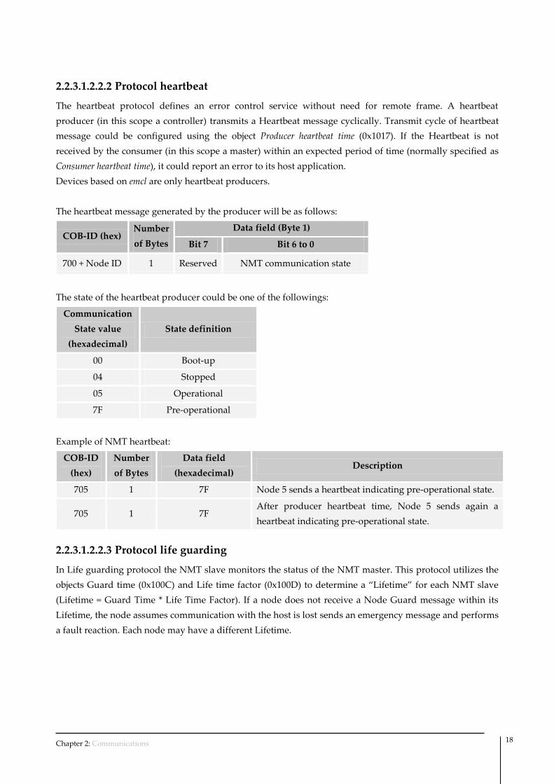
2.2.3.1.2.2.2 Protocol heartbeat
The heartbeat protocol defines an error control service without need for remote frame. A heartbeat
producer (in this scope a controller) transmits a Heartbeat message cyclically. Transmit cycle of heartbeat
message could be configured using the object Producer heartbeat time (0x1017). If the Heartbeat is not
received by the consumer (in this scope a master) within an expected period of time (normally specified as
Consumer heartbeat time), it could report an error to its host application.
Devices based on emcl are only heartbeat producers.
The heartbeat message generated by the producer will be as follows:
COB-ID (hex) Number
of Bytes
Data field (Byte 1)
Bit 7 Bit 6 to 0
700 + Node ID 1 Reserved NMT communication state
The state of the heartbeat producer could be one of the followings:
Communication
State value
(hexadecimal)
State definition
00 Boot-up
04 Stopped
05 Operational
7F Pre-operational
Example of NMT heartbeat:
COB-ID
(hex)
Number
of Bytes
Data field
(hexadecimal) Description
705 1 7F Node 5 sends a heartbeat indicating pre-operational state.
705 1 7F After producer heartbeat time, Node 5 sends again a
heartbeat indicating pre-operational state.
2.2.3.1.2.2.3 Protocol life guarding
In Life guarding protocol the NMT slave monitors the status of the NMT master. This protocol utilizes the
objects Guard time (0x100C) and Life time factor (0x100D) to determine a “Lifetime” for each NMT slave
(Lifetime = Guard Time * Life Time Factor). If a node does not receive a Node Guard message within its
Lifetime, the node assumes communication with the host is lost sends an emergency message and performs
a fault reaction. Each node may have a different Lifetime.
Chapter 2: Communications 19
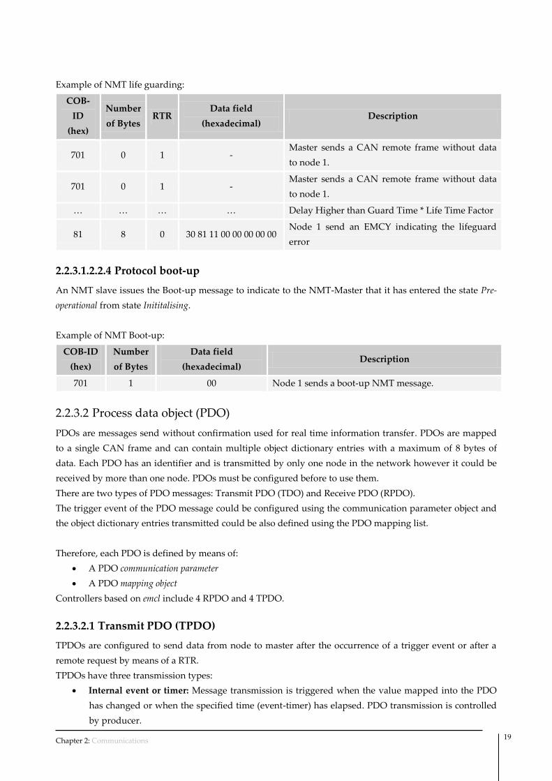
Example of NMT life guarding:
COB-
ID
(hex)
Number
of Bytes RTR
Data field
(hexadecimal) Description
701 0 1 - Master sends a CAN remote frame without data
to node 1.
701 0 1 - Master sends a CAN remote frame without data
to node 1.
… … … … Delay Higher than Guard Time * Life Time Factor
81 8 0 30 81 11 00 00 00 00 00 Node 1 send an EMCY indicating the lifeguard
error
2.2.3.1.2.2.4 Protocol boot-up
An NMT slave issues the Boot-up message to indicate to the NMT-Master that it has entered the state Pre-
operational from state Inititalising.
Example of NMT Boot-up:
COB-ID
(hex)
Number
of Bytes
Data field
(hexadecimal) Description
701 1 00 Node 1 sends a boot-up NMT message.
2.2.3.2 Process data object (PDO)
PDOs are messages send without confirmation used for real time information transfer. PDOs are mapped
to a single CAN frame and can contain multiple object dictionary entries with a maximum of 8 bytes of
data. Each PDO has an identifier and is transmitted by only one node in the network however it could be
received by more than one node. PDOs must be configured before to use them.
There are two types of PDO messages: Transmit PDO (TDO) and Receive PDO (RPDO).
The trigger event of the PDO message could be configured using the communication parameter object and
the object dictionary entries transmitted could be also defined using the PDO mapping list.
Therefore, each PDO is defined by means of:
A PDO communication parameter
A PDO mapping object
Controllers based on emcl include 4 RPDO and 4 TPDO.
2.2.3.2.1 Transmit PDO (TPDO)
TPDOs are configured to send data from node to master after the occurrence of a trigger event or after a
remote request by means of a RTR.
TPDOs have three transmission types:
Internal event or timer: Message transmission is triggered when the value mapped into the PDO
has changed or when the specified time (event-timer) has elapsed. PDO transmission is controlled
by producer.

Chapter 2: Communications 20
Remotely request: Message transmission is initiated on receipt of a RTR message. PDO
transmission is driven by the PDO consumer.
Synchronously trigger: Message transmission is triggered by the reception of a certain number of
SYNC objects (see TPDO1 definition for further information). The PDO transmission is controlled
by the SYNC producer.
Example of an internal event TPDO:
COB-ID
(hex)
Number
of Bytes
Data field
(hexadecimal) Description
182 2 63 22 Node ID 2 sends the Transmit PDO1 with a content value of
0x2263.
2.2.3.2.2 Receive PDO (RPDO)
The master uses the RPDO to write data to objects in the nodes.
RPDOs have two transmission types:
Asynchronous: Message content is applied upon receipt of the RPDO. The PDO reception is
controlled by the PDO producer.
Synchronously trigger: Message content is applied after the reception of a certain number of SYNC
objects. The PDO reception is controlled by the SYNC producer.
Example of an asynchronous RPDO:
COB-ID
(hex)
Number
of Bytes
Data field
(hexadecimal) Description
202 2 22 12 Master sends a RPDO1 to Node 2 with a content value of
0x1222.
2.2.3.2.3 Mapping procedure
The steps to configure the PDO mapping are:
1. Place the controller into NMT pre-operational.
2. Destroy the PDO writing a 1 into the valid bit of SubIndex 0x01 of PDO communication parameter.
3. Set the number of entries of the PDO mapping register to zero.
4. Modify mapping by changing the values in the corresponding SubIndexes.
5. Enable mapping by setting SubIndex 0x00 to the number of mapped objects.
6. Create PDO by setting a 1 into the valid bit of SubIndex 0x01 of PDO communication parameter.
7. Place the controller into NMT operational.
2.2.3.3 Service data object (SDO)
The SDO are communication channels with two basic characteristics:
Client / Server relationship
It provides access to the dictionary of CANopen objects of the device.

Chapter 2: Communications 21
The SDO are used to transfer multiple object content simultaneously objects (each with an arbitrary
amount of information) from client to server and vice versa.
SDO are transferred as a sequence of segments. Before to send the segments there is an initialization
process in which the server and clients prepare themselves to send the segments. However, it is also
possible to send information (up to 4bytes) during the initialization process. This mechanism is called SDO
expedited transfer.
There are two mechanisms for SDO transfer:
Expedited transfer: Used for data objects up to 4 bytes in length.
Segmented transfer: For objects with length larger than 4 bytes.
The first byte of the first segment contains the necessary flow control information including a toggle bit to
overcome the well-known problem of doubly received CAN frames. The next three byte of the first
segment contains index and sub-index of the Object Dictionary entry to be read or written. The last four
bytes of the first segment are available for user data. The second and the following segments (using the
very same CAN identifier) contain the control byte and up to seven byte of user data. The receiver confirms
each segment or a block of segments, so that a peer-to-peer communication
2.2.3.4 Synchronization object (SYNC)
SYNC object is a broadcast message sent by one of the devices in the bus (normally the master) to provide
synchronization to the network and to allow coordination between nodes. The nodes could be
programmed to return any variable (actual position, etc) by means of TPDO at reception of SYNC object.
The SYNC object has no data.
Controllers based on emcl are able also to generate SYNC messages. The cycle period of transmission is
specified using Communication cycle period (object 0x1006)
Example of SYNC:
COB-ID
(hex)
Number
of Bytes
Data field
(hexadecimal) Description
80 0 - Producer sends a SYNC message to all bus nodes.
2.2.3.5 Emergency object (EMCY)
Emergency objects are triggered by the occurrence of a CANopen device internal error situation and are
transmitted from an emergency producer (normally a node) on the CANopen device. An emergency object
is sent only once per error event. Zero or more emergency consumers may receive the emergency object.
The data content of the emergency message uses the following structure:
Byte number: 1 2 3 4 5 6 7 8
Emergency error codes
(Object 0x603F)
Error registers
(Object 0x1001) Reserved (zero values)
Table 6: Emergency data field

Chapter 2: Communications 22
Example of EMCY:
COB-ID
(hex)
Number
of Bytes
Data field
(hexadecimal) Description
89 8 06 73 80 00 00 00 00 00 Node 9 sends a differential encoder broken wire error
(0x7306) emergency message.
2.2.3.5.1 Emergency error codes
A list of hexadecimal Emergency error codes is shown in the following table.
Error code Description
0x0000 No error
0x2200 Hardware peak over-current detected (system protection).
0x2201 Hardware I2T over-current detected (system protection).
0x6320 Parameter error.
0x7305 Error in incremental encoder feedback detected.
0x7306 Differential encoder broken wire detected.
0x8110 CAN bus overrun.
0x8120 CAN in error passive mode.
0x8130 Lifeguard or heartbeat error.
0x8140 Recovered from bus off.
0x8141 Bus off occurred.
0x8150 Transmit COBID collision.
0x8210 PDO not processed due to length error.
0x8220 PDO length exceeded.
0x8613 Timeout during homing process.
0xFF04 Phasing process out of tolerance detected.
0xFF10 Divide by zero instruction detected.
0xFF20 Uart reception overflow
0xFF30 An out of valid range Macro or command address has been executed.
0xFF31 Macro stack is full.
0xFF33 Detected interrupt without associated macro function.
0xFF34 Saving or restoring out of learned position space.
Table 7: Emergency error codes

Chapter 2: Communications 23
2.3 RS232
2.3.1 What is RS232?
RS-232 (also known as Electronic Industries Alliance RS-232C) is an interface that assigns a rule for the
serial interchange of binary data between a DTE (Data Terminal Equipment) and a DCE (Data
Communication Equipment), even though other situations exist in which interface RS-232 is also used.
This interface is designed for short distances, about 15m or less, and for low communication speeds of no
more than 20 KB. In spite of this, it is very often used at higher speeds with acceptable results. The interface
can work in asynchronous or synchronous communication and simplex, half duplex o full duplex channel
types.
2.3.2 Configuration
The RS232 default configuration used in emcl based motion controllers (which must as a result also use the
host) is shown below:
Baudrate 115200 bps
Data bits 8 bits
Parity None
Stop bits 1 bit
Flux control None
The communication baudrate is not fixed and could be modified using the appropriate object.
2.3.3 Command format
Commands used in RS232 communications by emcl based controllers use ASCII codes.
Their format, similar to CANopen communications, contains the following information:
Destination node identifier: It may be a value from 0-127 (both inclusive). It may be expressed in
decimal or hexadecimal format (adding the prefix ‘0x’).
The type of function to be carried out (FCT Field): This may be a read or write operation. When
the FCT field contains a ‘W’ character, it will indicate that the command contains a write process.
If, on the other hand, the FCT character contains an ‘R,’ it will indicate that the process is a read
process.
Object number: The object to work with. The object number is build with the binary combination
of the SubIndex and the Index value. The SubIndex precedes the Index. It may be expressed in
decimal or hexadecimal form (adding the prefix ‘0x’)
Chapter 2: Communications 24
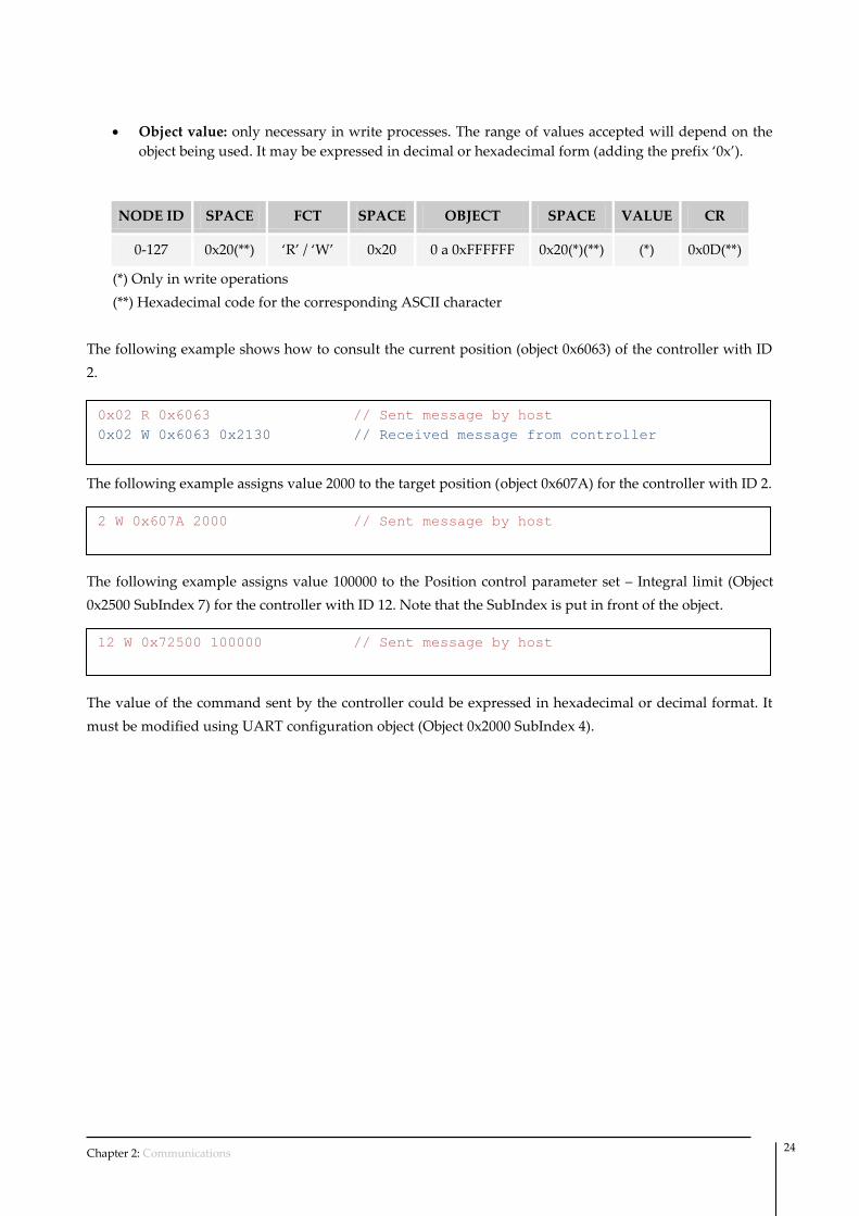
Object value: only necessary in write processes. The range of values accepted will depend on the
object being used. It may be expressed in decimal or hexadecimal form (adding the prefix ‘0x’).
NODE ID SPACE FCT SPACE OBJECT SPACE VALUE CR
0-127 0x20(**) ‘R’ / ‘W’ 0x20 0 a 0xFFFFFF 0x20(*)(**) (*) 0x0D(**)
(*) Only in write operations
(**) Hexadecimal code for the corresponding ASCII character
The following example shows how to consult the current position (object 0x6063) of the controller with ID
2.
The following example assigns value 2000 to the target position (object 0x607A) for the controller with ID 2.
The following example assigns value 100000 to the Position control parameter set – Integral limit (Object
0x2500 SubIndex 7) for the controller with ID 12. Note that the SubIndex is put in front of the object.
The value of the command sent by the controller could be expressed in hexadecimal or decimal format. It
must be modified using UART configuration object (Object 0x2000 SubIndex 4).
0x02 R 0x6063 // Sent message by host
0x02 W 0x6063 0x2130 // Received message from controller
2 W 0x607A 2000 // Sent message by host
12 W 0x72500 100000 // Sent message by host

Chapter 3: Communication profile area 25
This chapter describes the objects defined by the standard CiA-301
3.1 General information
It is strongly recommended to verify and complete the information shown in this section with the eds file
provided by Ingenia together with emcl. For further information about eds format see: CiA Draft Standard
306 – Electronic data sheet specification for CANopen.
3.2 Object dictionary
Device type
Index Sub
Index Name
Data
Type Acc.
Pdo
Map. NVM
Value
range Default value Units
0x1000 0x00 Device type UINT32 RO No No - 0x00020192 -
This object provides information about the device type. The object describes the type of the logical device
and its functionality.
Data description:
It is composed of a 16-bit field that describes the device profile or the application profile that is used and a
second 16-bit field, which gives additional information about optional functionality of the logical device.
Bit number: 31 … 24 23 … 16 15 … 0
Additional information Device profile number
Mode bits Type
In emcl controllers the value should be the followings:
Device profile number: 402 decimal (0x0192)
Additional information: 02 Servo Drive
Error registers
Index Sub
Index Name
Data
Type Acc.
Pdo
Map. NVM
Value
range Default value Units
0x1001 0x00 Error register UINT8 RO No No - - -
This object provides error information. The emcl maps internal errors into this object. It is a part of an
emergency object.
3 Communication profile area

Chapter 3: Communication profile area 26
Data description:
Bit Meaning
0 Generic error
1 Current
2 Voltage
3 Temperature
4 Communication error (overrun, error state)
5 Device profile specific
6 Reserved (always 0)
7 Manufacturer-specific
Pre-defined error field
Index Sub
Index Name
Data
Type Acc.
Pdo
Map. NVM
Value
range Default value Units
0x1003 0x01 Standard error field UINT32 RO No No UINT32 0x00000000 -
0x1003 0x02 Standard error field UINT32 RO No No UINT32 0x00000000 -
0x1003 0x03 Standard error field UINT32 RO No No UINT32 0x00000000 -
0x1003 0x04 Standard error field UINT32 RO No No UINT32 0x00000000 -
This object provides the errors that occurred on the emcl and were signaled via the emergency object. In
doing so it provides an error history.
The object entry at SubIndex 0x00 contains the number of actual errors that are recorded in the array
starting at SubIndex 0x01.
Every new error will be stored at SubIndex 0x01 and older errors will be moved to the next higher sub-
index.
For further information about error codes see Emergency error codes on 22.
COB-ID SYNC
Index Sub
Index Name
Data
Type Acc.
Pdo
Map. NVM
Value
range Default value Units
0x1005 0x00 COB-ID SYNC UINT32 RW No No - 0x00000080 -
This object indicates the configured COB-ID of the synchronization object (SYNC). Further, it defines
whether the emcl generates the SYNC.
emcl only supports 11-bit CAN-ID frame.

Chapter 3: Communication profile area 27
This object only works in emcl CANopen version.
Data description:
Bit number: 31 30 29 28 … 11 10 … 0
x gen. frame
0x00000 11-bit CAN-ID
29-bit CAN-ID
Bit Value Meaning
x x Do not care
Generate 0 CANopen device does not generate SYNC message
1 CANopen device generates SYNC message
Frame 0 11-bit CAN-ID valid (CAN base frame)
1 29-bit CAN-ID valid (CAN extended frame) – not supported
29-bit CAN-ID x 29-bit CAN-ID of the CAN extended frame – not supported
11-bit CAN-ID x 11-bit CAN-ID of the CAN base frame
Communication cycle period
Index Sub
Index Name
Data
Type Acc.
Pdo
Map. NVM
Value
range Default value Units
0x1006 0x00 Communication cycle period UINT32 RW No No UINT32 0x00000000 μs
This object provides the communication cycle period. This period defines the SYNC interval.
If the value is set to 0x00000000 the transmission of SYNC messages is disabled.
This object only works in emcl CANopen version.
Sync window length
Index Sub
Index Name
Data
Type Acc.
Pdo
Map. NVM
Value
range Default value Units
0x1007 0x00 Sync window length UINT32 RW No No UINT32 0x00000000 μs
This object indicates the configured length of the time window for synchronous PDOs.
If the synchronous window length expired all synchronous TPDOs will be discarded and an EMCY
message will be transmitted; all synchronous RPDOs will be discarded until the next SYNC message is
received. Synchronous RPDO processing is resumed with the next SYNC message.
If the value is set to 0x00000000 the synchronous window is disabled.
Chapter 3: Communication profile area 28
This object only works in emcl CANopen version.
Manufacturer device name
Index Sub
Index Name
Data
Type Acc.
Pdo
Map. NVM
Value
range Default value Units
0x1008 0x00 Device name STR CONST No No STR emcl -
This object provides the name of the device as given by the manufacturer.
Manufacturer hardware version
Index Sub
Index Name
Data
Type Acc.
Pdo
Map. NVM
Value
range Default value Units
0x1009 0x00 Hardware version STR CONST No No STR See PCB -
This object provides the manufacturer hardware version description.
Software version
Index Sub
Index Name
Data
Type Acc.
Pdo
Map. NVM
Value
range Default value Units
0x100A 0x00 Software version STR CONST No No STR 0.92 -
This object provides the manufacturer software version description.
Guard time
Index Sub
Index Name
Data
Type Acc.
Pdo
Map. NVM
Value
range Default value Units
0x100C 0x00 Guard time UINT16 RW No No UINT16 0x0000 milliseconds
The objects at Index 0x100C and 0x100D indicate the configured guard time respectively the life time factor.
The life time factor multiplied with the guard time gives the life time for the life guarding protocol.
This object only works in emcl CANopen version.
Life time factor
Index Sub
Index Name
Data
Type Acc.
Pdo
Map. NVM
Value
range Default value Units
0x100D 0x00 Life time factor UINT8 RW No No UINT8 0x00 -
The life time factor multiplied with the guard time gives the life time for the life guarding protocol.

Chapter 3: Communication profile area 29
This object only works in emcl CANopen version.
Store parameters
Index Sub
Index Name
Data
Type Acc.
Pdo
Map. NVM
Value
range Default value Units
0x1010 0x01 Save all parameters UINT32 RW No No UINT32 - -
0x1010 0x02 Save communication parameters UINT32 RW No No UINT32 - -
0x1010 0x03 Save application parameters UINT32 RW No No UINT32 - -
This object controls the saving of parameters into the non-volatile memory.
In order to avoid storage of parameters by mistake, storage is only executed when a specific signature is
written to the appropriate SubIndex. The signature that must be written is "save":
MSB LSB
e v a s
0x65 0x76 0x61 0x73
Restore default parameters
Index Sub
Index Name
Data
Type Acc.
Pdo
Map. NVM
Value
range Default value Units
0x1011 0x01 Restore all parameters UINT32 RW No No UINT32 - -
0x1011 0x02 Restore communication parameters UINT32 RW No No UINT32 - -
0x1011 0x03 Restore application parameters UINT32 RW No No UINT32 - -
With this object the default values of parameters according to the communication profile, device profile,
and application profile are restored.
In order to avoid the restoring of default parameters by mistake, restoring is only executed when a specific
signature is written to the appropriate SubIndex. The signature that must be written is "load":
MSB LSB
d a o l
0x64 0x61 0x6F 0x6C
COB-ID emergency message
Index Sub
Index Name
Data
Type Acc.
Pdo
Map. NVM
Value
range Default value Units
0x1014 0x00 COB-ID emergency message UINT32 RW No No UINT32 0x00000080 + Node ID -
This object indicates the configured COB-ID for the emergency (EMCY) write service.
This object only works in emcl CANopen version.

Chapter 3: Communication profile area 30
Data description:
Bit number: 31 30 29 28 … 11 10 … 0
valid
Reserved
always 0 frame
0x00000 11-bit CAN-ID
29-bit CAN-ID
Bit Value Description
valid 0 EMCY exists / is valid
1 EMCY does not exist / is not valid
frame 0 11-bit CAN-ID valid (CAN base frame)
1 29-bit CAN-ID valid (CAN extended frame) – not supported
29-bit CAN-ID x 29-bit CAN-ID of the CAN extended frame – not supported
11-bit CAN-ID x 11-bit CAN-ID of the CAN base frame
Producer heartbeat time
Index Sub
Index Name
Data
Type Acc.
Pdo
Map. NVM
Value
range Default value Units
0x1017 0x00 Producer heartbeat time UINT16 RW No No UINT16 0x0000 milliseconds
The producer heartbeat time indicates the configured cycle time of the heartbeat. A value of 0 disables the
heartbeat.
This object only works in emcl CANopen version.
Identity Object
Index Sub
Index Name
Data
Type Acc.
Pdo
Map. NVM
Value
range Default value Units
0x1018 0x01 Vendor ID UINT32 RO No No UINT32 0x0000029C -
0x1018 0x02 Product code UINT32 RO No No UINT32 0x00000116 -
0x1018 0x03 Revision number UINT32 RO No No UINT32 0x00000000 -
0x1018 0x04 Serial number UINT32 RO No No UINT32 - -
This object provides general identification information of the CANopen device.
Serial number is a unique identifier for each controller.
SDO Server parameter
Index Sub
Index Name
Data
Type Acc.
Pdo
Map. NVM
Value
range Default value Units
0x1200 0x01 COB-ID Client Server UINT32 RO No No UINT32 0x00000600 + Node ID -

Chapter 3: Communication profile area 31
0x1200 0x02 COB-ID Server Client UINT32 RO No No UINT32 0x00000580 + Node ID -
In order to describe the SDOs used on a CANopen device the data type SDO Parameter is introduced
This object only works in emcl CANopen version.
RPDO1
Index Sub
Index Name
Data
Type Acc.
Pdo
Map. NVM
Value
range Default value Units
0x1400 0x01 COB-ID used UINT32 RW No Yes UINT32 0x80000200 + Node ID -
0x1400 0x02 Transmission type UINT8 RW No Yes UINT8 0xFF -
0x1400 0x03 Inhibit time UINT16 RW No Yes UINT16 0x0000 100μs
This object contains the communication parameters for the PDO 1 the CANopen device is able to receive.
SubIndex description:
0x01 (COB-ID used): The format of COB-ID is as follows:
Bit number: 31 30 29 28 … 11 10 … 0
valid
Reserved
always 0 frame
0x00000 11-bit CAN-ID
29-bit CAN-ID
Bit Value Description
valid 0 PDO exists / is valid
1 PDO does not exist / is not valid
frame 0 11-bit CAN-ID valid (CAN base frame)
1 29-bit CAN-ID valid (CAN extended frame)
29-bit CAN-ID x 29-bit CAN-ID of the CAN extended frame
11-bit CAN-ID x 11-bit CAN-ID of the CAN base frame
0x02 (Transmission type): Indicates the transmission types of the RPDO. From 0x00 to 0xF0
indicates a synchronous reception (data will be update after the reception of the next SYNC), and
0xFE or 0xFF indicated asynchronous reception (the controller will update the value after PDO
reception). The rest of values are reserved.
0x03 (Inhibit time): Not used actually. Reserved for future updates.
This object only works in emcl CANopen version.

Chapter 3: Communication profile area 32
RPDO2
Index Sub
Index Name
Data
Type Acc.
Pdo
Map. NVM
Value
range Default value Units
0x1401 0x01 COB-ID used UINT32 RW No Yes UINT32 0x80000300 + Node ID -
0x1401 0x02 Transmission type UINT8 RW No Yes UINT8 0xFF -
0x1401 0x03 Inhibit time UINT16 RW No Yes UINT16 0x0000 100μs
This object contains the communication parameters for the PDO 2 the CANopen device is able to receive.
For description of SubIndex see RPDO1.
This object only works in emcl CANopen version.
RPDO3
Index Sub
Index Name
Data
Type Acc.
Pdo
Map. NVM
Value
range Default value Units
0x1402 0x01 COB-ID used UINT32 RW No Yes UINT32 0x80000400 + Node ID -
0x1402 0x02 Transmission type UINT8 RW No Yes UINT8 0xFF -
0x1402 0x03 Inhibit time UINT16 RW No Yes UINT16 0x0000 100μs
This object contains the communication parameters for the PDO 3 the CANopen device is able to receive.
For description of SubIndex see RPDO1.
This object only works in emcl CANopen version.
RPDO4
Index Sub
Index Name
Data
Type Acc.
Pdo
Map. NVM
Value
range Default value Units
0x1403 0x01 COB-ID used UINT32 RW No Yes UINT32 0x80000500 + Node ID -
0x1403 0x02 Transmission type UINT8 RW No Yes UINT8 0xFF -
0x1403 0x03 Inhibit time UINT16 RW No Yes UINT16 0x0000 100μs
This object contains the communication parameters for the PDO 4 the CANopen device is able to receive.
For description of SubIndex see RPDO1.
This object only works in emcl CANopen version.
Chapter 3: Communication profile area 33
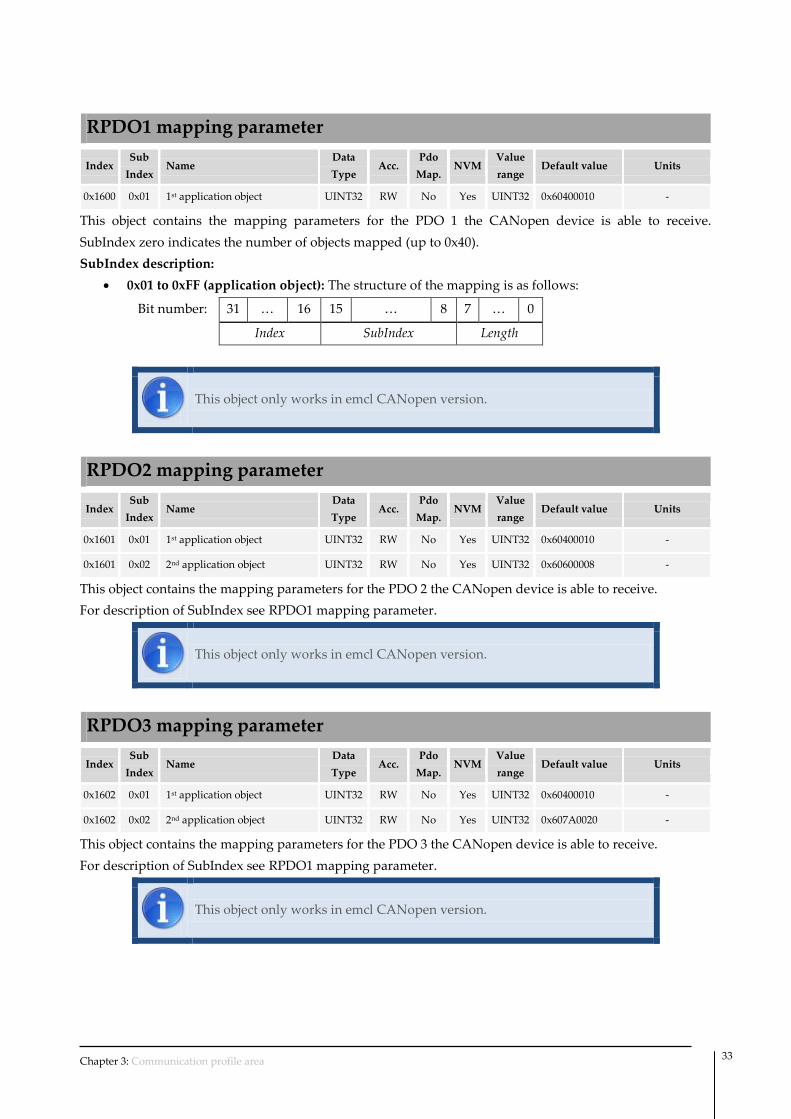
RPDO1 mapping parameter
Index Sub
Index Name
Data
Type Acc.
Pdo
Map. NVM
Value
range Default value Units
0x1600 0x01 1st application object UINT32 RW No Yes UINT32 0x60400010 -
This object contains the mapping parameters for the PDO 1 the CANopen device is able to receive.
SubIndex zero indicates the number of objects mapped (up to 0x40).
SubIndex description:
0x01 to 0xFF (application object): The structure of the mapping is as follows:
Bit number: 31 … 16 15 … 8 7 … 0
Index SubIndex Length
This object only works in emcl CANopen version.
RPDO2 mapping parameter
Index Sub
Index Name
Data
Type Acc.
Pdo
Map. NVM
Value
range Default value Units
0x1601 0x01 1st application object UINT32 RW No Yes UINT32 0x60400010 -
0x1601 0x02 2nd application object UINT32 RW No Yes UINT32 0x60600008 -
This object contains the mapping parameters for the PDO 2 the CANopen device is able to receive.
For description of SubIndex see RPDO1 mapping parameter.
This object only works in emcl CANopen version.
RPDO3 mapping parameter
Index Sub
Index Name
Data
Type Acc.
Pdo
Map. NVM
Value
range Default value Units
0x1602 0x01 1st application object UINT32 RW No Yes UINT32 0x60400010 -
0x1602 0x02 2nd application object UINT32 RW No Yes UINT32 0x607A0020 -
This object contains the mapping parameters for the PDO 3 the CANopen device is able to receive.
For description of SubIndex see RPDO1 mapping parameter.
This object only works in emcl CANopen version.

Chapter 3: Communication profile area 34
RPDO4 mapping parameter
Index Sub
Index Name
Data
Type Acc.
Pdo
Map. NVM
Value
range Default value Units
0x1603 0x01 1st application object UINT32 RW No Yes UINT32 0x60400010 -
0x1603 0x02 2nd application object UINT32 RW No Yes UINT32 0x60FF0020 -
This object contains the mapping parameters for the PDO 4 the CANopen device is able to receive.
For description of SubIndex see RPDO1 mapping parameter.
This object only works in emcl CANopen version.
TPDO1
Index Sub
Index Name
Data
Type Acc.
Pdo
Map. NVM
Value
range Default value Units
0x1800 0x01 COB-ID used UINT32 RW No Yes UINT32 0x40000180 + Node ID -
0x1800 0x02 Transmission type UINT8 RW No Yes UINT8 0xFF -
0x1800 0x03 Inhibit time UINT16 RW No Yes UINT16 1000 100μs
0x1800 0x05 Event time UINT16 RW No Yes UINT16 0x0000 milliseconds
This object contains the communication parameters for the PDO 1 the CANopen device is able to transmit.
SubIndex description:
0x01 (COB-ID used): The format of COB-ID is as follows:
Bit number: 31 30 29 28 … 11 10 … 0
valid RTR frame
0x00000 11-bit CAN-ID
29-bit CAN-ID
Bit Value Description
valid 0 PDO exists / is valid
1 PDO does not exist / is not valid
RTR 0 RTR allowed on this PDO
1 No RTR allowed on this PDO
frame 0 11-bit CAN-ID valid (CAN base frame)
1 29-bit CAN-ID valid (CAN extended frame) – not supported
29-bit CAN-ID x 29-bit CAN-ID of the CAN extended frame – not supported
11-bit CAN-ID x 11-bit CAN-ID of the CAN base frame

Chapter 3: Communication profile area 35
0x02 (Transmission type): Indicates the transmission types of the RPDO.
Value Description
0x00 Synchronous (acyclic) – data will be send only once after of the next SYNC
0x01 Synchronous (cyclic every SYNC) - data will be send cyclically after receive
1 SYNC
0x02 Synchronous (cyclic every 2nd SYNC) - data will be send cyclically after
receive 2 SYNC
…
0xF0 Synchronous (cyclic every 240th SYNC) (cyclic every 2nd SYNC) - data will be
send cyclically after receive 240 SYNC
0xFC-0xFD RTR-only – The PDO is send after the reception of a RTR.
0xFE-0xFF Event-driven – The PDO is send after a timeout of the event timer or
when one of the mapped objects changes.
0x03 (Inhibit time): It is expressed as multiple of 100μs. The value of zero will disable the inhibit
time. The time is the minimum interval for PDO transmission if transmission type is set to 0xFE or
0xFF. This value limits the transmission rate of the TPDOs even if the event time is set to a smaller
time or the mapped objects change faster than the inhibit time.
0x05 (Event time): The time is the maximum interval for PDO transmission if the transmission type
is set to 0xFE or 0xFF. It is expressed as multiple of 1ms. If the event time is reached the PDO will
be automatically transmitted. The value of zero will disable the event-timer.
This object only works in emcl CANopen version.
TPDO2
Index Sub
Index Name
Data
Type Acc.
Pdo
Map. NVM
Value
range Default value Units
0x1801 0x01 COB-ID used UINT32 RW No Yes UINT32 0x40000280 + Node ID -
0x1801 0x02 Transmission type UINT8 RW No Yes UINT8 0xFF -
0x1801 0x03 Inhibit time UINT16 RW No Yes UINT16 1000 100μs
0x1801 0x05 Event time UINT16 RW No Yes UINT16 0x0000 milliseconds
This object contains the communication parameters for the PDO 2 the CANopen device is able to transmit.
For description of SubIndex see TPDO1.
This object only works in emcl CANopen version.

Chapter 3: Communication profile area 36
TPDO3
Index Sub
Index Name
Data
Type Acc.
Pdo
Map. NVM
Value
range Default value Units
0x1802 0x01 COB-ID used UINT32 RW No Yes UINT32 0x40000380 + Node ID -
0x1802 0x02 Transmission type UINT8 RW No Yes UINT8 0xFF -
0x1802 0x03 Inhibit time UINT16 RW No Yes UINT16 1000 100μs
0x1802 0x05 Event time UINT16 RW No Yes UINT16 0x0000 milliseconds
This object contains the communication parameters for the PDO 3 the CANopen device is able to transmit.
For description of SubIndex see TPDO1.
This object only works in emcl CANopen version.
TPDO4
Index Sub
Index Name
Data
Type Acc.
Pdo
Map. NVM
Value
range Default value Units
0x1803 0x01 COB-ID used UINT32 RW No Yes UINT32 0x40000480 + Node ID -
0x1803 0x02 Transmission type UINT8 RW No Yes UINT8 0xFF -
0x1803 0x03 Inhibit time UINT16 RW No Yes UINT16 1000 100μs
0x1803 0x05 Event time UINT16 RW No Yes UINT16 0x0000 milliseconds
This object contains the communication parameters for the PDO 4 the CANopen device is able to transmit.
For description of SubIndex see TPDO1.
This object only works in emcl CANopen version.
TPDO1 mapping parameter
Index Sub
Index Name
Data
Type Acc.
Pdo
Map. NVM
Value
range Default value Units
0x1A00 0x01 1st application object UINT32 RW No Yes UINT32 0x60410010 -
This object contains the mapping for the PDO 1 the device is able to transmit.
SubIndex zero indicates the number of objects mapped (up to 0x40).
SubIndex description:
0x01 to 0xFF (application object): The structure of the mapping is as follows:
Bit number: 31 … 16 15 … 8 7 … 0
Index SubIndex Length

Chapter 3: Communication profile area 37
This object only works in emcl CANopen version.
TPDO2 mapping parameter
Index Sub
Index Name
Data
Type Acc.
Pdo
Map. NVM
Value
range Default value Units
0x1A01 0x01 1st application object UINT32 RW No Yes UINT32 0x60410010 -
0x1A01 0x02 2nd application object UINT32 RW No Yes UINT32 0x60610008 -
This object contains the mapping for the PDO 2 the device is able to transmit.
For description of SubIndex see TPDO1 mapping parameter.
This object only works in emcl CANopen version.
TPDO3 mapping parameter
Index Sub
Index Name
Data
Type Acc.
Pdo
Map. NVM
Value
range Default value Units
0x1A02 0x01 1st application object UINT32 RW No Yes UINT32 0x60410010 -
0x1A02 0x02 2nd application object UINT32 RW No Yes UINT32 0x60640020 -
This object contains the mapping for the PDO 3 the device is able to transmit.
For description of SubIndex see TPDO1 mapping parameter.
This object only works in emcl CANopen version.
TPDO4 mapping parameter
Index Sub
Index Name
Data
Type Acc.
Pdo
Map. NVM
Value
range Default value Units
0x1A03 0x01 1st application object UINT32 RW No Yes UINT32 0x60410010 -
0x1A03 0x02 2nd application object UINT32 RW No Yes UINT32 0x606C0020 -
This object contains the mapping for the PDO 4 the device is able to transmit.
For description of SubIndex see TPDO1 mapping parameter.
This object only works in emcl CANopen version.

Chapter 4: Device profile area 38
This chapter describes the objects defined by the standard CiA-402
4.1 Object classification
The objects are grouped in this chapter by functionalities.
First section details the common objects, or nonfunctional registries. These objects are in charge of
configuring the parameters of controller, the motor and the environment, but they do not allow configuring
specific modes of operation of the controller.
The common objects are sub-classified of the following form:
Drive data
Motor data
Factor group
Device control
Afterward control function or control loop objects are detailed. They are in charge of supervising the main
variables of the system (position, velocity and torque) and to apply more or less excitation to the motor to
guarantee their value. The control loop used at each moment depends on the operation mode in which it
works.
Next, the profiler or trajectories generator objects are described. These objects are in charge of continuously
giving the premise or wished value to the control loop following a trajectory or pre-established profile.
These objects are implicitly used by all modes of operation.
Finally, the denominated section Modes of operation will be described. This section explains all the
possible working method for the emcl. In their subparagraphs the objects of each of the modes of operation
are detailed:
Open loop scalar mode
Homing mode
Profile position mode
Profile velocity mode
Profile torque mode
Cyclic synchronous position mode
4 Device profile area
Chapter 4: Device profile area 39
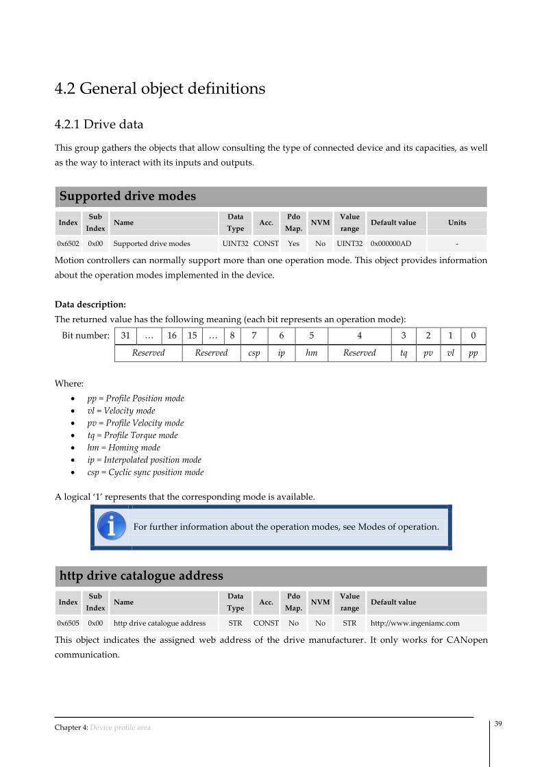
4.2 General object definitions
4.2.1 Drive data
This group gathers the objects that allow consulting the type of connected device and its capacities, as well
as the way to interact with its inputs and outputs.
Supported drive modes
Index Sub
Index Name
Data
Type Acc.
Pdo
Map. NVM
Value
range Default value Units
0x6502 0x00 Supported drive modes UINT32 CONST Yes No UINT32 0x000000AD -
Motion controllers can normally support more than one operation mode. This object provides information
about the operation modes implemented in the device.
Data description:
The returned value has the following meaning (each bit represents an operation mode):
Bit number: 31 … 16 15 … 8 7 6 5 4 3 2 1 0
Reserved Reserved csp ip hm Reserved tq pv vl pp
Where:
pp = Profile Position mode
vl = Velocity mode
pv = Profile Velocity mode
tq = Profile Torque mode
hm = Homing mode
ip = Interpolated position mode
csp = Cyclic sync position mode
A logical ‘1’ represents that the corresponding mode is available.
For further information about the operation modes, see Modes of operation.
http drive catalogue address
Index Sub
Index Name
Data
Type Acc.
Pdo
Map. NVM
Value
range Default value
0x6505 0x00 http drive catalogue address STR CONST No No STR http://www.ingeniamc.com
This object indicates the assigned web address of the drive manufacturer. It only works for CANopen
communication.

Chapter 4: Device profile area 40
4.3 Error codes and error behavior
Error code
Index Sub
Index Name
Data
Type Acc.
Pdo
Map. NVM
Value
range Default value Units
0x603F 0x00 Error code UINT16 RO Yes No UINT16 0x0000 -
The Error code captures the last error detected in the controller.
For further information about error code see Emergency error codes on page
22.
4.3.2 Motor data
Motor type
Index Sub
Index Name
Data
Type Acc.
Pdo
Map. NVM
Value
range Default value Units
0x6402 0x00 Motor type UINT16 RW No Yes UINT16 0x000D -
As Ingenia motion controllers are able to control different typology of motors, it is necessary to specify
which motor is attached to controller. This object indicates the type of motor used.
If this object is modified the phasing is automatically lost and the phasing
process will be repeated once entering into operation enabled status.
Data description:
Value Description
0x000A BLAC (Sinusoidal Back-EMF) - Use sinusoidal currents
0x000B BLDC (Trapezoidal Back-EMF) - Use trapezoidal currents
0x000D Direct Current motor
Motor rated current
Index Sub
Index Name
Data
Type Acc.
Pdo
Map. NVM
Value
range Default value Units
0x6075 0x00 Motor rated current UINT32 RW Yes Yes UINT32 1000 mA
Defines the peak rated current of the motor.
In BLAC or BLDC motors the nominal current in the datasheets is normally expressed as RMS.
To convert RMS current into peak current the value must be multiplied by 2 .
For example if a 2Arms motor is used, the content of this objects must be 2828.

Chapter 4: Device profile area 41
Motor rated torque
Index Sub
Index Name
Data
Type Acc.
Pdo
Map. NVM
Value
range Default value Units
0x6076 0x00 Motor rated torque UINT32 RW Yes Yes UINT32 310 mNm or mN
This object indicates the configured motor rated torque
All definitions refer to rotating motors. Using linear motors requires that all "torque" objects refer to a
"force" instead. For the sake of simplicity, the objects are not duplicated and their names are not modified.
The value is given in mNm (milli Newton metre). For linear motors, the object name is not changed, but the
motor rated force value is entered as multiples of mN (milliNewton).
4.3.3 Factor group
Position encoder resolution
Index Sub
Index Name
Data
Type Acc.
Pdo
Map. NVM
Value
range Default value Units
0x608F 0x01 Encoder increments UINT32 RW Yes Yes UINT32 20000 increment
0x608F 0x02 Motor revolutions UINT32 RW Yes Yes 1 1 revolutions
It specifies the relationship between position feedback increments and mechanical revolutions of the motor.
emcl based controller uses X4 decoding with incremental encoders. So each
transition in any of the two main encoder signals (A, B) will be considered to
be an increment. As an example, if a 500CPR (cycles per revolution) encoder
is used; the value to be configured in this register will be 2000 increments per
mechanical revolution.
When using linear motors, the position encoder resolution refer to pole-pitch
and Motor pair poles object must be set to one.
If this object is modified the phasing is automatically lost and the phasing
process will be repeated once entering into operation enabled status.
Polarity
Index Sub
Index Name
Data
Type Acc.
Pdo
Map. NVM
Value
range Default value Units
0x607E 0x00 Polarity UINT8 RW Yes Yes UINT8 0x00 -
This object indicates if position and velocity demand shall be multiplied by 1 or by -1. Each variable could
be reversed independently using a different bit of polarity register.

Chapter 4: Device profile area 42
The position polarity bit is used by profile position mode and the velocity polarity bit is used by profiled
velocity mode.
This object will not reverse the whole system, it only affects to the position
and velocity demand. Please, see System polarity if you want to reverse the
whole system.
Data description:
The binary representation of the object value and its corresponding meaning is as follows:
Bit number: 7 6 5 4 3 2 1 0
Pos Polarity Vel Polarity Reserved
The bits have the following meanings:
Value Polarity
0 Positive (multiply by 1)
1 Negative (multiply by -1)
A logical “0” shows that the position values will be multiplied by 1. A logical “1” shows that the values
will be multiplied by -1.
4.3.4 Device control
This group of objects is in charge of managing controller functions and is divided into two parts:
Device status machine control
Operation mode selection
Device controlling
Operation mode State Machine
fault
Modes of operation (0x6060)
Statusword (0x6041)
Controller states can be modified through the controlword and consulted through the statusword.

Chapter 4: Device profile area 43
4.3.4.1 State machine
The emcl controller status machine is shown below, as well as a description of each status.
START
NOT READY TO SWITCH ON
(0)
SWITCH ON DISABLED
READY TO SWITCH ON
(2)
FAULT
(1)
FAULT REACTION ACTIVE
(14)
(15)
SWITCH ON
OPERATION ENABLE QUICK STOP ACTIVE
(4) (5)
(6)(3)
(7)
(11)
(8)(9)
(10)
(12)
(13)
The following table indicates which function is applied on every state. Brake is only applied if it is present.
High-level power applied is only selectable in controllers with an embedded contactor/switch for the
power stage.
Function
Not
ready to
switch
on
Switch
on
disable
Ready to
switch on
Switched
on
Operation
enabled
Quick
stop
active
Fault
reaction
active
Fault
Brake applied, if present Yes Yes Yes Yes Yes / No Yes / No Yes / No Yes
Low-level power applied Yes Yes Yes Yes Yes Yes Yes Yes
High-level power applied Yes / No Yes / No Yes / No Yes Yes Yes Yes Yes / No
Drive function enabled No No No No Yes Yes Yes No
Configuration allowed Yes Yes Yes Yes No No No Yes

Chapter 4: Device profile area 44
The controller supports the following events and actions.
Transition Event Action
0 Automatic transition after power-on or reset
application.
Drive device self-test and/or self
initialization is performed.
1 Automatic transition after initialization. Communications are activated.
2 Shutdown command received from control device or
local signal. None.
3 Switch on command received from control device or
local signal. The high-level power is switched on.
4 Enable operation command received from control
device or local signal.
The drive function is enabled, phasing is
executed and all internal set-points
cleared.
5 Disable operation command received from control
device or local signal. The drive function is disabled.
6 Shutdown command received from control device or
local signal. The high-level power is switched off.
7 Quick stop o disable voltage command received from
control device or local signal. None.
8 Shutdown command received from control device or
local signal.
The drive function is disabled, and the
high-level power is switched off.
9 Disable operation command received from control
device or local signal.
The driver function is disabled, and the
high-level power is switched off.
10 Disable voltage o quick stop command received from
control device or local signal. The high-level power is switched off.
11 Quick stop received from control device or local
signal. The quick stop function is started.
12
Automatic transition when the quick stop function
is completed or disable voltage command is received
from control device.
The drive function is disabled, and the
high-level power is switched off.
13 Fault signal. The configured fault reaction function is
executed.
14 Automatic transition. The drive function is disabled, and the
high-level power is switched off.
15 Fault reset command received from control device
or local signal.
A reset of the fault condition is carried
out, if no fault exists currently on the
drive device; after leaving the Fault state,
the Fault reset bit in the controlword is
cleared by the control device.

Chapter 4: Device profile area 45
When drive function is disabled, no energy will be supplied to the motor.
Target or set-point (torque, velocity, position) in that situation are not
processed.
High-level power is switched off only in systems with contactors or switches
for this purpose.
Controlword
Index Sub
Index Name
Data
Type Acc.
Pdo
Map. NVM
Value
range Default value Units
0x6040 0x00 Controlword UINT16 RW Yes No UINT16 0x0000 -
The controlword is used to:
Check controller status.
Check parameters related to operation modes.
Data description:
The binary representation of the object value and its corresponding meaning is as follows:
Bit number 15 … 9 8 7 6 5 4 3 2 1 0
Reserved Halt
Fault
reset Mode specific
Enable
operation
Quick
stop
Enable
voltage
Switch
on
Device control commands are generated by a combination of controlword bits.
Command patterns are shown below:
Command Bit of the controlword
Fault reset Enable operation Quick stop Enable voltage Switch on
Shutdown 0 X 1 1 0
Switch on 0 0 1 1 1
Disable voltage 0 x x 0 x
Quick stop 0 x 0 1 x
Disable operation 0 0 1 1 1
Enable operation 0 1 1 1 1
Fault reset 0 to 1
(rising edge) x x x x
Bits marked with an ‘“x” are irrelevant.
The mode specific bits depend on the mode of operation selected. More information can be found in the
corresponding section:

Chapter 4: Device profile area 46
Controlword in homing mode on page 56.
Controlword in profile position mode on page 66.
Controlword in profile velocity mode on page 68.
Controlword in profile torque mode on page 70.
Controlword in cyclic synchronous position mode on page 72.
Note that Fault reset command will be executed only in a rising edge
transition.
If the halt bit is activated (writing a 1) the movement will be stopped using Quick stop deceleration. After
releasing the halt bit the system will maintain the position or velocity but it will not continue the previous
movement.
When working with BLAC motors with phasing forced, the alignment
process will be executed when executing the Enable operation command for
first time.
Note that the Quick stop bit is activated at a low level.
Statusword
Index Sub
Index Name
Data
Type Acc.
Pdo
Map. NVM
Value
range Default value Units
0x6041 0x00 Statusword UINT16 RO Yes No UINT16 - -
The statusword is used to:
Find out the current controller status.
Find out the operation mode status.
By default, UART version of the emcl controller automatically notifies
through the communication interface about any modification that occurs in
the Statusword, without requiring any prior consultation. See UART
configuration for further information.
Data description:
The following use is given to each statusword bit:
Bit Description
0 Ready to switch on
1 Switched on
2 Operation enabled

Chapter 4: Device profile area 47
Bit Description
3 Fault
4 Voltage enabled
5 Quick stop
6 Switch on disabled
7 Warning
8 Reserved
9 Remote
10 Target reached
11 Reserved
12-13 Operation mode specific
14 Phasing reached
15 Reserved
Bits 0-3, 5 and 6 indicate the device status.
The mode specific bits are defined in the corresponding section:
Statusword in homing mode on page 57.
Statusword in profile position mode on page 66.
Statusword in profile velocity mode on page 68.
Statusword in profile torque mode on page 70.
Statusword in cyclic synchronous position mode on page 72.
Bit 14 indicates if the initial angle determination process necessary for BLAC has been completed correctly.
The connection between status and value in these bits is shown below.
Value (binary) Status
xxxx xxxx x0xx 0000 Not ready to switch on
xxxx xxxx x1xx 0000 Switch on disabled
xxxx xxxx x01x 0001 Ready to switch on
xxxx xxxx x01x 0011 Switched on
xxxx xxxx x01x 0111 Operation enabled
xxxx xxxx x00x 0111 Quick stop active
xxxx xxxx x0xx 1111 Fault reaction active
xxxx xxxx x0xx 1000 Fault
Note that the Quick stop bit is activated at a low level.

Chapter 4: Device profile area 48
Modes of operation
Index Sub
Index Name
Data
Type Acc.
Pdo
Map. NVM
Value
range Default value Units
0x6060 0x00 Mode of operation INT8 RW Yes Yes INT8 1 -
This register modifies the current operation mode.
Data description:
The register value has the following meaning:
Value Modes of operation
-1 Open loop scalar mode
1 Profile position mode
3 Profile velocity mode
4 Profile torque mode
6 Homing mode
8 Cyclic sync position mode
Different values than the specified are reserved and should not be used.
When changing from one mode to another the demand of the controller
variable is not reset. (i.e. when changing from profile velocity mode to profile
torque mode the torque demand is not reset and therefore takes last torque
demand value).
For further information about the modes of operation, see Modes of
operation.
Modes of operation display
Index Sub
Index Name
Data
Type Acc.
Pdo
Map. NVM
Value
range Default value Units
0x6061 0x00 Mode of operation display INT8 RO Yes No INT8 - -
This object provides the actual operation mode.

Chapter 4: Device profile area 49
4.4 Control functions
4.4.1 Position
The position control function is in charge of closing the position loop, or in other words, it ensures that the
controller is all the time in the position demanded by operation modes.
This loop uses the output of the trajectory generator (profiler) and the actual position read using position
feedback as inputs for the algorithm. For further information about the control loop implementation see
Position control parameters set.
Loop behavior will strongly depend on the value of used parameter set, which can be modified by the user
through the corresponding objects.
The output of the loop will be used as input for the flux-torque or current loop.
Position demand value
Index Sub
Index Name
Data
Type Acc.
Pdo
Map. NVM
Value
range Default value Units
0x6062 0x00 Position demand value INT32 RO Yes No INT32 0 increments
Position demand is the output generated by the profiler and it us used as position control input.
Position actual internal value
Index Sub
Index Name
Data
Type Acc.
Pdo
Map. NVM
Value
range Default value Units
0x6063 0x00 Position actual internal value INT32 RO Yes No INT32 - increments
This object contains the actual position calculated using the position feedback.
Position actual value
Index Sub
Index Name
Data
Type Acc.
Pdo
Map. NVM
Value
range Default value Units
0x6064 0x00 Position actual value INT32 RO Yes No INT32 - increments
This object contains the actual position calculated using the position feedback.
Following error actual value
Index Sub
Index Name
Data
Type Acc.
Pdo
Map. NVM
Value
range Default value Units
0x60F4 0x00 Following error actual value INT32 RO Yes No INT32 - increments
This object provides the actual value of the following error, which is the difference between the position
demand and actual position (error = demand – actual).

Chapter 4: Device profile area 50
Control effort
Index Sub
Index Name
Data
Type Acc.
Pdo
Map. NVM
Value
range Default value Units
0x60FA 0x00 Control effort INT32 RO Yes No INT32 - -
This object provides the control effort, which is the output of the position control loop.
Position demand internal value
Index Sub
Index Name
Data
Type Acc.
Pdo
Map. NVM
Value
range Default value Units
0x60FC 0x00 Position demand internal value INT32 RO Yes No INT32 - increments
Position demand is the output generated by the profiler and it us used as position control input.
Following error window
Index Sub
Index Name
Data
Type Acc.
Pdo
Map. NVM
Value
range Default value Units
0x6065 0x00 Following error window UINT32 RW Yes Yes UINT32 0xFFFFFFFF increments
This object indicates the configured range of tolerated position values symmetrically to the position
demand value.
If the position actual value is out of the following error window for a Following error time out time, a
following error occurs. When the error condition is detected, the Following error bit (bit number 13) of the
statusword will be set. A following error may occur when a drive is blocked, when an unreachable profile
velocity occurs, or when using wrong closed-loop coefficients. If the value of the following error window is
set to 0xFFFFFFFF, the following control is automatically switched off.
Following error time out
Index Sub
Index Name
Data
Type Acc.
Pdo
Map. NVM
Value
range Default value Units
0x6066 0x00 Following error timeout UINT16 RW Yes Yes UINT16 100 milliseconds
acceptance following error tolerance
following error
window
position
no following error
reference position
following error
following error
window
following error
Figure 5: Following error window (definitions)

Chapter 4: Device profile area 51
This object indicates the minimum time that actual position must be out of following error window in
order to generate an error. When the error condition is detected, the Following error bit (bit number 13) of
the statusword will be set
Position window
Index Sub
Index Name
Data
Type Acc.
Pdo
Map. NVM
Value
range Default value Units
0x6067 0x00 Position window UINT32 RW Yes Yes UINT32 100 increments
This object indicates the configured symmetrical range of accepted positions relative to the target position.
If the actual value of the position encoder is within the position window for Position window time, the
target position is regarded as having been reached. When that situation is detected, the Target reached bit
(bit number 10) of the statusword will be set.
The target position is handled in the same manner as in the profiler concerning limiting functions and
transformation into internal machine units before it is used with this function. If the value of the position
window is set to 0xFFFFFFFF, the position window control is switched off.
Figure 6: Position window (definitions)
Position window time
Index Sub
Index Name
Data
Type Acc.
Pdo
Map. NVM
Value
range Default value Units
0x6068 0x00 Position window time UINT16 RW Yes Yes UINT16 10 milliseconds
This object indicates the minimum time that actual position must be within the Position window to
consider a target reached situation. When that situation is detected, the Target reached bit (bit number 10) of
the statusword will be set
acceptance position range
position window position window
position
position reached
target position
position not reached position not reached

Chapter 4: Device profile area 52
4.4.2 Velocity
This controller do not use a specific control loop for velocity, instead it uses the position control loop.
Thanks to that it is possible to achieve soft movements even at low speeds.
Velocity actual value
Index Sub
Index Name
Data
Type Acc.
Pdo
Map. NVM
Value
range Default value Units
0x606C 0x00 Velocity actual value INT32 RO Yes No INT32 - increments / s
This object contains the actual velocity calculated using the position feedback.
Velocity demand value
Index Sub
Index Name
Data
Type Acc.
Pdo
Map. NVM
Value
range Default value Units
0x606B 0x00 Velocity demand value INT32 RO Yes No INT32 - increments / s
This object provides the instantaneous demand velocity generated by trajectory generator (profiler). It is an
internal object of the device.
Positive values indicate forward direction and negative values indicate reverse direction.
Velocity window
Index Sub
Index Name
Data
Type Acc.
Pdo
Map. NVM
Value
range Default value Units
0x606D 0x00 Velocity window UINT16 RW Yes Yes UINT16 1000 increments / s
This object indicates the configured symmetrical range of accepted velocities to the target velocity. If the
actual value of the velocity is within the velocity window for Velocity window time, the target velocity is
regarded as having been reached. When that situation is detected, the Target reached bit (bit number 10) of
the statusword will be set.
Figure 7: Velocity window (definitions)
acceptance velocity range
velocity window velocity window
velocity
velocity reached
target velocity
velocity not reached velocity not reached

Chapter 4: Device profile area 53
Velocity window time
Index Sub
Index Name
Data
Type Acc.
Pdo
Map. NVM
Value
range Default value Units
0x606E 0x00 Velocity window time UINT16 RW Yes Yes UINT16 10 milliseconds
This object indicates the minimum time that actual velocity must be within the Velocity window to
consider a target reached situation. When that situation is detected, the Target reached bit (bit number 10) of
the statusword will be set
Velocity threshold
Index Sub
Index Name
Data
Type Acc.
Pdo
Map. NVM
Value
range Default value Units
0x606F 0x00 Velocity threshold UINT16 RW Yes Yes UINT16 1000 increments / s
This object indicates the configured zero velocity threshold.
When the velocity actual is below the velocity threshold longer than Velocity threshold time, the motor is
considered stopped and the speed bit (bit number 12) of the statusword is set.
Velocity threshold time
Index Sub
Index Name
Data
Type Acc.
Pdo
Map. NVM
Value
range Default value Units
0x6070 0x00 Velocity threshold time UINT16 RW Yes Yes UINT16 100 milliseconds
This object indicates the minimum time that actual velocity must be below Velocity threshold to consider
zero velocity. When that situation is detected, the speed bit (bit number 12) of the statusword will be set.
4.4.3 Torque
The torque control function is in charge of closing the torque loop, or in other words, it ensures that the
controller is generating the torque demanded by operation modes at all times.
In BLAC motors this loop works in rotational d-q frame (direct & quadrature), where direct components
represents the desired flux and quadrature represents torque. The system tries to raise flux to zero. For
further information about flux and torque control see Flux control parameters set.
In DC or BLAC motors only the quadrature loop is used.
This loop uses the output of the trajectory generator (profiler) when working in profiled torque mode or
the outputs of the other control loops (position, velocity) and the actual torque read using torque feedback
as input for the algorithm. For further information about the control loop implementation see Torque
control parameters set.
Loop behavior will strongly depend on its parameters, which can be modified by the user through the
corresponding registers.

Chapter 4: Device profile area 54
Torque actual value
Index Sub
Index Name
Data
Type Acc.
Pdo
Map. NVM
Value
range Default value Units
0x6077 0x00 Torque actual value INT16 RO Yes No INT16 - ‰ rated torque
This object provides the actual value of the motor. It corresponds to the instantaneous torque in the motor.
Current actual value
Index Sub
Index Name
Data
Type Acc.
Pdo
Map. NVM
Value
range Default value Units
0x6078 0x00 Current actual value INT16 RO Yes No INT16 - ‰ rated current
This object provides the actual value of the current. It corresponds to the current in the motor.
Chapter 4: Device profile area 55
4.5 Modes of operation
This section defines all operation modes supported by emcl.
The operation modes define the controller behavior.
emcl based controllers can include the following operation modes:
Open loop scalar mode: This mode allows exciting a motor without any sensor in open loop
controlling only the applied voltage.
Homing mode: This mode provides various methods to locate the home position or absolute
reference of the system.
Profile position mode: This mode provides system positioning. Velocity, position and acceleration
can be limited and at the same time profile movements can be made using the profiler.
Profile velocity mode: This mode is used to control system velocity without considering position. It
also provides limiting functions and the use of profiles through the profiler.
Profile torque mode: This mode is used to control the torque generated by the system. It also
provides limiting functions and the use of profiles through the profiler.
Cyclic sync position mode: This mode provides system positioning without using internal profiler.
Position can be limited.

Chapter 4: Device profile area 56
4.5.1 Open loop scalar mode
Open loop scalar mode allows exciting the motor in open loop controlling only the applied voltage. The
commutation frequency if fixed internally.
When using BLAC or BLDC motors, this mode generates a sinusoidal current at the specified frequency,
however it cannot guarantee that maximum torque is produced.
Target duty
Index Sub
Index Name
Data
Type Acc.
Pdo
Map. NVM
Value
range Default value Units
0x2F01 0x00 Target duty INT16 RW Yes No INT16 0x0000 Dc bus / 32767
This registry allows assigning the working cycle used in open loop mode. Target duty equal to zero will
not apply any voltage to the motor. In the same way a target duty equal to 32767 will apply the maximum
voltage in one direction and -32767 will apply the maximum voltage in the opposite direction.
4.5.2 Homing mode
In positioning systems, it is usually necessary to know the absolute position of the mechanics to assure
correct movements. For cost reasons, most of systems do not usually use absolute encoders which provide
an absolute reference, and therefore a homing process or search for an absolute reference method is
mandatory.
This chapter describes the methods and functions used by the controller to search for the home position
(also called absolute reference).
In a typical homing method cycle there are two homing speeds; the faster speed is used to find the switch
or mechanical limit and the slower speed is used to find the index pulse.
By choosing a homing method, the following behavior is determined:
Controlword in homing mode
The homing mode uses some bits of the controlword and the statusword for mode-specific-purposes.
The binary representation of the specific controlword bits and its corresponding meaning is as follows:
Bit number: 15 … 9 8 7 6 5 4 3 … 0
- Halt - Reserved
Homing
operation start -
The action taken is described below, depending on the value of each bit:

Chapter 4: Device profile area 57
Name Value Description
Homing
operation
start
0 Do not start homing procedure
1 Start or continue homing procedure
Halt 0 Execute the instruction of bit 4
1 Stop axis with homing acceleration
Statusword in homing mode
The binary representation of the register value and its corresponding meaning is as follows:
Bit number: 15 14 13 12 11 10 9 … 0
-
Homing
error
Homing
attained -
Target
reached -
The meaning of each bit is described below, depending on its value:
Homing
error
Homing
attained
Target
reached Description
0 0 0 Homing procedure is in progress
0 0 1 Homing procedure is interrupted or not started
0 1 0 Homing is attained but target is not reached
0 1 1 Homing mode carried out successfully
1 0 0
Homing error occurred;
Homing mode carried out not successfully;
Velocity is not zero
1 0 1
Homing error occurred;
Homing mode carried out not successfully;
Velocity is zero
1 1 x Reserved
Homing speeds
Index Sub
Index Name
Data
Type Acc.
Pdo
Map. NVM
Value
range Default value Units
0x6099 0x01 Speed during search for switch
or mechanical limit UINT32 RW No Yes UINT32 50000 increments / s
0x6099 0x02 Speed during search for zero UINT32 RW No Yes UINT32 5000 increments / s
Two search speeds are used during the typical homing process, a fast one to locate the switch position or
mechanical limit and a very slow one to find the encoder index pulse.
Increasing homing speeds can affect the accuracy of switch/index detection,
since the device reaction time is reduced.

Chapter 4: Device profile area 58
Homing acceleration
Index Sub
Index Name
Data
Type Acc.
Pdo
Map. NVM
Value
range Default value Units
0x609A 0x01 Homing acceleration UINT32 RW No Yes UINT32 100000 increments / s2
This parameter establishes the acceleration used for all accelerations and decelerations in standard homing
methods.
Home offset
Index Sub
Index Name
Data
Type Acc.
Pdo
Map. NVM
Value
range Default value Units
0x607C 0x00 Home offset INT32 RW No Yes INT32 0 increments
This object indicates the configured difference between the zero position for the application and the
machine home position (found during homing). During homing, the machine home position is found and
once the homing is completed, the zero position is offset from the home position by adding the home offset
to the home position.
A negative value indicates opposite direction.
Homing method
Index Sub
Index Name
Data
Type Acc.
Pdo
Map. NVM
Value
range Default value Units
0x6098 0x01 Homing method INT8 RW No Yes INT8 -2 -
The controller has various methods of finding Home through limit switches or contacts. Most methods also
use the index pulses of incremental encoders to improve detection accuracy.
An encircled number in the figures following figures indicates the code for selection of this homing
position. The direction of movement is also indicated
In the diagrams of homing sequences shown below, the encoder count increases as the axis's position
moves to the right, in other words, the left is the minimum position and the right is the maximum position.
This object is used to select the homing method.
Data description:
The register value has the following meaning:
Value Homing method
-128..-5 Reserved
-4 Homing on the positive mechanical limit
-3 Homing on the negative mechanical limit
-2 Homing on the positive mechanical limit and index pulse
-1 Homing on the negative mechanical limit and index pulse

Chapter 4: Device profile area 59
Value Homing method
0 No homing operation
1…32 Reserved
33 Homing on negative index pulse
34 Homing on positive index pulse
35 Homing on current position
The following sections show details of possible methods available in the controller.
Methods 33 and 34: Homing on the index pulse
By using methods 33 and 34, the homing direction is negative or positive respectively. The home position
will be the first index pulse found in the selected direction.
The homing process should be done within the time specified by the Homing timeout register; Otherwise
the Homing process is aborted, the statusword error bit is raised and an emergency message is sent.
Method 35: Homing on the current position
In method 35, the current position will be used as home position. This method does not require the
controller to be in operation enabled state.
Although this method does not involve any movement, homing parameters
must still be loaded by activating the New-setpoint bit in the controlword
and subsequently running the process, resetting the same bit.
Method -1: Homing on the negative mechanical limit and index pulse
This method starts the movement in a negative direction (to the left in the figure) until a mechanical limit is
detected. The home position is the first index pulse to the right of this position. The system considers that a
mechanical limit has been reached when the Torque actual value exceed the Torque limit of the Homing
extra parameters register.
The whole homing process should be done within the time specified by the Homing timeout register;
Otherwise the Homing process is aborted, the statusword error bit is raised and an emergency message is
sent.

Chapter 4: Device profile area 60
Method -2: Homing on the positive mechanical limit and index pulse
This method starts the movement in a positive direction (to the right in the figure) until a mechanical limit
is detected. The home position is the first index pulse to the left of this position. The system considers that a
mechanical limit has been reached when the Torque actual value exceed the Torque limit of the Homing
extra parameters register.
The whole homing process should be done within the time specified by the Homing timeout register;
Otherwise the Homing process is aborted, the statusword error bit is raised and an emergency message is
sent.
Method -3: Homing on the negative mechanical limit
This method starts the movement in a negative direction (to the left in the figure) until a mechanical limit is
detected. The system considers that a mechanical limit has been reached when the Torque actual value
exceed the Torque limit of the Homing extra parameters register.
The whole homing process should be done within the time specified by the Homing timeout register;
Otherwise the Homing process is aborted, the statusword error bit is raised and an emergency message is
sent.

Chapter 4: Device profile area 61
Method -4: Homing on the positive mechanical limit
This method starts the movement in a positive direction (to the right n the figure) until a mechanical limit
is detected. The system considers that a mechanical limit has been reached when the Torque actual value
exceed the Torque limit of the Homing extra parameters register.
The whole homing process should be done within the time specified by the Homing timeout register;
Otherwise the Homing process is aborted, the statusword error bit is raised and an emergency message is
sent.
4.5.3 Profiler
Max profile velocity
Index Sub
Index Name
Data
Type Acc.
Pdo
Map. NVM
Value
range Default value Units
0x607F 0x00 Max profile velocity UINT32 RW Yes Yes UINT32 2000000 increments / s
This object indicates the configured maximal allowed velocity in either direction during a profiled motion.
The profiler will use as maximum velocity the most restrictive velocity between max profile velocity and
max motor speed.
Max motor speed
Index Sub
Index Name
Data
Type Acc.
Pdo
Map. NVM
Value
range Default value Units
0x6080 0x00 Max motor speed UINT32 RW Yes Yes UINT32 50000 increments / s

Chapter 4: Device profile area 62
This object indicates the configured maximal allowed speed for the motor in either direction. It is used to
protect the motor and is taken from the motor data sheet.
The profiler will use as maximum velocity the most restrictive velocity between max profile velocity and
max motor speed.
Profile velocity
Index Sub
Index Name
Data
Type Acc.
Pdo
Map. NVM
Value
range Default value Units
0x6081 0x00 Profile velocity UINT32 RW Yes Yes UINT32 2000000 increments / s
This object indicates the configured velocity normally attained at the end of the acceleration ramp during a
profiled motion and it is valid for both directions of motion.
If this velocity is higher than Max motor speed or than Max profile velocity it will be restricted by the
profiler.
Profile acceleration
Index Sub
Index Name
Data
Type Acc.
Pdo
Map. NVM
Value
range Default value Units
0x6083 0x00 Profile acceleration UINT32 RW Yes Yes UINT32 7000000 increments / s2
This object indicates the configured acceleration used by the profiler.
If this acceleration is higher than Max acceleration it will be restricted by the profiler.
Profile deceleration
Index Sub
Index Name
Data
Type Acc.
Pdo
Map. NVM
Value
range Default value Units
0x6084 0x00 Profile deceleration UINT32 RW Yes Yes UINT32 7000000 increments / s2
This object indicates the configured deceleration.
If this deceleration is higher than Max deceleration it will be restricted by the profiler.
Quick stop deceleration
Index Sub
Index Name
Data
Type Acc.
Pdo
Map. NVM
Value
range Default value Units
0x6085 0x00 Quick stop deceleration UINT32 RW Yes Yes UINT32 7000000 increments / s2
This object indicates the configured deceleration used to stop the motor when the quick stop function is
activated. If this acceleration is higher than Max acceleration it will be restricted by the profiler.
Motion profile type
Index Sub
Index Name
Data
Type Acc.
Pdo
Map. NVM
Value
range Default value Units
0x6086 0x00 Motion profile type INT16 RW Yes Yes INT16 0x0000 -
This object indicates the configured type of motion profile used to perform a profiled motion.

Chapter 4: Device profile area 63
Data description:
The register value has the following meaning:
Value Definition
-32768…-1 Reserved
0 Trapezoidal profile
1…32767 Reserved
Max acceleration
Index Sub
Index Name
Data
Type Acc.
Pdo
Map. NVM
Value
range Default value Units
0x60C5 0x00 Max acceleration UINT32 RW Yes Yes UINT32 7000000 increments / s2
This object indicates the configured maximal acceleration. It is used to limit the acceleration to an
acceptable value in order to prevent the motor and the moved mechanics from being destroyed.
Max deceleration
Index Sub
Index Name
Data
Type Acc.
Pdo
Map. NVM
Value
range Default value Units
0x60C6 0x00 Max deceleration UINT32 RW Yes Yes UINT32 7000000 increments / s2
This object indicates the configured maximal deceleration. It is used to limit the deceleration to an
acceptable value in order to prevent the motor and the moved mechanics from being destroyed.
4.5.4 Profile position mode
This chapter describes the methods and functions used by the controller in profile position mode.
Movements made in this mode will follow a profile created by the Trajectory generator or Profiler. The user
may control and limit some parameters such as velocity, acceleration or deceleration used by profiler.
The following diagram shows the internal structure of this mode.
Trajectory generator
Position control function
Position demand
value
Target position
Control effort
Trajectory generator
parameters
Position control
parameters
Figure 8: Profile position operation mode diagram
The target position is delivered to the profiler, which using the parameters preset by the user, continuously
generates the values for the desired position. This position is used by the position control function (see
Position control parameters set).

Chapter 4: Device profile area 64
The setting of set-points is controlled by the timing of the new set-point bit and the change set immediately
bit in the controlword as well as the set-point acknowledge bit in the statusword.
After a Target position is applied to the drive device, the control device signals that the set-point is valid by
a rising edge of the new set-point bit in the controlword. The drive device sets the set-point acknowledge
bit in the statusword to 1, and afterwards, the drive device signals with the set-point acknowledge bit set to
0 its ability to accept new set-points. An example is shown in Figure 9.
velocity
time
New SP
SP ACK
Target R.
Change I.
Figure 9: set-point example
If one set-point is still in progress and a new one is validated, two methods of handling are supported:
single set-point (change set immediately bit of controlword is 1) and set of setpoints (change set
immediately bit of controlword is 0).
Single set-point
When a set-point is in progress and a new set-point is validated by the new set-point (bit 4) in the
controlword, the new set-point shall be processed immediately. The handshaking procedure shown in
Figure 10 is used for the single set-point method.
velocity
time
New SP
SP ACK
Target R.
Change I.
Figure 10: Single set-point with Change set immediately active

Chapter 4: Device profile area 65
Set of set-points
When a set-point is in progress and a new set-point is validated by the new set-point (bit 4) in the
controlword, the new set-point shall be processed only after the previous has been reached. The
handshaking procedure shown in Figure 11 is used for the set of set-points method.
velocity
time
New SP
SP ACK
Target R.
Change I.
Figure 11: Set of set-points
New set-points are buffered in the set-point list as long as free set-points are available in the drive device.
emcl has a buffer with space for 16 set-points. If no set-point is in progress, the new set-point will become
active immediately.
If a set-point is in progress, the new set-point will be stored in the first set-point buffer that is free.
The target reached will remain 0 until all set-points are processed.
If all set-point buffers are busy the set-point acknowledge bit will remain active (value 1) until a buffer is
freed as shown in Figure 12.
velocity
time
New SP
SP ACK
Target R.
Change I.
Figure 12: Buffer of set of set-points full
If the change set immediately bit is set to 1, the new set-point will be processed immediately as single set-
point. All previously loaded set-points will be discarded.

Chapter 4: Device profile area 66
Controlword in profile position mode
The profile position mode uses some bits of the controlword and the statusword for mode specific
purposes. The binary representation of the controlword is as follows:
Bit number: 15 … 9 8 7 6 5 4 3 … 0
- Halt - Abs / rel
Change set
immediately
New set-
point -
If no positioning is in progress, the rising edge of bit 4 will start the positioning of the axis. In case a
positioning is in progress, the definitions given in the following table shall be used.
Change set
immediately
New set-
point Description
0 01 Actual positioning will completed (target reached)
before the next one gets started (Set of set-points mode)
1 01 Next positioning shall be started immediately
interrupting the actual one.
Next table defines the values for bit 6 and 8 of the controlword.
Name Value Description
Abs / rel 0 Target position is an absolute value.
1 Target position is a relative value.
Halt 0 Execute positioning.
1 Stop axis with profile deceleration.
Statusword in profile position mode
The binary representation of the register value and its corresponding meaning is as follows:
Bit number: 15 14 13 12 11 10 9 … 0
-
Following
error
Set-point
acknowledge - Target reached -
The meaning of each bit is described below, depending on its value:
Name Value Description
Target reached
0 Halt = 0: Target position not reached
Halt = 1: Axis decelerates
1 Halt = 0: Target position reached
Halt = 1: Axis has velocity 0
Set-point
acknowledge
0 Trajectory generator has not assumed the positioning
values
1 Trajectory generator has assumed the positioning values

Chapter 4: Device profile area 67
Name Value Description
Following error 0 No following error
1 Following error
Target position
Index Sub
Index Name
Data
Type Acc.
Pdo
Map. NVM
Value
range Default value Units
0x607A 0x00 Target position INT32 RW Yes No INT32 0x00000000 increments
The target position is the position where the motor has to move in profile position mode by using current
movement parameters (velocity, acceleration, deceleration, profile type, etc.).
The target position will be interpreted as absolute or relative; depending on the controlword's abs/rel flag
(see 5HControlword in profile position mode).
Software position limit
Index Sub
Index Name
Data
Type Acc.
Pdo
Map. NVM
Value
range Default value Units
0x607D 0x01 Min position limit INT32 RW Yes Yes INT32 0x80000000 increments
0x607D 0x02 Max position limit INT32 RW Yes Yes INT32 0x7FFFFFFF increments
It contains two parameters, a minimum position limit and a maximum position limit.
These parameters define the absolute position limits for the target and current position. Every new target
position will be checked and adjusted to the limits established by these values.
They are expressed in increments and are always related to the home position of the machine.
4.5.5 Profile velocity mode
This chapter describes the methods and functions used by the controller in the profile velocity mode.
Movements made in this mode will follow a profile. The sensor used to calculate velocity is the same as
that used to calculate position.
The following diagram shows the internal working of this mode.
Trajectory generator
Position control function
Positiondemand
value
Target velocity
Control effort
Trajectory generator
parameters
Position control
parameters
Figure 13: Profile velocity operation mode diagram

Chapter 4: Device profile area 68
The target velocity is delivered to the profiler, which thanks to the parameters preset by the user,
continuously generates the desired position. This position will be used in the position control function (see
Position control parameters set).
The target velocity is processed automatically upon reception, and once the velocity is reached is signaled
by means of the statusword as shown in Figure 14.
velocity
time
Target velocity
Target R.
Figure 14: Profile velocity timing
Controlword in profile velocity mode
The binary representation of the register value and its corresponding meaning is as follows:
Bit number: 15 … 9 8 7 6 5 4 3 … 0
- Halt - Reserved - - -
The action taken is described below, depending on the value of each bit:
Name Value Description
Halt 0 The profile velocity movement must be executed.
1 Axis must be stopped.
Statusword in profile velocity mode
The binary representation of the register value and its corresponding meaning is as follows:
Bit number: 15 14 13 12 11 10 9 … 0
- - Speed - Target reached -
The meaning of each bit is described below, depending on its value:
Name Value Description
Target reached
0 Halt = 0: Target velocity not reached
Halt = 1: Axis decelerates
1 Halt = 0: Target velocity reached
Halt = 1: Axis has velocity 0
Speed
0 Speed is not equal 0
1 Speed is equal 0 (motor speed is considered to be zero when it is below
velocity threshold value)
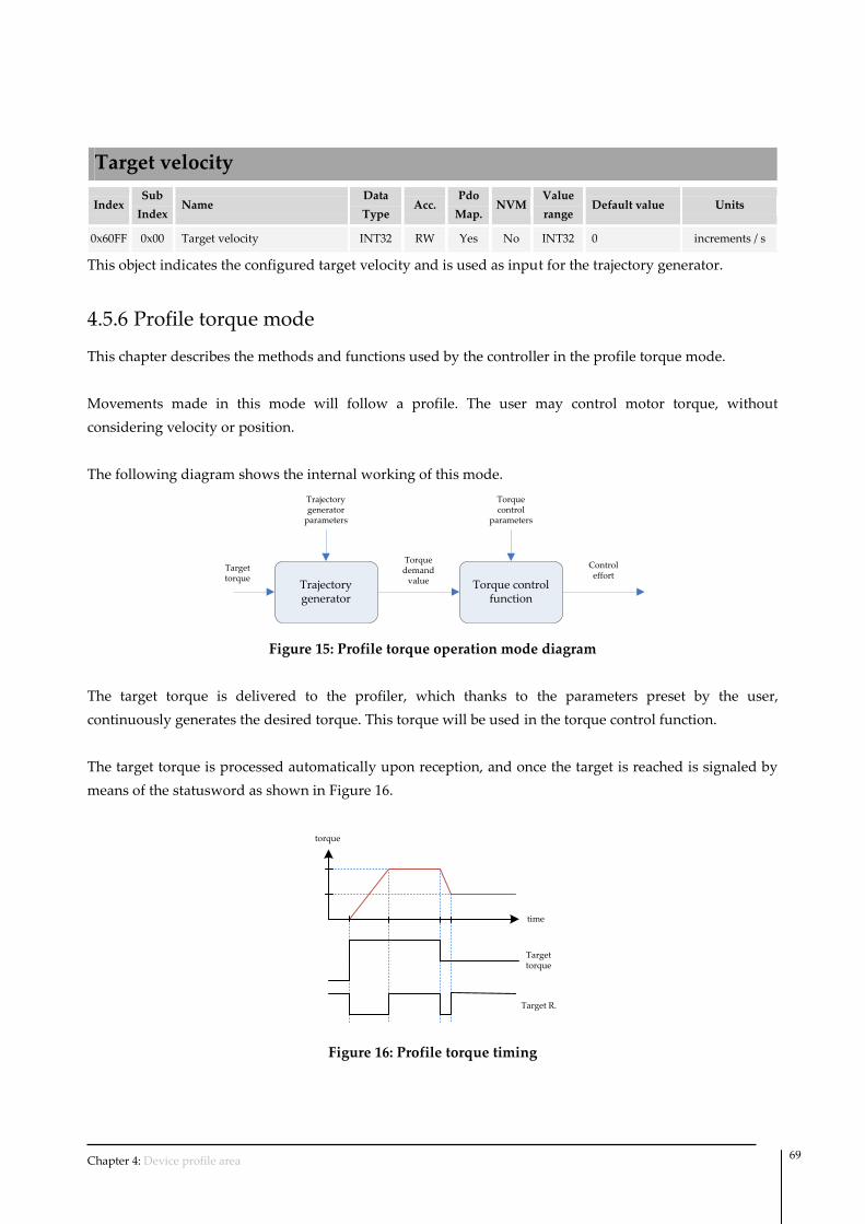
Chapter 4: Device profile area 69
Target velocity
Index Sub
Index Name
Data
Type Acc.
Pdo
Map. NVM
Value
range Default value Units
0x60FF 0x00 Target velocity INT32 RW Yes No INT32 0 increments / s
This object indicates the configured target velocity and is used as input for the trajectory generator.
4.5.6 Profile torque mode
This chapter describes the methods and functions used by the controller in the profile torque mode.
Movements made in this mode will follow a profile. The user may control motor torque, without
considering velocity or position.
The following diagram shows the internal working of this mode.
Trajectory generator
Torque control function
Torque demand
value
Target torque
Control effort
Trajectory generator
parameters
Torque control
parameters
Figure 15: Profile torque operation mode diagram
The target torque is delivered to the profiler, which thanks to the parameters preset by the user,
continuously generates the desired torque. This torque will be used in the torque control function.
The target torque is processed automatically upon reception, and once the target is reached is signaled by
means of the statusword as shown in Figure 16.
torque
time
Target torque
Target R.
Figure 16: Profile torque timing
Chapter 4: Device profile area 70
Controlword in profile torque mode
The binary representation of the register value and its corresponding meaning is as follows:
Bit number: 15 … 9 8 7 6 5 4 3 … 0
- Halt - Reserved - - -
The action taken is described below, depending on the value of each bit:
Name Value Description
Halt 0 The profile torque movement must be executed.
1 Axis must be stoped.
Statusword in profile torque mode
The binary representation of the register value and its corresponding meaning is as follows:
Bit number: 15 14 13 12 11 10 9 … 0
- - - - Target reached -
The meaning of each bit is described below, depending on its value:
Name Value Description
Target reached
0 Halt = 0: Target torque not reached
Halt = 1: Axis decelerates
1 Halt = 0: Target torque reached
Halt = 1: Axis has velocity 0
Target torque
Index Sub
Index Name
Data
Type Acc.
Pdo
Map. NVM
Value
range Default value Units
0x6071 0x00 Target torque INT16 RW Yes No INT16 0x0000 ‰ rated torque
This object indicates the configured input value for the torque controller in profile torque mode.
Torque offset
Index Sub
Index Name
Data
Type Acc.
Pdo
Map. NVM
Value
range Default value Units
0x60B2 0x00 Torque offset INT16 RW Yes Yes INT16 0x0000 ‰ rated torque
This object indicates the offset for the torque value used in all modes (Profiled velocity, profiled position,
etc.). The torque offset could be useful to compensate systems with constant loads like vertical mounted
systems or springs.

Chapter 4: Device profile area 71
Max torque
Index Sub
Index Name
Data
Type Acc.
Pdo
Map. NVM
Value
range Default value Units
0x6072 0x00 Max torque UINT16 RW Yes Yes UINT16 1000 ‰ rated torque
This object indicates the configured maximum permissible torque in the motor (in both directions).
Positive torque limit value
Index Sub
Index Name
Data
Type Acc.
Pdo
Map. NVM
Value
range Default value Units
0x60E0 0x00 Positive torque limit value INT16 RW Yes Yes INT16 1000 ‰ rated torque
This object indicates the configured maximum positive torque in the motor. This register together with
negative torque limit allows configuring the system with an asymmetrical torque limit window.
Negative torque limit value
Index Sub
Index Name
Data
Type Acc.
Pdo
Map. NVM
Value
range Default value Units
0x60E1 0x00 Negative torque limit value INT16 RW Yes Yes INT16 -1000 ‰ rated torque
This object indicates the configured maximum negative torque in the motor. This register together with
positive torque limit allows configuring the system with an asymmetrical torque limit window.
Max current
Index Sub
Index Name
Data
Type Acc.
Pdo
Map. NVM
Value
range Default value Units
0x6073 0x00 Max current UINT16 RW Yes Yes UINT16 400 ‰ rated current
This object indicates the configured maximum permissible current creating torque in the motor.
Torque demand
Index Sub
Index Name
Data
Type Acc.
Pdo
Map. NVM
Value
range Default value Units
0x6074 0x00 Torque demand INT16 RO Yes No INT16 - ‰ rated torque
This object provides the output value of the trajectory generator.
Torque slope
Index Sub
Index Name
Data
Type Acc.
Pdo
Map. NVM
Value
range Default value Units
0x6087 0x00 Torque slope UINT32 RW Yes Yes UINT32 10000 ‰ rated torque / s
This object indicates the configured rate of change of torque.

Chapter 4: Device profile area 72
Torque profile type
Index Sub
Index Name
Data
Type Acc.
Pdo
Map. NVM
Value
range Default value Units
0x6088 0x00 Torque profile type INT16 RW Yes Yes INT16 0 -
This object indicates the configured type of profile used to perform a torque change.
Data description:
The register value has the following meaning:
Value Description
-32768…-1 Reserved
0 Trapezoidal profile
1…32767 Reserved
4.5.7 Cyclic synchronous position mode
This chapter describes the methods and functions used by the controller in the cyclic synchronous position
mode.
With this mode, the trajectory generator is located in the control device or master. In cyclic synchronous
manner, it provides a target position to the device, which performs position control and torque control. The
device could provide actual value for position, velocity and torque to the control device.
The behavior of the mode is influenced by control parameters like limit functions or system polarity.
The following diagram shows the internal working of this mode.
Limit functionPosition control
function
Position demand
value
Target position
Control effort
Position range limit
Position control
parameters
Figure 17: Cyclic synchronous position mode diagram
The input value of the mode is target position which is checked with limit function. The output of the limit
function is the position demand which will be used in the position control function.
Controlword in cyclic synchronous position mode
The cyclic synchronous position mode uses no mode specific bit of the controlword. The Target position
will be automatically processed after reception.
Statusword in cyclic synchronous position mode
The cyclic synchronous position mode uses no mode specific bit of the statusword.
Chapter 5: Manufacturer profile area 73
In this chapter the manufacturer specific objects (not defined neither in CiA-301 nor CiA-402) are detailed.
5.1 Object dictionary
UART configuration
Index Sub
Index Name
Data
Type Acc.
Pdo
Map. NVM
Value
range Default value Units
0x2000 0x01 Node ID UINT8 RW No Yes UINT8 0x20 -
0x2000 0x02 Baudrate UINT8 RW No Yes UINT8 0 -
0x2000 0x03 Daisy chain mode UINT8 RW No Yes UINT8 0 -
0x2000 0x04 Base format UINT8 RW No Yes UINT8 0 -
0x2000 0x05 Statusword mode UINT8 RW No Yes UINT8 1 -
This object contains all the parameters related to UART communication interface.
This object only works in emcl UART version.
SubIndex description:
0x01 (Node ID): This object indicates the Node ID using in UART communications. It must be in
the range 1-127.
0x02 (Baurate): This object indicate the baudrate used in UART communication. The baudrate
configuration is done after power-up. Therefore to modify the used baudrate the parameter must
be stored into NVM and a reset of the controller must be forced.
Data description:
Value Description
0 115200 bps
1 9600 bps
0x03 (Daisy chain mode): This object indicate the daisy chain mode used in UART communication.
Data description:
Value Description
0 Disabled
1 Enabled
0x04 (Base format): This object modifies the format of the value field in the transmitted of UART
communications.
5 Manufacturer specific area

Chapter 5: Manufacturer profile area 74
Data description:
Value Description
0 Hexadecimal
1 Decimal
0x05 (Statusword mode): This object modifies the behavior of the statusword notification
mechanism. It could be send only after a request by the master or send automatically when the
value changes (as CANopen does).
Data description:
Value Description
0 Statusword notification only on request
1 Statusword is automatically sent using
UART when a change occurred
Phasing
Index Sub
Index Name
Data
Type Acc.
Pdo
Map. NVM
Value
range Default value Units
0x2100 0x01 Phasing type UINT8 RW No Yes UINT8 0 -
0x2100 0x02 Phasing time UINT32 RW No Yes UINT32 1000 milliseconds
0x2100 0x03 Phasing current UINT32 RW No Yes UINT32 500 ‰ rated current
0x2100 0x04 Phasing tolerance UINT8 RW No Yes UINT8 5 %
0x2100 0x05 Phasing initial rotor position UINT16 RW No Yes UINT16 0 2 / 65536
0x2100 0x06 Phasing actual rotor position UINT16 RO No No UINT16 - 2 / 65536
This object contains all the parameters related to the so-called phasing process.
In Permanent magnet synchronous motors the position of the rotor is initially unknown. Phasing is a
process that determines the position of the rotor detecting the transition of halls sensors (if they are present
on the system) or by forcing the rotor position using excitation.
The phasing process is automatically executed on entering in Operation enable state. If it success the
phasing reached bit of the statusword will be set. The phasing is reset and therefore the phasing process
will be repeated once entering into Operation enable state if one of the following registers is modified:
Motor type, Motor pair poles, Position encoder type or Position encoder resolution.
This object is only necessary in BLAC (also known as PMS motors).

Chapter 5: Manufacturer profile area 75
SubIndex description:
0x01 (Phasing type): This object indicates the rotor alignment process used. The forced method
moves the rotor between two positions and check if the angular displacement matches the
theoretical one. If the displacement does not match, the process is repeated using two different
positions. This process will be repeated up to six times until it founds a valid displacement.
Data description:
Value Description
0 Forced
1 Halls based
2 Initial position always known
0x02 (Phasing time): When using forced phasing this object determines the duration in
milliseconds of the process to align the motor in two different positions.
0x03 (Phasing current): When using forced phasing this object determines the current used by the
process.
0x04 (Phasing tolerance): When using forced phasing this object determines the maximum
tolerated error around the expected displacement. The value is expressed as a percentage of the
expected displacement.
0x05 (Phasing initial rotor position): In some applications it is not mandatory to execute an auto-
phase detection process because the initial position is always known. This object is used to specify
the initial rotor position of the system. The object ‘phasing actual rotor’ position could be used to
determine the value.
0x06 (Phasing actual rotor position): When using “initial position known” phasing type, this object
helps to determine the rotor angle of the starting position as it returns the actual rotor position of
the system. Therefore, the system must be positioned in the starting position and the value read
must be written in the ‘Phasing initial rotor position’ object.
This object is only updated in Operation enable status.
Homing extra parameters
Index Sub
Index Name
Data
Type Acc.
Pdo
Map. NVM
Value
range Default value Units
0x2102 0x01 Total homing timeout UINT16 RW No Yes UINT16 8000 milliseconds
0x2102 0x02 Torque limit UINT16 RW No Yes UINT16 200 ‰ rated torque
This object contains extra parameters necessary by manufacturer specific Homing methods.
SubIndex description:
0x01 (Total homing timeout): This object indicates the maximum time to complete the whole
homing process. If the homing is not completed within this time, the homing process will be
aborted, the statusword error bit will be raised and an emergency message will be sent.
0x02 (Torque limit): When using homing methods -1, -2, -3 or -4 this object indicates the threshold
of torque to consider that a physical limit has been reached.

Chapter 5: Manufacturer profile area 76
Motor pair poles
Index Sub
Index Name
Data
Type Acc.
Pdo
Map. NVM
Value
range Default value Units
0x2301 0x00 Motor pair poles UINT8 RW No Yes UINT8 4 -
This object indicates the number of motor pair poles (only used for BLAC).
When using linear motors this register must be set to one.
If this object is modified the phasing is automatically lost and the phasing
process will be repeated once entering into operation enabled status.
Position encoder swap mode
Index Sub
Index Name
Data
Type Acc.
Pdo
Map. NVM
Value
range Default value Units
0x2311 0x00 Position encoder swap mode UINT8 RW No Yes UINT8 1 -
This object allows swapping the channels A and B of the quadrature encoder, being inverted therefore the
polarity of encoder.
Data description:
Value Description
0 A & B Channels are not swapped
1 A & B Channles are swapped
Position encoder type
Index Sub
Index Name
Data
Type Acc.
Pdo
Map. NVM
Value
range Default value Units
0x2312 0x00 Position encoder type UINT8 RW No Yes UINT8 2 -
This object indicates the used position encoder type.
If this object is modified the phasing is automatically lost and the phasing
process will be repeated once entering into operation enabled status.
Data description:
Value Description
0 No encoder
1 2 Channels encoder (single ended)
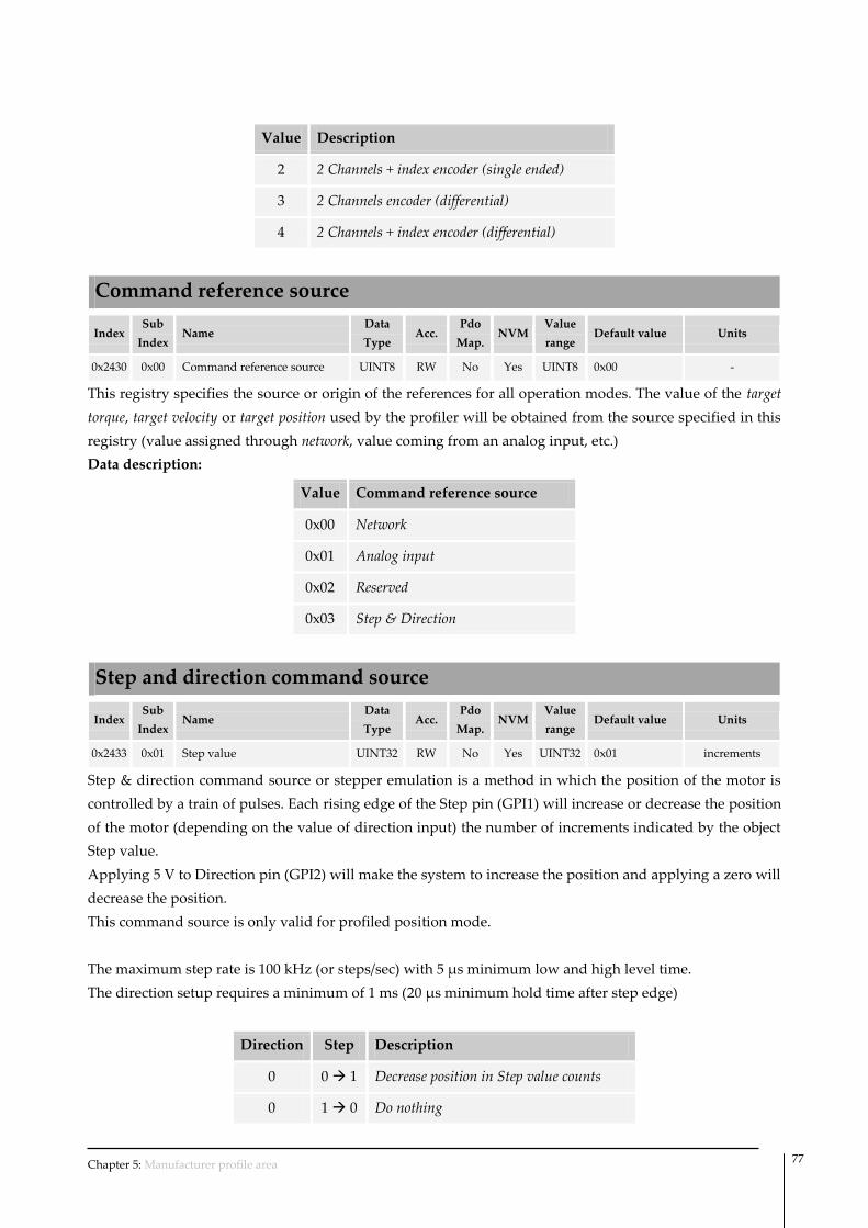
Chapter 5: Manufacturer profile area 77
Value Description
2 2 Channels + index encoder (single ended)
3 2 Channels encoder (differential)
4 2 Channels + index encoder (differential)
Command reference source
Index Sub
Index Name
Data
Type Acc.
Pdo
Map. NVM
Value
range Default value Units
0x2430 0x00 Command reference source UINT8 RW No Yes UINT8 0x00 -
This registry specifies the source or origin of the references for all operation modes. The value of the target
torque, target velocity or target position used by the profiler will be obtained from the source specified in this
registry (value assigned through network, value coming from an analog input, etc.)
Data description:
Value Command reference source
0x00 Network
0x01 Analog input
0x02 Reserved
0x03 Step & Direction
Step and direction command source
Index Sub
Index Name
Data
Type Acc.
Pdo
Map. NVM
Value
range Default value Units
0x2433 0x01 Step value UINT32 RW No Yes UINT32 0x01 increments
Step & direction command source or stepper emulation is a method in which the position of the motor is
controlled by a train of pulses. Each rising edge of the Step pin (GPI1) will increase or decrease the position
of the motor (depending on the value of direction input) the number of increments indicated by the object
Step value.
Applying 5 V to Direction pin (GPI2) will make the system to increase the position and applying a zero will
decrease the position.
This command source is only valid for profiled position mode.
The maximum step rate is 100 kHz (or steps/sec) with 5 μs minimum low and high level time.
The direction setup requires a minimum of 1 ms (20 μs minimum hold time after step edge)
Direction Step Description
0 0 1 Decrease position in Step value counts
0 1 0 Do nothing

Chapter 5: Manufacturer profile area 78
Direction Step Description
1 0 1 Increase position in Step value counts
1 1 0 Do nothing
Analog input command source
Index Sub
Index Name
Data
Type Acc.
Pdo
Map. NVM
Value
range Default value Units
0x2434 0x01 Analog input used UINT8 RW No Yes UINT8 0x01 -
0x2434 0x02 Analog input offset UINT16 RW No Yes UINT16 1024 ADC counts
0x2434 0x03 Velocity deadband UINT8 RW No Yes UINT8 1 %
When using an analog input command source and working in Profile position mode the Software position
limit register will be used as limits of the system. Therefore, the min voltage in the analog input will
correspond to a Target position of Min. Software position limit, and the max voltage will correspond to a
Max. Software position limit.
When working in Profile velocity mode the Max motor speed will be used as the maximum value of the
system and the same value but with opposite sign for the minimum value of the system.
When working in Profile torque mode the Max torque will be used as the maximum value of the system
and the same value but with opposite sign for the minimum value of the system.
SubIndex description:
0x01 (Analog input used): This object provides control to assign which analog input is used as
analog command source. The valid value for analog input used goes from 1 to the number of
analog inputs of the controller. Note that the number of analog inputs is hardware dependant.
0x02 (Analog input offset): This object sets the offset or reference of the analog input used. This is
the value in which the analog command source is considered to be in the middle of the range.
0x03 (Velocity deadband): This object allows defining a deadband of values when analog input is
used as Command reference source in Profile velocity mode.
If the difference between the value of the input and the analog input offset (value of the midpoint
of the analog range) is smaller than deadband value, the input will be considered null. This
characteristic allows reducing sensitivity at low speeds.
This registry is expressed in percentage of the analog input range, thus for example in 0 to 5V
analog input range; if the registry takes a value of 10, it will correspond to 10% of 5V and therefore
to a dead zone 0.5V around 2.5V. In the same way in -10 to 10V analog input range, it will
correspond to 2V.

Chapter 5: Manufacturer profile area 79
System polarity
Index Sub
Index Name
Data
Type Acc.
Pdo
Map. NVM
Value
range Default value Units
0x2400 0x00 System polarity UINT8 RW No Yes UINT8 0x00 -
This register makes possible to modify the system polarity, or in other words, to assign the direction of the
movement references. Depending on the polarity value, movement in one direction will be considered to
be positive or negative.
The system polarity is used in all modes. As the direction of torque, velocity and position could be changed
it allows reversing the direction of a system without modifying any cabling.
Data description:
Value Polarity
0x00 Normal polarity
0xFF Reversed polarity
Position control parameters set
Index Sub
Index Name
Data
Type Acc.
Pdo
Map. NVM
Value
range Default value Units
0x2500 0x01 Proportional constant UINT32 RW No Yes UINT32 4000 -
0x2500 0x02 Integral constant UINT32 RW No Yes UINT32 50 -
0x2500 0x03 Derivative constant UINT32 RW No Yes UINT32 0 -
0x2500 0x04 Reserved UINT32 RW No Yes UINT32 - -
0x2500 0x05 Velocity feedforward constant UINT32 RW No Yes UINT32 0 -
0x2500 0x06 Acceleration feedforward
constant UINT32 RW No Yes UINT32 0 -
0x2500 0x07 Integral limit UINT32 RW No Yes UINT32 10 -
The filter implemented in the position control loop is a parallel PID with acceleration and velocity
feedforward and also with antiwindup control based on the limited integrator. The Figure 18 shows a
diagram of the loop.

Chapter 5: Manufacturer profile area 80
+pdemand
ep
Tdemand
Saturation
preal
Kd’+
Ki’
Kp’
S
Limited 1/S
+
Kffv’
Kffa’
Vdemand
ademand
Figure 18: Position control loop
The equivalent equation of control loop is the following one:
')(')())((
')(')(')(0
ffademandffvdemand
p
d
t
pippdemand KtaKtvd
edKdeKteKtT
The integral of the error will be accumulated only within a certain limits configurable by means of the
integral limit constant. Once the accumulated error reaches this limit, the system will stop increasing the
integral.
The equation could be expressed in digital space as following:
']['][])1[][(
'][']['][0
ffademandffvdemand
sampling
pp
d
n
i
psamplingippdemand KnaKnvT
neneKieTKneKnT
The simplified equivalent equation of the implemented PID (without feedforwards) considering that the
accumulated error is limited is:
sampling
pp
dsamplingippdemandT
neneKAccuTKneKnT
])1[][('']['][ int
Where:
n
i
p
n
i
p
n
i
p
n
i
p
ieIieI
IIie
IIie
Accu
00
limlim
limlim
0
limlim
0
int
][][
][
][
The accumulated error (intAccu ) as well as the integral contribution to the total Torque demand
( int' AccuTK samplingi ) could be monitored using Position control monitor register.

Chapter 5: Manufacturer profile area 81
Due to optimization of computational time we consider the Tsampling included into the constants value. We
also include an additional scaling value to give more resolution. Therefore, the constants used sent to the
controller will be related with the internal ones in the following way:
valuesffaffa
valuesffvffv
values
sampling
d
valuessamplingii
valuespp
KKK
KKK
KT
K
dK
KTKK
KKK
'
'
'
'
'
Where
sT
K
sampling
values
001.0
65536
Giving a final scaling of
'65536
'65536
'65536000
'536.65
'65536
ffaffa
ffvffv
dd
i
pp
KK
KK
KK
KiK
KK
The integral limit could be a value between 0 (integral part disabled) and 268435456. This value represents
the maximum allowed accumulated error expressed in counts.
So, if we want a constant Kp’ with a 0.4 value we must set a 26214 into object 0x2500 subindex 1 that
corresponds to the Kp constant in position loop.
This object defines the constants of the position control loop.
Proportional part
The proportional part consists in the product between the error signal and the proportional constant (Kpp).
This component plays an important role when the error signal is large, but its action is reduced as the
signal decreases. The consequence of this effect is the appearance of a permanent error, which means the
proportional part never actually solves the system error completely.
The proportional constant will determine the permanent error, being less when the proportional constant is
bigger. Sufficiently high proportional constant values can be established to render the permanent error
almost null, but in most cases these values will only be optimum in a particular portion of the total control
range, with the optimum values being different for each portion of the range. A limit does also exist
however in the proportional constant, after which the system will in some cases reach values greater than
those desired. This phenomenon is called overshoot, and must not exceed 30% for safety reasons, although
it is desirable for the proportional part not to produce any overshoot at all.

Chapter 5: Manufacturer profile area 82
The proportional part does not consider time, so the best way to solve the
permanent error and to make the system contain some component that
considers the variation with respect to time is by including and configuring
integral and derivative actions
Integral part
The purpose of the integral part is to reduce and remove the stationary status error, caused by the
proportional mode.
The error is integrated, with the function of averaging it or adding it for a particular period of time; the
maximum accumulated error could be controlled by means of the integral limit to avoid windup effects
and also to reduce the reaction time after a disturbance. The result of the integration is then multiplied by
the Kpi integration constant. The integral reply is then added to the proportional mode, with the aim of
obtaining a stable response from the system without any stationary error.
Derivative part
The derivative action is shown when there is a change in the absolute error value (if the error is constant,
only the proportional and integral modes act).
The function of the derivative action is to keep the error to a minimum by correcting it in proportion to the
same velocity at which it occurs; this thereby prevents the error from increasing.
A greater derivative action corresponds to faster change capacity by the controller. Derivative action is
suitable when there is a load change, for example, and we cannot wait for the integral action to correct the
error by itself.
Position control monitor
Index Sub
Index Name
Data
Type Acc.
Pdo
Map. NVM
Value
range Default value Units
0x2504 0x01 Integral part INT32 RW No No INT32 - -
0x2504 0x02 Integral contribution INT32 RW No No INT32 - -
This object gives reading access to internal variables of the Position control loop to allow a better tuning of
the loop.
This register shows the value of the total accumulated error computed by the position control loop.
This register shows the contribution of the integral part to the total output of the position control loop.
Flux control parameters set
Index Sub
Index Name
Data
Type Acc.
Pdo
Map. NVM
Value
range Default value Units
0x2502 0x01 Proportional constant UINT16 RW No Yes UINT16 1638 -
0x2502 0x02 Integral constant UINT16 RW No Yes UINT16 328 -

Chapter 5: Manufacturer profile area 83
The implement filter for flux control is a parallel PI where inputs values are expressed in thousands of
motor rated torque/current, as the one shown in Figure 19.
+0ef
Vddemand
Fest
+
Ki’
Kp’
1/S
+
Figure 19: Flux control loop
The equivalent equation of control loop is the following one:
t
titpdemand deKteKtVd0
)(')(')(
The equation could be expressed in digital space as following:
n
i
tsamplingitpdemand ieTKneKnVd0
][']['][
Where sTsampling 0001.0
n
i
titpdemand ieKneKnVd0
][''][''][
'''
'''
isamplingi
pp
KTK
KK
Finally a scaling is applied with N = 8. Therefore, the equation could be expressed as follows:
n
i
titpdemand ieKneKnVd0
][][][
Where:
N
isampling
i
N
p
p
KTK
KK
2
'2
2
'2
15
15
The constants Kp’, Ki’ used in the loop must be multiplied by a 16 factor in order to obtain the value of the
emcl registers.
This object defines the constants of the flux control loop (direct current).
For further information about meaning of each parameter see Position
control parameters set.
Torque control parameters set
Index Sub
Index Name
Data
Type Acc.
Pdo
Map. NVM
Value
range Default value Units
0x2501 0x01 Proportional constant UINT16 RW No Yes UINT16 1638 -

Chapter 5: Manufacturer profile area 84
0x2501 0x02 Integral constant UINT16 RW No Yes UINT16 328 -
The implement filter for torque control is a parallel PI where inputs values are expressed in thousands of
motor rated torque/current, as the one shown in Figure 20.
+Tdemand
et
Vqdemand
Test
+
Ki’
Kp’
1/S
+
Figure 20: Torque control loop
The equivalent equation of control loop is the following one:
t
titpdemand deKteKtVq0
)(')(')(
The equation could be expressed in digital space as following:
n
i
tsamplingitpdemand ieTKneKnVq0
][']['][
Where sTsampling 0001.0
n
i
titpdemand ieKneKnVq0
][''][''][
'''
'''
isamplingi
pp
KTK
KK
Finally a scaling is applied with N = 8. Therefore, the equation could be expressed as follows:
n
i
titpdemand ieKneKnVq0
][][][
Where
N
isampling
i
N
p
p
KTK
KK
2
'2
2
'2
15
15
The constants Kp’, Ki’ used in the loop must be multiplied by a 16 factor in order to obtain the value of the
emcl registers (Kp, Ki).
This object defines the constants of the torque control loop (quadrature current).
For further information about meaning of each parameter see Position
control parameters set.
Current A
Index Sub
Index Name
Data
Type Acc.
Pdo
Map. NVM
Value
range Default value Units
0x2601 0x00 Current A INT16 RW No Yes INT16 - ADC counts

Chapter 5: Manufacturer profile area 85
This object provides the instantaneous value of the current passing through phase A.
The relationship between counts and current is as follows:
gsenAmplifier
bitsADC RGaincountiAi
sin
11
2
3)()(
Where bitsADC is 12 for DC/Voice coil motors and 10 for BLAC, and AmplifierGain and gsenR sin are
hardware specific.
Current B
Index Sub
Index Name
Data
Type Acc.
Pdo
Map. NVM
Value
range Default value Units
0x2602 0x00 Current B INT16 RW No Yes INT16 - ADC counts
This object provides the instantaneous value of the current passing through phase B.
The relationship between counts and current is as follows:
gsenAmplifier
bitsADC RGaincountiAi
sin
11
2
3)()(
Where bitsADC is 12 for DC/Voice coil motors and 10 for BLAC, and AmplifierGain and gsenR sin are
hardware specific.
Current C
Index Sub
Index Name
Data
Type Acc.
Pdo
Map. NVM
Value
range Default value Units
0x2603 0x00 Current C INT16 RW No Yes INT16 - ADC counts
This object provides the instantaneous value of the current passing through phase C.
The relationship between counts and current is as follows:
gsenAmplifier
bitsADC RGaincountiAi
sin
11
2
3)()(
Where bitsADC is 12 for DC/Voice coil motors and 10 for BLAC, and AmplifierGain and gsenR sin are
hardware specific.
Current direct
Index Sub
Index Name
Data
Type Acc.
Pdo
Map. NVM
Value
range Default value Units
0x2604 0x00 Current direct INT16 RW No Yes INT16 - ADC counts
This object provides the instantaneous direct current (current in rotational frame), which is the responsible
of the flux creation in the motor.
The relationship between counts and current is as follows:
gsenAmplifier
bitsADC RGaincountiAi
sin
11
2
3)()(

Chapter 5: Manufacturer profile area 86
Where bitsADC is 12 for DC/Voice coil motors and 10 for BLAC, and AmplifierGain and gsenR sin are
hardware specific.
Current quadrature
Index Sub
Index Name
Data
Type Acc.
Pdo
Map. NVM
Value
range Default value Units
0x2605 0x00 Current quadrature INT16 RW No Yes INT16 - ADC counts
This object provides the instantaneous quadrature current (current in rotational frame), which is the
responsible of the torque creation in the motor.
The relationship between counts and current is as follows:
gsenAmplifier
bitsADC RGaincountiAi
sin
11
2
3)()(
Where bitsADC is 12 for DC/Voice coil motors and 10 for BLAC, and AmplifierGain and gsenR sin are
hardware specific.
Dedicated digital input
Index Sub
Index Name
Data
Type Acc.
Pdo
Map. NVM
Value
range Default value Units
0x2A01 0x01 Polarity UINT16 RW No Yes UINT16 0 -
0x2A01 0x02 Value UINT16 RW No No UINT16 - -
This object allows to set the polarity of dedicated inputs as well as to read its content.
The binary representation of the register value and its corresponding meaning is as follows:
Bit number 15 14 13 12 11 10 9 8 7 6 5 4 3 2 1 0
X X X X HALL1 HALL2 HALL3 X X ENCA ENCB ENCZ X X X X
In the polarity SubIndex a logical “1” in bit means that the pin is active at high level.
A logical “1" in the input value represents that the pin is active.
General digital input / output
Index Sub
Index Name
Data
Type Acc.
Pdo
Map. NVM
Value
range Default value Units
0x2A02 0x01 Polarity UINT16 RW No Yes UINT16 0xF -
0x2A02 0x02 Value UINT16 RW No No UINT16 - -
This object allows to assign the polarity of the input/output digital general purpose pins, as well as to
read/write their values.
The binary representation of the register value and its corresponding meaning is as follows:
Bit number: 15 14 13 12 11 10 9 8 7 6 5 4 3 2 1 0
X X X X X X X X GPI4 GPI3 GPI2 GPI1 GPO4 GPO3 GPO2 GPO1

Chapter 5: Manufacturer profile area 87
In the polarity SubIndex a logical “1” in bit means that the pin is active at high level.
A logical “1" in the input value represents that the pin is active.
Analog inputs
Index Sub
Index Name
Data
Type Acc.
Pdo
Map. NVM
Value
range Default value Units
0x2A03 0x01 Analog input 1 value UINT32 RO Yes No UINT32 - ADC counts
0x2A03 0x02 Analog input 2 value UINT32 RO Yes No UINT32 - ADC counts
This object indicates the result of the analog to digital conversion.
The value is represented in counts of the ADC.
Not all ingenia controllers include two Analog inputs. Please refer to
Installation manual for further information.
SubIndex description:
0x01 (Analog input 1 value): This object will return the result of the ADC for analog input 1 which
has a 0 to 5 V range. As the ADC has 12 bits of resolution, a value of 0 V will be translated to 0
counts and a value of 5 V will be translated to 4095 counts. An analog input out of 0 to 5 V range
but within the admissible voltage range will saturate the ADC output giving 0 or 4096 counts.
An analog input out of the admissible voltage range could destroy the
controller. Please refer to controller product manual for further information
about the admissible voltages.
0x02 (Analog input 2 value): This object will return the result of the ADC for analog input 2 which
has a -10 to 10 V range. As the ADC has 12 bits of resolution, a value of -10 V will be translated to 0
counts and a value of 12 V will be translated to 4095 counts. An analog input out of -10 V to 10 V
range but within the admissible voltage range will saturate the ADC output giving 0 or 4095
counts.
An analog input out of the admissible voltage range could destroy the
controller. Please refer to controller product manual for further information
about the admissible voltages.
Analog outputs
Index Sub
Index Name
Data
Type Acc.
Pdo
Map. NVM
Value
range Default value Units
0x2A04 0x01 Analog output 1 value UINT32 RW No No UINT32 0 DAC counts
0x2A04 0x02 Analog output 2 value UINT32 RW No No UINT32 0 DAC counts
This object allows to assign the value be converted by means of the Digital to Analog Converter (DAC).
SubIndex 0x01 is used in 10 bits version of the DAC and SubIndex 0x02 is used in 16 bits version.

Chapter 5: Manufacturer profile area 88
The value is represented in counts of the ADC.
Not all ingenia controllers include a 16 bit Analog output. Please refer to
Installation manual for further information.
SubIndex description:
0x01 (Analog output 1 value): This object is used to set the value of the analog output 1 which has
a resolution of 10 bits and 0 to 5 V voltage range. A value of 0 in the object will generate 0 V, a
value of 1023 or higher will generate 5 V.
0x02 (Analog output 2 value): This object is used to set the value of the analog output 1 which has
a resolution of 16 bits and 0 to 10 V voltage range. A value of 0 in the object will generate 0 V, a
value of 65535 will generate 10 V. A value higher than 65535 will wrap automatically to the other
end of the range.
Analog output automatic
Index Sub
Index Name
Data
Type Acc.
Pdo
Map. NVM
Value
range Default value Units
0x2A08 0x01 Mode enabled UINT8 RW No Yes 0-1 0 -
0x2A08 0x02 Source register INT32 RW No Yes INT32 0x6074 -
0x2A08 0x03 Destination output UINT8 RW No Yes 1-2 1 -
0x2A08 0x04 Max represented value UINT32 RW No Yes UINT32 0x7FFFFFFF -
This object allows to assign automatically the content of an object to an analog output.
The value of the automatically generated analog output will depend of the selected source register data
type and of Max represented value object:
If the assigned object has a signed range of valid values, the analog output will be offset
automatically to the middle of its range and will be scaled to a range from -Max represented value
to +Max represented value. Therefore, maximum DAC output value will correspond to an input of
Max represented value or higher. Minimum DAC output value will correspond to an input of -Max
represented value or smaller. A zero input value will be represented by DAC middle range.
If the assigned object has an unsigned range of valid values, the analog output will be centered to
minimum DAC output value and scaled to a range from 0 to Max represented value. A zero input
value will be represented by a minimum DAC output.
SubIndex description:
0x01 (Mode enabled): This object is used to activate/deactivate to automatic mode. Setting a 1 will
enable the mode and setting a 0 will disable it.
0x02 (Source register): Select the source values of the automatic analog output mode. It should be
expressed as a combination of the subindex and index value (i.e. to select the subindex 0x02 of
register 0x2C00, the 0x022C00 value should be written).
0x03 (Destination output): Select which of the analog outputs should be used for the automatic
mode.

Chapter 5: Manufacturer profile area 89
Not all ingenia controllers include a 16 bit Analog output. Please refer to
Installation manual for further information.
0x04 (Max represented value): Indicates the range of represented values by the analog output.
Pointer access
Index Sub
Index Name
Data
Type Acc.
Pdo
Map. NVM
Value
range Default value Units
0x2C09 0x01 Pointer to register INT32 RW No No INT32 0 -
0x2C09 0x02 Content of register INT32 RW No No INT32 0 -
0x2C09 0x03 Write content to register INT32 RW No No INT32 0 -
This object provides access to registers using indirect addressing by means of a pointer.
SubIndex description:
The pointer object is divided into three parts:
0x01 (Pointer to register): This entry contains the address or object number where the pointer is
addressing (i.e. Writing a 0x6040 indicates that the pointer is addressing at the Controlword
object).
0x02 (Content of register): Using this entry the content where the pointer addresses could be read
or modified (i.e. If the pointer addresses to 0x6040, reading this entry will return the content of the
Controlword object).
0x03 (Writing content to register): Using this entry the content where the pointer addresses is
saved in the object passed as parameter. (i.e. If the pointer addresses to 0x6040, writing a 0x22C00
into this entry will directly copy the content of the Controlword into the W2 register).
Reset device
Index Sub
Index Name
Data
Type Acc.
Pdo
Map. NVM
Value
range Default value Units
0x2FFF 0x00 Reset device UINT32 RW No No UINT32 0 -
This object forces a software reset of the device. After this command is executed the content of the volatile
memory will be lost as a power-down power-up sequence does. Phasing of the system will be lost and
Macro 0 will be executed again.
In order to avoid accidentally resets of the device, this function is only executed when a specific signature
is written the appropriate sub-index. The signature that must be written is "rstd":
MSB LSB
d t s r
0x64 0x74 0x73 0x72

Chapter 5: Manufacturer profile area 90
5.2 i2t Protection
The energy dissipated by a motor is defined as:
tRitPE RMSsystem 2
Where RMSi is the RMS current flowing through the motor and R is its resistance.
The nominal current that can flow through the motor is determined by the power it can dissipate
continuously without exceeding its thermal limits.
tRiE nomRMSnomsystem 2
__
In a transient peak, the motor could tolerate an excess of energy with respect to continuous limit. The
excess of energy could be expressed as follows:
tRitRiE nomRMSpeakRMStrans 2
_
2
_
Most times we know the current rating system, the peak current and the maximum duration of the peak.
Therefore, the equation could be simplified as follows:
tiiR
EE nomRMSpeakRMS
transexcess
2
_
2
_
This excess of energy is called I-squared-t ( ti 2) and it is expressed in amper2 per second.
peaknomRMSpeakRMS tiiti 2
_
2
_
2
The following picture shows a graphical representation of the i2t limit algorithm implemented in the
controller. In the left side of the graph the system is working with its nominal current. Under this situation
the system could be infinite time. Once the actual current crosses the motor nominal current the algorithm
starts to integrate the excess of energy (red zone). If the excess of energy reach the prefixed value it will
decrease the current to the nominal one and will generate an interrupt. Once the system has started to limit
it will not allow new overcurrent peaks until the ti 2accumulated goes below half of its maximum allowed
value.

Chapter 5: Manufacturer profile area 91
Current (A)
Time (s)
Nominal
Peak
Peak time
i2t limit
continuous
Figure 1 : i2t algorithm
For example, if the system is configured with the following parameters:
Ai nomRMS 1_
Ai peakRMS 2_
st peak 1
The i2t variable or energy excess will have the following value:
sAtiiti peaknomRMSpeakRMS 32
_
2
_
2
It means that the system will tolerate a peak of 2A during 1s but also some other combinations like for
example:
Ai nomRMS 1_
Ai peakRMS 5,1_
sAtiiti peaknomRMSpeakRMS 32
_
2
_
2 st peak 4,2
The system will not allow new overcurrent peak until the energy excess goes below sAti 5,12
2
i2t parameters
Index Sub
Index Name
Data
Type Acc.
Pdo
Map. NVM
Value
range Default value Units
0x2702 0x01 Peak current UINT16 RW No Yes UINT16 1000 ‰ rated current
0x2702 0x02 Peak time UINT16 RW No Yes UINT16 1000 milliseconds
This object allows configuring the i2t algorithm for the motor.
The peak current is given in per thousand of rated current and should be higher than 1000 to activate the
algorithm. It is expressed in RMS.
Please, note that Max current, Max torque, Positive torque limit value and
Negative torque limit value objects should not limit the peak current.

Chapter 5: Manufacturer profile area 92
5.3 Macros
Command instructions can be entered directly and executed immediately, but emcl also has the capability
of using commands to form other commands called "macros". These macros are stored in the nonvolatile
memory (NVM) and can be executed automatically.
Macros are created by stringing together one command with argument and indicating where they have to
be stored. The emcl allows for the creation of 64 macros of 64 commands or instruction each.
emcl also incorporates some general purpose registers as well as some arithmetic and sequence commands
to giving a high level of programming capabilities.
All Macros should be terminated with a Return from macro call instruction.
Macro number ‘0’ will be always automatically executed after power-up.
General purpose registers
Index Sub
Index Name
Data
Type Acc.
Pdo
Map. NVM
Value
range Default value
0x2C00 0x01 Accumulator (ACCUM) INT32 RW No No INT32 0
0x2C00 0x02 W2 INT32 RW No No INT32 0
0x2C00 0x03 W3 INT32 RW No No INT32 0
… … … … … … … … …
0x2C00 0x54 W84 INT32 RW No No INT32 0
0x2C00 0x55 W85 INT32 RW No Yes INT32 0
… … … … … … … … …
0x2C00 0x64 W100 INT32 RW No Yes INT32 0
This object provides access to a general purpose RAM memory space that could be used to store
temporally parameters, to perform operations, etc. The access is done through working registers whose
size is an INTEGER32.
There are a total of 100 registers available. First one is called Accumulator (ACCUM) and the next ones are
called Wx where x represents the SubIndex.
The registers from W85 to W100 could be saved into Non-volatile memory using Store parameters register.
Please note that ACCUM and W2 are special registers used by operations like
multiplication or division and therefore its content could change once of
these operations are executed.
Wherever ACCUM register is modified a sign extension of its value is
applied to W2.

Chapter 5: Manufacturer profile area 93
Register commands
Index Sub
Index Name
Data
Type Acc.
Pdo
Map. NVM
Value
range Function brief
0x2C01 0x01 Add constant to accumulator INT32 WO No No INT32 ACCUM = ACCUM + constant
0x2C01 0x02 Accumulator divide constant INT32 WO No No INT32 [W2:ACCUM] = [W2:ACCUM] /
constant
0x2C01 0x03 Xor constant to accumulator INT32 WO No No INT32 ACCUM = ACCUM XOR constant
0x2C01 0x04 Accumulator multiply constant INT32 WO No No INT32 [W2:ACCUM ]= [W2:ACCUM] *
constant
0x2C01 0x05 And constant to accumulator INT32 WO No No INT32 ACCUM = ACCUM AND constant
0x2C01 0x06 Or constant to accumulator INT32 WO No No INT32 ACCUM = ACCUM OR constant
0x2C01 0x07 Subtract constant from
accumulator INT32 WO No No INT32 ACCUM = ACCUM - constant
0x2C01 0x08 Shift left accumulator by
constant INT32 WO No No INT32 ACCUM = ACCUM << constant
0x2C01 0x09 Shift right accumulator by
constant INT32 WO No No INT32 ACCUM = ACCUM >> constant
0x2C01 0x0A Add register to accumulator INT32 WO No No INT32 ACCUM = ACCUM + register
0x2C01 0x0B Accumulator divide register INT32 WO No No INT32 [W2:ACCUM] = [W2:ACCUM] /
register
0x2C01 0x0C Xor register to accumulator INT32 WO No No INT32 ACCUM = ACCUM XOR register
0x2C01 0x0D Accumulator multiply register INT32 WO No No INT32 [W2:ACCUM] =[W2:ACCUM ]*
register
0x2C01 0x0E And register to accumulator INT32 WO No No INT32 ACCUM = ACCUM AND register
0x2C01 0x0F Or register to accumulator INT32 WO No No INT32 ACCUM = ACCUM OR register
0x2C01 0x10 Substract register from
accumulator INT32 WO No No INT32 ACCUM = ACCUM - register
0x2C01 0x11 Shift left accumulator by
register INT32 WO No No INT32 ACCUM = ACCUM << register
0x2C01 0x12 Shift right accumulator by
register INT32 WO No No INT32 ACCUM = ACCUM >> register
0x2C01 0x13 Absolute accumulator INT32 WO No No INT32 ACCUM = |ACCUM |
0x2C01 0x14 Accumulator complement INT32 WO No No INT32 ACCUM = NOT(ACCUM )
0x2C01 0x15 Write accumulator to register INT32 WO No No INT32 register = ACCUM
0x2C01 0x16 Write register32 to accumulator INT32 WO No No INT32 ACCUM = register32
0x2C01 0x17 Write register16 to accumulator INT32 WO No No INT32 ACCUM = register16
This object provides access to a set of arithmetic operators that could be used with general purpose
registers.

Chapter 5: Manufacturer profile area 94
SubIndex description:
All arithmetic uses signed 32 bit values except multiplication and division that produce or use
signed 64 bits values. A signed 64 bits value is stored in W2 and ACCUM (the upper 32 bits in W2
and the lower 32 bits in ACCUM)
Multiplication multiplies the 32 bits signed value in ACCUM by a signed 32 bits value (constant or
register contents) with as result a 64 bits signed value in W2 and ACCUM.
Division divides the signed 64 bits value in W2 and ACCUM by a signed 32 bits value (constant or
register contents) with as result a 64 bits signed value in W2 and ACCUM.
Logic operators (AND, OR, XOR, shift and complement) are bitwise operators.
Shift operations shift the contents of the accumulator in the indicated direction the given number of
bits (constant of register contents). The new bits will be filled with zero.
Sequence commands
Index Sub
Index Name
Data
Type Acc.
Pdo
Map. NVM
Value
range Function brief
0x2C02 0x01 Do if i/o is “Off” INT32 WO No No INT32
0x2C02 0x02 Do if i/o is “On” INT32 WO No No INT32
0x2C02 0x03 End program INT32 WO No No INT32
0x2C02 0x04 If accumulator is below value INT32 WO No No INT32 If ACCUM < constant
0x2C02 0x05 If accumulator is higher value INT32 WO No No INT32 If ACCUM > constant
0x2C02 0x06 If accumulator is equal value INT32 WO No No INT32 If ACCUM = constant
0x2C02 0x07 If accumulator is unequal value INT32 WO No No INT32 If ACCUM <> constant
0x2C02 0x08 If i/o is “Off” INT32 WO No No INT32
0x2C02 0x09 If i/o is “On” INT32 WO No No INT32
0x2C02 0x0A If bit of accumulator is set INT32 WO No No INT32 If bit of ACCUM = 1
0x2C02 0x0B If bit of accumulator is clear INT32 WO No No INT32 If bit of ACCUM = 0
0x2C02 0x0C Repeat INT32 WO No No INT32
0x2C02 0x0D Wait (milliseconds) INT32 WO No No INT32
0x2C02 0x0E Wait for Index INT32 WO No No INT32
0x2C02 0x0F Wait for i/o to be “Off” INT32 WO No No INT32
0x2C02 0x10 Wait for i/o to be “On” INT32 WO No No INT32
0x2C02 0x11 If analog is below INT32 WO No No INT32 If ANALOG1 < constant
0x2C02 0x12 If analog is higher INT32 WO No No INT32 If ANALOG1 > constant
0x2C02 0x13 If accumulator is below register INT32 WO No No INT32 If ACCUM < register
0x2C02 0x14 If accumulator is higher register INT32 WO No No INT32 If ACCUM > register
0x2C02 0x15 If accumulator is equal register INT32 WO No No INT32 If ACCUM = register
0x2C02 0x16 If accumulator is unequal
register INT32 WO No No INT32 If ACCUM <> register

Chapter 5: Manufacturer profile area 95
This object gives access to a set of command that provide for conditional sequence execution, based on
register data, input/output, etc.
In commands that use input/output the channel used will correspond directly to the General input pin (i.e.
if we want to use the general digital input number 1 we must use the channel 1, for input number 2 we will
use channel 2 and so on).
SubIndex description:
These sequence commands are illustrated by the following general forms:
DO: If the condition is true, command execution will continue normally. If the condition is false,
the rest of macro will be skipped.
IF: If the condition is true, command execution will continue normally. If the condition is false, the
next macro command will be skipped.
WAIT: If the condition is true, command execution will continue normally. If the condition if false,
macro execution will be suspended until the condition becomes true.
REPEAT: This command causes the macro to be repeated the number of times specified by the
value passed as parameter. If parameter is "0", the macro is repeated indefinitely.
Macro commands
Index Sub
Index Name
Data
Type Acc.
Pdo
Map. NVM
Value
range Default value
0x2C04 0x01 Macro call INT32 WO No No INT32 -
0x2C04 0x02 Return from macro call INT32 WO No No INT32 -
0x2C04 0x03 Macro jump INT32 WO No No INT32 -
0x2C04 0x04 Reset macro INT32 WO No No INT32 -
0x2C04 0x05 Jump absolute INT32 WO No No INT32 -
0x2C04 0x06 Jump relative INT32 WO No No INT32 -
0x2C04 0x07 Unpush macro INT32 WO No No INT32 -
This object provides access to a set of command that provide execution and jumps between different
macros.
SubIndex description:
0x01 (Macro call): This command allows a previously defined macro specified by the parameter to
be called like a subroutine. When this command is used, the current macro being executed is
pushed to the macro stack and execution of new macro begins. If macro has not been defined, then
an error will be reported. After execution of the defined macro, command execution will continue
immediately after the Macro Call command. The Macro Call command can be used any place in a
macro.
Macro calls via the Macro Call command or the interrupt system, may be
nested up to 7 calls deep.

Chapter 5: Manufacturer profile area 96
0x02 (Return from a macro call): When executed, this command will cause immediate return to the
calling macro (assuming there was one). All macros should finish with this command to avoid
unexpected results. The parameter is not used by the command but is necessary to maintain the
same structure of other commands.
0x03 (Macro jump): This command may be used to "Jump" to another macro. Once the emcl begins
executing the new macro, it has no record of how it got there. This means that any commands that
appear after the Macro Jump command will not be executed. If there is no macro defined by the
number specified in the parameter, an error will be reported. Once the end of the macro is
encountered, macro execution stops. It is also acceptable for a macro to jump to itself.
0x04 (Reset macro): This command is used to delete one macro. The macro specified by the
argument will be deleted and the memory it uses will be lost. A Reset Macro command should be
used before entering or downloading a new set of macro commands.
A reset macro command must be followed by a 500 msec delay before the
next command can be sent to the controller.
0x05 (Jump absolute): This command causes execution of a macro to jump to the absolute
command specified by the parameter. Commands are numbered sequentially starting from 0. If
parameter is specified whereas the command would attempt to jump past the end of the macro,
then an error will be reported.
0x06 (Jump relative): This command causes execution of a macro to jump to the relative command
specified by the parameter. Commands are numbered sequentially starting from 0. If parameter is
specified whereas the command would attempt to jump past the end of the macro, then an error
will be reported.
0x07 (Unpush macro): This command resets completely the actual macro call and return stack. It
could be used to abort a return from a macro interrupt function. The parameter is not used.
Macro access
Index Sub
Index Name
Data
Type Acc.
Pdo
Map. NVM
Value
range Default value
0x2C05 0x01 Macro number UINT8 RW No No UINT8 -
0x2C05 0x02 Macro command UINT8 RW No No UINT8 -
0x2C05 0x03 Command UINT64 WO No No UINT64 -
0x2C05 0x04 Protected access UINT8 RW No Yes 0-1 0
This object provides the necessary interface from saving or recovering macros into the NVM.
For normal applications Macro access is controlled by software tools like
Composer that will save the macros in NVM. The Macro access object is
needed for advanced users only.
The emcl allows for the creation of 64 macros of 64 commands or instruction each.

Chapter 5: Manufacturer profile area 97
SubIndex description:
0x01 (Macro number): Selects the desired macro to be accessed.
0x02 (Macro command): Selects the desired command within the selected macro number to be
accessed.
0x03 (Command): Read or write the command content.
To write a command into the NVM, first the macro number (SubIndex 0x01) and macro command
(SubIndex 0x02) must be fixed. Then if a valid command is written into the Subndex 0x03, it will be
saved automatically into the NVM
Data description:
The format of this command is the show below (in bytes format):
Byte number: 7 6 5 4 3 2 1 0
SubIndex
(8bits)
Index
(16bits)
Length
(4bits)
Reserved
(3bits)
R/W
(1bit)
Data
(32bits)
Where:
SubIndex and Index represents the object to be saved or read.
R/W (bit 0 of byte 4): Represents if is a reading (indicated by a 1) or writing (indicated by a 0)
process. Reading process works only in RS232 based communications.
Length (bits 7 to 4 of byte 4): Indicates the length of the register data (in bytes).
Data: Represents the data to write in the target register (only useful in writing processes). Most
significant byte first.
A read of this object will return 0xFFFFFFF1FFFFFFFF if the end of the macro is reached.
0x04 (Protected access): Activates or deactivates the macro reading protection.
To activate the protection a 1 must be written to this command. Once the protection is activated, a
reading attempt will always generate and EMCY with a “Parameter error” error code (0x6320).
Please, notice that protected access bit is automatically written in external NVM to avoid losing
protection on FW updates or restore to default processes. Therefore, is not necessary to send a Save
all parameters command after modifying the protected access object.
To deactivate the protection a 0 must be written to this command. It is only allowed to deactivate
the protection if all macros are previously reset, all attempts with some macro content in the
controller will be discarded.
Macro debug
Index Sub
Index Name
Data
Type Acc.
Pdo
Map. NVM
Value
range Default value
0x2C0A 0x01 Actual macro number UINT8 RO No No UINT8 -
0x2C0A 0x02 Actual command number UINT8 RO No No UINT8 -
This object provides information about the actual command and macro being executed or pending of
execution by the controller. As soon as an instruction is completed, the value of the debug register is
updated.

Chapter 5: Manufacturer profile area 98
5.4 Timers
Timer access
Index Sub
Index Name
Data
Type Acc.
Pdo
Map. NVM
Value
range Default value Units
0x2C06 0x01 Timer 1 (count up) value UINT32 RW No No UINT32 0 milliseconds
0x2C06 0x02 Timer 2 (count up) value UINT32 RW No No UINT32 0 milliseconds
0x2C06 0x03 Timer 3 (count down) value UINT32 RW No No UINT32 0 milliseconds
0x2C06 0x03 Timer 4 (count down) value UINT32 RW No No UINT32 0 milliseconds
emcl incorporates some real time counters available to the user.
There are two types of timer: count up and count down timer.
In the count up timer, the value of the timer is incremented every 1 ms until it reaches its maximum value
and is reset to zero. In the count down timer, the value of the timer is decremented every 1 ms until it
reaches its minimum value and is reset to maximum value.
This object provides access for reading / writing the content of the timers.
5.5 Interrupts
The emcl employs a "Macro Interrupt System" to provide additional versatility in programming the motion
controllers. This system comprises 10 interrupt sources with the corresponding vectors.
When an interrupt’s source is enabled for operation and then becomes active, the current macro being
executed is saved to a so called macro stack and execution of the macro specified by that interrupt’s vector
table entry begins. This happens to be similar procedure to that which the Macro Call command follows.
The Interrupt Vector Table consists of an entry for each interrupt source. A particular table entry must be
loaded with the number of a valid macro to be executed should that interrupt source become active.
The user must first use the Interrupt vector command to set the number of the macro for a vector. If an
interrupt is generated and that vector table entry has not been defined (equal to 0) then the interrupt will
not be executed. Note that this implies that macro "0" cannot be used as an interrupt macro.
The following table lists all the possible interrupt sources.
Interrupt vector Interrupt source Interrupt vector Interrupt source
10 Reserved 5 Timer 1 overflow
9 User i2t exceeded 4 GPI4 state enabled
8 Timer 4 underflow 3 GPI3 state enabled
7 Timer 3 underflow 2 GPI2 state enabled
6 Timer 2 overflow 1 GPI1 state enabled

Chapter 5: Manufacturer profile area 99
Interrupt vector
Index Sub
Index Name
Data
Type Acc.
Pdo
Map. NVM
Value
range Default value
0x2C07 0x01 Interrupt 1 vector UINT8 RW No No UINT8 0
0x2C07 0x02 Interrupt 2 vector UINT8 RW No No UINT8 0
0x2C07 0x03 Interrupt 3 vector UINT8 RW No No UINT8 0
0x2C07 0x04 Interrupt 4 vector UINT8 RW No No UINT8 0
0x2C07 0x05 Interrupt 5 vector UINT8 RW No No UINT8 0
0x2C07 0x06 Interrupt 6 vector UINT8 RW No No UINT8 0
0x2C07 0x07 Interrupt 7 vector UINT8 RW No No UINT8 0
0x2C07 0x08 Interrupt 8 vector UINT8 RW No No UINT8 0
0x2C07 0x09 Interrupt 9 vector UINT8 RW No No UINT8 0
0x2C07 0x0A Interrupt 10 vector UINT8 RW No No UINT8 0
This object allows assigning the called macro for each interrupt source. For example, writing a 3 into the
interrupt 5 vector will execute the macro number 3 once the timer1 overflows.
Interrupt enable
Index Sub
Index Name
Data
Type Acc.
Pdo
Map. NVM
Value
range Default value
0x2C08 0x01 Interrupt 1 enable UINT8 RW No No UINT8 0
0x2C08 0x02 Interrupt 2 enable UINT8 RW No No UINT8 0
0x2C08 0x03 Interrupt 3 enable UINT8 RW No No UINT8 0
0x2C08 0x04 Interrupt 4 enable UINT8 RW No No UINT8 0
0x2C08 0x05 Interrupt 5 enable UINT8 RW No No UINT8 0
0x2C08 0x06 Interrupt 6 enable UINT8 RW No No UINT8 0
0x2C08 0x07 Interrupt 7 enable UINT8 RW No No UINT8 0
0x2C08 0x08 Interrupt 8 enable UINT8 RW No No UINT8 0
0x2C08 0x09 Interrupt 9 enable UINT8 RW No No UINT8 0
0x2C08 0x0A Interrupt 10 enable UINT8 RW No No UINT8 0
Loading a vector table entry will not enable an interrupt for operation. The Interrupt enable command
must be used for this purpose.
When the Interrupt enable command is used, it will enable the interrupt source (specified with the
command) to function. In order to prevent multiple or continuous interrupts, as an interrupt is taken it is
automatically disabled. This means that the user must re-enable that interrupt using the Interrupt enable
command before it will occur again.
Writing a 1 to this register it will enable the interrupt and a 0 will disable it.
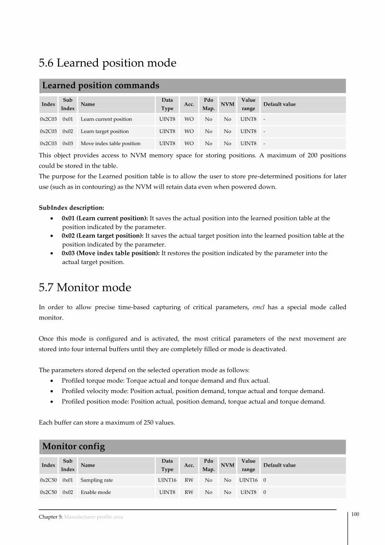
Chapter 5: Manufacturer profile area 100
5.6 Learned position mode
Learned position commands
Index Sub
Index Name
Data
Type Acc.
Pdo
Map. NVM
Value
range Default value
0x2C03 0x01 Learn current position UINT8 WO No No UINT8 -
0x2C03 0x02 Learn target position UINT8 WO No No UINT8 -
0x2C03 0x03 Move index table position UINT8 WO No No UINT8 -
This object provides access to NVM memory space for storing positions. A maximum of 200 positions
could be stored in the table.
The purpose for the Learned position table is to allow the user to store pre-determined positions for later
use (such as in contouring) as the NVM will retain data even when powered down.
SubIndex description:
0x01 (Learn current position): It saves the actual position into the learned position table at the
position indicated by the parameter.
0x02 (Learn target position): It saves the actual target position into the learned position table at the
position indicated by the parameter.
0x03 (Move index table position): It restores the position indicated by the parameter into the
actual target position.
5.7 Monitor mode
In order to allow precise time-based capturing of critical parameters, emcl has a special mode called
monitor.
Once this mode is configured and is activated, the most critical parameters of the next movement are
stored into four internal buffers until they are completely filled or mode is deactivated.
The parameters stored depend on the selected operation mode as follows:
Profiled torque mode: Torque actual and torque demand and flux actual.
Profiled velocity mode: Position actual, position demand, torque actual and torque demand.
Profiled position mode: Position actual, position demand, torque actual and torque demand.
Each buffer can store a maximum of 250 values.
Monitor config
Index Sub
Index Name
Data
Type Acc.
Pdo
Map. NVM
Value
range Default value
0x2C50 0x01 Sampling rate UINT16 RW No No UINT16 0
0x2C50 0x02 Enable mode UINT8 RW No No UINT8 0

Chapter 5: Manufacturer profile area 101
This object allows configuring the base-time as well as to activate or deactivate the mode.
SubIndex description:
0x01 (Sampling rate): It indicates the sampling rate of monitoring mode, and it is expressed in
multiples of the update loop period of the monitored variable.
For example:
o When working in profiled torque mode as the torque loop is update at 10 kHz (100 μs),
writing a 1 will take a sample every 100 μs, writing a 2 will take a sample every 200 μs
and so on.
o When working in profiled velocity or position mode as the position/velocity loops are
updates at 1 kHz (1 ms), writing a 1 will take a sample every 1 ms, writing a 2 will take
a sample every 2 ms and so on.
0x02 (Enable mode): It indicates if the mode is enabled or disabled. Writing a one will enable the
monitoring in the next movement.
Monitor result
Index Sub
Index Name
Data
Type Acc.
Pdo
Map. NVM
Value
range Default value
0x2C51 0x01 Max entry number UINT16 RO No No UINT16 250
0x2C51 0x02 Filled entry values UINT8 RO No No UINT8 0
0x2C51 0x03 Entry number UINT16 RW No No UINT16 0
0x2C51 0x04 Actual entry 1 INT32 RO No No INT32 -
0x2C51 0x05 Actual entry2 INT32 RO No No INT32 -
0x2C51 0x06 Actual entry 3 INT32 RO No No INT32 -
0x2C51 0x07 Actual entry 4 INT32 RO No No INT32 -
This object allows to consulting the results of the monitoring mode.
It indicates the maximum length of the buffers.
It indicates the number of samples actually stored in each buffer.
It indicates the entry number access pointer, which is the index of the buffers that are going to be
consulted.
It returns the value stored in the buffer 1 (the index of the buffer is selected with entry number sub-
index).
It returns the value stored in the buffer 2 (the index of the buffer is selected with entry number sub-
index).
It returns the value stored in the buffer 3 (the index of the buffer is selected with entry number sub-
index).
It returns the value stored in the buffer 4 (the index of the buffer is selected with entry number sub-
index).

Chapter 5: Manufacturer profile area 102
5.8 Spring compensation mode
In some linear applications where there is a spring attached to the motor is necessary to add a force/torque
offset as a function of the position to compensate the influence of the spring in the control loops.
Spring compensation mode allows to add a variable torque offset as a linear function of the position. The
compensation is based in two parameters: spring offset position and spring torque offset. Basically the user
indicates which is the desired torque offset at the position indicated. The controller automatically
interpolates in a linear way the added offset for other positions as shown in the following picture. Added
force/torque at zero position is always zero.
Force / Torque
Position
Spring offset
position
Torque offset
Spring torque offset
Compensation mode works for positive and negative positions.
Spring torque compensation
Index Sub
Index Name
Data
Type Acc.
Pdo
Map. NVM
Value
range Default value Units
0x2508 0x01 Spring torque offset INT16 RW No Yes INT16 0 ‰ rated torque
0x2508 0x02 Spring offset position UINT32 RW No Yes UINT32 0 increments
This object allows configuring the spring compensation mode.
SubIndex description:
0x01 (Spring toque offset): It indicates the desired increment of torque at “Spring offset position”.
0x02 (Spring offset position): It indicates the position in which the demanded torque should be
incremented by “Spring torque offset”. If spring offset position is zero, the spring compensation
mode is disabled.

Appendix A: CiA 301 object dictionary 103
Appendix A: CiA 301 object dictionary
Index
(hex)
Sub-
Index
(hex)
Description Data
type
PDO
mapp
able
Access NVM Default
value
1000 0 Device type UINT32 N RO N 0x00020192
1001 0 Error register UINT8 N RO N 0x00
1003
- Pre-defined Error Field ARRAY - - - -
0 Number of entries UINT8 N RW N 0x00
1 Standard error field UINT32 N RO N 0x00000000
2 Standard error field UINT32 N RO N 0x00000000
3 Standard error field UINT32 N RO N 0x00000000
4 Standard error field UINT32 N RO N 0x00000000
1005 0 COB-ID SYNC UINT32 N RW N 0x80
1006 0 Communication Cycle period UINT32 N RW N 0x00000000
1007 0 Sync window length UINT32 N RW N 0x00000000
1008 0 Device name STR N CONST N emcl
1009 0 Hardware version STR N CONST N See PCB
100A 0 Software version STR N CONST N 0.92B2
100C 0 Guard time UINT16 N RW N 0x0000
100D 0 Life Time Factor UINT8 N RW N 0x00
1010
- Store parameters ARRAY - - - -
0 Number of entries UINT8 N CONST N 3
1 Save all parameters UINT32 N RW N 1
2 Save communication parameters UINT32 N RW N 1
3 Save application parameters UINT32 N RW N 1
1011
- Restore default parameters ARRAY - - - -
0 Number of entries UINT8 N CONST N 3
1 Restore all parameters UINT32 N RW N 1
1 Restore communication parameters UINT32 N RW N 1
1 Restore application parameters UINT32 N RW N 1
1014 0 COB-ID Emergency message UINT32 N RW N 0x000000A0
1017 0 Producer heartbeat time UINT16 N RW N 0x0000
1018
- Identity object RECORD - - - -
0 Number of entries UINT8 N CONST N 4
1 Vendor-ID UINT32 N RO N 0x0000029C
2 Product code UINT32 N RO N 0x00000116
3 Revision number UINT32 N RO N 0x00000000
4 Serial number UINT32 N RO N -
1200 - SSDO - N RO N -
1400 - RPDO1 - N RW Y -
1401 - RPDO2 - N RW Y -

Appendix A: CiA 301 object dictionary 104
1402 - RPDO3 - N RW Y -
1403 - RPDO4 - N RW Y -
1600 - RPDO 1 mapping parameter - N RW Y -
1601 - RPDO 2 mapping parameter - N RW Y -
1602 - RPDO 3 mapping parameter - N RW Y -
1603 - RPDO 4 mapping parameter - N RW Y -
1800 - TPDO 1 - N RW Y -
1801 - TPDO 2 - N RW Y -
1802 - TPDO 3 - N RW Y -
1803 - TPDO 4 - N RW Y -
1A00 - TPDO 1 mapping parameter - N RW Y -
1A01 - TPDO 2 mapping parameter - N RW Y -
1A02 - TPDO 3 mapping parameter N RW Y -
1A03 - TPDO 4 mapping parameter N RW Y -

Appendix B: CiA 402 object dictionary 105
Appendix B: CiA 402 object dictionary
Index
(hex)
Sub-
Index
(hex)
Description Data type
PDO
mapp
able
Access NVM Default
value
603F 0 Error code UINT16 Y RO N 0x0000
6040 0 Controlword UINT16 Y RW N 0x0000
6041 0 Statusword UINT16 Y RO N -
6060 0 Modes of operation INT8 Y RW Y 1
6061 0 Modes of operation display INT8 Y RO N -
6062 0 Position demand value INT32 Y RO N -
6063 0 Position actual internal value INT32 Y RO N -
6064 0 Position actual value INT32 Y RO N -
6065 0 Following error window UINT32 Y RW Y 0xFFFFFFFF
6066 0 Following error window timeout UINT16 Y RW Y 100
6067 0 Position window UINT32 Y RW Y 100
6068 0 Position window time UINT16 Y RW Y 10
606B 0 Velocity demand value INT32 Y RO N -
606C 0 Velocity actual value INT32 Y RO N -
606D 0 Velocity window UINT16 Y RW Y 1000
606E 0 Velocity window time UINT16 Y RW Y 10
606F 0 Velocity threshold UINT16 Y RW Y 1000
6070 0 Velocity threshold time UINT16 Y RW Y 100
6071 0 Target torque INT16 Y RW N 0
6072 0 Max torque UINT16 Y RW Y 1000
6073 0 Max current UINT16 Y RW Y 400
6074 0 Torque demand INT16 Y RO N -
6075 0 Motor rated current UINT32 Y RW Y 1000
6076 0 Motor rated torque UINT32 Y RW Y 310
6077 0 Torque actual value INT16 Y RO N -
6078 0 Current actual value INT16 Y RO N -
607A 0 Target position INT32 Y RW N 0
607C 0 Home offset INT32 N RW Y 0
607D
- Software position limit ARRAY - - - -
0 Number of entries UINT8 N CONST N 2
1 Min position limit INT32 Y RW Y 0x80000000
2 Max position limit INT32 Y RW Y 0x7FFFFFFF
607E 0 Polarity UINT8 Y RW Y 0
607F 0 Max profile velocity UINT32 Y RW Y 2000000
6080 0 Max motor speed UINT32 Y RW Y 50000
6081 0 Profile velocity UINT32 Y RW Y 2000000
6083 0 Profile acceleration UINT32 Y RW Y 7000000

Appendix B: CiA 402 object dictionary 106
Index
(hex)
Sub-
Index
(hex)
Description Data type
PDO
mapp
able
Access NVM Default
value
6084 0 Profile deceleration UINT32 Y RW Y 7000000
6085 0 Quick stop deceleration UINT32 Y RW Y 7000000
6086 0 Motion profile type INT16 Y RW Y 0
6087 0 Torque slope UINT32 Y RW Y 10000
6088 0 Torque profile type INT16 Y RW Y 0
608F
- Position encoder resolution ARRAY - - - -
0 Number of entries UINT8 N CONST N 2
1 Encoder increments UINT32 Y RW Y 20000
2 Motor revolutions UINT32 Y RW Y 1
6098 0 Homing method INT8 N RW Y -2
6099
- Homing speeds ARRAY - - - -
0 Number of entries UINT8 N CONST N 2
1 Speed for switch search UINT32 N RW Y 50000
2 Speed for zero search UINT32 N RW Y 5000
609A 0 Homing acceleration UINT32 N RW Y 100000
60B2 0 Torque offset INT16 Y RW Y 0
60C5 0 Max acceleration UINT32 Y RW Y 7000000
60C6 0 Max deceleration UINT32 Y RW Y 7000000
60E0 0 Positive torque limit value INT16 Y RW Y 1000
60E1 0 Negative torque limit value INT16 Y RW Y -1000
60F4 0 Following error actual value INT32 Y RO N -
60FA 0 Control effort INT32 Y RO N -
60FC 0 Position demand internal value INT32 Y RO N -
60FF 0 Target velocity INT32 Y RW Y 0
6402 0 Motor type UINT16 Y RW Y 0x000D
6502 0 Supported drive modes UINT32 Y CONST N 0xAD
6505 0 Http drive catalog address STRING N CONST N -

Appendix C: Manufacturer specific object dictionary 107
Appendix C: Manufacturer specific object
dictionary
Index
(hex)
Sub-
Index
(hex)
Description Data type
PDO
mappa
ble
Access NVM Default
value
2000
- Uart configuration ARRAY - - - -
0 Number of entries UINT8 N CONST N 5
1 Node ID UINT8 N RW Y 32
2 Baudrate UINT8 N RW Y 0
3 Daisy chain mode UINT8 N RW Y 0
4 Base format UINT8 N RW Y 0
5 Statusword mode UINT8 N RW Y 1
2100
- Phasing RECORD - - - -
0 Number of entries UINT8 N CONST N 6
1 Phasing type UINT8 N RW Y 0
2 Phasing time UINT32 N RW Y 1000
3 Phasing current UINT32 N RW Y 500
4 Phasing tolerance UINT8 N RW Y 5
5 Phasing initial rotor position UINT16 N RW Y 0
6 Phasing actual rotor position UINT16 N RO N -
2102
- Homing extra parameters ARRAY - - - -
0 Number of entries UINT8 N CONST N 2
1 Total homing timeout UINT16 N RW Y 8000
2 Torque limit UINT16 N RW Y 200
2301 0 Motor pair poles UINT8 N RW Y 4
2311 0 Position encoder swap mode UINT8 N RW Y 1
2312 0 Position encoder type UINT8 N RW Y 2
2400 0 System polarity UINT8 N RW Y 0
2430 0 Command reference source UINT8 N RW Y 0
2433
- Step and direction command source ARRAY - - - -
0 Number of entries UINT8 N CONST N 1
1 Step value UINT32 N RW Y 1
2434
- Analog input command source RECORD - - - -
0 Number of entries UINT8 N CONST N 3
1 Analog input used UINT8 N RW Y 1
2 Analog input offset UINT16 N RW Y 512
3 Velocity deadband UINT8 N RW Y 1
2500
- Position control parameter set ARRAY - - - -
0 Number of entries UINT8 N CONST N 7
1 Proportional constant UINT32 N RW Y 4000

Appendix C: Manufacturer specific object dictionary 108
Index
(hex)
Sub-
Index
(hex)
Description Data type
PDO
mappa
ble
Access NVM Default
value
2 Integral constant UINT32 N RW Y 10
3 Derivative constant UINT32 N RW Y 400000
4 Reserved UINT32 N RW Y 0
5 Velocity feedforward constant UINT32 N RW Y 0
6 Acceleration feedforward constant UINT32 N RW Y 0
7 Integral limit UINT32 N RW Y 10
2502
- Flux control parameter set ARRAY - - - -
0 Number of entries UINT8 N CONST N 2
1 Proportional constant UINT16 N RW Y 3000
2 Integral constant UINT16 N RW Y 300
2503
- Torque control parameter set ARRAY - - - -
0 Number of entries UINT8 N CONST N 2
1 Proportional constant UINT16 N RW Y 3000
2 Integral constant UINT16 N RW Y 300
2504
- Position control monitor ARRAY - - - -
0 Number of entries UINT8 N CONST N 2
1 Integral part INT32 Y RO N -
2 Integral contribution INT32 Y RO N -
2508
- Spring torque compensation RECORD - - - -
0 Number of entries UINT8 N CONST N 2
1 Spring torque offset INT16 N RW Y 0
2 Spring offset position UINT32 N RW Y 0
2601 - Current A INT16 Y RO N -
2602 - Current B INT16 Y RO N -
2603 - Current C INT16 Y RO N -
2604 - Current Direct INT16 Y RO N -
2605 - Current Quadrature INT16 Y RO N -
2702
- I2T parameters RECORD - - - -
0 Number of entries UINT8 N CONST N 2
1 Peak current UINT16 N RW Y 1000
2 Peak time UINT16 N RW Y 1000
2A01
- Dedicated digital inputs ARRAY - - - -
0 Number of entries UINT8 N CONST N 2
1 Polarity UINT16 N RW Y 0
2 Value UINT16 N RO N -
2A02
- General digital input / output ARRAY - - -
0 Number of entries UINT8 N CONST N 2
1 Polarity UINT16 N RW Y 0
2 Value UINT16 N RO N -
2A03 - Analog inputs ARRAY - - - -

Appendix C: Manufacturer specific object dictionary 109
Index
(hex)
Sub-
Index
(hex)
Description Data type
PDO
mappa
ble
Access NVM Default
value
0 Number of entries UINT8 N CONST N 2
1 Analog input 1 value UINT32 N RO N -
2 Analog input 2 value UINT32 N RO N -
2A04
- Analog output ARRAY - - - -
0 Number of entries UINT8 N CONST N 2
1 Analog output 1 value UINT32 N RW N 0
2 Analog output 2 value UINT32 N RW N 0
2A08
- Analog output automatic RECORD - - - -
0 Number of entries UINT8 N CONST N 4
1 Mode enabled UINT8 N RW Y 0
2 Source registers INT32 N RW Y 0x6074
3 Destination output UINT8 N RW Y 1
4 Max represented value UINT32 N RW Y 0x7FFFFFFF
2C00
- General purpose registers ARRAY - - - 0
0 Number of entries UINT8 N CONST N 100
1 Accumulator INT32 N RW N 0
2 W2 INT32 N RW N 0
… … INT32 N RW N 0
54 W84 INT32 N RW N 0
55 W85 INT32 N RW Y 0
.. … INT32 N RW Y 0
64 W100 INT32 N RW Y 0
2C01
- Register commands ARRAY - - - -
0 Number of entries UINT8 N CONST N 23
1 Add constant to accumulator INT32 N WO N -
2 Accumulator divide constant INT32 N WO N -
3 Xor constant to accumulator INT32 N WO N -
4 Accumulator multiply constant INT32 N WO N -
5 And constant to accumulator INT32 N WO N -
6 Or constant to accumulator INT32 N WO N -
7 Subtract constant from accumulator INT32 N WO N -
8 Shift left accumulator by constant INT32 N WO N -
9 Shift right accumulator by constant INT32 N WO N -
A Add register to accumulator INT32 N WO N -
B Accumulator divide register INT32 N WO N -
C Xor register to accumulator INT32 N WO N -
D Accumulator multiply register INT32 N WO N -
E And register to accumulator INT32 N WO N -
F Or register to accumulator INT32 N WO N -
10 Subtract register from accumulator INT32 N WO N -

Appendix C: Manufacturer specific object dictionary 110
Index
(hex)
Sub-
Index
(hex)
Description Data type
PDO
mappa
ble
Access NVM Default
value
11 Shift left accumulator by register INT32 N WO N -
12 Shift right accumulator by register INT32 N WO N -
13 Absolute accumulator INT32 N WO N -
14 Accumulator complement INT32 N WO N -
15 Write accumulator to register INT32 N WO N -
16 Write register32 to accumulator INT32 N WO N -
17 Write register16 to accumulator INT32 N WO N -
2C02
- Sequence commands ARRAY - - - -
0 Number of entries UINT8 N CONST N 22
1 Do if i/o is "Off" INT32 N WO N -
2 Do if i/o is "On" INT32 N WO N -
3 End program INT32 N WO N -
4 If accumulator is below INT32 N WO N -
5 If accumulator is higher INT32 N WO N -
6 If accumulator is equal INT32 N WO N -
7 If accumulator is unequal INT32 N WO N -
8 If i/o is "Off" INT32 N WO N -
9 If i/o is "On" INT32 N WO N -
A If bit of accumulator is set INT32 N WO N -
B If bit of accumulator is clear INT32 N WO N -
C Repeat INT32 N WO N -
D Wait (milliseconds) constant INT32 N WO N -
E Wait for Index INT32 N WO N -
F Wait for i/o to be "Off" INT32 N WO N -
10 Wait for i/o to be "On" INT32 N WO N -
11 If analog is below INT32 N WO N -
12 If analog is higher INT32 N WO N -
13 If accumulator is below register INT32 N WO N -
14 If accumulator is higher register INT32 N WO N -
15 If accumulator is equal register INT32 N WO N -
16 If accumulator is unequal register INT32 N WO N -
2C03
- Learned position ARRAY - - - -
0 Number of entries UINT8 N CONST N 3
1 Learn current position UINT8 N WO N -
2 Learn target position UINT8 N WO N -
3 Move index table position UINT8 N WO N -
2C04
- Macro commands ARRAY - - - -
0 Number of entries UINT8 N CONST N 7
1 Macro call INT32 N WO N -
2 Return from macro call INT32 N WO N -

Appendix C: Manufacturer specific object dictionary 111
Index
(hex)
Sub-
Index
(hex)
Description Data type
PDO
mappa
ble
Access NVM Default
value
3 Macro jump INT32 N WO N -
4 Reset macros INT32 N WO N -
5 Jump absolute INT32 N WO N -
6 Jump relative INT32 N WO N -
7 Unpush macro INT32 N WO N -
2C05
- Macro access RECORD - - - -
0 Number of entries UINT8 N CONST N 4
1 Macro number UINT8 N RW N -
2 Macro command UINT8 N RW N -
3 Command UINT64 N RW N
Protected access UINT8 N RW Y 0
2C06
- Timers access ARRAY - - - -
0 Number of entries UINT8 N CONST N 4
1 Timer 1 (count up) value UINT32 N RW N 0
2 Timer 2 (count up) value UINT32 N RW N 0
3 Timer 3 (count down) value UINT32 N RW N 0
4 Timer 4 (count down) value UINT32 N RW N 0
2C07
- Interrupt vector ARRAY - - - -
0 Number of entries UINT8 N CONST N 10
1 Interrupt 1 vector UINT8 N RW Y 0
2 Interrupt 2 vector UINT8 N RW Y 0
3 Interrupt 3 vector UINT8 N RW Y 0
4 Interrupt 4 vector UINT8 N RW Y 0
5 Interrupt 5 vector UINT8 N RW Y 0
6 Interrupt 6 vector UINT8 N RW Y 0
7 Interrupt 7 vector UINT8 N RW Y 0
8 Interrupt 8 vector UINT8 N RW Y 0
9 Interrupt 9 vector UINT8 N RW Y 0
A Interrupt 10 vector UINT8 N RW Y 0
2C08
- Interrupt enable ARRAY - - - -
0 Number of entries UINT8 N CONST N 10
1 Interrupt 1 enable UINT8 N RW Y 0
2 Interrupt 2 enable UINT8 N RW Y 0
3 Interrupt 3 enable UINT8 N RW Y 0
4 Interrupt 4 enable UINT8 N RW Y 0
5 Interrupt 5 enable UINT8 N RW Y 0
6 Interrupt 6 enable UINT8 N RW Y 0
7 Interrupt 7 enable UINT8 N RW Y 0
8 Interrupt 8 enable UINT8 N RW Y 0
9 Interrupt 9 enable UINT8 N RW Y 0
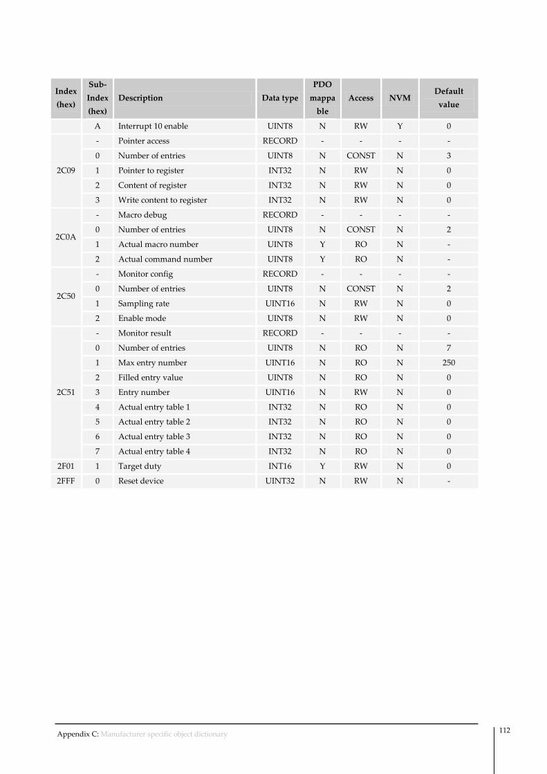
Appendix C: Manufacturer specific object dictionary 112
Index
(hex)
Sub-
Index
(hex)
Description Data type
PDO
mappa
ble
Access NVM Default
value
A Interrupt 10 enable UINT8 N RW Y 0
2C09
- Pointer access RECORD - - - -
0 Number of entries UINT8 N CONST N 3
1 Pointer to register INT32 N RW N 0
2 Content of register INT32 N RW N 0
3 Write content to register INT32 N RW N 0
2C0A
- Macro debug RECORD - - - -
0 Number of entries UINT8 N CONST N 2
1 Actual macro number UINT8 Y RO N -
2 Actual command number UINT8 Y RO N -
2C50
- Monitor config RECORD - - - -
0 Number of entries UINT8 N CONST N 2
1 Sampling rate UINT16 N RW N 0
2 Enable mode UINT8 N RW N 0
2C51
- Monitor result RECORD - - - -
0 Number of entries UINT8 N RO N 7
1 Max entry number UINT16 N RO N 250
2 Filled entry value UINT8 N RO N 0
3 Entry number UINT16 N RW N 0
4 Actual entry table 1 INT32 N RO N 0
5 Actual entry table 2 INT32 N RO N 0
6 Actual entry table 3 INT32 N RO N 0
7 Actual entry table 4 INT32 N RO N 0
2F01 1 Target duty INT16 Y RW N 0
2FFF 0 Reset device UINT32 N RW N -

References 113
References
CiA DS-301 Application layer and communication profile
CiA DR-303 Additional specification
CiA DS-305 Layer setting services (LSS) and protocols
CiA DS-306 Electronic data sheet specification for CANopen
CiA DSP-402 Drives and motion control device profile
Document versions
1.0 First release version.
1.1 Update to FW version 0.92.
Fixed some linked reference errors.
1.2
Fixed register number of “Current direct/Quadrature” register.
Added comment in register 0x6505.
Changed Data type of “Phasing tolerance”, “Phasing time” “Phasing current” register.
Fixed encoder bits of representation of register “Dedicated digital input”.
Fixed description of Sequence commands registers 0x2C02 subindex 0xA and 0xB.
1.3
Added Document versions table.
Update for FW version 2.0.
Modified analog input resolution from 10 bits to 12 bits.
Added unpush macro feature (register 0x2C04 subindex 0x07).
Added Macro protected access feature (register 0x2C05 subindex 0x04).
Added Analog output automatic (register 0x2A08).
Change scaling of Torque/Flux control loop from 11 to 8 bits.
Added spring compensation mode.
Updated analog command source offset.
Added sign extension comment on W2.


![Group #2 / Embedded Motion Control [5HC99] Embedded Visual Control 1 Group #5 / Embedded Visual Control Self-Balancing Robot Navigation Paul Padila Vivian](https://img.pdfslide.us/doc/110x75/56649e685503460f94b6469a/group-2-embedded-motion-control-5hc99-embedded-visual-control-1-group.jpg)