Embed Size (px)
Citation preview

Energy Response Pty Ltd Level 1, 250 Queen Street, Melbourne VIC 3000 (ABN 49 104 710 278)
Visit our website at www.energyresponse.com
Document No. EMB-DLF-GLR-01
Title: DISTRIBUTION LOSS FACTOR CALCULATION
METHODOLOGY FOR AMCOR GAWLER GLASS
FACTORY
Document Status
Revision Prepared by Authorised by Issue Date
External, Internal or Limited Use
00C TiHaur Tan Paul Troughton 17/02/09
External
(Confidential Information Withheld)

Distribution Loss Factor Calculation Methodology - EMB-DLF-GLR-01 Revision 00C
Energy Response Holding Pty Ltd ABN 47 108 827 596, 2009. Page 2 of 11 File: Distribution Loss Factor Calculation Methodology 00C - Public.doc
TABLE OF CONTENTS
1 INTRODUCTION.................................................................................................. 3
1.1 AMCOR GAWLER GLASS FACTORY ..................................................................... 3
1.2 AMCOR GAWLER EXEMPT NETWORK SERVICE .................................................... 3
1.3 GENERATOR OPERATING STATES ...................................................................... 4
2 AMCOR GAWLER GENERATOR DLF CALCULATION .................................... 5
2.1 APPROACH ....................................................................................................... 5
2.2 IDENTIFICATION OF DISTRIBUTION LOSSES .......................................................... 6
2.2.1 11kV Incomer Network (Stage 1 & Stage 2) .....................................................................7
2.2.2 Essential Line No. 1 & No. 2 (Stage 1 & Stage 2).............................................................7
3 MODELLING OF DISTRIBUTION LOSSES........................................................ 8
4 CALCULATION OF DISTRIBUTION LOSS FACTORS...................................... 8
4.1 LOSSES WITHOUT GENERATORS RUNNING .......................................................... 8
4.1.1 For Stage 1........................................................................................................................8
4.1.2 For Stage 2........................................................................................................................8
4.2 LOSSES WITH GENERATORS RUNNING................................................................ 8
4.2.1 For Stage 1........................................................................................................................8
4.2.2 For Stage 2........................................................................................................................8
4.3 MLF & DLF CALCULATION ................................................................................ 8
REFERENCES........................................................................................................... 9
VERSION MANAGEMENT ........................................................................................ 9
Distribution Loss Factor Calculation Methodology - EMB-DLF-GLR-01 Revision 00C
Energy Response Holding Pty Ltd ABN 47 108 827 596, 2009. Page 3 of 11 File: Distribution Loss Factor Calculation Methodology 00C - Public.doc
Distribution Loss Factor Calculation Methodology
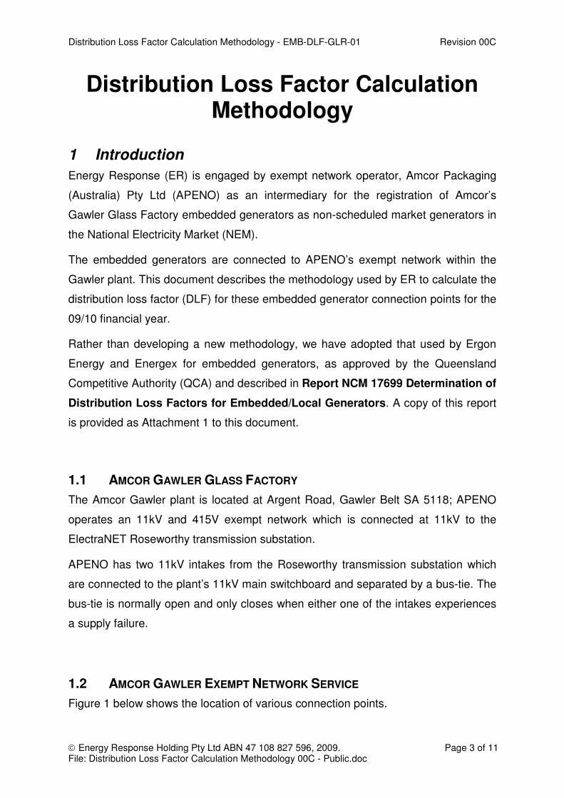
1 Introduction
Energy Response (ER) is engaged by exempt network operator, Amcor Packaging
(Australia) Pty Ltd (APENO) as an intermediary for the registration of Amcor’s
Gawler Glass Factory embedded generators as non-scheduled market generators in
the National Electricity Market (NEM).
The embedded generators are connected to APENO’s exempt network within the
Gawler plant. This document describes the methodology used by ER to calculate the
distribution loss factor (DLF) for these embedded generator connection points for the
09/10 financial year.
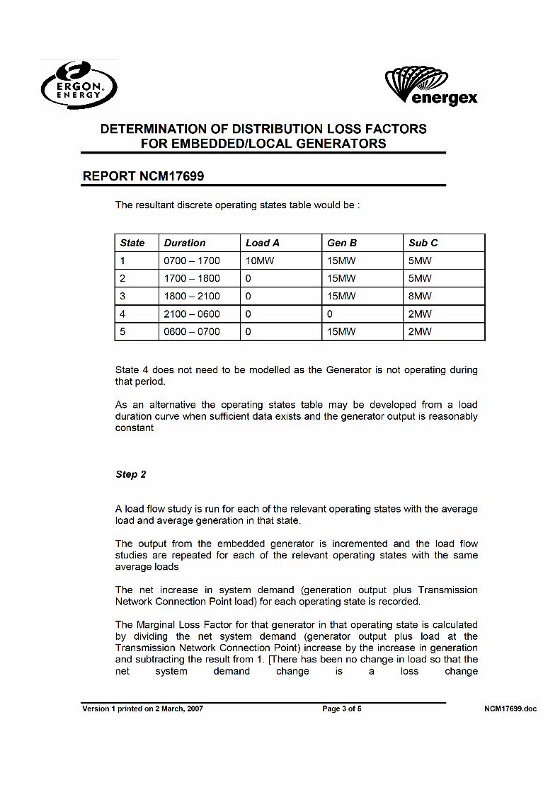
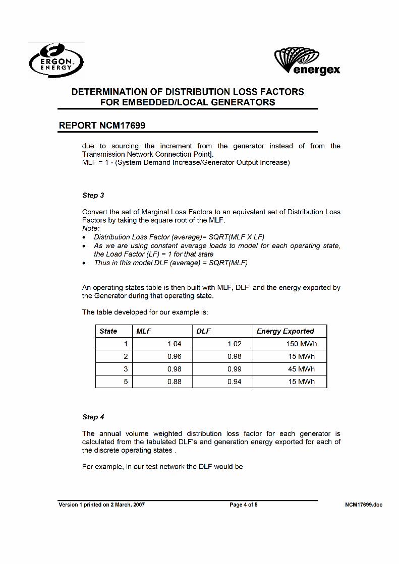
Rather than developing a new methodology, we have adopted that used by Ergon
Energy and Energex for embedded generators, as approved by the Queensland
Competitive Authority (QCA) and described in Report NCM 17699 Determination of
Distribution Loss Factors for Embedded/Local Generators. A copy of this report
is provided as Attachment 1 to this document.
1.1 AMCOR GAWLER GLASS FACTORY
The Amcor Gawler plant is located at Argent Road, Gawler Belt SA 5118; APENO
operates an 11kV and 415V exempt network which is connected at 11kV to the
ElectraNET Roseworthy transmission substation.
APENO has two 11kV intakes from the Roseworthy transmission substation which
are connected to the plant’s 11kV main switchboard and separated by a bus-tie. The
bus-tie is normally open and only closes when either one of the intakes experiences
a supply failure.
1.2 AMCOR GAWLER EXEMPT NETWORK SERVICE
Figure 1 below shows the location of various connection points.

Distribution Loss Factor Calculation Methodology - EMB-DLF-GLR-01 Revision 00C
Energy Response Holding Pty Ltd ABN 47 108 827 596, 2009. Page 4 of 11 File: Distribution Loss Factor Calculation Methodology 00C - Public.doc
Figure 1 - Simplified representation of the APENO exempt network
1.3 GENERATOR OPERATING STATES
The embedded generators on APENO’s exempt network will not be running
continuously. They will be run as a peaking plant, in response to high spot prices in
the South Australian market. Extrapolating from historical market data, we expect
this to be 20-80 hours per year, and would be surprised if it exceeded 150 hours.
The generators may also be run at ElectraNET’s request to relieve network
constraints, or as part of a NEMMCO reserve programme, or under NEMMCO’s
direction. They will also continue to be run for test and maintenance purposes, and
as required for plant operations.

Distribution Loss Factor Calculation Methodology - EMB-DLF-GLR-01 Revision 00C
Energy Response Holding Pty Ltd ABN 47 108 827 596, 2009. Page 5 of 11 File: Distribution Loss Factor Calculation Methodology 00C - Public.doc
Amcor Gawler Glass Factory has a fairly consistent energy consumption profile 24
hours a day, 7 days a week, and 365 days a year. This is confirmed by the historical
meter data obtained from the ElectraNET-APENO connection point, as well as from
the plant’s Energy Management System records. An energy consumption profile of
the plant for the period 17 Dec 2007 till 17 Dec 2008 is provided as Attachment 2 to
this document.
The embedded generators are connected to the Essential Switchboards. When
instructed to run, Stage 1 generator typically supplies 600kW out of the typical
700kW loads connected to Stage 1 Essential Switchboard; whereas Stage 2
generator typically supplies 700kW out of the typical 800kW loads connected to
Stage 2 Essential Switchboard. (100kW load is still supplied by the grid as a buffer to
prevent reverse power from the embedded generator to the grid in the event of
sudden load drop from the Essential Switchboards.)
The Marginal Loss Factor for the embedded generator connection points is
calculated based on the net reduction in distribution losses within the APENO
exempt network when the generators run.
2 Amcor Gawler Generator DLF Calculation
The site specific DLF for the Amcor Gawler embedded generators will be calculated
using a Marginal Loss Factor (MLF) approach as described in Report NCM 17699
Determination of Distribution Loss Factors for Embedded/Local Generators.
2.1 APPROACH
The DLF is a static loss factor which is to apply to the embedded generator exempt
network connection point for the full financial year. The steps undertaken to calculate
the DLF are summarized as follows:-
1. Request Amcor Gawler Glass Factory consumption data for the past year – from
Amcor Packaging (Australia) Pty Ltd.
2. Request plant equipment data and specifications for the APENO exempt network
– from Amcor Packaging (Australia) Pty Ltd.

Distribution Loss Factor Calculation Methodology - EMB-DLF-GLR-01 Revision 00C
Energy Response Holding Pty Ltd ABN 47 108 827 596, 2009. Page 6 of 11 File: Distribution Loss Factor Calculation Methodology 00C - Public.doc
3. Develop an equivalent network model for the APENO exempt network by
incorporating all relevant equipment data and specifications.
4. Calculate the estimated distribution losses due to APENO exempt network’s
impedance.
5. Calculate the MLF and DLF in accordance with the methods described in Report
NCM 17699 Determination of Distribution Loss Factors for
Embedded/Local Generators.
Notes:
• The losses in the APENO exempt network have been calculated using the
impedance values of the distribution equipment and cables.
• The relevant distribution losses are those between the 11kV APENO connection
point at Roseworthy and the embedded generator connection points.
• The plant has a fairly consistent load profile with minimal changes in consumption
trends, and there are no significant changes to the plant’s loads expected in the
foreseeable future. Therefore it is assumed that the historical consumption data
from the past year is a sufficiently accurate estimate for the forecast DLF for
09/10 financial year.
2.2 IDENTIFICATION OF DISTRIBUTION LOSSES
ER has segmented APENO’s exempt network into three levels between the
ElectraNET-APENO connection point and the embedded generators for both Stage 1
& Stage 2:-
o Stage 1
- 11kV Incomer Network
- Essential Line No. 1 - 11kV Feeder, 11kV/415V Transformers, 415V Busduct & 415V Incomer
- Essential Line No. 2 - 11kV Feeder, 11kV/415V Transformers, 415V Busduct & 415V Incomer
o Stage 2
- 11kV Incomer Network
- Essential Line No. 1 - 11kV Feeder, 11kV/415V Transformers, 415V Busduct & 415V Incomer Network No. 1

Distribution Loss Factor Calculation Methodology - EMB-DLF-GLR-01 Revision 00C
Energy Response Holding Pty Ltd ABN 47 108 827 596, 2009. Page 7 of 11 File: Distribution Loss Factor Calculation Methodology 00C - Public.doc
- Essential Line No. 2 - 11kV Feeder, 11kV/415V Transformers, 415V Busduct & 415V Incomer Network No. 2
The distribution losses for each of these were derived in turn:-
2.2.1 11kV Incomer Network (Stage 1 & Stage 2)
The main contributions to losses on the 11kV incomer network have been identified
as follows:-
o Copper Losses across the 11kV cables from the Roseworthy substation to the
11kV switchboard
o Copper Losses across the 11kV Main Switchboard Incomer Circuit Breakers
It has been assumed that negligible losses are developed across the 11kV main
switchboard busbars; therefore those losses are ignored.
2.2.2 Essential Line No. 1 & No. 2 (Stage 1 & Stage 2) - 11kV Feeder, 11kV/415V Transformers, 415V Busduct & 415V Incomer
The main contributions to losses on the Essential Lines No. 1 & No. 2 have been
identified as follows:-
o Copper Losses across the 11kV Main Switchboard Feeder Circuit Breakers
o Copper Losses across the 11kV cables from the 11kV switchboards to the
11kV/415V transformers
o Copper Losses across the transformer winding
o Iron Losses in the transformer core
o Copper Losses across the 415V Busduct from the transformer to the 415V
Essential Switchboard
o Copper Losses across the 415V Essential Switchboard Incomer Circuit
Breakers
It has been assumed that negligible losses are developed across the 415V essential
switchboard busbars; therefore those losses are not considered.
Attachment 3 lists the technical details obtained from Amcor Packaging (Australia)
Pty Ltd.

Distribution Loss Factor Calculation Methodology - EMB-DLF-GLR-01 Revision 00C
Energy Response Holding Pty Ltd ABN 47 108 827 596, 2009. Page 8 of 11 File: Distribution Loss Factor Calculation Methodology 00C - Public.doc
3 Modelling of Distribution Losses
Based on the sources of losses identified in (2.2) and on data obtained in (2.1), we
can calculate the parameters for the equivalent network model of the APENO
exempt network as detailed in Attachment 2 and Attachment 3. Subsequently, the
equivalent network as referred to 11kV can be obtained as follows:-
(NOTE: Cable, busduct & transformer inductances are not included in the equivalent
network because we are only interested in the active power losses of the APENO
exempt network.)
[Confidential Network Information Withheld]
4 Calculation of Distribution Loss Factors
We can arrive at the distribution losses without and with generators running for both
Stage 1 and Stage 2 as follows:-
[Confidential Network Information Withheld]
4.1 MLF & DLF CALCULATION
In accordance with the methods described in Report NCM 17699 Determination of
Distribution Loss Factors for Embedded/Local Generators, we can obtain the
MLF for the embedded generator connection points as follows:-
MLF = 1.0050
[Confidential Network Information Withheld]
Converting the MLF to DLF:-
DLF = √(1.0050)
= 1.002

Distribution Loss Factor Calculation Methodology - EMB-DLF-GLR-01 Revision 00C
Energy Response Holding Pty Ltd ABN 47 108 827 596, 2009. Page 9 of 11 File: Distribution Loss Factor Calculation Methodology 00C - Public.doc
References
1 Oaky Creek Distribution Loss Factor Calculation Methodology dated 25/02/2008 by Hill Michael
2 Moranbah North Power Station Distribution Loss Factor Calculation Methodology dated 25/03/2008 by Hill Michael
3 Capcoal Distribution Loss Factor Calculation Methodology dated 25/02/2008 by Hill Michael
4 Determination of Distribution Loss Factors for Embedded / Local Generators dated 02/03/2007 by Ergon Energy & Energex
NCM17699
Version Management Version Date Reason For Change Author Approved
00A 14/01/2009 First draft TiHaur Tan
00B 20/01/2009 For Review TiHaur Tan Paul Troughton
00C 17/02/2009 Amended as per Comments TiHaur Tan Paul Troughton

Distribution Loss Factor Calculation Methodology - EMB-DLF-GLR-01 Revision 00C
Energy Response Holding Pty Ltd ABN 47 108 827 596, 2009. Page 10 of 11 File: Distribution Loss Factor Calculation Methodology 00C - Public.doc
ATTACHMENT 1:
REPORT NCM 17699
DETERMINATION OF DISTRIBUTION LOSS FACTORS FOR EMBEDDED/LOCAL GENERATORS


Distribution Loss Factor Calculation Methodology - EMB-DLF-GLR-01 Revision 00C
Energy Response Holding Pty Ltd ABN 47 108 827 596, 2009. Page 11 of 11 File: Distribution Loss Factor Calculation Methodology 00C - Public.doc
ATTACHMENT 2: Summary of Amcor Gawler Plant Consumption Details for the period 17/12/2008 till 17/12/2008
[Confidential Network Information Withheld]
ATTACHMENT 3: Amcor Gawler Plant Technical Details
[Confidential Network Information Withheld]


![DLF - BROFER DIF DIAGRAMMA SCELTA RAPIDA / QUICK SELECTION DIAGRAM DLF 8-1000 DLF 7-1000 DLF 6-1000 DLF 5-1000 DLF 4-1000 DLF 3-1000 DLF 2-1000 DLF 1-1000 0 500 1000 1500 2000 Q [m3/h]](https://img.pdfslide.us/doc/110x75/5b06b1047f8b9ad5548d39b5/dlf-dif-diagramma-scelta-rapida-quick-selection-diagram-dlf-8-1000-dlf-7-1000.jpg)