Embed Size (px)
Citation preview
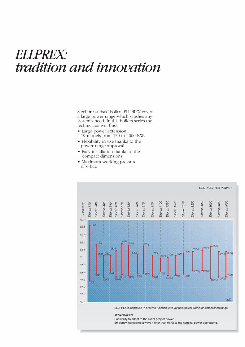
ELLPREX:tradition and innovation
Steel pressurised boilers ELLPREX covera large power range which satisfies anysystem’s need. In this boilers series thetechnicians will find:• Large power extension:
19 models from 130 to 4000 KW.• Flexibility in use thanks to the
power range approval.• Easy installation thanks to the
compact dimensions.• Maximum working pressure
of 6 bar.
CERTIFICATED POWER
model
Effi
cien
cy
ELLPREX is approved in order to function with variable power within an established range.
ADVANTAGES:Possibility to adapt to the exact project powerEfficiency increasing (always higher than 91%) to the nominal power decreasing.
(170)
Ellp
rex
170
Ellp
rex
240
Ellp
rex
290
Ellp
rex
420
(580)
Ellp
rex
760
(870)
Ellp
rex
870
(970)
Ellp
rex
970
Ellp
rex
1100
Ellp
rex
1320
(1200)
Ellp
rex
1570
Ellp
rex
2200
Ellp
rex
2650
Ellp
rex
3000
Ellp
rex
3500
(1400)
Ellp
rex
1850
Ellp
rex
340
Ellp
rex
630
Ellp
rex
510
(510)
(860)
91,6
91,8
92
92,2
92,4
91,4
91,2
92,6
92,8
93,0
91,0
90,8
(130)
(180)
(240)
(290) (420 )
(340)
(220) (225)
(315)
(385)(480) (660)
(760)(630)
(750)
(1100)
(1320) (1570)
(1700) (2000)(2300)
(3000)
(1000)
(1850)
(2650)(2200)
(kW)
Ellp
rex
4000
(4000)
(3200)(2700)
(3500)
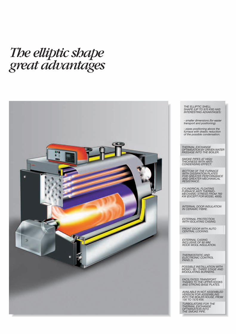
The elliptic shapegreat advantages
THE ELLIPTIC SHELLSHAPE (UP TO 970 KW) HASINTERESTING ADVANTAGES:
- smaller dimensions (for easiertransport and positioning).
- pipes positioning above thefurnace with drastic reductionof the possible condensation.
SMOKE PIPES AT HIGHTHICKNESS WITH ANTI-CONDENSING EFFECT.
BOTTOM OF THE FURNACEWITH DISSIPATION PLATESFOR GREATER PERFORMANCEAND GREATER MECHANICALRESISTANCE.
THERMAL EXCHANGEOPTIMISATION BY DRIVEN WATERPASSAGE INTO THE BOILER.
CYLINDRICAL FLOATINGFURNACE ANTI THERMO-MECHANIC STRESS FROM 760KW (EXCEPT FOR MODEL 4000).
INTERNAL DOOR INSULATIONIN CERAMIC FIBRE.
EXTERNAL PROTECTIONWITH ISOLATING CASING.
FRONT DOOR WITH AUTOCENTRAL LOCKING.
EXTERNAL CASINGINCLUSIVE OF 80 MMROCK WOOL INSULATION.
THERMOSTATIC ANDELECTRONIC CONTROLPANELS.
POSSIBLE INSTALLATION WITHMONO / BI / THREE STAGE ANDMODULATING BURNERS.
FACILITATED TRANSPORTTHANKS TO THE UPPER HOOKSAND STRONG BASE PLATES.
AVAILABLE IN NOT ASSEMBLEDVERSION FOR ASSEMBLINGINTO THE BOILER HOUSE, FROM130 TO 1570 KW.
TURBOLATORS FOR THETHERMAL EXCHANGEOPTIMISATION INTOTHE SMOKE PIPE.
The technique...
UNIFORM TEMPERATUREDISTRIBUTION
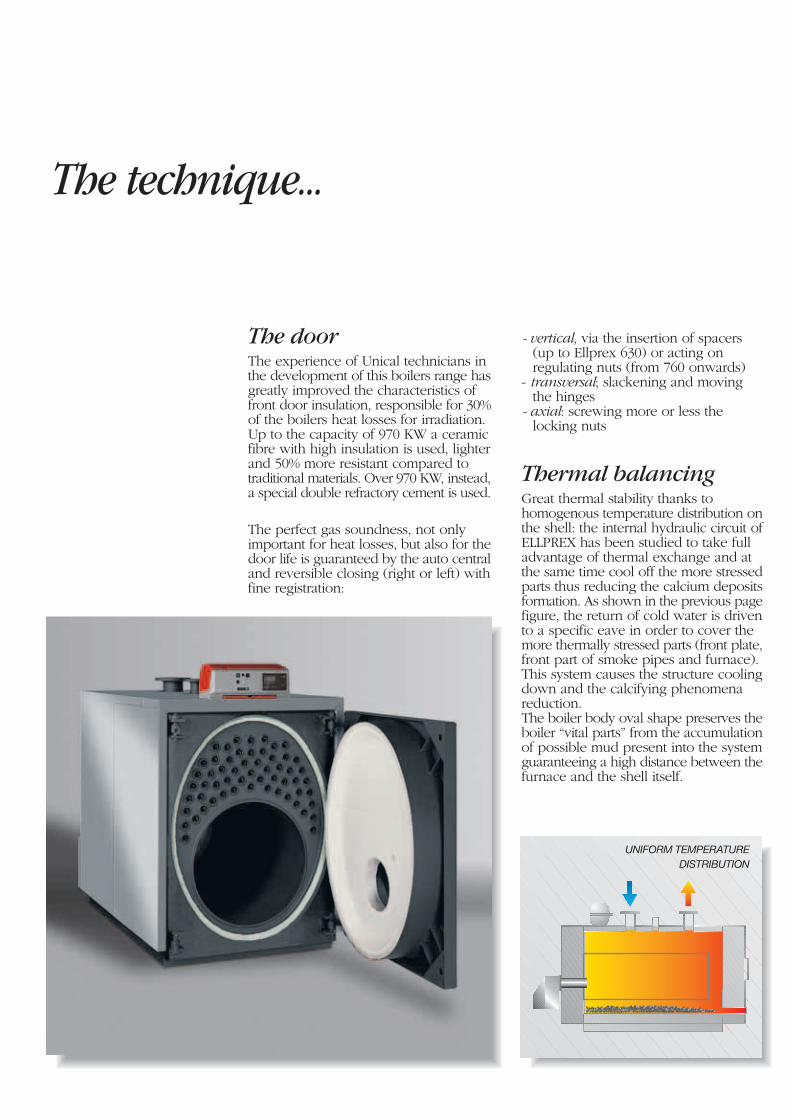
The doorThe experience of Unical technicians inthe development of this boilers range hasgreatly improved the characteristics offront door insulation, responsible for 30%of the boilers heat losses for irradiation.Up to the capacity of 970 KW a ceramicfibre with high insulation is used, lighterand 50% more resistant compared totraditional materials. Over 970 KW, instead,a special double refractory cement is used.
The perfect gas soundness, not onlyimportant for heat losses, but also for thedoor life is guaranteed by the auto centraland reversible closing (right or left) withfine registration:
- vertical, via the insertion of spacers(up to Ellprex 630) or acting onregulating nuts (from 760 onwards)
- transversal; slackening and movingthe hinges
- axial: screwing more or less thelocking nuts
Thermal balancingGreat thermal stability thanks tohomogenous temperature distribution onthe shell: the internal hydraulic circuit ofELLPREX has been studied to take fulladvantage of thermal exchange and atthe same time cool off the more stressedparts thus reducing the calcium depositsformation. As shown in the previous pagefigure, the return of cold water is drivento a specific eave in order to cover themore thermally stressed parts (front plate,front part of smoke pipes and furnace).This system causes the structure coolingdown and the calcifying phenomenareduction.The boiler body oval shape preserves theboiler “vital parts” from the accumulationof possible mud present into the systemguaranteeing a high distance between thefurnace and the shell itself.
…and the boiler art
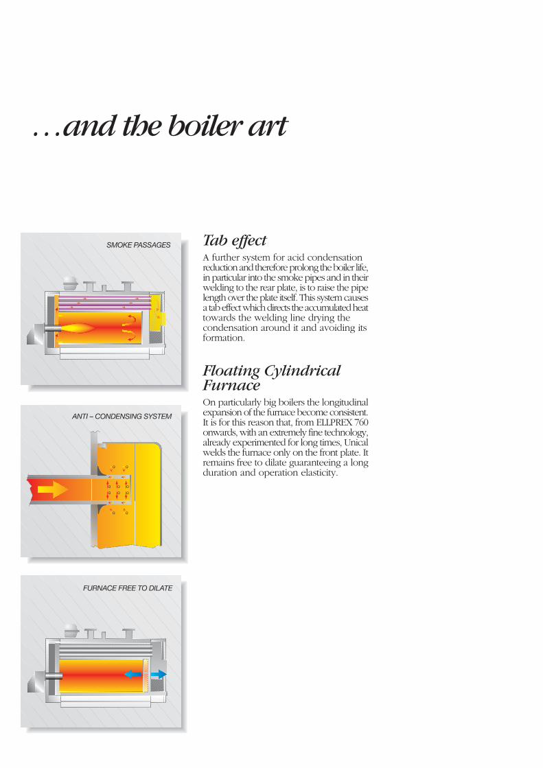
SMOKE PASSAGES
FURNACE FREE TO DILATE
Q Q Q
Q Q Q
Q Q
Q Q
ANTI – CONDENSING SYSTEM
Tab effectA further system for acid condensationreduction and therefore prolong the boiler life,in particular into the smoke pipes and in theirwelding to the rear plate, is to raise the pipelength over the plate itself. This system causesa tab effect which directs the accumulated heattowards the welding line drying thecondensation around it and avoiding itsformation.
Floating CylindricalFurnaceOn particularly big boilers the longitudinalexpansion of the furnace become consistent.It is for this reason that, from ELLPREX 760onwards, with an extremely fine technology,already experimented for long times, Unicalwelds the furnace only on the front plate. Itremains free to dilate guaranteeing a longduration and operation elasticity.
The control panel
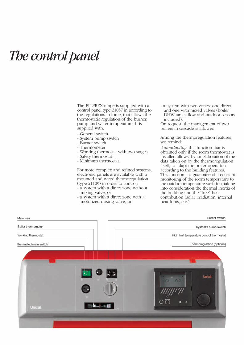
The ELLPREX range is supplied with acontrol panel type 21057 in according tothe regulations in force, that allows thethermostatic regulation of the burner,pump and water temperature. It issupplied with:- General switch- System pump switch- Burner switch- Thermometer- Working thermostat with two stages- Safety thermostat- Minimum thermostat.
For more complex and refined systems,electronic panels are available with amounted and wired thermoregulation(type 21109) in order to control:- a system with a direct zone without
mixing valve, or- a system with a direct zone with a
motorized mixing valve, or
- a system with two zones: one directand one with mixed valves (boiler,DHW tanks, flow and outdoor sensorsincluded).
On request, the management of twoboilers in cascade is allowed.
Among the thermoregulation featureswe remind:Autoadapting: this function that isobtained only if the room thermostat isinstalled allows, by an elaboration of thedata taken on by the thermoregulationitself, to adapt the boiler operationaccording to the building features.This function is a guarantee of a constantmonitoring of the room temperature tothe outdoor temperature variation, takinginto consideration the thermal inertia ofthe building and the “free” heatcontribution (solar irradiation, internalheat fonts, etc.)
Boiler thermometer
Working thermostat.
Illuminated main switch
Main fuse Burner switch
System’s pump switch
High limit temperature control thermostat
Thermoregulation (optional)
For a simple and economicalheat management
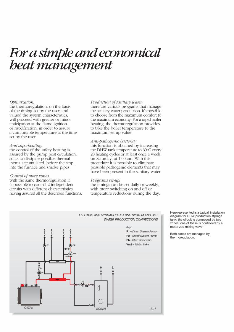
Here represented is a typical installationdiagram for DHW production stpragetank; the circuit is composed by twozones: one of these is controlled by amotorized mixing valve.
Both zones are managed bythermoregulation.
Optimization:the thermoregulation, on the basisof the timing set by the user, andvalued the system characteristics,will proceed with greater or minoranticipation at the flame ignitionor modification, in order to assurea comfortable temperature at the timeset by the user.
Anti superheating:the control of the safety heating isassured by the pump post circulation,so as to dissipate possible thermalinertia accumulated, before the stop,into the furnace and smoke pipes.
Control of more zones:with the same thermoregulation itis possible to control 2 independentcircuits with different characteristics,having assured all the described functions.
BOILERCAZAN
ELECTRIC AND HYDRAULIC HEATING SYSTEM AND HOTWATER PRODUCTION CONNECTIONS
fig. 1
Production of sanitary water:there are various programs that managethe sanitary water production. It’s possibleto choose from the maximum comfort tothe maximum economy. For a rapid boilerheating, the thermoregulation providesto take the boiler temperature to themaximum set up value.
Anti-pathogenic bacteria:this function is obtained by increasingthe DHW tank temperature to 60°C every20 heating cycles or at least once a week,on Saturday, at 1.00 am. With thisprocedure it is possible to eliminatepossible pathogenic elements that mayhave been present in the sanitary water.
Programs set-up:the timings can be set daily or weekly,with more switching on and off ortemperature reductions during the day.
Key:
P1 – Direct System Pump
P2 – Mixed System Pump
Pb.- Dhw Tank Pump
Vm2 – Mixing Valve
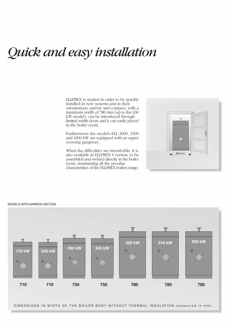
Quick and easy installation
ELLPREX is studied in order to be quicklyinstalled in new systems and in theirsubstitutions: narrow and compact, with amaximum width of 780 mm (up to the 630kW model), can be introduced throughlimited width doors and it can easily placedin the boiler room.
Furthermore the models ELL 3000, 3500and 4000 kW are equipped with an uppercrossing gangway.
When the difficulties are irresolvable, it isalso available in ELLPREX S version, to beassembled and welded directly in the boilerroom, maintaining all the peculiarcharacteristics of the ELLPREX boilers range.
MODELS WITH NARROW SECTION
710 750 750 780 780 780710
630 kW
290 kW 340 kW420 kW 510 kW
170 kW 240 kW
D I M E N S I O N S I N W I D T H O F T H E B O I L E R B O D Y W I T H O U T T H E R M A L I N S U L AT I O N ( m e a s u r e d i n m m )
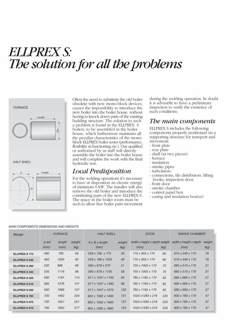
ELLPREX S:The solution for all the problems
MAIN COMPONENTS DIMENSIONS AND WEIGHTS
Often the need to substitute the old boilerobsolete with new mono-block devices,causes the impossibility to introduce thenew boiler into the boiler house, withouthaving to knock down parts of the existingbuilding structure. The solution to sucha problem is found in the ELLPREX Sboilers, to be assembled in the boilerhouse, which furthermore maintains allthe peculiar characteristics of the mono-block ELLPREX boiler series (performance,flexibility in functioning etc.). Our qualifiedor authorised by us staff will directlyassemble the boiler into the boiler houseand will complete the work with the finalhydraulic test.
Local PredispositionFor the welding operations it’s necessaryto have at disposition an electric energyof minimum 6 kW. The installer will alsoremove the old boiler and introduce theconstituting parts of the new ELLPREX S.The space in the boiler room must besuch to allow free boiler parts movement
Ø e
FURNACE
Length
HALF SHELL
A
B
Length
Model FURNACE
ø ext. length weight
480
480
530
530
580
580
580
700
700
700
ELLPREX S 170
ELLPREX S 240
ELLPREX S 290
ELLPREX S 340
ELLPREX S 420
ELLPREX S 510
ELLPREX S 630
ELLPREX S 760
ELLPREX S 870
ELLPREX S 970
790
1050
986
1116
1181
1376
1686
1462
1657
1852
64
82
88
98
114
131
157
224
251
277
HALF SHELL
558 x 788 x 775
558 x 788 x 1035
590 x 879 x 970
590 x 879 x 1100
617 x 1047 x 1165
30
40
51
58
84
98
120
121
137
153
DOOR
710 x 905 x 170
710 x 905 x 170
750 x 1005 x 170
750 x 1005 x 170
780 x 1165 x 170
780 x 1165 x 170
780 x 1165 x 170
1024 x1280 x 216
1024 x1280 x 216
1024 x1280 x 216
60
60
70
70
82
82
82
225
225
225
SMOKE CHAMBER
width x height x depth weight
610 x 440 x 170
610 x 440 x 170
660 x 510 x 170
660 x 510 x 170
690 x 660 x 170
690 x 660 x 170
690 x 660 x 170
900 x 790 x 170
900 x 790 x 170
900 x 790 x 170
18
18
21
21
27
27
27
47
47
47
(mm) (mm) (kg) (mm) (kg) (mm) (kg) (mm) (kg)
A x B x length weight
617 x 1047 x 1360
617 x 1047 x 1670
802 x 1082 x 1490
802 x 1082 x 1685
802 x 1082 x 1880
during the welding operation. In doubtit is advisable to have a preliminaryinspection to verify the existence ofsuch conditions.
The main componentsELLPREX S includes the followingcomponents properly positioned on asupporting structure for transport andmovement:- front plate- rear plate- shell (in two pieces)- furnace- insulation- smoke pipes- turbolators- connections, tile distributors, lifting
hooks, inspection door,- front door- smoke chamber- control panel box- casing and insulation box(es)
width x height x depth weight
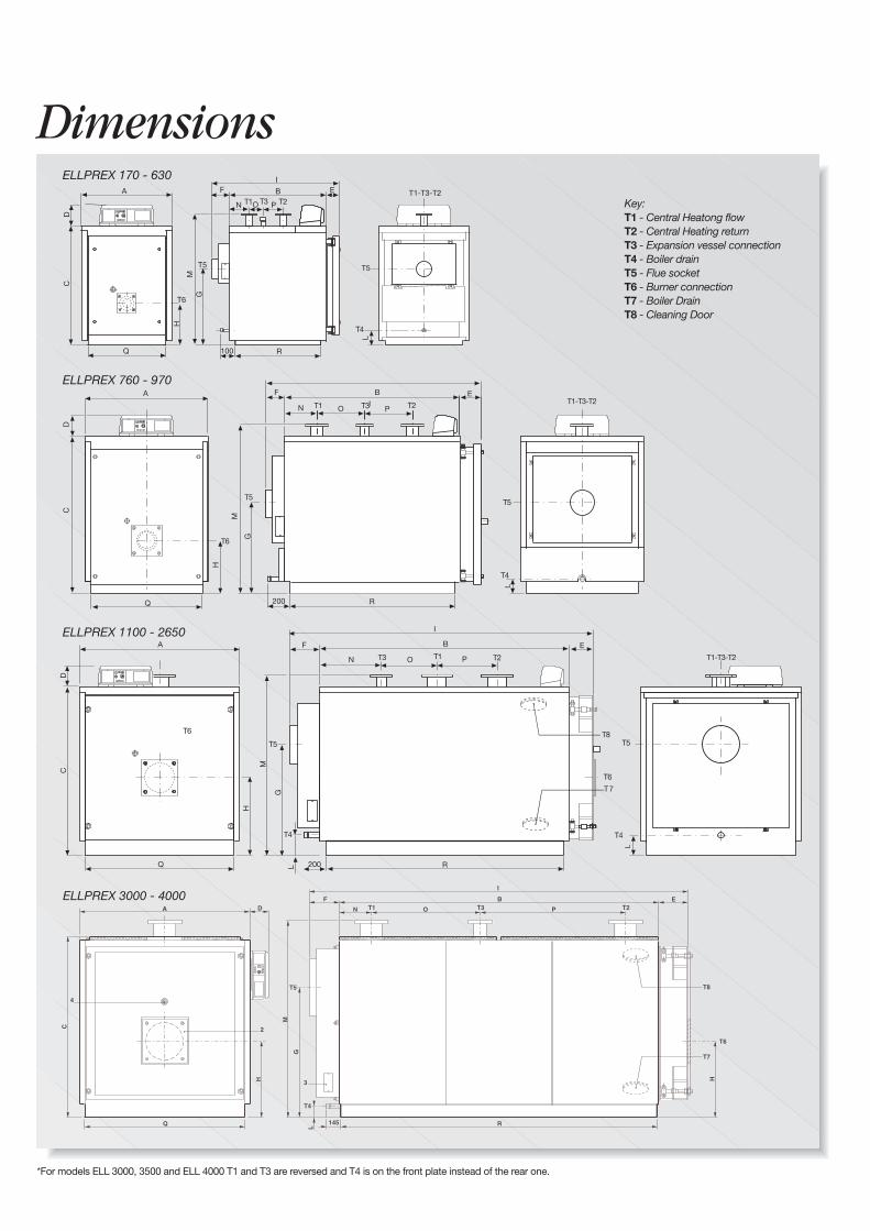
DimensionsELLPREX 170 - 630
ELLPREX 760 - 970
ELLPREX 1100 - 2650
*For models ELL 3000, 3500 and ELL 4000 T1 and T3 are reversed and T4 is on the front plate instead of the rear one.
A
H
G
CD
T6
T5
T1BF
N
E
T4
O P
T5
T1-T3-T2M
Q R
T2T3
100
L
I
H
T6
A
DC
Q
G
T5
T1
BF
N
E
O
M
T3
R
T4
T5
T1-T3-T2T2P
G
T5
T3
BF
N
E
T6
O
M
R
A
Q
T4
T5
DC
T1-T3-T2
H
T6
T2T1 P
200
200
L
L
I
I
L
T4
ELLPREX 3000 - 4000
T8
T7
Key:T1 - Central Heatong flowT2 - Central Heating returnT3 - Expansion vessel connectionT4 - Boiler drainT5 - Flue socketT6 - Burner connectionT7 - Boiler DrainT8 - Cleaning Door
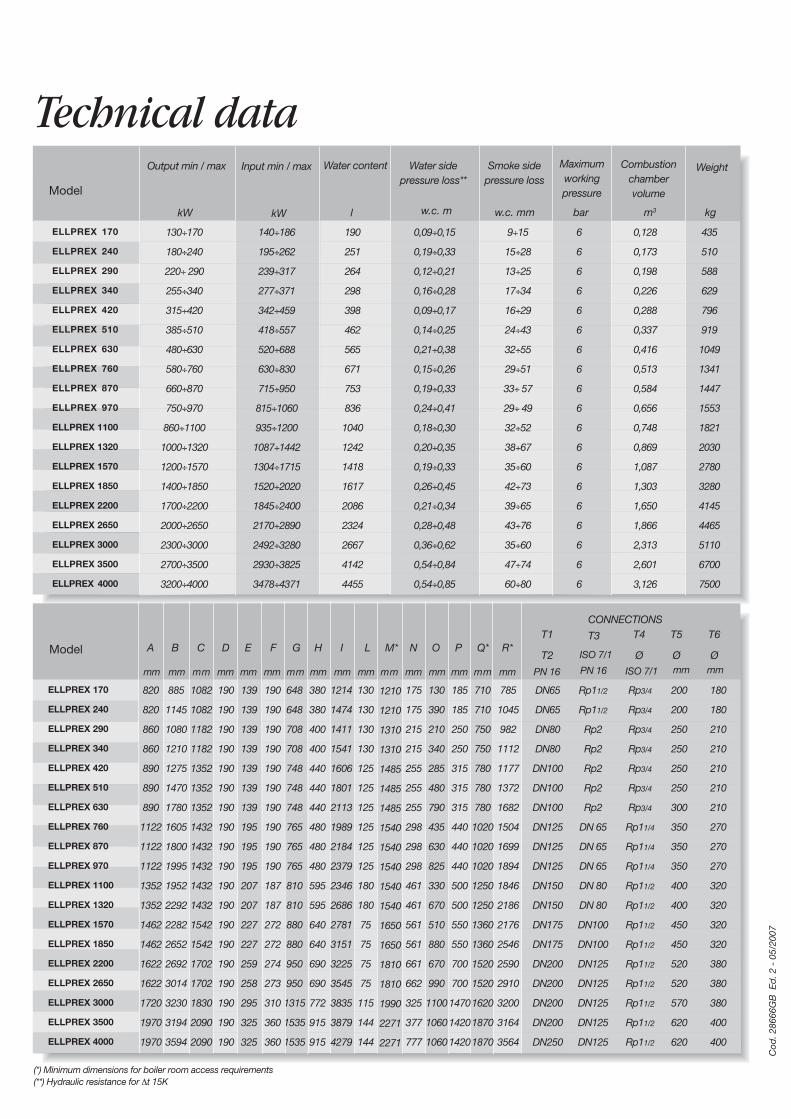
(*) Minimum dimensions for boiler room access requirements(**) Hydraulic resistance for ∆t 15K
Cod
. 286
66G
B E
d. 2
- 0
5/20
07
Technical data
Model
kW
Water content
l
Water sidepressure loss**
w.c. m
Combustionchambervolume
m3
Weight
kg
Smoke sidepressure loss
w.c. mm
Maximumworkingpressure
barkW
Output min / max Input min / max
ELLPREX 170
ELLPREX 240
ELLPREX 290
ELLPREX 340
ELLPREX 420
ELLPREX 510
ELLPREX 630
ELLPREX 760
ELLPREX 870
ELLPREX 970
ELLPREX 1100
ELLPREX 1320
ELLPREX 1570
ELLPREX 1850
ELLPREX 2200
ELLPREX 2650
ELLPREX 3000
ELLPREX 3500
ELLPREX 4000
130÷170
180÷240
220÷ 290
255÷340
315÷420
385÷510
480÷630
580÷760
660÷870
750÷970
860÷1100
1000÷1320
1200÷1570
1400÷1850
1700÷2200
2000÷2650
2300÷3000
2700÷3500
3200÷4000
190
251
264
298
398
462
565
671
753
836
1040
1242
1418
1617
2086
2324
2667
4142
4455
140÷186
195÷262
239÷317
277÷371
342÷459
418÷557
520÷688
630÷830
715÷950
815÷1060
935÷1200
1087÷1442
1304÷1715
1520÷2020
1845÷2400
2170÷2890
2492÷3280
2930÷3825
3478÷4371
0,09÷0,15
0,19÷0,33
0,12÷0,21
0,16÷0,28
0,09÷0,17
0,14÷0,25
0,21÷0,38
0,15÷0,26
0,19÷0,33
0,24÷0,41
0,18÷0,30
0,20÷0,35
0,19÷0,33
0,26÷0,45
0,21÷0,34
0,28÷0,48
0,36÷0,62
0,54÷0,84
0,54÷0,85
6
6
6
6
6
6
6
6
6
6
6
6
6
6
6
6
6
6
6
9÷15
15÷28
13÷25
17÷34
16÷29
24÷43
32÷55
29÷51
33÷ 57
29÷ 49
32÷52
38÷67
35÷60
42÷73
39÷65
43÷76
35÷60
47÷74
60÷80
0,128
0,173
0,198
0,226
0,288
0,337
0,416
0,513
0,584
0,656
0,748
0,869
1,087
1,303
1,650
1,866
2,313
2,601
3,126
435
510
588
629
796
919
1049
1341
1447
1553
1821
2030
2780
3280
4145
4465
5110
6700
7500
mm
T5
Ø
T6
ØR*
T1
T2
CONNECTIONS
T3 T4
ØQ*PON
mm mm mm mm
LIHGFEDC M*
mm mm mm mm mm mm mm mm mm
Model A B
mm mm mm PN 16 PN 16 ISO 7/1 mm mm
ISO 7/1
820
820
860
860
890
890
890
1122
1122
1122
1352
1352
1462
1462
1622
1622
1720
1970
1970
Rp11/2
Rp11/2
Rp2
Rp2
Rp2
Rp2
Rp2
DN 65
DN 65
DN 65
DN 80
DN 80
DN100
DN100
DN125
DN125
DN125
DN125
DN125
Rp3/4
Rp3/4
Rp3/4
Rp3/4
Rp3/4
Rp3/4
Rp3/4
Rp11/4
Rp11/4
Rp11/4
Rp11/2
Rp11/2
Rp11/2
Rp11/2
Rp11/2
Rp11/2
Rp11/2
Rp11/2
Rp11/2
200
200
250
250
250
250
300
350
350
350
400
400
450
450
520
520
570
620
620
1082
1082
1182
1182
1352
1352
1352
1432
1432
1432
1432
1432
1542
1542
1702
1702
1830
2090
2090
190
190
190
190
190
190
190
190
190
190
190
190
190
190
190
190
190
190
190
139
139
139
139
139
139
139
195
195
195
207
207
227
227
259
258
295
325
325
190
190
190
190
190
190
190
190
190
190
187
187
272
272
274
273
310
360
360
648
648
708
708
748
748
748
765
765
765
810
810
880
880
950
950
1315
1535
1535
885
1145
1080
1210
1275
1470
1780
1605
1800
1995
1952
2292
2282
2652
2692
3014
3230
3194
3594
380
380
400
400
440
440
440
480
480
480
595
595
640
640
690
690
772
915
915
130
130
130
130
125
125
125
125
125
125
180
180
75
75
75
75
115
144
144
175
175
215
215
255
255
255
298
298
298
461
461
561
561
661
662
325
377
777
130
390
210
340
285
480
790
435
630
825
330
670
510
880
670
990
1100
1060
1060
185
185
250
250
315
315
315
440
440
440
500
500
550
550
700
700
1470
1420
1420
1214
1474
1411
1541
1606
1801
2113
1989
2184
2379
2346
2686
2781
3151
3225
3545
3835
3879
4279
710
710
750
750
780
780
780
1020
1020
1020
1250
1250
1360
1360
1520
1520
1620
1870
1870
785
1045
982
1112
1177
1372
1682
1504
1699
1894
1846
2186
2176
2546
2590
2910
3200
3164
3564
DN65
DN65
DN80
DN80
DN100
DN100
DN100
DN125
DN125
DN125
DN150
DN150
DN175
DN175
DN200
DN200
DN200
DN200
DN250
180
180
210
210
210
210
210
270
270
270
320
320
320
320
380
380
380
400
400
ELLPREX 170
ELLPREX 240
ELLPREX 290
ELLPREX 340
ELLPREX 420
ELLPREX 510
ELLPREX 630
ELLPREX 760
ELLPREX 870
ELLPREX 970
ELLPREX 1100
ELLPREX 1320
ELLPREX 1570
ELLPREX 1850
ELLPREX 2200
ELLPREX 2650
ELLPREX 3000
ELLPREX 3500
ELLPREX 4000
1210
1210
1310
1310
1485
1485
1485
1540
1540
1540
1540
1540
1650
1650
1810
1810
1990
2271
2271

Unical AG declines any liability for the inaccuracies that may appear due to errors in transcription or printing. It also reserves the right to introduce thosemodifications to its products that it considers necessary or useful, without compromising the essential characteristics of the said products.