Embed Size (px)
Citation preview
Ellipse 1000/2000Contribution Encoders
User GuideRELEASE 2.14
Revision A
Manual Part No. MAN-ELLIPSE-2.14
© 2012 Harmonic Inc. All rights reserved.
Disclaimer
Harmonic reserves the right to alter the equipment specifications and descriptions in this publication without prior notice. No part ofthis publication shall be deemed to be part of any contract or warranty unless specifically incorporated by reference into suchcontract or warranty. The information contained herein is merely descriptive in nature, and does not constitute a binding offer forsale of the product described herein. Harmonic assumes no responsibility or liability arising from the use of the products describedherein, except as expressly agreed to in writing by Harmonic. The use and purchase of this product do not convey a license underany patent rights, copyrights, trademark rights, or any intellectual property rights of Harmonic. Nothing hereunder constitutes arepresentation or warranty that using any products in the manner described herein will not infringe any patents of third parties.
Trademark Acknowledgments
Harmonic and all Harmonic product names are trademarks of Harmonic Inc. All other trademarks are the property of their respectiveowners.
Compliance and Approval
This equipment has been tested and found to comply with the limits for a Class A digital device, pursuant to Part 15, Subpart B of theFederal Communications Commission (FCC) rules.
These limits are designed to provide reasonable protection against harmful interference when the equipment is operated in acommercial environment.
This equipment generates, uses, and can radiate radio frequency energy. It may cause harmful interference to radio communicationsif it is not installed and used in accordance with the instructions in this manual. Operation of this equipment in a residential area islikely to cause harmful interference. If this occurs, the user will be required to correct the interference at his or her own expense.
This device complies with Part 15 of the FCC rules. Operation is subject to the following two conditions: (1) this device may notcause harmful interference, and (2) this device must accept any interference received, including interference that may causeundesired operation.
Connections between the Harmonic equipment and other equipment must be made in a manner that is consistent with maintainingcompliance with FCC radio frequency emission limits. Modifications to this equipment not expressly approved by Harmonic mayvoid the authority granted to the user by the FCC to operate this equipment.
WEEE/RoHS Compliance Policy
Harmonic Inc. intends to comply fully with the European Union’s Directive 2002/96/EC as amended by Directive 2003/108/EC, onWaste Electrical and Electronic Equipment, also known as “WEEE,” and Directive 2002/95/EC, as amended, on the Restriction ofuse of Hazardous Substances, also known as “RoHS.”
Harmonic will ensure that product which cannot be reused will be recycled in compliance with the WEEE Directive. To that end,users are advised that (1) Harmonic equipment is not to be discarded in household or office garbage, (2) Harmonic Inc. will pay thefreight for shipment of equipment to be disposed of if it is returned to Harmonic, (3) customers should call the normal RMAtelephone numbers to arrange for such shipment, and (4) for additional and updated information on this process customers mayconsult the Harmonic website: http://harmonicinc.com/ah_weee_recycle.cfm.
Harmonic will ensure that its products will be either reused or recycled in compliance with the WEEE Directive. For the latestinformation concerning Harmonic’s WEEE/RoHS Compliance Policy and its Recycling and Take-Back process, please visit our website.

© 2012 Harmonic Inc. All rights reserved.
产品中的有毒有害物质或元素的名称及含量表Names and Contents of the Toxic and Hazardous Substances or Elements in the Products if the Part is Present
该表显示哈雷公司产品中可能含有的有毒有害物质元配件的信息,除了来源于元配件供应商的物料成分资料,亦来自其它相关的机构与资料。哈雷产品不一定使用这些元配件。This table shows those components where hazardous substances may be found in Harmonic products based on, among otherthings, material content information provided by third party suppliers. These components may or may not be part of the product.
除非特殊注明,哈雷公司产品的环保使用期限 均为 20 年。该环保使用期限的有效条件为:必须遵循该产品使用手册的规定,对该产品进行使用或存储。The Environmental Protective Use Period for Harmonic products is 20 years unless displayed otherwise on the product. The EPUPperiod is valid only when the products are operated or stored as per the conditions specified in the product manual.
O: 表示在该部件的所有均质材料中,此类有毒有害物质的含量均小于 SJ/T11363-2006 标准所规定的限量。
O: Indicates the content of the toxic and hazardous substances at the homogeneous material level of the parts is below the limitdefined in SJ/T11363 2006 standard.
X: 表示至少在该部件的某一均质材料中,此类有毒有害物质的含量超出 SJ/T11363-2006 标准规定的限量。
X: Indicates that the content of the toxic and hazardous substances in at least one of the homogeneous materials of the parts isabove the limit defined in SJ/T11363 2006 standard.
部件名称 (Part name)
有毒有害物质或元素 (Hazardous Substance)
铅(PB)
汞(Hg)
镉(Cd)
六价铬(CrVI)
多溴联苯(PBB)
多溴二苯醚(PBDE)
印刷线路板 (Printed Circuit Assemblies)
X O O O O O
机械组件 (Mechanical Subassemblies)
X O O O O O
光学组件 (Optical Subassemblies)
X O O O O O
电源(Power Supplies)
X O O O O O
缆线 / 线束 (Cables, harnesses)
X O O O O O
屏幕 / 显示器 (Screens, Monitors)
X O O O O O
金属零件 (Metal Parts)
O O O O O O
塑料 / 发泡材料 (Plastics, foams)
O O O O O O
电池 (Batteries)
X O O O O O
© 2012 Harmonic Inc. All rights reserved.
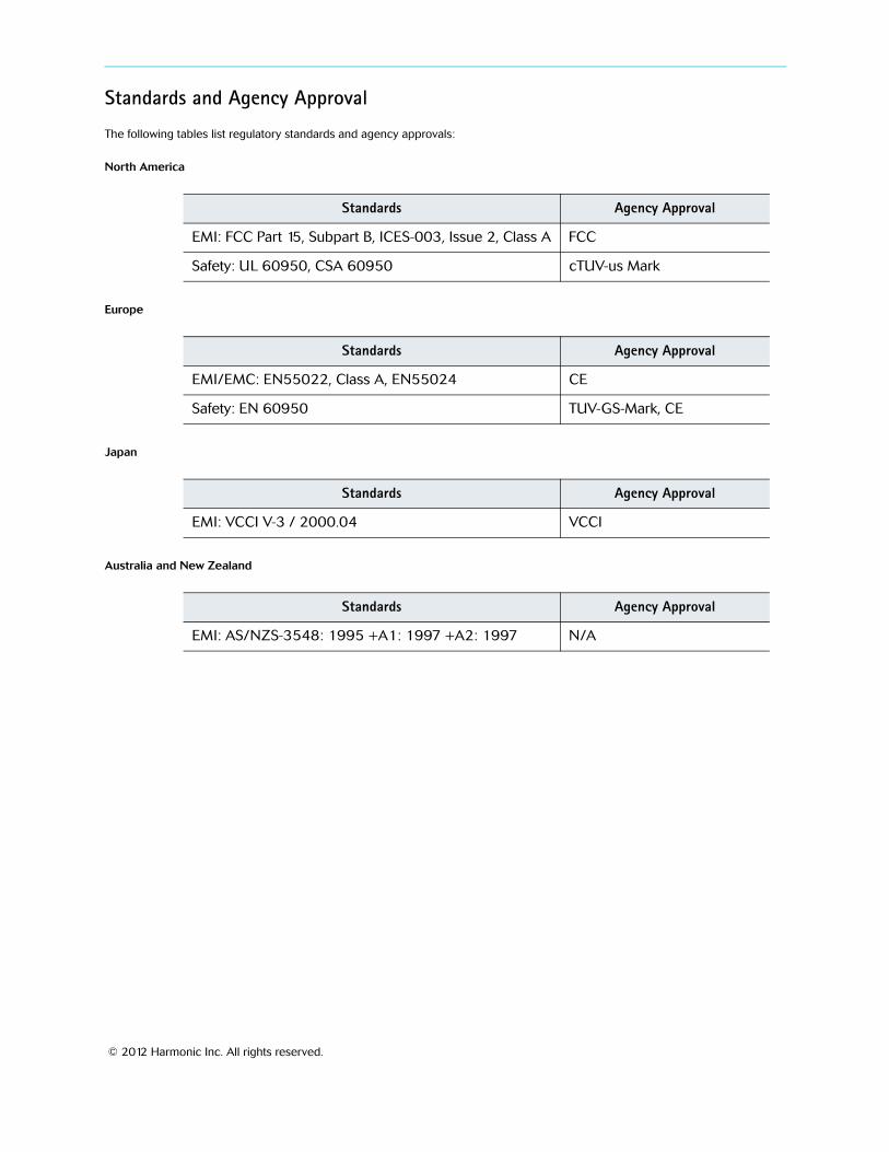
Standards and Agency Approval
The following tables list regulatory standards and agency approvals:
North America
Europe
Japan
Australia and New Zealand
Standards Agency Approval
EMI: FCC Part 15, Subpart B, ICES-003, Issue 2, Class A FCC
Safety: UL 60950, CSA 60950 cTUV-us Mark
Standards Agency Approval
EMI/EMC: EN55022, Class A, EN55024 CE
Safety: EN 60950 TUV-GS-Mark, CE
Standards Agency Approval
EMI: VCCI V-3 / 2000.04 VCCI
Standards Agency Approval
EMI: AS/NZS-3548: 1995 +A1: 1997 +A2: 1997 N/A

© 2012 Harmonic Inc. All rights reserved.
Documentation ConventionsThis manual uses some special symbols and fonts to call your attention to important information. The following symbols appear throughout this manual:
DANGER: The Danger symbol calls your attention to information that, if ignored, can cause physical harm to you.
CAUTION: The Caution symbol calls your attention to information that, if ignored, can adversely affect the performance of your Harmonic product, or that can make a procedure needlessly difficult.
LASER DANGER: The Laser symbol and the Danger alert call your attention to information about the lasers in this product that, if ignored, can cause physical harm to you.
NOTE: The Note symbol calls your attention to additional information that you will benefit from heeding. It may be used to call attention to an especially important piece of information you need, or it may provide additional information that applies in only some carefully delineated circumstances.
TIP: The Tip symbol calls your attention to parenthetical information that is not necessary for performing a given procedure, but which, if followed, might make the procedure or its subsequent steps easier, smoother, or more efficient.
NOTE: You require Adobe Reader or Adobe Acrobat version 6.0 or later to open the PDF files. You can download Adobe Reader free of charge from www.adobe.com.
Table of Contents
© 2012 Harmonic Inc. 6 Ellipse r.2.14, Revision A
Table of Contents
Chapter 1 Introduction1.1 Operating Environment . . . . . . . . . . . . . . . . . . . . . . . . . . . . . . . . . . . . . . . . . . . . . . . 111.2 Applications and General Features . . . . . . . . . . . . . . . . . . . . . . . . . . . . . . . . . . . . . 11
1.2.1 Ellipse 1000 SD/HD Contribution Encoder . . . . . . . . . . . . . . . . . . . . . . . . . . . . . . . 121.2.2 Ellipse 2000 DSNG SD/HD Contribution Encoder . . . . . . . . . . . . . . . . . . . . . . . . . . 13
1.3 Management . . . . . . . . . . . . . . . . . . . . . . . . . . . . . . . . . . . . . . . . . . . . . . . . . . . . . . . 141.3.1 Local Management . . . . . . . . . . . . . . . . . . . . . . . . . . . . . . . . . . . . . . . . . . . . . . . . . . 141.3.2 Remote Management . . . . . . . . . . . . . . . . . . . . . . . . . . . . . . . . . . . . . . . . . . . . . . . . 14
1.4 Mechanical Structure . . . . . . . . . . . . . . . . . . . . . . . . . . . . . . . . . . . . . . . . . . . . . . . . 151.4.1 Front Panel. . . . . . . . . . . . . . . . . . . . . . . . . . . . . . . . . . . . . . . . . . . . . . . . . . . . . . . . . 151.4.2 Ellipse Rear Panel . . . . . . . . . . . . . . . . . . . . . . . . . . . . . . . . . . . . . . . . . . . . . . . . . . . 16
Chapter 2 Initial Configuration and Basic Operation2.1 Web Configuration . . . . . . . . . . . . . . . . . . . . . . . . . . . . . . . . . . . . . . . . . . . . . . . . . . 21
2.1.1 Encoder and Modulator Status Monitoring. . . . . . . . . . . . . . . . . . . . . . . . . . . . . . . 232.2 Ellipse Set-Up Procedures. . . . . . . . . . . . . . . . . . . . . . . . . . . . . . . . . . . . . . . . . . . . . 26
2.2.1 MPEG-4 Ultra Low Latency Mode Set-up Procedure . . . . . . . . . . . . . . . . . . . . . . . 272.2.2 DVB-S2 L-Band Modulator Setup Procedure . . . . . . . . . . . . . . . . . . . . . . . . . . . . . 292.2.3 MPEG-2 Analog Transport Stream Configuration. . . . . . . . . . . . . . . . . . . . . . . . . . 312.2.4 MPEG-4 HD Transport Stream Configuration . . . . . . . . . . . . . . . . . . . . . . . . . . . . . 34
Chapter 3 Ellipse Management3.1 Ellipse Management Interfaces . . . . . . . . . . . . . . . . . . . . . . . . . . . . . . . . . . . . . . . . 37
3.1.1 Ellipse Front Panel Control Interface . . . . . . . . . . . . . . . . . . . . . . . . . . . . . . . . . . . . 373.1.2 Ellipse Web Management Control Interface . . . . . . . . . . . . . . . . . . . . . . . . . . . . . . 44
3.2 Ellipse Management Menu Tree . . . . . . . . . . . . . . . . . . . . . . . . . . . . . . . . . . . . . . . . 473.2.1 Front Panel Top Menu . . . . . . . . . . . . . . . . . . . . . . . . . . . . . . . . . . . . . . . . . . . . . . . . 473.2.2 Web Manager Main Screen . . . . . . . . . . . . . . . . . . . . . . . . . . . . . . . . . . . . . . . . . . . 49
3.3 Preset Menu. . . . . . . . . . . . . . . . . . . . . . . . . . . . . . . . . . . . . . . . . . . . . . . . . . . . . . . . 513.3.1 Recall Preset Files Menu . . . . . . . . . . . . . . . . . . . . . . . . . . . . . . . . . . . . . . . . . . . . . . 523.3.2 Save Current Preset Menu . . . . . . . . . . . . . . . . . . . . . . . . . . . . . . . . . . . . . . . . . . . . 533.3.3 Delete Menu. . . . . . . . . . . . . . . . . . . . . . . . . . . . . . . . . . . . . . . . . . . . . . . . . . . . . . . . 553.3.4 Rename Menu . . . . . . . . . . . . . . . . . . . . . . . . . . . . . . . . . . . . . . . . . . . . . . . . . . . . . . 56
3.4 Configuration Menu . . . . . . . . . . . . . . . . . . . . . . . . . . . . . . . . . . . . . . . . . . . . . . . . . 573.5 Status Menu. . . . . . . . . . . . . . . . . . . . . . . . . . . . . . . . . . . . . . . . . . . . . . . . . . . . . . . . 59
3.5.1 Service and PID Table . . . . . . . . . . . . . . . . . . . . . . . . . . . . . . . . . . . . . . . . . . . . . . . . 613.5.2 Permissions . . . . . . . . . . . . . . . . . . . . . . . . . . . . . . . . . . . . . . . . . . . . . . . . . . . . . . . . 623.5.3 Alarm Status . . . . . . . . . . . . . . . . . . . . . . . . . . . . . . . . . . . . . . . . . . . . . . . . . . . . . . . 633.5.4 Access Authorizations . . . . . . . . . . . . . . . . . . . . . . . . . . . . . . . . . . . . . . . . . . . . . . . . 64
Chapter 4 Transport Stream Configuration4.1 TS General Menu/Tab . . . . . . . . . . . . . . . . . . . . . . . . . . . . . . . . . . . . . . . . . . . . . . . . 67
4.1.1 Broadcast Standard . . . . . . . . . . . . . . . . . . . . . . . . . . . . . . . . . . . . . . . . . . . . . . . . . . 68
Table of Contents
© 2012 Harmonic Inc. 7 Ellipse r.2.14, Revision A
4.1.2 Packet Length . . . . . . . . . . . . . . . . . . . . . . . . . . . . . . . . . . . . . . . . . . . . . . . . . . . . . . 694.1.3 Scrambling Mode. . . . . . . . . . . . . . . . . . . . . . . . . . . . . . . . . . . . . . . . . . . . . . . . . . . . 70
4.2 DVB-ASI Interface Menu. . . . . . . . . . . . . . . . . . . . . . . . . . . . . . . . . . . . . . . . . . . . . . 714.2.1 Output Rate . . . . . . . . . . . . . . . . . . . . . . . . . . . . . . . . . . . . . . . . . . . . . . . . . . . . . . . . 724.2.2 Transport Stream ID . . . . . . . . . . . . . . . . . . . . . . . . . . . . . . . . . . . . . . . . . . . . . . . . . 734.2.3 Network ID . . . . . . . . . . . . . . . . . . . . . . . . . . . . . . . . . . . . . . . . . . . . . . . . . . . . . . . . . 734.2.4 Network Name. . . . . . . . . . . . . . . . . . . . . . . . . . . . . . . . . . . . . . . . . . . . . . . . . . . . . . 74
4.3 M-SPTS Menu/Tab . . . . . . . . . . . . . . . . . . . . . . . . . . . . . . . . . . . . . . . . . . . . . . . . . . . 744.3.1 M-SPTS Stream Management . . . . . . . . . . . . . . . . . . . . . . . . . . . . . . . . . . . . . . . . . 744.3.2 M-SPTS Configuration Management . . . . . . . . . . . . . . . . . . . . . . . . . . . . . . . . . . . . 78
4.4 Services Menu . . . . . . . . . . . . . . . . . . . . . . . . . . . . . . . . . . . . . . . . . . . . . . . . . . . . . . 844.4.1 TS Service Management . . . . . . . . . . . . . . . . . . . . . . . . . . . . . . . . . . . . . . . . . . . . . . 854.4.2 TS Service Configuration. . . . . . . . . . . . . . . . . . . . . . . . . . . . . . . . . . . . . . . . . . . . . . 884.4.3 TS Scrambling Management. . . . . . . . . . . . . . . . . . . . . . . . . . . . . . . . . . . . . . . . . . . 914.4.4 Add and Drop PID . . . . . . . . . . . . . . . . . . . . . . . . . . . . . . . . . . . . . . . . . . . . . . . . . . . 98
4.5 SI Tables Menu/Tab . . . . . . . . . . . . . . . . . . . . . . . . . . . . . . . . . . . . . . . . . . . . . . . . . 1004.5.1 General . . . . . . . . . . . . . . . . . . . . . . . . . . . . . . . . . . . . . . . . . . . . . . . . . . . . . . . . . . . 1014.5.2 MPEG . . . . . . . . . . . . . . . . . . . . . . . . . . . . . . . . . . . . . . . . . . . . . . . . . . . . . . . . . . . . 1034.5.3 PSI-SI . . . . . . . . . . . . . . . . . . . . . . . . . . . . . . . . . . . . . . . . . . . . . . . . . . . . . . . . . . . . 1044.5.4 Carrier ID . . . . . . . . . . . . . . . . . . . . . . . . . . . . . . . . . . . . . . . . . . . . . . . . . . . . . . . . . 1054.5.5 Satellite Delivery Descriptor . . . . . . . . . . . . . . . . . . . . . . . . . . . . . . . . . . . . . . . . . . 106
4.6 DPI Menu . . . . . . . . . . . . . . . . . . . . . . . . . . . . . . . . . . . . . . . . . . . . . . . . . . . . . . . . . 107
Chapter 5 Video Configuration5.1 Video Input. . . . . . . . . . . . . . . . . . . . . . . . . . . . . . . . . . . . . . . . . . . . . . . . . . . . . . . . 112
5.1.1 Video Standard (SDI and CV Video Inputs) . . . . . . . . . . . . . . . . . . . . . . . . . . . . . . 1145.1.2 Video Test Pattern . . . . . . . . . . . . . . . . . . . . . . . . . . . . . . . . . . . . . . . . . . . . . . . . . . 1165.1.3 Aspect Ratio. . . . . . . . . . . . . . . . . . . . . . . . . . . . . . . . . . . . . . . . . . . . . . . . . . . . . . . 1175.1.4 VBI . . . . . . . . . . . . . . . . . . . . . . . . . . . . . . . . . . . . . . . . . . . . . . . . . . . . . . . . . . . . . . 1185.1.5 Analog Interface . . . . . . . . . . . . . . . . . . . . . . . . . . . . . . . . . . . . . . . . . . . . . . . . . . . 125
5.2 Video Engine . . . . . . . . . . . . . . . . . . . . . . . . . . . . . . . . . . . . . . . . . . . . . . . . . . . . . . 1325.2.1 General Menu . . . . . . . . . . . . . . . . . . . . . . . . . . . . . . . . . . . . . . . . . . . . . . . . . . . . . 1355.2.2 CBR Menu . . . . . . . . . . . . . . . . . . . . . . . . . . . . . . . . . . . . . . . . . . . . . . . . . . . . . . . . 1455.2.3 Capped-VBR Menu . . . . . . . . . . . . . . . . . . . . . . . . . . . . . . . . . . . . . . . . . . . . . . . . . 1465.2.4 MPEG-2 Advanced Menu . . . . . . . . . . . . . . . . . . . . . . . . . . . . . . . . . . . . . . . . . . . . 1485.2.5 MPEG-4 AVC (H.264) Advanced Menu . . . . . . . . . . . . . . . . . . . . . . . . . . . . . . . . . 1555.2.6 CC Option . . . . . . . . . . . . . . . . . . . . . . . . . . . . . . . . . . . . . . . . . . . . . . . . . . . . . . . . . 1625.2.7 Logo Insertion . . . . . . . . . . . . . . . . . . . . . . . . . . . . . . . . . . . . . . . . . . . . . . . . . . . . . 1665.2.8 Slide Insertion . . . . . . . . . . . . . . . . . . . . . . . . . . . . . . . . . . . . . . . . . . . . . . . . . . . . . 168
Chapter 6 Audio Configuration6.1 General . . . . . . . . . . . . . . . . . . . . . . . . . . . . . . . . . . . . . . . . . . . . . . . . . . . . . . . . . . . 1726.2 Audio General Menu . . . . . . . . . . . . . . . . . . . . . . . . . . . . . . . . . . . . . . . . . . . . . . . . 176
6.2.1 Coding Scheme . . . . . . . . . . . . . . . . . . . . . . . . . . . . . . . . . . . . . . . . . . . . . . . . . . . . 1776.2.2 Source. . . . . . . . . . . . . . . . . . . . . . . . . . . . . . . . . . . . . . . . . . . . . . . . . . . . . . . . . . . . 1786.2.3 Test Tone . . . . . . . . . . . . . . . . . . . . . . . . . . . . . . . . . . . . . . . . . . . . . . . . . . . . . . . . . 1796.2.4 Volume . . . . . . . . . . . . . . . . . . . . . . . . . . . . . . . . . . . . . . . . . . . . . . . . . . . . . . . . . . . 180
Table of Contents
© 2012 Harmonic Inc. 8 Ellipse r.2.14, Revision A
6.2.5 Max Input Level . . . . . . . . . . . . . . . . . . . . . . . . . . . . . . . . . . . . . . . . . . . . . . . . . . . . 1816.2.6 Impedance . . . . . . . . . . . . . . . . . . . . . . . . . . . . . . . . . . . . . . . . . . . . . . . . . . . . . . . . 183
6.3 Channel Parameters Menu . . . . . . . . . . . . . . . . . . . . . . . . . . . . . . . . . . . . . . . . . . . 1846.3.1 Activation. . . . . . . . . . . . . . . . . . . . . . . . . . . . . . . . . . . . . . . . . . . . . . . . . . . . . . . . . 1846.3.2 PID . . . . . . . . . . . . . . . . . . . . . . . . . . . . . . . . . . . . . . . . . . . . . . . . . . . . . . . . . . . . . . 1856.3.3 Language . . . . . . . . . . . . . . . . . . . . . . . . . . . . . . . . . . . . . . . . . . . . . . . . . . . . . . . . . 186
6.4 SDI Embedded Parameters . . . . . . . . . . . . . . . . . . . . . . . . . . . . . . . . . . . . . . . . . . . 1866.4.1 Group . . . . . . . . . . . . . . . . . . . . . . . . . . . . . . . . . . . . . . . . . . . . . . . . . . . . . . . . . . . . 1896.4.2 Channel . . . . . . . . . . . . . . . . . . . . . . . . . . . . . . . . . . . . . . . . . . . . . . . . . . . . . . . . . . 190
6.5 Coding Scheme Configuration . . . . . . . . . . . . . . . . . . . . . . . . . . . . . . . . . . . . . . . . 1916.5.1 MPEG-1 Layer 2 Parameters. . . . . . . . . . . . . . . . . . . . . . . . . . . . . . . . . . . . . . . . . . 1926.5.2 Dolby Digital 2.0 Parameters . . . . . . . . . . . . . . . . . . . . . . . . . . . . . . . . . . . . . . . . . 2016.5.3 Dolby Digital 2.0 and Dolby Digital 5.1 Pre-Processing . . . . . . . . . . . . . . . . . . . . 2116.5.4 MPEG-2 AAC LC Parameters. . . . . . . . . . . . . . . . . . . . . . . . . . . . . . . . . . . . . . . . . . 2166.5.5 MPEG-4 HE AAC Parameters . . . . . . . . . . . . . . . . . . . . . . . . . . . . . . . . . . . . . . . . . 2206.5.6 Dolby Digital 5.1 . . . . . . . . . . . . . . . . . . . . . . . . . . . . . . . . . . . . . . . . . . . . . . . . . . . 2266.5.7 Dolby Digital Pass Through Parameters . . . . . . . . . . . . . . . . . . . . . . . . . . . . . . . . . 2366.5.8 Dolby E Pass Through Parameters Menu . . . . . . . . . . . . . . . . . . . . . . . . . . . . . . . . 2406.5.9 Linear PCM Pass Through Parameters Menu. . . . . . . . . . . . . . . . . . . . . . . . . . . . . 244
6.6 Cue Tone Parameters. . . . . . . . . . . . . . . . . . . . . . . . . . . . . . . . . . . . . . . . . . . . . . . . 248
Chapter 7 Output Interface Configuration7.1 General . . . . . . . . . . . . . . . . . . . . . . . . . . . . . . . . . . . . . . . . . . . . . . . . . . . . . . . . . . . 2507.2 IP Output Menu . . . . . . . . . . . . . . . . . . . . . . . . . . . . . . . . . . . . . . . . . . . . . . . . . . . . 251
7.2.1 DVBoIP1 (DVBoIP2) Menu. . . . . . . . . . . . . . . . . . . . . . . . . . . . . . . . . . . . . . . . . . . . 2527.2.2 IP Output Activation Menu. . . . . . . . . . . . . . . . . . . . . . . . . . . . . . . . . . . . . . . . . . . 255
7.3 ASI Output Menu. . . . . . . . . . . . . . . . . . . . . . . . . . . . . . . . . . . . . . . . . . . . . . . . . . . 256
Chapter 8 Input Interface Configuration8.1 General . . . . . . . . . . . . . . . . . . . . . . . . . . . . . . . . . . . . . . . . . . . . . . . . . . . . . . . . . . . 2588.2 DVB-ASI Input . . . . . . . . . . . . . . . . . . . . . . . . . . . . . . . . . . . . . . . . . . . . . . . . . . . . . 259
8.2.1 Rate (DVB-ASI Input / Cascading) . . . . . . . . . . . . . . . . . . . . . . . . . . . . . . . . . . . . . 2608.2.2 Activation (DVB-ASI Input / Cascading) . . . . . . . . . . . . . . . . . . . . . . . . . . . . . . . . 2618.2.3 Scrambling (DVB-ASI Input / Cascading). . . . . . . . . . . . . . . . . . . . . . . . . . . . . . . . 261
8.3 IP Input Menu (MPE input) . . . . . . . . . . . . . . . . . . . . . . . . . . . . . . . . . . . . . . . . . . . 2628.3.1 MPE Menu . . . . . . . . . . . . . . . . . . . . . . . . . . . . . . . . . . . . . . . . . . . . . . . . . . . . . . . . 2638.3.2 Port Configuration Menu . . . . . . . . . . . . . . . . . . . . . . . . . . . . . . . . . . . . . . . . . . . . 265
8.4 Serial (Low Speed Data) Input Menu . . . . . . . . . . . . . . . . . . . . . . . . . . . . . . . . . . . 2668.4.1 LSD Activation Menu. . . . . . . . . . . . . . . . . . . . . . . . . . . . . . . . . . . . . . . . . . . . . . . . 2688.4.2 LSD PID Setup Menu . . . . . . . . . . . . . . . . . . . . . . . . . . . . . . . . . . . . . . . . . . . . . . . . 2688.4.3 LSD Rate Setup Menu . . . . . . . . . . . . . . . . . . . . . . . . . . . . . . . . . . . . . . . . . . . . . . . 2698.4.4 LSD Timeout Setup Menu . . . . . . . . . . . . . . . . . . . . . . . . . . . . . . . . . . . . . . . . . . . . 2698.4.5 LSD End Of File (EOF) Character Setup Menu . . . . . . . . . . . . . . . . . . . . . . . . . . . . 270
Chapter 9 Unit Configuration9.1 General . . . . . . . . . . . . . . . . . . . . . . . . . . . . . . . . . . . . . . . . . . . . . . . . . . . . . . . . . . . 2719.2 Licensing . . . . . . . . . . . . . . . . . . . . . . . . . . . . . . . . . . . . . . . . . . . . . . . . . . . . . . . . . 273
Table of Contents
© 2012 Harmonic Inc. 9 Ellipse r.2.14, Revision A
9.2.1 Device ID . . . . . . . . . . . . . . . . . . . . . . . . . . . . . . . . . . . . . . . . . . . . . . . . . . . . . . . . . 2749.2.2 License Key. . . . . . . . . . . . . . . . . . . . . . . . . . . . . . . . . . . . . . . . . . . . . . . . . . . . . . . . 275
9.3 Ellipse System Menu/Tab . . . . . . . . . . . . . . . . . . . . . . . . . . . . . . . . . . . . . . . . . . . . 2769.3.1 Description Menu . . . . . . . . . . . . . . . . . . . . . . . . . . . . . . . . . . . . . . . . . . . . . . . . . . 2779.3.2 Version Information Menu . . . . . . . . . . . . . . . . . . . . . . . . . . . . . . . . . . . . . . . . . . . 2809.3.3 System Clock . . . . . . . . . . . . . . . . . . . . . . . . . . . . . . . . . . . . . . . . . . . . . . . . . . . . . . 2819.3.4 Administration . . . . . . . . . . . . . . . . . . . . . . . . . . . . . . . . . . . . . . . . . . . . . . . . . . . . . 2829.3.5 Ethernet Port (Management) Menu. . . . . . . . . . . . . . . . . . . . . . . . . . . . . . . . . . . . 2859.3.6 Serial Port (Management) Menu . . . . . . . . . . . . . . . . . . . . . . . . . . . . . . . . . . . . . . 2889.3.7 Date Menu . . . . . . . . . . . . . . . . . . . . . . . . . . . . . . . . . . . . . . . . . . . . . . . . . . . . . . . . 2899.3.8 Front Panel Control . . . . . . . . . . . . . . . . . . . . . . . . . . . . . . . . . . . . . . . . . . . . . . . . . 2909.3.9 BOOTP Control Menu . . . . . . . . . . . . . . . . . . . . . . . . . . . . . . . . . . . . . . . . . . . . . . . 291
9.4 SNMP Traps Menu . . . . . . . . . . . . . . . . . . . . . . . . . . . . . . . . . . . . . . . . . . . . . . . . . . 2929.4.1 Traps Destination List . . . . . . . . . . . . . . . . . . . . . . . . . . . . . . . . . . . . . . . . . . . . . . . 2939.4.2 Add Entry Menu (front panel). . . . . . . . . . . . . . . . . . . . . . . . . . . . . . . . . . . . . . . . . 2969.4.3 Drop Entry Menu (front panel) . . . . . . . . . . . . . . . . . . . . . . . . . . . . . . . . . . . . . . . . 2979.4.4 Adding and Dropping Entries (Web Manager). . . . . . . . . . . . . . . . . . . . . . . . . . . . 298
9.5 Alarm Menu/Tab . . . . . . . . . . . . . . . . . . . . . . . . . . . . . . . . . . . . . . . . . . . . . . . . . . . 2999.6 Redundancy Menu/Tab . . . . . . . . . . . . . . . . . . . . . . . . . . . . . . . . . . . . . . . . . . . . . . 3049.7 Display Contrast Menu . . . . . . . . . . . . . . . . . . . . . . . . . . . . . . . . . . . . . . . . . . . . . . 306
Chapter 10 DSNG Configuration 10.1 General . . . . . . . . . . . . . . . . . . . . . . . . . . . . . . . . . . . . . . . . . . . . . . . . . . . . . . . . . . . 30710.2 L-Band Modulator Parameters . . . . . . . . . . . . . . . . . . . . . . . . . . . . . . . . . . . . . . . . 309
10.2.1 Carrier. . . . . . . . . . . . . . . . . . . . . . . . . . . . . . . . . . . . . . . . . . . . . . . . . . . . . . . . . . . . 31110.2.2 L-Band Power . . . . . . . . . . . . . . . . . . . . . . . . . . . . . . . . . . . . . . . . . . . . . . . . . . . . . 31210.2.3 Reduced L-Band Power . . . . . . . . . . . . . . . . . . . . . . . . . . . . . . . . . . . . . . . . . . . . . . 31310.2.4 TX RF Frequency. . . . . . . . . . . . . . . . . . . . . . . . . . . . . . . . . . . . . . . . . . . . . . . . . . . . 31410.2.5 RF Conv. LO Frequency . . . . . . . . . . . . . . . . . . . . . . . . . . . . . . . . . . . . . . . . . . . . . . 31510.2.6 L-Band Frequency . . . . . . . . . . . . . . . . . . . . . . . . . . . . . . . . . . . . . . . . . . . . . . . . . . 31510.2.7 Remote Power 24 VDC . . . . . . . . . . . . . . . . . . . . . . . . . . . . . . . . . . . . . . . . . . . . . . 31610.2.8 10 MHz Clock. . . . . . . . . . . . . . . . . . . . . . . . . . . . . . . . . . . . . . . . . . . . . . . . . . . . . . 316
10.3 IF Modulator Parameters . . . . . . . . . . . . . . . . . . . . . . . . . . . . . . . . . . . . . . . . . . . . 31710.3.1 IF Power . . . . . . . . . . . . . . . . . . . . . . . . . . . . . . . . . . . . . . . . . . . . . . . . . . . . . . . . . . 32010.3.2 IF Frequency. . . . . . . . . . . . . . . . . . . . . . . . . . . . . . . . . . . . . . . . . . . . . . . . . . . . . . . 32010.3.3 L-Band Monitor Frequency . . . . . . . . . . . . . . . . . . . . . . . . . . . . . . . . . . . . . . . . . . . 32110.3.4 Output Impedance. . . . . . . . . . . . . . . . . . . . . . . . . . . . . . . . . . . . . . . . . . . . . . . . . . 321
10.4 Common Modulation Parameters . . . . . . . . . . . . . . . . . . . . . . . . . . . . . . . . . . . . . 32210.4.1 Modulation On/Off . . . . . . . . . . . . . . . . . . . . . . . . . . . . . . . . . . . . . . . . . . . . . . . . . 32210.4.2 Symbol Rate . . . . . . . . . . . . . . . . . . . . . . . . . . . . . . . . . . . . . . . . . . . . . . . . . . . . . . . 32310.4.3 Spectrum Inversion . . . . . . . . . . . . . . . . . . . . . . . . . . . . . . . . . . . . . . . . . . . . . . . . . 32310.4.4 Modulation Scheme . . . . . . . . . . . . . . . . . . . . . . . . . . . . . . . . . . . . . . . . . . . . . . . . 32410.4.5 FEC and Modulation . . . . . . . . . . . . . . . . . . . . . . . . . . . . . . . . . . . . . . . . . . . . . . . . 32510.4.6 Frame Length . . . . . . . . . . . . . . . . . . . . . . . . . . . . . . . . . . . . . . . . . . . . . . . . . . . . . . 32610.4.7 Operating Mode. . . . . . . . . . . . . . . . . . . . . . . . . . . . . . . . . . . . . . . . . . . . . . . . . . . . 32710.4.8 Roll-Off Factor. . . . . . . . . . . . . . . . . . . . . . . . . . . . . . . . . . . . . . . . . . . . . . . . . . . . . 32810.4.9 Pilot Mode . . . . . . . . . . . . . . . . . . . . . . . . . . . . . . . . . . . . . . . . . . . . . . . . . . . . . . . . 328
Table of Contents
© 2012 Harmonic Inc. 10 Ellipse r.2.14, Revision A
Chapter 11 Contacting Harmonic Support
Appendix A Characteristics and CapabilitiesA.1 Encoder Inputs . . . . . . . . . . . . . . . . . . . . . . . . . . . . . . . . . . . . . . . . . . . . . . . . . . . . 331A.2 Encoder Outputs . . . . . . . . . . . . . . . . . . . . . . . . . . . . . . . . . . . . . . . . . . . . . . . . . . . 332A.3 Modulator Characteristics (Ellipse 2000) . . . . . . . . . . . . . . . . . . . . . . . . . . . . . . . 332A.4 Processing Capabilities . . . . . . . . . . . . . . . . . . . . . . . . . . . . . . . . . . . . . . . . . . . . . 333A.5 Storage . . . . . . . . . . . . . . . . . . . . . . . . . . . . . . . . . . . . . . . . . . . . . . . . . . . . . . . . . . 335A.6 Control and Monitoring . . . . . . . . . . . . . . . . . . . . . . . . . . . . . . . . . . . . . . . . . . . . . 335A.7 BIT (Built In Tests): . . . . . . . . . . . . . . . . . . . . . . . . . . . . . . . . . . . . . . . . . . . . . . . . . 335A.8 Power and Physical Specifications: . . . . . . . . . . . . . . . . . . . . . . . . . . . . . . . . . . . . 335A.9 Phase Noise . . . . . . . . . . . . . . . . . . . . . . . . . . . . . . . . . . . . . . . . . . . . . . . . . . . . . . . 337
Appendix B Software Upgrade Using FTPB.1 Ellipse Setup IP . . . . . . . . . . . . . . . . . . . . . . . . . . . . . . . . . . . . . . . . . . . . . . . . . . . . 338B.2 PC FTP Application . . . . . . . . . . . . . . . . . . . . . . . . . . . . . . . . . . . . . . . . . . . . . . . . . 338B.3 Download Preparations . . . . . . . . . . . . . . . . . . . . . . . . . . . . . . . . . . . . . . . . . . . . . 338B.4 Loading the Software through FTP . . . . . . . . . . . . . . . . . . . . . . . . . . . . . . . . . . . . 339
B.4.1 Logon . . . . . . . . . . . . . . . . . . . . . . . . . . . . . . . . . . . . . . . . . . . . . . . . . . . . . . . . . . . . 340B.4.2 Delete Encoder’s Database . . . . . . . . . . . . . . . . . . . . . . . . . . . . . . . . . . . . . . . . . . . 341B.4.3 Loading the File . . . . . . . . . . . . . . . . . . . . . . . . . . . . . . . . . . . . . . . . . . . . . . . . . . . 343
Appendix C Database CloningC.1 Ellipse Setup IP . . . . . . . . . . . . . . . . . . . . . . . . . . . . . . . . . . . . . . . . . . . . . . . . . . . . 345C.2 Download Preparations . . . . . . . . . . . . . . . . . . . . . . . . . . . . . . . . . . . . . . . . . . . . . 345C.3 PC FTP Application . . . . . . . . . . . . . . . . . . . . . . . . . . . . . . . . . . . . . . . . . . . . . . . . . 345C.4 Updating Database through FTP . . . . . . . . . . . . . . . . . . . . . . . . . . . . . . . . . . . . . . 345
C.4.1 Logon . . . . . . . . . . . . . . . . . . . . . . . . . . . . . . . . . . . . . . . . . . . . . . . . . . . . . . . . . . . . 347C.4.2 Cloning the File . . . . . . . . . . . . . . . . . . . . . . . . . . . . . . . . . . . . . . . . . . . . . . . . . . . 348
Appendix D Audio Pass Through Schemes Set-Up
Appendix E DS9034PCX PowerCap
Appendix F Ellipse Logo/Slide CreatorF.1 General . . . . . . . . . . . . . . . . . . . . . . . . . . . . . . . . . . . . . . . . . . . . . . . . . . . . . . . . . . 354F.2 Logo/Slide Bitmap File Parameters . . . . . . . . . . . . . . . . . . . . . . . . . . . . . . . . . . . . 354F.3 Ellipse Logo/Slide Creator Installation . . . . . . . . . . . . . . . . . . . . . . . . . . . . . . . . . 354F.4 Ellipse Logo/Slide Creator Operation . . . . . . . . . . . . . . . . . . . . . . . . . . . . . . . . . . 355
Appendix G How to Connect an Ellipse to a Redundancy SwitchG.1 Connecting the Devices . . . . . . . . . . . . . . . . . . . . . . . . . . . . . . . . . . . . . . . . . . . . . 357
Glossary
© 2012 Harmonic Inc. 11 Ellipse r.2.14, Revision A
Chapter 1Introduction
The Harmonic Ellipse Series of Contribution Encoders presents an advanced concept in video compression. The Contribution Encoder platform provides broadcasters with multiple simultaneous MPEG-2 or MPEG-4/AVC (H.264) video encoding and DSNG modulation.
Topics:
Operating Environment
Applications and General Features
Management
Mechanical Structure
1.1 Operating EnvironmentThe versatile Ellipse series provides a universal solution for current and future contribution encoding needs. The platform enables a smooth migration path from MPEG-2 to MPEG-4/AVC (H.264), allowing either or both encoding formats to be transmitted concurrently over DVB-ASI and IP networks with the capability of DSNG modulation.
1.2 Applications and General FeaturesThe available modules in the Ellipse Series are:
Ellipse 1000 – SD/HD Contribution Encoder Ellipse 2000 – SD/HD DSNG Encoder
The following paragraphs describe the application of each Ellipse Series member and detail its basic features, hardware upgrades and software-licensed features.
Chapter 1 Introduction Applications and General Features
© 2012 Harmonic Inc. 12 Ellipse r.2.14, Revision A
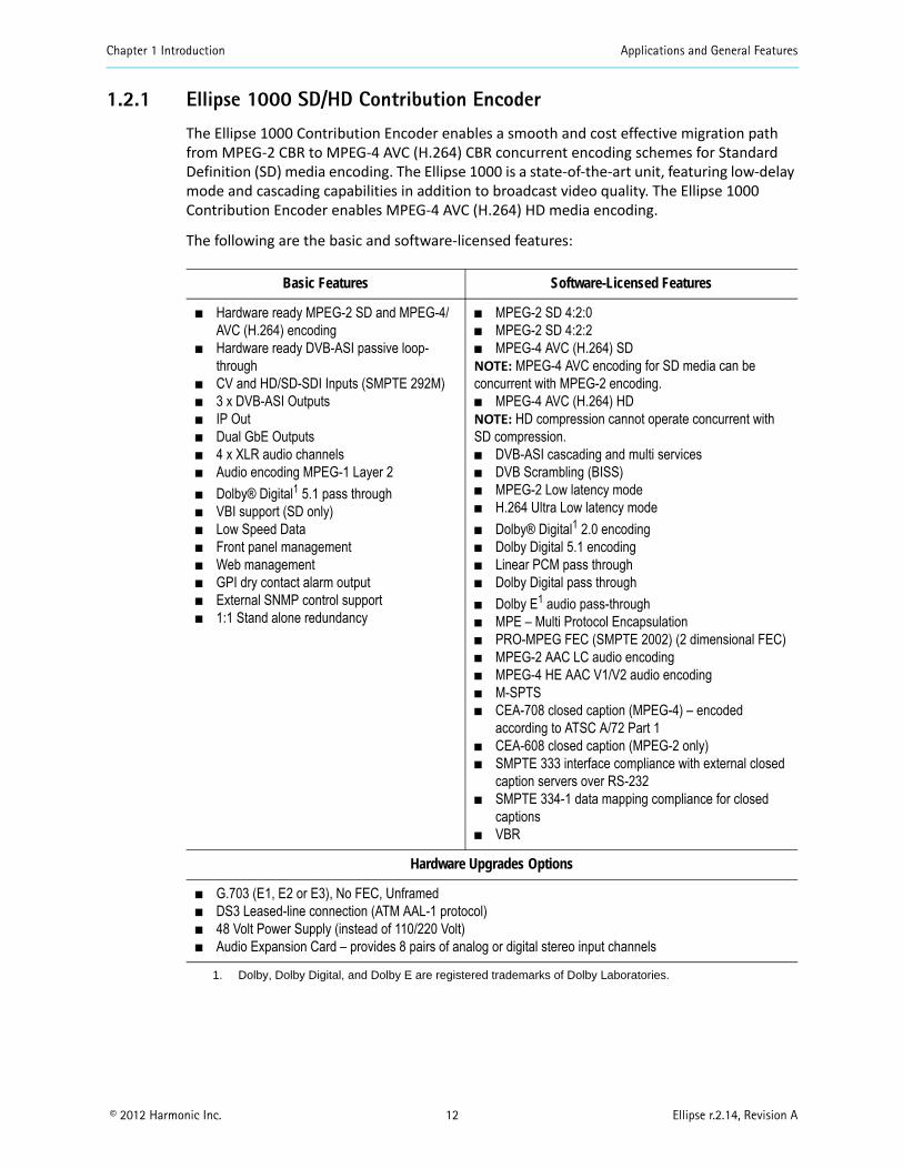
1.2.1 Ellipse 1000 SD/HD Contribution Encoder
The Ellipse 1000 Contribution Encoder enables a smooth and cost effective migration path from MPEG-2 CBR to MPEG-4 AVC (H.264) CBR concurrent encoding schemes for Standard Definition (SD) media encoding. The Ellipse 1000 is a state-of-the-art unit, featuring low-delay mode and cascading capabilities in addition to broadcast video quality. The Ellipse 1000 Contribution Encoder enables MPEG-4 AVC (H.264) HD media encoding.
The following are the basic and software-licensed features:
Basic Features Software-Licensed Features
Hardware ready MPEG-2 SD and MPEG-4/AVC (H.264) encoding
Hardware ready DVB-ASI passive loop-through
CV and HD/SD-SDI Inputs (SMPTE 292M) 3 x DVB-ASI Outputs IP Out Dual GbE Outputs 4 x XLR audio channels Audio encoding MPEG-1 Layer 2
Dolby® Digital1 5.1 pass through VBI support (SD only) Low Speed Data Front panel management Web management GPI dry contact alarm output External SNMP control support 1:1 Stand alone redundancy
1. Dolby, Dolby Digital, and Dolby E are registered trademarks of Dolby Laboratories.
MPEG-2 SD 4:2:0 MPEG-2 SD 4:2:2 MPEG-4 AVC (H.264) SD NOTE: MPEG-4 AVC encoding for SD media can be concurrent with MPEG-2 encoding. MPEG-4 AVC (H.264) HDNOTE: HD compression cannot operate concurrent with SD compression. DVB-ASI cascading and multi services DVB Scrambling (BISS) MPEG-2 Low latency mode H.264 Ultra Low latency mode
Dolby® Digital1 2.0 encoding Dolby Digital 5.1 encoding Linear PCM pass through Dolby Digital pass through
Dolby E1 audio pass-through MPE – Multi Protocol Encapsulation PRO-MPEG FEC (SMPTE 2002) (2 dimensional FEC) MPEG-2 AAC LC audio encoding MPEG-4 HE AAC V1/V2 audio encoding M-SPTS CEA-708 closed caption (MPEG-4) – encoded
according to ATSC A/72 Part 1 CEA-608 closed caption (MPEG-2 only) SMPTE 333 interface compliance with external closed
caption servers over RS-232 SMPTE 334-1 data mapping compliance for closed
captions VBR
Hardware Upgrades Options
G.703 (E1, E2 or E3), No FEC, Unframed DS3 Leased-line connection (ATM AAL-1 protocol) 48 Volt Power Supply (instead of 110/220 Volt) Audio Expansion Card – provides 8 pairs of analog or digital stereo input channels
Chapter 1 Introduction Applications and General Features
© 2012 Harmonic Inc. 13 Ellipse r.2.14, Revision A
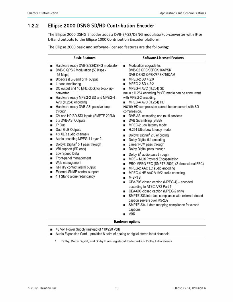
1.2.2 Ellipse 2000 DSNG SD/HD Contribution Encoder
The Ellipse 2000 DSNG Encoder adds a DVB-S/-S2/DSNG modulator/up-converter with IF or L-Band outputs to the Ellipse 1000 Contribution Encoder platform.
The Ellipse 2000 basic and software-licensed features are the following:
Basic Features Software-Licensed Features
Hardware ready DVB-S/S2/DSNG modulator DVB-S QPSK Modulation (50 Ksps -
15 Msps) Broadcast L-Band or IF output L-band monitoring DC output and 10 MHz clock for block up-
converter Hardware ready MPEG-2 SD and MPEG-4
AVC (H.264) encoding Hardware ready DVB-ASI passive loop-
through CV and HD/SD-SDI Inputs (SMPTE 292M) 3 x DVB-ASI Outputs IP Out Dual GbE Outputs 4 x XLR audio channels Audio encoding MPEG-1 Layer 2
Dolby® Digital1 5.1 pass through VBI support (SD only) Low Speed Data Front-panel management Web management GPI dry contact alarm output External SNMP control support 1:1 Stand alone redundancy
1. Dolby, Dolby Digital, and Dolby E are registered trademarks of Dolby Laboratories.
Modulation upgrade to: DVB-S2 QPSK/8PSK/16APSKDVB-DSNG QPSK/8PSK/16QAM
MPEG-2 SD 4:2:0 MPEG-2 SD 4:2:2 MPEG-4 AVC (H.264) SDNOTE: H.264 encoding for SD media can be concurrent with MPEG-2 encoding. MPEG-4 AVC (H.264) HDNOTE: HD compression cannot be concurrent with SD compression. DVB-ASI cascading and multi services DVB Scrambling (BISS) MPEG-2 Low latency mode H.264 Ultra Low latency mode
Dolby® Digital1 2.0 encoding Dolby Digital 5.1 encoding Linear PCM pass through Dolby Digital pass through
Dolby E1 audio pass through MPE – Multi Protocol Encapsulation PRO-MPEG FEC (SMPTE 2002) (2 dimensional FEC) MPEG-2 AAC LC audio encoding MPEG-4 HE AAC V1/V2 audio encoding M-SPTS CEA-708 closed caption (MPEG-4) – encoded
according to ATSC A/72 Part 1 CEA-608 closed caption (MPEG-2 only) SMPTE 333 interface compliance with external closed
caption servers over RS-232 SMPTE 334-1 data mapping compliance for closed
captions VBR
Hardware options
48 Volt Power Supply (instead of 110/220 Volt) Audio Expansion Card – provides 8 pairs of analog or digital stereo input channels
Chapter 1 Introduction Management
© 2012 Harmonic Inc. 14 Ellipse r.2.14, Revision A
1.3 ManagementThe following sections detail the different management interfaces and methods available to control the Ellipse.
1.3.1 Local Management
The Ellipse supports two local management methods:
Front-panel Control – Provides an easy to use graphical display with a large LCD screen and intuitive control.
PC Terminal Control – Supports PC terminal control from a standard PC terminal (over RS232). The terminal provides access to control and monitor functionalities that are not available when using any Ellipse front panel feature.
CAUTION: Using PC Terminal control option can be done only by advanced users and Harmonic technical support personnel.
1.3.2 Remote Management
The Ellipse supports three remote management methods:
Web Manager – Use Internet Explorer to monitor the Ellipse parameters with an easy to use graphical-interface.
NMS-/ SNMP Control – provides a menu and dialog driven interface which allows controlling, modifying, and upgrading the Ellipse though SNMP commands.
Telnet – supports remote control through the Internet. By that, it can be controlled and configured from a standard PC terminal (over Ethernet).
CAUTION: Telnet access is recommended to be used by advanced users and/or Harmonic technical support personnel.
Chapter 1 Introduction Mechanical Structure
© 2012 Harmonic Inc. 15 Ellipse r.2.14, Revision A
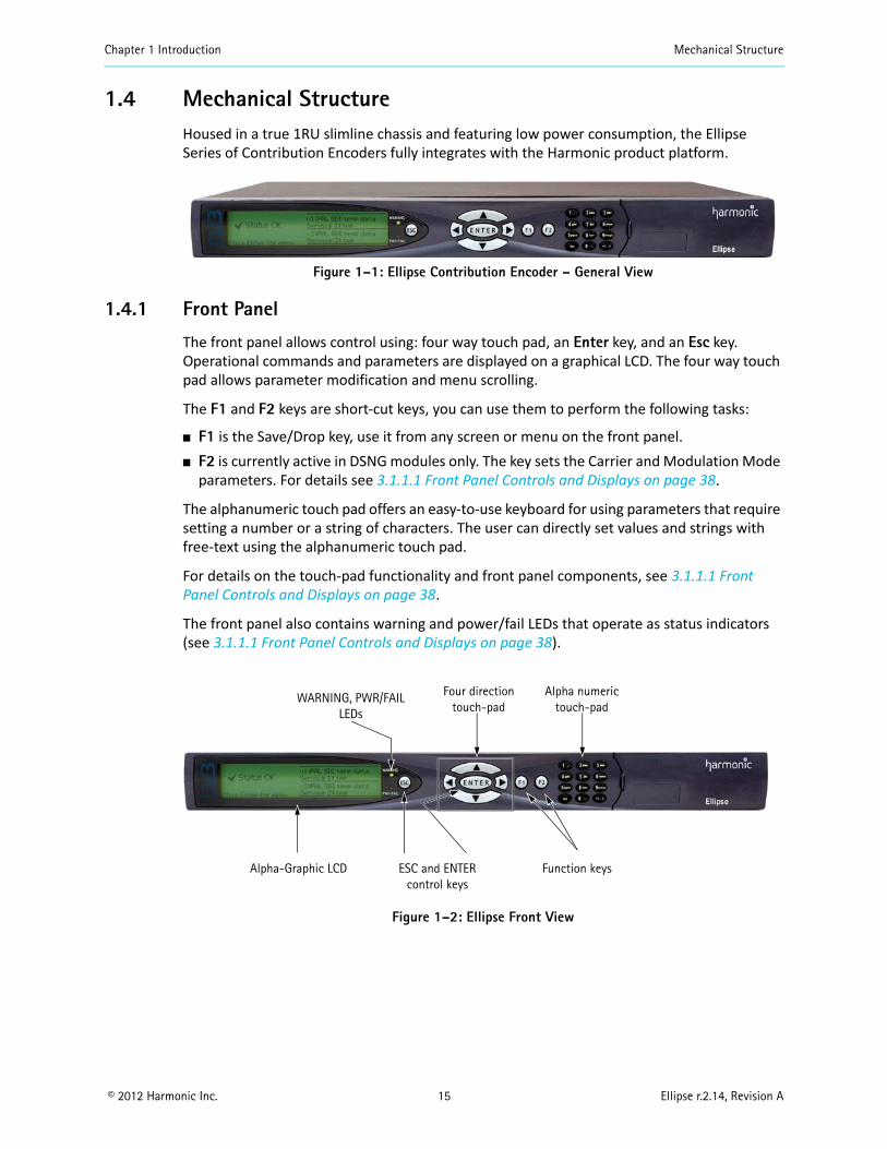
1.4 Mechanical StructureHoused in a true 1RU slimline chassis and featuring low power consumption, the Ellipse Series of Contribution Encoders fully integrates with the Harmonic product platform.
Figure 1–1: Ellipse Contribution Encoder – General View
1.4.1 Front Panel
The front panel allows control using: four way touch pad, an Enter key, and an Esc key. Operational commands and parameters are displayed on a graphical LCD. The four way touch pad allows parameter modification and menu scrolling.
The F1 and F2 keys are short-cut keys, you can use them to perform the following tasks:
F1 is the Save/Drop key, use it from any screen or menu on the front panel. F2 is currently active in DSNG modules only. The key sets the Carrier and Modulation Mode
parameters. For details see 3.1.1.1 Front Panel Controls and Displays on page 38.
The alphanumeric touch pad offers an easy-to-use keyboard for using parameters that require setting a number or a string of characters. The user can directly set values and strings with free-text using the alphanumeric touch pad.
For details on the touch-pad functionality and front panel components, see 3.1.1.1 Front Panel Controls and Displays on page 38.
The front panel also contains warning and power/fail LEDs that operate as status indicators (see 3.1.1.1 Front Panel Controls and Displays on page 38).
Figure 1–2: Ellipse Front View
Alpha-Graphic LCD ESC and ENTERcontrol keys
Function keys
WARNING, PWR/FAIL LEDs
Four directiontouch-pad
Alpha numerictouch-pad
Chapter 1 Introduction Mechanical Structure
© 2012 Harmonic Inc. 16 Ellipse r.2.14, Revision A
1.4.1.1 Introduction to Navigating the Front Panel
Top Line
The top line indicates the menu name. Up, Up/Down, and Down are displayed on the top-right corner and indicate that up/down scrolling is possible.
Numbered Items
The screen default display consists of up to four items simultaneously. Scroll up or down the list using the UP and Down keys.
Options
The currently selected option is highlighted and displayed in reverse with white characters on a black background.
Press <ESC> key to abort the selection or to return to the parent menu.
Press <Enter> key to select the highlighted item.
1.4.2 Ellipse Rear Panel
The Ellipse rear panel contains all required input and output connectors for the encoder operation. The AC connector and power switch are also located on the rear panel. The different Ellipse Series modules present various rear panels, as requirements of inputs and connectors vary. The following images illustrate examples of rear panels. The related tables describe the connectors on the panel.
Chapter 1 Introduction Mechanical Structure
© 2012 Harmonic Inc. 17 Ellipse r.2.14, Revision A
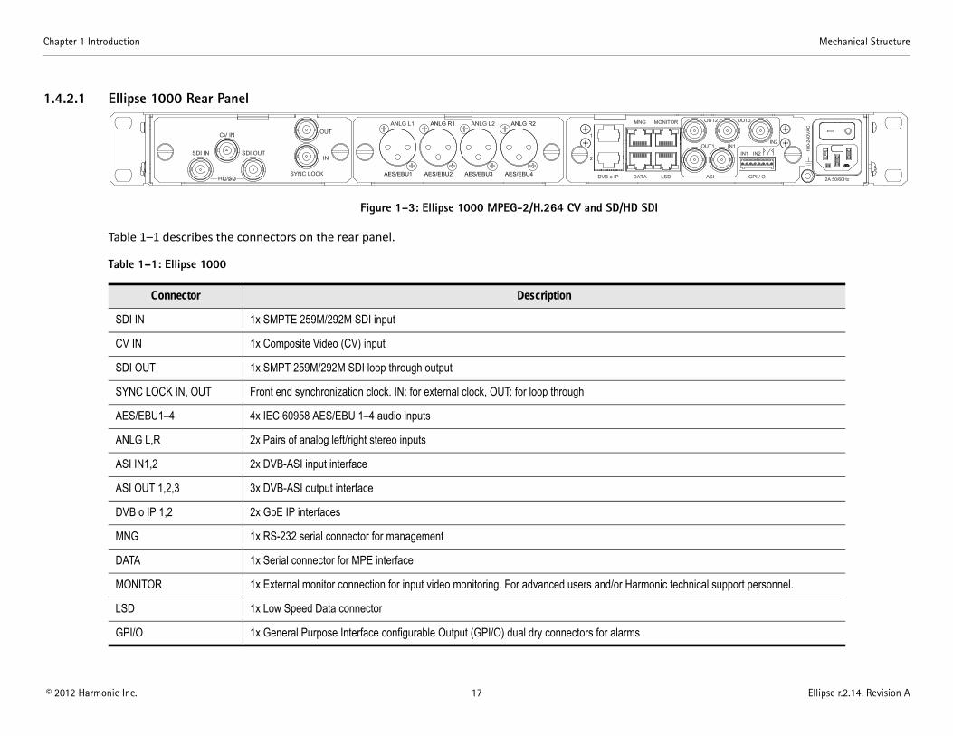
1.4.2.1 Ellipse 1000 Rear Panel
Figure 1–3: Ellipse 1000 MPEG-2/H.264 CV and SD/HD SDI
Table 1–1 describes the connectors on the rear panel.
Table 1–1: Ellipse 1000
Connector Description
SDI IN 1x SMPTE 259M/292M SDI input
CV IN 1x Composite Video (CV) input
SDI OUT 1x SMPT 259M/292M SDI loop through output
SYNC LOCK IN, OUT Front end synchronization clock. IN: for external clock, OUT: for loop through
AES/EBU1–4 4x IEC 60958 AES/EBU 1–4 audio inputs
ANLG L,R 2x Pairs of analog left/right stereo inputs
ASI IN1,2 2x DVB-ASI input interface
ASI OUT 1,2,3 3x DVB-ASI output interface
DVB o IP 1,2 2x GbE IP interfaces
MNG 1x RS-232 serial connector for management
DATA 1x Serial connector for MPE interface
MONITOR 1x External monitor connection for input video monitoring. For advanced users and/or Harmonic technical support personnel.
LSD 1x Low Speed Data connector
GPI/O 1x General Purpose Interface configurable Output (GPI/O) dual dry connectors for alarms
Chapter 1 Introduction Mechanical Structure
© 2012 Harmonic Inc. 18 Ellipse r.2.14, Revision A
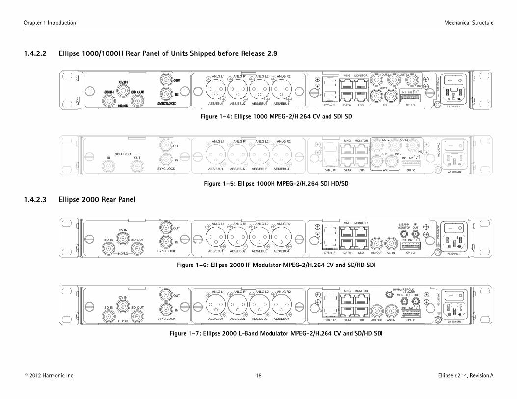
1.4.2.2 Ellipse 1000/1000H Rear Panel of Units Shipped before Release 2.9
Figure 1–4: Ellipse 1000 MPEG-2/H.264 CV and SDI SD
Figure 1–5: Ellipse 1000H MPEG-2/H.264 SDI HD/SD
1.4.2.3 Ellipse 2000 Rear Panel
Figure 1–6: Ellipse 2000 IF Modulator MPEG-2/H.264 CV and SD/HD SDI
Figure 1–7: Ellipse 2000 L-Band Modulator MPEG-2/H.264 CV and SD/HD SDI
Chapter 1 Introduction Mechanical Structure
© 2012 Harmonic Inc. 19 Ellipse r.2.14, Revision A
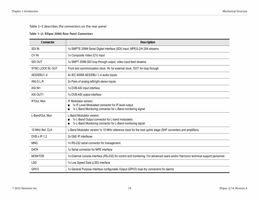
Table 1–2 describes the connectors on the rear panel
Table 1–2: Ellipse 2000 Rear Panel Connectors
Connector Description
SDI IN 1x SMPTE 259M Serial Digital Interface (SDI) input, MPEG-2/H.264 streams
CV IN 1x Composite Video (CV) input
SDI OUT 1x SMPT 259M SDI loop through output, video input feed streams
SYNC LOCK IN, OUT Front end synchronization clock. IN: for external clock, OUT: for loop through
AES/EBU1–4 4x IEC 60958 AES/EBU 1–4 audio inputs
ANLG L,R 2x Pairs of analog left/right stereo inputs
ASI IN1 1x DVB-ASI input interface
ASI OUT1 1x DVB-ASI output interface
IF/Out, Mon IF Modulator version: 1x IF Level Modulated connector for IF-level output 1x L-Band Monitoring connector for L-Band monitoring signal
L-Band/Out, Mon L-Band Modulator version: 1x L-Band Output connector for L-band modulated. 1x L-Band Monitoring connector for L-Band monitoring signal.
10 MHz Ref. CLK L-Band Modulator version:1x 10 MHz reference clock for the next uplink stage (SHF converters and amplifiers)
DVB o IP 1,2 2x GbE IP interfaces
MNG 1x RS-232 serial connector for management
DATA 1x Serial connector for MPE interface
MONITOR 1x External console interface (RS-232) for control and monitoring. For advanced users and/or Harmonic technical support personnel.
LSD 1x Low Speed Data (LSD) interface
GPI/O 1x General Purpose Interface configurable Output (GPI/O) dual dry connectors for alarms
Chapter 1 Introduction Mechanical Structure
© 2012 Harmonic Inc. 20 Ellipse r.2.14, Revision A
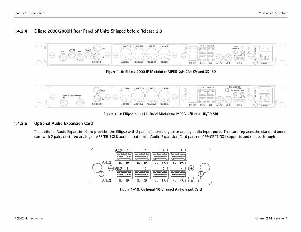
1.4.2.4 Ellipse 2000/2000H Rear Panel of Units Shipped before Release 2.9
Figure 1–8: Ellipse 2000 IF Modulator MPEG-2/H.264 CV and SDI SD
Figure 1–9: Ellipse 2000H L-Band Modulator MPEG-2/H.264 HD/SD SDI
1.4.2.5 Optional Audio Expansion Card
The optional Audio Expansion Card provides the Ellipse with 8 pairs of stereo digital or analog audio input ports. This card replaces the standard audio card with 2 pairs of stereo analog or AES/EBU XLR audio input ports. Audio Expansion Card part no. 099-0547-001 supports audio pass through.
Figure 1–10: Optional 16 Channel Audio Input Card
© 2012 Harmonic Inc. 21 Ellipse r.2.14, Revision A
Chapter 2Initial Configuration and Basic Operation
This chapter provides detailed instructions for initialization and basic configuration in order to activate the encoder.
It also provides step-by-step procedures for some of the more frequent set-up, configuration and management activities required from the Ellipse operators.
Topics: Web Configuration
Ellipse Set-Up Procedures
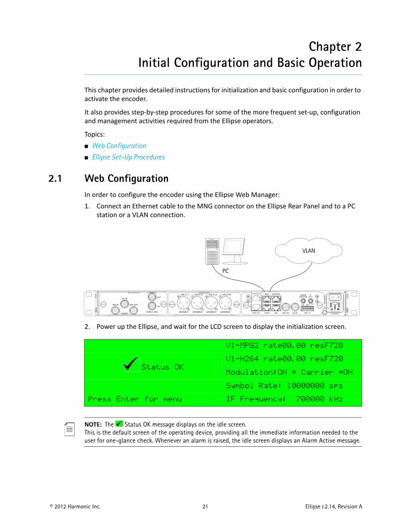
2.1 Web ConfigurationIn order to configure the encoder using the Ellipse Web Manager:1. Connect an Ethernet cable to the MNG connector on the Ellipse Rear Panel and to a PC
station or a VLAN connection.
2. Power up the Ellipse, and wait for the LCD screen to display the initialization screen.
NOTE: The Status OK message displays on the idle screen. This is the default screen of the operating device, providing all the immediate information needed to the user for one-glance check. Whenever an alarm is raised, the idle screen displays an Alarm Active message.
V1-MPG2 rate00.00 resF720
Status OK
V1-H264 rate00.00 resF720
Modulation:ON * Carrier *ON
Symbol Rate: 10000000 sps
Press Enter for menu IF Frequency: 700000 kHz
VLAN
PC
Chapter 2 Initial Configuration and Basic Operation Web Configuration
© 2012 Harmonic Inc. 22 Ellipse r.2.14, Revision A
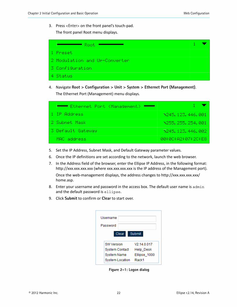
3. Press <Enter> on the front panel’s touch-pad.The front panel Root menu displays.
4. Navigate Root > Configuration > Unit > System > Ethernet Port (Management).The Ethernet Port (Management) menu displays.
5. Set the IP Address, Subnet Mask, and Default Gateway parameter values.6. Once the IP definitions are set according to the network, launch the web browser.7. In the Address field of the browser, enter the Ellipse IP Address, in the following format:
http://xxx.xxx.xxx.xxx (where xxx.xxx.xxx.xxx is the IP address of the Management port).Once the web-management displays, the address changes to http://xxx.xxx.xxx.xxx/home.asp.
8. Enter your username and password in the access box. The default user name is admin and the default password is ellipse.
9. Click Submit to confirm or Clear to start over.
Figure 2–1: Logon dialog
Root 1
1 Preset
2 Modulation and Up-Converter
3 Configuration
4 Status
Ethernet Port (Management) 1
1 IP Address 245.123.446.001
2 Subnet Mask 255.255.254.001
3 Default Gateway 245.123.446.002
MAC address 00:0C:A2:07:2C:E8
Chapter 2 Initial Configuration and Basic Operation Web Configuration
© 2012 Harmonic Inc. 23 Ellipse r.2.14, Revision A
Once initialization is complete and the web manager displays, you can set up the system. For details on web manager operations, see Ellipse Management.
NOTE: When accessed from remote using the web, there is a print: “remote http connection”. If there are several simultaneously http connections, there is a print: “multiple http connection”.
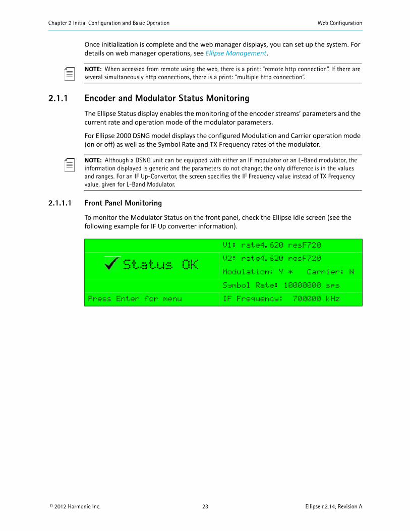
2.1.1 Encoder and Modulator Status Monitoring
The Ellipse Status display enables the monitoring of the encoder streams’ parameters and the current rate and operation mode of the modulator parameters.
For Ellipse 2000 DSNG model displays the configured Modulation and Carrier operation mode (on or off) as well as the Symbol Rate and TX Frequency rates of the modulator.
NOTE: Although a DSNG unit can be equipped with either an IF modulator or an L-Band modulator, the information displayed is generic and the parameters do not change; the only difference is in the values and ranges. For an IF Up-Convertor, the screen specifies the IF Frequency value instead of TX Frequency value, given for L-Band Modulator.
2.1.1.1 Front Panel Monitoring
To monitor the Modulator Status on the front panel, check the Ellipse Idle screen (see the following example for IF Up converter information).
V1: rate4.620 resF720
Status OKV2: rate4.620 resF720
Modulation: Y * Carrier: N
Symbol Rate: 10000000 sps
Press Enter for menu IF Frequency: 700000 kHz
Chapter 2 Initial Configuration and Basic Operation Web Configuration
© 2012 Harmonic Inc. 24 Ellipse r.2.14, Revision A
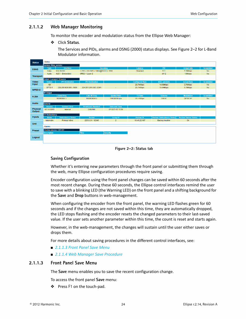
2.1.1.2 Web Manager Monitoring
To monitor the encoder and modulation status from the Ellipse Web Manager: Click Status.
The Services and PIDs, alarms and DSNG (2000) status displays. See Figure 2–2 for L-Band Modulator information.
Figure 2–2: Status tab
Saving Configuration
Whether it’s entering new parameters through the front panel or submitting them through the web, many Ellipse configuration procedures require saving.
Encoder configuration using the front panel changes can be saved within 60 seconds after the most recent change. During these 60 seconds, the Ellipse control interfaces remind the user to save with a blinking LED (the Warning LED) on the front panel and a shifting background for the Save and Drop buttons in web-management.
When configuring the encoder from the front panel, the warning LED flashes green for 60 seconds and if the changes are not saved within this time, they are automatically dropped, the LED stops flashing and the encoder resets the changed parameters to their last-saved value. If the user sets another parameter within this time, the count is reset and starts again.
However, in the web-management, the changes will sustain until the user either saves or drops them.
For more details about saving procedures in the different control interfaces, see: 2.1.1.3 Front Panel Save Menu 2.1.1.4 Web Manager Save Procedure
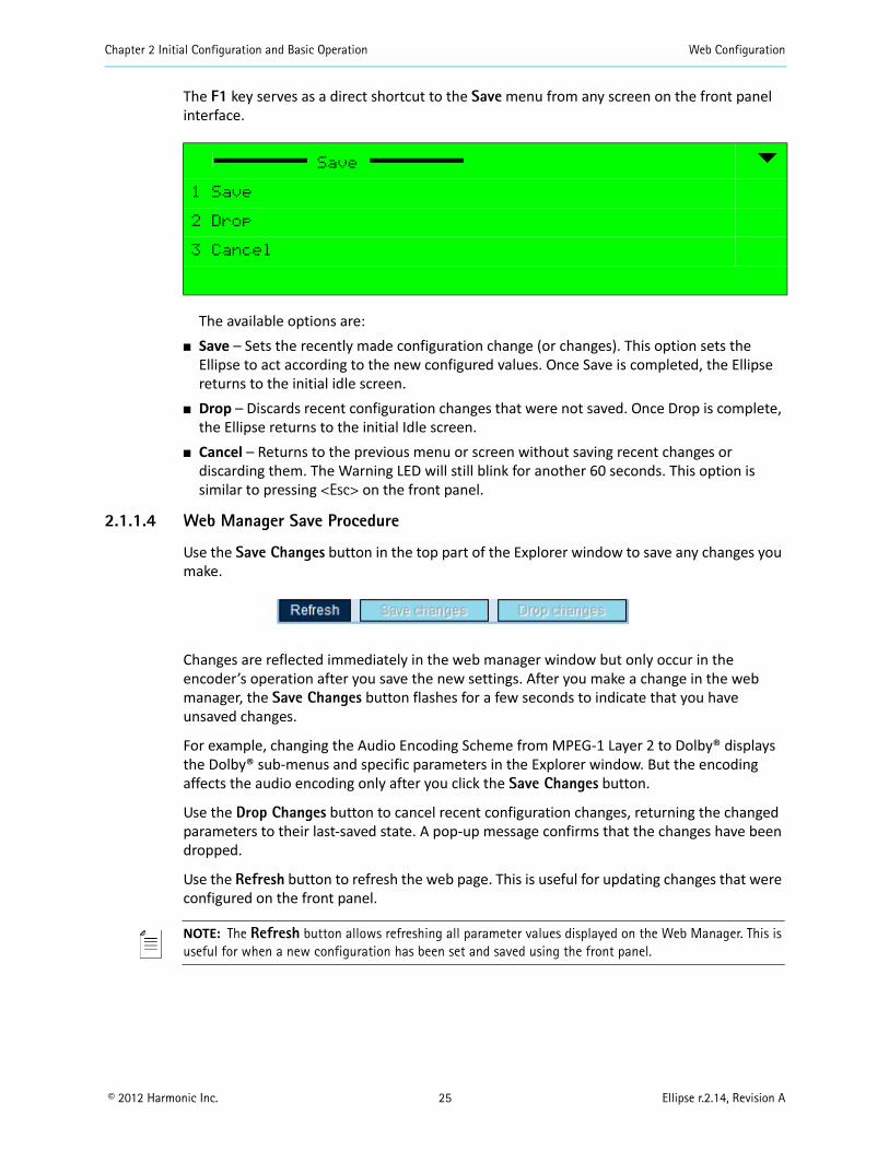
2.1.1.3 Front Panel Save Menu
The Save menu enables you to save the recent configuration change.
To access the front panel Save menu: Press F1 on the touch-pad.
Chapter 2 Initial Configuration and Basic Operation Web Configuration
© 2012 Harmonic Inc. 25 Ellipse r.2.14, Revision A
The F1 key serves as a direct shortcut to the Save menu from any screen on the front panel interface.
The available options are: Save – Sets the recently made configuration change (or changes). This option sets the
Ellipse to act according to the new configured values. Once Save is completed, the Ellipse returns to the initial idle screen.
Drop – Discards recent configuration changes that were not saved. Once Drop is complete, the Ellipse returns to the initial Idle screen.
Cancel – Returns to the previous menu or screen without saving recent changes or discarding them. The Warning LED will still blink for another 60 seconds. This option is similar to pressing <Esc> on the front panel.
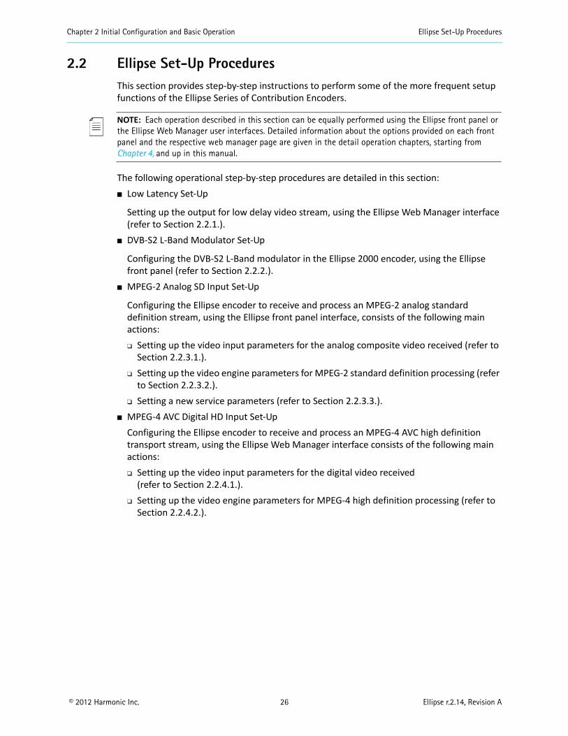
2.1.1.4 Web Manager Save Procedure
Use the Save Changes button in the top part of the Explorer window to save any changes you make.
Changes are reflected immediately in the web manager window but only occur in the encoder’s operation after you save the new settings. After you make a change in the web manager, the Save Changes button flashes for a few seconds to indicate that you have unsaved changes.
For example, changing the Audio Encoding Scheme from MPEG-1 Layer 2 to Dolby® displays the Dolby® sub-menus and specific parameters in the Explorer window. But the encoding affects the audio encoding only after you click the Save Changes button.
Use the Drop Changes button to cancel recent configuration changes, returning the changed parameters to their last-saved state. A pop-up message confirms that the changes have been dropped.
Use the Refresh button to refresh the web page. This is useful for updating changes that were configured on the front panel.
NOTE: The Refresh button allows refreshing all parameter values displayed on the Web Manager. This is useful for when a new configuration has been set and saved using the front panel.
Save
1 Save
2 Drop
3 Cancel
Chapter 2 Initial Configuration and Basic Operation Ellipse Set-Up Procedures
© 2012 Harmonic Inc. 26 Ellipse r.2.14, Revision A
2.2 Ellipse Set-Up ProceduresThis section provides step-by-step instructions to perform some of the more frequent setup functions of the Ellipse Series of Contribution Encoders.
NOTE: Each operation described in this section can be equally performed using the Ellipse front panel or the Ellipse Web Manager user interfaces. Detailed information about the options provided on each front panel and the respective web manager page are given in the detail operation chapters, starting from Chapter 4, and up in this manual.
The following operational step-by-step procedures are detailed in this section: Low Latency Set-Up
Setting up the output for low delay video stream, using the Ellipse Web Manager interface (refer to Section 2.2.1.).
DVB-S2 L-Band Modulator Set-Up
Configuring the DVB-S2 L-Band modulator in the Ellipse 2000 encoder, using the Ellipse front panel (refer to Section 2.2.2.).
MPEG-2 Analog SD Input Set-Up
Configuring the Ellipse encoder to receive and process an MPEG-2 analog standard definition stream, using the Ellipse front panel interface, consists of the following main actions: Setting up the video input parameters for the analog composite video received (refer to
Section 2.2.3.1.). Setting up the video engine parameters for MPEG-2 standard definition processing (refer
to Section 2.2.3.2.). Setting a new service parameters (refer to Section 2.2.3.3.).
MPEG-4 AVC Digital HD Input Set-UpConfiguring the Ellipse encoder to receive and process an MPEG-4 AVC high definition transport stream, using the Ellipse Web Manager interface consists of the following main actions: Setting up the video input parameters for the digital video received
(refer to Section 2.2.4.1.). Setting up the video engine parameters for MPEG-4 high definition processing (refer to
Section 2.2.4.2.).
Chapter 2 Initial Configuration and Basic Operation Ellipse Set-Up Procedures
© 2012 Harmonic Inc. 27 Ellipse r.2.14, Revision A
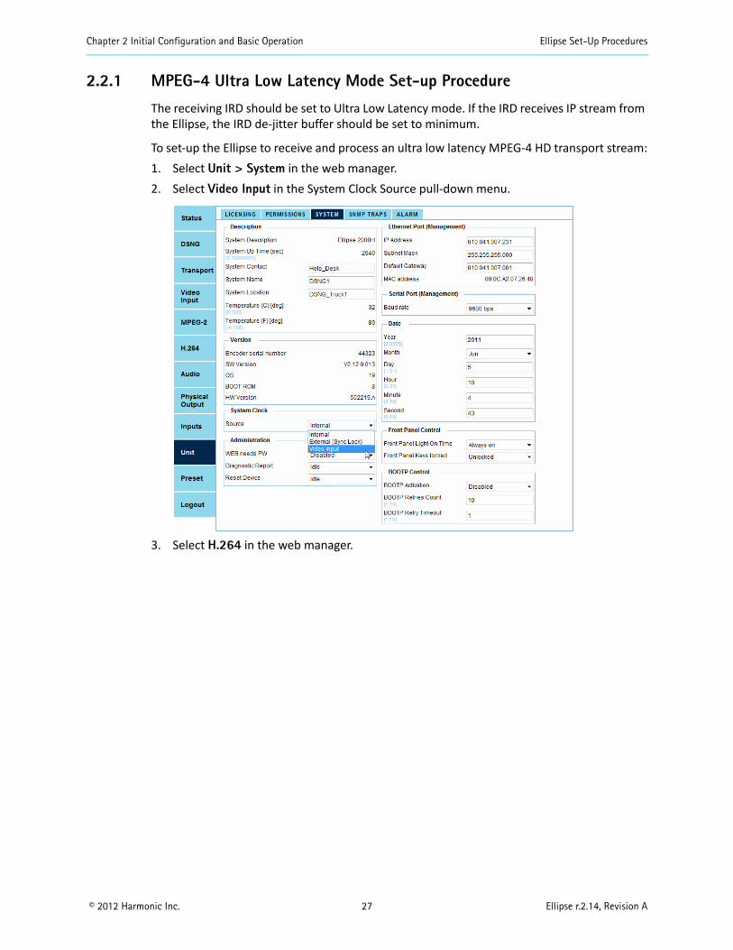
2.2.1 MPEG-4 Ultra Low Latency Mode Set-up Procedure
The receiving IRD should be set to Ultra Low Latency mode. If the IRD receives IP stream from the Ellipse, the IRD de-jitter buffer should be set to minimum.
To set-up the Ellipse to receive and process an ultra low latency MPEG-4 HD transport stream:1. Select Unit > System in the web manager.2. Select Video Input in the System Clock Source pull-down menu.
3. Select H.264 in the web manager.

Chapter 2 Initial Configuration and Basic Operation Ellipse Set-Up Procedures
© 2012 Harmonic Inc. 28 Ellipse r.2.14, Revision A
4. Select Ultra Low in the Latency Control pull-down menu.
NOTE: When using a DVB-S L-Band modulator, the frame length is user selectable. The 16,200 bits option should be set for the Ultra Low latency mode.
5. Select DSNG in the web manager.6. Select 16,200 bits in the Frame Length pull-down menu.
7. Click Save changes to save the Ultra Low latency configuration (refer to 2.1.1.4 Web Manager Save Procedure for configuration save instructions).
Chapter 2 Initial Configuration and Basic Operation Ellipse Set-Up Procedures
© 2012 Harmonic Inc. 29 Ellipse r.2.14, Revision A
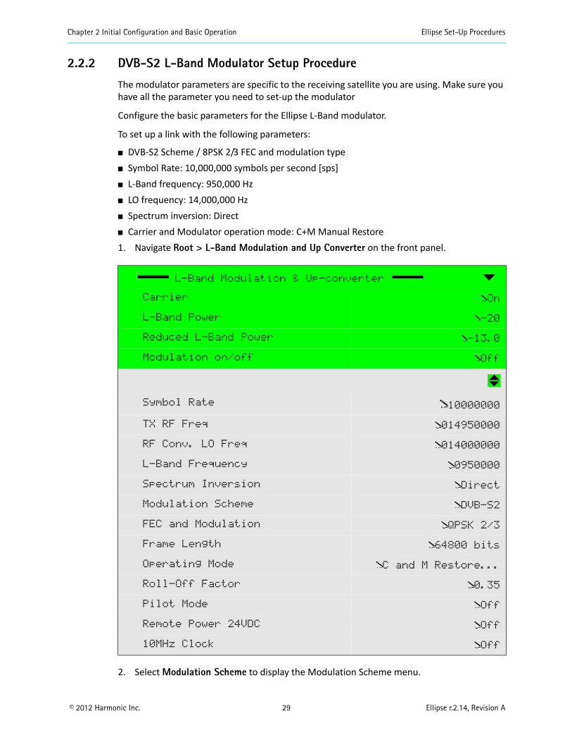
2.2.2 DVB-S2 L-Band Modulator Setup Procedure
The modulator parameters are specific to the receiving satellite you are using. Make sure you have all the parameter you need to set-up the modulator
Configure the basic parameters for the Ellipse L-Band modulator.
To set up a link with the following parameters:
DVB-S2 Scheme / 8PSK 2/3 FEC and modulation type Symbol Rate: 10,000,000 symbols per second [sps] L-Band frequency: 950,000 Hz LO frequency: 14,000,000 Hz Spectrum inversion: Direct Carrier and Modulator operation mode: C+M Manual Restore1. Navigate Root > L-Band Modulation and Up Converter on the front panel.
2. Select Modulation Scheme to display the Modulation Scheme menu.
L-Band Modulation & Up-converter
Carrier On
L-Band Power -20
Reduced L-Band Power -13.0
Modulation on/off Off
Symbol Rate 10000000
TX RF Freq 014950000
RF Conv. LO Freq 014000000
L-Band Frequency 0950000
Spectrum Inversion Direct
Modulation Scheme DVB-S2
FEC and Modulation QPSK 2/3
Frame Length 64800 bits
Operating Mode C and M Restore...
Roll-Off Factor 0.35
Pilot Mode Off
Remote Power 24VDC Off
10MHz Clock Off
Chapter 2 Initial Configuration and Basic Operation Ellipse Set-Up Procedures
© 2012 Harmonic Inc. 30 Ellipse r.2.14, Revision A
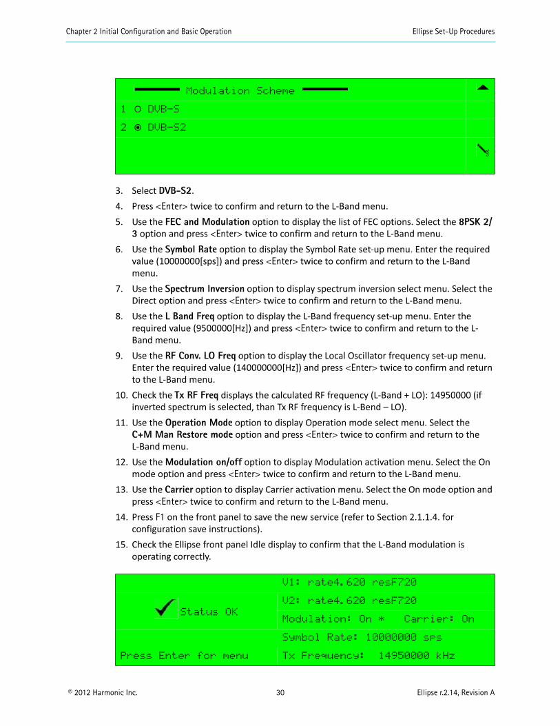
3. Select DVB-S2.4. Press <Enter> twice to confirm and return to the L-Band menu.5. Use the FEC and Modulation option to display the list of FEC options. Select the 8PSK 2/
3 option and press <Enter> twice to confirm and return to the L-Band menu.6. Use the Symbol Rate option to display the Symbol Rate set-up menu. Enter the required
value (10000000[sps]) and press <Enter> twice to confirm and return to the L-Band menu.
7. Use the Spectrum Inversion option to display spectrum inversion select menu. Select the Direct option and press <Enter> twice to confirm and return to the L-Band menu.
8. Use the L Band Freq option to display the L-Band frequency set-up menu. Enter the required value (9500000[Hz]) and press <Enter> twice to confirm and return to the L-Band menu.
9. Use the RF Conv. LO Freq option to display the Local Oscillator frequency set-up menu. Enter the required value (140000000[Hz]) and press <Enter> twice to confirm and return to the L-Band menu.
10. Check the Tx RF Freq displays the calculated RF frequency (L-Band + LO): 14950000 (if inverted spectrum is selected, than Tx RF frequency is L-Bend – LO).
11. Use the Operation Mode option to display Operation mode select menu. Select the C+M Man Restore mode option and press <Enter> twice to confirm and return to the L-Band menu.
12. Use the Modulation on/off option to display Modulation activation menu. Select the On mode option and press <Enter> twice to confirm and return to the L-Band menu.
13. Use the Carrier option to display Carrier activation menu. Select the On mode option and press <Enter> twice to confirm and return to the L-Band menu.
14. Press F1 on the front panel to save the new service (refer to Section 2.1.1.4. for configuration save instructions).
15. Check the Ellipse front panel Idle display to confirm that the L-Band modulation is operating correctly.
Modulation Scheme
1 ‚ DVB-S
2 ƒ DVB-S2
V1: rate4.620 resF720
Status OK
V2: rate4.620 resF720
Modulation: On * Carrier: On
Symbol Rate: 10000000 sps
Press Enter for menu Tx Frequency: 14950000 kHz
Chapter 2 Initial Configuration and Basic Operation Ellipse Set-Up Procedures
© 2012 Harmonic Inc. 31 Ellipse r.2.14, Revision A
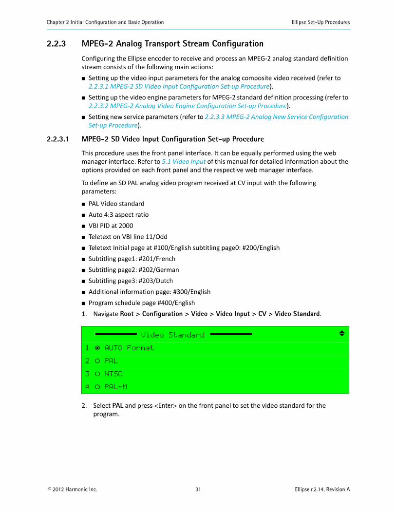
2.2.3 MPEG-2 Analog Transport Stream Configuration
Configuring the Ellipse encoder to receive and process an MPEG-2 analog standard definition stream consists of the following main actions: Setting up the video input parameters for the analog composite video received (refer to
2.2.3.1 MPEG-2 SD Video Input Configuration Set-up Procedure). Setting up the video engine parameters for MPEG-2 standard definition processing (refer to
2.2.3.2 MPEG-2 Analog Video Engine Configuration Set-up Procedure). Setting new service parameters (refer to 2.2.3.3 MPEG-2 Analog New Service Configuration
Set-up Procedure).
2.2.3.1 MPEG-2 SD Video Input Configuration Set-up Procedure
This procedure uses the front panel interface. It can be equally performed using the web manager interface. Refer to 5.1 Video Input of this manual for detailed information about the options provided on each front panel and the respective web manager interface.
To define an SD PAL analog video program received at CV input with the following parameters:
PAL Video standard Auto 4:3 aspect ratio VBI PID at 2000 Teletext on VBI line 11/Odd Teletext Initial page at #100/English subtitling page0: #200/English Subtitling page1: #201/French Subtitling page2: #202/German Subtitling page3: #203/Dutch Additional information page: #300/English Program schedule page #400/English1. Navigate Root > Configuration > Video > Video Input > CV > Video Standard.
2. Select PAL and press <Enter> on the front panel to set the video standard for the program.
Video Standard
1 ƒ AUTO Format
2 ‚ PAL
3 ‚ NTSC
4 ‚ PAL-M
Chapter 2 Initial Configuration and Basic Operation Ellipse Set-Up Procedures
© 2012 Harmonic Inc. 32 Ellipse r.2.14, Revision A
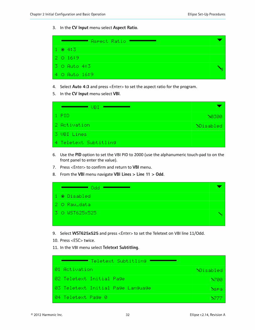
3. In the CV Input menu select Aspect Ratio.
4. Select Auto 4:3 and press <Enter> to set the aspect ratio for the program.5. In the CV Input menu select VBI.
6. Use the PID option to set the VBI PID to 2000 (use the alphanumeric touch-pad to on the front panel to enter the value).
7. Press <Enter> to confirm and return to VBI menu.8. From the VBI menu navigate VBI Lines > Line 11 > Odd.
9. Select WST625x525 and press <Enter> to set the Teletext on VBI line 11/Odd.10. Press <ESC> twice.11. In the VBI menu select Teletext Subtitling.
Aspect Ratio
1 ƒ 4:3
2 ‚ 16:9
3 ‚ Auto 4:3
4 ‚ Auto 16:9
VBI
1 PID 0300
2 Activation Disabled
3 VBI Lines
4 Teletext Subtitling
Odd
1 ƒ Disabled
2 ‚ Raw_data
3 ‚ WST625x525
Teletext Subtitling
01 Activation Disabled
02 Teletext Initial Page 700
03 Teletext Initial Page Language spa
04 Teletext Page 0 777
Chapter 2 Initial Configuration and Basic Operation Ellipse Set-Up Procedures
© 2012 Harmonic Inc. 33 Ellipse r.2.14, Revision A
12. Use the Teletext Initial Page option to set the page number to 100 (use the alphanumeric touch-pad to page number).
13. Press <Enter> to confirm and return to the Teletext Subtitling menu.14. Use the Teletext Initial Language option to set the language.15. Press <Enter> to confirm and return to the Teletext Subtitling menu.16. Select Activation to enable the teletext subtitling activation.17. Press <ESC>, and <ESC> a second time to return to the VBI menu.18. Press F1 on the front panel to save the new service (refer to Section 2.1.1.3. for
configuration save instructions).
2.2.3.2 MPEG-2 Analog Video Engine Configuration Set-up Procedure
This procedure uses the front panel interface. It can be equally performed using the web manager interface. Refer to section 5.2 Video Engine of this manual for detailed information about the options provided on each front panel and the respective web manager interface.
All parameters not set in the procedure should be set to their default values (video resolution set to automatic; channel maximum rate at 4.5 Mbps and latency control at normal).
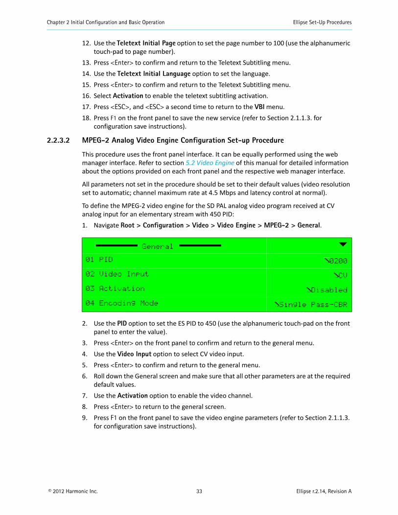
To define the MPEG-2 video engine for the SD PAL analog video program received at CV analog input for an elementary stream with 450 PID: 1. Navigate Root > Configuration > Video > Video Engine > MPEG-2 > General.
2. Use the PID option to set the ES PID to 450 (use the alphanumeric touch-pad on the front panel to enter the value).
3. Press <Enter> on the front panel to confirm and return to the general menu.4. Use the Video Input option to select CV video input.5. Press <Enter> to confirm and return to the general menu.6. Roll down the General screen and make sure that all other parameters are at the required
default values.7. Use the Activation option to enable the video channel.8. Press <Enter> to return to the general screen.9. Press F1 on the front panel to save the video engine parameters (refer to Section 2.1.1.3.
for configuration save instructions).
General
01 PID 0200
02 Video Input CV
03 Activation Disabled
04 Encoding Mode Single Pass-CBR
Chapter 2 Initial Configuration and Basic Operation Ellipse Set-Up Procedures
© 2012 Harmonic Inc. 34 Ellipse r.2.14, Revision A
2.2.3.3 MPEG-2 Analog New Service Configuration Set-up Procedure
This procedure uses the front panel interface. It can be equally performed using the web manager interface. Refer to section 4.4 Services Menu of this manual for detailed information about the options provided on each front panel and the respective web manager interface.
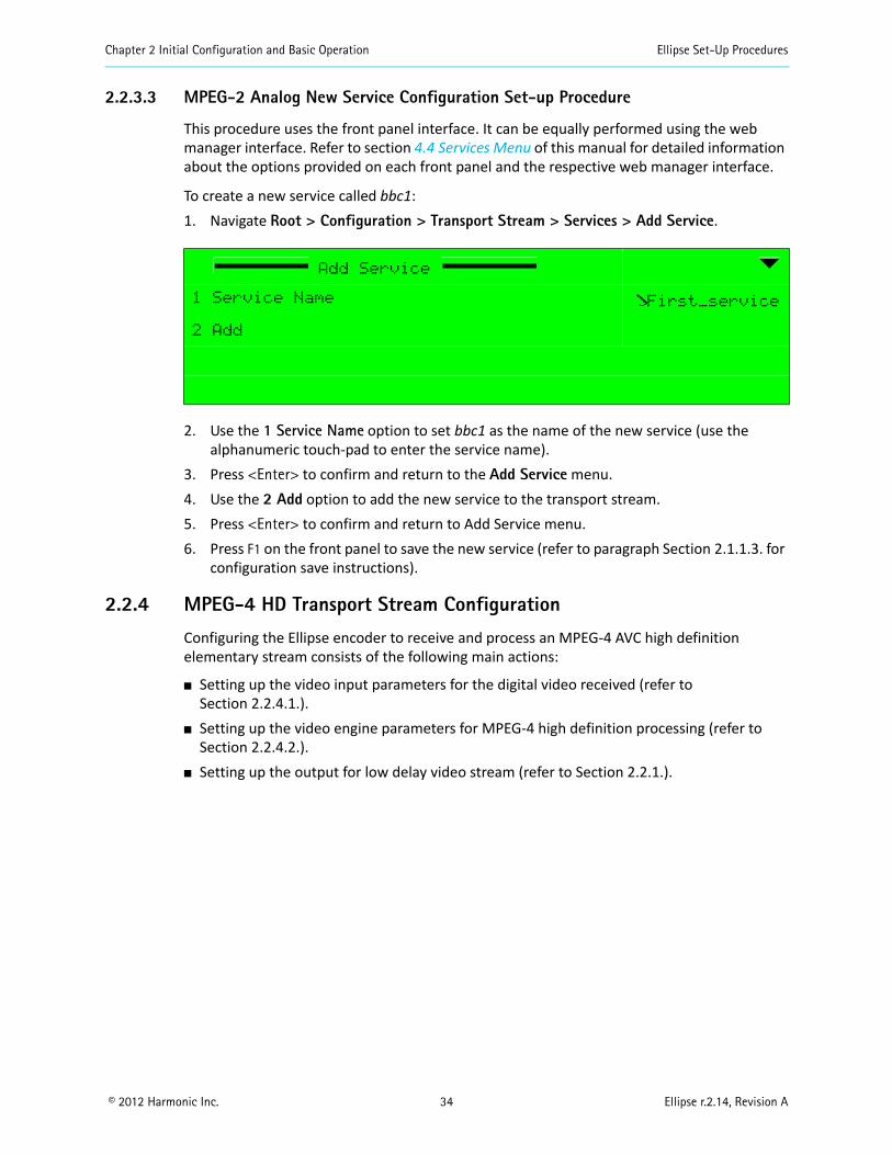
To create a new service called bbc1:1. Navigate Root > Configuration > Transport Stream > Services > Add Service.
2. Use the 1 Service Name option to set bbc1 as the name of the new service (use the alphanumeric touch-pad to enter the service name).
3. Press <Enter> to confirm and return to the Add Service menu.4. Use the 2 Add option to add the new service to the transport stream.5. Press <Enter> to confirm and return to Add Service menu.6. Press F1 on the front panel to save the new service (refer to paragraph Section 2.1.1.3. for
configuration save instructions).
2.2.4 MPEG-4 HD Transport Stream Configuration
Configuring the Ellipse encoder to receive and process an MPEG-4 AVC high definition elementary stream consists of the following main actions:
Setting up the video input parameters for the digital video received (refer to Section 2.2.4.1.).
Setting up the video engine parameters for MPEG-4 high definition processing (refer to Section 2.2.4.2.).
Setting up the output for low delay video stream (refer to Section 2.2.1.).
Add Service
1 Service Name First_service
2 Add
Chapter 2 Initial Configuration and Basic Operation Ellipse Set-Up Procedures
© 2012 Harmonic Inc. 35 Ellipse r.2.14, Revision A
2.2.4.1 MPEG-4 HD Video Input Configuration Set-up Procedure
This procedure uses the web manager interface. It can be equally performed using the front panel interface. Refer to of this manual for detailed information about the options provided on the web manager interface and the respective front panel interface.
To define an HD video program received on the SD/HD-SDI input with the following parameters:
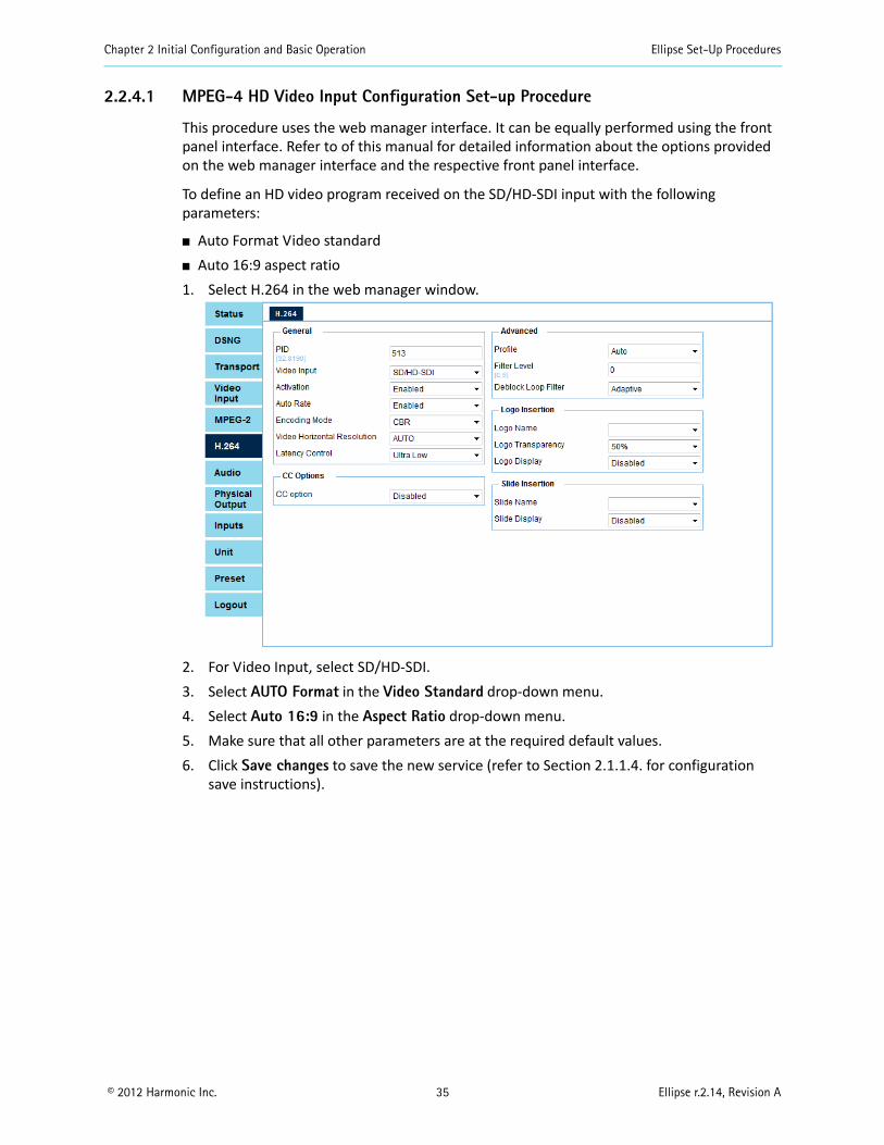
Auto Format Video standard Auto 16:9 aspect ratio1. Select H.264 in the web manager window.
2. For Video Input, select SD/HD-SDI.3. Select AUTO Format in the Video Standard drop-down menu.4. Select Auto 16:9 in the Aspect Ratio drop-down menu.5. Make sure that all other parameters are at the required default values.6. Click Save changes to save the new service (refer to Section 2.1.1.4. for configuration
save instructions).
Chapter 2 Initial Configuration and Basic Operation Ellipse Set-Up Procedures
© 2012 Harmonic Inc. 36 Ellipse r.2.14, Revision A
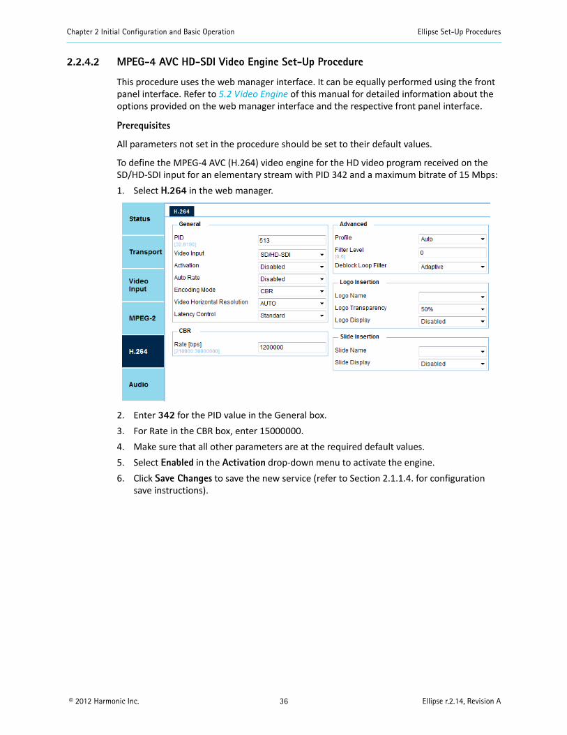
2.2.4.2 MPEG-4 AVC HD-SDI Video Engine Set-Up Procedure
This procedure uses the web manager interface. It can be equally performed using the front panel interface. Refer to 5.2 Video Engine of this manual for detailed information about the options provided on the web manager interface and the respective front panel interface.
Prerequisites
All parameters not set in the procedure should be set to their default values.
To define the MPEG-4 AVC (H.264) video engine for the HD video program received on the SD/HD-SDI input for an elementary stream with PID 342 and a maximum bitrate of 15 Mbps:1. Select H.264 in the web manager.
2. Enter 342 for the PID value in the General box.3. For Rate in the CBR box, enter 15000000.4. Make sure that all other parameters are at the required default values.5. Select Enabled in the Activation drop-down menu to activate the engine.6. Click Save Changes to save the new service (refer to Section 2.1.1.4. for configuration
save instructions).
© 2012 Harmonic Inc. 37 Ellipse r.2.14, Revision A
Chapter 3Ellipse Management
The Ellipse front panel interface provides access to all encoder control parameters, while the Ellipse Web Manager interface allows easy access to the same parameters from a remote computer. Therefore, these two interfaces are intertwined in the description provided by this manual.
Each interface is menu structured in a root up tree structure, described in the following paragraphs and detailed in the following chapters.
Topics: Ellipse Management Interfaces
Ellipse Management Menu Tree
Preset Menu
Configuration Menu
Status Menu
3.1 Ellipse Management InterfacesThe Ellipse Series of Contribution Encoders offers the two management interfaces to the Ellipse operator: Front panel interface for local management (see 3.1.1 Ellipse Front Panel Control Interface) Web Manager interface for remote management (see 3.1.2 Ellipse Web Management
Control Interface)
3.1.1 Ellipse Front Panel Control Interface
The front panel of the Ellipse provides extensive local control abilities along with convenient monitoring of statuses and operations.
The section is divided as follows: Front Panel Controls and Displays – Details the front panel touchpad keys and their
functions. Front Panel Screen Types – Details the LCD screen’s different displays. The Ellipse front panel features lockup and sleep modes:
Front panel Lockup Mode enables locking the encoder from unintentional activation of the front panel.
Backup Light Sleep Mode enables power saving when the encoder is not locally operated.
Chapter 3 Ellipse Management Ellipse Management Interfaces
© 2012 Harmonic Inc. 38 Ellipse r.2.14, Revision A
3.1.1.1 Front Panel Controls and Displays
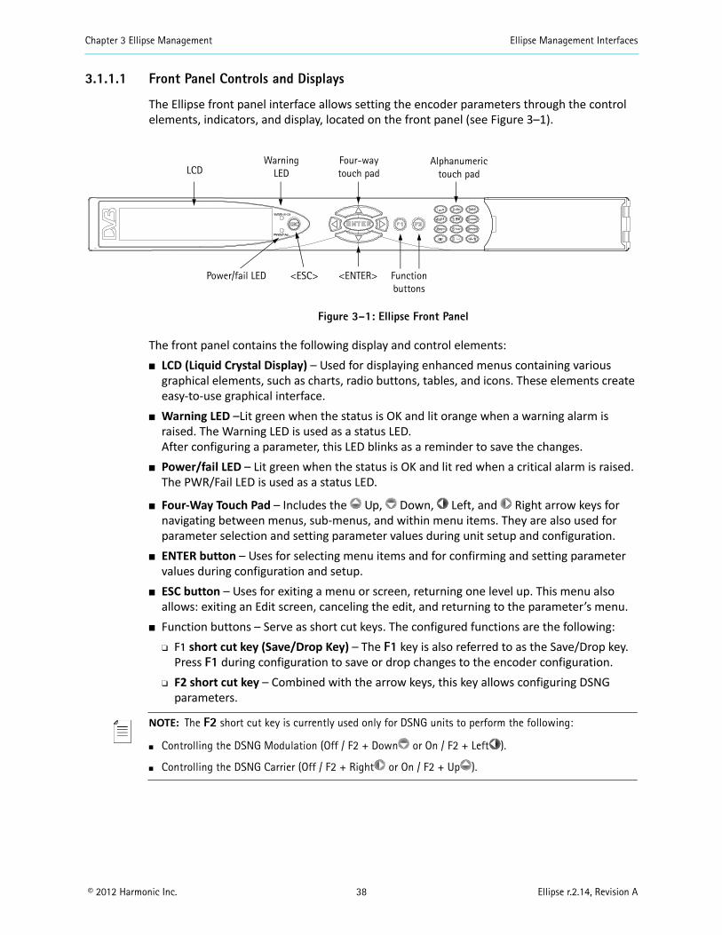
The Ellipse front panel interface allows setting the encoder parameters through the control elements, indicators, and display, located on the front panel (see Figure 3–1).
Figure 3–1: Ellipse Front Panel
The front panel contains the following display and control elements: LCD (Liquid Crystal Display) – Used for displaying enhanced menus containing various
graphical elements, such as charts, radio buttons, tables, and icons. These elements create easy-to-use graphical interface.
Warning LED –Lit green when the status is OK and lit orange when a warning alarm is raised. The Warning LED is used as a status LED. After configuring a parameter, this LED blinks as a reminder to save the changes.
Power/fail LED – Lit green when the status is OK and lit red when a critical alarm is raised. The PWR/Fail LED is used as a status LED.
Four-Way Touch Pad – Includes the Up, Down, Left, and Right arrow keys for navigating between menus, sub-menus, and within menu items. They are also used for parameter selection and setting parameter values during unit setup and configuration.
ENTER button – Uses for selecting menu items and for confirming and setting parameter values during configuration and setup.
ESC button – Uses for exiting a menu or screen, returning one level up. This menu also allows: exiting an Edit screen, canceling the edit, and returning to the parameter’s menu.
Function buttons – Serve as short cut keys. The configured functions are the following: F1 short cut key (Save/Drop Key) – The F1 key is also referred to as the Save/Drop key.
Press F1 during configuration to save or drop changes to the encoder configuration. F2 short cut key – Combined with the arrow keys, this key allows configuring DSNG
parameters.
NOTE: The F2 short cut key is currently used only for DSNG units to perform the following:
Controlling the DSNG Modulation (Off / F2 + Down or On / F2 + Left ).
Controlling the DSNG Carrier (Off / F2 + Right or On / F2 + Up ).
LCDWarning
LEDFour-way touch pad
Alphanumeric touch pad
Power/fail LED <ESC> <ENTER> Function buttons
Chapter 3 Ellipse Management Ellipse Management Interfaces
© 2012 Harmonic Inc. 39 Ellipse r.2.14, Revision A
Alphanumeric Touch Pad – Used for entering both numbers and letters, when configuring menus and parameters. 1 to 9 keys – Each alphanumeric key contains four to five different characters,
encompassing the entire English alphabet. Selecting a specific character located in a certain key is performed by repeatedly pressing the key until the relevant character is displayed.
0_ key contains two characters, zero and space. Clr key is used for clearing the contents at the cursor’s current position. +/- key is currently not supported.
A short period after a character is selected using the alphanumeric touch-pad, the cursor automatically advances to the next position on the right. Repeated presses on a single keypad insert a different character assigned to the keypad. For example, to enter the following values perform the following:
Enter the number 314:1. Press 3def once for 3.2. Press 1.,- once for 1.3. Press 4ghi once for 4.
Enter the word hello:1. Press 4ghi three times (for h).2. Press 3def three times (for e).3. Press 5jkl four times (for l).4. Wait for cursor to advance to the next position.5. Press 5jkl four times (for l again).6. Press 6mno four times (for o).
3.1.1.2 Front Panel Screen Types
The front panel uses the following five screen types:
Menu Navigation Screen – A menu comprised of other menu groups categorized according to a common parameter-setting subject (such as: video, audio, unit and so on). This menu can also contain parameters.
Edit Menu Screen – A parameter that allows managing configuration parameters and displays values of read-only parameters.
Table Menu Screen – Displays a table of information. Some tables are configurable, in which each entry selection directly links to further menus.
Edit Value Screen – Allows setting a parameter using the alphanumeric touch-pad. Select Value Screen – Allows the user to select a value from a list.
NOTE: The front panel can display only up to four items simultaneously. When a menu or screen has more than four items, the first four are visible on the front panel and additional items can be accessed by
scrolling (using the Up and Down arrows). To illustrate the difference between the displayed items and the scrolled items, two types of screen-shots are used in this manual: dark grey (or green) for the visible four items and light grey for the scrolled items. The two screen-shot types are separated by a scroll
icon ( ).
Chapter 3 Ellipse Management Ellipse Management Interfaces
© 2012 Harmonic Inc. 40 Ellipse r.2.14, Revision A
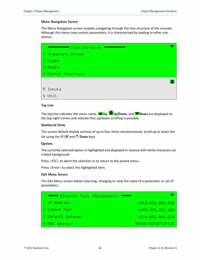
Menu Navigation Screen
The Menu Navigation screen enables navigating through the tree structure of the encoder. Although this menu may contain parameters, it is characterized by leading to other sub-menus:
Top Line
The top line indicates the menu name. Up, Up/Down, and Down are displayed on the top-right corner and indicate that up/down scrolling is possible.
Numbered Items
The screen default display consists of up to four items simultaneously. Scroll up or down the list using the UP and Down keys.
Options
The currently selected option is highlighted and displayed in reverse with white characters on a black background.
Press <ESC> to abort the selection or to return to the parent menu.
Press <Enter> to select the highlighted item.
Edit Menu Screen
The Edit Menu screen allows selecting, changing or view the value of a parameter, or set of parameters:
Configuration
1 Transport Stream
2 Video
3 Audio
4 Output Interface
5 Inputs
6 Unit
Ethernet Port (Management)
1 IP Address 010.002.002.020
2 Subnet Mask 255.255.252.000
3 Default Gateway 010.002.002.020
4 MAC address 00:0C:A2:07:2F:2C
Chapter 3 Ellipse Management Ellipse Management Interfaces
© 2012 Harmonic Inc. 41 Ellipse r.2.14, Revision A
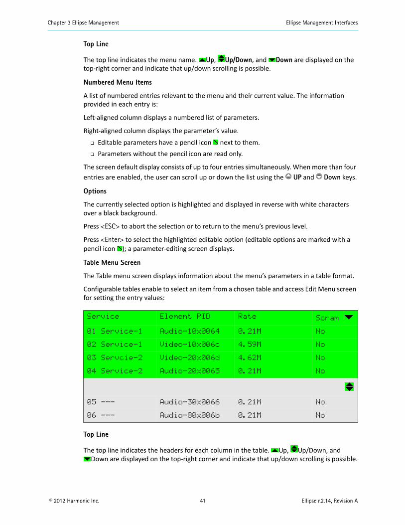
Top Line
The top line indicates the menu name. Up, Up/Down, and Down are displayed on the top-right corner and indicate that up/down scrolling is possible.
Numbered Menu Items
A list of numbered entries relevant to the menu and their current value. The information provided in each entry is:
Left-aligned column displays a numbered list of parameters.
Right-aligned column displays the parameter’s value.
Editable parameters have a pencil icon next to them. Parameters without the pencil icon are read only.
The screen default display consists of up to four entries simultaneously. When more than four entries are enabled, the user can scroll up or down the list using the UP and Down keys.
Options
The currently selected option is highlighted and displayed in reverse with white characters over a black background.
Press <ESC> to abort the selection or to return to the menu’s previous level.
Press <Enter> to select the highlighted editable option (editable options are marked with a pencil icon ); a parameter-editing screen displays.
Table Menu Screen
The Table menu screen displays information about the menu’s parameters in a table format.
Configurable tables enable to select an item from a chosen table and access Edit Menu screen for setting the entry values:
Top Line
The top line indicates the headers for each column in the table. Up, Up/Down, and Down are displayed on the top-right corner and indicate that up/down scrolling is possible.
Service Element PID Rate Scram
01 Service-1 Audio-10x0064 0.21M No
02 Service-1 Video-10x006c 4.59M No
03 Servcie-2 Video-20x006d 4.62M No
04 Service-2 Audio-20x0065 0.21M No
05 --- Audio-30x0066 0.21M No
06 --- Audio-80x006b 0.21M No
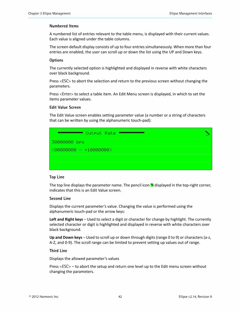
Chapter 3 Ellipse Management Ellipse Management Interfaces
© 2012 Harmonic Inc. 42 Ellipse r.2.14, Revision A
Numbered Items
A numbered list of entries relevant to the table menu, is displayed with their current values. Each value is aligned under the table columns.
The screen default display consists of up to four entries simultaneously. When more than four entries are enabled, the user can scroll up or down the list using the UP and Down keys.
Options
The currently selected option is highlighted and displayed in reverse with white characters over black background.
Press <ESC> to abort the selection and return to the previous screen without changing the parameters.
Press <Enter> to select a table item. An Edit Menu screen is displayed, in which to set the items parameter values.
Edit Value Screen
The Edit Value screen enables setting parameter value (a number or a string of characters that can be written by using the alphanumeric touch-pad):
Top Line
The top line displays the parameter name. The pencil icon displayed in the top-right corner, indicates that this is an Edit Value screen.
Second Line
Displays the current parameter’s value. Changing the value is performed using the alphanumeric touch-pad or the arrow keys:
Left and Right keys – Used to select a digit or character for change by highlight. The currently selected character or digit is highlighted and displayed in reverse with white characters over black background.
Up and Down keys – Used to scroll up or down through digits (range 0 to 9) or characters (a-z, A-Z, and 0-9). The scroll range can be limited to prevent setting up values out of range.
Third Line
Displays the allowed parameter’s values
Press <ESC> – to abort the setup and return one level up to the Edit menu screen without changing the parameters.
Output Rate
30000000 bps
<00000000 - +10000000>
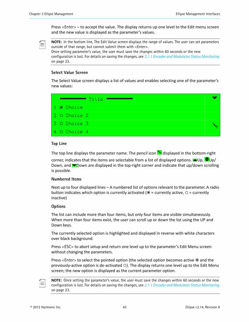
Chapter 3 Ellipse Management Ellipse Management Interfaces
© 2012 Harmonic Inc. 43 Ellipse r.2.14, Revision A
Press <Enter> – to accept the value. The display returns up one level to the Edit menu screen and the new value is displayed as the parameter’s values.
NOTE: In the bottom line, The Edit Value screen displays the range of values. The user can set parameters outside of that range, but cannot submit them with <Enter>. Once setting parameter’s value, the user must save the changes within 60 seconds or the new configuration is lost. For details on saving the changes, see 2.1.1 Encoder and Modulator Status Monitoring on page 23.
Select Value Screen
The Select Value screen displays a list of values and enables selecting one of the parameter’s new values:
Top Line
The top line displays the parameter name. The pencil icon displayed in the bottom-right corner, indicates that the items are selectable from a list of displayed options. Up, Up/Down, and Down are displayed in the top-right corner and indicate that up/down scrolling is possible.
Numbered Items
Next up to four displayed lines – A numbered list of options relevant to the parameter. A radio button indicates which option is currently activated (ƒ = currently active, = currently inactive)
Options
The list can include more than four items, but only four items are visible simultaneously. When more than four items exist, the user can scroll up or down the list using the UP and Down keys.
The currently selected option is highlighted and displayed in reverse with white characters over black background.
Press <ESC> to abort setup and return one level up to the parameter’s Edit Menu screen without changing the parameters.
Press <Enter> to select the pointed option (the selected option becomes active ƒ and the previously-active option is de-activated ). The display returns one level up to the Edit Menu screen; the new option is displayed as the current parameter option.
NOTE: Once setting the parameter’s value, the user must save the changes within 60 seconds or the new configuration is lost. For details on saving the changes, see 2.1.1 Encoder and Modulator Status Monitoring on page 23.
Title
1 ƒ Choice
2 ‚ Choice 2
3 ‚ Choice 3
4 ‚ Choice 4
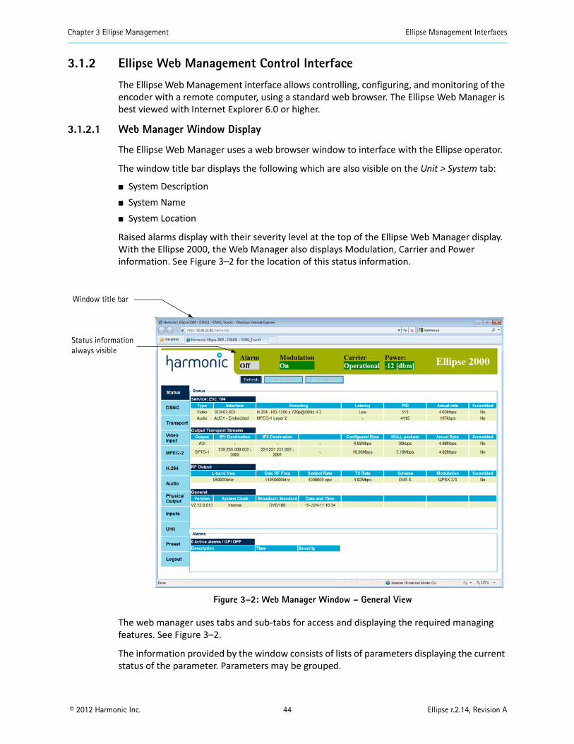
Chapter 3 Ellipse Management Ellipse Management Interfaces
© 2012 Harmonic Inc. 44 Ellipse r.2.14, Revision A
3.1.2 Ellipse Web Management Control Interface
The Ellipse Web Management interface allows controlling, configuring, and monitoring of the encoder with a remote computer, using a standard web browser. The Ellipse Web Manager is best viewed with Internet Explorer 6.0 or higher.
3.1.2.1 Web Manager Window Display
The Ellipse Web Manager uses a web browser window to interface with the Ellipse operator.
The window title bar displays the following which are also visible on the Unit > System tab:
System Description System Name System Location
Raised alarms display with their severity level at the top of the Ellipse Web Manager display. With the Ellipse 2000, the Web Manager also displays Modulation, Carrier and Power information. See Figure 3–2 for the location of this status information.
Figure 3–2: Web Manager Window – General View
The web manager uses tabs and sub-tabs for access and displaying the required managing features. See Figure 3–2.
The information provided by the window consists of lists of parameters displaying the current status of the parameter. Parameters may be grouped.
Window title bar
Status information always visible
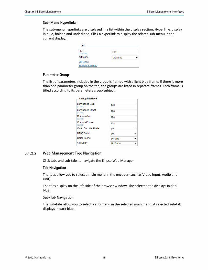
Chapter 3 Ellipse Management Ellipse Management Interfaces
© 2012 Harmonic Inc. 45 Ellipse r.2.14, Revision A
Sub-Menu Hyperlinks
The sub-menu hyperlinks are displayed in a list within the display section. Hyperlinks display in blue, bolded and underlined. Click a hyperlink to display the related sub-menu in the current display.
Parameter Group
The list of parameters included in the group is framed with a light blue frame. If there is more than one parameter group on the tab, the groups are listed in separate frames. Each frame is titled according to its parameters group subject.
3.1.2.2 Web Management Tree Navigation
Click tabs and sub-tabs to navigate the Ellipse Web Manager.
Tab Navigation
The tabs allow you to select a main menu in the encoder (such as Video Input, Audio and Unit).
The tabs display on the left side of the browser window. The selected tab displays in dark blue.
Sub-Tab Navigation
The sub-tabs allow you to select a sub-menu in the selected main menu. A selected sub-tab displays in dark blue.
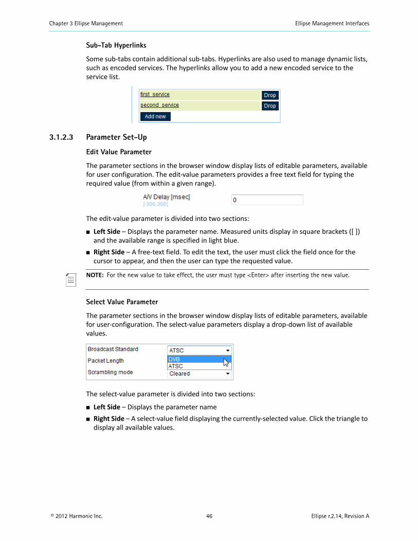
Chapter 3 Ellipse Management Ellipse Management Interfaces
© 2012 Harmonic Inc. 46 Ellipse r.2.14, Revision A
Sub-Tab Hyperlinks
Some sub-tabs contain additional sub-tabs. Hyperlinks are also used to manage dynamic lists, such as encoded services. The hyperlinks allow you to add a new encoded service to the service list.
3.1.2.3 Parameter Set-Up
Edit Value Parameter
The parameter sections in the browser window display lists of editable parameters, available for user configuration. The edit-value parameters provides a free text field for typing the required value (from within a given range).
The edit-value parameter is divided into two sections:
Left Side – Displays the parameter name. Measured units display in square brackets ([ ]) and the available range is specified in light blue.
Right Side – A free-text field. To edit the text, the user must click the field once for the cursor to appear, and then the user can type the requested value.
NOTE: For the new value to take effect, the user must type <Enter> after inserting the new value.
Select Value Parameter
The parameter sections in the browser window display lists of editable parameters, available for user-configuration. The select-value parameters display a drop-down list of available values.
The select-value parameter is divided into two sections:
Left Side – Displays the parameter name Right Side – A select-value field displaying the currently-selected value. Click the triangle to
display all available values.
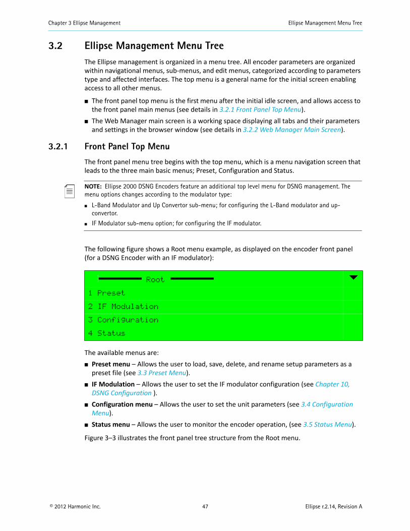
Chapter 3 Ellipse Management Ellipse Management Menu Tree
© 2012 Harmonic Inc. 47 Ellipse r.2.14, Revision A
3.2 Ellipse Management Menu TreeThe Ellipse management is organized in a menu tree. All encoder parameters are organized within navigational menus, sub-menus, and edit menus, categorized according to parameters type and affected interfaces. The top menu is a general name for the initial screen enabling access to all other menus.
The front panel top menu is the first menu after the initial idle screen, and allows access to the front panel main menus (see details in 3.2.1 Front Panel Top Menu).
The Web Manager main screen is a working space displaying all tabs and their parameters and settings in the browser window (see details in 3.2.2 Web Manager Main Screen).
3.2.1 Front Panel Top Menu
The front panel menu tree begins with the top menu, which is a menu navigation screen that leads to the three main basic menus; Preset, Configuration and Status.
NOTE: Ellipse 2000 DSNG Encoders feature an additional top level menu for DSNG management. The menu options changes according to the modulator type:
L-Band Modulator and Up Convertor sub-menu; for configuring the L-Band modulator and up-convertor.
IF Modulator sub-menu option; for configuring the IF modulator.
The following figure shows a Root menu example, as displayed on the encoder front panel (for a DSNG Encoder with an IF modulator):
The available menus are: Preset menu – Allows the user to load, save, delete, and rename setup parameters as a
preset file (see 3.3 Preset Menu). IF Modulation – Allows the user to set the IF modulator configuration (see Chapter 10,
DSNG Configuration ). Configuration menu – Allows the user to set the unit parameters (see 3.4 Configuration
Menu). Status menu – Allows the user to monitor the encoder operation, (see 3.5 Status Menu).
Figure 3–3 illustrates the front panel tree structure from the Root menu.
Root
1 Preset
2 IF Modulation
3 Configuration
4 Status

Chapter 3 Ellipse Management Ellipse Management Menu Tree
© 2012 Harmonic Inc. 48 Ellipse r.2.14, Revision A
Figure 3–3: Ellipse Front Panel Root Menu Tree
Fro
nt
Pan
elR
oo
tM
enu
Preset
Configuration
Status
(Ellipse 2000 )L-BAND Modulation and Up-converter
Transport Stream
Video
AudioOutput
Interface
Inputs
Alarm Status Access Authorizations
Service andPID Table
Unit Configuration and Permissions
Unit
Delete Rename
Save CurrentRecall
IF/L-Band Common Parameters
L-Band Modulator Parameters
IF Modulator Parameters
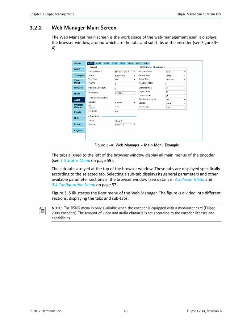
Chapter 3 Ellipse Management Ellipse Management Menu Tree
© 2012 Harmonic Inc. 49 Ellipse r.2.14, Revision A
3.2.2 Web Manager Main Screen
The Web Manager main screen is the work space of the web-management user. It displays the browser window, around which are the tabs and sub-tabs of the encoder (see Figure 3–4).
Figure 3–4: Web Manager – Main Menu Example
The tabs aligned to the left of the browser window display all main menus of the encoder (see 3.5 Status Menu on page 59).
The sub-tabs arrayed at the top of the browser window. These tabs are displayed specifically according to the selected tab. Selecting a sub-tab displays its general parameters and other available parameter sections in the browser window (see details in 3.3 Preset Menu and 3.4 Configuration Menu on page 57).
Figure 3–5 illustrates the Root menu of the Web Manager. The figure is divided into different sections, displaying the tabs and sub-tabs.
NOTE: The DSNG menu is only available when the encoder is equipped with a modulator card (Ellipse 2000 encoders). The amount of video and audio channels is set according to the encoder licenses and capabilities.
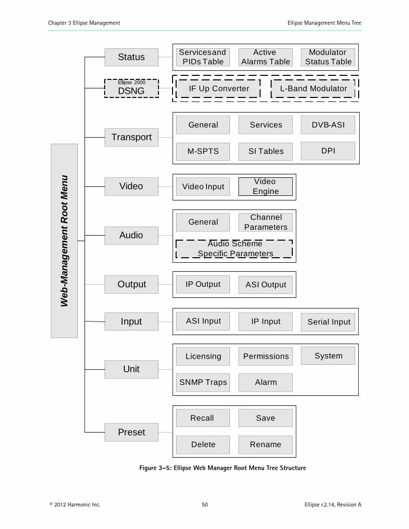
Chapter 3 Ellipse Management Ellipse Management Menu Tree
© 2012 Harmonic Inc. 50 Ellipse r.2.14, Revision A
Figure 3–5: Ellipse Web Manager Root Menu Tree Structure
Web
-Man
agem
ent
Ro
ot
Men
uStatus
Transport
Video
Audio
Ellipse 2000
DSNG
ServicesandPIDs Table
ActiveAlarms Table
ModulatorStatus Table
General Services DVB-ASI
M-SPTS SI Tables
Video InputVideoEngine
General
Audio Scheme Specific Parameters
Output
Unit
Preset
IP Output
Licensing
Recall
Permissions System
SNMP Traps Alarm
Save
Delete Rename
Channel Parameters
L-Band Modulator
ASI Output
Input ASI Input IP Input Serial Input
DPI
IF Up Converter
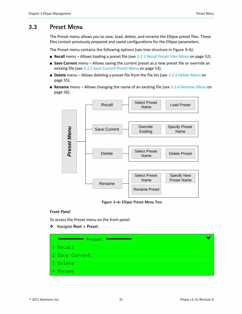
Chapter 3 Ellipse Management Preset Menu
© 2012 Harmonic Inc. 51 Ellipse r.2.14, Revision A
3.3 Preset MenuThe Preset menu allows you to save, load, delete, and rename the Ellipse preset files. These files contain previously prepared and saved configurations for the Ellipse parameters.
The Preset menu contains the following options (see tree structure in Figure 3–6): Recall menu – Allows loading a preset file (see 3.3.1 Recall Preset Files Menu on page 52). Save Current menu – Allows saving the current preset as a new preset file or override an
existing file (see 3.3.2 Save Current Preset Menu on page 53). Delete menu – Allows deleting a preset file from the file list (see 3.3.3 Delete Menu on
page 55). Rename menu – Allows changing the name of an existing file (see 3.3.4 Rename Menu on
page 56).
Figure 3–6: Ellipse Preset Menu Tree
Front Panel
To access the Preset menu on the front panel: Navigate Root > Preset.
Preset
1 Recall
2 Save Current
3 Delete
4 Rename
Delete
Recall
Rename
Select PresetName Load Preset
Select PresetName Delete Preset
Save CurrentOverrideExisting
Specify PresetName
Select PresetName
Specify NewPreset Name
Rename Preset
Pre
set
Men
u
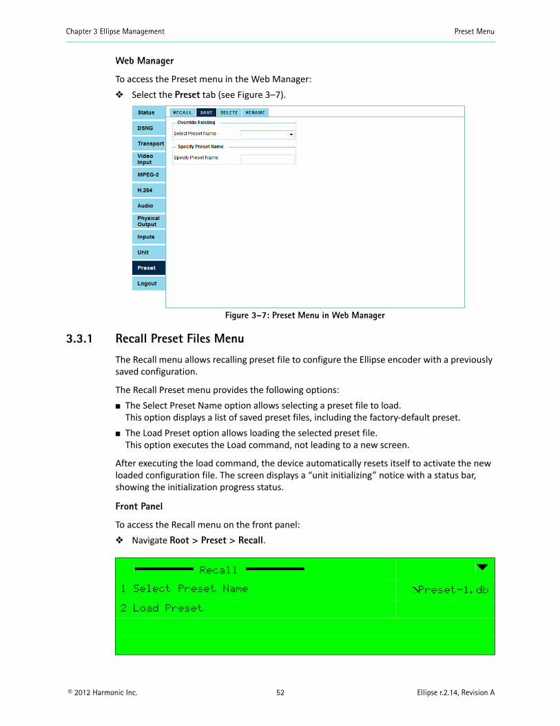
Chapter 3 Ellipse Management Preset Menu
© 2012 Harmonic Inc. 52 Ellipse r.2.14, Revision A
Web Manager
To access the Preset menu in the Web Manager: Select the Preset tab (see Figure 3–7).
Figure 3–7: Preset Menu in Web Manager
3.3.1 Recall Preset Files Menu
The Recall menu allows recalling preset file to configure the Ellipse encoder with a previously saved configuration.
The Recall Preset menu provides the following options: The Select Preset Name option allows selecting a preset file to load.
This option displays a list of saved preset files, including the factory-default preset. The Load Preset option allows loading the selected preset file.
This option executes the Load command, not leading to a new screen.
After executing the load command, the device automatically resets itself to activate the new loaded configuration file. The screen displays a “unit initializing” notice with a status bar, showing the initialization progress status.
Front Panel
To access the Recall menu on the front panel: Navigate Root > Preset > Recall.
Recall
1 Select Preset Name Preset-1.db
2 Load Preset
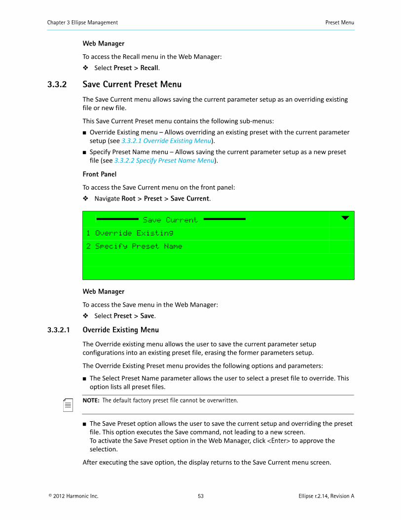
Chapter 3 Ellipse Management Preset Menu
© 2012 Harmonic Inc. 53 Ellipse r.2.14, Revision A
Web Manager
To access the Recall menu in the Web Manager: Select Preset > Recall.
3.3.2 Save Current Preset Menu
The Save Current menu allows saving the current parameter setup as an overriding existing file or new file.
This Save Current Preset menu contains the following sub-menus: Override Existing menu – Allows overriding an existing preset with the current parameter
setup (see 3.3.2.1 Override Existing Menu). Specify Preset Name menu – Allows saving the current parameter setup as a new preset
file (see 3.3.2.2 Specify Preset Name Menu).
Front Panel
To access the Save Current menu on the front panel: Navigate Root > Preset > Save Current.
Web Manager
To access the Save menu in the Web Manager: Select Preset > Save.
3.3.2.1 Override Existing Menu
The Override existing menu allows the user to save the current parameter setup configurations into an existing preset file, erasing the former parameters setup.
The Override Existing Preset menu provides the following options and parameters:
The Select Preset Name parameter allows the user to select a preset file to override. This option lists all preset files.
NOTE: The default factory preset file cannot be overwritten.
The Save Preset option allows the user to save the current setup and overriding the preset file. This option executes the Save command, not leading to a new screen. To activate the Save Preset option in the Web Manager, click <Enter> to approve the selection.
After executing the save option, the display returns to the Save Current menu screen.
Save Current
1 Override Existing
2 Specify Preset Name
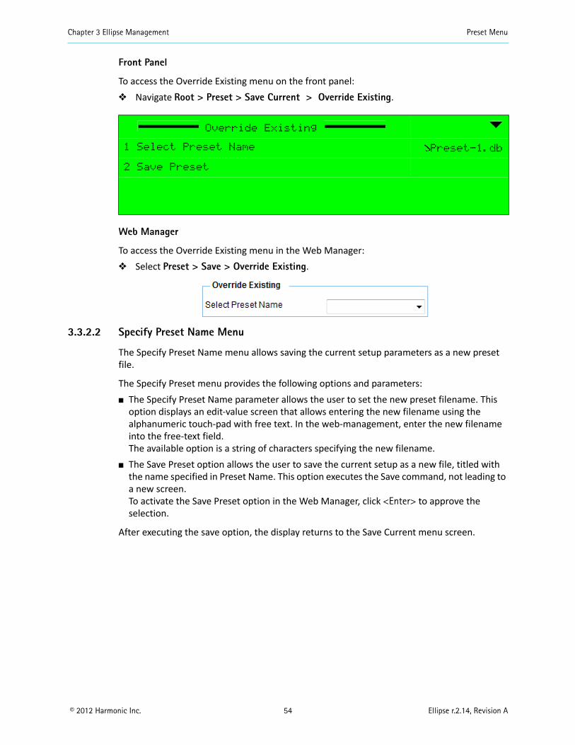
Chapter 3 Ellipse Management Preset Menu
© 2012 Harmonic Inc. 54 Ellipse r.2.14, Revision A
Front Panel
To access the Override Existing menu on the front panel: Navigate Root > Preset > Save Current > Override Existing.
Web Manager
To access the Override Existing menu in the Web Manager: Select Preset > Save > Override Existing.
3.3.2.2 Specify Preset Name Menu
The Specify Preset Name menu allows saving the current setup parameters as a new preset file.
The Specify Preset menu provides the following options and parameters: The Specify Preset Name parameter allows the user to set the new preset filename. This
option displays an edit-value screen that allows entering the new filename using the alphanumeric touch-pad with free text. In the web-management, enter the new filename into the free-text field. The available option is a string of characters specifying the new filename.
The Save Preset option allows the user to save the current setup as a new file, titled with the name specified in Preset Name. This option executes the Save command, not leading to a new screen. To activate the Save Preset option in the Web Manager, click <Enter> to approve the selection.
After executing the save option, the display returns to the Save Current menu screen.
Override Existing
1 Select Preset Name Preset-1.db
2 Save Preset
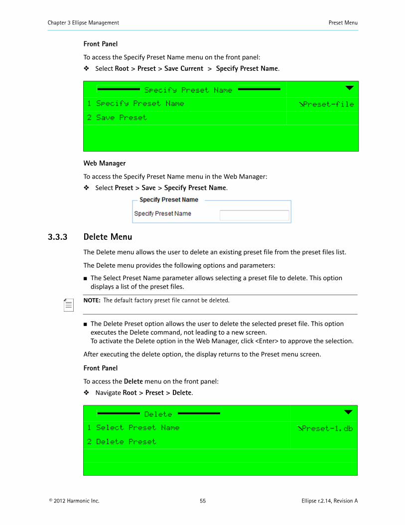
Chapter 3 Ellipse Management Preset Menu
© 2012 Harmonic Inc. 55 Ellipse r.2.14, Revision A
Front Panel
To access the Specify Preset Name menu on the front panel: Select Root > Preset > Save Current > Specify Preset Name.
Web Manager
To access the Specify Preset Name menu in the Web Manager: Select Preset > Save > Specify Preset Name.
3.3.3 Delete Menu
The Delete menu allows the user to delete an existing preset file from the preset files list.
The Delete menu provides the following options and parameters:
The Select Preset Name parameter allows selecting a preset file to delete. This option displays a list of the preset files.
NOTE: The default factory preset file cannot be deleted.
The Delete Preset option allows the user to delete the selected preset file. This option executes the Delete command, not leading to a new screen. To activate the Delete option in the Web Manager, click <Enter> to approve the selection.
After executing the delete option, the display returns to the Preset menu screen.
Front Panel
To access the Delete menu on the front panel: Navigate Root > Preset > Delete.
Specify Preset Name
1 Specify Preset Name Preset-file
2 Save Preset
Delete
1 Select Preset Name Preset-1.db
2 Delete Preset
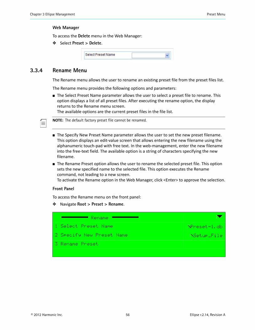
Chapter 3 Ellipse Management Preset Menu
© 2012 Harmonic Inc. 56 Ellipse r.2.14, Revision A
Web Manager
To access the Delete menu in the Web Manager: Select Preset > Delete.
3.3.4 Rename Menu
The Rename menu allows the user to rename an existing preset file from the preset files list.
The Rename menu provides the following options and parameters: The Select Preset Name parameter allows the user to select a preset file to rename. This
option displays a list of all preset files. After executing the rename option, the display returns to the Rename menu screen. The available options are the current preset files in the file list.
NOTE: The default factory preset file cannot be renamed.
The Specify New Preset Name parameter allows the user to set the new preset filename. This option displays an edit-value screen that allows entering the new filename using the alphanumeric touch-pad with free text. In the web-management, enter the new filename into the free-text field. The available option is a string of characters specifying the new filename.
The Rename Preset option allows the user to rename the selected preset file. This option sets the new specified name to the selected file. This option executes the Rename command, not leading to a new screen.To activate the Rename option in the Web Manager, click <Enter> to approve the selection.
Front Panel
To access the Rename menu on the front panel: Navigate Root > Preset > Rename.
Rename
1 Select Preset Name Preset-1.db
2 Specify New Preset Name Setup_File
3 Rename Preset
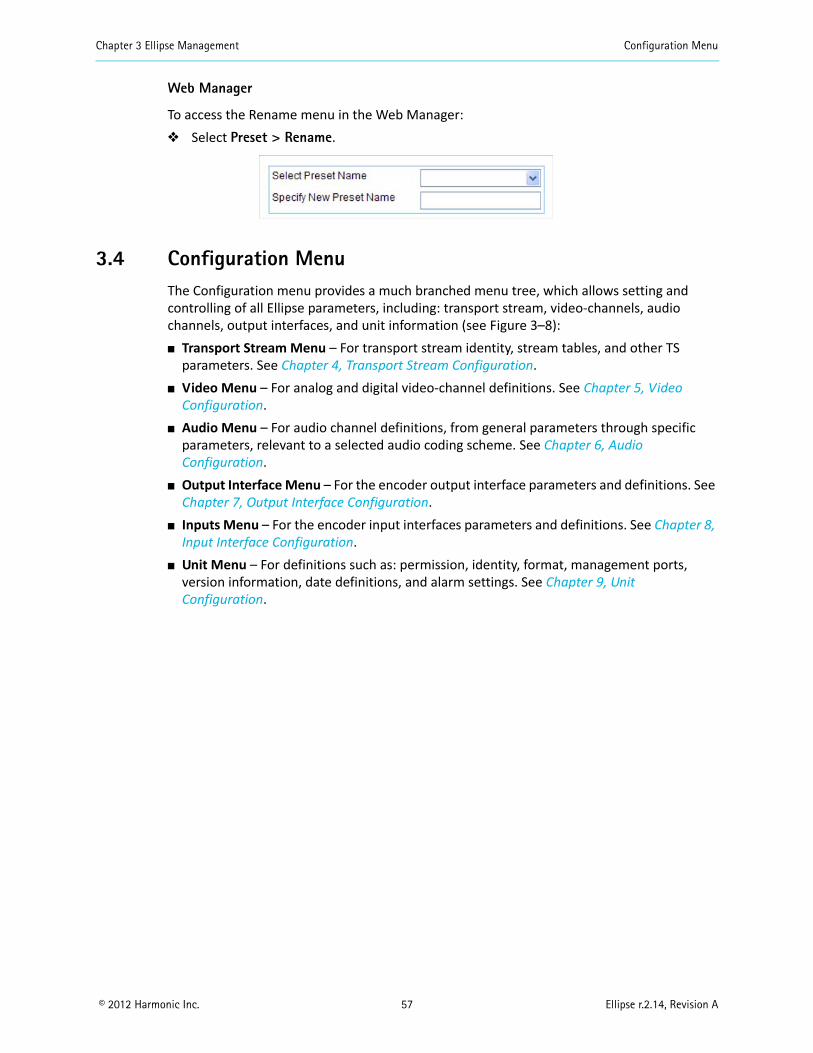
Chapter 3 Ellipse Management Configuration Menu
© 2012 Harmonic Inc. 57 Ellipse r.2.14, Revision A
Web Manager
To access the Rename menu in the Web Manager: Select Preset > Rename.
3.4 Configuration MenuThe Configuration menu provides a much branched menu tree, which allows setting and controlling of all Ellipse parameters, including: transport stream, video-channels, audio channels, output interfaces, and unit information (see Figure 3–8): Transport Stream Menu – For transport stream identity, stream tables, and other TS
parameters. See Chapter 4, Transport Stream Configuration. Video Menu – For analog and digital video-channel definitions. See Chapter 5, Video
Configuration. Audio Menu – For audio channel definitions, from general parameters through specific
parameters, relevant to a selected audio coding scheme. See Chapter 6, Audio Configuration.
Output Interface Menu – For the encoder output interface parameters and definitions. See Chapter 7, Output Interface Configuration.
Inputs Menu – For the encoder input interfaces parameters and definitions. See Chapter 8, Input Interface Configuration.
Unit Menu – For definitions such as: permission, identity, format, management ports, version information, date definitions, and alarm settings. See Chapter 9, Unit Configuration.
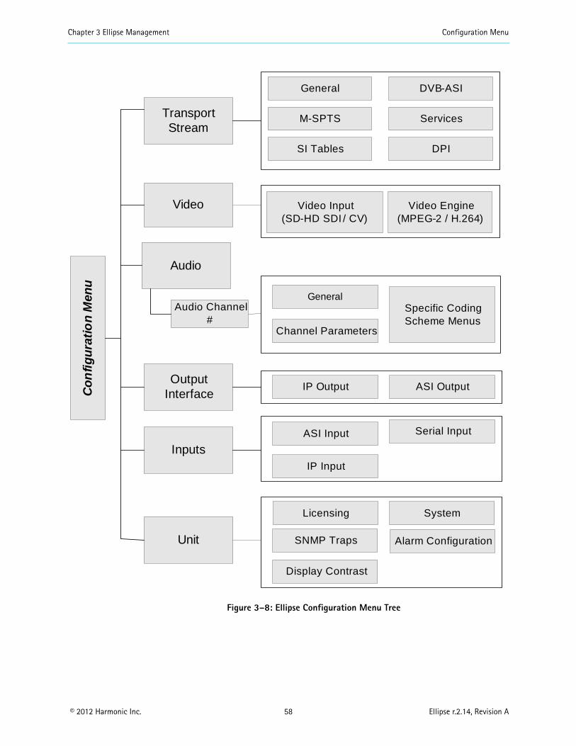
Chapter 3 Ellipse Management Configuration Menu
© 2012 Harmonic Inc. 58 Ellipse r.2.14, Revision A
Figure 3–8: Ellipse Configuration Menu Tree
Co
nfi
gu
rati
on
Men
u
Transport Stream
Output Interface
SI Tables
IP Output
Video Input(SD-HD SDI / CV)
Video Engine (MPEG-2 / H.264)
DPI
Unit
SystemLicensing
M-SPTS Services
General DVB-ASI
Video
Audio Channel #
General
Channel Parameters
Audio
Specific Coding Scheme Menus
SNMP Traps Alarm Configuration
Display Contrast
ASI Output
InputsIP Input
ASI Input Serial Input
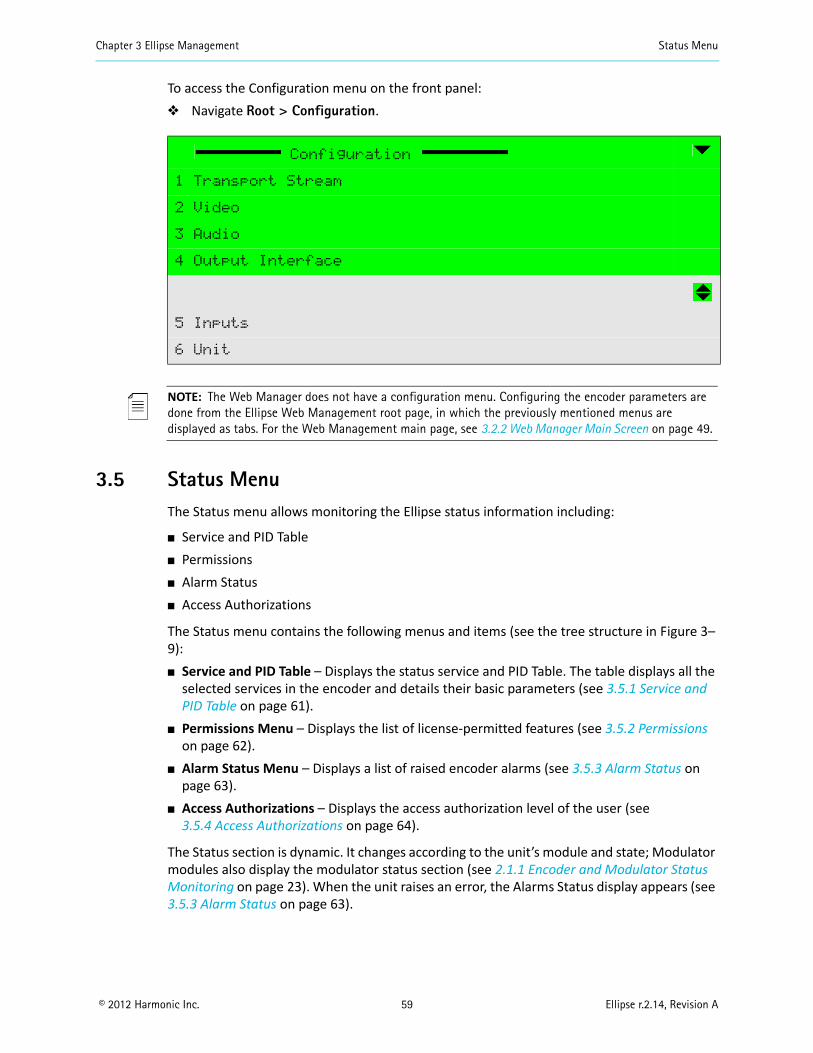
Chapter 3 Ellipse Management Status Menu
© 2012 Harmonic Inc. 59 Ellipse r.2.14, Revision A
To access the Configuration menu on the front panel: Navigate Root > Configuration.
NOTE: The Web Manager does not have a configuration menu. Configuring the encoder parameters are done from the Ellipse Web Management root page, in which the previously mentioned menus are displayed as tabs. For the Web Management main page, see 3.2.2 Web Manager Main Screen on page 49.
3.5 Status MenuThe Status menu allows monitoring the Ellipse status information including:
Service and PID Table Permissions Alarm Status Access Authorizations
The Status menu contains the following menus and items (see the tree structure in Figure 3–9): Service and PID Table – Displays the status service and PID Table. The table displays all the
selected services in the encoder and details their basic parameters (see 3.5.1 Service and PID Table on page 61).
Permissions Menu – Displays the list of license-permitted features (see 3.5.2 Permissions on page 62).
Alarm Status Menu – Displays a list of raised encoder alarms (see 3.5.3 Alarm Status on page 63).
Access Authorizations – Displays the access authorization level of the user (see 3.5.4 Access Authorizations on page 64).
The Status section is dynamic. It changes according to the unit’s module and state; Modulator modules also display the modulator status section (see 2.1.1 Encoder and Modulator Status Monitoring on page 23). When the unit raises an error, the Alarms Status display appears (see 3.5.3 Alarm Status on page 63).
Configuration
1 Transport Stream
2 Video
3 Audio
4 Output Interface
5 Inputs
6 Unit
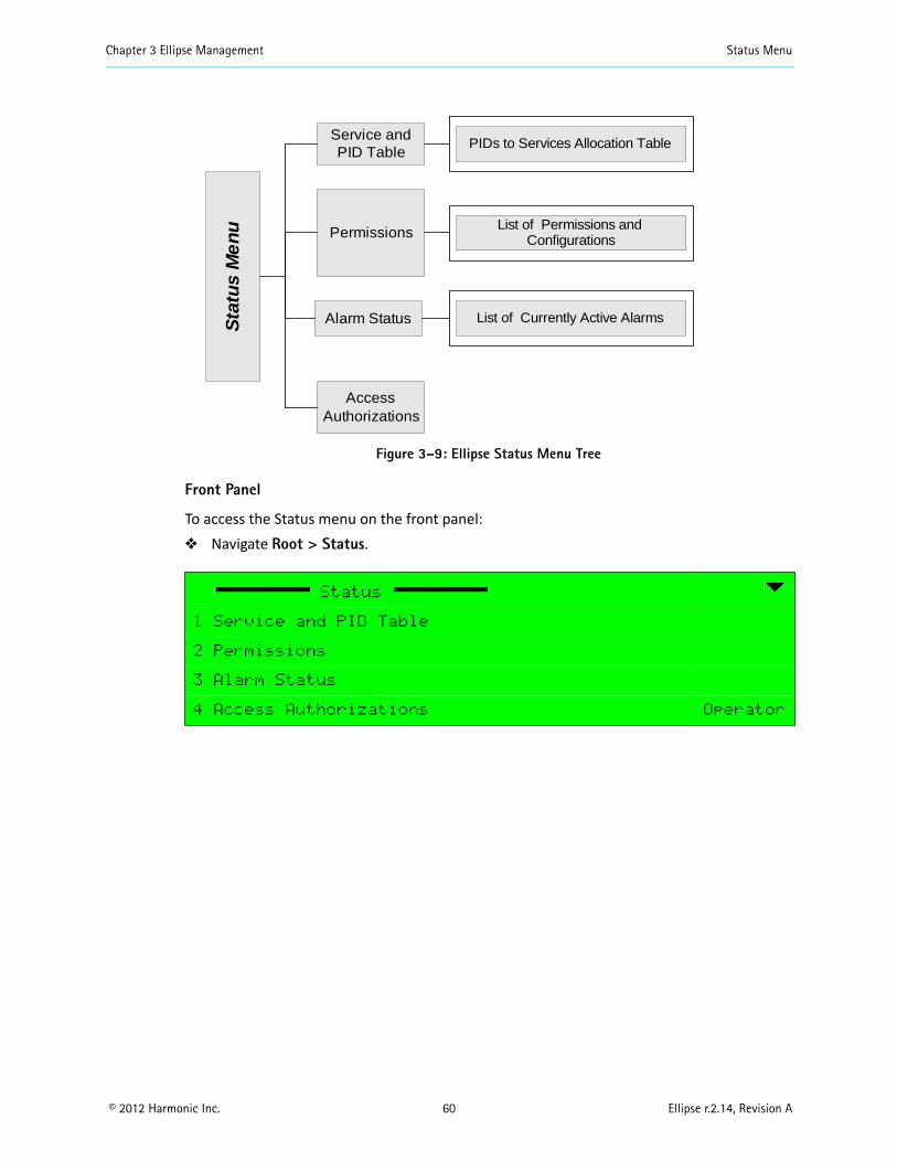
Chapter 3 Ellipse Management Status Menu
© 2012 Harmonic Inc. 60 Ellipse r.2.14, Revision A
Figure 3–9: Ellipse Status Menu Tree
Front Panel
To access the Status menu on the front panel: Navigate Root > Status.
Status
1 Service and PID Table
2 Permissions
3 Alarm Status
4 Access Authorizations Operator
Service and PID Table
Access Authorizations
PIDs to Services Allocation Table
PermissionsList of Permissions and
Configurations S
tatu
s M
en
u
Alarm Status List of Currently Active Alarms
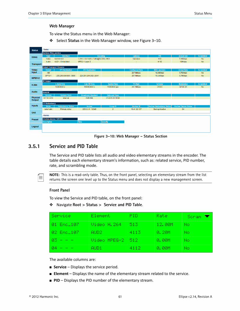
Chapter 3 Ellipse Management Status Menu
© 2012 Harmonic Inc. 61 Ellipse r.2.14, Revision A
Web Manager
To view the Status menu in the Web Manager: Select Status in the Web Manager window, see Figure 3–10.
Figure 3–10: Web Manager – Status Section
3.5.1 Service and PID Table
The Service and PID table lists all audio and video elementary streams in the encoder. The table details each elementary stream's information, such as: related service, PID number, rate, and scrambling mode.
NOTE: This is a read-only table. Thus, on the front panel, selecting an elementary stream from the list returns the screen one level up to the Status menu and does not display a new management screen.
Front Panel
To view the Service and PID table, on the front panel: Navigate Root > Status > Service and PID Table.
The available columns are:
Service – Displays the service period. Element – Displays the name of the elementary stream related to the service. PID – Displays the PID number of the elementary stream.
Service Element PID Rate Scram
01 Enc_107 Video H.264 513 12.00M No
02 Enc_107 AUD2 4113 0.20M No
03 - - - Video MPEG-2 512 0.00M No
04 - - - AUD1 4112 0.00M No
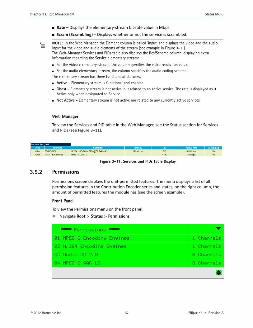
Chapter 3 Ellipse Management Status Menu
© 2012 Harmonic Inc. 62 Ellipse r.2.14, Revision A
Rate – Displays the elementary-stream bit-rate value in Mbps. Scram (Scrambling) – Displays whether or not the service is scrambled.
NOTE: In the Web Manager, the Element column is called 'Input' and displays the video and the audio input for the video and audio elements of the stream (see example in Figure 3–11). The Web-Manager Services and PIDs table also displays the Res/Scheme column, displaying extra information regarding the Service elementary stream:
For the video elementary-stream, the column specifies the video resolution value.
For the audio elementary-stream, the column specifies the audio coding scheme.The elementary stream has three functions at statuses:
Active – Elementary stream is functional and enabled.
Ghost – Elementary stream is not active, but related to an active service. The rate is displayed as 0. Active only when designated to Service.
Not Active – Elementary stream is not active nor related to any currently active services.
Web Manager
To view the Services and PID table in the Web Manager, see the Status section for Services and PIDs (see Figure 3–11).
Figure 3–11: Services and PIDs Table Display
3.5.2 Permissions
Permissions screen displays the unit-permitted features. The menu displays a list of all permission features in the Contribution Encoder series and states, on the right column, the amount of permitted features the module has (see the screen example).
Front Panel
To view the Permissions menu on the front panel: Navigate Root > Status > Permissions.
Permissions
01 MPEG-2 Encoding Engines 1 Channels
02 H.264 Encoding Engines 1 Channels
03 Audio DD 2.0 8 Channels
04 MPEG-2 AAC LC 8 Channels
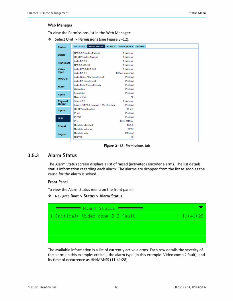
Chapter 3 Ellipse Management Status Menu
© 2012 Harmonic Inc. 63 Ellipse r.2.14, Revision A
Web Manager
To view the Permissions list in the Web Manager: Select Unit > Permissions (see Figure 3–12).
Figure 3–12: Permissions tab
3.5.3 Alarm Status
The Alarm Status screen displays a list of raised (activated) encoder alarms. The list details status information regarding each alarm. The alarms are dropped from the list as soon as the cause for the alarm is solved.
Front Panel
To view the Alarm Status menu on the front panel: Navigate Root > Status > Alarm Status.
The available information is a list of currently active alarms. Each row details the severity of the alarm (in this example: critical), the alarm type (in this example: Video comp 2 fault), and its time of occurrence as HH:MM:SS (11:41:28).
Alarm Status
1 Critical: Video comp 2 2 fault 11:41:28
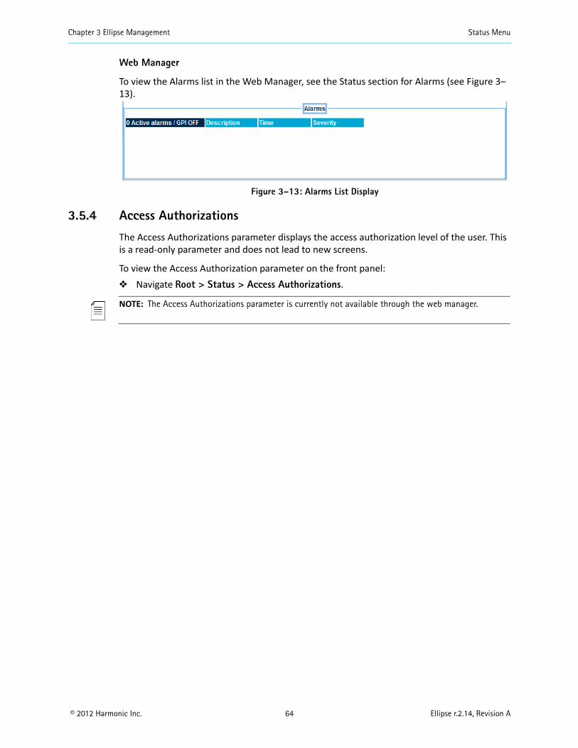
Chapter 3 Ellipse Management Status Menu
© 2012 Harmonic Inc. 64 Ellipse r.2.14, Revision A
Web Manager
To view the Alarms list in the Web Manager, see the Status section for Alarms (see Figure 3–13).
Figure 3–13: Alarms List Display
3.5.4 Access Authorizations
The Access Authorizations parameter displays the access authorization level of the user. This is a read-only parameter and does not lead to new screens.
To view the Access Authorization parameter on the front panel: Navigate Root > Status > Access Authorizations.
NOTE: The Access Authorizations parameter is currently not available through the web manager.
© 2012 Harmonic Inc. 65 Ellipse r.2.14, Revision A
Chapter 4Transport Stream Configuration
The Transport Stream menu controls the setting of the transport stream for the Ellipse encoder. This menu sets the transport stream: identity, format, parameters, services, and stream-information tables.
Topics: TS General Menu/Tab – Sets the general parameters of the transport stream. DVB-ASI Interface Menu – Sets the DVB-ASI interface parameters for the transport streams. M-SPTS Menu/Tab – Manages the IP interface for multiple program transport streams. Services Menu – Manages the services configuration on the transport streams. SI Tables Menu/Tab – Sets the mode of inclusion of SI tables and the parameters of the
various SI tables in the stream. DPI Menu – Sets the insertion of the Cue Tone trigger for commercial needs.
See Figure 4–1 for a diagram of the menus.
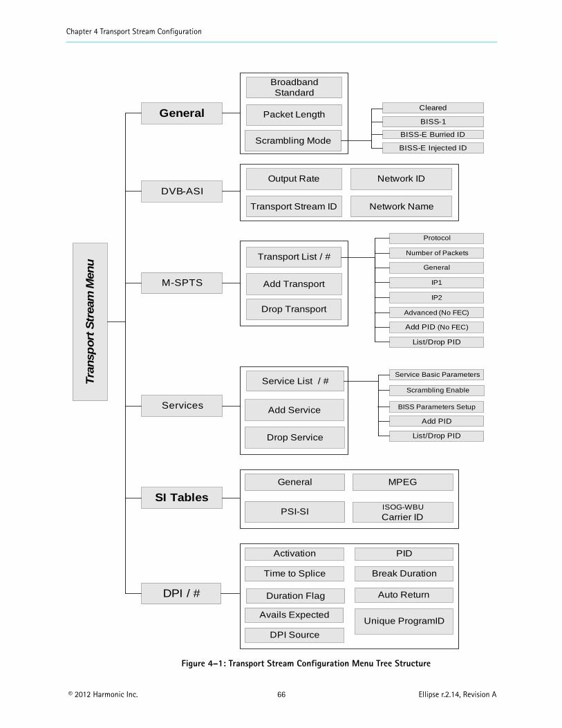
Chapter 4 Transport Stream Configuration
© 2012 Harmonic Inc. 66 Ellipse r.2.14, Revision A
Figure 4–1: Transport Stream Configuration Menu Tree Structure
Tra
nsp
ort
Str
eam
Men
u
General
DVB-ASIOutput Rate Network ID
Transport Stream ID
DPI / #
General MPEG
Packet Length
Broadband Standard
M-SPTS Add Transport
Drop Transport
Avails ExpectedUnique ProgramID
Duration Flag Auto Return
Network Name
Scrambling Mode
Transport List / #
Services Add Service
Drop Service
Service List / #Service Basic Parameters
Add PID
List/Drop PID
PSI-SIISOG-WBU
Carrier ID
SI Tables
Time to Splice Break Duration
Activation PID
DPI Source
BISS-E Burried ID
BISS-1
BISS-E Injected ID
Cleared
Protocol
List/Drop PID
General
Number of Packets
Add PID (No FEC)
Scrambling Enable
BISS Parameters Setup
IP1
IP2
Advanced (No FEC)
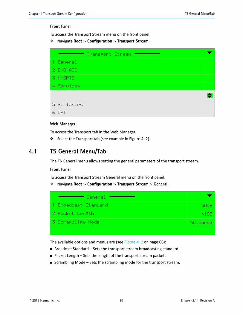
Chapter 4 Transport Stream Configuration TS General Menu/Tab
© 2012 Harmonic Inc. 67 Ellipse r.2.14, Revision A
Front Panel
To access the Transport Stream menu on the front panel: Navigate Root > Configuration > Transport Stream.
Web Manager
To access the Transport tab in the Web Manager: Select the Transport tab (see example in Figure 4–2).
4.1 TS General Menu/TabThe TS General menu allows setting the general parameters of the transport stream.
Front Panel
To access the Transport Stream General menu on the front panel: Navigate Root > Configuration > Transport Stream > General.
The available options and menus are (see Figure 4–1 on page 66): Broadcast Standard – Sets the transport stream broadcasting standard. Packet Length – Sets the length of the transport stream packet. Scrambling Mode – Sets the scrambling mode for the transport stream.
Transport Stream
1 General
2 DVB-ASI
3 M-SPTS
4 Services
5 SI Tables
6 DPI
General
1 Broadcast Standard DVB
2 Packet Length 188
3 Scrambling Mode Cleared
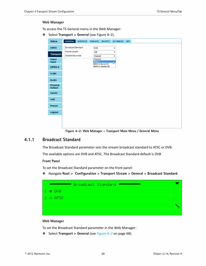
Chapter 4 Transport Stream Configuration TS General Menu/Tab
© 2012 Harmonic Inc. 68 Ellipse r.2.14, Revision A
Web Manager
To access the TS General menu in the Web Manager: Select Transport > General (see Figure 4–2).
Figure 4–2: Web Manager – Transport Main Menu / General Menu
4.1.1 Broadcast Standard
The Broadcast Standard parameter sets the stream broadcast standard to ATSC or DVB.
The available options are DVB and ATSC. The Broadcast Standard default is DVB.
Front Panel
To set the Broadcast Standard parameter on the front panel: Navigate Root > Configuration > Transport Stream > General > Broadcast Standard.
Web Manager
To set the Broadcast Standard parameter in the Web Manager: Select Transport > General (see Figure 4–2 on page 68).
Broadcast Standard
1 ƒ DVB
2 ‚ ATSC
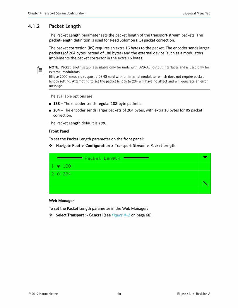
Chapter 4 Transport Stream Configuration TS General Menu/Tab
© 2012 Harmonic Inc. 69 Ellipse r.2.14, Revision A
4.1.2 Packet Length
The Packet Length parameter sets the packet length of the transport-stream packets. The packet-length definition is used for Reed Solomon (RS) packet correction.
The packet correction (RS) requires an extra 16 bytes to the packet. The encoder sends larger packets (of 204 bytes instead of 188 bytes) and the external device (such as a modulator) implements the packet corrector in the extra 16 bytes.
NOTE: Packet length setup is available only for units with DVB-ASI output interfaces and is used only for external modulators.Ellipse 2000 encoders support a DSNG card with an internal modulator which does not require packet-length setting. Attempting to set the packet length to 204 will have no affect and will generate an error message.
The available options are:
188 – The encoder sends regular 188-byte packets. 204 – The encoder sends larger packets of 204 bytes, with extra 16 bytes for RS packet
correction.
The Packet Length default is 188.
Front Panel
To set the Packet Length parameter on the front panel: Navigate Root > Configuration > Transport Stream > Packet Length.
Web Manager
To set the Packet Length parameter in the Web Manager: Select Transport > General (see Figure 4–2 on page 68).
Packet Length
1 ƒ 188
2 ‚ 204
Chapter 4 Transport Stream Configuration TS General Menu/Tab
© 2012 Harmonic Inc. 70 Ellipse r.2.14, Revision A
4.1.3 Scrambling Mode
The Basic Interoperable Scrambling System (BISS) is based on the DVB common scrambling algorithm. It provides secured (scrambled) transmissions between DSNG equipment from any supplier using a scrambling key known to the encoding and to the decoding equipment.
The advanced BISS-E Specification enables the use of scrambling keys which are encrypted, or session words. This adds another layer of security to the transmissions while fully retaining the benefits of inter-operability. The keys for unscrambling the transmission require the corresponding DES process and a secret identifier buried in the equipment.
There are four scrambling level, defined by the BISS and supported by the Ellipse: Clear, where no scrambling is applied on the stream. BISS-1, using a scrambling key which is clear, i.e., not encrypted. BISS-E Buried ID, where the scrambling key is encrypted and buried in the equipment
hardware. BISS-E Injected ID, where the scrambling key is encrypted and requires an injected
identification code.
The Scrambling Mode menu/box sets the Ellipse encoder scrambling mode and method.
NOTE: Defining a scrambling method for the encoder determines the scrambling level for all relevant features of the encoder:
The Encoder Cascading feature (for details see 7.3 ASI Output Menu for DVB-ASI Output scrambling and 8.2 DVB-ASI Input for DVB-ASI Input scrambling).
The Transport Stream Service scrambling feature (for details, see 4.4.3).
The available options are: Clear – Transport stream is clear of scrambling. BISS-1 – Transport stream is scrambled using BISS-1 mode. BISS-E Buried ID – Transport stream is scrambled using BISS-E buried ID mode. BISS-E Injected ID – Transport stream is scrambled using BISS-E injected ID mode.
NOTE: Setting the Encoder Scrambling Mode parameter to other modes than Clear is performed upon permission only, with a correct license key. When trying to change the Clear scrambling mode without permission, a no permission message displays.
The default mode is Clear.
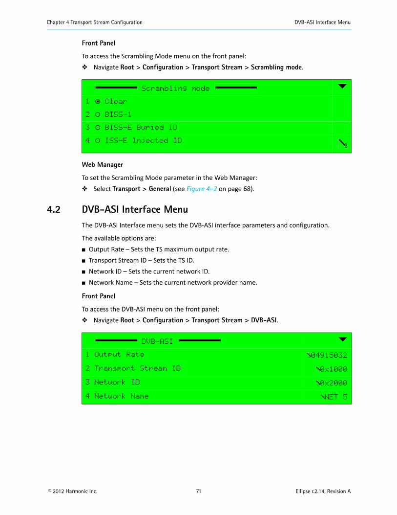
Chapter 4 Transport Stream Configuration DVB-ASI Interface Menu
© 2012 Harmonic Inc. 71 Ellipse r.2.14, Revision A
Front Panel
To access the Scrambling Mode menu on the front panel: Navigate Root > Configuration > Transport Stream > Scrambling mode.
Web Manager
To set the Scrambling Mode parameter in the Web Manager: Select Transport > General (see Figure 4–2 on page 68).
4.2 DVB-ASI Interface MenuThe DVB-ASI Interface menu sets the DVB-ASI interface parameters and configuration.
The available options are: Output Rate – Sets the TS maximum output rate. Transport Stream ID – Sets the TS ID. Network ID – Sets the current network ID. Network Name – Sets the current network provider name.
Front Panel
To access the DVB-ASI menu on the front panel: Navigate Root > Configuration > Transport Stream > DVB-ASI.
Scrambling mode
1 ƒ Clear
2 ‚ BISS-1
3 ‚ BISS-E Buried ID
4 ‚ ISS-E Injected ID
DVB-ASI
1 Output Rate 04915032
2 Transport Stream ID 0x1000
3 Network ID 0x2000
4 Network Name NET 5
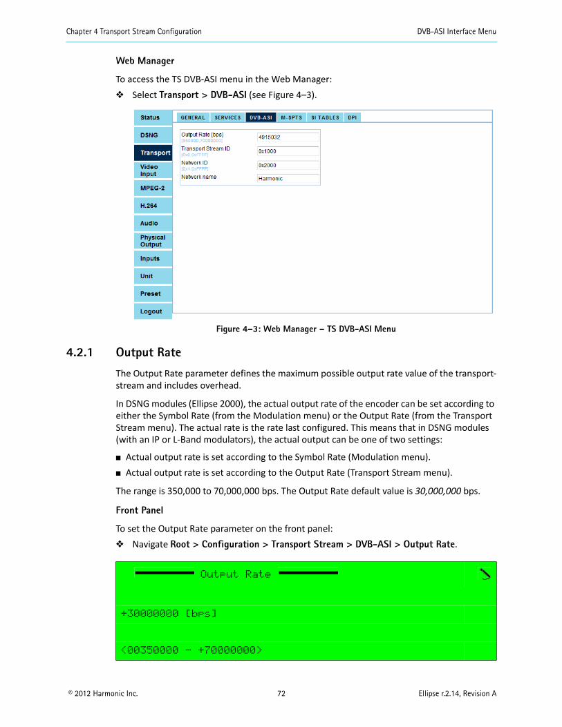
Chapter 4 Transport Stream Configuration DVB-ASI Interface Menu
© 2012 Harmonic Inc. 72 Ellipse r.2.14, Revision A
Web Manager
To access the TS DVB-ASI menu in the Web Manager: Select Transport > DVB-ASI (see Figure 4–3).
Figure 4–3: Web Manager – TS DVB-ASI Menu
4.2.1 Output Rate
The Output Rate parameter defines the maximum possible output rate value of the transport-stream and includes overhead.
In DSNG modules (Ellipse 2000), the actual output rate of the encoder can be set according to either the Symbol Rate (from the Modulation menu) or the Output Rate (from the Transport Stream menu). The actual rate is the rate last configured. This means that in DSNG modules (with an IP or L-Band modulators), the actual output can be one of two settings:
Actual output rate is set according to the Symbol Rate (Modulation menu). Actual output rate is set according to the Output Rate (Transport Stream menu).
The range is 350,000 to 70,000,000 bps. The Output Rate default value is 30,000,000 bps.
Front Panel
To set the Output Rate parameter on the front panel: Navigate Root > Configuration > Transport Stream > DVB-ASI > Output Rate.
Output Rate
+30000000 [bps]
<00350000 - +70000000>

Chapter 4 Transport Stream Configuration DVB-ASI Interface Menu
© 2012 Harmonic Inc. 73 Ellipse r.2.14, Revision A
Web Manager
To set the Output Rate parameter in the Web Manager: Select Transport > DVB-ASI (see Figure 4–3 on page 72).
4.2.2 Transport Stream ID
The Transport Stream ID parameter sets the transport stream ID number using hexadecimal numbers.
The range is 0x0 to 0xFFFF (Hexadecimal). The Transport Stream ID default value is 0x1000.
Front Panel
To set the Transport Stream ID parameter on the front panel: Navigate Root > Configuration > Transport Stream > DVB-ASI > Transport Stream ID.
Web Manager
To set the Transport Stream ID parameter in the Web Manager: Select Transport > DVB-ASI (see Figure 4–3 on page 72).
4.2.3 Network ID
The Network ID parameter sets the Network ID number using hexadecimal numbers.
The range is 0x1 to 0xFFFF (Hexadecimal). The Network ID default value is 0x2000.
Front Panel
To set the Network ID parameter on the front panel: Navigate Root > Configuration > Transport Stream > DVB-ASI > Network ID.
Transport Stream ID
0x1000 [Hex]
<0x0 - 0xffff>
Network ID
0x2000 [Hex]
<0x1 - 0xffff>
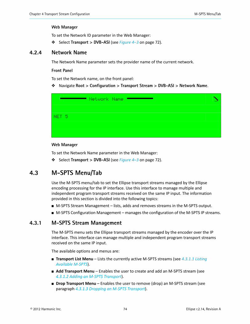
Chapter 4 Transport Stream Configuration M-SPTS Menu/Tab
© 2012 Harmonic Inc. 74 Ellipse r.2.14, Revision A
Web Manager
To set the Network ID parameter in the Web Manager: Select Transport > DVB-ASI (see Figure 4–3 on page 72).
4.2.4 Network Name
The Network Name parameter sets the provider name of the current network.
Front Panel
To set the Network name, on the front panel: Navigate Root > Configuration > Transport Stream > DVB-ASI > Network Name.
Web Manager
To set the Network Name parameter in the Web Manager: Select Transport > DVB-ASI (see Figure 4–3 on page 72).
4.3 M-SPTS Menu/TabUse the M-SPTS menu/tab to set the Ellipse transport streams managed by the Ellipse encoding processing for the IP interface. Use this interface to manage multiple and independent program transport streams received on the same IP input. The information provided in this section is divided into the following topics: M-SPTS Stream Management – lists, adds and removes streams in the M-SPTS output. M-SPTS Configuration Management – manages the configuration of the M-SPTS IP streams.
4.3.1 M-SPTS Stream Management
The M-SPTS menu sets the Ellipse transport streams managed by the encoder over the IP interface. This interface can manage multiple and independent program transport streams received on the same IP input.
The available options and menus are:
Transport List Menu – Lists the currently active M-SPTS streams (see 4.3.1.1 Listing Available M-SPTS).
Add Transport Menu – Enables the user to create and add an M-SPTS stream (see 4.3.1.2 Adding an M-SPTS Transport).
Drop Transport Menu – Enables the user to remove (drop) an M-SPTS stream (see paragraph 4.3.1.3 Dropping an M-SPTS Transport).
Network Name
NET 5
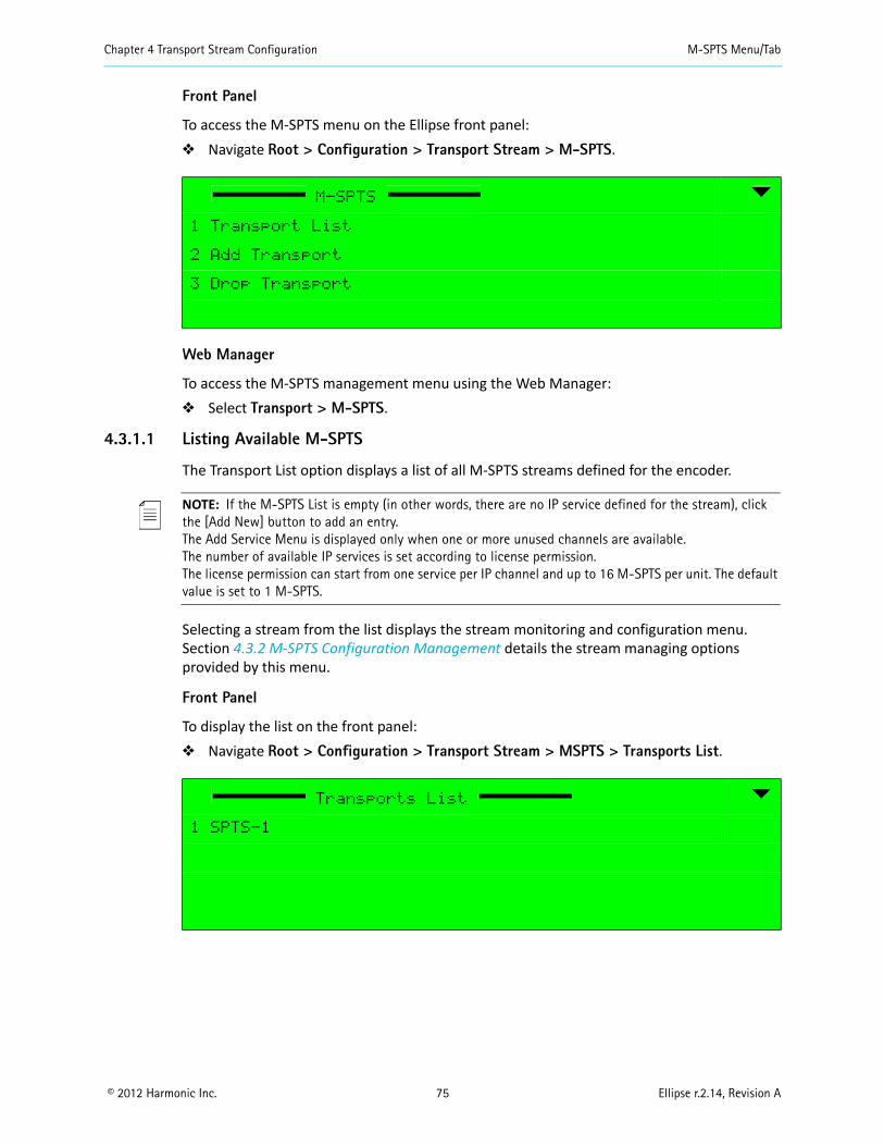
Chapter 4 Transport Stream Configuration M-SPTS Menu/Tab
© 2012 Harmonic Inc. 75 Ellipse r.2.14, Revision A
Front Panel
To access the M-SPTS menu on the Ellipse front panel: Navigate Root > Configuration > Transport Stream > M-SPTS.
Web Manager
To access the M-SPTS management menu using the Web Manager: Select Transport > M-SPTS.
4.3.1.1 Listing Available M-SPTS
The Transport List option displays a list of all M-SPTS streams defined for the encoder.
NOTE: If the M-SPTS List is empty (in other words, there are no IP service defined for the stream), click the [Add New] button to add an entry.The Add Service Menu is displayed only when one or more unused channels are available.The number of available IP services is set according to license permission. The license permission can start from one service per IP channel and up to 16 M-SPTS per unit. The default value is set to 1 M-SPTS.
Selecting a stream from the list displays the stream monitoring and configuration menu. Section 4.3.2 M-SPTS Configuration Management details the stream managing options provided by this menu.
Front Panel
To display the list on the front panel: Navigate Root > Configuration > Transport Stream > MSPTS > Transports List.
M-SPTS
1 Transport List
2 Add Transport
3 Drop Transport
Transports List
1 SPTS-1
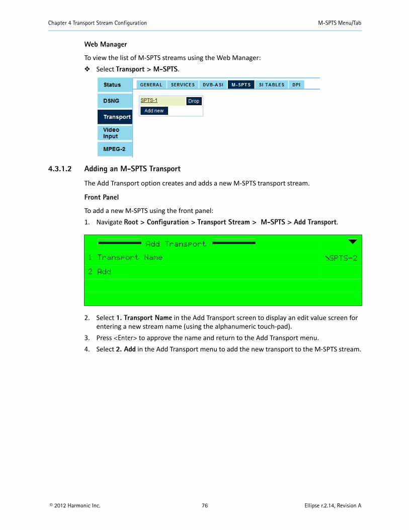
Chapter 4 Transport Stream Configuration M-SPTS Menu/Tab
© 2012 Harmonic Inc. 76 Ellipse r.2.14, Revision A
Web Manager
To view the list of M-SPTS streams using the Web Manager: Select Transport > M-SPTS.
4.3.1.2 Adding an M-SPTS Transport
The Add Transport option creates and adds a new M-SPTS transport stream.
Front Panel
To add a new M-SPTS using the front panel:1. Navigate Root > Configuration > Transport Stream > M-SPTS > Add Transport.
2. Select 1. Transport Name in the Add Transport screen to display an edit value screen for entering a new stream name (using the alphanumeric touch-pad).
3. Press <Enter> to approve the name and return to the Add Transport menu.4. Select 2. Add in the Add Transport menu to add the new transport to the M-SPTS stream.
Add Transport
1 Transport Name SPTS-2
2 Add
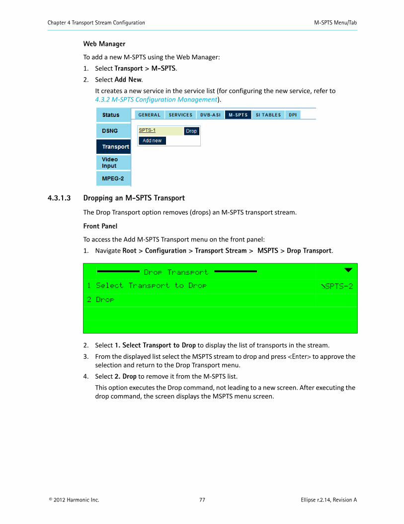
Chapter 4 Transport Stream Configuration M-SPTS Menu/Tab
© 2012 Harmonic Inc. 77 Ellipse r.2.14, Revision A
Web Manager
To add a new M-SPTS using the Web Manager:1. Select Transport > M-SPTS.2. Select Add New.
It creates a new service in the service list (for configuring the new service, refer to 4.3.2 M-SPTS Configuration Management).
4.3.1.3 Dropping an M-SPTS Transport
The Drop Transport option removes (drops) an M-SPTS transport stream.
Front Panel
To access the Add M-SPTS Transport menu on the front panel:1. Navigate Root > Configuration > Transport Stream > MSPTS > Drop Transport.
2. Select 1. Select Transport to Drop to display the list of transports in the stream.3. From the displayed list select the MSPTS stream to drop and press <Enter> to approve the
selection and return to the Drop Transport menu.4. Select 2. Drop to remove it from the M-SPTS list.
This option executes the Drop command, not leading to a new screen. After executing the drop command, the screen displays the MSPTS menu screen.
Drop Transport
1 Select Transport to Drop SPTS-2
2 Drop
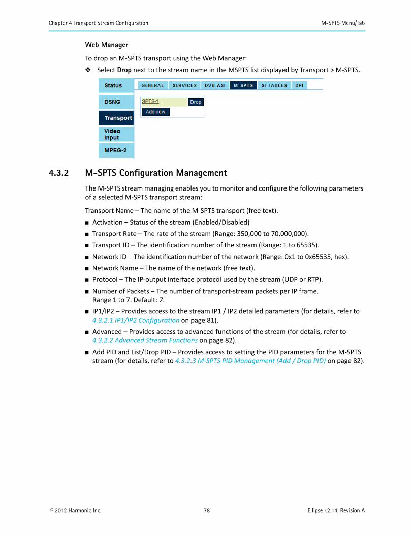
Chapter 4 Transport Stream Configuration M-SPTS Menu/Tab
© 2012 Harmonic Inc. 78 Ellipse r.2.14, Revision A
Web Manager
To drop an M-SPTS transport using the Web Manager: Select Drop next to the stream name in the MSPTS list displayed by Transport > M-SPTS.
4.3.2 M-SPTS Configuration Management
The M-SPTS stream managing enables you to monitor and configure the following parameters of a selected M-SPTS transport stream:
Transport Name – The name of the M-SPTS transport (free text). Activation – Status of the stream (Enabled/Disabled) Transport Rate – The rate of the stream (Range: 350,000 to 70,000,000). Transport ID – The identification number of the stream (Range: 1 to 65535). Network ID – The identification number of the network (Range: 0x1 to 0x65535, hex). Network Name – The name of the network (free text). Protocol – The IP-output interface protocol used by the stream (UDP or RTP). Number of Packets – The number of transport-stream packets per IP frame.
Range 1 to 7. Default: 7. IP1/IP2 – Provides access to the stream IP1 / IP2 detailed parameters (for details, refer to
4.3.2.1 IP1/IP2 Configuration on page 81). Advanced – Provides access to advanced functions of the stream (for details, refer to
4.3.2.2 Advanced Stream Functions on page 82). Add PID and List/Drop PID – Provides access to setting the PID parameters for the M-SPTS
stream (for details, refer to 4.3.2.3 M-SPTS PID Management (Add / Drop PID) on page 82).
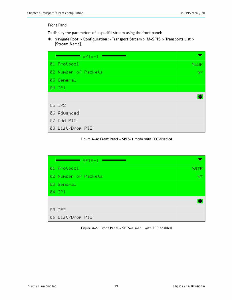
Chapter 4 Transport Stream Configuration M-SPTS Menu/Tab
© 2012 Harmonic Inc. 79 Ellipse r.2.14, Revision A
Front Panel
To display the parameters of a specific stream using the front panel: Navigate Root > Configuration > Transport Stream > M-SPTS > Transports List >
[Stream Name].
Figure 4–4: Front Panel - SPTS-1 menu with FEC disabled
Figure 4–5: Front Panel - SPTS-1 menu with FEC enabled
SPTS-1
01 Protocol UDP
02 Number of Packets 7
03 General
04 IP1
05 IP2
06 Advanced
07 Add PID
08 List/Drop PID
SPTS-1
01 Protocol RTP
02 Number of Packets 7
03 General
04 IP1
05 IP2
06 List/Drop PID
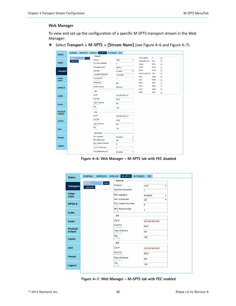
Chapter 4 Transport Stream Configuration M-SPTS Menu/Tab
© 2012 Harmonic Inc. 80 Ellipse r.2.14, Revision A
Web Manager
To view and set-up the configuration of a specific M-SPTS transport stream in the Web Manager: Select Transport > M-SPTS > [Stream Name] (see Figure 4–6 and Figure 4–7).
Figure 4–6: Web Manager – M-SPTS tab with FEC disabled
Figure 4–7: Web Manager - M-SPTS tab with FEC enabled

Chapter 4 Transport Stream Configuration M-SPTS Menu/Tab
© 2012 Harmonic Inc. 81 Ellipse r.2.14, Revision A
4.3.2.1 IP1/IP2 Configuration
The IP1/IP2 Configuration Menu provides access to the IP parameters.
The IP1/IP2 features enabled for managing are: Dst IP – sets the IP destination address. Dst Port – sets the IP destination port number. The range is 01 to 65535. Type of Service – sets the type of service selected for the stream.
The range is 0 to 0x7f [hexadecimal]. TTL – sets the TTL for the stream. The range is 0 to 256.
Front Panel
To set the Ellipse encoder IP parameters on the front panel: Navigate
Root > Configuration > Transport Stream > M-SPTS > Transports List > [MPTS Name]> IP1/IP2.
Web Manager
To access the IP1/IP2 setup menu in the Web Manager: Select Transport > M-SPTS > [Stream Name] and go to the IP1/IP2 area.
IP1
1 Dst IP 224.251.251.001
2 Dst Port 2000
3 Type of Service 0x0
4 TTL 128
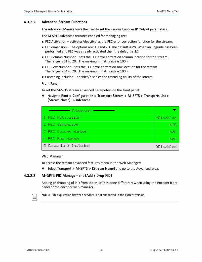
Chapter 4 Transport Stream Configuration M-SPTS Menu/Tab
© 2012 Harmonic Inc. 82 Ellipse r.2.14, Revision A
4.3.2.2 Advanced Stream Functions
The Advanced Menu allows the user to set the various Encoder IP Output parameters.
The M-SPTS Advanced features enabled for managing are: FEC Activation – activates/deactivates the FEC error correction function for the stream. FEC dimension – The options are: 1D and 2D. The default is 2D. When an upgrade has been
performed and FEC was already activated then the default is 1D. FEC Column Number – sets the FEC error correction column location for the stream.
The range is 01 to 20. (The maximum matrix size is 100.) FEC Row Number – sets the FEC error correction row location for the stream.
The range is 04 to 20. (The maximum matrix size is 100.) Cascading Included – enables/disables the cascading ability of the stream.
Front Panel
To set the M-SPTS stream advanced parameters on the front panel: Navigate Root > Configuration > Transport Stream > M-SPTS > Transports List >
[Stream Name] > Advanced.
Web Manager
To access the stream advanced features menu in the Web Manager: Select Transport > M-SPTS > [Stream Name] and go to the Advanced area.
4.3.2.3 M-SPTS PID Management (Add / Drop PID)
Adding or dropping of PID from the M-SPTS is done differently when using the encoder front panel or the encoder web manager.
NOTE: PID duplication between services is not supported in the current version.
Advanced
1 FEC Activation Disabled
2 FEC dimension 2D
3 FEC Column Number 06
4 FEC Row Number 06
5 Cascading Included Disabled
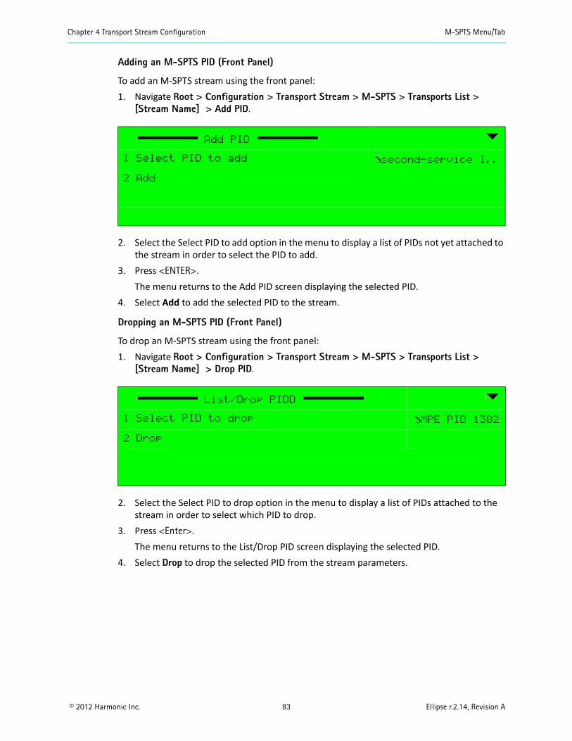
Chapter 4 Transport Stream Configuration M-SPTS Menu/Tab
© 2012 Harmonic Inc. 83 Ellipse r.2.14, Revision A
Adding an M-SPTS PID (Front Panel)
To add an M-SPTS stream using the front panel:1. Navigate Root > Configuration > Transport Stream > M-SPTS > Transports List >
[Stream Name] > Add PID.
2. Select the Select PID to add option in the menu to display a list of PIDs not yet attached to the stream in order to select the PID to add.
3. Press <ENTER>.The menu returns to the Add PID screen displaying the selected PID.
4. Select Add to add the selected PID to the stream.
Dropping an M-SPTS PID (Front Panel)
To drop an M-SPTS stream using the front panel:1. Navigate Root > Configuration > Transport Stream > M-SPTS > Transports List >
[Stream Name] > Drop PID.
2. Select the Select PID to drop option in the menu to display a list of PIDs attached to the stream in order to select which PID to drop.
3. Press <Enter>.The menu returns to the List/Drop PID screen displaying the selected PID.
4. Select Drop to drop the selected PID from the stream parameters.
Add PID
1 Select PID to add second-service I..
2 Add
List/Drop PIDD
1 Select PID to drop MPE PID 1382
2 Drop

Chapter 4 Transport Stream Configuration Services Menu
© 2012 Harmonic Inc. 84 Ellipse r.2.14, Revision A
Listing, Adding and Dropping an M-SPTS PID (Web Manager)
The stream PID parameters display in the Web Manager at the Transport > M-SPTS > [Stream Name] in the PID information area.
To select/drop a PID from the list provided: Mark/unmark the box next to the PID.
4.4 Services MenuThe Transport Stream Services Menu contains control tools for the services encoded in the transport stream and for managing the service configuration parameters. The information provided in this section is divided into the following subjects:
Service Management, which manages the services in the transport stream. Refer to 4.4.1 TS Service Management on page 85 for details.
Service Configuration Management, which manages the configuration of the service. Refer to 4.4.2 TS Service Configuration on page 88 for details.
Scrambling Management, which manages the scrambling of the service. Refer to 4.4.3 TS Scrambling Management on page 91for details.
Stream PID management, which manages the elementary streams in the service. Refer to 4.4.4 Add and Drop PID on page 98 for details.

Chapter 4 Transport Stream Configuration Services Menu
© 2012 Harmonic Inc. 85 Ellipse r.2.14, Revision A
4.4.1 TS Service Management
The Service management tools provided in the Transport Stream Service Menu enables displaying the list of available services, adding services and dropping services from the stream.
The available options are: Service List Menu – Lists the available services in the encoder (see 4.4.1.1 Listing Available
Services on page 85). Add Service Menu – Enables the user to create and add services to the encoder from the
transport stream (see 4.4.1.2 Adding a Service on page 86). Drop Service Menu – Enables the user to remove (drop) a service from the encoder (see
4.4.1.3 Drop a Service on page 87).
Front Panel
To access the Services menu on the front panel: Navigate Root > Configuration > Transport Stream > Services.
Web Manager
To access the Services menu in the Web Manager: Select Transport > Services.
4.4.1.1 Listing Available Services
The Service List menu displays a list of services defined for the transport streams.
NOTE: If the Service List is empty (in other words, there are no service defined for the stream), click the [Add New] button to add an entry.The Add Service Menu is displayed only when one or more unused channels are available.The number of available services is set according to license permission. The license permission can start from one service per video channel and up to 16 services per unit. The default value is set to 8 services.
Services
1 Service List
2 Add Service
3 Drop Service
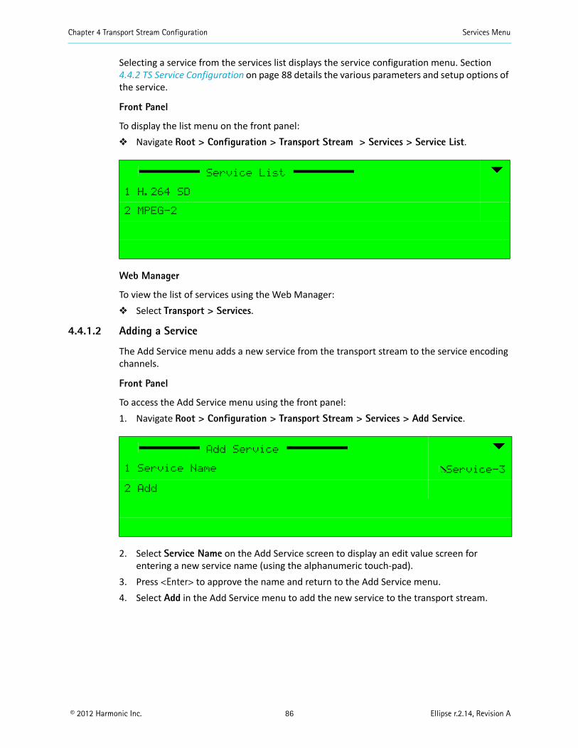
Chapter 4 Transport Stream Configuration Services Menu
© 2012 Harmonic Inc. 86 Ellipse r.2.14, Revision A
Selecting a service from the services list displays the service configuration menu. Section 4.4.2 TS Service Configuration on page 88 details the various parameters and setup options of the service.
Front Panel
To display the list menu on the front panel: Navigate Root > Configuration > Transport Stream > Services > Service List.
Web Manager
To view the list of services using the Web Manager: Select Transport > Services.
4.4.1.2 Adding a Service
The Add Service menu adds a new service from the transport stream to the service encoding channels.
Front Panel
To access the Add Service menu using the front panel:1. Navigate Root > Configuration > Transport Stream > Services > Add Service.
2. Select Service Name on the Add Service screen to display an edit value screen for entering a new service name (using the alphanumeric touch-pad).
3. Press <Enter> to approve the name and return to the Add Service menu. 4. Select Add in the Add Service menu to add the new service to the transport stream.
Service List
1 H.264 SD
2 MPEG-2
Add Service
1 Service Name Service-3
2 Add
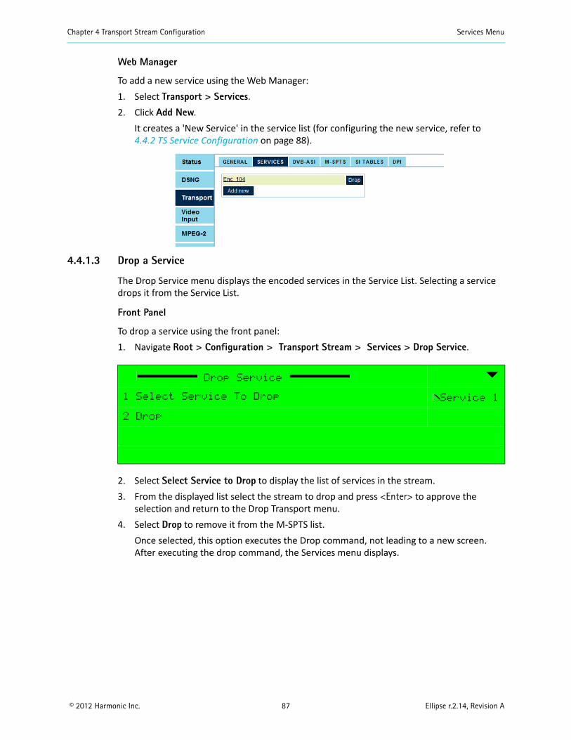
Chapter 4 Transport Stream Configuration Services Menu
© 2012 Harmonic Inc. 87 Ellipse r.2.14, Revision A
Web Manager
To add a new service using the Web Manager:1. Select Transport > Services.2. Click Add New.
It creates a 'New Service' in the service list (for configuring the new service, refer to 4.4.2 TS Service Configuration on page 88).
4.4.1.3 Drop a Service
The Drop Service menu displays the encoded services in the Service List. Selecting a service drops it from the Service List.
Front Panel
To drop a service using the front panel:1. Navigate Root > Configuration > Transport Stream > Services > Drop Service.
2. Select Select Service to Drop to display the list of services in the stream.3. From the displayed list select the stream to drop and press <Enter> to approve the
selection and return to the Drop Transport menu.4. Select Drop to remove it from the M-SPTS list.
Once selected, this option executes the Drop command, not leading to a new screen. After executing the drop command, the Services menu displays.
Drop Service
1 Select Service To Drop Service 1
2 Drop
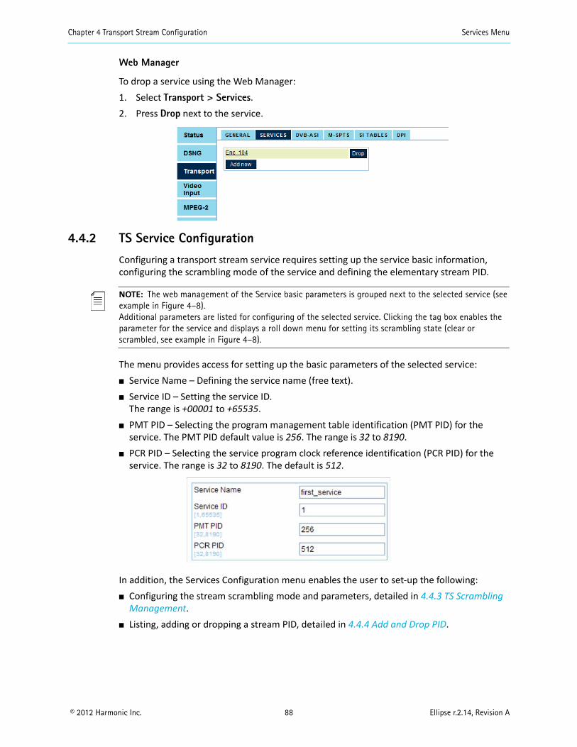
Chapter 4 Transport Stream Configuration Services Menu
© 2012 Harmonic Inc. 88 Ellipse r.2.14, Revision A
Web Manager
To drop a service using the Web Manager:1. Select Transport > Services.2. Press Drop next to the service.
4.4.2 TS Service Configuration
Configuring a transport stream service requires setting up the service basic information, configuring the scrambling mode of the service and defining the elementary stream PID.
NOTE: The web management of the Service basic parameters is grouped next to the selected service (see example in Figure 4–8). Additional parameters are listed for configuring of the selected service. Clicking the tag box enables the parameter for the service and displays a roll down menu for setting its scrambling state (clear or scrambled, see example in Figure 4–8).
The menu provides access for setting up the basic parameters of the selected service: Service Name – Defining the service name (free text). Service ID – Setting the service ID.
The range is +00001 to +65535. PMT PID – Selecting the program management table identification (PMT PID) for the
service. The PMT PID default value is 256. The range is 32 to 8190. PCR PID – Selecting the service program clock reference identification (PCR PID) for the
service. The range is 32 to 8190. The default is 512.
In addition, the Services Configuration menu enables the user to set-up the following: Configuring the stream scrambling mode and parameters, detailed in 4.4.3 TS Scrambling
Management. Listing, adding or dropping a stream PID, detailed in 4.4.4 Add and Drop PID.
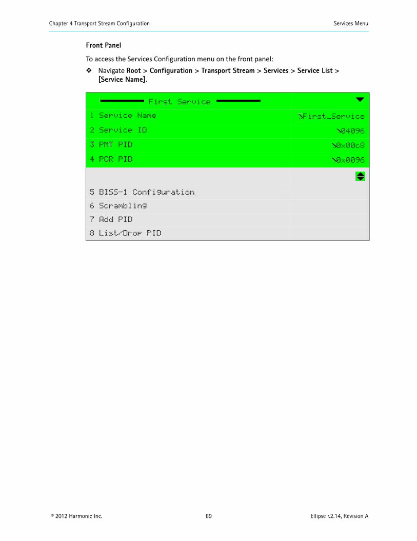
Chapter 4 Transport Stream Configuration Services Menu
© 2012 Harmonic Inc. 89 Ellipse r.2.14, Revision A
Front Panel
To access the Services Configuration menu on the front panel: Navigate Root > Configuration > Transport Stream > Services > Service List >
[Service Name].
First Service
1 Service Name First_Service
2 Service ID 04096
3 PMT PID 0x00c8
4 PCR PID 0x0096
5 BISS-1 Configuration
6 Scrambling
7 Add PID
8 List/Drop PID
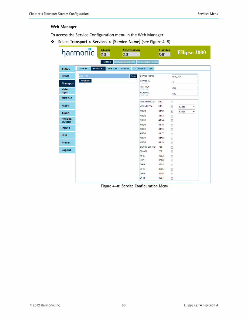
Chapter 4 Transport Stream Configuration Services Menu
© 2012 Harmonic Inc. 90 Ellipse r.2.14, Revision A
Web Manager
To access the Service Configuration menu in the Web Manager: Select Transport > Services > [Service Name] (see Figure 4–8).
Figure 4–8: Service Configuration Menu
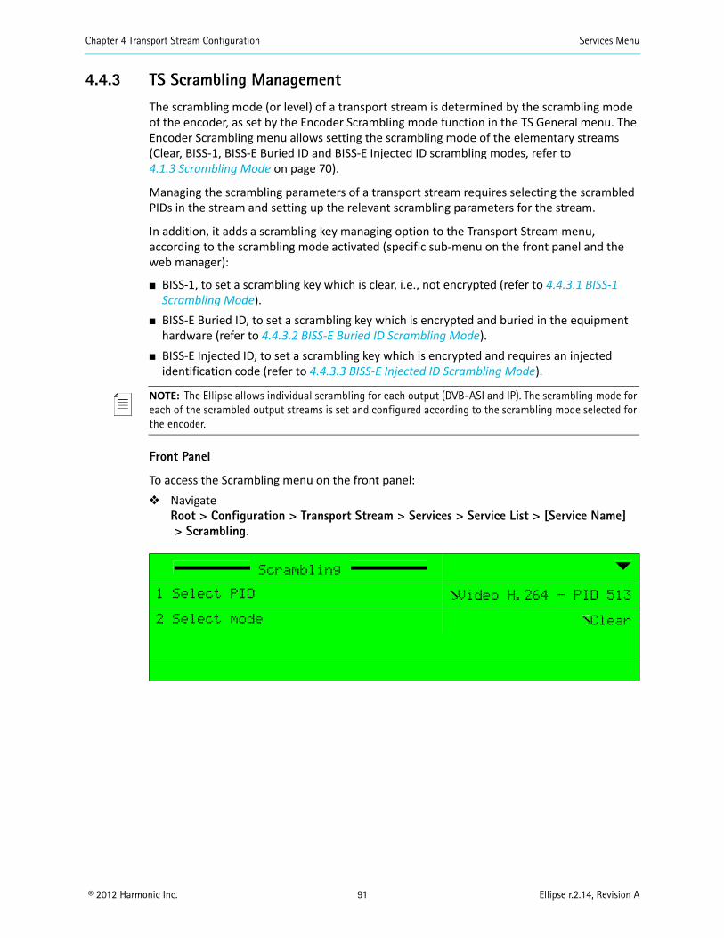
Chapter 4 Transport Stream Configuration Services Menu
© 2012 Harmonic Inc. 91 Ellipse r.2.14, Revision A
4.4.3 TS Scrambling Management
The scrambling mode (or level) of a transport stream is determined by the scrambling mode of the encoder, as set by the Encoder Scrambling mode function in the TS General menu. The Encoder Scrambling menu allows setting the scrambling mode of the elementary streams (Clear, BISS-1, BISS-E Buried ID and BISS-E Injected ID scrambling modes, refer to 4.1.3 Scrambling Mode on page 70).
Managing the scrambling parameters of a transport stream requires selecting the scrambled PIDs in the stream and setting up the relevant scrambling parameters for the stream.
In addition, it adds a scrambling key managing option to the Transport Stream menu, according to the scrambling mode activated (specific sub-menu on the front panel and the web manager):
BISS-1, to set a scrambling key which is clear, i.e., not encrypted (refer to 4.4.3.1 BISS-1 Scrambling Mode).
BISS-E Buried ID, to set a scrambling key which is encrypted and buried in the equipment hardware (refer to 4.4.3.2 BISS-E Buried ID Scrambling Mode).
BISS-E Injected ID, to set a scrambling key which is encrypted and requires an injected identification code (refer to 4.4.3.3 BISS-E Injected ID Scrambling Mode).
NOTE: The Ellipse allows individual scrambling for each output (DVB-ASI and IP). The scrambling mode for each of the scrambled output streams is set and configured according to the scrambling mode selected for the encoder.
Front Panel
To access the Scrambling menu on the front panel: Navigate
Root > Configuration > Transport Stream > Services > Service List > [Service Name]> Scrambling.
Scrambling
1 Select PID Video H.264 - PID 513
2 Select mode Clear

Chapter 4 Transport Stream Configuration Services Menu
© 2012 Harmonic Inc. 92 Ellipse r.2.14, Revision A
The 1. Select PID option allows selecting the elementary stream requested for setting its scrambling mode. The parameter displays a list of available elementary streams in the selected service. The available options appear as a list of currently-used elementary streams for the selected service. The list details the elementary stream's PID number.
Once the stream is selected, the 2. Select Mode option in the Scrambling Menu sets the scrambling mode for the selected elementary stream (Clear or Scrambled, see the following example).
Web Manager
To set the Clear Scrambling parameters using the Web Manager: Select Transport > Services > Service Name.
Select PID
1 ƒ Video H.264 - PID 513
2 ‚ AUD5 - PID 4116
Select mode
1 ƒ Clear
2 ‚ Scrambled
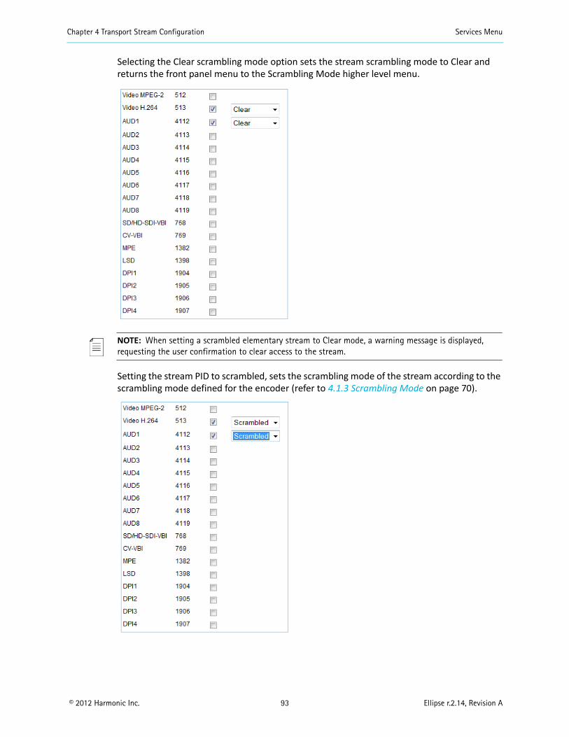
Chapter 4 Transport Stream Configuration Services Menu
© 2012 Harmonic Inc. 93 Ellipse r.2.14, Revision A
Selecting the Clear scrambling mode option sets the stream scrambling mode to Clear and returns the front panel menu to the Scrambling Mode higher level menu.
NOTE: When setting a scrambled elementary stream to Clear mode, a warning message is displayed, requesting the user confirmation to clear access to the stream.
Setting the stream PID to scrambled, sets the scrambling mode of the stream according to the scrambling mode defined for the encoder (refer to 4.1.3 Scrambling Mode on page 70).
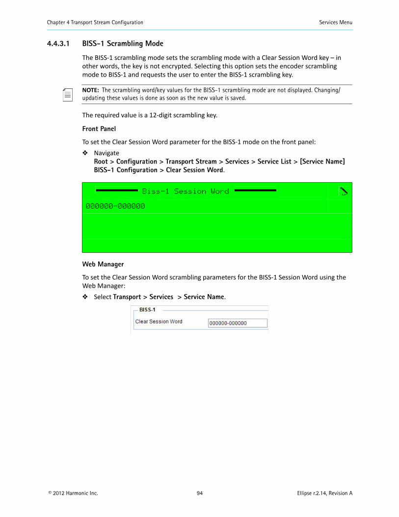
Chapter 4 Transport Stream Configuration Services Menu
© 2012 Harmonic Inc. 94 Ellipse r.2.14, Revision A
4.4.3.1 BISS-1 Scrambling Mode
The BISS-1 scrambling mode sets the scrambling mode with a Clear Session Word key – in other words, the key is not encrypted. Selecting this option sets the encoder scrambling mode to BISS-1 and requests the user to enter the BISS-1 scrambling key.
NOTE: The scrambling word/key values for the BISS-1 scrambling mode are not displayed. Changing/updating these values is done as soon as the new value is saved.
The required value is a 12-digit scrambling key.
Front Panel
To set the Clear Session Word parameter for the BISS-1 mode on the front panel: Navigate
Root > Configuration > Transport Stream > Services > Service List > [Service Name]BISS-1 Configuration > Clear Session Word.
Web Manager
To set the Clear Session Word scrambling parameters for the BISS-1 Session Word using the Web Manager: Select Transport > Services > Service Name.
Biss-1 Session Word
000000-000000
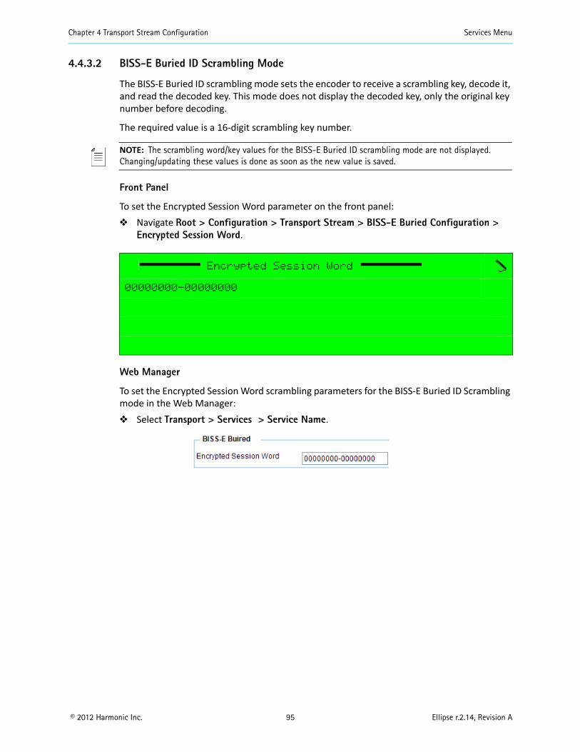
Chapter 4 Transport Stream Configuration Services Menu
© 2012 Harmonic Inc. 95 Ellipse r.2.14, Revision A
4.4.3.2 BISS-E Buried ID Scrambling Mode
The BISS-E Buried ID scrambling mode sets the encoder to receive a scrambling key, decode it, and read the decoded key. This mode does not display the decoded key, only the original key number before decoding.
The required value is a 16-digit scrambling key number.
NOTE: The scrambling word/key values for the BISS-E Buried ID scrambling mode are not displayed. Changing/updating these values is done as soon as the new value is saved.
Front Panel
To set the Encrypted Session Word parameter on the front panel: Navigate Root > Configuration > Transport Stream > BISS-E Buried Configuration >
Encrypted Session Word.
Web Manager
To set the Encrypted Session Word scrambling parameters for the BISS-E Buried ID Scrambling mode in the Web Manager: Select Transport > Services > Service Name.
Encrypted Session Word
00000000-00000000
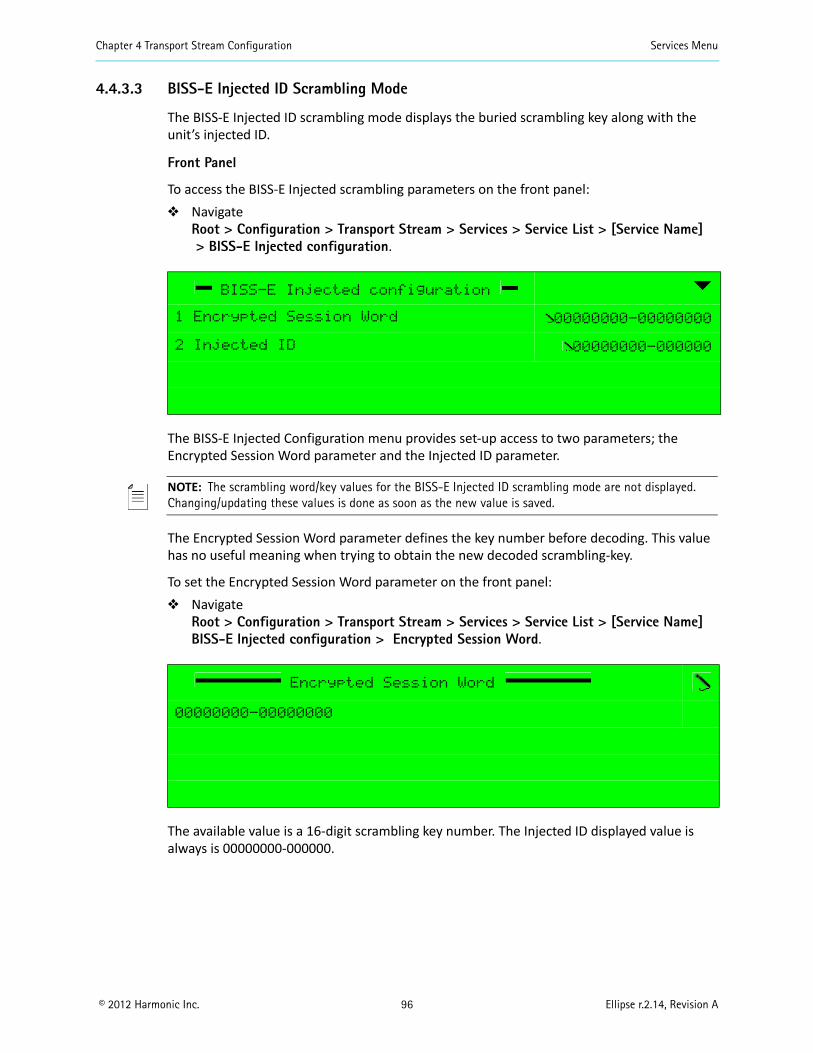
Chapter 4 Transport Stream Configuration Services Menu
© 2012 Harmonic Inc. 96 Ellipse r.2.14, Revision A
4.4.3.3 BISS-E Injected ID Scrambling Mode
The BISS-E Injected ID scrambling mode displays the buried scrambling key along with the unit’s injected ID.
Front Panel
To access the BISS-E Injected scrambling parameters on the front panel: Navigate
Root > Configuration > Transport Stream > Services > Service List > [Service Name]> BISS-E Injected configuration.
The BISS-E Injected Configuration menu provides set-up access to two parameters; the Encrypted Session Word parameter and the Injected ID parameter.
NOTE: The scrambling word/key values for the BISS-E Injected ID scrambling mode are not displayed. Changing/updating these values is done as soon as the new value is saved.
The Encrypted Session Word parameter defines the key number before decoding. This value has no useful meaning when trying to obtain the new decoded scrambling-key.
To set the Encrypted Session Word parameter on the front panel: Navigate
Root > Configuration > Transport Stream > Services > Service List > [Service Name]BISS-E Injected configuration > Encrypted Session Word.
The available value is a 16-digit scrambling key number. The Injected ID displayed value is always is 00000000-000000.
BISS-E Injected configuration
1 Encrypted Session Word 00000000-00000000
2 Injected ID 00000000-000000
Encrypted Session Word
00000000-00000000
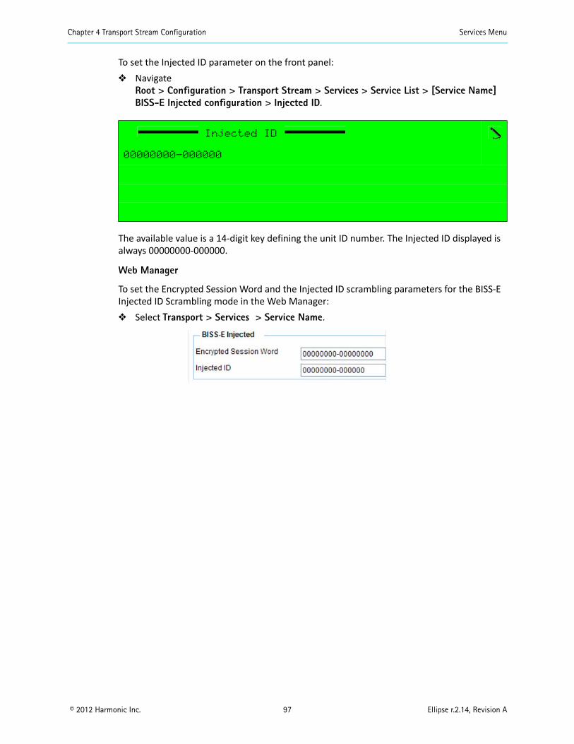
Chapter 4 Transport Stream Configuration Services Menu
© 2012 Harmonic Inc. 97 Ellipse r.2.14, Revision A
To set the Injected ID parameter on the front panel: Navigate
Root > Configuration > Transport Stream > Services > Service List > [Service Name]BISS-E Injected configuration > Injected ID.
The available value is a 14-digit key defining the unit ID number. The Injected ID displayed is always 00000000-000000.
Web Manager
To set the Encrypted Session Word and the Injected ID scrambling parameters for the BISS-E Injected ID Scrambling mode in the Web Manager: Select Transport > Services > Service Name.
Injected ID
00000000-000000
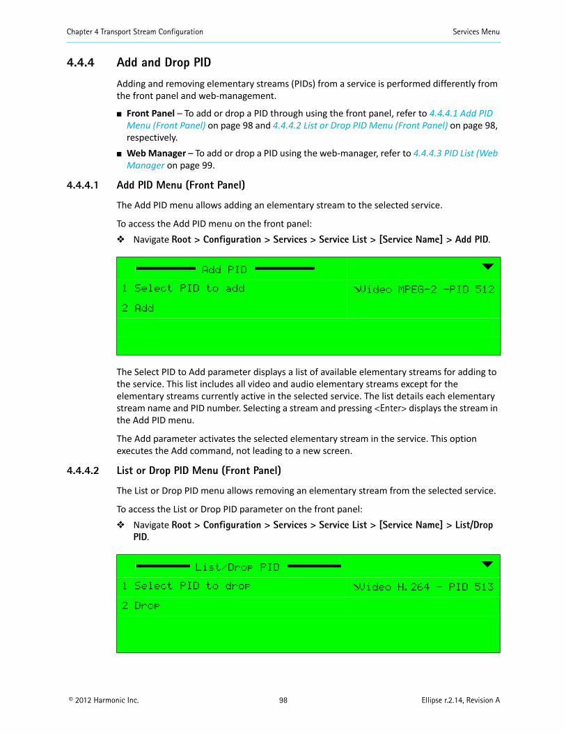
Chapter 4 Transport Stream Configuration Services Menu
© 2012 Harmonic Inc. 98 Ellipse r.2.14, Revision A
4.4.4 Add and Drop PID
Adding and removing elementary streams (PIDs) from a service is performed differently from the front panel and web-management.
Front Panel – To add or drop a PID through using the front panel, refer to 4.4.4.1 Add PID Menu (Front Panel) on page 98 and 4.4.4.2 List or Drop PID Menu (Front Panel) on page 98, respectively.
Web Manager – To add or drop a PID using the web-manager, refer to 4.4.4.3 PID List (Web Manager on page 99.
4.4.4.1 Add PID Menu (Front Panel)
The Add PID menu allows adding an elementary stream to the selected service.
To access the Add PID menu on the front panel: Navigate Root > Configuration > Services > Service List > [Service Name] > Add PID.
The Select PID to Add parameter displays a list of available elementary streams for adding to the service. This list includes all video and audio elementary streams except for the elementary streams currently active in the selected service. The list details each elementary stream name and PID number. Selecting a stream and pressing <Enter> displays the stream in the Add PID menu.
The Add parameter activates the selected elementary stream in the service. This option executes the Add command, not leading to a new screen.
4.4.4.2 List or Drop PID Menu (Front Panel)
The List or Drop PID menu allows removing an elementary stream from the selected service.
To access the List or Drop PID parameter on the front panel: Navigate Root > Configuration > Services > Service List > [Service Name] > List/Drop
PID.
Add PID
1 Select PID to add Video MPEG-2 -PID 512
2 Add
List/Drop PID
1 Select PID to drop Video H.264 - PID 513
2 Drop
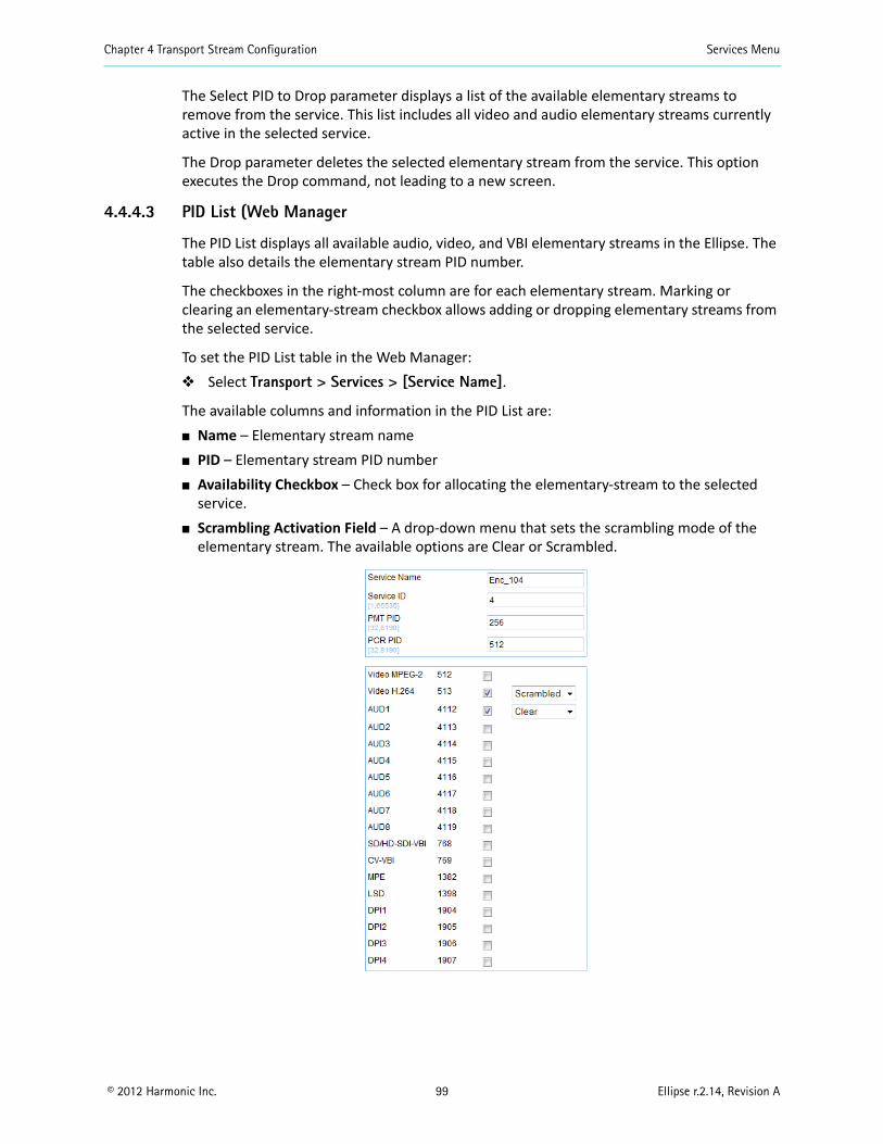
Chapter 4 Transport Stream Configuration Services Menu
© 2012 Harmonic Inc. 99 Ellipse r.2.14, Revision A
The Select PID to Drop parameter displays a list of the available elementary streams to remove from the service. This list includes all video and audio elementary streams currently active in the selected service.
The Drop parameter deletes the selected elementary stream from the service. This option executes the Drop command, not leading to a new screen.
4.4.4.3 PID List (Web Manager
The PID List displays all available audio, video, and VBI elementary streams in the Ellipse. The table also details the elementary stream PID number.
The checkboxes in the right-most column are for each elementary stream. Marking or clearing an elementary-stream checkbox allows adding or dropping elementary streams from the selected service.
To set the PID List table in the Web Manager: Select Transport > Services > [Service Name].
The available columns and information in the PID List are: Name – Elementary stream name PID – Elementary stream PID number Availability Checkbox – Check box for allocating the elementary-stream to the selected
service. Scrambling Activation Field – A drop-down menu that sets the scrambling mode of the
elementary stream. The available options are Clear or Scrambled.
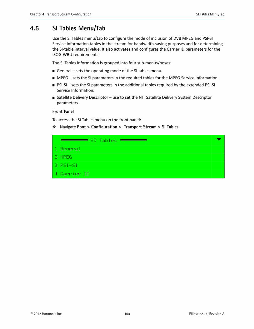
Chapter 4 Transport Stream Configuration SI Tables Menu/Tab
© 2012 Harmonic Inc. 100 Ellipse r.2.14, Revision A
4.5 SI Tables Menu/TabUse the SI Tables menu/tab to configure the mode of inclusion of DVB MPEG and PSI-SI Service Information tables in the stream for bandwidth-saving purposes and for determining the SI-table interval value. It also activates and configures the Carrier ID parameters for the ISOG-WBU requirements.
The SI Tables information is grouped into four sub-menus/boxes:
General – sets the operating mode of the SI tables menu. MPEG – sets the SI parameters in the required tables for the MPEG Service Information. PSI-SI – sets the SI parameters in the additional tables required by the extended PSI-SI
Service Information. Satellite Delivery Descriptor – use to set the NIT Satellite Delivery System Descriptor
parameters.
Front Panel
To access the SI Tables menu on the front panel: Navigate Root > Configuration > Transport Stream > SI Tables.
SI Tables
1 General
2 MPEG
3 PSI-SI
4 Carrier ID
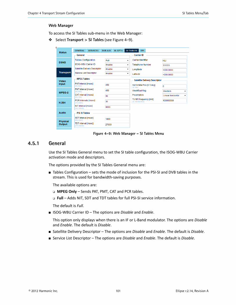
Chapter 4 Transport Stream Configuration SI Tables Menu/Tab
© 2012 Harmonic Inc. 101 Ellipse r.2.14, Revision A
Web Manager
To access the SI Tables sub-menu in the Web Manager: Select Transport > SI Tables (see Figure 4–9).
Figure 4–9: Web Manager – SI Tables Menu
4.5.1 General
Use the SI Tables General menu to set the SI table configuration, the ISOG-WBU Carrier activation mode and descriptors.
The options provided by the SI Tables General menu are:
Tables Configuration – sets the mode of inclusion for the PSI-SI and DVB tables in the stream. This is used for bandwidth-saving purposes.
The available options are: MPEG Only – Sends PAT, PMT, CAT and PCR tables. Full – Adds NIT, SDT and TDT tables for full PSI-SI service information.
The default is Full. ISOG-WBU Carrier ID – The options are Disable and Enable.
This option only displays when there is an IF or L-Band modulator. The options are Disable and Enable. The default is Disable.
Satellite Delivery Descriptor – The options are Disable and Enable. The default is Disable. Service List Descriptor – The options are Disable and Enable. The default is Disable.
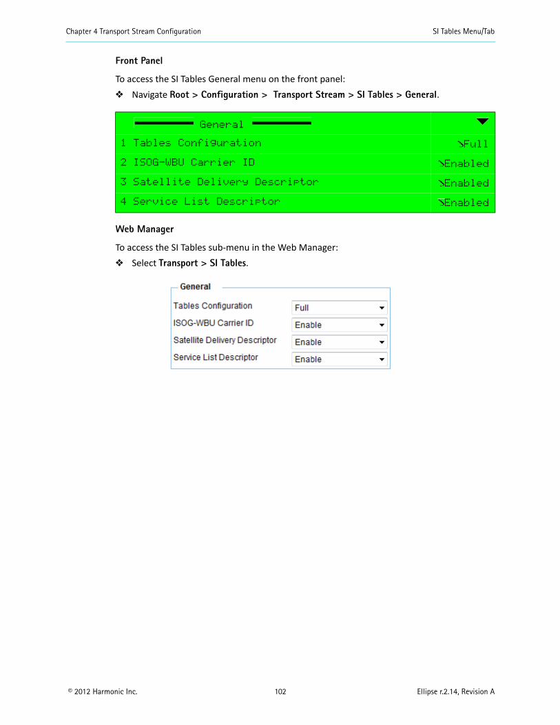
Chapter 4 Transport Stream Configuration SI Tables Menu/Tab
© 2012 Harmonic Inc. 102 Ellipse r.2.14, Revision A
Front Panel
To access the SI Tables General menu on the front panel: Navigate Root > Configuration > Transport Stream > SI Tables > General.
Web Manager
To access the SI Tables sub-menu in the Web Manager: Select Transport > SI Tables.
General
1 Tables Configuration Full
2 ISOG-WBU Carrier ID Enabled
3 Satellite Delivery Descriptor Enabled
4 Service List Descriptor Enabled
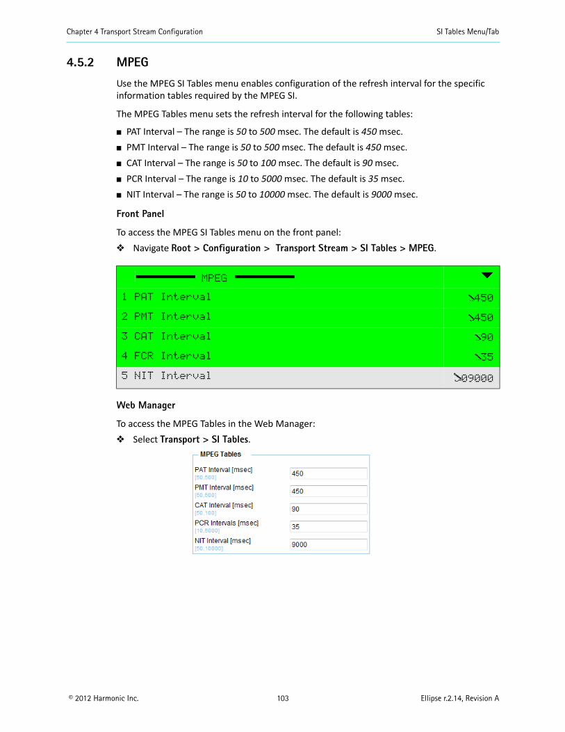
Chapter 4 Transport Stream Configuration SI Tables Menu/Tab
© 2012 Harmonic Inc. 103 Ellipse r.2.14, Revision A
4.5.2 MPEG
Use the MPEG SI Tables menu enables configuration of the refresh interval for the specific information tables required by the MPEG SI.
The MPEG Tables menu sets the refresh interval for the following tables:
PAT Interval – The range is 50 to 500 msec. The default is 450 msec. PMT Interval – The range is 50 to 500 msec. The default is 450 msec. CAT Interval – The range is 50 to 100 msec. The default is 90 msec. PCR Interval – The range is 10 to 5000 msec. The default is 35 msec. NIT Interval – The range is 50 to 10000 msec. The default is 9000 msec.
Front Panel
To access the MPEG SI Tables menu on the front panel: Navigate Root > Configuration > Transport Stream > SI Tables > MPEG.
Web Manager
To access the MPEG Tables in the Web Manager: Select Transport > SI Tables.
MPEG
1 PAT Interval 450
2 PMT Interval 450
3 CAT Interval 90
4 FCR Interval 35
5 NIT Interval 09000
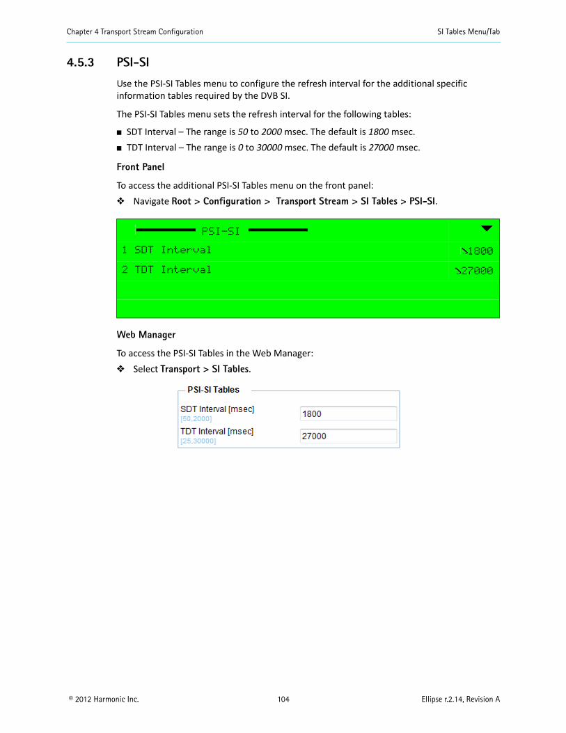
Chapter 4 Transport Stream Configuration SI Tables Menu/Tab
© 2012 Harmonic Inc. 104 Ellipse r.2.14, Revision A
4.5.3 PSI-SI
Use the PSI-SI Tables menu to configure the refresh interval for the additional specific information tables required by the DVB SI.
The PSI-SI Tables menu sets the refresh interval for the following tables:
SDT Interval – The range is 50 to 2000 msec. The default is 1800 msec. TDT Interval – The range is 0 to 30000 msec. The default is 27000 msec.
Front Panel
To access the additional PSI-SI Tables menu on the front panel: Navigate Root > Configuration > Transport Stream > SI Tables > PSI-SI.
Web Manager
To access the PSI-SI Tables in the Web Manager: Select Transport > SI Tables.
PSI-SI
1 SDT Interval 1800
2 TDT Interval 27000
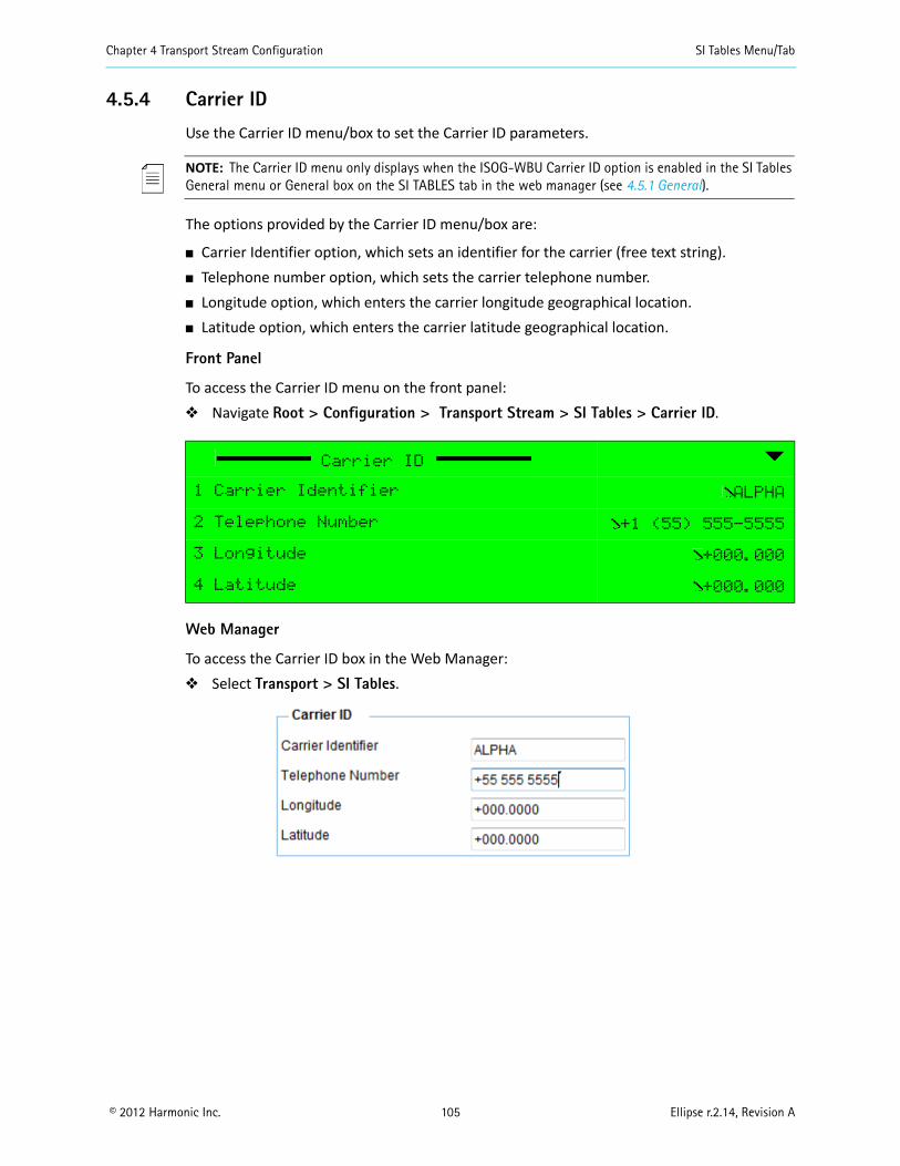
Chapter 4 Transport Stream Configuration SI Tables Menu/Tab
© 2012 Harmonic Inc. 105 Ellipse r.2.14, Revision A
4.5.4 Carrier ID
Use the Carrier ID menu/box to set the Carrier ID parameters.
NOTE: The Carrier ID menu only displays when the ISOG-WBU Carrier ID option is enabled in the SI Tables General menu or General box on the SI TABLES tab in the web manager (see 4.5.1 General).
The options provided by the Carrier ID menu/box are:
Carrier Identifier option, which sets an identifier for the carrier (free text string). Telephone number option, which sets the carrier telephone number. Longitude option, which enters the carrier longitude geographical location. Latitude option, which enters the carrier latitude geographical location.
Front Panel
To access the Carrier ID menu on the front panel: Navigate Root > Configuration > Transport Stream > SI Tables > Carrier ID.
Web Manager
To access the Carrier ID box in the Web Manager: Select Transport > SI Tables.
Carrier ID
1 Carrier Identifier ALPHA
2 Telephone Number +1 (55) 555-5555
3 Longitude +000.000
4 Latitude +000.000
Chapter 4 Transport Stream Configuration SI Tables Menu/Tab
© 2012 Harmonic Inc. 106 Ellipse r.2.14, Revision A
4.5.5 Satellite Delivery Descriptor
Use the Satellite Delivery Descriptor menu/box to set the NIT Satellite Delivery System Descriptor parameters.
NOTE: This menu/box only displays on the Ellipse 2000.
The options provided by the Satellite Delivery Descriptor are:
Sat Orbital Pos – The range is 0 to 180. The default is 0. West/East flag – The default is Western. Polarization – The options are: Linear-horizontal, Linear-vertical, Circular-left, Circular-
right. The default is Linear-horizontal. TX RF Frequency – this option must be set if there is an IF modulator. – The range is 0 to
00000000. The default is 950000.
Front Panel
To access the Satellite Delivery Descriptor menu on the front panel: Navigate Root > Configuration > Transport Stream > SI Tables >
Satellite Delivery Descriptor.
Web Manager
To access the Satellite Delivery Descriptor box in the Web Manager: Select Transport > SI Tables.
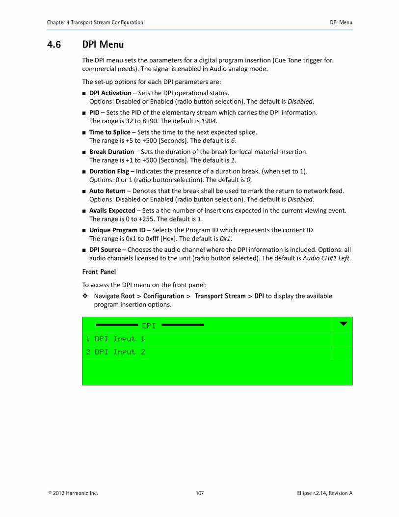
Chapter 4 Transport Stream Configuration DPI Menu
© 2012 Harmonic Inc. 107 Ellipse r.2.14, Revision A
4.6 DPI MenuThe DPI menu sets the parameters for a digital program insertion (Cue Tone trigger for commercial needs). The signal is enabled in Audio analog mode.
The set-up options for each DPI parameters are: DPI Activation – Sets the DPI operational status.
Options: Disabled or Enabled (radio button selection). The default is Disabled. PID – Sets the PID of the elementary stream which carries the DPI information.
The range is 32 to 8190. The default is 1904. Time to Splice – Sets the time to the next expected splice.
The range is +5 to +500 [Seconds]. The default is 6. Break Duration – Sets the duration of the break for local material insertion.
The range is +1 to +500 [Seconds]. The default is 1. Duration Flag – Indicates the presence of a duration break. (when set to 1).
Options: 0 or 1 (radio button selection). The default is 0. Auto Return – Denotes that the break shall be used to mark the return to network feed.
Options: Disabled or Enabled (radio button selection). The default is Disabled. Avails Expected – Sets a the number of insertions expected in the current viewing event.
The range is 0 to +255. The default is 1. Unique Program ID – Selects the Program ID which represents the content ID.
The range is 0x1 to 0xfff [Hex]. The default is 0x1. DPI Source – Chooses the audio channel where the DPI information is included. Options: all
audio channels licensed to the unit (radio button selected). The default is Audio CH#1 Left.
Front Panel
To access the DPI menu on the front panel: Navigate Root > Configuration > Transport Stream > DPI to display the available
program insertion options.
DPI
1 DPI Input 1
2 DPI Input 2
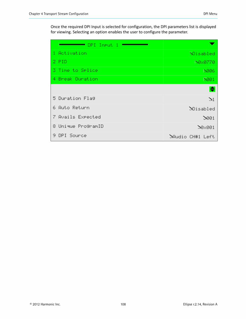
Chapter 4 Transport Stream Configuration DPI Menu
© 2012 Harmonic Inc. 108 Ellipse r.2.14, Revision A
Once the required DPI Input is selected for configuration, the DPI parameters list is displayed for viewing. Selecting an option enables the user to configure the parameter.
DPI Input 1
1 Activation Disabled
2 PID 0x0770
3 Time to Splice 006
4 Break Duration 001
5 Duration Flag 1
6 Auto Return Disabled
7 Avails Expected 001
8 Unique ProgramID 0x001
9 DPI Source Audio CH#1 Left
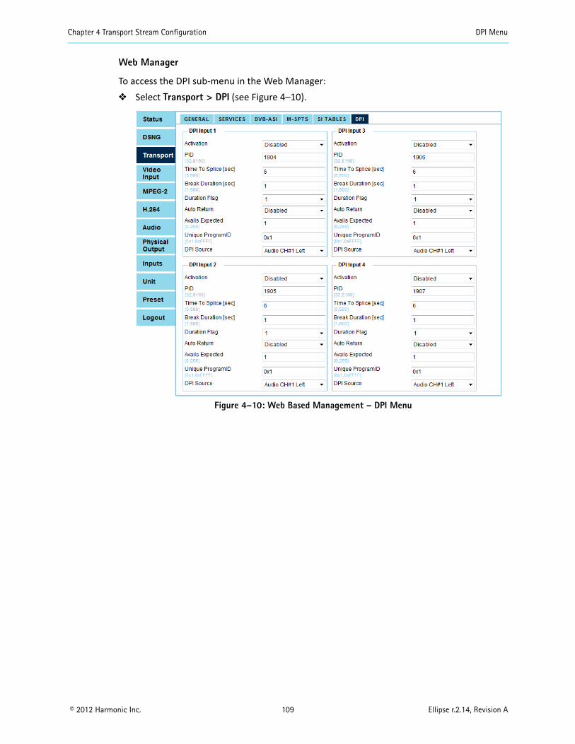
Chapter 4 Transport Stream Configuration DPI Menu
© 2012 Harmonic Inc. 109 Ellipse r.2.14, Revision A
Web Manager
To access the DPI sub-menu in the Web Manager: Select Transport > DPI (see Figure 4–10).
Figure 4–10: Web Based Management – DPI Menu
© 2012 Harmonic Inc. 110 Ellipse r.2.14, Revision A
Chapter 5Video Configuration
Use the following three menus/tabs to configure the Ellipse encoder for the video data received (input) and generated (output).
Video Input MPEG-2 H.264
The Ellipse 1000/2000 Encoders have SD/HD-SDI and CV video inputs and SD MPEG-2 and SD/HD MPEG-4 AVC engines.
The main sections are: 5.1 Video Input 5.2 Video Engine
If your Ellipse was shipped before release 2.9 then consult a pre-release 2.9 Ellipse Installation Guide for video input types (CV, SDI) and quantities. The Analog Interface options are only available for CV inputs. The video engine type for the Ellipse Contribution Encoders is either MPEG-2 or MPEG-4 AVC (H.264).
See Figure 5–1 for the front panel video configuration menu tree structure.
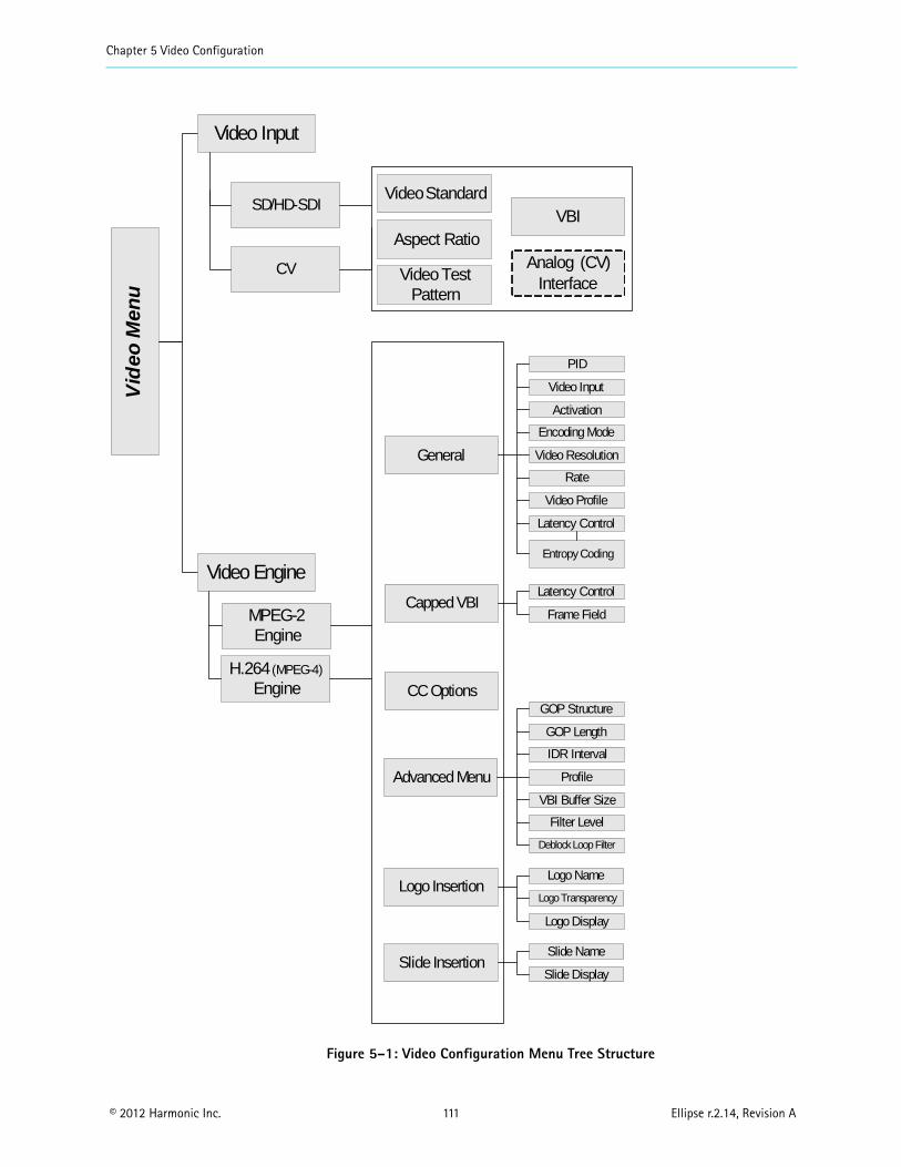
Chapter 5 Video Configuration
© 2012 Harmonic Inc. 111 Ellipse r.2.14, Revision A
Figure 5–1: Video Configuration Menu Tree Structure
Vid
eo M
enu
SD/HD-SDI
Video Test Pattern
VideoStandard
PID
Video Input
Aspect RatioVBI
Analog (CV) Interface
Activation
Encoding Mode
Video Resolution
Rate
Entropy Coding
Latency Control
Video Input
Capped VBI
Video Engine
Video Profile
General
Advanced Menu
Frame Field
Latency Control
GOP Structure
GOP Length
IDR Interval
Profile
VBI Buffer Size
Filter Level
Deblock Loop Filter
Logo InsertionLogo Transparency
Logo Name
Slide InsertionSlide Display
Slide Name
Logo Display
MPEG-2Engine
H.264(MPEG-4)
Engine
CV
CC Options

Chapter 5 Video Configuration Video Input
© 2012 Harmonic Inc. 112 Ellipse r.2.14, Revision A
5.1 Video InputThe Video Input menu displays the available video-channels in the Ellipse.
The Ellipse 1000/2000 encoder supports two types of video input interfaces:
SD/HD-SDI (Serial Digital Interface) CV (Composite Video)
Each input interface comprises different parameters, according to its interface card capabilities.
The SDI parameters are:
Video Standard (SDI and CV Video Inputs)
Video Test Pattern
Aspect Ratio
VBI
The CV parameters are:
Video Standard (SDI and CV Video Inputs)
Video Test Pattern
Aspect Ratio
VBI
Analog Interface
See sections 5.1.1 – 5.1.5 for parameter descriptions.
The CV Input sub-menu/sub-tab displays a list of video channels, categorized by a number and interface type (the web manager displays a row of sub-tabs with the video-channel names, and the first channel is selected automatically). Select a video channel from the list to display the channel’s configuration parameters (related to its input interface).
Front Panel
To access the Video Input menu using the front panel: Navigate Root > Configuration > Video > Video Input.
Video Input
1 SD/HD-SDI
2 CV
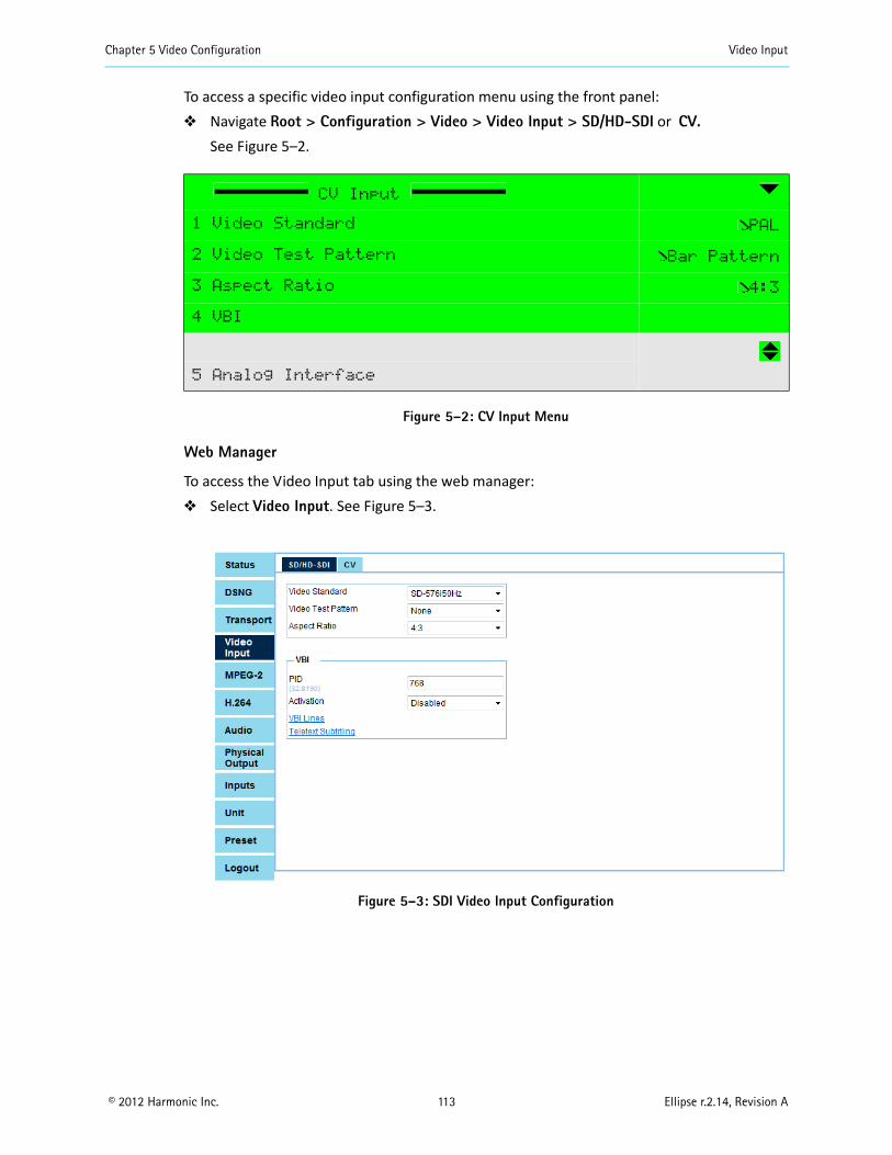
Chapter 5 Video Configuration Video Input
© 2012 Harmonic Inc. 113 Ellipse r.2.14, Revision A
To access a specific video input configuration menu using the front panel: Navigate Root > Configuration > Video > Video Input > SD/HD-SDI or CV.
See Figure 5–2.
Figure 5–2: CV Input Menu
Web Manager
To access the Video Input tab using the web manager: Select Video Input. See Figure 5–3.
Figure 5–3: SDI Video Input Configuration
CV Input
1 Video Standard PAL
2 Video Test Pattern Bar Pattern
3 Aspect Ratio 4:3
4 VBI
5 Analog Interface

Chapter 5 Video Configuration Video Input
© 2012 Harmonic Inc. 114 Ellipse r.2.14, Revision A
Figure 5–4: Composite Video Input Configuration
5.1.1 Video Standard (SDI and CV Video Inputs)
The Video Standard parameter displays and manages the current video format for the video interface and video encoding for the video input received by the Ellipse 1000/2000 over the SD/HD-SDI (digital) and CV (analog) interface. It sets the format of the video channel inputs.
NOTE: When you set the Video Standard to Auto, you must also set the engine’s Video Horizontal Resolution to Auto.
The CV Video Standard options are:
The CV Video Standard default is PAL.
NOTE: When set to Auto Format, the unit automatically tries to change the format according to the stream.If any video definition does not match the new format, the encoder does not change the format (for example, VBI lines or a resolution that is available only for NTSC).The encoder displays a Dependency Check error message and maintains the previous video format; the user must set all values to suit the new format and then automatic setting can be performed.
Auto Format Automatically detects the stream’s format (PAL or NTSC) and changes accordingly
PAL
NTSC
PAL M
PAL CN Sets the required format
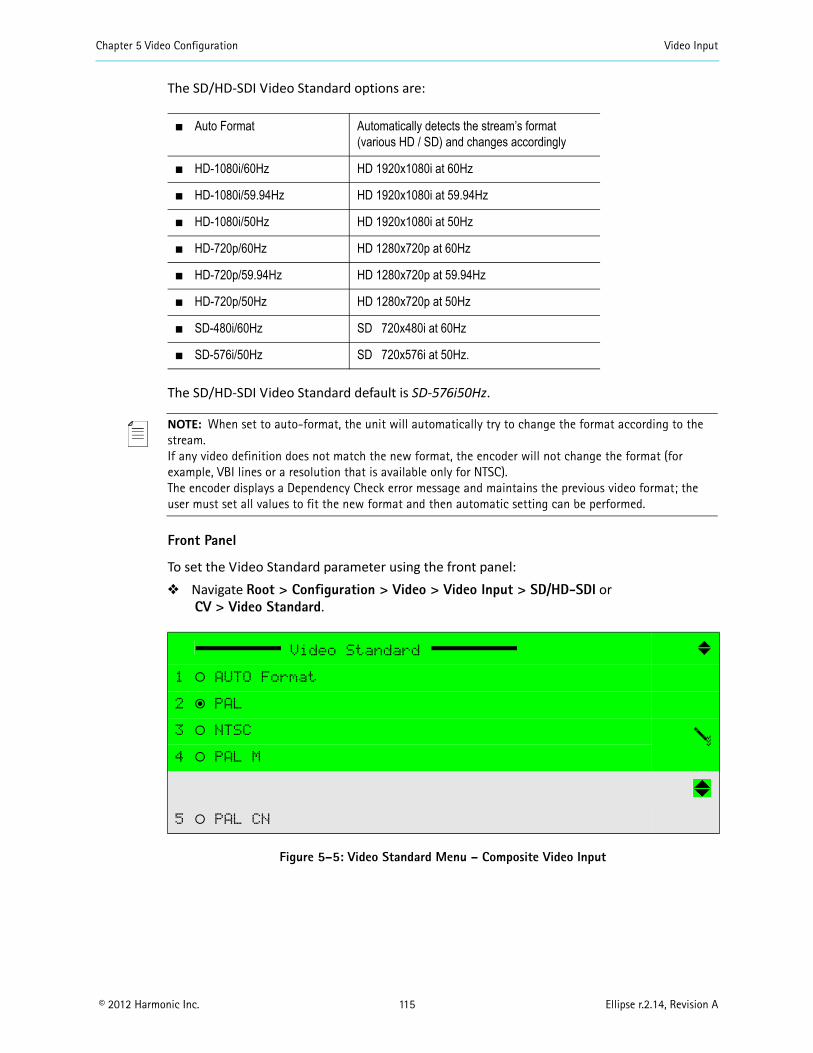
Chapter 5 Video Configuration Video Input
© 2012 Harmonic Inc. 115 Ellipse r.2.14, Revision A
The SD/HD-SDI Video Standard options are:
The SD/HD-SDI Video Standard default is SD-576i50Hz.
NOTE: When set to auto-format, the unit will automatically try to change the format according to the stream.If any video definition does not match the new format, the encoder will not change the format (for example, VBI lines or a resolution that is available only for NTSC).The encoder displays a Dependency Check error message and maintains the previous video format; the user must set all values to fit the new format and then automatic setting can be performed.
Front Panel
To set the Video Standard parameter using the front panel: Navigate Root > Configuration > Video > Video Input > SD/HD-SDI or
CV > Video Standard.
Figure 5–5: Video Standard Menu – Composite Video Input
Auto Format Automatically detects the stream’s format (various HD / SD) and changes accordingly
HD-1080i/60Hz HD 1920x1080i at 60Hz
HD-1080i/59.94Hz HD 1920x1080i at 59.94Hz
HD-1080i/50Hz HD 1920x1080i at 50Hz
HD-720p/60Hz HD 1280x720p at 60Hz
HD-720p/59.94Hz HD 1280x720p at 59.94Hz
HD-720p/50Hz HD 1280x720p at 50Hz
SD-480i/60Hz SD 720x480i at 60Hz
SD-576i/50Hz SD 720x576i at 50Hz.
Video Standard
1 ‚ AUTO Format
2 ƒ PAL
3 ‚ NTSC
4 ‚ PAL M
5 ‚ PAL CN
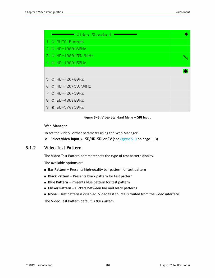
Chapter 5 Video Configuration Video Input
© 2012 Harmonic Inc. 116 Ellipse r.2.14, Revision A
Figure 5–6: Video Standard Menu – SDI Input
Web Manager
To set the Video Format parameter using the Web Manager: Select Video Input > SD/HD-SDI or CV (see Figure 5–3 on page 113).
5.1.2 Video Test Pattern
The Video Test Pattern parameter sets the type of test pattern display.
The available options are:
Bar Pattern – Presents high-quality bar pattern for test pattern
Black Pattern – Presents black pattern for test pattern Blue Pattern – Presents blue pattern for test pattern Flicker Pattern – Flickers between bar and black patterns None – Test pattern is disabled. Video test source is routed from the video interface.
The Video Test Pattern default is Bar Pattern.
Video Standard
1 ‚ AUTO Format
2 ‚ HD-1080i60Hz
3 ‚ HD-1080i59.94Hz
4 ‚ HD-1080i50Hz
5 ‚ HD-720p60Hz
6 ‚ HD-720p59.94Hz
7 ‚ HD-720p50Hz
8 ‚ SD-480i60Hz
9 ƒ SD-576i50Hz
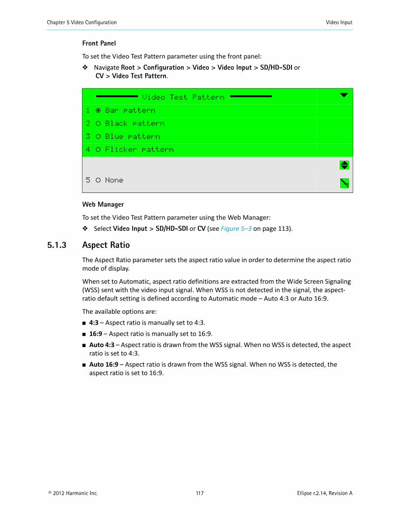
Chapter 5 Video Configuration Video Input
© 2012 Harmonic Inc. 117 Ellipse r.2.14, Revision A
Front Panel
To set the Video Test Pattern parameter using the front panel: Navigate Root > Configuration > Video > Video Input > SD/HD-SDI or
CV > Video Test Pattern.
Web Manager
To set the Video Test Pattern parameter using the Web Manager: Select Video Input > SD/HD-SDI or CV (see Figure 5–3 on page 113).
5.1.3 Aspect Ratio
The Aspect Ratio parameter sets the aspect ratio value in order to determine the aspect ratio mode of display.
When set to Automatic, aspect ratio definitions are extracted from the Wide Screen Signaling (WSS) sent with the video input signal. When WSS is not detected in the signal, the aspect-ratio default setting is defined according to Automatic mode – Auto 4:3 or Auto 16:9.
The available options are: 4:3 – Aspect ratio is manually set to 4:3. 16:9 – Aspect ratio is manually set to 16:9. Auto 4:3 – Aspect ratio is drawn from the WSS signal. When no WSS is detected, the aspect
ratio is set to 4:3. Auto 16:9 – Aspect ratio is drawn from the WSS signal. When no WSS is detected, the
aspect ratio is set to 16:9.
Video Test Pattern
1 ƒ Bar pattern
2 ‚ Black pattern
3 ‚ Blue pattern
4 ‚ Flicker pattern
5 ‚ None
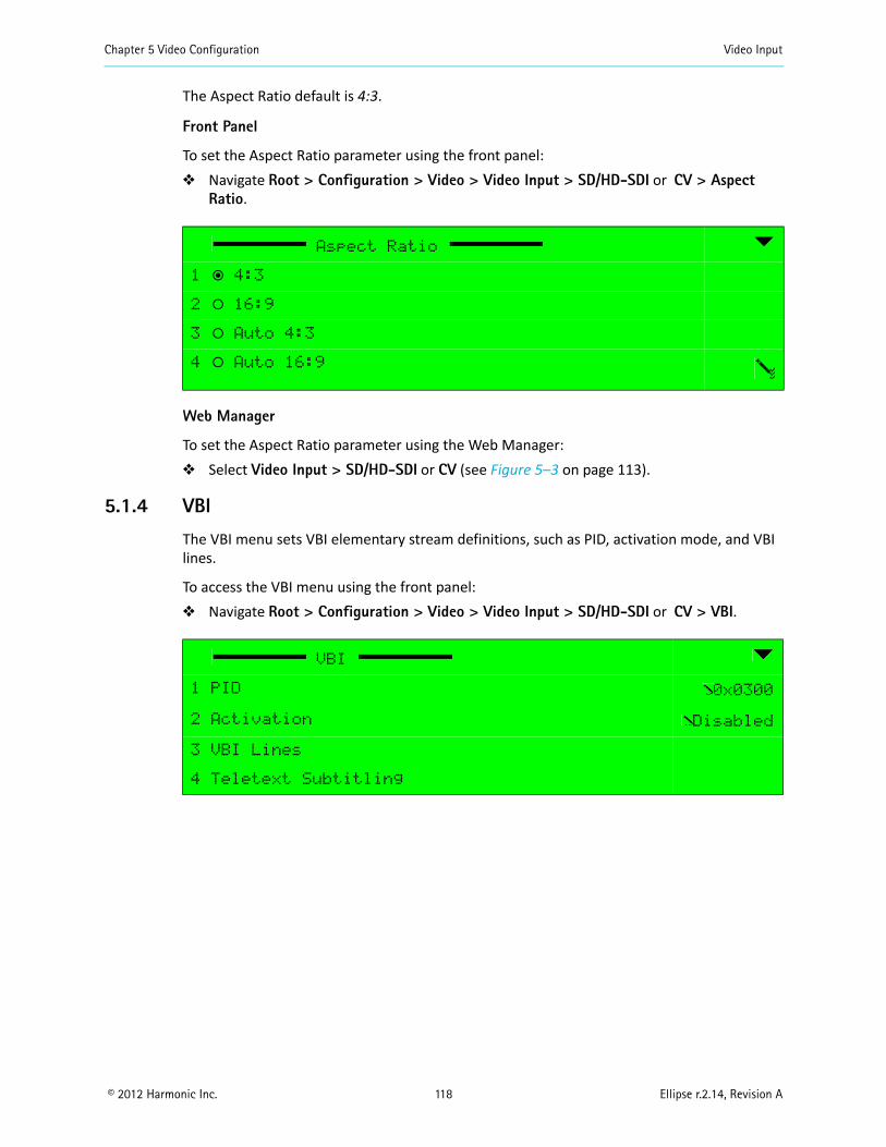
Chapter 5 Video Configuration Video Input
© 2012 Harmonic Inc. 118 Ellipse r.2.14, Revision A
The Aspect Ratio default is 4:3.
Front Panel
To set the Aspect Ratio parameter using the front panel: Navigate Root > Configuration > Video > Video Input > SD/HD-SDI or CV > Aspect
Ratio.
Web Manager
To set the Aspect Ratio parameter using the Web Manager: Select Video Input > SD/HD-SDI or CV (see Figure 5–3 on page 113).
5.1.4 VBI
The VBI menu sets VBI elementary stream definitions, such as PID, activation mode, and VBI lines.
To access the VBI menu using the front panel: Navigate Root > Configuration > Video > Video Input > SD/HD-SDI or CV > VBI.
Aspect Ratio
1 ƒ 4:3
2 ‚ 16:9
3 ‚ Auto 4:3
4 ‚ Auto 16:9
VBI
1 PID 0x0300
2 Activation Disabled
3 VBI Lines
4 Teletext Subtitling
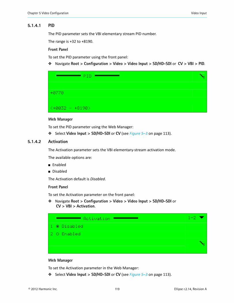
Chapter 5 Video Configuration Video Input
© 2012 Harmonic Inc. 119 Ellipse r.2.14, Revision A
5.1.4.1 PID
The PID parameter sets the VBI elementary stream PID number.
The range is +32 to +8190.
Front Panel
To set the PID parameter using the front panel: Navigate Root > Configuration > Video > Video Input > SD/HD-SDI or CV > VBI > PID.
Web Manager
To set the PID parameter using the Web Manager: Select Video Input > SD/HD-SDI or CV (see Figure 5–3 on page 113).
5.1.4.2 Activation
The Activation parameter sets the VBI elementary-stream activation mode.
The available options are:
Enabled Disabled
The Activation default is Disabled.
Front Panel
To set the Activation parameter on the front panel: Navigate Root > Configuration > Video > Video Input > SD/HD-SDI or
CV > VBI > Activation.
Web Manager
To set the Activation parameter in the Web Manager: Select Video Input > SD/HD-SDI or CV (see Figure 5–3 on page 113).
PID
+0770
<+0032 - +8190>
Activation 1-2
1 ƒ Disabled
2 ‚ Enabled
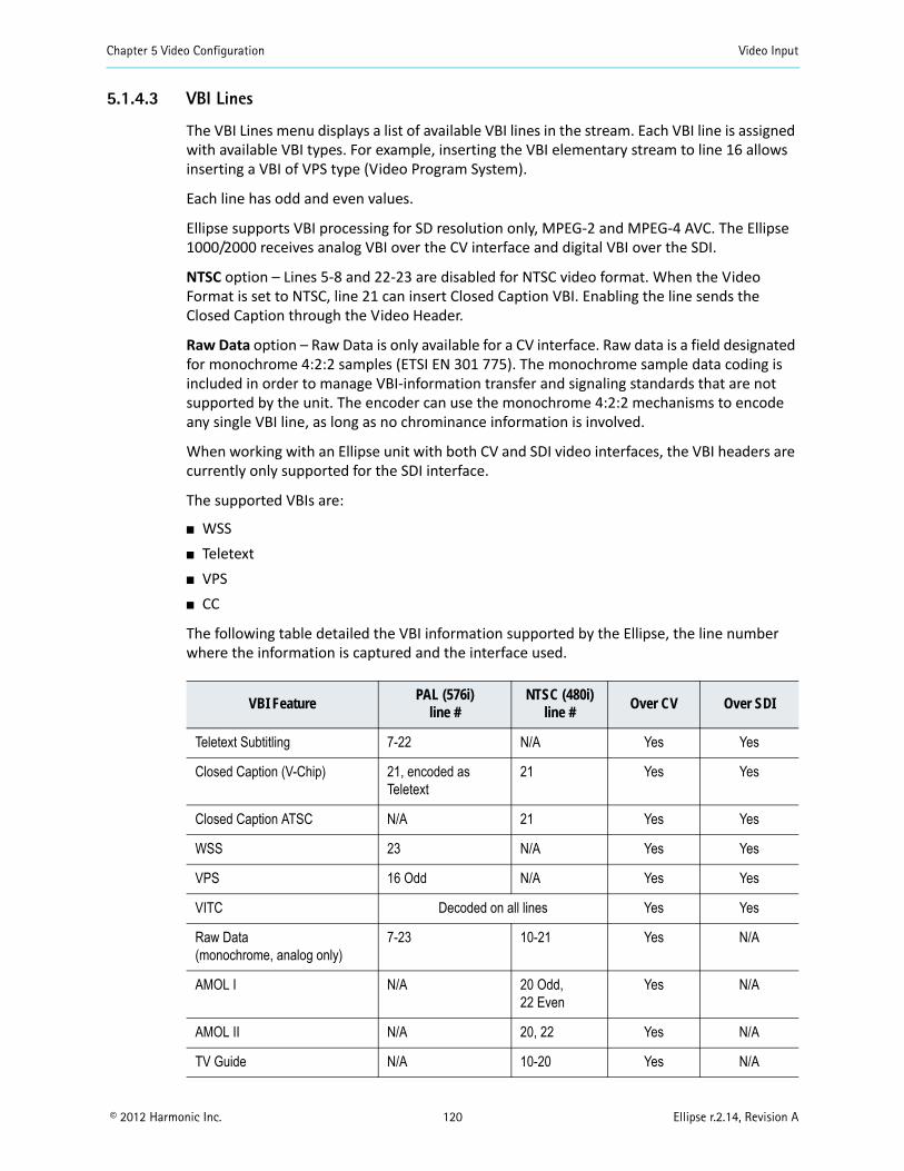
Chapter 5 Video Configuration Video Input
© 2012 Harmonic Inc. 120 Ellipse r.2.14, Revision A
5.1.4.3 VBI Lines
The VBI Lines menu displays a list of available VBI lines in the stream. Each VBI line is assigned with available VBI types. For example, inserting the VBI elementary stream to line 16 allows inserting a VBI of VPS type (Video Program System).
Each line has odd and even values.
Ellipse supports VBI processing for SD resolution only, MPEG-2 and MPEG-4 AVC. The Ellipse 1000/2000 receives analog VBI over the CV interface and digital VBI over the SDI.
NTSC option – Lines 5-8 and 22-23 are disabled for NTSC video format. When the Video Format is set to NTSC, line 21 can insert Closed Caption VBI. Enabling the line sends the Closed Caption through the Video Header.
Raw Data option – Raw Data is only available for a CV interface. Raw data is a field designated for monochrome 4:2:2 samples (ETSI EN 301 775). The monochrome sample data coding is included in order to manage VBI-information transfer and signaling standards that are not supported by the unit. The encoder can use the monochrome 4:2:2 mechanisms to encode any single VBI line, as long as no chrominance information is involved.
When working with an Ellipse unit with both CV and SDI video interfaces, the VBI headers are currently only supported for the SDI interface.
The supported VBIs are:
WSS Teletext VPS CC
The following table detailed the VBI information supported by the Ellipse, the line number where the information is captured and the interface used.
VBI FeaturePAL (576i)
line #NTSC (480i)
line #Over CV Over SDI
Teletext Subtitling 7-22 N/A Yes Yes
Closed Caption (V-Chip) 21, encoded as Teletext
21 Yes Yes
Closed Caption ATSC N/A 21 Yes Yes
WSS 23 N/A Yes Yes
VPS 16 Odd N/A Yes Yes
VITC Decoded on all lines Yes Yes
Raw Data (monochrome, analog only)
7-23 10-21 Yes N/A
AMOL I N/A 20 Odd, 22 Even
Yes N/A
AMOL II N/A 20, 22 Yes N/A
TV Guide N/A 10-20 Yes N/A

Chapter 5 Video Configuration Video Input
© 2012 Harmonic Inc. 121 Ellipse r.2.14, Revision A
Front Panel
To access the VBI Lines menu on the front panel: Navigate Root > Configuration > Video > Video Input > SD/HD-SDI or CV > VBI > VBI
Lines.
To set the odd and even values of a line, on the front panel:1. Select the line.2. Select the odd or even side for value set-up by:
Root > Configuration > Video > Video Input > SD/HD-SDI or CV > VBI > VBI Lines > Line_# > Odd/Even (see the following example for VBI line 11/Odd).
VBI Lines 1
01 Line 5
02 Line 6
03 Line 7
04 Line 8
05 Line 9
.
.
.
19 Line 23
Odd
1 ƒ Disabled
2 ‚ Raw_data
3 ‚ WST625x525
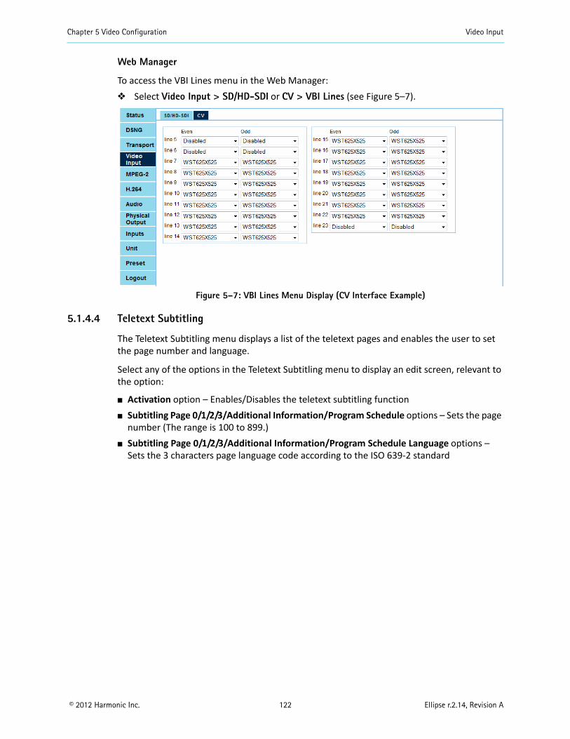
Chapter 5 Video Configuration Video Input
© 2012 Harmonic Inc. 122 Ellipse r.2.14, Revision A
Web Manager
To access the VBI Lines menu in the Web Manager: Select Video Input > SD/HD-SDI or CV > VBI Lines (see Figure 5–7).
Figure 5–7: VBI Lines Menu Display (CV Interface Example)
5.1.4.4 Teletext Subtitling
The Teletext Subtitling menu displays a list of the teletext pages and enables the user to set the page number and language.
Select any of the options in the Teletext Subtitling menu to display an edit screen, relevant to the option:
Activation option – Enables/Disables the teletext subtitling function Subtitling Page 0/1/2/3/Additional Information/Program Schedule options – Sets the page
number (The range is 100 to 899.) Subtitling Page 0/1/2/3/Additional Information/Program Schedule Language options –
Sets the 3 characters page language code according to the ISO 639-2 standard
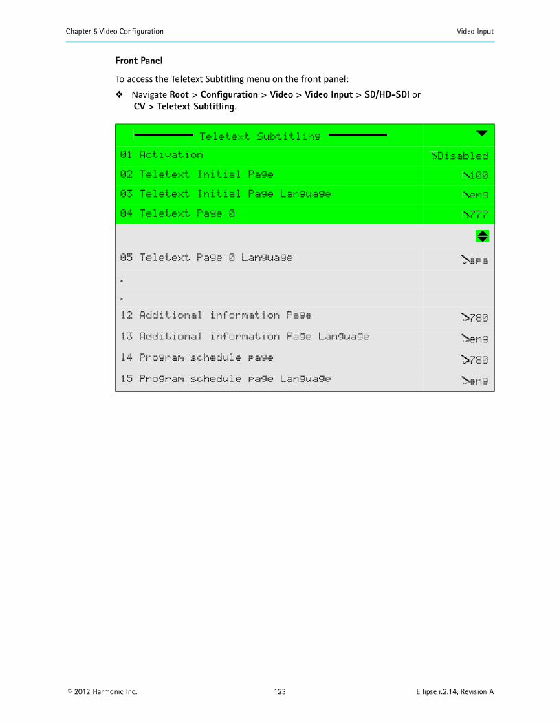
Chapter 5 Video Configuration Video Input
© 2012 Harmonic Inc. 123 Ellipse r.2.14, Revision A
Front Panel
To access the Teletext Subtitling menu on the front panel: Navigate Root > Configuration > Video > Video Input > SD/HD-SDI or
CV > Teletext Subtitling.
Teletext Subtitling
01 Activation Disabled
02 Teletext Initial Page 100
03 Teletext Initial Page Language eng
04 Teletext Page 0 777
05 Teletext Page 0 Language spa
.
.
12 Additional information Page 780
13 Additional information Page Language eng
14 Program schedule page 780
15 Program schedule page Language eng
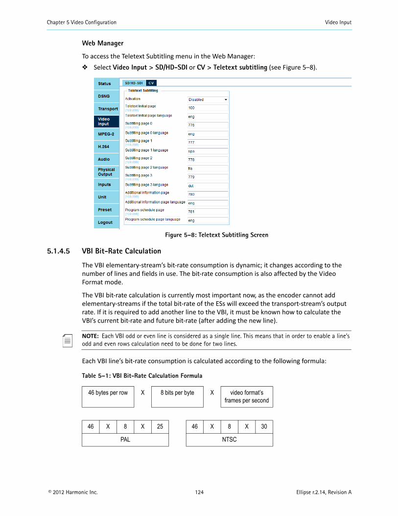
Chapter 5 Video Configuration Video Input
© 2012 Harmonic Inc. 124 Ellipse r.2.14, Revision A
Web Manager
To access the Teletext Subtitling menu in the Web Manager: Select Video Input > SD/HD-SDI or CV > Teletext subtitling (see Figure 5–8).
Figure 5–8: Teletext Subtitling Screen
5.1.4.5 VBI Bit-Rate Calculation
The VBI elementary-stream’s bit-rate consumption is dynamic; it changes according to the number of lines and fields in use. The bit-rate consumption is also affected by the Video Format mode.
The VBI bit-rate calculation is currently most important now, as the encoder cannot add elementary-streams if the total bit-rate of the ESs will exceed the transport-stream’s output rate. If it is required to add another line to the VBI, it must be known how to calculate the VBI’s current bit-rate and future bit-rate (after adding the new line).
NOTE: Each VBI odd or even line is considered as a single line. This means that in order to enable a line’s odd and even rows calculation need to be done for two lines.
Each VBI line’s bit-rate consumption is calculated according to the following formula:
Table 5–1: VBI Bit-Rate Calculation Formula
46 bytes per row X 8 bits per byte X video format’s frames per second
46 X 8 X 25 46 X 8 X 30
PAL NTSC
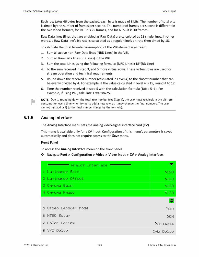
Chapter 5 Video Configuration Video Input
© 2012 Harmonic Inc. 125 Ellipse r.2.14, Revision A
Each row takes 46 bytes from the packet, each byte is made of 8 bits; The number of total bits is timed by the number of frames per second. The number of frames per second is different in the two video formats, for PAL it is 25 frames, and for NTSC it is 30 frames.
Raw Data lines (lines that are enabled as Raw Data) are calculated as 18 single lines. In other words, a Raw Data line’s bit-rate is calculated as a regular line’s bit-rate then timed by 18.
To calculate the total bit-rate consumption of the VBI elementary-stream:1. Sum all active non-Raw-Data lines (NRD Lines) in the VBI.2. Sum all Raw-Data lines (RD Lines) in the VBI.3. Sum the total Lines using the following formula: (NRD Lines)+18*(RD Line)4. To the sum received in step 3, add 5 more virtual rows. These virtual rows are used for
stream operation and technical requirements.5. Round down the received number (calculated in Level 4) to the closest number that can
be evenly divided by 4. For example, if the value calculated in level 4 is 15, round it to 12.6. Time the number received in step 5 with the calculation formula (Table 5–1). For
example, if using PAL, calculate 12x46x8x25.
NOTE: Due to rounding down the total row number (see Step 4), the user must recalculate the bit-rate consumption every time when trying to add a new row, as it may change the final numbers. The user cannot just add (+1) to the final number (timed by the formula).
5.1.5 Analog Interface
The Analog Interface menu sets the analog video-signal interface card (CV).
This menu is available only for a CV input. Configuration of this menu’s parameters is saved automatically and does not require access to the Save menu.
Front Panel
To access the Analog Interface menu on the front panel: Navigate Root > Configuration > Video > Video Input > CV > Analog Interface.
Analog Interface
1 Luminance Gain 128
2 Luminance Offset 128
3 Chroma Gain 128
4 Chroma Phase 128
5 Video Decoder Mode TV
6 NTSC Setup ON
7 Color Coring Disable
8 Y/C Delay No Delay
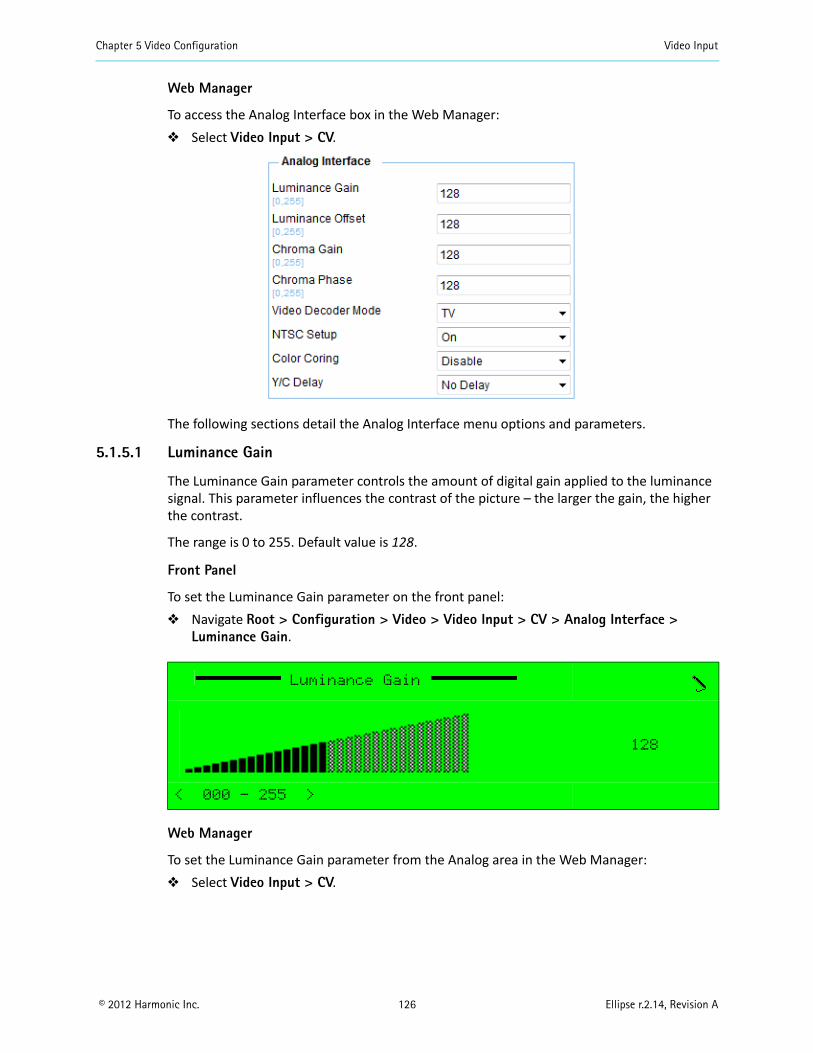
Chapter 5 Video Configuration Video Input
© 2012 Harmonic Inc. 126 Ellipse r.2.14, Revision A
Web Manager
To access the Analog Interface box in the Web Manager: Select Video Input > CV.
The following sections detail the Analog Interface menu options and parameters.
5.1.5.1 Luminance Gain
The Luminance Gain parameter controls the amount of digital gain applied to the luminance signal. This parameter influences the contrast of the picture – the larger the gain, the higher the contrast.
The range is 0 to 255. Default value is 128.
Front Panel
To set the Luminance Gain parameter on the front panel: Navigate Root > Configuration > Video > Video Input > CV > Analog Interface >
Luminance Gain.
Web Manager
To set the Luminance Gain parameter from the Analog area in the Web Manager: Select Video Input > CV.
Luminance Gain
128
< 000 - 255 >
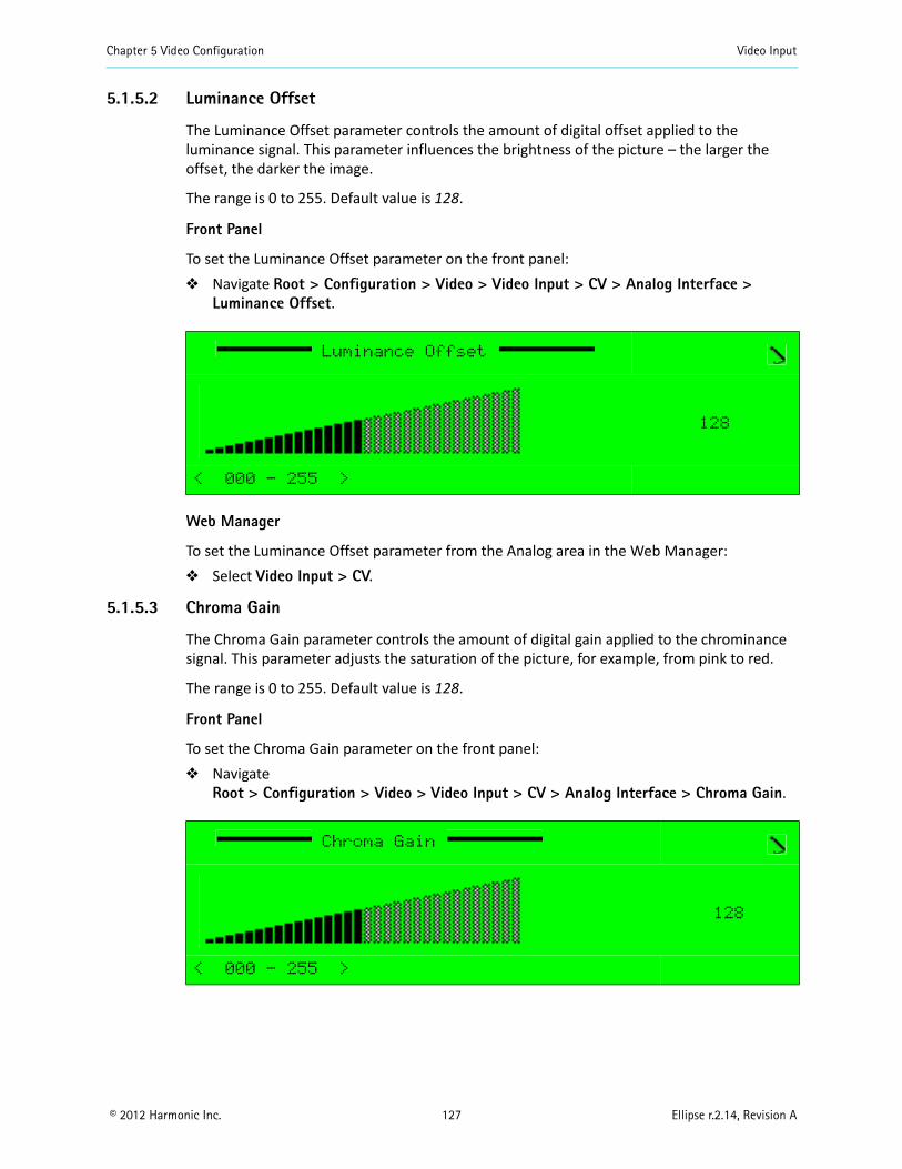
Chapter 5 Video Configuration Video Input
© 2012 Harmonic Inc. 127 Ellipse r.2.14, Revision A
5.1.5.2 Luminance Offset
The Luminance Offset parameter controls the amount of digital offset applied to the luminance signal. This parameter influences the brightness of the picture – the larger the offset, the darker the image.
The range is 0 to 255. Default value is 128.
Front Panel
To set the Luminance Offset parameter on the front panel: Navigate Root > Configuration > Video > Video Input > CV > Analog Interface >
Luminance Offset.
Web Manager
To set the Luminance Offset parameter from the Analog area in the Web Manager: Select Video Input > CV.
5.1.5.3 Chroma Gain
The Chroma Gain parameter controls the amount of digital gain applied to the chrominance signal. This parameter adjusts the saturation of the picture, for example, from pink to red.
The range is 0 to 255. Default value is 128.
Front Panel
To set the Chroma Gain parameter on the front panel: Navigate
Root > Configuration > Video > Video Input > CV > Analog Interface > Chroma Gain.
Luminance Offset
128
< 000 - 255 >
Chroma Gain
128
< 000 - 255 >
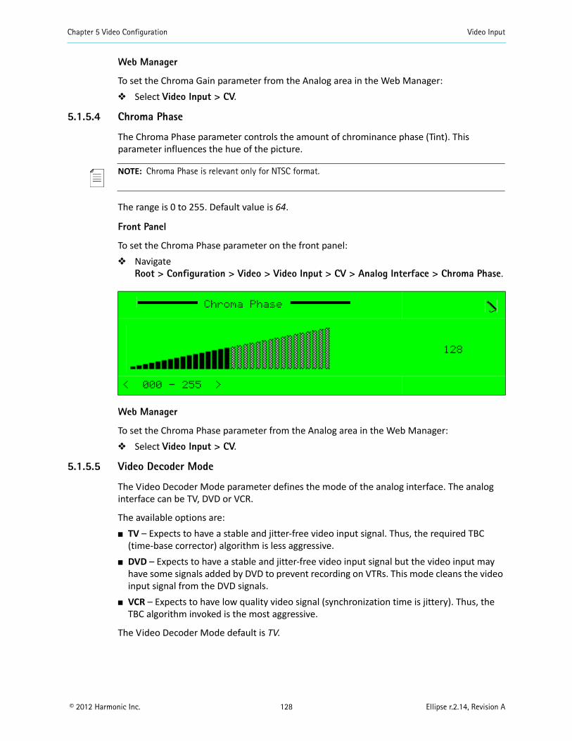
Chapter 5 Video Configuration Video Input
© 2012 Harmonic Inc. 128 Ellipse r.2.14, Revision A
Web Manager
To set the Chroma Gain parameter from the Analog area in the Web Manager: Select Video Input > CV.
5.1.5.4 Chroma Phase
The Chroma Phase parameter controls the amount of chrominance phase (Tint). This parameter influences the hue of the picture.
NOTE: Chroma Phase is relevant only for NTSC format.
The range is 0 to 255. Default value is 64.
Front Panel
To set the Chroma Phase parameter on the front panel: Navigate
Root > Configuration > Video > Video Input > CV > Analog Interface > Chroma Phase.
Web Manager
To set the Chroma Phase parameter from the Analog area in the Web Manager: Select Video Input > CV.
5.1.5.5 Video Decoder Mode
The Video Decoder Mode parameter defines the mode of the analog interface. The analog interface can be TV, DVD or VCR.
The available options are: TV – Expects to have a stable and jitter-free video input signal. Thus, the required TBC
(time-base corrector) algorithm is less aggressive. DVD – Expects to have a stable and jitter-free video input signal but the video input may
have some signals added by DVD to prevent recording on VTRs. This mode cleans the video input signal from the DVD signals.
VCR – Expects to have low quality video signal (synchronization time is jittery). Thus, the TBC algorithm invoked is the most aggressive.
The Video Decoder Mode default is TV.
Chroma Phase
128
< 000 - 255 >

Chapter 5 Video Configuration Video Input
© 2012 Harmonic Inc. 129 Ellipse r.2.14, Revision A
Front Panel
To set the Video Decoder Mode parameter on the front panel: Navigate
Root > Configuration > Video > Video Input > CV > Analog Interface > Video Decoder Mode (see the following example):
Web Manager
To set the Video Decoder Mode parameter from the Analog area in the Web Manager: Select Video Input > CV.
5.1.5.6 NTSC Setup
The NTSC Setup parameter enables the NTSC setup level option. It refers to the black level of the analog video signal.
NOTE: Setup level is relevant only for NTSC format.
The available options are:
On – Black level is higher than Blank level. Off – Black level is equal to Blank level.
The NTSC Setup default value is On.
Front Panel
To set the NTSC Setup parameter on the front panel: Navigate
Root > Configuration > Video > Video Input > CV > Analog Interface > NTSC Setup.
Video Decoder Mode
1 ƒ TV
2 ‚ DVD
3 ‚ VCR
NTSC Setup
1 ƒ On
2 ‚ Off
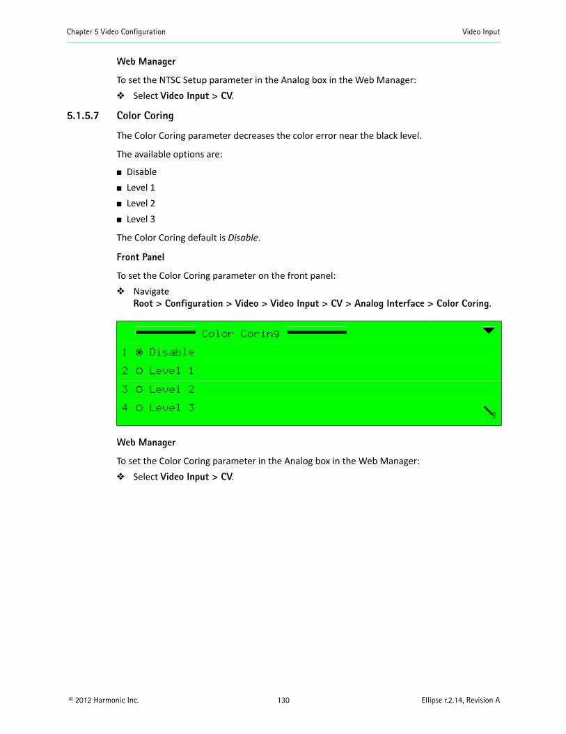
Chapter 5 Video Configuration Video Input
© 2012 Harmonic Inc. 130 Ellipse r.2.14, Revision A
Web Manager
To set the NTSC Setup parameter in the Analog box in the Web Manager: Select Video Input > CV.
5.1.5.7 Color Coring
The Color Coring parameter decreases the color error near the black level.
The available options are:
Disable Level 1 Level 2 Level 3
The Color Coring default is Disable.
Front Panel
To set the Color Coring parameter on the front panel: Navigate
Root > Configuration > Video > Video Input > CV > Analog Interface > Color Coring.
Web Manager
To set the Color Coring parameter in the Analog box in the Web Manager: Select Video Input > CV.
Color Coring
1 ƒ Disable
2 ‚ Level 1
3 ‚ Level 2
4 ‚ Level 3
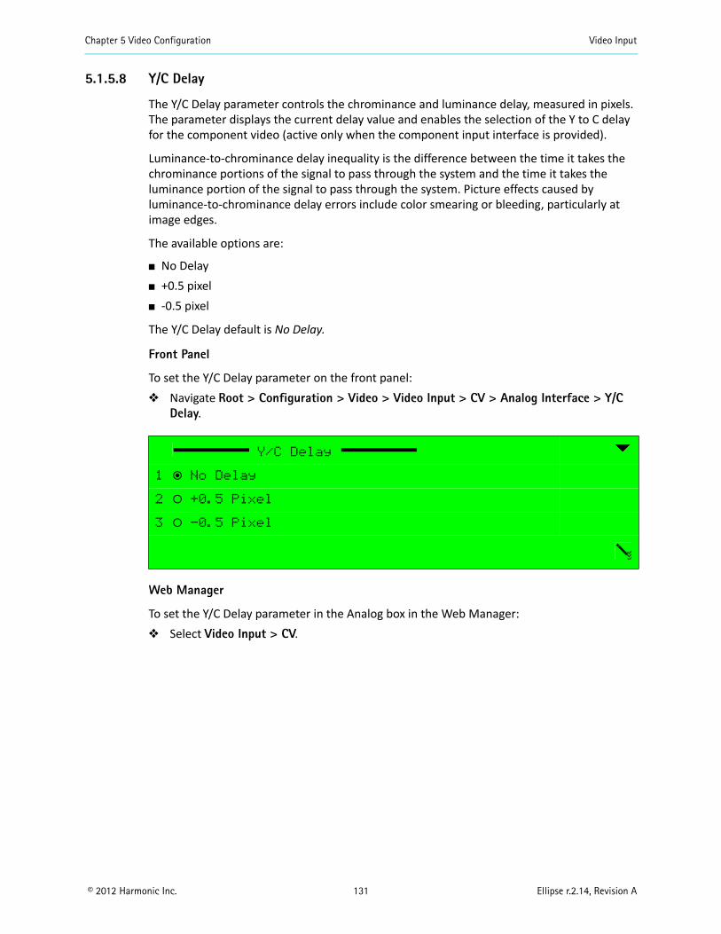
Chapter 5 Video Configuration Video Input
© 2012 Harmonic Inc. 131 Ellipse r.2.14, Revision A
5.1.5.8 Y/C Delay
The Y/C Delay parameter controls the chrominance and luminance delay, measured in pixels. The parameter displays the current delay value and enables the selection of the Y to C delay for the component video (active only when the component input interface is provided).
Luminance-to-chrominance delay inequality is the difference between the time it takes the chrominance portions of the signal to pass through the system and the time it takes the luminance portion of the signal to pass through the system. Picture effects caused by luminance-to-chrominance delay errors include color smearing or bleeding, particularly at image edges.
The available options are:
No Delay +0.5 pixel -0.5 pixel
The Y/C Delay default is No Delay.
Front Panel
To set the Y/C Delay parameter on the front panel: Navigate Root > Configuration > Video > Video Input > CV > Analog Interface > Y/C
Delay.
Web Manager
To set the Y/C Delay parameter in the Analog box in the Web Manager: Select Video Input > CV.
Y/C Delay
1 ƒ No Delay
2 ‚ +0.5 Pixel
3 ‚ -0.5 Pixel
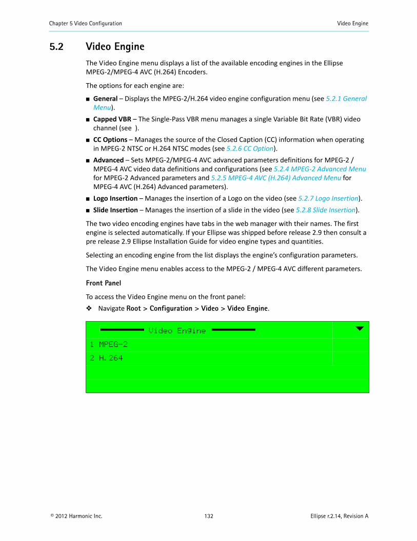
Chapter 5 Video Configuration Video Engine
© 2012 Harmonic Inc. 132 Ellipse r.2.14, Revision A
5.2 Video EngineThe Video Engine menu displays a list of the available encoding engines in the Ellipse MPEG-2/MPEG-4 AVC (H.264) Encoders.
The options for each engine are:
General – Displays the MPEG-2/H.264 video engine configuration menu (see 5.2.1 General Menu).
Capped VBR – The Single-Pass VBR menu manages a single Variable Bit Rate (VBR) video channel (see ).
CC Options – Manages the source of the Closed Caption (CC) information when operating in MPEG-2 NTSC or H.264 NTSC modes (see 5.2.6 CC Option).
Advanced – Sets MPEG-2/MPEG-4 AVC advanced parameters definitions for MPEG-2 / MPEG-4 AVC video data definitions and configurations (see 5.2.4 MPEG-2 Advanced Menu for MPEG-2 Advanced parameters and 5.2.5 MPEG-4 AVC (H.264) Advanced Menu for MPEG-4 AVC (H.264) Advanced parameters).
Logo Insertion – Manages the insertion of a Logo on the video (see 5.2.7 Logo Insertion). Slide Insertion – Manages the insertion of a slide in the video (see 5.2.8 Slide Insertion).
The two video encoding engines have tabs in the web manager with their names. The first engine is selected automatically. If your Ellipse was shipped before release 2.9 then consult a pre release 2.9 Ellipse Installation Guide for video engine types and quantities.
Selecting an encoding engine from the list displays the engine’s configuration parameters.
The Video Engine menu enables access to the MPEG-2 / MPEG-4 AVC different parameters.
Front Panel
To access the Video Engine menu on the front panel: Navigate Root > Configuration > Video > Video Engine.
Video Engine
1 MPEG-2
2 H.264
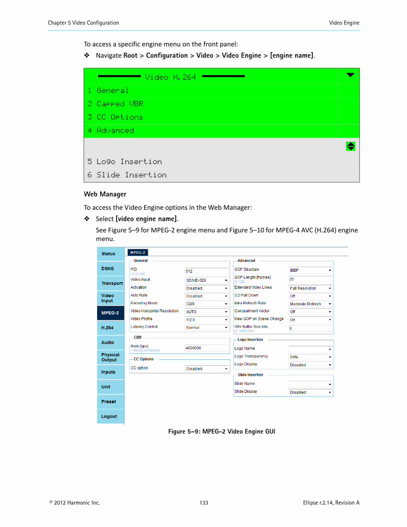
Chapter 5 Video Configuration Video Engine
© 2012 Harmonic Inc. 133 Ellipse r.2.14, Revision A
To access a specific engine menu on the front panel: Navigate Root > Configuration > Video > Video Engine > [engine name].
Web Manager
To access the Video Engine options in the Web Manager: Select [video engine name].
See Figure 5–9 for MPEG-2 engine menu and Figure 5–10 for MPEG-4 AVC (H.264) engine menu.
Figure 5–9: MPEG-2 Video Engine GUI
Video H.264
1 General
2 Capped VBR
3 CC Options
4 Advanced
5 Logo Insertion
6 Slide Insertion
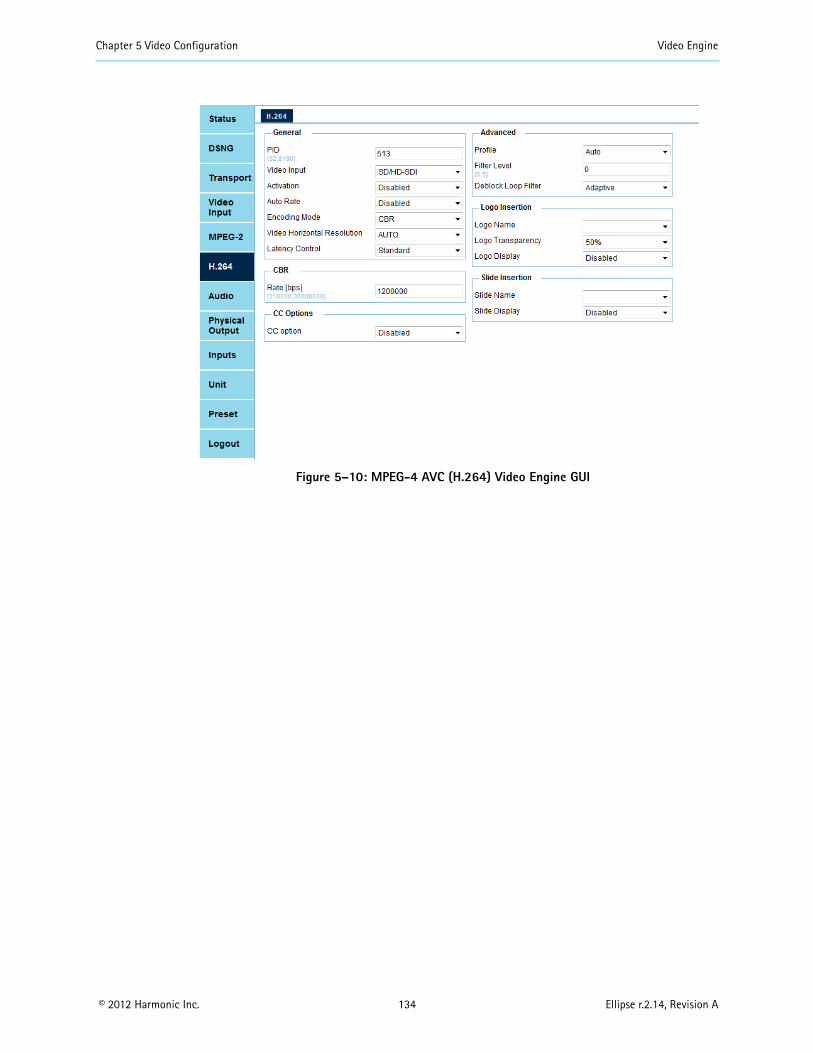
Chapter 5 Video Configuration Video Engine
© 2012 Harmonic Inc. 134 Ellipse r.2.14, Revision A
Figure 5–10: MPEG-4 AVC (H.264) Video Engine GUI
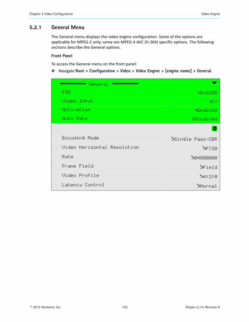
Chapter 5 Video Configuration Video Engine
© 2012 Harmonic Inc. 135 Ellipse r.2.14, Revision A
5.2.1 General Menu
The General menu displays the video engine configuration. Some of the options are applicable for MPEG-2 only; some are MPEG-4 AVC (H.264) specific options. The following sections describe the General options.
Front Panel
To access the General menu on the front panel: Navigate Root > Configuration > Video > Video Engine > [engine name] > General.
General
PID 0x0200
Video Input CV
Activation Enabled
Auto Rate Disabled
Encoding Mode Single Pass-CBR
Video Horizontal Resolution F720
Rate 04000000
Frame Field Field
Video Profile 4:2:0
Latency Control Normal
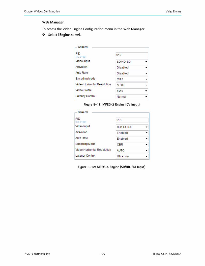
Chapter 5 Video Configuration Video Engine
© 2012 Harmonic Inc. 136 Ellipse r.2.14, Revision A
Web Manager
To access the Video Engine Configuration menu in the Web Manager: Select [Engine name].
Figure 5–11: MPEG-2 Engine (CV Input)
Figure 5–12: MPEG-4 Engine (SD/HD-SDI Input)
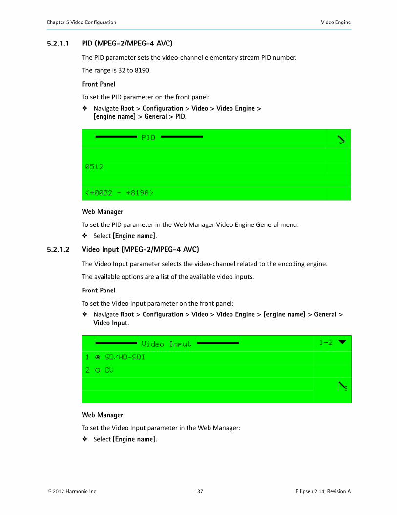
Chapter 5 Video Configuration Video Engine
© 2012 Harmonic Inc. 137 Ellipse r.2.14, Revision A
5.2.1.1 PID (MPEG-2/MPEG-4 AVC)
The PID parameter sets the video-channel elementary stream PID number.
The range is 32 to 8190.
Front Panel
To set the PID parameter on the front panel: Navigate Root > Configuration > Video > Video Engine >
[engine name] > General > PID.
Web Manager
To set the PID parameter in the Web Manager Video Engine General menu: Select [Engine name].
5.2.1.2 Video Input (MPEG-2/MPEG-4 AVC)
The Video Input parameter selects the video-channel related to the encoding engine.
The available options are a list of the available video inputs.
Front Panel
To set the Video Input parameter on the front panel: Navigate Root > Configuration > Video > Video Engine > [engine name] > General >
Video Input.
Web Manager
To set the Video Input parameter in the Web Manager: Select [Engine name].
PID
0512
<+0032 - +8190>
Video Input 1-2
1 ƒ SD/HD-SDI
2 ‚ CV

Chapter 5 Video Configuration Video Engine
© 2012 Harmonic Inc. 138 Ellipse r.2.14, Revision A
5.2.1.3 Activation (MPEG-2/MPEG-4 AVC)
The Activation parameter sets the video-channel activation mode.
The available options are: Enabled – Video channel is enabled and active. Disabled – Video channel is disabled.
The Activation default is Disabled.
Front Panel
To set the Activation parameter on the front panel: Navigate
Root > Configuration > Video > Video Engine > [engine name] > General > Activation.
Web Manager
To set the Activation parameter in the Web Manager Video Engine General menu: Select [Engine name].
5.2.1.4 Auto Rate
Use the Auto Rate parameter to use the maximum possible video rate. If there is no DSNG the video is connected to an enabled IP out and the IP out rate is used. If there is no IP out enabled it uses ASI and the ASI rate is used.
The options are:
Enabled Disabled
5.2.1.5 Encoding Mode (MPEG-2/MPEG-4 AVC)
The Encoding Mode parameter sets the video single pass encoding mode using CBR (constant bit-rate) or VBR (variable bit-rate).
The available options are:
CBR – Sets the encoding mode to a single pass constant bit-rate mode. Capped – VBR – Sets the encoding mode to a variable bit-rate mode. This mode enables
the VBR menu, in which the user must set the maximum bit-rate of the video stream and its minimal quality level (see 5.2.3 Capped-VBR Menu).
Activation
1 ƒ Disabled
2 ‚ Enabled
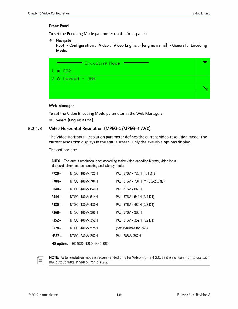
Chapter 5 Video Configuration Video Engine
© 2012 Harmonic Inc. 139 Ellipse r.2.14, Revision A
Front Panel
To set the Encoding Mode parameter on the front panel: Navigate
Root > Configuration > Video > Video Engine > [engine name] > General > Encoding Mode.
Web Manager
To set the Video Encoding Mode parameter in the Web Manager: Select [Engine name].
5.2.1.6 Video Horizontal Resolution (MPEG-2/MPEG-4 AVC)
The Video Horizontal Resolution parameter defines the current video-resolution mode. The current resolution displays in the status screen. Only the available options display.
The options are:
NOTE: Auto resolution mode is recommended only for Video Profile 4:2:0, as it is not common to use such low output rates in Video Profile 4:2:2.
Encoding Mode
1 ƒ CBR
2 ‚ Capped - VBR
AUTO – The output resolution is set according to the video encoding bit rate, video input standard, chrominance sampling and latency mode.
F720 – NTSC: 480Vx 720H PAL: 576V x 720H (Full D1)
F704 – NTSC: 480Vx 704H PAL: 576V x 704H (MPEG-2 Only)
F640 – NTSC: 480Vx 640H PAL: 576V x 640H
F544 – NTSC: 480Vx 544H PAL: 576V x 544H (3/4 D1)
F480 – NTSC: 480Vx 480H PAL: 576V x 480H (2/3 D1)
F368– NTSC: 480Vx 386H PAL: 576V x 386H
F352 – NTSC: 480Vx 352H PAL: 576V x 352H (1/2 D1)
F528 – NTSC: 480Vx 528H (Not available for PAL)
H352 – NTSC: 240Vx 352H PAL: 288Vx 352H
HD options – HD1920, 1280, 1440, 960
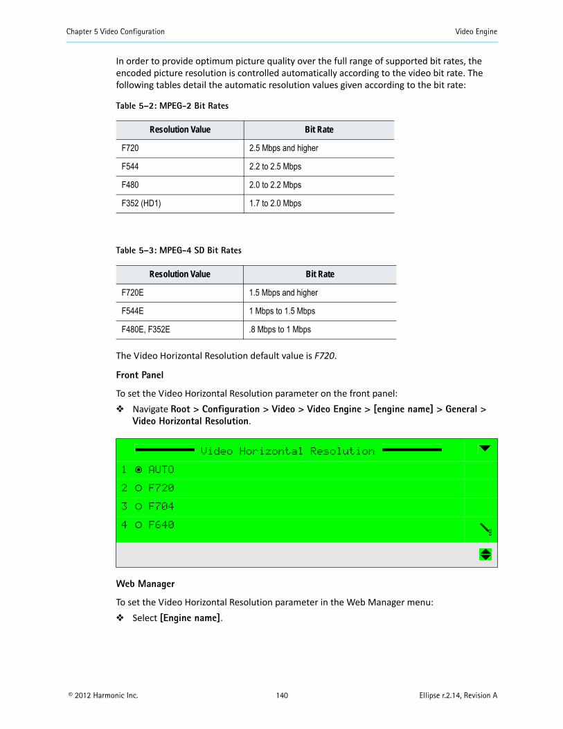
Chapter 5 Video Configuration Video Engine
© 2012 Harmonic Inc. 140 Ellipse r.2.14, Revision A
In order to provide optimum picture quality over the full range of supported bit rates, the encoded picture resolution is controlled automatically according to the video bit rate. The following tables detail the automatic resolution values given according to the bit rate:
The Video Horizontal Resolution default value is F720.
Front Panel
To set the Video Horizontal Resolution parameter on the front panel: Navigate Root > Configuration > Video > Video Engine > [engine name] > General >
Video Horizontal Resolution.
Web Manager
To set the Video Horizontal Resolution parameter in the Web Manager menu: Select [Engine name].
Table 5–2: MPEG-2 Bit Rates
Resolution Value Bit Rate
F720 2.5 Mbps and higher
F544 2.2 to 2.5 Mbps
F480 2.0 to 2.2 Mbps
F352 (HD1) 1.7 to 2.0 Mbps
Table 5–3: MPEG-4 SD Bit Rates
Resolution Value Bit Rate
F720E 1.5 Mbps and higher
F544E 1 Mbps to 1.5 Mbps
F480E, F352E .8 Mbps to 1 Mbps
Video Horizontal Resolution
1 ƒ AUTO
2 ‚ F720
3 ‚ F704
4 ‚ F640
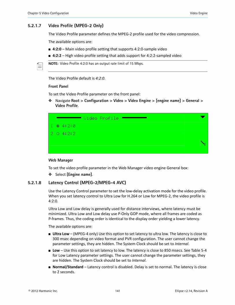
Chapter 5 Video Configuration Video Engine
© 2012 Harmonic Inc. 141 Ellipse r.2.14, Revision A
5.2.1.7 Video Profile (MPEG-2 Only)
The Video Profile parameter defines the MPEG-2 profile used for the video compression.
The available options are:
4:2:0 – Main video profile setting that supports 4:2:0-sample video 4:2:2 – High video profile setting that adds support for 4:2:2-sampled video
NOTE: Video Profile 4:2:0 has an output rate limit of 15 Mbps.
The Video Profile default is 4:2:0.
Front Panel
To set the Video Profile parameter on the front panel: Navigate Root > Configuration > Video > Video Engine > [engine name] > General >
Video Profile.
Web Manager
To set the video profile parameter in the Web Manager video engine General box: Select [Engine name].
5.2.1.8 Latency Control (MPEG-2/MPEG-4 AVC)
Use the Latency Control parameter to set the low-delay activation mode for the video profile. When you set latency control to Ultra Low for H.264 or Low for MPEG-2, the video profile is 4:2:0.
Ultra Low and Low delay is generally used for distance interviews, where latency must be minimized. Ultra Low and Low delay use P-Only GOP mode, where all frames are coded as P-frames. Thus, the coding order is identical to the display order yielding a lower latency.
The available options are:
Ultra Low – (MPEG-4 only) Use this option to set latency to ultra low. The latency is close to 300 msec depending on video format and PVR configuration. The user cannot change the parameter settings, they are hidden. The System Clock should be set to Internal.
Low – Use this option to set latency to low. The latency is close to 850 msecs. See Table 5-4 for Low Latency parameter settings. The user cannot change the parameter settings, they are hidden. The System Clock should be set to Internal.
Normal/Standard – Latency control is disabled. Delay is set to normal. The latency is close to 2 seconds.
Video Profile
1 ƒ 4:2:0
2 ‚ 4:2:2
Chapter 5 Video Configuration Video Engine
© 2012 Harmonic Inc. 142 Ellipse r.2.14, Revision A
Manual – (MPEG-4 only) This mode can have a negative effect on the video quality and is not recommended. Manual mode enables the user to set the following parameters: GOP Structure GOP Length IDR Interval New GOP on Scene Change VBV Buffer Size bits
NOTE: When setting the Latency control to Ultra Low Delay, the audio bit-rate must be set to a high rate. If the audio bit-rate is not high enough, the encoder displays the dependency check message, avsync mismatch. audio# and video#.
The Latency Control default is Normal/Standard.
Table 5-4: Low Latency Parameter Settings
Parameter Setting
FPGA Scene Cut Detection Disabled
GOP structure IBP
GOP length 64
VBV delay 0.5 sec
IDR interval 0
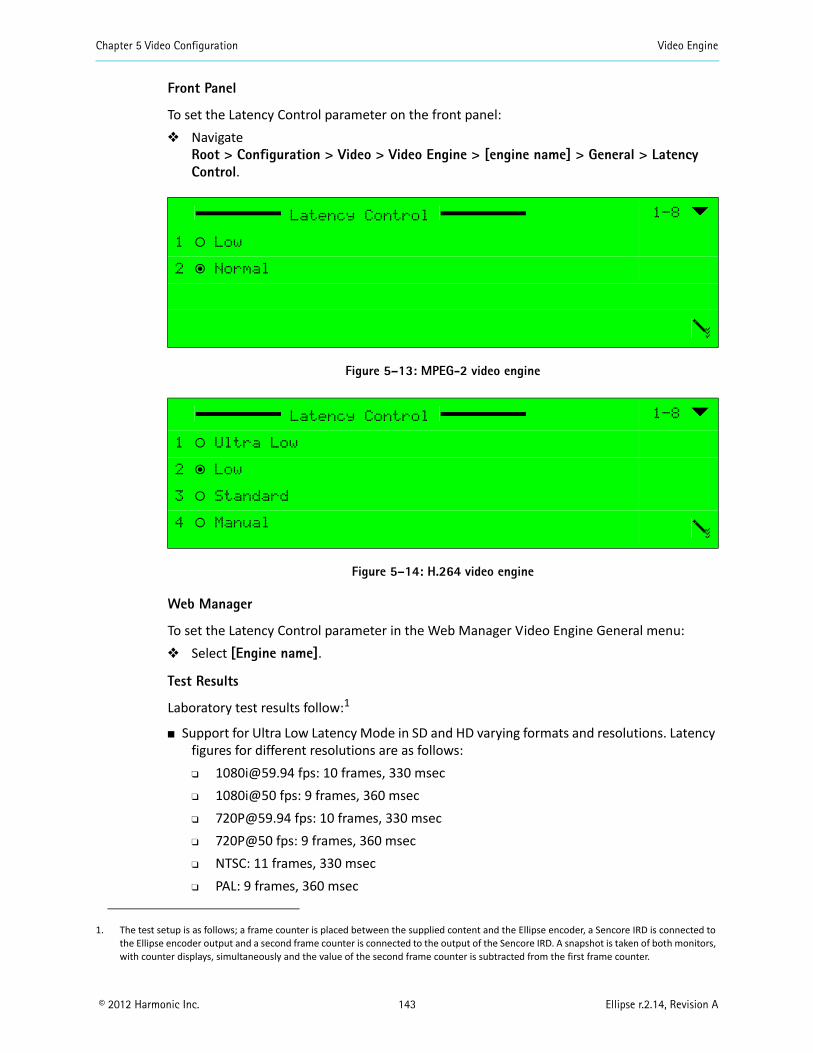
Chapter 5 Video Configuration Video Engine
© 2012 Harmonic Inc. 143 Ellipse r.2.14, Revision A
Front Panel
To set the Latency Control parameter on the front panel: Navigate
Root > Configuration > Video > Video Engine > [engine name] > General > Latency Control.
Figure 5–13: MPEG-2 video engine
Figure 5–14: H.264 video engine
Web Manager
To set the Latency Control parameter in the Web Manager Video Engine General menu: Select [Engine name].
Test Results
Laboratory test results follow:1
Support for Ultra Low Latency Mode in SD and HD varying formats and resolutions. Latency figures for different resolutions are as follows: [email protected] fps: 10 frames, 330 msec 1080i@50 fps: 9 frames, 360 msec [email protected] fps: 10 frames, 330 msec 720P@50 fps: 9 frames, 360 msec NTSC: 11 frames, 330 msec PAL: 9 frames, 360 msec
Latency Control 1-8
1 ‚ Low
2 ƒ Normal
Latency Control 1-8
1 ‚ Ultra Low
2 ƒ Low
3 ‚ Standard
4 ‚ Manual
1. The test setup is as follows; a frame counter is placed between the supplied content and the Ellipse encoder, a Sencore IRD is connected to the Ellipse encoder output and a second frame counter is connected to the output of the Sencore IRD. A snapshot is taken of both monitors, with counter displays, simultaneously and the value of the second frame counter is subtracted from the first frame counter.

Chapter 5 Video Configuration Video Engine
© 2012 Harmonic Inc. 144 Ellipse r.2.14, Revision A
Using the DSNG application: For DVB-S2 with frame length of 64,800, add the following latency figures to the
latency figures in the bulleted list above with different resolutions.• 15 Msymbol: 0 msec• 10 Msymbol: 0 msec• 7 Msymbol: 40 msec• 4 Msymbol: 80 msec• 2 Msymbol: 120 msec• 1 Msymbol: 160 msec
For DVB-S add the following latency figures to the latency figures in the bulleted list above with different resolutions.
• 15 Msymbol: 0 msec• 10 Msymbol: 0 msec• 7 Msymbol: 40 msec• 4 Msymbol: 80 msec• 2 Msymbol: 120 msec• 1 Msymbol: 160 msec
Using MPEG over IP front end; add the following latency figures to the latency figures in the bulleted list above with different resolutions. MPEG over IP without FEC and IRD de jitter set to 0 msec: 0 msec MPEG over IP with FEC and IRD de jitter set to 0 msec: 0–1 frame MPEG over IP without FEC and with IRD de jitter set to 200 msec: 200 msec
NOTE: Low latency MPEG-4 AVC laboratory tests with the Ellipse encoder and the Tandberg decoder, connected via DVB-ASI, showed an end to end latency of 500 msec in all formats. In order to achieve optimal video quality when working with the Tandberg decoder one needs to configure the VBV buffer to a value equal to the result of the following equation: video bit rate x 0.3. Setting VBV to a value lower than the aforementioned, results in VQ degradation.
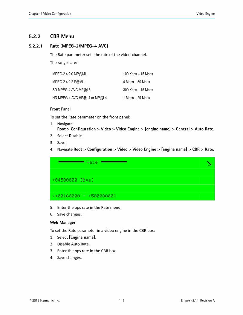
Chapter 5 Video Configuration Video Engine
© 2012 Harmonic Inc. 145 Ellipse r.2.14, Revision A
5.2.2 CBR Menu
5.2.2.1 Rate (MPEG-2/MPEG-4 AVC)
The Rate parameter sets the rate of the video-channel.
The ranges are:
Front Panel
To set the Rate parameter on the front panel:1. Navigate
Root > Configuration > Video > Video Engine > [engine name] > General > Auto Rate.2. Select Disable.3. Save.4. Navigate Root > Configuration > Video > Video Engine > [engine name] > CBR > Rate.
5. Enter the bps rate in the Rate menu.6. Save changes.
Web Manager
To set the Rate parameter in a video engine in the CBR box:1. Select [Engine name].2. Disable Auto Rate.3. Enter the bps rate in the CBR box.4. Save changes.
MPEG-2 4:2:0 MP@ML 100 Kbps – 15 Mbps
MPEG-2 4:2:2 P@ML 4 Mbps – 50 Mbps
SD MPEG-4 AVC MP@L3 300 Kbps – 15 Mbps
HD MPEG-4 AVC HP@L4 or MP@L4 1 Mbps – 29 Mbps
Rate
+04500000 [bps]
<+00160000 - +50000000>
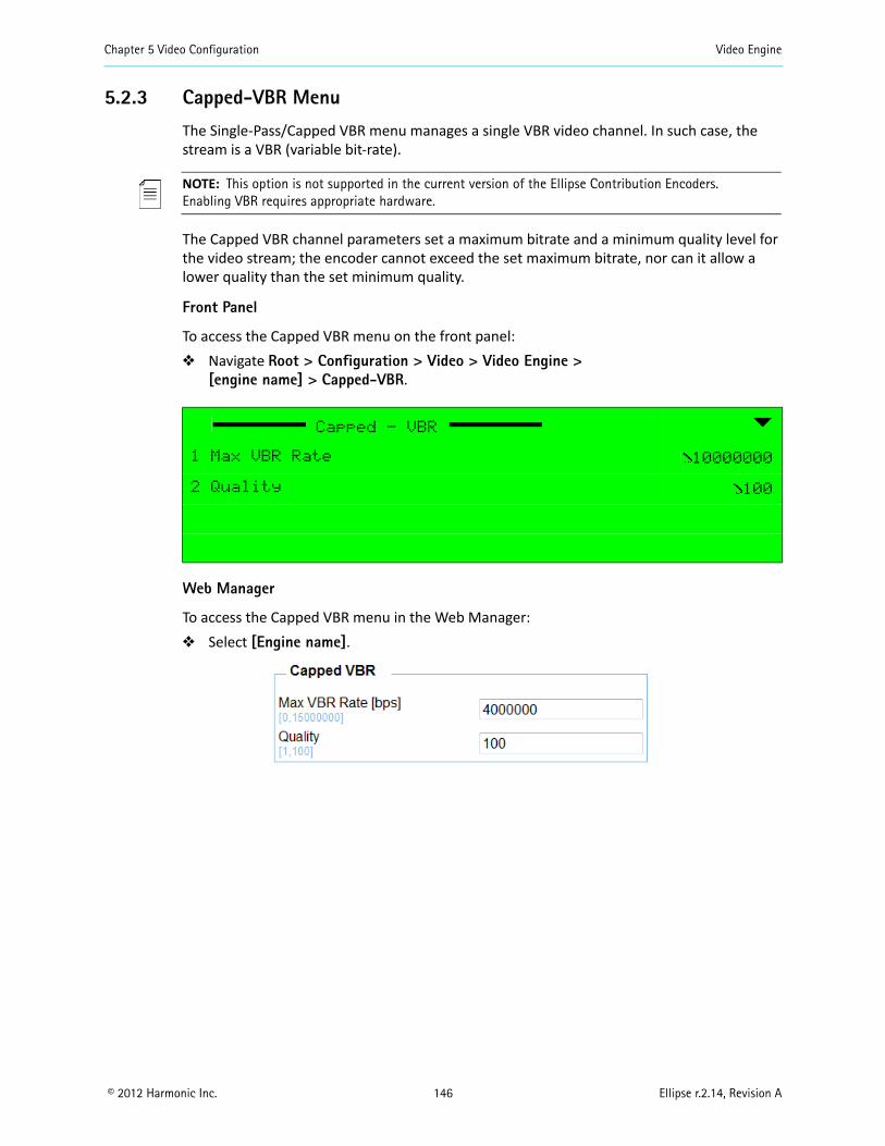
Chapter 5 Video Configuration Video Engine
© 2012 Harmonic Inc. 146 Ellipse r.2.14, Revision A
5.2.3 Capped-VBR Menu
The Single-Pass/Capped VBR menu manages a single VBR video channel. In such case, the stream is a VBR (variable bit-rate).
NOTE: This option is not supported in the current version of the Ellipse Contribution Encoders.Enabling VBR requires appropriate hardware.
The Capped VBR channel parameters set a maximum bitrate and a minimum quality level for the video stream; the encoder cannot exceed the set maximum bitrate, nor can it allow a lower quality than the set minimum quality.
Front Panel
To access the Capped VBR menu on the front panel: Navigate Root > Configuration > Video > Video Engine >
[engine name] > Capped-VBR.
Web Manager
To access the Capped VBR menu in the Web Manager: Select [Engine name].
Capped - VBR
1 Max VBR Rate 10000000
2 Quality 100
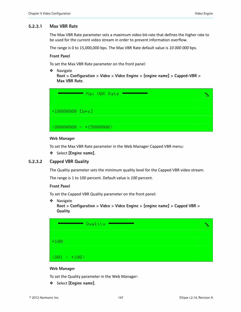
Chapter 5 Video Configuration Video Engine
© 2012 Harmonic Inc. 147 Ellipse r.2.14, Revision A
5.2.3.1 Max VBR Rate
The Max VBR Rate parameter sets a maximum video bit-rate that defines the higher rate to be used for the current video stream in order to prevent information overflow.
The range is 0 to 15,000,000 bps. The Max VBR Rate default value is 10 000 000 bps.
Front Panel
To set the Max VBR Rate parameter on the front panel: Navigate
Root > Configuration > Video > Video Engine > [engine name] > Capped-VBR >Max VBR Rate.
Web Manager
To set the Max VBR Rate parameter in the Web Manager Capped VBR menu: Select [Engine name].
5.2.3.2 Capped VBR Quality
The Quality parameter sets the minimum quality level for the Capped VBR video stream.
The range is 1 to 100 percent. Default value is 100 percent.
Front Panel
To set the Capped VBR Quality parameter on the front panel: Navigate
Root > Configuration > Video > Video Engine > [engine name] > Capped VBR > Quality.
Web Manager
To set the Quality parameter in the Web Manager: Select [Engine name].
Max VBR Rate
+10000000 [bps]
<00000000 - +15000000>
Quality
+100
<001 - +100>
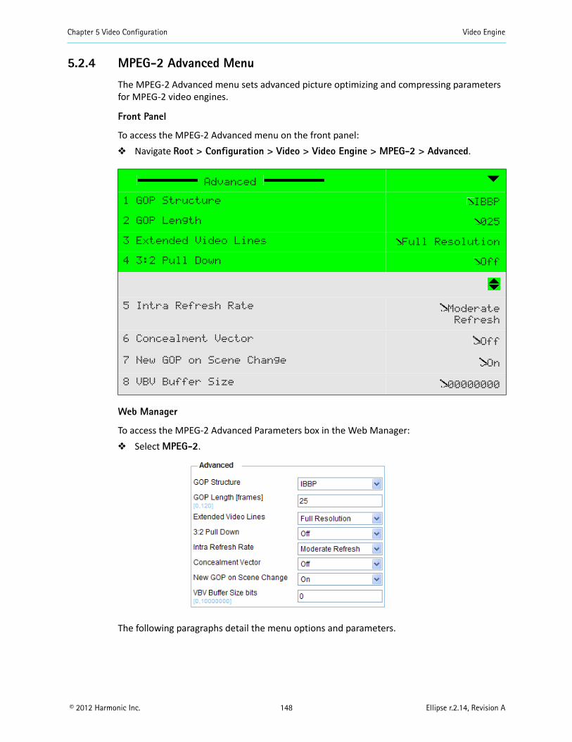
Chapter 5 Video Configuration Video Engine
© 2012 Harmonic Inc. 148 Ellipse r.2.14, Revision A
5.2.4 MPEG-2 Advanced Menu
The MPEG-2 Advanced menu sets advanced picture optimizing and compressing parameters for MPEG-2 video engines.
Front Panel
To access the MPEG-2 Advanced menu on the front panel: Navigate Root > Configuration > Video > Video Engine > MPEG-2 > Advanced.
Web Manager
To access the MPEG-2 Advanced Parameters box in the Web Manager: Select MPEG-2.
The following paragraphs detail the menu options and parameters.
Advanced
1 GOP Structure IBBP
2 GOP Length 025
3 Extended Video Lines Full Resolution
4 3:2 Pull Down Off
5 Intra Refresh Rate Moderate
Refresh
6 Concealment Vector Off
7 New GOP on Scene Change On
8 VBV Buffer Size 00000000
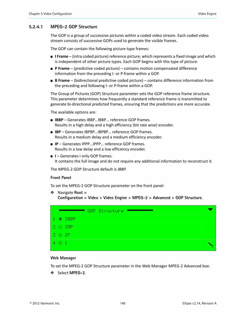
Chapter 5 Video Configuration Video Engine
© 2012 Harmonic Inc. 149 Ellipse r.2.14, Revision A
5.2.4.1 MPEG-2 GOP Structure
The GOP is a group of successive pictures within a coded video stream. Each coded video stream consists of successive GOPs used to generate the visible frames.
The GOP can contain the following picture type frames:
I Frame – (intra coded picture) reference picture, which represents a fixed image and which is independent of other picture types. Each GOP begins with this type of picture.
P Frame – (predictive coded picture) – contains motion compensated difference information from the preceding I- or P-frame within a GOP.
B Frame – (bidirectional predictive coded picture) – contains difference information from the preceding and following I- or P-frame within a GOP.
The Group of Pictures (GOP) Structure parameter sets the GOP reference frame structure. This parameter determines how frequently a standard reference frame is transmitted to generate bi-directional predicted frames, ensuring that the predictions are more accurate.
The available options are:
IBBP – Generates IBBP…IBBP… reference GOP frames. Results in a high delay and a high efficiency (bit rate wise) encoder.
IBP – Generates IBPBP…IBPBP… reference GOP frames. Results in a medium delay and a medium efficiency encoder.
IP – Generates IPPP…IPPP… reference GOP frames. Results in a low delay and a low efficiency encoder.
I – Generates I only GOP frames. It contains the full image and do not require any additional information to reconstruct it.
The MPEG-2 GOP Structure default is IBBP.
Front Panel
To set the MPEG-2 GOP Structure parameter on the front panel: Navigate Root >
Configuration > Video > Video Engine > MPEG-2 > Advanced > GOP Structure.
Web Manager
To set the MPEG-2 GOP Structure parameter in the Web Manager MPEG-2 Advanced box: Select MPEG-2.
GOP Structure
1 ƒ IBBP
2 ‚ IBP
3 ‚ IP
4 ‚ I
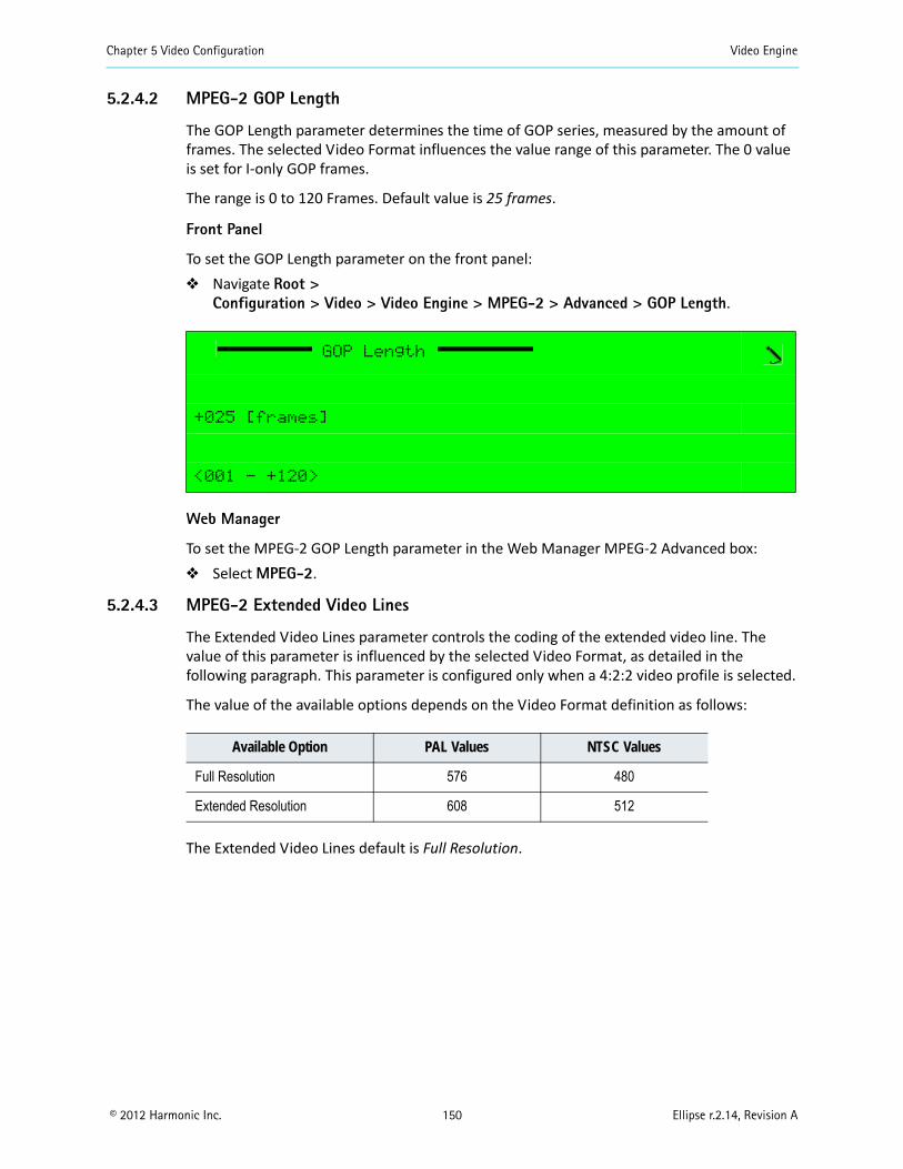
Chapter 5 Video Configuration Video Engine
© 2012 Harmonic Inc. 150 Ellipse r.2.14, Revision A
5.2.4.2 MPEG-2 GOP Length
The GOP Length parameter determines the time of GOP series, measured by the amount of frames. The selected Video Format influences the value range of this parameter. The 0 value is set for I-only GOP frames.
The range is 0 to 120 Frames. Default value is 25 frames.
Front Panel
To set the GOP Length parameter on the front panel: Navigate Root >
Configuration > Video > Video Engine > MPEG-2 > Advanced > GOP Length.
Web Manager
To set the MPEG-2 GOP Length parameter in the Web Manager MPEG-2 Advanced box: Select MPEG-2.
5.2.4.3 MPEG-2 Extended Video Lines
The Extended Video Lines parameter controls the coding of the extended video line. The value of this parameter is influenced by the selected Video Format, as detailed in the following paragraph. This parameter is configured only when a 4:2:2 video profile is selected.
The value of the available options depends on the Video Format definition as follows:
The Extended Video Lines default is Full Resolution.
GOP Length
+025 [frames]
<001 - +120>
Available Option PAL Values NTSC Values
Full Resolution 576 480
Extended Resolution 608 512
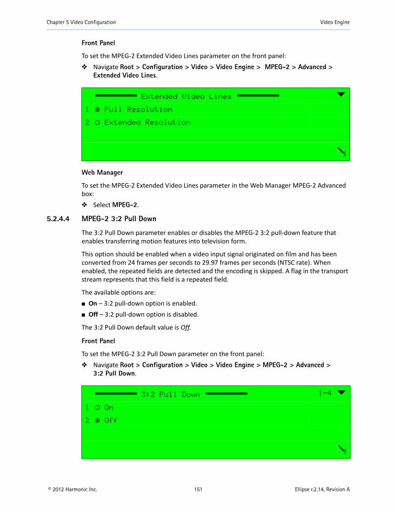
Chapter 5 Video Configuration Video Engine
© 2012 Harmonic Inc. 151 Ellipse r.2.14, Revision A
Front Panel
To set the MPEG-2 Extended Video Lines parameter on the front panel: Navigate Root > Configuration > Video > Video Engine > MPEG-2 > Advanced >
Extended Video Lines.
Web Manager
To set the MPEG-2 Extended Video Lines parameter in the Web Manager MPEG-2 Advanced box: Select MPEG-2.
5.2.4.4 MPEG-2 3:2 Pull Down
The 3:2 Pull Down parameter enables or disables the MPEG-2 3:2 pull-down feature that enables transferring motion features into television form.
This option should be enabled when a video input signal originated on film and has been converted from 24 frames per seconds to 29.97 frames per seconds (NTSC rate). When enabled, the repeated fields are detected and the encoding is skipped. A flag in the transport stream represents that this field is a repeated field.
The available options are: On – 3:2 pull-down option is enabled. Off – 3:2 pull-down option is disabled.
The 3:2 Pull Down default value is Off.
Front Panel
To set the MPEG-2 3:2 Pull Down parameter on the front panel: Navigate Root > Configuration > Video > Video Engine > MPEG-2 > Advanced >
3:2 Pull Down.
Extended Video Lines
1 ƒ Full Resolution
2 ‚ Extended Resolution
3:2 Pull Down 1-4
1 ‚ On
2 ƒ Off
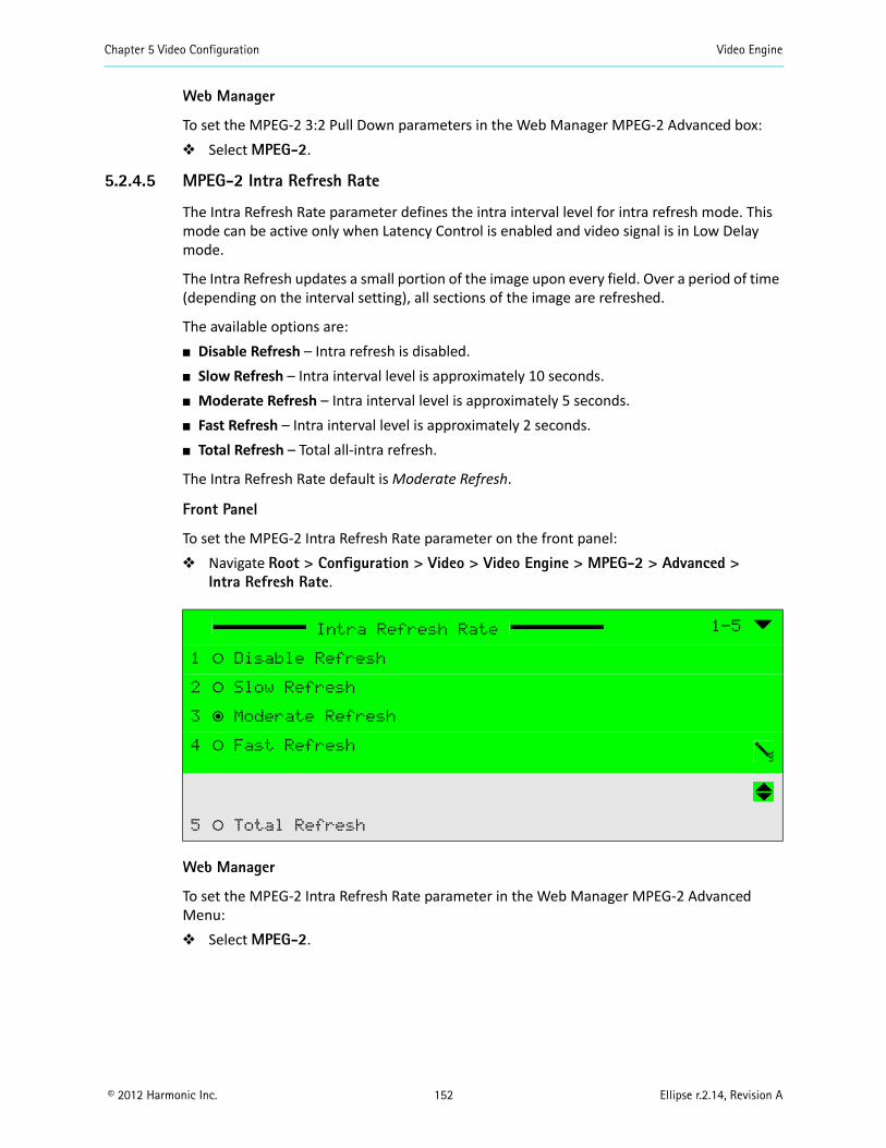
Chapter 5 Video Configuration Video Engine
© 2012 Harmonic Inc. 152 Ellipse r.2.14, Revision A
Web Manager
To set the MPEG-2 3:2 Pull Down parameters in the Web Manager MPEG-2 Advanced box: Select MPEG-2.
5.2.4.5 MPEG-2 Intra Refresh Rate
The Intra Refresh Rate parameter defines the intra interval level for intra refresh mode. This mode can be active only when Latency Control is enabled and video signal is in Low Delay mode.
The Intra Refresh updates a small portion of the image upon every field. Over a period of time (depending on the interval setting), all sections of the image are refreshed.
The available options are: Disable Refresh – Intra refresh is disabled. Slow Refresh – Intra interval level is approximately 10 seconds. Moderate Refresh – Intra interval level is approximately 5 seconds. Fast Refresh – Intra interval level is approximately 2 seconds. Total Refresh – Total all-intra refresh.
The Intra Refresh Rate default is Moderate Refresh.
Front Panel
To set the MPEG-2 Intra Refresh Rate parameter on the front panel: Navigate Root > Configuration > Video > Video Engine > MPEG-2 > Advanced >
Intra Refresh Rate.
Web Manager
To set the MPEG-2 Intra Refresh Rate parameter in the Web Manager MPEG-2 Advanced Menu: Select MPEG-2.
Intra Refresh Rate 1-5
1 ‚ Disable Refresh
2 ‚ Slow Refresh
3 ƒ Moderate Refresh
4 ‚ Fast Refresh
5 ‚ Total Refresh
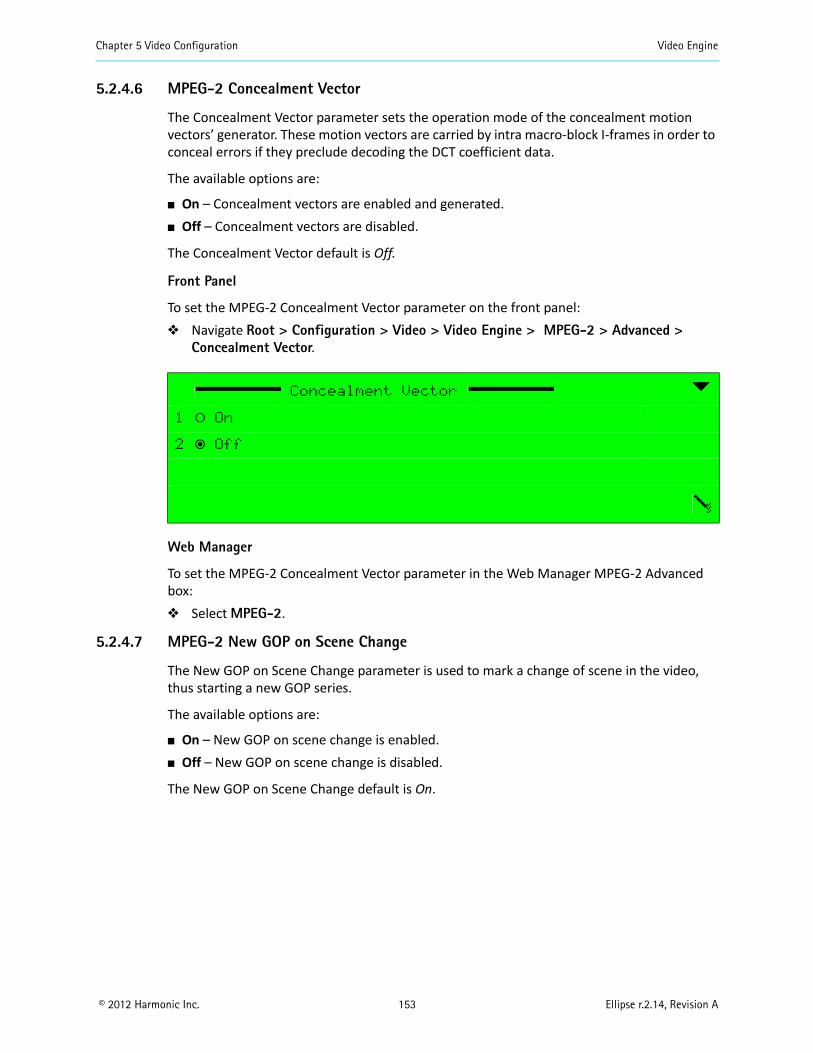
Chapter 5 Video Configuration Video Engine
© 2012 Harmonic Inc. 153 Ellipse r.2.14, Revision A
5.2.4.6 MPEG-2 Concealment Vector
The Concealment Vector parameter sets the operation mode of the concealment motion vectors’ generator. These motion vectors are carried by intra macro-block I-frames in order to conceal errors if they preclude decoding the DCT coefficient data.
The available options are:
On – Concealment vectors are enabled and generated. Off – Concealment vectors are disabled.
The Concealment Vector default is Off.
Front Panel
To set the MPEG-2 Concealment Vector parameter on the front panel: Navigate Root > Configuration > Video > Video Engine > MPEG-2 > Advanced >
Concealment Vector.
Web Manager
To set the MPEG-2 Concealment Vector parameter in the Web Manager MPEG-2 Advanced box: Select MPEG-2.
5.2.4.7 MPEG-2 New GOP on Scene Change
The New GOP on Scene Change parameter is used to mark a change of scene in the video, thus starting a new GOP series.
The available options are:
On – New GOP on scene change is enabled. Off – New GOP on scene change is disabled.
The New GOP on Scene Change default is On.
Concealment Vector
1 ‚ On
2 ƒ Off
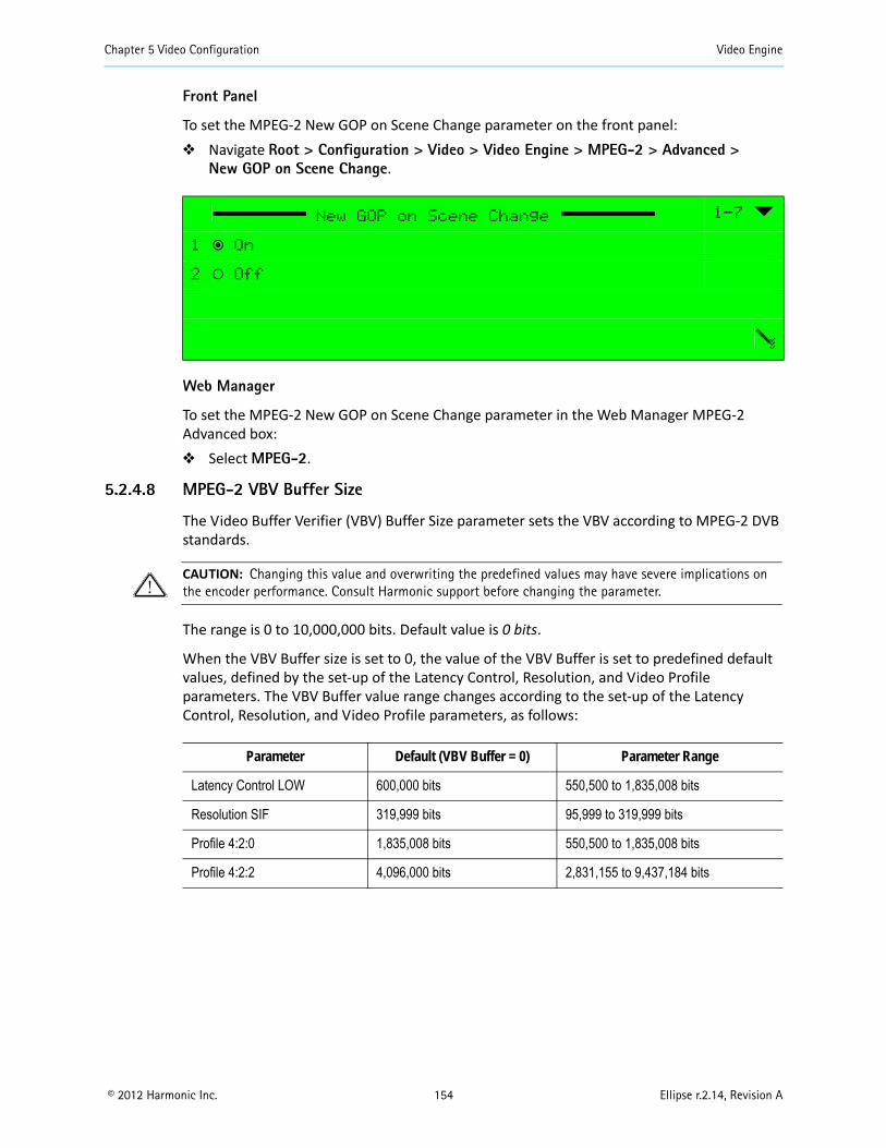
Chapter 5 Video Configuration Video Engine
© 2012 Harmonic Inc. 154 Ellipse r.2.14, Revision A
Front Panel
To set the MPEG-2 New GOP on Scene Change parameter on the front panel: Navigate Root > Configuration > Video > Video Engine > MPEG-2 > Advanced >
New GOP on Scene Change.
Web Manager
To set the MPEG-2 New GOP on Scene Change parameter in the Web Manager MPEG-2 Advanced box: Select MPEG-2.
5.2.4.8 MPEG-2 VBV Buffer Size
The Video Buffer Verifier (VBV) Buffer Size parameter sets the VBV according to MPEG-2 DVB standards.
CAUTION: Changing this value and overwriting the predefined values may have severe implications on the encoder performance. Consult Harmonic support before changing the parameter.
The range is 0 to 10,000,000 bits. Default value is 0 bits.
When the VBV Buffer size is set to 0, the value of the VBV Buffer is set to predefined default values, defined by the set-up of the Latency Control, Resolution, and Video Profile parameters. The VBV Buffer value range changes according to the set-up of the Latency Control, Resolution, and Video Profile parameters, as follows:
New GOP on Scene Change 1-7
1 ƒ On
2 ‚ Off
Parameter Default (VBV Buffer = 0) Parameter Range
Latency Control LOW 600,000 bits 550,500 to 1,835,008 bits
Resolution SIF 319,999 bits 95,999 to 319,999 bits
Profile 4:2:0 1,835,008 bits 550,500 to 1,835,008 bits
Profile 4:2:2 4,096,000 bits 2,831,155 to 9,437,184 bits
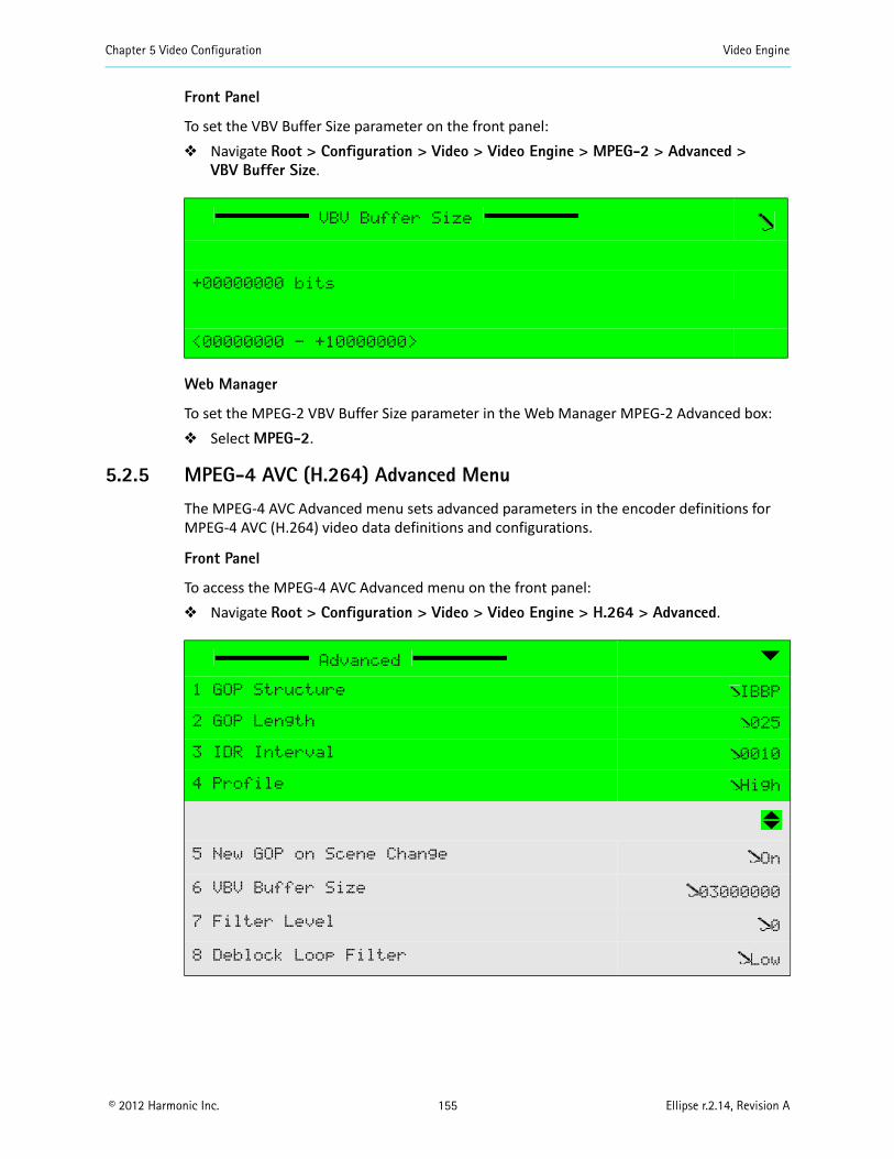
Chapter 5 Video Configuration Video Engine
© 2012 Harmonic Inc. 155 Ellipse r.2.14, Revision A
Front Panel
To set the VBV Buffer Size parameter on the front panel: Navigate Root > Configuration > Video > Video Engine > MPEG-2 > Advanced >
VBV Buffer Size.
Web Manager
To set the MPEG-2 VBV Buffer Size parameter in the Web Manager MPEG-2 Advanced box: Select MPEG-2.
5.2.5 MPEG-4 AVC (H.264) Advanced Menu
The MPEG-4 AVC Advanced menu sets advanced parameters in the encoder definitions for MPEG-4 AVC (H.264) video data definitions and configurations.
Front Panel
To access the MPEG-4 AVC Advanced menu on the front panel: Navigate Root > Configuration > Video > Video Engine > H.264 > Advanced.
VBV Buffer Size
+00000000 bits
<00000000 - +10000000>
Advanced
1 GOP Structure IBBP
2 GOP Length 025
3 IDR Interval 0010
4 Profile High
5 New GOP on Scene Change On
6 VBV Buffer Size 03000000
7 Filter Level 0
8 Deblock Loop Filter Low
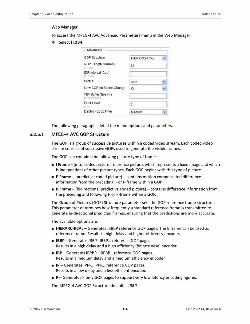
Chapter 5 Video Configuration Video Engine
© 2012 Harmonic Inc. 156 Ellipse r.2.14, Revision A
Web Manager
To access the MPEG-4 AVC Advanced Parameters menu in the Web Manager: Select H.264.
The following paragraphs detail the menu options and parameters.
5.2.5.1 MPEG-4 AVC GOP Structure
The GOP is a group of successive pictures within a coded video stream. Each coded video stream consists of successive GOPs used to generate the visible frames.
The GOP can contains the following picture type of frames:
I Frame – (intra coded picture) reference picture, which represents a fixed image and which is independent of other picture types. Each GOP begins with this type of picture.
P Frame – (predictive coded picture) – contains motion compensated difference information from the preceding I- or P-frame within a GOP.
B Frame – (bidirectional predictive coded picture) – contains difference information from the preceding and following I- or P-frame within a GOP.
The Group of Pictures (GOP) Structure parameter sets the GOP reference frame structure. This parameter determines how frequently a standard reference frame is transmitted to generate bi-directional predicted frames, ensuring that the predictions are more accurate.
The available options are: HIERARCHICAL – Generates IBBBP reference GOP pages. The B frame can be used as
reference frame. Results in high delay and higher efficiency encoder. IBBP – Generates IBBP...IBBP… reference GOP pages.
Results in a high delay and a high efficiency (bit rate wise) encoder. IBP – Generates IBPBP...IBPBP... reference GOP pages.
Results in a medium delay and a medium efficiency encoder. IP – Generates IPPP...IPPP... reference GOP pages.
Results in a low delay and a less efficient encoder. P – Generates P only GOP pages to support very low latency encoding figures.
The MPEG-4 AVC GOP Structure default is IBBP.
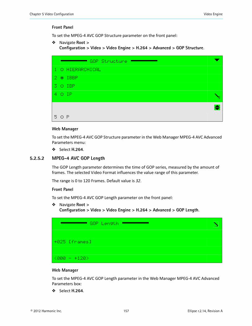
Chapter 5 Video Configuration Video Engine
© 2012 Harmonic Inc. 157 Ellipse r.2.14, Revision A
Front Panel
To set the MPEG-4 AVC GOP Structure parameter on the front panel: Navigate Root >
Configuration > Video > Video Engine > H.264 > Advanced > GOP Structure.
Web Manager
To set the MPEG-4 AVC GOP Structure parameter in the Web Manager MPEG-4 AVC Advanced Parameters menu: Select H.264.
5.2.5.2 MPEG-4 AVC GOP Length
The GOP Length parameter determines the time of GOP series, measured by the amount of frames. The selected Video Format influences the value range of this parameter.
The range is 0 to 120 Frames. Default value is 32.
Front Panel
To set the MPEG-4 AVC GOP Length parameter on the front panel: Navigate Root >
Configuration > Video > Video Engine > H.264 > Advanced > GOP Length.
Web Manager
To set the MPEG-4 AVC GOP Length parameter in the Web Manager MPEG-4 AVC Advanced Parameters box: Select H.264.
GOP Structure
1 ‚ HIERARCHICAL
2 ƒ IBBP
3 ‚ IBP
4 ‚ IP
5 ‚ P
GOP Length
+025 [frames]
<000 - +120>

Chapter 5 Video Configuration Video Engine
© 2012 Harmonic Inc. 158 Ellipse r.2.14, Revision A
5.2.5.3 MPEG-4 AVC GOP IDR Interval
The MPEG-4 AVC SD/HD Instantaneous Decoding Refresh (IDR) Interval parameter defines the number of GOPs interval where the IDR will appear.
The range is 0 to 1200 GOP. Default value is 10.
Front Panel
To set the MPEG-4 AVC IDR Interval parameter on the front panel: Navigate Root > Configuration > Video > Video Engine > H.264 > Advanced > IDR
Interval.
Web Manager
To set the MPEG-4 AVC SD/HD IDR Interval parameter in the Web Manager MPEG-4 AVC Advanced Parameters box: Select H.264.
5.2.5.4 MPEG-4 AVC SD/HD Profile
The MPEG-4 AVC default profile parameter sets the MPEG-4 AVC profile for SD/HD resolution.
The available options are:
Main – Mainstream consumer profile for broadcast and storage applications. High – The primary profile for broadcast and disc storage applications, particularly for high-
definition television applications. Auto – Automatic setup of the SD/HD profile.
The MPEG-4 AVC default profile is Auto.
Front Panel
To set the MPEG-4 AVC SD/HD Profile parameter on the front panel: Navigate Root > Configuration > Video > Video Engine > H.264 > Advanced > Profile.
IDR Interval
+0010 [GOP]
<0000 - +1200>
Profile
1 ƒ Main
2 ‚ High
3 ‚ Auto
4 ‚ Base Line
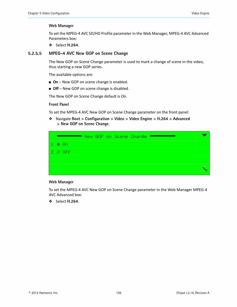
Chapter 5 Video Configuration Video Engine
© 2012 Harmonic Inc. 159 Ellipse r.2.14, Revision A
Web Manager
To set the MPEG-4 AVC SD/HD Profile parameter in the Web Manager, MPEG-4 AVC Advanced Parameters box: Select H.264.
5.2.5.5 MPEG-4 AVC New GOP on Scene Change
The New GOP on Scene Change parameter is used to mark a change of scene in the video, thus starting a new GOP series.
The available options are:
On – New GOP on scene change is enabled. Off – New GOP on scene change is disabled.
The New GOP on Scene Change default is On.
Front Panel
To set the MPEG-4 AVC New GOP on Scene Change parameter on the front panel: Navigate Root > Configuration > Video > Video Engine > H.264 > Advanced
> New GOP on Scene Change.
Web Manager
To set the MPEG-4 AVC New GOP on Scene Change parameter in the Web Manager MPEG-4 AVC Advanced box: Select H.264.
New GOP on Scene Change
1 ƒ On
2 ‚ Off
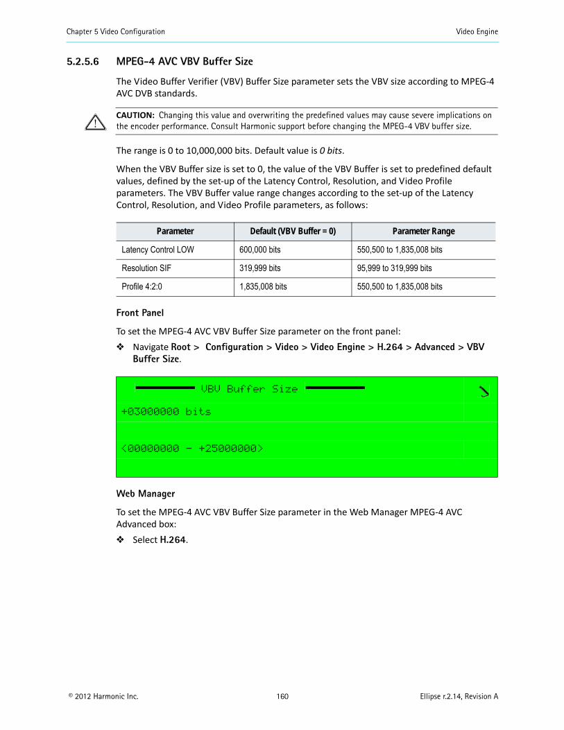
Chapter 5 Video Configuration Video Engine
© 2012 Harmonic Inc. 160 Ellipse r.2.14, Revision A
5.2.5.6 MPEG-4 AVC VBV Buffer Size
The Video Buffer Verifier (VBV) Buffer Size parameter sets the VBV size according to MPEG-4 AVC DVB standards.
CAUTION: Changing this value and overwriting the predefined values may cause severe implications on the encoder performance. Consult Harmonic support before changing the MPEG-4 VBV buffer size.
The range is 0 to 10,000,000 bits. Default value is 0 bits.
When the VBV Buffer size is set to 0, the value of the VBV Buffer is set to predefined default values, defined by the set-up of the Latency Control, Resolution, and Video Profile parameters. The VBV Buffer value range changes according to the set-up of the Latency Control, Resolution, and Video Profile parameters, as follows:
Front Panel
To set the MPEG-4 AVC VBV Buffer Size parameter on the front panel: Navigate Root > Configuration > Video > Video Engine > H.264 > Advanced > VBV
Buffer Size.
Web Manager
To set the MPEG-4 AVC VBV Buffer Size parameter in the Web Manager MPEG-4 AVC Advanced box: Select H.264.
Parameter Default (VBV Buffer = 0) Parameter Range
Latency Control LOW 600,000 bits 550,500 to 1,835,008 bits
Resolution SIF 319,999 bits 95,999 to 319,999 bits
Profile 4:2:0 1,835,008 bits 550,500 to 1,835,008 bits
VBV Buffer Size
+03000000 bits
<00000000 - +25000000>
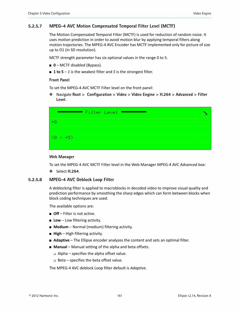
Chapter 5 Video Configuration Video Engine
© 2012 Harmonic Inc. 161 Ellipse r.2.14, Revision A
5.2.5.7 MPEG-4 AVC Motion Compensated Temporal Filter Level (MCTF)
The Motion Compensated Temporal Filter (MCTF) is used for reduction of random noise. It uses motion prediction in order to avoid motion blur by applying temporal filters along motion trajectories. The MPEG-4 AVC Encoder has MCTF implemented only for picture of size up to D1 (in SD resolution).
MCTF strength parameter has six optional values in the range 0 to 5.
0 – MCTF disabled (Bypass). 1 to 5 – 1 is the weakest filter and 5 is the strongest filter.
Front Panel
To set the MPEG-4 AVC MCTF Filter level on the front panel: Navigate Root > Configuration > Video > Video Engine > H.264 > Advanced > Filter
Level.
Web Manager
To set the MPEG-4 AVC MCTF Filter level in the Web Manager MPEG-4 AVC Advanced box: Select H.264.
5.2.5.8 MPEG-4 AVC Deblock Loop Filter
A deblocking filter is applied to macroblocks in decoded video to improve visual quality and prediction performance by smoothing the sharp edges which can form between blocks when block coding techniques are used.
The available options are:
Off – Filter is not active. Low – Low filtering activity. Medium – Normal (medium) filtering activity. High – High filtering activity. Adaptive – The Ellipse encoder analyzes the content and sets an optimal filter. Manual – Manual setting of the alpha and beta offsets.
Alpha – specifies the alpha offset value. Beta – specifies the beta offset value.
The MPEG-4 AVC deblock Loop filter default is Adaptive.
Filter Level
+0
<0 - +5>
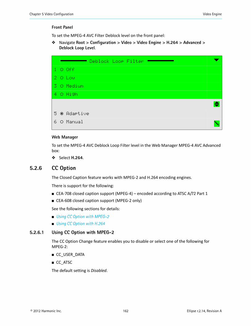
Chapter 5 Video Configuration Video Engine
© 2012 Harmonic Inc. 162 Ellipse r.2.14, Revision A
Front Panel
To set the MPEG-4 AVC Filter Deblock level on the front panel: Navigate Root > Configuration > Video > Video Engine > H.264 > Advanced >
Deblock Loop Level.
Web Manager
To set the MPEG-4 AVC Deblock Loop Filter level in the Web Manager MPEG-4 AVC Advanced box: Select H.264.
5.2.6 CC Option
The Closed Caption feature works with MPEG-2 and H.264 encoding engines.
There is support for the following:
CEA-708 closed caption support (MPEG-4) – encoded according to ATSC A/72 Part 1 CEA-608 closed caption support (MPEG-2 only)
See the following sections for details:
Using CC Option with MPEG-2
Using CC Option with H.264
5.2.6.1 Using CC Option with MPEG-2
The CC Option Change feature enables you to disable or select one of the following for MPEG-2:
CC_USER_DATA
CC_ATSC
The default setting is Disabled.
Deblock Loop Filter
1 ‚ Off
2 ‚ Low
3 ‚ Medium
4 ‚ High
5 ƒ Adaptive
6 ‚ Manual
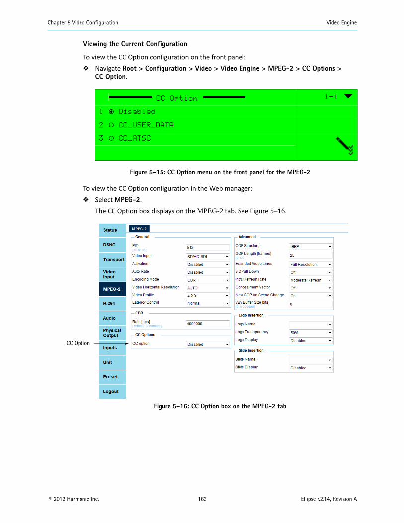
Chapter 5 Video Configuration Video Engine
© 2012 Harmonic Inc. 163 Ellipse r.2.14, Revision A
Viewing the Current Configuration
To view the CC Option configuration on the front panel: Navigate Root > Configuration > Video > Video Engine > MPEG-2 > CC Options >
CC Option.
Figure 5–15: CC Option menu on the front panel for the MPEG-2
To view the CC Option configuration in the Web manager: Select MPEG-2.
The CC Option box displays on the MPEG-2 tab. See Figure 5–16.
Figure 5–16: CC Option box on the MPEG-2 tab
CC Option 1-1
1 ƒ Disabled
2 ‚ CC_USER_DATA
3 ‚ CC_ATSC
CC Option
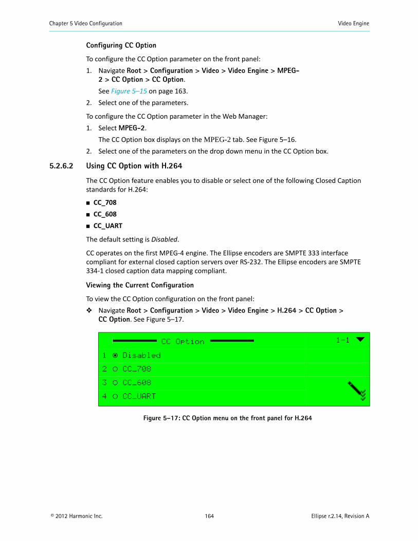
Chapter 5 Video Configuration Video Engine
© 2012 Harmonic Inc. 164 Ellipse r.2.14, Revision A
Configuring CC Option
To configure the CC Option parameter on the front panel:1. Navigate Root > Configuration > Video > Video Engine > MPEG-
2 > CC Option > CC Option.See Figure 5–15 on page 163.
2. Select one of the parameters.
To configure the CC Option parameter in the Web Manager:1. Select MPEG-2.
The CC Option box displays on the MPEG-2 tab. See Figure 5–16.2. Select one of the parameters on the drop down menu in the CC Option box.
5.2.6.2 Using CC Option with H.264
The CC Option feature enables you to disable or select one of the following Closed Caption standards for H.264:
CC_708 CC_608 CC_UART
The default setting is Disabled.
CC operates on the first MPEG-4 engine. The Ellipse encoders are SMPTE 333 interface compliant for external closed caption servers over RS-232. The Ellipse encoders are SMPTE 334-1 closed caption data mapping compliant.
Viewing the Current Configuration
To view the CC Option configuration on the front panel: Navigate Root > Configuration > Video > Video Engine > H.264 > CC Option >
CC Option. See Figure 5–17.
Figure 5–17: CC Option menu on the front panel for H.264
CC Option 1-1
1 ƒ Disabled
2 ‚ CC_708
3 ‚ CC_608
4 ‚ CC_UART
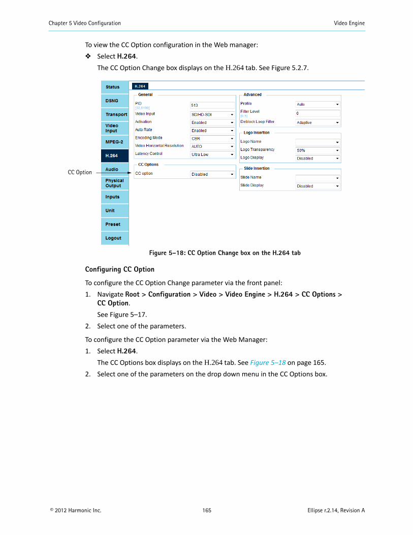
Chapter 5 Video Configuration Video Engine
© 2012 Harmonic Inc. 165 Ellipse r.2.14, Revision A
To view the CC Option configuration in the Web manager: Select H.264.
The CC Option Change box displays on the H.264 tab. See Figure 5.2.7.
Figure 5–18: CC Option Change box on the H.264 tab
Configuring CC Option
To configure the CC Option Change parameter via the front panel:1. Navigate Root > Configuration > Video > Video Engine > H.264 > CC Options >
CC Option.See Figure 5–17.
2. Select one of the parameters.
To configure the CC Option parameter via the Web Manager:1. Select H.264.
The CC Options box displays on the H.264 tab. See Figure 5–18 on page 165.2. Select one of the parameters on the drop down menu in the CC Options box.
CC Option
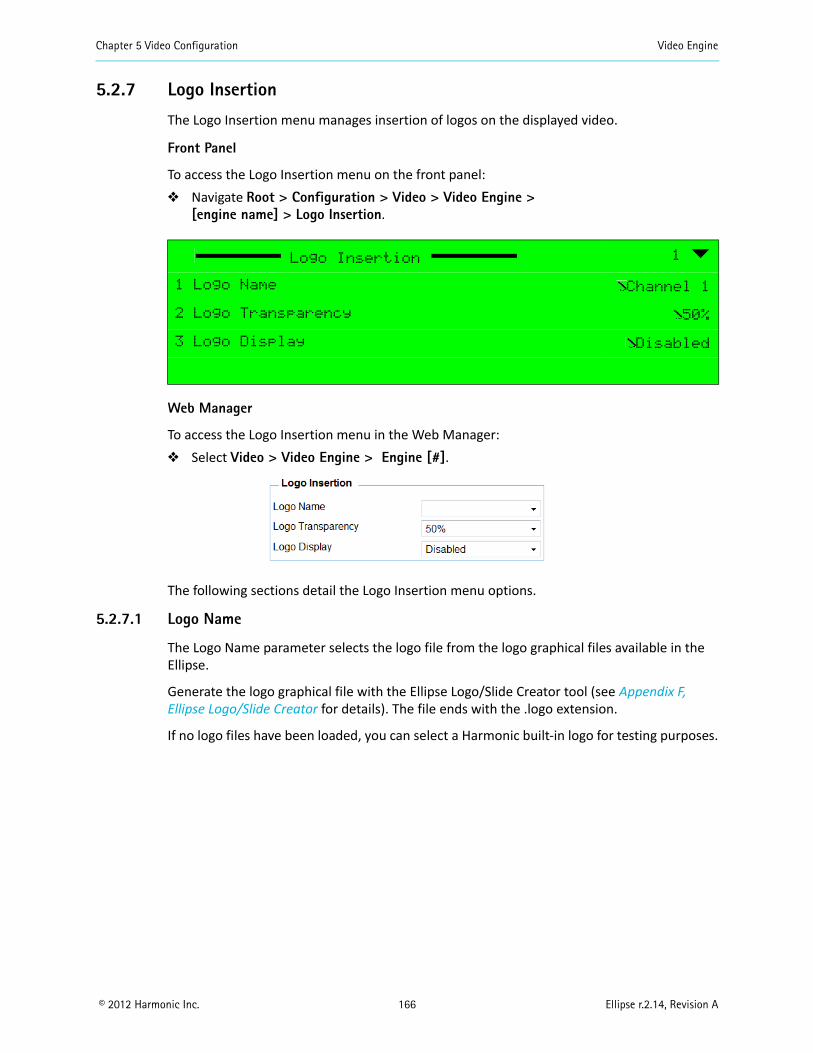
Chapter 5 Video Configuration Video Engine
© 2012 Harmonic Inc. 166 Ellipse r.2.14, Revision A
5.2.7 Logo Insertion
The Logo Insertion menu manages insertion of logos on the displayed video.
Front Panel
To access the Logo Insertion menu on the front panel: Navigate Root > Configuration > Video > Video Engine >
[engine name] > Logo Insertion.
Web Manager
To access the Logo Insertion menu in the Web Manager: Select Video > Video Engine > Engine [#].
The following sections detail the Logo Insertion menu options.
5.2.7.1 Logo Name
The Logo Name parameter selects the logo file from the logo graphical files available in the Ellipse.
Generate the logo graphical file with the Ellipse Logo/Slide Creator tool (see Appendix F, Ellipse Logo/Slide Creator for details). The file ends with the .logo extension.
If no logo files have been loaded, you can select a Harmonic built-in logo for testing purposes.
Logo Insertion 1
1 Logo Name Channel 1
2 Logo Transparency 50%
3 Logo Display Disabled
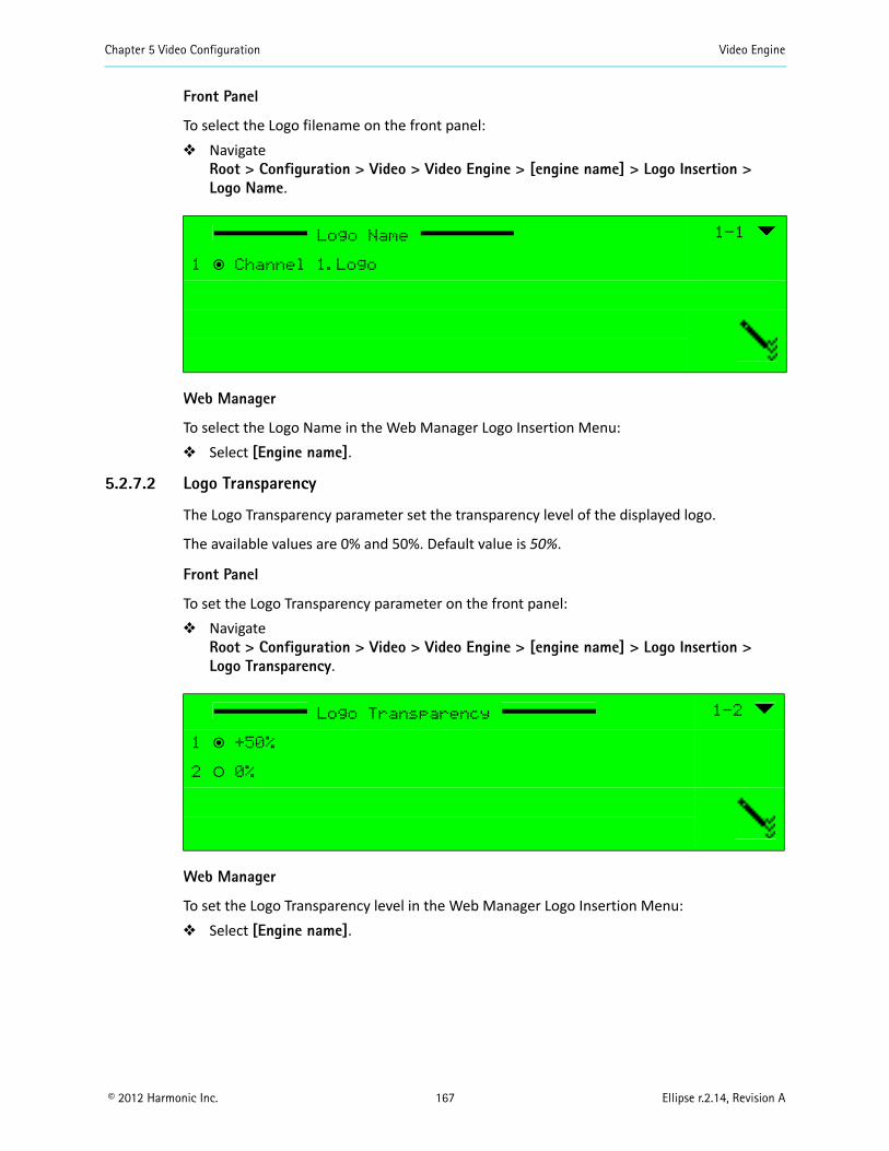
Chapter 5 Video Configuration Video Engine
© 2012 Harmonic Inc. 167 Ellipse r.2.14, Revision A
Front Panel
To select the Logo filename on the front panel: Navigate
Root > Configuration > Video > Video Engine > [engine name] > Logo Insertion > Logo Name.
Web Manager
To select the Logo Name in the Web Manager Logo Insertion Menu: Select [Engine name].
5.2.7.2 Logo Transparency
The Logo Transparency parameter set the transparency level of the displayed logo.
The available values are 0% and 50%. Default value is 50%.
Front Panel
To set the Logo Transparency parameter on the front panel: Navigate
Root > Configuration > Video > Video Engine > [engine name] > Logo Insertion >Logo Transparency.
Web Manager
To set the Logo Transparency level in the Web Manager Logo Insertion Menu: Select [Engine name].
Logo Name 1-1
1 ƒ Channel 1.Logo
Logo Transparency 1-2
1 ƒ +50%
2 ‚ 0%
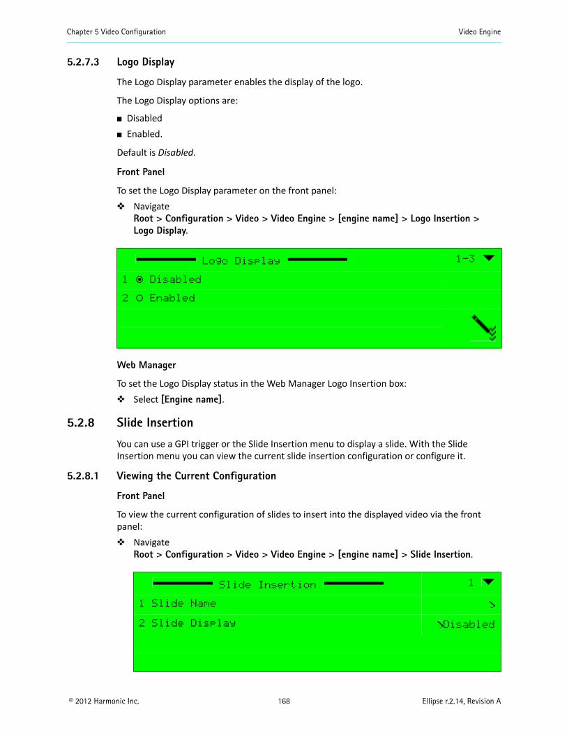
Chapter 5 Video Configuration Video Engine
© 2012 Harmonic Inc. 168 Ellipse r.2.14, Revision A
5.2.7.3 Logo Display
The Logo Display parameter enables the display of the logo.
The Logo Display options are:
Disabled Enabled.
Default is Disabled.
Front Panel
To set the Logo Display parameter on the front panel: Navigate
Root > Configuration > Video > Video Engine > [engine name] > Logo Insertion >Logo Display.
Web Manager
To set the Logo Display status in the Web Manager Logo Insertion box: Select [Engine name].
5.2.8 Slide Insertion
You can use a GPI trigger or the Slide Insertion menu to display a slide. With the Slide Insertion menu you can view the current slide insertion configuration or configure it.
5.2.8.1 Viewing the Current Configuration
Front Panel
To view the current configuration of slides to insert into the displayed video via the front panel: Navigate
Root > Configuration > Video > Video Engine > [engine name] > Slide Insertion.
Logo Display 1-3
1 ƒ Disabled
2 ‚ Enabled
Slide Insertion 1
1 Slide Name
2 Slide Display Disabled
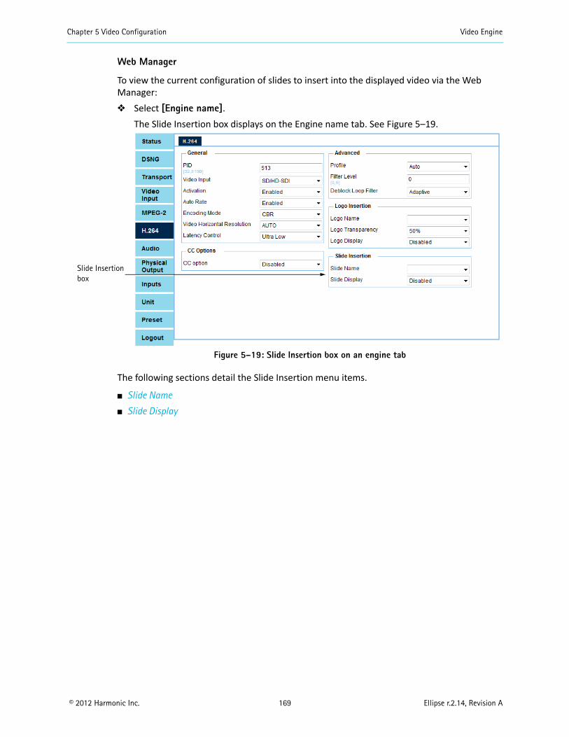
Chapter 5 Video Configuration Video Engine
© 2012 Harmonic Inc. 169 Ellipse r.2.14, Revision A
Web Manager
To view the current configuration of slides to insert into the displayed video via the Web Manager: Select [Engine name].
The Slide Insertion box displays on the Engine name tab. See Figure 5–19.
Figure 5–19: Slide Insertion box on an engine tab
The following sections detail the Slide Insertion menu items.
Slide Name
Slide Display
Slide Insertionbox
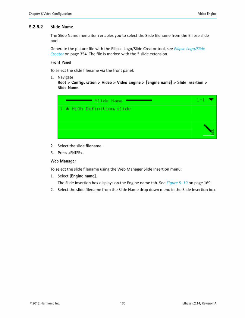
Chapter 5 Video Configuration Video Engine
© 2012 Harmonic Inc. 170 Ellipse r.2.14, Revision A
5.2.8.2 Slide Name
The Slide Name menu item enables you to select the Slide filename from the Ellipse slide pool.
Generate the picture file with the Ellipse Logo/Slide Creator tool, see Ellipse Logo/Slide Creator on page 354. The file is marked with the *.slide extension.
Front Panel
To select the slide filename via the front panel:1. Navigate
Root > Configuration > Video > Video Engine > [engine name] > Slide Insertion > Slide Name.
2. Select the slide filename.3. Press <ENTER>.
Web Manager
To select the slide filename using the Web Manager Slide Insertion menu:1. Select [Engine name].
The Slide Insertion box displays on the Engine name tab. See Figure 5–19 on page 169.2. Select the slide filename from the Slide Name drop down menu in the Slide Insertion box.
Slide Name 1-1
1 ƒ High Definition.slide
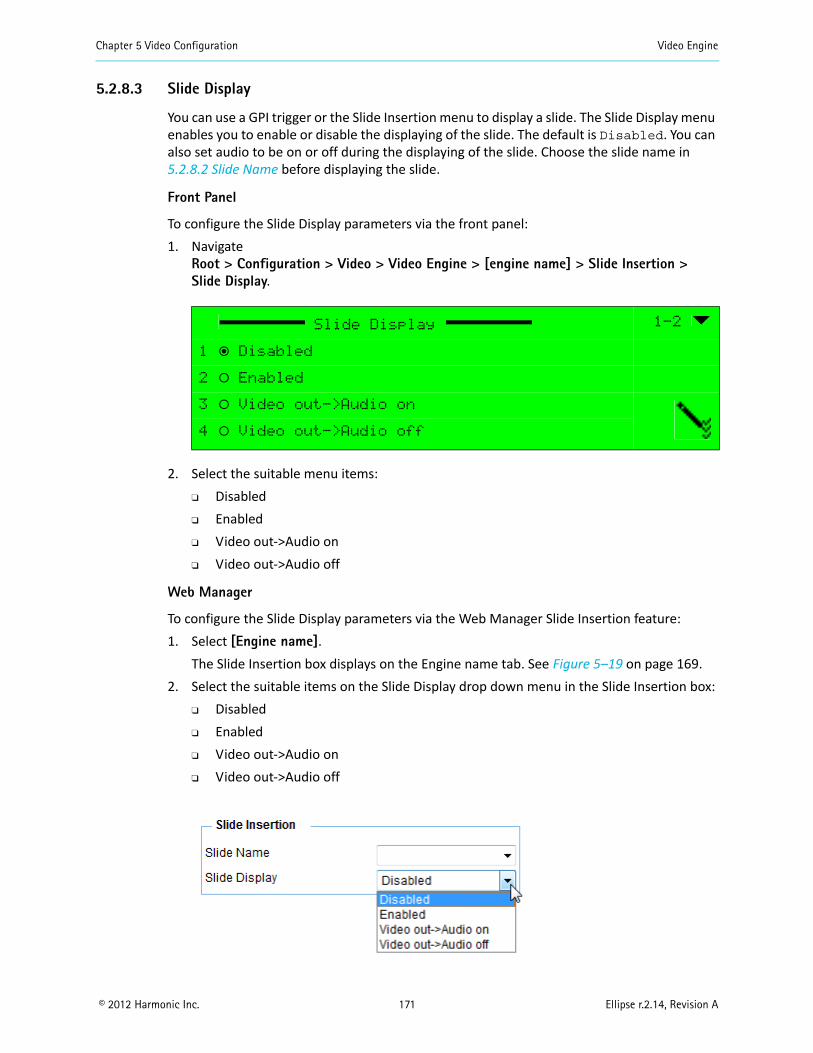
Chapter 5 Video Configuration Video Engine
© 2012 Harmonic Inc. 171 Ellipse r.2.14, Revision A
5.2.8.3 Slide Display
You can use a GPI trigger or the Slide Insertion menu to display a slide. The Slide Display menu enables you to enable or disable the displaying of the slide. The default is Disabled. You can also set audio to be on or off during the displaying of the slide. Choose the slide name in 5.2.8.2 Slide Name before displaying the slide.
Front Panel
To configure the Slide Display parameters via the front panel:1. Navigate
Root > Configuration > Video > Video Engine > [engine name] > Slide Insertion >Slide Display.
2. Select the suitable menu items: Disabled Enabled Video out->Audio on Video out->Audio off
Web Manager
To configure the Slide Display parameters via the Web Manager Slide Insertion feature:1. Select [Engine name].
The Slide Insertion box displays on the Engine name tab. See Figure 5–19 on page 169.2. Select the suitable items on the Slide Display drop down menu in the Slide Insertion box:
Disabled Enabled Video out->Audio on Video out->Audio off
Slide Display 1-2
1 ƒ Disabled
2 ‚ Enabled
3 ‚ Video out->Audio on
4 ‚ Video out->Audio off
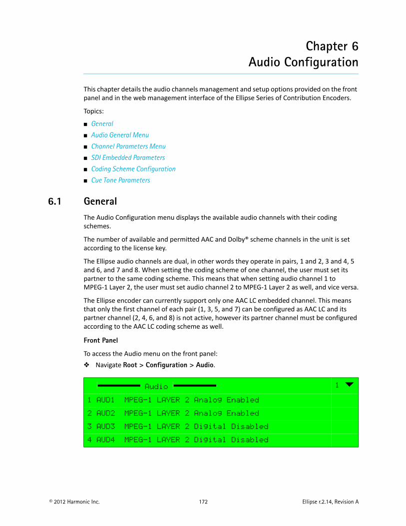
© 2012 Harmonic Inc. 172 Ellipse r.2.14, Revision A
Chapter 6Audio Configuration
This chapter details the audio channels management and setup options provided on the front panel and in the web management interface of the Ellipse Series of Contribution Encoders.
Topics:
General
Audio General Menu
Channel Parameters Menu
SDI Embedded Parameters
Coding Scheme Configuration
Cue Tone Parameters
6.1 GeneralThe Audio Configuration menu displays the available audio channels with their coding schemes.
The number of available and permitted AAC and Dolby® scheme channels in the unit is set according to the license key.
The Ellipse audio channels are dual, in other words they operate in pairs, 1 and 2, 3 and 4, 5 and 6, and 7 and 8. When setting the coding scheme of one channel, the user must set its partner to the same coding scheme. This means that when setting audio channel 1 to MPEG-1 Layer 2, the user must set audio channel 2 to MPEG-1 Layer 2 as well, and vice versa.
The Ellipse encoder can currently support only one AAC LC embedded channel. This means that only the first channel of each pair (1, 3, 5, and 7) can be configured as AAC LC and its partner channel (2, 4, 6, and 8) is not active, however its partner channel must be configured according to the AAC LC coding scheme as well.
Front Panel
To access the Audio menu on the front panel: Navigate Root > Configuration > Audio.
Audio 1
1 AUD1 MPEG-1 LAYER 2 Analog Enabled
2 AUD2 MPEG-1 LAYER 2 Analog Enabled
3 AUD3 MPEG-1 LAYER 2 Digital Disabled
4 AUD4 MPEG-1 LAYER 2 Digital Disabled
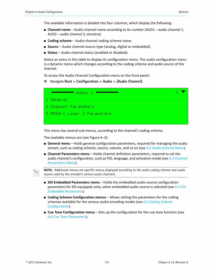
Chapter 6 Audio Configuration General
© 2012 Harmonic Inc. 173 Ellipse r.2.14, Revision A
The available information is divided into four columns, which display the following:
Channel name – Audio channel name according to its number (AUD1 – audio channel 1, AUD2 – audio channel 2, etcetera).
Coding scheme – Audio channel coding scheme name. Source – Audio channel source type (analog, digital or embedded). Status – Audio channel status (enabled or disabled).
Select an entry in this table to display its configuration menu. The audio configuration menu is a dynamic menu which changes according to the coding scheme and audio source of the channel.
To access the Audio Channel Configuration menu on the front panel: Navigate Root > Configuration > Audio > [Audio Channel].
This menu has several sub-menus, according to the channel’s coding scheme.
The available menus are (see Figure 6–2): General menu – Holds general configuration parameters, required for managing the audio
stream, such as coding scheme, source, volume, and so on (see 6.2 Audio General Menu). Channel Parameters menu – Holds channel definition parameters, required to set the
audio channel’s configuration, such as PID, language, and activation mode (see 6.3 Channel Parameters Menu).
NOTE: Additional menus are specific menus displayed according to the audio coding scheme and audio source used by the encoder’s various audio channels.
SDI Embedded Parameters menu – Holds the embedded audio-source configuration parameters for SDI equipped units, when embedded audio source is selected (see 6.4 SDI Embedded Parameters).
Coding Scheme Configuration menus – Allows setting the parameters for the coding schemes available for the various audio encoding modes (see 6.5 Coding Scheme Configuration).
Cue Tone Configuration menu – Sets up the configuration for the cue tone function (see 6.6 Cue Tone Parameters).
Audio 1 1
1 General
2 Channel Parameters
3 MPEG-1 Layer 2 Parameters
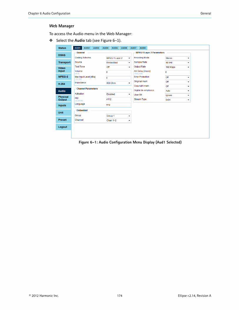
Chapter 6 Audio Configuration General
© 2012 Harmonic Inc. 174 Ellipse r.2.14, Revision A
Web Manager
To access the Audio menu in the Web Manager: Select the Audio tab (see Figure 6–1).
Figure 6–1: Audio Configuration Menu Display (Aud1 Selected)
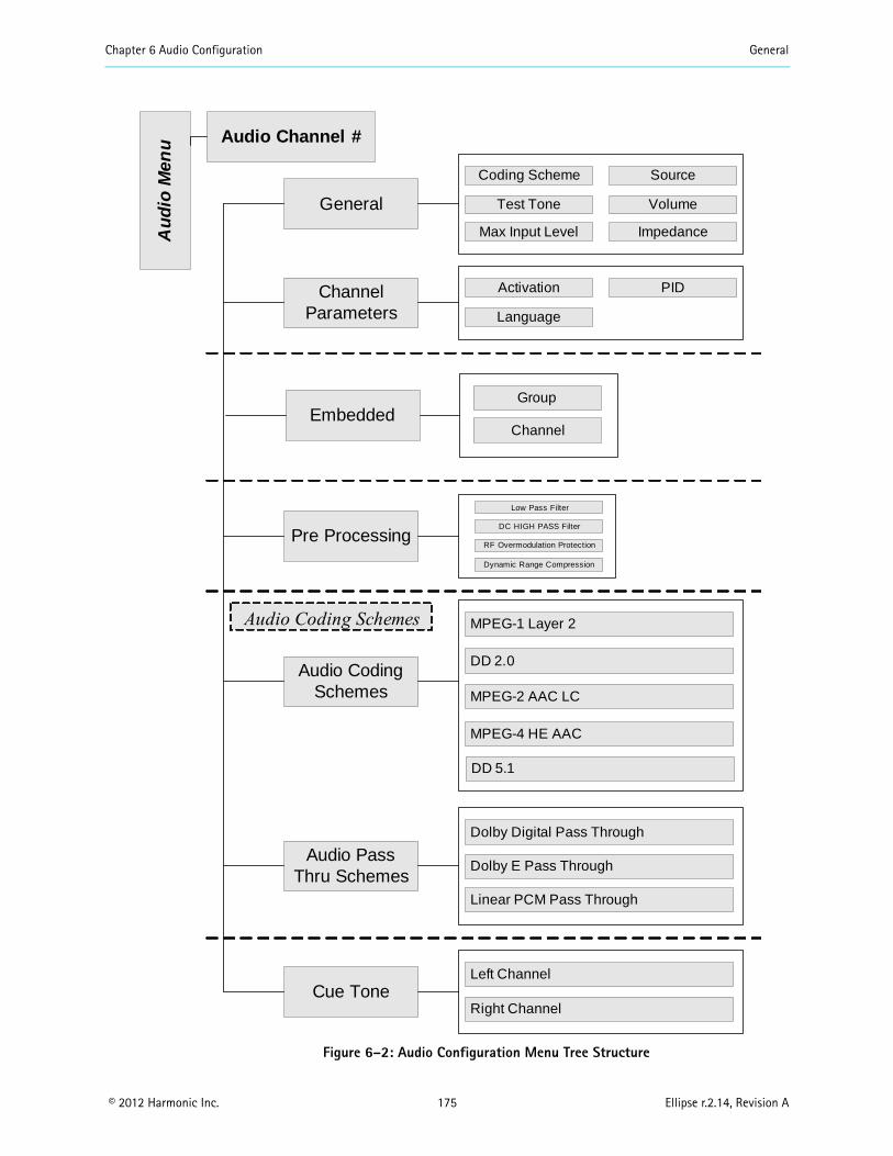
Chapter 6 Audio Configuration General
© 2012 Harmonic Inc. 175 Ellipse r.2.14, Revision A
Figure 6–2: Audio Configuration Menu Tree Structure
Au
dio
Men
u
General
Audio Channel #
Channel Parameters
ImpedanceMax Input Level
SourceCoding Scheme
VolumeTest Tone
PIDActivation
Language
Audio Coding Schemes
MPEG-1 Layer 2
DD 2.0
MPEG-2 AAC LC
MPEG-4 HE AAC
Audio Pass Thru Schemes
Dolby Digital Pass Through
Dolby E Pass Through
Cue ToneLeft Channel
Right Channel
Linear PCM Pass Through
Audio Coding Schemes
EmbeddedGroup
Channel
DD 5.1
Pre Processing
Low Pass Filter
DC HIGH PASS Filter
RF Overmodulation Protection
Dynamic Range Compression
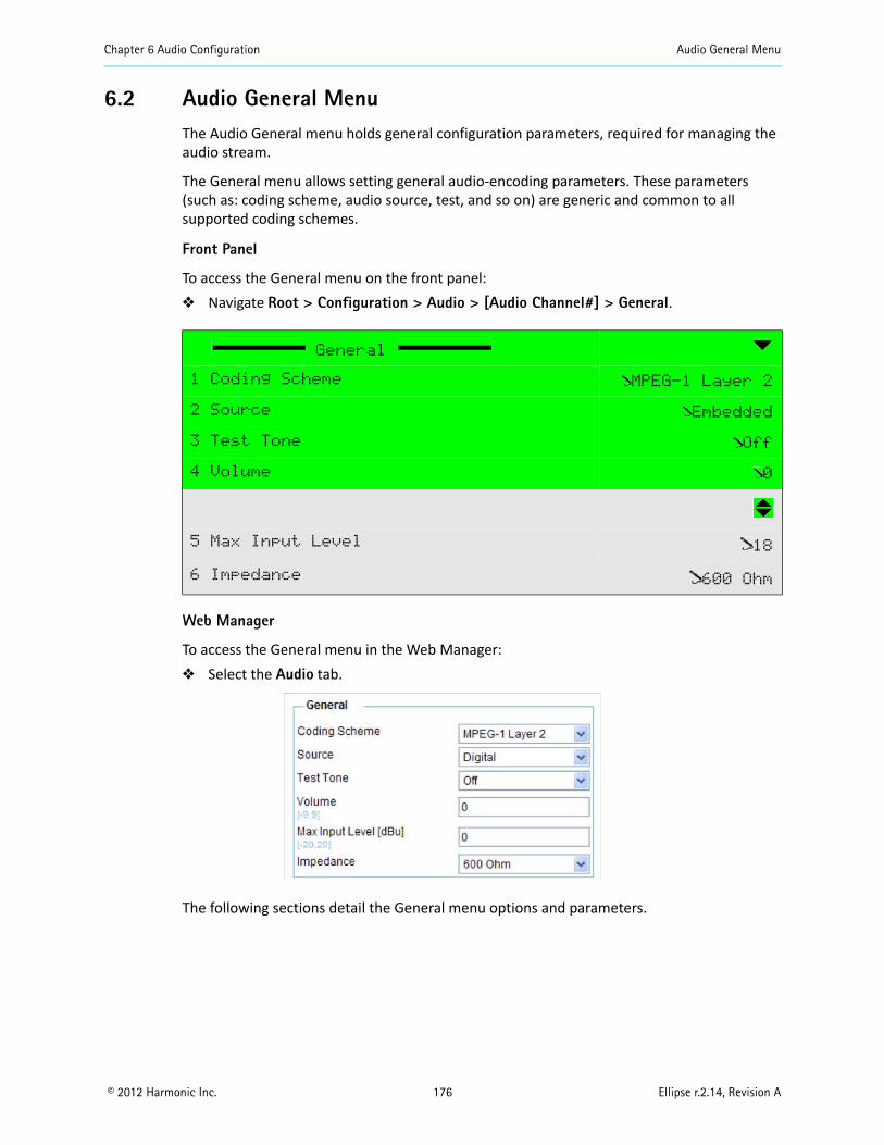
Chapter 6 Audio Configuration Audio General Menu
© 2012 Harmonic Inc. 176 Ellipse r.2.14, Revision A
6.2 Audio General MenuThe Audio General menu holds general configuration parameters, required for managing the audio stream.
The General menu allows setting general audio-encoding parameters. These parameters (such as: coding scheme, audio source, test, and so on) are generic and common to all supported coding schemes.
Front Panel
To access the General menu on the front panel: Navigate Root > Configuration > Audio > [Audio Channel#] > General.
Web Manager
To access the General menu in the Web Manager: Select the Audio tab.
The following sections detail the General menu options and parameters.
General
1 Coding Scheme MPEG-1 Layer 2
2 Source Embedded
3 Test Tone Off
4 Volume 0
5 Max Input Level 18
6 Impedance 600 Ohm
Chapter 6 Audio Configuration Audio General Menu
© 2012 Harmonic Inc. 177 Ellipse r.2.14, Revision A
6.2.1 Coding Scheme
The Coding Scheme parameter allows setting the coding scheme of the audio channel. Selecting a coding scheme – MPEG-1 Layer 2, Dolby Digital, AAC LC, or a pass through coding scheme—enables the configuration menu suitable for that coding scheme.
NOTE: Before setting the coding scheme, the user must set the Activation mode of the audio channel to Disabled.On the front panel, any changes last only 60 seconds while the Warning LED blinks. Therefore, when setting a new coding scheme, for the change to be permanent or last longer the user must save the change (press F1, for details, see 2.1.1.3 Front Panel Save Menu on page 24).
NOTE: Due to the complexity and wide diversity of the Coding Schemes provided by the Ellipse Contribution Encoders, a full detailed description is provided in 6.5 Coding Scheme Configuration on page 191.
The available options are: MPEG-1 Layer 2 (Default option) – Sets the coding scheme of the audio channel to MPEG-1
Layer 2 analog, enabling the Musicam Configuration menu. See 6.5.1 MPEG-1 Layer 2 Parameters.
DD 2.0 – Sets the coding scheme of the audio channel to Dolby Digital 2.0, enabling the Dolby Digital 2.0 Configuration menu. See 6.5.2 Dolby Digital 2.0 Parameters and 6.5.3 Dolby Digital 2.0 and Dolby Digital 5.1 Pre-Processing.
MPEG-2 AAC LC – Sets the coding scheme of the audio to embedded MPEG-2 AAC LC (Advance Audio Coding – Low Complexity), enabling the MPEG-2 AAC LC Configuration menu. See 6.5.4 MPEG-2 AAC LC Parameters.
DD Pass Through – Sets the coding scheme of the audio to Dolby Digital pass-through, enabling the Dolby Digital Pass Through Configuration menu. See 6.5.7 Dolby Digital Pass Through Parameters.
Dolby E pass through – Sets the coding scheme of the audio to Dolby E pass through, enabling the Dolby E Pass Through Configuration menu. See 6.5.8 Dolby E Pass Through Parameters Menu.
Linear PCM pass through – Sets the coding scheme of the audio to Linear PCM pass through (Pulse Code Modulation), enabling the Linear PCM Configuration menu. See 6.5.9 Linear PCM Pass Through Parameters Menu.
MPEG-4 HE AAC – Sets the MPEG-4 HE AAC (Advance Audio Coding - High Efficiency) is a lossy data compression scheme for digital audio. It is an extension of MPEG-2 AAC LC optimized for MPEG-4 low-bitrate applications such as streaming audio. See 6.5.5 MPEG-4 HE AAC Parameters.
Cue Tone – Sets the Cue Tone parameters. See 6.6 Cue Tone Parameters. DD 5.1 – See 6.5.6 Dolby Digital 5.1.
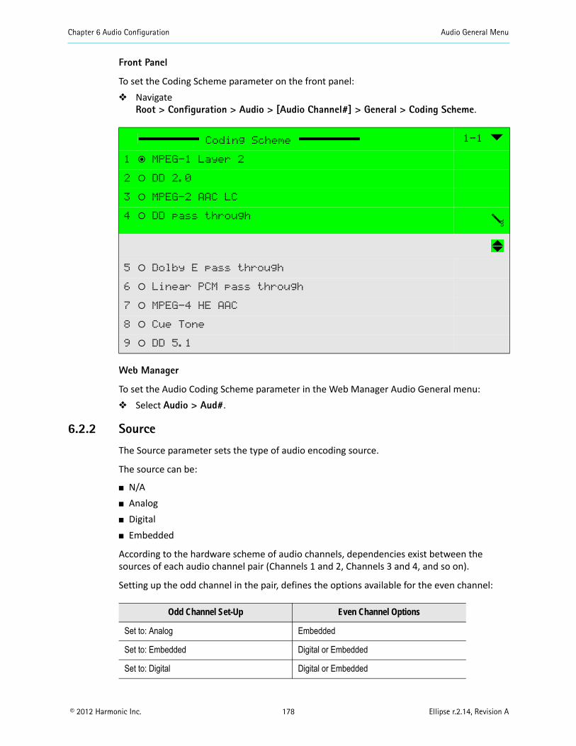
Chapter 6 Audio Configuration Audio General Menu
© 2012 Harmonic Inc. 178 Ellipse r.2.14, Revision A
Front Panel
To set the Coding Scheme parameter on the front panel: Navigate
Root > Configuration > Audio > [Audio Channel#] > General > Coding Scheme.
Web Manager
To set the Audio Coding Scheme parameter in the Web Manager Audio General menu: Select Audio > Aud#.
6.2.2 Source
The Source parameter sets the type of audio encoding source.
The source can be:
N/A Analog Digital Embedded
According to the hardware scheme of audio channels, dependencies exist between the sources of each audio channel pair (Channels 1 and 2, Channels 3 and 4, and so on).
Setting up the odd channel in the pair, defines the options available for the even channel:
Coding Scheme 1-1
1 ƒ MPEG-1 Layer 2
2 ‚ DD 2.0
3 ‚ MPEG-2 AAC LC
4 ‚ DD pass through
5 ‚ Dolby E pass through
6 ‚ Linear PCM pass through
7 ‚ MPEG-4 HE AAC
8 ‚ Cue Tone
9 ‚ DD 5.1
Odd Channel Set-Up Even Channel Options
Set to: Analog Embedded
Set to: Embedded Digital or Embedded
Set to: Digital Digital or Embedded
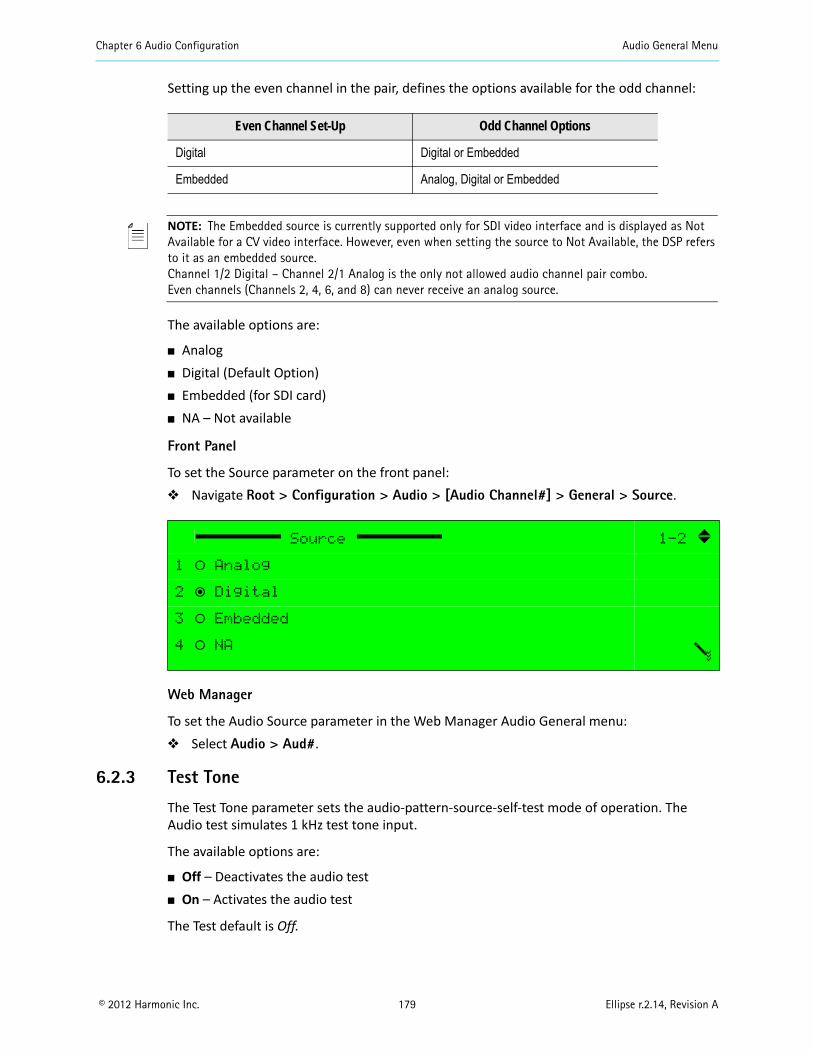
Chapter 6 Audio Configuration Audio General Menu
© 2012 Harmonic Inc. 179 Ellipse r.2.14, Revision A
Setting up the even channel in the pair, defines the options available for the odd channel:
NOTE: The Embedded source is currently supported only for SDI video interface and is displayed as Not Available for a CV video interface. However, even when setting the source to Not Available, the DSP refers to it as an embedded source.Channel 1/2 Digital – Channel 2/1 Analog is the only not allowed audio channel pair combo.Even channels (Channels 2, 4, 6, and 8) can never receive an analog source.
The available options are:
Analog Digital (Default Option) Embedded (for SDI card) NA – Not available
Front Panel
To set the Source parameter on the front panel: Navigate Root > Configuration > Audio > [Audio Channel#] > General > Source.
Web Manager
To set the Audio Source parameter in the Web Manager Audio General menu: Select Audio > Aud#.
6.2.3 Test Tone
The Test Tone parameter sets the audio-pattern-source-self-test mode of operation. The Audio test simulates 1 kHz test tone input.
The available options are:
Off – Deactivates the audio test On – Activates the audio test
The Test default is Off.
Even Channel Set-Up Odd Channel Options
Digital Digital or Embedded
Embedded Analog, Digital or Embedded
Source 1-2
1 ‚ Analog
2 ƒ Digital
3 ‚ Embedded
4 ‚ NA
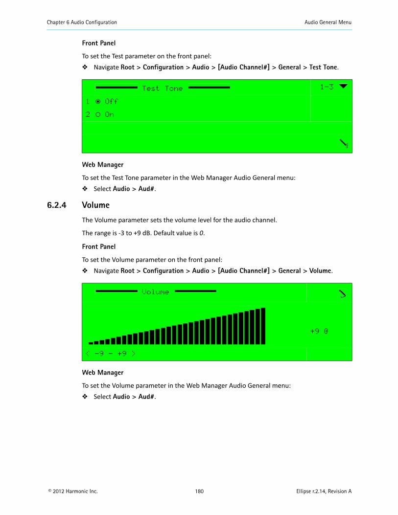
Chapter 6 Audio Configuration Audio General Menu
© 2012 Harmonic Inc. 180 Ellipse r.2.14, Revision A
Front Panel
To set the Test parameter on the front panel: Navigate Root > Configuration > Audio > [Audio Channel#] > General > Test Tone.
Web Manager
To set the Test Tone parameter in the Web Manager Audio General menu: Select Audio > Aud#.
6.2.4 Volume
The Volume parameter sets the volume level for the audio channel.
The range is -3 to +9 dB. Default value is 0.
Front Panel
To set the Volume parameter on the front panel: Navigate Root > Configuration > Audio > [Audio Channel#] > General > Volume.
Web Manager
To set the Volume parameter in the Web Manager Audio General menu: Select Audio > Aud#.
Test Tone 1-3
1 ƒ Off
2 ‚ On
Volume
+9 @
< -9 - +9 >

Chapter 6 Audio Configuration Audio General Menu
© 2012 Harmonic Inc. 181 Ellipse r.2.14, Revision A
6.2.5 Max Input Level
The Max Input Level parameter defines the maximum audio level value and enables setting the audio level for the input audio signal.
CAUTION: Receiving a higher input level than the maximum input level may cause distortion.
NOTE: This parameter is valid only when the audio source is analog. When the audio source is set to Digital or Embedded (Not Available), this parameter is available but does not affect the audio encoding.
The full audio path is described in the following two sections, namely Encoder Side (Ellipse) and Decoder Side (PVR-7K).
Encoder Side (Ellipse)
The Ellipse analog signal is a differential input that feeds the A/D via the XLR pins.
The full scale of each pin is determined by a parameter called Max Input Level. This parameter defines the maximum allowed analog level of the input. Any value above drives the internal ADC to be over loaded and causes unwanted audio distortion. In professional terms it is called A/D full scale (0dBFS).
The CVA (Configurable Volume Attenuator), managed by the above parameter, attenuates a large signal and adapts the level for the A/D. In the example below the signal attenuates from 17.4 Vpp to 3 Vpp (the A/D maximum value).
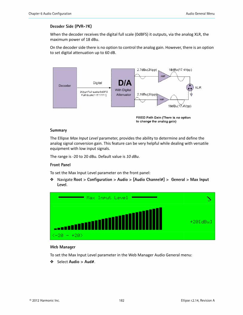
Chapter 6 Audio Configuration Audio General Menu
© 2012 Harmonic Inc. 182 Ellipse r.2.14, Revision A
Decoder Side (PVR-7K)
When the decoder receives the digital full scale (0dBFS) it outputs, via the analog XLR, the maximum power of 18 dBu.
On the decoder side there is no option to control the analog gain. However, there is an option to set digital attenuation up to 60 dB.
Summary
The Ellipse Max Input Level parameter, provides the ability to determine and define the analog signal conversion gain. This feature can be very helpful while dealing with versatile equipment with low input signals.
The range is -20 to 20 dBu. Default value is 10 dBu.
Front Panel
To set the Max Input Level parameter on the front panel: Navigate Root > Configuration > Audio > [Audio Channel#] > General > Max Input
Level.
Web Manager
To set the Max Input Level parameter in the Web Manager Audio General menu: Select Audio > Aud#.
Max Input Level
+20[dBu]
<-20 - +20>
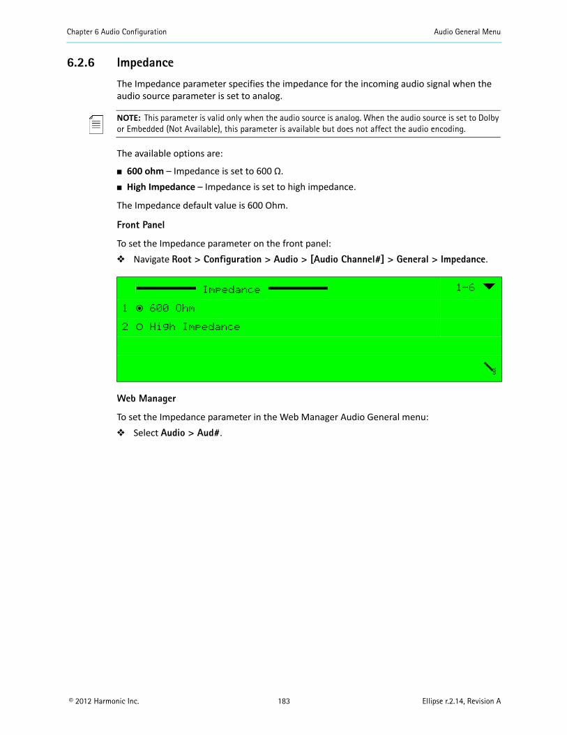
Chapter 6 Audio Configuration Audio General Menu
© 2012 Harmonic Inc. 183 Ellipse r.2.14, Revision A
6.2.6 Impedance
The Impedance parameter specifies the impedance for the incoming audio signal when the audio source parameter is set to analog.
NOTE: This parameter is valid only when the audio source is analog. When the audio source is set to Dolby or Embedded (Not Available), this parameter is available but does not affect the audio encoding.
The available options are:
600 ohm – Impedance is set to 600 Ω. High Impedance – Impedance is set to high impedance.
The Impedance default value is 600 Ohm.
Front Panel
To set the Impedance parameter on the front panel: Navigate Root > Configuration > Audio > [Audio Channel#] > General > Impedance.
Web Manager
To set the Impedance parameter in the Web Manager Audio General menu: Select Audio > Aud#.
Impedance 1-6
1 ƒ 600 Ohm
2 ‚ High Impedance
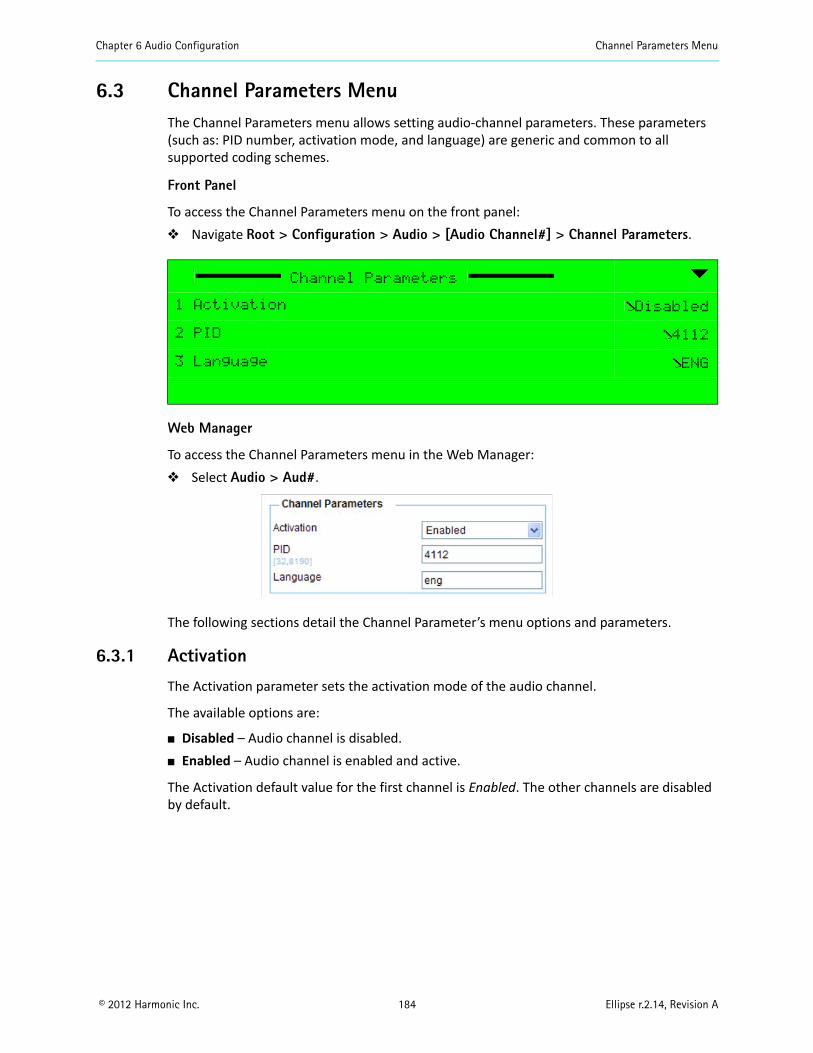
Chapter 6 Audio Configuration Channel Parameters Menu
© 2012 Harmonic Inc. 184 Ellipse r.2.14, Revision A
6.3 Channel Parameters MenuThe Channel Parameters menu allows setting audio-channel parameters. These parameters (such as: PID number, activation mode, and language) are generic and common to all supported coding schemes.
Front Panel
To access the Channel Parameters menu on the front panel: Navigate Root > Configuration > Audio > [Audio Channel#] > Channel Parameters.
Web Manager
To access the Channel Parameters menu in the Web Manager: Select Audio > Aud#.
The following sections detail the Channel Parameter’s menu options and parameters.
6.3.1 Activation
The Activation parameter sets the activation mode of the audio channel.
The available options are:
Disabled – Audio channel is disabled. Enabled – Audio channel is enabled and active.
The Activation default value for the first channel is Enabled. The other channels are disabled by default.
Channel Parameters
1 Activation Disabled
2 PID 4112
3 Language ENG
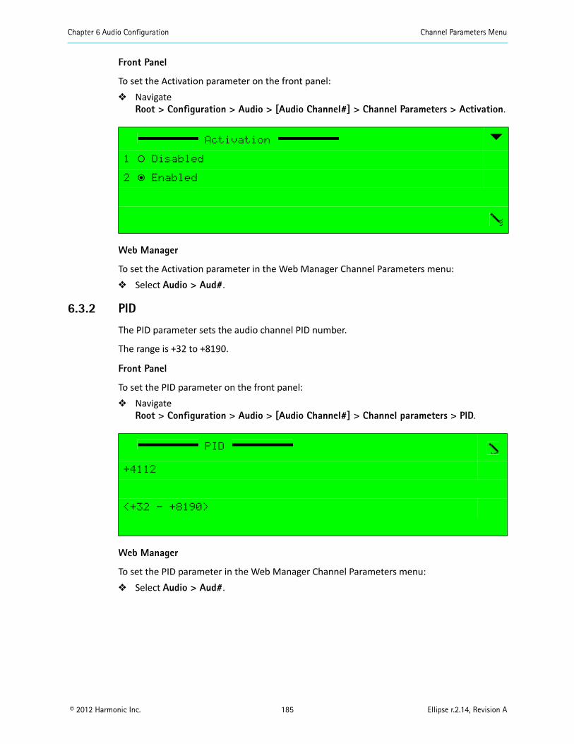
Chapter 6 Audio Configuration Channel Parameters Menu
© 2012 Harmonic Inc. 185 Ellipse r.2.14, Revision A
Front Panel
To set the Activation parameter on the front panel: Navigate
Root > Configuration > Audio > [Audio Channel#] > Channel Parameters > Activation.
Web Manager
To set the Activation parameter in the Web Manager Channel Parameters menu: Select Audio > Aud#.
6.3.2 PID
The PID parameter sets the audio channel PID number.
The range is +32 to +8190.
Front Panel
To set the PID parameter on the front panel: Navigate
Root > Configuration > Audio > [Audio Channel#] > Channel parameters > PID.
Web Manager
To set the PID parameter in the Web Manager Channel Parameters menu: Select Audio > Aud#.
Activation
1 ‚ Disabled
2 ƒ Enabled
PID
+4112
<+32 - +8190>
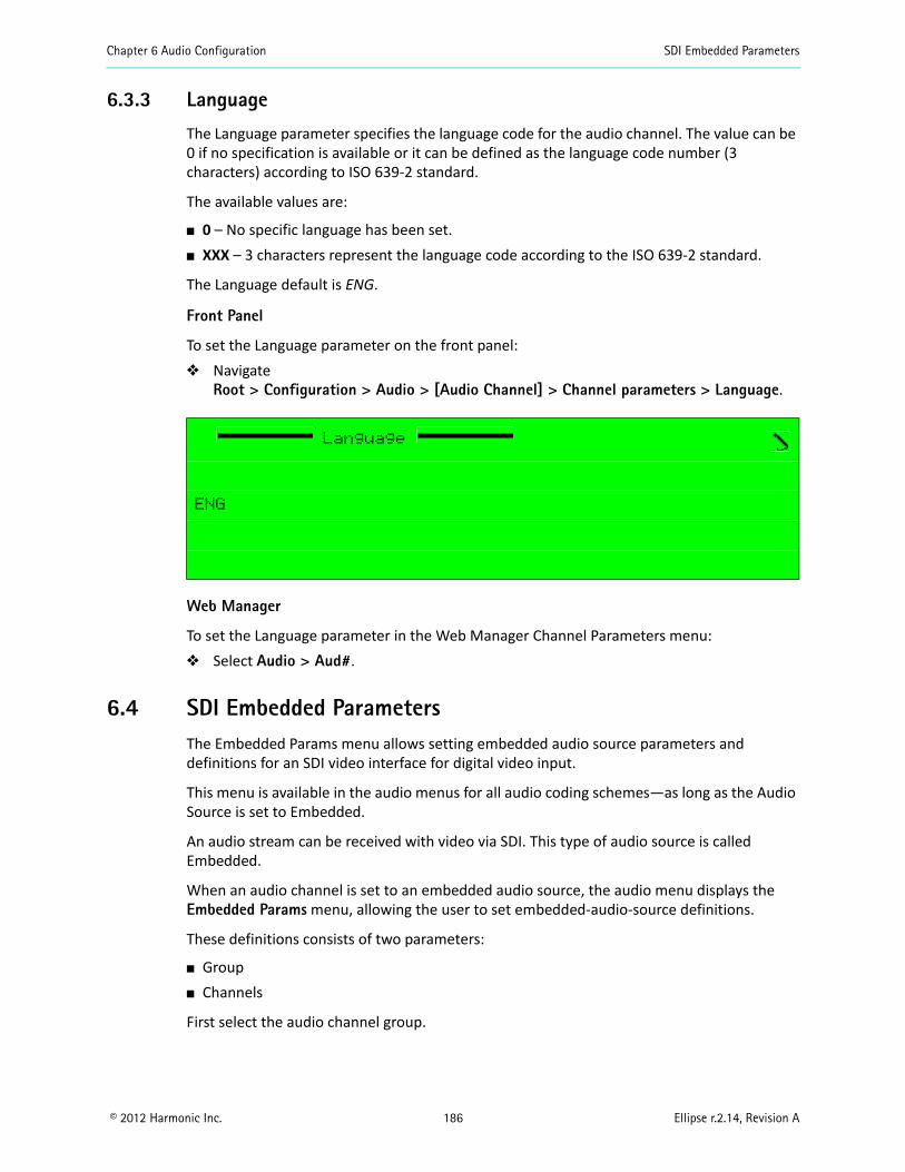
Chapter 6 Audio Configuration SDI Embedded Parameters
© 2012 Harmonic Inc. 186 Ellipse r.2.14, Revision A
6.3.3 Language
The Language parameter specifies the language code for the audio channel. The value can be 0 if no specification is available or it can be defined as the language code number (3 characters) according to ISO 639-2 standard.
The available values are:
0 – No specific language has been set. XXX – 3 characters represent the language code according to the ISO 639-2 standard.
The Language default is ENG.
Front Panel
To set the Language parameter on the front panel: Navigate
Root > Configuration > Audio > [Audio Channel] > Channel parameters > Language.
Web Manager
To set the Language parameter in the Web Manager Channel Parameters menu: Select Audio > Aud#.
6.4 SDI Embedded ParametersThe Embedded Params menu allows setting embedded audio source parameters and definitions for an SDI video interface for digital video input.
This menu is available in the audio menus for all audio coding schemes—as long as the Audio Source is set to Embedded.
An audio stream can be received with video via SDI. This type of audio source is called Embedded.
When an audio channel is set to an embedded audio source, the audio menu displays the Embedded Params menu, allowing the user to set embedded-audio-source definitions.
These definitions consists of two parameters:
Group Channels
First select the audio channel group.
Language
ENG
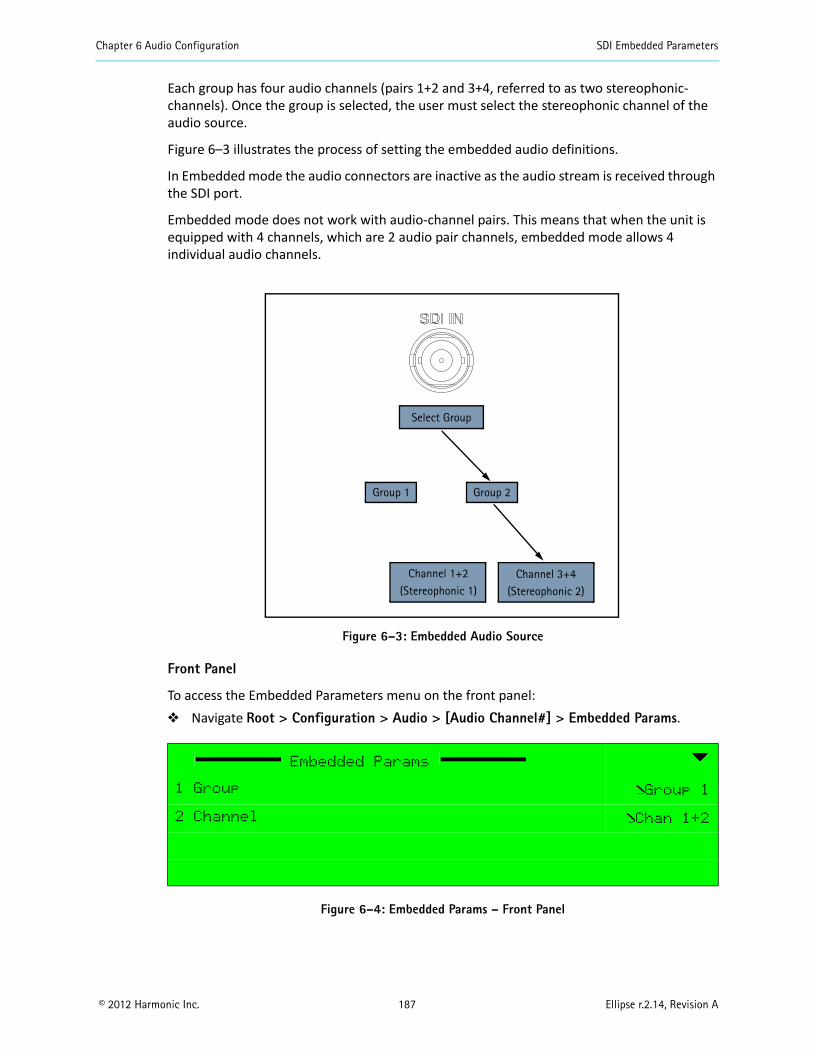
Chapter 6 Audio Configuration SDI Embedded Parameters
© 2012 Harmonic Inc. 187 Ellipse r.2.14, Revision A
Each group has four audio channels (pairs 1+2 and 3+4, referred to as two stereophonic-channels). Once the group is selected, the user must select the stereophonic channel of the audio source.
Figure 6–3 illustrates the process of setting the embedded audio definitions.
In Embedded mode the audio connectors are inactive as the audio stream is received through the SDI port.
Embedded mode does not work with audio-channel pairs. This means that when the unit is equipped with 4 channels, which are 2 audio pair channels, embedded mode allows 4 individual audio channels.
Figure 6–3: Embedded Audio Source
Front Panel
To access the Embedded Parameters menu on the front panel: Navigate Root > Configuration > Audio > [Audio Channel#] > Embedded Params.
Figure 6–4: Embedded Params – Front Panel
Embedded Params
1 Group Group 1
2 Channel Chan 1+2
Select Group
Group 1 Group 2
Channel 1+2(Stereophonic 1)
Channel 3+4(Stereophonic 2)
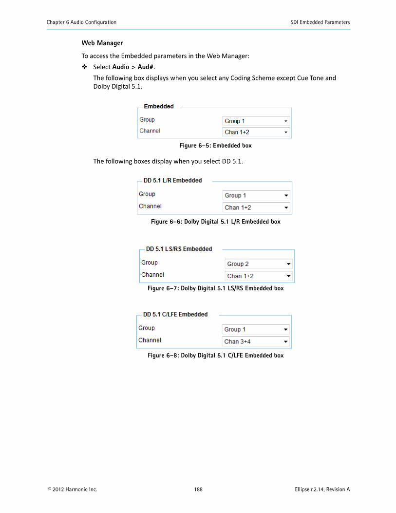
Chapter 6 Audio Configuration SDI Embedded Parameters
© 2012 Harmonic Inc. 188 Ellipse r.2.14, Revision A
Web Manager
To access the Embedded parameters in the Web Manager: Select Audio > Aud#.
The following box displays when you select any Coding Scheme except Cue Tone and Dolby Digital 5.1.
Figure 6–5: Embedded box
The following boxes display when you select DD 5.1.
Figure 6–6: Dolby Digital 5.1 L/R Embedded box
Figure 6–7: Dolby Digital 5.1 LS/RS Embedded box
Figure 6–8: Dolby Digital 5.1 C/LFE Embedded box
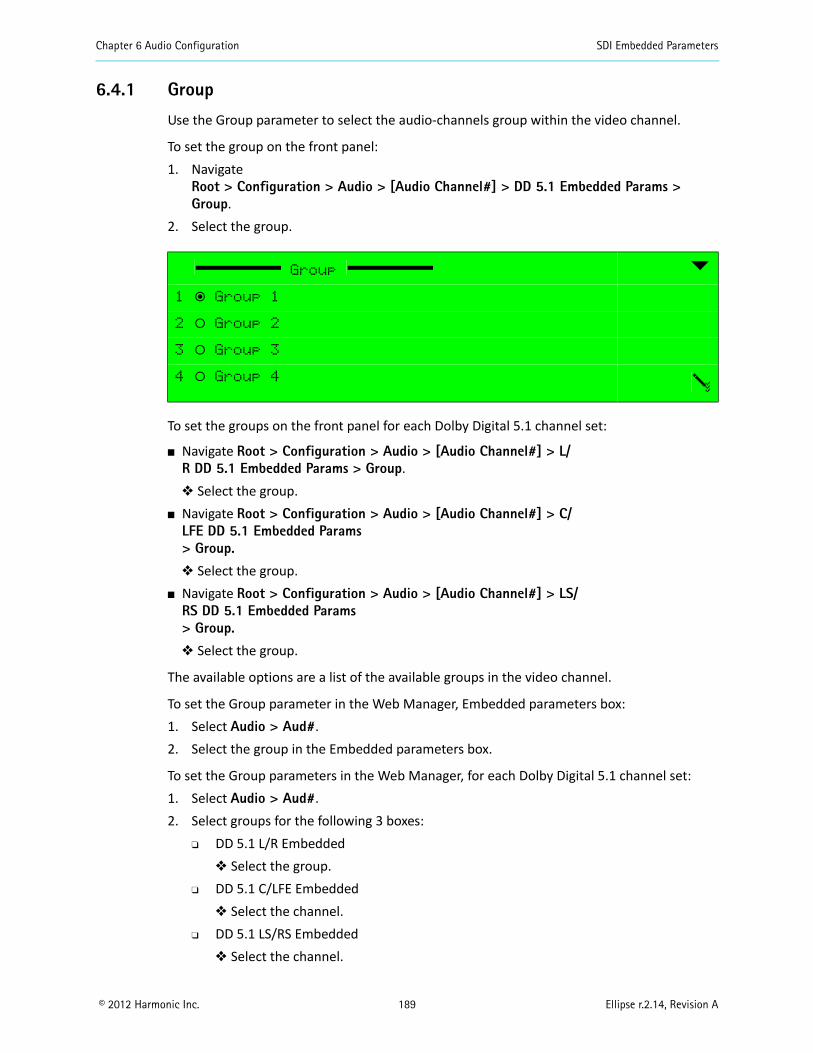
Chapter 6 Audio Configuration SDI Embedded Parameters
© 2012 Harmonic Inc. 189 Ellipse r.2.14, Revision A
6.4.1 Group
Use the Group parameter to select the audio-channels group within the video channel.
To set the group on the front panel:1. Navigate
Root > Configuration > Audio > [Audio Channel#] > DD 5.1 Embedded Params > Group.
2. Select the group.
To set the groups on the front panel for each Dolby Digital 5.1 channel set:
Navigate Root > Configuration > Audio > [Audio Channel#] > L/R DD 5.1 Embedded Params > Group. Select the group.
Navigate Root > Configuration > Audio > [Audio Channel#] > C/LFE DD 5.1 Embedded Params> Group. Select the group.
Navigate Root > Configuration > Audio > [Audio Channel#] > LS/RS DD 5.1 Embedded Params> Group. Select the group.
The available options are a list of the available groups in the video channel.
To set the Group parameter in the Web Manager, Embedded parameters box:1. Select Audio > Aud#.2. Select the group in the Embedded parameters box.
To set the Group parameters in the Web Manager, for each Dolby Digital 5.1 channel set:1. Select Audio > Aud#.2. Select groups for the following 3 boxes:
DD 5.1 L/R Embedded Select the group.
DD 5.1 C/LFE Embedded Select the channel.
DD 5.1 LS/RS Embedded Select the channel.
Group
1 ƒ Group 1
2 ‚ Group 2
3 ‚ Group 3
4 ‚ Group 4
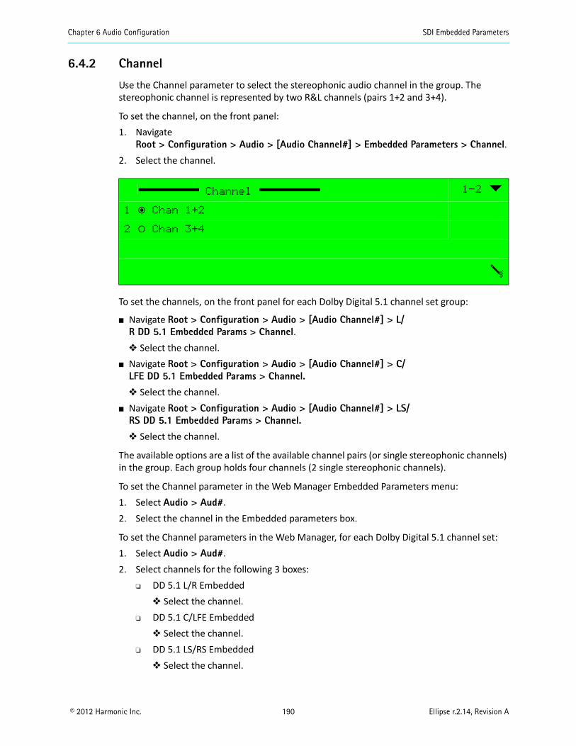
Chapter 6 Audio Configuration SDI Embedded Parameters
© 2012 Harmonic Inc. 190 Ellipse r.2.14, Revision A
6.4.2 Channel
Use the Channel parameter to select the stereophonic audio channel in the group. The stereophonic channel is represented by two R&L channels (pairs 1+2 and 3+4).
To set the channel, on the front panel:1. Navigate
Root > Configuration > Audio > [Audio Channel#] > Embedded Parameters > Channel.2. Select the channel.
To set the channels, on the front panel for each Dolby Digital 5.1 channel set group:
Navigate Root > Configuration > Audio > [Audio Channel#] > L/R DD 5.1 Embedded Params > Channel. Select the channel.
Navigate Root > Configuration > Audio > [Audio Channel#] > C/LFE DD 5.1 Embedded Params > Channel. Select the channel.
Navigate Root > Configuration > Audio > [Audio Channel#] > LS/RS DD 5.1 Embedded Params > Channel. Select the channel.
The available options are a list of the available channel pairs (or single stereophonic channels) in the group. Each group holds four channels (2 single stereophonic channels).
To set the Channel parameter in the Web Manager Embedded Parameters menu:1. Select Audio > Aud#.2. Select the channel in the Embedded parameters box.
To set the Channel parameters in the Web Manager, for each Dolby Digital 5.1 channel set:1. Select Audio > Aud#.2. Select channels for the following 3 boxes:
DD 5.1 L/R Embedded Select the channel.
DD 5.1 C/LFE Embedded Select the channel.
DD 5.1 LS/RS Embedded Select the channel.
Channel 1-2
1 ƒ Chan 1+2
2 ‚ Chan 3+4
Chapter 6 Audio Configuration Coding Scheme Configuration
© 2012 Harmonic Inc. 191 Ellipse r.2.14, Revision A
6.5 Coding Scheme ConfigurationThe Ellipse supports a wide range of audio coding schemes, allowing the user a variety of audio-encoding options. Each audio channel, in addition to the common General and Channel Parameter’s menus, also holds one or two specific-configuration menus. These menus are dynamic and displayed according to the selected coding-scheme of the audio channel.
The available coding scheme configuration menus are:
MPEG-1 Layer 2 Parameters Dolby Digital 2.0 Parameters Dolby Digital 2.0 and Dolby Digital 5.1 Pre-Processing MPEG-2 AAC LC Parameters MPEG-4 HE AAC Parameters Dolby Digital 5.1
The encoder supports three pass through schemes: Dolby Digital Pass Through Parameters Dolby E Pass Through Parameters Menu Linear PCM Pass Through Parameters Menu
NOTE: Pass through audio streams must be synchronized according to an external clock. Refer to Appendix D, Audio Pass Through Schemes Set-Up, for a detailed description how to use the external clock.
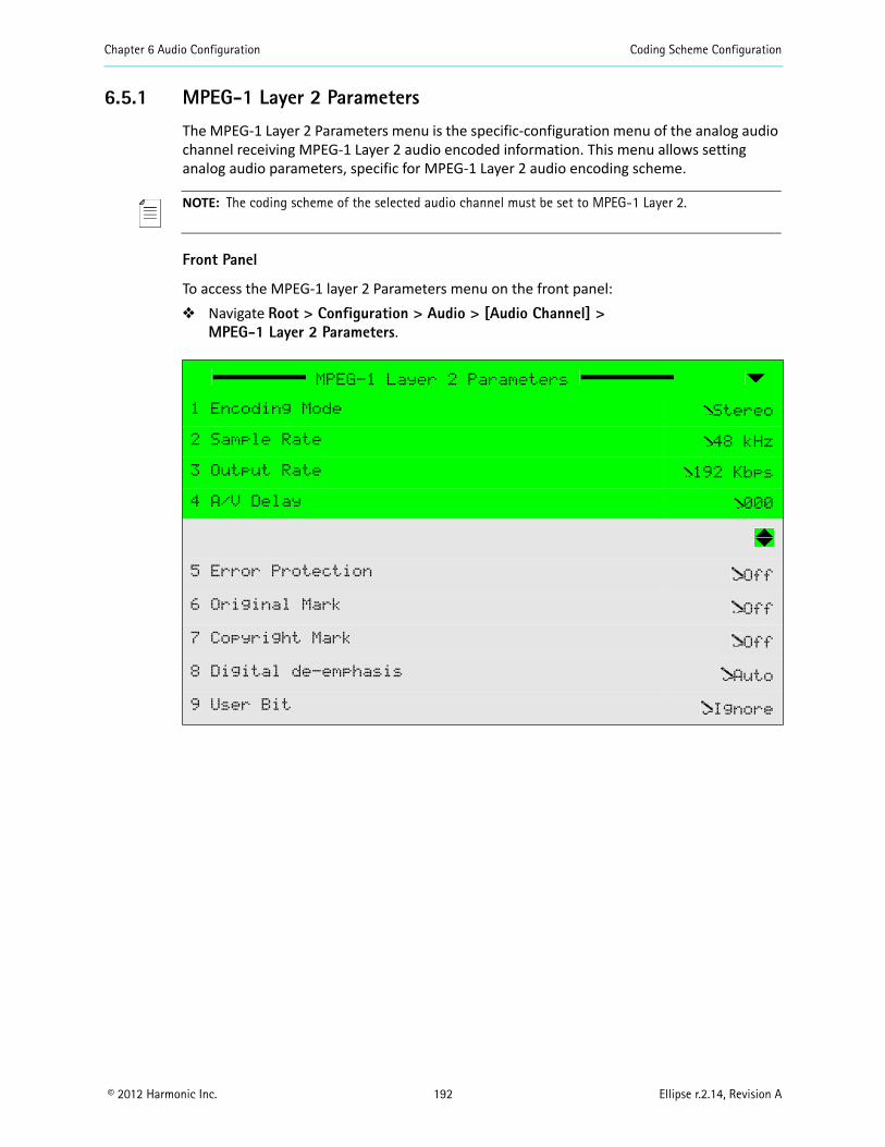
Chapter 6 Audio Configuration Coding Scheme Configuration
© 2012 Harmonic Inc. 192 Ellipse r.2.14, Revision A
6.5.1 MPEG-1 Layer 2 Parameters
The MPEG-1 Layer 2 Parameters menu is the specific-configuration menu of the analog audio channel receiving MPEG-1 Layer 2 audio encoded information. This menu allows setting analog audio parameters, specific for MPEG-1 Layer 2 audio encoding scheme.
NOTE: The coding scheme of the selected audio channel must be set to MPEG-1 Layer 2.
Front Panel
To access the MPEG-1 layer 2 Parameters menu on the front panel: Navigate Root > Configuration > Audio > [Audio Channel] >
MPEG-1 Layer 2 Parameters.
MPEG-1 Layer 2 Parameters
1 Encoding Mode Stereo
2 Sample Rate 48 kHz
3 Output Rate 192 Kbps
4 A/V Delay 000
5 Error Protection Off
6 Original Mark Off
7 Copyright Mark Off
8 Digital de-emphasis Auto
9 User Bit Ignore
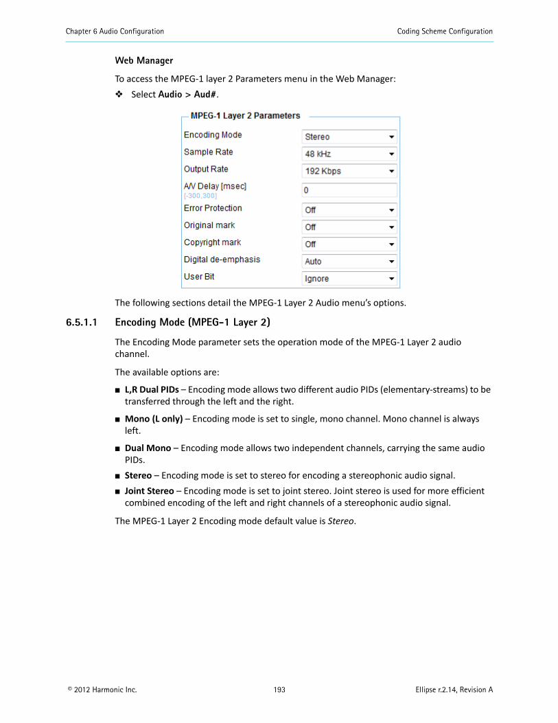
Chapter 6 Audio Configuration Coding Scheme Configuration
© 2012 Harmonic Inc. 193 Ellipse r.2.14, Revision A
Web Manager
To access the MPEG-1 layer 2 Parameters menu in the Web Manager: Select Audio > Aud#.
The following sections detail the MPEG-1 Layer 2 Audio menu’s options.
6.5.1.1 Encoding Mode (MPEG-1 Layer 2)
The Encoding Mode parameter sets the operation mode of the MPEG-1 Layer 2 audio channel.
The available options are:
L,R Dual PIDs – Encoding mode allows two different audio PIDs (elementary-streams) to be transferred through the left and the right.
Mono (L only) – Encoding mode is set to single, mono channel. Mono channel is always left.
Dual Mono – Encoding mode allows two independent channels, carrying the same audio PIDs.
Stereo – Encoding mode is set to stereo for encoding a stereophonic audio signal. Joint Stereo – Encoding mode is set to joint stereo. Joint stereo is used for more efficient
combined encoding of the left and right channels of a stereophonic audio signal.
The MPEG-1 Layer 2 Encoding mode default value is Stereo.
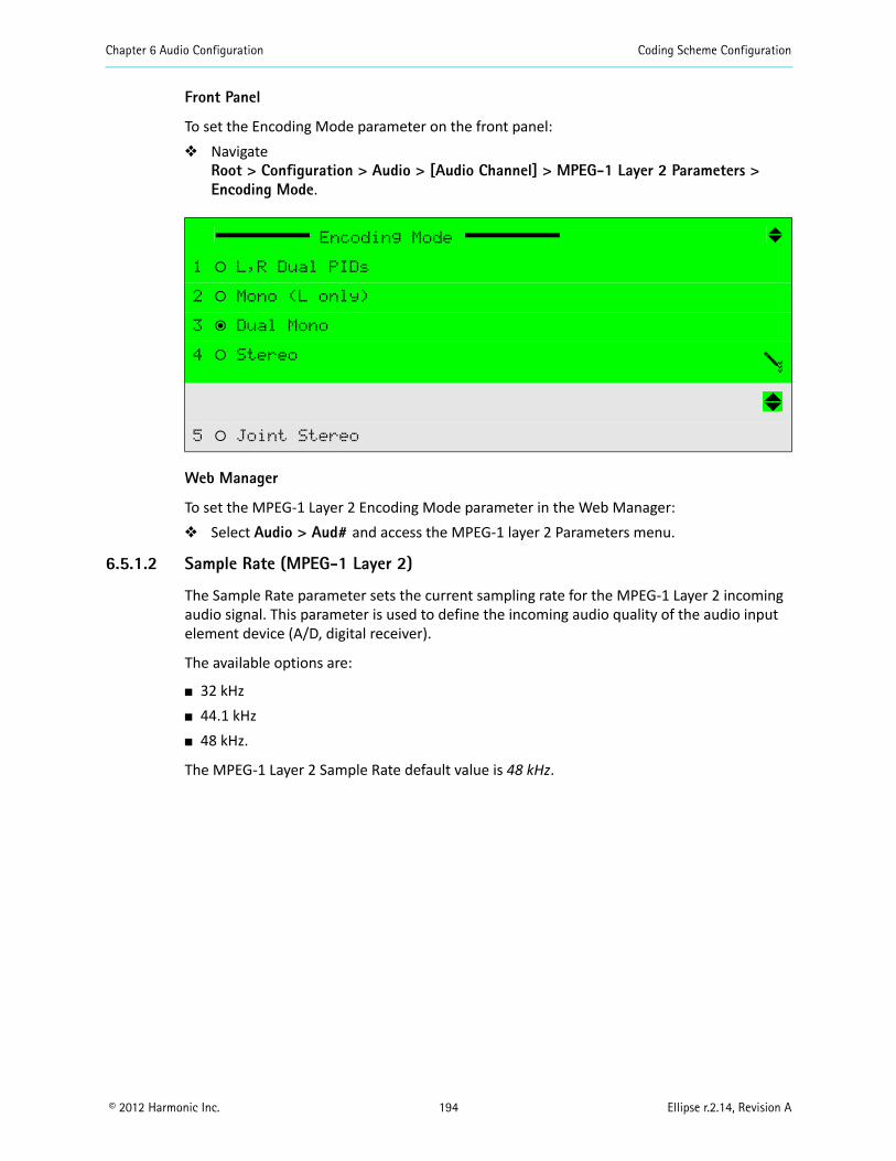
Chapter 6 Audio Configuration Coding Scheme Configuration
© 2012 Harmonic Inc. 194 Ellipse r.2.14, Revision A
Front Panel
To set the Encoding Mode parameter on the front panel: Navigate
Root > Configuration > Audio > [Audio Channel] > MPEG-1 Layer 2 Parameters > Encoding Mode.
Web Manager
To set the MPEG-1 Layer 2 Encoding Mode parameter in the Web Manager: Select Audio > Aud# and access the MPEG-1 layer 2 Parameters menu.
6.5.1.2 Sample Rate (MPEG-1 Layer 2)
The Sample Rate parameter sets the current sampling rate for the MPEG-1 Layer 2 incoming audio signal. This parameter is used to define the incoming audio quality of the audio input element device (A/D, digital receiver).
The available options are:
32 kHz 44.1 kHz 48 kHz.
The MPEG-1 Layer 2 Sample Rate default value is 48 kHz.
Encoding Mode
1 ‚ L,R Dual PIDs
2 ‚ Mono (L only)
3 ƒ Dual Mono
4 ‚ Stereo
5 ‚ Joint Stereo
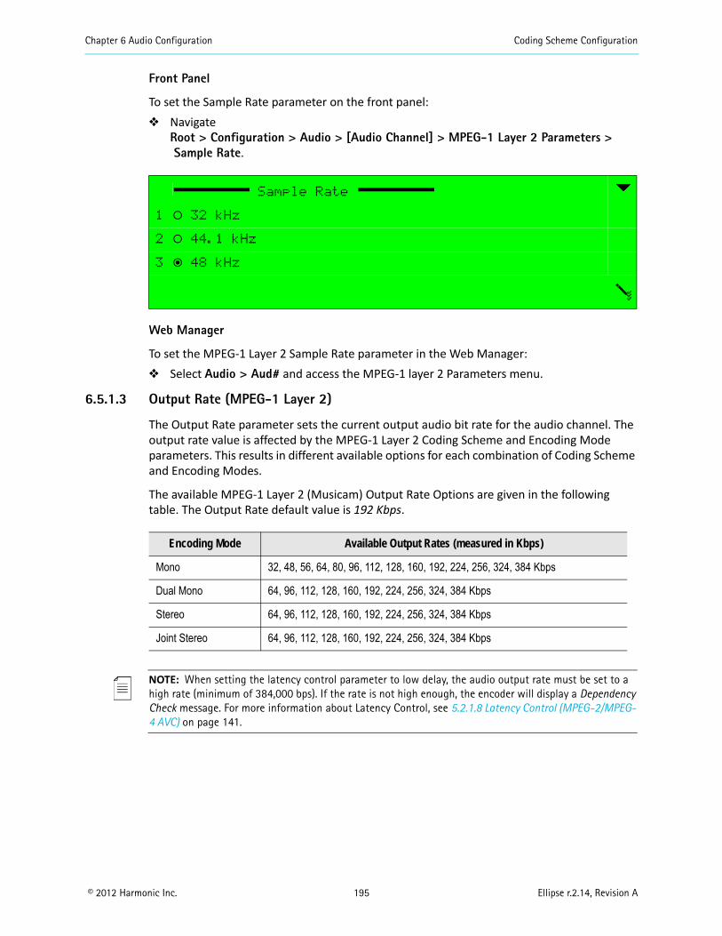
Chapter 6 Audio Configuration Coding Scheme Configuration
© 2012 Harmonic Inc. 195 Ellipse r.2.14, Revision A
Front Panel
To set the Sample Rate parameter on the front panel: Navigate
Root > Configuration > Audio > [Audio Channel] > MPEG-1 Layer 2 Parameters >Sample Rate.
Web Manager
To set the MPEG-1 Layer 2 Sample Rate parameter in the Web Manager: Select Audio > Aud# and access the MPEG-1 layer 2 Parameters menu.
6.5.1.3 Output Rate (MPEG-1 Layer 2)
The Output Rate parameter sets the current output audio bit rate for the audio channel. The output rate value is affected by the MPEG-1 Layer 2 Coding Scheme and Encoding Mode parameters. This results in different available options for each combination of Coding Scheme and Encoding Modes.
The available MPEG-1 Layer 2 (Musicam) Output Rate Options are given in the following table. The Output Rate default value is 192 Kbps.
NOTE: When setting the latency control parameter to low delay, the audio output rate must be set to a high rate (minimum of 384,000 bps). If the rate is not high enough, the encoder will display a Dependency Check message. For more information about Latency Control, see 5.2.1.8 Latency Control (MPEG-2/MPEG-4 AVC) on page 141.
Sample Rate
1 ‚ 32 kHz
2 ‚ 44.1 kHz
3 ƒ 48 kHz
Encoding Mode Available Output Rates (measured in Kbps)
Mono 32, 48, 56, 64, 80, 96, 112, 128, 160, 192, 224, 256, 324, 384 Kbps
Dual Mono 64, 96, 112, 128, 160, 192, 224, 256, 324, 384 Kbps
Stereo 64, 96, 112, 128, 160, 192, 224, 256, 324, 384 Kbps
Joint Stereo 64, 96, 112, 128, 160, 192, 224, 256, 324, 384 Kbps
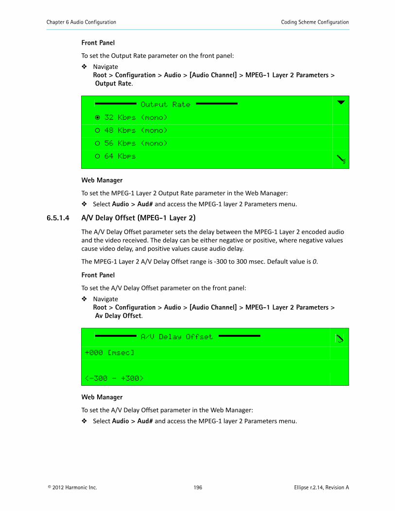
Chapter 6 Audio Configuration Coding Scheme Configuration
© 2012 Harmonic Inc. 196 Ellipse r.2.14, Revision A
Front Panel
To set the Output Rate parameter on the front panel: Navigate
Root > Configuration > Audio > [Audio Channel] > MPEG-1 Layer 2 Parameters >Output Rate.
Web Manager
To set the MPEG-1 Layer 2 Output Rate parameter in the Web Manager: Select Audio > Aud# and access the MPEG-1 layer 2 Parameters menu.
6.5.1.4 A/V Delay Offset (MPEG-1 Layer 2)
The A/V Delay Offset parameter sets the delay between the MPEG-1 Layer 2 encoded audio and the video received. The delay can be either negative or positive, where negative values cause video delay, and positive values cause audio delay.
The MPEG-1 Layer 2 A/V Delay Offset range is -300 to 300 msec. Default value is 0.
Front Panel
To set the A/V Delay Offset parameter on the front panel: Navigate
Root > Configuration > Audio > [Audio Channel] > MPEG-1 Layer 2 Parameters >Av Delay Offset.
Web Manager
To set the A/V Delay Offset parameter in the Web Manager: Select Audio > Aud# and access the MPEG-1 layer 2 Parameters menu.
Output Rate
ƒ 32 Kbps (mono)
‚ 48 Kbps (mono)
‚ 56 Kbps (mono)
‚ 64 Kbps
A/V Delay Offset
+000 [msec]
<-300 - +300>
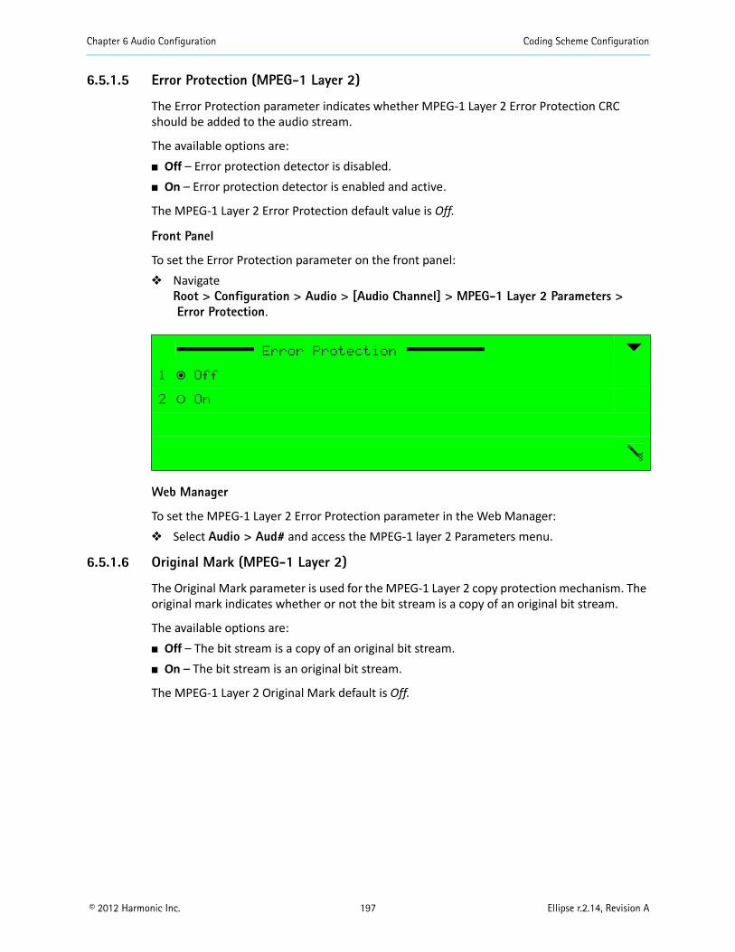
Chapter 6 Audio Configuration Coding Scheme Configuration
© 2012 Harmonic Inc. 197 Ellipse r.2.14, Revision A
6.5.1.5 Error Protection (MPEG-1 Layer 2)
The Error Protection parameter indicates whether MPEG-1 Layer 2 Error Protection CRC should be added to the audio stream.
The available options are: Off – Error protection detector is disabled. On – Error protection detector is enabled and active.
The MPEG-1 Layer 2 Error Protection default value is Off.
Front Panel
To set the Error Protection parameter on the front panel: Navigate
Root > Configuration > Audio > [Audio Channel] > MPEG-1 Layer 2 Parameters >Error Protection.
Web Manager
To set the MPEG-1 Layer 2 Error Protection parameter in the Web Manager: Select Audio > Aud# and access the MPEG-1 layer 2 Parameters menu.
6.5.1.6 Original Mark (MPEG-1 Layer 2)
The Original Mark parameter is used for the MPEG-1 Layer 2 copy protection mechanism. The original mark indicates whether or not the bit stream is a copy of an original bit stream.
The available options are: Off – The bit stream is a copy of an original bit stream. On – The bit stream is an original bit stream.
The MPEG-1 Layer 2 Original Mark default is Off.
Error Protection
1 ƒ Off
2 ‚ On
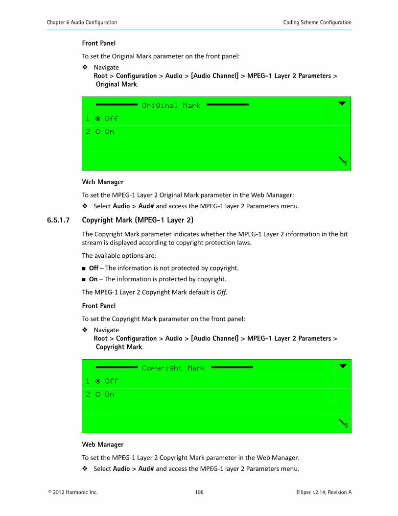
Chapter 6 Audio Configuration Coding Scheme Configuration
© 2012 Harmonic Inc. 198 Ellipse r.2.14, Revision A
Front Panel
To set the Original Mark parameter on the front panel: Navigate
Root > Configuration > Audio > [Audio Channel] > MPEG-1 Layer 2 Parameters >Original Mark.
Web Manager
To set the MPEG-1 Layer 2 Original Mark parameter in the Web Manager: Select Audio > Aud# and access the MPEG-1 layer 2 Parameters menu.
6.5.1.7 Copyright Mark (MPEG-1 Layer 2)
The Copyright Mark parameter indicates whether the MPEG-1 Layer 2 information in the bit stream is displayed according to copyright protection laws.
The available options are:
Off – The information is not protected by copyright. On – The information is protected by copyright.
The MPEG-1 Layer 2 Copyright Mark default is Off.
Front Panel
To set the Copyright Mark parameter on the front panel: Navigate
Root > Configuration > Audio > [Audio Channel] > MPEG-1 Layer 2 Parameters >Copyright Mark.
Web Manager
To set the MPEG-1 Layer 2 Copyright Mark parameter in the Web Manager: Select Audio > Aud# and access the MPEG-1 layer 2 Parameters menu.
Original Mark
1 ƒ Off
2 ‚ On
Copyright Mark
1 ƒ Off
2 ‚ On
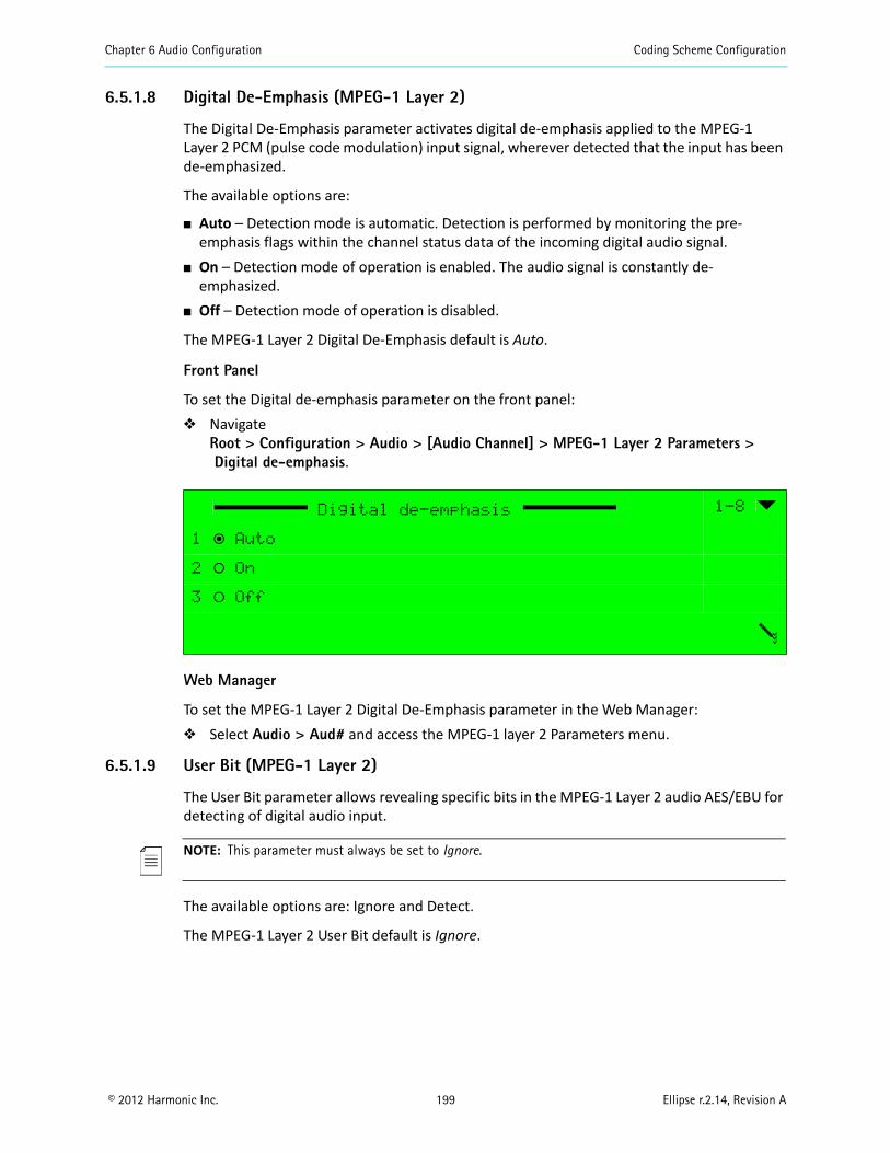
Chapter 6 Audio Configuration Coding Scheme Configuration
© 2012 Harmonic Inc. 199 Ellipse r.2.14, Revision A
6.5.1.8 Digital De-Emphasis (MPEG-1 Layer 2)
The Digital De-Emphasis parameter activates digital de-emphasis applied to the MPEG-1 Layer 2 PCM (pulse code modulation) input signal, wherever detected that the input has been de-emphasized.
The available options are:
Auto – Detection mode is automatic. Detection is performed by monitoring the pre-emphasis flags within the channel status data of the incoming digital audio signal.
On – Detection mode of operation is enabled. The audio signal is constantly de-emphasized.
Off – Detection mode of operation is disabled.
The MPEG-1 Layer 2 Digital De-Emphasis default is Auto.
Front Panel
To set the Digital de-emphasis parameter on the front panel: Navigate
Root > Configuration > Audio > [Audio Channel] > MPEG-1 Layer 2 Parameters >Digital de-emphasis.
Web Manager
To set the MPEG-1 Layer 2 Digital De-Emphasis parameter in the Web Manager: Select Audio > Aud# and access the MPEG-1 layer 2 Parameters menu.
6.5.1.9 User Bit (MPEG-1 Layer 2)
The User Bit parameter allows revealing specific bits in the MPEG-1 Layer 2 audio AES/EBU for detecting of digital audio input.
NOTE: This parameter must always be set to Ignore.
The available options are: Ignore and Detect.
The MPEG-1 Layer 2 User Bit default is Ignore.
Digital de-emphasis 1-8
1 ƒ Auto
2 ‚ On
3 ‚ Off
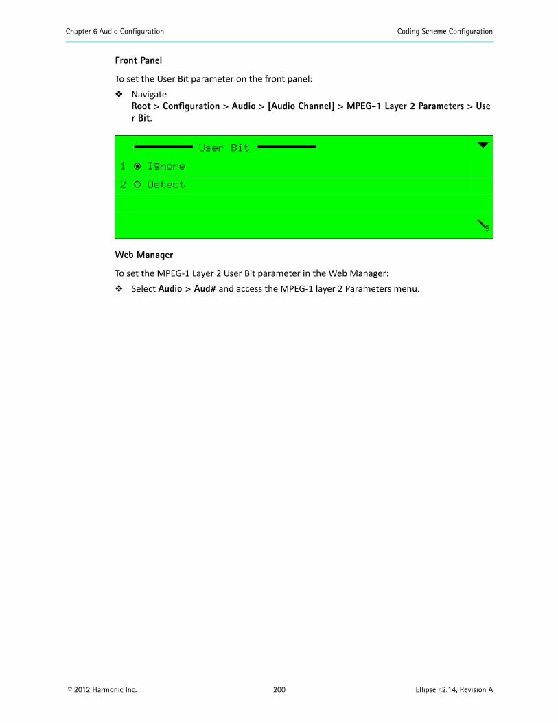
Chapter 6 Audio Configuration Coding Scheme Configuration
© 2012 Harmonic Inc. 200 Ellipse r.2.14, Revision A
Front Panel
To set the User Bit parameter on the front panel: Navigate
Root > Configuration > Audio > [Audio Channel] > MPEG-1 Layer 2 Parameters > User Bit.
Web Manager
To set the MPEG-1 Layer 2 User Bit parameter in the Web Manager: Select Audio > Aud# and access the MPEG-1 layer 2 Parameters menu.
User Bit
1 ƒ Ignore
2 ‚ Detect
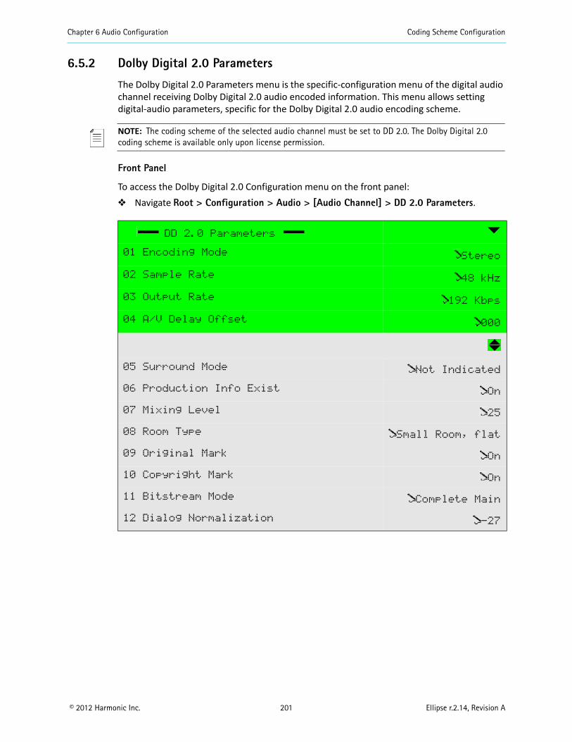
Chapter 6 Audio Configuration Coding Scheme Configuration
© 2012 Harmonic Inc. 201 Ellipse r.2.14, Revision A
6.5.2 Dolby Digital 2.0 Parameters
The Dolby Digital 2.0 Parameters menu is the specific-configuration menu of the digital audio channel receiving Dolby Digital 2.0 audio encoded information. This menu allows setting digital-audio parameters, specific for the Dolby Digital 2.0 audio encoding scheme.
NOTE: The coding scheme of the selected audio channel must be set to DD 2.0. The Dolby Digital 2.0 coding scheme is available only upon license permission.
Front Panel
To access the Dolby Digital 2.0 Configuration menu on the front panel: Navigate Root > Configuration > Audio > [Audio Channel] > DD 2.0 Parameters.
DD 2.0 Parameters
01 Encoding Mode Stereo
02 Sample Rate 48 kHz
03 Output Rate 192 Kbps
04 A/V Delay Offset 000
05 Surround Mode Not Indicated
06 Production Info Exist On
07 Mixing Level 25
08 Room Type Small Room, flat
09 Original Mark On
10 Copyright Mark On
11 Bitstream Mode Complete Main
12 Dialog Normalization -27
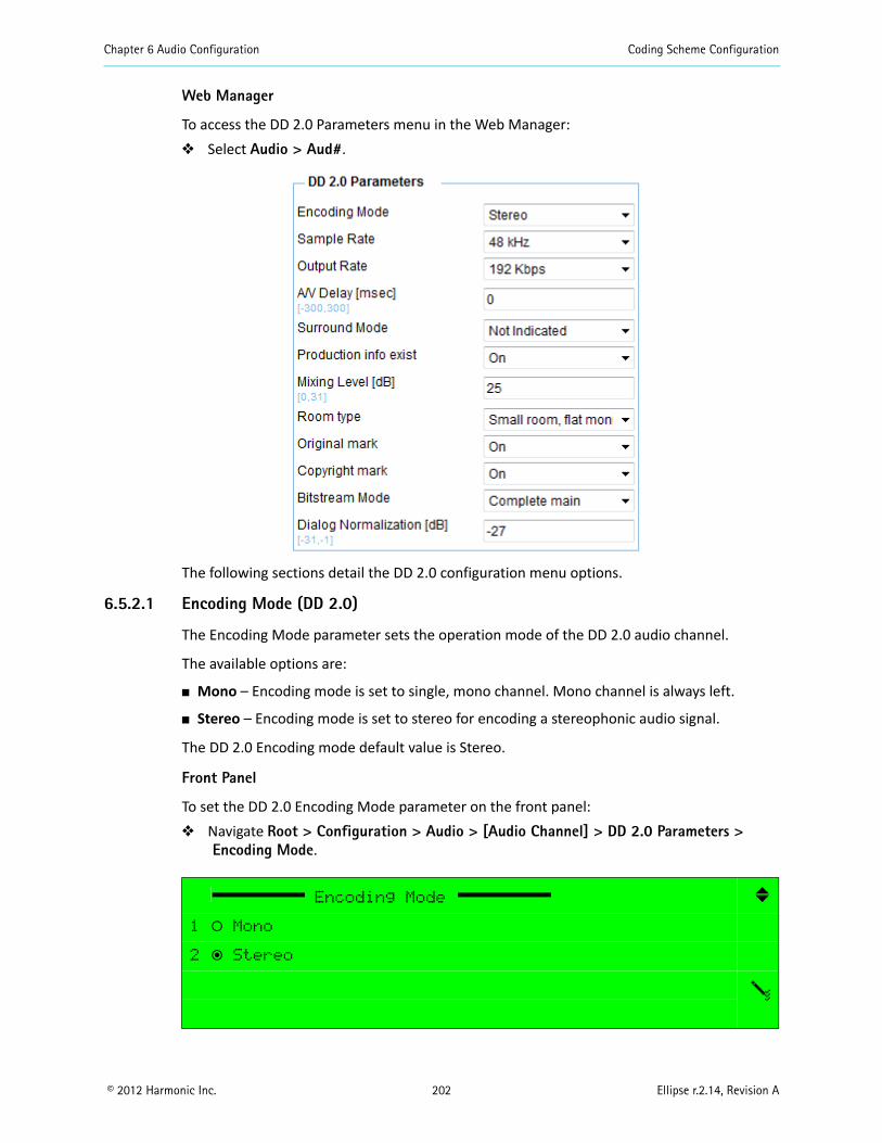
Chapter 6 Audio Configuration Coding Scheme Configuration
© 2012 Harmonic Inc. 202 Ellipse r.2.14, Revision A
Web Manager
To access the DD 2.0 Parameters menu in the Web Manager: Select Audio > Aud#.
The following sections detail the DD 2.0 configuration menu options.
6.5.2.1 Encoding Mode (DD 2.0)
The Encoding Mode parameter sets the operation mode of the DD 2.0 audio channel.
The available options are:
Mono – Encoding mode is set to single, mono channel. Mono channel is always left.
Stereo – Encoding mode is set to stereo for encoding a stereophonic audio signal.
The DD 2.0 Encoding mode default value is Stereo.
Front Panel
To set the DD 2.0 Encoding Mode parameter on the front panel: Navigate Root > Configuration > Audio > [Audio Channel] > DD 2.0 Parameters >
Encoding Mode.
Encoding Mode
1 ‚ Mono
2 ƒ Stereo
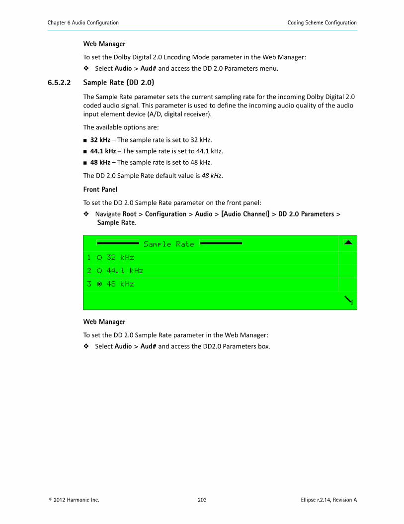
Chapter 6 Audio Configuration Coding Scheme Configuration
© 2012 Harmonic Inc. 203 Ellipse r.2.14, Revision A
Web Manager
To set the Dolby Digital 2.0 Encoding Mode parameter in the Web Manager: Select Audio > Aud# and access the DD 2.0 Parameters menu.
6.5.2.2 Sample Rate (DD 2.0)
The Sample Rate parameter sets the current sampling rate for the incoming Dolby Digital 2.0 coded audio signal. This parameter is used to define the incoming audio quality of the audio input element device (A/D, digital receiver).
The available options are:
32 kHz – The sample rate is set to 32 kHz. 44.1 kHz – The sample rate is set to 44.1 kHz. 48 kHz – The sample rate is set to 48 kHz.
The DD 2.0 Sample Rate default value is 48 kHz.
Front Panel
To set the DD 2.0 Sample Rate parameter on the front panel: Navigate Root > Configuration > Audio > [Audio Channel] > DD 2.0 Parameters >
Sample Rate.
Web Manager
To set the DD 2.0 Sample Rate parameter in the Web Manager: Select Audio > Aud# and access the DD2.0 Parameters box.
Sample Rate
1 ‚ 32 kHz
2 ‚ 44.1 kHz
3 ƒ 48 kHz
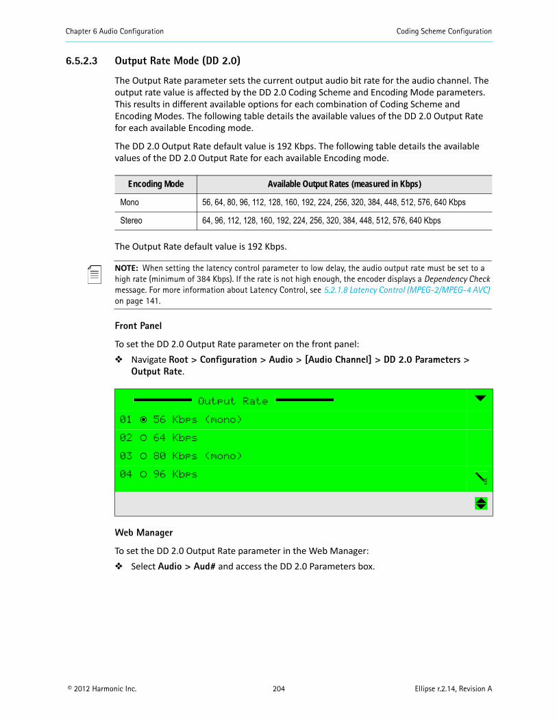
Chapter 6 Audio Configuration Coding Scheme Configuration
© 2012 Harmonic Inc. 204 Ellipse r.2.14, Revision A
6.5.2.3 Output Rate Mode (DD 2.0)
The Output Rate parameter sets the current output audio bit rate for the audio channel. The output rate value is affected by the DD 2.0 Coding Scheme and Encoding Mode parameters. This results in different available options for each combination of Coding Scheme and Encoding Modes. The following table details the available values of the DD 2.0 Output Rate for each available Encoding mode.
The DD 2.0 Output Rate default value is 192 Kbps. The following table details the available values of the DD 2.0 Output Rate for each available Encoding mode.
The Output Rate default value is 192 Kbps.
NOTE: When setting the latency control parameter to low delay, the audio output rate must be set to a high rate (minimum of 384 Kbps). If the rate is not high enough, the encoder displays a Dependency Check message. For more information about Latency Control, see 5.2.1.8 Latency Control (MPEG-2/MPEG-4 AVC) on page 141.
Front Panel
To set the DD 2.0 Output Rate parameter on the front panel: Navigate Root > Configuration > Audio > [Audio Channel] > DD 2.0 Parameters >
Output Rate.
Web Manager
To set the DD 2.0 Output Rate parameter in the Web Manager: Select Audio > Aud# and access the DD 2.0 Parameters box.
Encoding Mode Available Output Rates (measured in Kbps)
Mono 56, 64, 80, 96, 112, 128, 160, 192, 224, 256, 320, 384, 448, 512, 576, 640 Kbps
Stereo 64, 96, 112, 128, 160, 192, 224, 256, 320, 384, 448, 512, 576, 640 Kbps
Output Rate
01 ƒ 56 Kbps (mono)
02 ‚ 64 Kbps
03 ‚ 80 Kbps (mono)
04 ‚ 96 Kbps
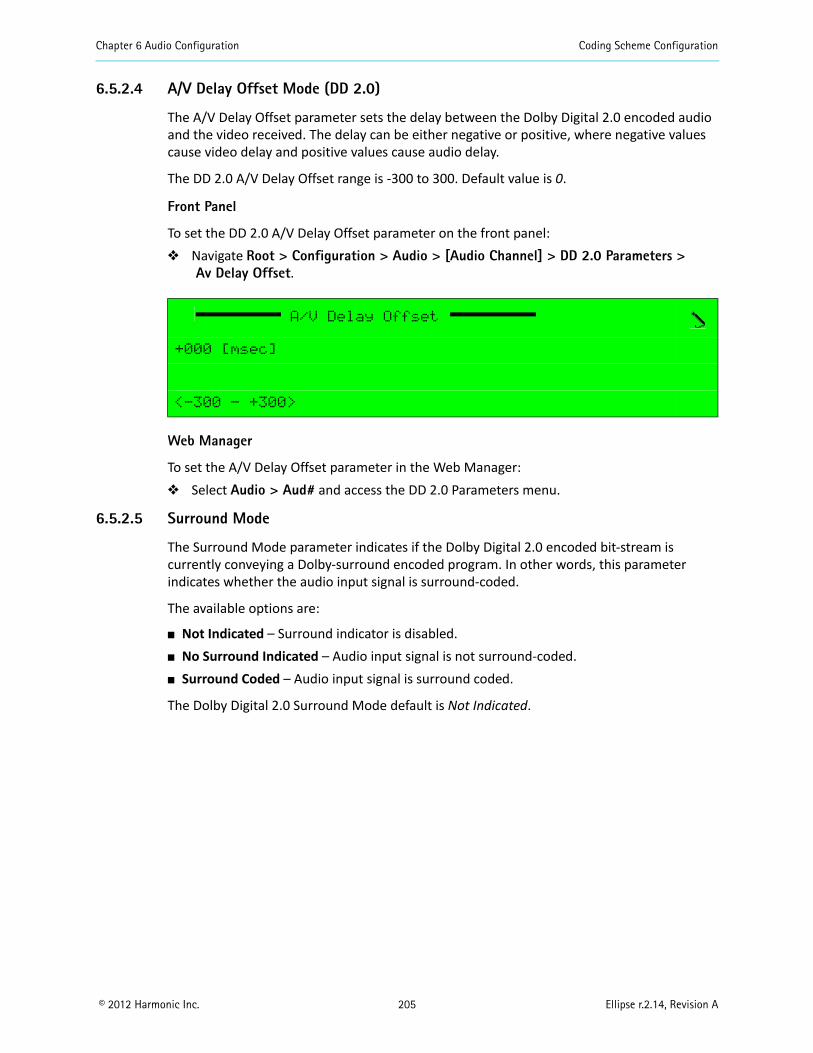
Chapter 6 Audio Configuration Coding Scheme Configuration
© 2012 Harmonic Inc. 205 Ellipse r.2.14, Revision A
6.5.2.4 A/V Delay Offset Mode (DD 2.0)
The A/V Delay Offset parameter sets the delay between the Dolby Digital 2.0 encoded audio and the video received. The delay can be either negative or positive, where negative values cause video delay and positive values cause audio delay.
The DD 2.0 A/V Delay Offset range is -300 to 300. Default value is 0.
Front Panel
To set the DD 2.0 A/V Delay Offset parameter on the front panel: Navigate Root > Configuration > Audio > [Audio Channel] > DD 2.0 Parameters >
Av Delay Offset.
Web Manager
To set the A/V Delay Offset parameter in the Web Manager: Select Audio > Aud# and access the DD 2.0 Parameters menu.
6.5.2.5 Surround Mode
The Surround Mode parameter indicates if the Dolby Digital 2.0 encoded bit-stream is currently conveying a Dolby-surround encoded program. In other words, this parameter indicates whether the audio input signal is surround-coded.
The available options are:
Not Indicated – Surround indicator is disabled. No Surround Indicated – Audio input signal is not surround-coded. Surround Coded – Audio input signal is surround coded.
The Dolby Digital 2.0 Surround Mode default is Not Indicated.
A/V Delay Offset
+000 [msec]
<-300 - +300>
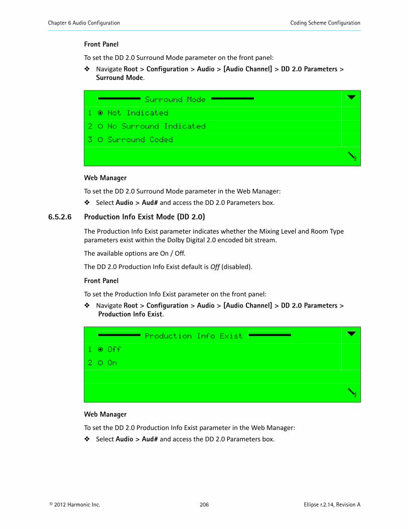
Chapter 6 Audio Configuration Coding Scheme Configuration
© 2012 Harmonic Inc. 206 Ellipse r.2.14, Revision A
Front Panel
To set the DD 2.0 Surround Mode parameter on the front panel: Navigate Root > Configuration > Audio > [Audio Channel] > DD 2.0 Parameters >
Surround Mode.
Web Manager
To set the DD 2.0 Surround Mode parameter in the Web Manager: Select Audio > Aud# and access the DD 2.0 Parameters box.
6.5.2.6 Production Info Exist Mode (DD 2.0)
The Production Info Exist parameter indicates whether the Mixing Level and Room Type parameters exist within the Dolby Digital 2.0 encoded bit stream.
The available options are On / Off.
The DD 2.0 Production Info Exist default is Off (disabled).
Front Panel
To set the Production Info Exist parameter on the front panel: Navigate Root > Configuration > Audio > [Audio Channel] > DD 2.0 Parameters >
Production Info Exist.
Web Manager
To set the DD 2.0 Production Info Exist parameter in the Web Manager: Select Audio > Aud# and access the DD 2.0 Parameters box.
Surround Mode
1 ƒ Not Indicated
2 ‚ No Surround Indicated
3 ‚ Surround Coded
Production Info Exist
1 ƒ Off
2 ‚ On
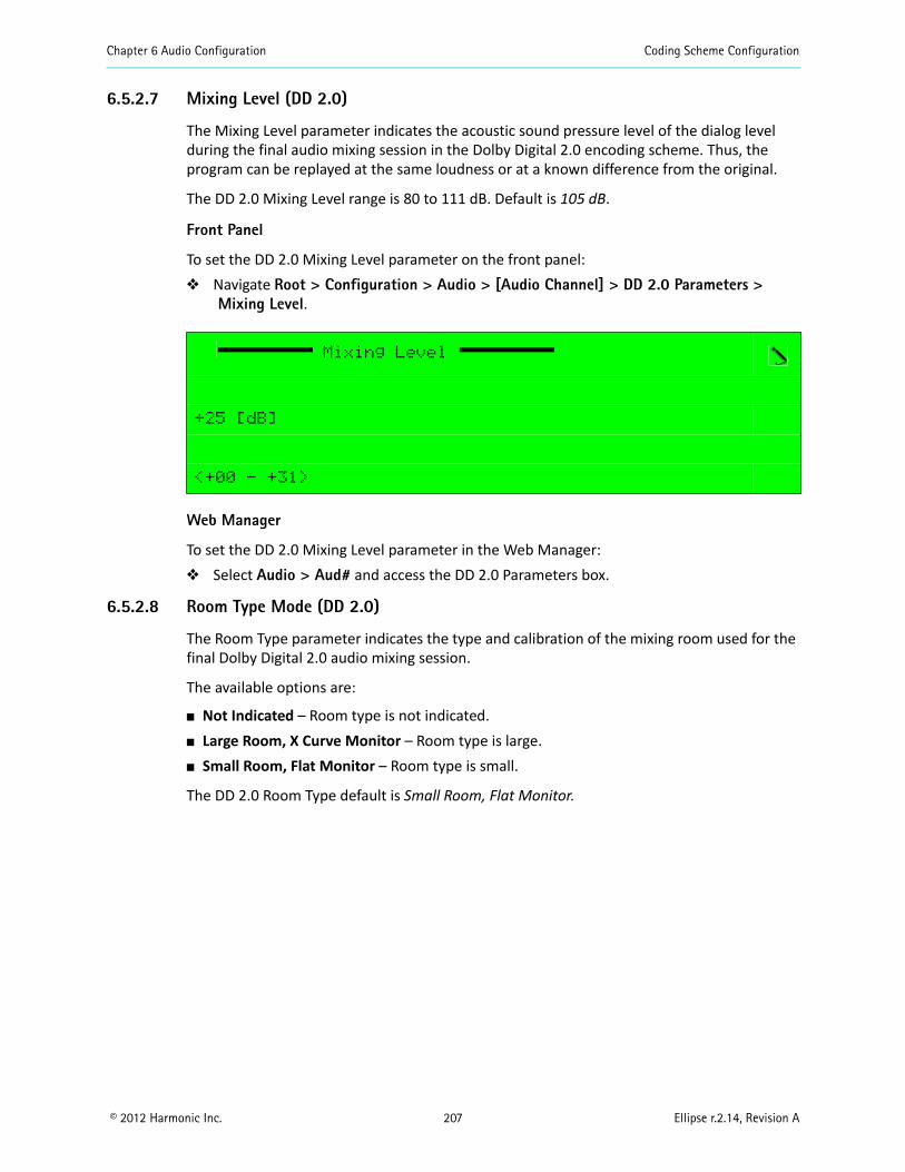
Chapter 6 Audio Configuration Coding Scheme Configuration
© 2012 Harmonic Inc. 207 Ellipse r.2.14, Revision A
6.5.2.7 Mixing Level (DD 2.0)
The Mixing Level parameter indicates the acoustic sound pressure level of the dialog level during the final audio mixing session in the Dolby Digital 2.0 encoding scheme. Thus, the program can be replayed at the same loudness or at a known difference from the original.
The DD 2.0 Mixing Level range is 80 to 111 dB. Default is 105 dB.
Front Panel
To set the DD 2.0 Mixing Level parameter on the front panel: Navigate Root > Configuration > Audio > [Audio Channel] > DD 2.0 Parameters >
Mixing Level.
Web Manager
To set the DD 2.0 Mixing Level parameter in the Web Manager: Select Audio > Aud# and access the DD 2.0 Parameters box.
6.5.2.8 Room Type Mode (DD 2.0)
The Room Type parameter indicates the type and calibration of the mixing room used for the final Dolby Digital 2.0 audio mixing session.
The available options are:
Not Indicated – Room type is not indicated. Large Room, X Curve Monitor – Room type is large. Small Room, Flat Monitor – Room type is small.
The DD 2.0 Room Type default is Small Room, Flat Monitor.
Mixing Level
+25 [dB]
<+00 - +31>
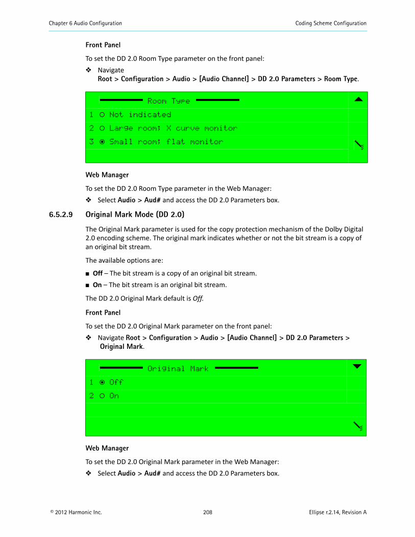
Chapter 6 Audio Configuration Coding Scheme Configuration
© 2012 Harmonic Inc. 208 Ellipse r.2.14, Revision A
Front Panel
To set the DD 2.0 Room Type parameter on the front panel: Navigate
Root > Configuration > Audio > [Audio Channel] > DD 2.0 Parameters > Room Type.
Web Manager
To set the DD 2.0 Room Type parameter in the Web Manager: Select Audio > Aud# and access the DD 2.0 Parameters box.
6.5.2.9 Original Mark Mode (DD 2.0)
The Original Mark parameter is used for the copy protection mechanism of the Dolby Digital 2.0 encoding scheme. The original mark indicates whether or not the bit stream is a copy of an original bit stream.
The available options are:
Off – The bit stream is a copy of an original bit stream. On – The bit stream is an original bit stream.
The DD 2.0 Original Mark default is Off.
Front Panel
To set the DD 2.0 Original Mark parameter on the front panel: Navigate Root > Configuration > Audio > [Audio Channel] > DD 2.0 Parameters >
Original Mark.
Web Manager
To set the DD 2.0 Original Mark parameter in the Web Manager: Select Audio > Aud# and access the DD 2.0 Parameters box.
Room Type
1 ‚ Not indicated
2 ‚ Large room; X curve monitor
3 ƒ Small room; flat monitor
Original Mark
1 ƒ Off
2 ‚ On
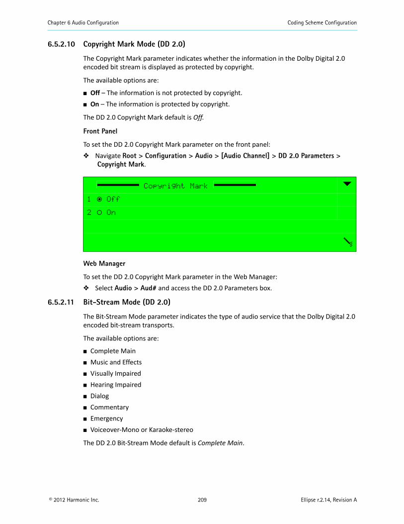
Chapter 6 Audio Configuration Coding Scheme Configuration
© 2012 Harmonic Inc. 209 Ellipse r.2.14, Revision A
6.5.2.10 Copyright Mark Mode (DD 2.0)
The Copyright Mark parameter indicates whether the information in the Dolby Digital 2.0 encoded bit stream is displayed as protected by copyright.
The available options are:
Off – The information is not protected by copyright. On – The information is protected by copyright.
The DD 2.0 Copyright Mark default is Off.
Front Panel
To set the DD 2.0 Copyright Mark parameter on the front panel: Navigate Root > Configuration > Audio > [Audio Channel] > DD 2.0 Parameters >
Copyright Mark.
Web Manager
To set the DD 2.0 Copyright Mark parameter in the Web Manager: Select Audio > Aud# and access the DD 2.0 Parameters box.
6.5.2.11 Bit-Stream Mode (DD 2.0)
The Bit-Stream Mode parameter indicates the type of audio service that the Dolby Digital 2.0 encoded bit-stream transports.
The available options are:
Complete Main Music and Effects Visually Impaired Hearing Impaired Dialog Commentary Emergency Voiceover-Mono or Karaoke-stereo
The DD 2.0 Bit-Stream Mode default is Complete Main.
Copyright Mark
1 ƒ Off
2 ‚ On

Chapter 6 Audio Configuration Coding Scheme Configuration
© 2012 Harmonic Inc. 210 Ellipse r.2.14, Revision A
Front Panel
To set the DD 2.0 Bit-Stream Mode parameter on the front panel: Navigate Root > Configuration > Audio > [Audio Channel] > DD 2.0 Parameters >
Bitstream Mode.
Web Manager
To set the DD 2.0 Bit-Stream Mode parameter in the Web Manager: Select Audio > Aud# and access the DD 2.0 Parameters box.
6.5.2.12 Dialog Normalization Mode (DD 2.0)
The Dialog Normalization parameter indicates how far the average dialog level of the Dolby Digital 2.0 encoded program is below digital 100%. Valid values are 1 to 31, which are interpreted as -1 to -31 dB with respect to digital 100%. This parameter affects the sound reproduction level.
The DD 2.0 Dialog Normalization range is -31 to -1 dB.
Default value is -27 dB.
Bitstream Mode
1 ƒ Complete main
2 ‚ Music and effects
3 ‚ Visually impaired
4 ‚ Hearing impaired
5 ‚ Dialog
6 ‚ Commentary
7 ‚ Emergency
8 ‚ Voiceover-Mono or Karaoke-stereo
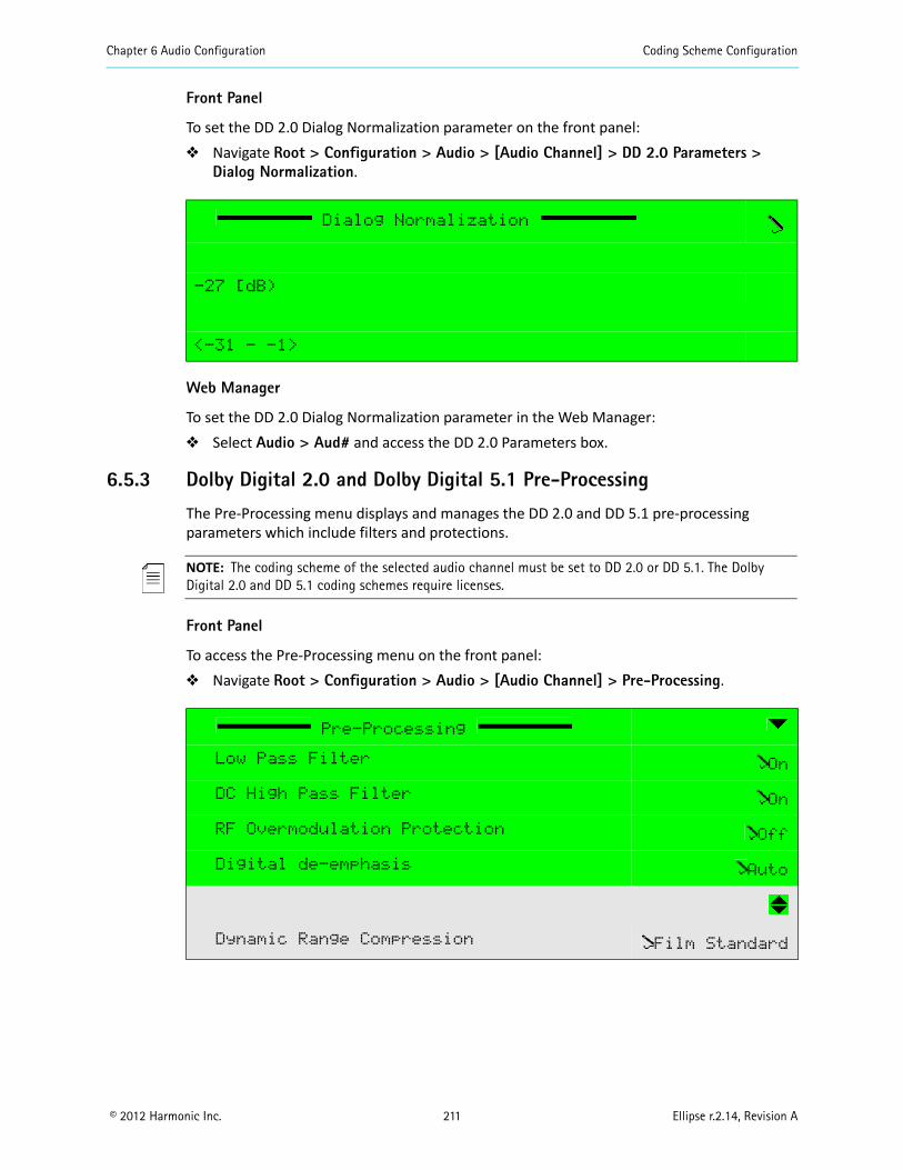
Chapter 6 Audio Configuration Coding Scheme Configuration
© 2012 Harmonic Inc. 211 Ellipse r.2.14, Revision A
Front Panel
To set the DD 2.0 Dialog Normalization parameter on the front panel: Navigate Root > Configuration > Audio > [Audio Channel] > DD 2.0 Parameters >
Dialog Normalization.
Web Manager
To set the DD 2.0 Dialog Normalization parameter in the Web Manager: Select Audio > Aud# and access the DD 2.0 Parameters box.
6.5.3 Dolby Digital 2.0 and Dolby Digital 5.1 Pre-Processing
The Pre-Processing menu displays and manages the DD 2.0 and DD 5.1 pre-processing parameters which include filters and protections.
NOTE: The coding scheme of the selected audio channel must be set to DD 2.0 or DD 5.1. The Dolby Digital 2.0 and DD 5.1 coding schemes require licenses.
Front Panel
To access the Pre-Processing menu on the front panel: Navigate Root > Configuration > Audio > [Audio Channel] > Pre-Processing.
Dialog Normalization
-27 [dB)
<-31 - -1>
Pre-Processing
Low Pass Filter On
DC High Pass Filter On
RF Overmodulation Protection Off
Digital de-emphasis Auto
Dynamic Range Compression Film Standard

Chapter 6 Audio Configuration Coding Scheme Configuration
© 2012 Harmonic Inc. 212 Ellipse r.2.14, Revision A
Web Manager
To access the Pre-Processing menu in the Web Manager: Select Audio > Aud#.
The following sections detail the Dolby Pre-Processing menu options.
6.5.3.1 Low Pass Filter (Dolby Digital 2.0 and Dolby Digital 5.1 Pre-Processing)
The Low-Pass Filter parameter sets the Dolby Digital 2.0 and Dolby Digital 5.1 Pre-Processing low pass filter mode of operation.
The available options are: Off – Low-pass filter is disabled. On – Low-pass filter is enabled.
The Dolby Pre-Processing Low-Pass Filter default is On.
Front Panel
To set the Dolby Pre-Processing Low-Pass Filter parameter on the front panel: Navigate Root > Configuration > Audio > [Audio Channel] > Pre-Processing > Low-
Pass Filter.
Web Manager
To set the Dolby Pre-Processing Low-Pass Filter parameter in the Web Manager: Select Audio > Aud# and access the Pre-Processing parameters box.
Low Pass Filter
‚ Off
ƒ On
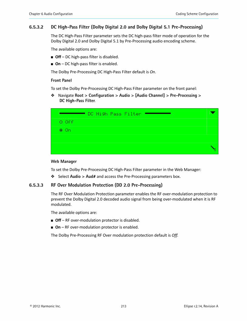
Chapter 6 Audio Configuration Coding Scheme Configuration
© 2012 Harmonic Inc. 213 Ellipse r.2.14, Revision A
6.5.3.2 DC High-Pass Filter (Dolby Digital 2.0 and Dolby Digital 5.1 Pre-Processing)
The DC High-Pass Filter parameter sets the DC high-pass filter mode of operation for the Dolby Digital 2.0 and Dolby Digital 5.1 by Pre-Processing audio encoding scheme.
The available options are:
Off – DC high-pass filter is disabled. On – DC high-pass filter is enabled.
The Dolby Pre-Processing DC High-Pass Filter default is On.
Front Panel
To set the Dolby Pre-Processing DC High-Pass Filter parameter on the front panel: Navigate Root > Configuration > Audio > [Audio Channel] > Pre-Processing >
DC High-Pass Filter.
Web Manager
To set the Dolby Pre-Processing DC High-Pass Filter parameter in the Web Manager: Select Audio > Aud# and access the Pre-Processing parameters box.
6.5.3.3 RF Over Modulation Protection (DD 2.0 Pre-Processing)
The RF Over Modulation Protection parameter enables the RF over-modulation protection to prevent the Dolby Digital 2.0 decoded audio signal from being over-modulated when it is RF modulated.
The available options are:
Off – RF over-modulation protector is disabled. On – RF over-modulation protector is enabled.
The Dolby Pre-Processing RF Over modulation protection default is Off.
DC High Pass Filter
‚ Off
ƒ On
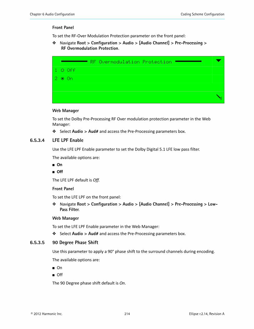
Chapter 6 Audio Configuration Coding Scheme Configuration
© 2012 Harmonic Inc. 214 Ellipse r.2.14, Revision A
Front Panel
To set the RF-Over Modulation Protection parameter on the front panel: Navigate Root > Configuration > Audio > [Audio Channel] > Pre-Processing >
RF Overmodulation Protection.
Web Manager
To set the Dolby Pre-Processing RF Over modulation protection parameter in the Web Manager: Select Audio > Aud# and access the Pre-Processing parameters box.
6.5.3.4 LFE LPF Enable
Use the LFE LPF Enable parameter to set the Dolby Digital 5.1 LFE low pass filter.
The available options are: On Off
The LFE LPF default is Off.
Front Panel
To set the LFE LPF on the front panel: Navigate Root > Configuration > Audio > [Audio Channel] > Pre-Processing > Low-
Pass Filter.
Web Manager
To set the LFE LPF Enable parameter in the Web Manager: Select Audio > Aud# and access the Pre-Processing parameters box.
6.5.3.5 90 Degree Phase Shift
Use this parameter to apply a 90° phase shift to the surround channels during encoding.
The available options are:
On Off
The 90 Degree phase shift default is On.
RF Overmodulation Protection
1 ‚ Off
2 ƒ On
Chapter 6 Audio Configuration Coding Scheme Configuration
© 2012 Harmonic Inc. 215 Ellipse r.2.14, Revision A
Front Panel
To set the 90 Degree phase shift on the front panel: Navigate Root > Configuration > Audio > [Audio Channel] > Pre-Processing > 90
Degree phase shift.
Web Manager
To set the 90 Degree phase shift parameter in the Web Manager: Select Audio > Aud# and access the Pre-Processing parameters box.
6.5.3.6 3dB Attenuation
Use this parameter to reduce the levels of the surround channels to compensate between the calibration of film dubbing stages and consumer replay environments.
The available options are: Off On
The 3dB Attenuation default is Off.
Front Panel
To set the 3dB Attenuation on the front panel: Navigate
Root > Configuration > Audio > [Audio Channel] > Pre-Processing > 3dB attenuation.
Web Manager
To set the 3dB Attenuation parameter in the Web Manager: Select Audio > Aud# and access the Pre-Processing parameters box.
6.5.3.7 Dynamic Range Compression (Dolby Digital 2.0 and Dolby Digital 5.1 Pre-Processing)
The Dynamic Range Compression parameter sets the audio dynamic-range compression profile for the Dolby Digital 2.0 and Dolby Digital 5.1 encoded audio channels. There are six modes of compression profile. This parameter determines the characteristic curve of the dynamic range compression algorithm. Each profile has its own boost, null-band, and cut parameters.
The available options are:
None Film Standard Film Light Music Standard Music Light Speech
The Dolby Pre-Processing Dynamic Range Compression default is Film Standard.
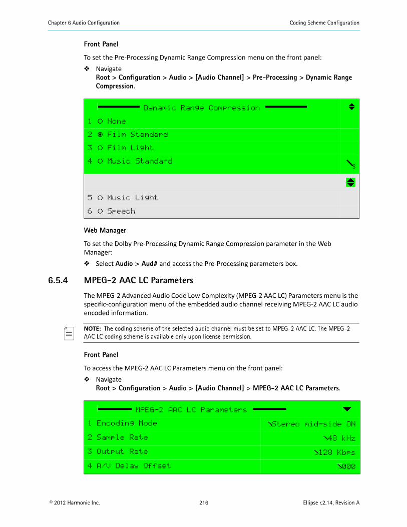
Chapter 6 Audio Configuration Coding Scheme Configuration
© 2012 Harmonic Inc. 216 Ellipse r.2.14, Revision A
Front Panel
To set the Pre-Processing Dynamic Range Compression menu on the front panel: Navigate
Root > Configuration > Audio > [Audio Channel] > Pre-Processing > Dynamic Range Compression.
Web Manager
To set the Dolby Pre-Processing Dynamic Range Compression parameter in the Web Manager: Select Audio > Aud# and access the Pre-Processing parameters box.
6.5.4 MPEG-2 AAC LC Parameters
The MPEG-2 Advanced Audio Code Low Complexity (MPEG-2 AAC LC) Parameters menu is the specific-configuration menu of the embedded audio channel receiving MPEG-2 AAC LC audio encoded information.
NOTE: The coding scheme of the selected audio channel must be set to MPEG-2 AAC LC. The MPEG-2 AAC LC coding scheme is available only upon license permission.
Front Panel
To access the MPEG-2 AAC LC Parameters menu on the front panel: Navigate
Root > Configuration > Audio > [Audio Channel] > MPEG-2 AAC LC Parameters.
Dynamic Range Compression
1 ‚ None
2 ƒ Film Standard
3 ‚ Film Light
4 ‚ Music Standard
5 ‚ Music Light
6 ‚ Speech
MPEG-2 AAC LC Parameters
1 Encoding Mode Stereo mid-side ON
2 Sample Rate 48 kHz
3 Output Rate 128 Kbps
4 A/V Delay Offset 000
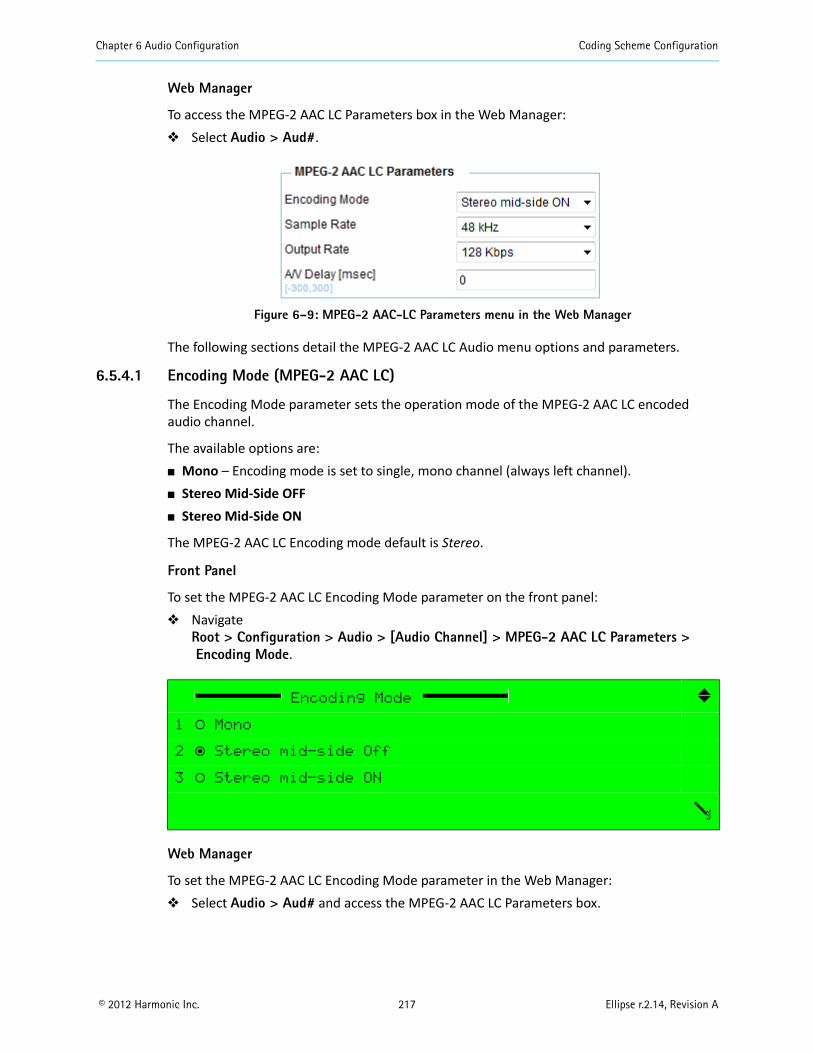
Chapter 6 Audio Configuration Coding Scheme Configuration
© 2012 Harmonic Inc. 217 Ellipse r.2.14, Revision A
Web Manager
To access the MPEG-2 AAC LC Parameters box in the Web Manager: Select Audio > Aud#.
Figure 6–9: MPEG-2 AAC-LC Parameters menu in the Web Manager
The following sections detail the MPEG-2 AAC LC Audio menu options and parameters.
6.5.4.1 Encoding Mode (MPEG-2 AAC LC)
The Encoding Mode parameter sets the operation mode of the MPEG-2 AAC LC encoded audio channel.
The available options are: Mono – Encoding mode is set to single, mono channel (always left channel). Stereo Mid-Side OFF Stereo Mid-Side ON
The MPEG-2 AAC LC Encoding mode default is Stereo.
Front Panel
To set the MPEG-2 AAC LC Encoding Mode parameter on the front panel: Navigate
Root > Configuration > Audio > [Audio Channel] > MPEG-2 AAC LC Parameters >Encoding Mode.
Web Manager
To set the MPEG-2 AAC LC Encoding Mode parameter in the Web Manager: Select Audio > Aud# and access the MPEG-2 AAC LC Parameters box.
Encoding Mode
1 ‚ Mono
2 ƒ Stereo mid-side Off
3 ‚ Stereo mid-side ON
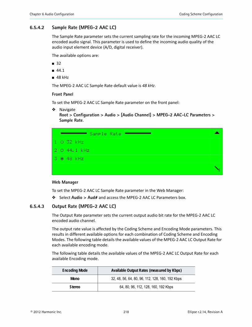
Chapter 6 Audio Configuration Coding Scheme Configuration
© 2012 Harmonic Inc. 218 Ellipse r.2.14, Revision A
6.5.4.2 Sample Rate (MPEG-2 AAC LC)
The Sample Rate parameter sets the current sampling rate for the incoming MPEG-2 AAC LC encoded audio signal. This parameter is used to define the incoming audio quality of the audio input element device (A/D, digital receiver).
The available options are:
32 44.1 48 kHz
The MPEG-2 AAC LC Sample Rate default value is 48 kHz.
Front Panel
To set the MPEG-2 AAC LC Sample Rate parameter on the front panel: Navigate
Root > Configuration > Audio > [Audio Channel] > MPEG-2 AAC-LC Parameters >Sample Rate.
Web Manager
To set the MPEG-2 AAC LC Sample Rate parameter in the Web Manager: Select Audio > Aud# and access the MPEG-2 AAC LC Parameters box.
6.5.4.3 Output Rate (MPEG-2 AAC LC)
The Output Rate parameter sets the current output audio bit rate for the MPEG-2 AAC LC encoded audio channel.
The output rate value is affected by the Coding Scheme and Encoding Mode parameters. This results in different available options for each combination of Coding Scheme and Encoding Modes. The following table details the available values of the MPEG-2 AAC LC Output Rate for each available encoding mode.
The following table details the available values of the MPEG-2 AAC LC Output Rate for each available Encoding mode.
Sample Rate
1 ‚ 32 kHz
2 ‚ 44.1 kHz
3 ƒ 48 kHz
Encoding Mode Available Output Rates (measured by Kbps)
Mono 32, 48, 56, 64, 80, 96, 112, 128, 160, 192 Kbps
Stereo 64, 80, 96, 112, 128, 160, 192 Kbps
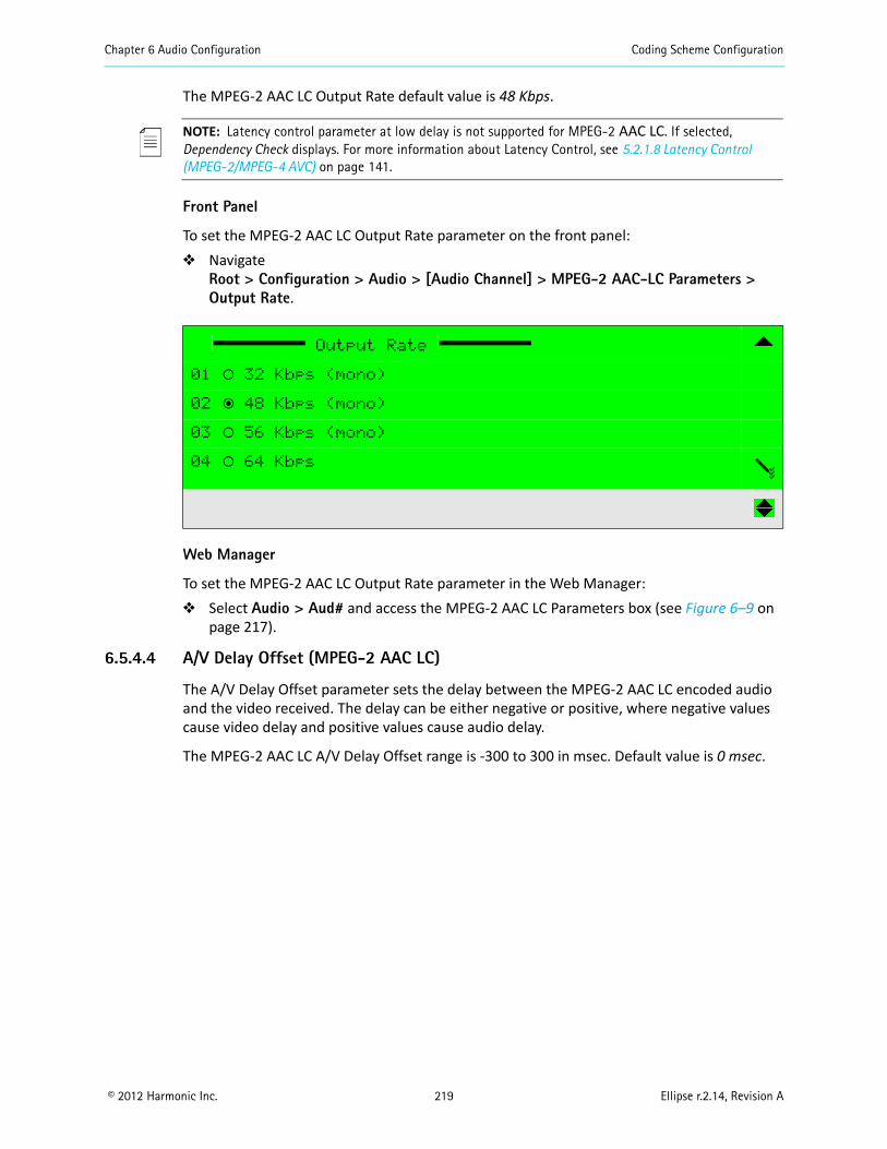
Chapter 6 Audio Configuration Coding Scheme Configuration
© 2012 Harmonic Inc. 219 Ellipse r.2.14, Revision A
The MPEG-2 AAC LC Output Rate default value is 48 Kbps.
NOTE: Latency control parameter at low delay is not supported for MPEG-2 AAC LC. If selected, Dependency Check displays. For more information about Latency Control, see 5.2.1.8 Latency Control (MPEG-2/MPEG-4 AVC) on page 141.
Front Panel
To set the MPEG-2 AAC LC Output Rate parameter on the front panel: Navigate
Root > Configuration > Audio > [Audio Channel] > MPEG-2 AAC-LC Parameters >Output Rate.
Web Manager
To set the MPEG-2 AAC LC Output Rate parameter in the Web Manager: Select Audio > Aud# and access the MPEG-2 AAC LC Parameters box (see Figure 6–9 on
page 217).
6.5.4.4 A/V Delay Offset (MPEG-2 AAC LC)
The A/V Delay Offset parameter sets the delay between the MPEG-2 AAC LC encoded audio and the video received. The delay can be either negative or positive, where negative values cause video delay and positive values cause audio delay.
The MPEG-2 AAC LC A/V Delay Offset range is -300 to 300 in msec. Default value is 0 msec.
Output Rate
01 ‚ 32 Kbps (mono)
02 ƒ 48 Kbps (mono)
03 ‚ 56 Kbps (mono)
04 ‚ 64 Kbps
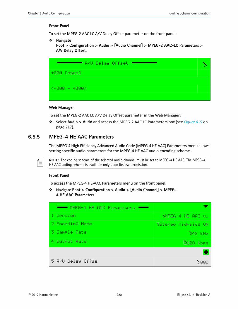
Chapter 6 Audio Configuration Coding Scheme Configuration
© 2012 Harmonic Inc. 220 Ellipse r.2.14, Revision A
Front Panel
To set the MPEG-2 AAC LC A/V Delay Offset parameter on the front panel: Navigate
Root > Configuration > Audio > [Audio Channel] > MPEG-2 AAC-LC Parameters >A/V Delay Offset.
Web Manager
To set the MPEG-2 AAC LC A/V Delay Offset parameter in the Web Manager: Select Audio > Aud# and access the MPEG-2 AAC LC Parameters box (see Figure 6–9 on
page 217).
6.5.5 MPEG-4 HE AAC Parameters
The MPEG-4 High Efficiency Advanced Audio Code (MPEG-4 HE AAC) Parameters menu allows setting specific audio parameters for the MPEG-4 HE AAC audio encoding scheme.
NOTE: The coding scheme of the selected audio channel must be set to MPEG-4 HE AAC. The MPEG-4 HE AAC coding scheme is available only upon license permission.
Front Panel
To access the MPEG-4 HE-AAC Parameters menu on the front panel: Navigate Root > Configuration > Audio > [Audio Channel] > MPEG-
4 HE AAC Parameters.
A/V Delay Offset
+000 [msec]
<-300 - +300>
MPEG-4 HE AAC Parameters
1 Version MPEG-4 HE AAC v1
2 Encoding Mode Stereo mid-side ON
3 Sample Rate 48 kHz
4 Output Rate 128 Kbps
5 A/V Delay Offse 000
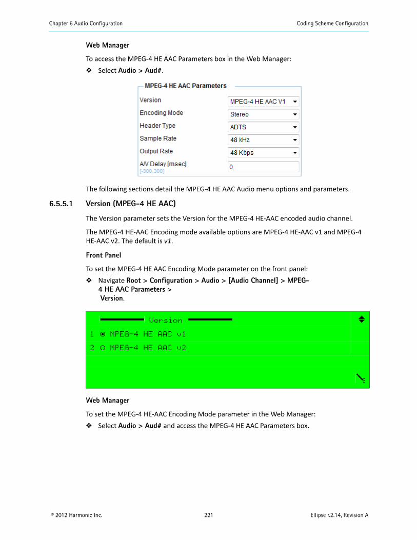
Chapter 6 Audio Configuration Coding Scheme Configuration
© 2012 Harmonic Inc. 221 Ellipse r.2.14, Revision A
Web Manager
To access the MPEG-4 HE AAC Parameters box in the Web Manager: Select Audio > Aud#.
The following sections detail the MPEG-4 HE AAC Audio menu options and parameters.
6.5.5.1 Version (MPEG-4 HE AAC)
The Version parameter sets the Version for the MPEG-4 HE-AAC encoded audio channel.
The MPEG-4 HE-AAC Encoding mode available options are MPEG-4 HE-AAC v1 and MPEG-4 HE-AAC v2. The default is v1.
Front Panel
To set the MPEG-4 HE AAC Encoding Mode parameter on the front panel: Navigate Root > Configuration > Audio > [Audio Channel] > MPEG-
4 HE AAC Parameters >Version.
Web Manager
To set the MPEG-4 HE-AAC Encoding Mode parameter in the Web Manager: Select Audio > Aud# and access the MPEG-4 HE AAC Parameters box.
Version
1 ƒ MPEG-4 HE AAC v1
2 ‚ MPEG-4 HE AAC v2

Chapter 6 Audio Configuration Coding Scheme Configuration
© 2012 Harmonic Inc. 222 Ellipse r.2.14, Revision A
6.5.5.2 Encoding Mode (MPEG-4 HE AAC)
The Encoding Mode parameter sets the operation mode of the MPEG-4 HE-AAC encoded audio channel.
The available options are:
Mono – Encoding mode is set to single, mono channel. Mono channel is always left. Stereo – Encoding mode is stereo.
The MPEG-4 HE AAC Encoding mode default is Stereo.
Front Panel
To set the MPEG-4 HE AAC Encoding Mode parameter on the front panel: Navigate Root > Configuration > Audio > [Audio Channel] > MPEG-
4 HE AAC Parameters >Encoding Mode.
Web Manager
To set the MPEG-4 HE AAC Encoding Mode parameter in the Web Manager: Select Audio > Aud# and access the MPEG-4 HE AAC Parameters box.
Encoding Mode
1 ‚ Mono
2 ƒ Stereo
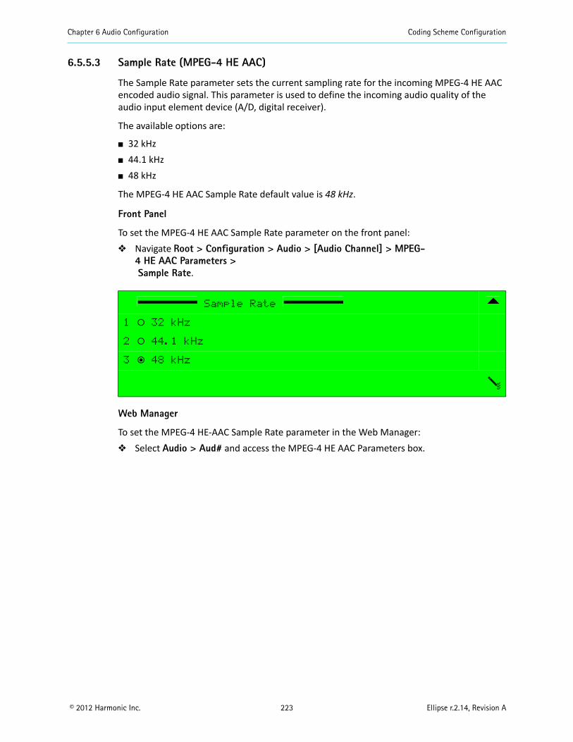
Chapter 6 Audio Configuration Coding Scheme Configuration
© 2012 Harmonic Inc. 223 Ellipse r.2.14, Revision A
6.5.5.3 Sample Rate (MPEG-4 HE AAC)
The Sample Rate parameter sets the current sampling rate for the incoming MPEG-4 HE AAC encoded audio signal. This parameter is used to define the incoming audio quality of the audio input element device (A/D, digital receiver).
The available options are:
32 kHz 44.1 kHz 48 kHz
The MPEG-4 HE AAC Sample Rate default value is 48 kHz.
Front Panel
To set the MPEG-4 HE AAC Sample Rate parameter on the front panel: Navigate Root > Configuration > Audio > [Audio Channel] > MPEG-
4 HE AAC Parameters >Sample Rate.
Web Manager
To set the MPEG-4 HE-AAC Sample Rate parameter in the Web Manager: Select Audio > Aud# and access the MPEG-4 HE AAC Parameters box.
Sample Rate
1 ‚ 32 kHz
2 ‚ 44.1 kHz
3 ƒ 48 kHz
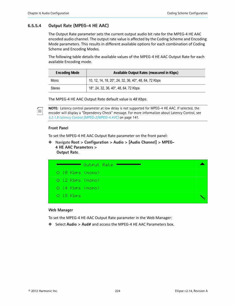
Chapter 6 Audio Configuration Coding Scheme Configuration
© 2012 Harmonic Inc. 224 Ellipse r.2.14, Revision A
6.5.5.4 Output Rate (MPEG-4 HE AAC)
The Output Rate parameter sets the current output audio bit rate for the MPEG-4 HE AAC encoded audio channel. The output rate value is affected by the Coding Scheme and Encoding Mode parameters. This results in different available options for each combination of Coding Scheme and Encoding Modes.
The following table details the available values of the MPEG-4 HE AAC Output Rate for each available Encoding mode.
The MPEG-4 HE AAC Output Rate default value is 48 Kbps.
NOTE: Latency control parameter at low delay is not supported for MPEG-4 HE AAC. If selected, the encoder will display a “Dependency Check” message. For more information about Latency Control, see 5.2.1.8 Latency Control (MPEG-2/MPEG-4 AVC) on page 141.
Front Panel
To set the MPEG-4 HE AAC Output Rate parameter on the front panel: Navigate Root > Configuration > Audio > [Audio Channel] > MPEG-
4 HE AAC Parameters >Output Rate.
Web Manager
To set the MPEG-4 HE-AAC Output Rate parameter in the Web Manager: Select Audio > Aud# and access the MPEG-4 HE AAC Parameters box.
Encoding Mode Available Output Rates (measured in Kbps)
Mono 10, 12, 14, 18, 20*, 24, 32, 36, 40*, 48, 64, 72 Kbps
Stereo 18*, 24, 32, 36, 40*, 48, 64, 72 Kbps
Output Rate
‚ 10 Kbps (mono)
‚ 12 Kbps (mono)
‚ 14 Kbps (mono)
‚ 18 Kbps
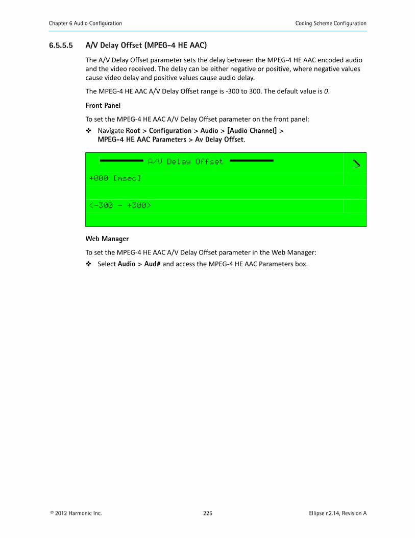
Chapter 6 Audio Configuration Coding Scheme Configuration
© 2012 Harmonic Inc. 225 Ellipse r.2.14, Revision A
6.5.5.5 A/V Delay Offset (MPEG-4 HE AAC)
The A/V Delay Offset parameter sets the delay between the MPEG-4 HE AAC encoded audio and the video received. The delay can be either negative or positive, where negative values cause video delay and positive values cause audio delay.
The MPEG-4 HE AAC A/V Delay Offset range is -300 to 300. The default value is 0.
Front Panel
To set the MPEG-4 HE AAC A/V Delay Offset parameter on the front panel: Navigate Root > Configuration > Audio > [Audio Channel] >
MPEG-4 HE AAC Parameters > Av Delay Offset.
Web Manager
To set the MPEG-4 HE AAC A/V Delay Offset parameter in the Web Manager: Select Audio > Aud# and access the MPEG-4 HE AAC Parameters box.
A/V Delay Offset
+000 [msec]
<-300 - +300>
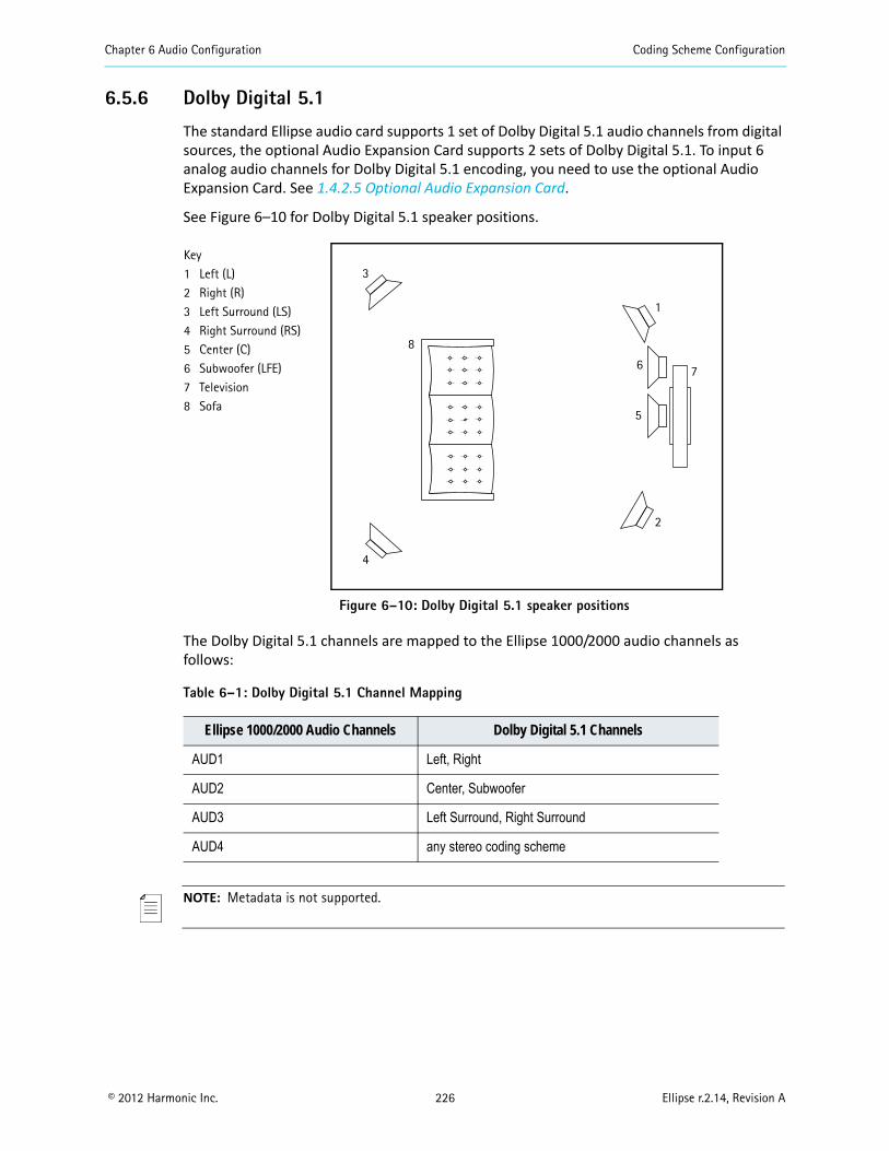
Chapter 6 Audio Configuration Coding Scheme Configuration
© 2012 Harmonic Inc. 226 Ellipse r.2.14, Revision A
6.5.6 Dolby Digital 5.1
The standard Ellipse audio card supports 1 set of Dolby Digital 5.1 audio channels from digital sources, the optional Audio Expansion Card supports 2 sets of Dolby Digital 5.1. To input 6 analog audio channels for Dolby Digital 5.1 encoding, you need to use the optional Audio Expansion Card. See 1.4.2.5 Optional Audio Expansion Card.
See Figure 6–10 for Dolby Digital 5.1 speaker positions.
Figure 6–10: Dolby Digital 5.1 speaker positions
The Dolby Digital 5.1 channels are mapped to the Ellipse 1000/2000 audio channels as follows:
NOTE: Metadata is not supported.
Table 6–1: Dolby Digital 5.1 Channel Mapping
Ellipse 1000/2000 Audio Channels Dolby Digital 5.1 Channels
AUD1 Left, Right
AUD2 Center, Subwoofer
AUD3 Left Surround, Right Surround
AUD4 any stereo coding scheme
Key1 Left (L)2 Right (R)3 Left Surround (LS)4 Right Surround (RS)5 Center (C)6 Subwoofer (LFE)7 Television8 Sofa
3
4
1
2
6
5
7
8
Chapter 6 Audio Configuration Coding Scheme Configuration
© 2012 Harmonic Inc. 227 Ellipse r.2.14, Revision A
6.5.6.1 Configuring Dolby Digital 5.1
Front Panel
To configure an audio channel with the Dolby Digital 5.1 coding scheme on the front panel:1. On the front panel navigate Root > Configuration > Audio.2. If you are using the standard XLR audio card, select the AUD1 audio channel, if you are
using the Audio Expansion Card you can select the AUD1 or the AUD5 audio channel.The following two audio channels are reserved automatically, therefore AUD2-AUD3 if you selected AUD1 and AUD6-AUD7 if you selected AUD5.
3. Select the General menu.4. Select the Coding Scheme menu.5. Select DD 5.1.6. Press F1 to save.
Web Manager
To configure an audio channel with the Dolby Digital 5.1 coding scheme in the Web Manager:1. In the Web Manager select Audio > Aud#.2. If you are using the standard XLR audio card, select the AUD1 audio channel tab, if you
are using the Audio Expansion Card you can select the AUD1 or the AUD5 audio channel tab.The following two audio channels are reserved automatically, therefore AUD2-AUD3 if you selected AUD1 and AUD6-AUD7 if you selected AUD5.
3. In the General box select DD 5.1 for the coding scheme.4. Save your changes.
6.5.6.2 DD 5.1 Parameters
Accessing the DD 5.1 Parameters
Sample Rate (DD 5.1)
Use this parameter to choose one of the following sample rates:
32 kHz
44.1 kHz
48 kHz
The default sample rate is 48 kHz.
Output Rate (DD 5.1)
Use this parameter to choose an output rate from a list of rates ranging from 224 kbps to 640 kbps.
The default output rate is 256 kbps.
Chapter 6 Audio Configuration Coding Scheme Configuration
© 2012 Harmonic Inc. 228 Ellipse r.2.14, Revision A
A/V Delay (DD 5.1)
Use this parameter to delay the audio or video to correct synchronization between the audio and video. Enter a positive value in milliseconds to delay the audio or a negative value in milliseconds to delay the video.
The default audio/video delay is 0 milliseconds.
Production Info Exist (DD 5.1)
Use this parameter to enable or disable the inclusion of the Mixing Level and Room Type parameters in the Dolby Digital 5.1 encoded bit stream.
The Production info exist default is On.
Mixing Level (DD 5.1)
Use this parameter to enter a mixing level in decibels. The Mixing Level parameter indicates the acoustic sound pressure level of the dialog during the final audio mixing session in the Dolby Digital 5.1 encoding scheme. Thus, the program can be replayed at the same loudness or at a known difference from the original.
The Mixing Level range is 80 to 111. The default is 25.
Room Type (DD 5.1)
Use this parameter to indicate the type and calibration of the mixing room used for the final Dolby Digital 5.1 audio mixing session.
Choose one of the following:
Not indicated
Large room, X curve mon
Small room, flat monitor
The Room Type default is Small room, flat monitor.
Original Mark (DD 5.1)
Use this parameter to indicate the copy protection mechanism. The original mark indicates whether or not the bit stream is a copy of an original bit stream.
Choose one of the following:
On
Off
The Original mark default is On.
Copyright Mark (DD 5.1)
Use this parameter to indicate whether the information in the bit stream is displayed according to copyright protection laws.
Choose one of the following:
On
Off
The Copyright mark default is On.
Chapter 6 Audio Configuration Coding Scheme Configuration
© 2012 Harmonic Inc. 229 Ellipse r.2.14, Revision A
Bitstream Mode (DD 5.1)
Use this parameter to indicate the type of audio service that the Dolby Digital 5.1 encoded bit-stream transports.
Choose one of the following:
Complete Main Music and effects Visually impaired Hearing impaired Dialog Commentary Emergency Voice over-mono or Kara
The Bitstream Mode default is Complete Main.
Dialog Normalization (DD 5.1)
Use this parameter to indicate how far the average dialog level of the Dolby Digital 5.1 encoded program is below digital 100%. Valid values are -31 to -1. -1 Is equal to 100%. This parameter affects the sound reproduction level.
The Dialog Normalization default is -27.
LFE channel (DD 5.1)
Use this parameter to enable or disable the LFE channel.
Extended BSI (DD 5.1)
Use this parameter to enable or disable the Extended Bitstream.
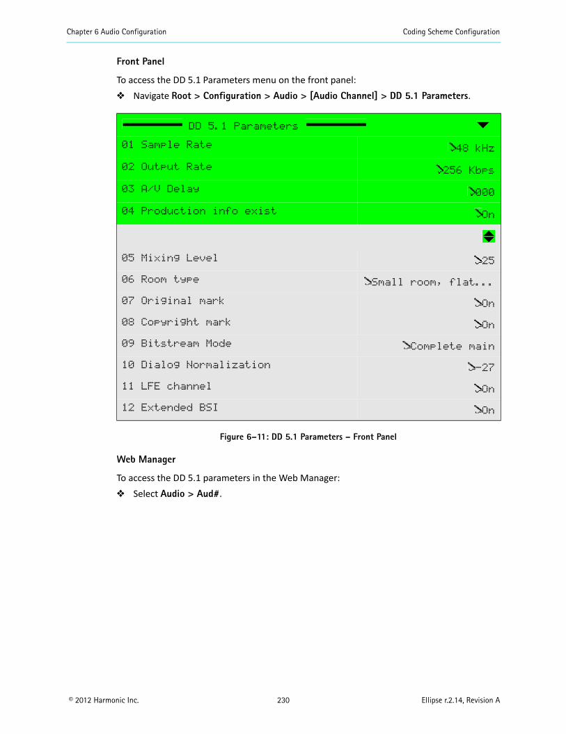
Chapter 6 Audio Configuration Coding Scheme Configuration
© 2012 Harmonic Inc. 230 Ellipse r.2.14, Revision A
Front Panel
To access the DD 5.1 Parameters menu on the front panel: Navigate Root > Configuration > Audio > [Audio Channel] > DD 5.1 Parameters.
Figure 6–11: DD 5.1 Parameters – Front Panel
Web Manager
To access the DD 5.1 parameters in the Web Manager: Select Audio > Aud#.
DD 5.1 Parameters
01 Sample Rate 48 kHz
02 Output Rate 256 Kbps
03 A/V Delay 000
04 Production info exist On
05 Mixing Level 25
06 Room type Small room, flat...
07 Original mark On
08 Copyright mark On
09 Bitstream Mode Complete main
10 Dialog Normalization -27
11 LFE channel On
12 Extended BSI On
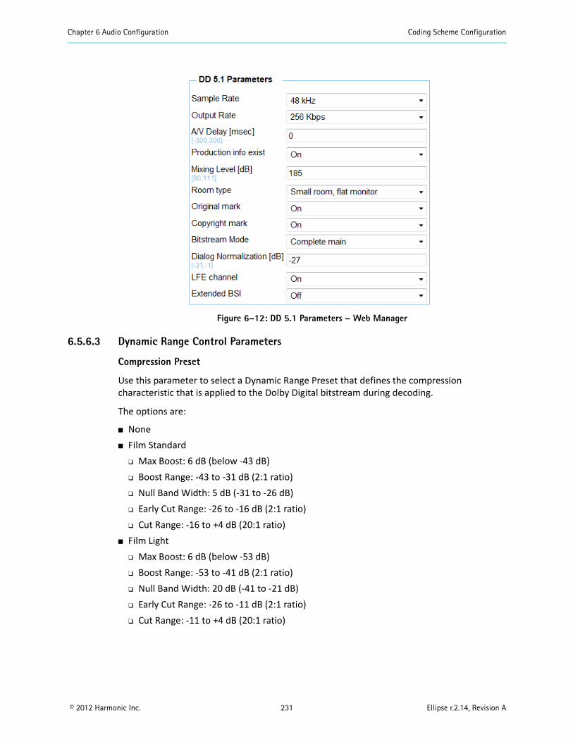
Chapter 6 Audio Configuration Coding Scheme Configuration
© 2012 Harmonic Inc. 231 Ellipse r.2.14, Revision A
Figure 6–12: DD 5.1 Parameters – Web Manager
6.5.6.3 Dynamic Range Control Parameters
Compression Preset
Use this parameter to select a Dynamic Range Preset that defines the compression characteristic that is applied to the Dolby Digital bitstream during decoding.
The options are:
None Film Standard
Max Boost: 6 dB (below -43 dB) Boost Range: -43 to -31 dB (2:1 ratio) Null Band Width: 5 dB (-31 to -26 dB) Early Cut Range: -26 to -16 dB (2:1 ratio) Cut Range: -16 to +4 dB (20:1 ratio)
Film Light Max Boost: 6 dB (below -53 dB) Boost Range: -53 to -41 dB (2:1 ratio) Null Band Width: 20 dB (-41 to -21 dB) Early Cut Range: -26 to -11 dB (2:1 ratio) Cut Range: -11 to +4 dB (20:1 ratio)
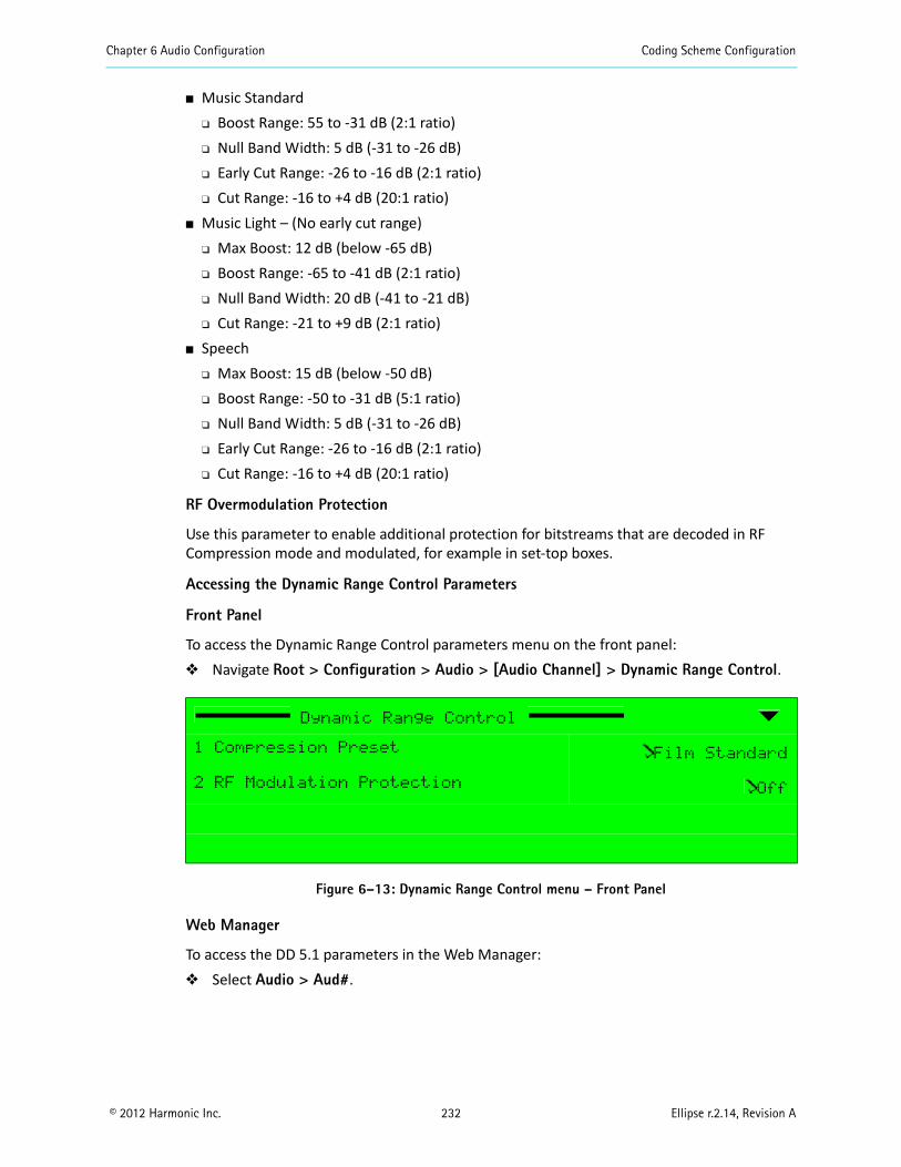
Chapter 6 Audio Configuration Coding Scheme Configuration
© 2012 Harmonic Inc. 232 Ellipse r.2.14, Revision A
Music Standard Boost Range: 55 to -31 dB (2:1 ratio) Null Band Width: 5 dB (-31 to -26 dB) Early Cut Range: -26 to -16 dB (2:1 ratio) Cut Range: -16 to +4 dB (20:1 ratio)
Music Light – (No early cut range) Max Boost: 12 dB (below -65 dB) Boost Range: -65 to -41 dB (2:1 ratio) Null Band Width: 20 dB (-41 to -21 dB) Cut Range: -21 to +9 dB (2:1 ratio)
Speech Max Boost: 15 dB (below -50 dB) Boost Range: -50 to -31 dB (5:1 ratio) Null Band Width: 5 dB (-31 to -26 dB) Early Cut Range: -26 to -16 dB (2:1 ratio) Cut Range: -16 to +4 dB (20:1 ratio)
RF Overmodulation Protection
Use this parameter to enable additional protection for bitstreams that are decoded in RF Compression mode and modulated, for example in set-top boxes.
Accessing the Dynamic Range Control Parameters
Front Panel
To access the Dynamic Range Control parameters menu on the front panel: Navigate Root > Configuration > Audio > [Audio Channel] > Dynamic Range Control.
Figure 6–13: Dynamic Range Control menu – Front Panel
Web Manager
To access the DD 5.1 parameters in the Web Manager: Select Audio > Aud#.
Dynamic Range Control
1 Compression Preset Film Standard
2 RF Modulation Protection Off
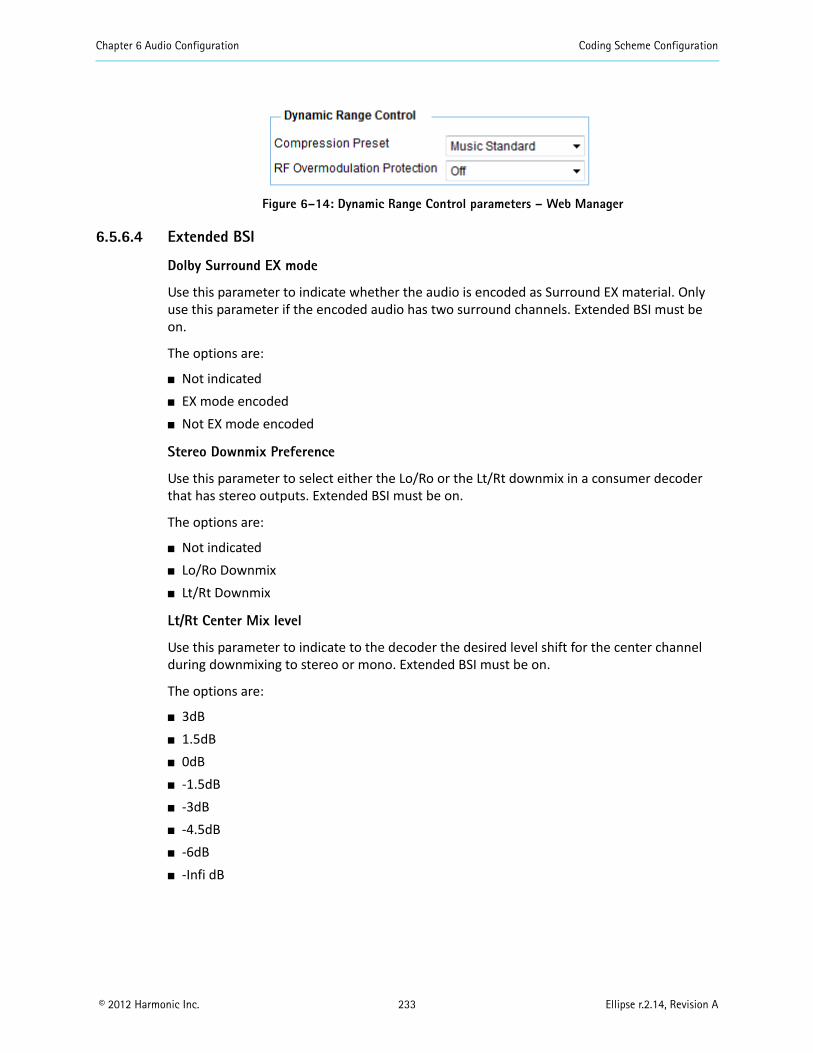
Chapter 6 Audio Configuration Coding Scheme Configuration
© 2012 Harmonic Inc. 233 Ellipse r.2.14, Revision A
Figure 6–14: Dynamic Range Control parameters – Web Manager
6.5.6.4 Extended BSI
Dolby Surround EX mode
Use this parameter to indicate whether the audio is encoded as Surround EX material. Only use this parameter if the encoded audio has two surround channels. Extended BSI must be on.
The options are:
Not indicated EX mode encoded Not EX mode encoded
Stereo Downmix Preference
Use this parameter to select either the Lo/Ro or the Lt/Rt downmix in a consumer decoder that has stereo outputs. Extended BSI must be on.
The options are:
Not indicated Lo/Ro Downmix Lt/Rt Downmix
Lt/Rt Center Mix level
Use this parameter to indicate to the decoder the desired level shift for the center channel during downmixing to stereo or mono. Extended BSI must be on.
The options are:
3dB 1.5dB 0dB -1.5dB -3dB -4.5dB -6dB -Infi dB
Chapter 6 Audio Configuration Coding Scheme Configuration
© 2012 Harmonic Inc. 234 Ellipse r.2.14, Revision A
Lt/Rt Surround Mix level
Use this parameter to indicate to the decoder the desired level shift for the surround channels during downmixing to stereo or mono. Extended BSI must be on.
The options are:
-1.5dB -3dB -4.5dB -6dB -Infi dB
Lo/Ro Center Mix level
Use this parameter to indicate to the decoder the desired level shift for the center channel during downmixing to stereo or mono. Extended BSI must be on.
The options are:
3dB 1.5dB 0dB -1.5dB -3dB -4.5dB -6dB -Infi dB
Lo/Ro Surround Mix level
Use this parameter to indicate to the decoder the desired level shift for the surround channels during downmixing to stereo or mono. Extended BSI must be on.
The options are:
-1.5dB -3dB -4.5dB -6dB -Infi dB
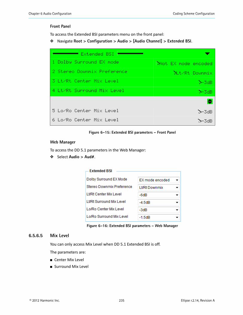
Chapter 6 Audio Configuration Coding Scheme Configuration
© 2012 Harmonic Inc. 235 Ellipse r.2.14, Revision A
Front Panel
To access the Extended BSI parameters menu on the front panel: Navigate Root > Configuration > Audio > [Audio Channel] > Extended BSI.
Figure 6–15: Extended BSI parameters – Front Panel
Web Manager
To access the DD 5.1 parameters in the Web Manager: Select Audio > Aud#.
Figure 6–16: Extended BSI parameters – Web Manager
6.5.6.5 Mix Level
You can only access Mix Level when DD 5.1 Extended BSI is off.
The parameters are:
Center Mix Level Surround Mix Level
Extended BSI
1 Dolby Surround EX mode Not EX mode encoded
2 Stereo Downmix Preference Lt/Rt Downmix
3 Lt/Rt Center Mix Level -3dB
4 Lt/Rt Surround Mix Level -3dB
5 Lo/Ro Center Mix Level -3dB
6 Lo/Ro Center Mix Level -3dB
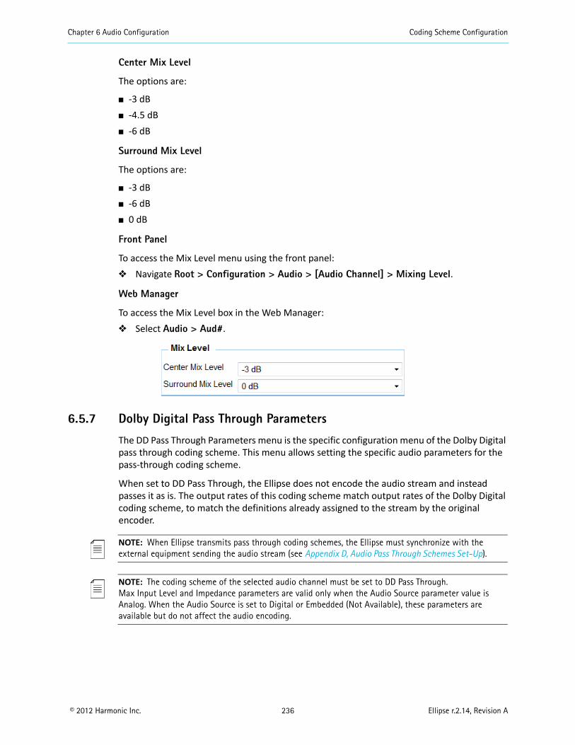
Chapter 6 Audio Configuration Coding Scheme Configuration
© 2012 Harmonic Inc. 236 Ellipse r.2.14, Revision A
Center Mix Level
The options are:
-3 dB -4.5 dB -6 dB
Surround Mix Level
The options are:
-3 dB -6 dB 0 dB
Front Panel
To access the Mix Level menu using the front panel: Navigate Root > Configuration > Audio > [Audio Channel] > Mixing Level.
Web Manager
To access the Mix Level box in the Web Manager: Select Audio > Aud#.
6.5.7 Dolby Digital Pass Through Parameters
The DD Pass Through Parameters menu is the specific configuration menu of the Dolby Digital pass through coding scheme. This menu allows setting the specific audio parameters for the pass-through coding scheme.
When set to DD Pass Through, the Ellipse does not encode the audio stream and instead passes it as is. The output rates of this coding scheme match output rates of the Dolby Digital coding scheme, to match the definitions already assigned to the stream by the original encoder.
NOTE: When Ellipse transmits pass through coding schemes, the Ellipse must synchronize with the external equipment sending the audio stream (see Appendix D, Audio Pass Through Schemes Set-Up).
NOTE: The coding scheme of the selected audio channel must be set to DD Pass Through.Max Input Level and Impedance parameters are valid only when the Audio Source parameter value is Analog. When the Audio Source is set to Digital or Embedded (Not Available), these parameters are available but do not affect the audio encoding.
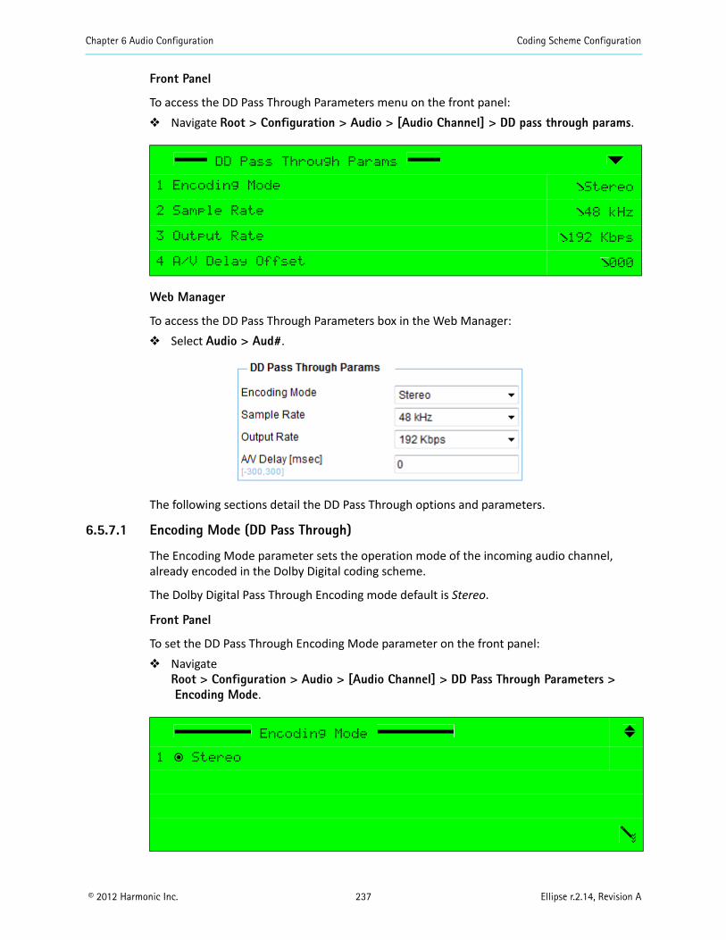
Chapter 6 Audio Configuration Coding Scheme Configuration
© 2012 Harmonic Inc. 237 Ellipse r.2.14, Revision A
Front Panel
To access the DD Pass Through Parameters menu on the front panel: Navigate Root > Configuration > Audio > [Audio Channel] > DD pass through params.
Web Manager
To access the DD Pass Through Parameters box in the Web Manager: Select Audio > Aud#.
The following sections detail the DD Pass Through options and parameters.
6.5.7.1 Encoding Mode (DD Pass Through)
The Encoding Mode parameter sets the operation mode of the incoming audio channel, already encoded in the Dolby Digital coding scheme.
The Dolby Digital Pass Through Encoding mode default is Stereo.
Front Panel
To set the DD Pass Through Encoding Mode parameter on the front panel: Navigate
Root > Configuration > Audio > [Audio Channel] > DD Pass Through Parameters >Encoding Mode.
DD Pass Through Params
1 Encoding Mode Stereo
2 Sample Rate 48 kHz
3 Output Rate 192 Kbps
4 A/V Delay Offset 000
Encoding Mode
1 ƒ Stereo
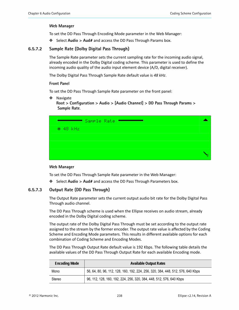
Chapter 6 Audio Configuration Coding Scheme Configuration
© 2012 Harmonic Inc. 238 Ellipse r.2.14, Revision A
Web Manager
To set the DD Pass Through Encoding Mode parameter in the Web Manager: Select Audio > Aud# and access the DD Pass Through Params box.
6.5.7.2 Sample Rate (Dolby Digital Pass Through)
The Sample Rate parameter sets the current sampling rate for the incoming audio signal, already encoded in the Dolby Digital coding scheme. This parameter is used to define the incoming audio quality of the audio input element device (A/D, digital receiver).
The Dolby Digital Pass Through Sample Rate default value is 48 kHz.
Front Panel
To set the DD Pass Through Sample Rate parameter on the front panel: Navigate
Root > Configuration > Audio > [Audio Channel] > DD Pass Through Params >Sample Rate.
Web Manager
To set the DD Pass Through Sample Rate parameter in the Web Manager: Select Audio > Aud# and access the DD Pass Through Parameters box.
6.5.7.3 Output Rate (DD Pass Through)
The Output Rate parameter sets the current output audio bit rate for the Dolby Digital Pass Through audio channel.
The DD Pass Through scheme is used when the Ellipse receives on audio stream, already encoded in the Dolby Digital coding scheme.
The output rate of the Dolby Digital Pass Through must be set according to the output rate assigned to the stream by the former encoder. The output rate value is affected by the Coding Scheme and Encoding Mode parameters. This results in different available options for each combination of Coding Scheme and Encoding Modes.
The DD Pass Through Output Rate default value is 192 Kbps. The following table details the available values of the DD Pass Through Output Rate for each available Encoding mode.
Sample Rate
ƒ 48 kHz
Encoding Mode Available Output Rates
Mono 56, 64, 80, 96, 112, 128, 160, 192, 224, 256, 320, 384, 448, 512, 576, 640 Kbps
Stereo 96, 112, 128, 160, 192, 224, 256, 320, 384, 448, 512, 576, 640 Kbps

Chapter 6 Audio Configuration Coding Scheme Configuration
© 2012 Harmonic Inc. 239 Ellipse r.2.14, Revision A
NOTE: When setting the latency control parameter to low delay, the audio output rate must be set to a high rate (minimum of 384,000 bps). If the rate is not high enough, the encoder will display a “Dependency Check” message. For more information about Latency Control, see 5.2.1.8 Latency Control (MPEG-2/MPEG-4 AVC) on page 141.
Front Panel
To set the DD Pass Through Output Rate parameter on the front panel: Navigate
Root > Configuration > Audio > [Audio Channel] > DD Pass Through Params >Output Rate.
Web Manager
To set the DD Pass Through Output Rate parameter in the Web Manager: Select Audio > Aud# and access the DD Pass Through Parameters box.
6.5.7.4 A/V Delay Offset (DD Pass Through)
The A/V Delay Offset parameter sets the delay between the audio and video transmissions. The delay can be either negative or positive, where negative values cause video delay and positive values cause audio delay.
The range is -300 to 300 msec. The DD Pass Through A/V Delay Offset default is 0 msec.
Front Panel
To set the DD Pass Through A/V Delay Offset parameter on the front panel: Navigate
Root > Configuration > Audio > [Audio Channel] > DD Pass Through Parameters >Av Delay Offset.
Output Rate
‚ 56 Kbps (mono)
‚ 64 Kbps (mono)
‚ 80 Kbps (mono)
ƒ 96 Kbps
A/V Delay Offset
+000 [msec]
<-300 - +300>
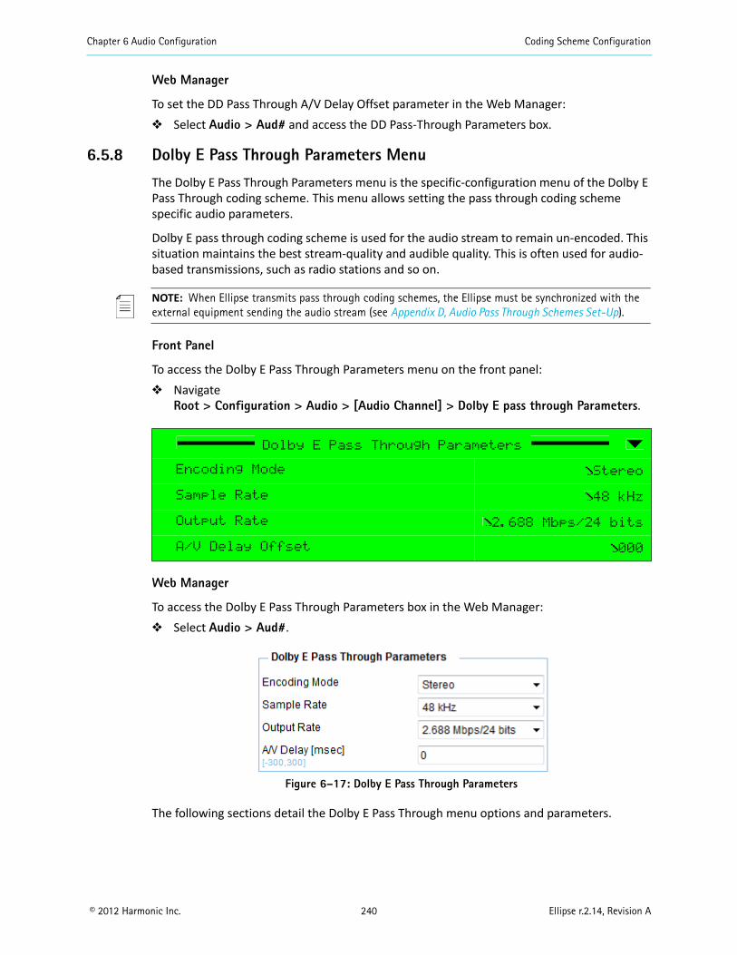
Chapter 6 Audio Configuration Coding Scheme Configuration
© 2012 Harmonic Inc. 240 Ellipse r.2.14, Revision A
Web Manager
To set the DD Pass Through A/V Delay Offset parameter in the Web Manager: Select Audio > Aud# and access the DD Pass-Through Parameters box.
6.5.8 Dolby E Pass Through Parameters Menu
The Dolby E Pass Through Parameters menu is the specific-configuration menu of the Dolby E Pass Through coding scheme. This menu allows setting the pass through coding scheme specific audio parameters.
Dolby E pass through coding scheme is used for the audio stream to remain un-encoded. This situation maintains the best stream-quality and audible quality. This is often used for audio-based transmissions, such as radio stations and so on.
NOTE: When Ellipse transmits pass through coding schemes, the Ellipse must be synchronized with the external equipment sending the audio stream (see Appendix D, Audio Pass Through Schemes Set-Up).
Front Panel
To access the Dolby E Pass Through Parameters menu on the front panel: Navigate
Root > Configuration > Audio > [Audio Channel] > Dolby E pass through Parameters.
Web Manager
To access the Dolby E Pass Through Parameters box in the Web Manager: Select Audio > Aud#.
Figure 6–17: Dolby E Pass Through Parameters
The following sections detail the Dolby E Pass Through menu options and parameters.
Dolby E Pass Through Parameters
Encoding Mode Stereo
Sample Rate 48 kHz
Output Rate 2.688 Mbps/24 bits
A/V Delay Offset 000
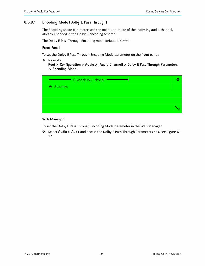
Chapter 6 Audio Configuration Coding Scheme Configuration
© 2012 Harmonic Inc. 241 Ellipse r.2.14, Revision A
6.5.8.1 Encoding Mode (Dolby E Pass Through)
The Encoding Mode parameter sets the operation mode of the incoming audio channel, already encoded in the Dolby E encoding scheme.
The Dolby E Pass Through Encoding mode default is Stereo.
Front Panel
To set the Dolby E Pass Through Encoding Mode parameter on the front panel: Navigate
Root > Configuration > Audio > [Audio Channel] > Dolby E Pass Through Parameters > Encoding Mode.
Web Manager
To set the Dolby E Pass Through Encoding Mode parameter in the Web Manager: Select Audio > Aud# and access the Dolby E Pass Through Parameters box, see Figure 6–
17.
Encoding Mode
ƒ Stereo
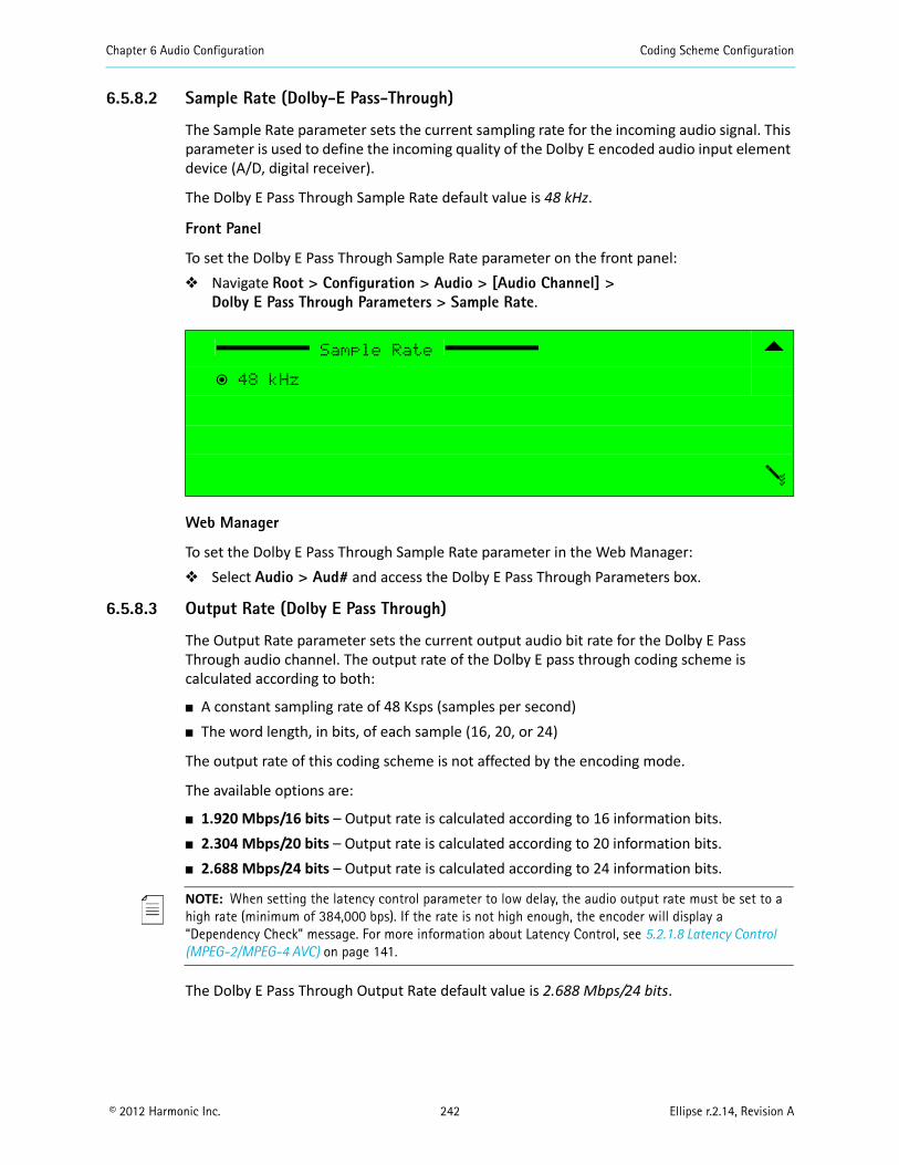
Chapter 6 Audio Configuration Coding Scheme Configuration
© 2012 Harmonic Inc. 242 Ellipse r.2.14, Revision A
6.5.8.2 Sample Rate (Dolby-E Pass-Through)
The Sample Rate parameter sets the current sampling rate for the incoming audio signal. This parameter is used to define the incoming quality of the Dolby E encoded audio input element device (A/D, digital receiver).
The Dolby E Pass Through Sample Rate default value is 48 kHz.
Front Panel
To set the Dolby E Pass Through Sample Rate parameter on the front panel: Navigate Root > Configuration > Audio > [Audio Channel] >
Dolby E Pass Through Parameters > Sample Rate.
Web Manager
To set the Dolby E Pass Through Sample Rate parameter in the Web Manager: Select Audio > Aud# and access the Dolby E Pass Through Parameters box.
6.5.8.3 Output Rate (Dolby E Pass Through)
The Output Rate parameter sets the current output audio bit rate for the Dolby E Pass Through audio channel. The output rate of the Dolby E pass through coding scheme is calculated according to both:
A constant sampling rate of 48 Ksps (samples per second) The word length, in bits, of each sample (16, 20, or 24)
The output rate of this coding scheme is not affected by the encoding mode.
The available options are:
1.920 Mbps/16 bits – Output rate is calculated according to 16 information bits. 2.304 Mbps/20 bits – Output rate is calculated according to 20 information bits. 2.688 Mbps/24 bits – Output rate is calculated according to 24 information bits.
NOTE: When setting the latency control parameter to low delay, the audio output rate must be set to a high rate (minimum of 384,000 bps). If the rate is not high enough, the encoder will display a “Dependency Check” message. For more information about Latency Control, see 5.2.1.8 Latency Control (MPEG-2/MPEG-4 AVC) on page 141.
The Dolby E Pass Through Output Rate default value is 2.688 Mbps/24 bits.
Sample Rate
ƒ 48 kHz
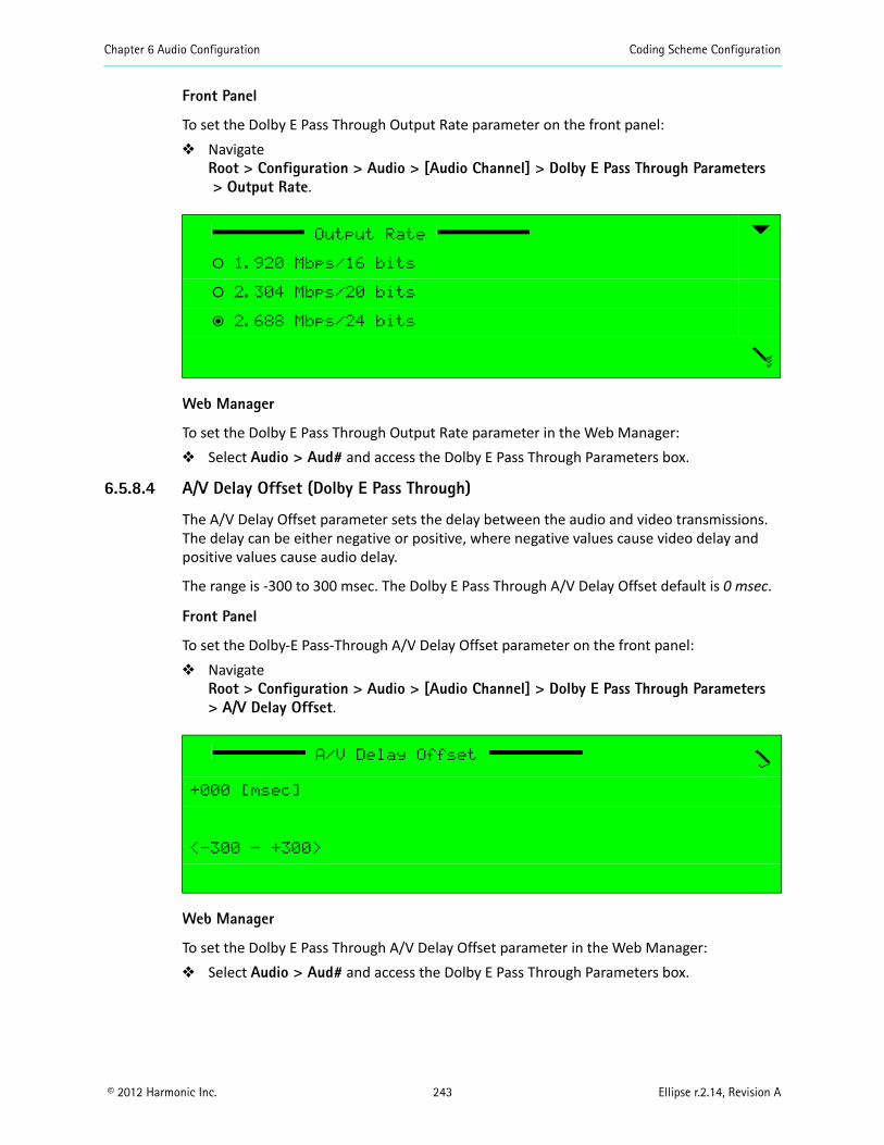
Chapter 6 Audio Configuration Coding Scheme Configuration
© 2012 Harmonic Inc. 243 Ellipse r.2.14, Revision A
Front Panel
To set the Dolby E Pass Through Output Rate parameter on the front panel: Navigate
Root > Configuration > Audio > [Audio Channel] > Dolby E Pass Through Parameters > Output Rate.
Web Manager
To set the Dolby E Pass Through Output Rate parameter in the Web Manager: Select Audio > Aud# and access the Dolby E Pass Through Parameters box.
6.5.8.4 A/V Delay Offset (Dolby E Pass Through)
The A/V Delay Offset parameter sets the delay between the audio and video transmissions. The delay can be either negative or positive, where negative values cause video delay and positive values cause audio delay.
The range is -300 to 300 msec. The Dolby E Pass Through A/V Delay Offset default is 0 msec.
Front Panel
To set the Dolby-E Pass-Through A/V Delay Offset parameter on the front panel: Navigate
Root > Configuration > Audio > [Audio Channel] > Dolby E Pass Through Parameters > A/V Delay Offset.
Web Manager
To set the Dolby E Pass Through A/V Delay Offset parameter in the Web Manager: Select Audio > Aud# and access the Dolby E Pass Through Parameters box.
Output Rate
‚ 1.920 Mbps/16 bits
‚ 2.304 Mbps/20 bits
ƒ 2.688 Mbps/24 bits
A/V Delay Offset
+000 [msec]
<-300 - +300>
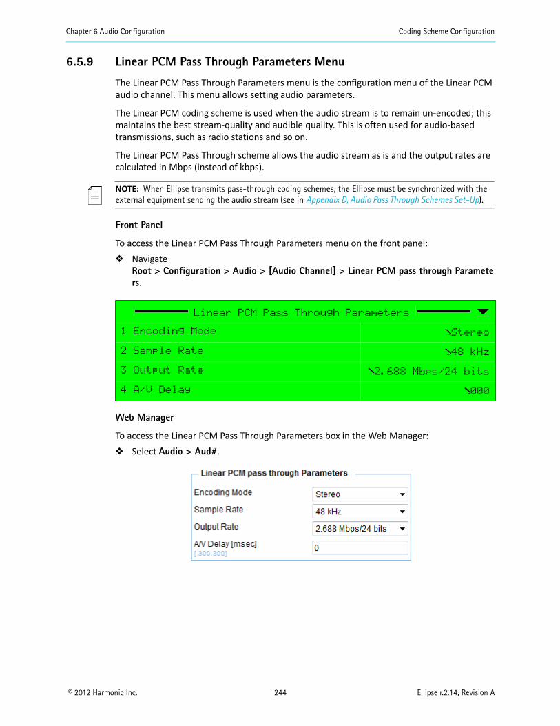
Chapter 6 Audio Configuration Coding Scheme Configuration
© 2012 Harmonic Inc. 244 Ellipse r.2.14, Revision A
6.5.9 Linear PCM Pass Through Parameters Menu
The Linear PCM Pass Through Parameters menu is the configuration menu of the Linear PCM audio channel. This menu allows setting audio parameters.
The Linear PCM coding scheme is used when the audio stream is to remain un-encoded; this maintains the best stream-quality and audible quality. This is often used for audio-based transmissions, such as radio stations and so on.
The Linear PCM Pass Through scheme allows the audio stream as is and the output rates are calculated in Mbps (instead of kbps).
NOTE: When Ellipse transmits pass-through coding schemes, the Ellipse must be synchronized with the external equipment sending the audio stream (see in Appendix D, Audio Pass Through Schemes Set-Up).
Front Panel
To access the Linear PCM Pass Through Parameters menu on the front panel: Navigate
Root > Configuration > Audio > [Audio Channel] > Linear PCM pass through Parameters.
Web Manager
To access the Linear PCM Pass Through Parameters box in the Web Manager: Select Audio > Aud#.
Linear PCM Pass Through Parameters
1 Encoding Mode Stereo
2 Sample Rate 48 kHz
3 Output Rate 2.688 Mbps/24 bits
4 A/V Delay 000
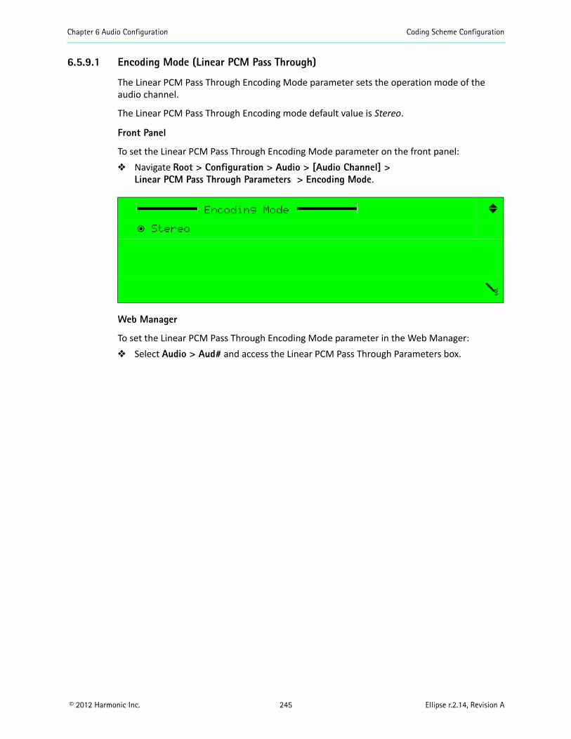
Chapter 6 Audio Configuration Coding Scheme Configuration
© 2012 Harmonic Inc. 245 Ellipse r.2.14, Revision A
6.5.9.1 Encoding Mode (Linear PCM Pass Through)
The Linear PCM Pass Through Encoding Mode parameter sets the operation mode of the audio channel.
The Linear PCM Pass Through Encoding mode default value is Stereo.
Front Panel
To set the Linear PCM Pass Through Encoding Mode parameter on the front panel: Navigate Root > Configuration > Audio > [Audio Channel] >
Linear PCM Pass Through Parameters > Encoding Mode.
Web Manager
To set the Linear PCM Pass Through Encoding Mode parameter in the Web Manager: Select Audio > Aud# and access the Linear PCM Pass Through Parameters box.
Encoding Mode
ƒ Stereo

Chapter 6 Audio Configuration Coding Scheme Configuration
© 2012 Harmonic Inc. 246 Ellipse r.2.14, Revision A
6.5.9.2 Sample Rate (Linear PCM Pass Through)
The Linear PCM Pass Through Sample Rate parameter sets the current sampling rate for the incoming audio signal. This parameter is used to define the incoming audio quality of the audio input element device (A/D, digital receiver).
The Linear PCM Pass Through Sample Rate default value is 48 kHz.
Front Panel
To set the Linear PCM Pass Through Sample Rate parameter on the front panel: Navigate Root > Configuration > Audio > [AudioChannel] >
Linear PCM Pass Through Parameters > Sample Rate.
Web Manager
To set the Linear PCM Pass Through Sample Rate parameter in the Web Manager: Select Audio > Aud# and access the Linear PCM Pass Through Parameters box.
6.5.9.3 Output Rate (Linear PCM Pass Through)
The Linear PCM Pass Through Output Rate parameter sets the current output audio bit rate for the Linear PCM audio channel. The output rate of the Linear PCM coding scheme is calculated according to both:
A constant sampling rate of 48 Ksps (samples per second) The word length, in bits, of each sample (16, 20, or 24 bits)
The output rate of this coding scheme is not affected by its encoding mode.
The available options are:
1.920 Mbps/16 bits – Output rate is calculated according to 16 information bits. 2.304 Mbps/20 bits – Output rate is calculated according to 20 information bits. 2.688 Mbps/24 bits – Output rate is calculated according to 24 information bits.
The Linear PCM Pass Through Output Rate default value is 2.688 Mbps/24 bits.
Sample Rate
ƒ 48 kHz
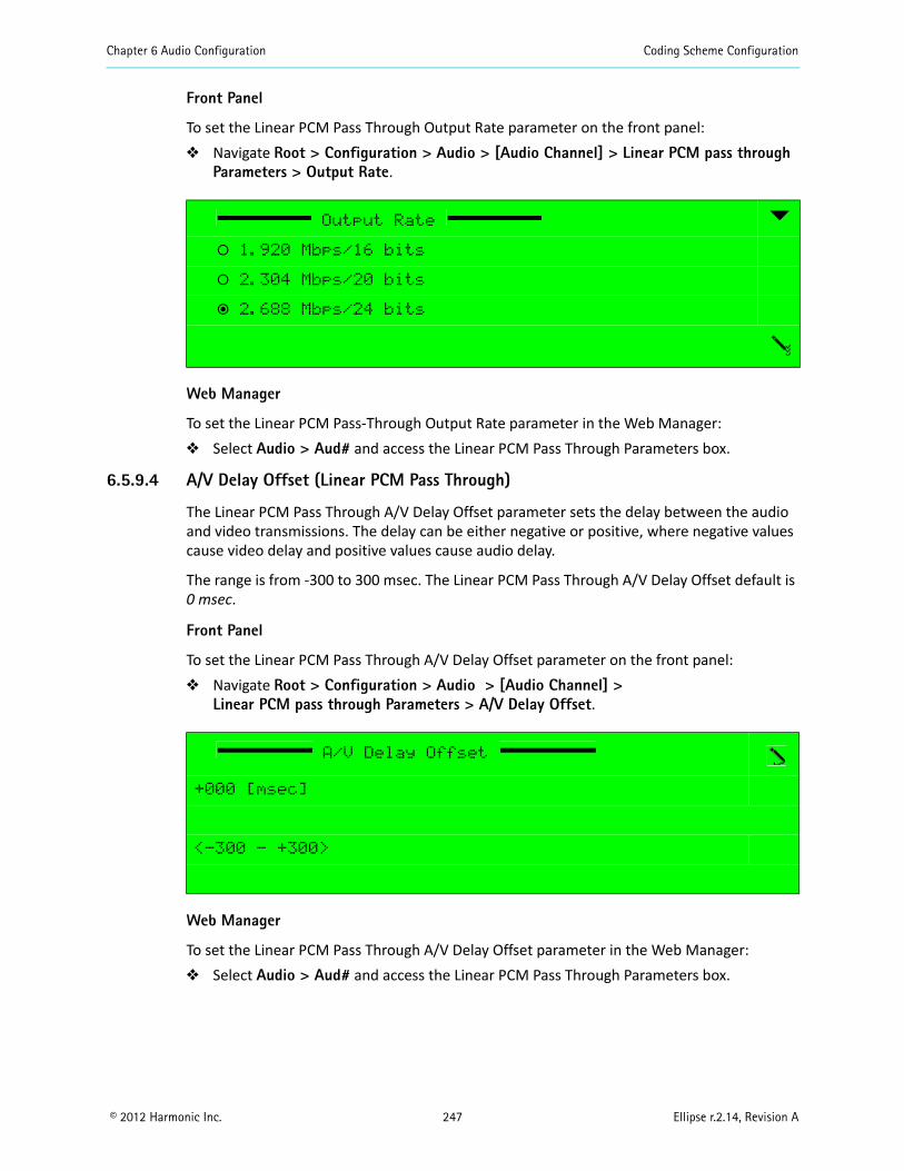
Chapter 6 Audio Configuration Coding Scheme Configuration
© 2012 Harmonic Inc. 247 Ellipse r.2.14, Revision A
Front Panel
To set the Linear PCM Pass Through Output Rate parameter on the front panel: Navigate Root > Configuration > Audio > [Audio Channel] > Linear PCM pass through
Parameters > Output Rate.
Web Manager
To set the Linear PCM Pass-Through Output Rate parameter in the Web Manager: Select Audio > Aud# and access the Linear PCM Pass Through Parameters box.
6.5.9.4 A/V Delay Offset (Linear PCM Pass Through)
The Linear PCM Pass Through A/V Delay Offset parameter sets the delay between the audio and video transmissions. The delay can be either negative or positive, where negative values cause video delay and positive values cause audio delay.
The range is from -300 to 300 msec. The Linear PCM Pass Through A/V Delay Offset default is 0 msec.
Front Panel
To set the Linear PCM Pass Through A/V Delay Offset parameter on the front panel: Navigate Root > Configuration > Audio > [Audio Channel] >
Linear PCM pass through Parameters > A/V Delay Offset.
Web Manager
To set the Linear PCM Pass Through A/V Delay Offset parameter in the Web Manager: Select Audio > Aud# and access the Linear PCM Pass Through Parameters box.
Output Rate
‚ 1.920 Mbps/16 bits
‚ 2.304 Mbps/20 bits
ƒ 2.688 Mbps/24 bits
A/V Delay Offset
+000 [msec]
<-300 - +300>
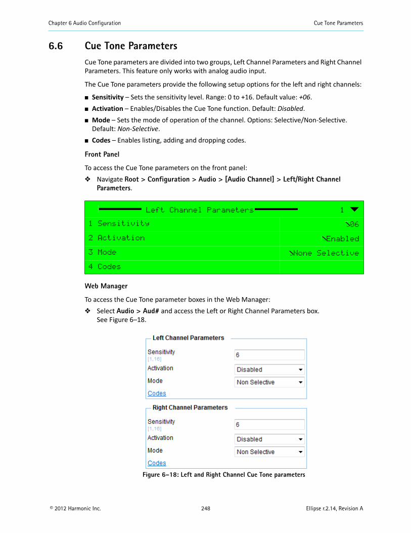
Chapter 6 Audio Configuration Cue Tone Parameters
© 2012 Harmonic Inc. 248 Ellipse r.2.14, Revision A
6.6 Cue Tone ParametersCue Tone parameters are divided into two groups, Left Channel Parameters and Right Channel Parameters. This feature only works with analog audio input.
The Cue Tone parameters provide the following setup options for the left and right channels:
Sensitivity – Sets the sensitivity level. Range: 0 to +16. Default value: +06. Activation – Enables/Disables the Cue Tone function. Default: Disabled. Mode – Sets the mode of operation of the channel. Options: Selective/Non-Selective.
Default: Non-Selective. Codes – Enables listing, adding and dropping codes.
Front Panel
To access the Cue Tone parameters on the front panel: Navigate Root > Configuration > Audio > [Audio Channel] > Left/Right Channel
Parameters.
Web Manager
To access the Cue Tone parameter boxes in the Web Manager: Select Audio > Aud# and access the Left or Right Channel Parameters box.
See Figure 6–18.
Figure 6–18: Left and Right Channel Cue Tone parameters
Left Channel Parameters 1
1 Sensitivity 06
2 Activation Enabled
3 Mode None Selective
4 Codes
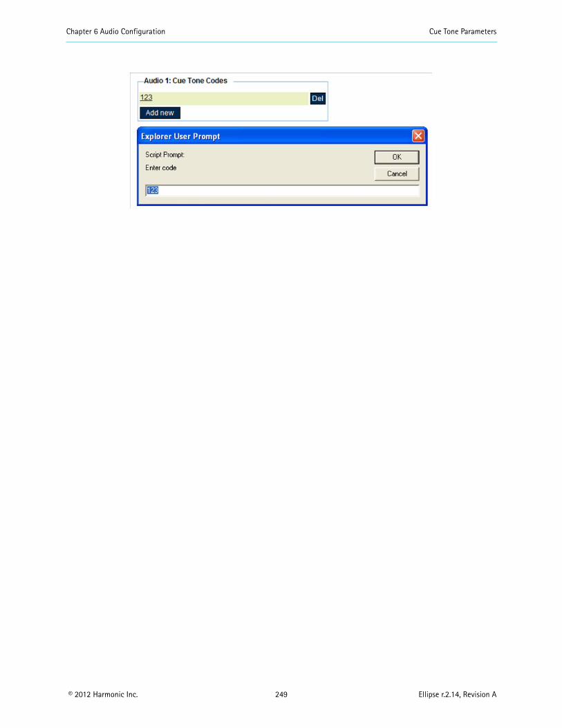
Chapter 6 Audio Configuration Cue Tone Parameters
© 2012 Harmonic Inc. 249 Ellipse r.2.14, Revision A
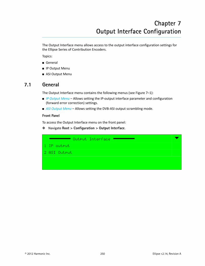
© 2012 Harmonic Inc. 250 Ellipse r.2.14, Revision A
Chapter 7Output Interface Configuration
The Output Interface menu allows access to the output interface configuration settings for the Ellipse Series of Contribution Encoders.
Topics:
General IP Output Menu ASI Output Menu
7.1 GeneralThe Output Interface menu contains the following menus (see Figure 7–1): IP Output Menu – Allows setting the IP-output interface parameter and configuration
(forward error correction) settings. ASI Output Menu – Allows setting the DVB-ASI output scrambling mode.
Front Panel
To access the Output Interface menu on the front panel: Navigate Root > Configuration > Output Interface.
Output Interface
1 IP output
2 ASI Output
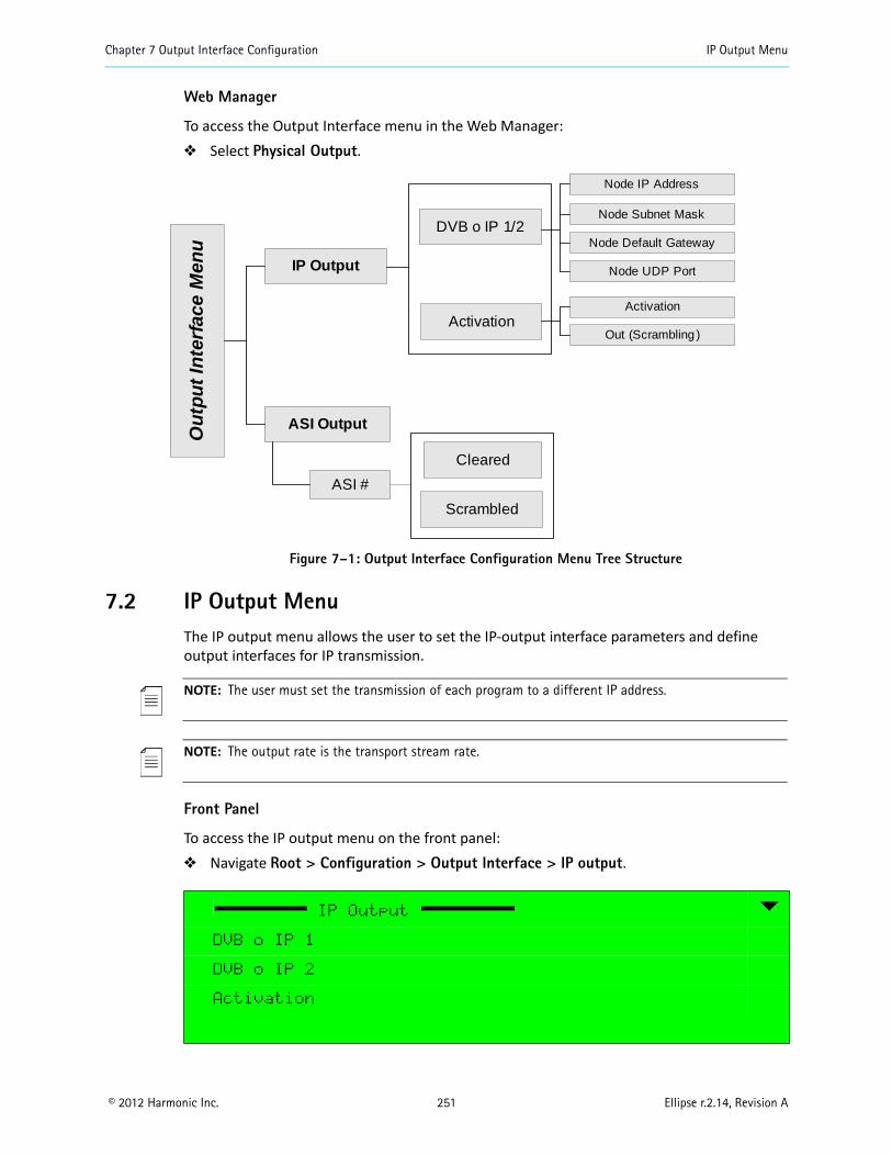
Chapter 7 Output Interface Configuration IP Output Menu
© 2012 Harmonic Inc. 251 Ellipse r.2.14, Revision A
Web Manager
To access the Output Interface menu in the Web Manager: Select Physical Output.
Figure 7–1: Output Interface Configuration Menu Tree Structure
7.2 IP Output MenuThe IP output menu allows the user to set the IP-output interface parameters and define output interfaces for IP transmission.
NOTE: The user must set the transmission of each program to a different IP address.
NOTE: The output rate is the transport stream rate.
Front Panel
To access the IP output menu on the front panel: Navigate Root > Configuration > Output Interface > IP output.
IP Output
DVB o IP 1
DVB o IP 2
Activation
ASI Output
Cleared
IP Output
DVB o IP 1/2
Activation
Ou
tpu
t In
terf
ace
Men
u
Scrambled
Node Subnet Mask
Node Default Gateway
Node UDP Port
Activation
Out (Scrambling )
Node IP Address
ASI #
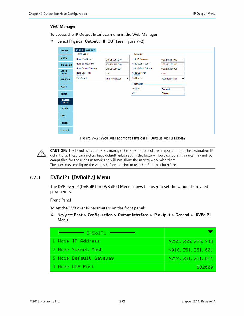
Chapter 7 Output Interface Configuration IP Output Menu
© 2012 Harmonic Inc. 252 Ellipse r.2.14, Revision A
Web Manager
To access the IP-Output Interface menu in the Web Manager: Select Physical Output > IP OUT (see Figure 7–2).
Figure 7–2: Web Management Physical IP Output Menu Display
CAUTION: The IP output parameters manage the IP definitions of the Ellipse unit and the destination IP definitions. These parameters have default values set in the factory. However, default values may not be compatible for the user’s network and will not allow the user to work with them.The user must configure the values before starting to use the IP output interface.
7.2.1 DVBoIP1 (DVBoIP2) Menu
The DVB over IP (DVBoIP1 or DVBoIP2) Menu allows the user to set the various IP related parameters.
Front Panel
To set the DVB over IP parameters on the front panel: Navigate Root > Configuration > Output Interface > IP output > General > DVBoIP1
Menu.
DVBoIP1
1 Node IP Address 255.255.255.240
2 Node Subnet Mask 010.251.251.001
3 Node Default Gateway 224.251.251.001
4 Node UDP Port 02000
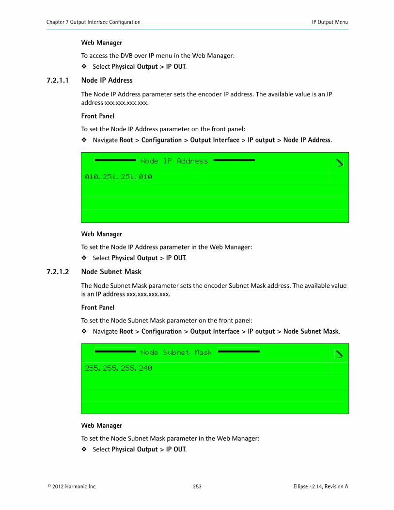
Chapter 7 Output Interface Configuration IP Output Menu
© 2012 Harmonic Inc. 253 Ellipse r.2.14, Revision A
Web Manager
To access the DVB over IP menu in the Web Manager: Select Physical Output > IP OUT.
7.2.1.1 Node IP Address
The Node IP Address parameter sets the encoder IP address. The available value is an IP address xxx.xxx.xxx.xxx.
Front Panel
To set the Node IP Address parameter on the front panel: Navigate Root > Configuration > Output Interface > IP output > Node IP Address.
Web Manager
To set the Node IP Address parameter in the Web Manager: Select Physical Output > IP OUT.
7.2.1.2 Node Subnet Mask
The Node Subnet Mask parameter sets the encoder Subnet Mask address. The available value is an IP address xxx.xxx.xxx.xxx.
Front Panel
To set the Node Subnet Mask parameter on the front panel: Navigate Root > Configuration > Output Interface > IP output > Node Subnet Mask.
Web Manager
To set the Node Subnet Mask parameter in the Web Manager: Select Physical Output > IP OUT.
Node IP Address
010.251.251.010
Node Subnet Mask
255.255.255.240
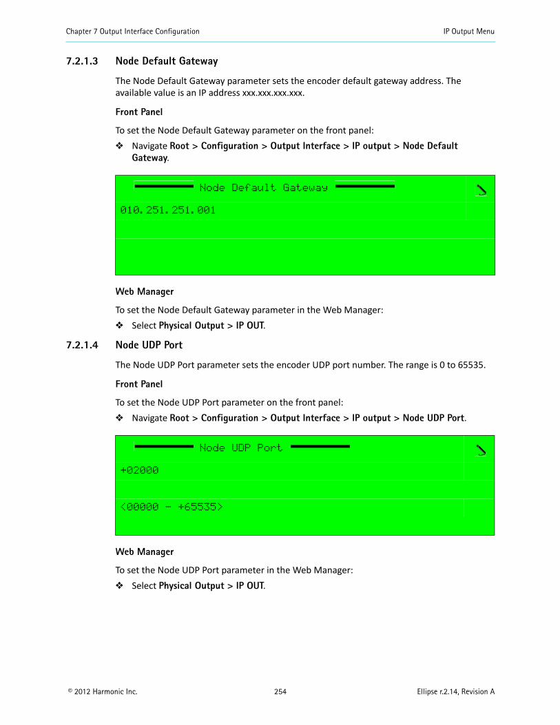
Chapter 7 Output Interface Configuration IP Output Menu
© 2012 Harmonic Inc. 254 Ellipse r.2.14, Revision A
7.2.1.3 Node Default Gateway
The Node Default Gateway parameter sets the encoder default gateway address. The available value is an IP address xxx.xxx.xxx.xxx.
Front Panel
To set the Node Default Gateway parameter on the front panel: Navigate Root > Configuration > Output Interface > IP output > Node Default
Gateway.
Web Manager
To set the Node Default Gateway parameter in the Web Manager: Select Physical Output > IP OUT.
7.2.1.4 Node UDP Port
The Node UDP Port parameter sets the encoder UDP port number. The range is 0 to 65535.
Front Panel
To set the Node UDP Port parameter on the front panel: Navigate Root > Configuration > Output Interface > IP output > Node UDP Port.
Web Manager
To set the Node UDP Port parameter in the Web Manager: Select Physical Output > IP OUT.
Node Default Gateway
010.251.251.001
Node UDP Port
+02000
<00000 - +65535>
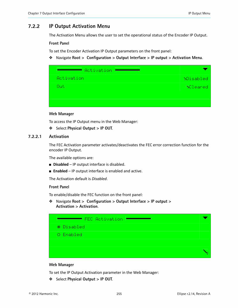
Chapter 7 Output Interface Configuration IP Output Menu
© 2012 Harmonic Inc. 255 Ellipse r.2.14, Revision A
7.2.2 IP Output Activation Menu
The Activation Menu allows the user to set the operational status of the Encoder IP Output.
Front Panel
To set the Encoder Activation IP Output parameters on the front panel: Navigate Root > Configuration > Output Interface > IP output > Activation Menu.
Web Manager
To access the IP Output menu in the Web Manager: Select Physical Output > IP OUT.
7.2.2.1 Activation
The FEC Activation parameter activates/deactivates the FEC error correction function for the encoder IP Output.
The available options are: Disabled – IP output interface is disabled. Enabled – IP output interface is enabled and active.
The Activation default is Disabled.
Front Panel
To enable/disable the FEC function on the front panel: Navigate Root > Configuration > Output Interface > IP output >
Activation > Activation.
Web Manager
To set the IP Output Activation parameter in the Web Manager: Select Physical Output > IP OUT.
Activation
Activation Disabled
Out Cleared
FEC Activation
ƒ Disabled
‚ Enabled
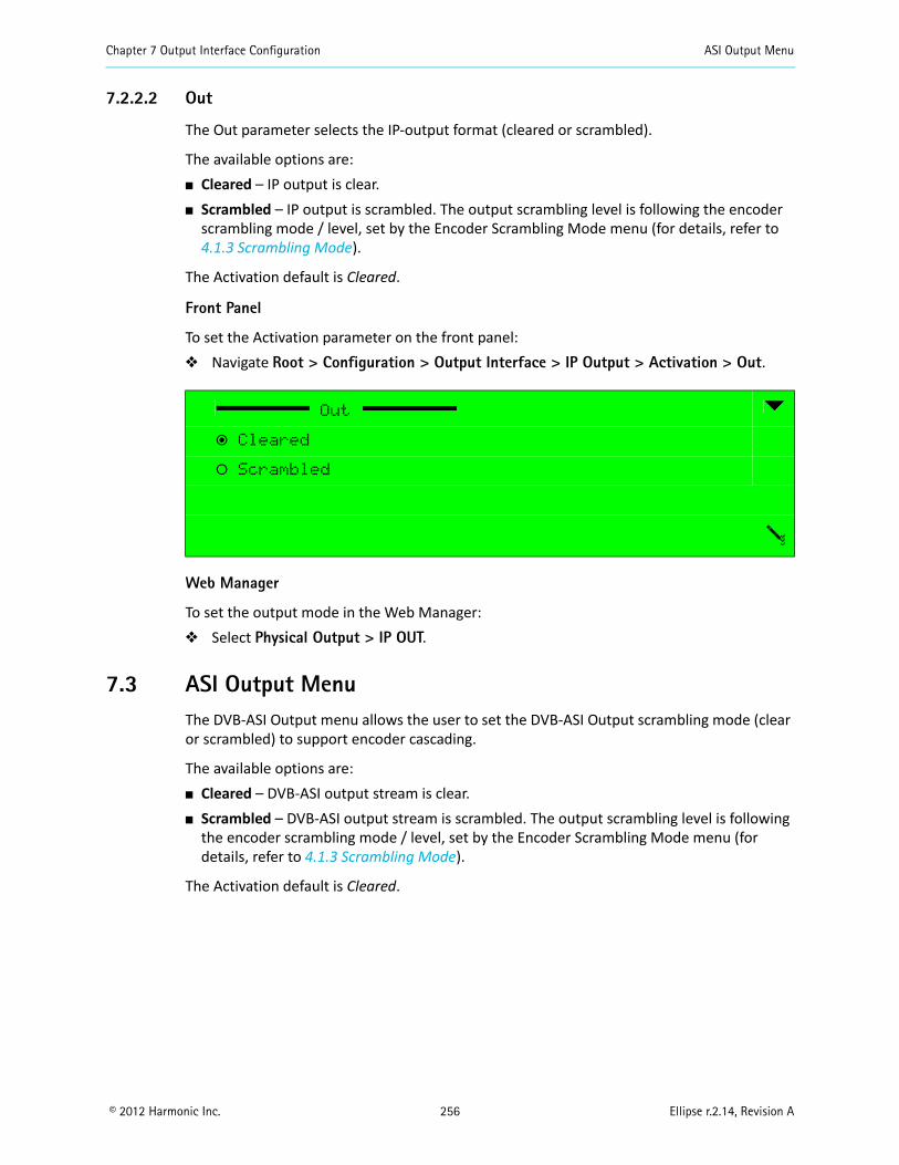
Chapter 7 Output Interface Configuration ASI Output Menu
© 2012 Harmonic Inc. 256 Ellipse r.2.14, Revision A
7.2.2.2 Out
The Out parameter selects the IP-output format (cleared or scrambled).
The available options are: Cleared – IP output is clear. Scrambled – IP output is scrambled. The output scrambling level is following the encoder
scrambling mode / level, set by the Encoder Scrambling Mode menu (for details, refer to 4.1.3 Scrambling Mode).
The Activation default is Cleared.
Front Panel
To set the Activation parameter on the front panel: Navigate Root > Configuration > Output Interface > IP Output > Activation > Out.
Web Manager
To set the output mode in the Web Manager: Select Physical Output > IP OUT.
7.3 ASI Output MenuThe DVB-ASI Output menu allows the user to set the DVB-ASI Output scrambling mode (clear or scrambled) to support encoder cascading.
The available options are: Cleared – DVB-ASI output stream is clear. Scrambled – DVB-ASI output stream is scrambled. The output scrambling level is following
the encoder scrambling mode / level, set by the Encoder Scrambling Mode menu (for details, refer to 4.1.3 Scrambling Mode).
The Activation default is Cleared.
Out
ƒ Cleared
‚ Scrambled
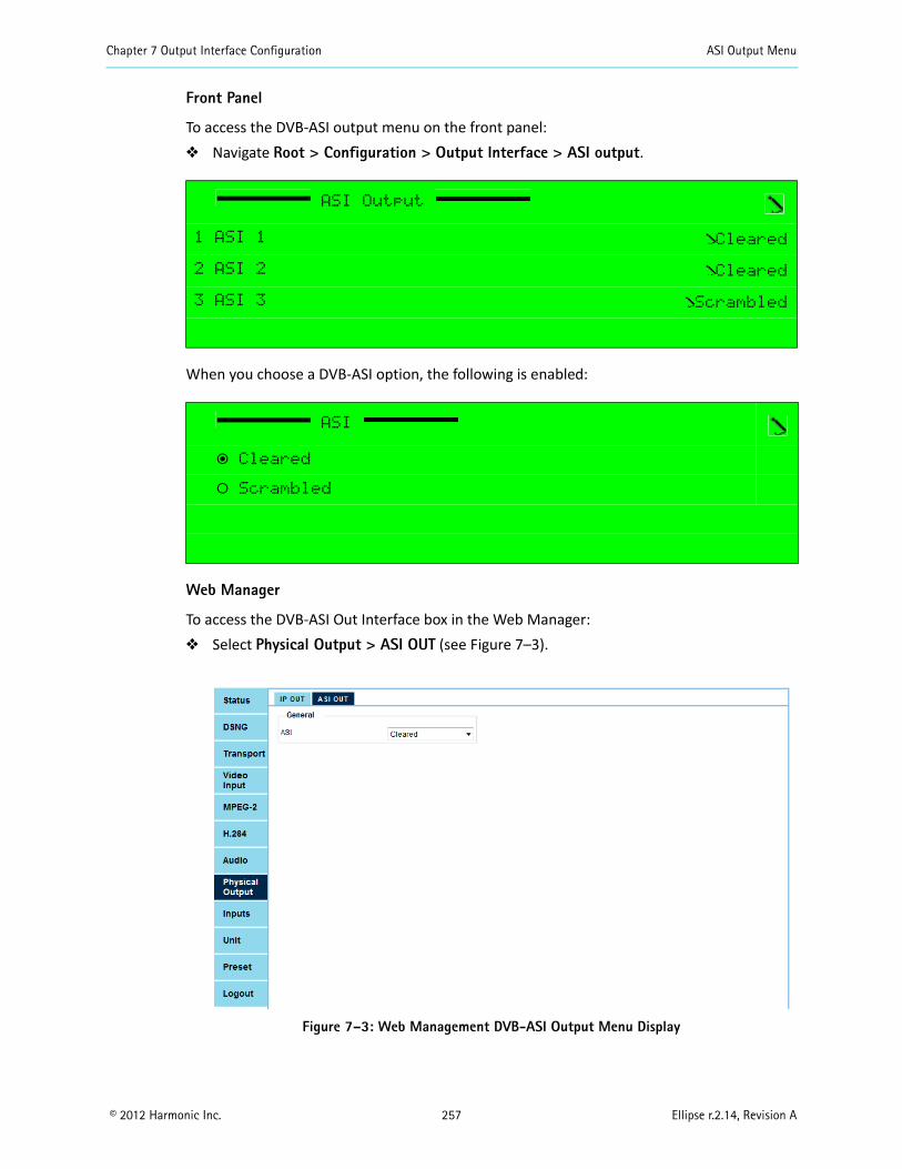
Chapter 7 Output Interface Configuration ASI Output Menu
© 2012 Harmonic Inc. 257 Ellipse r.2.14, Revision A
Front Panel
To access the DVB-ASI output menu on the front panel: Navigate Root > Configuration > Output Interface > ASI output.
When you choose a DVB-ASI option, the following is enabled:
Web Manager
To access the DVB-ASI Out Interface box in the Web Manager: Select Physical Output > ASI OUT (see Figure 7–3).
Figure 7–3: Web Management DVB-ASI Output Menu Display
ASI Output
1 ASI 1 Cleared
2 ASI 2 Cleared
3 ASI 3 Scrambled
ASI
ƒ Cleared
‚ Scrambled
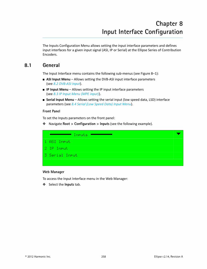
© 2012 Harmonic Inc. 258 Ellipse r.2.14, Revision A
Chapter 8Input Interface Configuration
The Inputs Configuration Menu allows setting the input interface parameters and defines input interfaces for a given input signal (ASI, IP or Serial) at the Ellipse Series of Contribution Encoders.
8.1 GeneralThe Input Interface menu contains the following sub-menus (see Figure 8–1): ASI Input Menu – Allows setting the DVB-ASI input interface parameters
(see 8.2 DVB-ASI Input). IP Input Menu – Allows setting the IP input interface parameters
(see 8.3 IP Input Menu (MPE input)). Serial Input Menu – Allows setting the serial input (low speed data, LSD) interface
parameters (see 8.4 Serial (Low Speed Data) Input Menu).
Front Panel
To set the Inputs parameters on the front panel: Navigate Root > Configuration > Inputs (see the following example).
Web Manager
To access the Input Interface menu in the Web Manager: Select the Inputs tab.
Inputs
1 ASI Input
2 IP Input
3 Serial Input
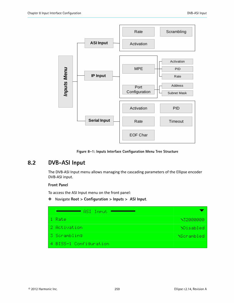
Chapter 8 Input Interface Configuration DVB-ASI Input
© 2012 Harmonic Inc. 259 Ellipse r.2.14, Revision A
Figure 8–1: Inputs Interface Configuration Menu Tree Structure
8.2 DVB-ASI InputThe DVB-ASI Input menu allows managing the cascading parameters of the Ellipse encoder DVB-ASI input.
Front Panel
To access the ASI Input menu on the front panel: Navigate Root > Configuration > Inputs > ASI Input.
ASI Input
1 Rate 32000000
2 Activation Disabled
3 Scrambling Scrambled
4 BISS-1 Configuration
ASI Input
Serial Input
Scrambling
IP Input
MPE
Port Configuration
Activation PID
Inp
uts
Men
u
Rate Timeout
EOF Char
Activation
PID
Rate
Address
Subnet Mask
Rate
Activation
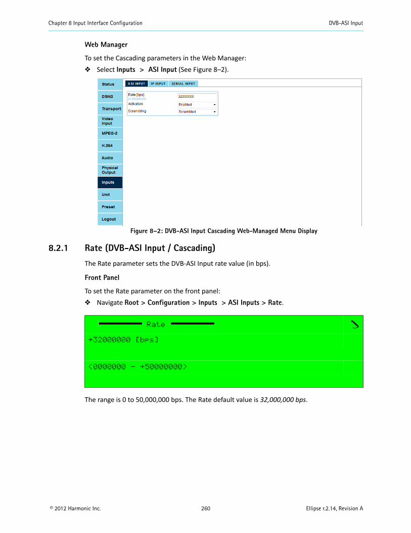
Chapter 8 Input Interface Configuration DVB-ASI Input
© 2012 Harmonic Inc. 260 Ellipse r.2.14, Revision A
Web Manager
To set the Cascading parameters in the Web Manager: Select Inputs > ASI Input (See Figure 8–2).
Figure 8–2: DVB-ASI Input Cascading Web-Managed Menu Display
8.2.1 Rate (DVB-ASI Input / Cascading)
The Rate parameter sets the DVB-ASI Input rate value (in bps).
Front Panel
To set the Rate parameter on the front panel: Navigate Root > Configuration > Inputs > ASI Inputs > Rate.
The range is 0 to 50,000,000 bps. The Rate default value is 32,000,000 bps.
Rate
+32000000 [bps]
<0000000 - +50000000>
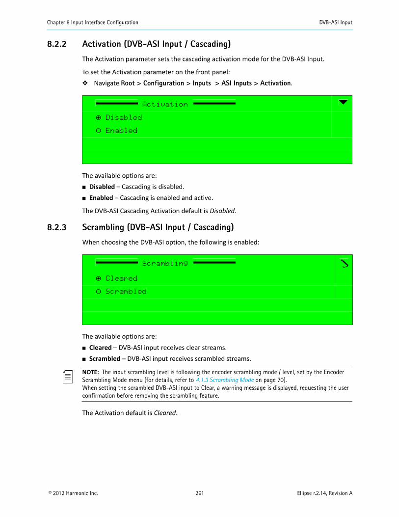
Chapter 8 Input Interface Configuration DVB-ASI Input
© 2012 Harmonic Inc. 261 Ellipse r.2.14, Revision A
8.2.2 Activation (DVB-ASI Input / Cascading)
The Activation parameter sets the cascading activation mode for the DVB-ASI Input.
To set the Activation parameter on the front panel: Navigate Root > Configuration > Inputs > ASI Inputs > Activation.
The available options are: Disabled – Cascading is disabled. Enabled – Cascading is enabled and active.
The DVB-ASI Cascading Activation default is Disabled.
8.2.3 Scrambling (DVB-ASI Input / Cascading)
When choosing the DVB-ASI option, the following is enabled:
The available options are: Cleared – DVB-ASI input receives clear streams. Scrambled – DVB-ASI input receives scrambled streams.
NOTE: The input scrambling level is following the encoder scrambling mode / level, set by the Encoder Scrambling Mode menu (for details, refer to 4.1.3 Scrambling Mode on page 70).When setting the scrambled DVB-ASI input to Clear, a warning message is displayed, requesting the user confirmation before removing the scrambling feature.
The Activation default is Cleared.
Activation
ƒ Disabled
‚ Enabled
Scrambling
ƒ Cleared
‚ Scrambled
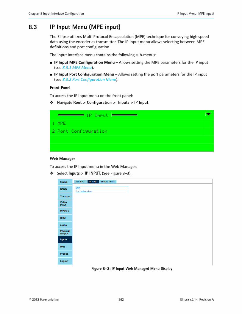
Chapter 8 Input Interface Configuration IP Input Menu (MPE input)
© 2012 Harmonic Inc. 262 Ellipse r.2.14, Revision A
8.3 IP Input Menu (MPE input)The Ellipse utilizes Multi Protocol Encapsulation (MPE) technique for conveying high speed data using the encoder as transmitter. The IP Input menu allows selecting between MPE definitions and port configuration.
The Input Interface menu contains the following sub-menus:
IP Input MPE Configuration Menu – Allows setting the MPE parameters for the IP input (see 8.3.1 MPE Menu).
IP Input Port Configuration Menu – Allows setting the port parameters for the IP input (see 8.3.2 Port Configuration Menu).
Front Panel
To access the IP Input menu on the front panel: Navigate Root > Configuration > Inputs > IP Input.
Web Manager
To access the IP Input menu in the Web Manager: Select Inputs > IP INPUT. (See Figure 8–3).
Figure 8–3: IP Input Web Managed Menu Display
IP Input
1 MPE
2 Port Configuration
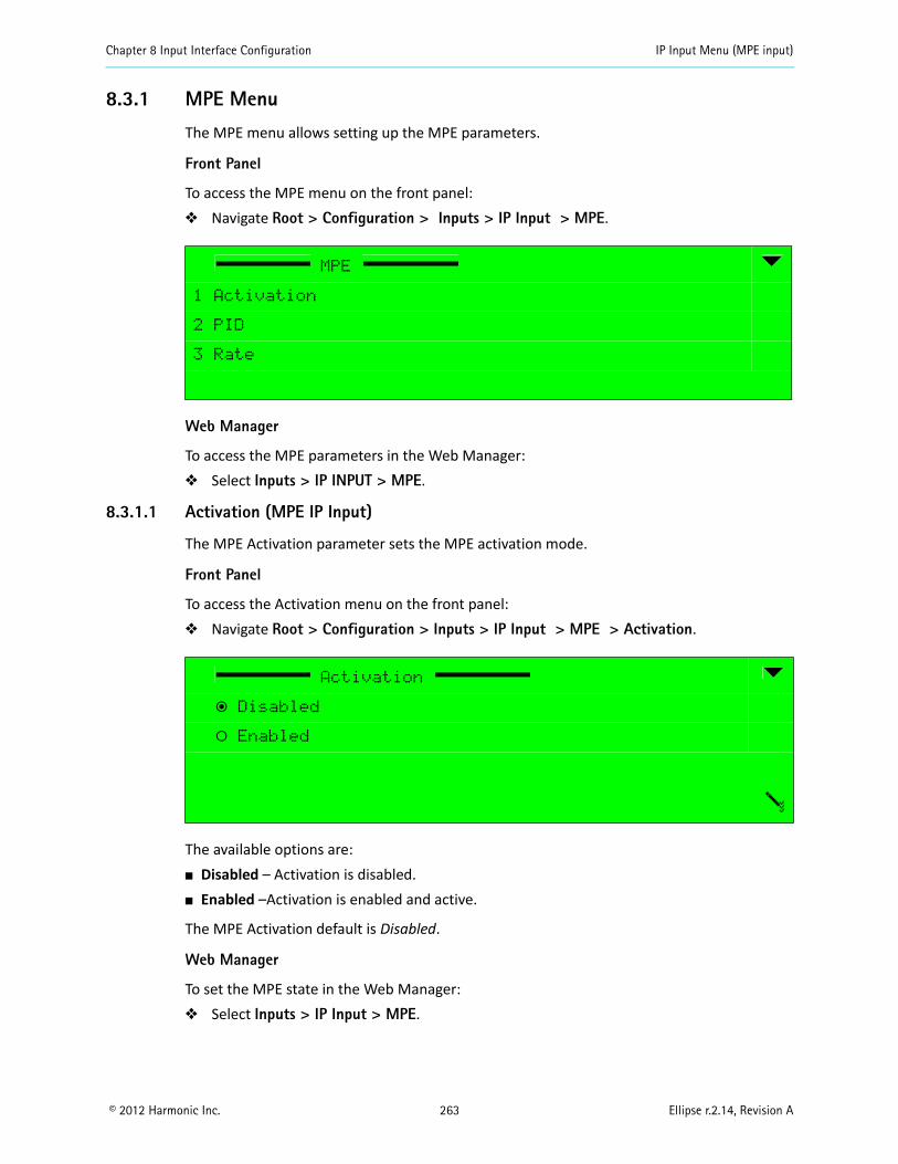
Chapter 8 Input Interface Configuration IP Input Menu (MPE input)
© 2012 Harmonic Inc. 263 Ellipse r.2.14, Revision A
8.3.1 MPE Menu
The MPE menu allows setting up the MPE parameters.
Front Panel
To access the MPE menu on the front panel: Navigate Root > Configuration > Inputs > IP Input > MPE.
Web Manager
To access the MPE parameters in the Web Manager: Select Inputs > IP INPUT > MPE.
8.3.1.1 Activation (MPE IP Input)
The MPE Activation parameter sets the MPE activation mode.
Front Panel
To access the Activation menu on the front panel: Navigate Root > Configuration > Inputs > IP Input > MPE > Activation.
The available options are: Disabled – Activation is disabled. Enabled –Activation is enabled and active.
The MPE Activation default is Disabled.
Web Manager
To set the MPE state in the Web Manager: Select Inputs > IP Input > MPE.
MPE
1 Activation
2 PID
3 Rate
Activation
ƒ Disabled
‚ Enabled
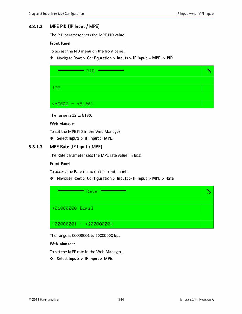
Chapter 8 Input Interface Configuration IP Input Menu (MPE input)
© 2012 Harmonic Inc. 264 Ellipse r.2.14, Revision A
8.3.1.2 MPE PID (IP Input / MPE)
The PID parameter sets the MPE PID value.
Front Panel
To access the PID menu on the front panel: Navigate Root > Configuration > Inputs > IP Input > MPE > PID.
The range is 32 to 8190.
Web Manager
To set the MPE PID in the Web Manager: Select Inputs > IP Input > MPE.
8.3.1.3 MPE Rate (IP Input / MPE)
The Rate parameter sets the MPE rate value (in bps).
Front Panel
To access the Rate menu on the front panel: Navigate Root > Configuration > Inputs > IP Input > MPE > Rate.
The range is 00000001 to 20000000 bps.
Web Manager
To set the MPE rate in the Web Manager: Select Inputs > IP Input > MPE.
PID
138
<+0032 - +8190>
Rate
+01000000 [bps]
<00000001 - +20000000>
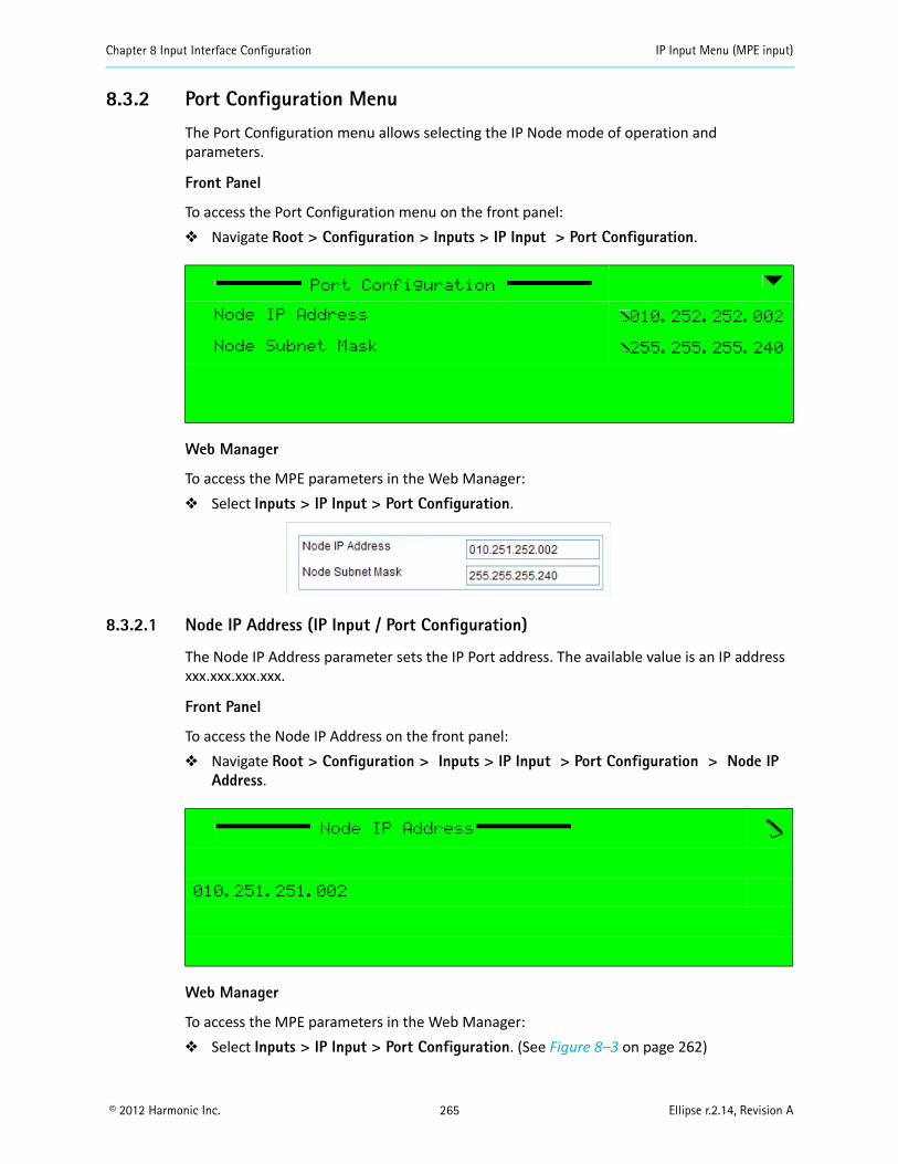
Chapter 8 Input Interface Configuration IP Input Menu (MPE input)
© 2012 Harmonic Inc. 265 Ellipse r.2.14, Revision A
8.3.2 Port Configuration Menu
The Port Configuration menu allows selecting the IP Node mode of operation and parameters.
Front Panel
To access the Port Configuration menu on the front panel: Navigate Root > Configuration > Inputs > IP Input > Port Configuration.
Web Manager
To access the MPE parameters in the Web Manager: Select Inputs > IP Input > Port Configuration.
8.3.2.1 Node IP Address (IP Input / Port Configuration)
The Node IP Address parameter sets the IP Port address. The available value is an IP address xxx.xxx.xxx.xxx.
Front Panel
To access the Node IP Address on the front panel: Navigate Root > Configuration > Inputs > IP Input > Port Configuration > Node IP
Address.
Web Manager
To access the MPE parameters in the Web Manager: Select Inputs > IP Input > Port Configuration. (See Figure 8–3 on page 262)
Port Configuration
Node IP Address 010.252.252.002
Node Subnet Mask 255.255.255.240
Node IP Address
010.251.251.002
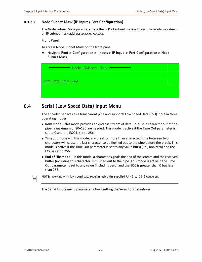
Chapter 8 Input Interface Configuration Serial (Low Speed Data) Input Menu
© 2012 Harmonic Inc. 266 Ellipse r.2.14, Revision A
8.3.2.2 Node Subnet Mask (IP Input / Port Configuration)
The Node Subnet Mask parameter sets the IP Port subnet mask address. The available value is an IP subnet mask address xxx.xxx.xxx.xxx.
Front Panel
To access Node Subnet Mask on the front panel: Navigate Root > Configuration > Inputs > IP Input > Port Configuration > Node
Subnet Mask.
8.4 Serial (Low Speed Data) Input MenuThe Encoder behaves as a transparent pipe and supports Low Speed Data (LSD) input in three operating modes: Row mode – this mode provides an endless stream of data. To push a character out of the
pipe, a maximum of 80+180 are needed. This mode is active if the Time Out parameter is set to 0 and the EOC is set to 256.
Timeout mode – in this mode, any break of more than a selected time between two characters will cause the last character to be flushed out to the pipe before the break. This mode is active if the Time Out parameter is set to any value but 0 (i.e., non zero) and the EOC is set to 256.
End of File mode – in this mode, a character signals the end of the stream and the received buffer (including this character) is flushed out to the pipe. This mode is active if the Time Out parameter is set to any value (including zero) and the EOC is greater than 0 but less than 256.
NOTE: Working with low speed data requires using the supplied RJ-45-to-DB-9 converter.
The Serial Inputs menu parameter allows setting the Serial LSD definitions.
Node Subnet Mask
255.255.255.240

Chapter 8 Input Interface Configuration Serial (Low Speed Data) Input Menu
© 2012 Harmonic Inc. 267 Ellipse r.2.14, Revision A
Front Panel
To access the Serial Input sub-menu on the front panel: Navigate Root > Configuration > Inputs > Serial Input > LSD.
Web Manager
To access the Serial Inputs LSD set-up menu in the Web Manager: Select Inputs > SERIAL INPUT > LSD (See Figure 8–4).
Figure 8–4: Serial Inputs LSD Web Managed Menu Display
LSD
Activation
PID
Rate
Timeout
EOF Char
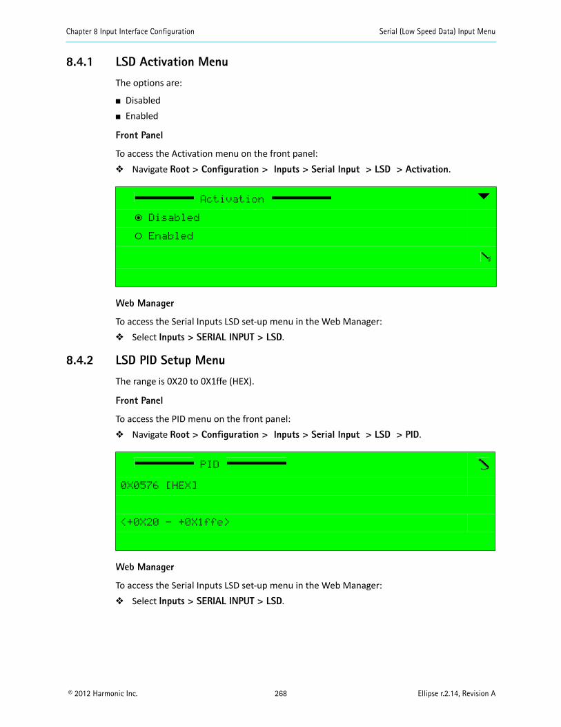
Chapter 8 Input Interface Configuration Serial (Low Speed Data) Input Menu
© 2012 Harmonic Inc. 268 Ellipse r.2.14, Revision A
8.4.1 LSD Activation Menu
The options are:
Disabled Enabled
Front Panel
To access the Activation menu on the front panel: Navigate Root > Configuration > Inputs > Serial Input > LSD > Activation.
Web Manager
To access the Serial Inputs LSD set-up menu in the Web Manager: Select Inputs > SERIAL INPUT > LSD.
8.4.2 LSD PID Setup Menu
The range is 0X20 to 0X1ffe (HEX).
Front Panel
To access the PID menu on the front panel: Navigate Root > Configuration > Inputs > Serial Input > LSD > PID.
Web Manager
To access the Serial Inputs LSD set-up menu in the Web Manager: Select Inputs > SERIAL INPUT > LSD.
Activation
ƒ Disabled
‚ Enabled
PID
0X0576 [HEX]
<+0X20 - +0X1ffe>
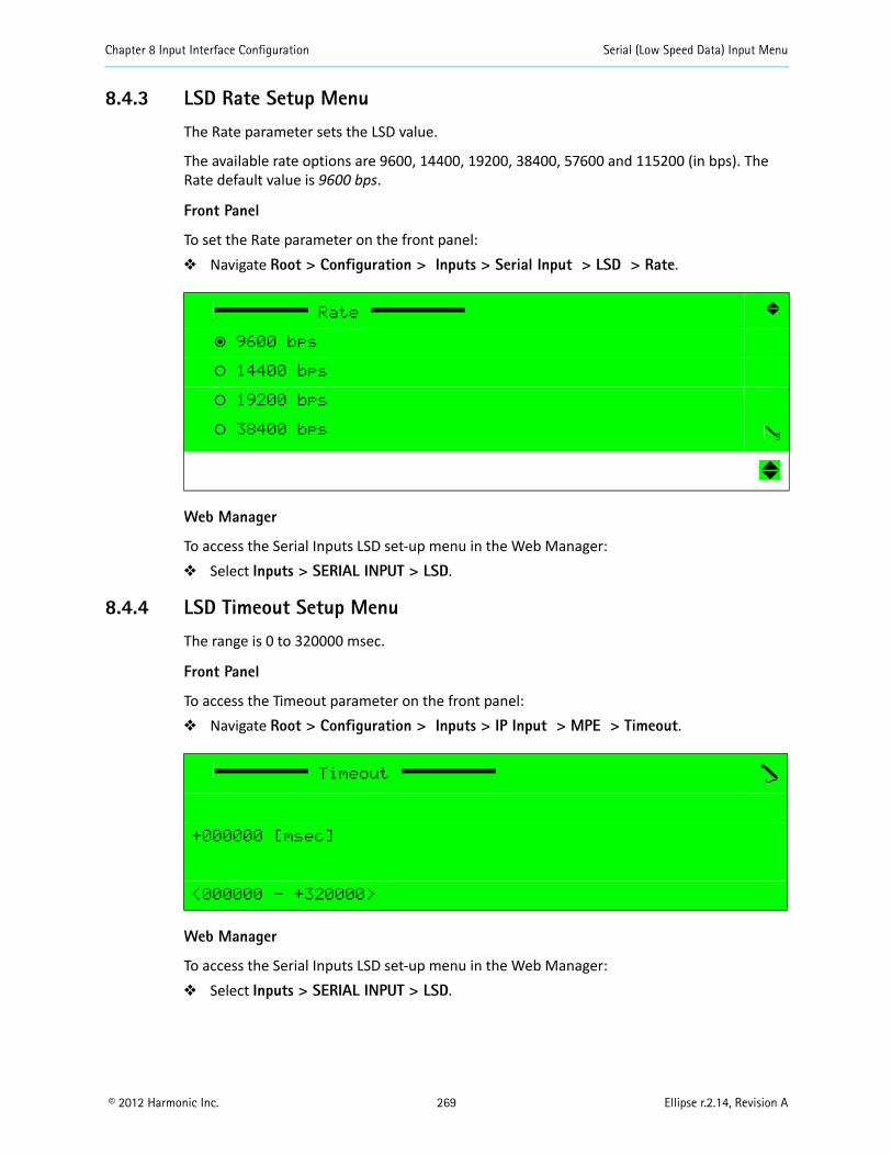
Chapter 8 Input Interface Configuration Serial (Low Speed Data) Input Menu
© 2012 Harmonic Inc. 269 Ellipse r.2.14, Revision A
8.4.3 LSD Rate Setup Menu
The Rate parameter sets the LSD value.
The available rate options are 9600, 14400, 19200, 38400, 57600 and 115200 (in bps). The Rate default value is 9600 bps.
Front Panel
To set the Rate parameter on the front panel: Navigate Root > Configuration > Inputs > Serial Input > LSD > Rate.
Web Manager
To access the Serial Inputs LSD set-up menu in the Web Manager: Select Inputs > SERIAL INPUT > LSD.
8.4.4 LSD Timeout Setup Menu
The range is 0 to 320000 msec.
Front Panel
To access the Timeout parameter on the front panel: Navigate Root > Configuration > Inputs > IP Input > MPE > Timeout.
Web Manager
To access the Serial Inputs LSD set-up menu in the Web Manager: Select Inputs > SERIAL INPUT > LSD.
Rate
ƒ 9600 bps
‚ 14400 bps
‚ 19200 bps
‚ 38400 bps
Timeout
+000000 [msec]
<000000 - +320000>
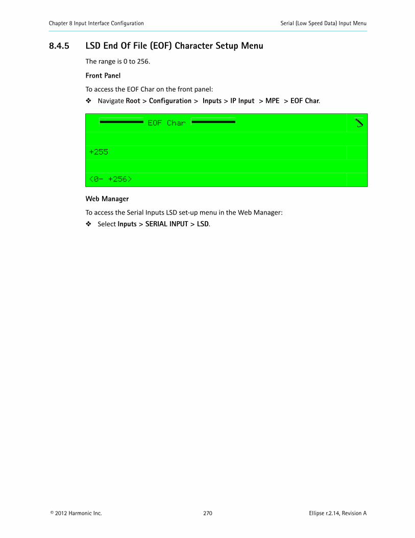
Chapter 8 Input Interface Configuration Serial (Low Speed Data) Input Menu
© 2012 Harmonic Inc. 270 Ellipse r.2.14, Revision A
8.4.5 LSD End Of File (EOF) Character Setup Menu
The range is 0 to 256.
Front Panel
To access the EOF Char on the front panel: Navigate Root > Configuration > Inputs > IP Input > MPE > EOF Char.
Web Manager
To access the Serial Inputs LSD set-up menu in the Web Manager: Select Inputs > SERIAL INPUT > LSD.
EOF Char
+255
<0- +256>
© 2012 Harmonic Inc. 271 Ellipse r.2.14, Revision A
Chapter 9Unit Configuration
This chapter details the Ellipse Series of Contribution Encoders unit configuration menus and parameters.
Topics:
General
Licensing
Ellipse System Menu/Tab
SNMP Traps Menu
Alarm Menu/Tab
Redundancy Menu/Tab Display Contrast Menu
9.1 GeneralThe Unit Configuration menu allows access to various menus and parameters that allow setting unit definitions, including: permissions, system definitions, clock setting and version information.
The available menus and options are (see Figure 9–1): Licensing menu – Displays the unit ID and allows entering a permission key
(see 9.2 Licensing). System menu/tab – Allows setting system information and functions
(see 9.3 Ellipse System Menu/Tab). SNMP Traps menu – Allows defining trap destination hosts for trap messages. Trap
message currently support raised and cancelled alarm notifications (see 9.4 SNMP Traps Menu).
Alarm menu/tab – Displays a list of alarms supported by the Ellipse (see 9.5 Alarm Menu/Tab).
Redundancy menu/tab – Use to configure device 1:1 hot:warm redundancy (see 9.6 Redundancy Menu/Tab).
Display Contrast menu – Allows setting the display contrast of the front panel LCD (see 9.7 Display Contrast Menu).
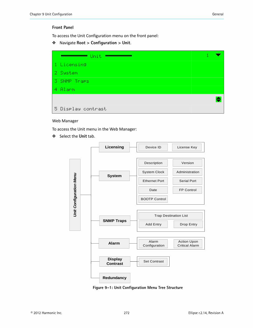
Chapter 9 Unit Configuration General
© 2012 Harmonic Inc. 272 Ellipse r.2.14, Revision A
Front Panel
To access the Unit Configuration menu on the front panel: Navigate Root > Configuration > Unit.
Web Manager
To access the Unit menu in the Web Manager: Select the Unit tab.
Figure 9–1: Unit Configuration Menu Tree Structure
Unit 1
1 Licensing
2 System
3 SNMP Traps
4 Alarm
5 Display contrast
Licensing Device ID License Key
System
SNMP Traps
Trap Destination List
Add Entry
Alarm
Display Contrast
Set Contrast
Drop Entry
Un
it C
on
fig
ura
tio
n M
enu
Version
Administration
Description
Date
System Clock
Serial Port
BOOTP Control
FP Control
Ethernet Port
Redundancy
Alarm Configuration
Action Upon Critical Alarm

Chapter 9 Unit Configuration Licensing
© 2012 Harmonic Inc. 273 Ellipse r.2.14, Revision A
9.2 LicensingLicensing allows entering a permission key. A product license key has different acquired features allowing access to various advanced encoder capabilities, such as: 4:2:2 video format, Dolby encoding, 16 QAM permission, DVB-S2, and so on (the available features according to the current license key are displayed on the Permissions screen, see 3.5.2 Permissions on page 62).
The License menu enables access to two sub-menus: Device ID – Manages the unit ID number (see 9.2.1 Device ID). License Key – Manages the license key. Allows viewing and entering a new license key
number (see 9.2.2 License Key).
Front Panel
To access the Licensing menu on the front panel: Navigate Root > Configuration > Unit > Licensing.
Web Manager
To access the Licensing menu in the Web Manager: Select Unit > Licensing (see Figure 9–2).
Figure 9–2: Web Managed Licensing Display
Licensing
1 Device ID
2 License Key
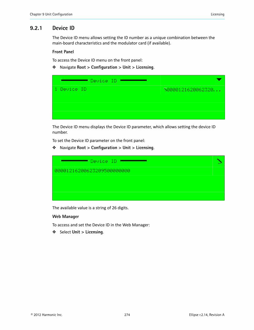
Chapter 9 Unit Configuration Licensing
© 2012 Harmonic Inc. 274 Ellipse r.2.14, Revision A
9.2.1 Device ID
The Device ID menu allows setting the ID number as a unique combination between the main-board characteristics and the modulator card (if available).
Front Panel
To access the Device ID menu on the front panel: Navigate Root > Configuration > Unit > Licensing.
The Device ID menu displays the Device ID parameter, which allows setting the device ID number.
To set the Device ID parameter on the front panel: Navigate Root > Configuration > Unit > Licensing.
The available value is a string of 26 digits.
Web Manager
To access and set the Device ID in the Web Manager: Select Unit > Licensing.
Device ID
1 Device ID 0000121620062320...
Device ID
00001216200623209500000000
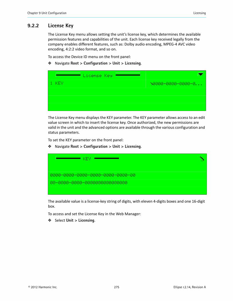
Chapter 9 Unit Configuration Licensing
© 2012 Harmonic Inc. 275 Ellipse r.2.14, Revision A
9.2.2 License Key
The License Key menu allows setting the unit’s license key, which determines the available permission features and capabilities of the unit. Each license key received legally from the company enables different features, such as: Dolby audio encoding, MPEG-4 AVC video encoding, 4:2:2 video format, and so on.
To access the Device ID menu on the front panel: Navigate Root > Configuration > Unit > Licensing.
The License Key menu displays the KEY parameter. The KEY parameter allows access to an edit value screen in which to insert the license key. Once authorized, the new permissions are valid in the unit and the advanced options are available through the various configuration and status parameters.
To set the KEY parameter on the front panel: Navigate Root > Configuration > Unit > Licensing.
The available value is a license-key string of digits, with eleven 4-digits boxes and one 16-digit box.
To access and set the License Key in the Web Manager: Select Unit > Licensing.
License Key
1 KEY 0000-0000-0000-0...
KEY
0000-0000-0000-0000-0000-0000-00
00-0000-0000-0000000000000000
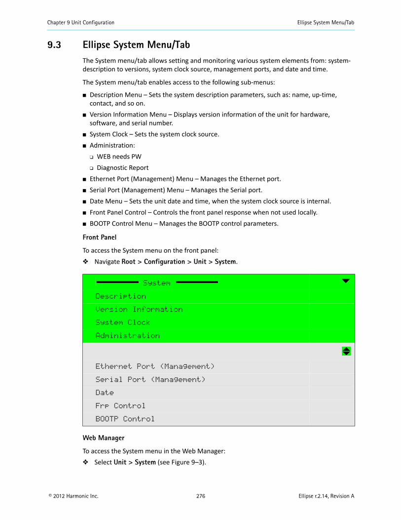
Chapter 9 Unit Configuration Ellipse System Menu/Tab
© 2012 Harmonic Inc. 276 Ellipse r.2.14, Revision A
9.3 Ellipse System Menu/TabThe System menu/tab allows setting and monitoring various system elements from: system-description to versions, system clock source, management ports, and date and time.
The System menu/tab enables access to the following sub-menus:
Description Menu – Sets the system description parameters, such as: name, up-time, contact, and so on.
Version Information Menu – Displays version information of the unit for hardware, software, and serial number.
System Clock – Sets the system clock source. Administration:
WEB needs PW Diagnostic Report
Ethernet Port (Management) Menu – Manages the Ethernet port. Serial Port (Management) Menu – Manages the Serial port. Date Menu – Sets the unit date and time, when the system clock source is internal. Front Panel Control – Controls the front panel response when not used locally. BOOTP Control Menu – Manages the BOOTP control parameters.
Front Panel
To access the System menu on the front panel: Navigate Root > Configuration > Unit > System.
Web Manager
To access the System menu in the Web Manager: Select Unit > System (see Figure 9–3).
System
Description
Version Information
System Clock
Administration
Ethernet Port (Management)
Serial Port (Management)
Date
Frp Control
BOOTP Control
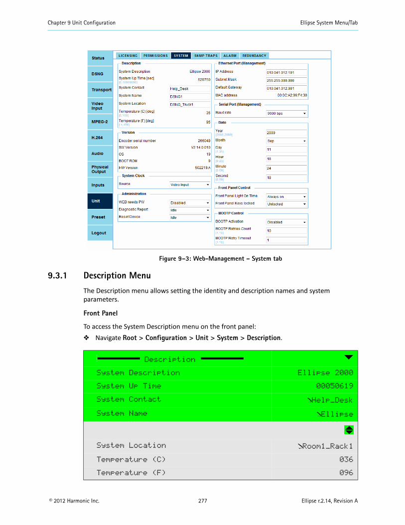
Chapter 9 Unit Configuration Ellipse System Menu/Tab
© 2012 Harmonic Inc. 277 Ellipse r.2.14, Revision A
Figure 9–3: Web-Management – System tab
9.3.1 Description Menu
The Description menu allows setting the identity and description names and system parameters.
Front Panel
To access the System Description menu on the front panel: Navigate Root > Configuration > Unit > System > Description.
Description
System Description Ellipse 2000
System Up Time 00050619
System Contact Help_Desk
System Name Ellipse
System Location Room1_Rack1
Temperature (C) 036
Temperature (F) 096
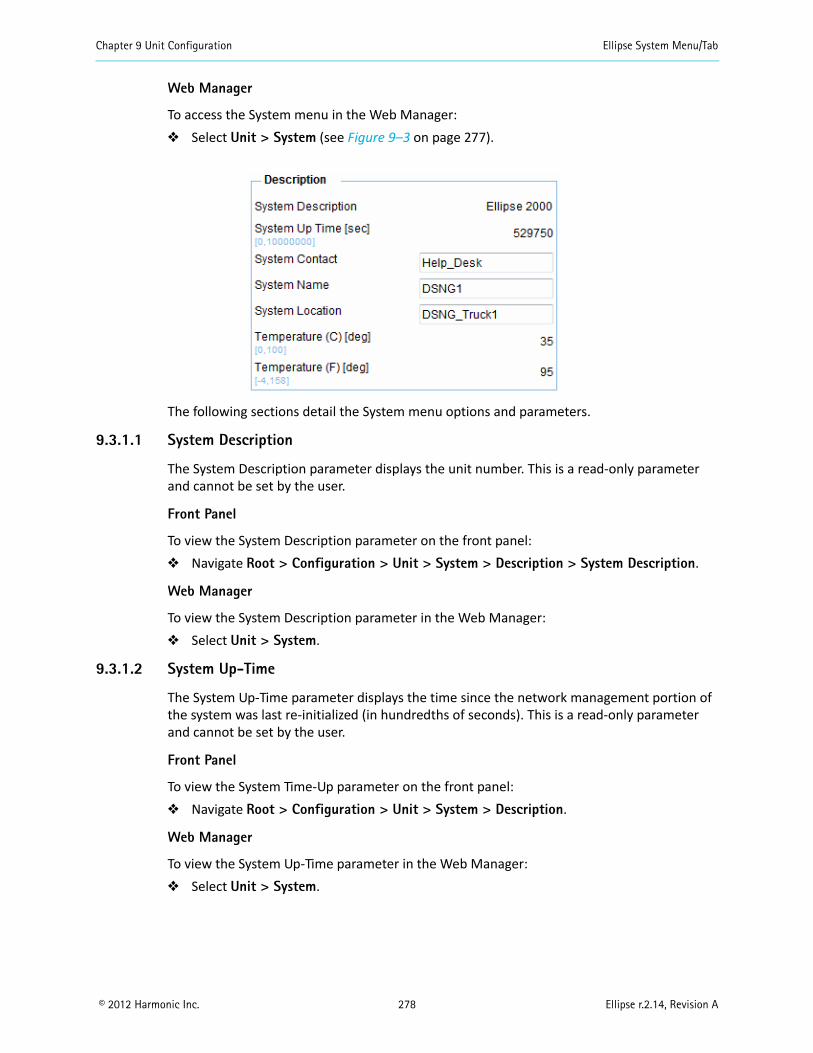
Chapter 9 Unit Configuration Ellipse System Menu/Tab
© 2012 Harmonic Inc. 278 Ellipse r.2.14, Revision A
Web Manager
To access the System menu in the Web Manager: Select Unit > System (see Figure 9–3 on page 277).
The following sections detail the System menu options and parameters.
9.3.1.1 System Description
The System Description parameter displays the unit number. This is a read-only parameter and cannot be set by the user.
Front Panel
To view the System Description parameter on the front panel: Navigate Root > Configuration > Unit > System > Description > System Description.
Web Manager
To view the System Description parameter in the Web Manager: Select Unit > System.
9.3.1.2 System Up-Time
The System Up-Time parameter displays the time since the network management portion of the system was last re-initialized (in hundredths of seconds). This is a read-only parameter and cannot be set by the user.
Front Panel
To view the System Time-Up parameter on the front panel: Navigate Root > Configuration > Unit > System > Description.
Web Manager
To view the System Up-Time parameter in the Web Manager: Select Unit > System.
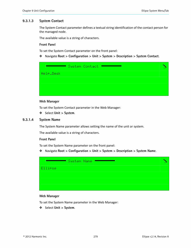
Chapter 9 Unit Configuration Ellipse System Menu/Tab
© 2012 Harmonic Inc. 279 Ellipse r.2.14, Revision A
9.3.1.3 System Contact
The System Contact parameter defines a textual string identification of the contact person for the managed node.
The available value is a string of characters.
Front Panel
To set the System Contact parameter on the front panel: Navigate Root > Configuration > Unit > System > Description > System Contact.
Web Manager
To set the System Contact parameter in the Web Manager: Select Unit > System.
9.3.1.4 System Name
The System Name parameter allows setting the name of the unit or system.
The available value is a string of characters.
Front Panel
To set the System Name parameter on the front panel: Navigate Root > Configuration > Unit > System > Description > System Name.
Web Manager
To set the System Name parameter in the Web Manager: Select Unit > System.
System Contact
Help_Desk
System Name
Ellipse
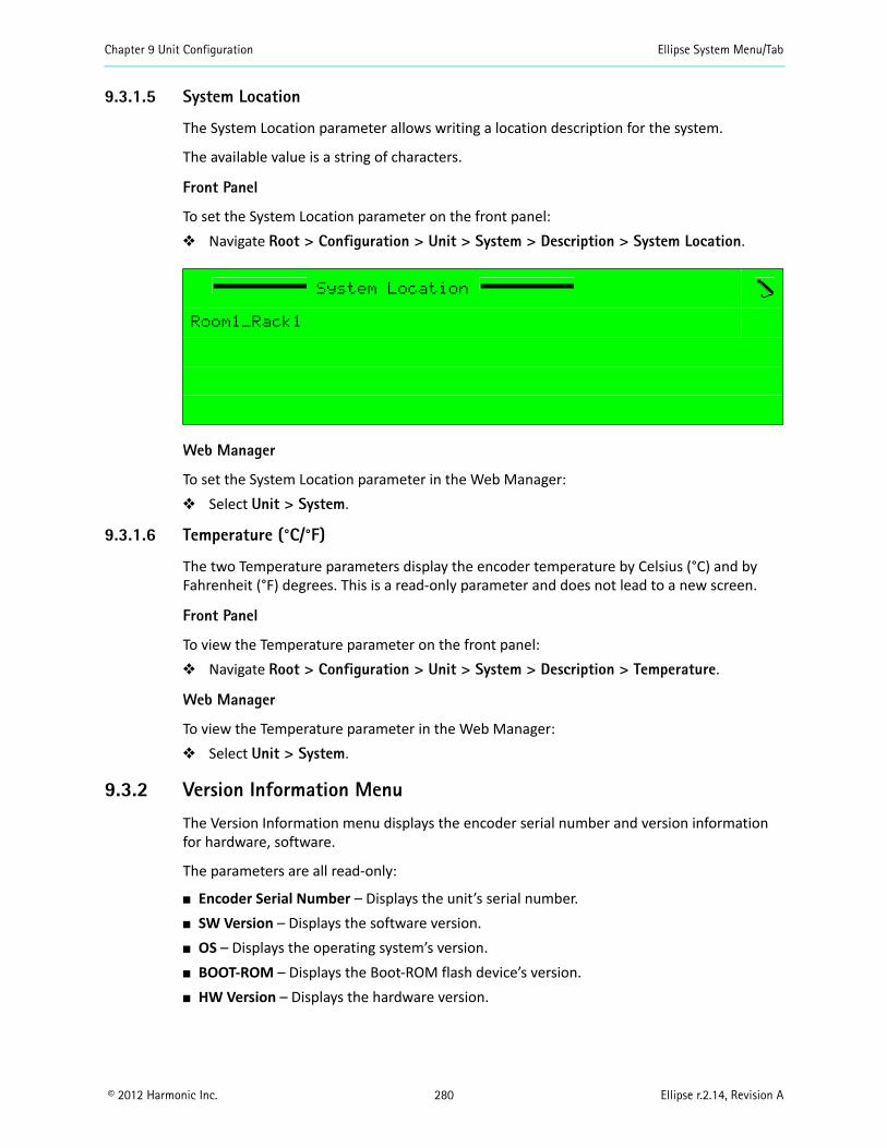
Chapter 9 Unit Configuration Ellipse System Menu/Tab
© 2012 Harmonic Inc. 280 Ellipse r.2.14, Revision A
9.3.1.5 System Location
The System Location parameter allows writing a location description for the system.
The available value is a string of characters.
Front Panel
To set the System Location parameter on the front panel: Navigate Root > Configuration > Unit > System > Description > System Location.
Web Manager
To set the System Location parameter in the Web Manager: Select Unit > System.
9.3.1.6 Temperature (°C/°F)
The two Temperature parameters display the encoder temperature by Celsius (°C) and by Fahrenheit (°F) degrees. This is a read-only parameter and does not lead to a new screen.
Front Panel
To view the Temperature parameter on the front panel: Navigate Root > Configuration > Unit > System > Description > Temperature.
Web Manager
To view the Temperature parameter in the Web Manager: Select Unit > System.
9.3.2 Version Information Menu
The Version Information menu displays the encoder serial number and version information for hardware, software.
The parameters are all read-only:
Encoder Serial Number – Displays the unit’s serial number. SW Version – Displays the software version. OS – Displays the operating system’s version. BOOT-ROM – Displays the Boot-ROM flash device’s version. HW Version – Displays the hardware version.
System Location
Room1_Rack1
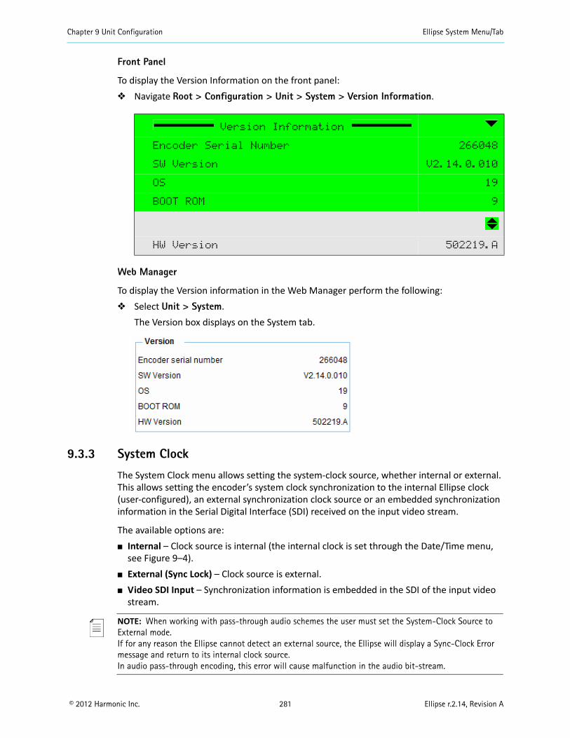
Chapter 9 Unit Configuration Ellipse System Menu/Tab
© 2012 Harmonic Inc. 281 Ellipse r.2.14, Revision A
Front Panel
To display the Version Information on the front panel: Navigate Root > Configuration > Unit > System > Version Information.
Web Manager
To display the Version information in the Web Manager perform the following: Select Unit > System.
The Version box displays on the System tab.
9.3.3 System Clock
The System Clock menu allows setting the system-clock source, whether internal or external. This allows setting the encoder’s system clock synchronization to the internal Ellipse clock (user-configured), an external synchronization clock source or an embedded synchronization information in the Serial Digital Interface (SDI) received on the input video stream.
The available options are: Internal – Clock source is internal (the internal clock is set through the Date/Time menu,
see Figure 9–4). External (Sync Lock) – Clock source is external. Video SDI Input – Synchronization information is embedded in the SDI of the input video
stream.
NOTE: When working with pass-through audio schemes the user must set the System-Clock Source to External mode.If for any reason the Ellipse cannot detect an external source, the Ellipse will display a Sync-Clock Error message and return to its internal clock source.In audio pass-through encoding, this error will cause malfunction in the audio bit-stream.
Version Information
Encoder Serial Number 266048
SW Version V2.14.0.010
OS 19
BOOT ROM 9
HW Version 502219.A
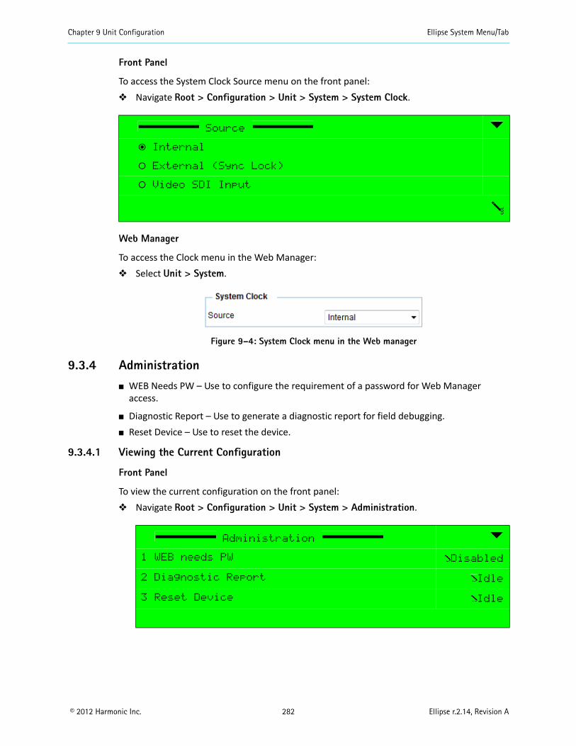
Chapter 9 Unit Configuration Ellipse System Menu/Tab
© 2012 Harmonic Inc. 282 Ellipse r.2.14, Revision A
Front Panel
To access the System Clock Source menu on the front panel: Navigate Root > Configuration > Unit > System > System Clock.
Web Manager
To access the Clock menu in the Web Manager: Select Unit > System.
Figure 9–4: System Clock menu in the Web manager
9.3.4 Administration WEB Needs PW – Use to configure the requirement of a password for Web Manager
access.
Diagnostic Report – Use to generate a diagnostic report for field debugging. Reset Device – Use to reset the device.
9.3.4.1 Viewing the Current Configuration
Front Panel
To view the current configuration on the front panel: Navigate Root > Configuration > Unit > System > Administration.
Source
ƒ Internal
‚ External (Sync Lock)
‚ Video SDI Input
Administration
1 WEB needs PW Disabled
2 Diagnostic Report Idle
3 Reset Device Idle
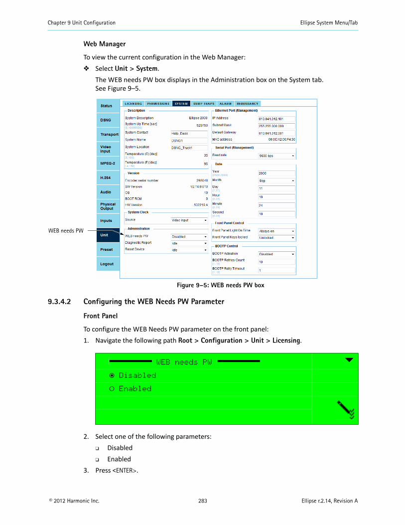
Chapter 9 Unit Configuration Ellipse System Menu/Tab
© 2012 Harmonic Inc. 283 Ellipse r.2.14, Revision A
Web Manager
To view the current configuration in the Web Manager: Select Unit > System.
The WEB needs PW box displays in the Administration box on the System tab.See Figure 9–5.
Figure 9–5: WEB needs PW box
9.3.4.2 Configuring the WEB Needs PW Parameter
Front Panel
To configure the WEB Needs PW parameter on the front panel:1. Navigate the following path Root > Configuration > Unit > Licensing.
2. Select one of the following parameters: Disabled Enabled
3. Press <ENTER>.
WEB needs PW
ƒ Disabled
‚ Enabled
WEB needs PW
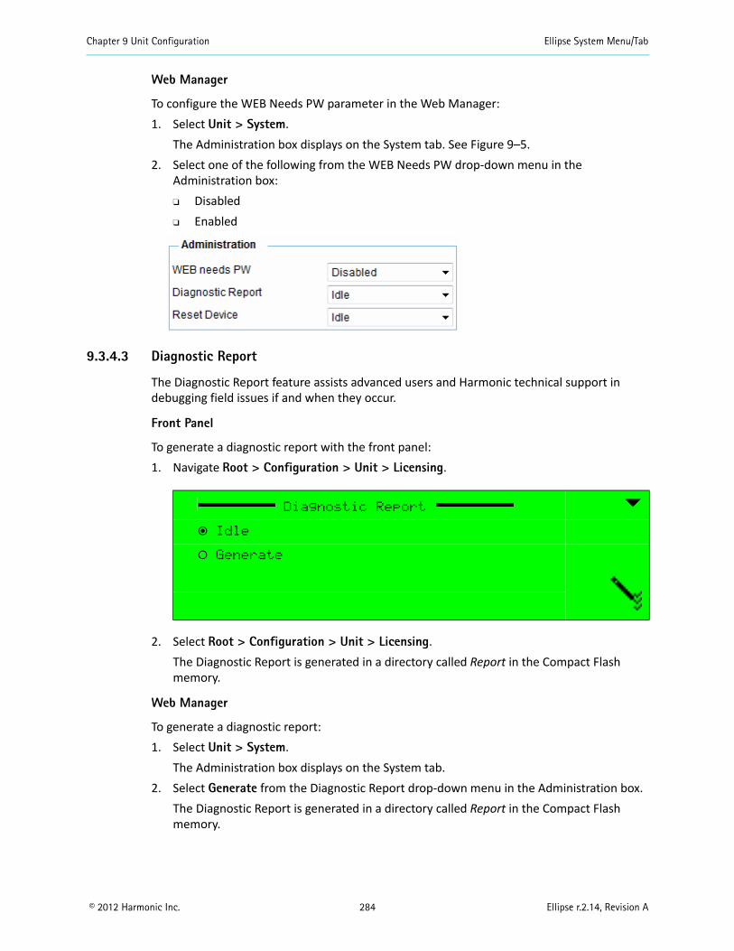
Chapter 9 Unit Configuration Ellipse System Menu/Tab
© 2012 Harmonic Inc. 284 Ellipse r.2.14, Revision A
Web Manager
To configure the WEB Needs PW parameter in the Web Manager:1. Select Unit > System.
The Administration box displays on the System tab. See Figure 9–5.2. Select one of the following from the WEB Needs PW drop-down menu in the
Administration box: Disabled Enabled
9.3.4.3 Diagnostic Report
The Diagnostic Report feature assists advanced users and Harmonic technical support in debugging field issues if and when they occur.
Front Panel
To generate a diagnostic report with the front panel:1. Navigate Root > Configuration > Unit > Licensing.
2. Select Root > Configuration > Unit > Licensing.The Diagnostic Report is generated in a directory called Report in the Compact Flash memory.
Web Manager
To generate a diagnostic report:1. Select Unit > System.
The Administration box displays on the System tab.2. Select Generate from the Diagnostic Report drop-down menu in the Administration box.
The Diagnostic Report is generated in a directory called Report in the Compact Flash memory.
Diagnostic Report
ƒ Idle
‚ Generate
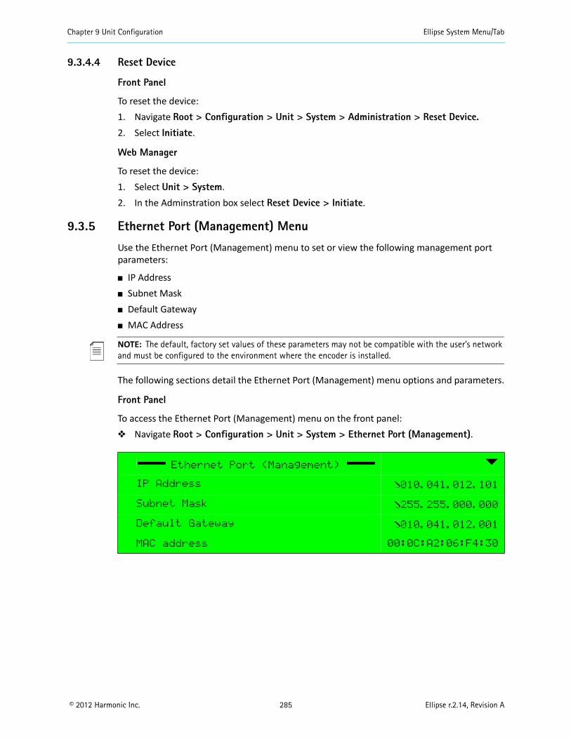
Chapter 9 Unit Configuration Ellipse System Menu/Tab
© 2012 Harmonic Inc. 285 Ellipse r.2.14, Revision A
9.3.4.4 Reset Device
Front Panel
To reset the device:1. Navigate Root > Configuration > Unit > System > Administration > Reset Device.2. Select Initiate.
Web Manager
To reset the device:1. Select Unit > System.2. In the Adminstration box select Reset Device > Initiate.
9.3.5 Ethernet Port (Management) Menu
Use the Ethernet Port (Management) menu to set or view the following management port parameters:
IP Address Subnet Mask Default Gateway MAC Address
NOTE: The default, factory set values of these parameters may not be compatible with the user’s network and must be configured to the environment where the encoder is installed.
The following sections detail the Ethernet Port (Management) menu options and parameters.
Front Panel
To access the Ethernet Port (Management) menu on the front panel: Navigate Root > Configuration > Unit > System > Ethernet Port (Management).
Ethernet Port (Management)
IP Address 010.041.012.101
Subnet Mask 255.255.000.000
Default Gateway 010.041.012.001
MAC address 00:0C:A2:06:F4:30
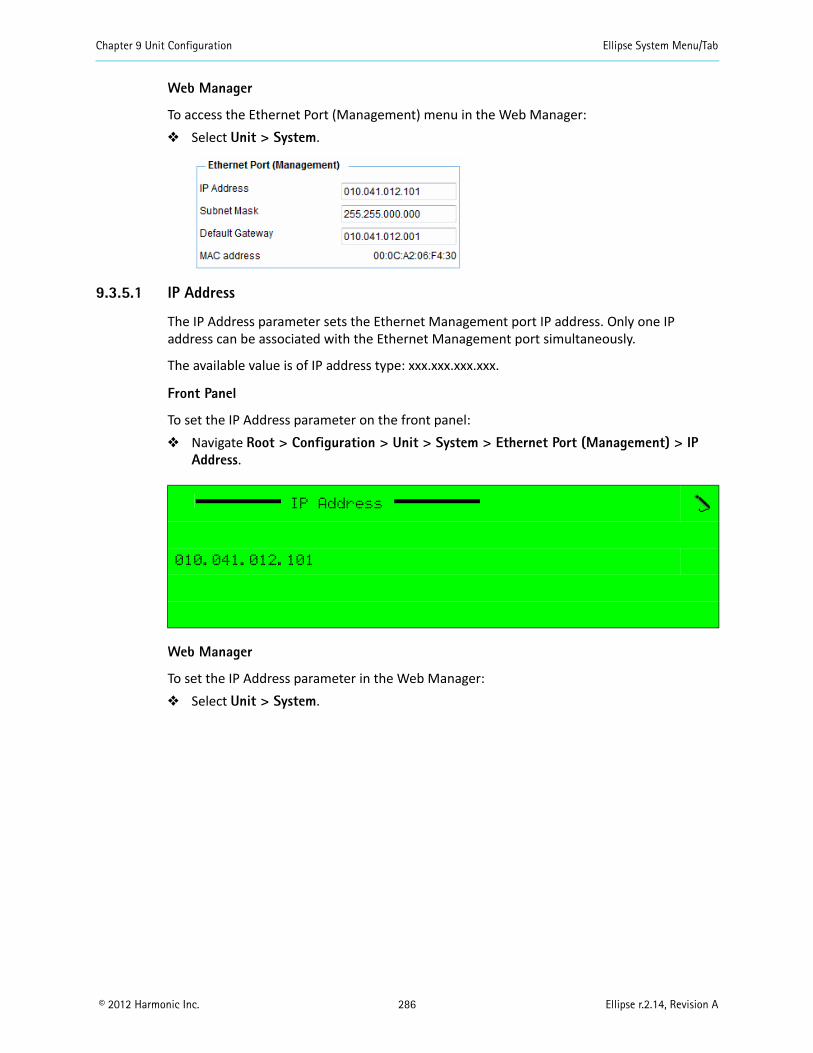
Chapter 9 Unit Configuration Ellipse System Menu/Tab
© 2012 Harmonic Inc. 286 Ellipse r.2.14, Revision A
Web Manager
To access the Ethernet Port (Management) menu in the Web Manager: Select Unit > System.
9.3.5.1 IP Address
The IP Address parameter sets the Ethernet Management port IP address. Only one IP address can be associated with the Ethernet Management port simultaneously.
The available value is of IP address type: xxx.xxx.xxx.xxx.
Front Panel
To set the IP Address parameter on the front panel: Navigate Root > Configuration > Unit > System > Ethernet Port (Management) > IP
Address.
Web Manager
To set the IP Address parameter in the Web Manager: Select Unit > System.
IP Address
010.041.012.101
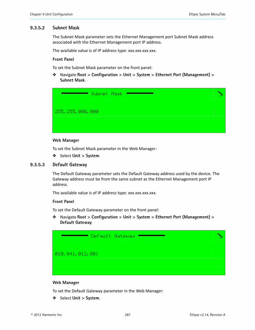
Chapter 9 Unit Configuration Ellipse System Menu/Tab
© 2012 Harmonic Inc. 287 Ellipse r.2.14, Revision A
9.3.5.2 Subnet Mask
The Subnet Mask parameter sets the Ethernet Management port Subnet Mask address associated with the Ethernet Management port IP address.
The available value is of IP address type: xxx.xxx.xxx.xxx.
Front Panel
To set the Subnet Mask parameter on the front panel: Navigate Root > Configuration > Unit > System > Ethernet Port (Management) >
Subnet Mask.
Web Manager
To set the Subnet Mask parameter in the Web Manager: Select Unit > System.
9.3.5.3 Default Gateway
The Default Gateway parameter sets the Default Gateway address used by the device. The Gateway address must be from the same subnet as the Ethernet Management port IP address.
The available value is of IP address type: xxx.xxx.xxx.xxx.
Front Panel
To set the Default Gateway parameter on the front panel: Navigate Root > Configuration > Unit > System > Ethernet Port (Management) >
Default Gateway.
Web Manager
To set the Default Gateway parameter in the Web Manager: Select Unit > System.
Subnet Mask
255.255.000.000
Default Gateway
010.041.012.001
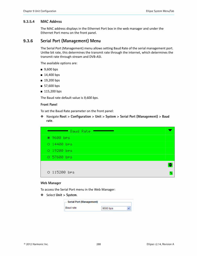
Chapter 9 Unit Configuration Ellipse System Menu/Tab
© 2012 Harmonic Inc. 288 Ellipse r.2.14, Revision A
9.3.5.4 MAC Address
The MAC address displays in the Ethernet Port box in the web manager and under the Ethernet Port menu on the front panel.
9.3.6 Serial Port (Management) Menu
The Serial Port (Management) menu allows setting Baud Rate of the serial management port. Unlike bit rate, this determines the transmit rate through the internet, which determines the transmit rate through stream and DVB-ASI.
The available options are:
9,600 bps 14,400 bps 19,200 bps 57,600 bps 115,200 bps
The Baud rate default value is 9,600 bps.
Front Panel
To set the Baud Rate parameter on the front panel: Navigate Root > Configuration > Unit > System > Serial Port (Management) > Baud
rate.
Web Manager
To access the Serial Port menu in the Web Manager: Select Unit > System.
Baud Rate
ƒ 9600 bps
‚ 14400 bps
‚ 19200 bps
‚ 57600 bps
‚ 115200 bps
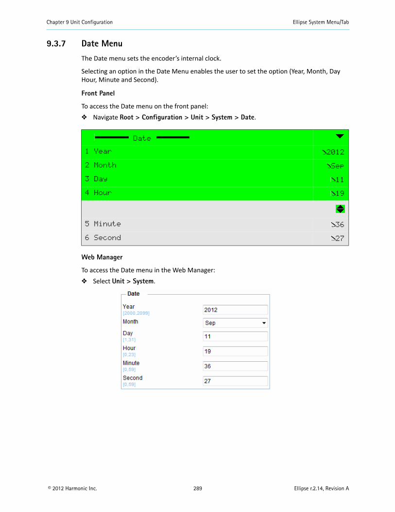
Chapter 9 Unit Configuration Ellipse System Menu/Tab
© 2012 Harmonic Inc. 289 Ellipse r.2.14, Revision A
9.3.7 Date Menu
The Date menu sets the encoder’s internal clock.
Selecting an option in the Date Menu enables the user to set the option (Year, Month, Day Hour, Minute and Second).
Front Panel
To access the Date menu on the front panel: Navigate Root > Configuration > Unit > System > Date.
Web Manager
To access the Date menu in the Web Manager: Select Unit > System.
Date
1 Year 2012
2 Month Sep
3 Day 11
4 Hour 19
5 Minute 36
6 Second 27
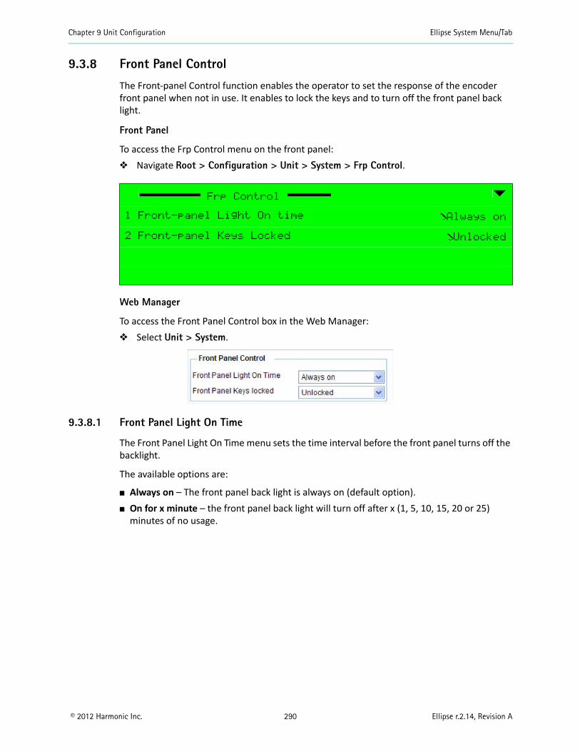
Chapter 9 Unit Configuration Ellipse System Menu/Tab
© 2012 Harmonic Inc. 290 Ellipse r.2.14, Revision A
9.3.8 Front Panel Control
The Front-panel Control function enables the operator to set the response of the encoder front panel when not in use. It enables to lock the keys and to turn off the front panel back light.
Front Panel
To access the Frp Control menu on the front panel: Navigate Root > Configuration > Unit > System > Frp Control.
Web Manager
To access the Front Panel Control box in the Web Manager: Select Unit > System.
9.3.8.1 Front Panel Light On Time
The Front Panel Light On Time menu sets the time interval before the front panel turns off the backlight.
The available options are:
Always on – The front panel back light is always on (default option). On for x minute – the front panel back light will turn off after x (1, 5, 10, 15, 20 or 25)
minutes of no usage.
Frp Control
1 Front-panel Light On time Always on
2 Front-panel Keys Locked Unlocked
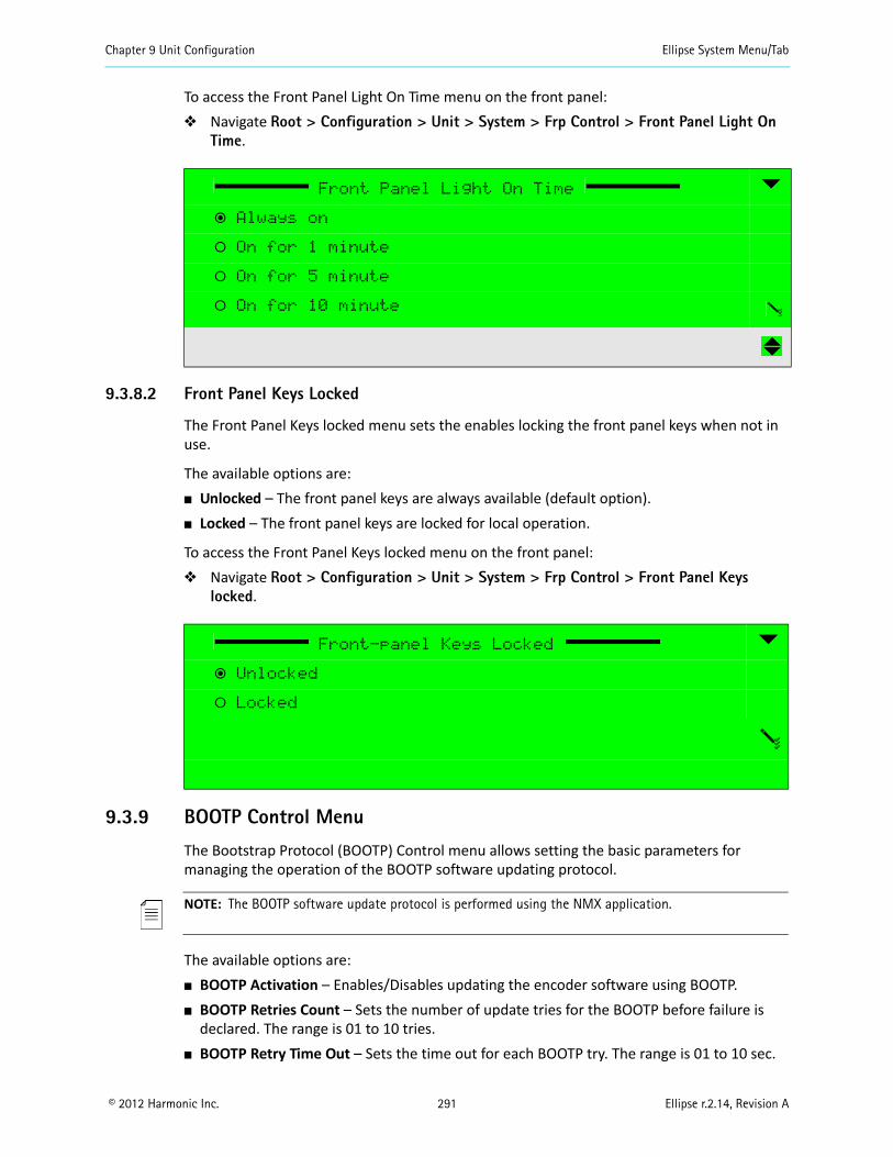
Chapter 9 Unit Configuration Ellipse System Menu/Tab
© 2012 Harmonic Inc. 291 Ellipse r.2.14, Revision A
To access the Front Panel Light On Time menu on the front panel: Navigate Root > Configuration > Unit > System > Frp Control > Front Panel Light On
Time.
9.3.8.2 Front Panel Keys Locked
The Front Panel Keys locked menu sets the enables locking the front panel keys when not in use.
The available options are: Unlocked – The front panel keys are always available (default option). Locked – The front panel keys are locked for local operation.
To access the Front Panel Keys locked menu on the front panel: Navigate Root > Configuration > Unit > System > Frp Control > Front Panel Keys
locked.
9.3.9 BOOTP Control Menu
The Bootstrap Protocol (BOOTP) Control menu allows setting the basic parameters for managing the operation of the BOOTP software updating protocol.
NOTE: The BOOTP software update protocol is performed using the NMX application.
The available options are: BOOTP Activation – Enables/Disables updating the encoder software using BOOTP. BOOTP Retries Count – Sets the number of update tries for the BOOTP before failure is
declared. The range is 01 to 10 tries. BOOTP Retry Time Out – Sets the time out for each BOOTP try. The range is 01 to 10 sec.
Front Panel Light On Time
ƒ Always on
‚ On for 1 minute
‚ On for 5 minute
‚ On for 10 minute
Front-panel Keys Locked
ƒ Unlocked
‚ Locked
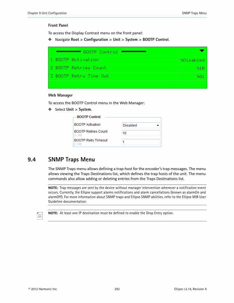
Chapter 9 Unit Configuration SNMP Traps Menu
© 2012 Harmonic Inc. 292 Ellipse r.2.14, Revision A
Front Panel
To access the Display Contrast menu on the front panel: Navigate Root > Configuration > Unit > System > BOOTP Control.
Web Manager
To access the BOOTP Control menu in the Web Manager: Select Unit > System.
9.4 SNMP Traps MenuThe SNMP Traps menu allows defining a trap-host for the encoder’s trap messages. The menu allows viewing the Traps Destinations list, which defines the trap hosts of the unit. The menu commands also allow adding or deleting entries from the Traps Destinations list.
NOTE: Trap messages are sent by the device without manager intervention whenever a notification event occurs. Currently, the Ellipse support alarms notifications and alarm cancellations (known as alarmOn and alarmOff). For more information about SNMP traps and Ellipse SNMP abilities, refer to the Ellipse MIB User Guideline documentation.
NOTE: At least one IP destination must be defined to enable the Drop Entry option.
BOOTP Control
1 BOOTP Activation Disabled
2 BOOTP Retries Count 10
3 BOOTP Retry Time Out 01
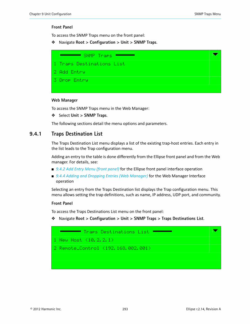
Chapter 9 Unit Configuration SNMP Traps Menu
© 2012 Harmonic Inc. 293 Ellipse r.2.14, Revision A
Front Panel
To access the SNMP Traps menu on the front panel: Navigate Root > Configuration > Unit > SNMP Traps.
Web Manager
To access the SNMP Traps menu in the Web Manager: Select Unit > SNMP Traps.
The following sections detail the menu options and parameters.
9.4.1 Traps Destination List
The Traps Destination List menu displays a list of the existing trap-host entries. Each entry in the list leads to the Trap configuration menu.
Adding an entry to the table is done differently from the Ellipse front panel and from the Web manager. For details, see: 9.4.2 Add Entry Menu (front panel) for the Ellipse front panel interface operation 9.4.4 Adding and Dropping Entries (Web Manager) for the Web Manager Interface
operation
Selecting an entry from the Traps Destination list displays the Trap configuration menu. This menu allows setting the trap definitions, such as name, IP address, UDP port, and community.
Front Panel
To access the Traps Destinations List menu on the front panel: Navigate Root > Configuration > Unit > SNMP Traps > Traps Destinations List.
SNMP Traps
1 Traps Destinations List
2 Add Entry
3 Drop Entry
Traps Destinations List
1 New Host (10.2.2.1)
2 Remote_Control (192.168.002.001)
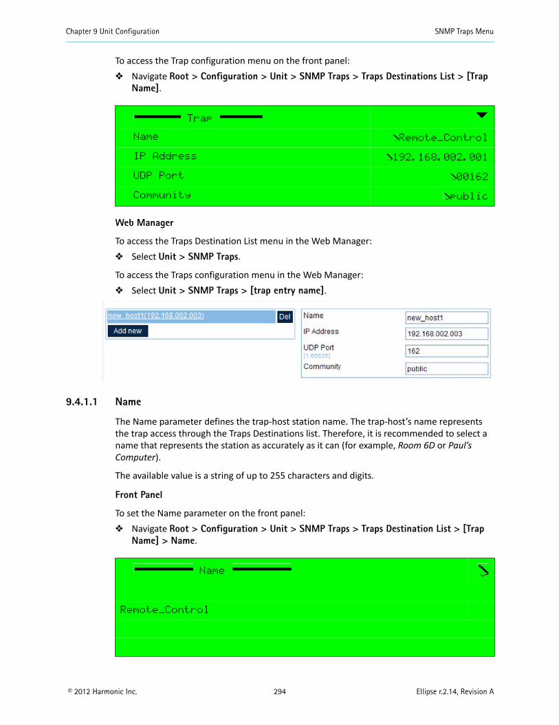
Chapter 9 Unit Configuration SNMP Traps Menu
© 2012 Harmonic Inc. 294 Ellipse r.2.14, Revision A
To access the Trap configuration menu on the front panel: Navigate Root > Configuration > Unit > SNMP Traps > Traps Destinations List > [Trap
Name].
Web Manager
To access the Traps Destination List menu in the Web Manager: Select Unit > SNMP Traps.
To access the Traps configuration menu in the Web Manager: Select Unit > SNMP Traps > [trap entry name].
9.4.1.1 Name
The Name parameter defines the trap-host station name. The trap-host’s name represents the trap access through the Traps Destinations list. Therefore, it is recommended to select a name that represents the station as accurately as it can (for example, Room 6D or Paul’s Computer).
The available value is a string of up to 255 characters and digits.
Front Panel
To set the Name parameter on the front panel: Navigate Root > Configuration > Unit > SNMP Traps > Traps Destination List > [Trap
Name] > Name.
Trap
Name Remote_Control
IP Address 192.168.002.001
UDP Port 00162
Community public
Name
Remote_Control
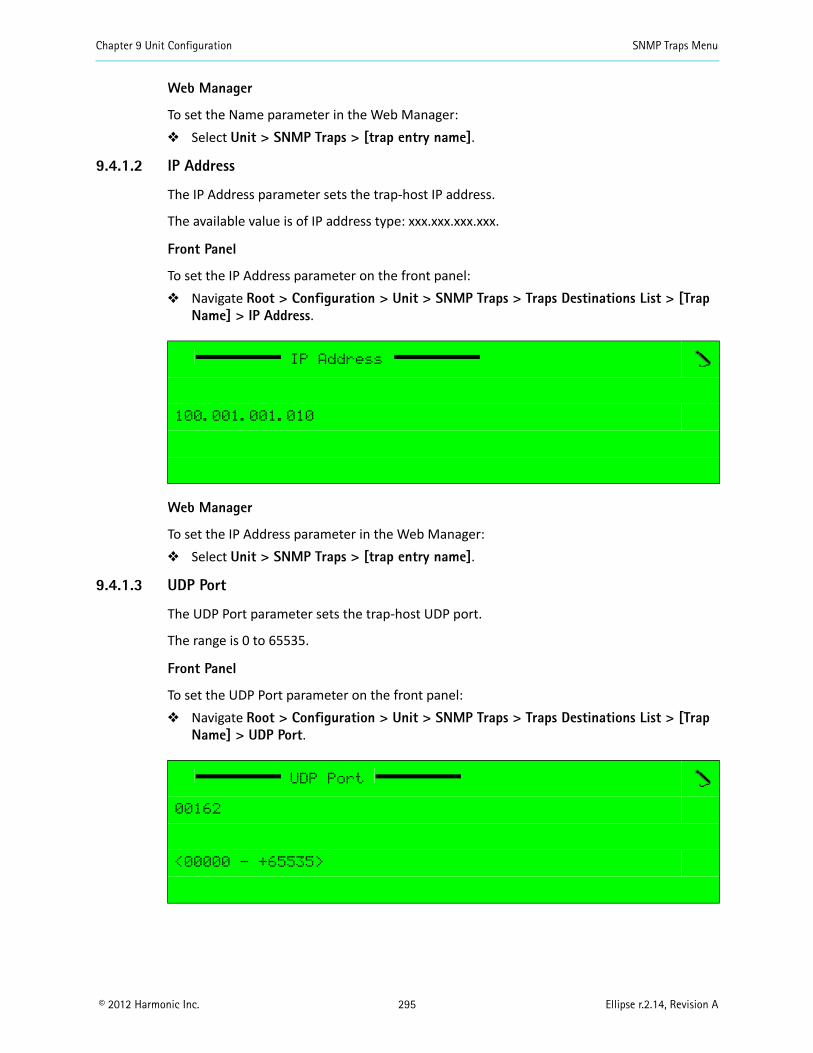
Chapter 9 Unit Configuration SNMP Traps Menu
© 2012 Harmonic Inc. 295 Ellipse r.2.14, Revision A
Web Manager
To set the Name parameter in the Web Manager: Select Unit > SNMP Traps > [trap entry name].
9.4.1.2 IP Address
The IP Address parameter sets the trap-host IP address.
The available value is of IP address type: xxx.xxx.xxx.xxx.
Front Panel
To set the IP Address parameter on the front panel: Navigate Root > Configuration > Unit > SNMP Traps > Traps Destinations List > [Trap
Name] > IP Address.
Web Manager
To set the IP Address parameter in the Web Manager: Select Unit > SNMP Traps > [trap entry name].
9.4.1.3 UDP Port
The UDP Port parameter sets the trap-host UDP port.
The range is 0 to 65535.
Front Panel
To set the UDP Port parameter on the front panel: Navigate Root > Configuration > Unit > SNMP Traps > Traps Destinations List > [Trap
Name] > UDP Port.
IP Address
100.001.001.010
UDP Port
00162
<00000 - +65535>
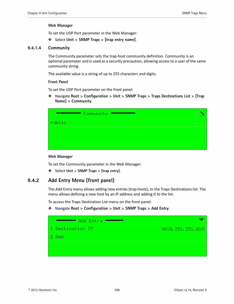
Chapter 9 Unit Configuration SNMP Traps Menu
© 2012 Harmonic Inc. 296 Ellipse r.2.14, Revision A
Web Manager
To set the UDP Port parameter in the Web Manager: Select Unit > SNMP Traps > [trap entry name].
9.4.1.4 Community
The Community parameter sets the trap-host community definition. Community is an optional parameter and is used as a security precaution, allowing access to a user of the same community string.
The available value is a string of up to 255 characters and digits.
Front Panel
To set the UDP Port parameter on the front panel: Navigate Root > Configuration > Unit > SNMP Traps > Traps Destinations List > [Trap
Name] > Community.
Web Manager
To set the Community parameter in the Web Manager: Select Unit > SNMP Traps > [trap entry].
9.4.2 Add Entry Menu (front panel)
The Add Entry menu allows adding new entries (trap hosts), to the Traps Destinations list. The menu allows defining a new host by an IP address and adding it to the list.
To access the Traps Destination List menu on the front panel: Navigate Root > Configuration > Unit > SNMP Traps > Add Entry.
Community
public
Add Entry
1 Destination IP 010.251.251.010
2 Add
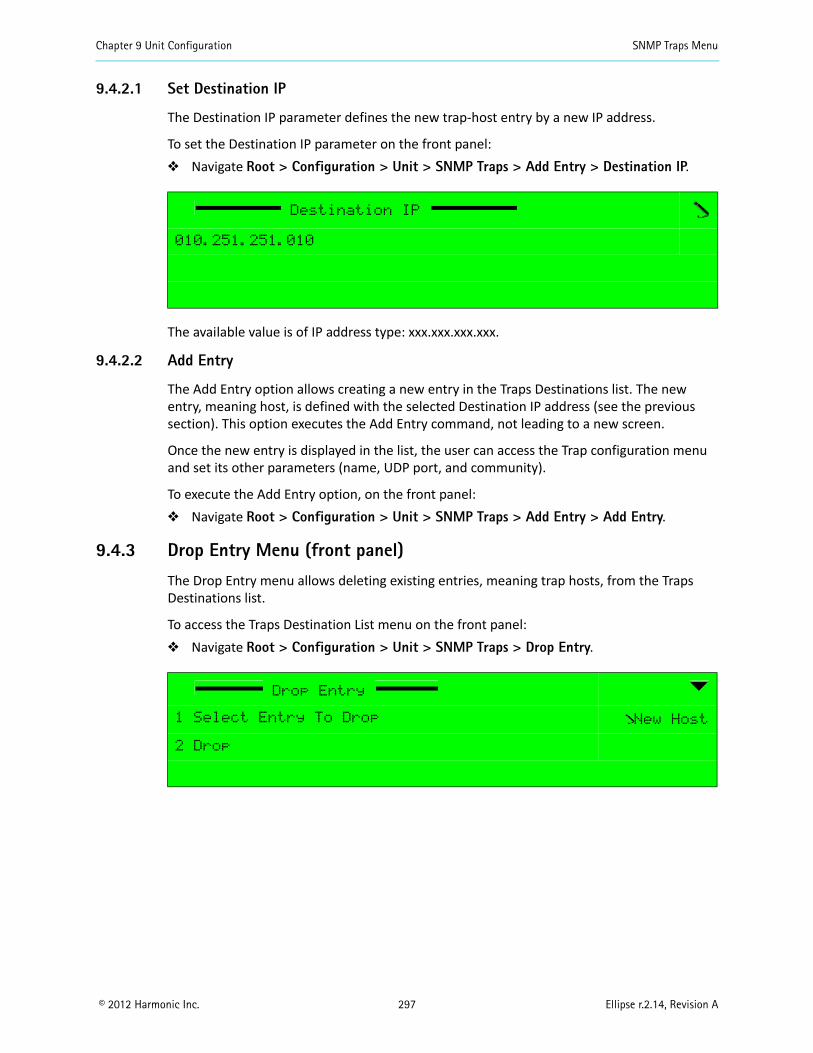
Chapter 9 Unit Configuration SNMP Traps Menu
© 2012 Harmonic Inc. 297 Ellipse r.2.14, Revision A
9.4.2.1 Set Destination IP
The Destination IP parameter defines the new trap-host entry by a new IP address.
To set the Destination IP parameter on the front panel: Navigate Root > Configuration > Unit > SNMP Traps > Add Entry > Destination IP.
The available value is of IP address type: xxx.xxx.xxx.xxx.
9.4.2.2 Add Entry
The Add Entry option allows creating a new entry in the Traps Destinations list. The new entry, meaning host, is defined with the selected Destination IP address (see the previous section). This option executes the Add Entry command, not leading to a new screen.
Once the new entry is displayed in the list, the user can access the Trap configuration menu and set its other parameters (name, UDP port, and community).
To execute the Add Entry option, on the front panel: Navigate Root > Configuration > Unit > SNMP Traps > Add Entry > Add Entry.
9.4.3 Drop Entry Menu (front panel)
The Drop Entry menu allows deleting existing entries, meaning trap hosts, from the Traps Destinations list.
To access the Traps Destination List menu on the front panel: Navigate Root > Configuration > Unit > SNMP Traps > Drop Entry.
Destination IP
010.251.251.010
Drop Entry
1 Select Entry To Drop New Host
2 Drop
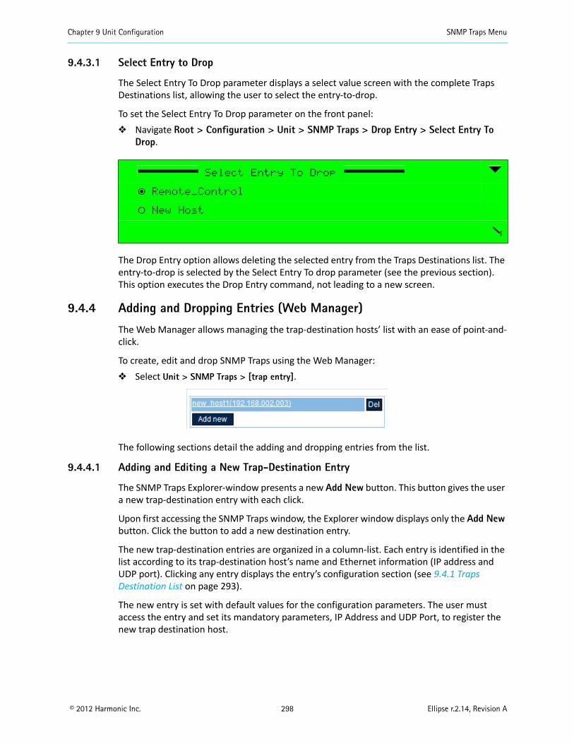
Chapter 9 Unit Configuration SNMP Traps Menu
© 2012 Harmonic Inc. 298 Ellipse r.2.14, Revision A
9.4.3.1 Select Entry to Drop
The Select Entry To Drop parameter displays a select value screen with the complete Traps Destinations list, allowing the user to select the entry-to-drop.
To set the Select Entry To Drop parameter on the front panel: Navigate Root > Configuration > Unit > SNMP Traps > Drop Entry > Select Entry To
Drop.
The Drop Entry option allows deleting the selected entry from the Traps Destinations list. The entry-to-drop is selected by the Select Entry To drop parameter (see the previous section). This option executes the Drop Entry command, not leading to a new screen.
9.4.4 Adding and Dropping Entries (Web Manager)
The Web Manager allows managing the trap-destination hosts’ list with an ease of point-and-click.
To create, edit and drop SNMP Traps using the Web Manager: Select Unit > SNMP Traps > [trap entry].
The following sections detail the adding and dropping entries from the list.
9.4.4.1 Adding and Editing a New Trap-Destination Entry
The SNMP Traps Explorer-window presents a new Add New button. This button gives the user a new trap-destination entry with each click.
Upon first accessing the SNMP Traps window, the Explorer window displays only the Add New button. Click the button to add a new destination entry.
The new trap-destination entries are organized in a column-list. Each entry is identified in the list according to its trap-destination host’s name and Ethernet information (IP address and UDP port). Clicking any entry displays the entry’s configuration section (see 9.4.1 Traps Destination List on page 293).
The new entry is set with default values for the configuration parameters. The user must access the entry and set its mandatory parameters, IP Address and UDP Port, to register the new trap destination host.
Select Entry To Drop
ƒ Remote_Control
‚ New Host
Chapter 9 Unit Configuration Alarm Menu/Tab
© 2012 Harmonic Inc. 299 Ellipse r.2.14, Revision A
NOTE: The default values are not configured according to the user's network; therefore the values are not compatible as trap-destination host values.Thus, adding a new entry will not create the destination host; the user must set the accurate values according to the user's network.
9.4.4.2 Drop a Trap-Destination Entry
Each entry in the list also displays a Delete button, to the right of the entry.
This button immediately drops the entry from the trap-destination hosts’ list.
9.5 Alarm Menu/TabThe front panel Alarm menu comprises the following sub-menus:
Alarm Configuration – use to set alarm severity levels (None, Information, Warning or Critical)
Action Upon Critical Alarm – enable to mute output ports when a critical alarm occurs
The Web Manager Alarm tab comprises the following:
Action Upon Critical Alarm box – enable to mute output ports when a critical alarm occurs
Full list of alarms with configuration drop down menus – use to set alarm severity levels (None, Info, Warning or Critical)
The Alarm Configuration menu and the Alarm tab provide a list of all alarms defined for the Ellipse. The following table lists and describes the Ellipse alarms.
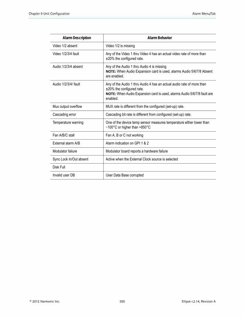
Chapter 9 Unit Configuration Alarm Menu/Tab
© 2012 Harmonic Inc. 300 Ellipse r.2.14, Revision A
Alarm Description Alarm Behavior
Video 1/2 absent Video 1/2 is missing
Video 1/2/3/4 fault Any of the Video 1 thru Video 4 has an actual video rate of more than ±20% the configured rate.
Audio 1/2/3/4 absent Any of the Audio 1 thru Audio 4 is missingNOTE: When Audio Expansion card is used, alarms Audio 5/6/7/8 Absent are enabled.
Audio 1/2/3/4/ fault Any of the Audio 1 thru Audio 4 has an actual audio rate of more than ±20% the configured rate.NOTE: When Audio Expansion card is used, alarms Audio 5/6/7/8 fault are enabled.
Mux output overflow MUX rate is different from the configured (set-up) rate.
Cascading error Cascading bit rate is different from configured (set-up) rate.
Temperature warning One of the device temp sensor measures temperature either lower than −100°C or higher than +850°C
Fan A/B/C stall Fan A, B or C not working
External alarm A/B Alarm indication on GPI 1 & 2
Modulator failure Modulator board reports a hardware failure
Sync Lock In/Out absent Active when the External Clock source is selected
Disk Full
Invalid user DB User Data Base corrupted
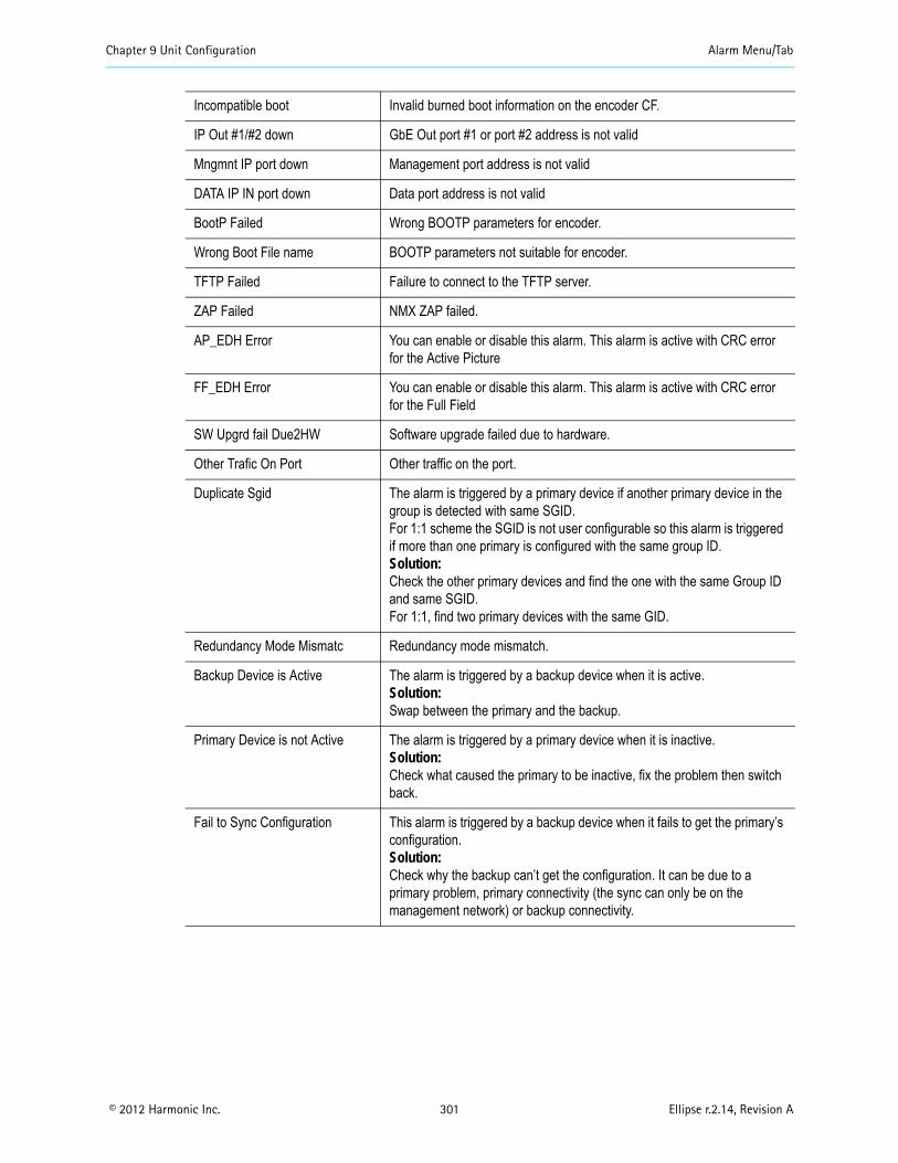
Chapter 9 Unit Configuration Alarm Menu/Tab
© 2012 Harmonic Inc. 301 Ellipse r.2.14, Revision A
Incompatible boot Invalid burned boot information on the encoder CF.
IP Out #1/#2 down GbE Out port #1 or port #2 address is not valid
Mngmnt IP port down Management port address is not valid
DATA IP IN port down Data port address is not valid
BootP Failed Wrong BOOTP parameters for encoder.
Wrong Boot File name BOOTP parameters not suitable for encoder.
TFTP Failed Failure to connect to the TFTP server.
ZAP Failed NMX ZAP failed.
AP_EDH Error You can enable or disable this alarm. This alarm is active with CRC error for the Active Picture
FF_EDH Error You can enable or disable this alarm. This alarm is active with CRC error for the Full Field
SW Upgrd fail Due2HW Software upgrade failed due to hardware.
Other Trafic On Port Other traffic on the port.
Duplicate Sgid The alarm is triggered by a primary device if another primary device in the group is detected with same SGID.For 1:1 scheme the SGID is not user configurable so this alarm is triggered if more than one primary is configured with the same group ID.Solution:Check the other primary devices and find the one with the same Group ID and same SGID.For 1:1, find two primary devices with the same GID.
Redundancy Mode Mismatc Redundancy mode mismatch.
Backup Device is Active The alarm is triggered by a backup device when it is active.Solution:Swap between the primary and the backup.
Primary Device is not Active The alarm is triggered by a primary device when it is inactive.Solution:Check what caused the primary to be inactive, fix the problem then switch back.
Fail to Sync Configuration This alarm is triggered by a backup device when it fails to get the primary’s configuration.Solution:Check why the backup can’t get the configuration. It can be due to a primary problem, primary connectivity (the sync can only be on the management network) or backup connectivity.
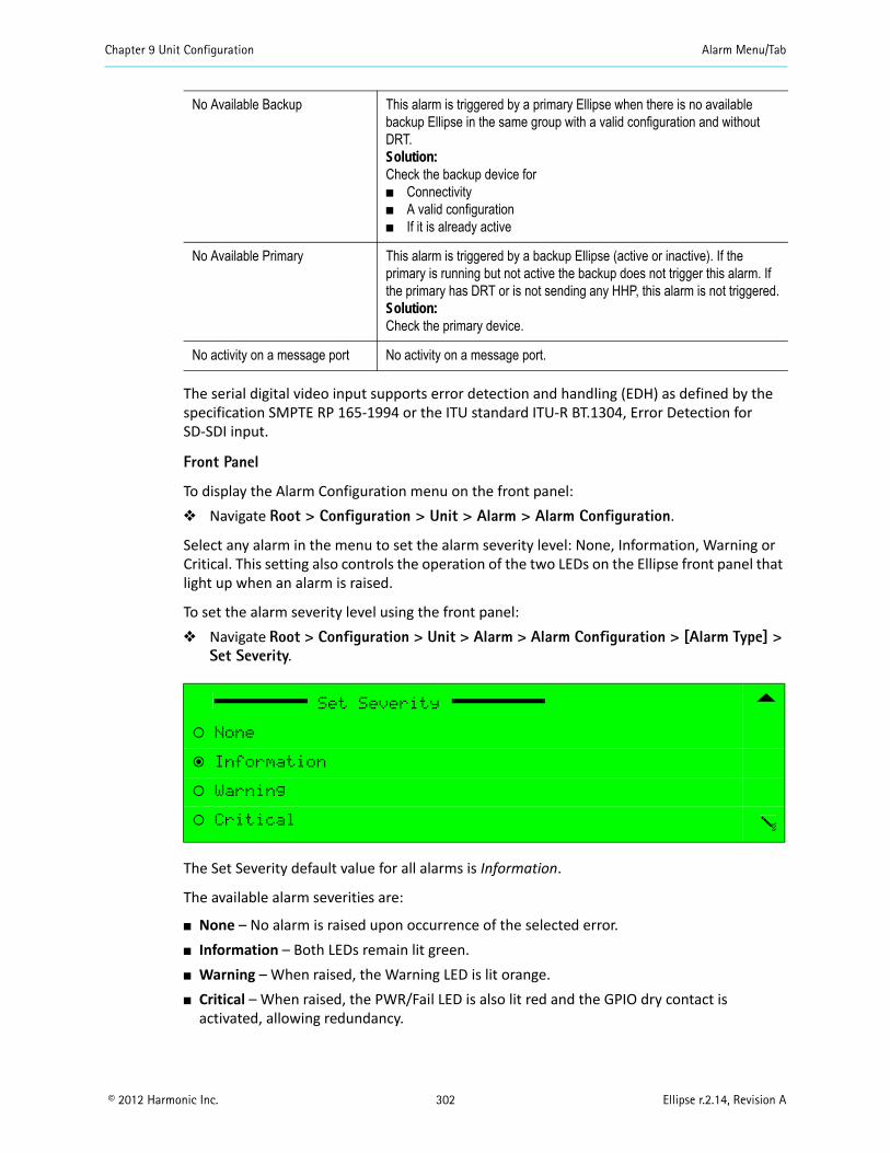
Chapter 9 Unit Configuration Alarm Menu/Tab
© 2012 Harmonic Inc. 302 Ellipse r.2.14, Revision A
The serial digital video input supports error detection and handling (EDH) as defined by the specification SMPTE RP 165-1994 or the ITU standard ITU-R BT.1304, Error Detection for SD-SDI input.
Front Panel
To display the Alarm Configuration menu on the front panel: Navigate Root > Configuration > Unit > Alarm > Alarm Configuration.
Select any alarm in the menu to set the alarm severity level: None, Information, Warning or Critical. This setting also controls the operation of the two LEDs on the Ellipse front panel that light up when an alarm is raised.
To set the alarm severity level using the front panel: Navigate Root > Configuration > Unit > Alarm > Alarm Configuration > [Alarm Type] >
Set Severity.
The Set Severity default value for all alarms is Information.
The available alarm severities are:
None – No alarm is raised upon occurrence of the selected error. Information – Both LEDs remain lit green. Warning – When raised, the Warning LED is lit orange. Critical – When raised, the PWR/Fail LED is also lit red and the GPIO dry contact is
activated, allowing redundancy.
No Available Backup This alarm is triggered by a primary Ellipse when there is no available backup Ellipse in the same group with a valid configuration and without DRT.Solution:Check the backup device for Connectivity A valid configuration If it is already active
No Available Primary This alarm is triggered by a backup Ellipse (active or inactive). If the primary is running but not active the backup does not trigger this alarm. If the primary has DRT or is not sending any HHP, this alarm is not triggered.Solution:Check the primary device.
No activity on a message port No activity on a message port.
Set Severity
‚ None
ƒ Information
‚ Warning
‚ Critical
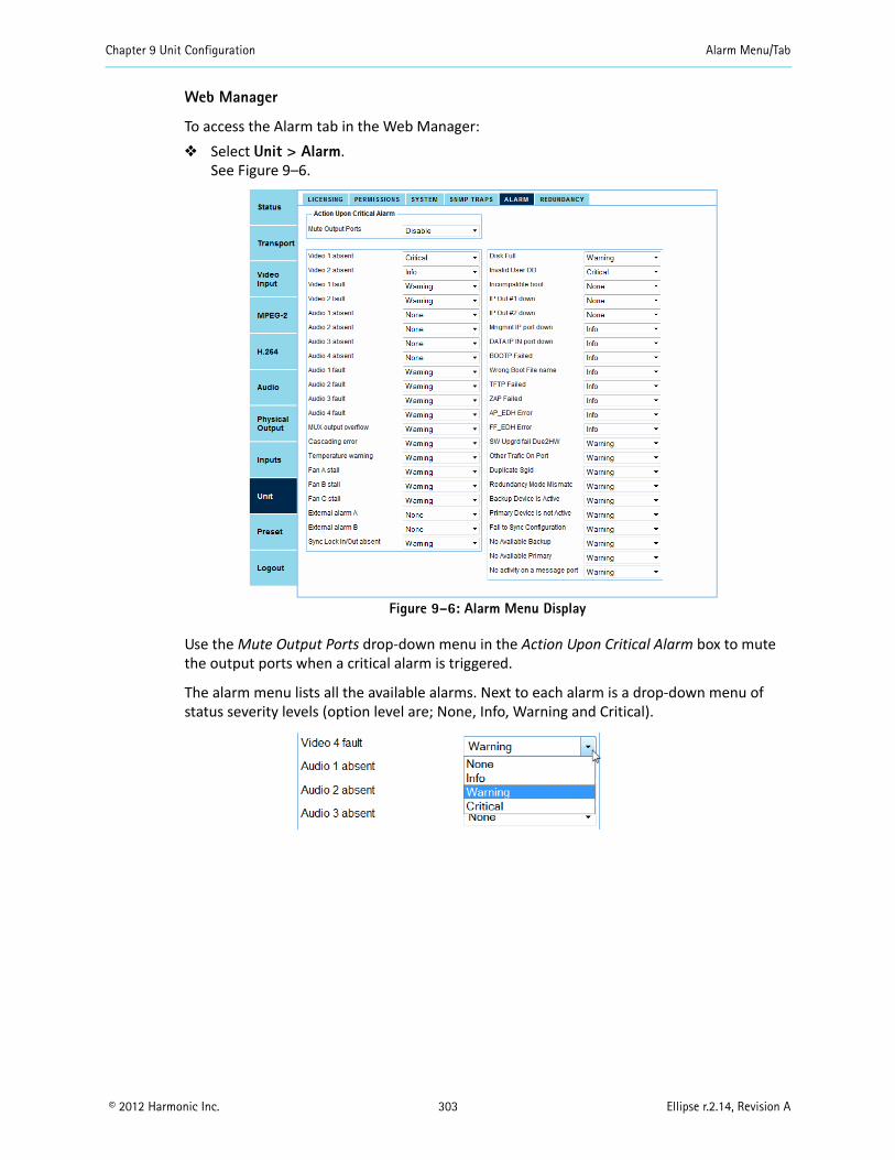
Chapter 9 Unit Configuration Alarm Menu/Tab
© 2012 Harmonic Inc. 303 Ellipse r.2.14, Revision A
Web Manager
To access the Alarm tab in the Web Manager: Select Unit > Alarm.
See Figure 9–6.
Figure 9–6: Alarm Menu Display
Use the Mute Output Ports drop-down menu in the Action Upon Critical Alarm box to mute the output ports when a critical alarm is triggered.
The alarm menu lists all the available alarms. Next to each alarm is a drop-down menu of status severity levels (option level are; None, Info, Warning and Critical).

Chapter 9 Unit Configuration Redundancy Menu/Tab
© 2012 Harmonic Inc. 304 Ellipse r.2.14, Revision A
9.6 Redundancy Menu/TabIn order to ensure the continuous transmission of video/data streams, transmitting networks employ various protection or redundancy options. Redundancy solutions are implemented where high availability is required. Redundancy solutions provide various levels of assurance (power supply versus device redundancy) and are application dependant.
This section discusses the redundancy solution that relates to device redundancy. The redundancy mechanism is basically a 1:1 device redundancy and it protects from severe failures and provides a high level of assurance.
The Ellipse 1000/2000 supports device 1:1 hot:warm redundancy. Use the redundancy menu/tab to configure device redundancy.
Primary and backup devices are connected via the management and MPE ports.
Automatic mode is the normal way of using redundancy. The primary Ellipse is active and the backup Ellipse is inactive. You can use many redundancy pairs by using a different group number for each pair. You can change the device mode but not the device state. At least one critical alarm must be set to use auto redundancy mode.
Automatic Mode
When a critical alarm is triggered, the backup Ellipse takes over from the primary Ellipse. You cannot change the redundancy mode for an inactive primary or for an active backup. In the cases of an inactive primary and an active backup, you first need to change the device roles so that the primary is the active and the backup is the inactive and change mode to None.
When using Automatic mode redundancy, the most common way to force a redundancy switch is to unplug the video input cable. The backup Ellipse automatically becomes active when the primary device has no video input, as long as you have a related input alarm configured as critical.
Manual Mode
You might manually perform a redundancy switch because:
You received notification of a service-affecting alarm on a primary device. An automatic redundancy switch occurred, and now you are ready to put the recovered
device back online. You want to take a device offline temporarily.
The redundancy parameters are:
Mode – The parameters are None, Manual and Automatic. The default is None. Device Role – The parameters are Primary and Backup. This device can be either the
primary or the backup. The backup device advertises the latest configuration. The backup device gets the most updated configuration from the primary device. Usually the backup device polls the configuration of the primary device once redundancy is applied and during operation to monitor for changes in the primary configuration. The default is Primary.
Multicast address – The same multicast address must be configured for both devices. The default is 225.000.000.001.
Multicast port – The range is 0–65535. The default is 12345. Group ID – Use the same group number for each redundancy pair. The range is 1–65535.
The default is 1.
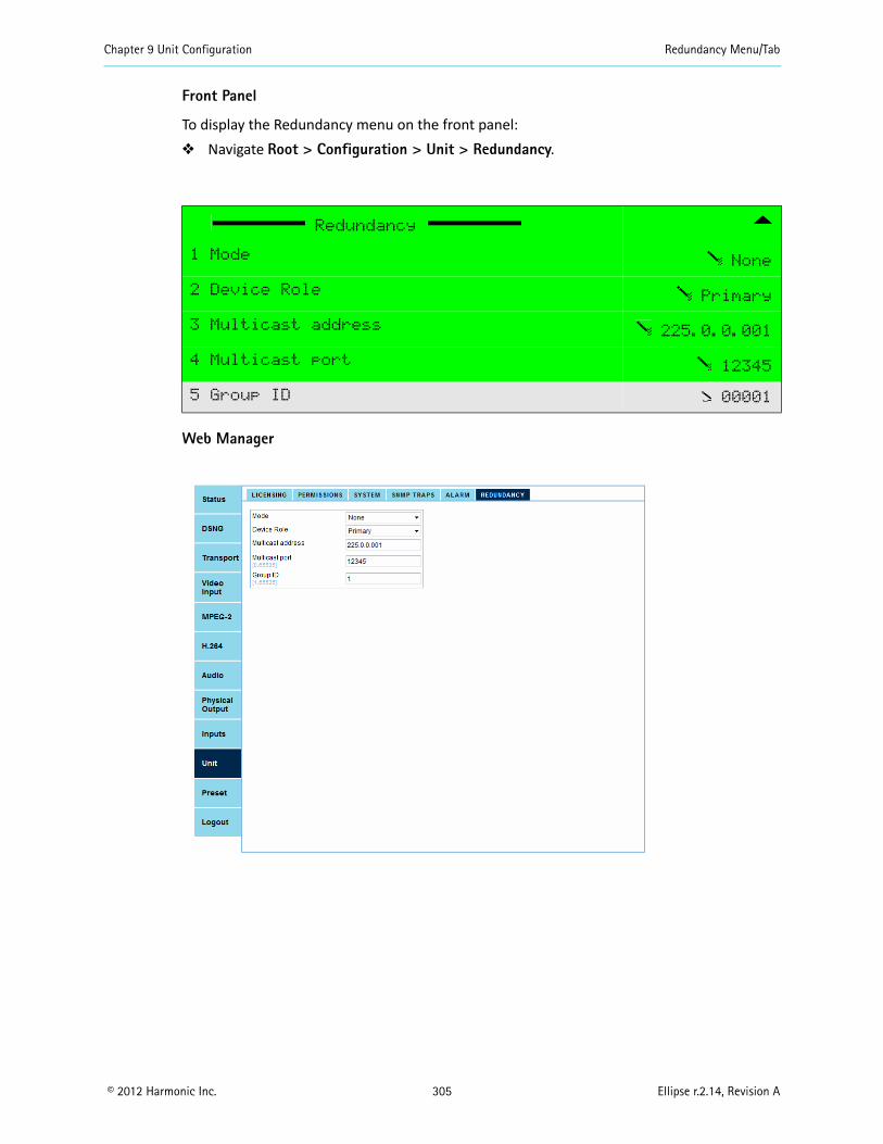
Chapter 9 Unit Configuration Redundancy Menu/Tab
© 2012 Harmonic Inc. 305 Ellipse r.2.14, Revision A
Front Panel
To display the Redundancy menu on the front panel: Navigate Root > Configuration > Unit > Redundancy.
Web Manager
Redundancy
1 Mode None
2 Device Role Primary
3 Multicast address 225.0.0.001
4 Multicast port 12345
5 Group ID 00001
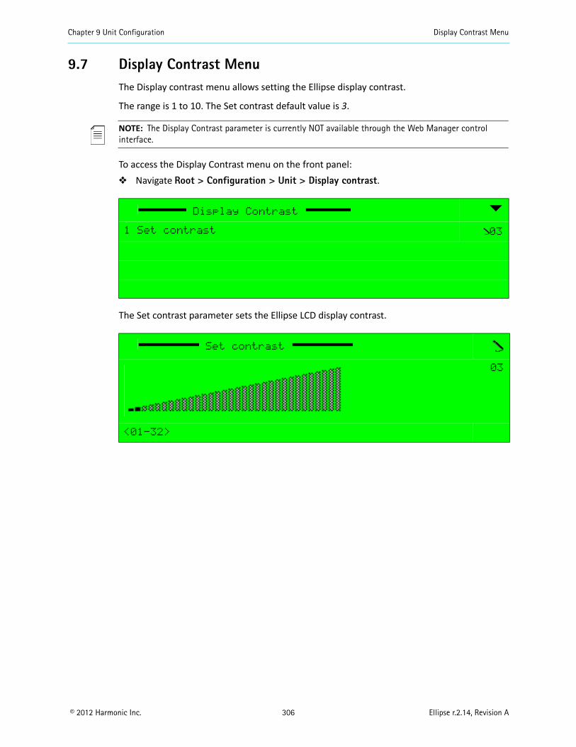
Chapter 9 Unit Configuration Display Contrast Menu
© 2012 Harmonic Inc. 306 Ellipse r.2.14, Revision A
9.7 Display Contrast MenuThe Display contrast menu allows setting the Ellipse display contrast.
The range is 1 to 10. The Set contrast default value is 3.
NOTE: The Display Contrast parameter is currently NOT available through the Web Manager control interface.
To access the Display Contrast menu on the front panel: Navigate Root > Configuration > Unit > Display contrast.
The Set contrast parameter sets the Ellipse LCD display contrast.
Display Contrast
1 Set contrast 03
Set contrast
03
<01-32>
© 2012 Harmonic Inc. 307 Ellipse r.2.14, Revision A
Chapter 10DSNG Configuration
This chapter details the DSNG Modulation and Up-Conversion configuration menus and parameters for the Ellipse 2000 DSNG Contribution Encoders.
Topics:
General
L-Band Modulator Parameters
IF Modulator Parameters
Common Modulation Parameters
10.1 GeneralThe DSNG Modulation and Up-Converter menu allows the user to set modulation and up-converting parameters for the encoders equipped with an MPEG-S/S2 DSNG modulator module. These DSNG dedicated Ellipse platforms provide IF or L-Band modulation and up-converting outputs for the encoder output streams.
Based on the modulation mode selected for the encoder, some of the parameters are unique for L-Band modulator and up-converter, some are unique for the IF modulator and some are common to both modulation schemes. Therefore, this chapter is divided into three sections (see Figure 10–1):
L-Band Modulator Parameters – Details the parameters unique to the L-Band modulator (see 10.2 L-Band Modulator Parameters).
IF Modulator Parameters – Details the parameters unique to the IF modulator (see 10.3 IF Modulator Parameters).
Common Modulation Parameters – Detailing the modulation parameters common for both IF and L-Band modulators (see 10.4 Common Modulation Parameters).
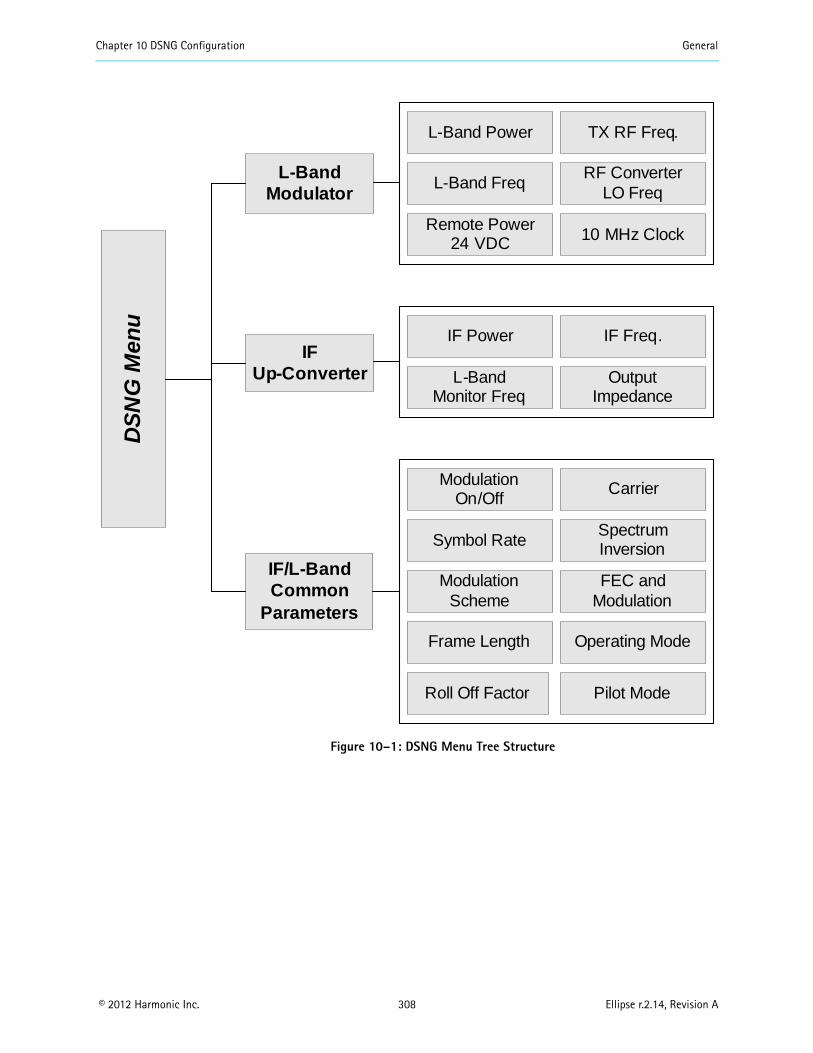
Chapter 10 DSNG Configuration General
© 2012 Harmonic Inc. 308 Ellipse r.2.14, Revision A
Figure 10–1: DSNG Menu Tree Structure
L-Band Modulator
IF/L-Band Common
Parameters
L-Band Power TX RF Freq.
IF Up-Converter
DS
NG
Men
u
L-Band FreqRF Converter
LO Freq
Remote Power24 VDC 10 MHz Clock
IF Power IF Freq.
L-Band Monitor Freq
Output Impedance
Modulation On/Off
Carrier
Symbol RateSpectrum Inversion
Modulation Scheme
FEC and Modulation
Frame Length Operating Mode
Roll Off Factor Pilot Mode
Chapter 10 DSNG Configuration L-Band Modulator Parameters
© 2012 Harmonic Inc. 309 Ellipse r.2.14, Revision A
10.2 L-Band Modulator ParametersThis group of parameters sets the L-Band modulator configuration.
Some of these parameters are unique L-Band modulator parameters and are detailed in the following sub-paragraphs: Carrier parameter, see 10.2.1 Carrier. L-Band Power parameter, see 10.2.2 L-Band Power. Reduced L-Band Power, see 10.2.3 Reduced L-Band Power. TX RF Frequency parameter, see 10.2.4 TX RF Frequency. RF Conv. LO Frequency parameter, see 10.2.5 RF Conv. LO Frequency. L-Band Frequency parameter, see 10.2.6 L-Band Frequency. Remote Power 24 VDC parameter, see 10.2.7 Remote Power 24 VDC. 10 MHz Clock parameter, see 10.2.8 10 MHz Clock.
NOTE: This set of parameters is not available for IF modulator units. All other parameters are common to both modulation schemes and are detailed in 10.4 Common Modulation Parameters on page 322.
The common modulation parameters are detailed in the following sub-paragraphs: Modulation On/Off parameter, see 10.4.1 Modulation On/Off. Symbol Rate parameter, see 10.4.2 Symbol Rate. Spectrum Inversion parameter, see 10.4.3 Spectrum Inversion. Modulation Scheme parameter, see 10.4.4 Modulation Scheme. FEC and Modulation parameter, see 10.4.5 FEC and Modulation. Frame Length parameter, see 10.4.6 Frame Length. Operating Mode parameter, see 10.4.7 Operating Mode. Roll-Off Factor parameter, see 10.4.8 Roll-Off Factor. Pilot Mode parameter, see 10.4.9 Pilot Mode.

Chapter 10 DSNG Configuration L-Band Modulator Parameters
© 2012 Harmonic Inc. 310 Ellipse r.2.14, Revision A
Front Panel
To access the L-Band Modulation and Up-Converter menu on the front panel: Navigate Root > L-Band Modulation & Up-Converter.
L-Band Modulation & Up-converter
Carrier On
L-Band Power -20
Reduced L-Band Power -13.0
Modulation on/off Off
Symbol Rate 10000000
TX RF Freq 014950000
RF Conv. LO Freq 014000000
L-Band Frequency 0950000
Spectrum Inversion Direct
Modulation Scheme DVB-S2
FEC and Modulation QPSK 2/3
Frame Length 64800 bits
Operating Mode C and M Restore...
Roll-Off Factor 0.35
Pilot Mode Off
Remote Power 24VDC Off
10MHz Clock Off
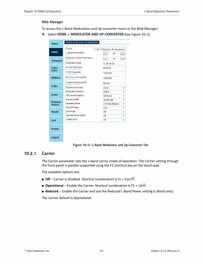
Chapter 10 DSNG Configuration L-Band Modulator Parameters
© 2012 Harmonic Inc. 311 Ellipse r.2.14, Revision A
Web Manager
To access the L-Band Modulation and Up-converter menu in the Web Manager: Select DSNG > MODULATOR AND UP-CONVERTER (see Figure 10–2).
Figure 10–2: L-Band Modulator and Up-Converter Tab
10.2.1 Carrier
The Carrier parameter sets the L-band carrier mode of operation. The Carrier setting through the front panel is parallel supported using the F2 shortcut key on the touch-pad.
The available options are:
Off – Carrier is disabled. Shortcut combination is F2 + Right .
Operational – Enable the Carrier. Shortcut combination is F2 + Up . Reduced – Enable the Carrier and use the Reduced L-Band Power setting (L-Band only).
The Carrier default is Operational.
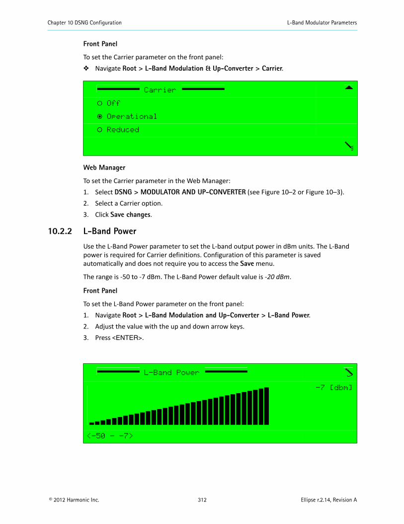
Chapter 10 DSNG Configuration L-Band Modulator Parameters
© 2012 Harmonic Inc. 312 Ellipse r.2.14, Revision A
Front Panel
To set the Carrier parameter on the front panel: Navigate Root > L-Band Modulation & Up-Converter > Carrier.
Web Manager
To set the Carrier parameter in the Web Manager:1. Select DSNG > MODULATOR AND UP-CONVERTER (see Figure 10–2 or Figure 10–3).2. Select a Carrier option.3. Click Save changes.
10.2.2 L-Band Power
Use the L-Band Power parameter to set the L-band output power in dBm units. The L-Band power is required for Carrier definitions. Configuration of this parameter is saved automatically and does not require you to access the Save menu.
The range is -50 to -7 dBm. The L-Band Power default value is -20 dBm.
Front Panel
To set the L-Band Power parameter on the front panel:1. Navigate Root > L-Band Modulation and Up-Converter > L-Band Power.2. Adjust the value with the up and down arrow keys.3. Press <ENTER>.
Carrier
‚ Off
ƒ Operational
‚ Reduced
L-Band Power
-7 [dbm]
<-50 - -7>
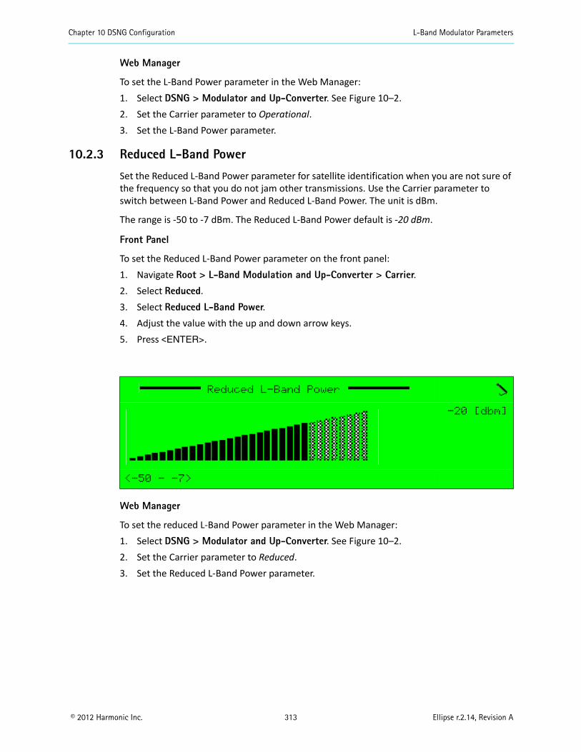
Chapter 10 DSNG Configuration L-Band Modulator Parameters
© 2012 Harmonic Inc. 313 Ellipse r.2.14, Revision A
Web Manager
To set the L-Band Power parameter in the Web Manager:1. Select DSNG > Modulator and Up-Converter. See Figure 10–2.2. Set the Carrier parameter to Operational.3. Set the L-Band Power parameter.
10.2.3 Reduced L-Band Power
Set the Reduced L-Band Power parameter for satellite identification when you are not sure of the frequency so that you do not jam other transmissions. Use the Carrier parameter to switch between L-Band Power and Reduced L-Band Power. The unit is dBm.
The range is -50 to -7 dBm. The Reduced L-Band Power default is -20 dBm.
Front Panel
To set the Reduced L-Band Power parameter on the front panel:1. Navigate Root > L-Band Modulation and Up-Converter > Carrier.2. Select Reduced.3. Select Reduced L-Band Power.4. Adjust the value with the up and down arrow keys.5. Press <ENTER>.
Web Manager
To set the reduced L-Band Power parameter in the Web Manager:1. Select DSNG > Modulator and Up-Converter. See Figure 10–2.2. Set the Carrier parameter to Reduced.3. Set the Reduced L-Band Power parameter.
Reduced L-Band Power
-20 [dbm]
<-50 - -7>

Chapter 10 DSNG Configuration L-Band Modulator Parameters
© 2012 Harmonic Inc. 314 Ellipse r.2.14, Revision A
10.2.4 TX RF Frequency
The TX RF Freq (frequency) parameter creates the connection between the LO frequency and the L-Band. This determines the actual rate sent from the upconverter module. The actual value is calculated according to the RF Conv. LO Frequency value and the L-Band Frequency value.
Any changes to the TX RF Frequency parameter’s value affect the L-Band Frequency parameter’s value, matching it to the calculated value. For example, when changing the TX RF Frequency from 14,950,000 to 15,000,000 the following value changes occur:
NOTE: Changes to the TX RF Frequency value only affect the L-Band Frequency value. However, the RF Conv. LO Frequency can be configured manually by the user.
Front Panel
To set the TX RF Frequency parameter on the front panel: Navigate Root > L-Band Modulation and Up-Converter > TX RF Freq.
The range is 0 to 100,000,000 kHz. The TX RF Frequency default value is 15,000,000 kHz.
Web Manager
To set the TX RF Frequency parameter in the Web Manager: Select DSNG > Modulator and Up-Converter (see Figure 10–2).
Parameter Former Value New Value Change happens:
TX RF Freq 14,950,000 15,000,000 Manual
RF Conv. LO Freq 14,000,000 14,000,000 Keeps value
L-Band Freq 950,000 1,000,000 Automatic
TX RF Frequency
+014950000 [kHz]
<000000000 - +100000000>
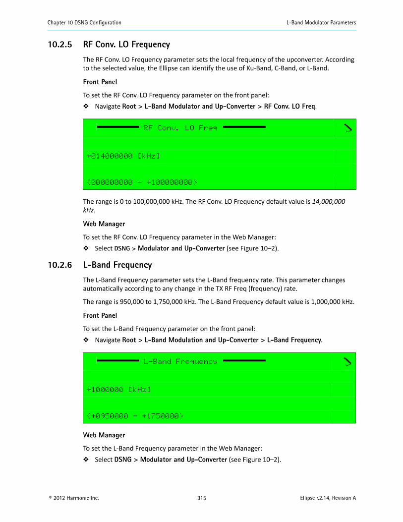
Chapter 10 DSNG Configuration L-Band Modulator Parameters
© 2012 Harmonic Inc. 315 Ellipse r.2.14, Revision A
10.2.5 RF Conv. LO Frequency
The RF Conv. LO Frequency parameter sets the local frequency of the upconverter. According to the selected value, the Ellipse can identify the use of Ku-Band, C-Band, or L-Band.
Front Panel
To set the RF Conv. LO Frequency parameter on the front panel: Navigate Root > L-Band Modulator and Up-Converter > RF Conv. LO Freq.
The range is 0 to 100,000,000 kHz. The RF Conv. LO Frequency default value is 14,000,000 kHz.
Web Manager
To set the RF Conv. LO Frequency parameter in the Web Manager: Select DSNG > Modulator and Up-Converter (see Figure 10–2).
10.2.6 L-Band Frequency
The L-Band Frequency parameter sets the L-Band frequency rate. This parameter changes automatically according to any change in the TX RF Freq (frequency) rate.
The range is 950,000 to 1,750,000 kHz. The L-Band Frequency default value is 1,000,000 kHz.
Front Panel
To set the L-Band Frequency parameter on the front panel: Navigate Root > L-Band Modulation and Up-Converter > L-Band Frequency.
Web Manager
To set the L-Band Frequency parameter in the Web Manager: Select DSNG > Modulator and Up-Converter (see Figure 10–2).
RF Conv. LO Freq
+014000000 [kHz]
<000000000 - +100000000>
L-Band Frequency
+1000000 [kHz]
<+0950000 - +1750000>
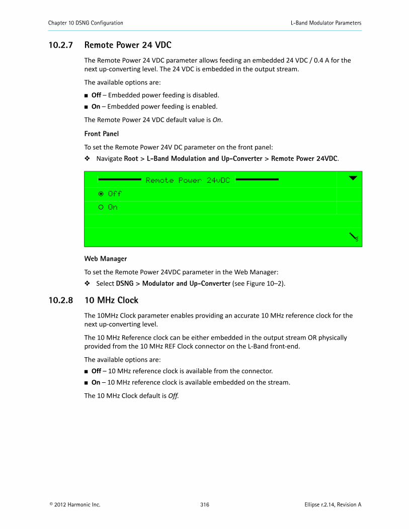
Chapter 10 DSNG Configuration L-Band Modulator Parameters
© 2012 Harmonic Inc. 316 Ellipse r.2.14, Revision A
10.2.7 Remote Power 24 VDC
The Remote Power 24 VDC parameter allows feeding an embedded 24 VDC / 0.4 A for the next up-converting level. The 24 VDC is embedded in the output stream.
The available options are:
Off – Embedded power feeding is disabled. On – Embedded power feeding is enabled.
The Remote Power 24 VDC default value is On.
Front Panel
To set the Remote Power 24V DC parameter on the front panel: Navigate Root > L-Band Modulation and Up-Converter > Remote Power 24VDC.
Web Manager
To set the Remote Power 24VDC parameter in the Web Manager: Select DSNG > Modulator and Up-Converter (see Figure 10–2).
10.2.8 10 MHz Clock
The 10MHz Clock parameter enables providing an accurate 10 MHz reference clock for the next up-converting level.
The 10 MHz Reference clock can be either embedded in the output stream OR physically provided from the 10 MHz REF Clock connector on the L-Band front-end.
The available options are: Off – 10 MHz reference clock is available from the connector. On – 10 MHz reference clock is available embedded on the stream.
The 10 MHz Clock default is Off.
Remote Power 24vDC
ƒ Off
‚ On
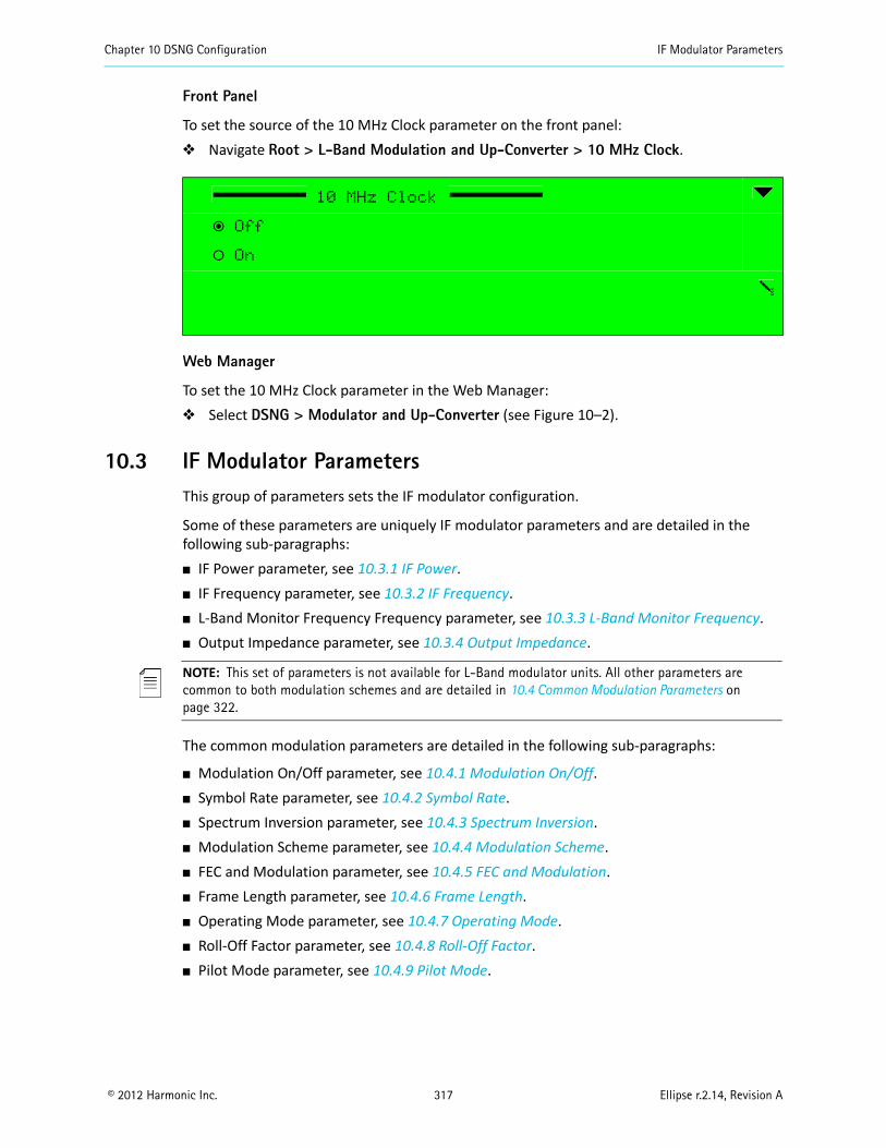
Chapter 10 DSNG Configuration IF Modulator Parameters
© 2012 Harmonic Inc. 317 Ellipse r.2.14, Revision A
Front Panel
To set the source of the 10 MHz Clock parameter on the front panel: Navigate Root > L-Band Modulation and Up-Converter > 10 MHz Clock.
Web Manager
To set the 10 MHz Clock parameter in the Web Manager: Select DSNG > Modulator and Up-Converter (see Figure 10–2).
10.3 IF Modulator ParametersThis group of parameters sets the IF modulator configuration.
Some of these parameters are uniquely IF modulator parameters and are detailed in the following sub-paragraphs: IF Power parameter, see 10.3.1 IF Power. IF Frequency parameter, see 10.3.2 IF Frequency. L-Band Monitor Frequency Frequency parameter, see 10.3.3 L-Band Monitor Frequency. Output Impedance parameter, see 10.3.4 Output Impedance.
NOTE: This set of parameters is not available for L-Band modulator units. All other parameters are common to both modulation schemes and are detailed in 10.4 Common Modulation Parameters on page 322.
The common modulation parameters are detailed in the following sub-paragraphs:
Modulation On/Off parameter, see 10.4.1 Modulation On/Off. Symbol Rate parameter, see 10.4.2 Symbol Rate. Spectrum Inversion parameter, see 10.4.3 Spectrum Inversion. Modulation Scheme parameter, see 10.4.4 Modulation Scheme. FEC and Modulation parameter, see 10.4.5 FEC and Modulation. Frame Length parameter, see 10.4.6 Frame Length. Operating Mode parameter, see 10.4.7 Operating Mode. Roll-Off Factor parameter, see 10.4.8 Roll-Off Factor. Pilot Mode parameter, see 10.4.9 Pilot Mode.
10 MHz Clock
ƒ Off
‚ On
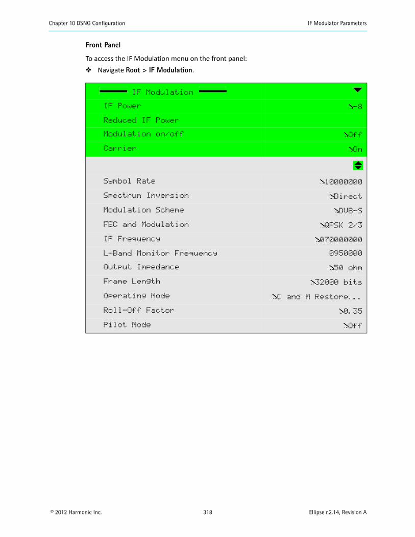
Chapter 10 DSNG Configuration IF Modulator Parameters
© 2012 Harmonic Inc. 318 Ellipse r.2.14, Revision A
Front Panel
To access the IF Modulation menu on the front panel: Navigate Root > IF Modulation.
IF Modulation
IF Power -8
Reduced IF Power
Modulation on/off Off
Carrier On
Symbol Rate 10000000
Spectrum Inversion Direct
Modulation Scheme DVB-S
FEC and Modulation QPSK 2/3
IF Frequency 070000000
L-Band Monitor Frequency 0950000
Output Impedance 50 ohm
Frame Length 32000 bits
Operating Mode C and M Restore...
Roll-Off Factor 0.35
Pilot Mode Off
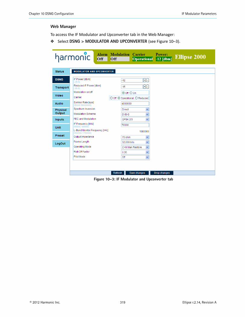
Chapter 10 DSNG Configuration IF Modulator Parameters
© 2012 Harmonic Inc. 319 Ellipse r.2.14, Revision A
Web Manager
To access the IF Modulator and Upconverter tab in the Web Manager: Select DSNG > MODULATOR AND UPCONVERTER (see Figure 10–3).
Figure 10–3: IF Modulator and Upconverter tab
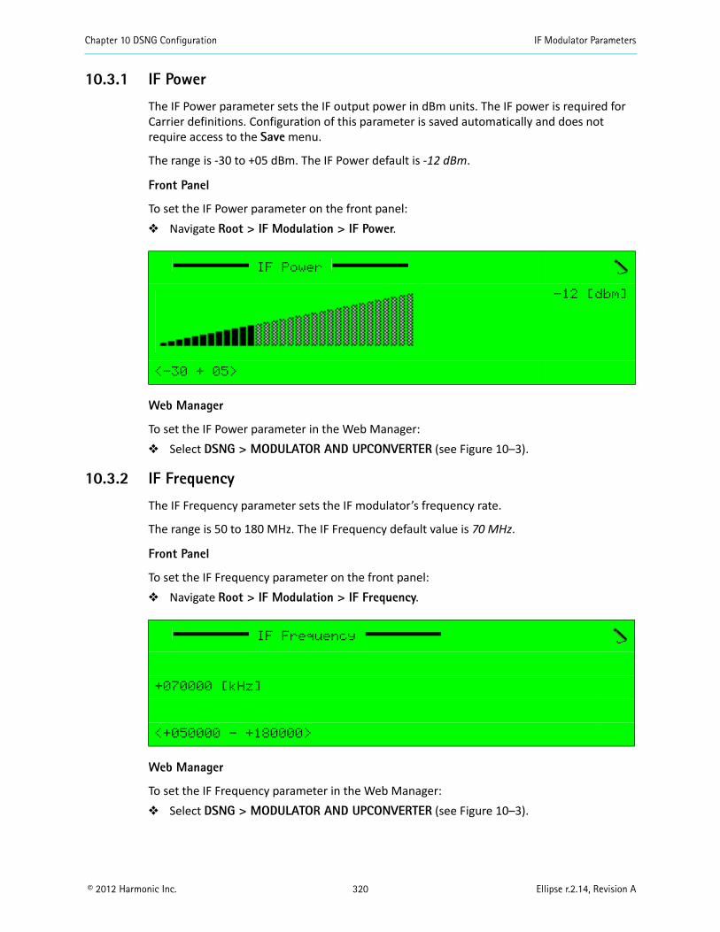
Chapter 10 DSNG Configuration IF Modulator Parameters
© 2012 Harmonic Inc. 320 Ellipse r.2.14, Revision A
10.3.1 IF Power
The IF Power parameter sets the IF output power in dBm units. The IF power is required for Carrier definitions. Configuration of this parameter is saved automatically and does not require access to the Save menu.
The range is -30 to +05 dBm. The IF Power default is -12 dBm.
Front Panel
To set the IF Power parameter on the front panel: Navigate Root > IF Modulation > IF Power.
Web Manager
To set the IF Power parameter in the Web Manager: Select DSNG > MODULATOR AND UPCONVERTER (see Figure 10–3).
10.3.2 IF Frequency
The IF Frequency parameter sets the IF modulator’s frequency rate.
The range is 50 to 180 MHz. The IF Frequency default value is 70 MHz.
Front Panel
To set the IF Frequency parameter on the front panel: Navigate Root > IF Modulation > IF Frequency.
Web Manager
To set the IF Frequency parameter in the Web Manager: Select DSNG > MODULATOR AND UPCONVERTER (see Figure 10–3).
IF Power
-12 [dbm]
<-30 + 05>
IF Frequency
+070000 [kHz]
<+050000 - +180000>
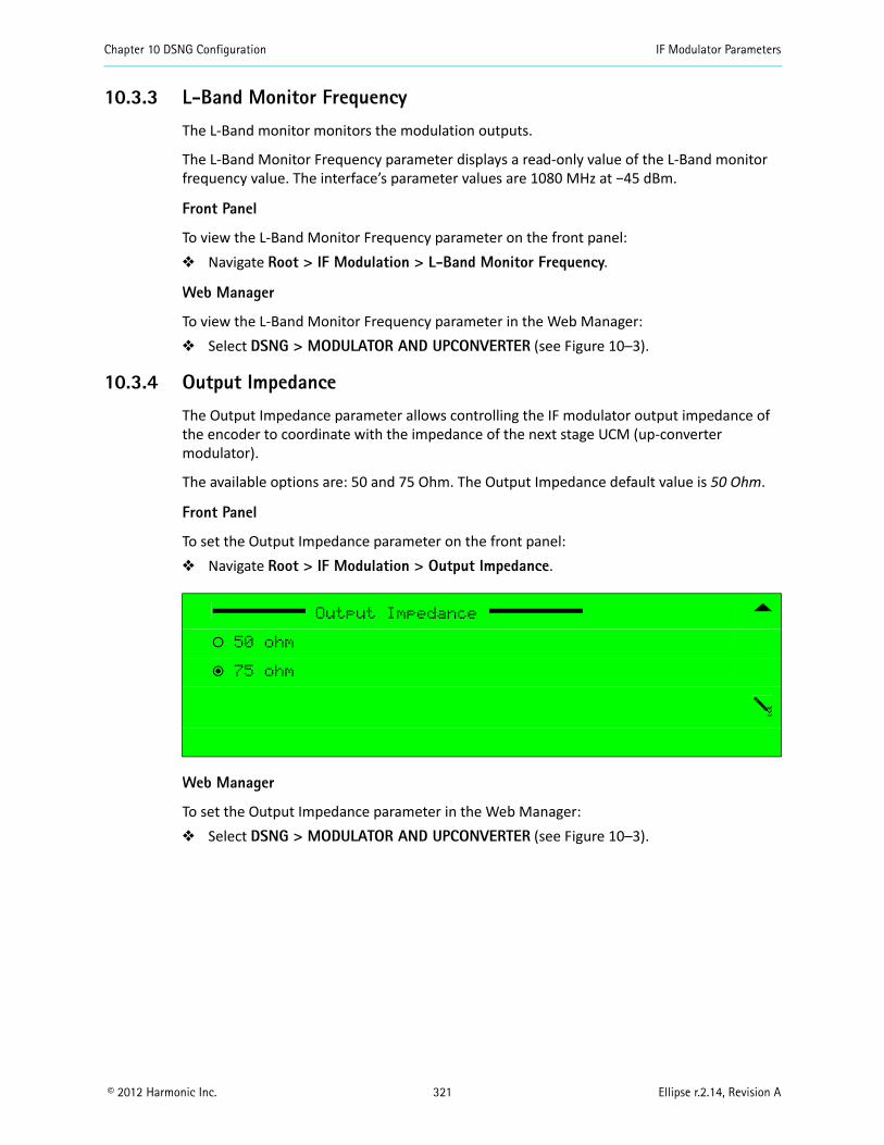
Chapter 10 DSNG Configuration IF Modulator Parameters
© 2012 Harmonic Inc. 321 Ellipse r.2.14, Revision A
10.3.3 L-Band Monitor Frequency
The L-Band monitor monitors the modulation outputs.
The L-Band Monitor Frequency parameter displays a read-only value of the L-Band monitor frequency value. The interface’s parameter values are 1080 MHz at −45 dBm.
Front Panel
To view the L-Band Monitor Frequency parameter on the front panel: Navigate Root > IF Modulation > L-Band Monitor Frequency.
Web Manager
To view the L-Band Monitor Frequency parameter in the Web Manager: Select DSNG > MODULATOR AND UPCONVERTER (see Figure 10–3).
10.3.4 Output Impedance
The Output Impedance parameter allows controlling the IF modulator output impedance of the encoder to coordinate with the impedance of the next stage UCM (up-converter modulator).
The available options are: 50 and 75 Ohm. The Output Impedance default value is 50 Ohm.
Front Panel
To set the Output Impedance parameter on the front panel: Navigate Root > IF Modulation > Output Impedance.
Web Manager
To set the Output Impedance parameter in the Web Manager: Select DSNG > MODULATOR AND UPCONVERTER (see Figure 10–3).
Output Impedance
‚ 50 ohm
ƒ 75 ohm
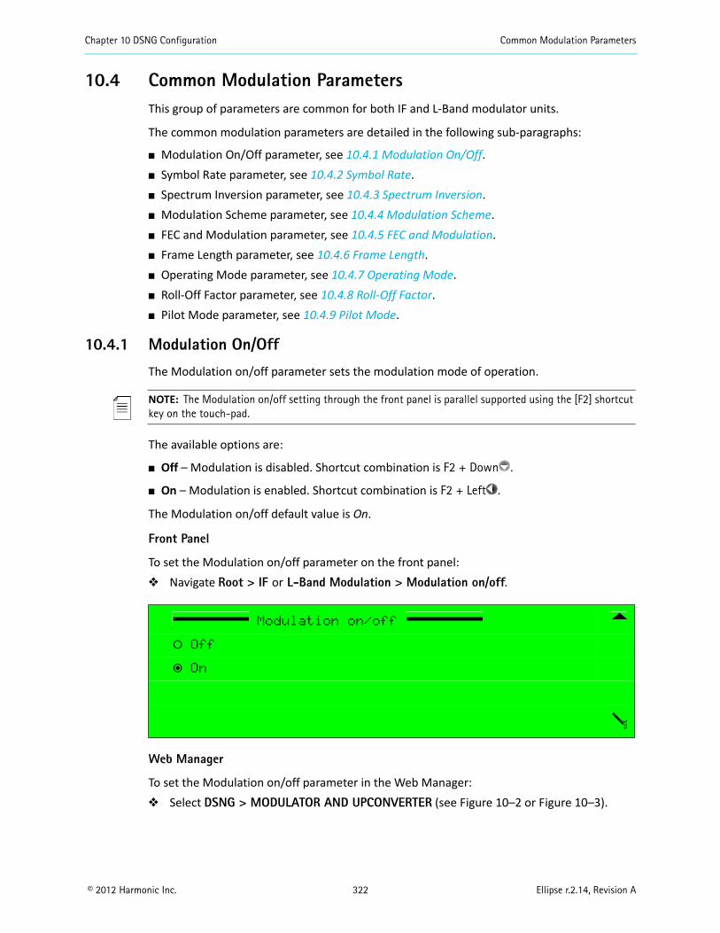
Chapter 10 DSNG Configuration Common Modulation Parameters
© 2012 Harmonic Inc. 322 Ellipse r.2.14, Revision A
10.4 Common Modulation ParametersThis group of parameters are common for both IF and L-Band modulator units.
The common modulation parameters are detailed in the following sub-paragraphs:
Modulation On/Off parameter, see 10.4.1 Modulation On/Off. Symbol Rate parameter, see 10.4.2 Symbol Rate. Spectrum Inversion parameter, see 10.4.3 Spectrum Inversion. Modulation Scheme parameter, see 10.4.4 Modulation Scheme. FEC and Modulation parameter, see 10.4.5 FEC and Modulation. Frame Length parameter, see 10.4.6 Frame Length. Operating Mode parameter, see 10.4.7 Operating Mode. Roll-Off Factor parameter, see 10.4.8 Roll-Off Factor. Pilot Mode parameter, see 10.4.9 Pilot Mode.
10.4.1 Modulation On/Off
The Modulation on/off parameter sets the modulation mode of operation.
NOTE: The Modulation on/off setting through the front panel is parallel supported using the [F2] shortcut key on the touch-pad.
The available options are:
Off – Modulation is disabled. Shortcut combination is F2 + Down .
On – Modulation is enabled. Shortcut combination is F2 + Left .
The Modulation on/off default value is On.
Front Panel
To set the Modulation on/off parameter on the front panel: Navigate Root > IF or L-Band Modulation > Modulation on/off.
Web Manager
To set the Modulation on/off parameter in the Web Manager: Select DSNG > MODULATOR AND UPCONVERTER (see Figure 10–2 or Figure 10–3).
Modulation on/off
‚ Off
ƒ On
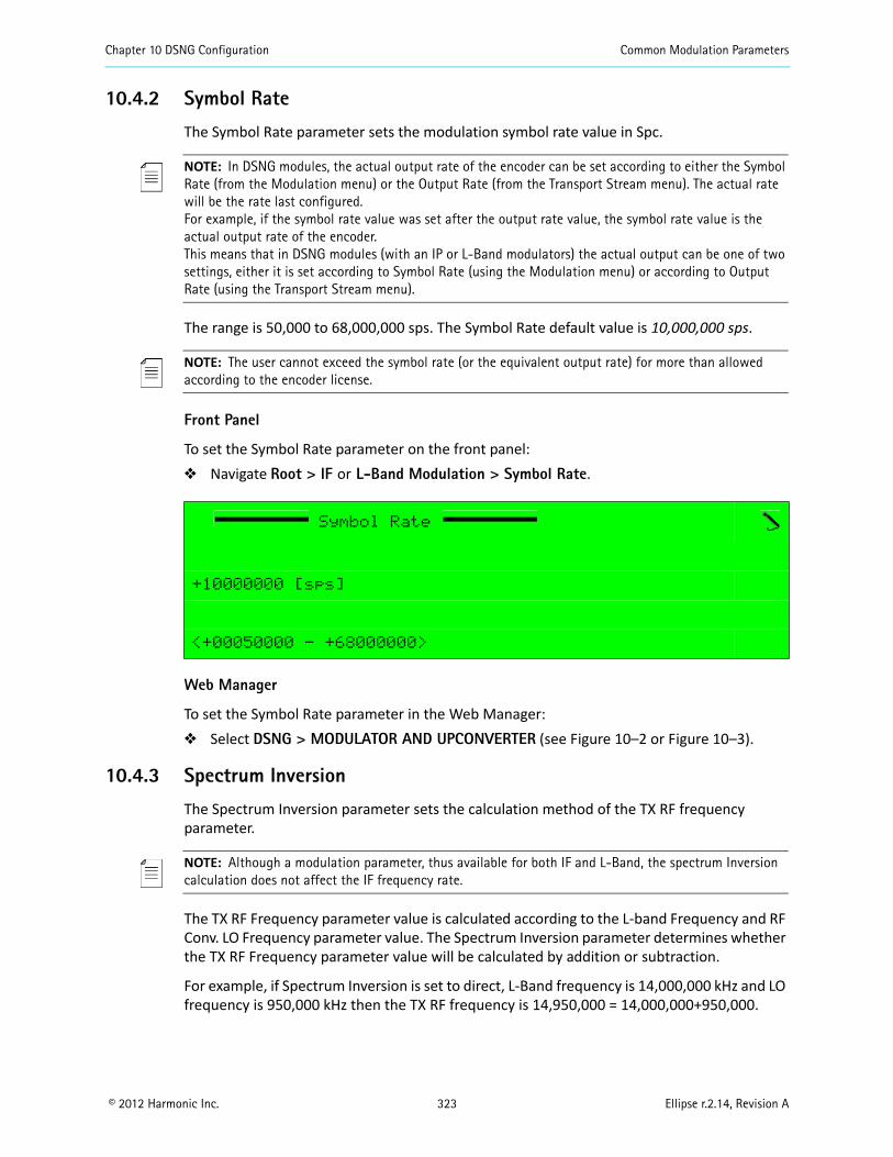
Chapter 10 DSNG Configuration Common Modulation Parameters
© 2012 Harmonic Inc. 323 Ellipse r.2.14, Revision A
10.4.2 Symbol Rate
The Symbol Rate parameter sets the modulation symbol rate value in Spc.
NOTE: In DSNG modules, the actual output rate of the encoder can be set according to either the Symbol Rate (from the Modulation menu) or the Output Rate (from the Transport Stream menu). The actual rate will be the rate last configured.For example, if the symbol rate value was set after the output rate value, the symbol rate value is the actual output rate of the encoder.This means that in DSNG modules (with an IP or L-Band modulators) the actual output can be one of two settings, either it is set according to Symbol Rate (using the Modulation menu) or according to Output Rate (using the Transport Stream menu).
The range is 50,000 to 68,000,000 sps. The Symbol Rate default value is 10,000,000 sps.
NOTE: The user cannot exceed the symbol rate (or the equivalent output rate) for more than allowed according to the encoder license.
Front Panel
To set the Symbol Rate parameter on the front panel: Navigate Root > IF or L-Band Modulation > Symbol Rate.
Web Manager
To set the Symbol Rate parameter in the Web Manager: Select DSNG > MODULATOR AND UPCONVERTER (see Figure 10–2 or Figure 10–3).
10.4.3 Spectrum Inversion
The Spectrum Inversion parameter sets the calculation method of the TX RF frequency parameter.
NOTE: Although a modulation parameter, thus available for both IF and L-Band, the spectrum Inversion calculation does not affect the IF frequency rate.
The TX RF Frequency parameter value is calculated according to the L-band Frequency and RF Conv. LO Frequency parameter value. The Spectrum Inversion parameter determines whether the TX RF Frequency parameter value will be calculated by addition or subtraction.
For example, if Spectrum Inversion is set to direct, L-Band frequency is 14,000,000 kHz and LO frequency is 950,000 kHz then the TX RF frequency is 14,950,000 = 14,000,000+950,000.
Symbol Rate
+10000000 [sps]
<+00050000 - +68000000>
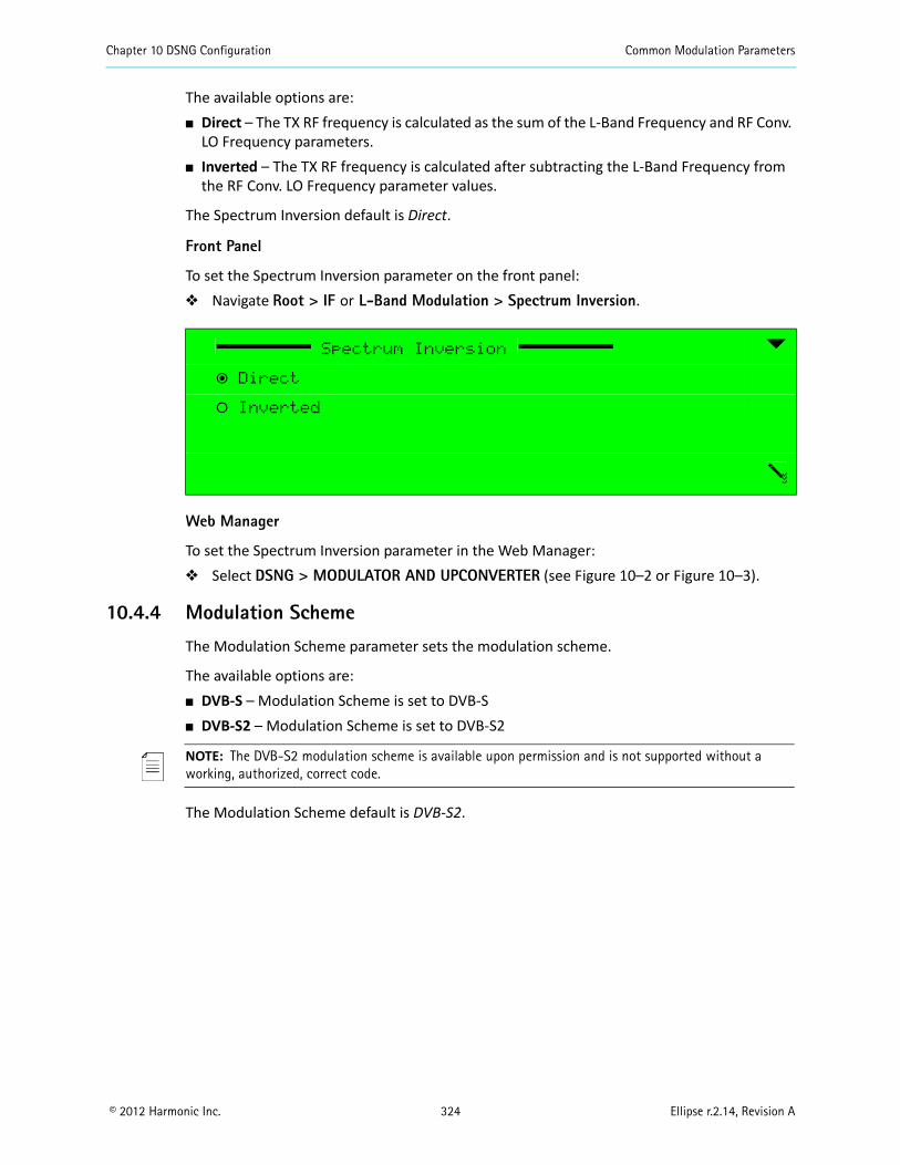
Chapter 10 DSNG Configuration Common Modulation Parameters
© 2012 Harmonic Inc. 324 Ellipse r.2.14, Revision A
The available options are: Direct – The TX RF frequency is calculated as the sum of the L-Band Frequency and RF Conv.
LO Frequency parameters. Inverted – The TX RF frequency is calculated after subtracting the L-Band Frequency from
the RF Conv. LO Frequency parameter values.
The Spectrum Inversion default is Direct.
Front Panel
To set the Spectrum Inversion parameter on the front panel: Navigate Root > IF or L-Band Modulation > Spectrum Inversion.
Web Manager
To set the Spectrum Inversion parameter in the Web Manager: Select DSNG > MODULATOR AND UPCONVERTER (see Figure 10–2 or Figure 10–3).
10.4.4 Modulation Scheme
The Modulation Scheme parameter sets the modulation scheme.
The available options are: DVB-S – Modulation Scheme is set to DVB-S DVB-S2 – Modulation Scheme is set to DVB-S2
NOTE: The DVB-S2 modulation scheme is available upon permission and is not supported without a working, authorized, correct code.
The Modulation Scheme default is DVB-S2.
Spectrum Inversion
ƒ Direct
‚ Inverted
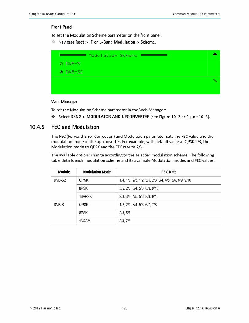
Chapter 10 DSNG Configuration Common Modulation Parameters
© 2012 Harmonic Inc. 325 Ellipse r.2.14, Revision A
Front Panel
To set the Modulation Scheme parameter on the front panel: Navigate Root > IF or L-Band Modulation > Scheme.
Web Manager
To set the Modulation Scheme parameter in the Web Manager: Select DSNG > MODULATOR AND UPCONVERTER (see Figure 10–2 or Figure 10–3).
10.4.5 FEC and Modulation
The FEC (Forward Error Correction) and Modulation parameter sets the FEC value and the modulation mode of the up-converter. For example, with default value at QPSK 2/3, the Modulation mode to QPSK and the FEC rate to 2/3.
The available options change according to the selected modulation scheme. The following table details each modulation scheme and its available Modulation modes and FEC values.
Modulation Scheme
‚ DVB-S
ƒ DVB-S2
Module Modulation Mode FEC Rate
DVB-S2 QPSK 1/4, 1/3, 2/5, 1/2, 3/5, 2/3, 3/4, 4/5, 5/6, 8/9, 9/10
8PSK 3/5, 2/3, 3/4, 5/6, 8/9, 9/10
16APSK 2/3, 3/4, 4/5, 5/6, 8/9, 9/10
DVB-S QPSK 1/2, 2/3, 3/4, 5/6, 6/7, 7/8
8PSK 2/3, 5/6
16QAM 3/4, 7/8
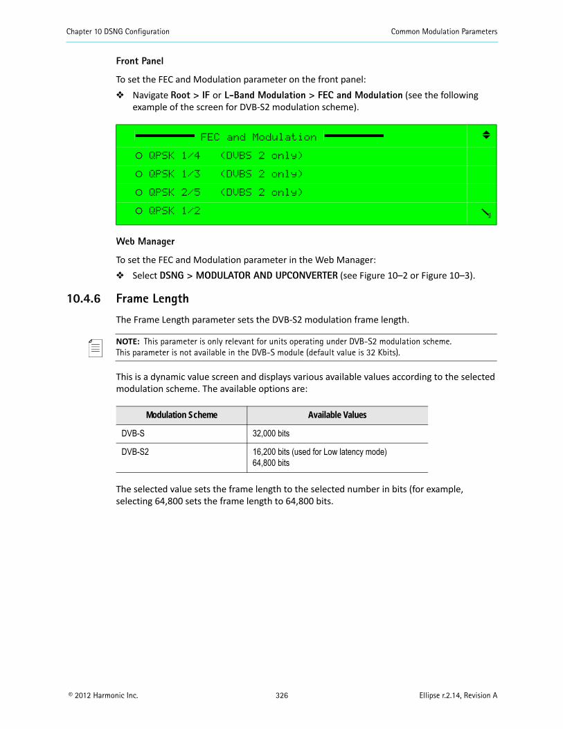
Chapter 10 DSNG Configuration Common Modulation Parameters
© 2012 Harmonic Inc. 326 Ellipse r.2.14, Revision A
Front Panel
To set the FEC and Modulation parameter on the front panel: Navigate Root > IF or L-Band Modulation > FEC and Modulation (see the following
example of the screen for DVB-S2 modulation scheme).
Web Manager
To set the FEC and Modulation parameter in the Web Manager: Select DSNG > MODULATOR AND UPCONVERTER (see Figure 10–2 or Figure 10–3).
10.4.6 Frame Length
The Frame Length parameter sets the DVB-S2 modulation frame length.
NOTE: This parameter is only relevant for units operating under DVB-S2 modulation scheme.This parameter is not available in the DVB-S module (default value is 32 Kbits).
This is a dynamic value screen and displays various available values according to the selected modulation scheme. The available options are:
The selected value sets the frame length to the selected number in bits (for example, selecting 64,800 sets the frame length to 64,800 bits.
FEC and Modulation
‚ QPSK 1/4 (DVBS 2 only)
‚ QPSK 1/3 (DVBS 2 only)
‚ QPSK 2/5 (DVBS 2 only)
‚ QPSK 1/2
Modulation Scheme Available Values
DVB-S 32,000 bits
DVB-S2 16,200 bits (used for Low latency mode)64,800 bits
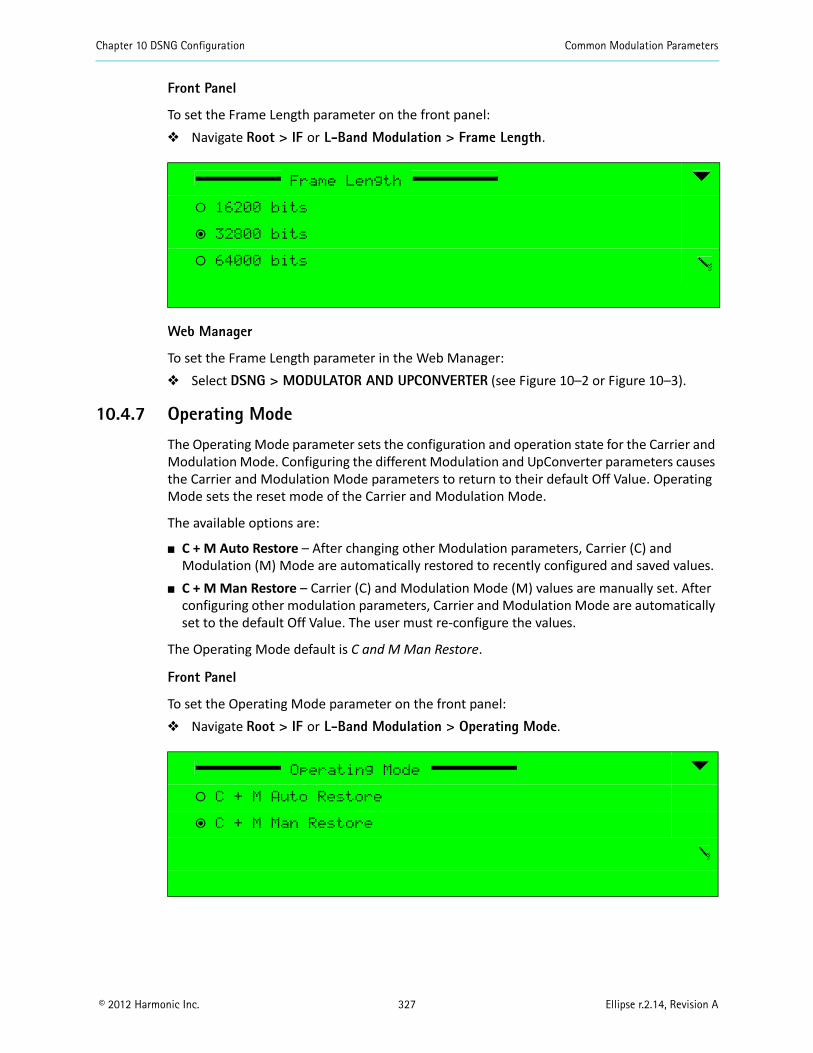
Chapter 10 DSNG Configuration Common Modulation Parameters
© 2012 Harmonic Inc. 327 Ellipse r.2.14, Revision A
Front Panel
To set the Frame Length parameter on the front panel: Navigate Root > IF or L-Band Modulation > Frame Length.
Web Manager
To set the Frame Length parameter in the Web Manager: Select DSNG > MODULATOR AND UPCONVERTER (see Figure 10–2 or Figure 10–3).
10.4.7 Operating Mode
The Operating Mode parameter sets the configuration and operation state for the Carrier and Modulation Mode. Configuring the different Modulation and UpConverter parameters causes the Carrier and Modulation Mode parameters to return to their default Off Value. Operating Mode sets the reset mode of the Carrier and Modulation Mode.
The available options are:
C + M Auto Restore – After changing other Modulation parameters, Carrier (C) and Modulation (M) Mode are automatically restored to recently configured and saved values.
C + M Man Restore – Carrier (C) and Modulation Mode (M) values are manually set. After configuring other modulation parameters, Carrier and Modulation Mode are automatically set to the default Off Value. The user must re-configure the values.
The Operating Mode default is C and M Man Restore.
Front Panel
To set the Operating Mode parameter on the front panel: Navigate Root > IF or L-Band Modulation > Operating Mode.
Frame Length
‚ 16200 bits
ƒ 32800 bits
‚ 64000 bits
Operating Mode
‚ C + M Auto Restore
ƒ C + M Man Restore
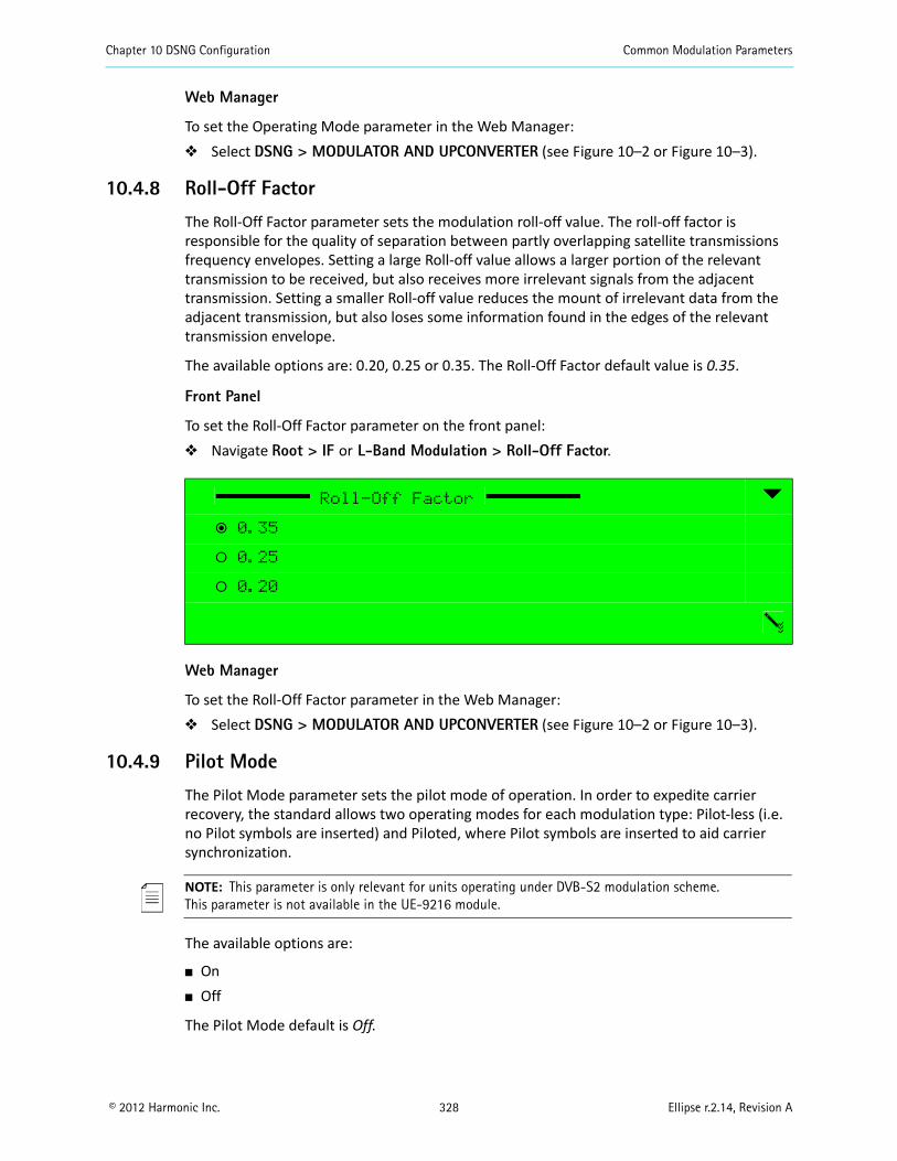
Chapter 10 DSNG Configuration Common Modulation Parameters
© 2012 Harmonic Inc. 328 Ellipse r.2.14, Revision A
Web Manager
To set the Operating Mode parameter in the Web Manager: Select DSNG > MODULATOR AND UPCONVERTER (see Figure 10–2 or Figure 10–3).
10.4.8 Roll-Off Factor
The Roll-Off Factor parameter sets the modulation roll-off value. The roll-off factor is responsible for the quality of separation between partly overlapping satellite transmissions frequency envelopes. Setting a large Roll-off value allows a larger portion of the relevant transmission to be received, but also receives more irrelevant signals from the adjacent transmission. Setting a smaller Roll-off value reduces the mount of irrelevant data from the adjacent transmission, but also loses some information found in the edges of the relevant transmission envelope.
The available options are: 0.20, 0.25 or 0.35. The Roll-Off Factor default value is 0.35.
Front Panel
To set the Roll-Off Factor parameter on the front panel: Navigate Root > IF or L-Band Modulation > Roll-Off Factor.
Web Manager
To set the Roll-Off Factor parameter in the Web Manager: Select DSNG > MODULATOR AND UPCONVERTER (see Figure 10–2 or Figure 10–3).
10.4.9 Pilot Mode
The Pilot Mode parameter sets the pilot mode of operation. In order to expedite carrier recovery, the standard allows two operating modes for each modulation type: Pilot-less (i.e. no Pilot symbols are inserted) and Piloted, where Pilot symbols are inserted to aid carrier synchronization.
NOTE: This parameter is only relevant for units operating under DVB-S2 modulation scheme.This parameter is not available in the UE-9216 module.
The available options are:
On Off
The Pilot Mode default is Off.
Roll-Off Factor
ƒ 0.35
‚ 0.25
‚ 0.20

Chapter 10 DSNG Configuration Common Modulation Parameters
© 2012 Harmonic Inc. 329 Ellipse r.2.14, Revision A
Front Panel
To set the Pilot Mode parameter on the front panel: Navigate Root > IF or L-Band Modulation > Pilot Mode.
Web Manager
To set the Pilot Mode parameter in the Web Manager: Select DSNG > MODULATOR AND UPCONVERTER (see Figure 10–2 or Figure 10–3).
Pilot Mode
ƒ Off
‚ On
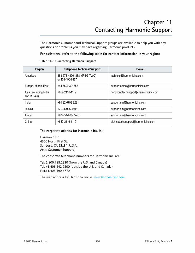
© 2012 Harmonic Inc. 330 Ellipse r.2.14, Revision A
Chapter 11Contacting Harmonic Support
The Harmonic Customer and Technical Support groups are available to help you with any questions or problems you may have regarding Harmonic products.
For assistance, refer to the following table for contact information in your region:
The corporate address for Harmonic Inc. is:
Harmonic Inc.4300 North First St.San Jose, CA 95134, U.S.A.Attn: Customer Support
The corporate telephone numbers for Harmonic Inc. are:
Tel. 1.800.788.1330 (from the U.S. and Canada)Tel. +1.408.542.2500 (outside the U.S. and Canada)Fax.+1.408.490.6770
The web address for Harmonic Inc. is www.harmonicinc.com.
Table 11–1: Contacting Harmonic Support
Region Telephone Technical Support E-mail
Americas 888-673-4896 (888-MPEG-TWO)or 408-490-6477
Europe, Middle East +44 7699 391552 [email protected]
Asia (excluding India and Russia)
+852-2116-1119 [email protected]
India +91 22 6793 9291 [email protected]
Russia +7 495 926 4608 [email protected]
Africa +972-54-900-7740 [email protected]
China +852-2116-1119 [email protected]
© 2012 Harmonic Inc. 331 Ellipse r.2.14, Revision A
Appendix ACharacteristics and Capabilities
A.1 Encoder InputsVideo Inputs: Video formats:
NTSC: M, J PAL: B,G, M
Input ports: CV and SD/HD-SDI
Port specifications: CV level: 1.0 Vpp SD/HD-SDI level: 800 mVpp CV impedance: 75Ω unbalanced SD/HD-SDI impedance: 75Ω unbalanced
Video Resolution: Horizontal SD:
MPEG-2: 720, 704, 640, 544, 528 (for NTSC only), 480, 368, 352 MPEG-4 AVC: 720, 640, 544, 528, 480, 352
Vertical SD: NTSC: 480, 240 PAL: 576, 288
High Definition (H.264): 1080ix1920, 1080ix1440, 1080ix960, 720px1280, 720px960 Interfaces:
SMPTE 259M for SD (SDI) SMPTE 292M for HD (SDI)
Aspect Ratio: 16:9 and 4:3 with auto mode
Audio Inputs: Input formats:
Analog AES/EBU Embedded
AES/EBU audio input:Impedance: 110 ± 2Ω
Appendix A Characteristics and Capabilities Encoder Outputs
© 2012 Harmonic Inc. 332 Ellipse r.2.14, Revision A
Analog audio input: Impedance: Balanced 600Ω / >13KΩ Selectable Level adjustment: 0 dBFS= -20 to +20 dBu (0.5dB steps)
Quantization: 24 bit (without compression)
DVB-ASI Input:
Built-in multiplexer for encoder cascading Passive loop-through for cascading redundancy Up to 50 Mbps
Sync Clock
Black Burst (CV) formats: PAL NTSC
Interface: ITU-R 624 Level: 1.0 Vpp Impedance: 75Ω unbalanced
A.2 Encoder OutputsDVB-ASI Outputs:
Physical line rate: 270 Mbps Output data rate: 350Kbps – 70 Mbps Impedance: 75±2Ω unbalanced Interface: Hot-Link
Dual GbE outputs: 100/1000 Base-T Auto Negotiation Output data rate: up to 70 Mbps Dual MPEGoIP output UDP/RTP protocols
A.3 Modulator Characteristics (Ellipse 2000)L-Band Output: QPSK per DVB-S (EN 300-421) Optional QPSK, 8PSK and 16QAM per DVB-DSNG (EN 210 301) Optional QPSK, 8PSK and 16APSK per DVB-S2 (EN 302 307) L-band output range: from 950 MHz to 1,750 MHz (50 Hz steps) Symbol rate range: from 50 Ksps to 15 Msps Roll Off at 20%, 25% and 35% Output power range: from -50 dBm to -7 dBm (0.5 dB steps)
Appendix A Characteristics and Capabilities Processing Capabilities
© 2012 Harmonic Inc. 333 Ellipse r.2.14, Revision A
Spurious level range: from -65 dBc at -10 dBm L-band monitoring output power: -45 dBm L-band monitoring output frequency: at current L-band transmit frequency Constant Code Rate Modulation (CCM) Supports Pilot Mode
External Block Up-Converter Support: DC Feed to BUC: up to 24 VDC at 0.4A controlled Selectable 10 MHz Reference clock (in-band or external)
IF Output: QPSK per DVB-S (EN 300-421) Optional QPSK, 8PSK and 16QAM per DVB-DSNG (EN 210 301) Optional QPSK, 8PSK and 16APSK per DVB-S2 (EN 302 307) IF output range: from 50 MHz to 180 MHz (1 kHz steps) Output power range: from -30 dBm to 5 dBm (0.5 dB steps) Selectable output impedance: 50Ω / 75Ω L-band monitoring output power: -45 dBm L-band monitoring output frequency: at 1080 MHz
A.4 Processing CapabilitiesVideo Processing:
Video encoding formats: MPEG-2 4:2:0 MP@ML MPEG-2 4:2:2 P@ML MPEG-4 AVC 4:2:0 MP@level3 MPEG-4 AVC 4:2:0 HP@level4
Video Latency Modes: Low Medium Normal/Standard Manual
Video encoding rates: 4:2:0: Up to 15 Mbps 4:2:2: From 4 Mbps up to 50 Mbps (Only for MPEG-2)
VBI Processing and support (SD at MPEG-2/MPEG-4 AVC): SDI and CV Inputs:
• TXX, WSS, VPS and TXT-Subtitling, VITC (only MPEG-2), CC (only MPEG-2)• CV Inputs: AMOL and TV Guide
Appendix A Characteristics and Capabilities Processing Capabilities
© 2012 Harmonic Inc. 334 Ellipse r.2.14, Revision A
Video Test Bar
Each video input supports the Broadcast Test Pattern (BAR signal emulation).
Audio Processing:
Audio encoding formats: MPEG-1 layer 2
Dolby® Digital1 2.0 Advanced Audio Coding – Low Complexity (MPEG-2 AAC LC) High Efficiency Advanced Audio Coding (MPEG-4 HE AAC) V1, V2
Audio Encoding rates: MPEG-1 Layer 2: 32 Kbps to 384 Kbps
Dolby® Digital1: 56 Kbps to 640 Kbps MPEG-2 AAC LC: 32 Kbps to 192 Kbps (stereo) MPEG-4 HE AAC: 10 Kbps to 72 Kbps
Sample Rate Converter (SRC) – Sampling Rates: 32 kHz, 44.1 kHz, 48 kHz
Audio Pass-through:
Dolby E1 (Bitrate range: 1.920 Mbps – 2.688 Mbps) Linear PCM (Bitrate range: 1.920 Mbps – 2.688 Mbps)
Dolby® Digital1 5.1 (Bitrate range: 56 Kbps – 640 Kbps)
Multiplexing:
Generation of the following PSI/SI tables: PAT, PMT, NIT, SDT, EIT, TDT Advanced Multiplexing: Up to 8 services Encoding and multiplexing is compliant with:
ISO/IEC 13818 (MPEG-2) DVB MPEG-2 implementation guidelines (DVB 001)
Scrambling Modes
BISS Mode-1 BISS-E Buried ID, Injected ID
Multi SPTS (Multicast): Up to 16 IP transport stream sockets Overall bitrate: max. 70 Mbps Bitrate per socket: min. 350 Kbps
Audio/Video Delay:Delay Range: ±300 msec, user configurable
1. Dolby, Dolby Digital, and Dolby E are registered trademarks of Dolby Laboratories.
Appendix A Characteristics and Capabilities Storage
© 2012 Harmonic Inc. 335 Ellipse r.2.14, Revision A
A.5 StorageCompact Flash
Capacities:
128 MB (front panel slot with older devices) 4 GB (internal with newer devices)
A.6 Control and MonitoringLocal:
Front panel contains: Graphic rear-lit LCD, Easy access keys, Alphanumeric Touch Pad
Remote:
Web management through IP interface External NMS communication (using SNMP), management through IP interface
Software Upgrade: Easy-to-use FTP (file-transfer protocol) or TFTP
Dry Contact Alarms (GPI/O): 1 configurable output for encoder status
Configuration Setups: Up to 60 different stored setup configurations
A.7 BIT (Built In Tests): Audio BIT: Audio test tone
Video BIT: Color Bar Blue Screen Black Screen Flicker
A.8 Power and Physical Specifications: Dimensions: 1U height, 19" width / 439x44x489 mm (WxHxD) Weight: 10 lbs; 6 kg
Power:
Voltage: 90 – 260 VAC -48 VDC (optional)

Appendix A Characteristics and Capabilities Power and Physical Specifications:
© 2012 Harmonic Inc. 336 Ellipse r.2.14, Revision A
Power consumption: Ellipse 1000: Up to 75W Ellipse 2000: Up to 88W (Up to 100W with DC power feed to BUC)
Environment: Temperature
Operating: 0° – 50° C Storage: -20° – 70° C
Humidity: 85% on-condensing Pressure: From -200 ft up to 10,000 ft
Compliance: EMC:
EN55022 EN55024 FCC part 15 sub-part B class A
Safety: According to EN 60950
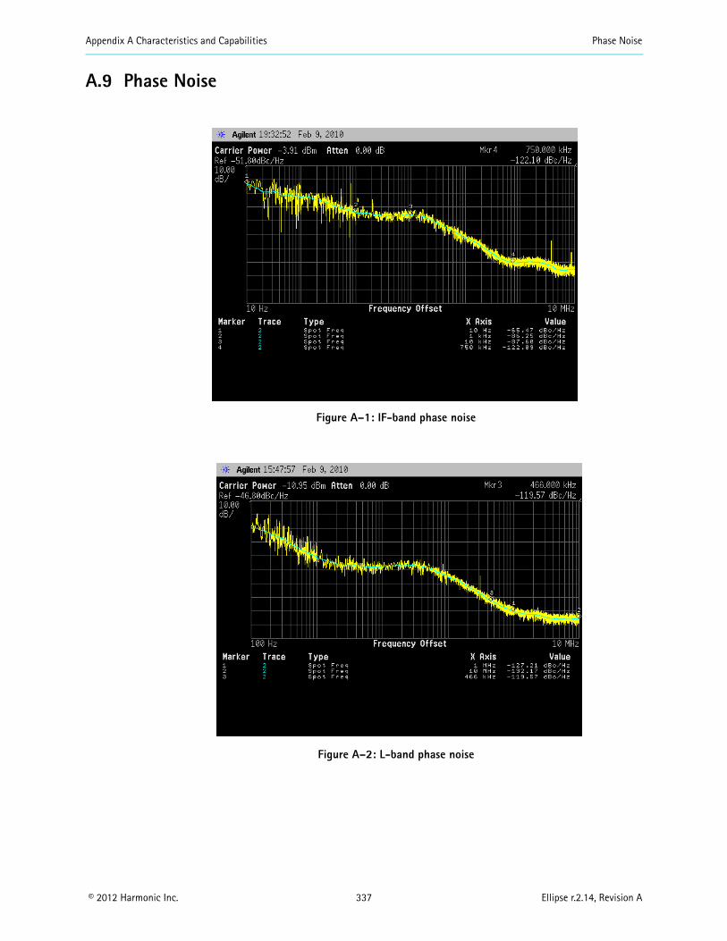
Appendix A Characteristics and Capabilities Phase Noise
© 2012 Harmonic Inc. 337 Ellipse r.2.14, Revision A
A.9 Phase Noise
Figure A–1: IF-band phase noise
Figure A–2: L-band phase noise
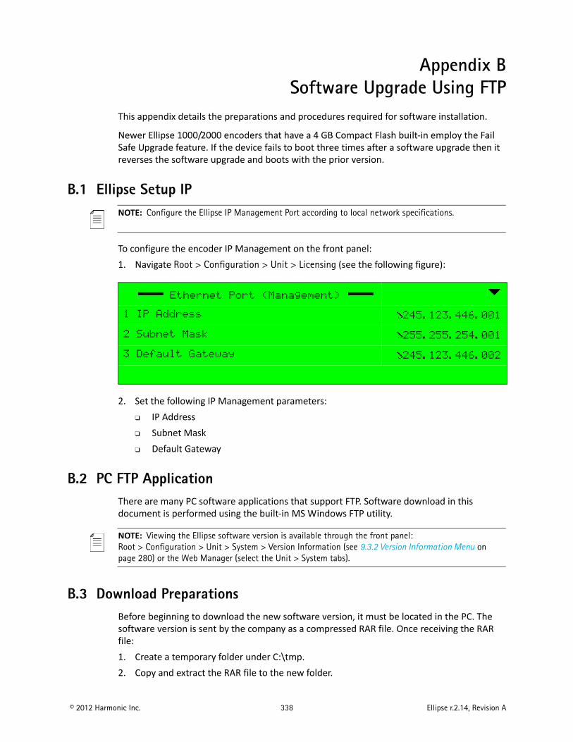
© 2012 Harmonic Inc. 338 Ellipse r.2.14, Revision A
Appendix BSoftware Upgrade Using FTP
This appendix details the preparations and procedures required for software installation.
Newer Ellipse 1000/2000 encoders that have a 4 GB Compact Flash built-in employ the Fail Safe Upgrade feature. If the device fails to boot three times after a software upgrade then it reverses the software upgrade and boots with the prior version.
B.1 Ellipse Setup IPNOTE: Configure the Ellipse IP Management Port according to local network specifications.
To configure the encoder IP Management on the front panel:1. Navigate Root > Configuration > Unit > Licensing (see the following figure):
2. Set the following IP Management parameters: IP Address Subnet Mask Default Gateway
B.2 PC FTP ApplicationThere are many PC software applications that support FTP. Software download in this document is performed using the built-in MS Windows FTP utility.
NOTE: Viewing the Ellipse software version is available through the front panel: Root > Configuration > Unit > System > Version Information (see 9.3.2 Version Information Menu on page 280) or the Web Manager (select the Unit > System tabs).
B.3 Download PreparationsBefore beginning to download the new software version, it must be located in the PC. The software version is sent by the company as a compressed RAR file. Once receiving the RAR file:1. Create a temporary folder under C:\tmp.2. Copy and extract the RAR file to the new folder.
Ethernet Port (Management)
1 IP Address 245.123.446.001
2 Subnet Mask 255.255.254.001
3 Default Gateway 245.123.446.002
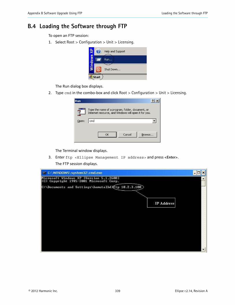
Appendix B Software Upgrade Using FTP Loading the Software through FTP
© 2012 Harmonic Inc. 339 Ellipse r.2.14, Revision A
B.4 Loading the Software through FTPTo open an FTP session:1. Select Root > Configuration > Unit > Licensing.
The Run dialog box displays.2. Type cmd in the combo-box and click Root > Configuration > Unit > Licensing.
The Terminal window displays.3. Enter ftp <Ellipse Management IP address> and press <Enter>.
The FTP session displays.
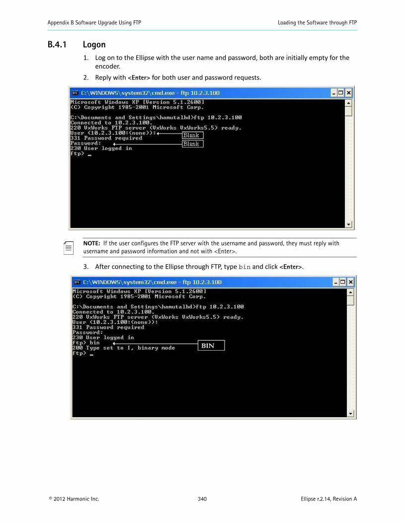
Appendix B Software Upgrade Using FTP Loading the Software through FTP
© 2012 Harmonic Inc. 340 Ellipse r.2.14, Revision A
B.4.1 Logon1. Log on to the Ellipse with the user name and password, both are initially empty for the
encoder.2. Reply with <Enter> for both user and password requests.
NOTE: If the user configures the FTP server with the username and password, they must reply with username and password information and not with <Enter>.
3. After connecting to the Ellipse through FTP, type bin and click <Enter>.
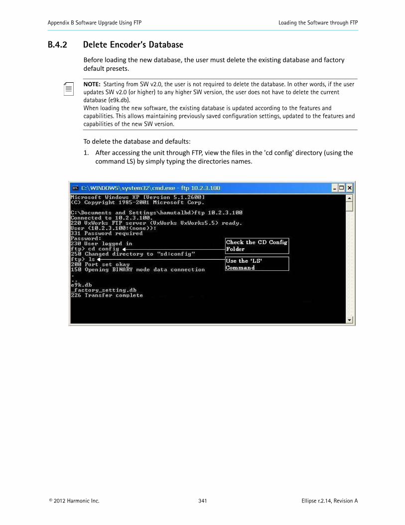
Appendix B Software Upgrade Using FTP Loading the Software through FTP
© 2012 Harmonic Inc. 341 Ellipse r.2.14, Revision A
B.4.2 Delete Encoder’s Database
Before loading the new database, the user must delete the existing database and factory default presets.
NOTE: Starting from SW v2.0, the user is not required to delete the database. In other words, if the user updates SW v2.0 (or higher) to any higher SW version, the user does not have to delete the current database (e9k.db).When loading the new software, the existing database is updated according to the features and capabilities. This allows maintaining previously saved configuration settings, updated to the features and capabilities of the new SW version.
To delete the database and defaults:1. After accessing the unit through FTP, view the files in the 'cd config' directory (using the
command LS) by simply typing the directories names.

Appendix B Software Upgrade Using FTP Loading the Software through FTP
© 2012 Harmonic Inc. 342 Ellipse r.2.14, Revision A
2. Locate the e9k.db and _factory_setting.db database files. In the previous example, these files are located under config directory.
3. Delete the e9k.db and _factory_setting.db files. To do so, type the command 'rm' with the filename (for example, 'rm e9k.db').
4. Verify the removal of the files by returning to the files’ previous location once again (in this example, the config folder) and verify that the files are removed.
5. Enter cd .. to return to the root directory of the encoder.6. Proceed to B.4.3 Loading the File.
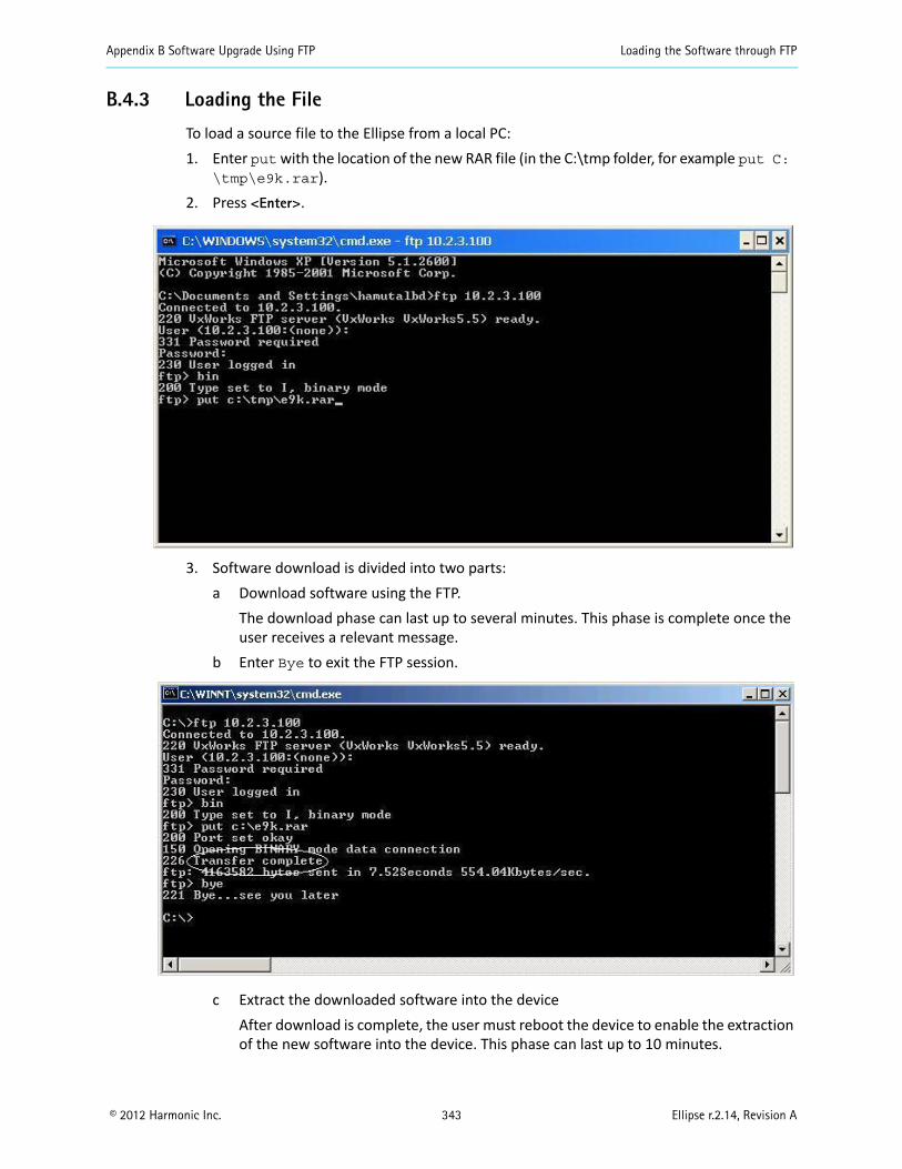
Appendix B Software Upgrade Using FTP Loading the Software through FTP
© 2012 Harmonic Inc. 343 Ellipse r.2.14, Revision A
B.4.3 Loading the File
To load a source file to the Ellipse from a local PC:1. Enter put with the location of the new RAR file (in the C:\tmp folder, for example put C:
\tmp\e9k.rar).2. Press <Enter>.
3. Software download is divided into two parts:a Download software using the FTP.
The download phase can last up to several minutes. This phase is complete once the user receives a relevant message.
b Enter Bye to exit the FTP session.
c Extract the downloaded software into the deviceAfter download is complete, the user must reboot the device to enable the extraction of the new software into the device. This phase can last up to 10 minutes.

Appendix B Software Upgrade Using FTP Loading the Software through FTP
© 2012 Harmonic Inc. 344 Ellipse r.2.14, Revision A
Once the extraction is complete, the device reboots itself.After a second boot, download is complete.
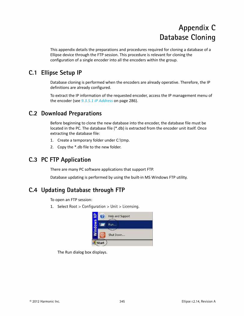
© 2012 Harmonic Inc. 345 Ellipse r.2.14, Revision A
Appendix CDatabase Cloning
This appendix details the preparations and procedures required for cloning a database of a Ellipse device through the FTP session. This procedure is relevant for cloning the configuration of a single encoder into all the encoders within the group.
C.1 Ellipse Setup IPDatabase cloning is performed when the encoders are already operative. Therefore, the IP definitions are already configured.
To extract the IP information of the requested encoder, access the IP management menu of the encoder (see 9.3.5.1 IP Address on page 286).
C.2 Download PreparationsBefore beginning to clone the new database into the encoder, the database file must be located in the PC. The database file (*.db) is extracted from the encoder unit itself. Once extracting the database file:1. Create a temporary folder under C:\tmp.2. Copy the *.db file to the new folder.
C.3 PC FTP ApplicationThere are many PC software applications that support FTP.
Database updating is performed by using the built-in MS Windows FTP utility.
C.4 Updating Database through FTPTo open an FTP session:1. Select Root > Configuration > Unit > Licensing.
The Run dialog box displays.
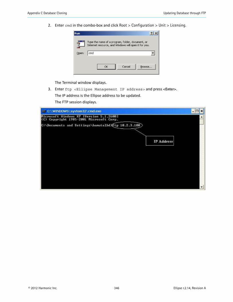
Appendix C Database Cloning Updating Database through FTP
© 2012 Harmonic Inc. 346 Ellipse r.2.14, Revision A
2. Enter cmd in the combo-box and click Root > Configuration > Unit > Licensing.
The Terminal window displays.3. Enter ftp <Ellipse Management IP address> and press <Enter>.
The IP address is the Ellipse address to be updated.The FTP session displays.
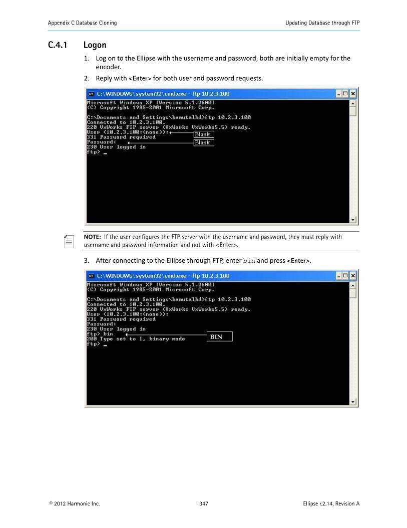
Appendix C Database Cloning Updating Database through FTP
© 2012 Harmonic Inc. 347 Ellipse r.2.14, Revision A
C.4.1 Logon1. Log on to the Ellipse with the username and password, both are initially empty for the
encoder.2. Reply with <Enter> for both user and password requests.
NOTE: If the user configures the FTP server with the username and password, they must reply with username and password information and not with <Enter>.
3. After connecting to the Ellipse through FTP, enter bin and press <Enter>.
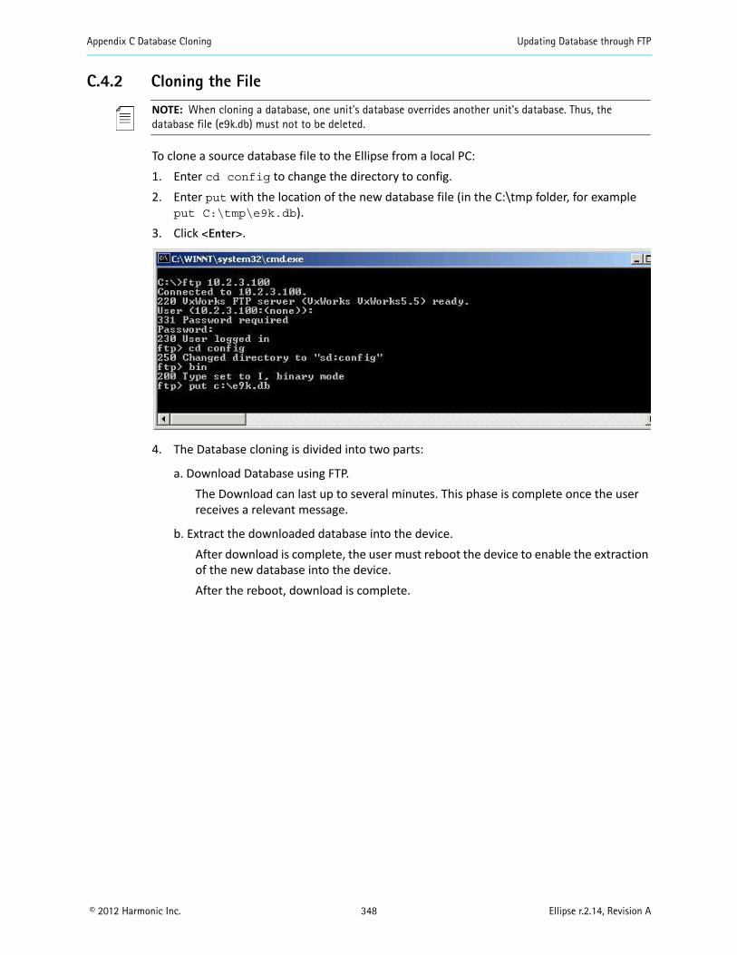
Appendix C Database Cloning Updating Database through FTP
© 2012 Harmonic Inc. 348 Ellipse r.2.14, Revision A
C.4.2 Cloning the File
NOTE: When cloning a database, one unit's database overrides another unit's database. Thus, the database file (e9k.db) must not to be deleted.
To clone a source database file to the Ellipse from a local PC:1. Enter cd config to change the directory to config.2. Enter put with the location of the new database file (in the C:\tmp folder, for example
put C:\tmp\e9k.db).3. Click <Enter>.
4. The Database cloning is divided into two parts:
a. Download Database using FTP.The Download can last up to several minutes. This phase is complete once the user receives a relevant message.
b. Extract the downloaded database into the device.After download is complete, the user must reboot the device to enable the extraction of the new database into the device. After the reboot, download is complete.
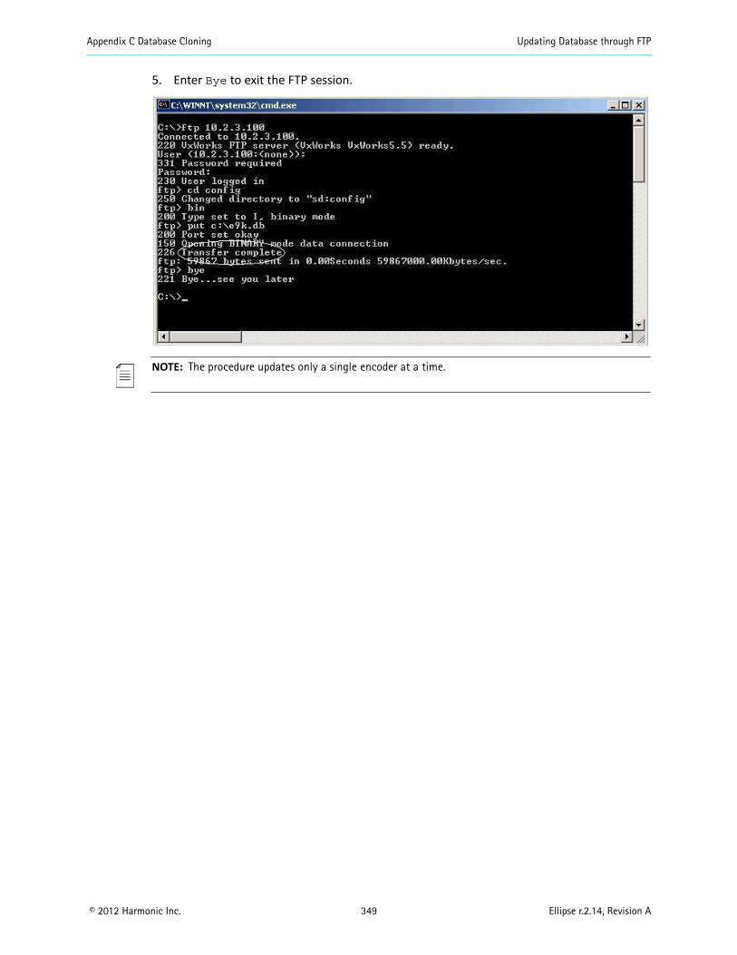
Appendix C Database Cloning Updating Database through FTP
© 2012 Harmonic Inc. 349 Ellipse r.2.14, Revision A
5. Enter Bye to exit the FTP session.
NOTE: The procedure updates only a single encoder at a time.
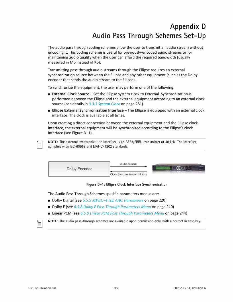
© 2012 Harmonic Inc. 350 Ellipse r.2.14, Revision A
Appendix DAudio Pass Through Schemes Set-Up
The audio pass through coding schemes allow the user to transmit an audio stream without encoding it. This coding scheme is useful for previously-encoded audio streams or for maintaining audio quality when the user can afford the required bandwidth (usually measured in Mb instead of Kb).
Transmitting pass through audio streams through the Ellipse requires an external synchronization source between the Ellipse and any other equipment (such as the Dolby encoder that sends the audio stream to the Ellipse).
To synchronize the equipment, the user may perform one of the following: External Clock Source – Set the Ellipse system clock to External. Synchronization is
performed between the Ellipse and the external equipment according to an external clock source (see details in 9.3.3 System Clock on page 281).
Ellipse External Synchronization Interface – The Ellipse is equipped with an external clock interface. The clock is available at all times.
Upon creating a direct connection between the external equipment and the Ellipse clock interface, the external equipment will be synchronized according to the Ellipse’s clock interface (see Figure D–1).
NOTE: The external synchronization interface is an AES3/EBBU transmitter at 48 kHz. The interface complies with IEC-60958 and EIAI-CP1202 standards.
Figure D–1: Ellipse Clock Interface Synchronization
The Audio Pass Through Schemes specific-parameters menus are: Dolby Digital (see 6.5.5 MPEG-4 HE AAC Parameters on page 220) Dolby E (see 6.5.8 Dolby E Pass Through Parameters Menu on page 240) Linear PCM (see 6.5.9 Linear PCM Pass Through Parameters Menu on page 244)
NOTE: The audio pass-through schemes are available upon permission only, with a correct license key.

© 2012 Harmonic Inc. 351 Ellipse r.2.14, Revision A
Appendix EDS9034PCX PowerCap
1 of 3 REV: 052107
GENERAL DESCRIPTION The DS9034PCX PowerCap is designed to be a lithium power source for nonvolatile timekeeping RAMs in Dallas Semiconductor’s directly surface-mountable PowerCap Module (PCM) package. After a PowerCap module board has been soldered in place and cleaned, the DS9034PCX PowerCap is placed on top of the PCM board to form a complete PowerCap module package. The PowerCap is keyed to prevent incorrect attachment.
The DS9034PCX can be easily removed by inserting a regular screwdriver into a detachment feature and prying gently outward and upward to release the PowerCap from the PowerCap module board.
ABSOLUTE MAXIMUM RATINGS Storage Temperature Range: -40°C to +85°C
Stresses beyond those listed under “Absolute Maximum Ratings” may cause permanent damage to the device. These are stress ratings only, and functional operation of the device at these or any other conditions beyond those indicated in the operational sections of the specifications is not implied. Exposure to the absolute maximum rating conditions for extended periods may affect device.
BATTERY CHARACTERISTICS Nominal Voltage: 3V Nominal Capacity: 130mAhr Chemistry: Li(CF)x
CRYSTAL CHARACTERISTICS Nominal Frequency: 32.768kHz Load Capacitance: 6pF
FEATURESProvides 10 Years of Battery Backup Power for Nonvolatile Timekeeping RAMs in the PowerCap Module Package (PCM)
Snaps Directly Onto Surface-Mounted PowerCap Module Boards
Detachment Feature Allows Easy Removal
Compatible with these 34-Pin PowerCap Module Boards: DS1386P DS1543P/YP/WP DS1486P DS1553P/YP/WP DS1643P DS1554P/YP/WP DS1644P DS1556P/YP/WP DS1646P DS1557P/YP/WP DS1647P DS1744P/YP/WP DS1743P/WP DS1746P/YP/WP DS1251YP/WP DS1747P/YP/WP DS1248YP/WP DS1244YP/WP
PACKAGE INFORMATION
PIN DESCRIPTION NAME FUNCTION X1, X2 32.768kHz Crystal ConnectionsVBAT +3V Battery OutputGND Ground
DS9034PCXPowerCap with Crystal
www.maxim-ic.com
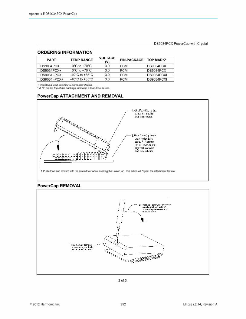
Appendix E DS9034PCX PowerCap
© 2012 Harmonic Inc. 352 Ellipse r.2.14, Revision A
DS9034PCX PowerCap with Crystal
2 of 3
ORDERING INFORMATION PART TEMP RANGE VOLTAGE
(V) PIN-PACKAGE TOP MARK*
DS9034PCX 0°C to +70°C 3.0 PCM DS9034PCX DS9034PCX+ 0°C to +70°C 3.0 PCM DS9034PCX DS9034I-PCX -40°C to +85°C 3.0 PCM DS9034PCXI DS9034I-PCX+ -40°C to +85°C 3.0 PCM DS9034PCXI
+ Denotes a lead-free/RoHS-compliant device.* A “+” on the top of the package indicates a lead-free device.
PowerCap ATTACHMENT AND REMOVAL
PowerCap REMOVAL
3. Push down and forward with the screwdriver while inserting the PowerCap. This action will “open” the attachment feature.
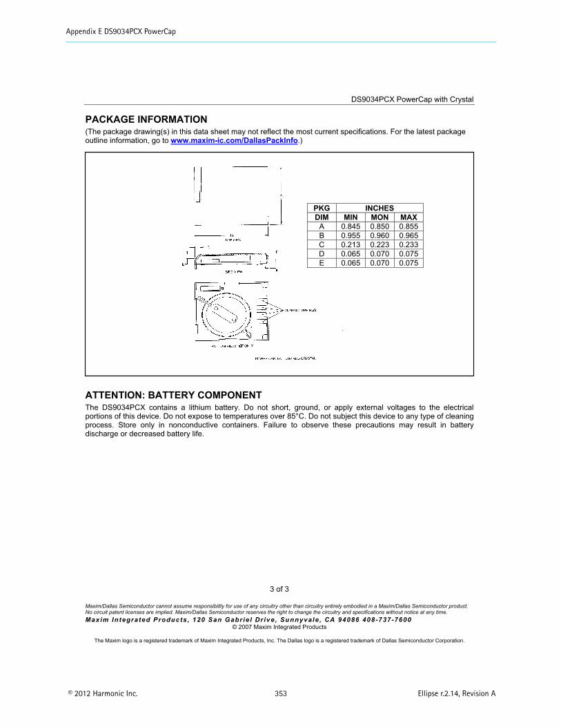
Appendix E DS9034PCX PowerCap
© 2012 Harmonic Inc. 353 Ellipse r.2.14, Revision A
DS9034PCX PowerCap with Crystal
3 of 3
Maxim/Dallas Semiconductor cannot assume responsibility for use of any circuitry other than circuitry entirely embodied in a Maxim/Dallas Semiconductor product. No circuit patent licenses are implied. Maxim/Dallas Semiconductor reserves the right to change the circuitry and specifications without notice at any time. Maxim Integrated Products , 120 San Gabrie l Dr ive , Sunnyvale , CA 94086 408-737-7600
© 2007 Maxim Integrated Products
The Maxim logo is a registered trademark of Maxim Integrated Products, Inc. The Dallas logo is a registered trademark of Dallas Semiconductor Corporation.
PACKAGE INFORMATION (The package drawing(s) in this data sheet may not reflect the most current specifications. For the latest package outline information, go to www.maxim-ic.com/DallasPackInfo.)
ATTENTION: BATTERY COMPONENT The DS9034PCX contains a lithium battery. Do not short, ground, or apply external voltages to the electrical portions of this device. Do not expose to temperatures over 85°C. Do not subject this device to any type of cleaning process. Store only in nonconductive containers. Failure to observe these precautions may result in battery discharge or decreased battery life.
PKG INCHES DIM MIN MON MAX
A 0.845 0.850 0.855 B 0.955 0.960 0.965 C 0.213 0.223 0.233 D 0.065 0.070 0.075 E 0.065 0.070 0.075
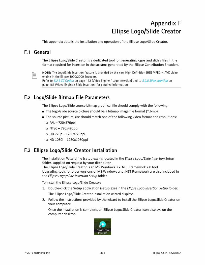
© 2012 Harmonic Inc. 354 Ellipse r.2.14, Revision A
Appendix FEllipse Logo/Slide Creator
This appendix details the installation and operation of the Ellipse Logo/Slide Creator.
F.1 GeneralThe Ellipse Logo/Slide Creator is a dedicated tool for generating logos and slides files in the format required for insertion in the streams generated by the Ellipse Contribution Encoders.
NOTE: The Logo/Slide insertion feature is provided by the new High Definition (HD) MPEG-4 AVC video engine in the Ellipse 1000/2000 Encoders.Refer to 5.2.6 CC Option on page 162 (Video Engine / Logo Insertion) and to 5.2.8 Slide Insertion on page 168 (Video Engine / Slide Insertion) for detailed information.
F.2 Logo/Slide Bitmap File ParametersThe Ellipse Logo/Slide source bitmap graphical file should comply with the following: The logo/slide source picture should be a bitmap image file format (*.bmp). The source picture size should match one of the following video format and resolutions:
PAL – 720x576ppi NTSC – 720x480ppi HD 720p – 1280x720ppi HD 1080i – 1280x1080ppi
F.3 Ellipse Logo/Slide Creator InstallationThe Installation Wizard file (setup.exe) is located in the Ellipse Logo/Slide Insertion Setup folder, supplied on request by your distributor. The Ellipse Logo/Slide Creator is an MS Windows 3.x .NET Framework 2.0 tool. Upgrading tools for older versions of MS Windows and .NET Framework are also included in the Ellipse Logo/Slide Insertion Setup folder.
To install the Ellipse Logo/Slide Creator:1. Double-click the Setup application (setup.exe) in the Ellipse Logo Insertion Setup folder.
The Ellipse Logo/Slide Creator Installation wizard displays.2. Follow the instructions provided by the wizard to install the Ellipse Logo/Slide Creator on
your computer.Once the installation is complete, an Ellipse Logo/Slide Creator Icon displays on the computer desktop.
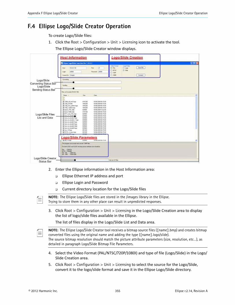
Appendix F Ellipse Logo/Slide Creator Ellipse Logo/Slide Creator Operation
© 2012 Harmonic Inc. 355 Ellipse r.2.14, Revision A
F.4 Ellipse Logo/Slide Creator OperationTo create Logo/Slide files:1. Click the Root > Configuration > Unit > Licensing icon to activate the tool.
The Ellipse Logo/Slide Creator window displays.
2. Enter the Ellipse information in the Host Information area: Ellipse Ethernet IP address and port Ellipse Login and Password Current directory location for the Logo/Slide files
NOTE: The Ellipse Logo/Slide files are stored in the /images library in the Ellipse.Trying to store them in any other place can result in unpredicted responses.
3. Click Root > Configuration > Unit > Licensing in the Logo/Slide Creation area to display the list of logo/slide files available in the Ellipse.The list of files display in the Logo/Slide List and Data area.
NOTE: The Ellipse Logo/Slide Creator tool receives a bitmap source files (name.bmp) and creates bitmap converted files using the original name and adding the type (name.logo/slide).The source bitmap resolution should match the picture attribute parameters (size, resolution, etc…), as detailed in paragraph Logo/Slide Bitmap File Parameters.
4. Select the Video Format (PAL/NTSC/720P/1080I) and type of file (Logo/Slide) in the Logo/Slide Creation area.
5. Click Root > Configuration > Unit > Licensing to select the source for the Logo/Slide, convert it to the logo/slide format and save it in the Ellipse Logo/Slide directory.
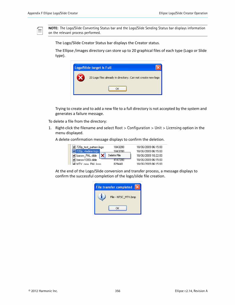
Appendix F Ellipse Logo/Slide Creator Ellipse Logo/Slide Creator Operation
© 2012 Harmonic Inc. 356 Ellipse r.2.14, Revision A
NOTE: The Logo/Slide Converting Status bar and the Logo/Slide Sending Status bar displays information on the relevant process performed.
The Logo/Slide Creator Status bar displays the Creator status.
The Ellipse /images directory can store up to 20 graphical files of each type (Logo or Slide type).
Trying to create and to add a new file to a full directory is not accepted by the system and generates a failure message.
To delete a file from the directory:1. Right-click the filename and select Root > Configuration > Unit > Licensing option in the
menu displayed.A delete confirmation message displays to confirm the deletion.
At the end of the Logo/Slide conversion and transfer process, a message displays to confirm the successful completion of the logo/slide file creation.
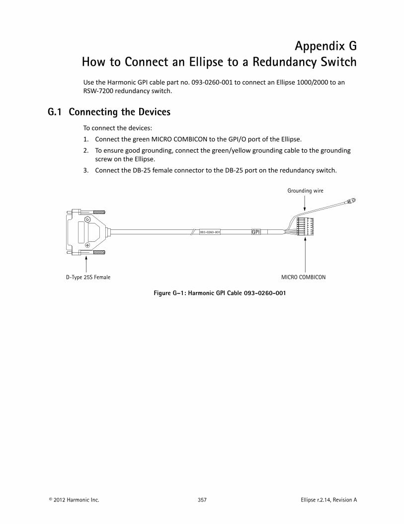
© 2012 Harmonic Inc. 357 Ellipse r.2.14, Revision A
Appendix GHow to Connect an Ellipse to a Redundancy SwitchUse the Harmonic GPI cable part no. 093-0260-001 to connect an Ellipse 1000/2000 to an RSW-7200 redundancy switch.
G.1 Connecting the DevicesTo connect the devices:1. Connect the green MICRO COMBICON to the GPI/O port of the Ellipse.2. To ensure good grounding, connect the green/yellow grounding cable to the grounding
screw on the Ellipse.3. Connect the DB-25 female connector to the DB-25 port on the redundancy switch.
Figure G–1: Harmonic GPI Cable 093-0260-001
MICRO COMBICOND-Type 25S Female
Grounding wire
GPI093-0260-001

Glossary
Numerics A B C D E F G H I J L M N O P Q R S T U V W Y
© 2012 Harmonic Inc. 358 Ellipse r.2.14, Revision A
Glossary
Numerics 10BASE-T
An IEEE standard, sometimes called “Ethernet,” that uses a twisted pair cable, with RJ-45 connectors, often connected in a star configuration through a hub. The maximum allowable cable length is 328 feet. A 10BASE-T system operates at 10 Mbps. See also 100BASE-T.
100BASE-T
An IEEE standard, sometimes called “Ethernet,” that supports data rates up to 100 Mbps, also known as Fast Ethernet. 100BASE-T uses twisted pair cable. See also 10BASE-T.
3:2 pulldown
A method that converts 24 frames per second motion picture film frame rate material to 30 frames per second interlaced video frame rate. This process is normally done by a telecine. It refers to using two film frames to generate five video fields of interlaced video (1080i or 480i). The first frame is scanned three times to generate three video fields, the second frame is scanned twice to generate two video fields, and the cadence continues. Note that every fifth frame will have images from different film frames. These are termed “dirty frames” as there may be significant differences in the two fields of video. The 3:2 process can also be applied for 720P progressive video, this results in a 2:3 cadence of video frames, without the “dirty frame” artifacts.
4:2:0
A component digital system that subsamples chroma components both vertically and horizontally by a factor of two with respect to luma.
4:2:2
A component digital system that represents a luma component and a chroma component subsampled horizontally by a factor of two with respect to luma.
A AAA
Audio adapter used in the MV family of encoders. Can compress two stereo pairs of either analog or digital audio into either MPEG-1 layer II or Dolby Digital1 (AC-3) formats.
AAC LC
Advanced Audio Codec Low Complexity.
1. Dolby, Dolby Digital, Dolby Digital Plus, and Dolby E are registered trademarks of Dolby Laboratories.
Glossary
Numerics A B C D E F G H I J L M N O P Q R S T U V W Y
© 2012 Harmonic Inc. 359 Ellipse r.2.14, Revision A
AAL5
ATM Adaptation Layer 5. Performs the functions necessary to adapt frame oriented data information, such as MPEG transport streams and IP datagrams, to the ATM cell format.
AC-3
Also known as Dolby Digital.
ACG
Access Control Group. An identifier that links control words (CWs), entitlement control messages (ECMs), and packet identifiers (PIDs) to a common group.
ACM
A card for the MN20 multiplexer. The ACM supports DES and DVB protocols.
adapter
A circuit board in a Harmonic encoder. Adapters have input or output ports. Also known as a card or a blade.
AEM
Audio adapter used in MN20 remultiplexer, it can compress two stereo pairs of either analog or digital audio into the MPEG-1 layer II.
AES3 Standard
The standard for serial transport of digital audio in professional devices, developed by the Audio Engineering Society (AES) originally in 1992. It has been revised a number of times since then, with the current revision published in 2010, breaking the original document into multiple Parts. Some obsolete references term it “AES/EBU,” since the EBU also published the original document in 1992 as EBU Tech. 3250.
AFD
Active Format Description. Signaling describes certain spatial characteristics of a high definition or standard definition video image. AFD and Bar Data are intended to be broadcast with the video signal that they describe. AFD information is intended to assist DTV displays in optimizing the displayed images. AFD may also be used by intermediate professional video equipment in conversion of video images of one aspect ratio into an image of another aspect ratio. Bar Data information is used to signal the precise unused areas of active video when the active image does not completely fill the picture area, in particular widescreen cinema material carried letterboxed in a frame with bars top and bottom. AFD is documented by SMPTE 2016 (multiple part document) and its carriage in compressed video is documented in DVB/ETSI TS 101 154, ATSC A/53 Part 4, ATSC A/72 Part 1, SCTE 128, and other standards.
AGC
Automatic Gain Control. Keeps the output signal of a circuit constant while the input signal amplitude varies.
Glossary
Numerics A B C D E F G H I J L M N O P Q R S T U V W Y
© 2012 Harmonic Inc. 360 Ellipse r.2.14, Revision A
AHC
Audio adapter used in the Electra/Ion family of encoders. Can compress up to three stereo pairs of digital audio into either MPEG-1 layer II, MPEG-2/MPEG-4 AAC/HE AAC, or Dolby Digital (AC-3) formats. The AHC has 3 variants: AHC-RAC, AHC-561, and the “On-board” adapter, which is simply an AHC-RAC without external connectors (which means it can only encode embedded audio).
AHC-561
Audio adapter used in the Electra/Ion family of encoders which hosts a Dolby Cat. 561 compression module. The Cat. 561 can transcode Dolby E to either Dolby Digital (AC-3) or Dolby Digital Plus (E-AC-3, see AHC) or Dolby Digital to Dolby Digital Plus.
AHC-RAC
Audio adapter used in the Electra/Ion family of encoders. Can compress a multi-channel audio sound field (from either AES3 or embedded digital inputs, see AHC) into either Dolby Digital (AC-3), Dolby Digital Plus (E-AC-3), or MPEG-2/MPEG-4 AAC or HE AAC. Alternatively it can compress three unrelated stereo pairs of digital audio into either MPEG-1 layer II, MPEG-2/MPEG-4 AAC/HE AAC/HE AAC v2, or Dolby Digital (AC-3).
AIC
Audio adapter used in the Electra/Ion family of encoders. Can compress two stereo pairs of either analog or digital audio into either MPEG-1 layer II, MPEG-2/MPEG-4 AAC/HE AAC, or Dolby Digital (AC-3) formats.
AIM
A card for the MN20 multiplexer. Provides a DVB-ASI interface for the MN20 remultiplexer. It accepts up to four MPEG-2 Transport Streams in the DVB-ASI electrical interface format (270 mbps).
Alarm Indicator
Displayed in the title bar of each web client page of the device. It appears in red when an alarm is issued and notifies of a fault and of its nature.
AMOL
Automated Measurement of Lineups.
Any to Any Routing
Allows you to define a network group for connecting services from different input and output devices in associated encoding and multiplexing network groups.
AOM
A card for the MN20 multiplexer. The AOM transmits MPEG-2 transport stream packets over a 155 MB/sec interface (either STS-3c/OC-3 or STM-1). The transport stream packets are first encapsulated into ATM Adaptation Layer 5 (AAL-5) PDUs then segmented into ATM cells. The cells undergo ATM constant bit rate traffic shaping before egress to assure that the appropriate quality of service is maintained. The AOM is an output option for the MN20 remultiplexer.
Glossary
Numerics A B C D E F G H I J L M N O P Q R S T U V W Y
© 2012 Harmonic Inc. 361 Ellipse r.2.14, Revision A
API
Application Programming Interface. A term applied to software libraries, functions, and tools for building software applications.
ARAP
Advanced Resource Allocation Protocol.
ARM and ARM-4
A card for the MN20 multiplexer. Provides a DVB-ASI interface for the MN20 remultiplexer. It accepts up to four independent MPTSs in either the DVB-ASI or M2S protocol. Harmonic redesigned the ARM module resulting in the ARM-4 module, which has the same functionality as the ARM module.
ARP
Address Resolution Protocol. Used for communications between network devices. See BOOTP.
ASI
Asynchronous Serial Interface. A DVB-defined electrical interface for carrying MPEG-2 transport streams at a defined transmission rate within a 270 Mbps carrier.
ATM
Asynchronous Transfer Mode. A high-bandwidth, low-delay switching and multiplexing technology for delivering high-speed data, including digital video and audio.
ATSC
Advanced Television Systems Committee. Establishes standards for digital terrestrial television system in the US and other countries.
Bbalanced audio
Audio that is transmitted differentially, that is, sending the positive and negative signals of an audio waveform so that the audio arrives undistorted because noise is cancelled out. See also unbalanced audio.
bandwidth
The maximum amount of data that a transmission device (cable, fiber-optics link, satellite feed, and so on) is capable of carrying.
bandwidth allocation
The process of assigning portions of the total bandwidth on the basis of the requirements of the program material. A channel that requires a high-quality picture, for example, a live sports broadcast, might be allocated a high bandwidth. A channel that can be transmitted with a lower-quality picture, for example, a VCR-quality movie, might be assigned a lower bandwidth.
Glossary
Numerics A B C D E F G H I J L M N O P Q R S T U V W Y
© 2012 Harmonic Inc. 362 Ellipse r.2.14, Revision A
Base quant
A measure of the “loss” introduced by the coding process. This is an indication of the degradation in video quality produced by the encoder.
Base quant is the average of the quantization scales used for encoding video during the sampling period. The range is 0 to 130. A low value means less video quality degradation.
BER
Bit Error Rate. The ratio of bits transmitted in error to the total bits sent. For example, a BER of 106 means 1 bit in a million is received in error.
BISS
Basic Interoperable Scrambling System. An open standard for protecting digital contribution applications.
Bit rate
The average bitrate of the bit stream, in bits per second, during the sampling period.
Black video
A video signal where there is no luminance or chrominance information. Either intentionally created for a short period of time or the result of a failure in a transmission system.
blanking interval
The process or time period when the cathode ray tube (CRT) beam is turned off so that the beam retrace does not interfere with the picture.
BNC
A standard coaxial cable connector named for the inventors (Neill and Concelman) and the connection type (bayonet).
BOOTP
Bootstrap Protocol. Used to supply hosts with IP addresses and a TFTP boot file name. BOOTP requests and replies are encapsulated in a User Datagram Protocol (UDP) packet. The BOOTP server uses an address resolution protocol (ARP) cache to map MAC addresses to IP addresses. When the server receives a BOOTP request from a MAC address listed in its cache, the server sends a reply to the MAC address.
broadcast encoding system
An assembly of components that compresses, multiplexes, and scrambles program material.
broadcast modulator
See modulator.
C CA
Conditional Access. Provides operator control over customer access to broadcast materials.
Glossary
Numerics A B C D E F G H I J L M N O P Q R S T U V W Y
© 2012 Harmonic Inc. 363 Ellipse r.2.14, Revision A
CA Descriptor
A descriptor which may be added to the PMT and identifies the CA system and other information related to that system.
CAM
Acronym for CA Module and is a standardized card which is used to unscramble services.
card
See adapter.
carrier frequency range
For a receiver, the range of valid input signals.
CAS
Conditional Access System. Scrambles the programming material and allows conditional access to the descrambled information on the basis of subscriber authorization. In consumer applications, CAS allows access to certain programs on the basis of a monetary exchange. In commercial applications, CAS allows controlled access to proprietary programs.
CAT
Conditional Access Table. The CAT informs the receiver of conditional access system (CAS) information, such as the EMMstream for provisioning the receiver.
CBR
Constant Bit Rate.
CC
Closed Captions or Continuity Counter. Readers are cautioned to avoid use of this abbreviation unless it is clearly stated in context.
CEA
Consumer Electronics Association.
CEA-608
Line 21 Data Services.
CEA-708
Digital Television (DTV) Closed Captioning.
channel
For NMX, a collection of circuits (video, audio, data, EMM, and ECM Generator) that are related to each other in the Program Association Table. See also PAT.
chroma
The color difference component of the video signal. Sometimes termed “chrominance.” See also luma.
Glossary
Numerics A B C D E F G H I J L M N O P Q R S T U V W Y
© 2012 Harmonic Inc. 364 Ellipse r.2.14, Revision A
CIFS
Common Internet File System.
circuit
For NMX Digital Service Manager, an elementary stream that carries audio, video, or data. Each circuit is assigned a unique PID.
closed captioning
The process of encoding, transmitting, decoding, and displaying program-related text typically on the lower part of a monitor or television during broadcast. See CEA-608 and CEA-708 standards.
CMTS
Cable Modem Termination System. Defined by CableLabs DOCSIS Base Specifications.
CO
Central Office.
color burst
The portion of the analog composite video waveform that sits between the horizontal sync and the start of active video. The color burst tells the monitor how to decode the color information contained in that line of active video.
companion key
Refers to a use of the keypad that is found on some Harmonic products. When using key combinations such as Shift + v, each of the two keys is a companion to the other.
component
A portion of a signal or system.
concealment motion vectors
Provide a functionality similar to the dropout compensator in a video tape recorder. Concealed vectors aid in error recovery but consume some of the available bandwidth and might not be supported by some decoders.
conditional access
See CAS.
Configuring
Defining the parameters of platform, input and output ports.
convolutional code
See FEC.
Copper Cable
A slang term for an electrical (as opposed to optical) cable interface. Copper cables are typically coaxial or twisted wire, but other physical variants may be found.

Glossary
Numerics A B C D E F G H I J L M N O P Q R S T U V W Y
© 2012 Harmonic Inc. 365 Ellipse r.2.14, Revision A
CORBA
Common Object Request Broker Architecture.
CP
Crypto Period. A parameter specifying the period during which data is scrambled with a particular Control Word (“key”).
CPE
Customer Premises Equipment.
crosstalk
The interference of a signal from an adjacent signal.
CRT
Cathode Ray Tube.
Cue Tone
A sequence of audio tones (typically DTMF tones) used to prompt an action.
CW
Control Word. A value that the CASgenerates to scramble the program data stream.
CWG
Control Word Generator. Generates the encryption key.
D data link
The continuous flow of information from one location to another
data stream
The continuous flow of information from one location to another.
datacast
A system that inserts data into an MPEG-2 Transport Stream and enables high bit-rate data download and recovery at the receiver. The data can be related to the video/audio elementary streams.
datagram packing
Datagram packing places datagram sections back-to-back within the payloads of TS packets. Adaptation field stuffing and section stuffing are not performed, and datagrams are not aligned to the beginning of the TS packetpayload.

Glossary
Numerics A B C D E F G H I J L M N O P Q R S T U V W Y
© 2012 Harmonic Inc. 366 Ellipse r.2.14, Revision A
datagram section
An MPEG-2 section that consists of a datagram header, payload, and a checksum or cyclic redundancy check (CRC). The maximum size of a section is 4096 bytes with a variable size header, depending on the type of data.
DB-9
A 9-pin connector used to connect communications and other electronic devices. It is commonly used for TIA-232 and similar interfaces.
dBm
Power ratio in decibels (dB) of the measured power referenced to one milliwatt.
DBS
Direct Broadcast Satellite. Describes a video entertainment broadcasting system over satellite to receivers at the customer (end user) home.
DCII
DigiCipher 2
DCE
Data Communications Equipment. A device that communicates with a DTE over TIA-232. For example, a modem is a DCE that sends to and accepts data from a host computer (DTE). See also DTE.
DD
Dolby Digital. See AC-3.
decoder
A device that converts an compressed signal back to baseband video and audio.
demultiplex
The conversion of several intermixed signals to l separate signals.
DHCP
Dynamic Host Configuration Protocol.
DHEI
Digital Headend Expansion Interface. An proprietary (Motorola) interface protocol for carrying MPEG-2 transport streams between headend equipment.
DHOM
A card for the MN20 multiplexer. The DHOM accepts DVB-ASI protocol input from the MOM and translates it to DHEI output. The DHOM provides three DVB-ASI input ports and three DHEI output ports.
Glossary
Numerics A B C D E F G H I J L M N O P Q R S T U V W Y
© 2012 Harmonic Inc. 367 Ellipse r.2.14, Revision A
differential transmission
The sending of the positive and negative aspects of a data signal so that it arrives undistorted. See also balanced audio.
DIM
A card for the MN20 multiplexer. Accepts either formatted or unformatted data on an Ethernet connection and packetizes this data for transmission in an MPEG-2 Transport Stream.
DIN connector
A plug and socket used to connect a variety of devices. DIN plugs are about 1/2-inch in diameter, with pins inside in a circular pattern. See also mini-DIN connector.
DiviTrack™
Harmonic’s proprietary closed loop statistical multiplex system. It is deployed using a variety of implementations, which are typically designated by letters appended to DiviTrack, such as DiviTrackIP. The DiviTrack system gives Harmonic’s encoders and multiplexers advanced warning of upcoming material by using LookAhead™ technology, resulting in outstanding compression efficiency, higher quality video, and better bandwidth utilization.
DiviTrack complexity
The average video complexity of the input video source during the sampling period. The range is 1 to 100.
This is an indication of the relative difficulty of compressing a video source. The ratio of DiviTrack complexity values between two sources is intended to indicate the relative bit rate required to code the two sources with equal visual quality. The value is used to assign bit rates to specific segments of a video sequence to attain constant visual quality. Usually, high complexity requires more bits to compress the video to achieve good quality.
DiviTrackIP
Harmonic’s DiviTrack system deployed over IP interfaces
DiviTrackMX
Harmonic’s DiviTrack system deployed internally within a single multichannel encoder.
DiviTrackXE
Harmonic’s DiviTrack system deployed over ASI interfaces.
DLL
Dynamic Link Library. Typically in software applications, a specific function or set of functions stored as a separate file. The main application loads the file only when needed.
DLM
A card for the MN20 multiplexer.
DNS
Domain Name System.
Glossary
Numerics A B C D E F G H I J L M N O P Q R S T U V W Y
© 2012 Harmonic Inc. 368 Ellipse r.2.14, Revision A
DOM
A card for the MN20 multiplexer which. transmits MPEG-2 Transport Streampackets over an ATM interface with a DS3 physical interface.
downconverter
A device used to lower one or more high-frequency signals to an intermediate range. See also LNB.
downstream
The direction of the communications service data flow. Broadcast services flow downstream from the service provider to the subscriber.
DPI
Digital Program Insertion. Also referred to as Splicing, is the process in which the main feed is spliced to allow the insertion of another stream, usually an ad.
DRM
Digital Rights Management.
DS3
A North American telephony interface standard, which operates at 44.736 Mbps over 75-ohm coaxial cable. See also DOM.
DSLAM
Digital Subscriber Line Access Multiplexer.
DTE
Data Terminal Equipment. A device that communicates with a DCE device over TIA-232. For example, a DTE is a computer that sends to and accepts data from a modem (DCE).
DTS
Decoding Time Stamp. An MPEG-2 defined field that can be present in the PES packet header to indicate the time the access unit is decoded in the system target decoder.
DTV
Digital Television.
dual channel
A channel that consists of two audio signals that are not related to each other, for example, the English and Japanese translation of a program’s audio.
DVB
Digital Video Broadcasting project of the EBU. Specifies transmission and related standards for Europe (primarily) as well as other parts of the world.
Glossary
Numerics A B C D E F G H I J L M N O P Q R S T U V W Y
© 2012 Harmonic Inc. 369 Ellipse r.2.14, Revision A
DVB-ASI
DVB Asynchronous Serial Interface. A 270 Mbps serial interface to carry MPEG-2 Transport Stream.
DVB-CI
Digital Video Broadcasting – Common Interface
DVB-S
Digital Video Broadcasting - Satellite.
DVB-S2
Digital Video Broadcasting - Satellite - second generation.
E ECM
Entitlement Control Message. An ECM is a message generated by the conditional access system ( CAS). The ECM contains an encrypted version of the control word that only authorized subscribers can decrypt. See also EMM.
ECM Stream
The data flow between ECMG and a multiplexer involved in the generation of a specific ECM.
ECMG
ECM Generator. A CAS application that produces the ECM messages.
EDH
Error Detection and Handling
EIA
Electronic Industries Alliance. A U.S. trade organization that was once responsible for establishing hardware interface standards. The EIA broke apart into several more specialized standards development organizations (SDOs) including the CEA and TIA. This break-up resulted in the renaming of a number of key standards (such as CEA-708 and TIA-232) which has caused industry confusion. Harmonic is careful to use the current and correct names of relevant standards.
EIT
Event Information Table. This table provides information in chronological order for the events contained within each service.
elementary stream
The basic raw output of either video or audio compression, not intended for physical manifestation beyond the creating device. Each elementary stream will be carried in a sequence of PESpackets with a single PID within the eventual TS.

Glossary
Numerics A B C D E F G H I J L M N O P Q R S T U V W Y
© 2012 Harmonic Inc. 370 Ellipse r.2.14, Revision A
embedded controller
A processing unit located within each componentthat is responsible for the control of that component.
EMM
Entitlement Management Message. An EMM is a message generated by the conditional access system ( CAS). The EMM authorizes an individual subscriber or group of subscribers to descramble a program. The EMM is used with the ECM. See also ECM.
encoder
A device that compresses digital data (video, audio, and data streams) into an MPEG-2 Transport Stream.
EOM
A card for the MN20 multiplexer. The EOM outputs MPEG-2 transport streams over IP through a 100 Mbps Ethernet port.
ES
Elementary Stream.
Ethernet
A data link (physical interface) developed for local area networks (LANs) that supports transmission rates up to 10 Mbps. Fast Ethernet supports transmission rates up to 100 Mbps. See also 10BASE-T and 100BASE-T.
Event
A user defined portion of a program which may be either “long form” (the program itself) or “short form” (also known as an interstitial), which might be advertising or promotion.
EVIM
A card for the MN20 multiplexer. Accepts either composite analog video or serial component digital video and generates digital video. When coupled with an MDM, the EVIM can display the digital output from the MDM on its digital video output connector.
F F connector
A common coaxial cable connector used in cable systems and homes to connect antennas, televisions, and VCRs. Standardized in SCTE 124.
FCC
Federal Communications Commission. A U.S. governmental body that regulates electronic communications within the U.S.
Glossary
Numerics A B C D E F G H I J L M N O P Q R S T U V W Y
© 2012 Harmonic Inc. 371 Ellipse r.2.14, Revision A
FEC
Forward Error Correction. An encoding technique that permits the correction of data which has received errors on the receiving end.
FIFO
First In, First Out. A type of storage buffer in which the data is output in the order in which it is originally input to the buffer.
firmware
Embedded software that is stored in read-only memory. Firmware can consist of startup routines and other functions that are stored on memory devices such as ROMs, PROMs, and EPROMs.
flash memory
A semi-permanent memory that can be erased and rewritten multiple times.
FTTC
Fiber to the curb. FTTC is an access network that delivers programming to the individual customer. The fiber is usually terminated at the curb and connected with coaxial cable that is usually run underground to the home.
FTTH
Fiber to the home. FTTH is an access network that delivers programming to the individual customer. The fiber is terminated at the end user site.
Frozen video
Generic term for a single frame of video displayed upon loss of input or other disruption. Also the percentage of frozen non-black video frames in the input video source during the sampling period.
FTA
Free To Air.
G gain
The amount of increase that an amplifier provides to the output side of a circuit.
GbE
Gigabit Ethernet. A transmission technology based on the IEEE Ethernet frame format and protocol used in local area networks that provide a data rate of 1 billion bits per second.
Ghost PID
A non-standard PID that does not appear on the PSI. The reader should be aware that various standards assign PID values which will also not appear in the PSI. Those are not considered “ghosts”. Examples are PSIP and DVB SI tables.
Glossary
Numerics A B C D E F G H I J L M N O P Q R S T U V W Y
© 2012 Harmonic Inc. 372 Ellipse r.2.14, Revision A
GMT
Greenwich Mean Time. The time in Greenwich, England, which is the location of the prime meridian (0 degrees longitude). All time zones are referenced to this meridian.
GOP
Group Of Pictures. An MPEG-2 video coding structure, a GOP may be either “open” or “closed”. Note that AVC does not define a GOP by itself, but has equivalent structural constructs.
Grid
Grid is a lightweight and highly scalable top layer add-on to the NMX’s as an enterprise solution. It provides an efficient means to manage multiple NMX’s through an easy-to-use interface. It addresses the needs for consolidated network management solutions for large systems where the typical size of video compression networks has grown considerably.
Grid Enabled
The check box option is in the Options > Grid page from the NMX application. This check box is used to enable/disable the Grid NMX. Only Grid enabled NMX’s can be added into the Grid route group.
H HD
High Definition.
HDD
Hard disk drive.
HDM
Harmonic Digital Mosaic.
HE AAC
High Efficiency Advanced Audio Codec.
headend
The distribution point in a TV system.
header
Several bytes at the beginning of a packet that determine the identification of the packet, possibly the type of data and other attributes within the packet.
Hertz (Hz)
A unit of frequency defined as one cycle per second. Abbreviated Hz.
Glossary
Numerics A B C D E F G H I J L M N O P Q R S T U V W Y
© 2012 Harmonic Inc. 373 Ellipse r.2.14, Revision A
HFC
hybrid fiber coax. An access method that delivers programming to the individual customer. It combines the use of fiber and coaxial cable.
HHP
Harmonic Heartbeat Protocol. HHP is a proprietary protocol, which is used by Harmonic’s IP-capable devices to protect the IP network by avoiding situations where, as a result of redundancy transition or fault of some kind, more than one device is transmitting to the same destination address.
hot keys
Keys on the encoderor multiplexer keypad that lead directly to menus. See also companion key.
HPA
High-Powered Amplifier. Provides signal amplification to feed a transmitting antenna.
Hz
See Hertz (Hz).
I IA
Intel Architecture.
IDP
Ingest Datapath.
IEC power cord
A power cord manufactured in accordance with standards set by the International Electrotechnical Commission.
IEEE
Institute of Electrical and Electronics Engineers. The IEEE is a professional organization that develops a wide variety of standards. The IEEE 802 family of standards defines Ethernet and related communication systems.
input device
A component that inputs video, audio, and/or data to the broadcast encoding system. See also output transport.
input transport
Also known as a source transport, it contains all input devices for a transport in a single, easy-to-use place. Input devices can include video tape decks, satellite feeds, and so on.
Glossary
Numerics A B C D E F G H I J L M N O P Q R S T U V W Y
© 2012 Harmonic Inc. 374 Ellipse r.2.14, Revision A
Invalid video
The percentage of invalid video frames during the sampling period. If the encoder lost the input video signal during the sampling period, it will report an invalid video value of 100 to indicate an invalid source for all frames.
I/O
Input/Output. Refers to a connection that inputs or outputs data.
IOM Card
Input Output Modules (ProStream 1000 and Electra/Ion encoders) Cards which may have either signal input, output, or a combination of both.
IP
Internet Protocol.
IP address
An identifier for a computer or device on an Internet Protocol (IP) network. Networks using IP route messages based on the IP address of the destination. An IP address is a 32-bit number written in dotted decimal notation: four 8-bit sections, separated by periods, converted from binary to decimal. Each section is a number from zero to 255.
IRD
Integrated receiver decoder. A device that combines the capability of receiving satellite transmissions and decoding MPEG-2 transport stream packets.
ISA
Interactive Services Architecture
ISO index value
A pointer value into the list of language abbreviations documented in ISO-639. Current values are online at http://www.loc.gov/standards/iso639-2/langhome.html.
ITU
International Telecommunication Union, a United Nations organization facilitating standardization of telecommunications and radio/television. It issues documents from either group as “ITU-T” or “ITU-R” recommendations.
J joint stereo
Joint stereo signals have a high degree of commonality between the left and right signals which can improve the amount of compression.
Glossary
Numerics A B C D E F G H I J L M N O P Q R S T U V W Y
© 2012 Harmonic Inc. 375 Ellipse r.2.14, Revision A
L LC
A term meaning either “low complexity” (in the case of AAC audio coding) or a high-density optical connector used for single-mode and multimode fiber-optic applications.
LFE
Low-Frequency Effects.
Loader Utility
A tool for saving the device configuration and for uploading it to any device.
LNA
Low Noise Amplifier. The preamplifier mounted at the focus of a parabolic antenna and which amplifies the received signal for a downconverter mounted nearby which then feeds an earth station receiver. It is designed to contribute the least amount of thermal noise to the received signal.
LNB
Low Noise Block downconverter. A combination low noise amplifier and downconverter built into one device. An LNB is usually located at the center of the satellite dish.
LSCP
Lightweight Streaming Control Protocol.
LSD
Low Speed Data.
luma
The brightness of the video signal. This term is preferred over “luminance” for video signals. See also chroma.
MM2P
The Harmonic MPEG-2 parallel interface for carrying MPEG-2 transport streams.
M2S
The Harmonic MPEG-2 serial interface for carrying MPEG-2 transport streams. Developed before DVB-ASI became standardized.
MAC
Media Access Control. As defined by IEEE 802, the MAC provides the lower portion of the datalink layer, which is the OSI layer that is responsible for data transfer across a single physical connection, or series of bridged connections, between two network entities. The MAC differs for various physical media.
Glossary
Numerics A B C D E F G H I J L M N O P Q R S T U V W Y
© 2012 Harmonic Inc. 376 Ellipse r.2.14, Revision A
MAC address
The permanent identifier for a device. It consists of six octets separated by colons, for example, 00:20:A3:xx:xx:xx. The first six characters identify the manufacturer. Harmonic assigns the next six characters as a unique device identifier.
Max Stream Identifier
The maximum range of the stream identifier. The numbers depend on the number of streams and cannot be overlapping with the minimum range. The typical range should be 500 to 10500. See also Min Stream Identifier.
Mbaud
Megabaud, which is the signal rate of a line, expressed in millions. It can also be the switching speed, or number of transitions (voltage or frequency changes), per second.
MCM
A card for the MN20 multiplexer which converts the M2P output to a SMPTE 310M output.
MCPC
Multiple Channel Per Carrier.
MCPC NIM
An MCPC NIM provides connection with wideband communications channels. It supports 15 to 30 Mbaud.
MDM
A card for the MN20 multiplexer which provides the means to visually monitor MPEG-2 transport streams through an onscreen display for NTSCvideo only. The onscreen display provides audio and video PIDand error condition information.
Mini EIS
An application that allows to configure an SCS network without having a CAS vendor’s Event Information Scheduler (EIS).
Min Stream Identifier
The minimum range of the stream identifier. The numbers depend on the number of streams and cannot be overlapping with the maximum range. The typical range should be 500 to 10500. See also Max Stream Identifier.
mini-DIN connector
This connector, 1/4-inch in diameter, is commonly used for S-video, for example, on the Harmonic MDM. See also DIN connector.
MMDS
Multichannel Multipoint Distribution Service. Uses microwave transmission to deliver MPEG-2 transport streams to the end user.
Glossary
Numerics A B C D E F G H I J L M N O P Q R S T U V W Y
© 2012 Harmonic Inc. 377 Ellipse r.2.14, Revision A
modulator
A device that places a lower frequency stream onto a higher frequency carrier by changes to the carrier’s amplitude, phase, or frequency (or a combination of them).
module
A circuit board installed in a component that contains input/output ports.
MOM
A card for the MN20 multiplexer which generates up to four multiple program transport streams ( MPTS), each over a DVB-ASI interface. A MOM allows a single MN20 to drive multiple modulators with aggregate bandwidth up to 100 Mbps.
monaural
A channel that has a single audio signal.
MPE
A PID which can contain anything.
MPEG
Moving Picture Experts Group. A joint working group of the International Standards Organization and International Electrotechnical Committee. Some portions of the MPEG Standards have also been prepared jointly with the ITU-T.
MPEG-1
A family of specifications developed originally for compression of low-resolution (SIF) video at 24-, 25-, and 30-Hz frame rates with associated audio. At these resolutions, 1.5 Mbps audio and video data can be stored on a standard compact disk (CD).
MPEG-2
A family of specifications developed originally for compression of studio television at 24-, 25-, and 30-Hz frame rates. The system layer has support for additional functionality, including tolerance to errors, which makes it generally more suitable for transmission than MPEG-1.
MPEG-4
A family of specifications developed originally for video games. The original video coding specification has been supplanted by AVC, MPEG-4 Part 10 (also known as H.264), which provides significant compression efficiencies over MPEG-2 video coding. Also includes AAC/HE AAC audio coding specifications.
MPTS
Multiple Program Transport Stream. Several MPEG programs multiplexed together into a single Transport Stream.
MSMQ
Microsoft Message Queue.
Glossary
Numerics A B C D E F G H I J L M N O P Q R S T U V W Y
© 2012 Harmonic Inc. 378 Ellipse r.2.14, Revision A
Multimode fiber
Optical fiber designed to carry multiple light rays or modes concurrently each at a lightly different reflection angle within the optical fiber core. Multimode fiber transmission is used for relatively short distances because the modes tend to disperse over longer lengths. For longer distances, singlemode fiber is used.
multiplex
The ability to combine multiple signals over a single communications line or channel.
multiplexer
A function where multiple signals are combined into a single signal. A device that merges several lower-speed transmissions into one high-speed transmission, and vice versa. See also remultiplexer. Note that multiplexing functionality is usually built into encoders.
NNIC
Network Interface Card.
NIM
Network Interface Module. A receiver component interface to an access method, such as HFC, satellite, or ATM.
NIT
Network Information Table. This table conveys information about the physical organization of the transport streams and the characteristics of the network. The NIT is partially documented by MPEG-2 Systems and partially by DVB/ETSI EN 300 468. See also SI.
NMS
Network Management System. The NMS runs network management applications that control, manage, and monitor Harmonic components.
NMX
The NMX Digital Service Manager provides configuration, control, monitoring, and fault management for open digital television broadcast systems. NMX supports geographically diverse sites through a server/client architecture, and scales to support small or large networks.
NMX Identifier
A unique identifier that defines the NMX server. The typical numbers are 1, 2, 3, and more.
Noise level
The indication of noise in a signal, where a higher value means more noise.
Glossary
Numerics A B C D E F G H I J L M N O P Q R S T U V W Y
© 2012 Harmonic Inc. 379 Ellipse r.2.14, Revision A
NTP
Network Time Protocol. Allows you to synchronize the clock of the device with the network clock.
NPVR
Network Personal Video Recorder.
NTSC
National Television Systems Committee. This committee created the analog composite television standard once used in the United States, Japan, and several other countries. The standard transmits 525 lines at 29.97 (30/1.001) fields per second (interlaced) in the United States, Canada, and Mexico, and 525 lines at 30 fields per second (interlaced) in Japan. See also ATSC.
NVOD
Near Video on Demand.
NVRAM
Non-Volatile Random Access Memory. NVRAM is usually implemented using static RAM with a battery backup system, which enables it to retain data after the power is turned off.
OOAM
Operations and Management. OAM is responsible for control and management of the system, including configuration, fault detection, and alarm reporting.
On-board adapter
A variant of the AHC audio adapter mounted on the video compression card of an Ion SD, Ion HD, Electra 5400, Electra 7000, or Electra 8000 encoder.
OIM
OC-3/ATM input module. Receives an MPEG-2 TS over a 155-Mbps ATM optical interface.
OPEX
Operating expense.
OS
Operating system.
OSD
Onscreen Display. Text and graphics which is displayed on the monitor while a program is being viewed.
Glossary
Numerics A B C D E F G H I J L M N O P Q R S T U V W Y
© 2012 Harmonic Inc. 380 Ellipse r.2.14, Revision A
output transport
An NMX term, an output transport contains all of the output devices for a transport in a single, easy-to access place. Output devices can include devices such as an ATM interface, ASI interface, and so on. The output transport enables you to access the menus needed to create the circuits and programs that the broadcast encoding system manages. An output transport only contains output devices, and output devices only have input ports. These input ports connect to the output of either an encoder (in a small system) or a remultiplexer (in a large system).
Ppacket
A block of data used for transmission.
PAL
Phase Alternate Line. The analog composite television standard used in much of Europe and Asia. PAL transmits 625 lines per frame at 25 frames per second using interlaced scanning.
PAT
Program Association Table. This table indicates the location (the PID values of the transport stream packets) of the corresponding Program Map Table ( PMT), as well as the location of the Network Information Table ( NIT).
path
For a network system, the route down a menu hierarchy to a specific submenu, menu option, or parameter. The visual display shows each submenu as two or more letters plus a colon to represent a path.
PCR
Program Clock Reference. This is a field defined by MPEG-2 Systems, which carries a sample of the encoder’s 27-MHz reference clock. The PCR values are periodically inserted into the Transport Stream, and used by the decoder to reconstruct the clock and maintain synchronization with the encoder.
PDU
Protocol Data Unit. A data unit that is specified in a layered protocol that consists of protocol control information and layer user data.
pel
Picture Element — also known as a pixel.
PER
Packet Error Rate.
PiP
Picture in Picture.
Glossary
Numerics A B C D E F G H I J L M N O P Q R S T U V W Y
© 2012 Harmonic Inc. 381 Ellipse r.2.14, Revision A
PES
Packetized Elementary Stream. The MPEG-2 data structure used to carry elementary streams over physical media. The PES packet payload consists of data from a single elementary stream.
physical address
See MAC address.
PID
Packet Identifier. Integer values used in the MPEG-2 Systems standard to identify each elementary stream within a program within a transport stream.
pinout
The description and purpose of each pin in a connector.
PMT
Program Map Table. An MPEG-2 Program Specific Information ( PSI) table that maps the PID values to each elementary stream (and stream type) that comprises the program.
Pool Bitrate
The DiviTrack pool capacity expressed in Mbps.
Pool Complexity
A value calculated from the complexity values of the channel members of a DiviTrack pool.
port
A port is an input to or an output from a component, an adapter, or a module.
POST
Power-on Self Test. A pre-configured suite of diagnostics that verify the operational state of a device. The tests are automatically initialized and executed whenever the component is turned on.
program
In MPEG-2 Systems, a program is a collection of video, audio, and data elementary streams carried in a TS that share a common clock reference.
program provider
The entity responsible for the production and delivery of source program material.
Provisioning
Multiplexing and arranging the content into an output stream.
PSI
Program Specific Information. A set of MPEG-2 inband control tables. The tables contain tuning information, information about the relationships between the various elementary streams, and conditional access information. See also SI.
Glossary
Numerics A B C D E F G H I J L M N O P Q R S T U V W Y
© 2012 Harmonic Inc. 382 Ellipse r.2.14, Revision A
PSIP
Program and System Information Protocol
PTS
Presentation Time Stamp. An MPEG-2 defined field that can be present in the PES packet header to indicate the time the access unit is to be presented (displayed) to the viewer.
PW
Password.
QQAM
Quadrature Amplitude Modulation. Transmits 4 bits (16 QAM) to 8 bits (64 QAM) at the same time by varying the phase and amplitude of a signal. See also QPSK.
QPSK
Quaternary Phase Shift Keying. QPSK transmits 2 bits at the same time by varying the phase of the signal. See also QAM.
RRAID
Redundant Array of Independent Disks
RCA connector
A plug and socket for a two-wire coaxial cable used to connect consumer audio and video components.
Redundancy
A back-up system of Harmonic components that ensures uninterruptible service in the event of a component failure.
Reed-Solomon decoder
A device that performs error correction on the incoming data stream.
reference clock
The 27-MHz abstract clock from which various physical clocks are instantiated. The encoder maintains a 27 MHz encoder clock, and via correct placement of PCR values into the Transport Stream, the decoder is able to reconstruct the reference clock in the form of a decoder clock.
reference level
Reference level is the nominal level to which all parts of an audio signal chain are aligned. This is commonly +4 dBu or 0 dBu for analog audio systems. It is measured in an out of service measurement where a sine-wave tone of the nominal level is introduced at the entrance of
Glossary
Numerics A B C D E F G H I J L M N O P Q R S T U V W Y
© 2012 Harmonic Inc. 383 Ellipse r.2.14, Revision A
the system and then the output of each device in the chain is checked in turn versus the nominal level. This is an analog concept and measurement. The setting permits the encoder to adjust its gain structure to ensure that the resulting digital audio level for a sine-wave tone at Reference Level will be 20 dBFS.
In the digital domain the Facility Reference Level should be equivalent to -20 dBFS (decibels below Full Scale) per SMPTE RP155.
Reference Service
An input service that its content is streamed via an output service. The output service is automatically updating according to changes detected in the specific input service.
relay
An electrical switch that allows a lower voltage to control a higher one. A small current energizes the relay, which closes a switch, allowing a large current to flow through.
remultiplexer
A component that multiplexes several MPEG-2 SPTS input streams into a single MPTS output stream.
RFD
Repeat Field Detection. A capability to detect field or frame repeats in video signals where the original source was film and is presented in a 3:2 pulldown cadence. This process, defined by MPEG video, saves bits by sending the encoded pictures at their original 24 Hz frame rate. This is sometimes called inverse telecine.
RJ-45
Also RJ45. An eight-wire connector such as an Ethernet connector. See also 10BASE-T and 100BASE-T.
RMX module
A card for the MN20 multiplexer which accepts up to four M2S inputs from Harmonic components. An RMX module multiplexes these inputs with other MPEG-2 transport streams.
roll-off factor
The amount of bandwidth used in excess of the baud rate.
route group
Route group (RG) is a group of NMX servers. It supports the engineering NMX system (also know as the backup route group). Every object in a route group has its own unique ID. Duplicate ID’s may exist across route groups (for example, between primary route group and a backup route group).
RSVP
Resource Reservation Protocol
RTSP
Real Time Streaming Protocol
Glossary
Numerics A B C D E F G H I J L M N O P Q R S T U V W Y
© 2012 Harmonic Inc. 384 Ellipse r.2.14, Revision A
SSAS
Set-top Box Authentication Server. An SAS authenticates set-top boxes as valid users of one or more services. The SAS may also coordinate with a billing system.
SAPI
Server Application Programming Interface
SCG
Scrambling Control Groups. A message sent from Mini EIS, specifying which service(s) and/or elementary stream(s) should be scrambled.
Scheduler
The Scheduler allows you to configure a switch of content for services provisioned with two different sources.
SCP
Secure Copy.
SCPC
Single channel per carrier.
SCPC NIM
An SCPC NIM provides connection with narrowband communications channels. It supports 2– 7 Mbaud.
Scrambler
A device which introduces a seemingly random arrangement in the incoming video and audio to control access. Scrambling is reversed by an authorized descrambler which understands the scrambling arrangement used. See also CAS.
SCS
SimulCrypt Synchronizer. A Harmonic system that enables the use of multiple CAS systems within a headend. The SCS uses the DVB SimulCrypt standard to support multiple ECM’s per service.
SCTE-35 count
The total count of DPI splice points (in and out), which the encoder has inserted into the video stream.
SD
Standard Definition.
SDI
Serial Digital Interface.
Glossary
Numerics A B C D E F G H I J L M N O P Q R S T U V W Y
© 2012 Harmonic Inc. 385 Ellipse r.2.14, Revision A
SDT
Service Description Table. This DVB table describes services contained within a particular transport stream. The services might be part of the actual transport stream or part of other transport streams, which the table_id identifies. See also SI.
SDX
Service Deployment System (Juniper® Networks).
section
See datagram section.
session
A session represents each time a spooled file is played according to its schedule.
service
A set of elementary streams intended to be broadcast on a specific channel. Also known as a “program” or a “channel”.
SFP Module
A card for the MN20 multiplexer which converts optical data into electrical data and vice versa.
SFS
Streaming File System.
SI
Service Information. A set of standardized tables that supplements MPEG PSI. These tables (for DVB) include the BAT, NIT, SDT, EIT, RST, and TDT. ATSC PSIP is also SI.
SIA
Serial Input Adapter. An input card for MV family encoders for use with DiviTrackXE.
SIMD
Single instruction, multiple data.
single channel
See monaural.
single mode fiber
Optical fiber designed for the transmission of a single ray of light. It is used for long-distance signal transmission. For short distances, multimode fiber is used.
SMA
Audio adapter used in the early MV family of encoders. It can compress two stereo pairs of either analog or digital audio into either MPEG-1 layer II or Dolby Digital (AC-3) formats.
Glossary
Numerics A B C D E F G H I J L M N O P Q R S T U V W Y
© 2012 Harmonic Inc. 386 Ellipse r.2.14, Revision A
SMB
Audio adapter (incorporated on the main board) used in the early MV family of encoders. It can compress two stereo pairs of either analog or digital audio into either MPEG-1 layer II or Dolby Digital (AC-3) formats.
SMC
Server Management Console.
SMP
Session Management Protocol.
SMPTE
Society of Motion Picture and Television Engineers, primary creator of motion imaging standards for TV, digital cinema, and film.
SMPTE 333
Society of Motion Picture and Television Engineers – DTV closed-caption server to encoder interface.
SMPTE 334-1
Society of Motion Picture and Television Engineers – Vertical ancillary data mapping of caption and related data.
SMPTE 334-2
Caption Distribution Packet (CDP) Definition.
SNC
Single Node Cluster.
SNMP
Simple Network Management Protocol. The protocol that Harmonic control and management systems use to configure and monitor Harmonic devices remotely over IP.
SNR
Signal-to-Noise Ratio. The ratio of the amplitude (power, volume) of a data signal to the amount of noise (interference) in the line. It measures the clarity and quality of a transmission channel or electronic device, usually in decibels.
SOAP
Simple Object Access Protocol.
Socket
An additional qualifying value for an IP address used by the UDP protocol.
Spatial activity
The amount of detail in each individual image, ignoring image-to-image changes or motion.
Glossary
Numerics A B C D E F G H I J L M N O P Q R S T U V W Y
© 2012 Harmonic Inc. 387 Ellipse r.2.14, Revision A
The spatial activity value is the average of the spatial activity for all frames during the sampling period. For IRIS, the spatial activity value range is 0 to 100. Video content with little variation of detail, for example, blue sky or a white wall, will have a low spatial activity value.
Compare this to Temporal activity.
spectral scrambling
A method that spreads the energy over a range of frequencies to minimize interference with other transponders.
SPPC
Separate PID Per Channel. SPPC allows two audio circuits per audio adapter port, where each circuit is identified by a separate PID. SPPC supports mono channels by encoding the right and left channels of each stereo pair as separate channels. This doubles the audio capacity of the adapter port. SPPC is only supported on specific audio adapters.
SPTS
MPEG-2 Single Program Transport Stream.
SR
Symbol Rate.
SRC
Seamless Rate Change. The ability to change video bandwidth in a circuit without causing disturbance, such as coding artifacts or buffer exceptions.
Statistical Multiplexing Pool
A group of programs that share a set amount of bandwidth. Each program is allocated bandwidth based on the complexity of the program during a specified time interval. The program may be allocated a different amount of bandwidth during the next interval based on its complexity and the complexity of the other programs in the pool.
status bar
The status bar, usually located at the bottom of the application window, indicates the current selection and displays explanatory text for toolbar and menu selections.
STB
Set Top Box.
STC
System Time Clock. This clock is the common 27-MHz clock that is used to create both PCRs and system clock references (SCRs).
stereo
A stereo signal consists of two audio signals that are directly related to each other, one signal representing the left side of the soundfield and the other the right side.
Glossary
Numerics A B C D E F G H I J L M N O P Q R S T U V W Y
© 2012 Harmonic Inc. 388 Ellipse r.2.14, Revision A
STS
System Time Stamp. A 24-bit, 90-kHz counter that is referenced each time a packet arrives at the input port.
stuffing byte
A null byte with a hexadecimal value (usually 0xFF) used to fill out the length of MPEG-2 sections and packets.
stuffing type
Indicates the type of stuffing byte (usually 0xFF), as either Section or adaptation field. Section stuffing adds stuffing bytes (usually 0xFF) in the TS packet at the end of the table section to make up the packet length. Adaptation field stuffing adds stuffing bytes to the adaptation field at the beginning of the TS packet so the section ends on the last byte of the TS packet.
submap
For NMX, a submap includes the input transport, the output transport, and any transports that you have created. Each of the transports is a submap in and of itself, and can be opened by double-clicking the icon.
subnet mask
A subnet mask is a bit combination used to describe which part of an address refers to the network or the subnet, and which part refers to the host or destination device.
subscriber
The end user of a broadcast system.
S-video
Separate video, also called Super-video. An analog video interface which consists of separate luma (Y) and chroma (C) information
SVP
Secure Video Processor.
symbol rate
The encoded transmission rate in a modulated stream, expressed in Mbaud.
TTCP
Transmission Control Protocol.
TD
Topology Discovery.
Glossary
Numerics A B C D E F G H I J L M N O P Q R S T U V W Y
© 2012 Harmonic Inc. 389 Ellipse r.2.14, Revision A
TDT
Time and Date Table. This DVB-SI table contains frequently updated information that relates to the present time and date. See also SI.
telecine
A device which scans film frames for conversion to video images. In high quality telecine operations this is done frame-by-frame, with color and exposure correction to ensure high quality. In lower quality operations this is done in real-time without corrections. The resulting video images, due to frame rate conversion, may employ a “3:2” cadence of repeated frames. See 3:2 pulldown.
teletext
An electronic communications system in which printed information is broadcast by television signal to sets equipped with decoders.
Temporal activity
The amount of change in the video source from one frame to the next.
The temporal activity value is the average of the temporal activity for all frames during the sampling period. In IRIS, the range for temporal activity is from 0 to 100. Sports sequences with lot of motion will have a high temporal activity value. For a still frame, the temporal activity value is zero, regardless of the image.
terminal block
A connector used to attach a wire or set of wires.
terminal system remultiplexer
The remultiplexer that performs the final level of multiplexing. In system architecture, this component is just before the uplink modulator or other channel encoder. This designation is important because this component has tasks that are specific to its placement in the topology.
TFTP
Trivial File Transfer Protocol. A simple form of the file transfer protocol (FTP). TFTP uses the user datagram protocol ( UDP). It is often used by servers to boot diskless workstations, X-terminals, and routers.
TIA
Telecommunications Industry Association.
TIA-232
A TIA standard interface for connecting serial devices, such as modems, mice, and serial printers to a DTE. TIA-232 supports the 25-pin D-type connector (DB-25) and a 9-pin D-type connector (DB-9).
Glossary
Numerics A B C D E F G H I J L M N O P Q R S T U V W Y
© 2012 Harmonic Inc. 390 Ellipse r.2.14, Revision A
TIA-485
A TIA standard interface for multipoint serial communications. It supports several types of connectors, including DB-9 and DB-37. TIA-485 can support more nodes per line than TIA-232.
TOT
Time Offset table.
topology
In NMX, a graphical representation of the components that comprise a broadcast encoding system (environment). Icons represent the various components. Lines between components indicate physical connections.
tp
transponder
transport
In NMX, a transport is a submap that exists within the main submap. It contains a collection of components and external devices as well as channels and circuits. The function of a transport is to contain a collection of Harmonic components, input devices, output devices, and links, and to provide access to the programs and circuits associated with that transport.
Transport Stream
One or more multiplexed compressed programs, typically containing video, audio, and associated data. Defined by MPEG-2 Systems (ISO/IEC 13818-1), it can transport a wide variety of video and audio compression formats.
TS
Abbreviation for Transport Stream, defined by MPEG-2 Systems (ISO/IEC 13818-1)
TS packet
MPEG-2 Transport Stream packet. The basic unit of an MPEG-2 Transport Stream. Each packet is 188 bytes, which includes a 4-byte header.
UUDP
User Datagram Protocol. A connectionless protocol that relies on IP transport. Unlike TCP/IP, UDP/IP provides no error recovery services, offering instead a faster way to send and receive datagrams over an IP network.
UDP port
User Datagram Protocol used with GbE interface.
Glossary
Numerics A B C D E F G H I J L M N O P Q R S T U V W Y
© 2012 Harmonic Inc. 391 Ellipse r.2.14, Revision A
unbalanced audio
Audio that has a single output with respect to ground; that is, the output is not transmitted differentially. See also balanced audio.
UNI
ATM user-network interface. The logical demarcation point between service users’ equipment and network providers’ equipment.
Uploading configuration
Sending the configuration to the device.
upstream
Refers to the direction of the communications service flow. The return communications path traverses upstream from the subscriber to the service provider.
URI
Uniform Resource Identifier.
URL
Uniform Resource Locator.
USB
Universal Serial Bus.
UTP
Unshielded Twisted Pair.
VVAM
Video Access Manager.
VANC
Vertical Ancillary data space. During the vertical interval of each field or frame, the ancillary data space located between SAV and EAV markers. Digital information can be transmitted efficiently in VANC (as opposed to VBI), since only the direct bits are sent. There are SMPTE standards documenting the carriage of most services originally carried in VBI.
VBI
Vertical Blanking Interval. This is the space between the end of the vertical synchronization pulses and start of the active video (lines 10 to 21 for NTSC, and lines 6 to 22 for PAL). Digital information can be transmitted during this time when encoded as waveforms. Examples of signals transmitted in the VBI include teletext, AMOL, and CEA-608 closed captions.
Glossary
Numerics A B C D E F G H I J L M N O P Q R S T U V W Y
© 2012 Harmonic Inc. 392 Ellipse r.2.14, Revision A
VBR
Variable bit rate. Programs encoded at a variable bit are part of a statistically multiplexed pool (see Statistical Multiplexing Pool) of programs. Each program in the pool has a set minimum and maximum bit rate, and the encoder determines the best bit rate for the program based on its complexity and the available bandwidth in the pool.
VC
Virtual Channel. A logical communications channel that provides sequential unidirectional transport of ATM cells.
VCC
Virtual Channel Connection. A concatenation of VCs that extends between the points where the ATM service users access the ATM layer. The endpoints of a VCC are the points at which the ATM cell payload is passed to, or received from, the users of the ATM Layer (such as the adaptation point of datagrams or TS packets into ATM cells) for processing. VCCs are unidirectional.
VCI
Virtual Channel Identifier. A unique numerical tag of a VC. It is defined by a 16-bit field in the ATMcell header that identifies the virtual channel over which the cell is to travel.
VI
Video Index. A signal defined by SMPTE 125 for Standard Definition digital video only. Use standardized by SMPTE RP186:2008. SMPTE has deprecated this signal in favor of the use of VANC which is applicable to HD as well as SD digital.
VIA
Video Input Adapter. Accepts either composite or digital video and generates digital video components for Harmonic SD DiviCom encoders.
VOD
Video On Demand.
VP
Virtual Path. A group of VCs that provides the sequential unidirectional transport of ATMcells.
VPC
Virtual Path Connection. A concatenation of VPs. Analogous to a VCC, but at the VP layer. VPCs are unidirectional.
VPI
Virtual Path Identifier. A unique numerical tag of a VP. An eight-bit field (on the UNI) in the ATM cell header that indicates the virtual path over which the cell should be routed. The VPI logically divides the cable into one or more virtual paths. Each virtual path can have its own bandwidth limitation.
Glossary
Numerics A B C D E F G H I J L M N O P Q R S T U V W Y
© 2012 Harmonic Inc. 393 Ellipse r.2.14, Revision A
VPN
Virtual Private Network.
VPS
Video Program System (protocol). A VBIservice (used in some countries in Europe) that controls the start and stop record times for VPS-capable VCRs. For example, a viewer sets a VPS-capable VCR to record a program scheduled for 7:00 pm, but the network delays the start of the program to 7:10 pm because of a news interruption. Rather than recording at 7:00, the VPS-capable VCR does not begin recording until 7:10 when it receives the VPS signal.
VRN
Video Rich Navigation.
WWSS
Wide Screen Signaling. WSS is an analog waveform carried in Line 23 of a 625-line (PAL) video signal. As a type of VBI signaling, it conveys the aspect ratio of the image, and can be used by WSS-capable televisions to determine the correct display mode. For example, standard (4:3), widescreen (16:9), or <letterbox> (16:9 on 4:3). Strictly speaking. It is being obsoleted by AFD over time.
YY (luminance)
Brightness component of a video signal.
YUV
YUV component signals used by analog composite systems. The Y is the luma component, U and V are color difference components scaled for proper encoding into the composite signal. All three components are derived from RGB.

Harmonic Inc.4300 North First St.San Jose, CA 95134, U.S.A.T +1 408 542 2500 F +1 408 490 6708
www.harmonicinc.com
© Copyright October 2012 Harmonic Inc. All rights reserved.Manual Part No. MAN-ELLIPSE-2.14