Embed Size (px)
Citation preview
The Micro F ence Ellipse Jig 12970 Branford Street Unit M, Arleta, CA 91331 Phone 1-800-480-6427
Email: [email protected] Website: www.microfence.com
The ellipse is one of the most pleasing shapes in all of geometry and natural science. Described inacademic terms as a section through a cone (not parallel to its base), we find the ellipse form in theorbits of the Earth around the Sun and the moon around the Earth. It would be hard to imagine ashape more natural in design or, unfortunately, more difficult to reproduce in material form.
Ellipses and ovals are characterized by having two unequal axes: a major and a minor . Thedimensional difference between these axes is called the differential . The drawing method used togenerate the ellipse utilizes two centers, or foci. In general, the farther these two centers are placedapart, (creating a greater differential), the more elongated your ellipse will be. Conversely, the closertogether they are placed, (the smaller the differential), the less elongated. Theoretically, if bothcenters were placed in the same position, the result would be a circle.
Micro Fence® addresses the task of making ovals and ellipses with what we hope you will find to be(pardon the pun) unparalleled results. The Micro Fence® Circle Jig, with its measuring capabilityand fine adjustment, offers some interesting and previously difficult to attain results in the making ofthese elongated shapes.
The two centers employed by your Micro Fence® Circle Jig can be placed at any distance apartbetween the limits of 1 7/8” and roughly 36”, making it capable of a very wide range of ellipticalshapes.
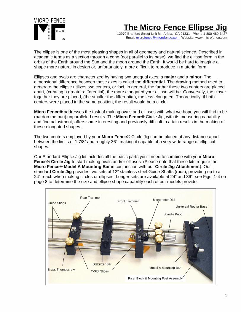
Our Standard Ellipse Jig kit includes all the basic parts you’ll need to combine with your MicroFence® Circle Jig to start making ovals and/or ellipses. (Please note that these kits require theMicro Fence® Model A Mounting Bar in conjunction with our Circle Jig Attachment ). Ourstandard Circle Jig provides two sets of 12” stainless steel Guide Shafts (rods), providing up to a24” reach when making circles or ellipses. Longer sets are available at 24” and 36”; see Figs. 1-4 onpage 8 to determine the size and ellipse shape capability each of our models provide.
1
Rear Trammel Front Trammel
Model A Mounting Bar Stabilizer Bar
Guide ShaftsMicrometer Dial
Riser Block & Mounting Post Assembly
T-Slot Slides
Universal Router Base
Brass Thumbscrew
Spindle Knob
The Micro F ence Ellipse Jig 12970 Branford Street Unit M, Arleta, CA 91331 Phone 1-800-480-6427
Email: [email protected] Website: www.microfence.com
Instructions for Set-up and Operation :
Before you begin, be sure to verify that you have received all parts that are checked off on thepacking list that is included with your Ellipse Jig.
Attaching Your Router to the Router Plate: Use your router’s factory sub-base as a template todrill the Ellipse Jig Router Base screw holes. Center the bit opening of the sub-base from your routerwith the one in the Router Plate to locate the screw hole positions. Take care to keep the bottom,with the countersunk holes, facing downward to insure an accurate alignment. (If the holes in yourrouter sub-base are not symmetrically placed, flipping the base can cause incorrect markings.) Toprotect the finish on your Router Plate, you can leave the protective plastic in place while you drill.Mark, drill, and countersink the Ellipse Jig Router Base to accommodate your router’s screwrequirements. Remove the protective plastic. (See the separate Universal Router Plate instructionpage for further information.)
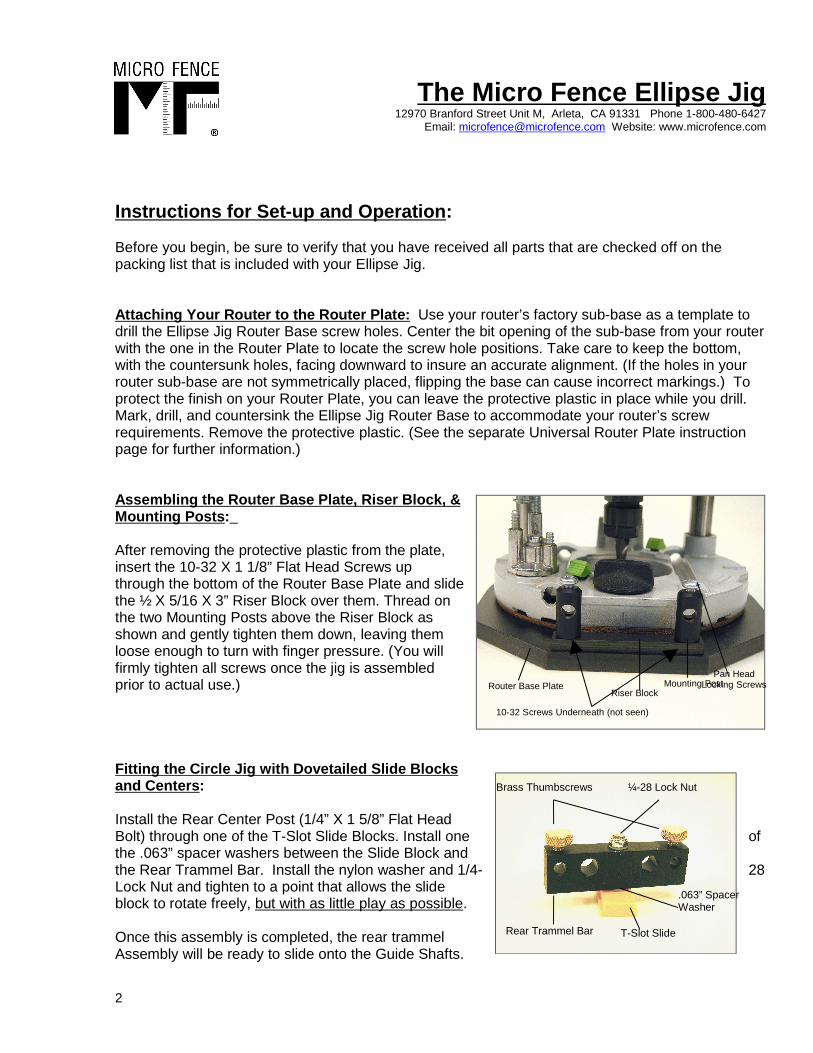
Assembling the Router Base Plate, Riser Block , & Mounting Posts :
After removing the protective plastic from the plate,insert the 10-32 X 1 1/8” Flat Head Screws upthrough the bottom of the Router Base Plate and slidethe ½ X 5/16 X 3” Riser Block over them. Thread onthe two Mounting Posts above the Riser Block asshown and gently tighten them down, leaving themloose enough to turn with finger pressure. (You willfirmly tighten all screws once the jig is assembledprior to actual use.)
Fitting the Circle Jig with Dovetailed Slide Blocksand Centers :
Install the Rear Center Post (1/4” X 1 5/8” Flat HeadBolt) through one of the T-Slot Slide Blocks. Install one ofthe .063” spacer washers between the Slide Block andthe Rear Trammel Bar. Install the nylon washer and 1/4- 28Lock Nut and tighten to a point that allows the slideblock to rotate freely, but with as little play as possible.
Once this assembly is completed, the rear trammelAssembly will be ready to slide onto the Guide Shafts.
2
Router Base PlateRiser Block
Mounting PostPan Head
Locking Screws
10-32 Screws Underneath (not seen)
T-Slot Slide
¼-28 Lock Nut
Rear Trammel Bar
Brass Thumbscrews
.063” SpacerWasher
The Micro F ence Ellipse Jig 12970 Branford Street Unit M, Arleta, CA 91331 Phone 1-800-480-6427
Email: [email protected] Website: www.microfence.com
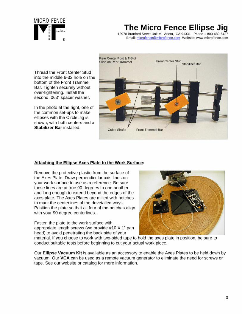
Thread the Front Center Studinto the middle 6-32 hole on thebottom of the Front TrammelBar. Tighten securely withoutover-tightening. Install thesecond .063” spacer washer.
In the photo at the right, one ofthe common set-ups to makeellipses with the Circle Jig isshown, with both centers and aStabilizer Bar installed.
Attaching the Ellipse Axes Plate to the Work Surfac e:
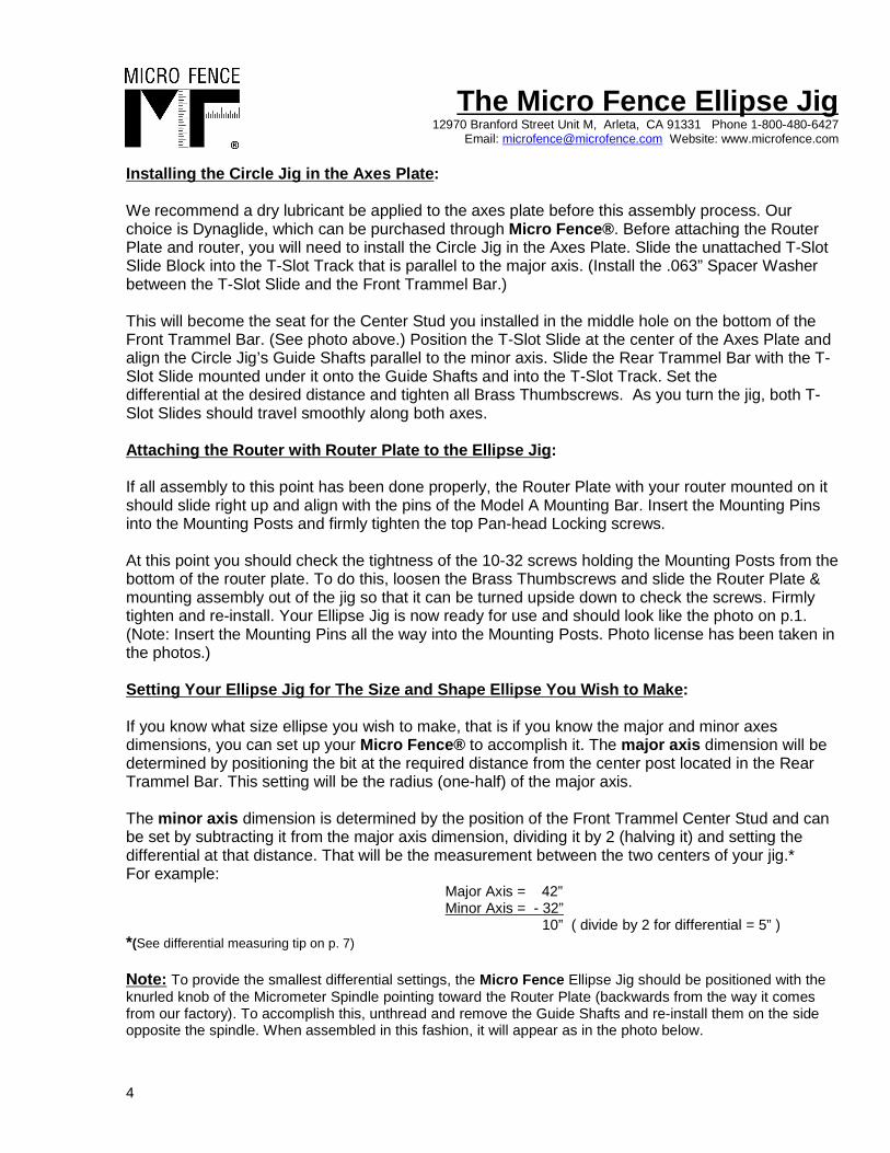
Remove the protective plastic from the surface ofthe Axes Plate. Draw perpendicular axis lines onyour work surface to use as a reference. Be surethese lines are at true 90 degrees to one anotherand long enough to extend beyond the edges of theaxes plate. The Axes Plates are milled with notchesto mark the centerlines of the dovetailed ways.Position the plate so that all four of the notches alignwith your 90 degree centerlines.
Fasten the plate to the work surface withappropriate length screws (we provide #10 X 1” panhead) to avoid penetrating the back side of yourmaterial. If you choose to work with two-sided tape to hold the axes plate in position, be sure toconduct suitable tests before beginning to cut your actual work piece.
Our Ellipse Vacuum Kit is available as an accessory to enable the Axes Plates to be held down byvacuum. Our VCA can be used as a remote vacuum generator to eliminate the need for screws ortape. See our website or catalog for more information.
3
Front Center Stud
Front Trammel Bar
Rear Center Post & T-SlotSlide on Rear Trammel
Stabilizer Bar
Guide Shafts
The Micro F ence Ellipse Jig 12970 Branford Street Unit M, Arleta, CA 91331 Phone 1-800-480-6427
Email: [email protected] Website: www.microfence.com
Installing the Circle Jig in the Axes Plate :
We recommend a dry lubricant be applied to the axes plate before this assembly process. Ourchoice is Dynaglide, which can be purchased through Micro Fence® . Before attaching the RouterPlate and router, you will need to install the Circle Jig in the Axes Plate. Slide the unattached T-SlotSlide Block into the T-Slot Track that is parallel to the major axis. (Install the .063” Spacer Washerbetween the T-Slot Slide and the Front Trammel Bar.)
This will become the seat for the Center Stud you installed in the middle hole on the bottom of theFront Trammel Bar. (See photo above.) Position the T-Slot Slide at the center of the Axes Plate andalign the Circle Jig’s Guide Shafts parallel to the minor axis. Slide the Rear Trammel Bar with the T-Slot Slide mounted under it onto the Guide Shafts and into the T-Slot Track. Set the differential at the desired distance and tighten all Brass Thumbscrews. As you turn the jig, both T-Slot Slides should travel smoothly along both axes.
Attaching the Router with Router Plate to the Ellip se Jig :
If all assembly to this point has been done properly, the Router Plate with your router mounted on itshould slide right up and align with the pins of the Model A Mounting Bar. Insert the Mounting Pinsinto the Mounting Posts and firmly tighten the top Pan-head Locking screws.
At this point you should check the tightness of the 10-32 screws holding the Mounting Posts from thebottom of the router plate. To do this, loosen the Brass Thumbscrews and slide the Router Plate &mounting assembly out of the jig so that it can be turned upside down to check the screws. Firmlytighten and re-install. Your Ellipse Jig is now ready for use and should look like the photo on p.1.(Note: Insert the Mounting Pins all the way into the Mounting Posts. Photo license has been taken inthe photos.)
Setting Your Ellipse Jig for The Size and Shape Ell ipse You Wish to Make :
If you know what size ellipse you wish to make, that is if you know the major and minor axesdimensions, you can set up your Micro Fence® to accomplish it. The major axis dimension will bedetermined by positioning the bit at the required distance from the center post located in the RearTrammel Bar. This setting will be the radius (one-half) of the major axis.
The minor axis dimension is determined by the position of the Front Trammel Center Stud and canbe set by subtracting it from the major axis dimension, dividing it by 2 (halving it) and setting thedifferential at that distance. That will be the measurement between the two centers of your jig.*For example: Major Axis = 42” Minor Axis = - 32” 10” ( divide by 2 for differential = 5” ) *(See differential measuring tip on p. 7)
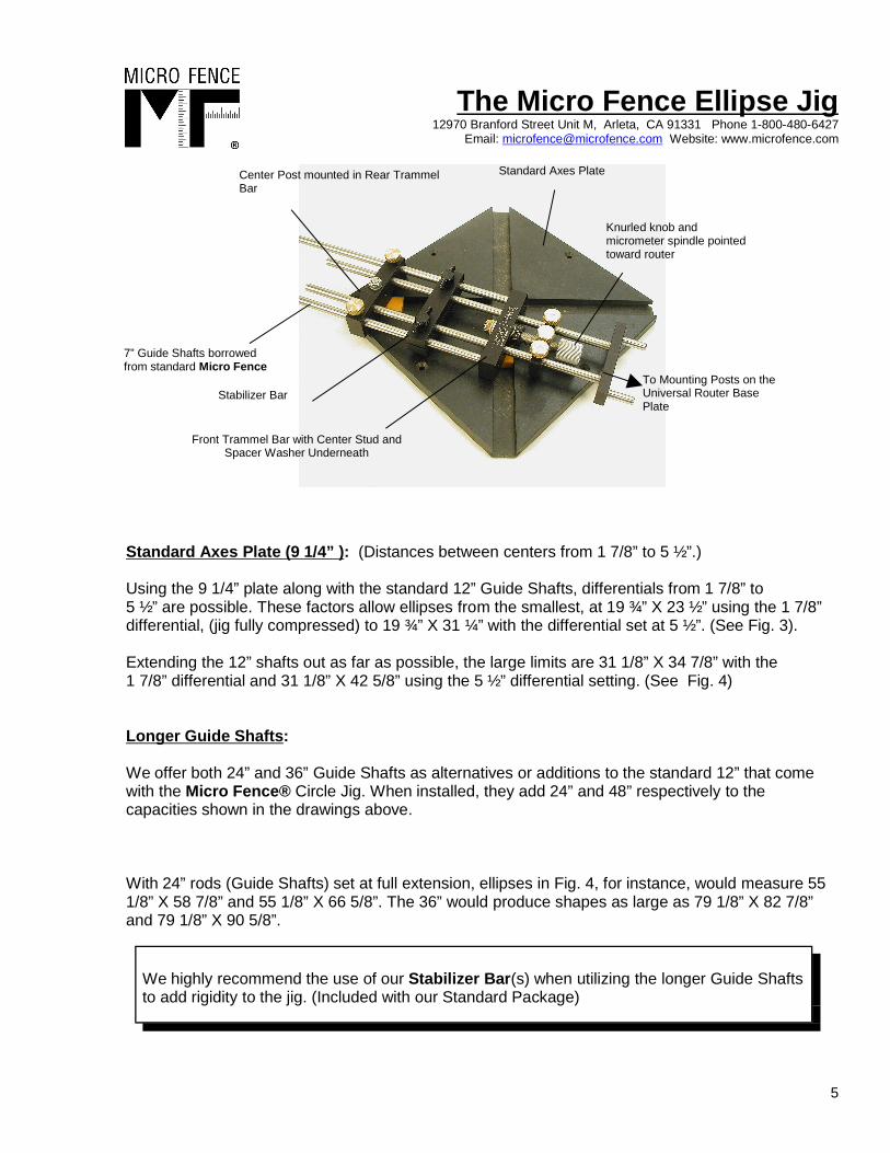
Note: To provide the smallest differential settings, the Micro Fence Ellipse Jig should be positioned with theknurled knob of the Micrometer Spindle pointing toward the Router Plate (backwards from the way it comesfrom our factory). To accomplish this, unthread and remove the Guide Shafts and re-install them on the sideopposite the spindle. When assembled in this fashion, it will appear as in the photo below.
4
The Micro F ence Ellipse Jig 12970 Branford Street Unit M, Arleta, CA 91331 Phone 1-800-480-6427
Email: [email protected] Website: www.microfence.com
Standard Axes Plate (9 1/4” ) : (Distances between centers from 1 7/8” to 5 ½”.)
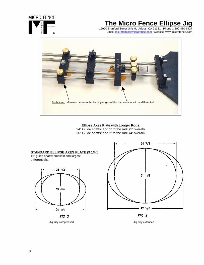
Using the 9 1/4” plate along with the standard 12” Guide Shafts, differentials from 1 7/8” to 5 ½” are possible. These factors allow ellipses from the smallest, at 19 ¾” X 23 ½” using the 1 7/8”differential, (jig fully compressed) to 19 ¾” X 31 ¼” with the differential set at 5 ½”. (See Fig. 3).
Extending the 12” shafts out as far as possible, the large limits are 31 1/8” X 34 7/8” with the 1 7/8” differential and 31 1/8” X 42 5/8” using the 5 ½” differential setting. (See Fig. 4)
Longer Guide Shafts :
We offer both 24” and 36” Guide Shafts as alternatives or additions to the standard 12” that comewith the Micro Fence® Circle Jig. When installed, they add 24” and 48” respectively to thecapacities shown in the drawings above.
With 24” rods (Guide Shafts) set at full extension, ellipses in Fig. 4, for instance, would measure 551/8” X 58 7/8” and 55 1/8” X 66 5/8”. The 36” would produce shapes as large as 79 1/8” X 82 7/8”and 79 1/8” X 90 5/8”.
5
We highly recommend the use of our Stabilizer Bar (s) when utilizing the longer Guide Shaftsto add rigidity to the jig. (Included with our Standard Package)
To Mounting Posts on theUniversal Router BasePlate
Standard Axes Plate
7” Guide Shafts borrowedfrom standard Micro Fence
Knurled knob andmicrometer spindle pointedtoward router
Center Post mounted in Rear TrammelBar
Stabilizer Bar
Front Trammel Bar with Center Stud andSpacer Washer Underneath
The Micro F ence Ellipse Jig 12970 Branford Street Unit M, Arleta, CA 91331 Phone 1-800-480-6427
Email: [email protected] Website: www.microfence.comLarger and/or More Elongated Ellipses with the T-Sl ot Tracks :
For larger ellipses and especially those that require large differential settings (such as those requiredfor transom windows or oval windows in entry doors), we offer T-Slot Track in 12”, 24”, and 48”lengths. These tracks come with both ends mitered and can be cut to any desired length to suit yourproject’s requirements. Drawing accurate axes lines on your work will assist you in your set up. Takecare to insure that these lines are drawn at true 90 degrees to one another and that they are markedclearly enough to be seen through the countersunk holes drilled along the centerline of the T-Slottrack.
Install two pieces of track along the major axis by placing the tips of the mitered ends against eachother and toward the center of your project. Align the holes drilled in the track with the center linedrawn on your work. Use a long straight edge or another of the T-Slot Tracks to help keep the firsttwo aligned. Note: A Vix Bit (self-centering pilot drill) can be an asset to help keep the screwstraight and centered for this installation.
Using a square, attach the remaining two tracks to the work surface. The alignment at the centerwhere the tracks meet is critical. Check to insure that there is no irregularity in track height. Shim tolevel if necessary.
Fit the Micro Fence® Circle Jig with the T-Slot Slide Block and both centers as described on page 2above. With the Rear Trammel Bar assembly removed, position the Front Center in the Slide Blockriding in the Major Axis Track. Slide the Rear Trammel Assembly into the Slide Block riding in theMinor Axis Track and fit the outside pair of Guide Shafts through the appropriate holes in theTrammel Bar. Adjust to the desired differential length and tighten the Brass Thumb Screws.
If you know the size of the ellipse you will be making, you can determine the length of track you willneed by dividing the axis size by 2 and then deducting the distance from your router bit to theinboard side of your Router Base Plate . (This assembly will have to pass by the end of the track.)If you are not sure of the size ellipse you want to make, temporarily attach the track to the worksurface in the manner described above and make a “dry run”. Determine whether or not the trackswill need to be cut and then mark and cut them off at the appropriate length. Be sure to save all cut-offs for future use.
Note : When making ellipses with larger differentials (more elongated ones), it‘s likely that it will benecessary to remove a Minor Axis Track section during the cutting process to allow the router andplate to pass by. Once you have completed that section of the cut, replace the track and continue.Repeat on the opposite side.
Our optional AXES TRACKS are available in 12”, 24”, and 48” lengths for larger and/or more elongatedellipses. These can be cut to any length to customize your jig and provide differentials to 30” plus. Werecommend our 4” T-Slot slides be used with the axes track for added rigidity.
6
Note: We recommend that you utilize as many of the counter-sunk screw holes aspossible to provide maximum rigidity for the slides.
The Micro F ence Ellipse Jig 12970 Branford Street Unit M, Arleta, CA 91331 Phone 1-800-480-6427
Email: [email protected] Website: www.microfence.com
Cutting Ellipses: Tips & Techniques :
• The success of your ellipse cutting will depend on your choice of router, the speed and feed ofyour cut execution as well as the rigidity of your Micro Fence® set-up, and your pre-cut planning.A little experimentation goes a long way toward understanding your set up, the character of thematerial you’re working with, and the performance of your equipment. We encourage test cuttingbefore each final application.
• Plan ahead for power cord management. A “dry run” before the cut may save costly errors. Werecommend suspending the cord from above with a flexible tie or recruiting a second pair of handsto help during the actual cutting process.
• Our router bit recommendation is for an up, down, or compression spiral. Some spiral bits offerchip-breaker grinds that are desirable when cutting hardwoods or composite materials. Our favoritebits are made by the Onsrud Company and we carry them in solid carbide. We also advise a littlespritz of dry lube, such as Dynaglide (our recommendation), on the router’s sub-base to reducefriction and/or resistance.
• We highly recommend the use of our Stabilizer Bar (s) to add rigidity to your Circle/Ellipse Jigin any set up. Install them whenever possible to insure best results with our equipment.
• Our Stop Collars can be used with your Circle/Ellipse Jig to memorize a cut position or to pre-set a second cut position. (Cases in point might be concentric cuts such as those required whenmaking curved moldings, when enlarging cuts to accommodate mating parts like inlays, or whencutting inside and outside diameters, e.g. rings.) These are available in sets of four from MicroFence® and feature nylon-tipped set screws that won’t harm the guide shafts when tighteneddown.
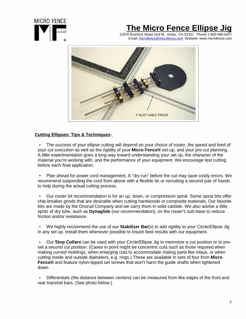
• Differentials (the distance between centers) can be measured from like edges of the front and
rear trammel bars. (See photo below.)
7
T-SLOT AXES TRACK
The Micro F ence Ellipse Jig 12970 Branford Street Unit M, Arleta, CA 91331 Phone 1-800-480-6427
Email: [email protected] Website: www.microfence.com
Ellipse Axes Plate with Longer Rods:24” Guide shafts: add 1’ to the radii (2’ overall)36” Guide shafts: add 2’ to the radii (4’ overall}
STANDARD ELLIPSE AXES PLATE (9 1/4”) 12” guide shafts; smallest and largest differentials.
8
Jig fully compressed Jig fully extended
Technique: Measure between the leading edges of the trammels to set the differential.