Embed Size (px)
Citation preview
MISTELIMINATORS
There are a number of factors in a process which may result in liquid entrainment. Some of the commonly
observed causes are discussed below.
Liquid entrainment may result from contact between gas and liquid phases in a mass transfer
operation or condensation process. For example droplets can result from bubbles bursting or jetting at
gas / liquid interface which is commonly seen in evaporators, bubble columns, distillation columns etc.
Droplets can also be formed by thermodynamic changes in the system. For example vapour
condenses when saturated gases are cooled in condensers and heat exchangers. The gas can become
supersaturated causing droplet formation
Also if the gas is travelling too fast to allow liquid droplets to settle at the under gravity they become
entrained in gas or vapour.
In most cases this entrainment must be removed to purify the gas and prevent process or environmental
contamination.
In the chemical process industry there are a number of processes where gases and liquids come into
contact with each other and whenever this happens the gas will entrain some amount of liquid particles.
This liquid phase which gets carried away into the gaseous phase can lead to a number of problems like
loss of product, equipment damage, process inefficiency etc. and needs to be eliminated.
Mist elimination can be defined as the mechanical separation of liquids from gases. The equipment used
for the removal of this entrainment is referred to as a mist eliminator or demister.
DROPLET FORMATION
MIST ELIMINATION
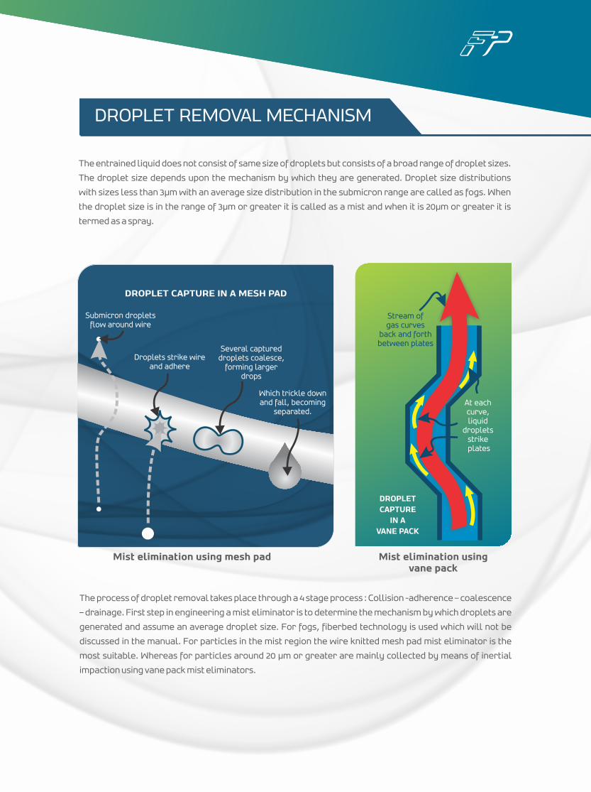
The entrained liquid does not consist of same size of droplets but consists of a broad range of droplet sizes.
The droplet size depends upon the mechanism by which they are generated. Droplet size distributions
with sizes less than 3µm with an average size distribution in the submicron range are called as fogs. When
the droplet size is in the range of 3µm or greater it is called as a mist and when it is 20µm or greater it is
termed as a spray.
The process of droplet removal takes place through a 4 stage process : Collision -adherence – coalescence
– drainage. First step in engineering a mist eliminator is to determine the mechanism by which droplets are
generated and assume an average droplet size. For fogs, fiberbed technology is used which will not be
discussed in the manual. For particles in the mist region the wire knitted mesh pad mist eliminator is the
most suitable. Whereas for particles around 20 µm or greater are mainly collected by means of inertial
impaction using vane pack mist eliminators.
Mist elimination using vane pack
DROPLET CAPTURE IN A MESH PAD
Droplets strike wireand adhere
Several captureddroplets coalesce,
forming largerdrops
Which trickle downand fall, becoming
separated.
Stream ofgas curves
back and forthbetween plates
At eachcurve,liquid
dropletsstrike plates
DROPLET CAPTURE
IN A VANE PACK
DROPLET REMOVAL MECHANISM
Mist elimination using mesh pad
Submicron dropletsflow around wire
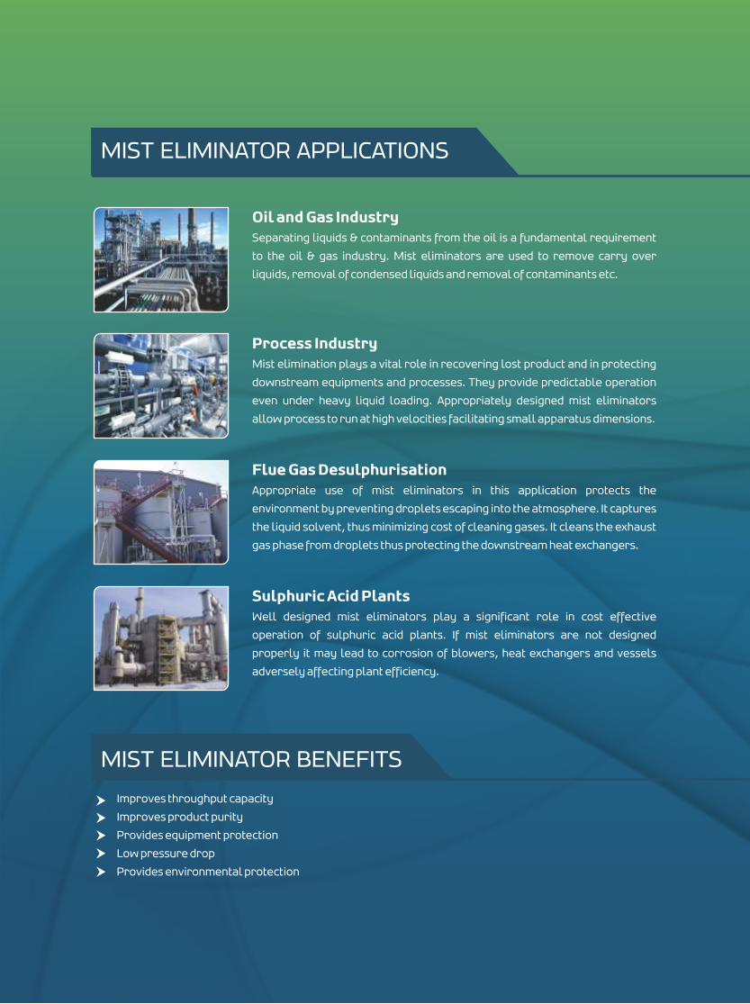
Improves throughput capacity
Improves product purity
Provides equipment protection
Low pressure drop
Provides environmental protection
MIST ELIMINATOR APPLICATIONS
Oil and Gas IndustrySeparating liquids & contaminants from the oil is a fundamental requirement
to the oil & gas industry. Mist eliminators are used to remove carry over
liquids, removal of condensed liquids and removal of contaminants etc.
Process IndustryMist elimination plays a vital role in recovering lost product and in protecting
downstream equipments and processes. They provide predictable operation
even under heavy liquid loading. Appropriately designed mist eliminators
allow process to run at high velocities facilitating small apparatus dimensions.
Flue Gas DesulphurisationAppropriate use of mist eliminators in this application protects the
environment by preventing droplets escaping into the atmosphere. It captures
the liquid solvent, thus minimizing cost of cleaning gases. It cleans the exhaust
gas phase from droplets thus protecting the downstream heat exchangers.
Sulphuric Acid PlantsWell designed mist eliminators play a significant role in cost effective
operation of sulphuric acid plants. If mist eliminators are not designed
properly it may lead to corrosion of blowers, heat exchangers and vessels
adversely affecting plant efficiency.
MIST ELIMINATOR BENEFITS
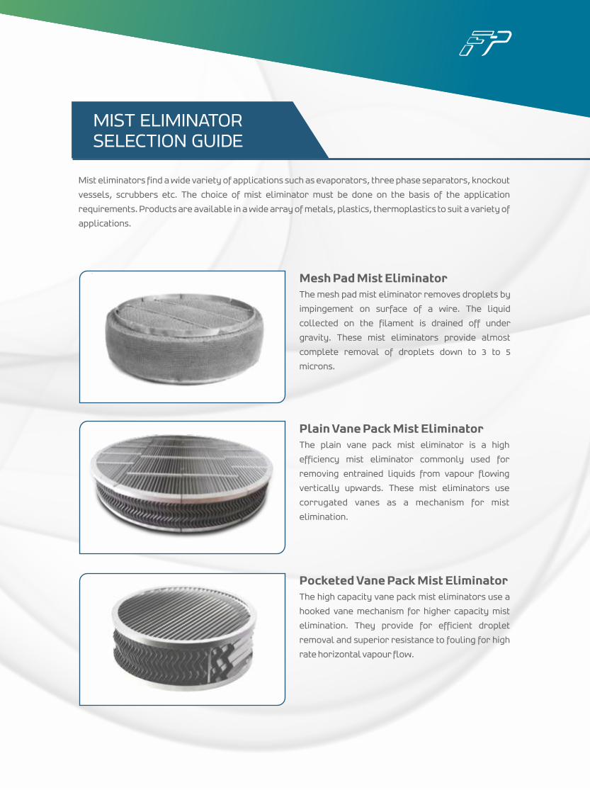
Mist eliminators find a wide variety of applications such as evaporators, three phase separators, knockout
vessels, scrubbers etc. The choice of mist eliminator must be done on the basis of the application
requirements. Products are available in a wide array of metals, plastics, thermoplastics to suit a variety of
applications.
MIST ELIMINATOR SELECTION GUIDE
Mesh Pad Mist EliminatorThe mesh pad mist eliminator removes droplets by
impingement on surface of a wire. The liquid
collected on the filament is drained off under
gravity. These mist eliminators provide almost
complete removal of droplets down to 3 to 5
microns.
Plain Vane Pack Mist EliminatorThe plain vane pack mist eliminator is a high
efficiency mist eliminator commonly used for
removing entrained liquids from vapour flowing
vertically upwards. These mist eliminators use
corrugated vanes as a mechanism for mist
elimination.
Pocketed Vane Pack Mist EliminatorThe high capacity vane pack mist eliminators use a
hooked vane mechanism for higher capacity mist
elimination. They provide for efficient droplet
removal and superior resistance to fouling for high
rate horizontal vapour flow.
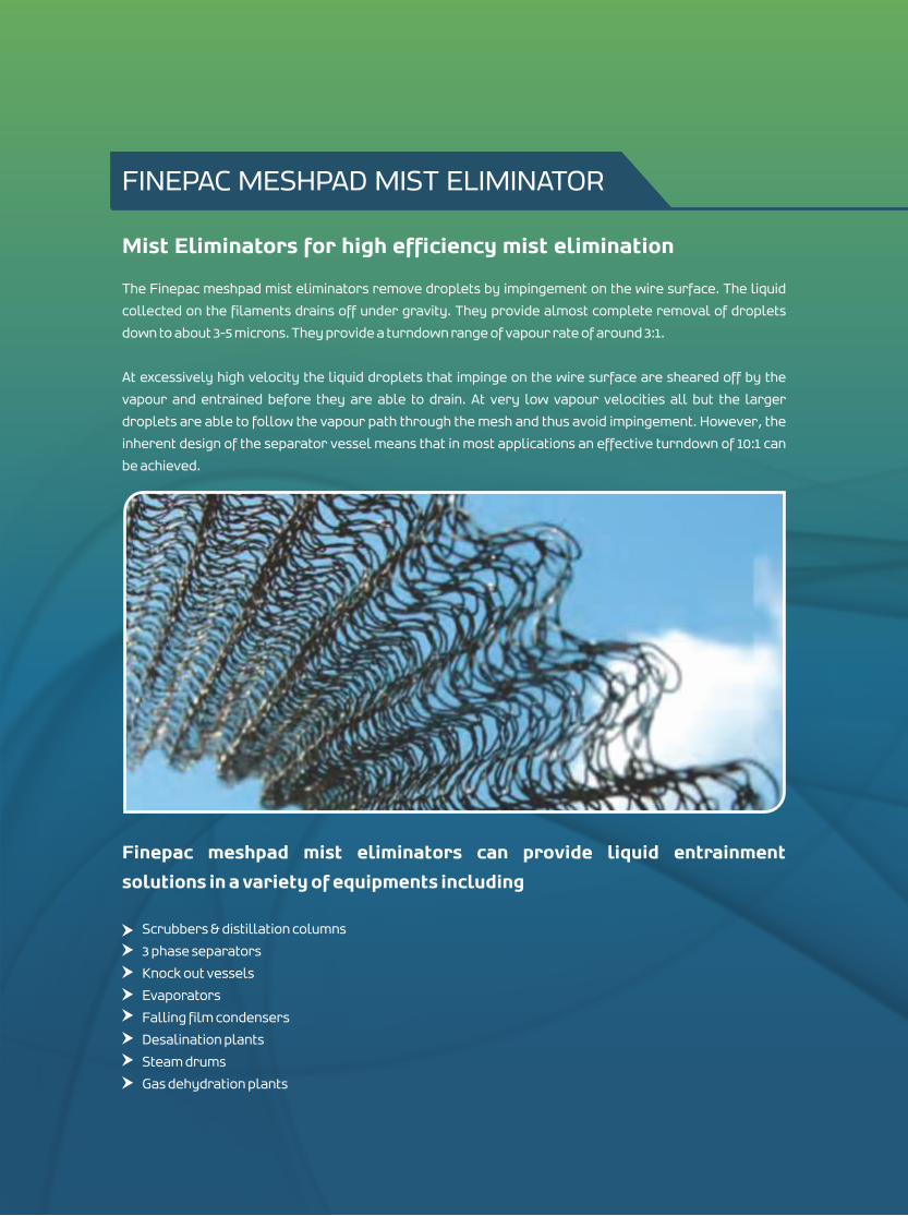
Mist Eliminators for high efficiency mist elimination
The Finepac meshpad mist eliminators remove droplets by impingement on the wire surface. The liquid
collected on the filaments drains off under gravity. They provide almost complete removal of droplets
down to about 3-5 microns. They provide a turndown range of vapour rate of around 3:1.
At excessively high velocity the liquid droplets that impinge on the wire surface are sheared off by the
vapour and entrained before they are able to drain. At very low vapour velocities all but the larger
droplets are able to follow the vapour path through the mesh and thus avoid impingement. However, the
inherent design of the separator vessel means that in most applications an effective turndown of 10:1 can
be achieved.
Finepac meshpad mist eliminators can provide liquid entrainment
solutions in a variety of equipments including
Scrubbers & distillation columns
3 phase separators
Knock out vessels
Evaporators
Falling film condensers
Desalination plants
Steam drums
Gas dehydration plants
FINEPAC MESHPAD MIST ELIMINATOR
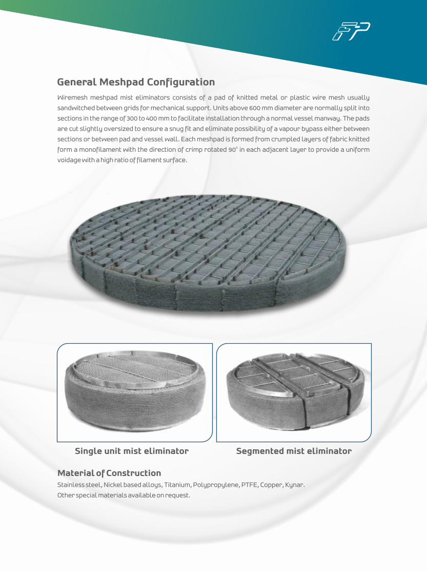
General Meshpad ConfigurationWiremesh meshpad mist eliminators consists of a pad of knitted metal or plastic wire mesh usually
sandwitched between grids for mechanical support. Units above 600 mm diameter are normally split into
sections in the range of 300 to 400 mm to facilitate installation through a normal vessel manway. The pads
are cut slightly oversized to ensure a snug fit and eliminate possibility of a vapour bypass either between
sections or between pad and vessel wall. Each meshpad is formed from crumpled layers of fabric knitted 0form a monofilament with the direction of crimp rotated 90 in each adjacent layer to provide a uniform
voidage with a high ratio of filament surface.
Material of ConstructionStainless steel, Nickel based alloys, Titanium, Polypropylene, PTFE, Copper, Kynar.
Other special materials available on request.
Single unit mist eliminator Segmented mist eliminator
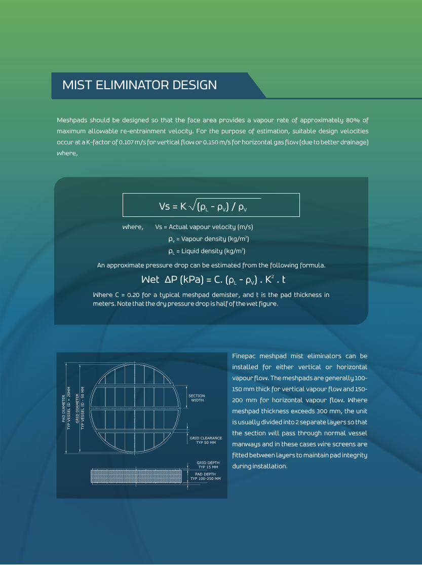
Meshpads should be designed so that the face area provides a vapour rate of approximately 80% of
maximum allowable re-entrainment velocity. For the purpose of estimation, suitable design velocities
occur at a K-factor of 0.107 m/s for vertical flow or 0.150 m/s for horizontal gas flow (due to better drainage)
where,
Finepac meshpad mist eliminators can be
installed for either vertical or horizontal
vapour flow. The meshpads are generally 100-
150 mm thick for vertical vapour flow and 150-
200 mm for horizontal vapour flow. Where
meshpad thickness exceeds 300 mm, the unit
is usually divided into 2 separate layers so that
the section will pass through normal vessel
manways and in these cases wire screens are
fitted between layers to maintain pad integrity
during installation.
Vs = K (ρ - ρ ) / ρL V V
where, Vs = Actual vapour velocity (m/s) 3ρ = Vapour density (kg/m ) v
3ρ = Liquid density (kg/m ) L
An approximate pressure drop can be estimated from the following formula.
2Wet ΔP (kPa) = C. (ρ - ρ ) . K . tL V
Where C = 0.20 for a typical meshpad demister, and t is the pad thickness in meters. Note that the dry pressure drop is half of the wet figure.
MIST ELIMINATOR DESIGN
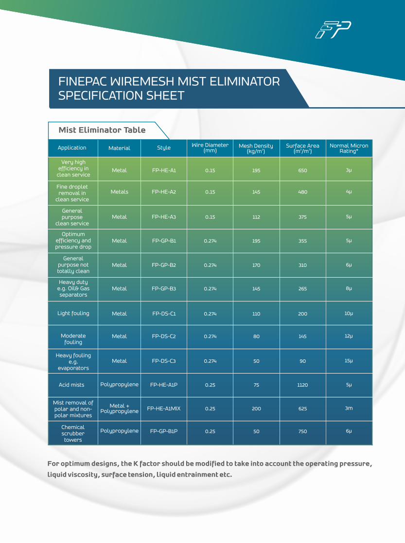
Application Material Style Wire Diameter (mm)
Mesh Density 3(kg/m )
Surface Area2 3(m /m )
Normal MicronRating*
Fine dropletremoval in
clean service
General purpose
clean service
General purpose not totally clean
Heavy duty e.g. Oil& Gas separators
Light fouling
Moderate fouling
Heavy fouling e.g.
evaporators
Acid mists
Mist removal of polar and non-polar mixtures
Chemical scrubbertowers
Metal
Metals
Metal
Metal
Metal
Metal
Metal
Metal
Metal
Polypropylene
Metal + Polypropylene
Polypropylene
FP-HE-A1
FP-HE-A2
FP-HE-A3
FP-GP-B1
FP-GP-B2
FP-GP-B3
FP-DS-C1
FP-DS-C2
FP-DS-C3
FP-HE-A1P
FP-HE-A1MIX
FP-GP-B1P
0.15
0.15
0.15
0.274
0.274
0.274
0.274
0.274
0.274
0.25
0.25
0.25
195
145
112
195
170
145
110
80
50
200
75
50
650
480
375
355
310
265
200
145
90
1120
625
750
3μ
4μ
5μ
5μ
6μ
8μ
10μ
12μ
15μ
5μ
3m
6μ
Very high efficiency in
clean service
Optimum efficiency and pressure drop
FINEPAC WIREMESH MIST ELIMINATOR SPECIFICATION SHEET
For optimum designs, the K factor should be modified to take into account the operating pressure,
liquid viscosity, surface tension, liquid entrainment etc.
Mist Eliminator Table
100
90
80
70
60
50
40
30
20
10
0
0 1 2 3 4 5 6 7 8 9 10 11 12 13 14 15 16 17 18 19 20
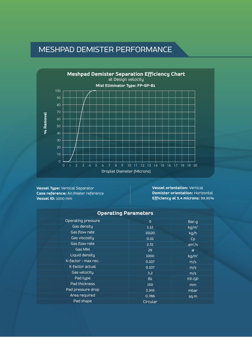
Meshpad Demister Separation Efficiency Chartat Design velocity
Mist Eliminator Type: FP-GP-B1
% R
em
ova
l
Droplet Diameter (Microns)
Operating pressure
Gas density
Gas flow rate
Gas viscosity
Gas flow rate
Gas MW
Liquid density
K-factor - max rec.
K-factor actual
Gas velocity
Pad type
Pad thickness
Pad pressure drop
Area required
Pad shape
Operating Parameters
Bar.g3kg/m
kg/h
Cp3am /s
#3kg/m
m/s
m/s
m/s
FP-GP
mm
mbar
sq.m
0
1.12
10120
0.01
2.51
29
1000
0.107
0.107
3.2
B1
150
3.345
0.786
Circular
Vessel Type: Vertical SeparatorCase reference: Air/Water referenceVessel ID: 1000 mm
Vessel orientation: VerticalDemister orientation: HorizontalEfficiency at 5.4 microns: 99.90%
MESHPAD DEMISTER PERFORMANCE
Operating pressure
Gas density
Gas flow rate
Gas viscosity
Gas flow rate
Gas MW
Liquid density
K-factor - max rec.
K-factor actual
Gas velocity
Pad type
Pad thickness
Pad pressure drop
Area required
Pad shape
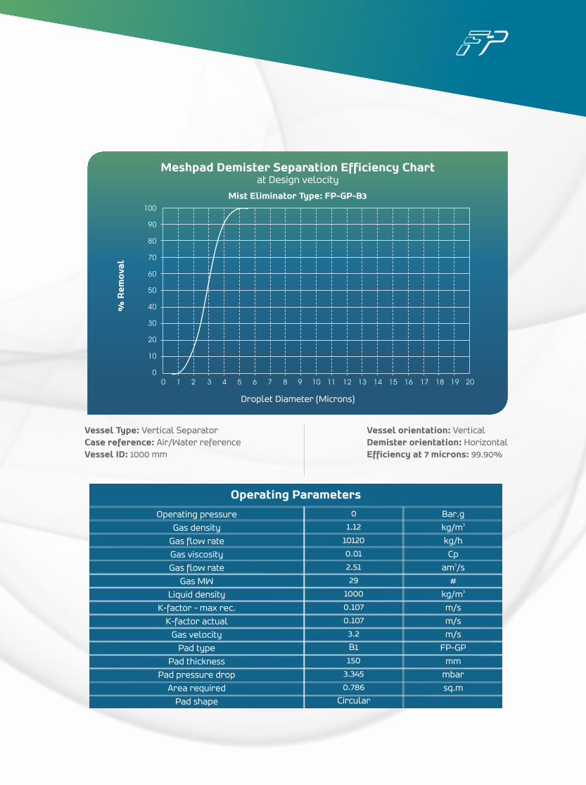
Operating Parameters
Bar.g3kg/m
kg/h
Cp3am /s
#3kg/m
m/s
m/s
m/s
FP-GP
mm
mbar
sq.m
0
1.12
10120
0.01
2.51
29
1000
0.107
0.107
3.2
B1
150
3.345
0.786
Circular
100
90
80
70
60
50
40
30
20
10
0
0 1 2 3 4 5 6 7 8 9 10 11 12 13 14 15 16 17 18 19 20
Meshpad Demister Separation Efficiency Chartat Design velocity
Mist Eliminator Type: FP-GP-B3
% R
em
ova
l
Vessel Type: Vertical SeparatorCase reference: Air/Water referenceVessel ID: 1000 mm
Vessel orientation: VerticalDemister orientation: HorizontalEfficiency at 7 microns: 99.90%
Droplet Diameter (Microns)
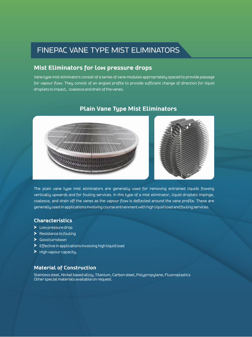
Vane type mist eliminators consist of a series of vane modules appropriately spaced to provide passage
for vapour flow. They consist of an angled profile to provide sufficient change of direction for liquid
droplets to impact, coalesce and drain of the vanes.
Mist Eliminators for low pressure drops
Plain Vane Type Mist Eliminators
The plain vane type mist eliminators are generally used for removing entrained liquids flowing
vertically upwards and for fouling services. In this type of a mist eliminator, liquid droplets impinge,
coalesce, and drain off the vanes as the vapour flow is deflected around the vane profile. These are
generally used in applications involving course entrainment with high liquid load and fouling services.
Characteristics Low pressure drop
Resistance to fouling
Good turndown
Effective in applications involving high liquid load
High vapour capacity.
Material of ConstructionStainless steel, Nickel based alloy, Titanium, Carbon steel, Polypropylene, FluoroplasticsOther special materials available on request.
FINEPAC VANE TYPE MIST ELIMINATORS
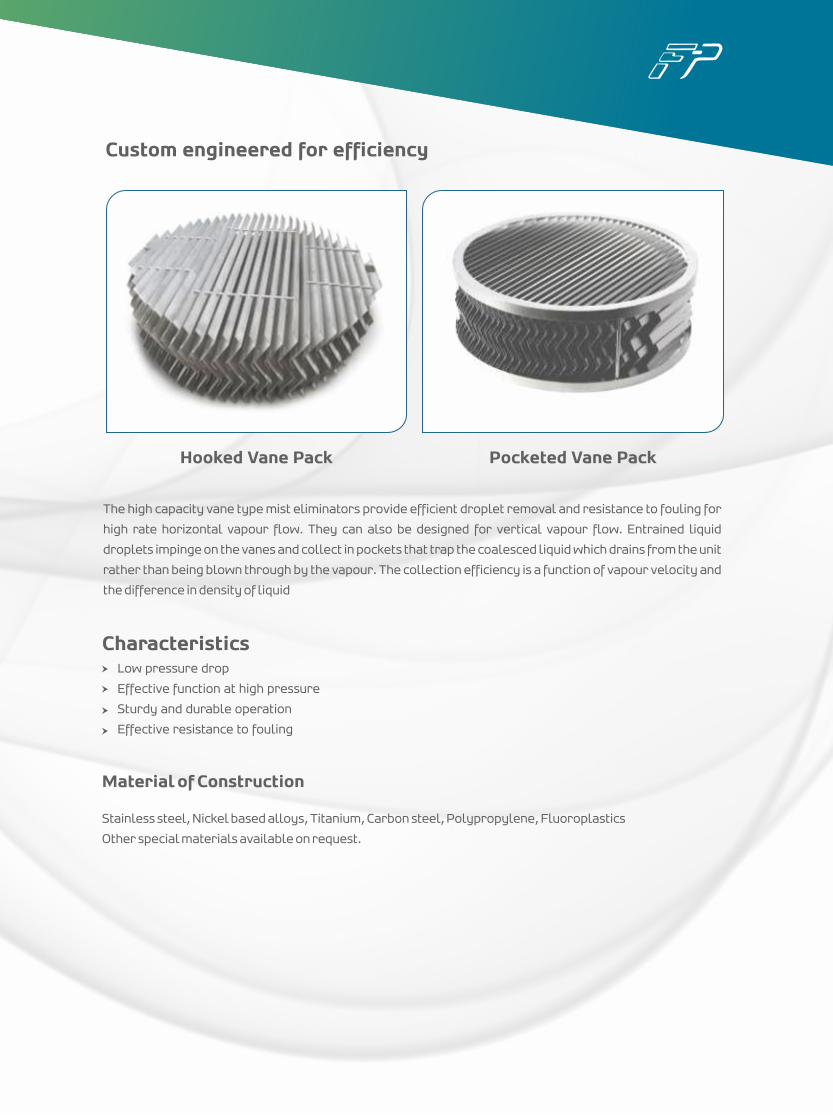
Custom engineered for efficiency
The high capacity vane type mist eliminators provide efficient droplet removal and resistance to fouling for
high rate horizontal vapour flow. They can also be designed for vertical vapour flow. Entrained liquid
droplets impinge on the vanes and collect in pockets that trap the coalesced liquid which drains from the unit
rather than being blown through by the vapour. The collection efficiency is a function of vapour velocity and
the difference in density of liquid
Hooked Vane Pack Pocketed Vane Pack
Material of Construction
Stainless steel, Nickel based alloys, Titanium, Carbon steel, Polypropylene, Fluoroplastics
Other special materials available on request.
CharacteristicsLow pressure drop
Effective function at high pressure
Sturdy and durable operation
Effective resistance to fouling
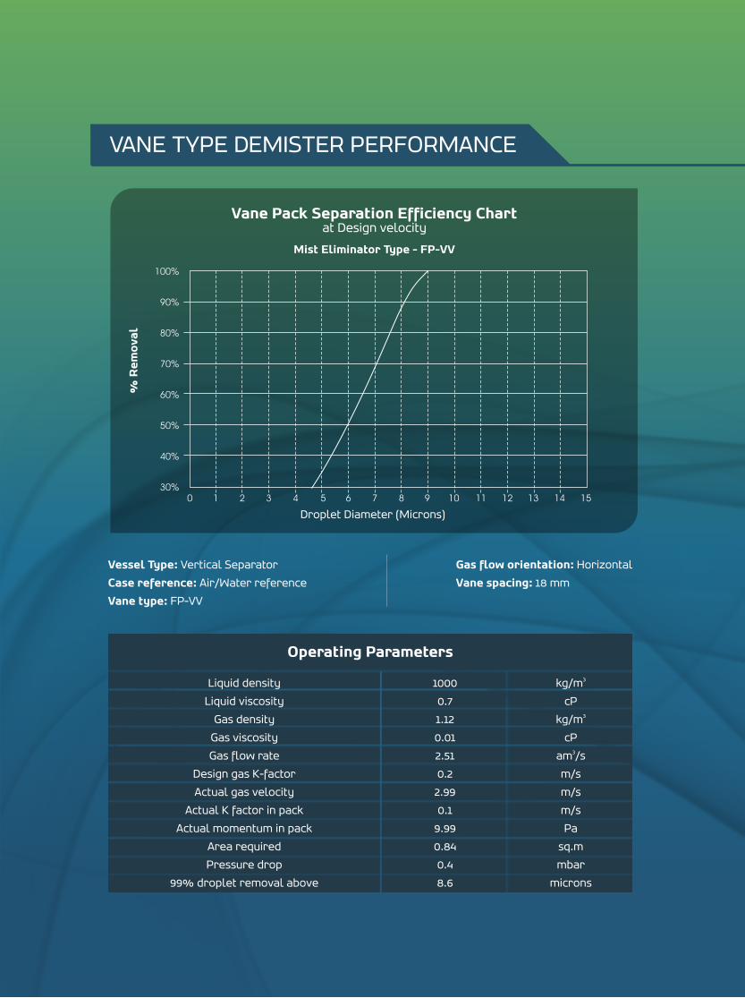
Liquid density
Liquid viscosity
Gas density
Gas viscosity
Gas flow rate
Design gas K-factor
Actual gas velocity
Actual K factor in pack
Actual momentum in pack
Area required
Pressure drop
99% droplet removal above
Operating Parameters
1000
0.7
1.12
0.01
2.51
0.2
2.99
0.1
9.99
0.84
0.4
8.6
3kg/m
cP3kg/m
cP3am /s
m/s
m/s
m/s
Pa
sq.m
mbar
microns
100%
90%
80%
70%
60%
50%
40%
30%
Vane Pack Separation Efficiency Chartat Design velocity
0 1 2 3 4 5 6 7 8 9 10 11 12 13 14 15
% R
em
ova
l
Mist Eliminator Type - FP-VV
Vessel Type: Vertical Separator
Case reference: Air/Water reference
Vane type: FP-VV
Gas flow orientation: Horizontal
Vane spacing: 18 mm
VANE TYPE DEMISTER PERFORMANCE
Droplet Diameter (Microns)
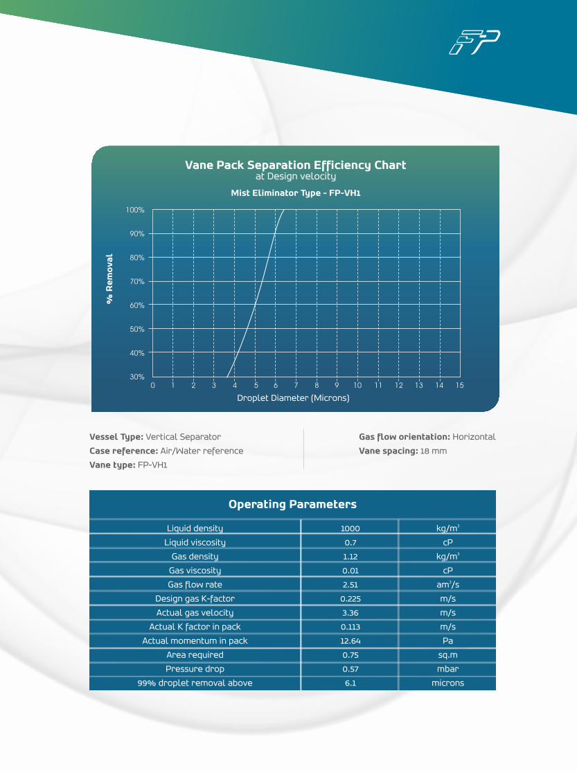
Liquid density
Liquid viscosity
Gas density
Gas viscosity
Gas flow rate
Design gas K-factor
Actual gas velocity
Actual K factor in pack
Actual momentum in pack
Area required
Pressure drop
99% droplet removal above
Operating Parameters
1000
0.7
1.12
0.01
2.51
0.225
3.36
0.113
12.64
0.75
0.57
6.1
3kg/m
cP3kg/m
cP3am /s
m/s
m/s
m/s
Pa
sq.m
mbar
microns
100%
90%
80%
70%
60%
50%
40%
30%
Vane Pack Separation Efficiency Chartat Design velocity
0 1 2 3 4 5 6 7 8 9 10 11 12 13 14 15
% R
em
ova
l
Mist Eliminator Type - FP-VH1
Vessel Type: Vertical Separator
Case reference: Air/Water reference
Vane type: FP-VH1
Gas flow orientation: Horizontal
Vane spacing: 18 mm
Droplet Diameter (Microns)

Head Office: S Block, J-25, MIDC, Bhosari, Pune 411026, INDIA. Tel: + 91 - 020 - 66120661 + 91 - 020 - 66120665 Fax: + 91 - 020 - 27119512.
Mumbai Office: ndBlock No. 1, 2 floor,
Navjivan Society Bldg No.3, Lamington Road, Mumbai 400008, INDIATel: + 91 80809 37166Fax: + 91 - 022-66648424
Hyderabad Office: 404, The LegendHouse number 2-2-11, Near Osmania University, D.D ColonyHyderabad 500 007, INDIA
UAE Office: Office no: E-46G,Hamriyah Free Trade Zone,Sharjah, United Arab EmiratesTel:
w w w . f i n e p a c i n d i a . i n
+971 5039 34769+971 5681 29036