Embed Size (px)
Citation preview
1
Electronics course part 2:
● Electronic noise● Electromagnetic interference ● Spectral analysis
ETHZ / LPC / Alexander Däpp / 2018
2
Noise
● Random fluctuations amplitude
● Ideal „white noise“ gaussian amplitude distribution
● Broad spectrum
● Noise averaging
SNR∝√N
3
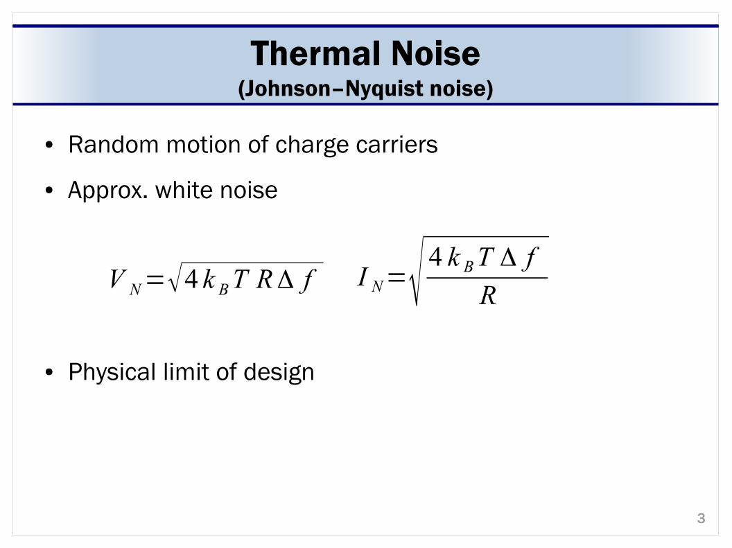
Thermal Noise(Johnson–Nyquist noise)
● Random motion of charge carriers
● Approx. white noise
● Physical limit of design
V N=√4 k BT RΔ f I N=√ 4 k BT Δ f
R
4
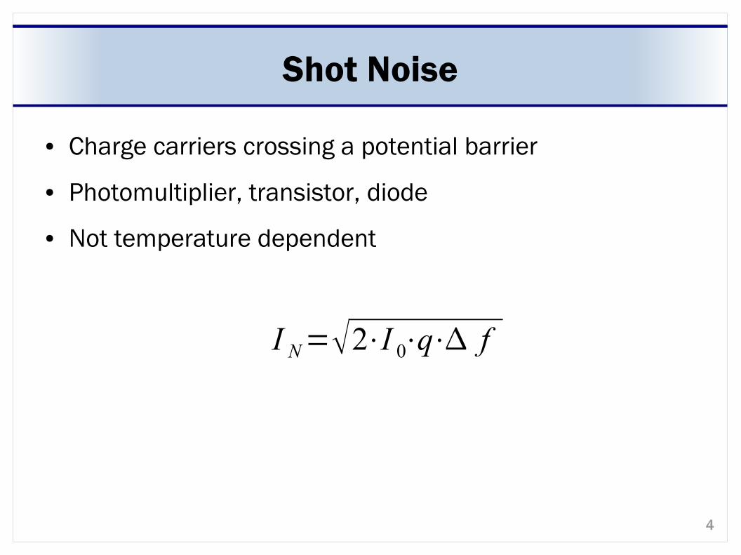
Shot Noise
● Charge carriers crossing a potential barrier
● Photomultiplier, transistor, diode
● Not temperature dependent
I N=2⋅I 0⋅q⋅ f
5
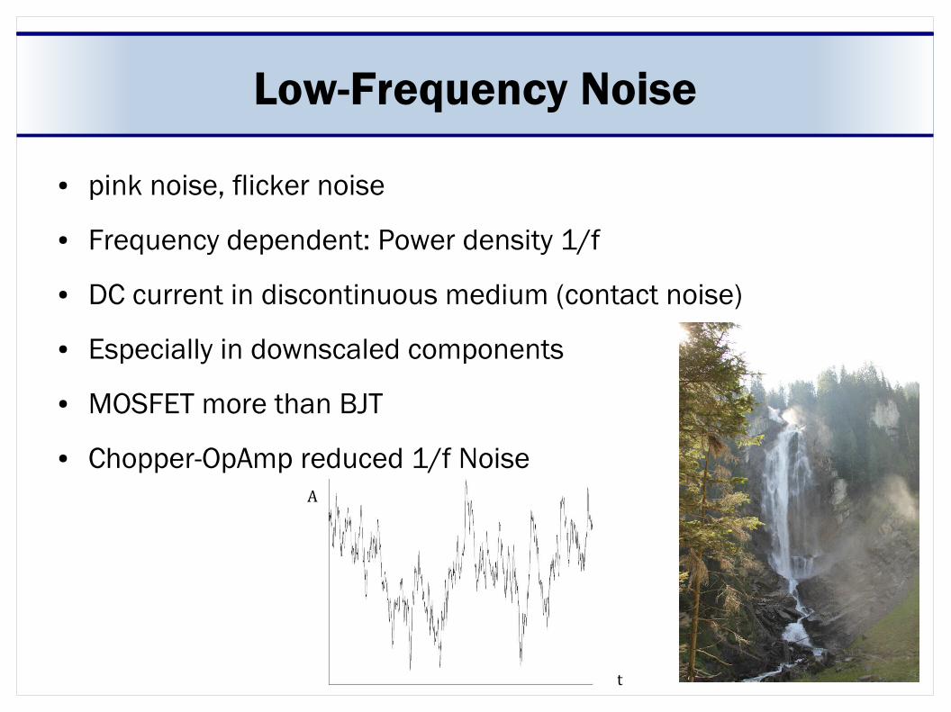
Low-Frequency Noise
● pink noise, flicker noise
● Frequency dependent: Power density 1/f
● DC current in discontinuous medium (contact noise)
● Especially in downscaled components
● MOSFET more than BJT
● Chopper-OpAmp reduced 1/f Noise
t
A
6
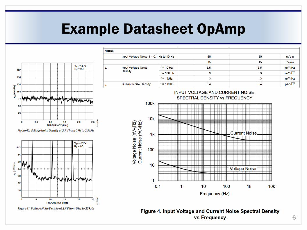
Example Datasheet OpAmp
7
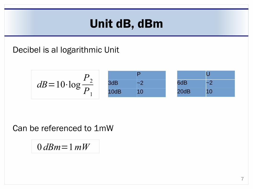
Unit dB, dBm
Decibel is al logarithmic Unit
Can be referenced to 1mW
dB=10⋅logP2P1
P
3dB ~2
10dB 10
U
6dB ~2
20dB 10
0dBm=1mW
8
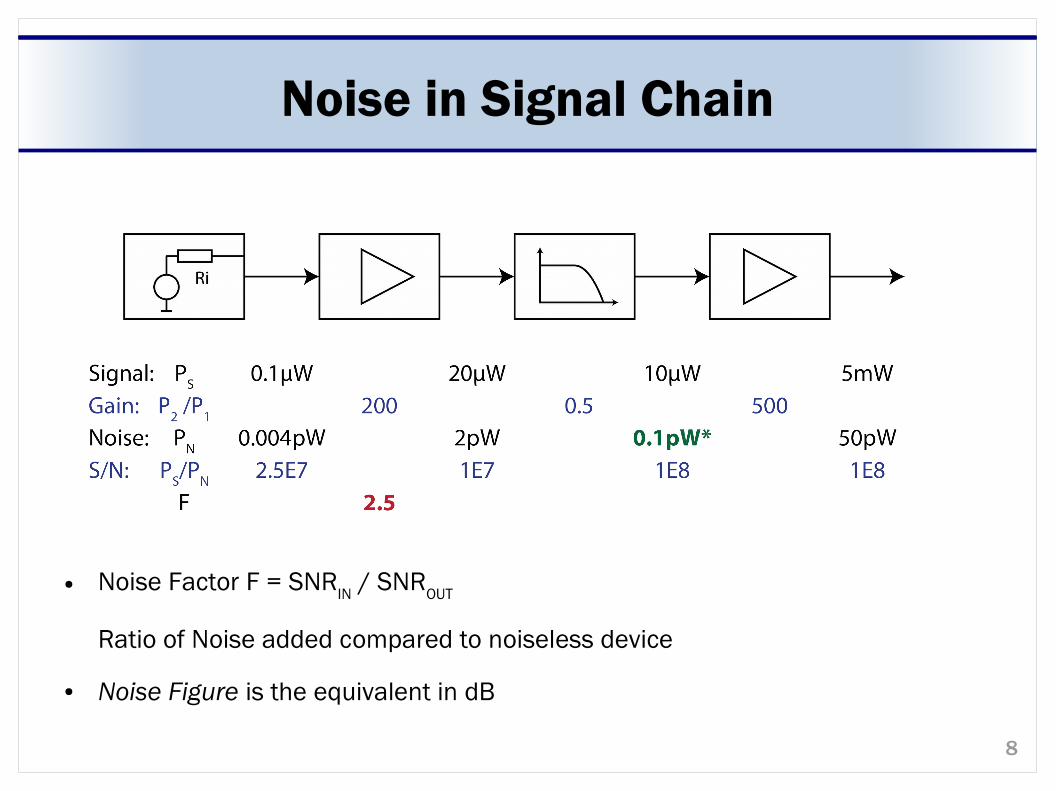
Noise in Signal Chain
● Noise Factor F = SNRIN
/ SNROUT
Ratio of Noise added compared to noiseless device
● Noise Figure is the equivalent in dB
9
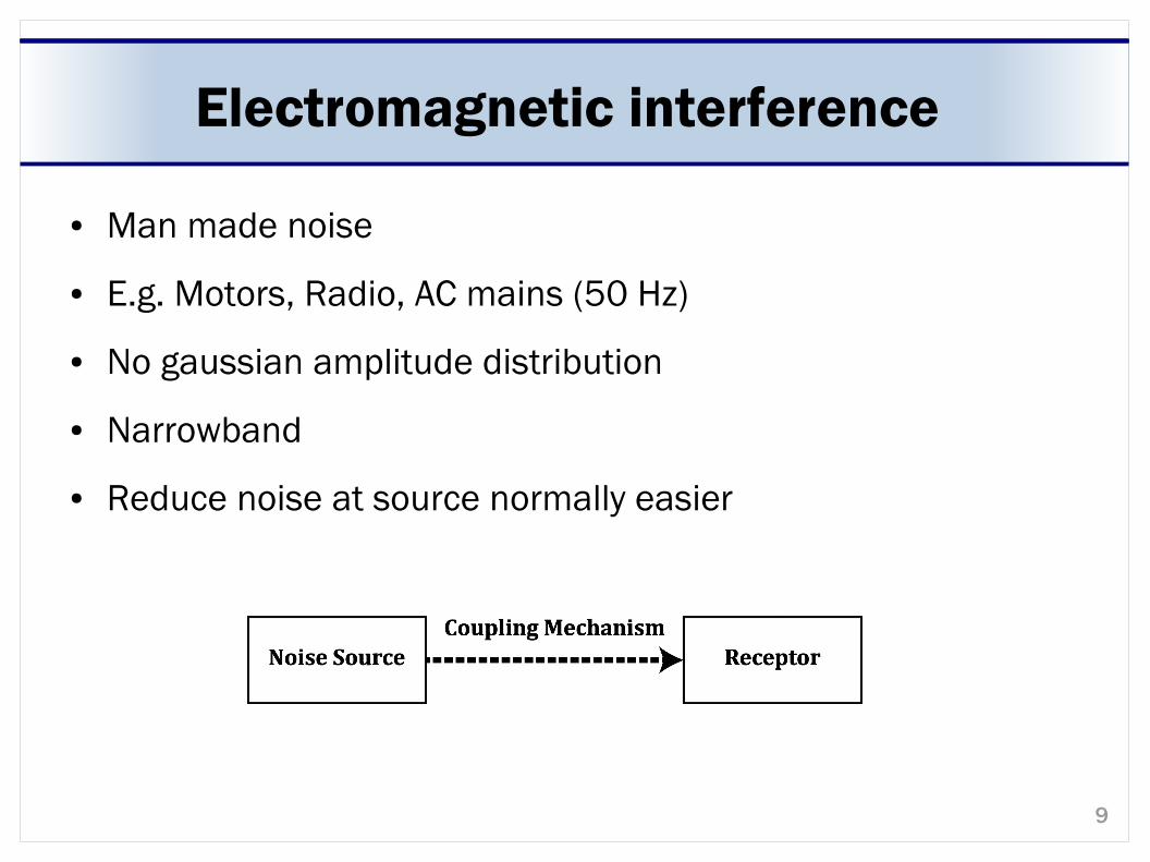
Electromagnetic interference
● Man made noise
● E.g. Motors, Radio, AC mains (50 Hz)
● No gaussian amplitude distribution
● Narrowband
● Reduce noise at source normally easier
10
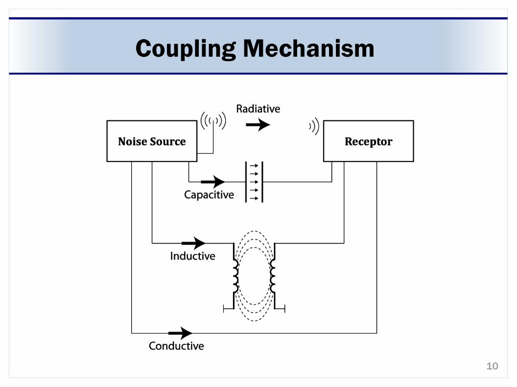
Coupling Mechanism
11
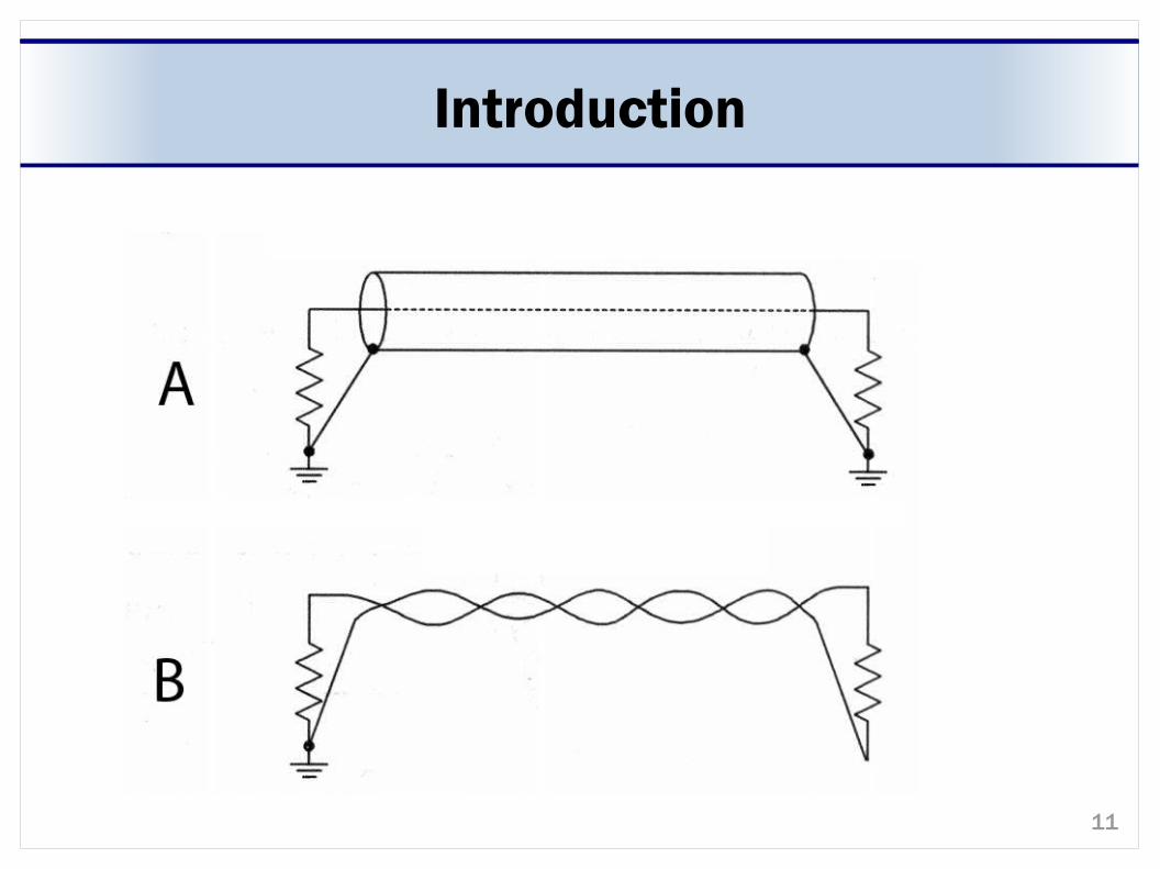
Introduction
12
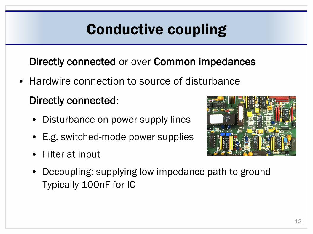
Conductive coupling
Directly connected or over Common impedances
● Hardwire connection to source of disturbance
Directly connected:
● Disturbance on power supply lines
● E.g. switched-mode power supplies
● Filter at input
● Decoupling: supplying low impedance path to ground Typically 100nF for IC
13
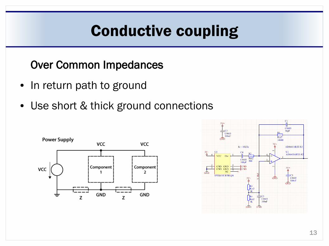
Conductive coupling
Over Common Impedances
● In return path to ground
● Use short & thick ground connections
14
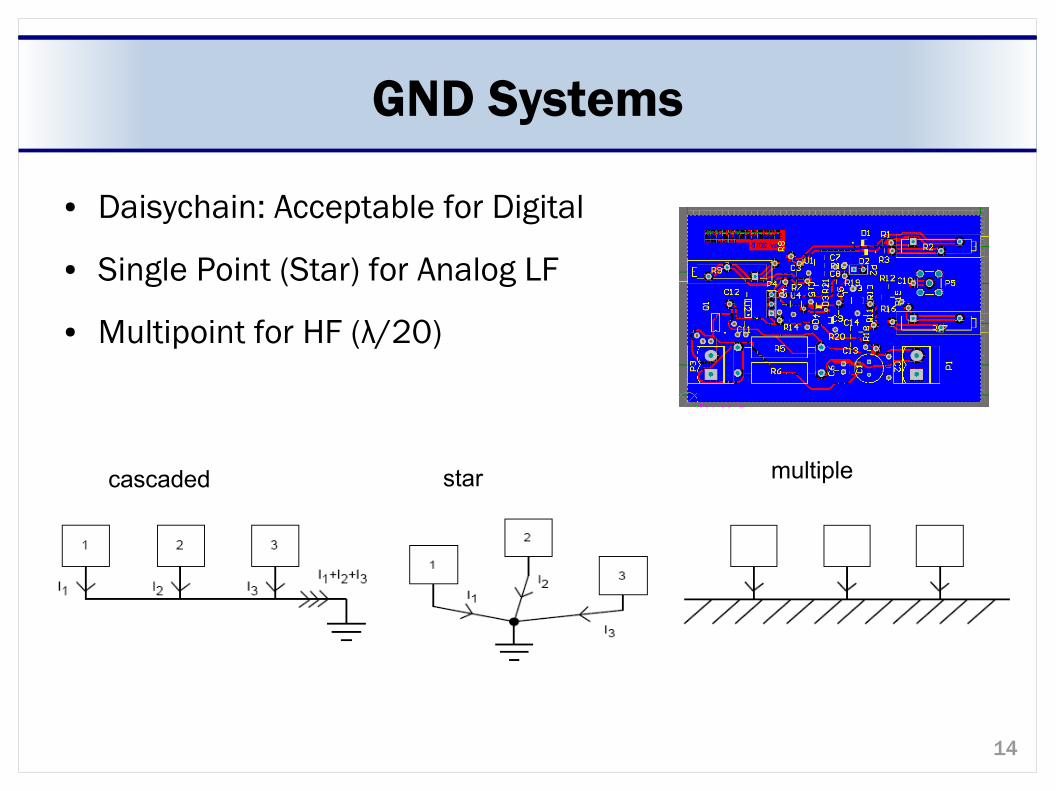
GND Systems
● Daisychain: Acceptable for Digital
● Single Point (Star) for Analog LF
● Multipoint for HF (λ/20)
starcascaded multiple
15
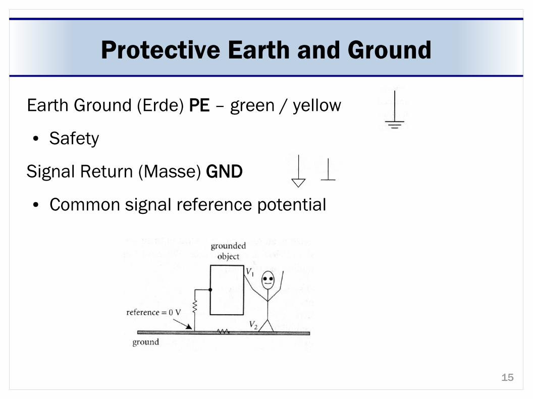
Protective Earth and Ground
Earth Ground (Erde) PE – green / yellow
● Safety
Signal Return (Masse) GND
● Common signal reference potential
16
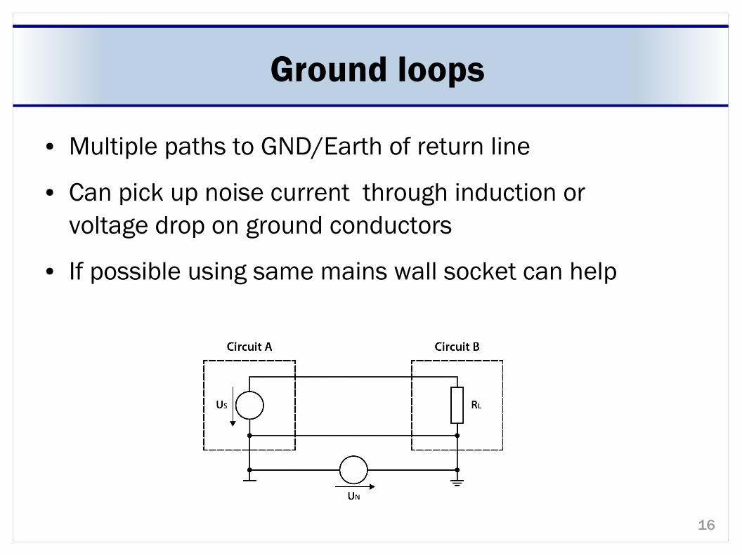
Ground loops
● Multiple paths to GND/Earth of return line
● Can pick up noise current through induction or voltage drop on ground conductors
● If possible using same mains wall socket can help
17
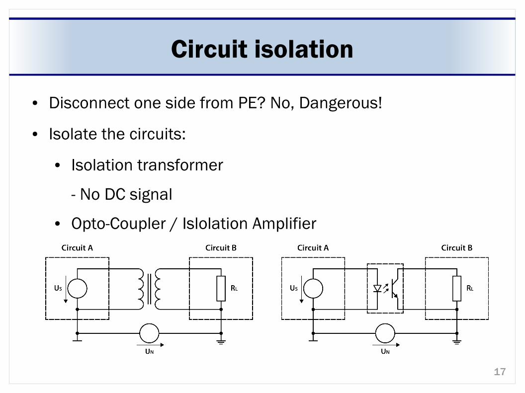
Circuit isolation
● Disconnect one side from PE? No, Dangerous!
● Isolate the circuits:
● Isolation transformer
- No DC signal
● Opto-Coupler / Islolation Amplifier
18
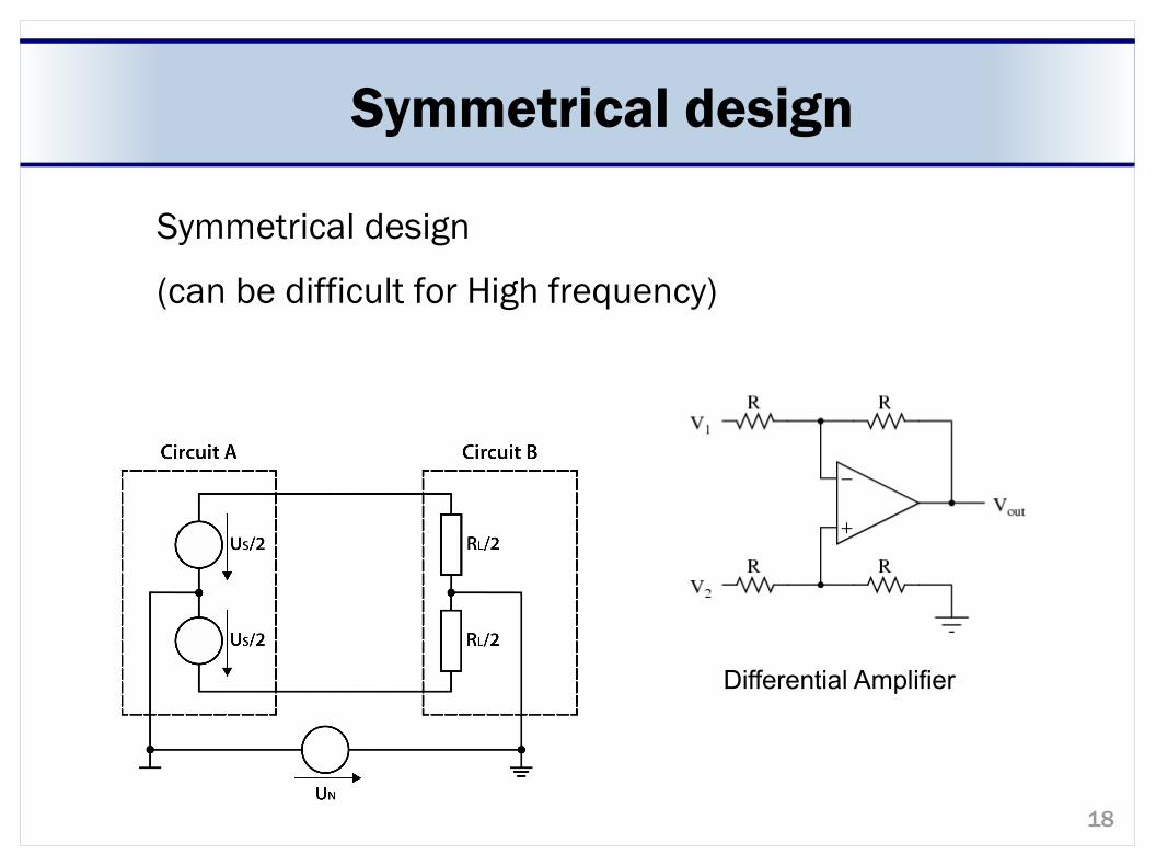
Symmetrical design
Symmetrical design
(can be difficult for High frequency)
Differential Amplifier
19
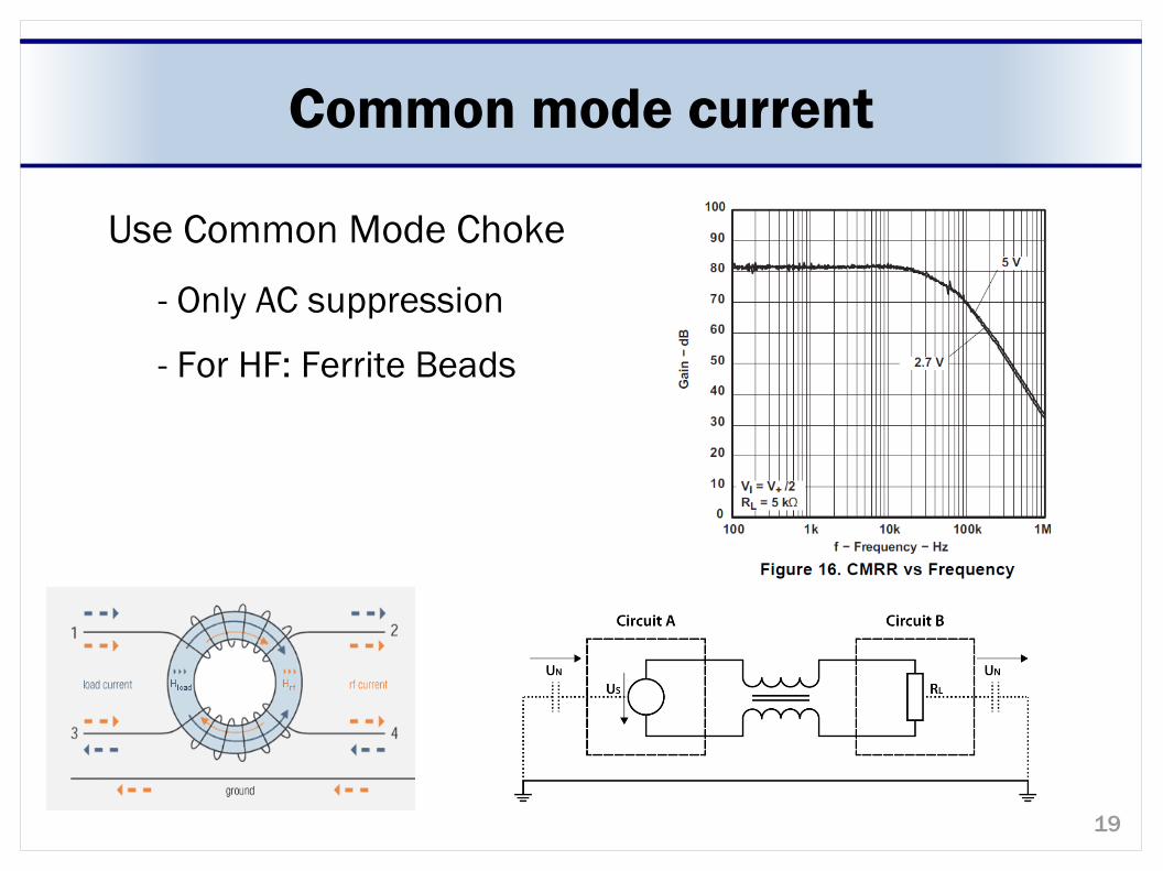
Common mode current
Use Common Mode Choke
- Only AC suppression
- For HF: Ferrite Beads
20
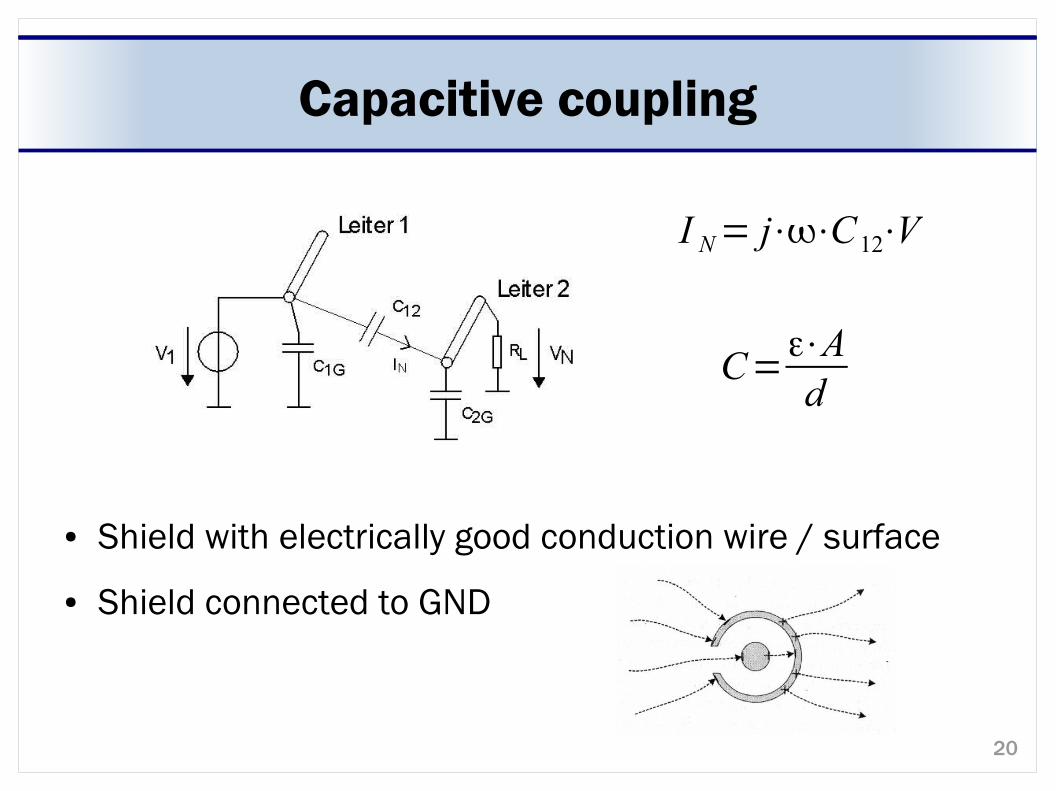
Capacitive coupling
● Shield with electrically good conduction wire / surface
● Shield connected to GND
I N= j⋅⋅C12⋅V
C=ε⋅Ad
21
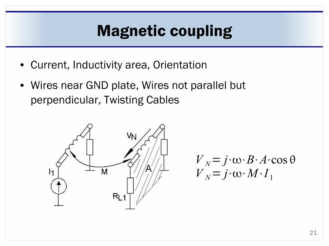
Magnetic coupling
● Current, Inductivity area, Orientation
● Wires near GND plate, Wires not parallel but perpendicular, Twisting Cables
V N= j⋅⋅B⋅A⋅cosV N= j⋅⋅M⋅I 1
22
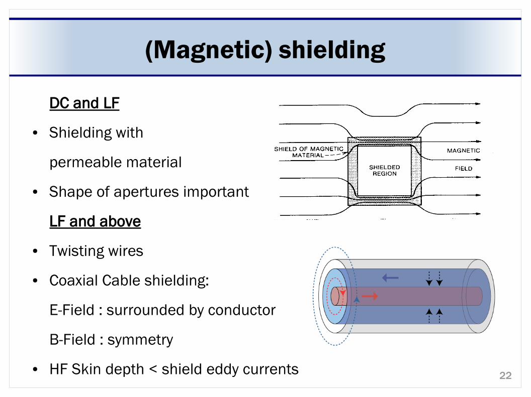
(Magnetic) shielding
DC and LF
● Shielding with
permeable material
● Shape of apertures important
LF and above
● Twisting wires
● Coaxial Cable shielding:
E-Field : surrounded by conductor
B-Field : symmetry
● HF Skin depth < shield eddy currents
23
EM coupling / radiation
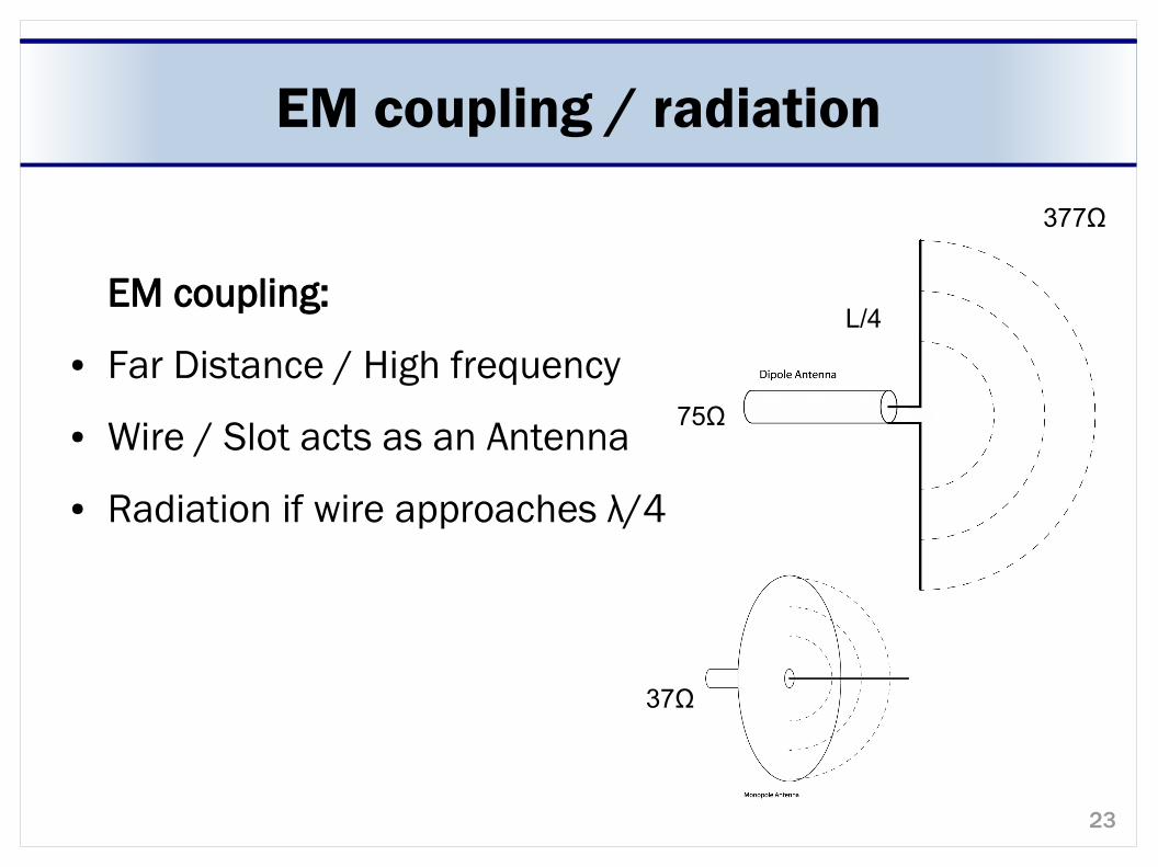
EM coupling:
● Far Distance / High frequency
● Wire / Slot acts as an Antenna
● Radiation if wire approaches λ/4
377Ω
75Ω
37Ω
L/4
24
EM coupling / radiation
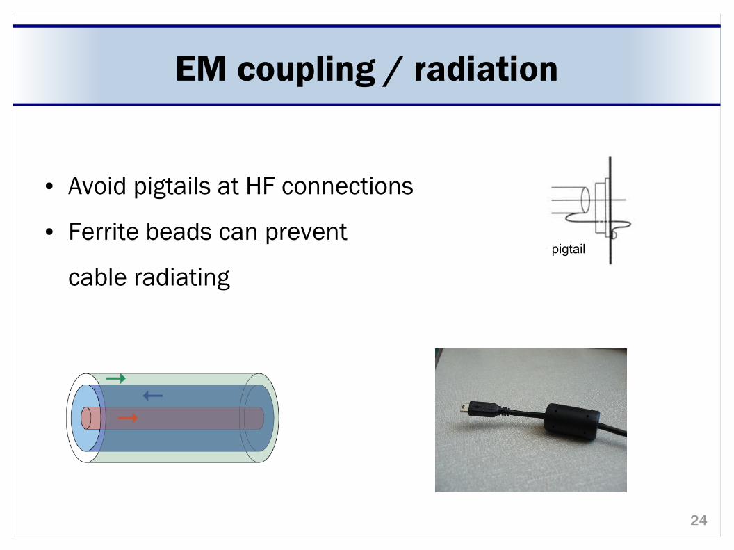
● Avoid pigtails at HF connections
● Ferrite beads can prevent
cable radiating
pigtail
25
Shielding Material
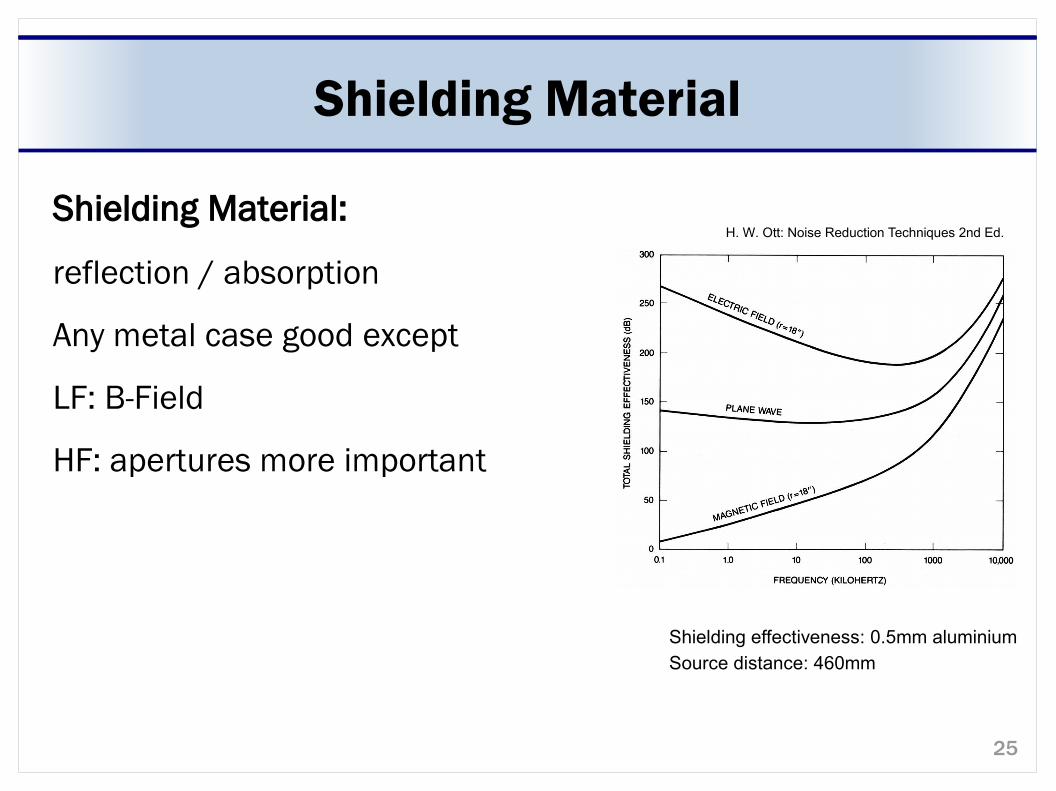
Shielding Material:
reflection / absorption
Any metal case good except
LF: B-Field
HF: apertures more important
Shielding effectiveness: 0.5mm aluminium
Source distance: 460mm
H. W. Ott: Noise Reduction Techniques 2nd Ed.
26
Filtering
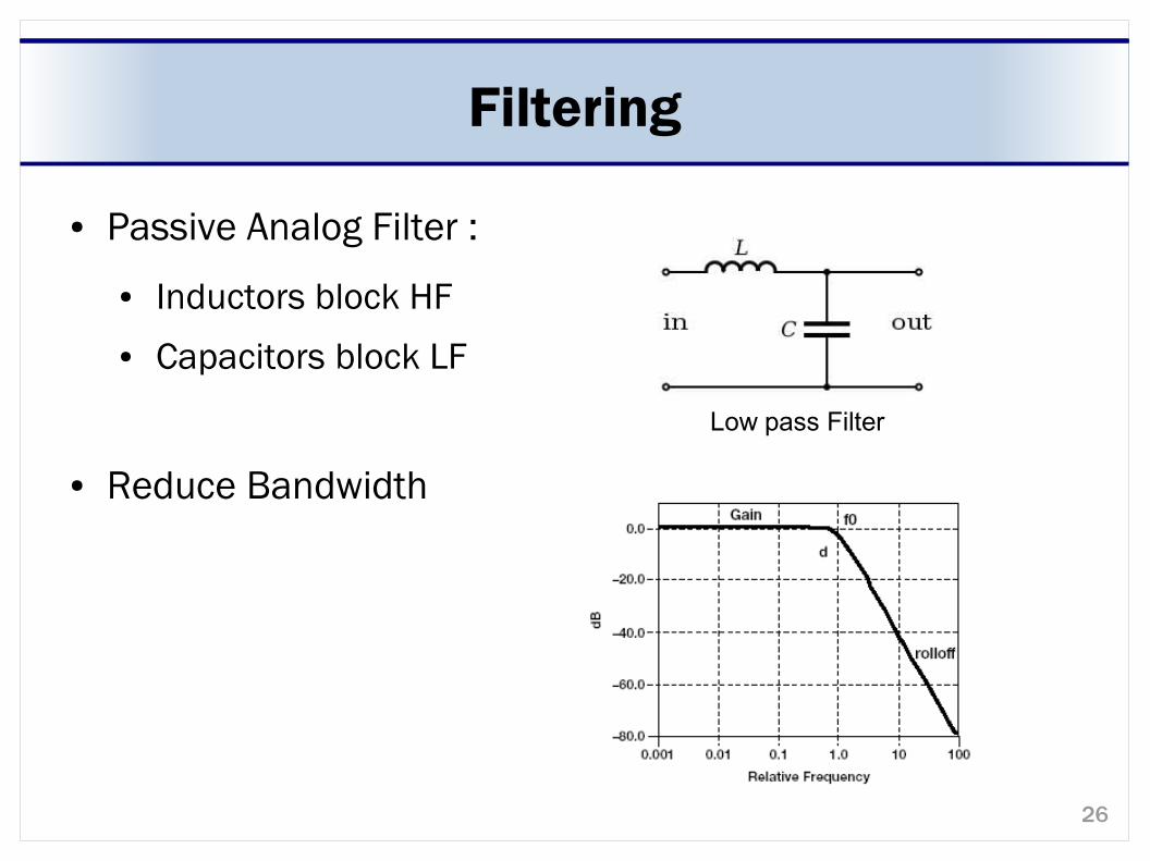
● Passive Analog Filter :
● Inductors block HF ● Capacitors block LF
● Reduce Bandwidth
Low pass Filter
27
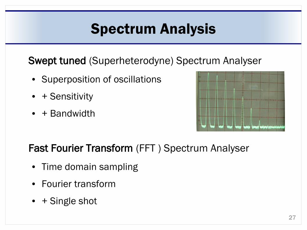
Spectrum Analysis
Swept tuned (Superheterodyne) Spectrum Analyser
● Superposition of oscillations
● + Sensitivity
● + Bandwidth
Fast Fourier Transform (FFT ) Spectrum Analyser
● Time domain sampling
● Fourier transform
● + Single shot
28
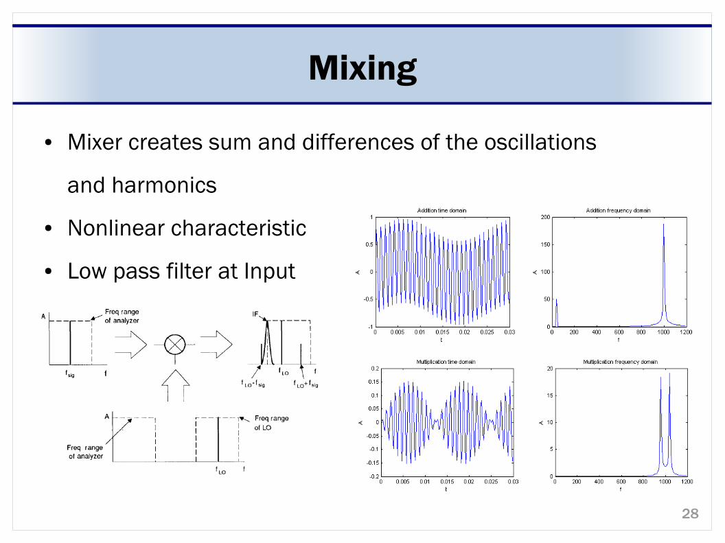
Mixing
● Mixer creates sum and differences of the oscillations
and harmonics
● Nonlinear characteristic
● Low pass filter at Input
29
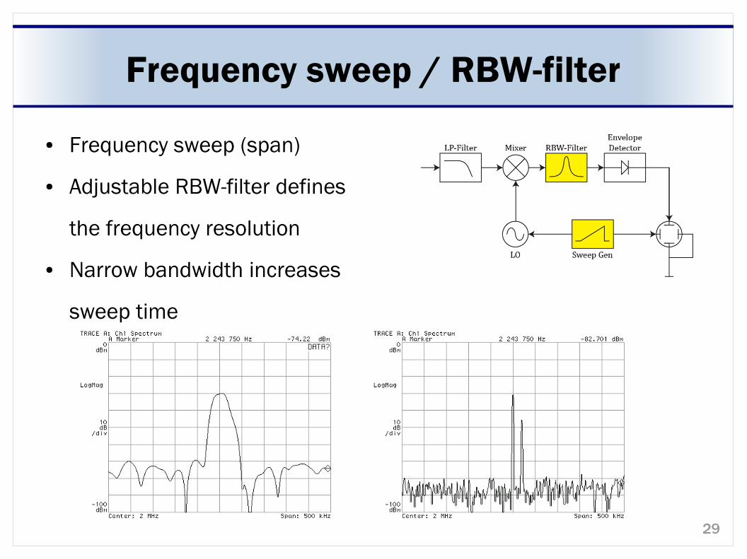
Frequency sweep / RBW-filter
● Frequency sweep (span)
● Adjustable RBW-filter defines
the frequency resolution
● Narrow bandwidth increases
sweep time
30
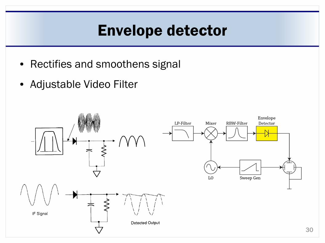
Envelope detector
● Rectifies and smoothens signal
● Adjustable Video Filter
31
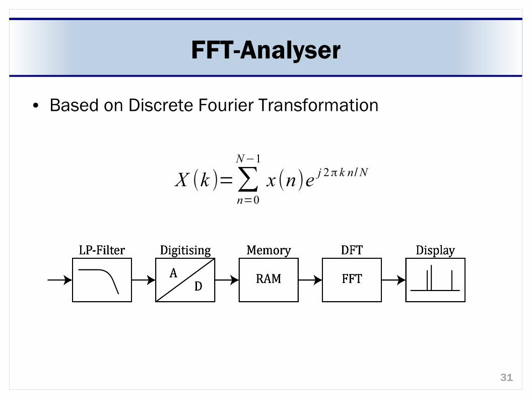
FFT-Analyser
● Based on Discrete Fourier Transformation
X (k )=∑n=0
N−1
x (n)e j 2π k n /N
32
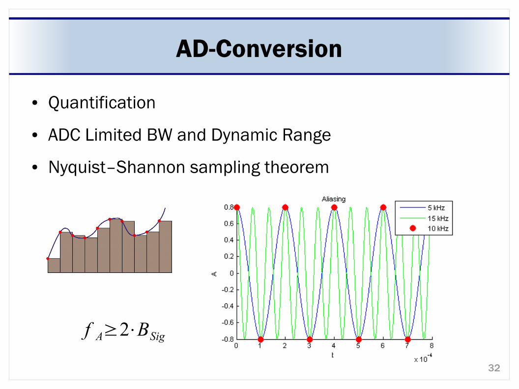
AD-Conversion
● Quantification
● ADC Limited BW and Dynamic Range
● Nyquist–Shannon sampling theorem
f A≥2⋅BSig
33
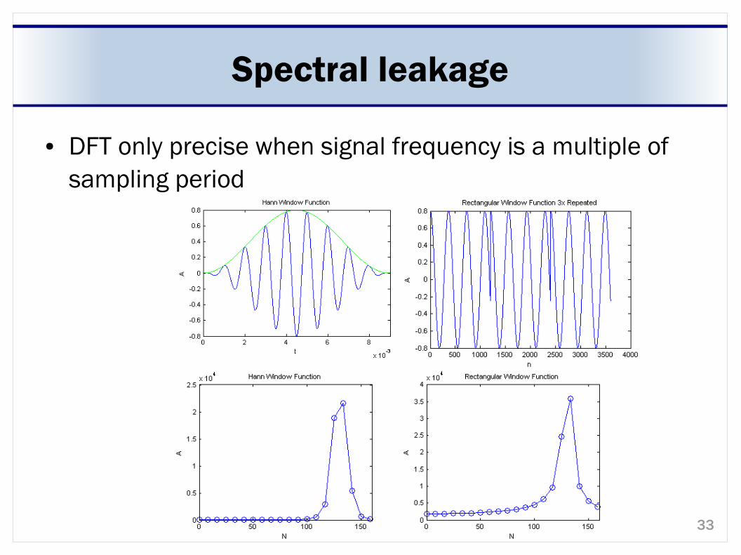
Spectral leakage
● DFT only precise when signal frequency is a multiple of sampling period
34
Sources
● Elektronikkurs 2010, 2. Teil: Rauschen und Störungen
● Motchenbacher, Fitchen: Low-Noise elecronic Design
● Kenneth L. Kaiser: Electromagnetic Compatibility Handbook
● Henry W. Ott: Noise Reduction Techniques in Electronic System
● Blake Peterson, Agilent Spectrum Analysis Basics, Application Note 150
● G. Vasilescu: Electronic Noise and Interfering Signals
● R. Morrison: Grounding and Shielding: Circuits and Interference