Embed Size (px)
Citation preview
Bedienungsanleitung
(Originalanleitung) Operating Instructions
(Translation of original instructions)
Elektronischer
Neigungsgeber
Electronic
Inclinometer
HIT 1500
SAE J1939
Mat –
Nr.
669
997
/ S
tand: 30
.06
.20
17
D /
E
2 HIT 1500 SAE J1939
Stand: 30.06.2017 HYDAC ELECTRONIC GMBH Mat. Nr.: 669997
D
Inhalt
1. Sicherheitshinweis _________________________________________________ 4
2. Haftungsausschluss ________________________________________________ 4
3. Beschreibung ______________________________________________________ 5
4. Allgemeines _______________________________________________________ 5
5. Montage __________________________________________________________ 5
6. Anschlussbelegungen _______________________________________________ 6
7. Protokolldaten J1939 ________________________________________________ 6
8. Technische Daten __________________________________________________ 7
9. Typenschlüssel ____________________________________________________ 8
10. Koordinatensystem und Drehrichtung _________________________________ 9
11. Elektrisches Zubehör ______________________________________________ 10
12. Geräteabmessungen _______________________________________________ 11
HIT 1500 SAE J1939 3
Stand: 30.06.2017 HYDAC ELECTRONIC GMBH Mat. Nr.: 669997
D
Vorwort
Für Sie, den Benutzer unseres Produktes, haben wir in dieser Dokumentation die wichtigsten Hinweise zum Bedienen und Warten zusammengestellt. Sie dient Ihnen dazu, das Produkt kennen zu lernen und seine bestimmungsgemäßen Einsatzmöglichkeiten optimal zu nutzen. Diese Dokumentation muss ständig am Einsatzort verfügbar sein. Bitte beachten Sie, dass die in dieser Dokumentation gemachten Angaben der Gerätetechnik zu dem Zeitpunkt der Literaturerstellung entsprechen. Abweichungen bei technischen Angaben, Abbildungen und Maßen sind deshalb möglich. Entdecken Sie beim Lesen dieser Dokumentation Fehler oder haben weitere Anregungen und Hinweise, so wenden Sie sich bitte an: HYDAC ELECTRONIC GMBH Technische Dokumentation Hauptstraße 27 66128 Saarbrücken -Deutschland- Tel: +49(0)6897 / 509-01 Fax: +49(0)6897 / 509-1726 Email: [email protected] Die Redaktion freut sich über Ihre Mitarbeit. „Aus der Praxis für die Praxis“
4 HIT 1500 SAE J1939
Stand: 30.06.2017 HYDAC ELECTRONIC GMBH Mat. Nr.: 669997
D
1. Sicherheitshinweis Überprüfen Sie vor der Inbetriebnahme den Zustand des Gerätes sowie des mitgelieferten Zubehörs. Lesen Sie vor der Inbetriebnahme des Gerätes die Bedienungsanleitung sowie die SAE J1939 Protokollbeschreibung und stellen Sie sicher, dass das Gerät für Ihre Anwendung geeignet ist. Falsche Handhabung bzw. die Nichteinhaltung von Gebrauchshinweisen oder technischen Angaben kann zu Sach- und / oder Personenschäden führen.
bedeutet, dass Tod, schwere Körperverletzung oder erheblicher Sachschaden eintreten können, wenn die entsprechenden Vorsichtsmaßnahmen nicht getroffen werden.
WARNUNG !
bedeutet, dass eine leichte Körperverletzung oder ein Sachschaden eintreten kann, wenn die entsprechenden Vorsichtsmaßnahmen nicht getroffen werden.
VORSICHT !
bezeichnet wichtige Informationen bzw. Merkmale und Anwendungstipps des verwendeten Produkts.
2. Haftungsausschluss Diese Bedienungsanleitung haben wir nach bestem Wissen und Gewissen erstellt. Es ist dennoch nicht auszuschließen, dass trotz größter Sorgfalt sich Fehler eingeschlichen haben könnten. Haben Sie bitte deshalb Verständnis dafür, dass wir, soweit sich nachstehend nichts anderes ergibt, unsere Gewährleistung und Haftung - gleich aus welchen Rechtsgründen - für die Angaben in dieser Bedienungsanleitung ausschließen. Insbesondere haften wir nicht für entgangenen Gewinn oder sonstige Vermögensschäden. Dieser Haftungsausschluss gilt nicht bei Vorsatz und grober Fahrlässigkeit. Er gilt ferner nicht für Mängel, die arglistig verschwiegen wurden oder deren Abwesenheit garantiert wurde, sowie bei schuldhafter Verletzung von Leben, Körper und Gesundheit. Sofern wir fahrlässig eine vertragswesentliche Pflicht verletzen, ist unsere Haftung auf den vorhersehbaren Schaden begrenzt. Ansprüche aus Produkthaftung bleiben unberührt. Im Falle der Übersetzung ist der Text der deutschen Originalbedienungsanleitung der allein gültige.
HIT 1500 SAE J1939 5
Stand: 30.06.2017 HYDAC ELECTRONIC GMBH Mat. Nr.: 669997
D
3. Beschreibung Die Neigungsgeber der Familie HIT 1500 sind ein- oder zweiachsige digitale Neigungsgeber, die zur Erfassung der Neigung zur Horizontalen eingesetzt werden. Die erfasste Neigung wird digitalisiert und über das SAE J1939-Protokoll dem CAN-Feldbussystem zur Verfügung gestellt. Für den Anwender sind die Geräteparameter mit handelsüblicher CAN-Software einsehbar und konfigurierbar. Die Neigungsgeber verfügen über sehr präzise und robuste Sensorzellen auf MEMS-Basis. Durch herausragende Temperatur- und EMV-Eigenschaften, sowie die kompakte Bauform sind die Geräte in einem breiten Anwendungsfeld im mobilen Bereich einsetzbar.
4. Allgemeines Die Neigungsgeber der Serie HIT 1500 werden einzeln auf rechnergesteuerten Prüfplätzen abgeglichen und einem Endtest unterzogen. Sie sind wartungsfrei und arbeiten beim Einsatz innerhalb der Spezifikationen (siehe Technische Daten) einwandfrei. Falls trotzdem Fehler auftreten, wenden Sie sich bitte an den HYDAC-Service. Fremdeingriffe in das Gerät führen zum Erlöschen jeglicher Gewährleistungsansprüche. Die Protokollbeschreibung finden Sie zum Download auf unserer Homepage unter: →Produkte→Sensorik→Produktsuche http://www.hydac.com/de-de/produkte/sensorik/show/Material/index.html Bei Eingabe der Materialnummer (9xxxxx) erscheint das entsprechende ZIP-file (EDS_9xxxxx_HIT15XX-XXX-X-XXX-X-XX-X-XXX.ZIP), welches die Protokollbeschreibung enthält. Bei Fragen bezüglich der technischen Daten oder Eignung für Ihre Anwendungen, wenden Sie sich bitte an unseren technischen Vertrieb.
5. Montage Der Neigungsgeber wird über seine Flanschplatte direkt an der Arbeitsmaschine montiert. Der Einbauort sollte vorzugsweise so gewählt werden, dass der Einfluss von Vibrationen oder Schlägen möglichst gering ist. Die Einbaulage ergibt sich aus der gewählten Variante gemäß Typenschlüssel (primäre / sekundäre Neigungsachse bzw. „slope long“ / „slope lateral“). Anordnung des Koordinatensystems und Drehrichtung siehe Kap. 10. Der elektrische Anschluss sollte von einem Fachmann nach den jeweiligen Landesvorschriften durchgeführt werden (VDE 0100 in Deutschland). Die Neigungsgeber der Serie HIT 1500 tragen das -Zeichen. Eine Konformitätserklärung ist auf Anfrage erhältlich. Es gelten die EMV-Normen: 61000-6-1, EN 61000-6-2, EN 61000-6-3, EN 61000-6-4. Die Forderungen der Normen werden nur bei ordnungsgemäßer und fachmännischer Erdung des Neigungsgebergehäuses erreicht.
6 HIT 1500 SAE J1939
Stand: 30.06.2017 HYDAC ELECTRONIC GMBH Mat. Nr.: 669997
D
Zusätzliche Montagehinweise, die erfahrungsgemäß den Einfluss elektromagnetischer Störungen reduzieren:
Möglichst kurze Leitungsverbindungen herstellen.
Konfektionierte Leitungen mit ausreichendem Querschnitt verwenden.
Direkte Nähe zu Verbindungsleitungen von Leistungsverbrauchern oder störenden Elektro- oder Elektronikgeräten ist möglichst zu vermeiden.
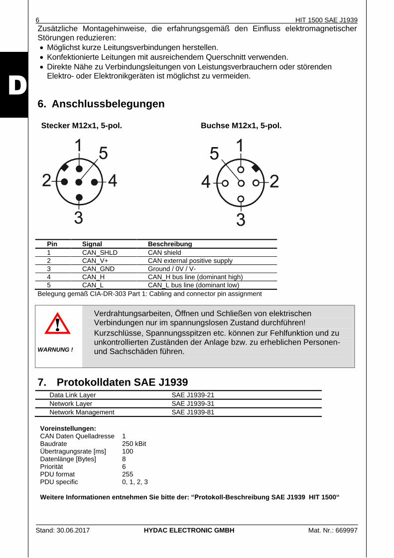
6. Anschlussbelegungen Stecker M12x1, 5-pol.
Buchse M12x1, 5-pol.
Pin Signal Beschreibung
1 CAN_SHLD CAN shield
2 CAN_V+ CAN external positive supply
3 CAN_GND Ground / 0V / V-
4 CAN_H CAN_H bus line (dominant high)
5 CAN_L CAN_L bus line (dominant low)
Belegung gemäß CIA-DR-303 Part 1: Cabling and connector pin assignment
Verdrahtungsarbeiten, Öffnen und Schließen von elektrischen Verbindungen nur im spannungslosen Zustand durchführen!
Kurzschlüsse, Spannungsspitzen etc. können zur Fehlfunktion und zu unkontrollierten Zuständen der Anlage bzw. zu erheblichen Personen- und Sachschäden führen.
WARNUNG !
7. Protokolldaten SAE J1939 Data Link Layer SAE J1939-21
Network Layer SAE J1939-31
Network Management SAE J1939-81
Voreinstellungen: CAN Daten Quelladresse 1 Baudrate 250 kBit Übertragungsrate [ms] 100 Datenlänge [Bytes] 8 Priorität 6 PDU format 255 PDU specific 0, 1, 2, 3 Weitere Informationen entnehmen Sie bitte der: “Protokoll-Beschreibung SAE J1939 HIT 1500“
HIT 1500 SAE J1939 7
Stand: 30.06.2017 HYDAC ELECTRONIC GMBH Mat. Nr.: 669997
D
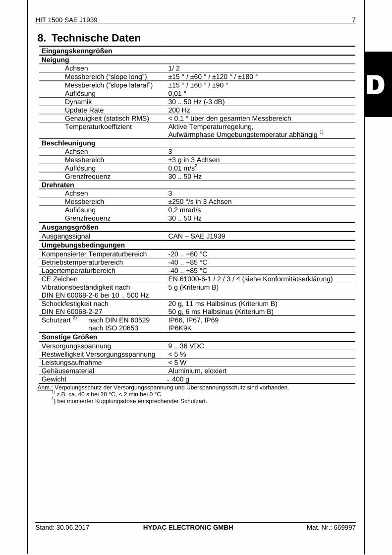
8. Technische Daten Eingangskenngrößen
Neigung
Achsen 1/ 2
Messbereich (“slope long”) ±15 ° / ±60 ° / ±120 ° / ±180 °
Messbereich (“slope lateral”) ±15 ° / ±60 ° / ±90 °
Auflösung 0,01 °
Dynamik 30 .. 50 Hz (-3 dB)
Update Rate 200 Hz
Genauigkeit (statisch RMS) < 0,1 ° über den gesamten Messbereich
Temperaturkoeffizient Aktive Temperaturregelung, Aufwärmphase Umgebungstemperatur abhängig
1)
Beschleunigung
Achsen 3
Messbereich ±3 g in 3 Achsen
Auflösung 0,01 m/s2
Grenzfrequenz 30 .. 50 Hz
Drehraten
Achsen 3
Messbereich ±250 °/s in 3 Achsen
Auflösung 0,2 mrad/s
Grenzfrequenz 30 .. 50 Hz
Ausgangsgrößen
Ausgangssignal CAN – SAE J1939
Umgebungsbedingungen
Kompensierter Temperaturbereich -20 .. +60 °C
Betriebstemperaturbereich -40 .. +85 °C
Lagertemperaturbereich -40 .. +85 °C
CE Zeichen EN 61000-6-1 / 2 / 3 / 4 (siehe Konformitätserklärung)
Vibrationsbeständigkeit nach DIN EN 60068-2-6 bei 10 .. 500 Hz
5 g (Kriterium B)
Schockfestigkeit nach DIN EN 60068-2-27
20 g, 11 ms Halbsinus (Kriterium B) 50 g, 6 ms Halbsinus (Kriterium B)
Schutzart 2)
nach DIN EN 60529 nach ISO 20653
IP66, IP67, IP69 IP6K9K
Sonstige Größen
Versorgungsspannung 9 .. 36 VDC
Restwelligkeit Versorgungsspannung < 5 %
Leistungsaufnahme < 5 W
Gehäusematerial Aluminium, eloxiert
Gewicht 400 g Anm.: Verpolungsschutz der Versorgungsspannung und Überspannungsschutz sind vorhanden.
1) z.B. ca. 40 s bei 20 °C, < 2 min bei 0 °C
2) bei montierter Kupplungsdose entsprechender Schutzart.
8 HIT 1500 SAE J1939
Stand: 30.06.2017 HYDAC ELECTRONIC GMBH Mat. Nr.: 669997
D
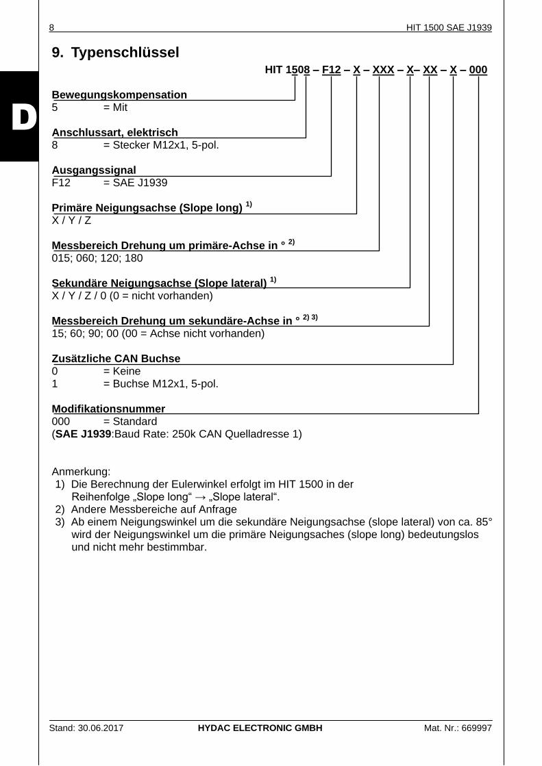
9. Typenschlüssel HIT 1508 – F12 – X – XXX – X– XX – X – 000
Bewegungskompensation 5 = Mit Anschlussart, elektrisch 8 = Stecker M12x1, 5-pol. Ausgangssignal F12 = SAE J1939 Primäre Neigungsachse (Slope long) 1)
X / Y / Z Messbereich Drehung um primäre-Achse in ° 2) 015; 060; 120; 180 Sekundäre Neigungsachse (Slope lateral) 1)
X / Y / Z / 0 (0 = nicht vorhanden) Messbereich Drehung um sekundäre-Achse in ° 2) 3) 15; 60; 90; 00 (00 = Achse nicht vorhanden) Zusätzliche CAN Buchse 0 = Keine 1 = Buchse M12x1, 5-pol. Modifikationsnummer 000 = Standard (SAE J1939:Baud Rate: 250k CAN Quelladresse 1) Anmerkung: 1) Die Berechnung der Eulerwinkel erfolgt im HIT 1500 in der
Reihenfolge „Slope long“ → „Slope lateral“. 2) Andere Messbereiche auf Anfrage 3) Ab einem Neigungswinkel um die sekundäre Neigungsachse (slope lateral) von ca. 85°
wird der Neigungswinkel um die primäre Neigungsaches (slope long) bedeutungslos und nicht mehr bestimmbar.
HIT 1500 SAE J1939 9
Stand: 30.06.2017 HYDAC ELECTRONIC GMBH Mat. Nr.: 669997
D
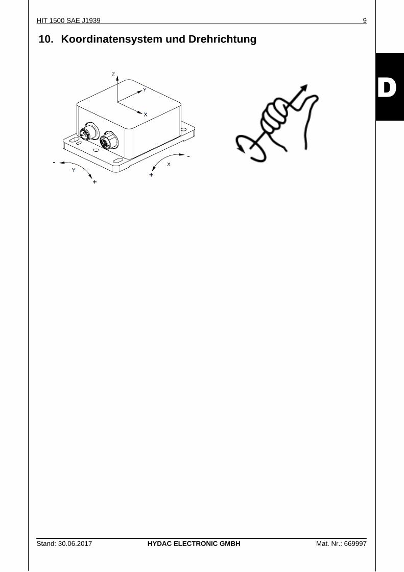
10. Koordinatensystem und Drehrichtung
10 HIT 1500 SAE J1939
Stand: 30.06.2017 HYDAC ELECTRONIC GMBH Mat. Nr.: 669997
D
11. Elektrisches Zubehör
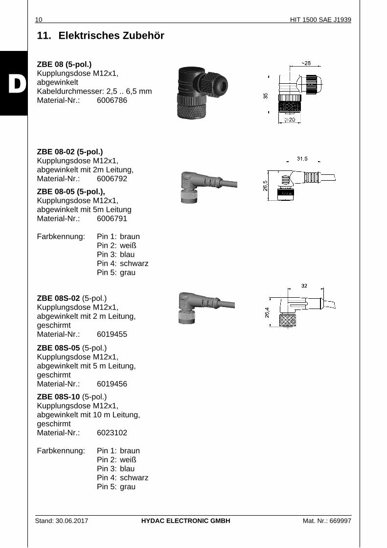
ZBE 08 (5-pol.) Kupplungsdose M12x1, abgewinkelt Kabeldurchmesser: 2,5 .. 6,5 mm Material-Nr.: 6006786
ZBE 08-02 (5-pol.) Kupplungsdose M12x1, abgewinkelt mit 2m Leitung, Material-Nr.: 6006792
ZBE 08-05 (5-pol.), Kupplungsdose M12x1, abgewinkelt mit 5m Leitung Material-Nr.: 6006791
Farbkennung: Pin 1: braun Pin 2: weiß Pin 3: blau Pin 4: schwarz
Pin 5: grau
ZBE 08S-02 (5-pol.) Kupplungsdose M12x1, abgewinkelt mit 2 m Leitung, geschirmt Material-Nr.: 6019455
ZBE 08S-05 (5-pol.) Kupplungsdose M12x1, abgewinkelt mit 5 m Leitung, geschirmt Material-Nr.: 6019456
ZBE 08S-10 (5-pol.) Kupplungsdose M12x1, abgewinkelt mit 10 m Leitung, geschirmt Material-Nr.: 6023102 Farbkennung: Pin 1: braun
Pin 2: weiß Pin 3: blau Pin 4: schwarz Pin 5: grau
HIT 1500 SAE J1939 11
Stand: 30.06.2017 HYDAC ELECTRONIC GMBH Mat. Nr.: 669997
D
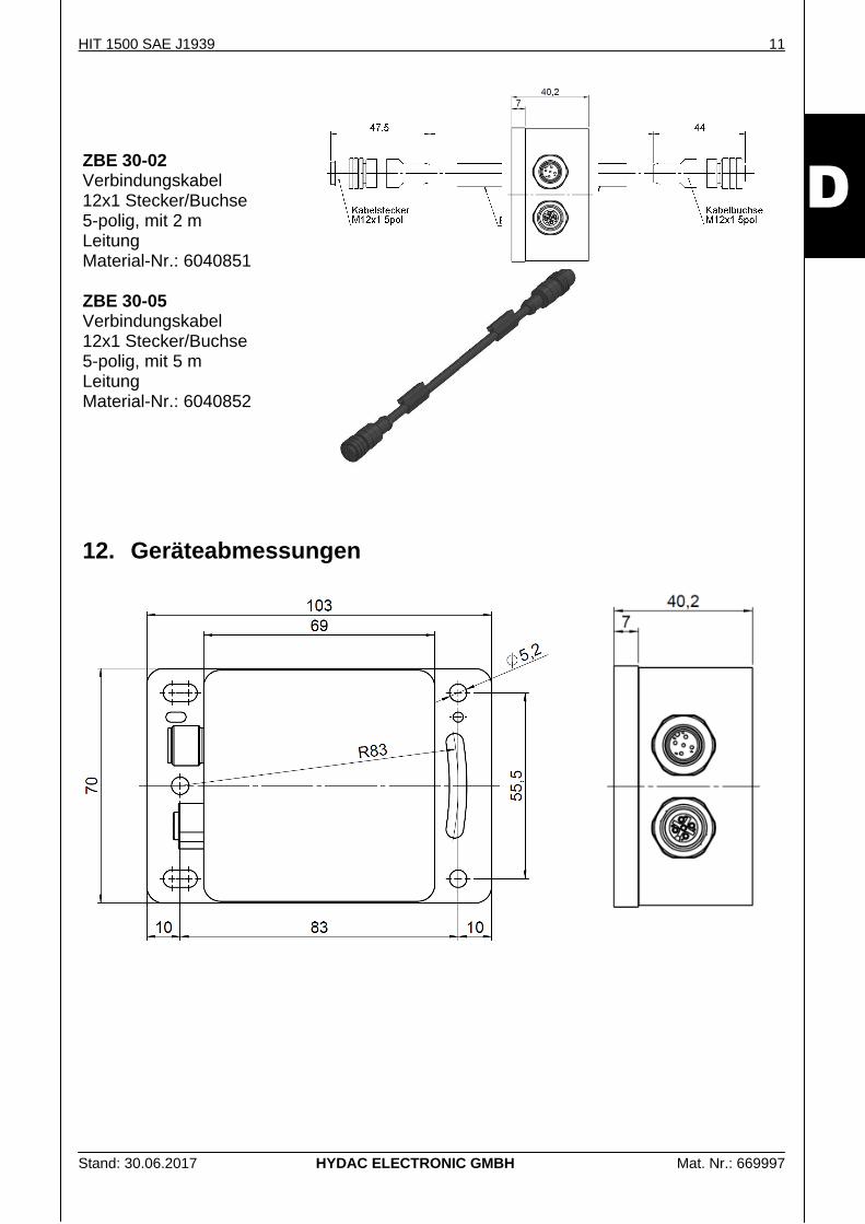
ZBE 30-02 Verbindungskabel 12x1 Stecker/Buchse 5-polig, mit 2 m Leitung Material-Nr.: 6040851 ZBE 30-05 Verbindungskabel 12x1 Stecker/Buchse 5-polig, mit 5 m Leitung Material-Nr.: 6040852
12. Geräteabmessungen
12 HIT 1500 SAE J1939
Stand: 30.06.2017 HYDAC ELECTRONIC GMBH Mat. Nr.: 669997
D
HYDAC ELECTRONIC GMBH Hauptstr. 27 D-66128 Saarbrücken Germany
Web: www.hydac.com E-Mail: [email protected] Tel.: +49 (0)6897 509-01 Fax.: +49 (0)6897 509-1726
HYDAC Service Für Fragen zu Reparaturen steht Ihnen der HYDAC Service zur Verfügung.
HYDAC SERVICE GMBH Hauptstr. 27 D-66128 Saarbrücken Germany Tel.: +49 (0)6897 509-1936 Fax.: +49 (0)6897 509-1933
Anmerkung
Die Angaben in dieser Bedienungsanleitung beziehen sich auf die beschriebenen Betriebsbedingungen und Einsatzfälle. Bei abweichenden Einsatzfällen und/oder Betriebsbedingungen wenden Sie sich bitte an die entsprechende Fachabteilung.
Bei technischen Fragen, Hinweisen oder Störungen nehmen Sie bitte Kontakt mit Ihrer HYDAC-Vertretung auf.
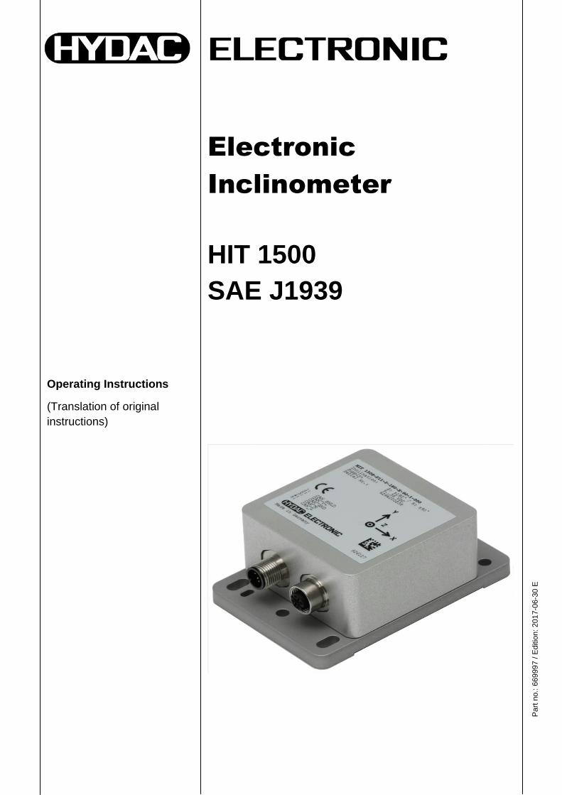
Operating Instructions
(Translation of original
instructions)
Electronic
Inclinometer
HIT 1500
SAE J1939
Part
no.:
669
997 / E
ditio
n: 2017-0
6-3
0 E
2 HIT 1500 SAE J1939
Edition: 2017-06-30 HYDAC ELECTRONIC GMBH Part No.: 669997
E
Contents
1. Safety Information __________________________________________________ 4
2. Disclaimer _________________________________________________________ 4
3. Description ________________________________________________________ 5
4. General ___________________________________________________________ 5
5. Installation ________________________________________________________ 5
6. Pin Connections ____________________________________________________ 6
7. Protocol data for SAE J1939 __________________________________________ 6
8. Technical Data _____________________________________________________ 7
9. Model code ________________________________________________________ 8
10. Coordinate system and turning direction _______________________________ 9
11. Electrical Accessories ______________________________________________ 10
12. Dimensions _______________________________________________________ 11
HIT 1500 SAE J1939 3
Edition: 2017-06-30 HYDAC ELECTRONIC GMBH Part No.: 669997
E
Preface
This manual provides you, as user of our product, with key information on the operation and maintenance of the equipment. It will acquaint you with the product and assist you in obtaining maximum benefit in the applications for which it is designed. Keep the manual in the vicinity of the instrument for immediate reference. Please note: the specifications given in this documentation regarding the instrument technology were correct at the time of publishing. Modifications to technical specifications, illustrations and dimensions are therefore possible. If you discover errors while reading the documentation or have additional suggestions or tips, please contact us at: HYDAC ELECTRONIC GMBH Technical Documentation Hauptstrasse 27 66128 Saarbruecken -Germany- Phone: +49(0)6897 / 509-01 Fax: +49(0)6897 / 509-1726 Email: [email protected] We look forward to receiving your input. "Putting experience into practice"
4 HIT 1500 SAE J1939
Edition: 2017-06-30 HYDAC ELECTRONIC GMBH Part No.: 669997
E
1. Safety Information Before commissioning, check the instrument and any accessories supplied. Before commissioning, please read the operating instructions as well as the SAE J1939 Protocol Description. Ensure that the unit is suitable for your application. If the instrument is not handled correctly, or if the operating instructions and specifications are not adhered to, damage to property or personal injury can result.
means that death, serious injury or major damage to property could occur if the stated precautions are not met.
WARNING !
means that minor injuries or damage to property can occur if the stated precautions are not met.
CAUTION !
indicates important information or features and application suggestions for the product used
2. Disclaimer This operating manual was made to the best of our knowledge Nevertheless and despite the greatest care, it cannot be excluded that mistakes could have crept in. Therefore please understand that in the absence of any provisions to the contrary hereinafter our warranty and liability – for any legal reasons whatsoever – are excluded in respect of the information in this operating manual. In particular, we shall not be liable for lost profit or other financial loss. This exclusion of liability does not apply in cases of intent and gross negligence. Moreover, it does not apply to defects which have been deceitfully concealed or whose absence has been guaranteed, nor in cases of culpable harm to life, physical injury and damage to health. If we negligently breach any material contractual obligation, our liability shall be limited to foreseeable damage. Claims due to the Product Liability shall remain unaffected. In the event of translation, only the original version of the operating manual in German is legally valid.
HIT 1500 SAE J1939 5
Edition: 2017-06-30 HYDAC ELECTRONIC GMBH Part No.: 669997
E
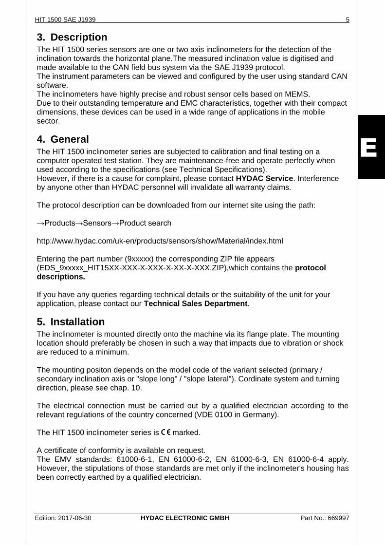
3. Description The HIT 1500 series sensors are one or two axis inclinometers for the detection of the inclination towards the horizontal plane.The measured inclination value is digitised and made available to the CAN field bus system via the SAE J1939 protocol. The instrument parameters can be viewed and configured by the user using standard CAN software. The inclinometers have highly precise and robust sensor cells based on MEMS. Due to their outstanding temperature and EMC characteristics, together with their compact dimensions, these devices can be used in a wide range of applications in the mobile sector.
4. General The HIT 1500 inclinometer series are subjected to calibration and final testing on a computer operated test station. They are maintenance-free and operate perfectly when used according to the specifications (see Technical Specifications). However, if there is a cause for complaint, please contact HYDAC Service. Interference by anyone other than HYDAC personnel will invalidate all warranty claims. The protocol description can be downloaded from our internet site using the path: →Products→Sensors→Product search http://www.hydac.com/uk-en/products/sensors/show/Material/index.html Entering the part number (9xxxxx) the corresponding ZIP file appears (EDS_9xxxxx_HIT15XX-XXX-X-XXX-X-XX-X-XXX.ZIP),which contains the protocol descriptions. If you have any queries regarding technical details or the suitability of the unit for your application, please contact our Technical Sales Department.
5. Installation The inclinometer is mounted directly onto the machine via its flange plate. The mounting location should preferably be chosen in such a way that impacts due to vibration or shock are reduced to a minimum. The mounting positon depends on the model code of the variant selected (primary / secondary inclination axis or "slope long" / "slope lateral"). Cordinate system and turning direction, please see chap. 10. The electrical connection must be carried out by a qualified electrician according to the relevant regulations of the country concerned (VDE 0100 in Germany). The HIT 1500 inclinometer series is marked. A certificate of conformity is available on request. The EMV standards: 61000-6-1, EN 61000-6-2, EN 61000-6-3, EN 61000-6-4 apply. However, the stipulations of those standards are met only if the inclinometer's housing has been correctly earthed by a qualified electrician.
6 HIT 1500 SAE J1939
Edition: 2017-06-30 HYDAC ELECTRONIC GMBH Part No.: 669997
E
Additional installation suggestions which, from experience, reduce the effect of electromagnetic interference:
Make line connections as short as possible.
Only use the prepared cables with a sufficient diameter.
Keep the instrument well away from the electrical supply lines of power equipment, as well as from any electrical or electronic equipment causing interference.
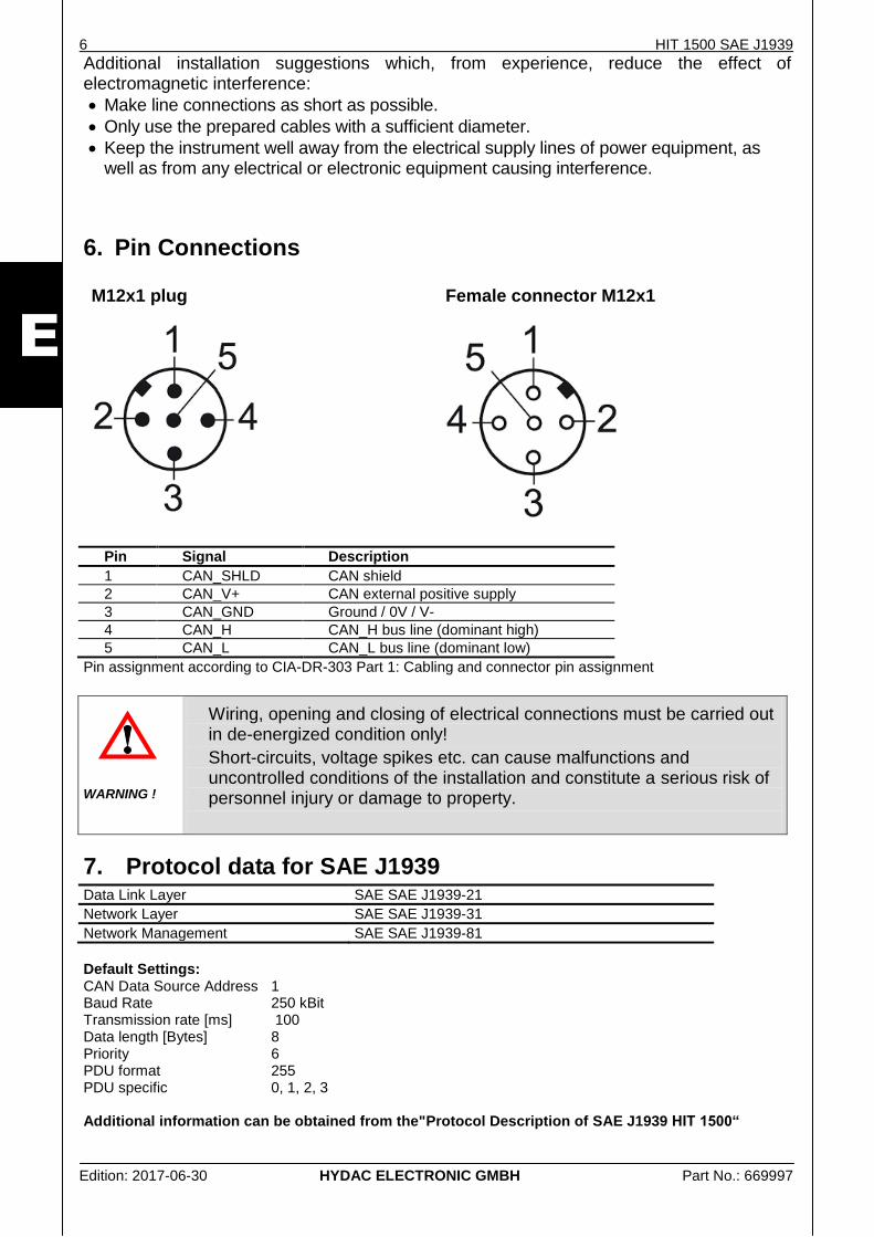
6. Pin Connections M12x1 plug
Female connector M12x1
Pin Signal Description
1 CAN_SHLD CAN shield
2 CAN_V+ CAN external positive supply
3 CAN_GND Ground / 0V / V-
4 CAN_H CAN_H bus line (dominant high)
5 CAN_L CAN_L bus line (dominant low)
Pin assignment according to CIA-DR-303 Part 1: Cabling and connector pin assignment
Wiring, opening and closing of electrical connections must be carried out in de-energized condition only!
Short-circuits, voltage spikes etc. can cause malfunctions and uncontrolled conditions of the installation and constitute a serious risk of personnel injury or damage to property.
WARNING !
7. Protocol data for SAE J1939
Data Link Layer SAE SAE J1939-21
Network Layer SAE SAE J1939-31
Network Management SAE SAE J1939-81
Default Settings: CAN Data Source Address 1 Baud Rate 250 kBit Transmission rate [ms] 100 Data length [Bytes] 8 Priority 6 PDU format 255 PDU specific 0, 1, 2, 3 Additional information can be obtained from the"Protocol Description of SAE J1939 HIT 1500“
HIT 1500 SAE J1939 7
Edition: 2017-06-30 HYDAC ELECTRONIC GMBH Part No.: 669997
E
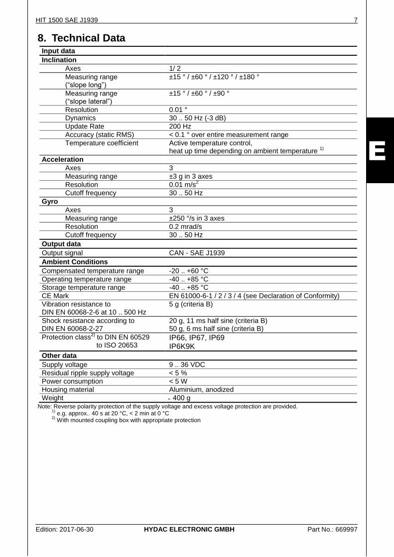
8. Technical Data Input data
Inclination
Axes 1/ 2
Measuring range (“slope long”)
±15 ° / ±60 ° / ±120 ° / ±180 °
Measuring range (“slope lateral”)
±15 ° / ±60 ° / ±90 °
Resolution 0.01 °
Dynamics 30 .. 50 Hz (-3 dB)
Update Rate 200 Hz
Accuracy (static RMS) < 0.1 ° over entire measurement range
Temperature coefficient Active temperature control, heat up time depending on ambient temperature
1)
Acceleration
Axes 3
Measuring range ±3 g in 3 axes
Resolution 0.01 m/s2
Cutoff frequency 30 .. 50 Hz
Gyro
Axes 3
Measuring range ±250 °/s in 3 axes
Resolution 0.2 mrad/s
Cutoff frequency 30 .. 50 Hz
Output data
Output signal CAN - SAE J1939
Ambient Conditions
Compensated temperature range -20 .. +60 °C
Operating temperature range -40 .. +85 °C
Storage temperature range -40 .. +85 °C
CE Mark EN 61000-6-1 / 2 / 3 / 4 (see Declaration of Conformity)
Vibration resistance to DIN EN 60068-2-6 at 10 .. 500 Hz
5 g (criteria B)
Shock resistance according to DIN EN 60068-2-27
20 g, 11 ms half sine (criteria B) 50 g, 6 ms half sine (criteria B)
Protection class2)
to DIN EN 60529 to ISO 20653
IP66, IP67, IP69 IP6K9K
Other data
Supply voltage 9 .. 36 VDC
Residual ripple supply voltage < 5 %
Power consumption < 5 W
Housing material Aluminium, anodized
Weight g Note: Reverse polarity protection of the supply voltage and excess voltage protection are provided.
1) e.g. approx.. 40 s at 20 °C, < 2 min at 0 °C
2) With mounted coupling box with appropriate protection
8 HIT 1500 SAE J1939
Edition: 2017-06-30 HYDAC ELECTRONIC GMBH Part No.: 669997
E
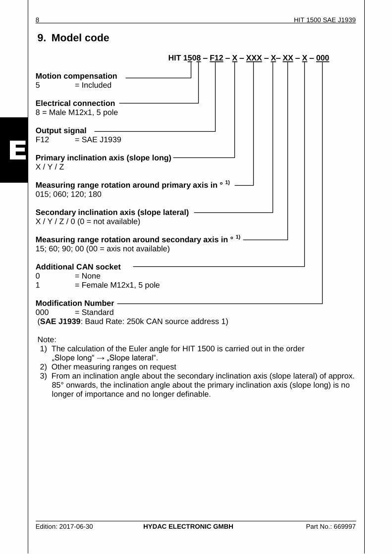
9. Model code
HIT 1508 – F12 – X – XXX – X– XX – X – 000 Motion compensation 5 = Included Electrical connection 8 = Male M12x1, 5 pole Output signal F12 = SAE J1939 Primary inclination axis (slope long)
X / Y / Z Measuring range rotation around primary axis in ° 1) 015; 060; 120; 180 Secondary inclination axis (slope lateral)
X / Y / Z / 0 (0 = not available) Measuring range rotation around secondary axis in ° 1) 15; 60; 90; 00 (00 = axis not available) Additional CAN socket 0 = None 1 = Female M12x1, 5 pole Modification Number 000 = Standard (SAE J1939: Baud Rate: 250k CAN source address 1) Note: 1) The calculation of the Euler angle for HIT 1500 is carried out in the order
„Slope long“ → „Slope lateral“. 2) Other measuring ranges on request 3) From an inclination angle about the secondary inclination axis (slope lateral) of approx.
85° onwards, the inclination angle about the primary inclination axis (slope long) is no longer of importance and no longer definable.
HIT 1500 SAE J1939 9
Edition: 2017-06-30 HYDAC ELECTRONIC GMBH Part No.: 669997
E
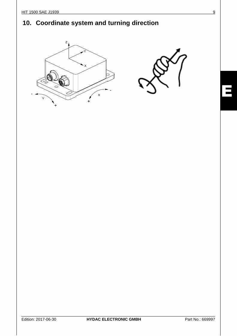
10. Coordinate system and turning direction
10 HIT 1500 SAE J1939
Edition: 2017-06-30 HYDAC ELECTRONIC GMBH Part No.: 669997
E
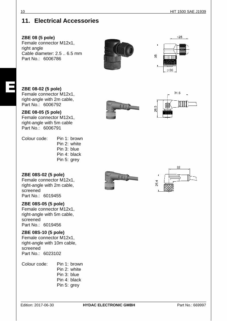
11. Electrical Accessories
ZBE 08 (5 pole) Female connector M12x1, right angle Cable diameter: 2.5 .. 6.5 mm Part No.: 6006786
ZBE 08-02 (5 pole) Female connector M12x1, right-angle with 2m cable, Part No.: 6006792
ZBE 08-05 (5 pole) Female connector M12x1, right-angle with 5m cable Part No.: 6006791
Colour code: Pin 1: brown Pin 2: white Pin 3: blue Pin 4: black
Pin 5: grey
ZBE 08S-02 (5 pole) Female connector M12x1, right-angle with 2m cable, screened Part No.: 6019455
ZBE 08S-05 (5 pole) Female connector M12x1, right-angle with 5m cable, screened Part No.: 6019456
ZBE 08S-10 (5 pole) Female connector M12x1, right-angle with 10m cable, screened Part No.: 6023102 Colour code: Pin 1: brown
Pin 2: white Pin 3: blue Pin 4: black Pin 5: grey
HIT 1500 SAE J1939 11
Edition: 2017-06-30 HYDAC ELECTRONIC GMBH Part No.: 669997
E
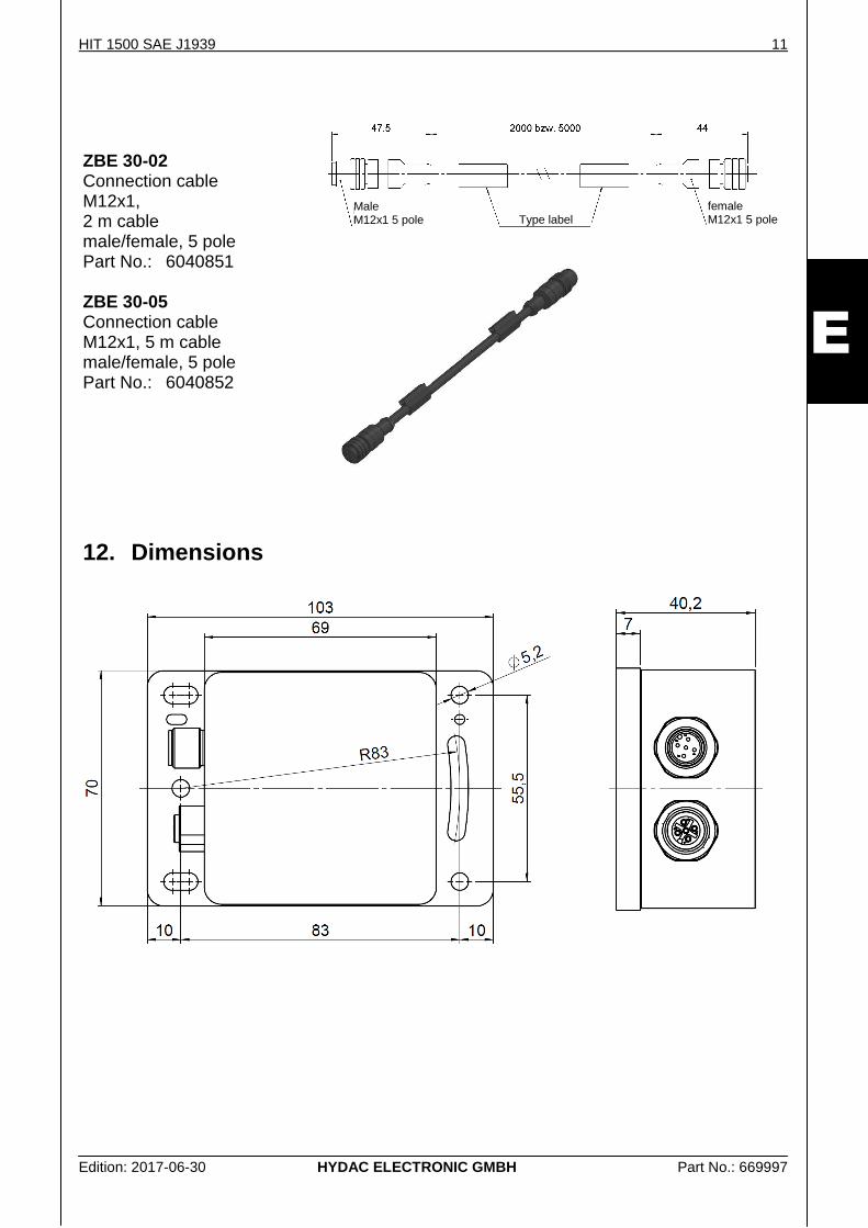
ZBE 30-02 Connection cable M12x1, 2 m cable male/female, 5 pole Part No.: 6040851 ZBE 30-05 Connection cable M12x1, 5 m cable male/female, 5 pole Part No.: 6040852
12. Dimensions
Male M12x1 5 pole Type label
female M12x1 5 pole
12 HIT 1500 SAE J1939
Edition: 2017-06-30 HYDAC ELECTRONIC GMBH Part No.: 669997
E
HYDAC ELECTRONIC GMBH Hauptstr. 27 D-66128 Saarbruecken Germany
Web: www.hydac.com E-Mail: [email protected] Tel.: +49 (0)6897 509-01 Fax: +49 (0)6897 509-1726
HYDAC Service For enquiries regarding repairs, please contact HYDAC Service.
HYDAC SERVICE GMBH Hauptstr. 27 D-66128 Saarbruecken Germany Tel.: +49 (0)6897 509-1936 Fax: +49 (0)6897 509-1933
Note
The information in this manual relates to the operating conditions and applications described. For applications and operating conditions not described, please contact the relevant technical department.
If you have any questions, suggestions, or encounter any problems of a technical nature, please contact your Hydac representative.