Embed Size (px)
Citation preview
© Copperhill Technologies Corp. • https://copperhilltech.com
Serial Control and Communications Vehicle Network
Presented by Wilfried Voss
Copperhill Technologies Corp. Greenfield, MA 01301
https://copperhilltech.com
SAE J1939

Page 2
Literature
Literature on Controller Area Network, CANopen and SAE J1939
https://copperhilltech.com/technical-literature/
© Copperhill Technologies Corp. • https://copperhilltech.com
Page 3
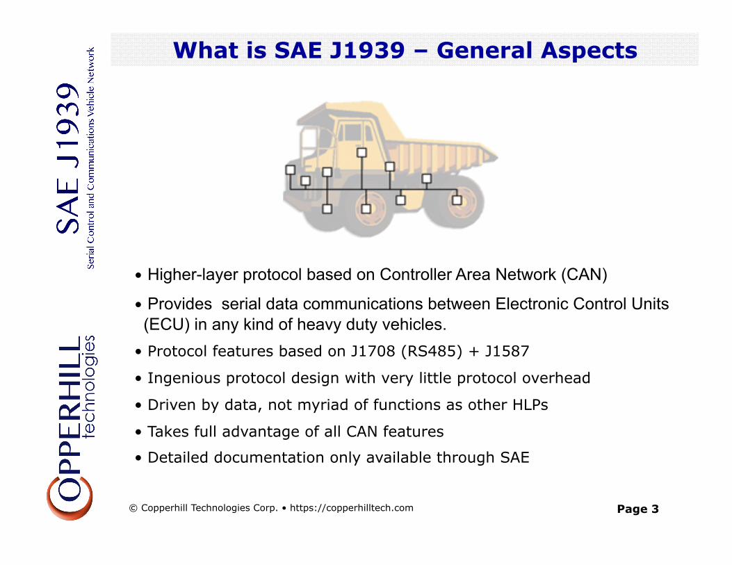
• Higher-layer protocol based on Controller Area Network (CAN)
• Provides serial data communications between Electronic Control Units (ECU) in any kind of heavy duty vehicles. • Protocol features based on J1708 (RS485) + J1587
• Ingenious protocol design with very little protocol overhead
• Driven by data, not myriad of functions as other HLPs
• Takes full advantage of all CAN features
• Detailed documentation only available through SAE
What is SAE J1939 – General Aspects
What is SAE J1939 – General Aspects
© Copperhill Technologies Corp. • https://copperhilltech.com
Page 4
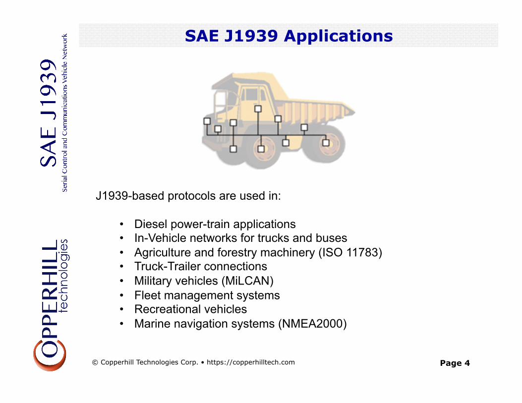
J1939-based protocols are used in:
• Diesel power-train applications • In-Vehicle networks for trucks and buses • Agriculture and forestry machinery (ISO 11783) • Truck-Trailer connections • Military vehicles (MiLCAN) • Fleet management systems • Recreational vehicles • Marine navigation systems (NMEA2000)
SAE J1939 Applications
SAE J1939 Applications
© Copperhill Technologies Corp. • https://copperhilltech.com
Page 5
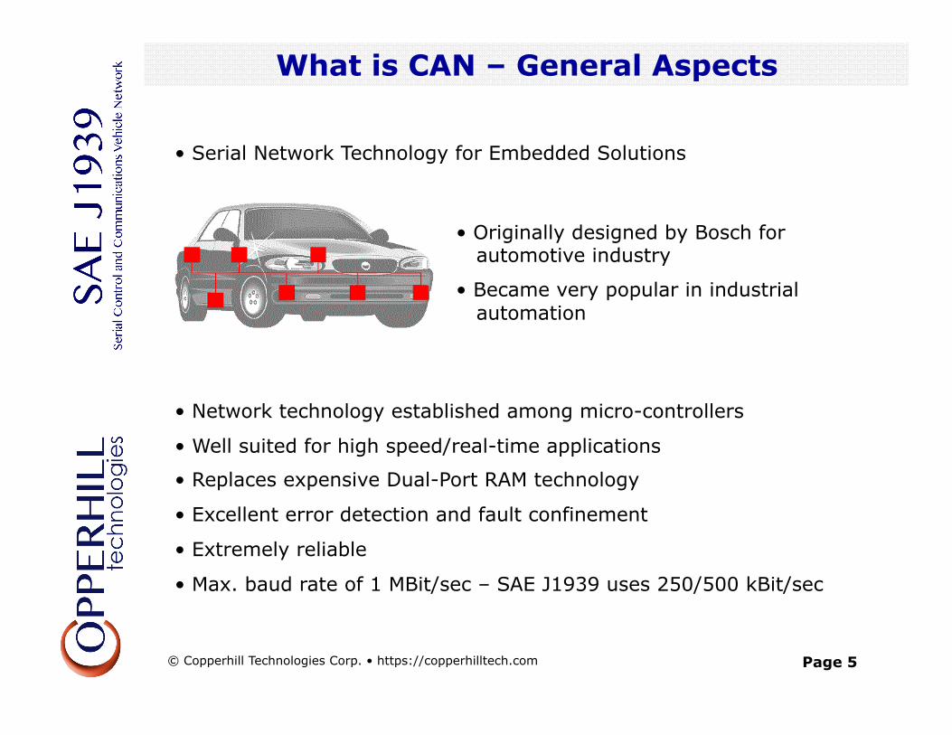
• Originally designed by Bosch for automotive industry
• Became very popular in industrial automation
• Network technology established among micro-controllers
• Well suited for high speed/real-time applications
• Replaces expensive Dual-Port RAM technology
• Excellent error detection and fault confinement
• Extremely reliable
• Max. baud rate of 1 MBit/sec – SAE J1939 uses 250/500 kBit/sec
• Serial Network Technology for Embedded Solutions
What is CAN – General Aspects
What is CAN – General Aspects
© Copperhill Technologies Corp. • https://copperhilltech.com
Page 6
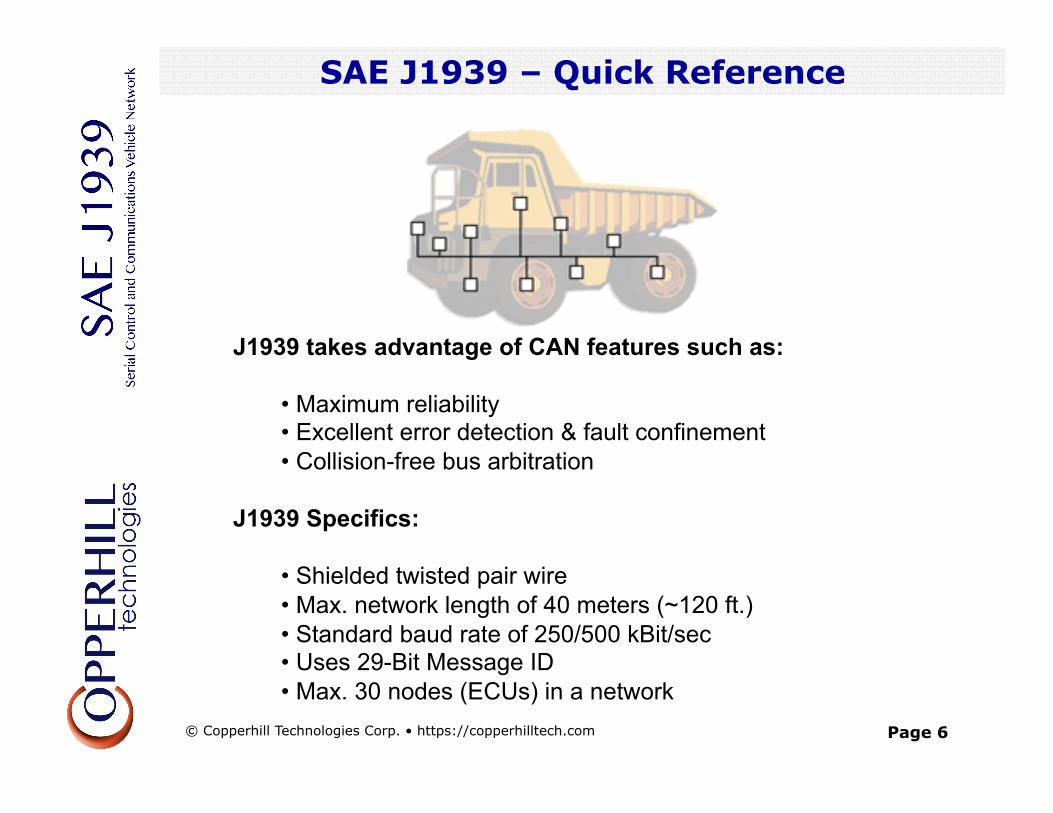
J1939 takes advantage of CAN features such as:
• Maximum reliability • Excellent error detection & fault confinement • Collision-free bus arbitration
J1939 Specifics:
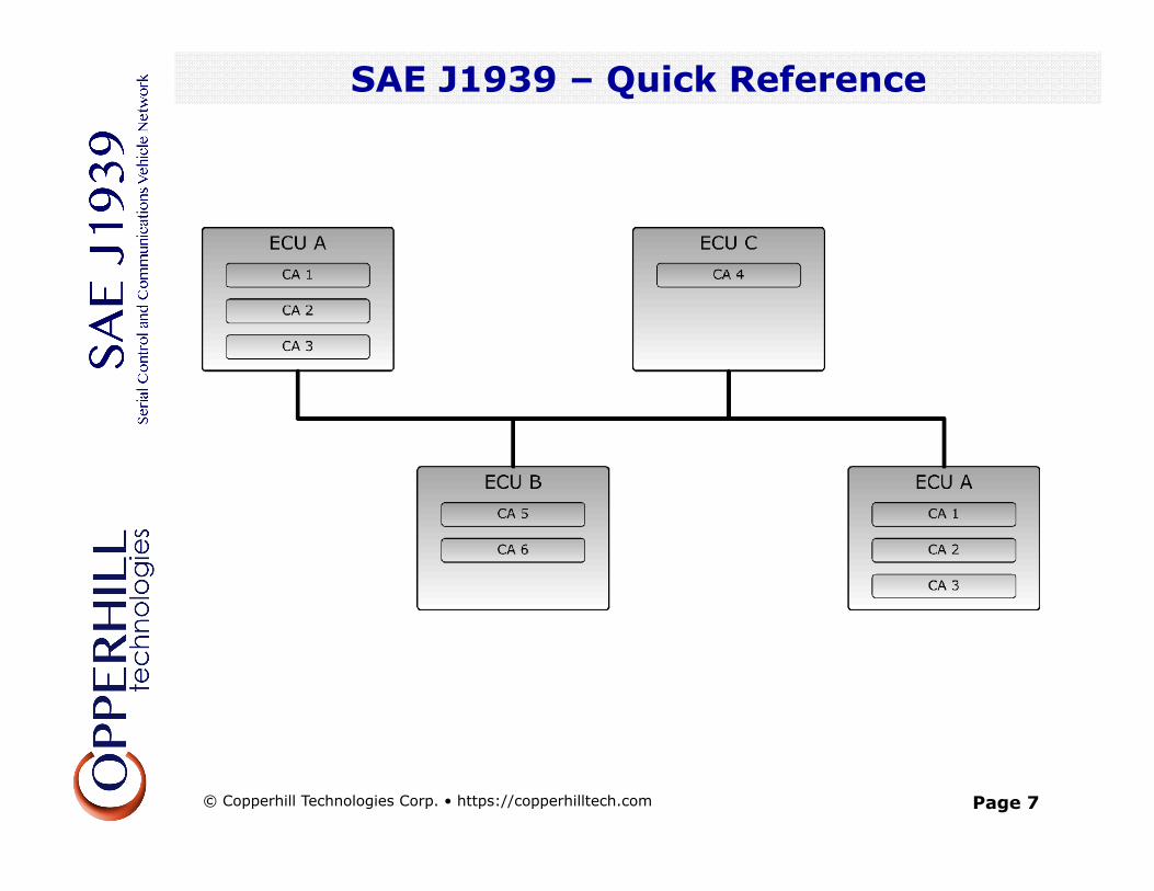
• Shielded twisted pair wire • Max. network length of 40 meters (~120 ft.) • Standard baud rate of 250/500 kBit/sec • Uses 29-Bit Message ID • Max. 30 nodes (ECUs) in a network
SAE J1939 – Quick Reference
SAE J1939 Quick Reference
© Copperhill Technologies Corp. • https://copperhilltech.com
Page 7
SAE J1939 – Quick Reference
SAE J1939 Quick Reference
© Copperhill Technologies Corp. • https://copperhilltech.com
Page 8
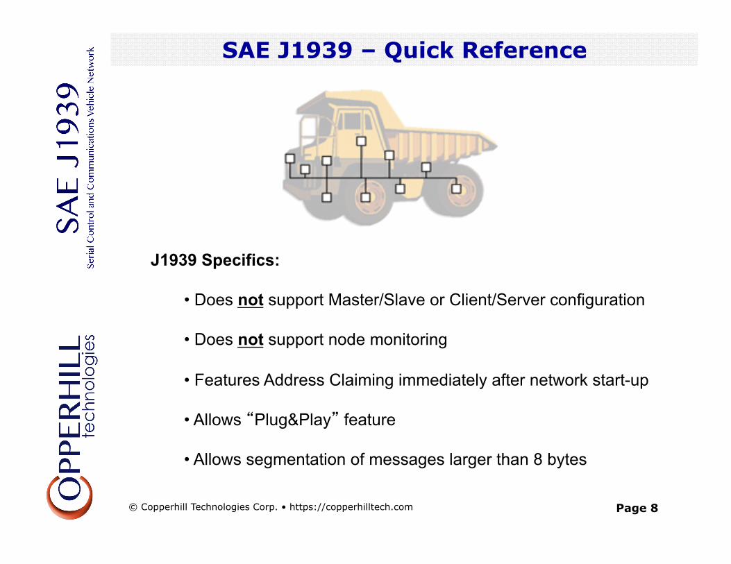
J1939 Specifics:
• Does not support Master/Slave or Client/Server configuration • Does not support node monitoring • Features Address Claiming immediately after network start-up • Allows “Plug&Play” feature • Allows segmentation of messages larger than 8 bytes
SAE J1939 – Quick Reference
SAE J1939 Quick Reference
© Copperhill Technologies Corp. • https://copperhilltech.com
Page 9
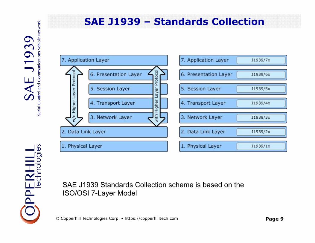
SAE J1939 – Standards Collection
SAE J1939 Standards Collection scheme is based on the ISO/OSI 7-Layer Model
SAE J1939 Standards Collection
© Copperhill Technologies Corp. • https://copperhilltech.com
Page 10
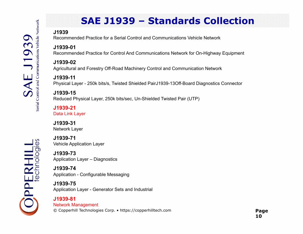
SAE J1939 – Standards Collection J1939 Recommended Practice for a Serial Control and Communications Vehicle Network
J1939-01 Recommended Practice for Control And Communications Network for On-Highway Equipment
J1939-02 Agricultural and Forestry Off-Road Machinery Control and Communication Network
J1939-11 Physical Layer - 250k bits/s, Twisted Shielded PairJ1939-13Off-Board Diagnostics Connector
J1939-15 Reduced Physical Layer, 250k bits/sec, Un-Shielded Twisted Pair (UTP)
J1939-21 Data Link Layer
J1939-31 Network Layer
J1939-71 Vehicle Application Layer
J1939-73 Application Layer – Diagnostics
J1939-74 Application - Configurable Messaging
J1939-75 Application Layer - Generator Sets and Industrial
J1939-81 Network Management
SAE J1939 Standards Collection
© Copperhill Technologies Corp. • https://copperhilltech.com
Page 11
SAE J1939 – Message Format (J1939/21)
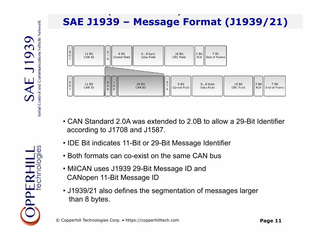
• CAN Standard 2.0A was extended to 2.0B to allow a 29-Bit Identifier according to J1708 and J1587.
• IDE Bit indicates 11-Bit or 29-Bit Message Identifier
• Both formats can co-exist on the same CAN bus
• MilCAN uses J1939 29-Bit Message ID and CANopen 11-Bit Message ID
• J1939/21 also defines the segmentation of messages larger than 8 bytes.
SAE J1939 – Message Format (J1939/21)
© Copperhill Technologies Corp. • https://copperhilltech.com
Page 12
SAE J1939 – Message Format
SAE J1939 – Parameter Group Number
© Copperhill Technologies Corp. • https://copperhilltech.com
Page 13
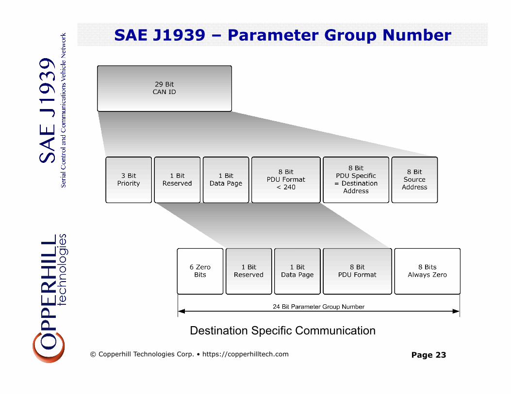
SAE J1939 – Parameter Group Number
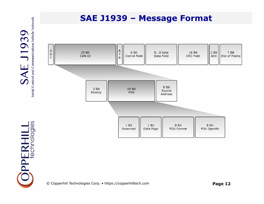
• Parameters embedded in the 29-Bit message identifier are divided into three sections:
• Priority
• PGN (Parameter Group Number)
• 8 Bit Source Address
• PGN identifies the Parameter Group (PG)
• PGs point to information of parameter assignments within 8 byte CAN data field, repetition rate and priority
• 8672 different Parameter Groups per page – 2 pages are available
SAE J1939 – Parameter Group Number
© Copperhill Technologies Corp. • https://copperhilltech.com
Page 14
SAE J1939 – Parameter Group Number
Priority
• First three bits represent priority during arbitration process • Provides eight priority levels • A value of 0 (000) = highest priority; a value of 8 (111) = lowest priority • High priority messages assigned to time critical data such as torque control data from transmission to engine • Lower level priorities suitable for non-time-critical data such as engine configuration data
R
• Reserved for future purposes • Should always be set to 0 when transmitting messages
SAE J1939 – Parameter Group Number
© Copperhill Technologies Corp. • https://copperhilltech.com
Page 15
SAE J1939 – Parameter Group Number
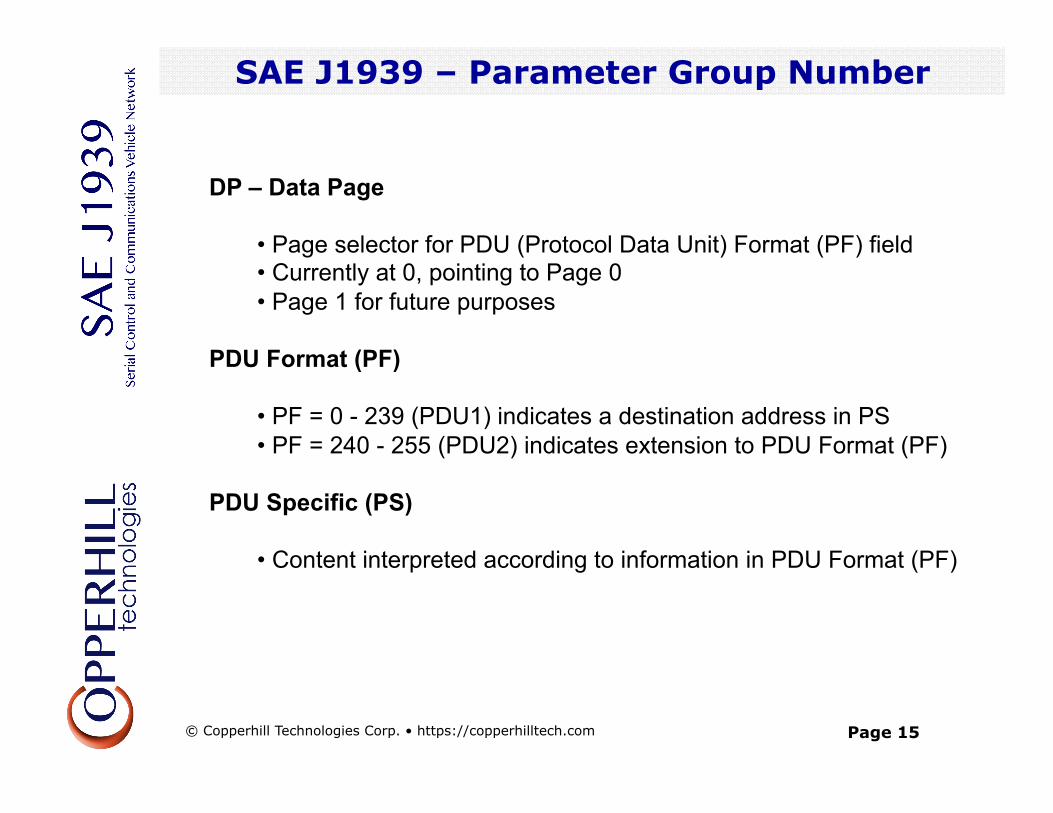
DP – Data Page
• Page selector for PDU (Protocol Data Unit) Format (PF) field • Currently at 0, pointing to Page 0 • Page 1 for future purposes
PDU Format (PF)
• PF = 0 - 239 (PDU1) indicates a destination address in PS • PF = 240 - 255 (PDU2) indicates extension to PDU Format (PF)
PDU Specific (PS)
• Content interpreted according to information in PDU Format (PF)
SAE J1939 - Parameter Group Number
© Copperhill Technologies Corp. • https://copperhilltech.com
Page 16
SAE J1939 – PGNs and SPNs
SAE J1939 – PGNs and SPNs
© Copperhill Technologies Corp. • https://copperhilltech.com
Page 17
SAE J1939 – PGNs and SPNs
SAE J1939 – PGNs and SPNs
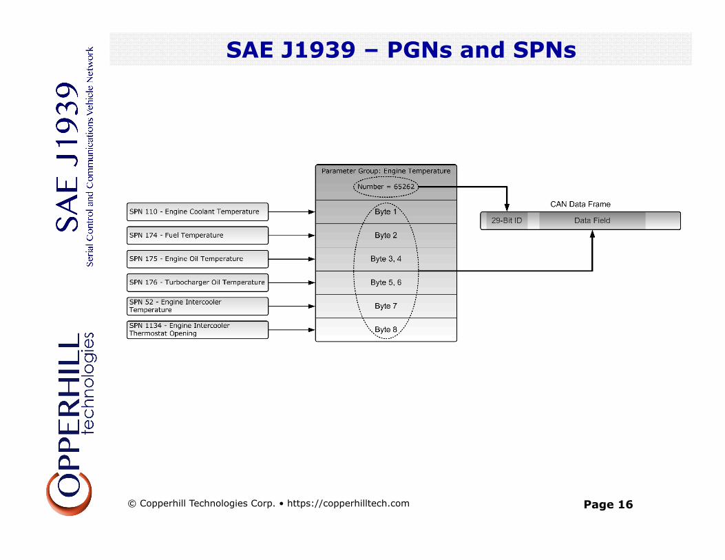
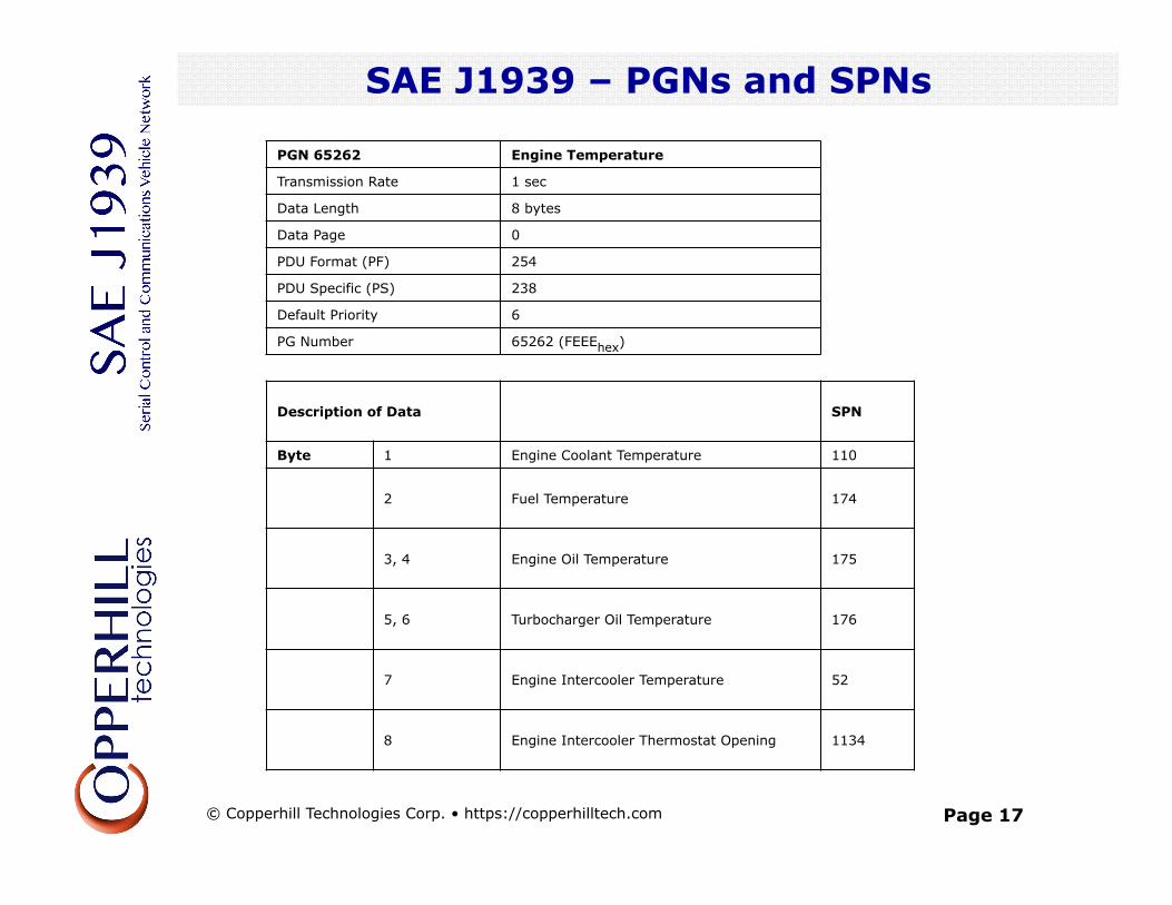
PGN 65262 Engine Temperature Transmission Rate 1 sec Data Length 8 bytes Data Page 0 PDU Format (PF) 254 PDU Specific (PS) 238 Default Priority 6 PG Number 65262 (FEEEhex)
Description of Data SPN Byte 1 Engine Coolant Temperature 110
2 Fuel Temperature 174
3, 4 Engine Oil Temperature 175
5, 6 Turbocharger Oil Temperature 176
7 Engine Intercooler Temperature 52
8 Engine Intercooler Thermostat Opening 1134
© Copperhill Technologies Corp. • https://copperhilltech.com
Page 18
SAE J1939 – PGNs and SPNs
SAE J1939 – PGNs and SPNs
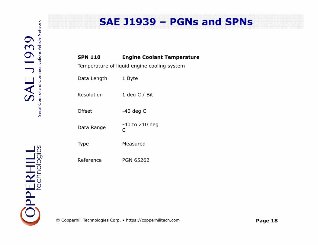
SPN 110 Engine Coolant Temperature
Temperature of liquid engine cooling system
Data Length 1 Byte
Resolution 1 deg C / Bit
Offset -40 deg C
Data Range -40 to 210 deg C
Type Measured
Reference PGN 65262
© Copperhill Technologies Corp. • https://copperhilltech.com
Page 19
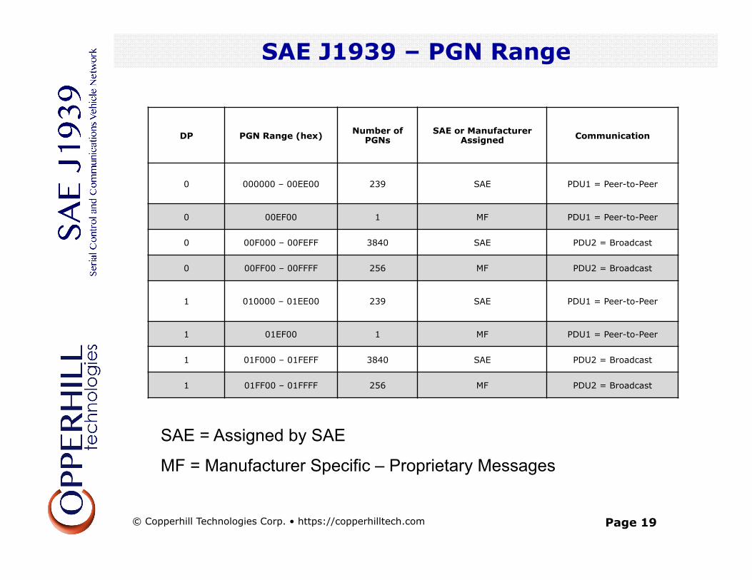
SAE J1939 – PGN Range
SAE J1939 – PGNs and SPNs
DP PGN Range (hex) Number of PGNs SAE or Manufacturer
Assigned Communication
0 000000 – 00EE00 239 SAE PDU1 = Peer-to-Peer
0 00EF00 1 MF PDU1 = Peer-to-Peer 0 00F000 – 00FEFF 3840 SAE PDU2 = Broadcast 0 00FF00 – 00FFFF 256 MF PDU2 = Broadcast
1 010000 – 01EE00 239 SAE PDU1 = Peer-to-Peer
1 01EF00 1 MF PDU1 = Peer-to-Peer 1 01F000 – 01FEFF 3840 SAE PDU2 = Broadcast 1 01FF00 – 01FFFF 256 MF PDU2 = Broadcast
SAE = Assigned by SAE
MF = Manufacturer Specific – Proprietary Messages
© Copperhill Technologies Corp. • https://copperhilltech.com
Page 20
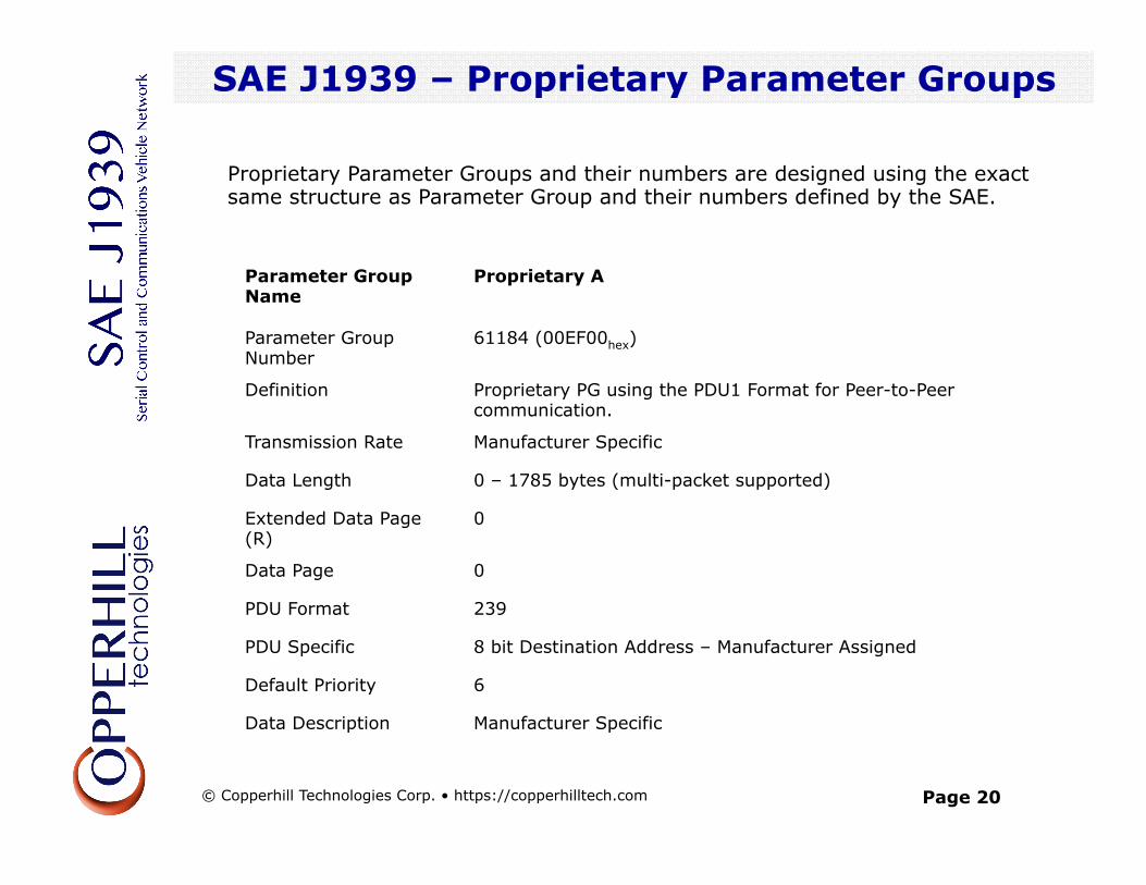
SAE J1939 – Proprietary Parameter Groups
SAE J1939 – Communication Methods
Proprietary Parameter Groups and their numbers are designed using the exact same structure as Parameter Group and their numbers defined by the SAE.
Parameter Group Name
Proprietary A
Parameter Group Number
61184 (00EF00hex)
Definition Proprietary PG using the PDU1 Format for Peer-to-Peer communication.
Transmission Rate Manufacturer Specific
Data Length 0 – 1785 bytes (multi-packet supported)
Extended Data Page (R)
0
Data Page 0
PDU Format 239
PDU Specific 8 bit Destination Address – Manufacturer Assigned
Default Priority 6
Data Description Manufacturer Specific
© Copperhill Technologies Corp. • https://copperhilltech.com
Page 21
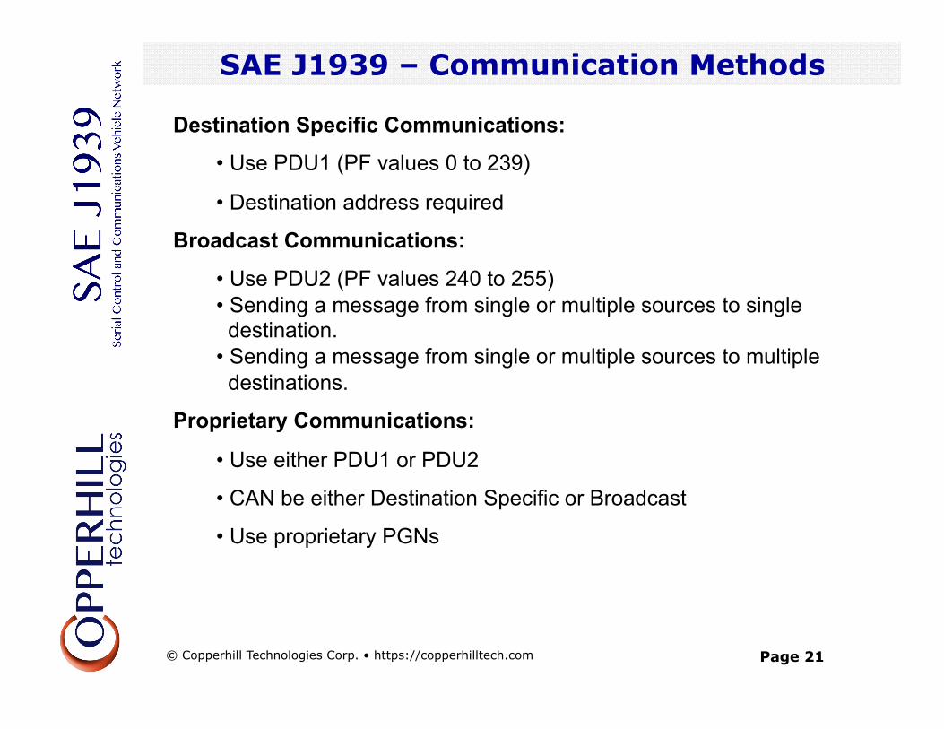
SAE J1939 – Communication Methods
Destination Specific Communications:
• Use PDU1 (PF values 0 to 239)
• Destination address required
Broadcast Communications:
• Use PDU2 (PF values 240 to 255) • Sending a message from single or multiple sources to single destination. • Sending a message from single or multiple sources to multiple destinations.
Proprietary Communications:
• Use either PDU1 or PDU2
• CAN be either Destination Specific or Broadcast
• Use proprietary PGNs
SAE J1939 – Communication Methods
© Copperhill Technologies Corp. • https://copperhilltech.com
Page 22
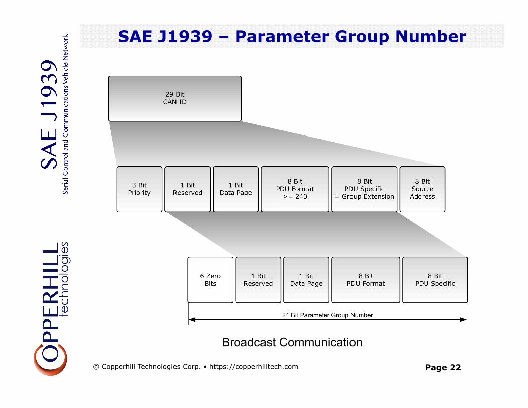
SAE J1939 – Parameter Group Number
SAE J1939 – Parameter Group Number
Broadcast Communication
© Copperhill Technologies Corp. • https://copperhilltech.com
Page 23
SAE J1939 – Parameter Group Number
SAE J1939 – Parameter Group Number
Destination Specific Communication
© Copperhill Technologies Corp. • https://copperhilltech.com
Page 24
SAE J1939 – Source Address
• Source Address = Last 8 bits of 29-Bit message identifier
• Source address = Adress of transmitting ECU (node)
• A total of 254 addresses available
• Every address must be unique within the network
• ECUs cannot share addresses
• PGNs are independent of source address
• Every ECU is allowed to transmit any message
Note: The CAN standard in itself does not support node (ECU) addresses, only message IDs.
SAE J1939 – Source Address
© Copperhill Technologies Corp. • https://copperhilltech.com
Page 25
SAE J1939 – Message Types
SAE J1939 – Network Management
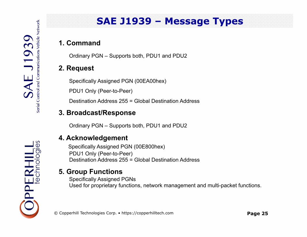
1. Command
Ordinary PGN – Supports both, PDU1 and PDU2
2. Request
Specifically Assigned PGN (00EA00hex)
PDU1 Only (Peer-to-Peer)
Destination Address 255 = Global Destination Address
3. Broadcast/Response
Ordinary PGN – Supports both, PDU1 and PDU2
4. Acknowledgement Specifically Assigned PGN (00E800hex) PDU1 Only (Peer-to-Peer) Destination Address 255 = Global Destination Address
5. Group Functions Specifically Assigned PGNs Used for proprietary functions, network management and multi-packet functions.
© Copperhill Technologies Corp. • https://copperhilltech.com
Page 26
SAE J1939 – Request Message
SAE J1939 – Network Management
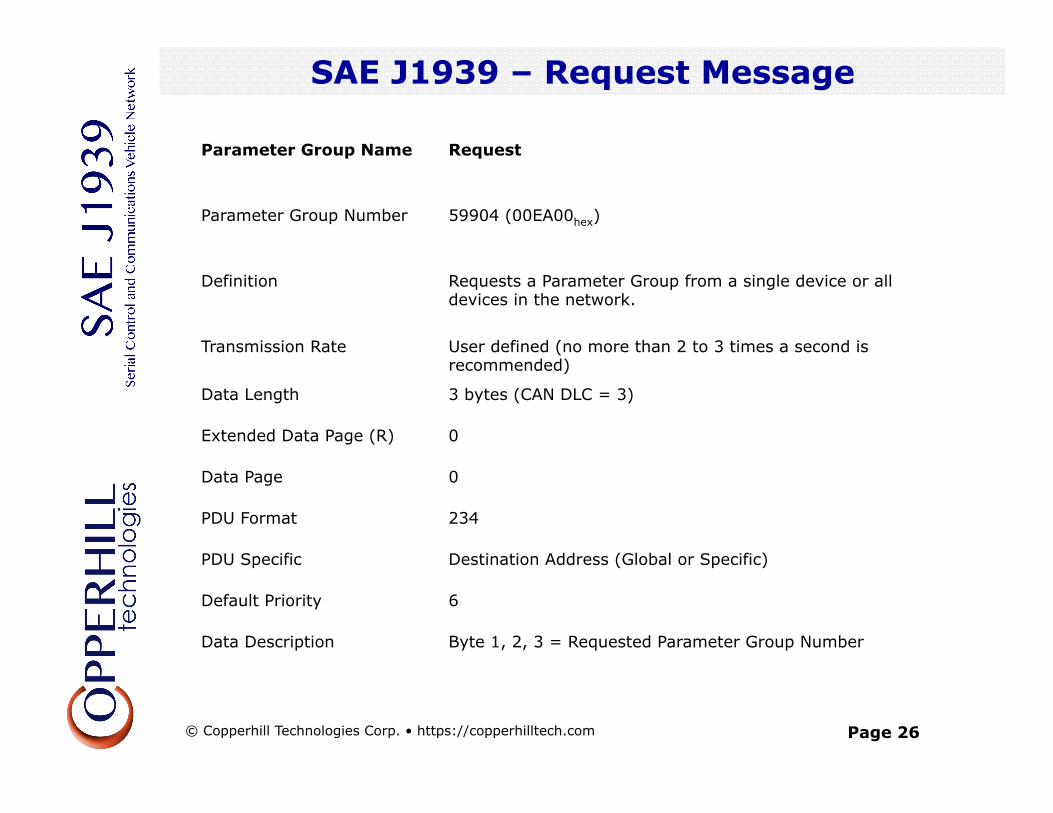
Parameter Group Name Request
Parameter Group Number 59904 (00EA00hex)
Definition Requests a Parameter Group from a single device or all devices in the network.
Transmission Rate User defined (no more than 2 to 3 times a second is recommended)
Data Length 3 bytes (CAN DLC = 3)
Extended Data Page (R) 0
Data Page 0
PDU Format 234
PDU Specific Destination Address (Global or Specific)
Default Priority 6
Data Description Byte 1, 2, 3 = Requested Parameter Group Number
© Copperhill Technologies Corp. • https://copperhilltech.com
Page 27
SAE J1939 – Acknowledgement Message
SAE J1939 – Network Management
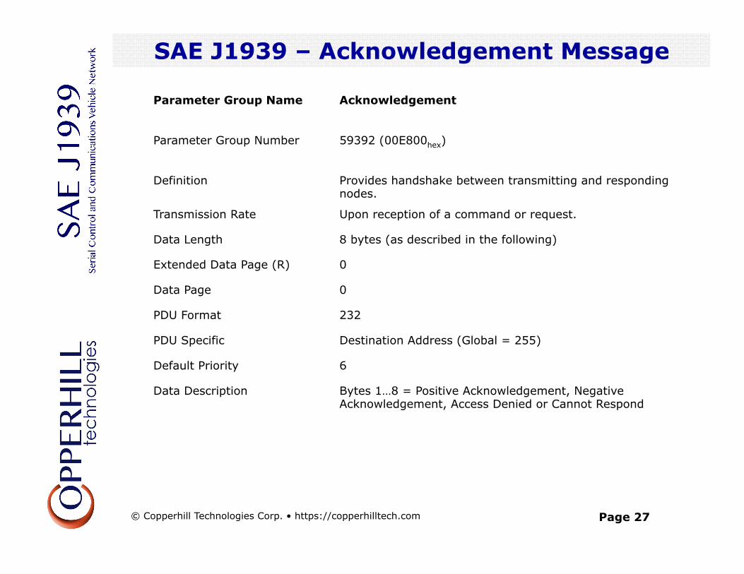
Parameter Group Name Acknowledgement
Parameter Group Number 59392 (00E800hex)
Definition Provides handshake between transmitting and responding nodes.
Transmission Rate Upon reception of a command or request.
Data Length 8 bytes (as described in the following)
Extended Data Page (R) 0
Data Page 0
PDU Format 232
PDU Specific Destination Address (Global = 255)
Default Priority 6
Data Description Bytes 1…8 = Positive Acknowledgement, Negative Acknowledgement, Access Denied or Cannot Respond
© Copperhill Technologies Corp. • https://copperhilltech.com
Page 28
SAE J1939 – Multi-Packet Transport
SAE J1939 – Network Management
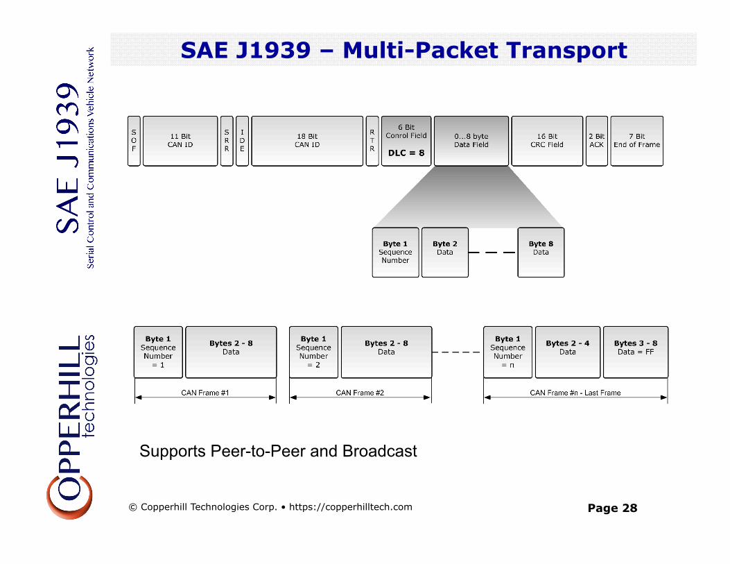
Supports Peer-to-Peer and Broadcast
© Copperhill Technologies Corp. • https://copperhilltech.com
Page 29
SAE J1939 – Broadcast Announce Message
SAE J1939 – Network Management
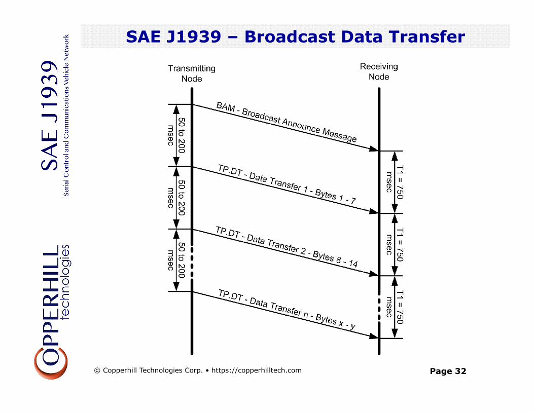
BAM! In order to broadcast a multi-packet message a node must first send a Broadcast Announce Message (BAM). A BAM message contains the following components:
• Parameter Group Number of the multi-packet message • Size of the multi-packet message • Number of packages
The Broadcast Announce Message (BAM) is embedded in the Transport Protocol – Connection Management (TP.CM) PGN 60416 and the actual data transfer is handled by using the Data Transfer PGN 60160.
© Copperhill Technologies Corp. • https://copperhilltech.com
Page 30
SAE J1939 – Transport Protocol
SAE J1939 – Network Management
Parameter Group Name
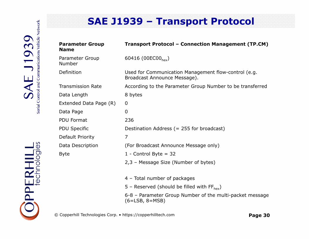
Transport Protocol – Connection Management (TP.CM)
Parameter Group Number
60416 (00EC00hex)
Definition Used for Communication Management flow-control (e.g. Broadcast Announce Message).
Transmission Rate According to the Parameter Group Number to be transferred
Data Length 8 bytes
Extended Data Page (R) 0
Data Page 0
PDU Format 236
PDU Specific Destination Address (= 255 for broadcast)
Default Priority 7
Data Description (For Broadcast Announce Message only)
Byte 1 - Control Byte = 32
2,3 – Message Size (Number of bytes)
4 – Total number of packages
5 – Reserved (should be filled with FFhex)
6-8 – Parameter Group Number of the multi-packet message (6=LSB, 8=MSB)
© Copperhill Technologies Corp. • https://copperhilltech.com
Page 31
SAE J1939 – Transport Protocol
SAE J1939 – Network Management
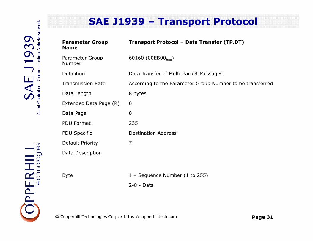
Parameter Group Name
Transport Protocol – Data Transfer (TP.DT)
Parameter Group Number
60160 (00EB00hex)
Definition Data Transfer of Multi-Packet Messages
Transmission Rate According to the Parameter Group Number to be transferred
Data Length 8 bytes
Extended Data Page (R) 0
Data Page 0
PDU Format 235
PDU Specific Destination Address
Default Priority 7
Data Description
Byte 1 – Sequence Number (1 to 255)
2-8 - Data
© Copperhill Technologies Corp. • https://copperhilltech.com
Page 32
SAE J1939 – Broadcast Data Transfer
SAE J1939 – Network Management
© Copperhill Technologies Corp. • https://copperhilltech.com
Page 33
SAE J1939 – Flow Control
SAE J1939 – Network Management
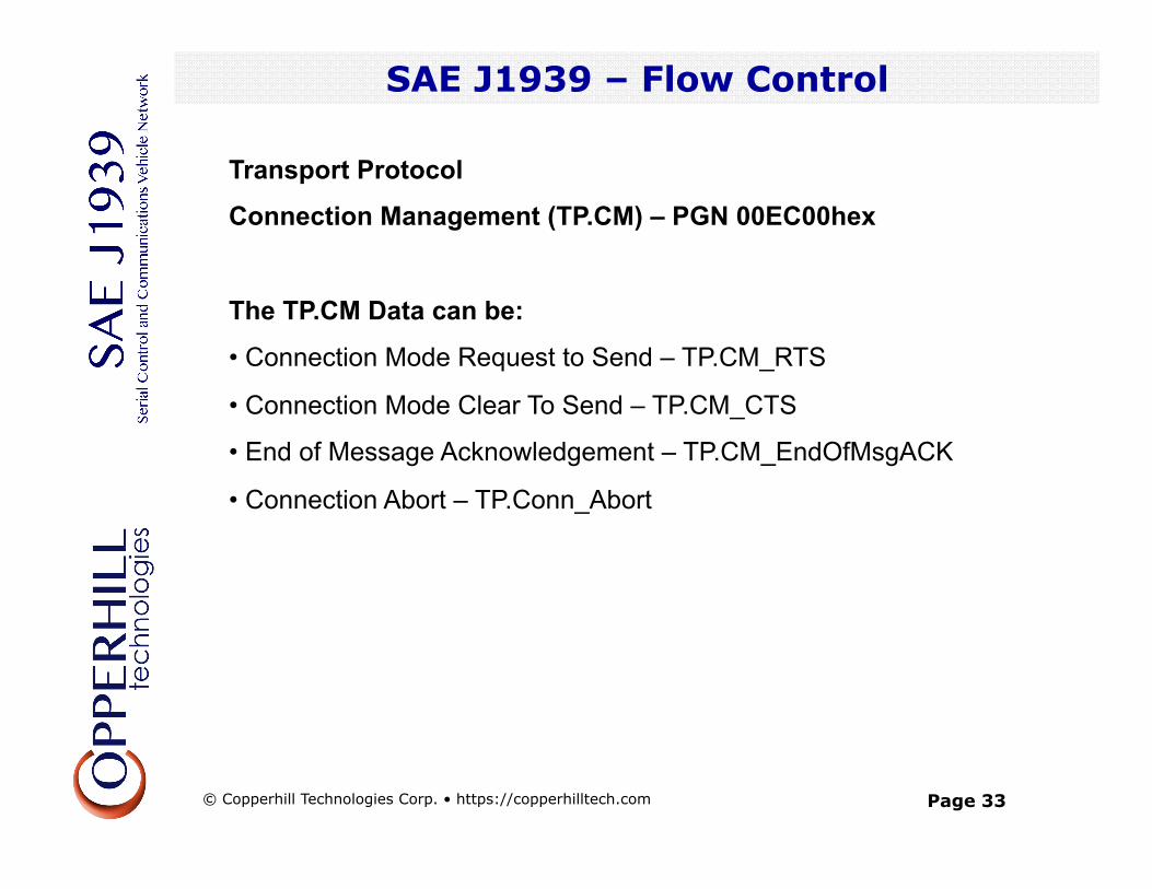
Transport Protocol
Connection Management (TP.CM) – PGN 00EC00hex
The TP.CM Data can be:
• Connection Mode Request to Send – TP.CM_RTS
• Connection Mode Clear To Send – TP.CM_CTS
• End of Message Acknowledgement – TP.CM_EndOfMsgACK
• Connection Abort – TP.Conn_Abort
© Copperhill Technologies Corp. • https://copperhilltech.com
Page 34
SAE J1939 – Network Management
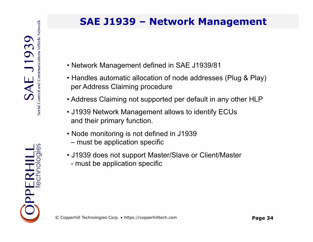
• Network Management defined in SAE J1939/81
• Handles automatic allocation of node addresses (Plug & Play) per Address Claiming procedure
• Address Claiming not supported per default in any other HLP
• J1939 Network Management allows to identify ECUs and their primary function.
• Node monitoring is not defined in J1939 – must be application specific
• J1939 does not support Master/Slave or Client/Master - must be application specific
SAE J1939 – Network Management
© Copperhill Technologies Corp. • https://copperhilltech.com
Page 35
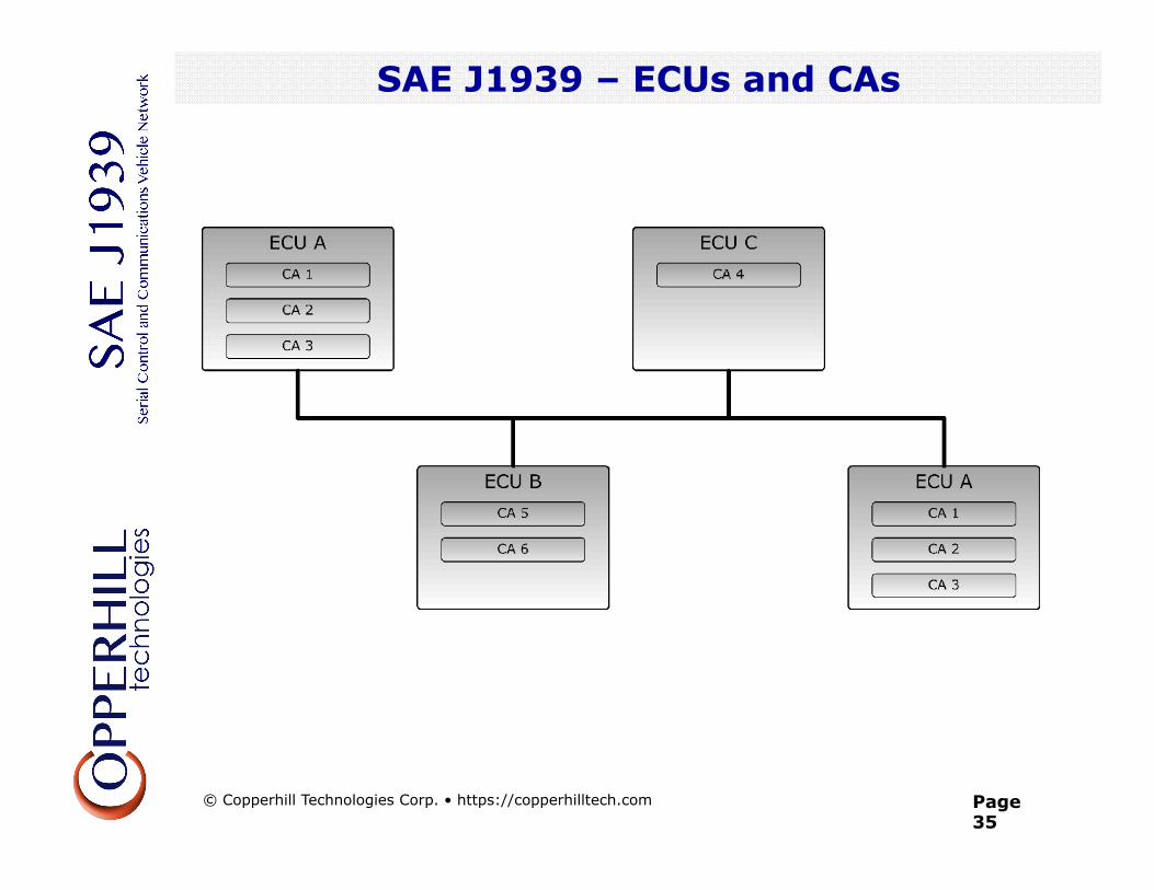
SAE J1939 – ECUs and CAs
SAE J1939 Quick Reference
© Copperhill Technologies Corp. • https://copperhilltech.com
Page 36
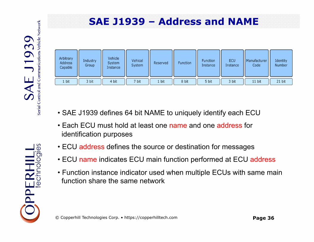
SAE J1939 – Address and NAME
• SAE J1939 defines 64 bit NAME to uniquely identify each ECU
• Each ECU must hold at least one name and one address for identification purposes
• ECU address defines the source or destination for messages
• ECU name indicates ECU main function performed at ECU address
• Function instance indicator used when multiple ECUs with same main function share the same network
SAE J1939 – Address and NAME
© Copperhill Technologies Corp. • https://copperhilltech.com
Page 37
SAE J1939 – Address Claiming
• 64 bit NAME to uniquely identify nodes (ECUs)
• Necessitates unreasonable resources to maintain standard communications
• Each ECU utilizes an 8 bit address to identify the source of a message or to access (destination address) another ECU in the network
• Address Claim Procedure:
• Designed to assign addresses to ECUs right after the network startup
• Assuring that assigned address is unique to ECU
• SAE J1939 Standard defines Preferred Addresses to commonly used devices in order to minimize the rate of multiple devices demanding the same address
SAE J1939 – Address Claiming
© Copperhill Technologies Corp. • https://copperhilltech.com
Page 38
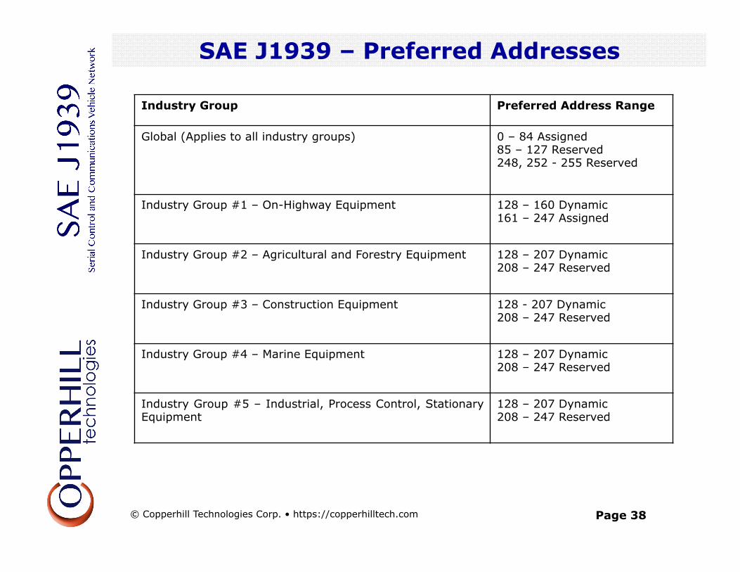
SAE J1939 – Preferred Addresses
SAE J1939 – Address Claiming
Industry Group Preferred Address Range
Global (Applies to all industry groups) 0 – 84 Assigned 85 – 127 Reserved 248, 252 - 255 Reserved
Industry Group #1 – On-Highway Equipment 128 – 160 Dynamic 161 – 247 Assigned
Industry Group #2 – Agricultural and Forestry Equipment 128 – 207 Dynamic 208 – 247 Reserved
Industry Group #3 – Construction Equipment 128 - 207 Dynamic 208 – 247 Reserved
Industry Group #4 – Marine Equipment 128 – 207 Dynamic 208 – 247 Reserved
Industry Group #5 – Industrial, Process Control, Stationary Equipment
128 – 207 Dynamic 208 – 247 Reserved
© Copperhill Technologies Corp. • https://copperhilltech.com
Page 39
SAE J1939 – Address Claiming
Two possible scenarios:
Sending an Address Claimed message (Standard)
• ECU sends Address Claimed message into the CAN bus
• ECUs receiving address claim will record & verify claimed address with internal address table
• In case of address conflict ECU with lowest NAME value will succeed
• Remaining ECUs must claim different address or stop transmitting to network
Request for Address Claimed message
• Necessary procedure for ECUs powering up late (e.g. trailers, diagnostics tools, etc.)
• Used to determine and claim available address or to find out which ECUs are currently on the network
SAE J1939 – Address Claiming
© Copperhill Technologies Corp. • https://copperhilltech.com
Page 40
SAE J1939 – Address Claiming
SAE J1939 – Address Claiming
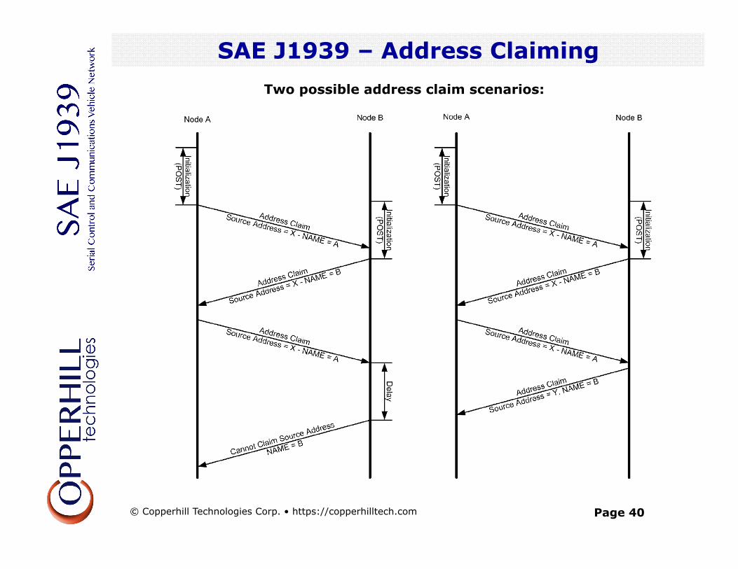
Two possible address claim scenarios:
© Copperhill Technologies Corp. • https://copperhilltech.com
Page 41
SAE J1939 – Address Claiming
SAE J1939 – Address Claiming
• Node A starts initialization and Power-On Self Test (POST) some time ahead of node B. • While node B is going through initialization and POST, node A sends out it address claim message. • Node B, after having finished initialization and POST, attempts to claim the same source address as node A • In response node A, having determined that its NAME has higher priority, resends the address claim message. • Node B receives the address claim message, determines that node A’s name has higher priority. • In the left scenario, node B sends a Cannot Claim message. In the right scenario it claims another address by sending another Address Claim message.
© Copperhill Technologies Corp. • https://copperhilltech.com
Page 42
SAE J1939 – Address Claiming
SAE J1939 – Address Claiming
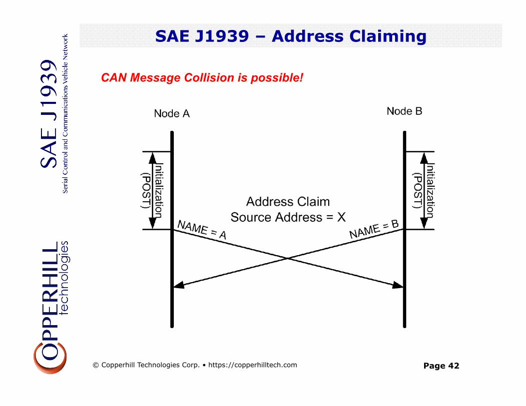
CAN Message Collision is possible!
© Copperhill Technologies Corp. • https://copperhilltech.com
Page 43
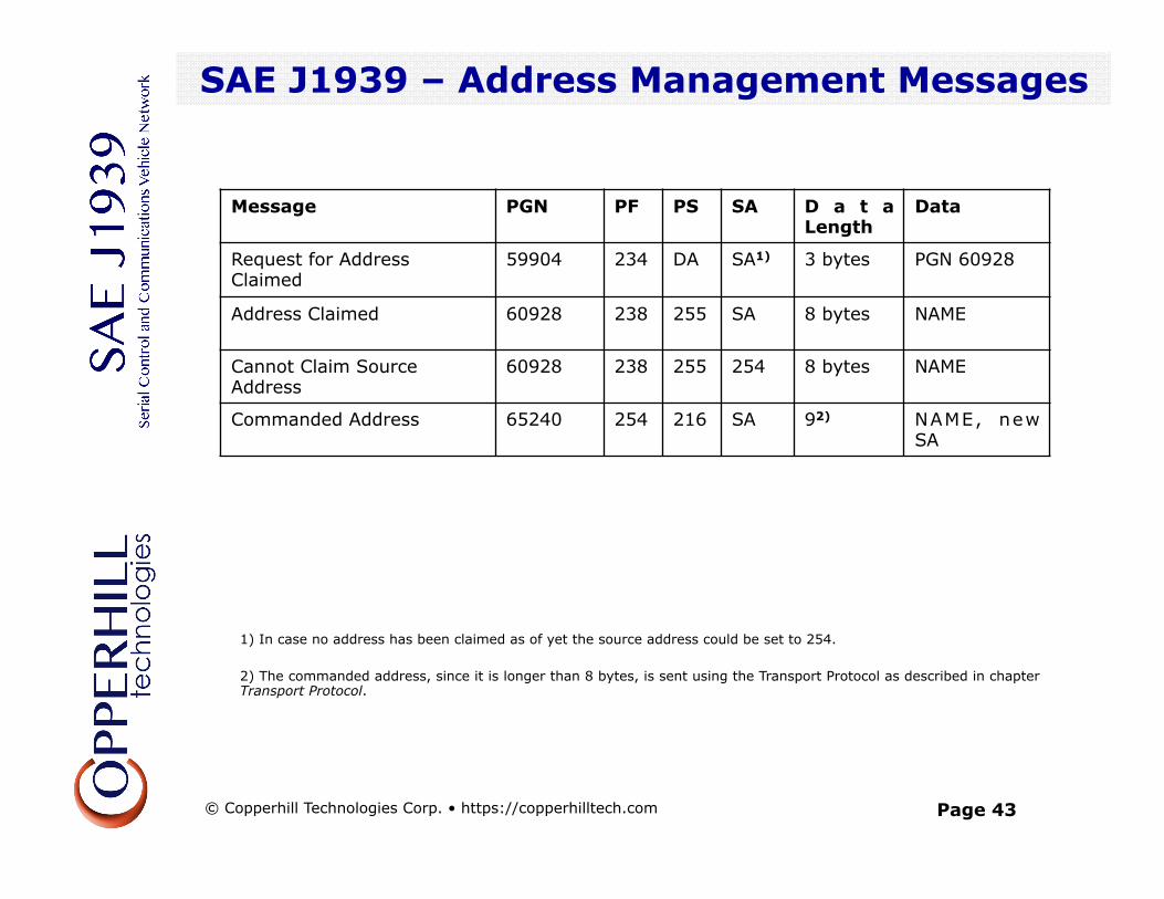
SAE J1939 – Address Management Messages
SAE J1939 – Address Claiming
Message PGN PF PS SA D a t a Length
Data
Request for Address Claimed
59904 234 DA SA1) 3 bytes PGN 60928
Address Claimed 60928 238 255 SA 8 bytes NAME
Cannot Claim Source Address
60928 238 255 254 8 bytes NAME
Commanded Address 65240 254 216 SA 92) NAME, new SA
1) In case no address has been claimed as of yet the source address could be set to 254. 2) The commanded address, since it is longer than 8 bytes, is sent using the Transport Protocol as described in chapter Transport Protocol.
© Copperhill Technologies Corp. • https://copperhilltech.com
Page 44
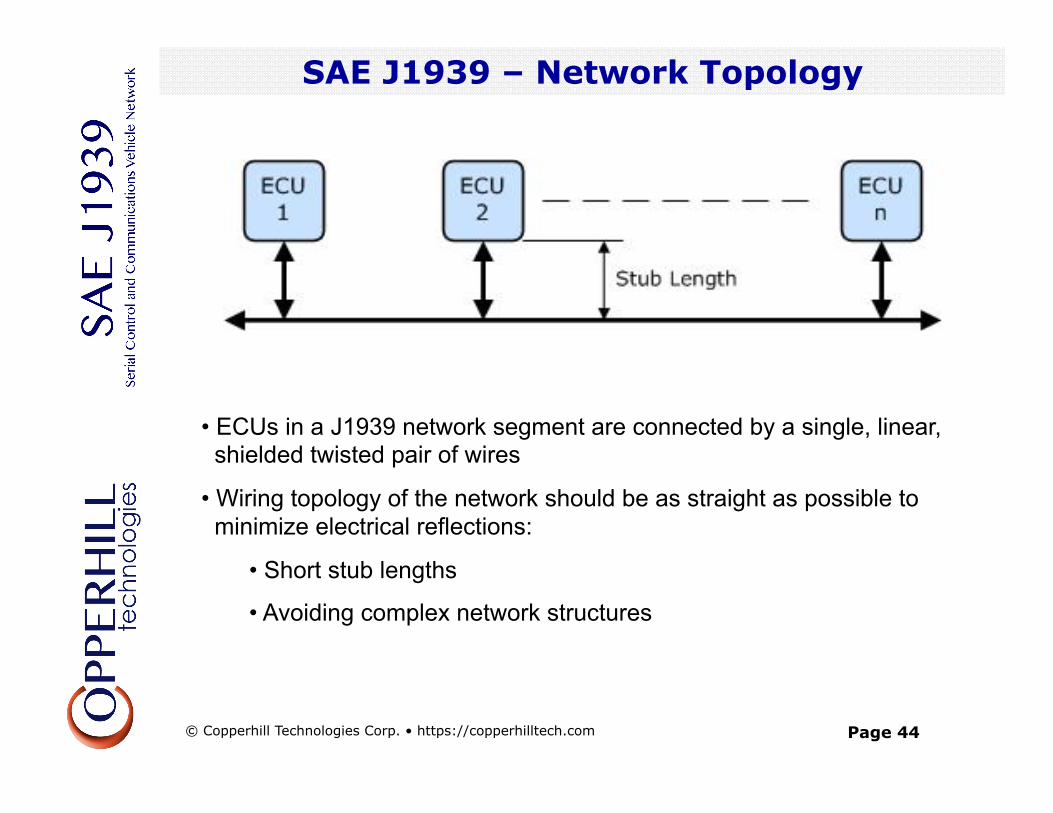
SAE J1939 – Network Topology
• ECUs in a J1939 network segment are connected by a single, linear, shielded twisted pair of wires
• Wiring topology of the network should be as straight as possible to minimize electrical reflections:
• Short stub lengths
• Avoiding complex network structures
SAE J1939 – Network Topology
© Copperhill Technologies Corp. • https://copperhilltech.com
Page 45
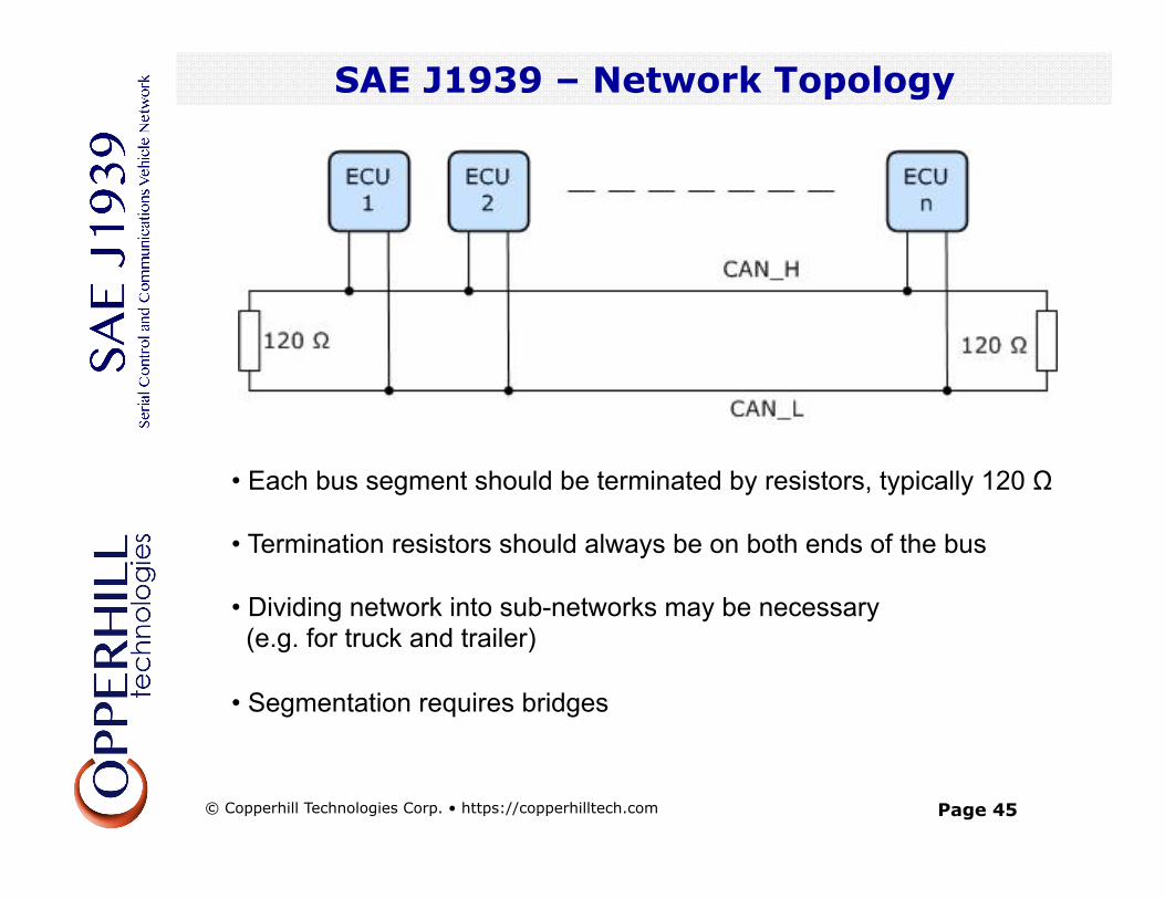
SAE J1939 – Network Topology
• Each bus segment should be terminated by resistors, typically 120 Ω • Termination resistors should always be on both ends of the bus
• Dividing network into sub-networks may be necessary (e.g. for truck and trailer)
• Segmentation requires bridges
SAE J1939 – Network Topology
© Copperhill Technologies Corp. • https://copperhilltech.com
Page 46
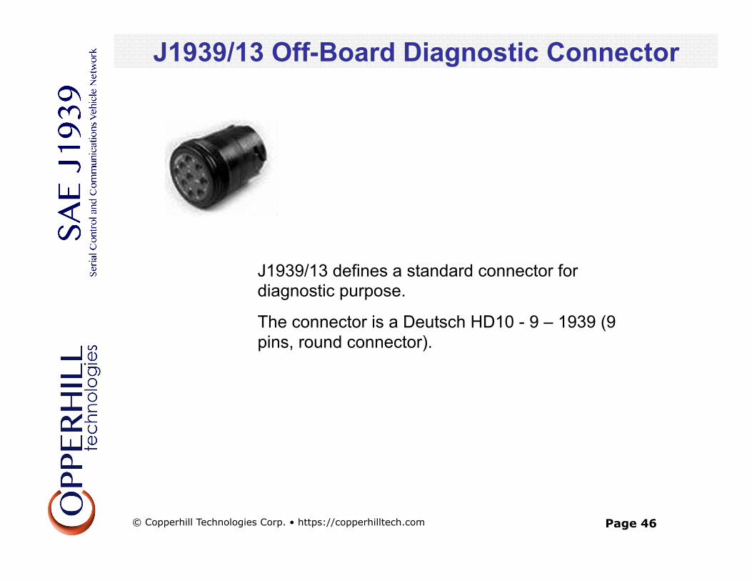
J1939/13 Off-Board Diagnostic Connector
J1939/13 defines a standard connector for diagnostic purpose.
The connector is a Deutsch HD10 - 9 – 1939 (9 pins, round connector).
J1939/13 Off-Board Diagnostic Connector
© Copperhill Technologies Corp. • https://copperhilltech.com
Page 47
Literature
Literature on Controller Area Network, CANopen and SAE J1939
https://copperhilltech.com/technical-literature/
© Copperhill Technologies Corp. • https://copperhilltech.com


![DCU 305 R3 CAN / J1939 Manual - Auto-Maskin§ [a] SAE, J1939-71 § [b] SAE, J1939-73 § [c] Conrad Etschberger, “Controller Area Network” ... CAN / J1939 Manual CAN / J1939 –](https://img.pdfslide.us/doc/110x75/5ae535d97f8b9a7b218f6863/dcu-305-r3-can-j1939-manual-auto-maskin-a-sae-j1939-71-b-sae-j1939-73.jpg)