Embed Size (px)
Citation preview

Perkins 1200F Series Models MT, MU, MV, MW, BM and BN
ELECTRONIC APPLICATION & INSTALLATION MANUAL 1204F-E44TA Four & six cylinder diesel 1204F-E44TTA engines for agricultural, 1206F-E70TA industrial, construction 1206F-E70TTA applications
1200 Series
Perkins Engines Company Limite d
Peterborough, PE1 5FQ, United Kingdom
Tel: +44 (0)1733 583000
Fax: +44 (0)1733 582240www.perkins.com
Copyright © 2014 Perkins Engines Company Limited, all rights
reserved. No part of this document may be reproduced in any form
or by any means, without prior written permission of Perkins Engines
Company Limited. The information in this document is substantially
correct at the time of printing and may be altered subsequentl y.
Publication No.TPD1836 – Production Issue 2, November 2015
Electrical & Electronic Application And Installation Manual
Production Release Version 3.0 Page 2
CONTENTS
1.0 SAFETY ............................................................................................................................... 9
1.1 WARNING – WELDING ......................................................................................................... 9 1.1.2 Warning - Electrostatic Paint Spraying ...................................................................... 9 1.1.3 Warning – Jump Starting ........................................................................................... 9
2.0 ENGINE & AFTERTREATMENT COMPONENT OVERVIEW ......................................... 10
2.1 MAIN ENGINE SENSOR AND ACTUATOR DETAIL .................................................................. 10 2.1.1 Electronic Control Module ....................................................................................... 10 2.1.2 Fuel System ............................................................................................................. 10 2.1.3 Engine Speed .......................................................................................................... 10 2.1.4 NRS (NOx Reduction System) ................................................................................ 11 2.1.5 Core Engine System ................................................................................................ 11 2.1.6 Air System ............................................................................................................... 11 2.1.7 Emissions System Assist Devices ........................................................................... 11
2.2 AFTERTREATMENT SYSTEM SENSOR & ACTUATOR DETAILS................................................ 12 2.2.1 PM Capture Devices ................................................................................................ 12 2.2.3 Selective Catalytic Reduction (SCR) Technologies ................................................ 12
2.3 SYSTEM COMPONENT DIAGRAMS & SCHEMATICS ............................................................... 13 2.3.1 1204F Engine and Aftertreatment Layout ............................................................... 13 2.3.2 1206F Engine and Aftertreatment Layout ............................................................... 16
2.4 ENGINE & AFTERTREATMENT COMPONENT LAYOUT DIAGRAMS ........................................... 18 2.4.1 1204F Principal Engine Electronic Components ..................................................... 18 2.4.2 1206F Principal Engine Electronic Components ..................................................... 21 2.4.3 1204F AT Principal Components ............................................................................. 24 2.4.4 1206F AT Principal Components ............................................................................. 25
3.0 CUSTOMER SYSTEM OVERVIEW KEY ELEMENTS ..................................................... 26
3.1 AFTERTREATMENT CONFIGURATIONS ................................................................................. 26 3.2 TIER 4F MANDATORY INSTALL COMPONENTS ..................................................................... 26 3.3 OPTIONAL CUSTOMER INSTALLED COMPONENTS ................................................................ 27
4.0 POWER & GROUNDING CONSIDERATIONS ................................................................ 28
4.1 SYSTEM GROUNDING ........................................................................................................ 28 4.1.1 Ground Stud On Starter Motor ................................................................................ 28 4.1.2 Engine Block Ground Connection ........................................................................... 28 4.1.3 Aftertreatment System Grounding ........................................................................... 29
4.2 SYSTEM VOLTAGE & CURRENT REQUIREMENTS ................................................................. 30 4.2.1 Engine ECM ............................................................................................................. 30 4.2.2 1204F DEF System ................................................................................................. 31 4.2.3 1206F DEF System ................................................................................................. 31 4.2.4 System Effect on Alternator Specification ............................................................... 31
4.3 ECM POWER SUPPLY & CIRCUIT RESISTANCE ................................................................... 32 4.3.1 Important Voltage Supply Circuit Considerations .................................................... 33 4.3.2 Battery (+) Connection ............................................................................................. 34 4.3.3 Battery (-) Connection .............................................................................................. 35 4.3.4 Correct method of ECM battery connection. ........................................................... 36 4.3.5 Incorrect method of ECM battery connection. ......................................................... 36
4.4 ENGINE ECM POWER SUPPLY CIRCUIT RESISTANCE TEST ................................................. 37 4.4.1 Test Procedure ........................................................................................................ 38
4.5 DEF SYSTEM POWER SUPPLY .......................................................................................... 39 4.5.1 1204F DEF System Power Supply connection ....................................................... 39 4.5.2 1206F DEF System Power Supply Connection ....................................................... 40
4.6 SUPPRESSION OF VOLTAGE TRANSIENTS ........................................................................... 40 4.6.1 Suppression Methods & Best Practice .................................................................... 40
4.7 DIRECT BATTERY CONNECTION REQUIREMENTS ................................................................. 42 4.8 POWERING THE ENGINE ECM VIA AUXILIARY POWER SUPPLIES ......................................... 42 4.9 SENSOR COMMON CONNECTIONS...................................................................................... 42
Electrical & Electronic Application And Installation Manual
Production Release Version 3.0 Page 3
4.9.1 Actuator Driver Return ............................................................................................. 42 4.9.2 Analogue Sensor Return ......................................................................................... 43 4.9.3 Switch Return .......................................................................................................... 43 4.9.4 Digital Return ........................................................................................................... 43
5.0 CONNECTORS & WIRING HARNESS REQUIREMENTS .............................................. 44
5.1 ENGINE ECM J1 CONNECTOR ........................................................................................... 44 5.1.1 J1 Connector Layout................................................................................................ 44 5.1.2 Tightening The OEM Connector .............................................................................. 45 5.1.3 ECM Connector Wire Gauge Sealing Capability ..................................................... 45 5.1.4 Hand Crimping For Prototype machines ................................................................. 45 5.1.5 ECM connector sealing plug installation guidelines ................................................ 45 5.1.6 OEM harness Dress Cover With Integrated Strain Relief ....................................... 45 5.1.7 Machine Crimping For High Volume Production ..................................................... 46
5.2 ENGINE ECM J1 CONNECTOR I/O ..................................................................................... 46 5.3 ECM CONNECTOR ASSEMBLY & DISASSEMBLY .................................................................. 48
5.3.1 Connector Assembly ................................................................................................ 48 5.3.2 Connector Disassembly ........................................................................................... 50
5.4 DIAGNOSTIC CONNECTOR ................................................................................................. 51 5.4.1 Diagnostic Connector Layout .................................................................................. 51 5.4.2 Diagnostic Connector Wire Gauge Size .................................................................. 51 5.4.3 Pin Information ......................................................................................................... 52
5.5 MANDATORY ENGINE & AFTERTREATMENT CONNECTORS ................................................... 53 5.6 CONNECTOR TERMINAL CONTACTS ................................................................................... 53 5.7 WIRE SPECIFICATION REQUIREMENTS ............................................................................... 54
5.7.1 Wire Thickness Overview ........................................................................................ 54 5.8 HARNESS WIRING STANDARDS .......................................................................................... 55
5.8.1 Connectors .............................................................................................................. 55 5.8.2 Harness Bends Near Connectors ............................................................................ 55 5.8.3 Cable routing ........................................................................................................... 56 5.8.4 Electromagnetic Compatibility (EMC) ...................................................................... 56 5.8.5 Insulation Selection and Thermal Protection ........................................................... 57
6.0 CUSTOMER CONNECTION OF ENGINE COMPONENTS ............................................. 58
6.1 WATER IN FUEL SWITCH ................................................................................................... 58 6.1.1 WIF Switch Operation .............................................................................................. 58 6.1.2 WIF Switch Configuration ........................................................................................ 58 6.1.3 WIF Switch Installation ............................................................................................ 58
6.2 AMBIENT AIR TEMPERATURE SENSOR ................................................................................ 59 6.2.1 Ambient Air Temperature Sensor Operation ........................................................... 59 6.2.2 Ambient Air Temperature Sensor Configuration ..................................................... 59 6.2.3 Ambient Air Temperature Sensor Installation .......................................................... 59
6.3 ENGINE ELECTRICAL FUEL LIFT PUMP ................................................................................ 60 6.3.1 Engine Electrical Fuel Lift Pump Operation ............................................................. 60 6.3.2 Engine Electrical Fuel Lift Pump Configuration ....................................................... 61 6.3.3 Engine Electrical Fuel Lift Pump Installation ........................................................... 61
7.0 1204F CONNECTING TO THE ENGINE AFTERTREATMENT ....................................... 64
7.1 DOC + DPF + SCR ......................................................................................................... 64 7.1.1 System Architecture ................................................................................................. 64 7.1.2 Electrical Connections ............................................................................................. 65 7.1.3 Component I/O ........................................................................................................ 67
7.2 DOC + SCR .................................................................................................................... 68 7.2.1 System Architecture ................................................................................................. 68 7.2.2 Electrical Connections ............................................................................................. 68 7.2.3 Component I/O ........................................................................................................ 70
7.3 1204F DEF SYSTEM ........................................................................................................ 71 7.3.1 System Architecture ................................................................................................. 71 7.3.2 PEU Electrical Connections & Component Installation Requirements .................... 72 7.3.3 Component I/O ........................................................................................................ 77
Electrical & Electronic Application And Installation Manual
Production Release Version 3.0 Page 4
7.4 1204F AFTERTREATMENT WIRING SCHEMATICS ................................................................. 79 7.4.1 1204F DOC & SCR Schematic ................................................................................ 79 7.4.2 1204F DOC, DPF & SCR Schematic ...................................................................... 80
8.0 1206F CONNECTING TO THE ENGINE AFTERTREATMENT ....................................... 81
8.1 IG CEM ........................................................................................................................... 81 8.1.1 System Architecture ................................................................................................. 81 8.1.2 IG CEM Electrical Connections ............................................................................... 83 8.1.3 Component I/O ........................................................................................................ 84
8.2 1206F PUMP ELECTRONICS & TANK UNIT (PETU) ............................................................. 86 8.2.1 PETU System Architecture ...................................................................................... 86 8.2.2 PETU Electrical Connections & Component Installation Requirements ................. 87 8.2.3 Component I/O ........................................................................................................ 94
8.3 1206F AFTERTREATMENT WIRING SCHEMATIC .................................................................. 96
9.0 COMPONENT INSTALLATION REQUIREMENTS .......................................................... 97
9.1 DPF SOOT SENSOR .......................................................................................................... 97 9.1.1 DPF Soot Sensor Operation .................................................................................... 97 9.1.2 DPF Soot Sensor Configuration .............................................................................. 97 9.1.3 DPF Soot Sensor Installation .................................................................................. 97
9.2 NOX SENSOR ................................................................................................................. 101 9.2.1 NOx Sensor Operation .......................................................................................... 101 9.2.2 NOx Sensor Configuration ..................................................................................... 101 9.2.3 NOx Sensor Installation ......................................................................................... 102
9.3 AMMONIA (NH3)SENSOR ................................................................................................ 106 9.3.1 Ammonia (NH3) Sensor Operation ........................................................................ 106 9.3.2 Ammonia (NH3) Sensor Configuration .................................................................. 106 9.3.3 Ammonia (NH3) Sensor Installation ...................................................................... 106
9.4 DPF IN AND SCR PERKINSIN COMBINED TEMP SENSOR (1206F) ..................................... 109 9.4.1 DPF & SCR Temp Sensor Operation .................................................................... 109 9.4.2 DPF & SCR Temp Sensor Configuration .............................................................. 109 9.4.3 DPF & SCR Temp Sensor Installation ................................................................... 109
9.5 IG CEM ID MODULE ....................................................................................................... 111 9.5.1 IG CEM ID Module Operation ................................................................................ 111 9.5.2 IG CEM ID Module Configuration .......................................................................... 111 9.5.3 IG CEM ID Module Installation .............................................................................. 111
9.6 DOC, DPF & SCR INLET TEMPERATURE SENSORS (1204F) ............................................ 114 9.6.1 DOC, DPF & SCR Inlet Temperature Sensor Operation ....................................... 114 9.6.2 DOC, DPF & SCR Inlet Temperature Sensor Configuration ................................. 114 9.6.3 DOC, DPF & SCR Inlet Temperature Sensor Installation ..................................... 114
10.0 STARTING AND STOPPING THE ENGINE ................................................................. 116
10.1 STARTING THE ENGINE .................................................................................................. 116 10.2 STOPPING THE ENGINE (AND PREVENTING RESTART) ..................................................... 117
10.2.1 Ignition Keyswitch ................................................................................................ 117 10.2.2 Battery Isolation Switches ................................................................................... 118 10.2.3 User Defined Shutdown Switch (Remote Shutdown) .......................................... 118 10.2.4 Delayed Engine Shutdown (1206F Only) ............................................................ 119 10.2.5 Engine Low Idle Shutdown .................................................................................. 119 10.2.6 Intake Air Shutoff Valve ....................................................................................... 122 10.2.7 Overspeed Verify Switch ..................................................................................... 123 10.2.8 Datalink stops ...................................................................................................... 123 10.2.9 Engine Emergency Stops .................................................................................... 123 10.2.10 Common problems with the application of stop devices ................................... 124
11.0 ENGINE COOLING FAN CONTROL ............................................................................ 125
11.1 HYDRAULIC FAN CONTROL ............................................................................................ 125 11.1.1 Hydraulic Fan Control Operation ......................................................................... 125 11.1.2 Hydraulic Fan Control Configuration ................................................................... 125 11.1.3 Hydraulic Fan control Installation ........................................................................ 127
Electrical & Electronic Application And Installation Manual
Production Release Version 3.0 Page 5
12.0 ENGINE SPEED DEMAND ........................................................................................... 129
12.1 ANALOGUE SENSOR ...................................................................................................... 130 12.1.1 Analogue Sensor Operation ................................................................................ 130 12.1.2 Analogue Sensor Configuration ........................................................................... 130 12.1.3 Analogue Sensor Installation ............................................................................... 131 12.1.4 Evaluating Component Compatibility (Testing) ................................................... 131
12.2 PWM SENSOR - COMPATIBILITY ................................................................................... 134 12.2.1 PWM Sensor Operation ....................................................................................... 134 12.2.2 PWM Sensor Configuration ................................................................................. 135 12.2.3 PWM Sensor Installation ..................................................................................... 135
12.3 THROTTLE LOCK (PTO MODE) ....................................................................................... 136 12.3.1 Throttle Lock Mode Operation ............................................................................. 136 12.3.2 Throttle Lock Mode Configuration ....................................................................... 139 12.3.3 Throttle Lock Mode Installation ............................................................................ 139 12.3.4 Throttle Lock Operation Under Engine Load ....................................................... 139
12.4 MULTI POSITION THROTTLE SWITCH (MPTS) ................................................................. 141 12.4.1 MPTS Operation .................................................................................................. 141 12.4.2 MPTS Configuration ............................................................................................ 142 12.4.3 MPTS Installation ................................................................................................. 142
12.5 TORQUE SPEED CONTROL TSC1 (SPEED CONTROL OVER CAN) ................................... 143 12.6 ARBITRATION OF SPEED DEMAND ................................................................................... 143
12.6.1 Manual Throttle Selection Switch ........................................................................ 143 12.7 ACCELERATION AND DECELERATION RAMP RATES ......................................................... 143 12.8 THROTTLE BEHAVIOUR DURING ENGINE GOVERNOR CHANGES ....................................... 143 12.9 ENGINE LIMP HOME SPEED ........................................................................................... 144 12.10 THROTTLE CALIBRATION ............................................................................................. 144
12.10.1 Throttle Parameter Description .......................................................................... 146 11.10.2 Throttle Calibration Function ............................................................................. 147 12.10.3 Idle Validation Switch......................................................................................... 151
12.11 DEFINITION OF ENGINE SPEED POINTS ........................................................................ 152 12.11.1 Engine Low Idle ................................................................................................. 152 12.11.2 Engine High Idle ................................................................................................ 153 12.11.3 Engine Rated Speed ......................................................................................... 153
13.0 COLD WEATHER ENGINE OPERATION & STARTING AIDS ................................... 154
13.1 CONTROL OF GLOW PLUGS BY THE ENGINE ECM .......................................................... 156 13.1.1 Glow Plug System Operation .............................................................................. 156 13.1.2 Glow Plug System Configuration ......................................................................... 158 13.1.3 Glow Plug System Installation ............................................................................. 158
13.2 ETHER COLD START SYSTEMS ...................................................................................... 160 13.2.1 Ether start Operation ........................................................................................... 160 13.2.2 Ether start Configuration ...................................................................................... 160 13.2.3 Ether start Installation .......................................................................................... 160
13.3 HEATED BREATHER ...................................................................................................... 162 13.3.1 Heated Breather Operation ................................................................................. 162 13.3.2 Heated Breather Configuration ............................................................................ 162 13.3.3 Heated Breather Installation ................................................................................ 163
13.4 COLD WEATHER REGENERATION AID ............................................................................. 164 13.4.1 Cold Weather Regeneration Aid Operation ......................................................... 164 13.4.2 Cold Weather Regeneration Aid Configuration ................................................... 164 13.4.3 Cold Weather Regeneration Aid Installation ....................................................... 164
13.5 EXTREME LOW TEMPERATURE AFTERTREATMENT AMBIENT AIR TEMPERATURE SENSOR . 165 13.5.1 Aftertreatment Ambient Air Temperature Sensor Operation ............................... 165 13.5.2 Aftertreatment Ambient Air Temp Sensor Configuration ..................................... 165 13.5.3 Aftertreatment Ambient Air Temp Sensor Installation ......................................... 165
13.6 ENGINE SOFT START PROTECTION ................................................................................ 166 13.6.1 Engine Soft Start Protection Operation ............................................................... 166 13.6.2 Engine Soft Start Protection Configuration .......................................................... 166 13.6.3 Engine Soft Start Protection Installation .............................................................. 166
Electrical & Electronic Application And Installation Manual
Production Release Version 3.0 Page 6
14.0 OPERATOR INDICATORS & FAULT DISPLAYS ....................................................... 167
14.1 ENGINE & AT DIAGNOSTIC SYSTEMS ............................................................................. 167 14.1.1 Monitoring System Fault Status Levels ............................................................... 167
14.2 GAUGE DRIVERS ........................................................................................................... 168 14.2.1 Datalink Driven Intelligent Displays ..................................................................... 169 14.2.2 Minimum Functional Specification for J1939 display. .......................................... 169
14.3 LAMP OUTPUTS & OPERATION ....................................................................................... 169 14.3.1 Hardwired Lamp Outputs ..................................................................................... 169 14.3.2 J1939 Indicator Support ...................................................................................... 170 14.3.3 Indicator ISO Reference Symbols ....................................................................... 171 14.3.4 Engine Shutdown Indicator .................................................................................. 172 14.3.5 Engine Warning Indicator .................................................................................... 173 14.3.6 Engine Wait To Start Indicator ............................................................................. 173 14.3.7 Oil Pressure Indicator .......................................................................................... 174 14.3.8 Emissions System Malfunction Indicator ............................................................. 174 14.3.9 Low DEF Level Indicator ..................................................................................... 175 14.3.10 Wait To Disconnect Indicator ............................................................................. 175 14.3.11 Delayed Engine Shutdown Active Indicator (1206F Only) ................................ 176
15.0 ENGINE & AFTERTREATMENT MONITORING SYSTEM .......................................... 177
15.1 GENERAL INFORMATION ................................................................................................ 177 15.1.1 Monitoring Levels ................................................................................................. 177 15.1.2 Parameter Severity Levels .................................................................................. 178 15.1.3 Monitoring System Example ................................................................................ 179
15.2 NON EMISSIONS CRITICAL COMPONENT MONITORING & PROTECTION ............................. 180 15.2.1 Coolant Temperature ........................................................................................... 180 15.2.2 Engine Oil Pressure ............................................................................................. 180 15.2.3 Intake Manifold Temperature ............................................................................... 181 15.2.4 Engine Overspeed ............................................................................................... 182 15.2.5 High NRS Temperature ....................................................................................... 183
15.3 EMISSIONS CRITICAL COMPONENTS MONITORING & PROTECTION ................................... 184 15.3.1 Inducement Strategy High Level Overview ......................................................... 184 15.3.2 Combined EU/EPA Inducement Strategy Operation ........................................... 184 15.3.3 Combined EU/EPA Inducement Strategy Configuration ..................................... 189 15.3.4 Repeat Occurrence and Final Inducement Handling .......................................... 190 15.3.5 Final Inducement Safe Harbor Mode. .................................................................. 190 15.3.6 Engine First Fit Inducement Activation ................................................................ 190 15.3.7 Emergency Inducement Override Strategy ......................................................... 191
16.0 MONITORED INPUTS FOR CUSTOMER FITTED SENSORS .................................... 192
16.1 AIR FILTER SERVICE INDICATOR – AIR INTAKE RESTRICTION SWITCH .............................. 193 16.1.1 Air Intake Restriction Switch Operation ............................................................... 193 16.1.2 Air Intake Restriction Switch Configuration ......................................................... 193 16.1.3 Air Intake Restriction Switch Installation.............................................................. 193
16.2 COOLANT LEVEL SWITCH .............................................................................................. 194 16.2.1 Coolant Level Switch Operation .......................................................................... 194 16.2.2 Coolant Level Switch Configuration ..................................................................... 194 16.2.3 Coolant Level Switch Installation ......................................................................... 195
16.3 AUXILIARY TEMPERATURE SENSOR................................................................................ 195 16.3.1 Auxiliary Temperature Sensor Operation ............................................................ 195 16.3.2 Auxiliary Temperature Sensor Configuration ...................................................... 196 16.3.3 Auxiliary temperature Sensor Installation ............................................................ 196
16.4 AUXILIARY PRESSURE SENSOR ..................................................................................... 197 16.4.1 Auxiliary Pressure Sensor Operation .................................................................. 197 16.4.2 Auxiliary Pressure Sensor Configuration ............................................................. 197 16.4.3 Auxiliary pressure Sensor Installation ................................................................. 198
17.0 AFTERTREATMENT SYSTEM MACHINE INTEGRATION ......................................... 199
17.1 AFTERTREATMENT SYSTEM OPERATION ........................................................................ 199 17.1.1 DOC Operation .................................................................................................... 199
Electrical & Electronic Application And Installation Manual
Production Release Version 3.0 Page 7
17.1.2 DPF Operation ..................................................................................................... 199 17.1.3 SCR Operation .................................................................................................... 199
17.2 LOW TEMPERATURE AFTERTREATMENT REGENERATION SYSTEM ................................... 199 17.2.1 Low Speed Regeneration Operation 1204F DOC + SCR only ........................... 199 17.2.2 Low Temperature Regeneration Operation 1204F & 1206F DOC, DPF + SCR Products .......................................................................................................................... 200 17.2.3 Engine Elevated Idle (Mandatory Installation) ..................................................... 202 17.2.4 Machine Integration Of Elevated Idle .................................................................. 203
17.3 DEF SYSTEM OPERATION ............................................................................................. 205 17.4 DEF SYSTEM MACHINE INTERFACE REQUIREMENTS ...................................................... 207
17.4.1 Delayed Engine Shutdown (1206F Only) ............................................................ 207 17.4.2 System Purge ...................................................................................................... 211 17.4.3 DEF Thaw ............................................................................................................ 217 17.4.4 Operator Indicators and Displays ........................................................................ 218
18.0 ENGINE GOVERNOR ................................................................................................... 219
18.1 MIN / MAX GOVERNING ................................................................................................. 219 18.1.1 Min / Max Governing Operation ........................................................................... 219 18.1.2 Min / Max Governing Configuration ..................................................................... 220 18.1.3 Min / Max Governing Installation ......................................................................... 220
18.2 ENGINE ALL SPEED GOVERNING .................................................................................... 221 18.2.1 Engine All Speed Governing Operation............................................................... 221 18.2.3 Engine All Speed Governing Configuration ......................................................... 222 18.2.3 Engine All Speed Governing Installation ............................................................. 222
18.3 RATING SELECTION USING EST .................................................................................... 223 18.4 ENGINE HIGH SPEED GOVERNOR (GOVERNOR RUN-OUT) .............................................. 223
18.4.1 Engine High Speed Governor Operation ............................................................. 223 18.4.2 Engine High Speed Governor Configuration ....................................................... 223
18.5 MODE SELECTION ......................................................................................................... 223 18.5.1 Mode Selection Operation ................................................................................... 223 18.5.2 Mode Selection Configuration ............................................................................. 224 18.5.3 Installation ............................................................................................................ 224 18.5.4 Rating and Droop changes requested via the J1939 datalink ............................. 224
19.0 DATALINK SUPPORT .................................................................................................. 225
19.1 SAE J1939 .................................................................................................................. 225 19.1.1 Summary of Key J1939 Application Issues ......................................................... 225 19.1.2 Physical layer ....................................................................................................... 225 19.1.3 Network Layer ...................................................................................................... 225 19.1.4 Application Layer ................................................................................................. 226
19.2 CONNECTION AND USE OF THE J1939 CAN BUS ............................................................ 227
20.0 J1939 SUPPORTED PARAMETERS QUICK REFERENCE ....................................... 228
21.0 J1939 PARAMETERS – DETAILED DESCRIPTIONS ................................................ 237
21.1 SENDING MESSAGES TO THE ENGINE ECM .................................................................... 237 21.1.1 Source Addressing .............................................................................................. 237 21.1.2 Destination Addressing ........................................................................................ 237
21.2 J1939 SECTION 71 – TSC1 OPERATION ........................................................................ 238 21.2.1 Torque Speed Control (TSC1) Operating Principles ........................................... 238 21.2.2 Torque Speed Control (TSC1) Message Configuration & Control ...................... 240
APPENDIX ............................................................................................................................. 242
APPENDIX 1 COMPLETE SYSTEM CONNECTOR LISTS .............................................................. 242 1204F Connector Parts List ............................................................................................ 242 1206F Connector Parts List ............................................................................................ 244
APPENDIX 2 UPDATE TRACKER .............................................................................................. 246
Electrical & Electronic Application And Installation Manual
Production Release Version 3.0 Page 8
The information contained in this manual is confidential and proprietary to Perkins. It is intended for circulation only to Perkins employees, or to employees of OEMs intending to purchase and install Tier 4 Final/EU Stage IV Perkins engines in their equipment. Distribution of this material must be limited to personnel whose duties require knowledge of such material and is intended exclusively for their information and training. Distribution of this material for other purposes is strictly prohibited. A&I Manual Introduction This manual has been compiled to explain mandatory requirements, provide information for designers, and provide information on the application and installation of the 1204F-1206F engines into industrial equipment, to meet U.S. Environmental Protection Agency (EPA) Tier 4 Final and European Union (EU) Stage IV emission standards. Serial number prefixes for the engines referenced in this manual are: 1204F : MT, MU, MW & MV 1206F : BM & BN The following media publications for the relevant engine type should also be used for further technical information:
• 1204F-1206F Application and Installation Manual TPD1830
• 1204F DEF System Supplement TPD1832
• 1206F DEF System Supplement TPD1834
• Operator and Maintenance Manual (OMM)
• System Operation Test and Adjust (SOTA)
• Disassembly and Assembly (D&A)
• Engine Specification Manual (ESM) Always follow correct practices, procedures, and safety precautions. Please note: The information provided may be subject to change. Perkins has provided this information in good faith and is not liable for how this information is interpreted or applied. Perkins is not responsible for failures resulting from attachments, systems, accessory items, and parts not sold or approved by Perkins. Consult the applicable warranties for complete details of the Perkins warranty coverage. The OEM and customer are reminded that it is their responsibility to ensure compliance with the requirements of any applicable employee health and safety laws and regulations, both nationally and internationally, in relation to the engine installation applicable to the equipment concerned. In giving notice of approval in respect to the installation, Perkins does not assume such responsibilities on behalf of the OEM or customer and while engine installation approval and advice is an opinion given in good faith, the equipment manufacturer and customer remain responsible as detailed above and must act and insure accordingly.
Electrical & Electronic Application And Installation Manual
Production Release Version 3.0 Page 9
1.0 Safety Most accidents that involve product operation, maintenance and repair are caused by failure to observe basic safety rules or precautions. An accident can often be avoided by recognizing potentially hazardous situations before an accident occurs. A person must be alert to potential hazards. This person should also have the necessary training, skills and tools in order to perform these functions properly. The information in this publication was based upon current information at the time of publication. Check for the most current information before you start any job. Perkins distributors will have the most current information. Improper operation, maintenance or repair of this product may be dangerous. Improper operation, maintenance or repair of this product may result in injury or death. Do not operate or perform any maintenance or repair on this product until you have read and understood the operation, maintenance and repair information. Perkins cannot anticipate every possible circumstance that might involve a potential hazard. The warnings in this publication and on the product are not all inclusive. If a tool, a procedure, a work method or an operating technique that is not specifically recommended by Perkins is used, you must be sure that it is safe for you and for other people. You must also be sure that the product will not be damaged and / or made unsafe by the procedures that are used.
1.1 Warning – Welding Welding can cause damage to the on engine electronics. The following precautions should be taken before and during welding:
• Turn the engine OFF. Place the ignition keyswitch in the OFF position
• Disconnect the negative battery cable from the battery. If the machine is fitted with a battery disconnect switch then open the switch
• Clamp the ground cable of the welder to the component that will be welded. Place the clamp as close as possible to the weld.
• Protect any wiring harnesses from welding debris and splatter.
1.1.2 Warning - Electrostatic Paint Spraying The high voltages used in electrostatic paint spraying can cause damage to on engine electronics. The damage can manifest itself through immediate failure of components, or by weakening electronic components causing them to fail at a later date. The following precautions should be taken when using electrostatic paint spraying techniques on engines:
• Connect all 86 pins of the ECM J1 Connector directly to the spraying booth ground.
• Connect the engine block to ground at 2 points. Ensure that good screwed connections onto bright metal are used.
1.1.3 Warning – Jump Starting Jump-starting an engine can cause higher than normal voltages to appear across the battery terminals. Care must be taken that this does not exceed the recommended maximum voltage for the ECM.
Electrical & Electronic Application And Installation Manual
Production Release Version 3.0 Page 10
2.0 Engine & Aftertreatment Component Overview
2.1 Main Engine Sensor and Actuator Detail
2.1.1 Electronic Control Module
The A5:E2v2 & A5:E12 ECMs are electronic control devices that govern engine speed, torque output and manage the engines performance and emissions via a number of sensors and actuators. The Engine ECM is supplied with each engine and the variant is dependent upon the system voltage selected. The ECM is situated on the left hand side rear of the engine. The device has two connection sockets, one for the engine wiring harness (J2) and the other for the OEM machine wiring harness (J1). Two versions of the A5:E2v2 ECM are available a fuel cooled and air cooled, the choices of which depends upon the maximum ambient temperature the unit will be exposed to (see mechanical installation guide for details of fuel system connection requirements and temperature restrictions).
2.1.2 Fuel System
The engine fuel system comprises of an electronic lift pump, high pressure fuel pump, electronically controlled unit injectors and a High pressure fuel rail to feed the injectors. The electrical lift pump is used to provide a constant flow of fuel to the engine fuel pump. This pump also provides the user with an electrical priming feature. The fuel pump provides high pressure fuel to the fuel rail. The engine ECM via the fuel pump solenoid controls this fuel pump delivery and the resulting rail pressure. The engine ECM controls the fuel pump solenoid control based upon the inputs received from the fuel temperature sensor (which enables the control to be tailored to the specific fuel characteristics) and the fuel rail pressure sensor (which measures the actual pressure within the fuel rail). Note: for more information regarding the electrical fuel lift pump and priming feature please see the mechanical A&I Guide and section 6.3 of this document for electrical installation requirements. High pressure fuel is delivered to each of the electronically controlled unit injectors which when activated by the engine ECM deliver a controlled measure of fuel for combustion. Voltages applied by the ECM to activate the injectors are high around 70V and the OEM must ensure that any systems sensitive to electromagnetic radiation are not close proximity to the harness components that lead to the injectors. The engine fuel system is also fitted with a water in fuel switch mounted within the primary filter bowl. This switch is mandatory for all Tier 4 engines to indicate to the operator that the filter water trap is full and needs emptying. This switch is supplied with the engine from the factory but it is the customer’s responsibility to connect this component to the ECM J1 connector via the machine wiring harness. It should be noted that in many cases a fault on any of these sensors, solenoids or switches will cause the engine to derate, or enter a limp home state due to their emissions critical nature.
2.1.3 Engine Speed
The engine is fitted with two Hall effect speed sensors. The first is mounted on the engine to measure the crank speed and position and the other is used to measure the cam shaft speed, position and engine cycle. The engine uses the crank speed signal during normal engine operation as this signal is more accurate at higher speeds. If the crank shaft speed signal is lost during engine running then the engine will enter a derate condition, however if the engine is cranking the engine will start but be limited to a programmed derate. The cam shaft speed sensor is used to calculate the engine cycle during engine starting and for limp home operation. For this reason if the camshaft speed timing sensor signal is lost the engine will not start, but if the engine is running a fault code will be raised and the engine will continue to run normally.
Electrical & Electronic Application And Installation Manual
Production Release Version 3.0 Page 11
2.1.4 NRS (NOx Reduction System)
The NOx reduction system is made up of the following components;
• NRS Intake Absolute Pressure Sensor
• NRS Differential Pressure Sensor
• NRS Temperature Sensor
• NRS metering Valve Both the temperature and pressure sensor measurements are required by the engine control system to control NRS metering valve. The metering valve controls the mass air flow through the NOx reduction system cooler by means of a DC motor and a position sensor. This part of the engine control system is emissions critical and for this reason the engine may apply a derate if any of these components enter a fault condition.
2.1.5 Core Engine System There are a number of core engine operation sensors that are used to determine how the engine control system should respond to various conditions. These components include the barometric sensor, coolant temperature sensor and the oil pressure sensor. The barometric sensor is located near the ECM. The sensor is used to determine atmospheric (barometric) pressure. The atmospheric pressure is used to determine the atmospheric related fuel limits (if any) e.g. at high altitude fuel may be limited during cranking to prevent turbo overspeed. The coolant temperature sensor measurement is used as an input to the cold start strategy. The sensor reading is also used to determine fuel limits and injection timing at various temperatures to control engine emissions. The oil pressure sensor measures engine oil pressure in kPa. Oil pressure is used for engine protection whereby if insufficient oil pressure is measured for a given speed, an event for low oil pressure would be raised.
2.1.6 Air System The engine air system contains the following electronic components.
• Intake Manifold Temperature Sensor
• Intake Manifold Pressure Sensor
• Turbocharger Wastegate Regulator The intake manifold pressure sensor measures the air pressure inside the intake manifold, after the turbo and NRS mixer. There are two sensor options dependent upon the choice of rating. The pressure sensor is used in a number of engine management control strategies contained within the engine ECM. The intake manifold temperature sensor measures the temperature of the mixed air inside the inlet manifold. The sensor measurement range is –40 to 150°C The regulator valve controls the pressure in the intake manifold to a value that is determined by the ECM. The wastegate regulator provides the interface between the ECM and the mechanical system that regulates intake manifold pressure to the desired value that is determined by the engine software.
2.1.7 Emissions System Assist Devices
The 1204 and 1206 Tier 4 Final product range are fitted with exhaust back pressure valve that are used to provide engine exhaust temperature management for a number of engine control strategies including Aftertreatment regeneration. The exhaust back pressure valve is
Electrical & Electronic Application And Installation Manual
Production Release Version 3.0 Page 12
designed to be used during engine operation as required without causing any engine performance impact. The DPF product range also uses a post injection HC dosing event to aid SCR system cleaning during engine operation. Use of this strategy is fully automatic and requires no operator intervention.
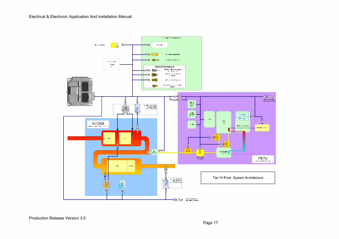
2.2 Aftertreatment System Sensor & Actuator Details
2.2.1 PM Capture Devices
The Tier 4 Final product range use both in cylinder PM (Particulate Matter) reduction methods and additional PM capture (DPF) exhaust system components. For low power 1204F ratings all PM management is made in cylinder removing the need for an engine DPF. Ratings above 110kW are supplied with a Diesel Particulate Filter (along with a DOC & SCR system) to meet the Tier 4 Final PM reduction targets. All Diesel Particulate Filter technology used by the 1204F to 1206F product range uses Low Temperature regeneration methods to remove the soot build up within the filter.
2.2.3 Selective Catalytic Reduction (SCR) Technologies
The SCR system supplied by Perkins with each Tier 4 Final engine family differs depending on the selected product. In principle however the 1204F and 1206F DEF systems are made up of the same core components as listed below;
• DEF Tank and Header Unit. The Header controls feed of DEF out to the DEF pump and houses temperature and level sensors. Unit also provides mechanism for tank thaw to be achieved during engine running.
• Coolant Valve. Controls the flow of engine coolant out to the DEF header to aid DEF thaw.
• DEF Heated Lines. Required to supply DEF to and from the DEF pump and from the DEF pump out to the DEF injector. Each line has a heated element electrical connection to ensure DEF flowing through the lines is kept form freezing.
• Dosing Control Unit. The SCR system DCU controller is required to provide localised control of the aftertreatment DEF system and manage the system communication between the SCR system and the engine ECM.
• DEF Pump Unit. The DEF pump unit is required to draw DEF from the tank and provide pressurised fluid to the DEF injector. The DEF pump is also responsible for purging the system of DEF during engine shutdown.
• DEF Injector. The DEF injector is responsible for dispersing DEF into the engine exhaust Post DOC / DPF to provide DEF storage across the SCR catalyst.
• SCR (Selective Catalytic Reduction) Catalyst. Used to store DEF (Urea) across a catalyst material so that when engine exhaust gas is passed over it NOx gas is removed.
Electrical & Electronic Application And Installation Manual
Production Release Version 3.0 Page 13
2.3 System Component Diagrams & Schematics
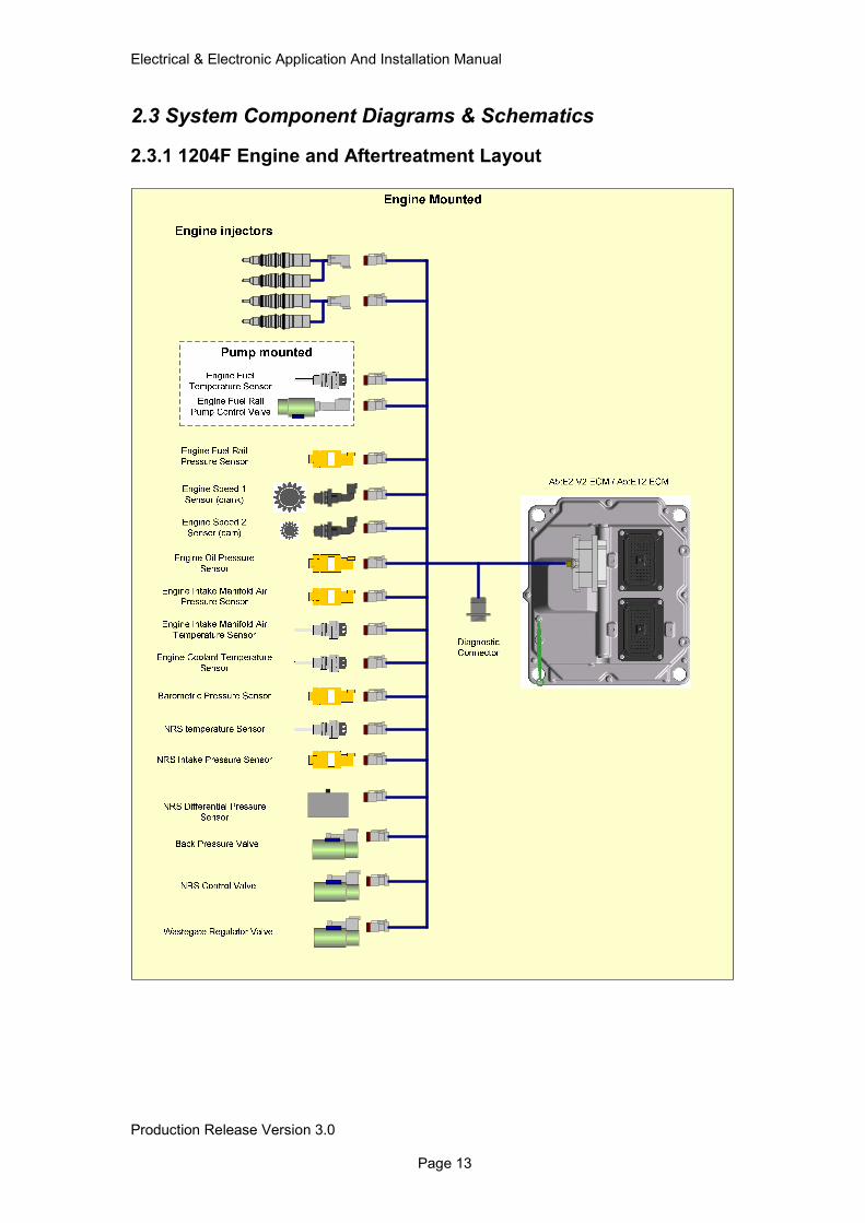
2.3.1 1204F Engine and Aftertreatment Layout
Electrical & Electronic Application And Installation Manual
Production Release Version 3.0 Page 14
NO
x
NO
x
A1:E
1
IGC
EM
ID
Electrical & Electronic Application And Installation Manual
Production Release Version 3.0 Page 15
Electrical & Electronic Application And Installation Manual
Production Release Version 3.0 Page 16
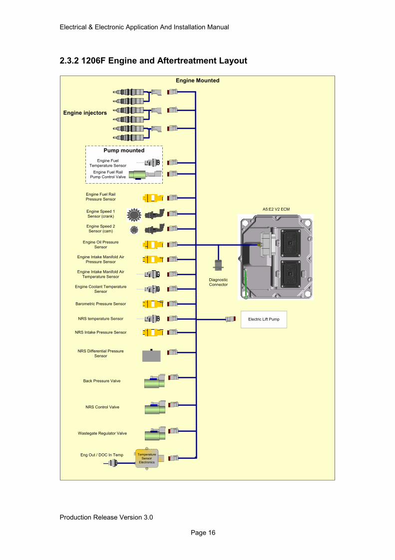
2.3.2 1206F Engine and Aftertreatment Layout
Engine Mounted
Engine injectors
Pump mounted
Engine Fuel
Temperature Sensor
Engine Fuel Rail
Pump Control Valve
Engine Fuel Rail
Pressure Sensor
Engine Speed 1
Sensor (crank)
Engine Speed 2
Sensor (cam)
Engine Oil Pressure
Sensor
Engine Intake Manifold Air
Pressure Sensor
Engine Intake Manifold Air
Temperature Sensor
Engine Coolant Temperature
Sensor
Barometric Pressure Sensor
NRS Control Valve
Wastegate Regulator Valve
Back Pressure Valve
NRS Intake Pressure Sensor
NRS temperature Sensor
NRS Differential Pressure
Sensor
Diagnostic
Connector
Electric Lift Pump
Temperature
Sensor
Electronics
Eng Out / DOC In Temp
A5:E2 V2 ECM
Electrical & Electronic Application And Installation Manual
Production Release Version 3.0 Page 17
Te
mp
era
ture
Se
nso
r
Ele
ctr
on
ics
A1
:E1
IGC
EM
ID
NO
x
NO
x
DE
F
Hea
ter
DE
F
Heate
r
Electrical & Electronic Application And Installation Manual
Production Release Version 3.0 Page 18
2.4 Engine & Aftertreatment Component Layout Diagrams
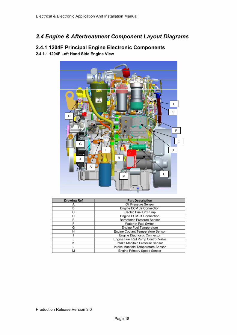
2.4.1 1204F Principal Engine Electronic Components 2.4.1.1 1204F Left Hand Side Engine View
Drawing Ref Part Description
A Oil Pressure Sensor
B Engine ECM J2 Connection
C Electric Fuel Lift Pump
D Engine ECM J1 Connection
E Barometric Pressure Sensor
F Water In Fuel Switch
G Engine Fuel Temperature
H Engine Coolant Temperature Sensor
I Engine Diagnostic Connector
J Engine Fuel Rail Pump Control Valve
K Intake Manifold Pressure Sensor
L Intake Manifold Temperature Sensor
M Engine Primary Speed Sensor
A
B
C
D
E
F
G
H
I
J
K
L
M
Electrical & Electronic Application And Installation Manual
Production Release Version 3.0 Page 19
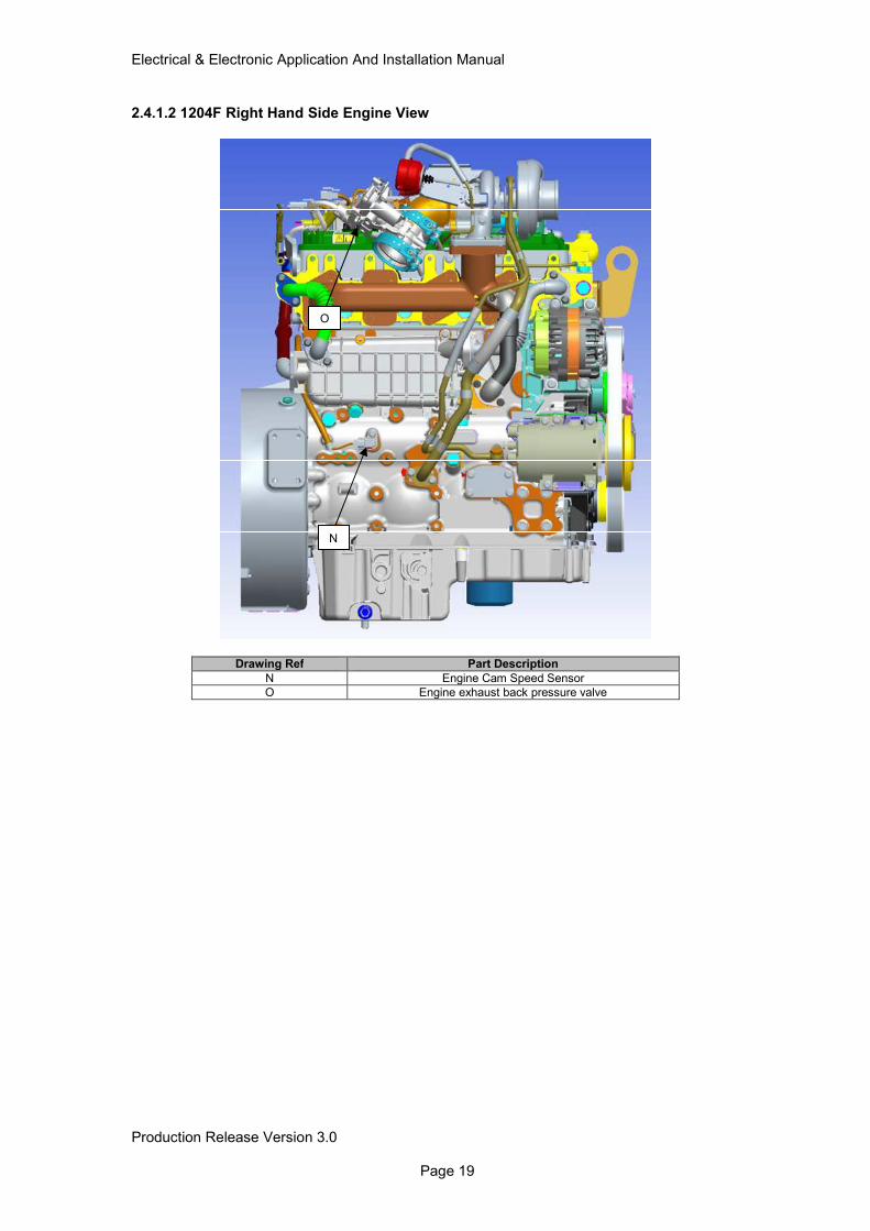
2.4.1.2 1204F Right Hand Side Engine View
Drawing Ref Part Description
N Engine Cam Speed Sensor
O Engine exhaust back pressure valve
N
O
Electrical & Electronic Application And Installation Manual
Production Release Version 3.0 Page 20
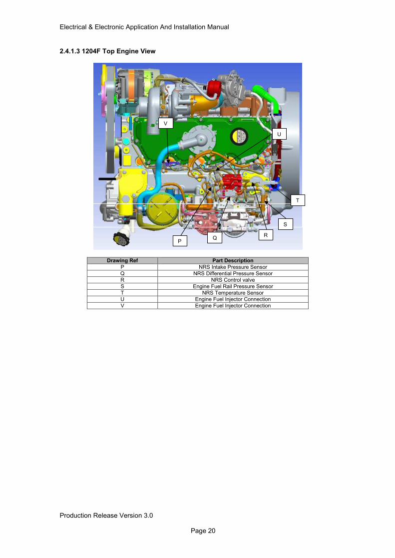
2.4.1.3 1204F Top Engine View
Drawing Ref Part Description
P NRS Intake Pressure Sensor
Q NRS Differential Pressure Sensor
R NRS Control valve
S Engine Fuel Rail Pressure Sensor
T NRS Temperature Sensor
U Engine Fuel Injector Connection
V Engine Fuel Injector Connection
Q P
R
S
U
V
T
Electrical & Electronic Application And Installation Manual
Production Release Version 3.0 Page 21
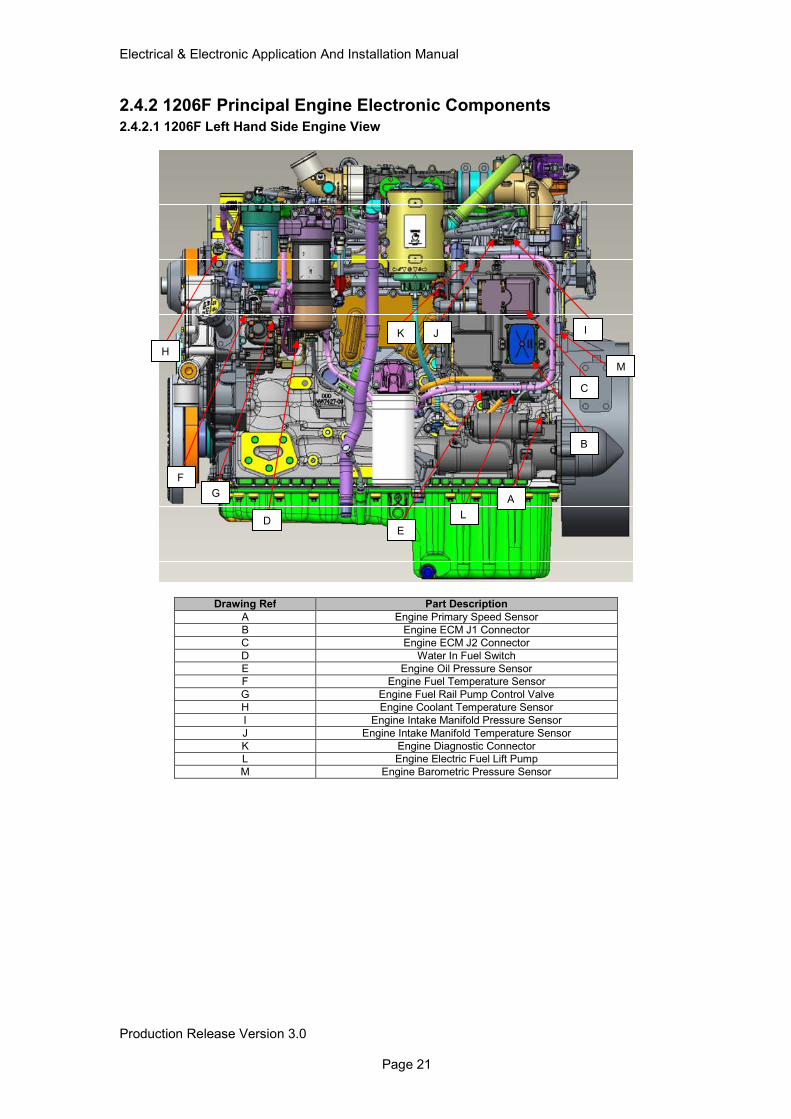
2.4.2 1206F Principal Engine Electronic Components 2.4.2.1 1206F Left Hand Side Engine View
Drawing Ref Part Description
A Engine Primary Speed Sensor
B Engine ECM J1 Connector
C Engine ECM J2 Connector
D Water In Fuel Switch
E Engine Oil Pressure Sensor
F Engine Fuel Temperature Sensor
G Engine Fuel Rail Pump Control Valve
H Engine Coolant Temperature Sensor
I Engine Intake Manifold Pressure Sensor
J Engine Intake Manifold Temperature Sensor
K Engine Diagnostic Connector
L Engine Electric Fuel Lift Pump
M Engine Barometric Pressure Sensor
B
C
D
A
E
F
G
H
I J K
L
M
Electrical & Electronic Application And Installation Manual
Production Release Version 3.0 Page 22
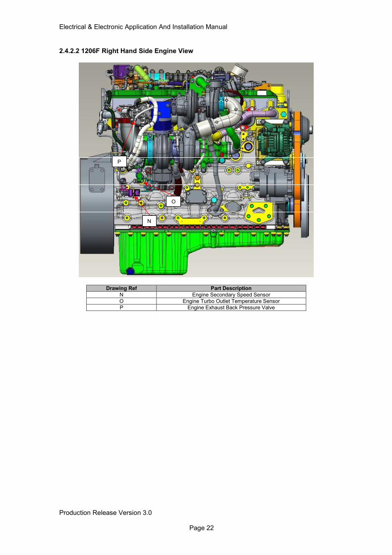
2.4.2.2 1206F Right Hand Side Engine View
Drawing Ref Part Description
N Engine Secondary Speed Sensor
O Engine Turbo Outlet Temperature Sensor
P Engine Exhaust Back Pressure Valve
N
O
P
Electrical & Electronic Application And Installation Manual
Production Release Version 3.0 Page 23
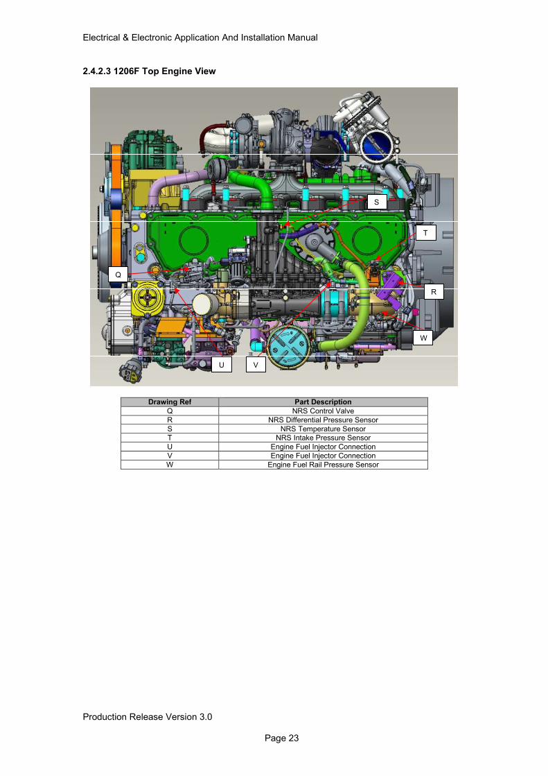
2.4.2.3 1206F Top Engine View
Drawing Ref Part Description
Q NRS Control Valve
R NRS Differential Pressure Sensor
S NRS Temperature Sensor
T NRS Intake Pressure Sensor
U Engine Fuel Injector Connection
V Engine Fuel Injector Connection
W Engine Fuel Rail Pressure Sensor
Q
R
S
T
U V
W
Electrical & Electronic Application And Installation Manual
Production Release Version 3.0 Page 24
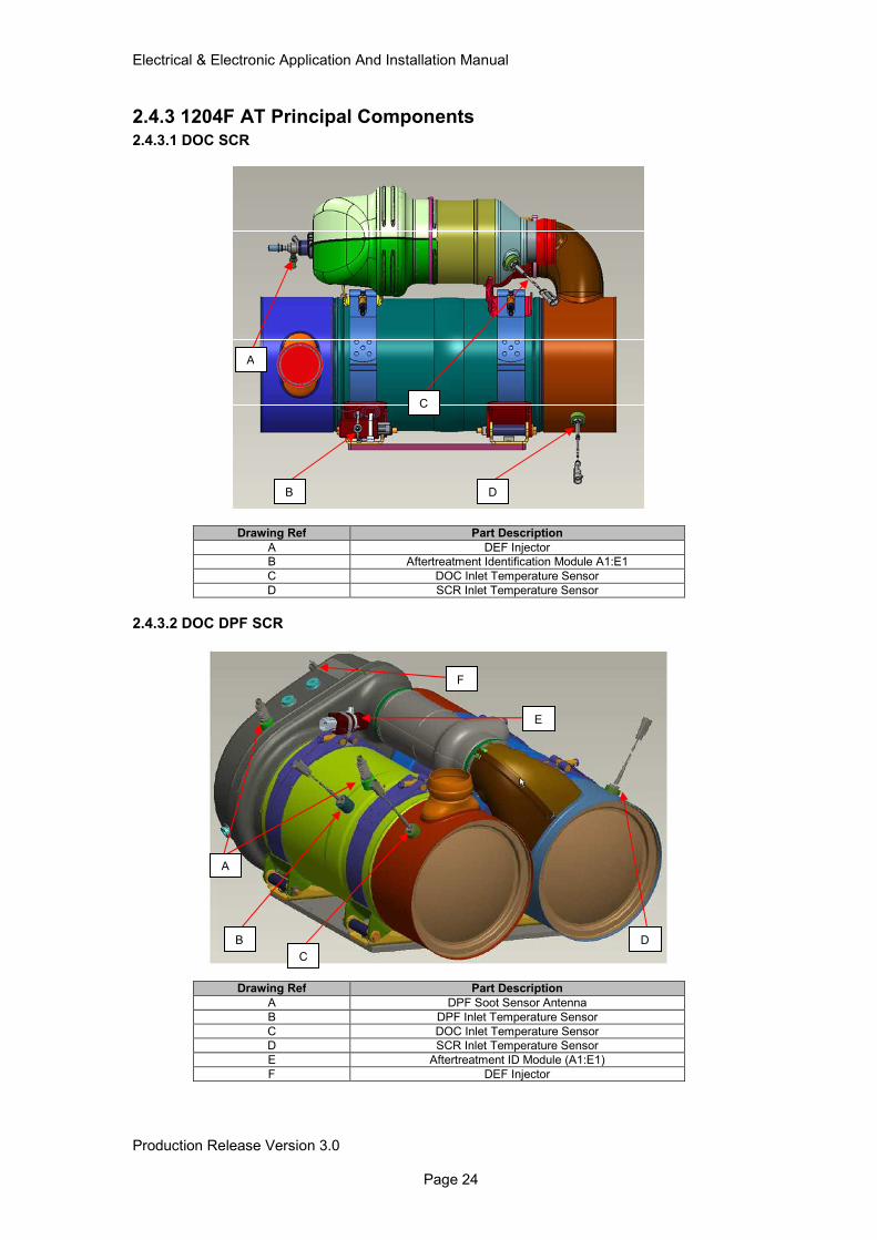
2.4.3 1204F AT Principal Components 2.4.3.1 DOC SCR
Drawing Ref Part Description
A DEF Injector
B Aftertreatment Identification Module A1:E1
C DOC Inlet Temperature Sensor
D SCR Inlet Temperature Sensor
2.4.3.2 DOC DPF SCR
Drawing Ref Part Description
A DPF Soot Sensor Antenna
B DPF Inlet Temperature Sensor
C DOC Inlet Temperature Sensor
D SCR Inlet Temperature Sensor
E Aftertreatment ID Module (A1:E1)
F DEF Injector
C
B
A
E
D
F
D
C
B
A
Electrical & Electronic Application And Installation Manual
Production Release Version 3.0 Page 25
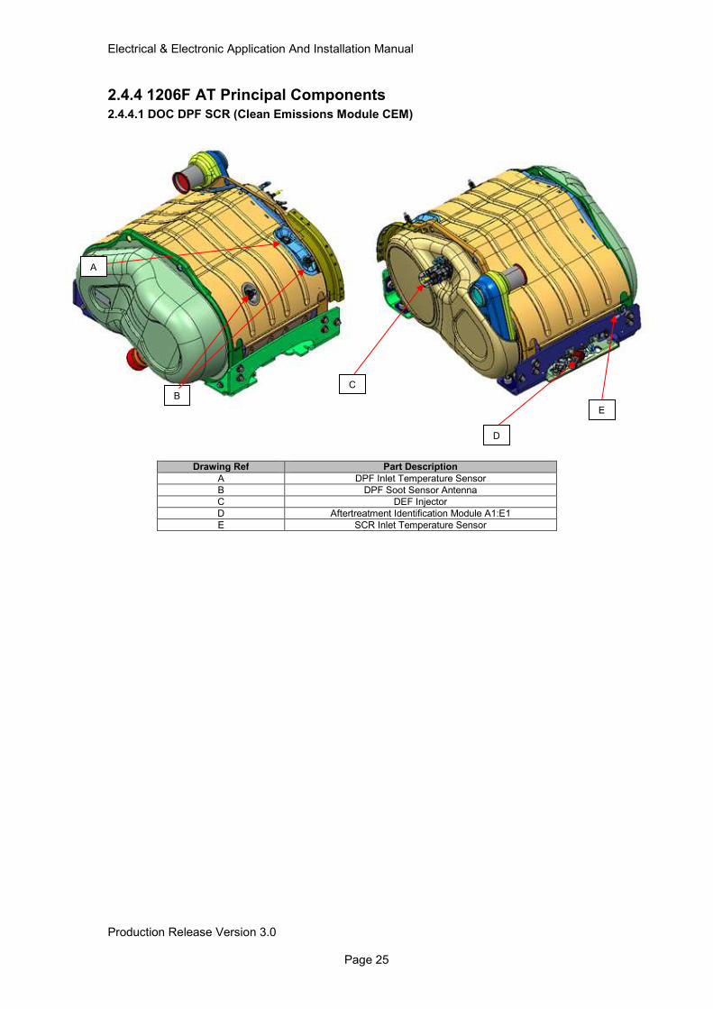
2.4.4 1206F AT Principal Components 2.4.4.1 DOC DPF SCR (Clean Emissions Module CEM)
Drawing Ref Part Description
A DPF Inlet Temperature Sensor
B DPF Soot Sensor Antenna
C DEF Injector
D Aftertreatment Identification Module A1:E1
E SCR Inlet Temperature Sensor
B C
E
A
D
Electrical & Electronic Application And Installation Manual
Production Release Version 3.0 Page 26
3.0 Customer System Overview Key Elements The following section provides details on both the mandatory and optional system connections that need to be made as part of the customers machine wiring harness.
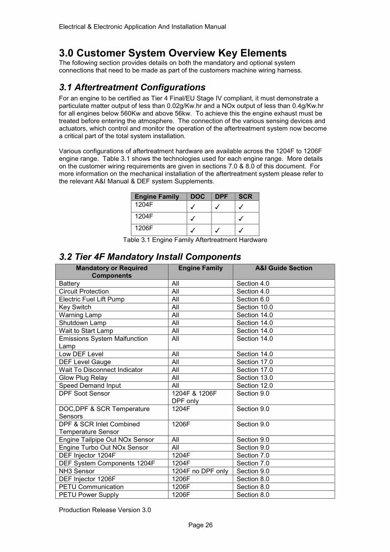
3.1 Aftertreatment Configurations For an engine to be certified as Tier 4 Final/EU Stage IV compliant, it must demonstrate a particulate matter output of less than 0.02g/Kw.hr and a NOx output of less than 0.4g/Kw.hr for all engines below 560Kw and above 56kw. To achieve this the engine exhaust must be treated before entering the atmosphere. The connection of the various sensing devices and actuators, which control and monitor the operation of the aftertreatment system now become a critical part of the total system installation. Various configurations of aftertreatment hardware are available across the 1204F to 1206F engine range. Table 3.1 shows the technologies used for each engine range. More details on the customer wiring requirements are given in sections 7.0 & 8.0 of this document. For more information on the mechanical installation of the aftertreatment system please refer to the relevant A&I Manual & DEF system Supplements.
Engine Family DOC DPF SCR
1204F
1204F 1206F
Table 3.1 Engine Family Aftertreatment Hardware
3.2 Tier 4F Mandatory Install Components Mandatory or Required
Components Engine Family A&I Guide Section
Battery All Section 4.0
Circuit Protection All Section 4.0
Electric Fuel Lift Pump All Section 6.0
Key Switch All Section 10.0
Warning Lamp All Section 14.0
Shutdown Lamp All Section 14.0
Wait to Start Lamp All Section 14.0
Emissions System Malfunction Lamp
All Section 14.0
Low DEF Level All Section 14.0
DEF Level Gauge All Section 17.0
Wait To Disconnect Indicator All Section 17.0
Glow Plug Relay All Section 13.0
Speed Demand Input All Section 12.0
DPF Soot Sensor 1204F & 1206F DPF only
Section 9.0
DOC,DPF & SCR Temperature Sensors
1204F Section 9.0
DPF & SCR Inlet Combined Temperature Sensor
1206F Section 9.0
Engine Tailpipe Out NOx Sensor All Section 9.0
Engine Turbo Out NOx Sensor All Section 9.0
DEF Injector 1204F 1204F Section 7.0
DEF System Components 1204F 1204F Section 7.0
NH3 Sensor 1204F no DPF only Section 9.0
DEF Injector 1206F 1206F Section 8.0
PETU Communication 1206F Section 8.0
PETU Power Supply 1206F Section 8.0
Electrical & Electronic Application And Installation Manual
Production Release Version 3.0 Page 27
IG CEM ID Module 1206F Section 9.0
Water in Fuel Sensor All Section 6.0
Air Inlet Temperature Sensor All Section 6.0
3.3 Optional Customer Installed Components Optional Components A&I Guide Section
Low Oil Pressure Lamp Section 14.0
Remote Shutdown Switch (Normally Open) Section 10.0
Coolant Level Switch Section 16.0
Air Filter Restriction (Inlet Depression) Switch / Sensor
Section 16.0
PWM Throttle Position Sensor Section 12.0
Analogue Throttle Position Sensor with Idle Validation Switch (1)
Section 12.0
Analogue Throttle Position Sensor with Idle Validation Switch (2)
Section 12.0
Throttle Arbitration Switch Section 12.0
Multi-Position Switch Section 12.0
PTO On/Off Switch Section 12.0
PTO Set/Lower Switch Section 12.0
PTO Raise/Resume Switch Section 12.0
PTO Speed Select Switch Section 12.0
PTO Disengage Switch Section 12.0
Mode Switch (1) Section 17.0
Mode Switch (2) Section 17.0
Intermediate Engine Speed Switch Section 12.0
Ether Start Section 13.0
Auxiliary Temperature Section 16.0
Auxiliary Pressure Section 16.0
Aftertreatment Ambient Air Temperature Section 13.0
Overspeed Verify Switch Section 10.0
Electrical & Electronic Application And Installation Manual
Production Release Version 3.0 Page 28
4.0 Power & Grounding Considerations
4.1 System Grounding Although the engine electronics are all directly grounded via the ECM connector, it is also necessary to ensure that the engine block is properly grounded, to provide a good return path for components such as the starter motor, alternator and cold start aids. Improper grounding results in unreliable electrical circuit paths. Stray electrical currents can damage mechanical components and make electronic systems prone to interference. These problems are often very difficult to diagnose and repair.
4.1.1 Ground Stud On Starter Motor
If the Starter motor has a grounding stud then this should be used. The ground connection should be made directly back to the battery negative terminal. The starter motor ground path must not include any flanges or joints. Painted surfaces and flexible mounts in particular must be avoided. Star washers must not be relied upon to make contact though paint. The ground cable should be of sufficient cross sectional area to ensure that the total starter motor supply circuit resistance does not exceed 1.7mOhms for a 12V system and 3.4mOhm for a 24V system. Please refer to the Starting and Charging Systems Manual for further information on starter motor, alternator, battery and complete system installation guidelines.
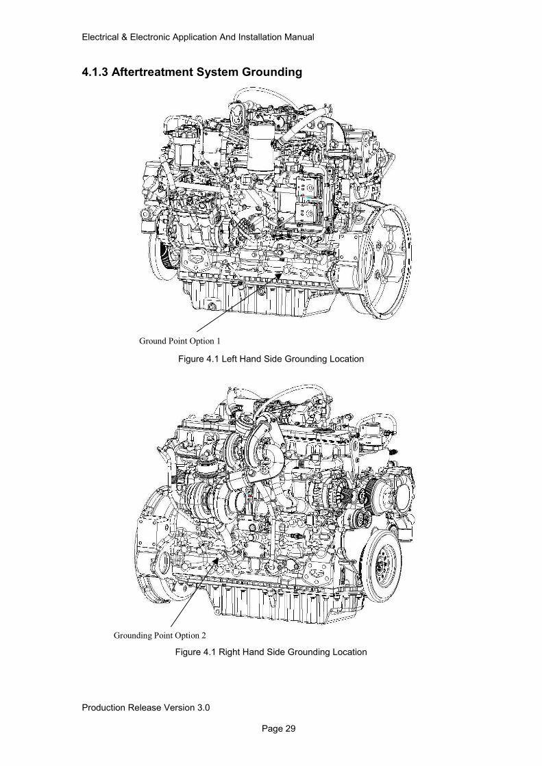
4.1.2 Engine Block Ground Connection A separate engine block ground should be used in addition to the starter motor ground. A ground cable direct from the battery negative or starter ground terminal should be connected to a ring terminal, which connects to one of the two tapping’s shown in figures 4.1 and 4.2. The tapped holes will be reserved for customer use and can be used for grounding purposes. If a tapping is used it should be checked to ensure it is free from lacquer, paint and dirt before the connection is made. An M10 metric screw plated with zinc should be used. A washer should retain the ring terminal and the screw tightened to 44Nm (32 lb-ft).
Electrical & Electronic Application And Installation Manual
Production Release Version 3.0 Page 29
4.1.3 Aftertreatment System Grounding
Figure 4.1 Left Hand Side Grounding Location
Figure 4.1 Right Hand Side Grounding Location
Ground Point Option 1
Grounding Point Option 2
Electrical & Electronic Application And Installation Manual
Production Release Version 3.0 Page 30
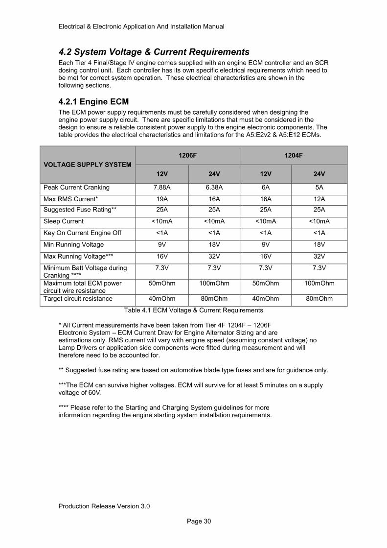
4.2 System Voltage & Current Requirements Each Tier 4 Final/Stage IV engine comes supplied with an engine ECM controller and an SCR dosing control unit. Each controller has its own specific electrical requirements which need to be met for correct system operation. These electrical characteristics are shown in the following sections.
4.2.1 Engine ECM
The ECM power supply requirements must be carefully considered when designing the engine power supply circuit. There are specific limitations that must be considered in the design to ensure a reliable consistent power supply to the engine electronic components. The table provides the electrical characteristics and limitations for the A5:E2v2 & A5:E12 ECMs.
VOLTAGE SUPPLY SYSTEM
1206F 1204F
12V 24V 12V 24V
Peak Current Cranking 7.88A 6.38A 6A 5A
Max RMS Current* 19A 16A 16A 12A
Suggested Fuse Rating** 25A 25A 25A 25A
Sleep Current <10mA <10mA <10mA <10mA
Key On Current Engine Off <1A <1A <1A <1A
Min Running Voltage 9V 18V 9V 18V
Max Running Voltage*** 16V 32V 16V 32V
Minimum Batt Voltage during Cranking ****
7.3V 7.3V 7.3V 7.3V
Maximum total ECM power circuit wire resistance
50mOhm 100mOhm 50mOhm 100mOhm
Target circuit resistance 40mOhm 80mOhm 40mOhm 80mOhm
Table 4.1 ECM Voltage & Current Requirements * All Current measurements have been taken from Tier 4F 1204F – 1206F Electronic System – ECM Current Draw for Engine Alternator Sizing and are estimations only. RMS current will vary with engine speed (assuming constant voltage) no Lamp Drivers or application side components were fitted during measurement and will therefore need to be accounted for. ** Suggested fuse rating are based on automotive blade type fuses and are for guidance only. ***The ECM can survive higher voltages. ECM will survive for at least 5 minutes on a supply voltage of 60V. **** Please refer to the Starting and Charging System guidelines for more information regarding the engine starting system installation requirements.
Electrical & Electronic Application And Installation Manual
Production Release Version 3.0 Page 31
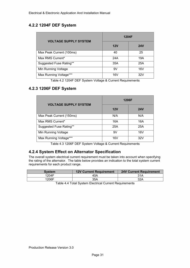
4.2.2 1204F DEF System
VOLTAGE SUPPLY SYSTEM
1204F
12V 24V
Max Peak Current (100ms) 40 25
Max RMS Current* 24A 19A
Suggested Fuse Rating** 35A 25A
Min Running Voltage 9V 16V
Max Running Voltage*** 16V 32V
Table 4.2 1204F DEF System Voltage & Current Requirements
4.2.3 1206F DEF System
VOLTAGE SUPPLY SYSTEM
1206F
12V 24V
Max Peak Current (150ms) N/A N/A
Max RMS Current* 16A 16A
Suggested Fuse Rating** 25A 25A
Min Running Voltage 9V 16V
Max Running Voltage*** 16V 32V
Table 4.3 1206F DEF System Voltage & Current Requirements
4.2.4 System Effect on Alternator Specification
The overall system electrical current requirement must be taken into account when specifying the rating of the alternator. The table below provides an indication to the total system current requirements for each product range.
System 12V Current Requirement 24V Current Requirement
1204F 40A 31A
1206F 35A 32A
Table 4.4 Total System Electrical Current Requirements
Electrical & Electronic Application And Installation Manual
Production Release Version 3.0 Page 32
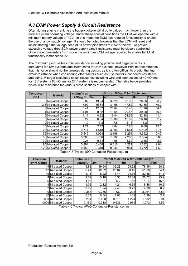
4.3 ECM Power Supply & Circuit Resistance Often during engine cranking the battery voltage will drop to values much lower than the normal system operating voltage. Under these special conditions the ECM will operate with a minimum battery voltage of 7.3V. In this mode the ECM has reduced functionality to enable the use of a low supply voltage. It should be noted however that the ECM will reset and inhibit starting if the voltage seen at its power pins drops to 5.5V or below. To prevent excessive voltage drop ECM power supply circuit resistance must be closely controlled. Once the engine enters ‘run’ mode the minimum ECM voltage required to enable full ECM functionality increases to 9V. The maximum permissible circuit resistance including positive and negative wires is 50mOhms for 12V systems and 100mOhms for 24V systems, however Perkins recommends that this value should not be targeted during design, as it is often difficult to predict the final circuit resistance when considering other factors such as fuse holders, connector resistance and aging. A target calculated circuit resistance including wire and connections of 40mOhms for 12V systems 80mOhms for 24V systems is recommended. The table below provides typical wire resistance for various cross sections of copper wire.
Table 4.5 Typical ISO Conductor Resistance / m
Table 4.6 Typical AWG Conductor Resistance / m
2m 4m 6m 8m 10m
2 Ni-plated Copper 9.82 19.64 39.28 58.92 78.56 98.2
2.5 Ni-plated Copper 7.92 15.84 31.68 47.52 63.36 79.2
3 Ni-plated Copper 6.41 12.82 25.64 38.46 51.28 64.1
4 Ni-plated Copper 4.91 9.82 19.64 29.46 39.28 49.1
5 Ni-plated Copper 4.11 8.22 16.44 24.66 32.88 41.1
6 Ni-plated Copper 3.27 6.54 13.08 19.62 26.16 32.7
10 Ni-plated Copper 1.9 3.8 7.6 11.4 15.2 19
16 Ni-plated Copper 1.21 2.42 4.84 7.26 9.68 12.1
25 Ni-plated Copper 0.774 1.548 3.096 4.644 6.192 7.74
35 Ni-plated Copper 0.549 1.098 2.196 3.294 4.392 5.49
50 Ni-plated Copper 0.383 0.766 1.532 2.298 3.064 3.83
70 Ni-plated Copper 0.27 0.54 1.08 1.62 2.16 2.7
95 Ni-plated Copper 0.204 0.408 0.816 1.224 1.632 2.04
120 Ni-plated Copper 0.159 0.318 0.636 0.954 1.272 1.59
mohm/m at
20Deg CMaterial
Conductor
CSA
mOhm at 20Deg C for Cable Length
2m 4m 6m 8m 10m
14 Ni-plated Copper 9.82 19.64 39.28 58.92 78.56 98.2
12 Ni-plated Copper 6.41 12.82 25.64 38.46 51.28 64.1
10 Ni-plated Copper 4.11 8.22 16.44 24.66 32.88 41.1
8 Ni-plated Copper 2.59 5.18 10.36 15.54 20.72 25.9
6 Ni-plated Copper 1.55 3.1 6.2 9.3 12.4 15.5
4 Ni-plated Copper 1.06 2.12 4.24 6.36 8.48 10.6
2 Ni-plated Copper 0.62 1.24 2.48 3.72 4.96 6.2
0 Ni-plated Copper 0.383 0.766 1.532 2.298 3.064 3.83
00 Ni-plated Copper 0.27 0.54 1.08 1.62 2.16 2.7
000 Ni-plated Copper 0.204 0.408 0.816 1.224 1.632 2.04
0000 Ni-plated Copper 0.159 0.318 0.636 0.954 1.272 1.59
American
Wire GaugeMaterial
mohm/m at
20Deg C
mOhm at 20Deg C for Cable Length
Electrical & Electronic Application And Installation Manual
Production Release Version 3.0 Page 33
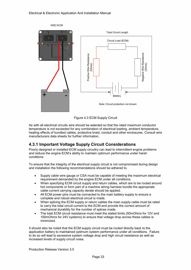
Figure 4.3 ECM Supply Circuit
As with all electrical circuits wire should be selected so that the rated maximum conductor temperature is not exceeded for any combination of electrical loading, ambient temperature, heating effects of bundled cables, protective braid, conduit and other enclosures. Consult wire manufacturers data sheets for further information.
4.3.1 Important Voltage Supply Circuit Considerations Poorly designed or installed ECM supply circuitry can lead to intermittent engine problems and reduce the engine ECM’s ability to maintain optimum performance under harsh conditions. To ensure that the integrity of the electrical supply circuit is not compromised during design and installation the following recommendations should be adhered to.
• Supply cable wire gauge or CSA must be capable of meeting the maximum electrical requirement demanded by the engine ECM under all conditions.
• When specifying ECM circuit supply and return cables, which are to be routed around hot components or form part of a machine wiring harness bundle the appropriate cable current carrying capacity derate should be applied.
• All ECM power pins must be connected to the main battery supply to ensure a complete and robust electrical circuit is made.
• When splicing the ECM supply or return cables the main supply cable must be rated to carry the total circuit current to the ECM and provide the correct amount of mechanical durability for the number of splices made.
• The total ECM circuit resistance must meet the stated limits (50mOhms for 12V and 100mOhms for 24V systems) to ensure that voltage drop across these cables is minimized.
It should also be noted that the ECM supply circuit must be routed directly back to the application battery to maintained optimum system performance under all conditions. Failure to do so will lead to excessive system voltage drop and high circuit resistance as well as increased levels of supply circuit noise.
A5E2 ECM
-+ Battery
Negative W
ire R
esis
tance
(Ohm
s)
Po
sitiv
e W
ire
Re
sis
tance
(Ohm
s)
Circuit Load (ECM)
Total Circuit Length
Note: Circuit protection not shown
Electrical & Electronic Application And Installation Manual
Production Release Version 3.0 Page 34
4.3.2 Battery (+) Connection
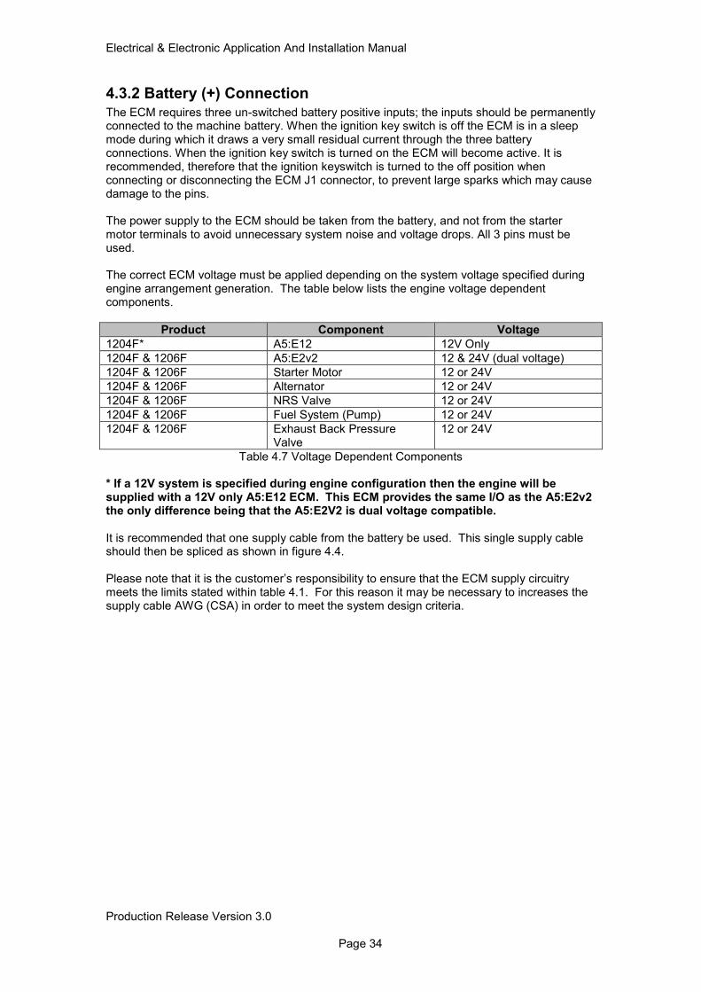
The ECM requires three un-switched battery positive inputs; the inputs should be permanently connected to the machine battery. When the ignition key switch is off the ECM is in a sleep mode during which it draws a very small residual current through the three battery connections. When the ignition key switch is turned on the ECM will become active. It is recommended, therefore that the ignition keyswitch is turned to the off position when connecting or disconnecting the ECM J1 connector, to prevent large sparks which may cause damage to the pins. The power supply to the ECM should be taken from the battery, and not from the starter motor terminals to avoid unnecessary system noise and voltage drops. All 3 pins must be used. The correct ECM voltage must be applied depending on the system voltage specified during engine arrangement generation. The table below lists the engine voltage dependent components.
Product Component Voltage
1204F* A5:E12 12V Only
1204F & 1206F A5:E2v2 12 & 24V (dual voltage)
1204F & 1206F Starter Motor 12 or 24V
1204F & 1206F Alternator 12 or 24V
1204F & 1206F NRS Valve 12 or 24V
1204F & 1206F Fuel System (Pump) 12 or 24V
1204F & 1206F Exhaust Back Pressure Valve
12 or 24V
Table 4.7 Voltage Dependent Components
* If a 12V system is specified during engine configuration then the engine will be supplied with a 12V only A5:E12 ECM. This ECM provides the same I/O as the A5:E2v2 the only difference being that the A5:E2V2 is dual voltage compatible. It is recommended that one supply cable from the battery be used. This single supply cable should then be spliced as shown in figure 4.4. Please note that it is the customer’s responsibility to ensure that the ECM supply circuitry meets the limits stated within table 4.1. For this reason it may be necessary to increases the supply cable AWG (CSA) in order to meet the system design criteria.
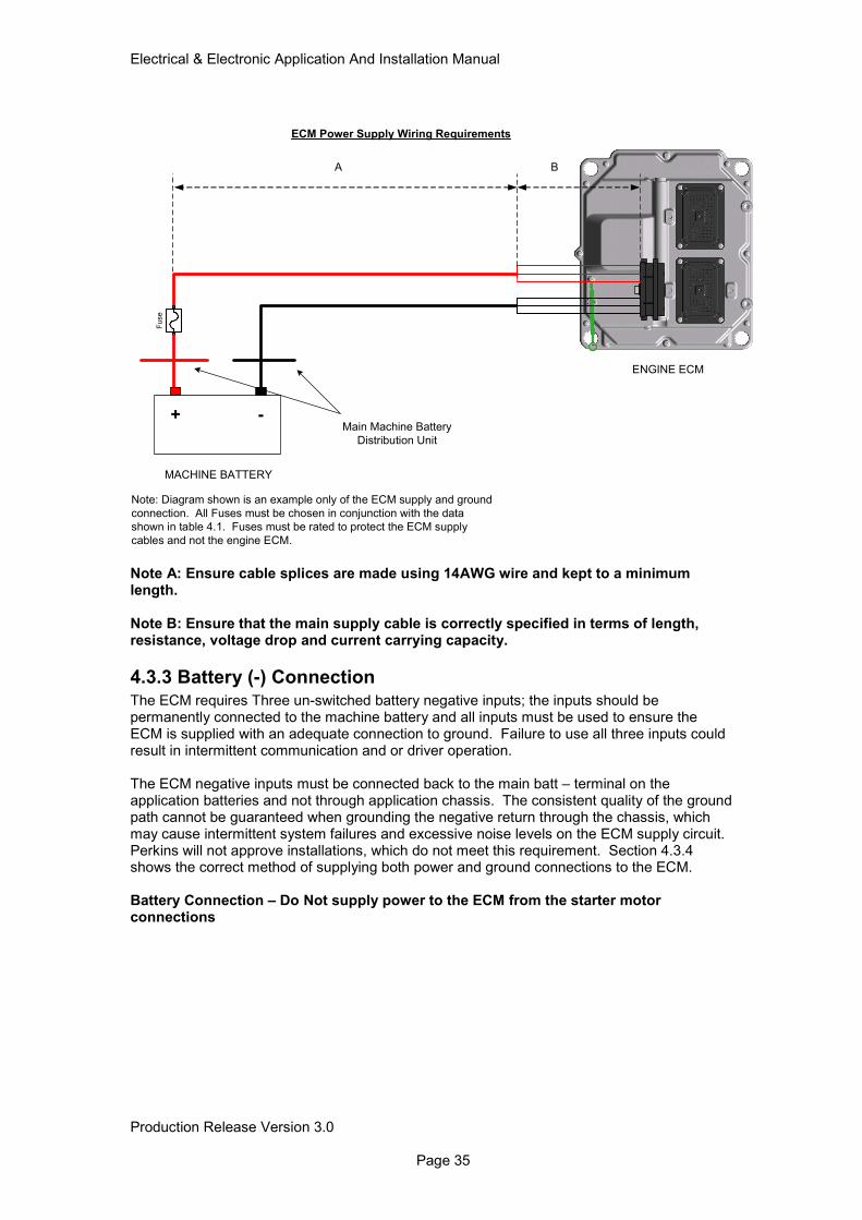
Electrical & Electronic Application And Installation Manual
Production Release Version 3.0 Page 35
Note A: Ensure cable splices are made using 14AWG wire and kept to a minimum length. Note B: Ensure that the main supply cable is correctly specified in terms of length, resistance, voltage drop and current carrying capacity.
4.3.3 Battery (-) Connection The ECM requires Three un-switched battery negative inputs; the inputs should be permanently connected to the machine battery and all inputs must be used to ensure the ECM is supplied with an adequate connection to ground. Failure to use all three inputs could result in intermittent communication and or driver operation. The ECM negative inputs must be connected back to the main batt – terminal on the application batteries and not through application chassis. The consistent quality of the ground path cannot be guaranteed when grounding the negative return through the chassis, which may cause intermittent system failures and excessive noise levels on the ECM supply circuit. Perkins will not approve installations, which do not meet this requirement. Section 4.3.4 shows the correct method of supplying both power and ground connections to the ECM. Battery Connection – Do Not supply power to the ECM from the starter motor connections
+ -
BA
MACHINE BATTERY
ENGINE ECM
Fuse
Main Machine Battery
Distribution Unit
Note: Diagram shown is an example only of the ECM supply and ground
connection. All Fuses must be chosen in conjunction with the data
shown in table 4.1. Fuses must be rated to protect the ECM supply
cables and not the engine ECM.
ECM Power Supply Wiring Requirements
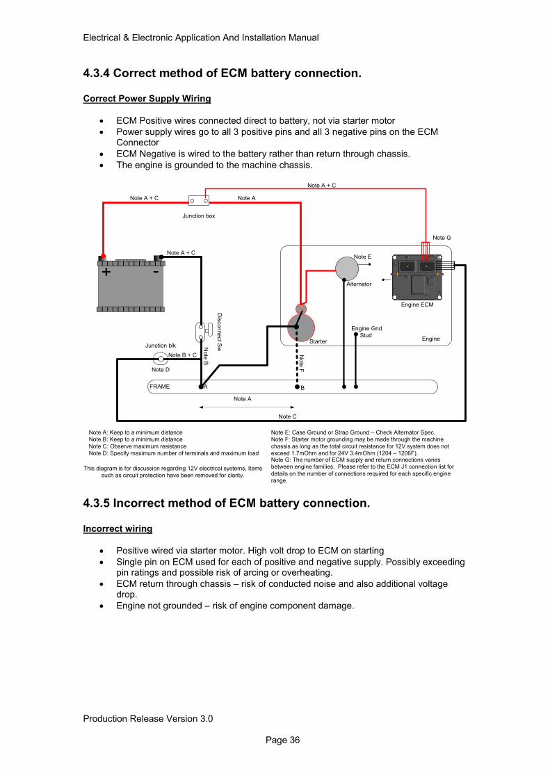
Electrical & Electronic Application And Installation Manual
Production Release Version 3.0 Page 36
4.3.4 Correct method of ECM battery connection.
Correct Power Supply Wiring
• ECM Positive wires connected direct to battery, not via starter motor
• Power supply wires go to all 3 positive pins and all 3 negative pins on the ECM Connector
• ECM Negative is wired to the battery rather than return through chassis.
• The engine is grounded to the machine chassis.
This diagram is for discussion regarding 12V electrical systems, Items
such as circuit protection have been removed for clarity.
-+
FRAME
Engine
Junction box
Starter
Alternator
Dis
con
ne
ct S
w
Engine ECM
Engine Gnd
Stud
Note A: Keep to a minimum distance
Note B: Keep to a minimum distance
Note C: Observe maximum resistance
Note D: Specify maximum number of terminals and maximum load
Note A + C
Note A + C
Note C
Note A + C
Note B + C
No
te B
Note D
Junction blk
A B
Note A
Note E: Case Ground or Strap Ground – Check Alternator Spec.
Note F: Starter motor grounding may be made through the machine
chassis as long as the total circuit resistance for 12V system does not
exceed 1.7mOhm and for 24V 3.4mOhm (1204 – 1206F).
No
te F
Note A
Note E
Note G: The number of ECM supply and return connections varies
between engine families. Please refer to the ECM J1 connection list for
details on the number of connections required for each specific engine
range.
Note G
4.3.5 Incorrect method of ECM battery connection.
Incorrect wiring
• Positive wired via starter motor. High volt drop to ECM on starting
• Single pin on ECM used for each of positive and negative supply. Possibly exceeding pin ratings and possible risk of arcing or overheating.
• ECM return through chassis – risk of conducted noise and also additional voltage drop.
• Engine not grounded – risk of engine component damage.
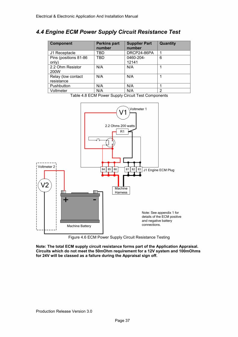
Electrical & Electronic Application And Installation Manual
Production Release Version 3.0 Page 37
4.4 Engine ECM Power Supply Circuit Resistance Test
Component Perkins part number
Supplier Part number
Quantity
J1 Receptacle TBD DRCP24-86PA 1
Pins (positions 81-86 only)
TBD 0460-204-12141
6
2.2 Ohm Resistor 200W
N/A N/A 1
Relay (low contact resistance
N/A N/A 1
Pushbutton N/A N/A 1
Voltmeter N/A N/A 2
Table 4.8 ECM Power Supply Circuit Test Components
R1
V1
2.2 Ohms 200 watts
Voltmeter 1
8684 85 81 82 83 J1 Engine ECM Plug
Machine
Harness
-+
V2
Voltmeter 2
Machine Battery
Note: See appendix 1 for details of the ECM positive
and negative battery connections.
Figure 4.6 ECM Power Supply Circuit Resistance Testing
Note: The total ECM supply circuit resistance forms part of the Application Appraisal. Circuits which do not meet the 50mOhm requirement for a 12V system and 100mOhms for 24V will be classed as a failure during the Appraisal sign off.
Electrical & Electronic Application And Installation Manual
Production Release Version 3.0 Page 38
4.4.1 Test Procedure
Record the measured resistance value of the test resistor used. Disconnect the J1 engine ECM plug from the ECM and connect the test apparatus as shown in figure 4.6. Press the button for three seconds and at the same time record the voltage measured from Voltmeter 1 and Voltmeter 2. Formula: Power Supply Circuit Resistance (mOhms) = 1000 * (R1 * (V2 – V1)/ V1) V1 = Voltmeter 1 Measured Value V2 = Voltmeter 2 Measured Value R1 = Measured Resistor Value Worked Example V1 = 11.8 V2 = 12 R1 = 2.21 Ohms 1000 * (2.21 * (12 – 11.8)/11.8) 1000 * (2.21 * 0.01695) 1000 * (0.0375) Harness Resistance = 37.5 mOhms
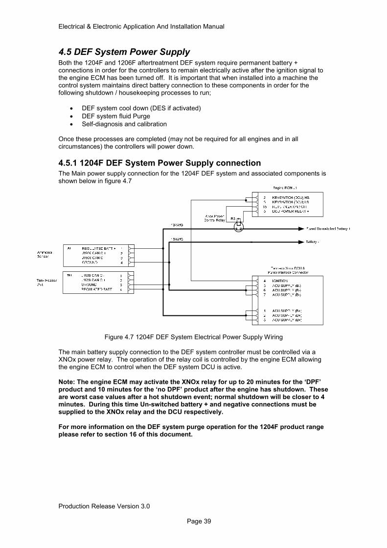
Electrical & Electronic Application And Installation Manual
Production Release Version 3.0 Page 39
4.5 DEF System Power Supply Both the 1204F and 1206F aftertreatment DEF system require permanent battery + connections in order for the controllers to remain electrically active after the ignition signal to the engine ECM has been turned off. It is important that when installed into a machine the control system maintains direct battery connection to these components in order for the following shutdown / housekeeping processes to run;
• DEF system cool down (DES if activated)
• DEF system fluid Purge
• Self-diagnosis and calibration Once these processes are completed (may not be required for all engines and in all circumstances) the controllers will power down.
4.5.1 1204F DEF System Power Supply connection The Main power supply connection for the 1204F DEF system and associated components is shown below in figure 4.7
Figure 4.7 1204F DEF System Electrical Power Supply Wiring
The main battery supply connection to the DEF system controller must be controlled via a XNOx power relay. The operation of the relay coil is controlled by the engine ECM allowing the engine ECM to control when the DEF system DCU is active. Note: The engine ECM may activate the XNOx relay for up to 20 minutes for the ‘DPF’ product and 10 minutes for the ‘no DPF’ product after the engine has shutdown. These are worst case values after a hot shutdown event; normal shutdown will be closer to 4 minutes. During this time Un-switched battery + and negative connections must be supplied to the XNOx relay and the DCU respectively. For more information on the DEF system purge operation for the 1204F product range please refer to section 16 of this document.
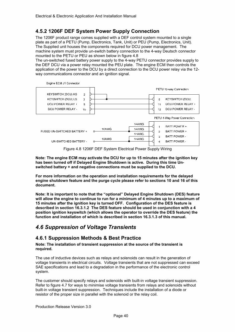
Electrical & Electronic Application And Installation Manual
Production Release Version 3.0 Page 40
4.5.2 1206F DEF System Power Supply Connection
The 1206F product range comes supplied with a DEF control system mounted to a single plate as part of a PETU (Pump, Electronics, Tank, Unit) or PEU (Pump, Electronics, Unit). The Supplied unit houses the components required for DCU power management. The machine system must provide un-switch battery connection to the 4-way Deutsch connector mounted to the PETU or PEU as shown below in figure 4.8 The un-switched fused battery power supply to the 4-way PETU connector provides supply to the DEF DCU via a power relay mounted the PEU plate. The engine ECM then controls the application of the power to the DCU by a direct connection to the DCU power relay via the 12-way communications connector and an ignition signal.
Figure 4.8 1206F DEF System Electrical Power Supply Wiring Note: The engine ECM may activate the DCU for up to 15 minutes after the ignition key has been turned off if Delayed Engine Shutdown is active. During this time Un-switched battery + and negative connections must be supplied to the DCU. For more information on the operation and installation requirements for the delayed engine shutdown feature and the purge cycle please refer to sections 10 and 16 of this document. Note: It is important to note that the “optional” Delayed Engine Shutdown (DES) feature will allow the engine to continue to run for a minimum of 4 minutes up to a maximum of 15 minutes after the ignition key is turned OFF. Configuration of the DES feature is described in section 16.3.1.2 The DES feature should be used in conjunction with a 4 position ignition keyswitch (which allows the operator to override the DES feature) the function and installation of which is described in section 16.3.1.3 of this manual.
4.6 Suppression of Voltage Transients
4.6.1 Suppression Methods & Best Practice Note: The installation of transient suppression at the source of the transient is required. The use of inductive devices such as relays and solenoids can result in the generation of voltage transients in electrical circuits. Voltage transients that are not suppressed can exceed SAE specifications and lead to a degradation in the performance of the electronic control system. The customer should specify relays and solenoids with built-in voltage transient suppression. Refer to figure 4.7 for ways to minimise voltage transients from relays and solenoids without built-in voltage transient suppression. Techniques include the installation of a diode or resistor of the proper size in parallel with the solenoid or the relay coil.
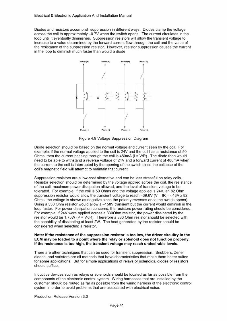
Electrical & Electronic Application And Installation Manual
Production Release Version 3.0 Page 41
Diodes and resistors accomplish suppression in different ways. Diodes clamp the voltage across the coil to approximately –0.7V when the switch opens. The current circulates in the loop until it eventually diminishes. Suppression resistors will allow the transient voltage to increase to a value determined by the forward current flow through the coil and the value of the resistance of the suppression resistor. However, resistor suppression causes the current in the loop to diminish much faster than would a diode.
Figure 4.9 Voltage Suppression Diagram
Diode selection should be based on the normal voltage and current seen by the coil. For example, if the normal voltage applied to the coil is 24V and the coil has a resistance of 50 Ohms, then the current passing through the coil is 480mA (I = V/R). The diode then would need to be able to withstand a reverse voltage of 24V and a forward current of 480mA when the current to the coil is interrupted by the opening of the switch since the collapse of the coil’s magnetic field will attempt to maintain that current. Suppression resistors are a low-cost alternative and can be less stressful on relay coils. Resistor selection should be determined by the voltage applied across the coil, the resistance of the coil, maximum power dissipation allowed, and the level of transient voltage to be tolerated. For example, if the coil is 50 Ohms and the voltage applied is 24V, an 82 Ohm suppression resistor would allow the transient voltage to reach –39.6V (V = IR = -.48A x 82 Ohms, the voltage is shown as negative since the polarity reverses once the switch opens). Using a 330 Ohm resistor would allow a –158V transient but the current would diminish in the loop faster. For power dissipation concerns, the resistors power rating should be considered. For example, if 24V were applied across a 330Ohm resistor, the power dissipated by the resistor would be 1.75W (P = V2/R). Therefore a 330 Ohm resistor should be selected with the capability of dissipating at least 2W. The heat generated by the resistor should be considered when selecting a resistor. Note: If the resistance of the suppression resistor is too low, the driver circuitry in the ECM may be loaded to a point where the relay or solenoid does not function properly. If the resistance is too high, the transient voltage may reach undesirable levels. There are other techniques that can be used for transient suppression. Snubbers, Zener diodes, and varistors are all methods that have characteristics that make them better suited for some applications. But for simple applications of relays or solenoids, diodes or resistors should suffice. Inductive devices such as relays or solenoids should be located as far as possible from the components of the electronic control system. Wiring harnesses that are installed by the customer should be routed as far as possible from the wiring harness of the electronic control system in order to avoid problems that are associated with electrical noise.
Electrical & Electronic Application And Installation Manual
Production Release Version 3.0 Page 42
4.7 Direct Battery connection requirements Some engine and aftertreatment components require direct fused battery connection to ensure they are allowed to go through a power down sequence after the engine ignition has been set to OFF. A list of the components requiring direct battery connection are shown below.
• Engine ECM
• Aftertreatment DCU
• Engine Fuel Lift Pump (via relay for 4 cyl only) The electrical power connection to these components must not be switched other than by a machine battery disconnect or emergency shutdown switch. Failure to meet this requirement may lead to engine and aftertreatment diagnostic code, shutdown procedure failures for example DEF system purge, Component failure and false tripping of engine diagnostics. The engine ECM will record and store engine shutdown events where the post ignition OFF process has been unable to run.
4.8 Powering The Engine ECM Via Auxiliary Power Supplies If the engine is to be supplied with electrical power via any other means than a standard machine battery arrangement, care must be taken when choosing the power supply. Engine ECM’s powered by devices such as switch mode power supplies can be particularly troublesome due to the intermittent high current load demands of the engine ECM during engine operation. To ensure that the power supply operates correctly, management of these intermittent high current spikes is employed.
4.9 Sensor Common Connections Certain components that interface directly with the ECM require connection to one of the dedicated sensor/switch return pins on the ECM customer machine interface connector J1. Separate sensor/switch returns are provided for analogue and digital signals. All components requiring connection to one of the ECM ground connections must be connected to the correct ground path to ensure the correct operation of the component.
4.9.1 Actuator Driver Return All of the following features must be connected back to the engine ECM J1 Actuator Driver return pins 15 & 49.
ECM Feature J1 Pin Location
Ether Start Solenoid 9
Glow Plug Relay 8
Engine Fuel Lift Pump relay 7
Table 4.9 Engine Actuator Connections
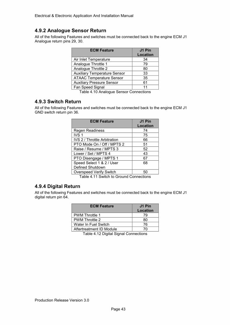
Electrical & Electronic Application And Installation Manual
Production Release Version 3.0 Page 43
4.9.2 Analogue Sensor Return
All of the following Features and switches must be connected back to the engine ECM J1 Analogue return pins 29, 30.
ECM Feature J1 Pin Location
Air Inlet Temperature 34
Analogue Throttle 1 79
Analogue Throttle 2 80
Auxiliary Temperature Sensor 33
ATAAC Temperature Sensor 35
Auxiliary Pressure Sensor 61
Fan Speed Signal 11
Table 4.10 Analogue Sensor Connections
4.9.3 Switch Return All of the following Features and switches must be connected back to the engine ECM J1 GND switch return pin 36.
ECM Feature J1 Pin Location
Regen Readiness 74
IVS 1 75
IVS 2 / Throttle Arbitration 66
PTO Mode On / Off / MPTS 2 51
Raise / Resume / MPTS 3 52
Lower / Set / MPTS 4 43
PTO Disengage / MPTS 1 67
Speed Select 1 & 2 / User Defined Shutdown
68
Overspeed Verify Switch 50
Table 4.11 Switch to Ground Connections
4.9.4 Digital Return
All of the following Features and switches must be connected back to the engine ECM J1 digital return pin 64.
ECM Feature J1 Pin Location
PWM Throttle 1 79
PWM Throttle 2 80
Water In Fuel Switch 76
Aftertreatment ID Module 70
Table 4.12 Digital Signal Connections
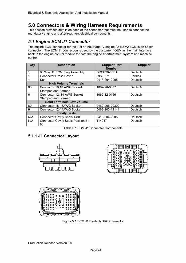
Electrical & Electronic Application And Installation Manual
Production Release Version 3.0 Page 44
5.0 Connectors & Wiring Harness Requirements This section provides details on each of the connector that must be used to connect the mandatory engine and aftertreatment electrical components.
5.1 Engine ECM J1 Connector The engine ECM connector for the Tier 4Final/Stage IV engine A5:E2 V2 ECM is an 86 pin connector. The ECM J1 connection is used by the customer / OEM as the main interface back to the engine control module for both the engine aftertreatment system and machine control.
Qty Description Supplier Part Number
Supplier
1 86 Way J1 ECM Plug Assembly DRCP28-86SA Deutsch
1 Connector Dress Cover 398-3671 Perkins
1 Seal 0413-204-2005 Deutsch
High Volume Terminals
80 Connector 16,18 AWG Socket Stamped and Formed
1062-20-0377 Deutsch
6 Connector 12, 14 AWG Socket Stamped and Formed
1062-12-0166 Deutsch
Solid Terminals Low Volume
80 Connector 18-16AWG Socket 0462-005-20309 Deutsch
6 Connector 12-14AWG Socket 0462-203-12141 Deutsch
Cavity Seals
N/A Connector Cavity Seals 1-80 0413-204-2005 Deutsch
N/A Connector Cavity Seals Position 81-86
114017 Deutsch
Table 5.1 ECM J1 Connector Components
5.1.1 J1 Connector Layout
Figure 5.1 ECM J1 Deutsch DRC Connector
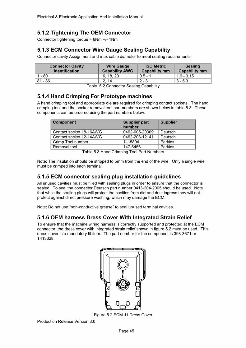
Electrical & Electronic Application And Installation Manual
Production Release Version 3.0 Page 45
5.1.2 Tightening The OEM Connector
Connector tightening torque = 6Nm +/- 1Nm
5.1.3 ECM Connector Wire Gauge Sealing Capability
Connector cavity Assignment and max cable diameter to meet sealing requirements.
Connector Cavity Identification
Wire Gauge Capability AWG
ISO Metric Capability mm
Sealing Capability mm
1 - 80 16, 18, 20 0.5 - 1 1.6 - 3.15
81 - 86 12, 14 2 - 3 3 - 5.3
Table 5.2 Connector Sealing Capability
5.1.4 Hand Crimping For Prototype machines
A hand crimping tool and appropriate die are required for crimping contact sockets. The hand crimping tool and the socket removal tool part numbers are shown below in table 5.3. These components can be ordered using the part numbers below.
Component Supplier part number
Supplier
Contact socket 18-16AWG 0462-005-20309 Deutsch
Contact socket 12-14AWG 0462-203-12141 Deutsch
Crimp Tool number 1U-5804 Perkins
Removal tool 147-6456 Perkins
Table 5.3 Hand Crimping Tool Part Numbers Note: The insulation should be stripped to 5mm from the end of the wire. Only a single wire must be crimped into each terminal.
5.1.5 ECM connector sealing plug installation guidelines All unused cavities must be filled with sealing plugs in order to ensure that the connector is sealed. To seal the connector Deutsch part number 0413-204-2005 should be used. Note that while the sealing plugs will protect the cavities from dirt and dust ingress they will not protect against direct pressure washing, which may damage the ECM. Note: Do not use “non-conductive grease” to seal unused terminal cavities.
5.1.6 OEM harness Dress Cover With Integrated Strain Relief
To ensure that the machine wiring harness is correctly supported and protected at the ECM connector, the dress cover with integrated strain relief shown in figure 5.2 must be used. This dress cover is a mandatory fit item. The part number for the component is 398-3671 or T413628.
Figure 5.2 ECM J1 Dress Cover
Electrical & Electronic Application And Installation Manual
Production Release Version 3.0 Page 46
5.1.7 Machine Crimping For High Volume Production
For high volume and automated crimping solutions please contact the supplier directly for tooling details.
5.2 Engine ECM J1 Connector I/O
Pin Position
ECM Driver Function Contact Size
1 3.75A PWM Driver LS3 Reserved 18AWG
2 3.75A PWM Driver HS2 Keyswitch (DCU) HS 18AWG
3 3.75A PWM Driver LS2 Keyswitch (DCU) LS 18AWG
4 2.5A PWM Driver HS1 Hydraulic Demand Fan Solenoid +
18AWG
5 2A PWM Sourcing 1 DCU Power Relay + 18AWG
6 2A PWM Sourcing 2 Reserved 18AWG
7 2A On/Off Sourcing 1 Engine Fuel Lift Pump 18AWG
8 2A On/Off Sourcing 2 Glow Plugs 18AWG
9 2A On/Off Sourcing 3 Ether start 18AWG
10 3.75A PWM Driver HS3 Reserved 18AWG
11 Fan I/P 1 Fan Speed Sensor (HE) 18AWG
12 2.5A PWM Driver LS1 Hydraulic Demand Fan Solenoid - 18AWG
13 CAN D+ Machine Specific Data Link 18AWG
14 Sourcing Return 3.75A On/Off Sourcing Return 18AWG
15 Sourcing Return 2A PWM Sourcing Return 18AWG
16 300mA Sinking 1 Wait To Start Lamp 18AWG
17 CAN C+ DEF Pump, Soot, NOx(EO), NOx (TO), Def-Q
18AWG
18 CAN C- DEF Pump, Soot, NOx(EO), NOx (TO), Def-Q
18AWG
19 CAN C Shield CAN C Shield 18AWG
20 CDL+ CDL + 18AWG
21 CAN D- Machine Specific Data Link 18AWG
22 CAN D Shield Machine Specific Data Link 18AWG
23 300mA Sinking 3 Oil Pressure Lamp 18AWG
24 300mA Sinking 2 Wait To Disconnect Indicator 18AWG
25 CAN A+ Application Data Link 18AWG
26 CAN A- Application Data Link 18AWG
27 CAN A Shield Application Data Link 18AWG
28 CDL- CDL - 18AWG
29 Analogue Return Passive analogue Return 18AWG
30 Analogue Return Active Analogue Sensor Return 18AWG
31 300mA Sinking 5 Warning/Derate Lamp 18AWG
32 300mA Sinking 4 Shutdown/Stop Lamp 18AWG
33 Passive Analogue I/P 1 Aux Temp Sensor 18AWG
34 Passive Analogue I/P 2 Air Inlet Temp Sensor 18AWG
35 Passive Analogue I/P 3 ATTAC Temp (Or Aux Temp 2) 18AWG
36 STG Return STG Return 18AWG
37 Differential PWM I/P 1(+) Fan Speed Sensor (Passive) + 18AWG
38 Differential PWM I/P 1(-) Fan Speed Sensor (Passive ) - 18AWG
39 300mA Sinking 7 Low DEF Level Lamp 18AWG
40 300mA Sinking 6 Emissions System Failure Lamp 18AWG
41 ACT/Pass Select I/P 2 (Pass) Aftertreatment Ambient Air Temperature Sensor
18AWG
42 ACT/Pass Select I/P 1 (Pass) Reserved 18AWG
43 STG I/P 13 MPTS 4/PTO Set/Lower/Int.Speed Limit
18AWG
44 STG I/P 14 Reserved 18AWG
Electrical & Electronic Application And Installation Manual
Production Release Version 3.0 Page 47
45 Reserved Unassigned 18AWG
46 2A On/Off Sourcing 7 Reserved 18AWG
47 STG I/P 15 Unassigned 18AWG
48 300mA Sinking 8 DES Active Lamp (1206F only) 18AWG
49 Sourcing Return 2A On /Off Sourcing Return 18AWG
50 STG I/P 10 Fan Reverse/Overspeed Verify Switch
18AWG
51 STG I/P 11 MPTS 2/PTO On/Off Switch 18AWG
52 STG I/P 12 MPTS 3/PTO Raise/Resume 18AWG
53 2A On/Off Sourcing 6 Air Shutoff Solenoid 18AWG
54 Sourcing Return Unassigned 18AWG
55 Reserved Unassigned 18AWG
56 8V Supply OEM PWM Temp Sensor, PWM Throttle
18AWG
57 3.5A On/Off Sourcing 1 NOx EO On/Off 18AWG
58 STG I/P 7 Reserved 18AWG
59 STG I/P 8 Unassigned 18AWG
60 STG I/P 9 Coolant Level Switch 18AWG
61 ACT Analogue I/P 1 Aux Pressure Sensor 18AWG
62 ACT Analogue/PWM In 5 DPF In Temp (1206F only) 18AWG
63 ACT Analogue/PWM In 6 SCR In Temp (1206F only) 18AWG
64 Digital Return PWM/Digital Sensor Return 18AWG
65 3.5A On/Off Sourcing 2 NOx to On.Off 18AWG
66 STG I/P 4 Idle validation 2/Throttle Arbitration 1
18AWG
67 STG I/P 5 MPTS 1/PTO Disengage 18AWG
68 STG I/P 6 User Shutdown/PTO Speed 1&2 select
18AWG
69 Key Switch I/P Ignition Key switch 18AWG
70 ACT Analogue/PWM In 3 A/T ID 1-DPF/SCR (Or DPF only) 18AWG
71 ACT Analogue/PWM In 4 Reserved 18AWG
72 5V Supply OEM 5V Analogue Power 18AWG
73 2A On/Off Sourcing 5 Fan Rev/E Fan/Starter Solenoid Relay
18AWG
74 STG I/P 1 Regen Readiness (OK to Elevate Idle)
18AWG
75 STG I/P 2 Idle Validation 1/Customer Fan Override
18AWG
76 STG I/P 3 Water In Fuel switch 18AWG
77 STB I/P 1 Mode switch 1 18AWG
78 STB I/P 2 Mode switch 2/Inlet Air Restriction Switch
18AWG
79 ACT Analogue/PWM In 1 (Prog)
Analogue Throttle 1/PWM Throttle 1
18AWG
80 ACT Analogue/PWM In 2 (Prog)
Analogue Throttle 2/PWM Throttle 2
18AWG
81 Battery - ECM Power Return 14AWG
82 Battery - ECM Power Return 14AWG
83 Battery - ECM Power Return 14AWG
84 Battery + ECM Power Supply 14AWG
85 Battery + ECM Power Supply 14AWG
86 Battery + ECM Power Supply 14AWG
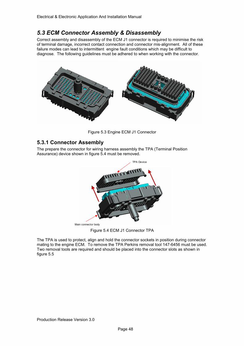
Electrical & Electronic Application And Installation Manual
Production Release Version 3.0 Page 48
5.3 ECM Connector Assembly & Disassembly Correct assembly and disassembly of the ECM J1 connector is required to minimise the risk of terminal damage, incorrect contact connection and connector mis-alignment. All of these failure modes can lead to intermittent engine fault conditions which may be difficult to diagnose. The following guidelines must be adhered to when working with the connector.
Figure 5.3 Engine ECM J1 Connector
5.3.1 Connector Assembly
The prepare the connector for wiring harness assembly the TPA (Terminal Position Assurance) device shown in figure 5.4 must be removed.
Figure 5.4 ECM J1 Connector TPA
The TPA is used to protect, align and hold the connector sockets in position during connector mating to the engine ECM. To remove the TPA Perkins removal tool 147-6456 must be used. Two removal tools are required and should be placed into the connector slots as shown in figure 5.5
Main connector body
TPA Device
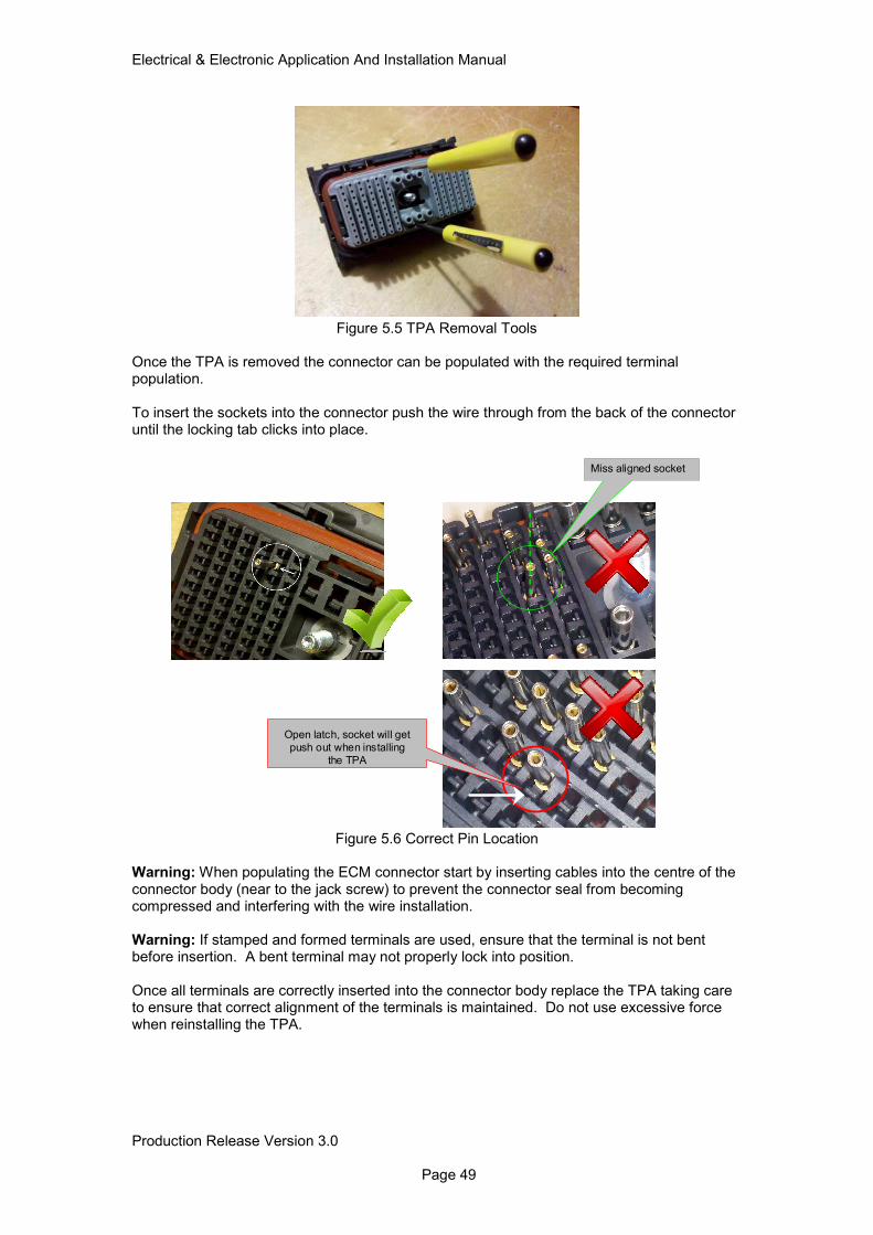
Electrical & Electronic Application And Installation Manual
Production Release Version 3.0 Page 49
Figure 5.5 TPA Removal Tools Once the TPA is removed the connector can be populated with the required terminal population. To insert the sockets into the connector push the wire through from the back of the connector until the locking tab clicks into place.
Figure 5.6 Correct Pin Location Warning: When populating the ECM connector start by inserting cables into the centre of the connector body (near to the jack screw) to prevent the connector seal from becoming compressed and interfering with the wire installation. Warning: If stamped and formed terminals are used, ensure that the terminal is not bent before insertion. A bent terminal may not properly lock into position. Once all terminals are correctly inserted into the connector body replace the TPA taking care to ensure that correct alignment of the terminals is maintained. Do not use excessive force when reinstalling the TPA.
Miss aligned socket
Open latch, socket will get
push out when installing
the TPA
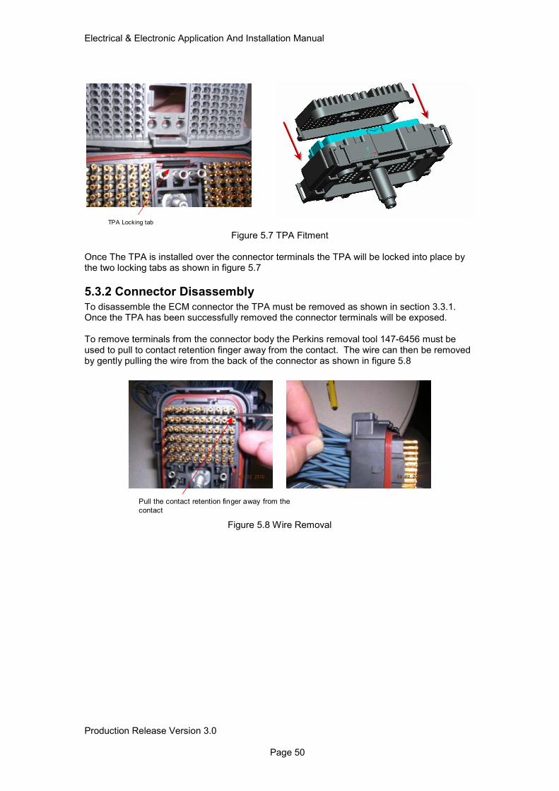
Electrical & Electronic Application And Installation Manual
Production Release Version 3.0 Page 50
Figure 5.7 TPA Fitment
Once The TPA is installed over the connector terminals the TPA will be locked into place by the two locking tabs as shown in figure 5.7
5.3.2 Connector Disassembly
To disassemble the ECM connector the TPA must be removed as shown in section 3.3.1. Once the TPA has been successfully removed the connector terminals will be exposed. To remove terminals from the connector body the Perkins removal tool 147-6456 must be used to pull to contact retention finger away from the contact. The wire can then be removed by gently pulling the wire from the back of the connector as shown in figure 5.8
Figure 5.8 Wire Removal
TPA Locking tab
Pull the contact retention finger away from the
contact
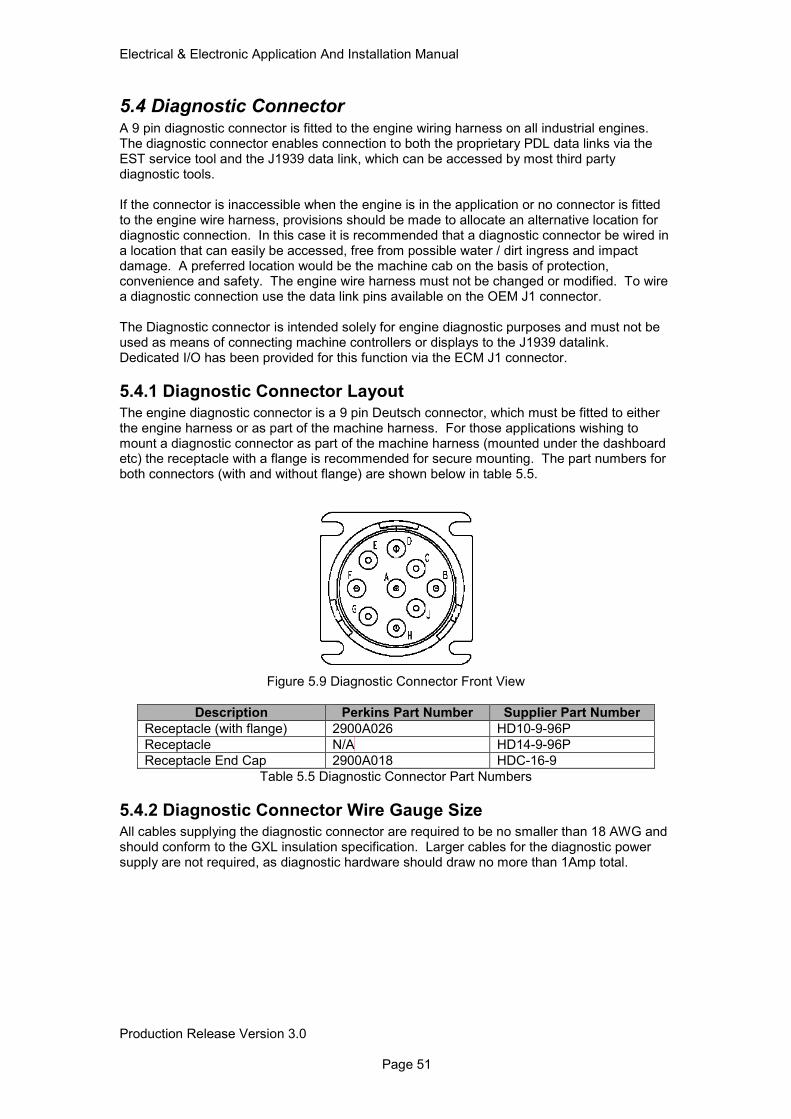
Electrical & Electronic Application And Installation Manual
Production Release Version 3.0 Page 51
5.4 Diagnostic Connector A 9 pin diagnostic connector is fitted to the engine wiring harness on all industrial engines. The diagnostic connector enables connection to both the proprietary PDL data links via the EST service tool and the J1939 data link, which can be accessed by most third party diagnostic tools. If the connector is inaccessible when the engine is in the application or no connector is fitted to the engine wire harness, provisions should be made to allocate an alternative location for diagnostic connection. In this case it is recommended that a diagnostic connector be wired in a location that can easily be accessed, free from possible water / dirt ingress and impact damage. A preferred location would be the machine cab on the basis of protection, convenience and safety. The engine wire harness must not be changed or modified. To wire a diagnostic connection use the data link pins available on the OEM J1 connector. The Diagnostic connector is intended solely for engine diagnostic purposes and must not be used as means of connecting machine controllers or displays to the J1939 datalink. Dedicated I/O has been provided for this function via the ECM J1 connector.
5.4.1 Diagnostic Connector Layout
The engine diagnostic connector is a 9 pin Deutsch connector, which must be fitted to either the engine harness or as part of the machine harness. For those applications wishing to mount a diagnostic connector as part of the machine harness (mounted under the dashboard etc) the receptacle with a flange is recommended for secure mounting. The part numbers for both connectors (with and without flange) are shown below in table 5.5.
Figure 5.9 Diagnostic Connector Front View
Description Perkins Part Number Supplier Part Number
Receptacle (with flange) 2900A026 HD10-9-96P
Receptacle N/A HD14-9-96P
Receptacle End Cap 2900A018 HDC-16-9
Table 5.5 Diagnostic Connector Part Numbers
5.4.2 Diagnostic Connector Wire Gauge Size All cables supplying the diagnostic connector are required to be no smaller than 18 AWG and should conform to the GXL insulation specification. Larger cables for the diagnostic power supply are not required, as diagnostic hardware should draw no more than 1Amp total.
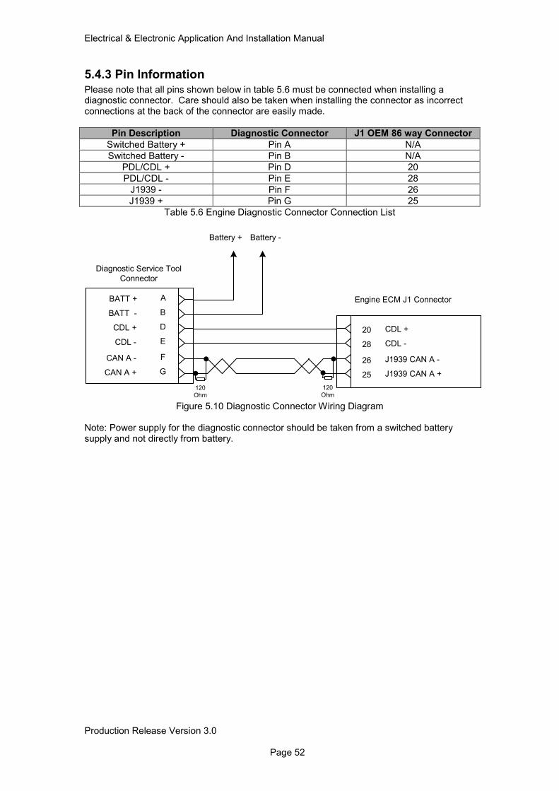
Electrical & Electronic Application And Installation Manual
Production Release Version 3.0 Page 52
5.4.3 Pin Information
Please note that all pins shown below in table 5.6 must be connected when installing a diagnostic connector. Care should also be taken when installing the connector as incorrect connections at the back of the connector are easily made.
Pin Description Diagnostic Connector J1 OEM 86 way Connector
Switched Battery + Pin A N/A
Switched Battery - Pin B N/A
PDL/CDL + Pin D 20
PDL/CDL - Pin E 28
J1939 - Pin F 26
J1939 + Pin G 25
Table 5.6 Engine Diagnostic Connector Connection List
Figure 5.10 Diagnostic Connector Wiring Diagram Note: Power supply for the diagnostic connector should be taken from a switched battery supply and not directly from battery.
ECDL -
DCDL +
BBATT -
ABATT +
GCAN A +
FCAN A -
20 CDL +
28 CDL -
26 J1939 CAN A -
25 J1939 CAN A +
Battery + Battery -
Diagnostic Service Tool
Connector
Engine ECM J1 Connector
120
Ohm120
Ohm
Electrical & Electronic Application And Installation Manual
Production Release Version 3.0 Page 53
5.5 Mandatory Engine & Aftertreatment Connectors Please refer to Appendix 1 for complete connector lists including sealing requirements for GXL wiring systems and terminal part numbers.
5.6 Connector Terminal Contacts There are a number of different terminals available to suit each connector. These terminals and their part numbers are shown in table 5.7. The stamped and formed terminals are available for highly automated harness assembly and should not be used for low volume or field repair of wiring harnesses. Machined terminals are available for these instances and must be used in conjunction with the Perkins crimp tool 1U5804. The machined terminals are also available with nickel and gold plating. The required terminal material for each component connection can be found throughout this document and in Appendix 1. In general other than the engine ECM J1 connector gold plated terminals must be used for all component connections.
Wire Usage (AWG-type)
Contact Type Plating Perkins P/N
Supplier P/N
ECU A5:E2V2 / A5:E12 Connector J1
18/20 GXL Socket Stamped & Formed
Tin TBD 1062-20-0377
12/14 GXL Socket Stamped & Formed
Tin TBD 1062-12-0166
12/14 Socket Machined Nickel 7T-0094 0462-203-12141
16/18 Socket Machined Tin 394-9569 0462-005-20309
HD-10 / DT Connector Standard / Amp Seal
14 Socket St & F Nickel TBD
14 Pin St & F Nickel TBD
14 Socket Machined Nickel T400044 0462-209-16141
14 Pin Machined Nickel T400048 0460-215-16141
16/18 Socket St & F Nickel TBD
16/18 Pin St & F Nickel TBD
16/18 Socket Machined Nickel 2900A009 0462-201-16141
16/18 Pin Machined Nickel T400047 0460-202-16141
14 Socket St & F Gold TBD 776491-1
14 Pin St & F Gold TBD 1060-16-0988
14 Socket Machined Gold 28170024 0462-209-1631
14 Pin Machined Gold TBD 0460-215-1631
16/18 Socket St & F Gold TBD 776491-1
16/18 Pin St & F Gold TBD 1060-16-0988
16/18 Socket Machined Gold 2900A016 0462-201-1631
16/18 Pin Machined Gold 2900A021 0460-202-1631
Table 5.7 Wiring Harness Pins and Sockets List
Electrical & Electronic Application And Installation Manual
Production Release Version 3.0 Page 54
5.7 Wire Specification Requirements The Perkins 4 & 6 cylinder product range is designed to accept the SAE J1128 cable specification. All connectors, seals and terminals shown throughout this document have been specified to suit the SAE J1128 GXL or TXL cabling standard. If other wiring standards are to be used the following points must be considered.
• Cable Insulation Outside Diameter
• Cable Conductor Cross Sectional Area (CSA)
• Temperature Exposure
• Abrasion Risk To ensure all of the above points are taken into consideration please consult the manufacturers cable specification.
5.7.1 Wire Thickness Overview
The following sections provide some guidance on the differences in min/max cable thickness for some of the most popular wiring standards. 5.7.1.1 SAE J1128 GXL GXL cable is the recommended cable size for the connector system used. Using this cable with the specified wire seals and terminals (where appropriate) will result in the correct sealing of the electrical system.
SAE Conductor Size
Wall Thickness Nominal (mm)
Wall Thickness Minimum (mm)
Max Cable Diameter (mm)
20 0.58 0.41 2.40
18 0.58 0.41 2.50
16 0.58 0.41 2.90
14 0.58 0.41 3.20
12 0.66 0.46 3.80
10 0.79 0.55 4.70
5.7.1.2 ISO6722 - Thin Wall Please contact your Applications Engineering department if ISO specification wiring is required.
ISO Conductor Size (mm2)
GXL Equivalent
Dia Wall Thickness Nominal
(mm)
Wall Thickness Minimum
(mm)
Max Cable Diameter
(mm)
0.5 20 1.1 0.28 0.22 1.70
0.75 18 1.3 0.3 0.24 1.90
1 16 1.5 0.3 0.24 2.10
1.25 - 1.7 0.3 0.24 2.30
1.5 - 1.8 0.3 0.24 2.40
2 14 2.0 0.35 0.28 2.80
2.5 - 2.2 0.35 0.28 3.00
3.0 12 2.4 0.4 0.32 3.40
Electrical & Electronic Application And Installation Manual
Production Release Version 3.0 Page 55
5.7.1.3 ISO6722 – Thick Wall Unsuitable for the connector and sealing system used.
ISO Conductor Size (mm2)
GXL Equivalent
Dia Wall Thickness Nominal
(mm)
Wall Thickness Minimum
(mm)
Max Cable Diameter
(mm)
0.5 20 1.1 0.6 0.48 2.3
0.75 18 1.3 0.6 0.48 2.5
1 16 1.5 0.6 0.48 2.7
1.25 - 1.7 0.6 0.48 2.95
1.5 - 1.8 0.6 0.48 3.0
2 14 2.0 0.6 0.48 3.3
2.5 - 2.2 0.7 0.56 3.6
3.0 12 2.4 0.7 0.56 4.1
5.8 Harness Wiring Standards The following are general “good practice” guidelines for wire harness design and installation. It is the responsibility of the machine designer to follow standards appropriate to the application type and to the geographical territory where the machine will be operated. These recommendations do not replace in any way any industrial standards or legal requirements. Please be aware however that any customer installed components, which are integral to the engine or aftertreatment system, are governed by mandatory requirements to ensure the correct operation of the complete system installation. These specific requirements are covered in sections 6 and 9.
5.8.1 Connectors It is strongly recommended that high quality sealed connectors are used throughout. Automotive standard components are not necessarily suitable as they are often only designed for a very low number of disconnect/reconnect cycles. Connectors should be horizontally mounted rather than vertically mounted to prevent ingress of water/chemicals. Whenever possible, connectors should be mounted such that they are protected from direct exposure to extreme cold. Connectors can be damaged by frost if water does penetrate the seals. Cables should not bend close to the connector seals, as the seal quality can be compromised. The correct wire seal must be selected for the diameter of wire used. Cables should be selected of an appropriate cross section for the current and voltage drop requirements Where large numbers of wires go to the same connector, it is essential that no single wire is significantly shorter than the others, such that it placed under exceptional strain. Note: All electrical components and connectors are not designed to withstand direct exposure to high-pressure water.
5.8.2 Harness Bends Near Connectors Harness bends within 25mm of the ECM J1 connector should be avoided. Bending a harness too close to the connector causes the connector seal to be stretched away from the wire, reducing its sealing capability to dirt and moisture. To avoid this the wires should exit perpendicular to the connector before curving as necessary for routing as shown in figure 5.11. Bends near to other sensor or actuator connectors should be no less than twice the wire harness diameter. Special consideration should be made to connectors with large wire
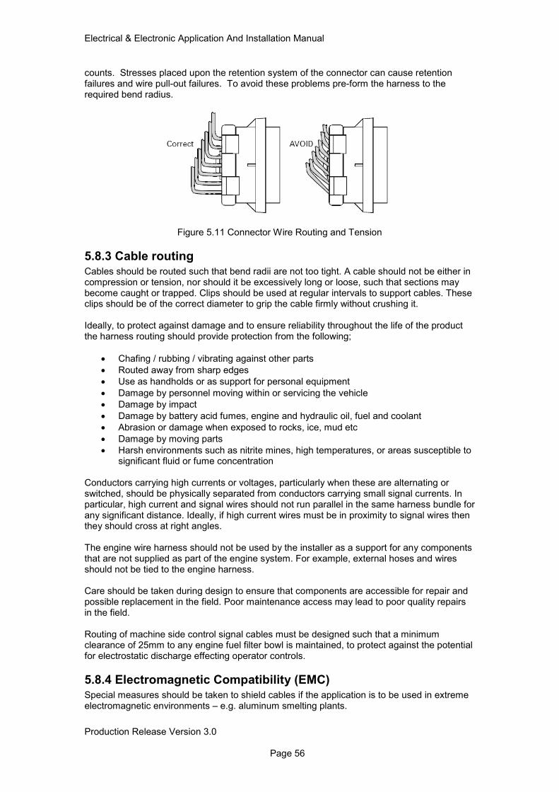
Electrical & Electronic Application And Installation Manual
Production Release Version 3.0 Page 56
counts. Stresses placed upon the retention system of the connector can cause retention failures and wire pull-out failures. To avoid these problems pre-form the harness to the required bend radius.
Figure 5.11 Connector Wire Routing and Tension
5.8.3 Cable routing
Cables should be routed such that bend radii are not too tight. A cable should not be either in compression or tension, nor should it be excessively long or loose, such that sections may become caught or trapped. Clips should be used at regular intervals to support cables. These clips should be of the correct diameter to grip the cable firmly without crushing it. Ideally, to protect against damage and to ensure reliability throughout the life of the product the harness routing should provide protection from the following;
• Chafing / rubbing / vibrating against other parts
• Routed away from sharp edges
• Use as handholds or as support for personal equipment
• Damage by personnel moving within or servicing the vehicle
• Damage by impact
• Damage by battery acid fumes, engine and hydraulic oil, fuel and coolant
• Abrasion or damage when exposed to rocks, ice, mud etc
• Damage by moving parts
• Harsh environments such as nitrite mines, high temperatures, or areas susceptible to significant fluid or fume concentration
Conductors carrying high currents or voltages, particularly when these are alternating or switched, should be physically separated from conductors carrying small signal currents. In particular, high current and signal wires should not run parallel in the same harness bundle for any significant distance. Ideally, if high current wires must be in proximity to signal wires then they should cross at right angles. The engine wire harness should not be used by the installer as a support for any components that are not supplied as part of the engine system. For example, external hoses and wires should not be tied to the engine harness. Care should be taken during design to ensure that components are accessible for repair and possible replacement in the field. Poor maintenance access may lead to poor quality repairs in the field. Routing of machine side control signal cables must be designed such that a minimum clearance of 25mm to any engine fuel filter bowl is maintained, to protect against the potential for electrostatic discharge effecting operator controls.
5.8.4 Electromagnetic Compatibility (EMC)
Special measures should be taken to shield cables if the application is to be used in extreme electromagnetic environments – e.g. aluminum smelting plants.

Electrical & Electronic Application And Installation Manual
Production Release Version 3.0 Page 57
If screened cables are used, the screens should be connected to ground at one point only. That point should be central if possible. In some cases an optional engine electric fuel lift pump ferrite may be required to help machine EMC certification. The Perkins supplied ferrite part number is 472-0078.
5.8.5 Insulation Selection and Thermal Protection
Care must be taken when routing the underhood electrical cabling to ensure that it is routed away from any hot objects such as the engine turbo and exhaust as well as the engine aftertreatment. In some cases this may not be possible in which case care must be taken to ensure that the cable insulation used is rated to the areas in which it is routed. In some cases specialist insulation maybe required such as Teflon etc. It should also be noted that high temperature cables do in many cases have a reduced overall diameter when compared to GXL cable. If this is the case then an analysis of the connector sealing capabilities must be undertaken to ensure that each connector seal maintains its sealing capabilities.
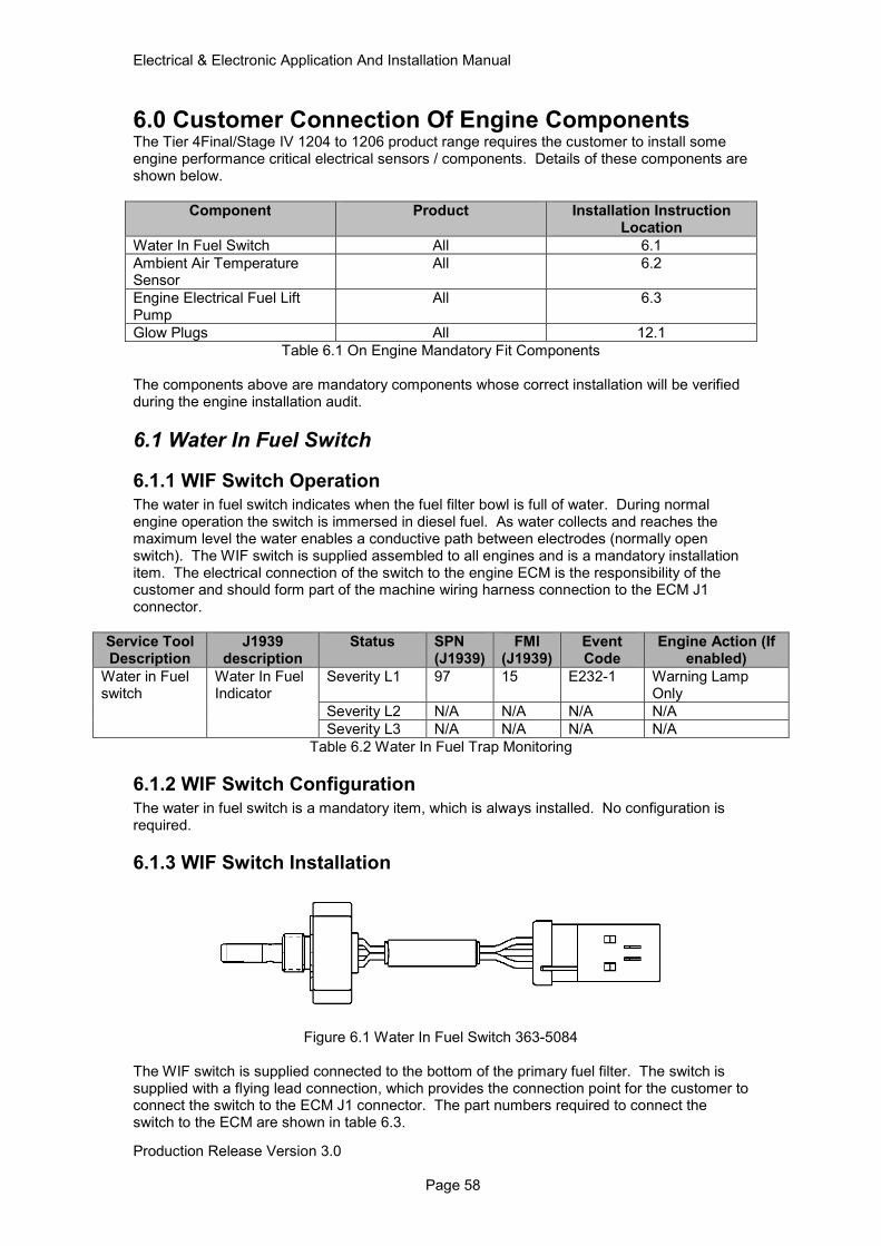
Electrical & Electronic Application And Installation Manual
Production Release Version 3.0 Page 58
6.0 Customer Connection Of Engine Components The Tier 4Final/Stage IV 1204 to 1206 product range requires the customer to install some engine performance critical electrical sensors / components. Details of these components are shown below.
Component Product Installation Instruction Location
Water In Fuel Switch All 6.1
Ambient Air Temperature Sensor
All 6.2
Engine Electrical Fuel Lift Pump
All 6.3
Glow Plugs All 12.1
Table 6.1 On Engine Mandatory Fit Components The components above are mandatory components whose correct installation will be verified during the engine installation audit.
6.1 Water In Fuel Switch
6.1.1 WIF Switch Operation The water in fuel switch indicates when the fuel filter bowl is full of water. During normal engine operation the switch is immersed in diesel fuel. As water collects and reaches the maximum level the water enables a conductive path between electrodes (normally open switch). The WIF switch is supplied assembled to all engines and is a mandatory installation item. The electrical connection of the switch to the engine ECM is the responsibility of the customer and should form part of the machine wiring harness connection to the ECM J1 connector.
Service Tool Description
J1939 description
Status SPN (J1939)
FMI (J1939)
Event Code
Engine Action (If enabled)
Water in Fuel switch
Water In Fuel Indicator
Severity L1 97 15 E232-1 Warning Lamp Only
Severity L2 N/A N/A N/A N/A
Severity L3 N/A N/A N/A N/A
Table 6.2 Water In Fuel Trap Monitoring
6.1.2 WIF Switch Configuration
The water in fuel switch is a mandatory item, which is always installed. No configuration is required.
6.1.3 WIF Switch Installation
Figure 6.1 Water In Fuel Switch 363-5084
The WIF switch is supplied connected to the bottom of the primary fuel filter. The switch is supplied with a flying lead connection, which provides the connection point for the customer to connect the switch to the ECM J1 connector. The part numbers required to connect the switch to the ECM are shown in table 6.3.
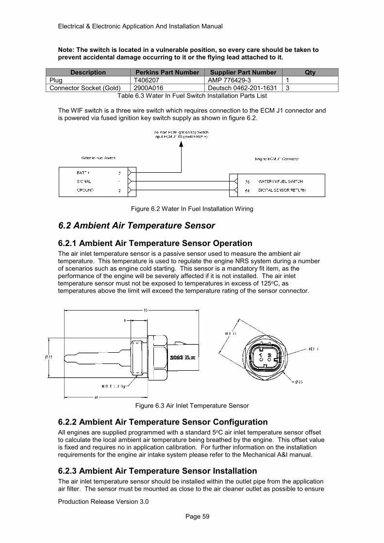
Electrical & Electronic Application And Installation Manual
Production Release Version 3.0 Page 59
Note: The switch is located in a vulnerable position, so every care should be taken to prevent accidental damage occurring to it or the flying lead attached to it.
Description Perkins Part Number Supplier Part Number Qty
Plug T406207 AMP 776429-3 1
Connector Socket (Gold) 2900A016 Deutsch 0462-201-1631 3
Table 6.3 Water In Fuel Switch Installation Parts List The WIF switch is a three wire switch which requires connection to the ECM J1 connector and is powered via fused ignition key switch supply as shown in figure 6.2.
Figure 6.2 Water In Fuel Installation Wiring
6.2 Ambient Air Temperature Sensor
6.2.1 Ambient Air Temperature Sensor Operation The air inlet temperature sensor is a passive sensor used to measure the ambient air temperature. This temperature is used to regulate the engine NRS system during a number of scenarios such as engine cold starting. This sensor is a mandatory fit item, as the performance of the engine will be severely affected if it is not installed. The air inlet temperature sensor must not be exposed to temperatures in excess of 125oC, as temperatures above the limit will exceed the temperature rating of the sensor connector.
Figure 6.3 Air Inlet Temperature Sensor
6.2.2 Ambient Air Temperature Sensor Configuration All engines are supplied programmed with a standard 5oC air inlet temperature sensor offset to calculate the local ambient air temperature being breathed by the engine. This offset value is fixed and requires no in application calibration. For further information on the installation requirements for the engine air intake system please refer to the Mechanical A&I manual.
6.2.3 Ambient Air Temperature Sensor Installation
The air inlet temperature sensor should be installed within the outlet pipe from the application air filter. The sensor must be mounted as close to the air cleaner outlet as possible to ensure
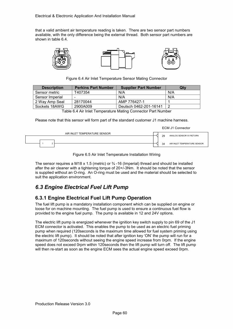
Electrical & Electronic Application And Installation Manual
Production Release Version 3.0 Page 60
that a valid ambient air temperature reading is taken. There are two sensor part numbers available, with the only difference being the external thread. Both sensor part numbers are shown in table 6.4.
Figure 6.4 Air Inlet Temperature Sensor Mating Connector
Description Perkins Part Number Supplier Part Number Qty
Sensor metric T407354 N/A N/A
Sensor Imperial - N/A N/A
2 Way Amp Seal 28170044 AMP 776427-1 1
Sockets 18AWG 2900A009 Deutsch 0462-201-16141 2
Table 6.4 Air Inlet Temperature Mating Connector Part Number Please note that this sensor will form part of the standard customer J1 machine harness.
Figure 6.5 Air Inlet Temperature Installation Wiring
The sensor requires a M18 x 1.5 (metric) or ¾ -16 (Imperial) thread and should be installed after the air cleaner with a tightening torque of 20+/-3Nm. It should be noted that the sensor is supplied without an O-ring. An O-ring must be used and the material should be selected to suit the application environment.
6.3 Engine Electrical Fuel Lift Pump
6.3.1 Engine Electrical Fuel Lift Pump Operation
The fuel lift pump is a mandatory installation component which can be supplied on engine or loose for on machine mounting. The fuel pump is used to ensure a continuous fuel flow is provided to the engine fuel pump. The pump is available in 12 and 24V options. The electric lift pump is energized whenever the ignition key switch supply to pin 69 of the J1 ECM connector is activated. This enables the pump to be used as an electric fuel priming pump when required (120seconds is the maximum time allowed for fuel system priming using the electric lift pump). It should be noted that after ignition key ‘ON’ the pump will run for a maximum of 120seconds without seeing the engine speed increase from 0rpm. If the engine speed does not exceed 0rpm within 120seconds then the lift pump will turn off. The lift pump will then re-start as soon as the engine ECM sees the actual engine speed exceed 0rpm.
ECM J1 Connector
29 ANALOG SENSOR 5V RETURN
34 AIR INLET TEMPERATURE SENSOR1 2
AIR INLET TEMPERATURE SENSOR
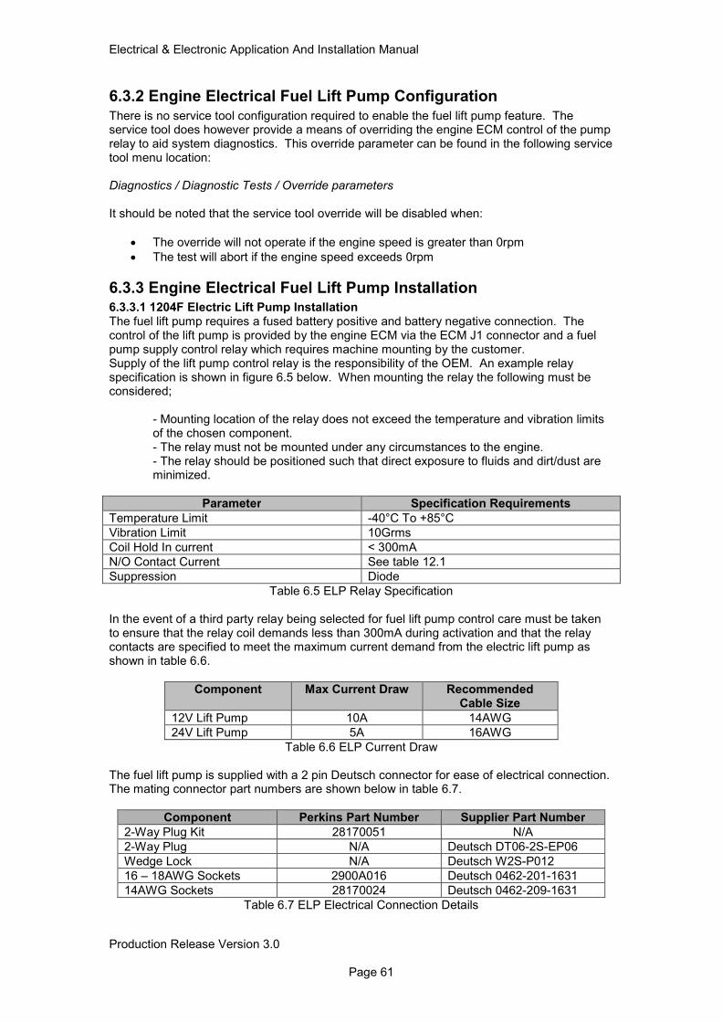
Electrical & Electronic Application And Installation Manual
Production Release Version 3.0 Page 61
6.3.2 Engine Electrical Fuel Lift Pump Configuration
There is no service tool configuration required to enable the fuel lift pump feature. The service tool does however provide a means of overriding the engine ECM control of the pump relay to aid system diagnostics. This override parameter can be found in the following service tool menu location: Diagnostics / Diagnostic Tests / Override parameters It should be noted that the service tool override will be disabled when:
• The override will not operate if the engine speed is greater than 0rpm
• The test will abort if the engine speed exceeds 0rpm
6.3.3 Engine Electrical Fuel Lift Pump Installation 6.3.3.1 1204F Electric Lift Pump Installation The fuel lift pump requires a fused battery positive and battery negative connection. The control of the lift pump is provided by the engine ECM via the ECM J1 connector and a fuel pump supply control relay which requires machine mounting by the customer. Supply of the lift pump control relay is the responsibility of the OEM. An example relay specification is shown in figure 6.5 below. When mounting the relay the following must be considered;
- Mounting location of the relay does not exceed the temperature and vibration limits of the chosen component. - The relay must not be mounted under any circumstances to the engine. - The relay should be positioned such that direct exposure to fluids and dirt/dust are minimized.
Parameter Specification Requirements
Temperature Limit -40°C To +85°C
Vibration Limit 10Grms
Coil Hold In current < 300mA
N/O Contact Current See table 12.1
Suppression Diode
Table 6.5 ELP Relay Specification
In the event of a third party relay being selected for fuel lift pump control care must be taken to ensure that the relay coil demands less than 300mA during activation and that the relay contacts are specified to meet the maximum current demand from the electric lift pump as shown in table 6.6.
Component Max Current Draw Recommended Cable Size
12V Lift Pump 10A 14AWG
24V Lift Pump 5A 16AWG
Table 6.6 ELP Current Draw
The fuel lift pump is supplied with a 2 pin Deutsch connector for ease of electrical connection. The mating connector part numbers are shown below in table 6.7.
Component Perkins Part Number Supplier Part Number
2-Way Plug Kit 28170051 N/A
2-Way Plug N/A Deutsch DT06-2S-EP06
Wedge Lock N/A Deutsch W2S-P012
16 – 18AWG Sockets 2900A016 Deutsch 0462-201-1631
14AWG Sockets 28170024 Deutsch 0462-209-1631
Table 6.7 ELP Electrical Connection Details
Electrical & Electronic Application And Installation Manual
Production Release Version 3.0 Page 62
Fuse (
See
Note
A)
Figure 6.6 ELP Installation Schematic
Note A: The lift pump supply cables and the associated fuse rating will be dependent upon the overall system voltage. Table 6.6 gives details of the max continuous current rating for each pump. The fuse rating selected should be specified to protect the cable size used. Note: For more information regarding mechanical installation and mounting please refer to the Mechanical A&I Manual. 6.3.3.2 1206F Electric Lift Pump Installation The 1206F product range is supplied with an engine harness connection point for the electrical connection of the electric lift pump. The engine harness connector is a 2 way connector that provides direct control of the lift pump via the ECM J2 connector. It should also be noted that for those engines built with on engine lift pump options the electrical connection to the ECM J2 connector is supplied. All Off engine electrical lift pump options will require the 2 way connector part number shown in table 6.8. Connection of the should be made as shown below.
Description Perkins Part Number
Supplier Part Number Qty
Engine Harness 2 way receptacle kit
TBD N/A 1
2 way receptacle TBD Deutsch DT04-2P-E005 N/A
2 way receptacle Wedge Lock
TBD W2P-P004 N/A
Fuel Pump 2 way connector kit
28170051 N/A 1
2 way Plug N/A Deutsch DT06-2S-EP06 N/A
2 Way Plug Wedge Lock
N/A Deutsch W2S-P012 N/A
14AWG Sockets 28170024 Deutsch 0462-209-1631 2
14AWG Pins 28170023 Deutsch 0460-215-1631 2
Table 6.8 Electric Lift Pump Connector Part Numbers

Electrical & Electronic Application And Installation Manual
Production Release Version 3.0 Page 63
Figure 6.7 ELP Wiring Note: For more information regarding mechanical installation and mounting please refer to the Mechanical A&I Manual.
1
2
ENGINE FUEL LIFT
PUMP +
RETURN
Engine harness 2
way Connector
1
2
ENGINE FUEL LIFT
PUMP +
RETURN
Fuel Pump 2 way
Connector
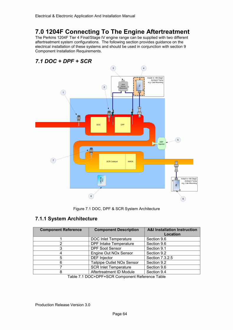
Electrical & Electronic Application And Installation Manual
Production Release Version 3.0 Page 64
7.0 1204F Connecting To The Engine Aftertreatment The Perkins 1204F Tier 4 Final/Stage IV engine range can be supplied with two different aftertreatment system configurations. The following section provides guidance on the electrical installation of these systems and should be used in conjunction with section 9 Component Installation Requirements.
7.1 DOC + DPF + SCR
Figure 7.1 DOC, DPF & SCR System Architecture
7.1.1 System Architecture
Component Reference Component Description A&I Installation Instruction Location
1 DOC Inlet Temperature Section 9.6
2 DPF Intake Temperature Section 9.6
3 DPF Soot Sensor Section 9.1
4 Engine Out NOx Sensor Section 9.2
5 DEF Injector Section 7.3.2.5
6 Tailpipe Outlet NOx Sensor Section 9.2
7 SCR Inlet Temperature Section 9.6
8 Aftertreatment ID Module Section 9.4
Table 7.1 DOC+DPF+SCR Component Reference Table
Install In <85 DegC
Ambient Temp
e.g. Cab Mounting
Install In <85 DegC
Ambient Temp
e.g. Cab Mounting
DOC DPF
SCR Catalyst AMOX
DEF
Injector
Soot
Sensor
Electronics
1
2
3
7
6
5
4
8
Electrical & Electronic Application And Installation Manual
Production Release Version 3.0 Page 65
7.1.2 Electrical Connections
The DOC+DPF+SCR aftertreatment systems are supplied directly from the factory with all components shown in figure 7.1. Some components are supplied fitted to the aftertreatment system whilst others must be fitted by the customer. The table below provides an overview for the mounting requirements of each sensor. For further information regarding the specific installation criteria for each component please refer to section 8.
Component On AT Module Additional Requirements
DOC Inlet Temperature Sensor
Yes Requires Wiring Back to Tenneco XNOx Connector By OEM
DPF Intake Temperature Sensor
Yes Requires Wiring Back to Tenneco XNOx connector By OEM
DPF Soot Sensor Antenna Yes Control Box Loose part
Control box requires machine mounting and wiring back to ECM J1 By OEM
Engine Out NOx Sensor
No Sensor must be fitted and wired back to ECM J1 Connector by OEM
DEF Injector Yes Requires Wiring Back to Tenneco XNOx Connector By OEM
Tailpipe Outlet NOx Sensor
No Sensor must be fitted and wired back to ECM J1 Connector by OEM
SCR Inlet Temperature Sensor
Yes Requires Wiring Back to Tenneco XNOx Connector By OEM
Aftertreatment ID Module
Yes Requires wiring back to the engine ECM J1 connector by OEM
Table 7.2 DOC+DPF+SCR Connection Requirements
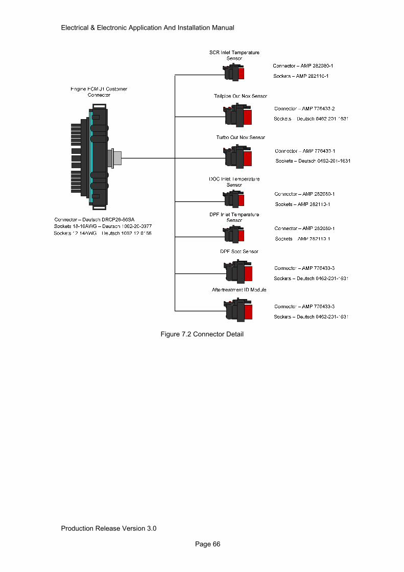
Electrical & Electronic Application And Installation Manual
Production Release Version 3.0 Page 66
Figure 7.2 Connector Detail
Electrical & Electronic Application And Installation Manual
Production Release Version 3.0 Page 67
7.1.3 Component I/O 7.1.3.1 DOC Inlet Temperature Sensor
Pin Description Perkins P/N Supplier P/N To Pin
1 XRDG (0V) TBD AMP 282110-1 XNOx Con (24)
2 DOC Inlet Temp TBD AMP 282110-1 XNOx Con (9)
7.1.3.2 SCR Inlet Temperature Sensor
Pin Description Perkins P/N Supplier P/N To Pin
1 XRDG (0V) TBD AMP 282110-1 XNOx Con (24)
2 SCR Inlet Temp TBD AMP 282110-1 XNOx Con (8)
7.1.3.3 DPF Inlet Temperature Sensor
Pin Description Perkins P/N Supplier P/N To Pin
1 XRDG (0V) TBD AMP 282110-1 XNOx Con (24)
2 DPF Inlet Temp TBD AMP 282110-1 XNOx Con (10)
7.1.3.4 DPF Soot Sensor
Pin Description Perkins P/N Supplier P/N To Pin
1 Switched Batt + 2900A016 Deutsch 0462-201-1631 N/A
2 Ground 2900A016 Deutsch 0462-201-1631 N/A
3 Reserved 2900A011 Deutsch 114017 N/A
4 CAN C J1939 - 2900A016 Deutsch 0462-201-1631 ECM J1 (18)
5 CAN C J1939 + 2900A016 Deutsch 0462-201-1631 ECM J1 (17)
6 Shield 2900A011 Deutsch 114017 N/A
7.1.3.5 Tailpipe Outlet Nox Sensor
Pin Description Perkins P/N Supplier P/N To Pin
1 ECM Controlled Batt +
2900A016 Deutsch 0462-201-1631 ECM J1 (65)
2 J1939 - 2900A011 Deutsch 114017 N/A
3 Address Select 2900A011 Deutsch 114017 N/A
4 Ground 2900A016 Deutsch 0462-201-1631 ECM J1 (14)
5 CAN C J1939 - 2900A016 Deutsch 0462-201-1631 ECM J1 (18)
6 CAN C J1939 + 2900A016 Deutsch 0462-201-1631 ECM J1 (17)
7.1.3.6 Turbo Out Nox Sensor
Pin Description Perkins P/N Supplier P/N To Pin
1 ECM Controlled Batt +
2900A016 Deutsch 0462-201-1631 ECM J1 (57)
2 J1939 - 2900A011 Deutsch 114017 N/A
3 Address Select 2900A011 Deutsch 114017 N/A
4 Ground 2900A016 Deutsch 0462-201-1631 ECM J1 (14)
5 CAN C J1939 - 2900A016 Deutsch 0462-201-1631 ECM J1 (18)
6 CAN C J1939 + 2900A016 Deutsch 0462-201-1631 ECM J1 (17)
7.1.3.7 Aftertreatment ID Module
Pin Description Perkins P/N Supplier P/N To Pin
1 5V Sensor Supply 2900A016 Deutsch 0462-201-1631 ECM J1 (72)
2 Reserved 2900A011 Deutsch 114017 N/A
3 Signal 2900A016 Deutsch 0462-201-1631 ECM J1 (70)
4 Reserved 2900A011 Deutsch 114017 N/A
5 Reserved 2900A011 Deutsch 114017 N/A
6 Ground 2900A016 Deutsch 0462-201-1631 ECM J1 (64)
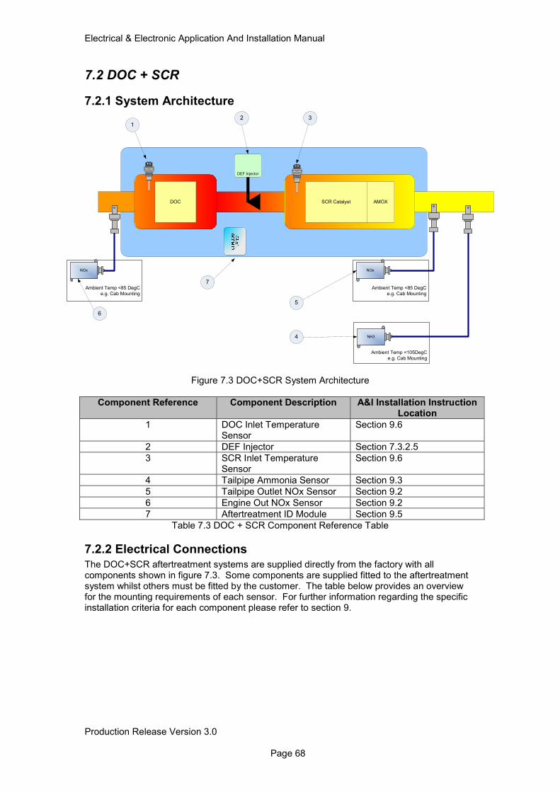
Electrical & Electronic Application And Installation Manual
Production Release Version 3.0 Page 68
7.2 DOC + SCR
7.2.1 System Architecture
Figure 7.3 DOC+SCR System Architecture
Component Reference Component Description A&I Installation Instruction Location
1 DOC Inlet Temperature Sensor
Section 9.6
2 DEF Injector Section 7.3.2.5
3 SCR Inlet Temperature Sensor
Section 9.6
4 Tailpipe Ammonia Sensor Section 9.3
5 Tailpipe Outlet NOx Sensor Section 9.2
6 Engine Out NOx Sensor Section 9.2
7 Aftertreatment ID Module Section 9.5
Table 7.3 DOC + SCR Component Reference Table
7.2.2 Electrical Connections
The DOC+SCR aftertreatment systems are supplied directly from the factory with all components shown in figure 7.3. Some components are supplied fitted to the aftertreatment system whilst others must be fitted by the customer. The table below provides an overview for the mounting requirements of each sensor. For further information regarding the specific installation criteria for each component please refer to section 9.
Ambient Temp <85 DegC
e.g. Cab Mounting
DOC SCR Catalyst AMOX
Ambient Temp <85 DegC
e.g. Cab Mounting
NOx
DEF Injector
NOx
Ambient Temp <105DegC
e.g. Cab Mounting
NH3
1
6
2 3
5
4
7
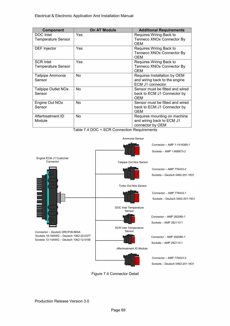
Electrical & Electronic Application And Installation Manual
Production Release Version 3.0 Page 69
Component On AT Module Additional Requirements
DOC Inlet Temperature Sensor
Yes Requires Wiring Back to Tenneco XNOx Connector By OEM
DEF Injector Yes Requires Wiring Back to Tenneco XNOx Connector By OEM
SCR Inlet Temperature Sensor
Yes Requires Wiring Back to Tenneco XNOx Connector By OEM
Tailpipe Ammonia Sensor
No Requires Installation by OEM and wiring back to the engine ECM J1 connector
Tailpipe Outlet NOx Sensor
No Sensor must be fitted and wired back to ECM J1 Connector by OEM
Engine Out NOx Sensor
No Sensor must be fitted and wired back to ECM J1 Connector by OEM
Aftertreatment ID Module
No Requires mounting on machine and wiring back to ECM J1 connector by OEM
Table 7.4 DOC + SCR Connection Requirements
Tailpipe Out Nox Sensor
Turbo Out Nox Sensor
DOC Inlet Temperature
Sensor
Engine ECM J1 Customer
Connector
Connector – AMP 776433-2
Sockets – Deutsch 0462-201-1631
Connector – AMP 776433-1
Sockets – Deutsch 0462-201-1631
Connector – AMP 282080-1
Sockets – AMP 282110-1
SCR Inlet Temperature
Sensor
Connector – AMP 282080-1
Sockets – AMP 282110-1
Ammonia Sensor
Sockets – AMP 1-968873-2
Connector – AMP 1-1418390-1
Connector – Deutsch DRCP28-86SA
Sockets 18-16AWG – Deutsch 1062-20-0377
Sockets 12-14AWG – Deutsch 1062-12-0166
Aftertreatment ID Module
Connector – AMP 776433-3
Sockets – Deutsch 0462-201-1631
Figure 7.4 Connector Detail
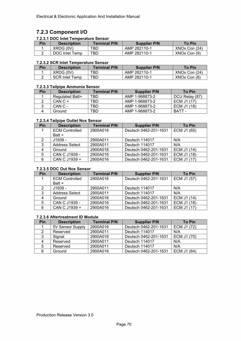
Electrical & Electronic Application And Installation Manual
Production Release Version 3.0 Page 70
7.2.3 Component I/O 7.2.3.1 DOC Inlet Temperature Sensor
Pin Description Terminal P/N Supplier P/N To Pin
1 XRDG (0V) TBD AMP 282110-1 XNOx Con (24)
2 DOC Inlet Temp TBD AMP 282110-1 XNOx Con (9)
7.2.3.2 SCR Inlet Temperature Sensor
Pin Description Terminal P/N Supplier P/N To Pin
1 XRDG (0V) TBD AMP 282110-1 XNOx Con (24)
2 SCR Inlet Temp TBD AMP 282110-1 XNOx Con (8)
7.2.3.3 Tailpipe Ammonia Sensor
Pin Description Terminal P/N Supplier P/N To Pin
1 Regulated Batt+ TBD AMP 1-968873-2 DCU Relay (87)
2 CAN C + TBD AMP 1-968873-2 ECM J1 (17)
3 CAN C - TBD AMP 1-968873-2 ECM J1 (18)
4 Ground TBD AMP 1-968873-2 BATT -
7.2.3.4 Tailpipe Outlet Nox Sensor
Pin Description Terminal P/N Supplier P/N To Pin
1 ECM Controlled Batt +
2900A016 Deutsch 0462-201-1631 ECM J1 (65)
2 J1939 - 2900A011 Deutsch 114017 N/A
3 Address Select 2900A011 Deutsch 114017 N/A
4 Ground 2900A016 Deutsch 0462-201-1631 ECM J1 (14)
5 CAN C J1939 - 2900A016 Deutsch 0462-201-1631 ECM J1 (18)
6 CAN C J1939 + 2900A016 Deutsch 0462-201-1631 ECM J1 (17)
7.2.3.5 DOC Out Nox Sensor
Pin Description Terminal P/N Supplier P/N To Pin
1 ECM Controlled Batt +
2900A016 Deutsch 0462-201-1631 ECM J1 (57)
2 J1939 - 2900A011 Deutsch 114017 N/A
3 Address Select 2900A011 Deutsch 114017 N/A
4 Ground 2900A016 Deutsch 0462-201-1631 ECM J1 (14)
5 CAN C J1939 - 2900A016 Deutsch 0462-201-1631 ECM J1 (18)
6 CAN C J1939 + 2900A016 Deutsch 0462-201-1631 ECM J1 (17)
7.2.3.6 Aftertreatment ID Module
Pin Description Terminal P/N Supplier P/N To Pin
1 5V Sensor Supply 2900A016 Deutsch 0462-201-1631 ECM J1 (72)
2 Reserved 2900A011 Deutsch 114017 N/A
3 Signal 2900A016 Deutsch 0462-201-1631 ECM J1 (70)
4 Reserved 2900A011 Deutsch 114017 N/A
5 Reserved 2900A011 Deutsch 114017 N/A
6 Ground 2900A016 Deutsch 0462-201-1631 ECM J1 (64)
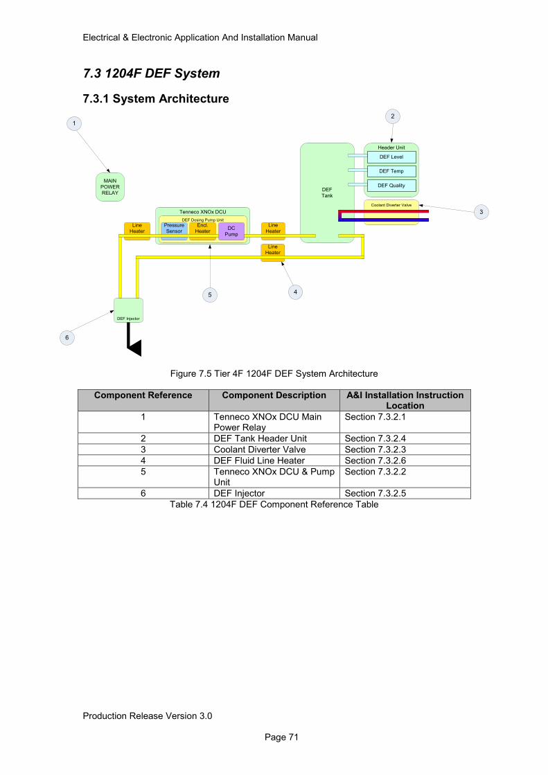
Electrical & Electronic Application And Installation Manual
Production Release Version 3.0 Page 71
7.3 1204F DEF System
7.3.1 System Architecture
Figure 7.5 Tier 4F 1204F DEF System Architecture
Component Reference Component Description A&I Installation Instruction Location
1 Tenneco XNOx DCU Main Power Relay
Section 7.3.2.1
2 DEF Tank Header Unit Section 7.3.2.4
3 Coolant Diverter Valve Section 7.3.2.3
4 DEF Fluid Line Heater Section 7.3.2.6
5 Tenneco XNOx DCU & Pump Unit
Section 7.3.2.2
6 DEF Injector Section 7.3.2.5
Table 7.4 1204F DEF Component Reference Table
Line
Heater
Header Unit
DEF
Tank
Line
Heater
Coolant Diverter Valve
DEF Level
DEF Temp
Tenneco XNOx DCU
DEF Injector
DEF Quality
DEF Dosing Pump Unit
Encl.
Heater
Pressure
SensorDC
Pump
Line
Heater
MAIN
POWER
RELAY
1
6
2
54
3
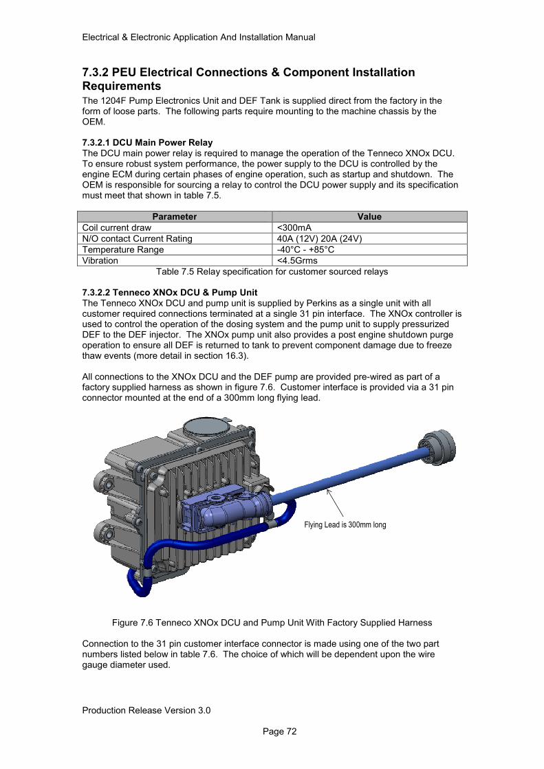
Electrical & Electronic Application And Installation Manual
Production Release Version 3.0 Page 72
7.3.2 PEU Electrical Connections & Component Installation Requirements The 1204F Pump Electronics Unit and DEF Tank is supplied direct from the factory in the form of loose parts. The following parts require mounting to the machine chassis by the OEM.
7.3.2.1 DCU Main Power Relay The DCU main power relay is required to manage the operation of the Tenneco XNOx DCU. To ensure robust system performance, the power supply to the DCU is controlled by the engine ECM during certain phases of engine operation, such as startup and shutdown. The OEM is responsible for sourcing a relay to control the DCU power supply and its specification must meet that shown in table 7.5.
Parameter Value
Coil current draw <300mA
N/O contact Current Rating 40A (12V) 20A (24V)
Temperature Range -40°C - +85°C
Vibration <4.5Grms
Table 7.5 Relay specification for customer sourced relays 7.3.2.2 Tenneco XNOx DCU & Pump Unit The Tenneco XNOx DCU and pump unit is supplied by Perkins as a single unit with all customer required connections terminated at a single 31 pin interface. The XNOx controller is used to control the operation of the dosing system and the pump unit to supply pressurized DEF to the DEF injector. The XNOx pump unit also provides a post engine shutdown purge operation to ensure all DEF is returned to tank to prevent component damage due to freeze thaw events (more detail in section 16.3). All connections to the XNOx DCU and the DEF pump are provided pre-wired as part of a factory supplied harness as shown in figure 7.6. Customer interface is provided via a 31 pin connector mounted at the end of a 300mm long flying lead.
Flying Lead is 300mm long
Figure 7.6 Tenneco XNOx DCU and Pump Unit With Factory Supplied Harness
Connection to the 31 pin customer interface connector is made using one of the two part numbers listed below in table 7.6. The choice of which will be dependent upon the wire gauge diameter used.
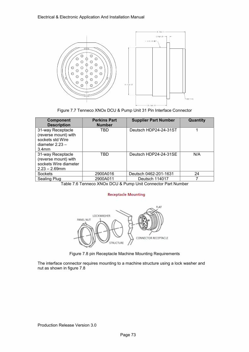
Electrical & Electronic Application And Installation Manual
Production Release Version 3.0 Page 73
Figure 7.7 Tenneco XNOx DCU & Pump Unit 31 Pin Interface Connector
Component Description
Perkins Part Number
Supplier Part Number Quantity
31-way Receptacle (reverse mount) with sockets std Wire diameter 2.23 – 3.4mm
TBD Deutsch HDP24-24-31ST 1
31-way Receptacle (reverse mount) with sockets Wire diameter 2.23 – 2.69mm
TBD Deutsch HDP24-24-31SE N/A
Sockets 2900A016 Deutsch 0462-201-1631 24
Sealing Plug 2900A011 Deutsch 114017 7
Table 7.6 Tenneco XNOx DCU & Pump Unit Connector Part Number
Figure 7.8 pin Receptacle Machine Mounting Requirements
The interface connector requires mounting to a machine structure using a lock washer and nut as shown in figure 7.8
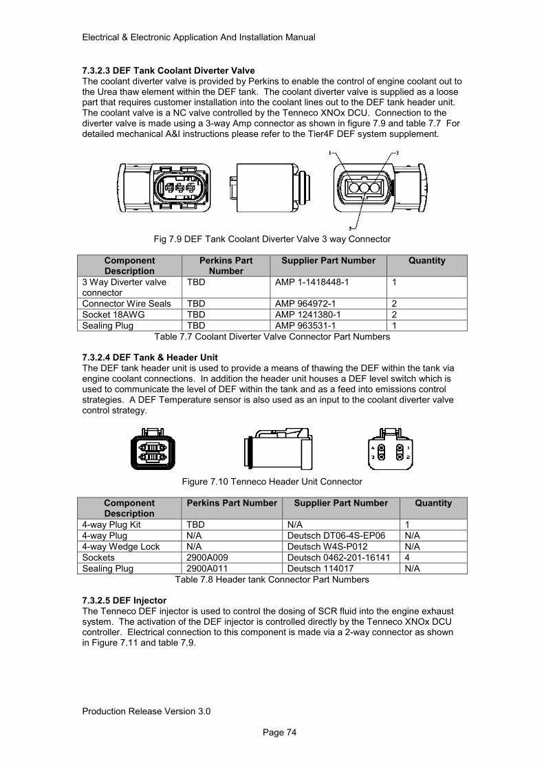
Electrical & Electronic Application And Installation Manual
Production Release Version 3.0 Page 74
7.3.2.3 DEF Tank Coolant Diverter Valve The coolant diverter valve is provided by Perkins to enable the control of engine coolant out to the Urea thaw element within the DEF tank. The coolant diverter valve is supplied as a loose part that requires customer installation into the coolant lines out to the DEF tank header unit. The coolant valve is a NC valve controlled by the Tenneco XNOx DCU. Connection to the diverter valve is made using a 3-way Amp connector as shown in figure 7.9 and table 7.7 For detailed mechanical A&I instructions please refer to the Tier4F DEF system supplement.
Fig 7.9 DEF Tank Coolant Diverter Valve 3 way Connector
Component Description
Perkins Part Number
Supplier Part Number Quantity
3 Way Diverter valve connector
TBD AMP 1-1418448-1 1
Connector Wire Seals TBD AMP 964972-1 2
Socket 18AWG TBD AMP 1241380-1 2
Sealing Plug TBD AMP 963531-1 1
Table 7.7 Coolant Diverter Valve Connector Part Numbers 7.3.2.4 DEF Tank & Header Unit The DEF tank header unit is used to provide a means of thawing the DEF within the tank via engine coolant connections. In addition the header unit houses a DEF level switch which is used to communicate the level of DEF within the tank and as a feed into emissions control strategies. A DEF Temperature sensor is also used as an input to the coolant diverter valve control strategy.
Figure 7.10 Tenneco Header Unit Connector
Component Description
Perkins Part Number Supplier Part Number Quantity
4-way Plug Kit TBD N/A 1
4-way Plug N/A Deutsch DT06-4S-EP06 N/A
4-way Wedge Lock N/A Deutsch W4S-P012 N/A
Sockets 2900A009 Deutsch 0462-201-16141 4
Sealing Plug 2900A011 Deutsch 114017 N/A
Table 7.8 Header tank Connector Part Numbers 7.3.2.5 DEF Injector The Tenneco DEF injector is used to control the dosing of SCR fluid into the engine exhaust system. The activation of the DEF injector is controlled directly by the Tenneco XNOx DCU controller. Electrical connection to this component is made via a 2-way connector as shown in Figure 7.11 and table 7.9.
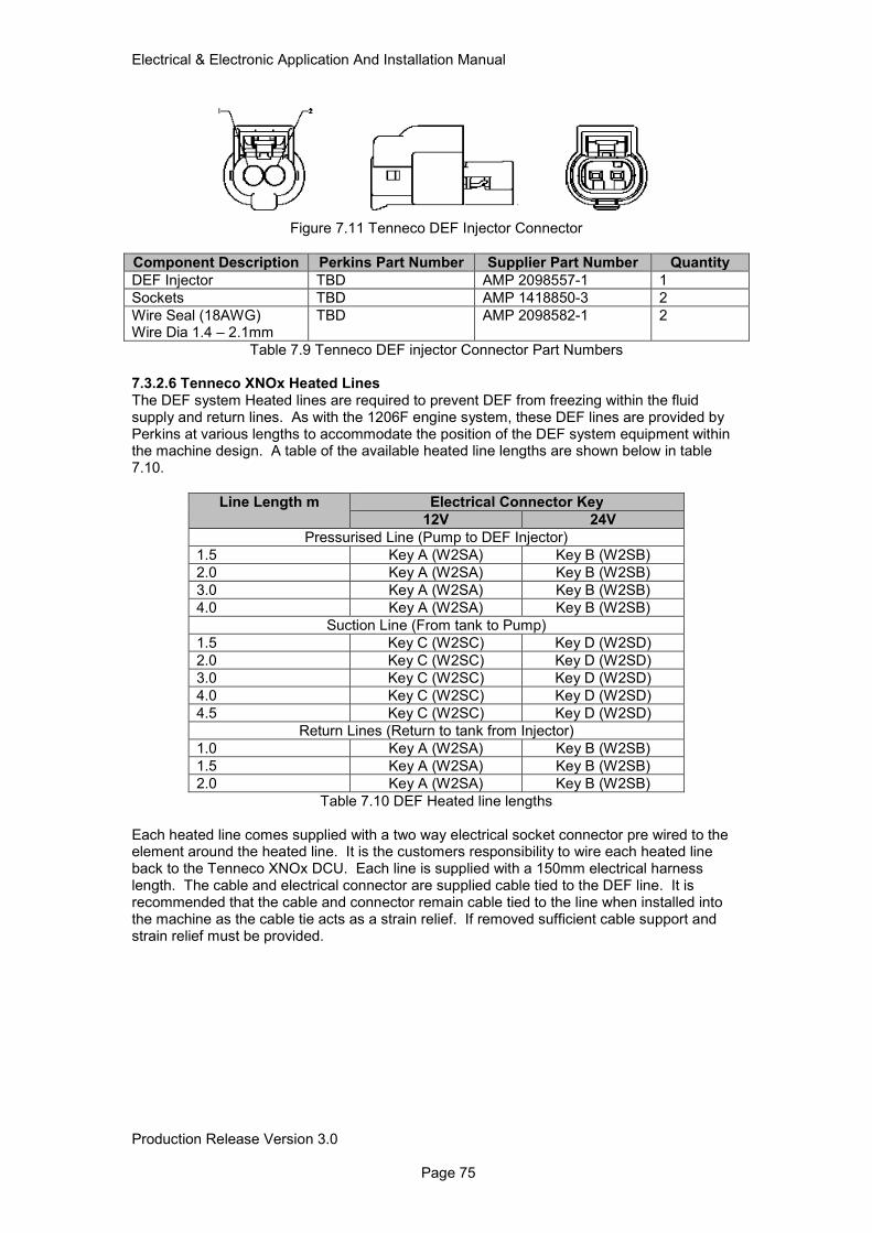
Electrical & Electronic Application And Installation Manual
Production Release Version 3.0 Page 75
Figure 7.11 Tenneco DEF Injector Connector
Component Description Perkins Part Number Supplier Part Number Quantity
DEF Injector TBD AMP 2098557-1 1
Sockets TBD AMP 1418850-3 2
Wire Seal (18AWG) Wire Dia 1.4 – 2.1mm
TBD AMP 2098582-1 2
Table 7.9 Tenneco DEF injector Connector Part Numbers 7.3.2.6 Tenneco XNOx Heated Lines The DEF system Heated lines are required to prevent DEF from freezing within the fluid supply and return lines. As with the 1206F engine system, these DEF lines are provided by Perkins at various lengths to accommodate the position of the DEF system equipment within the machine design. A table of the available heated line lengths are shown below in table 7.10.
Line Length m Electrical Connector Key
12V 24V
Pressurised Line (Pump to DEF Injector)
1.5 Key A (W2SA) Key B (W2SB)
2.0 Key A (W2SA) Key B (W2SB)
3.0 Key A (W2SA) Key B (W2SB)
4.0 Key A (W2SA) Key B (W2SB)
Suction Line (From tank to Pump)
1.5 Key C (W2SC) Key D (W2SD)
2.0 Key C (W2SC) Key D (W2SD)
3.0 Key C (W2SC) Key D (W2SD)
4.0 Key C (W2SC) Key D (W2SD)
4.5 Key C (W2SC) Key D (W2SD)
Return Lines (Return to tank from Injector)
1.0 Key A (W2SA) Key B (W2SB)
1.5 Key A (W2SA) Key B (W2SB)
2.0 Key A (W2SA) Key B (W2SB)
Table 7.10 DEF Heated line lengths
Each heated line comes supplied with a two way electrical socket connector pre wired to the element around the heated line. It is the customers responsibility to wire each heated line back to the Tenneco XNOx DCU. Each line is supplied with a 150mm electrical harness length. The cable and electrical connector are supplied cable tied to the DEF line. It is recommended that the cable and connector remain cable tied to the line when installed into the machine as the cable tie acts as a strain relief. If removed sufficient cable support and strain relief must be provided.
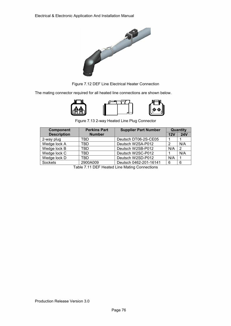
Electrical & Electronic Application And Installation Manual
Production Release Version 3.0 Page 76
Figure 7.12 DEF Line Electrical Heater Connection
The mating connector required for all heated line connections are shown below.
Figure 7.13 2-way Heated Line Plug Connector
Component Description
Perkins Part Number
Supplier Part Number Quantity
12V 24V
2-way plug TBD Deutsch DT06-2S-CE05 1 1
Wedge lock A TBD Deutsch W2SA-P012 2 N/A
Wedge lock B TBD Deutsch W2SB-P012 N/A 2
Wedge lock C TBD Deutsch W2SC-P012 1 N/A
Wedge lock D TBD Deutsch W2SD-P012 N/A 1
Sockets 2900A009 Deutsch 0462-201-16141 6 6
Table 7.11 DEF Heated Line Mating Connections
Electrical & Electronic Application And Installation Manual
Production Release Version 3.0 Page 77
7.3.3 Component I/O 7.3.3.1 DCU Main Power Relay
Pin Description Terminal P/N To Pin
30 Main Power Feed Customer Selected Fused Batt +
85 Coil + Customer Selected ECM J1 (5)
86 Coil - Customer Selected ECM J1 (15)
87 Power Out Normally Open Contact Customer Selected Ammonia (1) DEF Header Unit (4) XNOx DCU (56, 59, 62)
87A NC Contact Customer Selected N/A
7.3.3.2 Tenneco XNOx DCU & Pump Unit Interface Connector
Pin Description Perkins P/N Terminal P/N To Pin
1 ACU Supply (B+) TBD Deutsch 0462-201-1631
XNOx Relay (87)
2 ACU Supply (B+) TBD Deutsch 0462-201-1631
XNOx Relay (87)
3 ACU Supply (B+) TBD Deutsch 0462-201-1631
XNOx Relay (87)
4 Ignition TBD Deutsch 0462-201-1631
ECM J1 (2&3)
5 ACU Supply (B-) TBD Deutsch 0462-201-1631
BATT -
6 ACU Supply (B-) TBD Deutsch 0462-201-1631
BATT -
7 ACU Supply (B-) TBD Deutsch 0462-201-1631
BATT -
8 Pre-SCR Temperature TBD Deutsch 0462-201-1631
SCR T (2)
9 Pre-Doc Temperature TBD Deutsch 0462-201-1631
DOC T (2)
10 Pre-DPF Temperature TBD Deutsch 0462-201-1631
DPF T (2)
11 PH Injector + TBD Deutsch 0462-201-1631
DEF Inj (1)
12 PH Injector - TBD Deutsch 0462-201-1631
DEF Inj (2)
13 DRVP2 TBD Deutsch 0462-201-1631
Heated Line 1 (1)
14 Line 1 Heater (Suction) TBD Deutsch 0462-201-1631
Heated Line 1 (2)
15 DRVP 3 TBD Deutsch 0462-201-1631
Heated Line 2 (1)
16 Line 2 Heater (Delivery) TBD Deutsch 0462-201-1631
Heated Line 2 (2)
17 DRVP 4 TBD Deutsch 0462-201-1631
Coolant Valve(1) Heated Line 3 (1)
18 Line 3 Heater (Return) TBD Deutsch 0462-201-1631
Heated Line 3 (2)
19 Coolant Valve Control TBD Deutsch 0462-201-1631
Coolant Valve (3)
20 CAN A + TBD Deutsch 0462-201-1631
ECM J1 (25)
21 CAN A - TBD Deutsch 0462-201-1631
ECM J1 (26)
22 CAN C + TBD Deutsch 0462-201- ECM J1 (17)
Electrical & Electronic Application And Installation Manual
Production Release Version 3.0 Page 78
1631
23 CAN C - TBD Deutsch 0462-201-1631
ECM J1 (18)
24 XDRG (0V) TBD Deutsch 0462-201-1631
SCR T (1) DOC T (1) DPF T (1)
25 Not Used 2900A011 Deutsch 114017 N/A
26 Not Used 2900A011 Deutsch 114017 N/A
27 Not Used 2900A011 Deutsch 114017 N/A
28 Not Used 2900A011 Deutsch 114017 N/A
29 Not Used 2900A011 Deutsch 114017 N/A
30 Not Used 2900A011 Deutsch 114017 N/A
31 Not Used 2900A011 Deutsch 114017 N/A
7.3.3.3 DEF Tank Diverter Valve
Pin Description Perkins P/N Terminal P/N To Pin
1 High Side Connection
TBD AMP 1241380-1 XNOx Con (17)
2 N/A TBD AMP 963531-1 N/A
3 Low Side Connection TBD AMP 1241380-1 XNOx Con (19)
7.3.3.4 DEF Tank Header Unit
Pin Description Perkins P/N Terminal P/N To Pin
1 J1939 CAN C - 2900A009 Deutsch 0462-201-16141 ECM J1 (18)
2 J1939 CAN C + 2900A009 Deutsch 0462-201-16141 ECM J1 (17)
3 Ground 2900A009 Deutsch 0462-201-16141 BATT -
4 Regulated Batt+ 2900A009 Deutsch 0462-201-16141 DCU Relay (87)
7.3.3.5 DEF Injector
Pin Description Perkins P/N Terminal P/N To Pin
1 PH Injector + TBD AMP 1418850-3 XNOx Con (11)
2 PH Injector - TBD AMP 1418850-3 XNOx Con (12)
7.3.3.6 Tenneco Xnox Heated Lines Line 1
Pin Description Perkins P/N Terminal P/N To Pin
1 DRVP2 2900A009 Deutsch 0462-201-16141 XNOx Con (13)
2 Line 1 Heater (Suction) LS
2900A009 Deutsch 0462-201-16141 XNOx Con (14)
Line 2
Pin Description Perkins P/N Terminal P/N To Pin
1 DRVP3 2900A009 Deutsch 0462-201-16141 XNOx Con (15)
2 Line 2 Heater (Delivery) LS
2900A009 Deutsch 0462-201-16141 XNOx Con (16)
Line 3
Pin Description Perkins P/N Terminal P/N To Pin
1 DRVP4 2900A009 Deutsch 0462-201-16141 XNOx Con (17)
2 Line 3 Heater (Return) LS
2900A009 Deutsch 0462-201-16141 XNOx Con (18)

Electrical & Electronic Application And Installation Manual
Production Release Version 3.0 Page 79
7.4 1204F Aftertreatment wiring Schematics
7.4.1 1204F DOC & SCR Schematic
Note 1: Selected fuse must be specified to meet cable requirements and system current requirements as detailed in table 4.2.2.
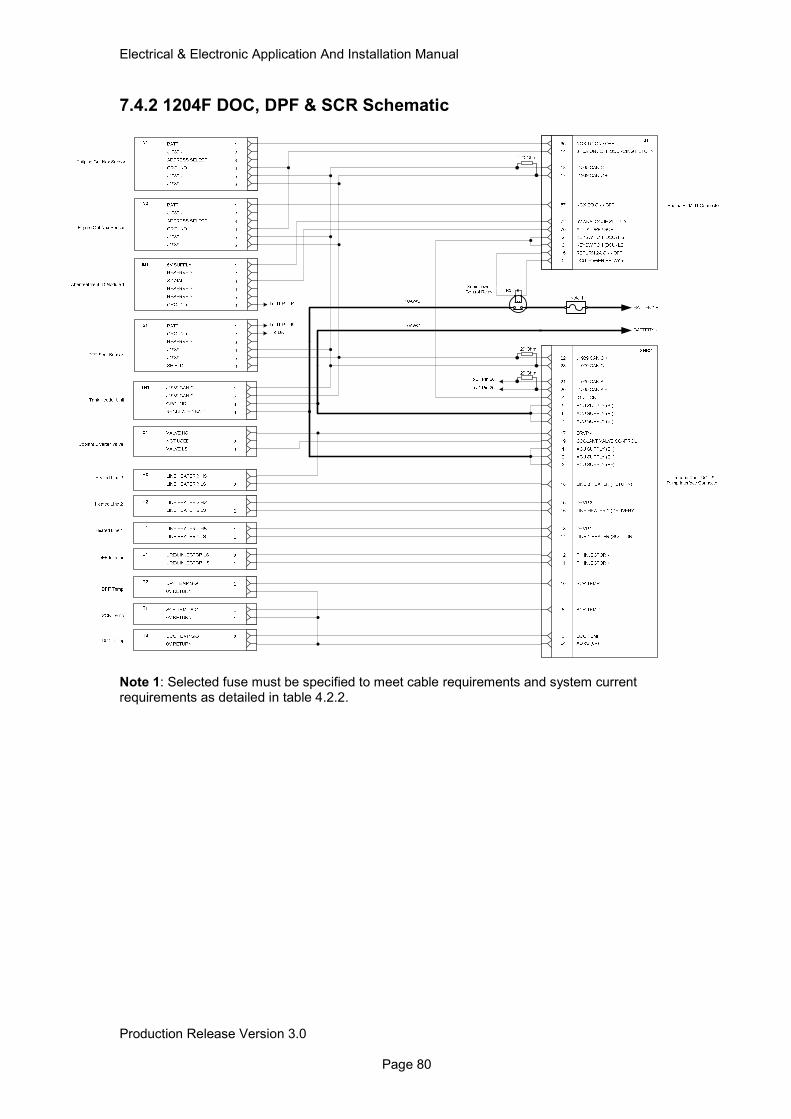
Electrical & Electronic Application And Installation Manual
Production Release Version 3.0 Page 80
7.4.2 1204F DOC, DPF & SCR Schematic
Note 1: Selected fuse must be specified to meet cable requirements and system current requirements as detailed in table 4.2.2.
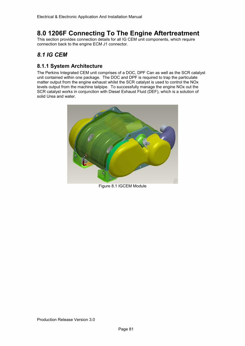
Electrical & Electronic Application And Installation Manual
Production Release Version 3.0 Page 81
8.0 1206F Connecting To The Engine Aftertreatment This section provides connection details for all IG CEM unit components, which require connection back to the engine ECM J1 connector.
8.1 IG CEM
8.1.1 System Architecture
The Perkins Integrated CEM unit comprises of a DOC, DPF Can as well as the SCR catalyst unit contained within one package. The DOC and DPF is required to trap the particulate matter output from the engine exhaust whilst the SCR catalyst is used to control the NOx levels output from the machine tailpipe. To successfully manage the engine NOx out the SCR catalyst works in conjunction with Diesel Exhaust Fluid (DEF), which is a solution of solid Urea and water.
Figure 8.1 IGCEM Module
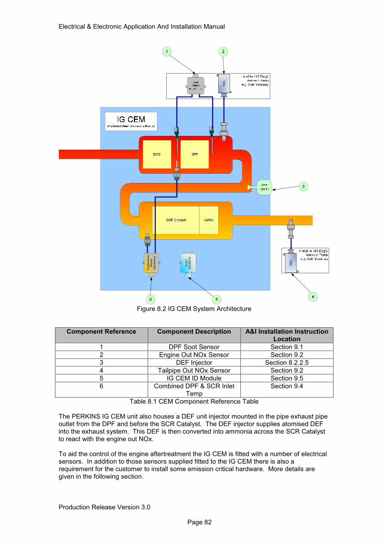
Electrical & Electronic Application And Installation Manual
Production Release Version 3.0 Page 82
Te
mp
era
ture
Se
nso
r
Ele
ctr
on
ics
A1
:E1
IGC
EM
ID
NO
x
NO
x
Figure 8.2 IG CEM System Architecture
Component Reference Component Description A&I Installation Instruction Location
1 DPF Soot Sensor Section 9.1
2 Engine Out NOx Sensor Section 9.2
3 DEF Injector Section 8.2.2.5
4 Tailpipe Out NOx Sensor Section 9.2
5 IG CEM ID Module Section 9.5
6 Combined DPF & SCR Inlet Temp
Section 9.4
Table 8.1 CEM Component Reference Table
The PERKINS IG CEM unit also houses a DEF unit injector mounted in the pipe exhaust pipe outlet from the DPF and before the SCR Catalyst. The DEF injector supplies atomised DEF into the exhaust system. This DEF is then converted into ammonia across the SCR Catalyst to react with the engine out NOx. To aid the control of the engine aftertreatment the IG CEM is fitted with a number of electrical sensors. In addition to those sensors supplied fitted to the IG CEM there is also a requirement for the customer to install some emission critical hardware. More details are given in the following section.
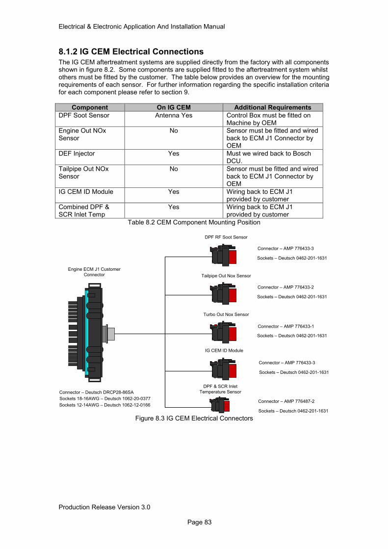
Electrical & Electronic Application And Installation Manual
Production Release Version 3.0 Page 83
8.1.2 IG CEM Electrical Connections
The IG CEM aftertreatment systems are supplied directly from the factory with all components shown in figure 8.2. Some components are supplied fitted to the aftertreatment system whilst others must be fitted by the customer. The table below provides an overview for the mounting requirements of each sensor. For further information regarding the specific installation criteria for each component please refer to section 9.
Component On IG CEM Additional Requirements
DPF Soot Sensor Antenna Yes Control Box must be fitted on Machine by OEM
Engine Out NOx Sensor
No Sensor must be fitted and wired back to ECM J1 Connector by OEM
DEF Injector Yes Must we wired back to Bosch DCU.
Tailpipe Out NOx Sensor
No Sensor must be fitted and wired back to ECM J1 Connector by OEM
IG CEM ID Module Yes Wiring back to ECM J1 provided by customer
Combined DPF & SCR Inlet Temp
Yes Wiring back to ECM J1 provided by customer
Table 8.2 CEM Component Mounting Position
DPF RF Soot Sensor
Tailpipe Out Nox Sensor
Turbo Out Nox Sensor
IG CEM ID Module
DPF & SCR Inlet
Temperature Sensor
Engine ECM J1 Customer
Connector
Connector – AMP 776433-3
Sockets – Deutsch 0462-201-1631
Connector – AMP 776433-2
Sockets – Deutsch 0462-201-1631
Connector – AMP 776433-1
Sockets – Deutsch 0462-201-1631
Connector – AMP 776433-3
Sockets – Deutsch 0462-201-1631
Connector – AMP 776487-2
Sockets – Deutsch 0462-201-1631
Connector – Deutsch DRCP28-86SA
Sockets 18-16AWG – Deutsch 1062-20-0377
Sockets 12-14AWG – Deutsch 1062-12-0166
Figure 8.3 IG CEM Electrical Connectors
Electrical & Electronic Application And Installation Manual
Production Release Version 3.0 Page 84
8.1.3 Component I/O 8.1.3.1 Engine ECM J1 Connector
Pin Description Perkins P/N Terminal P/N To Pin
14 3.75A On OFF Sourcing Return
TBD Deutsch1062-20-0377 Tailpipe Out Nox (4) Engine Out Nox (4)
17 J1939 CAN C+ TBD Deutsch1062-20-0377 DPF Soot Sensor (5) Tailpipe Out Nox (6) Engine Out Nox (6)
18 J1939 CAN C- TBD Deutsch1062-20-0377 DPF Soot Sensor (4) Tailpipe Out Nox (5) Engine Out Nox (5)
56 8V Supply OEM TBD Deutsch1062-20-0377 DPF + SCR Temp Sensor (1)
57 NOX EO ON / OFF TBD Deutsch1062-20-0377 Engine Out Nox (1)
62 DPF In Temp TBD Deutsch1062-20-0377 DPF + SCR Temp Sensor (3)
63 SCR In Temp TBD Deutsch1062-20-0377 DPF + SCR Temp Sensor (4)
64 Digital Return TBD Deutsch1062-20-0377 DPF + SCR Temp Sensor (2) IG CEM ID (6)
65 NOX TO ON / OFF TBD Deutsch1062-20-0377 Tailpipe Out Nox (1)
70 AT ID1 – DPF + SCR
TBD Deutsch1062-20-0377 IG CEM ID (3)
72 5V Analogue Power TBD Deutsch1062-20-0377 IG CEM ID (1)
8.1.3.2 DPF Soot Sensor Connector
Pin Description Perkins P/N Terminal P/N To Pin
1 Switched Batt + 2900A016 Deutsch 0462-201-1631 N/A
2 Ground 2900A016 Deutsch 0462-201-1631 N/A
3 Reserved 2900A011 Deutsch 114017 N/A
4 CAN C J1939 - 2900A016 Deutsch 0462-201-1631 ECM J1 (18)
5 CAN C J1939 + 2900A016 Deutsch 0462-201-1631 ECM J1 (17)
6 Shield 2900A011 Deutsch 114017 N/A
Electrical & Electronic Application And Installation Manual
Production Release Version 3.0 Page 85
8.1.3.3 Engine Out Nox Sensor Connector
Pin Description Perkins P/N Terminal P/N To Pin
1 ECM Controlled Batt +
2900A016 Deutsch 0462-201-1631 ECM J1 (57)
2 N/A 2900A011 Deutsch 114017 N/A
3 N/A 2900A011 Deutsch 114017 N/A
4 Ground 2900A016 Deutsch 0462-201-1631 ECM J1 (14)
5 CAN C J1939 - 2900A016 Deutsch 0462-201-1631 ECM J1 (18)
6 CAN C J1939 + 2900A016 Deutsch 0462-201-1631 ECM J1 (17)
8.1.3.4 Tailpipe Out Nox Sensor Connector
Pin Description Perkins P/N Terminal P/N To Pin
1 ECM Controlled Batt +
2900A016 Deutsch 0462-201-1631 ECM J1 (65)
2 N/A 2900A011 Deutsch 114017 N/A
3 N/A 2900A011 Deutsch 114017 N/A
4 Ground 2900A016 Deutsch 0462-201-1631 ECM J1 (14)
5 CAN C J1939 - 2900A016 Deutsch 0462-201-1631 ECM J1 (18)
6 CAN C J1939 + 2900A016 Deutsch 0462-201-1631 ECM J1 (17)
8.1.3.5 IG CEM ID Module Connector
Pin Description Perkins P/N Terminal P/N To Pin
1 5V Sensor Supply 2900A016 Deutsch 0462-201-1631 ECM J1 (72)
2 Reserved 2900A011 Deutsch 114017 N/A
3 Signal 2900A016 Deutsch 0462-201-1631 ECM J1 (70)
4 Reserved 2900A011 Deutsch 114017 N/A
5 Reserved 2900A011 Deutsch 114017 N/A
6 Ground 2900A016 Deutsch 0462-201-1631 ECM J1 (64)
8.1.3.6 Combined DPF & SCR Inlet Temp Sensor Connector
Pin Description Perkins P/N Terminal P/N To Pin
1 +8V Sensor Supply 2900A016 Deutsch 0462-201-1631 ECM J1 (56)
2 Digital Sensor Return
2900A016 Deutsch 0462-201-1631 ECM J1 (64)
3 DPF In Temp Sig 2900A016 Deutsch 0462-201-1631 ECM J1 (62)
4 SCR In Temp Sig 2900A016 Deutsch 0462-201-1631 ECM J1 (63)
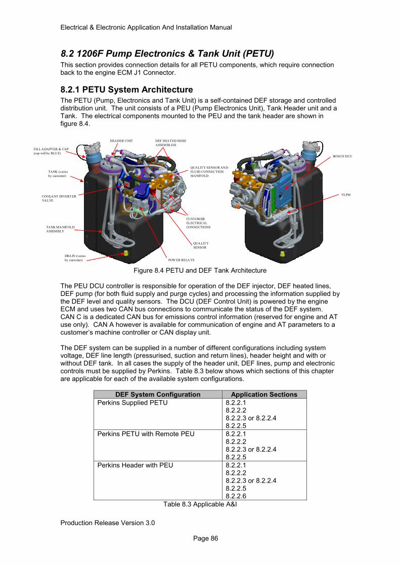
Electrical & Electronic Application And Installation Manual
Production Release Version 3.0 Page 86
8.2 1206F Pump Electronics & Tank Unit (PETU) This section provides connection details for all PETU components, which require connection back to the engine ECM J1 Connector.
8.2.1 PETU System Architecture The PETU (Pump, Electronics and Tank Unit) is a self-contained DEF storage and controlled distribution unit. The unit consists of a PEU (Pump Electronics Unit), Tank Header unit and a Tank. The electrical components mounted to the PEU and the tank header are shown in figure 8.4.
Figure 8.4 PETU and DEF Tank Architecture The PEU DCU controller is responsible for operation of the DEF injector, DEF heated lines, DEF pump (for both fluid supply and purge cycles) and processing the information supplied by the DEF level and quality sensors. The DCU (DEF Control Unit) is powered by the engine ECM and uses two CAN bus connections to communicate the status of the DEF system. CAN C is a dedicated CAN bus for emissions control information (reserved for engine and AT use only). CAN A however is available for communication of engine and AT parameters to a customer’s machine controller or CAN display unit. The DEF system can be supplied in a number of different configurations including system voltage, DEF line length (pressurised, suction and return lines), header height and with or without DEF tank. In all cases the supply of the header unit, DEF lines, pump and electronic controls must be supplied by Perkins. Table 8.3 below shows which sections of this chapter are applicable for each of the available system configurations.
DEF System Configuration Application Sections
Perkins Supplied PETU 8.2.2.1 8.2.2.2 8.2.2.3 or 8.2.2.4 8.2.2.5
Perkins PETU with Remote PEU 8.2.2.1 8.2.2.2 8.2.2.3 or 8.2.2.4 8.2.2.5
Perkins Header with PEU 8.2.2.1 8.2.2.2 8.2.2.3 or 8.2.2.4 8.2.2.5 8.2.2.6
Table 8.3 Applicable A&I
FILL ADAPTER & CAP
(cap will be BLUE)
TANK (varies
by customer)
DRAIN (varies
by customer)
QUA LITY
SENSOR
COOLANT DIVERTER
VALVE
POW ER RELA YS
TANK MA NIFOLD
ASSEMBLY
DEF HEATED HOSE
ASSEMBLIES
QUALITY SENSOR AND
FLUID CONNECTION
MANIFOLD
CUSTOMER
ELECTRICAL
CONNECTIONS
HEADER UNIT
BOSCH DCU
VLPM
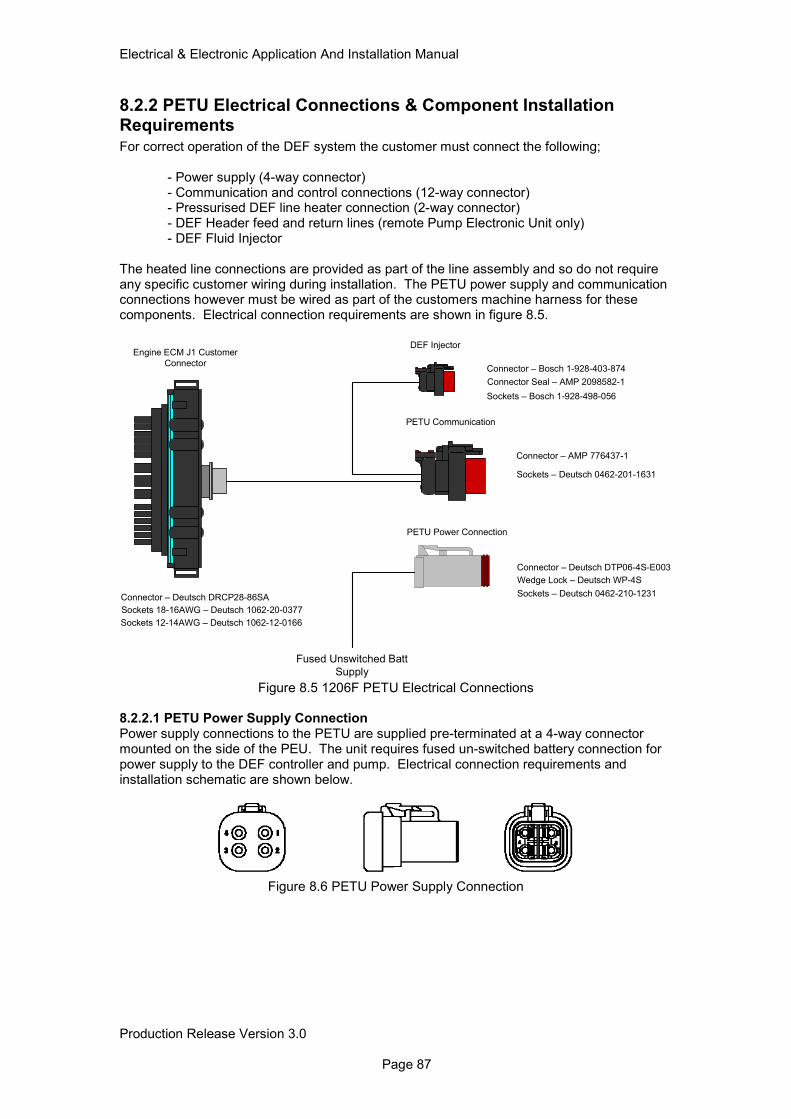
Electrical & Electronic Application And Installation Manual
Production Release Version 3.0 Page 87
8.2.2 PETU Electrical Connections & Component Installation Requirements For correct operation of the DEF system the customer must connect the following;
- Power supply (4-way connector) - Communication and control connections (12-way connector) - Pressurised DEF line heater connection (2-way connector) - DEF Header feed and return lines (remote Pump Electronic Unit only) - DEF Fluid Injector
The heated line connections are provided as part of the line assembly and so do not require any specific customer wiring during installation. The PETU power supply and communication connections however must be wired as part of the customers machine harness for these components. Electrical connection requirements are shown in figure 8.5.
PETU Communication
Connector – AMP 776437-1
Sockets – Deutsch 0462-201-1631
Connector Seal – AMP 2098582-1
Connector – Deutsch DTP06-4S-E003
Engine ECM J1 Customer
Connector
DEF Injector
Connector – Bosch 1-928-403-874
Sockets – Bosch 1-928-498-056
Fused Unswitched Batt
Supply
Sockets – Deutsch 0462-210-1231
Wedge Lock – Deutsch WP-4S
PETU Power Connection
Connector – Deutsch DRCP28-86SA
Sockets 18-16AWG – Deutsch 1062-20-0377
Sockets 12-14AWG – Deutsch 1062-12-0166
Figure 8.5 1206F PETU Electrical Connections
8.2.2.1 PETU Power Supply Connection Power supply connections to the PETU are supplied pre-terminated at a 4-way connector mounted on the side of the PEU. The unit requires fused un-switched battery connection for power supply to the DEF controller and pump. Electrical connection requirements and installation schematic are shown below.
Figure 8.6 PETU Power Supply Connection
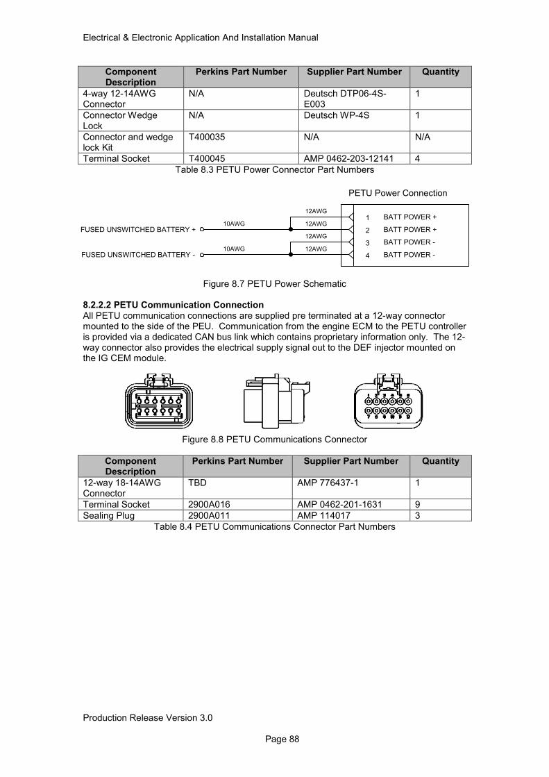
Electrical & Electronic Application And Installation Manual
Production Release Version 3.0 Page 88
Component Description
Perkins Part Number Supplier Part Number Quantity
4-way 12-14AWG Connector
N/A Deutsch DTP06-4S-E003
1
Connector Wedge Lock
N/A Deutsch WP-4S 1
Connector and wedge lock Kit
T400035 N/A N/A
Terminal Socket T400045 AMP 0462-203-12141 4
Table 8.3 PETU Power Connector Part Numbers
Figure 8.7 PETU Power Schematic
8.2.2.2 PETU Communication Connection All PETU communication connections are supplied pre terminated at a 12-way connector mounted to the side of the PEU. Communication from the engine ECM to the PETU controller is provided via a dedicated CAN bus link which contains proprietary information only. The 12-way connector also provides the electrical supply signal out to the DEF injector mounted on the IG CEM module.
Figure 8.8 PETU Communications Connector
Component Description
Perkins Part Number Supplier Part Number Quantity
12-way 18-14AWG Connector
TBD AMP 776437-1 1
Terminal Socket 2900A016 AMP 0462-201-1631 9
Sealing Plug 2900A011 AMP 114017 3
Table 8.4 PETU Communications Connector Part Numbers
1 BATT POWER +
2 BATT POWER +
3 BATT POWER -
4 BATT POWER -
PETU Power Connection
FUSED UNSWITCHED BATTERY +
FUSED UNSWITCHED BATTERY -
10AWG
12AWG
12AWG
12AWG
12AWG10AWG
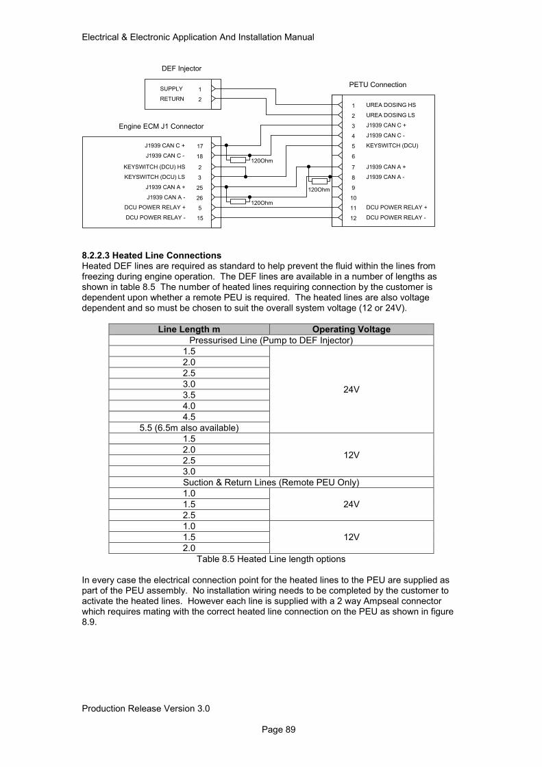
Electrical & Electronic Application And Installation Manual
Production Release Version 3.0 Page 89
8.2.2.3 Heated Line Connections Heated DEF lines are required as standard to help prevent the fluid within the lines from freezing during engine operation. The DEF lines are available in a number of lengths as shown in table 8.5 The number of heated lines requiring connection by the customer is dependent upon whether a remote PEU is required. The heated lines are also voltage dependent and so must be chosen to suit the overall system voltage (12 or 24V).
Line Length m Operating Voltage
Pressurised Line (Pump to DEF Injector)
1.5
24V
2.0
2.5
3.0
3.5
4.0
4.5
5.5 (6.5m also available)
1.5
12V 2.0
2.5
3.0
Suction & Return Lines (Remote PEU Only)
1.0
24V 1.5
2.5
1.0
12V 1.5
2.0
Table 8.5 Heated Line length options
In every case the electrical connection point for the heated lines to the PEU are supplied as part of the PEU assembly. No installation wiring needs to be completed by the customer to activate the heated lines. However each line is supplied with a 2 way Ampseal connector which requires mating with the correct heated line connection on the PEU as shown in figure 8.9.
26J1939 CAN A -
5DCU POWER RELAY +
15DCU POWER RELAY -
2KEYSWITCH (DCU) HS
Engine ECM J1 Connector
1 UREA DOSING HS
2 UREA DOSING LS
3 J1939 CAN C +
4 J1939 CAN C -
5 KEYSWITCH (DCU)
6
PETU Connection
7 J1939 CAN A +
8 J1939 CAN A -
9
10
11 DCU POWER RELAY +
12 DCU POWER RELAY -
1SUPPLY
2RETURN
DEF Injector
25J1939 CAN A +
3KEYSWITCH (DCU) LS
17J1939 CAN C +
18J1939 CAN C -
120Ohm
120Ohm
120Ohm
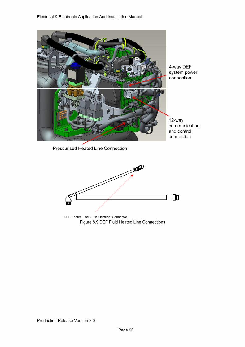
Electrical & Electronic Application And Installation Manual
Production Release Version 3.0 Page 90
Figure 8.9 DEF Fluid Heated Line Connections
DEF Heated Line 2 Pin Electrical Connector
Pressurised Heated Line Connection
12-way
communication
and control
connection
4-way DEF
system power
connection
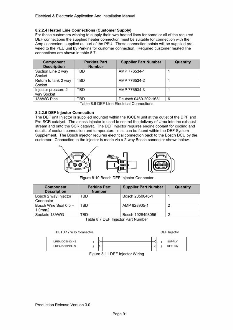
Electrical & Electronic Application And Installation Manual
Production Release Version 3.0 Page 91
8.2.2.4 Heated Line Connections (Customer Supply) For those customers wishing to supply their own heated lines for some or all of the required DEF connections the supplied heater connection must be suitable for connection with the Amp connectors supplied as part of the PEU. These connection points will be supplied pre-wired to the PEU unit by Perkins for customer connection. Required customer heated line connections are shown in table 8.7.
Component Description
Perkins Part Number
Supplier Part Number Quantity
Suction Line 2 way Socket
TBD AMP 776534-1 1
Return to tank 2 way Socket
TBD AMP 776534-2 1
Injector pressure 2 way Socket
TBD AMP 776534-3 1
18AWG Pins TBD Deutsch 0460-202-1631 6
Table 8.6 DEF Line Electrical Connections
8.2.2.5 DEF Injector Connection The DEF unit Injector is supplied mounted within the IGCEM unit at the outlet of the DPF and Pre-SCR catalyst. The airless injector is used to control the delivery of Urea into the exhaust stream and onto the SCR catalyst. The DEF injector requires engine coolant for cooling and details of coolant connection and temperature limits can be found within the DEF System Supplement. The Bosch injector requires electrical connection back to the Bosch DCU by the customer. Connection to the injector is made via a 2-way Bosch connector shown below.
Figure 8.10 Bosch DEF Injector Connector
Component Description
Perkins Part Number
Supplier Part Number Quantity
Bosch 2 way Injector Connector
TBD Bosch 2050046-1 1
Bosch Wire Seal 0.5 – 1.0mm2
TBD AMP 828905-1 2
Sockets 18AWG TBD Bosch 1928498056 2
Table 8.7 DEF Injector Part Number
Figure 8.11 DEF Injector Wiring
1 SUPPLY
2 RETURN
DEF Injector
1UREA DOSING HS
2UREA DOSING LS
PETU 12 Way Connector
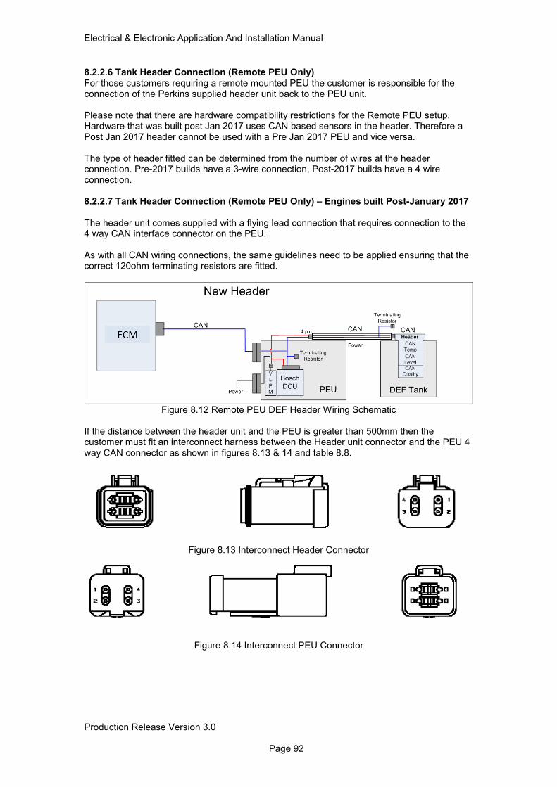
Electrical & Electronic Application And Installation Manual
Production Release Version 3.0 Page 92
8.2.2.6 Tank Header Connection (Remote PEU Only) For those customers requiring a remote mounted PEU the customer is responsible for the connection of the Perkins supplied header unit back to the PEU unit. Please note that there are hardware compatibility restrictions for the Remote PEU setup. Hardware that was built post Jan 2017 uses CAN based sensors in the header. Therefore a Post Jan 2017 header cannot be used with a Pre Jan 2017 PEU and vice versa. The type of header fitted can be determined from the number of wires at the header connection. Pre-2017 builds have a 3-wire connection, Post-2017 builds have a 4 wire connection. 8.2.2.7 Tank Header Connection (Remote PEU Only) – Engines built Post-January 2017 The header unit comes supplied with a flying lead connection that requires connection to the 4 way CAN interface connector on the PEU. As with all CAN wiring connections, the same guidelines need to be applied ensuring that the correct 120ohm terminating resistors are fitted.
Figure 8.12 Remote PEU DEF Header Wiring Schematic
If the distance between the header unit and the PEU is greater than 500mm then the customer must fit an interconnect harness between the Header unit connector and the PEU 4 way CAN connector as shown in figures 8.13 & 14 and table 8.8.
Figure 8.13 Interconnect Header Connector
Figure 8.14 Interconnect PEU Connector
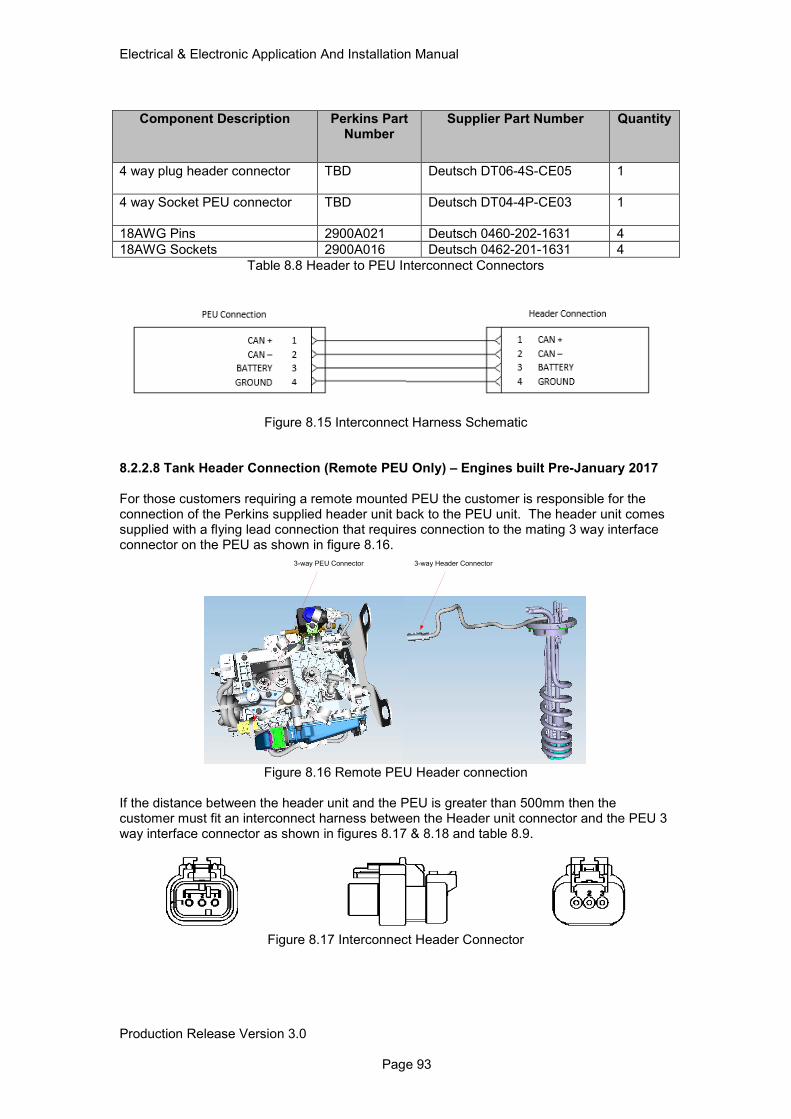
Electrical & Electronic Application And Installation Manual
Production Release Version 3.0 Page 93
Component Description Perkins Part Number
Supplier Part Number Quantity
4 way plug header connector TBD
Deutsch DT06-4S-CE05 1
4 way Socket PEU connector TBD
Deutsch DT04-4P-CE03 1
18AWG Pins 2900A021 Deutsch 0460-202-1631 4
18AWG Sockets 2900A016 Deutsch 0462-201-1631 4
Table 8.8 Header to PEU Interconnect Connectors
Figure 8.15 Interconnect Harness Schematic
8.2.2.8 Tank Header Connection (Remote PEU Only) – Engines built Pre-January 2017
For those customers requiring a remote mounted PEU the customer is responsible for the connection of the Perkins supplied header unit back to the PEU unit. The header unit comes supplied with a flying lead connection that requires connection to the mating 3 way interface connector on the PEU as shown in figure 8.16.
Figure 8.16 Remote PEU Header connection
If the distance between the header unit and the PEU is greater than 500mm then the customer must fit an interconnect harness between the Header unit connector and the PEU 3 way interface connector as shown in figures 8.17 & 8.18 and table 8.9.
Figure 8.17 Interconnect Header Connector
3-way Header Connector3-way PEU Connector
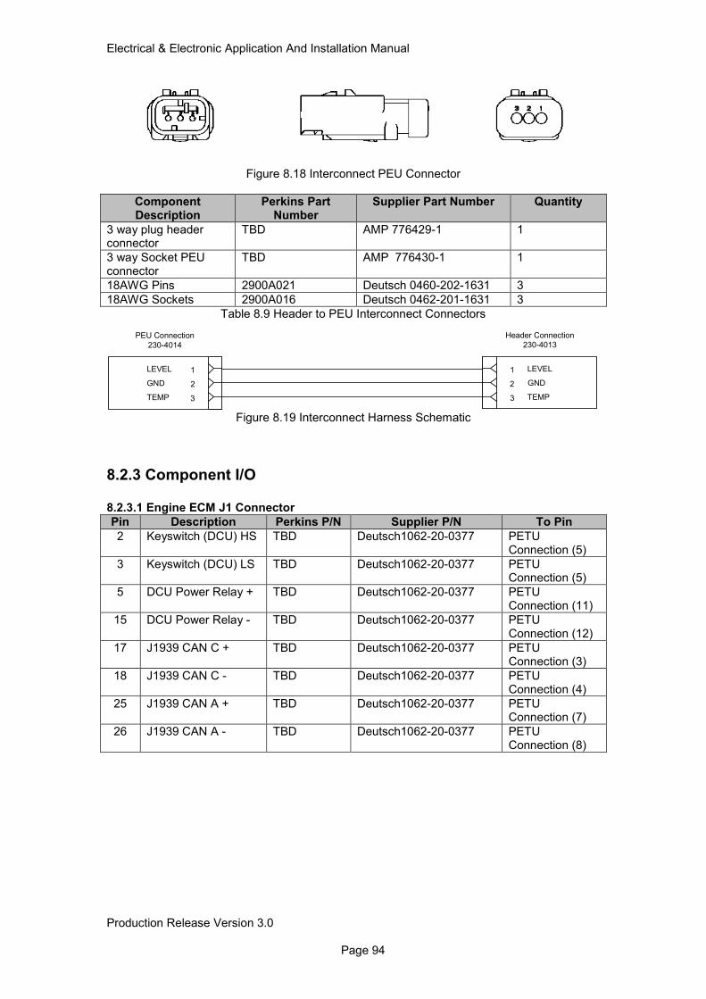
Electrical & Electronic Application And Installation Manual
Production Release Version 3.0 Page 94
Figure 8.18 Interconnect PEU Connector
Component Description
Perkins Part Number
Supplier Part Number Quantity
3 way plug header connector
TBD AMP 776429-1 1
3 way Socket PEU connector
TBD AMP 776430-1 1
18AWG Pins 2900A021 Deutsch 0460-202-1631 3
18AWG Sockets 2900A016 Deutsch 0462-201-1631 3
Table 8.9 Header to PEU Interconnect Connectors
Figure 8.19 Interconnect Harness Schematic
8.2.3 Component I/O
8.2.3.1 Engine ECM J1 Connector
Pin Description Perkins P/N Supplier P/N To Pin
2 Keyswitch (DCU) HS TBD Deutsch1062-20-0377 PETU Connection (5)
3 Keyswitch (DCU) LS TBD Deutsch1062-20-0377 PETU Connection (5)
5 DCU Power Relay + TBD Deutsch1062-20-0377 PETU Connection (11)
15 DCU Power Relay - TBD Deutsch1062-20-0377 PETU Connection (12)
17 J1939 CAN C + TBD Deutsch1062-20-0377 PETU Connection (3)
18 J1939 CAN C - TBD Deutsch1062-20-0377 PETU Connection (4)
25 J1939 CAN A + TBD Deutsch1062-20-0377 PETU Connection (7)
26 J1939 CAN A - TBD Deutsch1062-20-0377 PETU Connection (8)
1 LEVEL
2 GND
3 TEMP
Header Connection
230-4013
1LEVEL
2GND
3TEMP
PEU Connection
230-4014
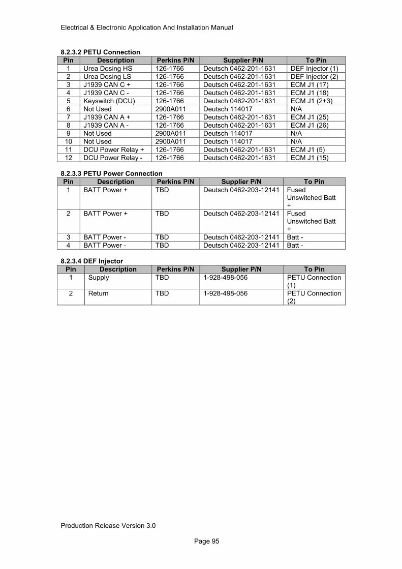
Electrical & Electronic Application And Installation Manual
Production Release Version 3.0 Page 95
8.2.3.2 PETU Connection
Pin Description Perkins P/N Supplier P/N To Pin
1 Urea Dosing HS 126-1766 Deutsch 0462-201-1631 DEF Injector (1)
2 Urea Dosing LS 126-1766 Deutsch 0462-201-1631 DEF Injector (2)
3 J1939 CAN C + 126-1766 Deutsch 0462-201-1631 ECM J1 (17)
4 J1939 CAN C - 126-1766 Deutsch 0462-201-1631 ECM J1 (18)
5 Keyswitch (DCU) 126-1766 Deutsch 0462-201-1631 ECM J1 (2+3)
6 Not Used 2900A011 Deutsch 114017 N/A
7 J1939 CAN A + 126-1766 Deutsch 0462-201-1631 ECM J1 (25)
8 J1939 CAN A - 126-1766 Deutsch 0462-201-1631 ECM J1 (26)
9 Not Used 2900A011 Deutsch 114017 N/A
10 Not Used 2900A011 Deutsch 114017 N/A
11 DCU Power Relay + 126-1766 Deutsch 0462-201-1631 ECM J1 (5)
12 DCU Power Relay - 126-1766 Deutsch 0462-201-1631 ECM J1 (15)
8.2.3.3 PETU Power Connection
Pin Description Perkins P/N Supplier P/N To Pin
1 BATT Power + TBD Deutsch 0462-203-12141 Fused Unswitched Batt +
2 BATT Power + TBD Deutsch 0462-203-12141 Fused Unswitched Batt +
3 BATT Power - TBD Deutsch 0462-203-12141 Batt -
4 BATT Power - TBD Deutsch 0462-203-12141 Batt -
8.2.3.4 DEF Injector
Pin Description Perkins P/N Supplier P/N To Pin
1 Supply TBD 1-928-498-056 PETU Connection (1)
2 Return TBD 1-928-498-056 PETU Connection (2)
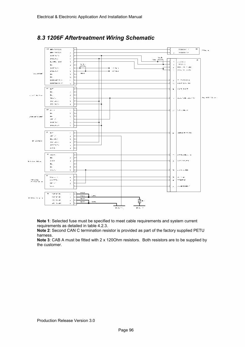
Electrical & Electronic Application And Installation Manual
Production Release Version 3.0 Page 96
8.3 1206F Aftertreatment Wiring Schematic
Note 1: Selected fuse must be specified to meet cable requirements and system current requirements as detailed in table 4.2.3. Note 2: Second CAN C termination resistor is provided as part of the factory supplied PETU harness. Note 3: CAB A must be fitted with 2 x 120Ohm resistors. Both resistors are to be supplied by the customer.
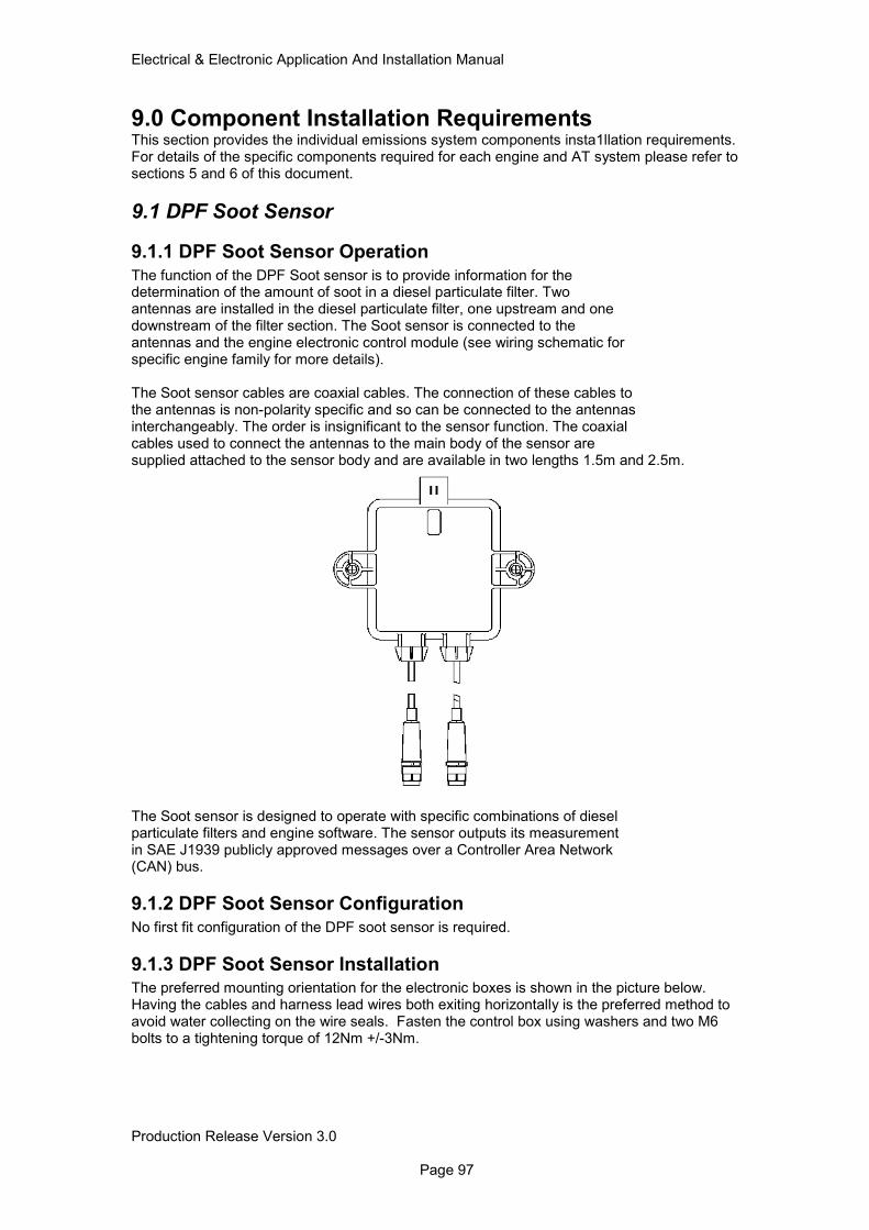
Electrical & Electronic Application And Installation Manual
Production Release Version 3.0 Page 97
9.0 Component Installation Requirements This section provides the individual emissions system components insta1llation requirements. For details of the specific components required for each engine and AT system please refer to sections 5 and 6 of this document.
9.1 DPF Soot Sensor
9.1.1 DPF Soot Sensor Operation
The function of the DPF Soot sensor is to provide information for the determination of the amount of soot in a diesel particulate filter. Two antennas are installed in the diesel particulate filter, one upstream and one downstream of the filter section. The Soot sensor is connected to the antennas and the engine electronic control module (see wiring schematic for specific engine family for more details). The Soot sensor cables are coaxial cables. The connection of these cables to the antennas is non-polarity specific and so can be connected to the antennas interchangeably. The order is insignificant to the sensor function. The coaxial cables used to connect the antennas to the main body of the sensor are supplied attached to the sensor body and are available in two lengths 1.5m and 2.5m.
The Soot sensor is designed to operate with specific combinations of diesel particulate filters and engine software. The sensor outputs its measurement in SAE J1939 publicly approved messages over a Controller Area Network (CAN) bus.
9.1.2 DPF Soot Sensor Configuration
No first fit configuration of the DPF soot sensor is required.
9.1.3 DPF Soot Sensor Installation The preferred mounting orientation for the electronic boxes is shown in the picture below. Having the cables and harness lead wires both exiting horizontally is the preferred method to avoid water collecting on the wire seals. Fasten the control box using washers and two M6 bolts to a tightening torque of 12Nm +/-3Nm.
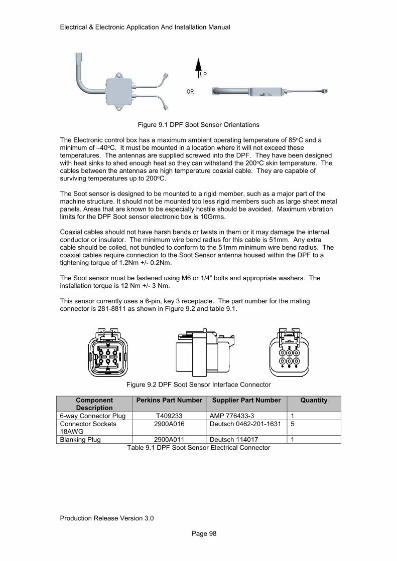
Electrical & Electronic Application And Installation Manual
Production Release Version 3.0 Page 98
Figure 9.1 DPF Soot Sensor Orientations
The Electronic control box has a maximum ambient operating temperature of 85oC and a minimum of –40oC. It must be mounted in a location where it will not exceed these temperatures. The antennas are supplied screwed into the DPF. They have been designed with heat sinks to shed enough heat so they can withstand the 200oC skin temperature. The cables between the antennas are high temperature coaxial cable. They are capable of surviving temperatures up to 200oC. The Soot sensor is designed to be mounted to a rigid member, such as a major part of the machine structure. It should not be mounted too less rigid members such as large sheet metal panels. Areas that are known to be especially hostile should be avoided. Maximum vibration limits for the DPF Soot sensor electronic box is 10Grms. Coaxial cables should not have harsh bends or twists in them or it may damage the internal conductor or insulator. The minimum wire bend radius for this cable is 51mm. Any extra cable should be coiled, not bundled to conform to the 51mm minimum wire bend radius. The coaxial cables require connection to the Soot Sensor antenna housed within the DPF to a tightening torque of 1.2Nm +/- 0.2Nm. The Soot sensor must be fastened using M6 or 1/4” bolts and appropriate washers. The installation torque is 12 Nm +/- 3 Nm. This sensor currently uses a 6-pin, key 3 receptacle. The part number for the mating connector is 281-8811 as shown in Figure 9.2 and table 9.1.
Figure 9.2 DPF Soot Sensor Interface Connector
Component Description
Perkins Part Number Supplier Part Number Quantity
6-way Connector Plug T409233 AMP 776433-3 1
Connector Sockets 18AWG
2900A016 Deutsch 0462-201-1631 5
Blanking Plug 2900A011 Deutsch 114017 1
Table 9.1 DPF Soot Sensor Electrical Connector
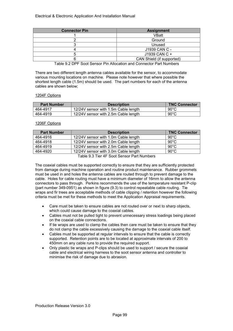
Electrical & Electronic Application And Installation Manual
Production Release Version 3.0 Page 99
Connector Pin Assignment
1 VBatt
2 Ground
3 Unused
4 J1939 CAN C -
5 J1939 CAN C +
6 CAN Shield (if supported)
Table 9.2 DPF Soot Sensor Pin Allocation and Connector Part Numbers There are two different length antenna cables available for the sensor, to accommodate various mounting locations on machine. Please note however that where possible the shortest length cable (1.5m) should be used. The part numbers for each of the antenna cables are shown below; 1204F Options
Part Number Description TNC Connector
464-4917 12/24V sensor with 1.5m Cable length 90°C
464-4919 12/24V sensor with 2.5m Cable length 90°C
1206F Options
Part Number Description TNC Connector
464-4916 12/24V sensor with 1.0m Cable length 90°C
464-4918 12/24V sensor with 2.0m Cable length 90°C
464-4919 12/24V sensor with 2.5m Cable length 90°C
464-4920 12/24V sensor with 3.0m Cable length 90°C
Table 9.3 Tier 4F Soot Sensor Part Numbers The coaxial cables must be supported correctly to ensure that they are sufficiently protected from damage during machine operation and routine product maintenance. Rubber grommets must be used in and holes the antenna cables are routed through to prevent damage to the cable. Holes for cable routing must have a minimum diameter of 16mm to allow the antenna connectors to pass through. Perkins recommends the use of the temperature resistant P-clip (part number 349-0951) as shown in figure (9.3) to control repeatable cable routing. Tie wraps and fir trees are acceptable methods of cable clipping / retention however the following criteria must be met for these methods to meet the Application Appraisal requirements.
• Care must be taken to ensure cables are not routed over or next to sharp objects, which could cause damage to the coaxial cables.
• Cables must not be pulled tight to prevent unnecessary stress loadings being placed on the coaxial cable connections.
• If tie wraps are used to clamp the cables then care must be taken to ensure that they do not clamp the cable excessively causing the damage to the coaxial cable itself.
• Cables must be supported at regular intervals to ensure that the cable is correctly supported. Retention points are to be located at approximate intervals of 200 to 450mm on any cable runs to provide the required support.
• Only plastic tie wraps and P-clips should be used to support / secure the coaxial cable and electrical wiring harness to the soot sensor antenna and controller to minimise the risk of damage due to abrasion.
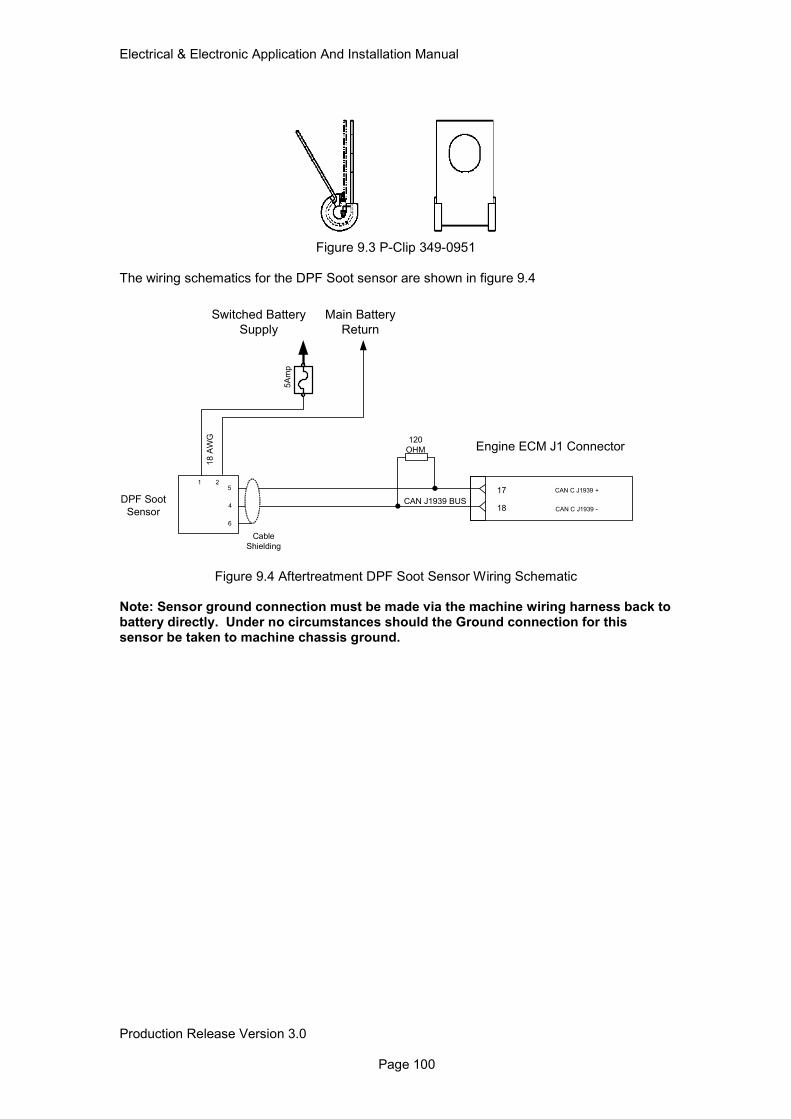
Electrical & Electronic Application And Installation Manual
Production Release Version 3.0 Page 100
Figure 9.3 P-Clip 349-0951
The wiring schematics for the DPF Soot sensor are shown in figure 9.4
Figure 9.4 Aftertreatment DPF Soot Sensor Wiring Schematic
Note: Sensor ground connection must be made via the machine wiring harness back to battery directly. Under no circumstances should the Ground connection for this sensor be taken to machine chassis ground.
CAN C J1939 +
CAN C J1939 -
1 2
4
5A
mp
120
OHM
CAN J1939 BUSDPF Soot
Sensor
Switched Battery
Supply
18 A
WG
5
Cable
Shielding
17
18
Main Battery
Return
Engine ECM J1 Connector
6
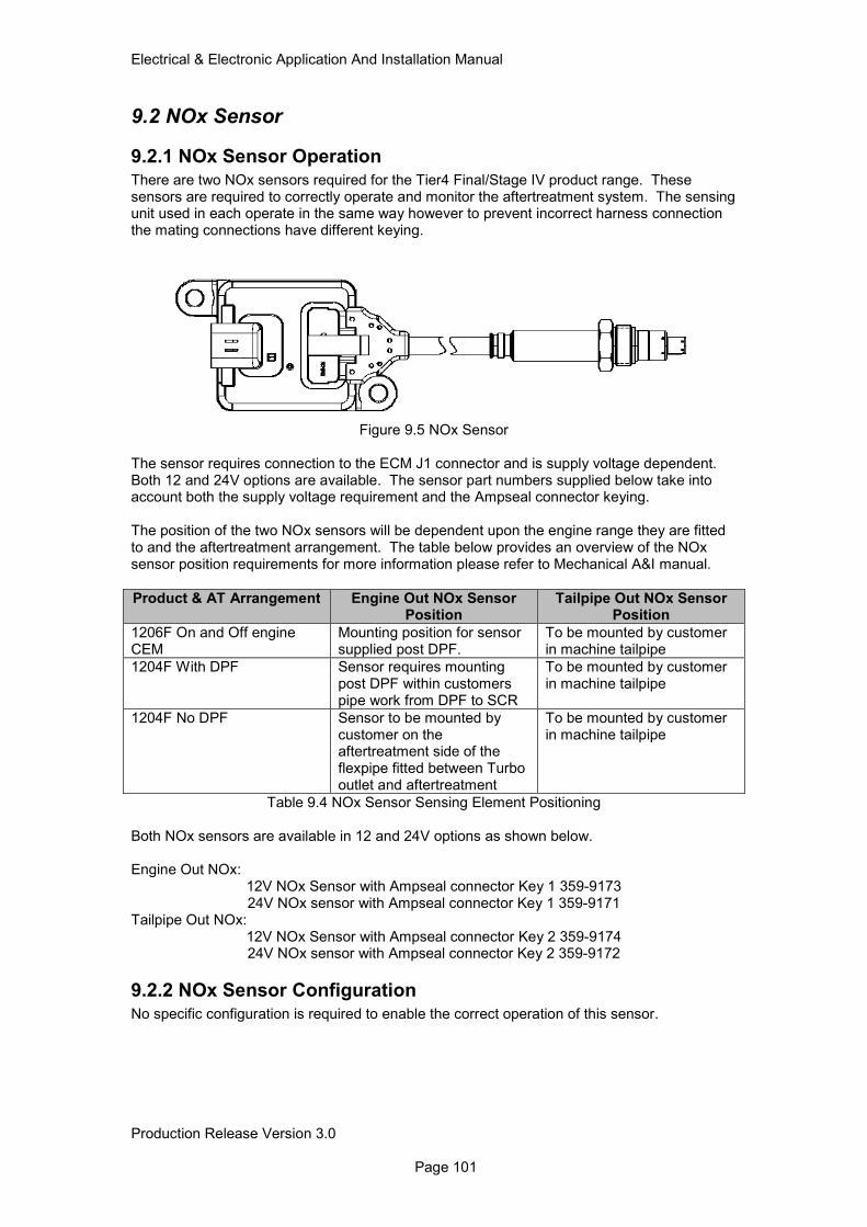
Electrical & Electronic Application And Installation Manual
Production Release Version 3.0 Page 101
9.2 NOx Sensor
9.2.1 NOx Sensor Operation
There are two NOx sensors required for the Tier4 Final/Stage IV product range. These sensors are required to correctly operate and monitor the aftertreatment system. The sensing unit used in each operate in the same way however to prevent incorrect harness connection the mating connections have different keying.
Figure 9.5 NOx Sensor The sensor requires connection to the ECM J1 connector and is supply voltage dependent. Both 12 and 24V options are available. The sensor part numbers supplied below take into account both the supply voltage requirement and the Ampseal connector keying. The position of the two NOx sensors will be dependent upon the engine range they are fitted to and the aftertreatment arrangement. The table below provides an overview of the NOx sensor position requirements for more information please refer to Mechanical A&I manual.
Product & AT Arrangement Engine Out NOx Sensor Position
Tailpipe Out NOx Sensor Position
1206F On and Off engine CEM
Mounting position for sensor supplied post DPF.
To be mounted by customer in machine tailpipe
1204F With DPF Sensor requires mounting post DPF within customers pipe work from DPF to SCR
To be mounted by customer in machine tailpipe
1204F No DPF Sensor to be mounted by customer on the aftertreatment side of the flexpipe fitted between Turbo outlet and aftertreatment
To be mounted by customer in machine tailpipe
Table 9.4 NOx Sensor Sensing Element Positioning Both NOx sensors are available in 12 and 24V options as shown below. Engine Out NOx:
12V NOx Sensor with Ampseal connector Key 1 359-9173 24V NOx sensor with Ampseal connector Key 1 359-9171
Tailpipe Out NOx: 12V NOx Sensor with Ampseal connector Key 2 359-9174 24V NOx sensor with Ampseal connector Key 2 359-9172
9.2.2 NOx Sensor Configuration
No specific configuration is required to enable the correct operation of this sensor.
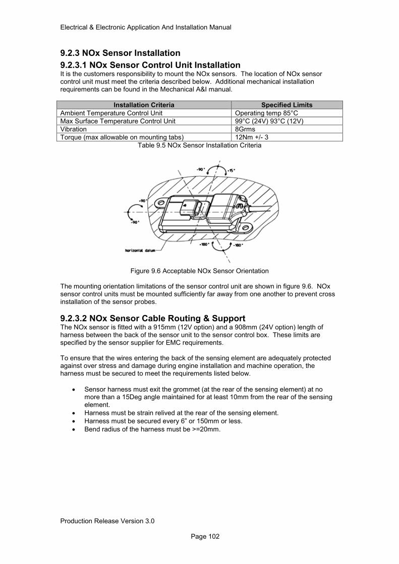
Electrical & Electronic Application And Installation Manual
Production Release Version 3.0 Page 102
9.2.3 NOx Sensor Installation
9.2.3.1 NOx Sensor Control Unit Installation It is the customers responsibility to mount the NOx sensors. The location of NOx sensor control unit must meet the criteria described below. Additional mechanical installation requirements can be found in the Mechanical A&I manual.
Installation Criteria Specified Limits
Ambient Temperature Control Unit Operating temp 85°C
Max Surface Temperature Control Unit 99°C (24V) 93°C (12V)
Vibration 8Grms
Torque (max allowable on mounting tabs) 12Nm +/- 3
Table 9.5 NOx Sensor Installation Criteria
Figure 9.6 Acceptable NOx Sensor Orientation
The mounting orientation limitations of the sensor control unit are shown in figure 9.6. NOx sensor control units must be mounted sufficiently far away from one another to prevent cross installation of the sensor probes.
9.2.3.2 NOx Sensor Cable Routing & Support The NOx sensor is fitted with a 915mm (12V option) and a 908mm (24V option) length of harness between the back of the sensor unit to the sensor control box. These limits are specified by the sensor supplier for EMC requirements. To ensure that the wires entering the back of the sensing element are adequately protected against over stress and damage during engine installation and machine operation, the harness must be secured to meet the requirements listed below.
• Sensor harness must exit the grommet (at the rear of the sensing element) at no more than a 15Deg angle maintained for at least 10mm from the rear of the sensing element.
• Harness must be strain relived at the rear of the sensing element.
• Harness must be secured every 6” or 150mm or less.
• Bend radius of the harness must be >=20mm.
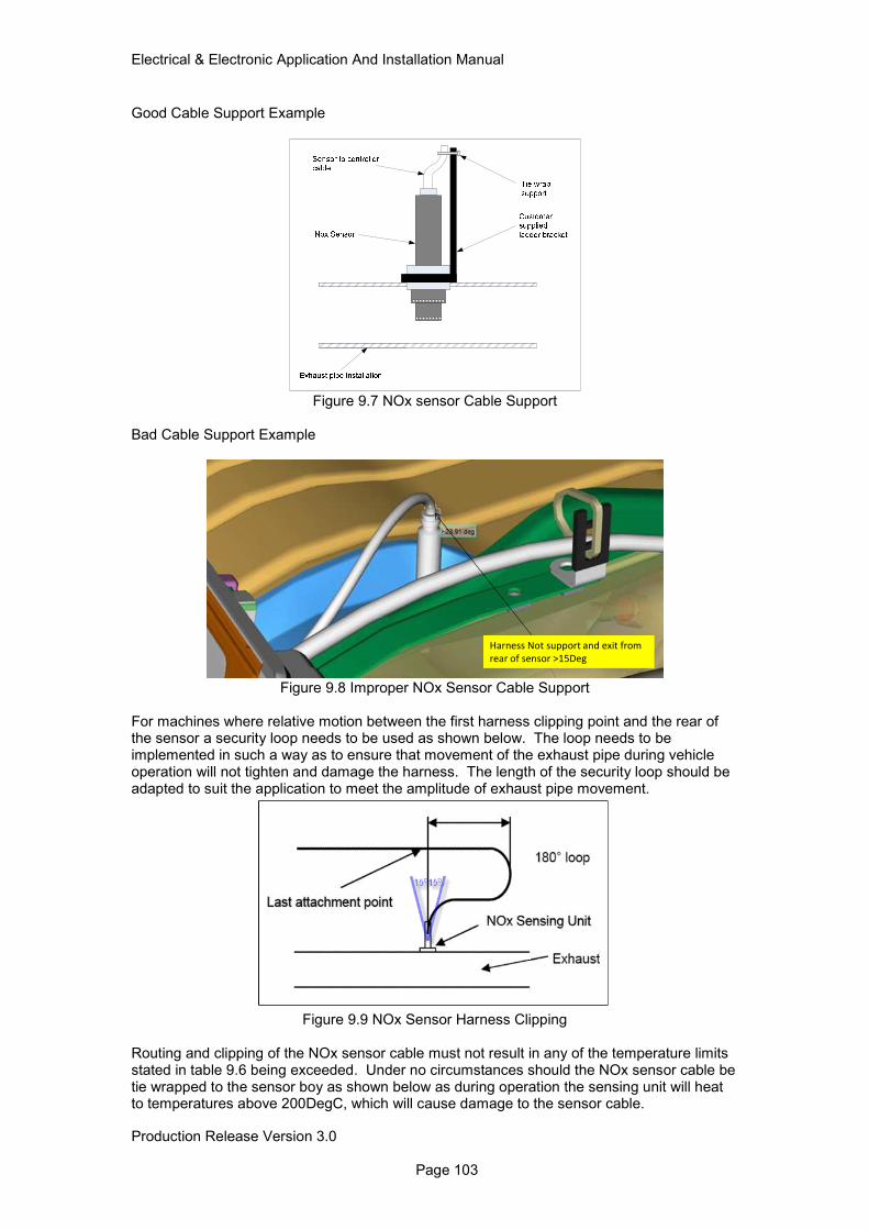
Electrical & Electronic Application And Installation Manual
Production Release Version 3.0 Page 103
Good Cable Support Example
Figure 9.7 NOx sensor Cable Support
Bad Cable Support Example
Harness Not support and exit from
rear of sensor >15Deg
Figure 9.8 Improper NOx Sensor Cable Support
For machines where relative motion between the first harness clipping point and the rear of the sensor a security loop needs to be used as shown below. The loop needs to be implemented in such a way as to ensure that movement of the exhaust pipe during vehicle operation will not tighten and damage the harness. The length of the security loop should be adapted to suit the application to meet the amplitude of exhaust pipe movement.
Figure 9.9 NOx Sensor Harness Clipping
Routing and clipping of the NOx sensor cable must not result in any of the temperature limits stated in table 9.6 being exceeded. Under no circumstances should the NOx sensor cable be tie wrapped to the sensor boy as shown below as during operation the sensing unit will heat to temperatures above 200DegC, which will cause damage to the sensor cable.
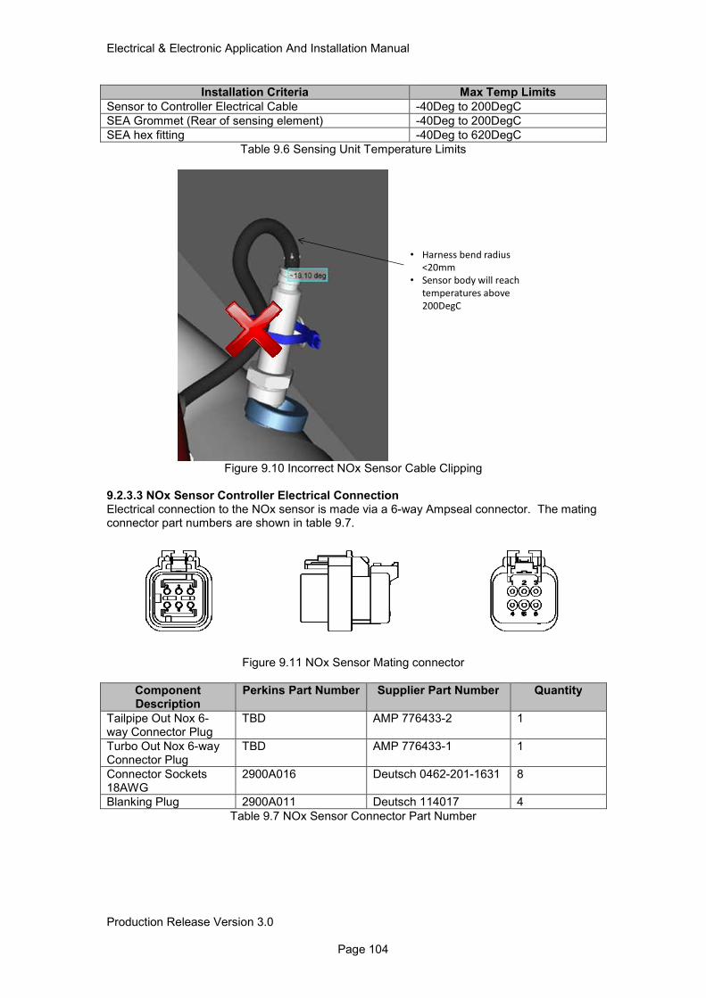
Electrical & Electronic Application And Installation Manual
Production Release Version 3.0 Page 104
Installation Criteria Max Temp Limits
Sensor to Controller Electrical Cable -40Deg to 200DegC
SEA Grommet (Rear of sensing element) -40Deg to 200DegC
SEA hex fitting -40Deg to 620DegC
Table 9.6 Sensing Unit Temperature Limits
• Harness bend radius
<20mm
• Sensor body will reach
temperatures above
200DegC
Figure 9.10 Incorrect NOx Sensor Cable Clipping
9.2.3.3 NOx Sensor Controller Electrical Connection Electrical connection to the NOx sensor is made via a 6-way Ampseal connector. The mating connector part numbers are shown in table 9.7.
Figure 9.11 NOx Sensor Mating connector
Component Description
Perkins Part Number Supplier Part Number Quantity
Tailpipe Out Nox 6-way Connector Plug
TBD AMP 776433-2 1
Turbo Out Nox 6-way Connector Plug
TBD AMP 776433-1 1
Connector Sockets 18AWG
2900A016 Deutsch 0462-201-1631 8
Blanking Plug 2900A011 Deutsch 114017 4
Table 9.7 NOx Sensor Connector Part Number
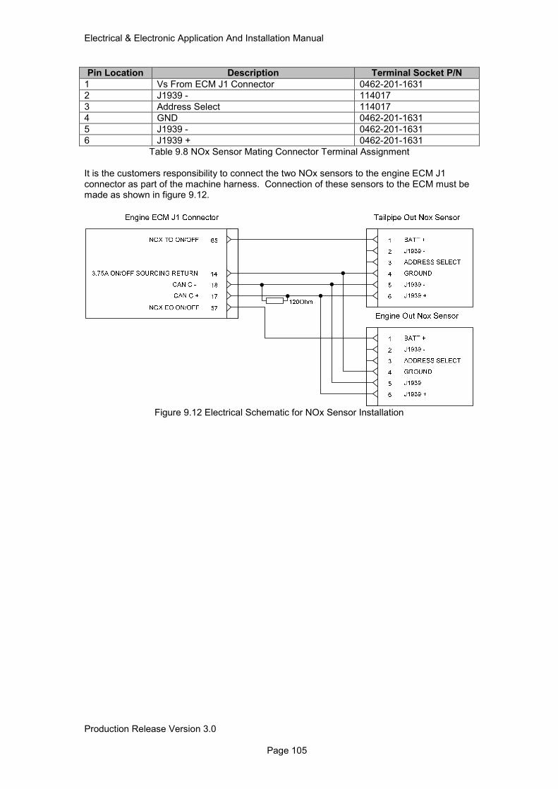
Electrical & Electronic Application And Installation Manual
Production Release Version 3.0 Page 105
Pin Location Description Terminal Socket P/N
1 Vs From ECM J1 Connector 0462-201-1631
2 J1939 - 114017
3 Address Select 114017
4 GND 0462-201-1631
5 J1939 - 0462-201-1631
6 J1939 + 0462-201-1631
Table 9.8 NOx Sensor Mating Connector Terminal Assignment
It is the customers responsibility to connect the two NOx sensors to the engine ECM J1 connector as part of the machine harness. Connection of these sensors to the ECM must be made as shown in figure 9.12.
Figure 9.12 Electrical Schematic for NOx Sensor Installation
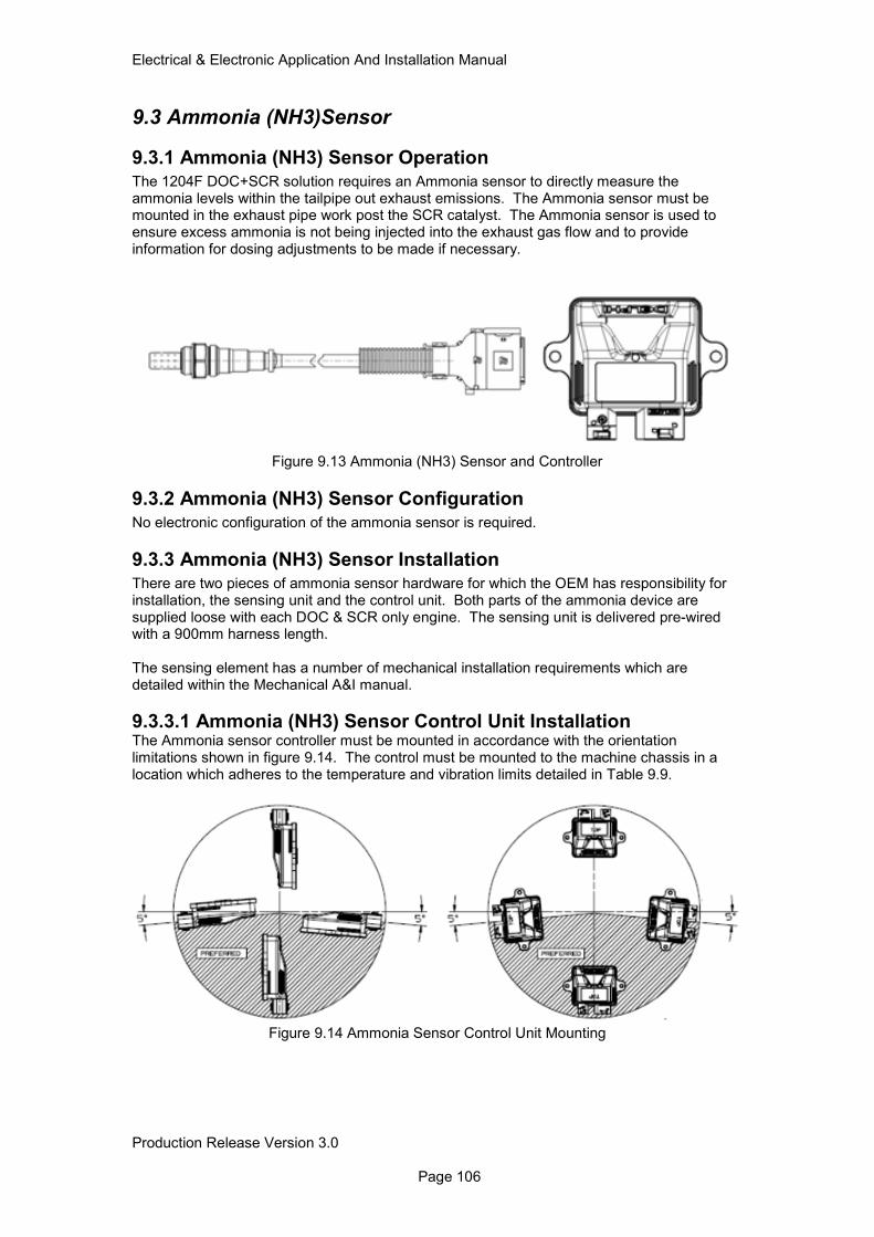
Electrical & Electronic Application And Installation Manual
Production Release Version 3.0 Page 106
9.3 Ammonia (NH3)Sensor
9.3.1 Ammonia (NH3) Sensor Operation
The 1204F DOC+SCR solution requires an Ammonia sensor to directly measure the ammonia levels within the tailpipe out exhaust emissions. The Ammonia sensor must be mounted in the exhaust pipe work post the SCR catalyst. The Ammonia sensor is used to ensure excess ammonia is not being injected into the exhaust gas flow and to provide information for dosing adjustments to be made if necessary.
Figure 9.13 Ammonia (NH3) Sensor and Controller
9.3.2 Ammonia (NH3) Sensor Configuration
No electronic configuration of the ammonia sensor is required.
9.3.3 Ammonia (NH3) Sensor Installation
There are two pieces of ammonia sensor hardware for which the OEM has responsibility for installation, the sensing unit and the control unit. Both parts of the ammonia device are supplied loose with each DOC & SCR only engine. The sensing unit is delivered pre-wired with a 900mm harness length. The sensing element has a number of mechanical installation requirements which are detailed within the Mechanical A&I manual.
9.3.3.1 Ammonia (NH3) Sensor Control Unit Installation The Ammonia sensor controller must be mounted in accordance with the orientation limitations shown in figure 9.14. The control must be mounted to the machine chassis in a location which adheres to the temperature and vibration limits detailed in Table 9.9.
Figure 9.14 Ammonia Sensor Control Unit Mounting
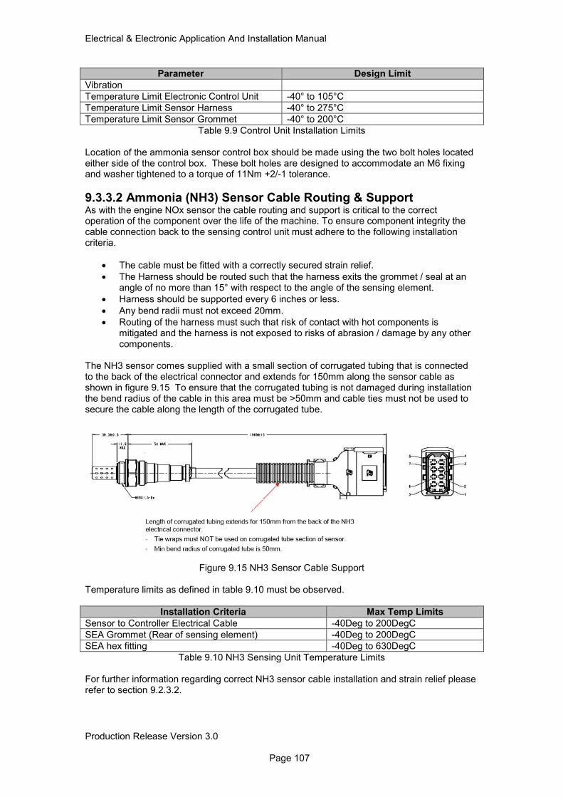
Electrical & Electronic Application And Installation Manual
Production Release Version 3.0 Page 107
Parameter Design Limit
Vibration
Temperature Limit Electronic Control Unit -40° to 105°C
Temperature Limit Sensor Harness -40° to 275°C
Temperature Limit Sensor Grommet -40° to 200°C
Table 9.9 Control Unit Installation Limits Location of the ammonia sensor control box should be made using the two bolt holes located either side of the control box. These bolt holes are designed to accommodate an M6 fixing and washer tightened to a torque of 11Nm +2/-1 tolerance.
9.3.3.2 Ammonia (NH3) Sensor Cable Routing & Support As with the engine NOx sensor the cable routing and support is critical to the correct operation of the component over the life of the machine. To ensure component integrity the cable connection back to the sensing control unit must adhere to the following installation criteria.
• The cable must be fitted with a correctly secured strain relief.
• The Harness should be routed such that the harness exits the grommet / seal at an angle of no more than 15° with respect to the angle of the sensing element.
• Harness should be supported every 6 inches or less.
• Any bend radii must not exceed 20mm.
• Routing of the harness must such that risk of contact with hot components is mitigated and the harness is not exposed to risks of abrasion / damage by any other components.
The NH3 sensor comes supplied with a small section of corrugated tubing that is connected to the back of the electrical connector and extends for 150mm along the sensor cable as shown in figure 9.15 To ensure that the corrugated tubing is not damaged during installation the bend radius of the cable in this area must be >50mm and cable ties must not be used to secure the cable along the length of the corrugated tube.
Figure 9.15 NH3 Sensor Cable Support
Temperature limits as defined in table 9.10 must be observed.
Installation Criteria Max Temp Limits
Sensor to Controller Electrical Cable -40Deg to 200DegC
SEA Grommet (Rear of sensing element) -40Deg to 200DegC
SEA hex fitting -40Deg to 630DegC
Table 9.10 NH3 Sensing Unit Temperature Limits For further information regarding correct NH3 sensor cable installation and strain relief please refer to section 9.2.3.2.
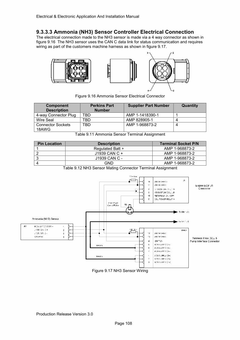
Electrical & Electronic Application And Installation Manual
Production Release Version 3.0 Page 108
9.3.3.3 Ammonia (NH3) Sensor Controller Electrical Connection The electrical connection made to the NH3 sensor is made via a 4 way connector as shown in figure 9.16 The NH3 sensor uses the CAN C data link for status communication and requires wiring as part of the customers machine harness as shown in figure 9.17.
Figure 9.16 Ammonia Sensor Electrical Connector
Component Description
Perkins Part Number
Supplier Part Number Quantity
4-way Connector Plug TBD AMP 1-1418390-1 1
Wire Seal TBD AMP 828905-1 4
Connector Sockets 18AWG
TBD AMP 1-968873-2 4
Table 9.11 Ammonia Sensor Terminal Assignment
Pin Location Description Terminal Socket P/N
1 Regulated Batt + AMP 1-968873-2
2 J1939 CAN C + AMP 1-968873-2
3 J1939 CAN C - AMP 1-968873-2
4 GND AMP 1-968873-2
Table 9.12 NH3 Sensor Mating Connector Terminal Assignment
Figure 9.17 NH3 Sensor Wiring
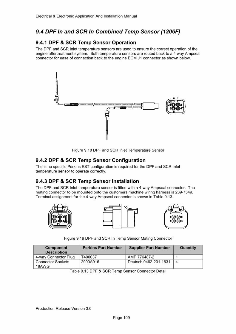
Electrical & Electronic Application And Installation Manual
Production Release Version 3.0 Page 109
9.4 DPF In and SCR In Combined Temp Sensor (1206F)
9.4.1 DPF & SCR Temp Sensor Operation
The DPF and SCR Inlet temperature sensors are used to ensure the correct operation of the engine aftertreatment system. Both temperature sensors are routed back to a 4 way Ampseal connector for ease of connection back to the engine ECM J1 connector as shown below.
Figure 9.18 DPF and SCR Inlet Temperature Sensor
9.4.2 DPF & SCR Temp Sensor Configuration The is no specific Perkins EST configuration is required for the DPF and SCR Inlet temperature sensor to operate correctly.
9.4.3 DPF & SCR Temp Sensor Installation The DPF and SCR Inlet temperature sensor is fitted with a 4-way Ampseal connector. The mating connector to be mounted onto the customers machine wiring harness is 239-7349. Terminal assignment for the 4-way Ampseal connector is shown in Table 9.13.
Figure 9.19 DPF and SCR In Temp Sensor Mating Connector
Component Description
Perkins Part Number Supplier Part Number Quantity
4-way Connector Plug T400037 AMP 776487-2 1
Connector Sockets 18AWG
2900A016 Deutsch 0462-201-1631 4
Table 9.13 DPF & SCR Temp Sensor Connector Detail
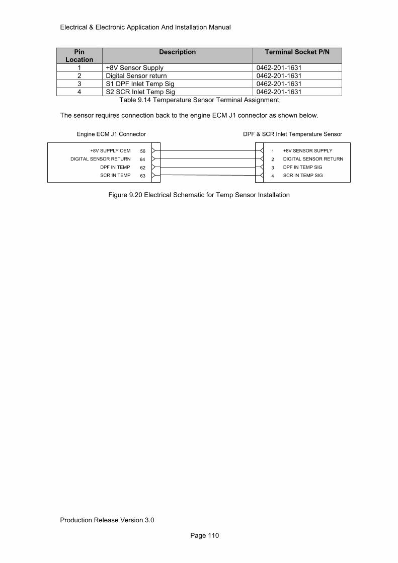
Electrical & Electronic Application And Installation Manual
Production Release Version 3.0 Page 110
Pin Location
Description Terminal Socket P/N
1 +8V Sensor Supply 0462-201-1631
2 Digital Sensor return 0462-201-1631
3 S1 DPF Inlet Temp Sig 0462-201-1631
4 S2 SCR Inlet Temp Sig 0462-201-1631
Table 9.14 Temperature Sensor Terminal Assignment The sensor requires connection back to the engine ECM J1 connector as shown below.
Figure 9.20 Electrical Schematic for Temp Sensor Installation
1 +8V SENSOR SUPPLY
2 DIGITAL SENSOR RETURN
3 DPF IN TEMP SIG
4 SCR IN TEMP SIG
DPF & SCR Inlet Temperature Sensor
64DIGITAL SENSOR RETURN
62DPF IN TEMP
63SCR IN TEMP
56+8V SUPPLY OEM
Engine ECM J1 Connector
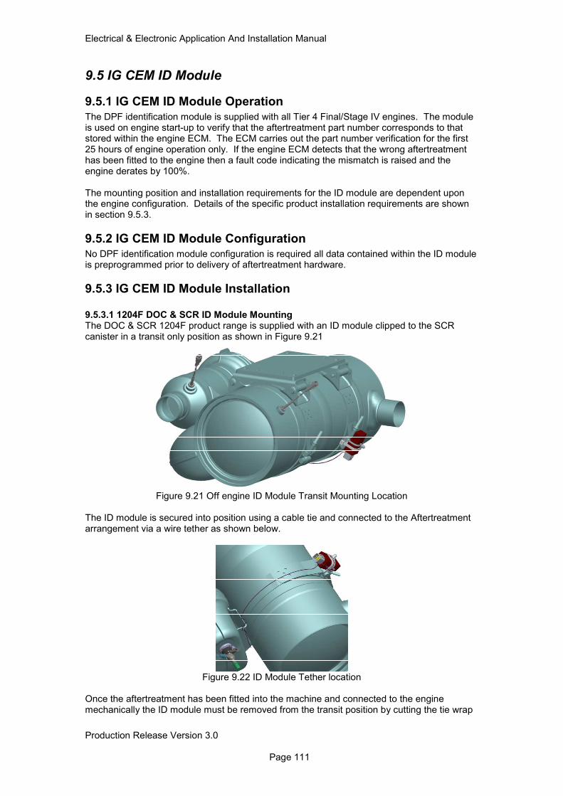
Electrical & Electronic Application And Installation Manual
Production Release Version 3.0 Page 111
9.5 IG CEM ID Module
9.5.1 IG CEM ID Module Operation
The DPF identification module is supplied with all Tier 4 Final/Stage IV engines. The module is used on engine start-up to verify that the aftertreatment part number corresponds to that stored within the engine ECM. The ECM carries out the part number verification for the first 25 hours of engine operation only. If the engine ECM detects that the wrong aftertreatment has been fitted to the engine then a fault code indicating the mismatch is raised and the engine derates by 100%. The mounting position and installation requirements for the ID module are dependent upon the engine configuration. Details of the specific product installation requirements are shown in section 9.5.3.
9.5.2 IG CEM ID Module Configuration
No DPF identification module configuration is required all data contained within the ID module is preprogrammed prior to delivery of aftertreatment hardware.
9.5.3 IG CEM ID Module Installation
9.5.3.1 1204F DOC & SCR ID Module Mounting The DOC & SCR 1204F product range is supplied with an ID module clipped to the SCR canister in a transit only position as shown in Figure 9.21
Figure 9.21 Off engine ID Module Transit Mounting Location
The ID module is secured into position using a cable tie and connected to the Aftertreatment arrangement via a wire tether as shown below.
Figure 9.22 ID Module Tether location
Once the aftertreatment has been fitted into the machine and connected to the engine mechanically the ID module must be removed from the transit position by cutting the tie wrap
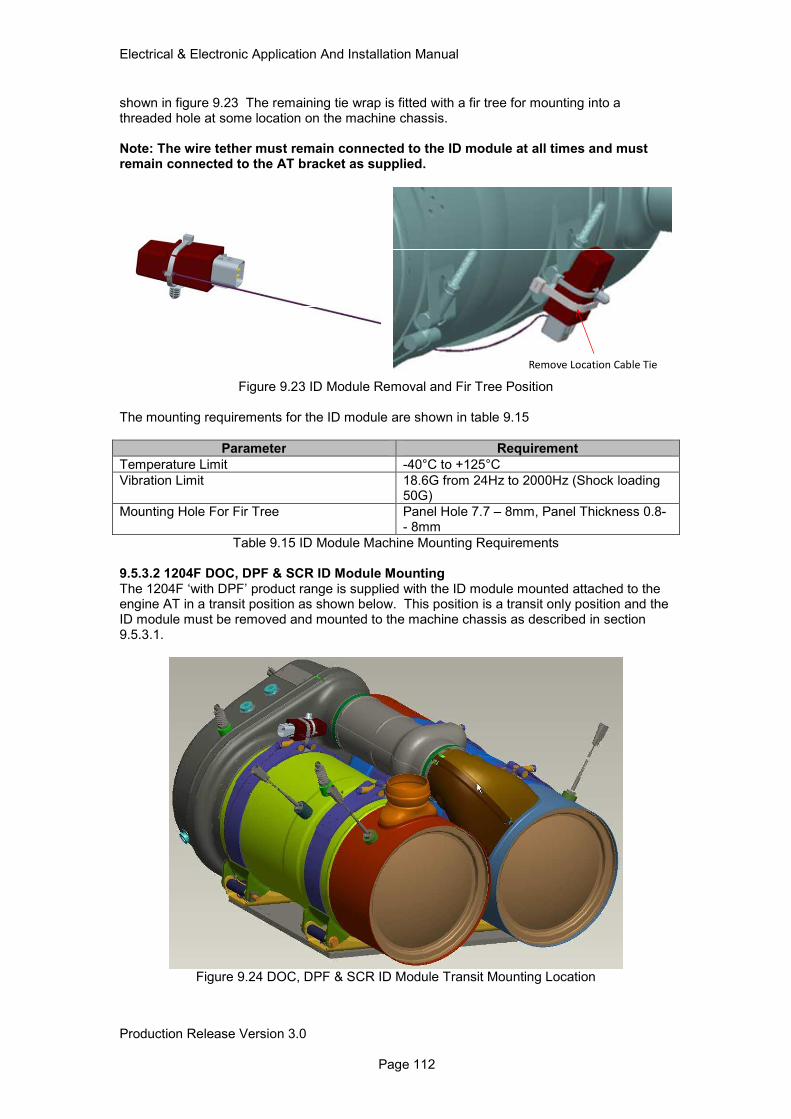
Electrical & Electronic Application And Installation Manual
Production Release Version 3.0 Page 112
shown in figure 9.23 The remaining tie wrap is fitted with a fir tree for mounting into a threaded hole at some location on the machine chassis. Note: The wire tether must remain connected to the ID module at all times and must remain connected to the AT bracket as supplied.
Remove Location Cable Tie
Figure 9.23 ID Module Removal and Fir Tree Position The mounting requirements for the ID module are shown in table 9.15
Parameter Requirement
Temperature Limit -40°C to +125°C
Vibration Limit 18.6G from 24Hz to 2000Hz (Shock loading 50G)
Mounting Hole For Fir Tree Panel Hole 7.7 – 8mm, Panel Thickness 0.8- - 8mm
Table 9.15 ID Module Machine Mounting Requirements 9.5.3.2 1204F DOC, DPF & SCR ID Module Mounting The 1204F ‘with DPF’ product range is supplied with the ID module mounted attached to the engine AT in a transit position as shown below. This position is a transit only position and the ID module must be removed and mounted to the machine chassis as described in section 9.5.3.1.
Figure 9.24 DOC, DPF & SCR ID Module Transit Mounting Location
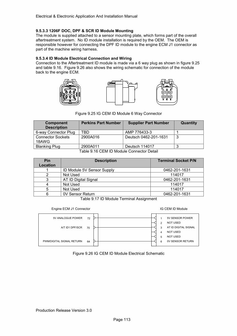
Electrical & Electronic Application And Installation Manual
Production Release Version 3.0 Page 113
9.5.3.3 1206F DOC, DPF & SCR ID Module Mounting The module is supplied attached to a sensor mounting plate, which forms part of the overall aftertreatment system. No ID module installation is required by the OEM. The OEM is responsible however for connecting the DPF ID module to the engine ECM J1 connector as part of the machine wiring harness. 9.5.3.4 ID Module Electrical Connection and Wiring Connection to the Aftertreatment ID module is made via a 6 way plug as shown in figure 9.25 and table 9.16. Figure 9.26 also shows the wiring schematic for connection of the module back to the engine ECM.
Figure 9.25 IG CEM ID Module 6 Way Connector
Component Description
Perkins Part Number Supplier Part Number Quantity
6-way Connector Plug TBD AMP 776433-3 1
Connector Sockets 18AWG
2900A016 Deutsch 0462-201-1631 3
Blanking Plug 2900A011 Deutsch 114017 3
Table 9.16 CEM ID Module Connector Detail
Pin Location
Description Terminal Socket P/N
1 ID Module 5V Sensor Supply 0462-201-1631
2 Not Used 114017
3 AT ID Digital Signal 0462-201-1631
4 Not Used 114017
5 Not Used 114017
6 0V Sensor Return 0462-201-1631
Table 9.17 ID Module Terminal Assignment
Figure 9.26 IG CEM ID Module Electrical Schematic
1 5V SENSOR POWER
2 NOT USED
3 AT ID DIGITAL SIGNAL
4 NOT USED
5 NOT USED
6 0V SENSOR RETURN
IG CEM ID Module
70A/T ID1 DPF/SCR
64PWM/DIGITAL SIGNAL RETURN
725V ANALOGUE POWER
Engine ECM J1 Connector
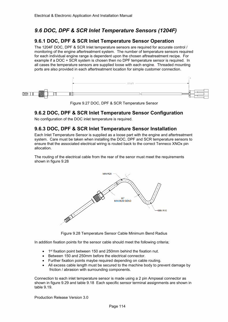
Electrical & Electronic Application And Installation Manual
Production Release Version 3.0 Page 114
9.6 DOC, DPF & SCR Inlet Temperature Sensors (1204F)
9.6.1 DOC, DPF & SCR Inlet Temperature Sensor Operation
The 1204F DOC, DPF & SCR Inlet temperature sensors are required for accurate control / monitoring of the engine aftertreatment system. The number of temperature sensors required for each individual engine range is dependent upon the chosen aftreatreatment recipe. For example if a DOC + SCR system is chosen then no DPF temperature sensor is required. In all cases the temperature sensors are supplied loose with each engine. Threaded mounting ports are also provided in each aftertreatment location for simple customer connection.
Figure 9.27 DOC, DPF & SCR Temperature Sensor
9.6.2 DOC, DPF & SCR Inlet Temperature Sensor Configuration
No configuration of the DOC inlet temperature is required.
9.6.3 DOC, DPF & SCR Inlet Temperature Sensor Installation Each Inlet Temperature Sensor is supplied as a loose part with the engine and aftertreatment system. Care must be taken when installing the DOC, DPF and SCR temperature sensors to ensure that the associated electrical wiring is routed back to the correct Tenneco XNOx pin allocation. The routing of the electrical cable from the rear of the senor must meet the requirements shown in figure 9.28
Figure 9.28 Temperature Sensor Cable Minimum Bend Radius
In addition fixation points for the sensor cable should meet the following criteria;
• 1st fixation point between 150 and 250mm behind the fixation nut.
• Between 150 and 250mm before the electrical connector.
• Further fixation points maybe required depending on cable routing.
• All excess cable length must be secured to the machine body to prevent damage by friction / abrasion with surrounding components.
Connection to each inlet temperature sensor is made using a 2 pin Ampseal connector as shown in figure 9.29 and table 9.18 Each specific sensor terminal assignments are shown in table 9.19.
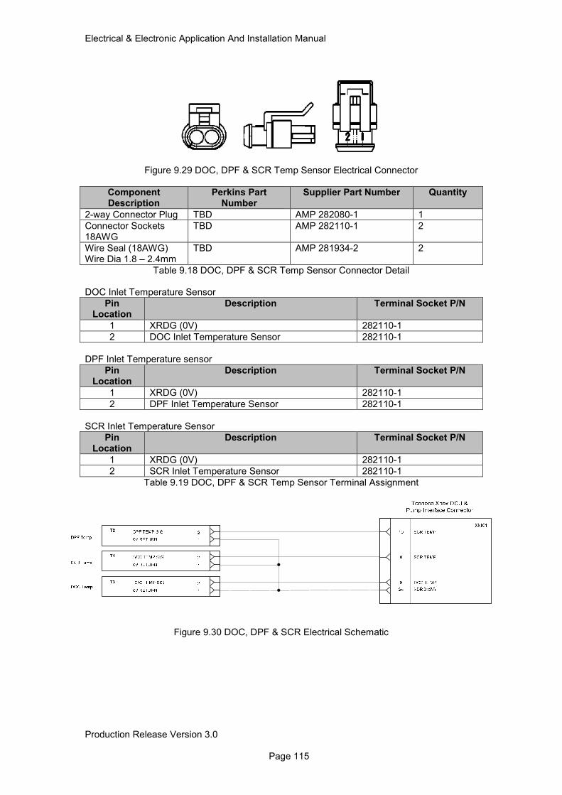
Electrical & Electronic Application And Installation Manual
Production Release Version 3.0 Page 115
Figure 9.29 DOC, DPF & SCR Temp Sensor Electrical Connector
Component Description
Perkins Part Number
Supplier Part Number Quantity
2-way Connector Plug TBD AMP 282080-1 1
Connector Sockets 18AWG
TBD AMP 282110-1 2
Wire Seal (18AWG) Wire Dia 1.8 – 2.4mm
TBD AMP 281934-2 2
Table 9.18 DOC, DPF & SCR Temp Sensor Connector Detail DOC Inlet Temperature Sensor
Pin Location
Description Terminal Socket P/N
1 XRDG (0V) 282110-1
2 DOC Inlet Temperature Sensor 282110-1
DPF Inlet Temperature sensor
Pin Location
Description Terminal Socket P/N
1 XRDG (0V) 282110-1
2 DPF Inlet Temperature Sensor 282110-1
SCR Inlet Temperature Sensor
Pin Location
Description Terminal Socket P/N
1 XRDG (0V) 282110-1
2 SCR Inlet Temperature Sensor 282110-1
Table 9.19 DOC, DPF & SCR Temp Sensor Terminal Assignment
Figure 9.30 DOC, DPF & SCR Electrical Schematic
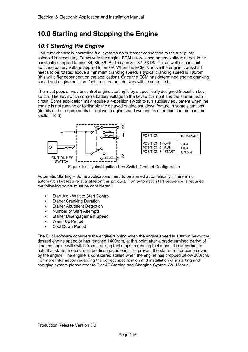
Electrical & Electronic Application And Installation Manual
Production Release Version 3.0 Page 116
10.0 Starting and Stopping the Engine
10.1 Starting the Engine Unlike mechanically controlled fuel systems no customer connection to the fuel pump solenoid is necessary. To activate the engine ECM un-switched battery voltage needs to be constantly supplied to pins 84, 85, 86 (Batt +) and 81, 82, 83 (Batt -), as well as constant switched battery voltage applied to pin 69. When the ECM is active the engine crankshaft needs to be rotated above a minimum cranking speed, a typical cranking speed is 180rpm (this will differ dependent on the application). Once the ECM has determined engine cranking speed and engine position, fuel pressure and delivery will be controlled. The most popular way to control engine starting is by a specifically designed 3 position key switch. The key switch controls battery voltage to the keyswitch input and the starter motor circuit. Some application may require a 4-position switch to run auxiliary equipment when the engine is not running or to disable the delayed engine shutdown feature in some situations (details of the requirements for delayed engine shutdown and its operation can be found in section 16.3).
OFF
ON
START
IGNITION KEY
SWITCH
START
4
3
1
2
POSITION
POSITION 1 - OFF
POSITION 2 - RUN
POSITION 3 - START
TERMINALS
2 & 4
1 & 4
1, 3 & 4
Figure 10.1 typical Ignition Key Switch Contact Configuration
Automatic Starting – Some applications need to be started automatically. There is no automatic start feature available on this product. If an automatic start sequence is required the following points must be considered:
• Start Aid - Wait to Start Control
• Starter Cranking Duration
• Starter Abutment Detection
• Number of Start Attempts
• Starter Disengagement Speed
• Warm Up Period
• Cool Down Period The ECM software considers the engine running when the engine speed is 100rpm below the desired engine speed or has reached 1400rpm, at this point after a predetermined period of time the engine will switch from cranking fuel maps to running fuel maps. It is important to note that starter motors must be disengaged earlier to prevent the starter motor being driven by the engine. The engine is considered stalled when the engine has dropped below 300rpm. For more information regarding the correct specification and installation of a starting and charging system please refer to Tier 4F Starting and Charging System A&I Manual.
Electrical & Electronic Application And Installation Manual
Production Release Version 3.0 Page 117
10.2 Stopping the Engine (and Preventing Restart) There is often some confusion about the different methods and devices used to either stop the engine or to prevent it from starting. These devices may be divided into the following categories:
• Ignition Keyswitch
• Battery Isolation Switch
• Remote Stop Button
• Datalink stop
• Engine Air Shutoff Each of these devices is described below to assist the OEM in selecting the method that is most suitable for machine and market. It remains, however, the responsibility of the OEM to ensure compliance of the machine with any specific legislation for the territories into which it is sold. It is recommended that the OEM perform a risk assessment such as a Failure Mode Effects Analysis (FMEA) on the application to determine the most appropriate method of stopping the engine and/or preventing it from being restarted. Note: Cutting all electrical power from the engine whilst it is running will result in an uncontrolled shutdown of the high pressure fuel system. Uncontrolled fuel system shutdowns are likely to compromise the reliability of the high pressure fuel pump. Therefore the methods detailed below are the only recommended ways of stopping the engine. It should be noted that under certain circumstances the engine ECM will remain active i.e. electrically active post ignition key power off. This is required for a number of engine calibration activities to take place. For this reason the main ECM supply power (un-switched battery) must not be removed during normal engine stopping. Removing the ECM un-switched battery supply will cause these calibrations to be interrupted and the values measured on the previous key cycle will be used. If the engine ECM is operated for long periods without performing these calibrations, engine performance may be affected and a diagnostic will be raised. During this period the engine ECM will also require a certain level of current from the system batteries for a short period of time. For this reason care must be taken when working on the engine post ignition key off.
10.2.1 Ignition Keyswitch
It is a Perkins requirement that all machines have a simple intuitive and accessible method of stopping the engine. This will normally be a directly wired Ignition Keyswitch. When the keyswitch is turned to the off position or when the key is removed, power must be removed from the ignition keyswitch pin (pin 69) of the ECM J1 connector. Switching devices may also be placed in series with the ignition keyswitch input to provide a remote stop feature. It is recommended that the switch is a latched contact type as closing the switch whilst the engine is shutting down could cause the engine to restart. In the event of Delayed Engine shutdown being activated as a protection feature on the 1206F product range a 4 position key switch is recommended. A 4 position key switch will be used to provide the following functionality;
• Ignition OFF
• Ignition ON
• Crank
• Delayed Engine Shutdown Override. The delayed engine shutdown override position of the key switch must be wired via a relay back to the User Defined Shutdown J1 input. More information on the installation of the keyswitch and interaction with DES can be found in section 16.3.

Electrical & Electronic Application And Installation Manual
Production Release Version 3.0 Page 118
10.2.2 Battery Isolation Switches
Battery Isolation switches are usually fitted in the battery or the engine compartment of a machine. On some machines there may be a small number of low current devices which are not switched off by this device e.g. clocks or anti-theft tracking devices. The function of a battery isolation switch is as follows:
• Prevent battery discharge during vehicle shipping or storage
• Protect service technicians from danger caused by inadvertent engine crank or start .To offer good protection of service personnel is it possible to provide a switch which can be locked in the open position (e.g. with a padlock) and the key removed and given to the service engineer who is working on the dangerous components
The battery isolation switch is not a suitable method for stopping an engine, as it is not guaranteed to stop the engine as the ECM may continue to operate with power generated by the alternator. It is also possible that opening the battery isolation switch when the engine is running will cause an “alternator load dump”. This is a kind of electrical transient that can cause damage to electronic components Battery isolation switches are normally fitted in the negative path, close to the battery.
10.2.3 User Defined Shutdown Switch (Remote Shutdown)
10.2.3.1 User defined Shutdown Switch Operation Remote stop is intended to provide a convenient method of stopping the engine. It is not designed to be fail safe and so should not be used to assure the protection of either personnel or equipment Remote stop buttons may be used on large machines, which can be operated from ground level and where the operator wants to stop the machine without climbing into the cab. There are a number of variations on remote stop button circuits. The engine uses a single normally open contact, which must be closed to stop the engine. The remote stop button will function as follows: When the switched is closed (or if a button is stopped for longer than 150msec), then the engine will stop. The ECM will remain ON, so it will continue to communicate over J1939 and with the service tool. Note however that it will continue to draw power from the battery so if it is left in this state it will eventually result in a flat battery. The engine may be restarted by opening the switch and activating the starter motor. The red “mushroom” emergency stop buttons must not be used for remote stop functions as they may be mistaken for emergency stop buttons as described above. The User defined shutdown feature is also available via J1939 using the PGN F001 /SPN 970 detailed in section 10.2.3.3 10.2.3.2 User Defined Shutdown Switch Configuration The user defined shutdown feature must be enabled within the engine ECM using the service tool. 10.2.3.3 User Defined Shutdown Switch Installation A single switch to ground input on pin 68 of the ECM J1 Connector (Several stop buttons can therefore be connected in parallel).
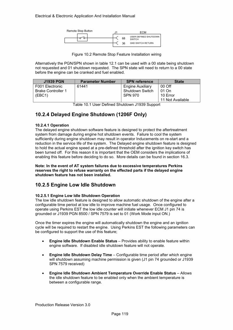
Electrical & Electronic Application And Installation Manual
Production Release Version 3.0 Page 119
36 GND SWITCH RETURN
68USER DEFINED SHUTDOWN
SWITCH
ECMJ1Remote Stop Button
Figure 10.2 Remote Stop Feature Installation wiring
Alternatively the PGN/SPN shown in table 12.1 can be used with a 00 state being shutdown not requested and 01 shutdown requested. The SPN state will need to return to a 00 state before the engine can be cranked and fuel enabled.
J1939 PGN Parameter Number SPN reference State
F001 Electronic Brake Controller 1 (EBC1)
61441 Engine Auxiliary Shutdown Switch SPN 970
00 Off 01 On 10 Error 11 Not Available
Table 10.1 User Defined Shutdown J1939 Support
10.2.4 Delayed Engine Shutdown (1206F Only)
10.2.4.1 Operation The delayed engine shutdown software feature is designed to protect the aftertreatment system from damage during engine hot shutdown events. Failure to cool the system sufficiently during engine shutdown may result in operator Inducements on re-start and a reduction in the service life of the system. The Delayed engine shutdown feature is designed to hold the actual engine speed at a pre-defined threshold after the ignition key switch has been turned off. For this reason it is important that the OEM considers the implications of enabling this feature before deciding to do so. More details can be found in section 16.3. Note: In the event of AT system failures due to excessive temperatures Perkins reserves the right to refuse warranty on the effected parts if the delayed engine shutdown feature has not been installed.
10.2.5 Engine Low Idle Shutdown
10.2.5.1 Engine Low Idle Shutdown Operation The low idle shutdown feature is designed to allow automatic shutdown of the engine after a configurable time period at low idle to improve machine fuel usage. Once configured to operate using Perkins EST the low idle counter will initiate whenever ECM J1 pin 74 is grounded or J1939 PGN 8500 / SPN 7579 is set to 01 (Work Mode input ON.) Once the timer expires the engine will automatically shutdown the engine and an ignition cycle will be required to restart the engine. Using Perkins EST the following parameters can be configured to support the use of this feature;
• Engine Idle Shutdown Enable Status – Provides ability to enable feature within engine software. If disabled idle shutdown feature will not operate.
• Engine Idle Shutdown Delay Time – Configurable time period after which engine will shutdown assuming machine permission is given (J1 pin 74 grounded or J1939 SPN 7579 received)
• Engine Idle Shutdown Ambient Temperature Override Enable Status – Allows the idle shutdown feature to be enabled only when the ambient temperature is between a configurable range.
Electrical & Electronic Application And Installation Manual
Production Release Version 3.0 Page 120
• Engine Idle Shutdown Minimum Ambient Air Temperature – Lower ambient temperature limit below which the idle shutdown feature is disabled. Used to ensure shutdown in not activated in conditions where engine starting may be difficult.
• Engine Idle Shutdown Maximum Ambient Air Temperature – Higher ambient temperature above which the engine shutdown feature will not be activated. Idle shutdown will operate between the min and max ambient temperature settings.
Initiation of the low idle shutdown timer is also reliant on the following engine conditions being met;
• Work Mode input ON
• Engine speed at Low Idle +/- 50rpm
• Coolant temp above 70°C
• Load factor is less than 100%
• Battery voltage at ECM input is above 12.5V (12V system) and 24.5V (24V system).
• DPF Inlet temp (DPF product only) less than 400DegC.
• Ambient air temp inside configurable threshold (EST configurable parameter)
Note: Pin 74 and PGN 8500 / SPN 7579 are also used as inputs for the elevated idle strategy detailed in section 17 of this document. In the event that an elevated idle request is needed this function will take priority over the idle shutdown. This functionality needs to be considered when implementing this feature. 10.2.5.2 Engine Low Idle shutdown Configuration The following configurable parameters are provided and can be adjusted using Perkins EST.
EST Parameter Description Min Value Max Value Default
Engine Shutdown Enable Status
Enables shutdown feature Disabled Enabled Disabled
Engine Idle Shutdown Delay Time
Time after which engine will shutdown
1 minute 1440 minutes
5 minutes
Engine Idle Shutdown Ambient Temperature Override enable Status
Enables the use of ambient temperature as a boundary condition for use of engine shutdown
Disabled Enabled Disabled
Engine Idle Shutdown Minimum Ambient Air Temperature
Ambient temperature below which the Idle shutdown will be inhibited
-40°C 99°C 0°C
Engine Idle Shutdown Maximum Ambient Air Temperature
Ambient temperature above which idle shutdown will be inhibited
-39°C 100°C 30°C
Table 10.2 Low Idle Shutdown Configurable Parameters
10.2.5.3 Engine Low Idle Shutdown Installation Once Perkins EST has been configured to activate the use of the Idle Shutdown feature the only installation work required is to determine the method by which the machine will indicate it is safe for the idle shutdown timer to begin. There are two methods available and these are shown in figure 10.3 and table 10.3. Note: Only one of the methods shown below should be used on machine as once activated the J1939 method will override the signals provided by ECM J1 pin 74.
Electrical & Electronic Application And Installation Manual
Production Release Version 3.0 Page 121
Note: Please refer to section 17 before installing this feature and associated wiring / CAN communication. The same ECM inputs are used to communicate acceptance of elevated idle requests by the engine ECM and so a machine FMEA needs to be completed before selecting when to activate these inputs.
Figure 10.3 Hardwired Machine Safe State Input
J1939 PGN Parameter Number SPN reference State
8500 CAB Message 2 (CM2)
34048 Elevated Engine Speed Allowed Switch SPN 7579*
00 Not Allowed 01 Allowed 10 Error 11 Not Available
Table 10.3 J1939 Machine Safe State Input
* Description aligns with J1939 protocol. Status is used to communicate ‘Machine Safe State’ condition and so applies to elevated idle and idle shutdown features.
Electrical & Electronic Application And Installation Manual
Production Release Version 3.0 Page 122
10.2.6 Intake Air Shutoff Valve
10.2.6.1 Intake Air Shutoff Valve Operation There are industries where flammable gases could be inhaled by the engine, potentially resulting in engine speed runaway. The engine software shall monitor engine speed. If a predefined engine speed is exceeded the engine software shall invoke the shutoff process, this involves disabling fuelling and closing an intake shutoff valve (valve installed by the customer). This feature will aid stopping the engine in a runaway condition. Some regulatory requirements, in Mining and Petrochemical industries for example, stipulate the use of an engine intake shutoff. This feature allows the user to control an air shutoff system, by monitoring engine speed and activating the air shutoff valve output driver when required. Once installed using the service tool the engine software monitors the measured engine speed and compares it to a maximum engine speed limit, which must also be configured using the service tool. When the engine exceeds the configured engine overspeed shutdown value, the fuel injection is disabled and the air shutoff valve activated. Once the shutoff valve is activated the key switch must be cycled to de-activate the solenoid control. 10.2.6.2 Intake Air Shutoff Valve Configuration One parameter must be configured using the service tool prior to using the intake air shutoff solenoid. Within the ‘configuration screen’, air shutoff defaults to “disabled” and must be set to “enabled”. Once installed the engine monitoring system parameter for engine overspeed may be changed to establish the level of protection necessary for the specific installation. Please refer to section 14 for more information regarding the configuration of the engine overspeed limit. 10.2.6.3 Intake Air Shutoff Valve Installation The intake air shutoff valve is controlled by the engine ECM using an electrical solenoid. The solenoid requires electrical connection to the engine ECM as shown in figure 10.4.
Figure 10.4 Intake Air Shutoff Valve Installation Wiring
49 2A ACTUATOR DRIVER RETURN
53 AIR SHUTOFF SOLENOID
Electrical & Electronic Application And Installation Manual
Production Release Version 3.0 Page 123
10.2.7 Overspeed Verify Switch
The overspeed verify switch compliments the Air Intake Shutoff feature. The overspeed verify switch allows the user to verify that the shutoff feature is operating correctly without exceeding or reaching the engine overspeed speed limit. The switch input allows the user to test the air intake shutoff feature at 75 percent of the engine speed limit. The switch is a normally open switch. When the switch is closed and the actual engine speed is equal to or exceeds 75 percent of the pre-programmed engine limit the air intake shutoff feature is activated. Figure 10.5 shows the Wiring required for this feature to be activated.
Figure 10.5 Overspeed Verify Switch Installation Wiring
10.2.8 Datalink stops As with the remote stop button, described above, the datalink stop is not fail safe and does not meet the requirements of emergency stop legislation so should not be relied on to assure the safety of machine operators or other personnel. Datalink stops may be used in the following circumstances;
• Immobilisers
• Machine protection strategies
• Automatic machine features (e.g. idle shutdown timer)
• Stopping machines by radio control or other telemetry. Geo-fencing is a particular application, where a machine will not operate outside defined map coordinates
It is recommended that if such features are implemented, then they are clearly documented and communicated to the final users and owners of the machine. If this is not done then there may be complaints that the engine is stopping unexpectedly.
10.2.9 Engine Emergency Stops
It is the customer responsibility to complete a risk assessment on their product when considering the use and function of an emergency stop device. If residual risks remain on the product that the customer wants to mitigate by use of an emergency stop function, the following methods of emergency stopping the engine may be considered. The most appropriate method of emergency stop will depend on the application and appropriate regulations. Using a combination of the methods below may provide a more robust emergency stop solution. Using an emergency stop in situations other than an emergency could result in engine damage. In the event of fuel shut off solenoid failure, cutting electrical power on mechanical engines may not stop the engine. In the event of an injector failure, cutting electrical power on electronic common rail engines may not stop the engine. For detailed information on how to implement the following methods of E-Stop consult your applications lead.
• Cut electrical power to engine - un-switched positive Power should be isolated between the battery positive terminal and the battery positive pins on the engine ECM.
• Cut electrical power to engine - un-switched positive and negative Cutting positive power - Power should be isolated between the battery positive terminal and the battery positive pins on the engine ECM. Cutting negative return - A double pole/double throw switch should be placed in a position on machine that will ensure main negative power and main positive power are disconnected upon switch activation.
36 SWITCH INPUT RETURN
50FAN REVERSE SWITCH /
OVERSPEED VERIFY SWITCH
OVERSPEED VERIFY SWITCH

Electrical & Electronic Application And Installation Manual
Production Release Version 3.0 Page 124
• Cut air supply to engine – Slicer valve placed after the turbocharger compressor.
10.2.10 Common problems with the application of stop devices
It is possible, although extremely rare, that diesel engines continue to run even if all electrical power is removed. This can happen when high quantities of oil vapour or other inflammable gases are present in the air into the engine. The only way to prevent this is to provide an air inlet shut-off valve (slicer valve). It is not common practice to fit such devices to all engines, but they should be considered where there is a risk of flammable gases (e.g. in petroleum applications), or where the application demands high engine grade ability (slopes). Some hazards are present when the engine is being cranked by the starter motor, as well as when it is running. For example, components will still rotate, hydraulic pressure will still be present, and fuel may still be pump to high pressures.
Electrical & Electronic Application And Installation Manual
Production Release Version 3.0 Page 125
11.0 Engine Cooling Fan Control
11.1 Hydraulic Fan Control Both 1204 and 1206F products are supplied with engine software capable of supporting the control of a Hydraulic cooling fan valve. This feature enables a hydraulically controlled fan arrangement to be controlled directly from the engine ECM, removing the need for additional controllers. The engine ECM provides a configurable current output to a hydraulic valve to vary the speed of the hydraulic fan. The solenoid required to control the oil flow to the fan is not provided by Perkins and must be sourced by the customer.
11.1.1 Hydraulic Fan Control Operation
The fan control feature is suitable for the control of hydraulic fans only. The control of the fan speed is made using a number of configurable sensor inputs including;
• Engine Coolant Temperature (Mandatory)
• Engine Charge Air Cooler Outlet Temperature (Mandatory)
• Auxiliary Temperature
• J1939 Inputs for Transmission Oil and Hydraulic Oil Temperatures. The default minimum requirement for the fan strategy to operate correctly is with the coolant temperature and charge air cooler outlet temperature (shown as mandatory above). While the coolant temperature sensor is installed on engine as standard, the charge air cooler temperature is an additional sensor which needs to be installed by the customer when the fan strategy option is selected. A port is provided on all engines for the installation of the charge air sensor. The fan strategy operates in an open loop mode meaning that no fan speed feedback is provided to the engine ECM. Fan speed control is provided by a managed current output from the engine ECM only. Before attempting to use this feature it is important that the system parameters described in table 11.1 are understood.
11.1.2 Hydraulic Fan Control Configuration Configuration of the Hydraulic fan speed control feature can be achieved using Perkins EST. Table 11.1 shows the configurable fields available within Perkins EST and their minimum / maximum values. The fan feature is designed to operate between a minimum and maximum fan current (determined by the hydraulic valve manufacturer) which results in a set fan speed range. Temperature configurations for the engine coolant temp and ATAAC temp are then used to control the ECM output current and the resulting fan speed during operation. Fan speed is not used as a control parameter for the hydraulic fan feature and so must be determined by the OEM during testing and resulting current inserted into Perkins EST.
Electrical & Electronic Application And Installation Manual
Production Release Version 3.0 Page 126
Parameter Min Valve Max Value Operation
Engine Fan Control OFF ON Enables / disables the fan feature.
Engine Fan Type Configuration*
Direct Drive Viscous Clutch
Configures the fan control type required. Only Variable Hydraulic fan is supported.
Engine Cooling Fan Temperature Error Increasing Hysteresis
0% 100% Ensures smooth ramping of fan speed as error increases.
Engine Cooling Fan Temperature Error Decreasing Hysteresis
0% 100% Ensures smooth ramping of fan speed as error decreases.
Engine Cooling Fan Current Ramp Rate
0A/sec 3.0A/sec Rate at which the fan speed will increase per second for a given change in current demand.
Top Engine Fan Speed 0 2800rpm Max fan speed (not used).
Minimum Desired Engine Colling Fan Speed
0 2800rpm Min fan speed (not used).
Engine Cooling Fan Solenoid Minimum Current
0.010A 3.7A Min current = max fan speed (inverse proportional fan).
Engine Cooling Fan Solenoid Maximum Current
0.010A 3.7A Max current = min fan speed (Inverse proportional fan).
Engine Cooling Fan Solenoid Dither Frequency
30Hz 500Hz Rated dither frequency of valve.
Engine cooling Fan Solenoid Dither Amplitude (Peak-to-Peak)
0A 1A Rated dither amplitude of valve.
Table 11.1 Hydraulic Fan control Configuration EST Parameters The engine temperature points at which the fan speed is a min and max value are configurable using the service tool. Fan control is achieved using two engine temperatures as standard. Table 11.2 describes the default fan min and max air flow settings.
Parameter Min Value Max Value Default
Engine Cooling Fan Max Air Flow Charge Air Cooler Outlet Temperature
0°C 120°C 45°C
Engine Cooling Fan Min Air Flow Charge Air Cooler Outlet Temperature
0°C 120°C 40°C
Engine Cooling Fan Max Air Flow Coolant Temperature
0°C 120°C 102°C
Engine Cooling Fan Min Air Flow Coolant Temperature
0°C 120°C 92°C
Table 11.2 Mandatory Fan Control Temperature Parameters Configuration requirements for the chosen hydraulic valve can be found within the component technical data sheet or by contacting the valve supplier directly. Perkins does not offer a hydraulic fan valve option for engine fan control. Note: For the Charge Air cooler Outlet Temperature Sensor to operate correctly. The sensor option must also be installed using Perkins EST. The configuration parameter used to activate the sensor is shown below.
Electrical & Electronic Application And Installation Manual
Production Release Version 3.0 Page 127
11.1.3 Hydraulic Fan control Installation
The engine ECM has dedicated output drivers for controlling the hydraulic fan solenoid as well as the Charge Air Cooler Outlet Temperature Sensor input signal. Installation wiring for these items is shown in figure 11.1.
Figure 11.1 Hydraulic Fan Installation Wiring
The charge Air Cooler Temperature sensor must be supplied by Perkins and can be sourced direct from factory as a bulk supply item. The parts required and mating connector are shown in table 11.3.
Component Description
Perkins Part Number
Supplier Part Number Quantity
Temperature Sensor (Metric)
2566454 N/A 1
Sealing O-ring 2287103 N/A 1
2 Way Amp Seal 28170044 AMP 776427-1 1
Sockets 18AWG 2900A009 Deutsch 0462-201-16141 2
Table 11.3 Charge Air Temperature Sensor Parts Sensor mounting position and port is shown in figure 11.2
Electrical & Electronic Application And Installation Manual
Production Release Version 3.0 Page 128
Port For Charge
Air Sensor
Figure 11.2 Charge Air Temperature Sensor Installation Port
When Installing and testing the hydraulic fan it is important that the system is fully validated in line with the normal cooling pack performance sign off criteria. Failure to correctly install and configure the cooling fan features can result in a range of engine cooling problems. Extensive field tests at various ambient temperatures are advised to ensure that the fan performs as expected. Perkins does not accept any responsibility for engine issues caused by the incorrect application of the Hydraulic fan control feature.
Electrical & Electronic Application And Installation Manual
Production Release Version 3.0 Page 129
12.0 Engine Speed Demand It is necessary to select a device that converts the speed requirements of the engine operator or controller to an electrical signal recognized by the engine ECM. There are five types of speed demand input:
• Pulse Width Modulation (PWM) Sensor
• Analogue Sensor
• Throttle lock (PTO mode) - also known as “engine speed cruise control” or “set speed control”.
• Multi Position Throttle Switches (MPTS)
• Torque Speed Control - TSC1 (Speed control over CAN J1939) The speed demand type must be carefully considered and appropriate for the application. There are two dedicated software input channels that can be configured to accept specific types of speed demand inputs. The valid combinations and throttle logic are given in the following diagram. PTO mode can be used with Analogue/PWM combinations; it cannot be used with multi position switch. The J1939 TSC1 parameter will override any speed demand input when broadcast. Droop is applied to the requested desired engine speed only when All Speed governing is selected.
Figure 12.1 Engine Speed Demand Software Control
PWM Engine Throttle
ANALOGUE Engine
Throttle with IVS
MPTS (Multi Position
Throttle Switch)
Throttle Type Selection and Number of Throttles
(One throttle type selected for each channel)
Demand
ValidationDroop
Throttle 1&2
Arbitration
Overall
Arbitration with
other speed
demands
Mode Selection (including
Droop Value, High Idle,
Rated Speed and Gov
Selection)
Throttle Lock
(PTO mode)
Ramp Rates
TSC 1
PWM Engine Throttle
ANALOGUE Engine
Throttle with IVS
MPTS (Multi Position
Throttle Switch)
Demand
ValidationDroop
Throttle
Channel
2
Throttle
Channel
1
Desired Engine Speed
Electrical & Electronic Application And Installation Manual
Production Release Version 3.0 Page 130
12.1 Analogue Sensor
12.1.1 Analogue Sensor Operation
Two inputs are available for Analogue throttle devices, which may be pedal, lever or cable operated. The Analogue sensor gives a DC Analog output in the range 0.5 to 4.5 volts, when connected to the engine ECM. The ECM provides a regulated 5V 200mA power supply. The Analog sensor should use non-contact Hall effect technology. Robust potentiometer contact sensors designed for use in vehicles may be considered under no circumstances should ordinary carbon track or wire wound potentiometers be used, as they will not be reliable. For all mobile applications, and those where a rapid change in engine speed could cause a hazard, an idle validation switch is required. The idle validation switch closes to ground when the sensor is in the minimum position. Off idle switches and kickdown switches are not monitored by the engine ECM. This Analogue input must only be used to control engine speed from a direct operator input, and is not suitable as the mechanism for speed control by another electronic controller. There is no special requirement for a relationship between angular movement of the pedal and output voltage. This document does not measure component acceptability in terms of:
• Temperature
• Vibration
• Electromagnetic Compatibility
• Design life
• Supply voltage requirements (min, max, stability)
• Legal Compliance It the responsibility of the OEM and the throttle device manufacturer to ensure that the component is suitable for the application in which it is to be used.
12.1.2 Analogue Sensor Configuration
Before an analogue throttle can be used the configurable parameters must be programmed into the ECM via the service tool. These parameters are selectable in the main throttle configuration screen.
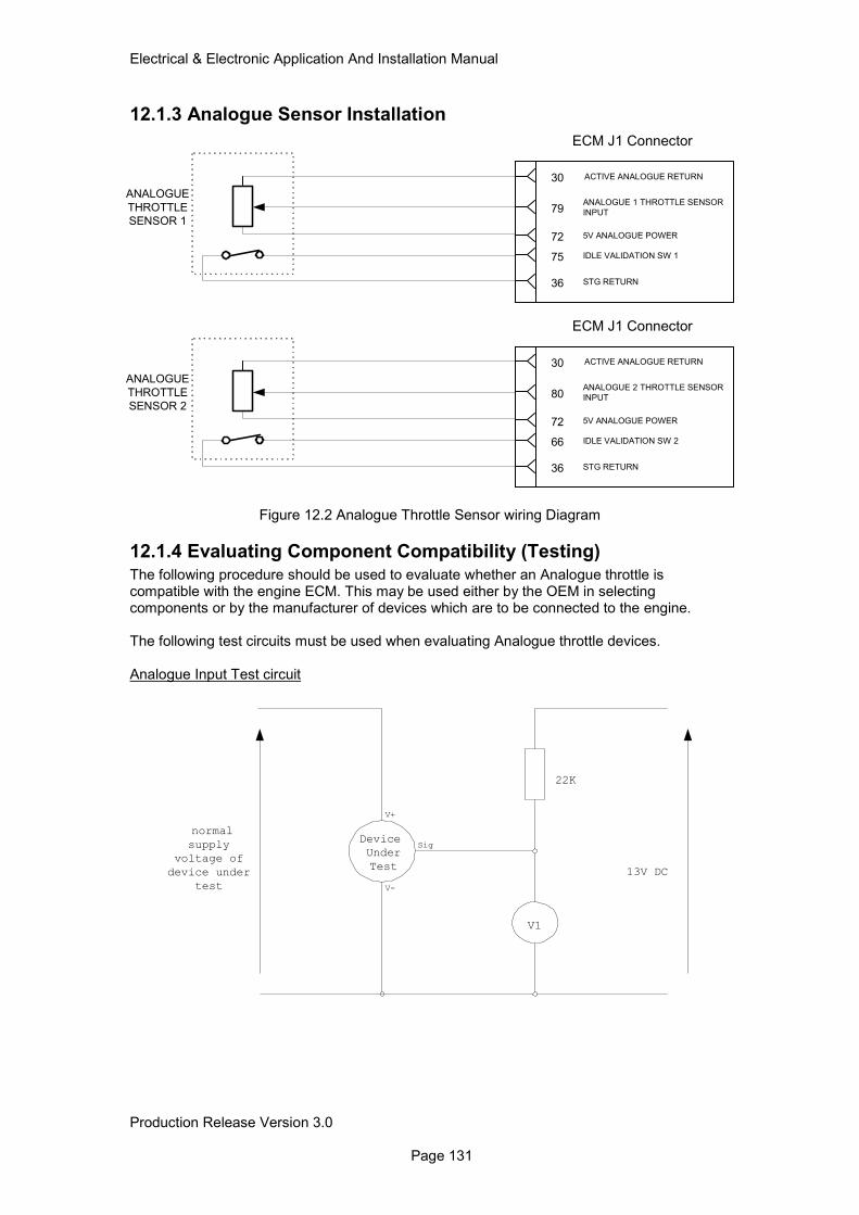
Electrical & Electronic Application And Installation Manual
Production Release Version 3.0 Page 131
12.1.3 Analogue Sensor Installation
Figure 12.2 Analogue Throttle Sensor wiring Diagram
12.1.4 Evaluating Component Compatibility (Testing)
The following procedure should be used to evaluate whether an Analogue throttle is compatible with the engine ECM. This may be used either by the OEM in selecting components or by the manufacturer of devices which are to be connected to the engine. The following test circuits must be used when evaluating Analogue throttle devices. Analogue Input Test circuit
22K
normal
supply
voltage of
device under
test
13V DC
V1
Device
Under
Test
Sig
V+
V-
72 5V ANALOGUE POWER
75 IDLE VALIDATION SW 1
30 ACTIVE ANALOGUE RETURN
ECM J1 Connector
36 STG RETURN
ANALOGUE
THROTTLE
SENSOR 179
ANALOGUE 1 THROTTLE SENSOR
INPUT
72 5V ANALOGUE POWER
66 IDLE VALIDATION SW 2
30 ACTIVE ANALOGUE RETURN
ECM J1 Connector
36 STG RETURN
ANALOGUE
THROTTLE
SENSOR 280
ANALOGUE 2 THROTTLE SENSOR
INPUT
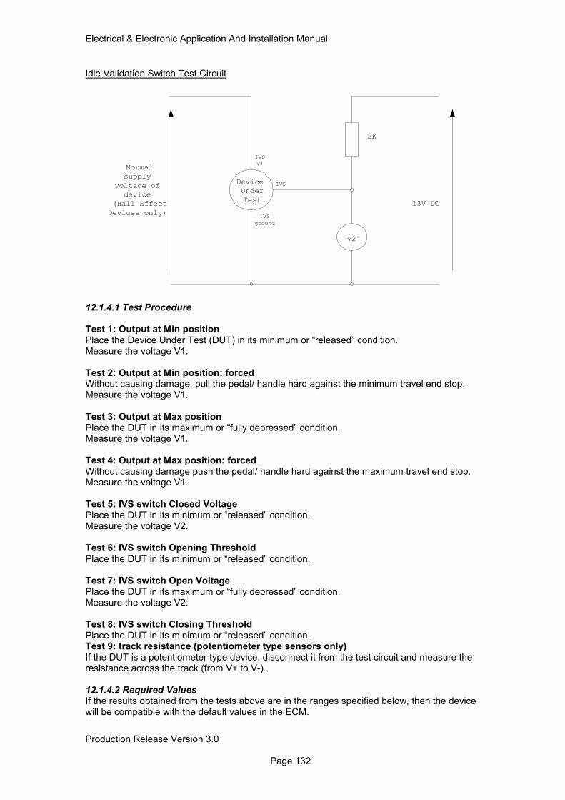
Electrical & Electronic Application And Installation Manual
Production Release Version 3.0 Page 132
Idle Validation Switch Test Circuit
2K
Normal
supply
voltage of
device
(Hall Effect
Devices only)
13V DC
V2
Device
Under
Test
IVS
IVS
V+
IVS
ground
12.1.4.1 Test Procedure Test 1: Output at Min position Place the Device Under Test (DUT) in its minimum or “released” condition. Measure the voltage V1. Test 2: Output at Min position: forced Without causing damage, pull the pedal/ handle hard against the minimum travel end stop. Measure the voltage V1. Test 3: Output at Max position Place the DUT in its maximum or “fully depressed” condition. Measure the voltage V1. Test 4: Output at Max position: forced Without causing damage push the pedal/ handle hard against the maximum travel end stop. Measure the voltage V1. Test 5: IVS switch Closed Voltage Place the DUT in its minimum or “released” condition. Measure the voltage V2. Test 6: IVS switch Opening Threshold Place the DUT in its minimum or “released” condition. Test 7: IVS switch Open Voltage Place the DUT in its maximum or “fully depressed” condition. Measure the voltage V2. Test 8: IVS switch Closing Threshold Place the DUT in its minimum or “released” condition. Test 9: track resistance (potentiometer type sensors only) If the DUT is a potentiometer type device, disconnect it from the test circuit and measure the resistance across the track (from V+ to V-). 12.1.4.2 Required Values If the results obtained from the tests above are in the ranges specified below, then the device will be compatible with the default values in the ECM.
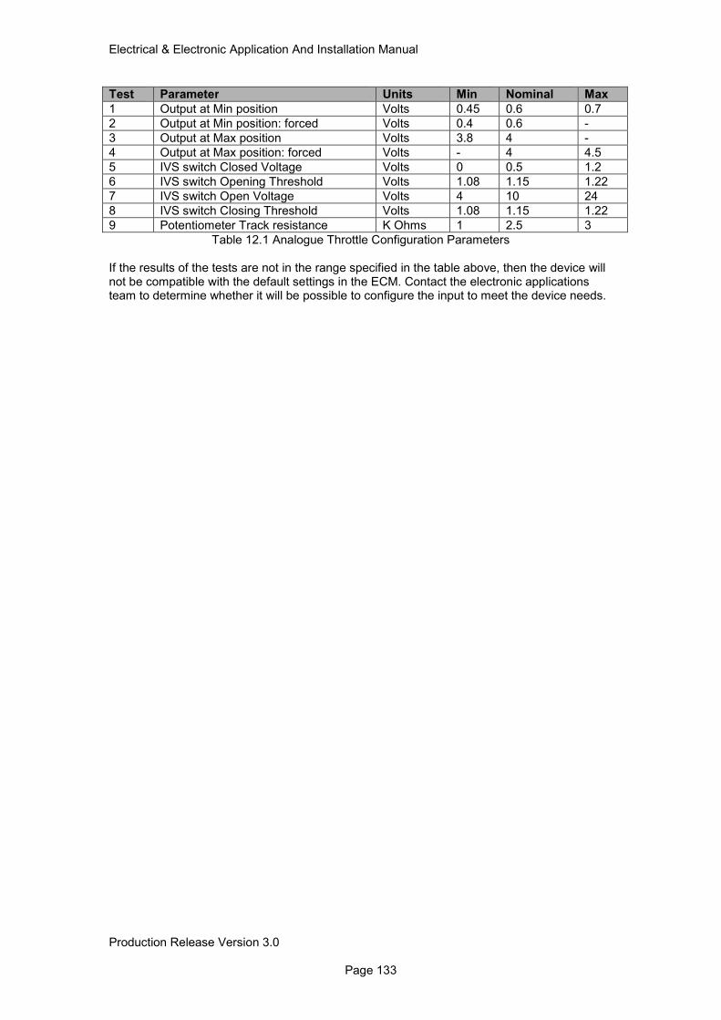
Electrical & Electronic Application And Installation Manual
Production Release Version 3.0 Page 133
Test Parameter Units Min Nominal Max
1 Output at Min position Volts 0.45 0.6 0.7
2 Output at Min position: forced Volts 0.4 0.6 -
3 Output at Max position Volts 3.8 4 -
4 Output at Max position: forced Volts - 4 4.5
5 IVS switch Closed Voltage Volts 0 0.5 1.2
6 IVS switch Opening Threshold Volts 1.08 1.15 1.22
7 IVS switch Open Voltage Volts 4 10 24
8 IVS switch Closing Threshold Volts 1.08 1.15 1.22
9 Potentiometer Track resistance K Ohms 1 2.5 3
Table 12.1 Analogue Throttle Configuration Parameters If the results of the tests are not in the range specified in the table above, then the device will not be compatible with the default settings in the ECM. Contact the electronic applications team to determine whether it will be possible to configure the input to meet the device needs.
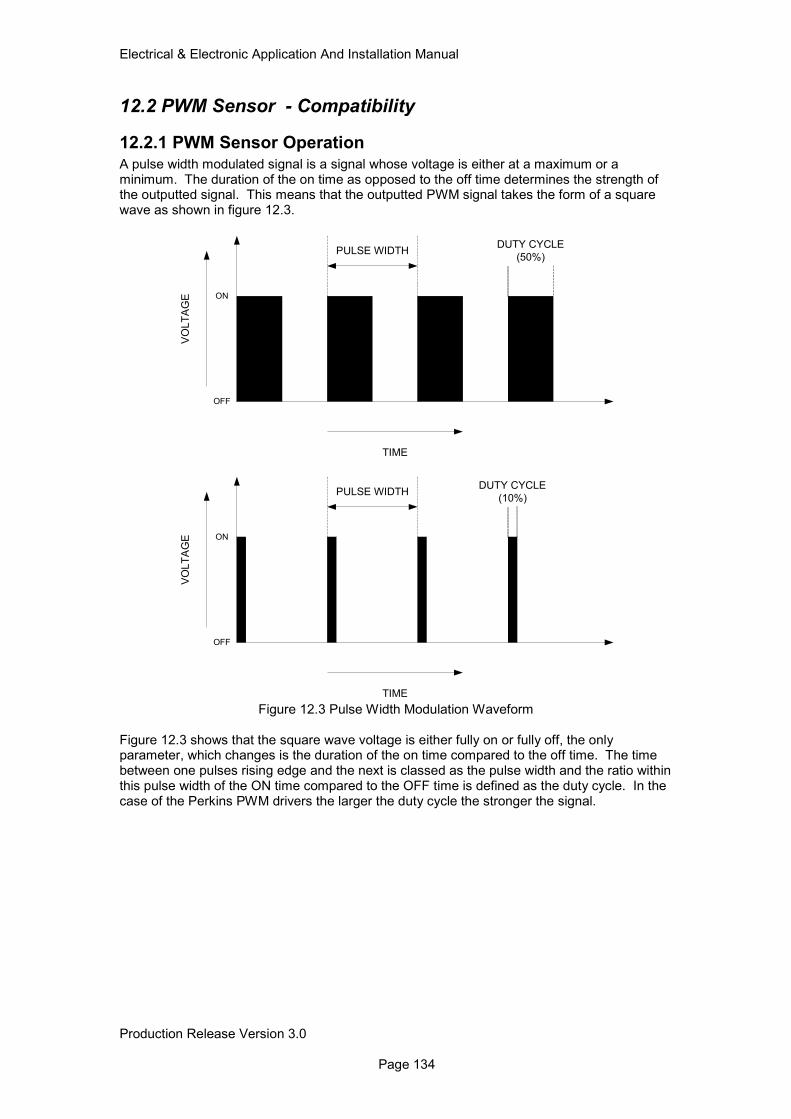
Electrical & Electronic Application And Installation Manual
Production Release Version 3.0 Page 134
12.2 PWM Sensor - Compatibility
12.2.1 PWM Sensor Operation
A pulse width modulated signal is a signal whose voltage is either at a maximum or a minimum. The duration of the on time as opposed to the off time determines the strength of the outputted signal. This means that the outputted PWM signal takes the form of a square wave as shown in figure 12.3.
Figure 12.3 Pulse Width Modulation Waveform Figure 12.3 shows that the square wave voltage is either fully on or fully off, the only parameter, which changes is the duration of the on time compared to the off time. The time between one pulses rising edge and the next is classed as the pulse width and the ratio within this pulse width of the ON time compared to the OFF time is defined as the duty cycle. In the case of the Perkins PWM drivers the larger the duty cycle the stronger the signal.
TIME
VO
LT
AG
E ON
OFF
PULSE WIDTHDUTY CYCLE
(50%)
TIME
VO
LT
AG
E ON
OFF
PULSE WIDTHDUTY CYCLE
(10%)
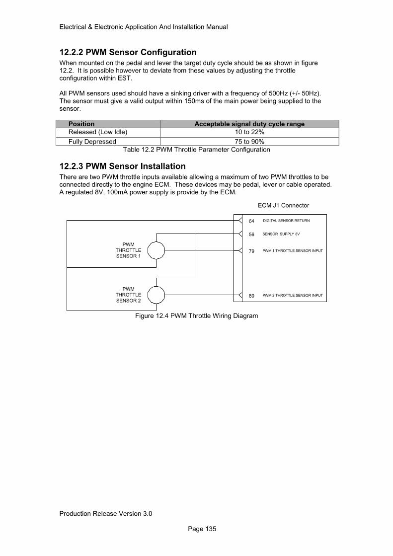
Electrical & Electronic Application And Installation Manual
Production Release Version 3.0 Page 135
12.2.2 PWM Sensor Configuration
When mounted on the pedal and lever the target duty cycle should be as shown in figure 12.2. It is possible however to deviate from these values by adjusting the throttle configuration within EST. All PWM sensors used should have a sinking driver with a frequency of 500Hz (+/- 50Hz). The sensor must give a valid output within 150ms of the main power being supplied to the sensor.
Position Acceptable signal duty cycle range
Released (Low Idle) 10 to 22%
Fully Depressed 75 to 90%
Table 12.2 PWM Throttle Parameter Configuration
12.2.3 PWM Sensor Installation
There are two PWM throttle inputs available allowing a maximum of two PWM throttles to be connected directly to the engine ECM. These devices may be pedal, lever or cable operated. A regulated 8V, 100mA power supply is provide by the ECM.
Figure 12.4 PWM Throttle Wiring Diagram
56 SENSOR SUPPLY 8V
PWM
THROTTLE
SENSOR 2
80 PWM 2 THROTTLE SENSOR INPUT
64 DIGITAL SENSOR RETURN
PWM
THROTTLE
SENSOR 1
79 PWM 1 THROTTLE SENSOR INPUT
ECM J1 Connector
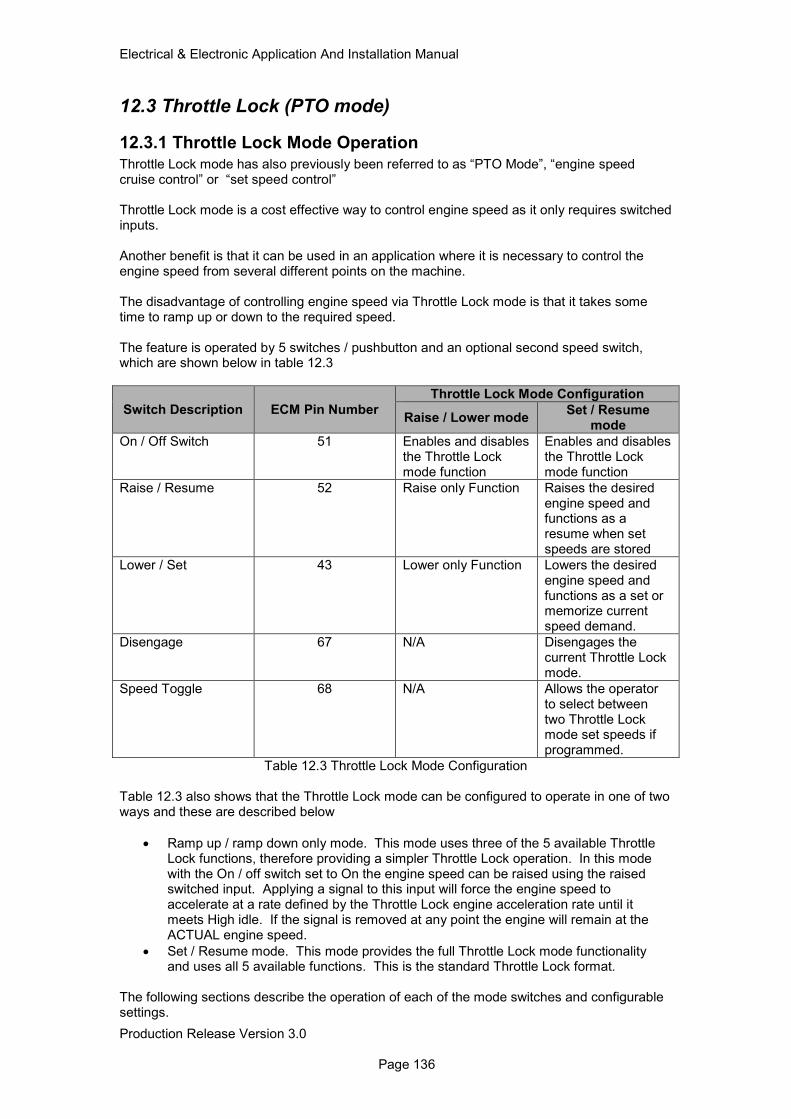
Electrical & Electronic Application And Installation Manual
Production Release Version 3.0 Page 136
12.3 Throttle Lock (PTO mode)
12.3.1 Throttle Lock Mode Operation
Throttle Lock mode has also previously been referred to as “PTO Mode”, “engine speed cruise control” or “set speed control” Throttle Lock mode is a cost effective way to control engine speed as it only requires switched inputs. Another benefit is that it can be used in an application where it is necessary to control the engine speed from several different points on the machine. The disadvantage of controlling engine speed via Throttle Lock mode is that it takes some time to ramp up or down to the required speed. The feature is operated by 5 switches / pushbutton and an optional second speed switch, which are shown below in table 12.3
Switch Description ECM Pin Number
Throttle Lock Mode Configuration
Raise / Lower mode Set / Resume
mode
On / Off Switch 51 Enables and disables the Throttle Lock mode function
Enables and disables the Throttle Lock mode function
Raise / Resume 52 Raise only Function Raises the desired engine speed and functions as a resume when set speeds are stored
Lower / Set 43 Lower only Function Lowers the desired engine speed and functions as a set or memorize current speed demand.
Disengage 67 N/A Disengages the current Throttle Lock mode.
Speed Toggle 68 N/A Allows the operator to select between two Throttle Lock mode set speeds if programmed.
Table 12.3 Throttle Lock Mode Configuration Table 12.3 also shows that the Throttle Lock mode can be configured to operate in one of two ways and these are described below
• Ramp up / ramp down only mode. This mode uses three of the 5 available Throttle Lock functions, therefore providing a simpler Throttle Lock operation. In this mode with the On / off switch set to On the engine speed can be raised using the raised switched input. Applying a signal to this input will force the engine speed to accelerate at a rate defined by the Throttle Lock engine acceleration rate until it meets High idle. If the signal is removed at any point the engine will remain at the ACTUAL engine speed.
• Set / Resume mode. This mode provides the full Throttle Lock mode functionality and uses all 5 available functions. This is the standard Throttle Lock format.
The following sections describe the operation of each of the mode switches and configurable settings.
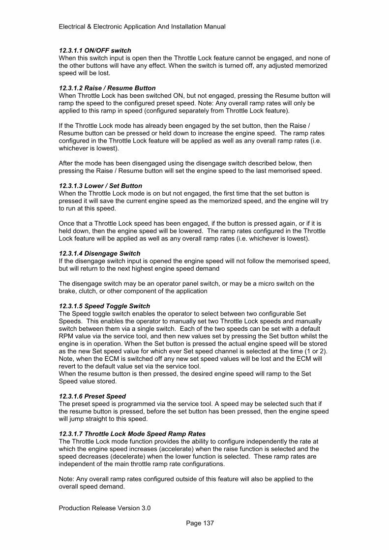
Electrical & Electronic Application And Installation Manual
Production Release Version 3.0 Page 137
12.3.1.1 ON/OFF switch When this switch input is open then the Throttle Lock feature cannot be engaged, and none of the other buttons will have any effect. When the switch is turned off, any adjusted memorized speed will be lost. 12.3.1.2 Raise / Resume Button When Throttle Lock has been switched ON, but not engaged, pressing the Resume button will ramp the speed to the configured preset speed. Note: Any overall ramp rates will only be applied to this ramp in speed (configured separately from Throttle Lock feature). If the Throttle Lock mode has already been engaged by the set button, then the Raise / Resume button can be pressed or held down to increase the engine speed. The ramp rates configured in the Throttle Lock feature will be applied as well as any overall ramp rates (i.e. whichever is lowest). After the mode has been disengaged using the disengage switch described below, then pressing the Raise / Resume button will set the engine speed to the last memorised speed. 12.3.1.3 Lower / Set Button When the Throttle Lock mode is on but not engaged, the first time that the set button is pressed it will save the current engine speed as the memorized speed, and the engine will try to run at this speed. Once that a Throttle Lock speed has been engaged, if the button is pressed again, or if it is held down, then the engine speed will be lowered. The ramp rates configured in the Throttle Lock feature will be applied as well as any overall ramp rates (i.e. whichever is lowest). 12.3.1.4 Disengage Switch If the disengage switch input is opened the engine speed will not follow the memorised speed, but will return to the next highest engine speed demand The disengage switch may be an operator panel switch, or may be a micro switch on the brake, clutch, or other component of the application 12.3.1.5 Speed Toggle Switch The Speed toggle switch enables the operator to select between two configurable Set Speeds. This enables the operator to manually set two Throttle Lock speeds and manually switch between them via a single switch. Each of the two speeds can be set with a default RPM value via the service tool, and then new values set by pressing the Set button whilst the engine is in operation. When the Set button is pressed the actual engine speed will be stored as the new Set speed value for which ever Set speed channel is selected at the time (1 or 2). Note, when the ECM is switched off any new set speed values will be lost and the ECM will revert to the default value set via the service tool. When the resume button is then pressed, the desired engine speed will ramp to the Set Speed value stored. 12.3.1.6 Preset Speed The preset speed is programmed via the service tool. A speed may be selected such that if the resume button is pressed, before the set button has been pressed, then the engine speed will jump straight to this speed. 12.3.1.7 Throttle Lock Mode Speed Ramp Rates The Throttle Lock mode function provides the ability to configure independently the rate at which the engine speed increases (accelerate) when the raise function is selected and the speed decreases (decelerate) when the lower function is selected. These ramp rates are independent of the main throttle ramp rate configurations. Note: Any overall ramp rates configured outside of this feature will also be applied to the overall speed demand.
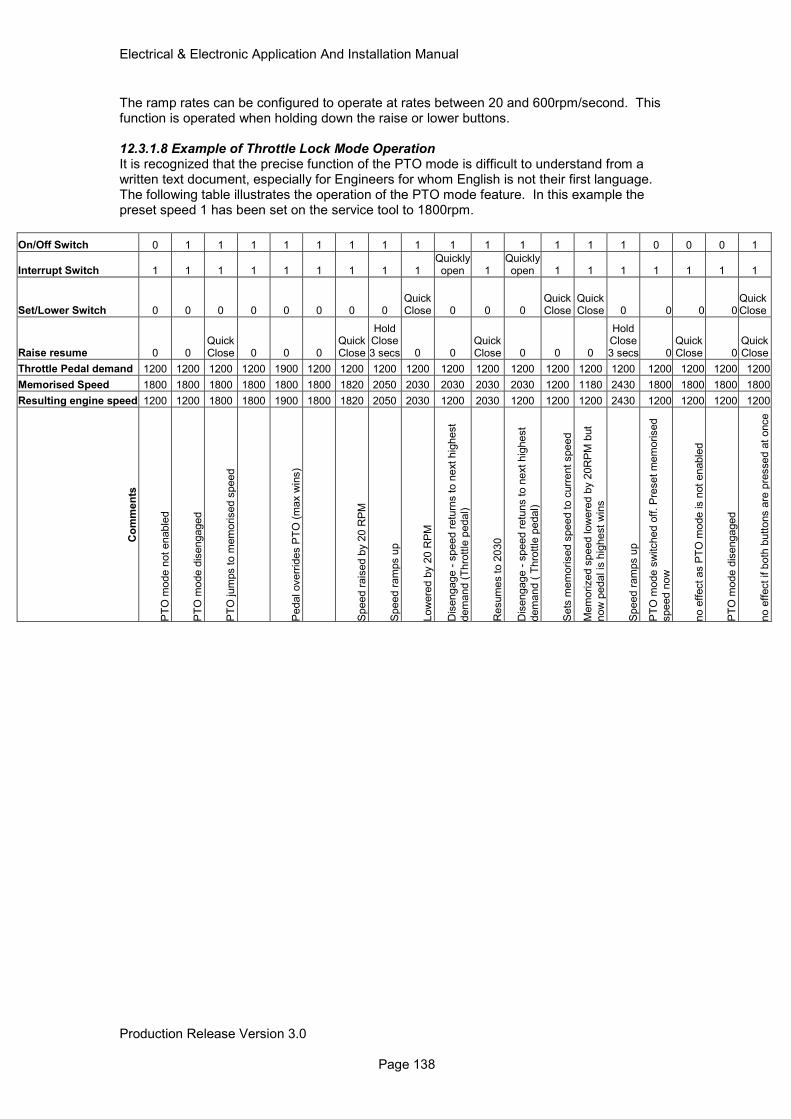
Electrical & Electronic Application And Installation Manual
Production Release Version 3.0 Page 138
The ramp rates can be configured to operate at rates between 20 and 600rpm/second. This function is operated when holding down the raise or lower buttons. 12.3.1.8 Example of Throttle Lock Mode Operation It is recognized that the precise function of the PTO mode is difficult to understand from a written text document, especially for Engineers for whom English is not their first language. The following table illustrates the operation of the PTO mode feature. In this example the preset speed 1 has been set on the service tool to 1800rpm.
On/Off Switch 0 1 1 1 1 1 1 1 1 1 1 1 1 1 1 0 0 0 1
Interrupt Switch 1 1 1 1 1 1 1 1 1 Quickly open 1
Quickly open 1 1 1 1 1 1 1
Set/Lower Switch 0 0 0 0 0 0 0 0 Quick Close 0 0 0
Quick Close
Quick Close 0 0 0 0
Quick Close
Raise resume 0 0 Quick Close 0 0 0
Quick Close
Hold Close 3 secs 0 0
Quick Close 0 0 0
Hold Close 3 secs 0
Quick Close 0
Quick Close
Throttle Pedal demand 1200 1200 1200 1200 1900 1200 1200 1200 1200 1200 1200 1200 1200 1200 1200 1200 1200 1200 1200
Memorised Speed 1800 1800 1800 1800 1800 1800 1820 2050 2030 2030 2030 2030 1200 1180 2430 1800 1800 1800 1800
Resulting engine speed 1200 1200 1800 1800 1900 1800 1820 2050 2030 1200 2030 1200 1200 1200 2430 1200 1200 1200 1200
Co
mm
en
ts
PT
O m
ode n
ot enable
d
PT
O m
ode d
isengaged
PT
O jum
ps to m
em
orised s
peed
Pedal overr
ides P
TO
(m
ax w
ins)
Speed r
ais
ed b
y 2
0 R
PM
Speed r
am
ps u
p
Low
ere
d b
y 2
0 R
PM
Dis
engage -
speed r
etu
rns t
o n
ext hig
hest
dem
and (
Thro
ttle
pedal)
Resum
es t
o 2
030
Dis
engage -
speed r
etu
ns t
o n
ext hig
hest
dem
and (
Thro
ttle
pedal)
Sets
mem
orised s
peed t
o c
urr
ent speed
Mem
orized s
peed low
ere
d b
y 2
0R
PM
but
now
pedal is
hig
hest
win
s
Speed r
am
ps u
p
PT
O m
ode s
witched o
ff. P
reset m
em
orised
speed n
ow
no e
ffect as P
TO
mode is n
ot
enable
d
PT
O m
ode d
isengaged
no e
ffect if b
oth
butt
ons a
re p
ressed a
t once
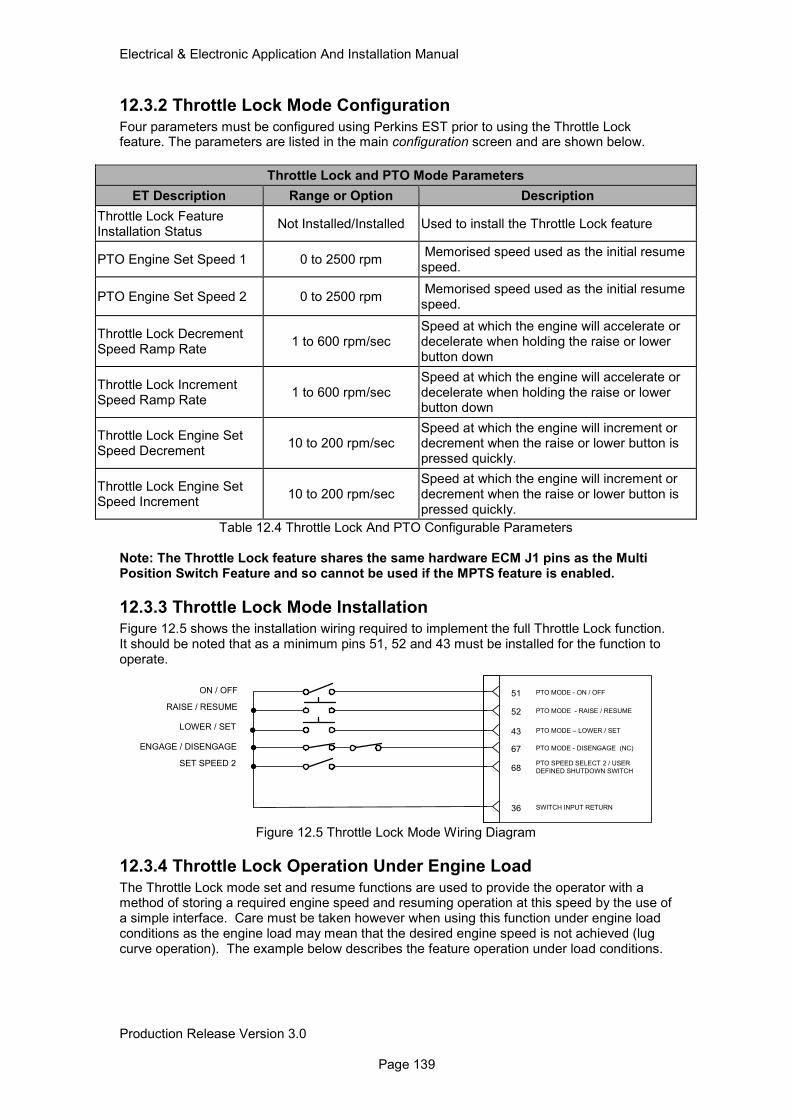
Electrical & Electronic Application And Installation Manual
Production Release Version 3.0 Page 139
12.3.2 Throttle Lock Mode Configuration
Four parameters must be configured using Perkins EST prior to using the Throttle Lock feature. The parameters are listed in the main configuration screen and are shown below.
Throttle Lock and PTO Mode Parameters
ET Description Range or Option Description
Throttle Lock Feature Installation Status
Not Installed/Installed Used to install the Throttle Lock feature
PTO Engine Set Speed 1 0 to 2500 rpm Memorised speed used as the initial resume speed.
PTO Engine Set Speed 2 0 to 2500 rpm Memorised speed used as the initial resume speed.
Throttle Lock Decrement Speed Ramp Rate
1 to 600 rpm/sec Speed at which the engine will accelerate or decelerate when holding the raise or lower button down
Throttle Lock Increment Speed Ramp Rate
1 to 600 rpm/sec Speed at which the engine will accelerate or decelerate when holding the raise or lower button down
Throttle Lock Engine Set Speed Decrement
10 to 200 rpm/sec Speed at which the engine will increment or decrement when the raise or lower button is pressed quickly.
Throttle Lock Engine Set Speed Increment
10 to 200 rpm/sec Speed at which the engine will increment or decrement when the raise or lower button is pressed quickly.
Table 12.4 Throttle Lock And PTO Configurable Parameters
Note: The Throttle Lock feature shares the same hardware ECM J1 pins as the Multi Position Switch Feature and so cannot be used if the MPTS feature is enabled.
12.3.3 Throttle Lock Mode Installation Figure 12.5 shows the installation wiring required to implement the full Throttle Lock function. It should be noted that as a minimum pins 51, 52 and 43 must be installed for the function to operate.
Figure 12.5 Throttle Lock Mode Wiring Diagram
12.3.4 Throttle Lock Operation Under Engine Load
The Throttle Lock mode set and resume functions are used to provide the operator with a method of storing a required engine speed and resuming operation at this speed by the use of a simple interface. Care must be taken however when using this function under engine load conditions as the engine load may mean that the desired engine speed is not achieved (lug curve operation). The example below describes the feature operation under load conditions.
RAISE / RESUME
LOWER / SET
ON / OFF
67 PTO MODE - DISENGAGE (NC)
36 SWITCH INPUT RETURN
43 PTO MODE – LOWER / SET
52 PTO MODE - RAISE / RESUME
51 PTO MODE - ON / OFF
SET SPEED 268
PTO SPEED SELECT 2 / USER
DEFINED SHUTDOWN SWITCH
ENGAGE / DISENGAGE
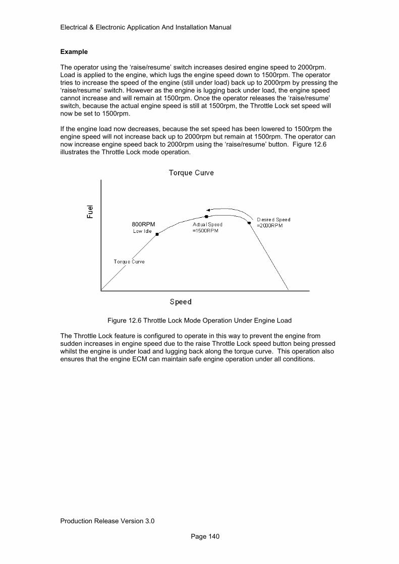
Electrical & Electronic Application And Installation Manual
Production Release Version 3.0 Page 140
Example The operator using the ‘raise/resume’ switch increases desired engine speed to 2000rpm. Load is applied to the engine, which lugs the engine speed down to 1500rpm. The operator tries to increase the speed of the engine (still under load) back up to 2000rpm by pressing the ‘raise/resume’ switch. However as the engine is lugging back under load, the engine speed cannot increase and will remain at 1500rpm. Once the operator releases the ‘raise/resume’ switch, because the actual engine speed is still at 1500rpm, the Throttle Lock set speed will now be set to 1500rpm. If the engine load now decreases, because the set speed has been lowered to 1500rpm the engine speed will not increase back up to 2000rpm but remain at 1500rpm. The operator can now increase engine speed back to 2000rpm using the ‘raise/resume’ button. Figure 12.6 illustrates the Throttle Lock mode operation.
Figure 12.6 Throttle Lock Mode Operation Under Engine Load The Throttle Lock feature is configured to operate in this way to prevent the engine from sudden increases in engine speed due to the raise Throttle Lock speed button being pressed whilst the engine is under load and lugging back along the torque curve. This operation also ensures that the engine ECM can maintain safe engine operation under all conditions.
800RPM
Electrical & Electronic Application And Installation Manual
Production Release Version 3.0 Page 141
12.4 Multi Position Throttle Switch (MPTS)
12.4.1 MPTS Operation
The MPTS feature enables the user to select up to 16 pre-configured speed settings as defined by four throttle switch inputs. These switch inputs can be operated via individual or combined switching devices such as rotary switches. Care should be taken however when selecting switches to ensure that they are break before make. This is a very powerful and flexible feature that may be used in a number of ways. For example:
• Principal speed control method for hydrostatic machines where engine speed is selected and then not required to be frequently changed by the operator. It is in this respect a good alternative to a hand throttle as the speeds selected on the switch. can be designed to correspond to the optimum operating speeds of hydraulic pumps. A rotary encoded 10 position switch component is available for this function. Please contact the electronic applications team for further details.
• Machine limp home speed feature. For example, if the normal throttle fails the operator could remove a fuse or a link and the engine would go to a speed that would allow the machine to be moved. In this application only one of the available 4 switch inputs would be used.
• Elevated idle. For example the OEM could increase the idle speed when work lights are switched on so that the alternator will provide sufficient current to recharge the battery. In this application only one of the available 4 switch inputs would be used.
If a switch combination is detected which has been configured as “Not Valid” then a fault code will be raised (91-2 or 774-2) and the ECM will ignore the MPTS for the rest of the key cycle. 12.4.1.1 Intermediate Speed Function The MPTS function can be installed to provide an intermediate set speed option via pin 43 of the ECM J1 connector. This function gives the option of a single set speed that overrides all other speed requests including TSC1. This function can be activated when required via the switching of input pin 43 to ground. This feature can be used in conjunction with the MPTS, however if both functions are required pin 43 will be dedicated to the intermediate speed function leaving the remaining three inputs for the MPTS function. This will reduce the number of MPTS set speeds available for selection from 16 to 8.
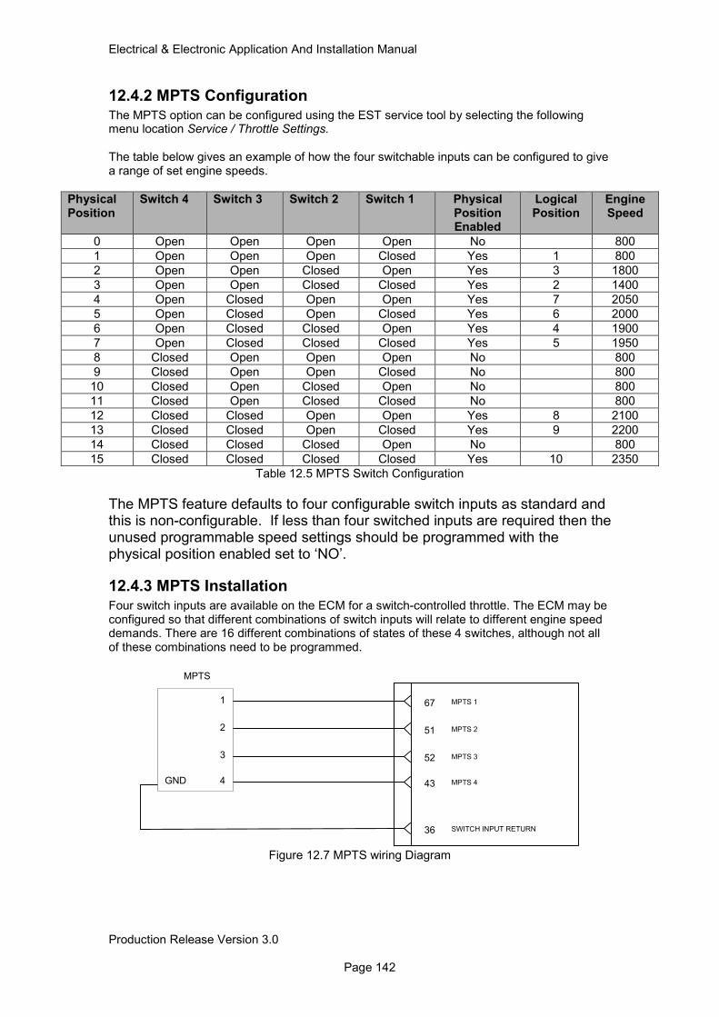
Electrical & Electronic Application And Installation Manual
Production Release Version 3.0 Page 142
12.4.2 MPTS Configuration
The MPTS option can be configured using the EST service tool by selecting the following menu location Service / Throttle Settings. The table below gives an example of how the four switchable inputs can be configured to give a range of set engine speeds.
Physical Position
Switch 4 Switch 3 Switch 2 Switch 1 Physical Position Enabled
Logical Position
Engine Speed
0 Open Open Open Open No 800
1 Open Open Open Closed Yes 1 800
2 Open Open Closed Open Yes 3 1800
3 Open Open Closed Closed Yes 2 1400
4 Open Closed Open Open Yes 7 2050
5 Open Closed Open Closed Yes 6 2000
6 Open Closed Closed Open Yes 4 1900
7 Open Closed Closed Closed Yes 5 1950
8 Closed Open Open Open No 800
9 Closed Open Open Closed No 800
10 Closed Open Closed Open No 800
11 Closed Open Closed Closed No 800
12 Closed Closed Open Open Yes 8 2100
13 Closed Closed Open Closed Yes 9 2200
14 Closed Closed Closed Open No 800
15 Closed Closed Closed Closed Yes 10 2350
Table 12.5 MPTS Switch Configuration
The MPTS feature defaults to four configurable switch inputs as standard and this is non-configurable. If less than four switched inputs are required then the unused programmable speed settings should be programmed with the physical position enabled set to ‘NO’.
12.4.3 MPTS Installation
Four switch inputs are available on the ECM for a switch-controlled throttle. The ECM may be configured so that different combinations of switch inputs will relate to different engine speed demands. There are 16 different combinations of states of these 4 switches, although not all of these combinations need to be programmed.
43 MPTS 4
36 SWITCH INPUT RETURN
52 MPTS 3
51 MPTS 2
67 MPTS 1
MPTS
1
2
3
4GND
Figure 12.7 MPTS wiring Diagram
Electrical & Electronic Application And Installation Manual
Production Release Version 3.0 Page 143
12.5 Torque Speed Control TSC1 (Speed Control Over CAN) A special J1939 message called Torque/Speed Control #1 (TSC1) allows other electronic devices to control or to limit the engine speed. This message is explained in detail in section 20 of this application and installation guide.
12.6 Arbitration of speed demand In applications where there is more than one source of engine speed demand, it is necessary to arbitrate between the different demands. The speed arbitration does not apply to the PTO or J1939 TSC1 speed demand features. There are 4 methods of arbitration:
• Max Wins. The highest speed demand is the one that controls the engine. This is the default configuration
• Manual Selection switch. A switch input can be used to define which speed input has control. This is particularly useful in applications where there are 2 driver seat positions.
• Intermediate engine speed switch. Used as part of the MPTS function but will override all speed demands when operated including TSC1.
• Lowest wins. In this case the low engine speed demanded will be the overall speed selected.
Note: TSC1 will override speed demands from all sources other than Intermediate engine speed switch when activated.
12.6.1 Manual Throttle Selection Switch
A switch input is available on pin 66 of the ECM J1 connector, which can be configured to manually select the active speed demand channel. If the switch is configured for use (this must be done using the EST service tool), then if the switch input is open, speed demand 1 is selected. If the switch is closed, speed demand 2 is selected.
12.7 Acceleration and Deceleration Ramp Rates It is possible to limit the overall acceleration rate of the engine speed. The acceleration limit applies to overall engine speed, irrespective of applied strategy. The rate may be configured using EST. The rate is defined in units of rpm per second. 0 rpm/s represents no limit to engine acceleration (i.e. turns off the feature.) The default ramp rate will be 0 rpm/s. When ramp rates are being used within the PTO function it should be noted that if overall acceleration and deceleration ramp rates are also being used the engine software will apply the lower of the two values.
12.8 Throttle Behaviour During Engine Governor Changes To protect the engine and drivetrain system during engine governor selection changes, interlocks between engine speed demand and governor mode have been employed. When changing between governor modes via the mode switches or J1939 message, the following throttle features are enabled / disabled.
Governor Mode PTO Mode Availability
MPTS Availability
All Speed Governing Yes Yes
Min / Max Governing No No
Table 12.6 Throttle Features and Governor Compatibility
To switch between engine governing modes the actual engine speed must be returned to its low idle setting under all circumstances. If this condition is not met then the governor mode will not change regardless of the switched input state. For more information on engine governing and it’s configuration please refer to section 16 of this document.
Electrical & Electronic Application And Installation Manual
Production Release Version 3.0 Page 144
12.9 Engine Limp Home Speed The engine limp home speed setting is a configurable default engine speed to which the engine controls in the event of a throttle pedal failure. This limp home speed is configurable using ET to a value between 800rpm and 1800rpm. The default value is set to 1200rpm. It is recommended that the limp home speed is set to a different value than the engine low idle. This ensures that in addition to an engine diagnostic code there is a clear indication to the operator that the throttle signal has been lost. In addition the limp home speed is usually set to allow the machine to be placed into a safe condition / area for re-work to take place. In the event of an engine throttle failure the engine is designed to behave as follows; If actual engine speed is above limp home speed when throttle fault occurs the actual engine speed will default to the configured limp home speed. If actual engine speed is below the limp home speed when throttle fault occurs the actual engine speed will default to the configured low idle speed.
12.10 Throttle Calibration The majority of throttle components have mechanical and electrical tolerances that affect the final output of a device, for example two components of the same design and part number may produce a different voltage output in the open position. Also after a period of time throttle components can mechanically wear, affecting/changing the output of a device. To accommodate these differences and changes the engine ECM may be configured to automatically calibrate to differing input values at the upper and lower positions. The diagrams below give an example pedal design where the open and closed position of the throttle pedal are set by adjusting the manufacturing adjustment screws. With this type of arrangement the mechanical accuracy is limited and therefore auto calibration may be used. The calibration control logic needs a number of parameters specific to the chosen device to allow auto calibration. This feature is configurable for Analogue and PWM inputs. The algorithm treats either a PWM or analogue input as a ‘raw signal’ in the range 0 to 100% for example the analogue voltage range is 5V therefore 0.05V is treated as 1%. Several parameters are used to:
• Define the boundaries for calibration in the open and closed positions
• Define the amount of ‘deadzone /play’ from the open and closed positions
• Define the upper and lower diagnostic boundaries
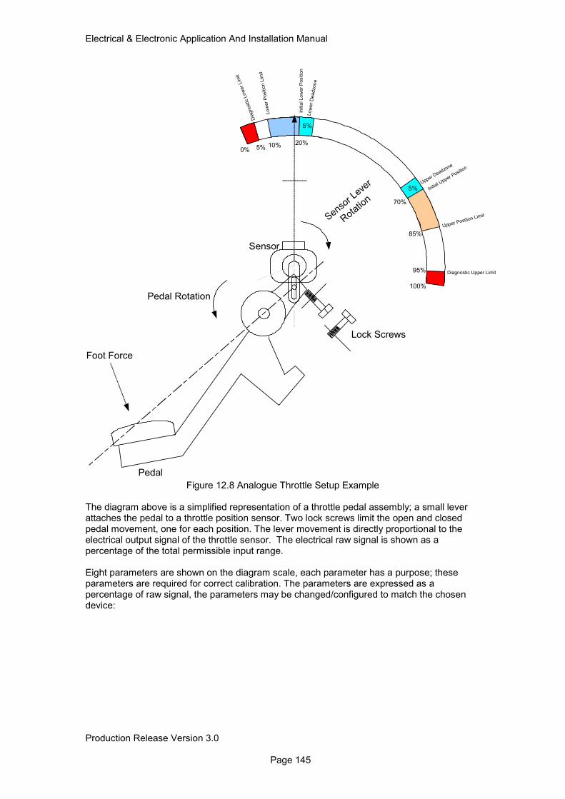
Electrical & Electronic Application And Installation Manual
Production Release Version 3.0 Page 145
Lo
wer
Positio
n L
imit
Initia
l Lo
wer
Positio
n
Low
er
Deadzone
Diagnostic Upper Limit
Upper Position Limit
Initial U
pper Positio
n
Dia
gnostic
Low
er
Lim
it
Upper Deadzo
ne
0%
100%
10% 20%
70%
85%
5%
95%
5%
5%
Pedal Rotation
Sensor L
ever
Rotatio
n
Lock Screws
Pedal
Sensor
Foot Force
Figure 12.8 Analogue Throttle Setup Example The diagram above is a simplified representation of a throttle pedal assembly; a small lever attaches the pedal to a throttle position sensor. Two lock screws limit the open and closed pedal movement, one for each position. The lever movement is directly proportional to the electrical output signal of the throttle sensor. The electrical raw signal is shown as a percentage of the total permissible input range. Eight parameters are shown on the diagram scale, each parameter has a purpose; these parameters are required for correct calibration. The parameters are expressed as a percentage of raw signal, the parameters may be changed/configured to match the chosen device:
Electrical & Electronic Application And Installation Manual
Production Release Version 3.0 Page 146
12.10.1 Throttle Parameter Description Diagnostic Lower Limit The lower diagnostic limit is the absolute minimum raw value accepted as a valid signal by the engine ECM. Any values below this point will flag appropriate diagnostics and invoke the limp-home strategy. Most analogue devices are classed as faulted with a voltage of 0.25V and below (5%) this is to prevent a possible open or short circuit being mistaken for a valid signal, for similar reasons a PWM duty cycle should not fall below 5% duty cycle. Lower Position limit This is the minimum point of the lower calibration boundary Initial Lower Position limit This is the maximum point of the lower calibration boundary. This value is also used as the initial lower position when no calibration has been applied. Lower Deadzone This position is given as a discrete raw signal percentage value. The lower dead zone effectively gives some play at the lower position. This dead band is expressed in terms of a raw signal percentage, such that the initial lower position plus the lower dead zone will give the 0% throttle position. Initial Upper Position limit This is the minimum point of the upper calibration boundary. This value is also used as the initial upper position when no calibration has been applied. Upper Position Limit This is the maximum point of the upper calibration boundary Upper Deadzone This position is given as a discrete raw signal percentage value. The upper dead zone effectively gives some play at the upper position. This dead band is expressed in terms of a raw signal percentage, such that the initial upper position minus the upper dead zone will give the 100% throttle position. Diagnostic Upper Limit The upper diagnostic limit is the absolute maximum raw value accepted as a valid signal by the engine ECM. Any values above this point will flag appropriate diagnostics and invoke the limp-home strategy. Most analogue devices are classed as faulted with a voltage of 4.75V and above, this is to prevent a possible open or short circuit being mistaken for a valid signal, for similar reasons a PWM duty cycle should not go above 95% duty cycle.
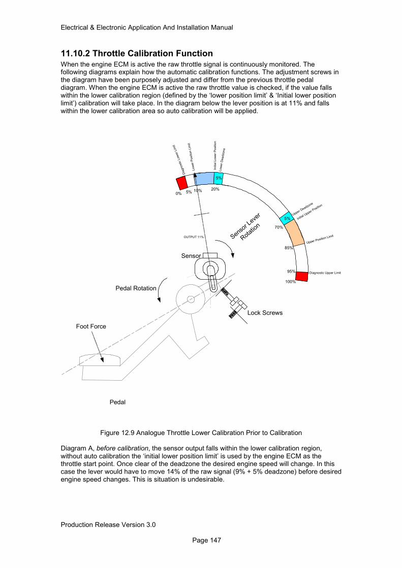
Electrical & Electronic Application And Installation Manual
Production Release Version 3.0 Page 147
11.10.2 Throttle Calibration Function
When the engine ECM is active the raw throttle signal is continuously monitored. The following diagrams explain how the automatic calibration functions. The adjustment screws in the diagram have been purposely adjusted and differ from the previous throttle pedal diagram. When the engine ECM is active the raw throttle value is checked, if the value falls within the lower calibration region (defined by the ‘lower position limit’ & ‘Initial lower position limit’) calibration will take place. In the diagram below the lever position is at 11% and falls within the lower calibration area so auto calibration will be applied.
Low
er
Positio
n L
imit
Initia
l L
ow
er
Po
sitio
n
Low
er
Dea
dzo
ne
Diagnostic Upper Limit
Upper Position Limit
Initial U
pper Posit
ion
Dia
gnostic
Low
er
Lim
it
Upper Deadzo
ne
0%
100%
10% 20%
70%
85%
5%
95%
5%
5%
Pedal Rotation
Sensor L
ever
Rotat
ion
Lock Screws
Pedal
Sensor
Foot Force
OUTPUT 11%
Figure 12.9 Analogue Throttle Lower Calibration Prior to Calibration Diagram A, before calibration, the sensor output falls within the lower calibration region, without auto calibration the ‘initial lower position limit’ is used by the engine ECM as the throttle start point. Once clear of the deadzone the desired engine speed will change. In this case the lever would have to move 14% of the raw signal (9% + 5% deadzone) before desired engine speed changes. This is situation is undesirable.
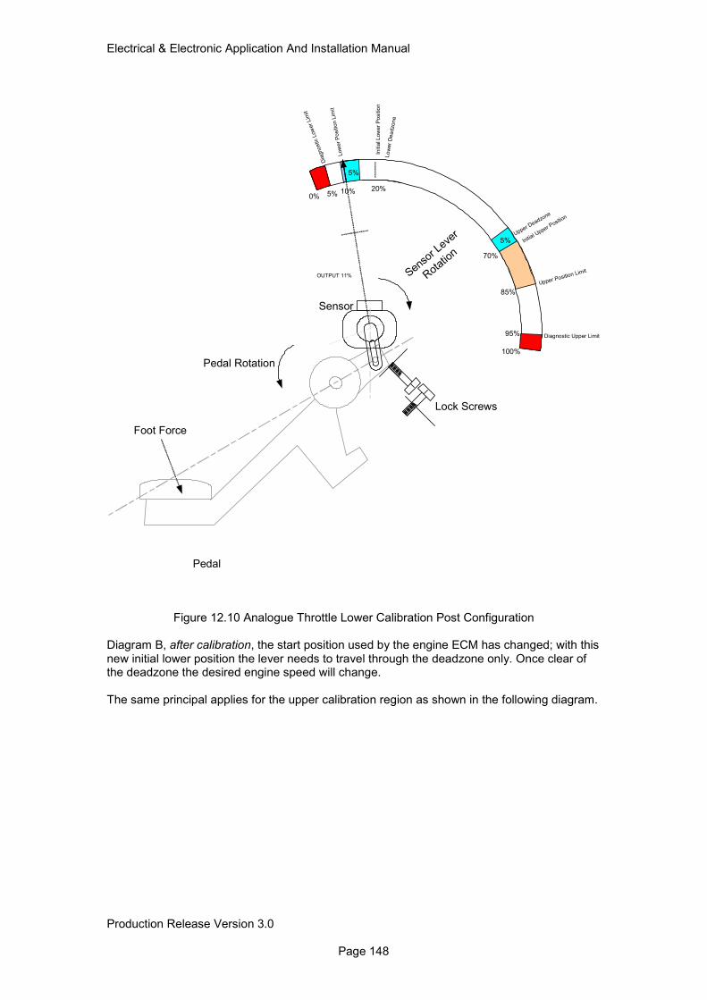
Electrical & Electronic Application And Installation Manual
Production Release Version 3.0 Page 148
Low
er
Positio
n L
imit
Initia
l L
ow
er
Po
sitio
n
Low
er
Dea
dzo
ne
Diagnostic Upper Limit
Upper Position Limit
Initial U
pper Posit
ion
Dia
gnostic
Low
er
Lim
it
Upper Deadzo
ne
0%
100%
10% 20%
70%
85%
5%
95%
5%
5%
Pedal Rotation
Sensor L
ever
Rotat
ion
Lock Screws
Pedal
Sensor
Foot Force
OUTPUT 11%
Figure 12.10 Analogue Throttle Lower Calibration Post Configuration Diagram B, after calibration, the start position used by the engine ECM has changed; with this new initial lower position the lever needs to travel through the deadzone only. Once clear of the deadzone the desired engine speed will change. The same principal applies for the upper calibration region as shown in the following diagram.
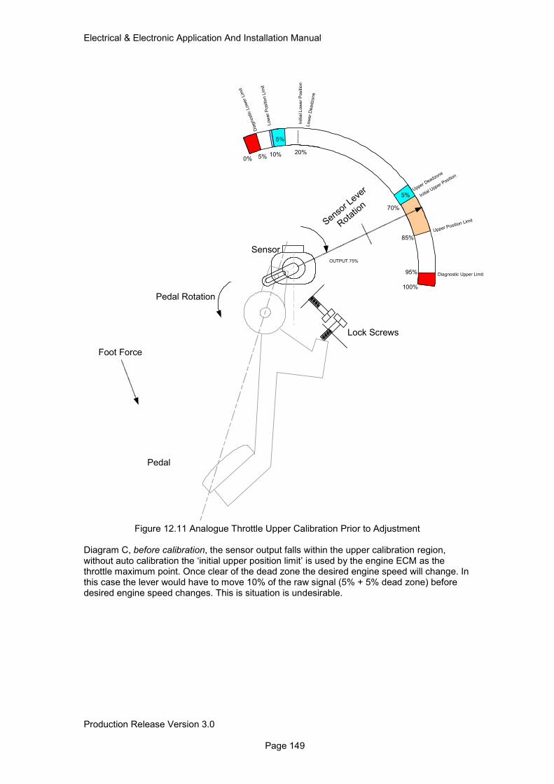
Electrical & Electronic Application And Installation Manual
Production Release Version 3.0 Page 149
Low
er
Positio
n L
imit
Initia
l L
ow
er
Positio
n
Low
er
Dea
dzone
Diagnostic Upper Limit
Upper Position Limit
Initial U
pper Positio
n
Dia
gnostic L
ow
er
Lim
it
Upper Deadzone
0%
100%
10% 20%
70%
85%
5%
95%
5%
5%
Pedal Rotation
Sensor L
ever
Rota
tion
Lock Screws
Pedal
Sensor
Foot Force
OUTPUT 75%
Figure 12.11 Analogue Throttle Upper Calibration Prior to Adjustment Diagram C, before calibration, the sensor output falls within the upper calibration region, without auto calibration the ‘initial upper position limit’ is used by the engine ECM as the throttle maximum point. Once clear of the dead zone the desired engine speed will change. In this case the lever would have to move 10% of the raw signal (5% + 5% dead zone) before desired engine speed changes. This is situation is undesirable.
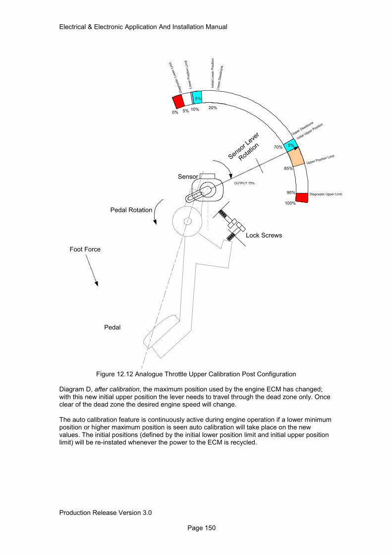
Electrical & Electronic Application And Installation Manual
Production Release Version 3.0 Page 150
Low
er
Positio
n L
imit
Initia
l L
ow
er
Positio
n
Low
er
Dea
dzone
Diagnostic Upper Limit
Upper Position Limit
Initial U
pper Positio
n
Dia
gnostic L
ow
er
Lim
it
Upper Deadzone
0%
100%
10% 20%
70%
85%
5%
95%
5%
5%
Pedal Rotation
Sensor L
ever
Rota
tion
Lock Screws
Pedal
Sensor
Foot Force
OUTPUT 75%
Figure 12.12 Analogue Throttle Upper Calibration Post Configuration Diagram D, after calibration, the maximum position used by the engine ECM has changed; with this new initial upper position the lever needs to travel through the dead zone only. Once clear of the dead zone the desired engine speed will change. The auto calibration feature is continuously active during engine operation if a lower minimum position or higher maximum position is seen auto calibration will take place on the new values. The initial positions (defined by the initial lower position limit and initial upper position limit) will be re-instated whenever the power to the ECM is recycled.
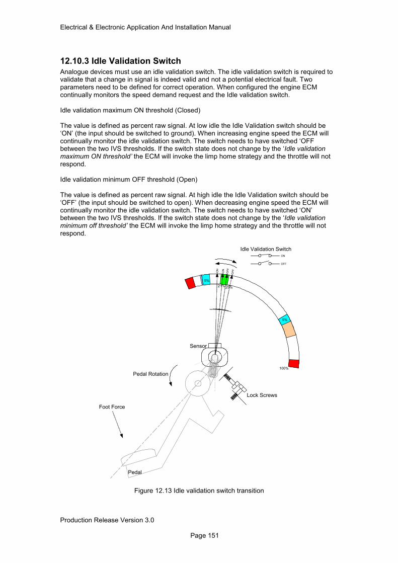
Electrical & Electronic Application And Installation Manual
Production Release Version 3.0 Page 151
12.10.3 Idle Validation Switch
Analogue devices must use an idle validation switch. The idle validation switch is required to validate that a change in signal is indeed valid and not a potential electrical fault. Two parameters need to be defined for correct operation. When configured the engine ECM continually monitors the speed demand request and the Idle validation switch. Idle validation maximum ON threshold (Closed) The value is defined as percent raw signal. At low idle the Idle Validation switch should be ‘ON’ (the input should be switched to ground). When increasing engine speed the ECM will continually monitor the idle validation switch. The switch needs to have switched ‘OFF between the two IVS thresholds. If the switch state does not change by the ‘Idle validation maximum ON threshold’ the ECM will invoke the limp home strategy and the throttle will not respond. Idle validation minimum OFF threshold (Open) The value is defined as percent raw signal. At high idle the Idle Validation switch should be ‘OFF’ (the input should be switched to open). When decreasing engine speed the ECM will continually monitor the idle validation switch. The switch needs to have switched ‘ON’ between the two IVS thresholds. If the switch state does not change by the ‘Idle validation minimum off threshold’ the ECM will invoke the limp home strategy and the throttle will not respond.
100%
5%
5%
Pedal Rotation
Lock Screws
Pedal
Sensor
Foot Force
21%25%
Idle Validation Switch
ON
OF
F
ON
OF
F
ON
OFF
Figure 12.13 Idle validation switch transition
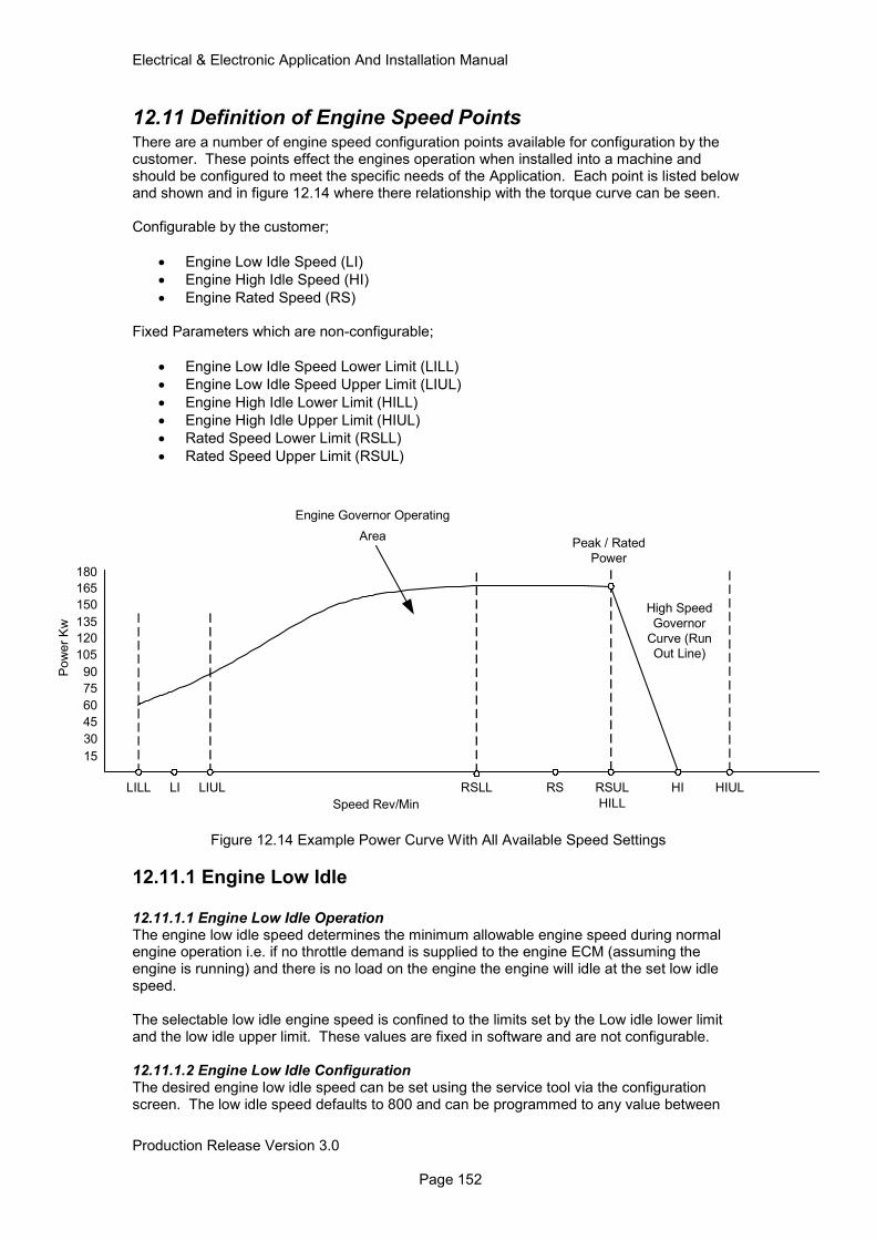
Electrical & Electronic Application And Installation Manual
Production Release Version 3.0 Page 152
12.11 Definition of Engine Speed Points There are a number of engine speed configuration points available for configuration by the customer. These points effect the engines operation when installed into a machine and should be configured to meet the specific needs of the Application. Each point is listed below and shown and in figure 12.14 where there relationship with the torque curve can be seen. Configurable by the customer;
• Engine Low Idle Speed (LI)
• Engine High Idle Speed (HI)
• Engine Rated Speed (RS) Fixed Parameters which are non-configurable;
• Engine Low Idle Speed Lower Limit (LILL)
• Engine Low Idle Speed Upper Limit (LIUL)
• Engine High Idle Lower Limit (HILL)
• Engine High Idle Upper Limit (HIUL)
• Rated Speed Lower Limit (RSLL)
• Rated Speed Upper Limit (RSUL)
Figure 12.14 Example Power Curve With All Available Speed Settings
12.11.1 Engine Low Idle
12.11.1.1 Engine Low Idle Operation The engine low idle speed determines the minimum allowable engine speed during normal engine operation i.e. if no throttle demand is supplied to the engine ECM (assuming the engine is running) and there is no load on the engine the engine will idle at the set low idle speed. The selectable low idle engine speed is confined to the limits set by the Low idle lower limit and the low idle upper limit. These values are fixed in software and are not configurable. 12.11.1.2 Engine Low Idle Configuration The desired engine low idle speed can be set using the service tool via the configuration screen. The low idle speed defaults to 800 and can be programmed to any value between
15
30
45
60
75
90
105
120
135
150
165
180
Pow
er
Kw
Speed Rev/Min
Peak / Rated
Power
RSULRSRSLL
HILL
HI HIULLILILL LIUL
High Speed
Governor
Curve (Run
Out Line)
Engine Governor Operating
Area
Electrical & Electronic Application And Installation Manual
Production Release Version 3.0 Page 153
800 and 1200 step size of 10 rpm. If a low idle setting of less than 800rpm is required then please contact the Electronic Applications Engineering department.
12.11.2 Engine High Idle 12.11.2.1 Engine High Idle Operation The engine high idle speed determines the engine full throttle desired engine speed value. As with the low idle setting this parameter is configurable by the customer and can be set to an engine speed limited by the fixed software limits High Idle Lower Limit (HILL) and High Idle Upper Limit (HIUL). The high idle speed setting also works in conjunction with the Rated speed Setting (RS) to determine the high Speed Governor (HSG) run out line. Varying the Rated speed and High Idle settings can alter the gradient of this line and the resulting governor response. Note: For more information regarding the interaction between the RS and HI settings along with the HSG please refer to section 17. Note: Under some circumstances the engine may not be able to reach the desired HI setting under full throttle conditions due to machine torque requirement at this speed. 12.11.2.2 Engine High Idle configuration The desired engine High Idle Speed can be set using the service tool via the configuration screen. The engine High Idle speed defaults to rated speed and can be adjusted to a value between HILL and HIUL. As previously stated the relationship between High Idle and Rated Speed is not mutually exclusive for this reason HILL is set to RS and HIUL is RS + 12%. This means that the max HI setting available for any engine is RS + 12%.
12.11.3 Engine Rated Speed
12.11.3.1 Engine Rated Speed Operation The engine rated speed determines the point at which the High speed governor cuts in. This speed setting is normally pre-defined as the point at which the maximum engine power is obtained (normally set to 2200rpm). In many cases this value is fixed due to the specific rating development. However some ratings do offer the possibility of adjusting the engine rated speed within the limits of the Rated Speed Lower Limit and the rated Speed Upper limit. The values are set within the engine software and are non-configurable. It should be noted that for those ratings, which support the configuration of the engine rated speed, the power and torque produced by the engine across the adjustable speed range is not always constant. For this reason a thorough investigation into the applications power and torque requirement compared to that given by the engine at the new rated speed point must be made. Consideration must also be made to the availability of Torque back-up when reducing the engines rated speed. 12.11.3.2 Engine Rated speed Configuration The configuration of the engine Rated Speed setting can be made using the service tool (only for those engine ratings supporting this feature) via the engine mode selection feature. Please refer to 16.0 Engine Governor for more information on the configuration and use of the engine mode selection feature. The Engine rated speed for those engine ratings supporting the feature can be configured to limits set by the RSLL (1800rpm) and RSUL (2200rpm). These are fixed limits set within the engine software and cannot be altered.

Electrical & Electronic Application And Installation Manual
Production Release Version 3.0 Page 154
13.0 Cold Weather Engine Operation & Starting Aids There are two types of start aid available for all Tier 4 engines, they are, glow plugs (fitted as standard to all engines) and ether (customer configurable option). Engines can be purchased with both start aids enabled however it should be noted that under no circumstances will the glow plugs and ether system be used in conjunction with one another for safety reasons. In general the following applies;
• Glow plugs are only used below +5°C
• Ether start activation is based on temperature and barometric pressure but in general will activate at temperatures below –25°C
When selecting both start aids the control shown in figure 13.1 applies.
Electrical & Electronic Application And Installation Manual
Production Release Version 3.0 Page 155
Figure 13.1 ECM Start Aid Control
Start Aid Control
Engine Coolant Temperature Sensor
Intake Manifold air temperature
Key ON
N
Coolant Temp
Inta
ke T
em
p
Tim
e
ECM activates
Wait to
Start Lamp
and Glow Plugs
for period
determined from
Pre-heat map
N
Engine speed >= to
low idle -200 rpm?
ECM activates
Glow Plugs for
Post-start period
of 15 seconds
Start Aid End
Pre-heat map
ECM selects
coldest
temperature
Y
ECM activates
Glow Plugs during
cranking for
maximum of 10 sec
The operator should wait
until after the Pre-heat period
before cranking. The Glow
Plugs will remain off after the
Pre-heat period until the
engine is cranked
N
Operator crank
engine when lamp
turns off
No Start Aid required
Typical Values (May Vary)
Air Inlet Temperature
Temperature
<= +5 degC ?
Temperature
<=-25 degC?
Operator Cranks
the Engine
Engine ECM
Initiates Ether
dosing
ECM activates
Ether for Post
engine start
duration
Engine Speed within
50rpm of LI
?
?
Typical Values (May Vary) Not yet
defined!
Tim
e
Y
Y
N

Electrical & Electronic Application And Installation Manual
Production Release Version 3.0 Page 156
13.1 Control of Glow Plugs by the Engine ECM
13.1.1 Glow Plug System Operation
Glow plugs are fitted as standard to all Tier 4 Final/Stage IV engines. When the ignition keyswitch is on, the engine ECM will monitor the coolant temperature and the inlet air temperature and decide whether the glow plugs are required. If so, the ECM will activate the glow plug relay and supply current to the engine glow plugs. On a cold start when the ECM decides that it is necessary for the glow plugs to be activated prior to starting, a lamp output will indicate to the operator that they need to ‘wait to start’. Note that it is possible that the start aids will also be used either during cranking or when the engine has started. Under these conditions however the lamp will not be active. The control strategy for start aid control is shown in figure 13.2
Electrical & Electronic Application And Installation Manual
Production Release Version 3.0 Page 157
Figure 13.2 ECM Glow Plug Control
Start Aid Control
Engine Coolant Temperature Sensor
Intake Manifold air temperature
Temperature
<= +5 degC ?
Key ON
N
Coolant Temp
Inta
ke
Te
mp
Tim
e
ECM activates
Wait to
Start Lamp
and Glow Plugs
for period
determined from
Pre-heat map
Y
Engine speed >= to
low idle -200 rpm?
ECM activates
Glow Plugs for
Post-start period
of 15 seconds
Start Aid End
Pre-heat map
ECM selects
coldest
temperature
Y
ECM activates
Glow Plugs during
cranking for
maximum of 10 sec
The operator should wait
until after the Pre-heat period
before cranking. The Glow
Plugs will remain off after the
Pre-heat period until the
engine is cranked
N
Operator crank
engine when lamp
turns off
No Start Aid required
Typical Values (May Vary)
Air Inlet Temperature
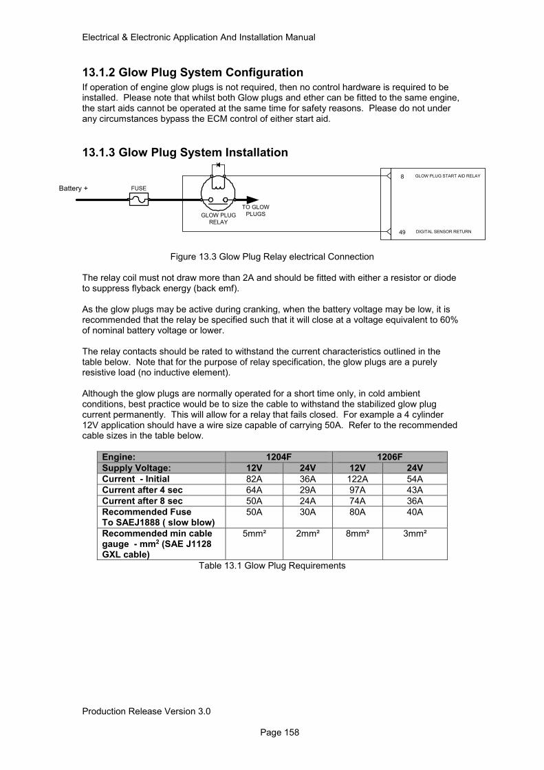
Electrical & Electronic Application And Installation Manual
Production Release Version 3.0 Page 158
13.1.2 Glow Plug System Configuration
If operation of engine glow plugs is not required, then no control hardware is required to be installed. Please note that whilst both Glow plugs and ether can be fitted to the same engine, the start aids cannot be operated at the same time for safety reasons. Please do not under any circumstances bypass the ECM control of either start aid.
13.1.3 Glow Plug System Installation
Figure 13.3 Glow Plug Relay electrical Connection
The relay coil must not draw more than 2A and should be fitted with either a resistor or diode to suppress flyback energy (back emf). As the glow plugs may be active during cranking, when the battery voltage may be low, it is recommended that the relay be specified such that it will close at a voltage equivalent to 60% of nominal battery voltage or lower. The relay contacts should be rated to withstand the current characteristics outlined in the table below. Note that for the purpose of relay specification, the glow plugs are a purely resistive load (no inductive element). Although the glow plugs are normally operated for a short time only, in cold ambient conditions, best practice would be to size the cable to withstand the stabilized glow plug current permanently. This will allow for a relay that fails closed. For example a 4 cylinder 12V application should have a wire size capable of carrying 50A. Refer to the recommended cable sizes in the table below.
Engine: 1204F 1206F
Supply Voltage: 12V 24V 12V 24V
Current - Initial 82A 36A 122A 54A
Current after 4 sec 64A 29A 97A 43A
Current after 8 sec 50A 24A 74A 36A
Recommended Fuse To SAEJ1888 ( slow blow)
50A 30A 80A 40A
Recommended min cable gauge - mm2 (SAE J1128 GXL cable)
5mm² 2mm² 8mm² 3mm²
Table 13.1 Glow Plug Requirements
8 GLOW PLUG START AID RELAY
TO GLOW
PLUGSGLOW PLUG
RELAY
49 DIGITAL SENSOR RETURN
FUSEBattery +

Electrical & Electronic Application And Installation Manual
Production Release Version 3.0 Page 159
To ensure the correct operation of the cold start strategy it is recommended that customer selected relay meets the specification shown below.
Parameter Specification Requirements
Temperature Limit -40°C To +85°C
Vibration Limit 10Grms
Coil Hold In current < 2Amps
N/O Contact Current See table 12.1
Suppression Diode
Table 13.2 Glow Plug Relay Specification Note: All relays must be mounted off engine to reduce the risk of component failure due to engine vibration.
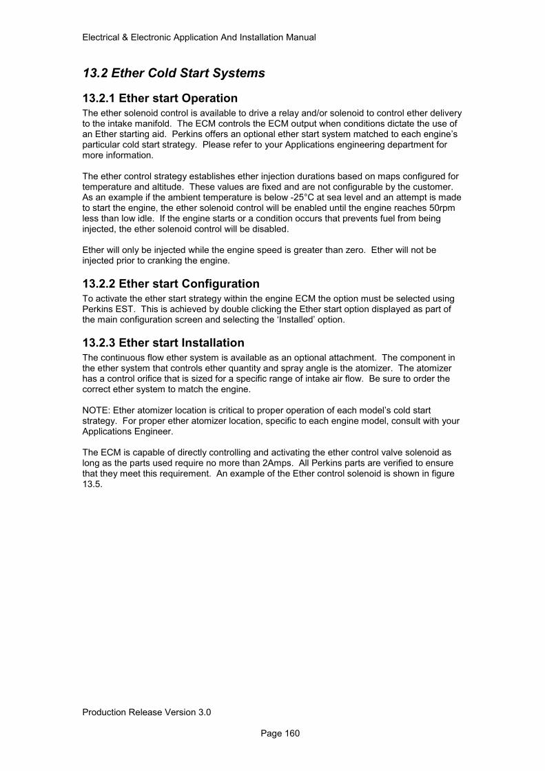
Electrical & Electronic Application And Installation Manual
Production Release Version 3.0 Page 160
13.2 Ether Cold Start Systems
13.2.1 Ether start Operation
The ether solenoid control is available to drive a relay and/or solenoid to control ether delivery to the intake manifold. The ECM controls the ECM output when conditions dictate the use of an Ether starting aid. Perkins offers an optional ether start system matched to each engine’s particular cold start strategy. Please refer to your Applications engineering department for more information. The ether control strategy establishes ether injection durations based on maps configured for temperature and altitude. These values are fixed and are not configurable by the customer. As an example if the ambient temperature is below -25°C at sea level and an attempt is made to start the engine, the ether solenoid control will be enabled until the engine reaches 50rpm less than low idle. If the engine starts or a condition occurs that prevents fuel from being injected, the ether solenoid control will be disabled. Ether will only be injected while the engine speed is greater than zero. Ether will not be injected prior to cranking the engine.
13.2.2 Ether start Configuration
To activate the ether start strategy within the engine ECM the option must be selected using Perkins EST. This is achieved by double clicking the Ether start option displayed as part of the main configuration screen and selecting the ‘Installed’ option.
13.2.3 Ether start Installation
The continuous flow ether system is available as an optional attachment. The component in the ether system that controls ether quantity and spray angle is the atomizer. The atomizer has a control orifice that is sized for a specific range of intake air flow. Be sure to order the correct ether system to match the engine. NOTE: Ether atomizer location is critical to proper operation of each model’s cold start strategy. For proper ether atomizer location, specific to each engine model, consult with your Applications Engineer. The ECM is capable of directly controlling and activating the ether control valve solenoid as long as the parts used require no more than 2Amps. All Perkins parts are verified to ensure that they meet this requirement. An example of the Ether control solenoid is shown in figure 13.5.
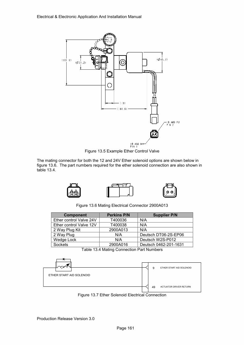
Electrical & Electronic Application And Installation Manual
Production Release Version 3.0 Page 161
Figure 13.5 Example Ether Control Valve The mating connector for both the 12 and 24V Ether solenoid options are shown below in figure 13.6. The part numbers required for the ether solenoid connection are also shown in table 13.4.
Figure 13.6 Mating Electrical Connector 2900A013
Component Perkins P/N Supplier P/N
Ether control Valve 24V T400036 N/A
Ether control Valve 12V T400038 N/A
2 Way Plug Kit 2900A013 N/A
2 Way Plug N/A Deutsch DT06-2S-EP06
Wedge Lock N/A Deutsch W2S-P012
Sockets 2900A016 Deutsch 0462-201-1631
Table 13.4 Mating Connection Part Numbers
Figure 13.7 Ether Solenoid Electrical Connection
9 ETHER START AID SOLENOID
ETHER START AID SOLENOID
49 ACTUATOR DRIVER RETURN
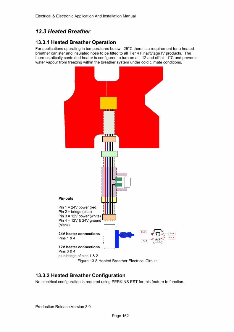
Electrical & Electronic Application And Installation Manual
Production Release Version 3.0 Page 162
13.3 Heated Breather
13.3.1 Heated Breather Operation
For applications operating in temperatures below –25°C there is a requirement for a heated breather canister and insulated hose to be fitted to all Tier 4 Final/Stage IV products. The thermostatically controlled heater is configured to turn on at –12 and off at –1°C and prevents water vapour from freezing within the breather system under cold climate conditions.
Figure 13.8 Heated Breather Electrical Circuit
13.3.2 Heated Breather Configuration No electrical configuration is required using PERKINS EST for this feature to function.
Pin 1
Pin 2
Pin 3
Pin 4
Pin-outs
Pin 1 = 24V power (red)
Pin 2 = bridge (blue)
Pin 3 = 12V power (white)
Pin 4 = 12V & 24V ground
(black)
24V heater connections
Pins 1 & 4
12V heater connections
Pins 3 & 4
plus bridge of pins 1 & 2
1 2 3 4
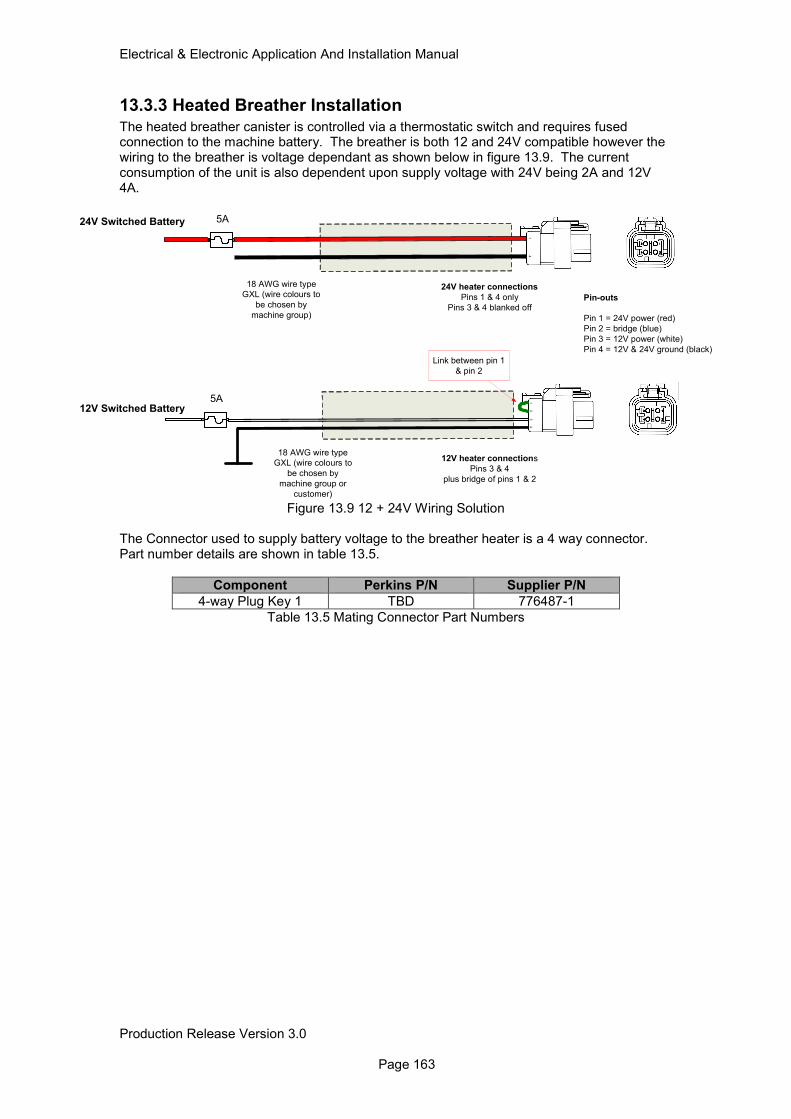
Electrical & Electronic Application And Installation Manual
Production Release Version 3.0 Page 163
13.3.3 Heated Breather Installation
The heated breather canister is controlled via a thermostatic switch and requires fused connection to the machine battery. The breather is both 12 and 24V compatible however the wiring to the breather is voltage dependant as shown below in figure 13.9. The current consumption of the unit is also dependent upon supply voltage with 24V being 2A and 12V 4A.
Figure 13.9 12 + 24V Wiring Solution
The Connector used to supply battery voltage to the breather heater is a 4 way connector. Part number details are shown in table 13.5.
Component Perkins P/N Supplier P/N
4-way Plug Key 1 TBD 776487-1
Table 13.5 Mating Connector Part Numbers
18 AWG wire type
GXL (wire colours to
be chosen by
machine group)
12V Switched Battery
Pin-outs
Pin 1 = 24V power (red)
Pin 2 = bridge (blue)
Pin 3 = 12V power (white)
Pin 4 = 12V & 24V ground (black)
18 AWG wire type
GXL (wire colours to
be chosen by
machine group or
customer)
24V Switched Battery
14
12
34
Link between pin 1
& pin 2
24V heater connections
Pins 1 & 4 only
Pins 3 & 4 blanked off
12V heater connections
Pins 3 & 4
plus bridge of pins 1 & 2
5A
5A
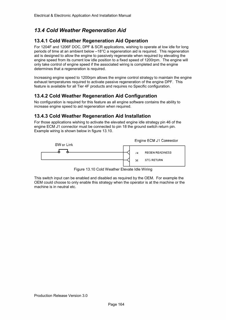
Electrical & Electronic Application And Installation Manual
Production Release Version 3.0 Page 164
13.4 Cold Weather Regeneration Aid
13.4.1 Cold Weather Regeneration Aid Operation
For 1204F and 1206F DOC, DPF & SCR applications, wishing to operate at low idle for long periods of time at an ambient below –18°C a regeneration aid is required. This regeneration aid is designed to allow the engine to passively regenerate when required by elevating the engine speed from its current low idle position to a fixed speed of 1200rpm. The engine will only take control of engine speed if the associated wiring is completed and the engine determines that a regeneration is required. Increasing engine speed to 1200rpm allows the engine control strategy to maintain the engine exhaust temperatures required to activate passive regeneration of the engine DPF. This feature is available for all Tier 4F products and requires no Specific configuration.
13.4.2 Cold Weather Regeneration Aid Configuration
No configuration is required for this feature as all engine software contains the ability to increase engine speed to aid regeneration when required.
13.4.3 Cold Weather Regeneration Aid Installation
For those applications wishing to activate the elevated engine idle strategy pin 46 of the engine ECM J1 connector must be connected to pin 18 the ground switch return pin. Example wiring is shown below in figure 13.10.
Figure 13.10 Cold Weather Elevate Idle Wiring
This switch input can be enabled and disabled as required by the OEM. For example the OEM could choose to only enable this strategy when the operator is at the machine or the machine is in neutral etc.
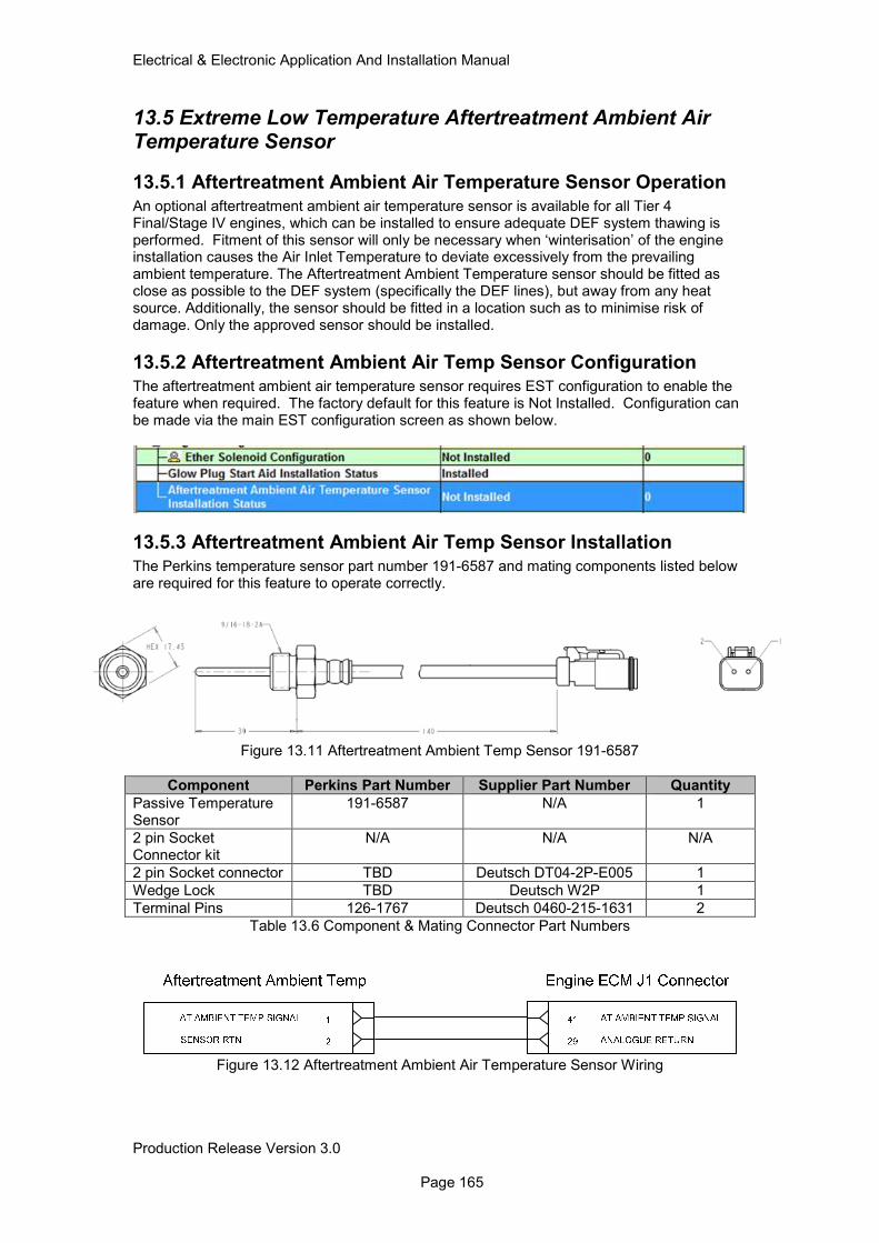
Electrical & Electronic Application And Installation Manual
Production Release Version 3.0 Page 165
13.5 Extreme Low Temperature Aftertreatment Ambient Air Temperature Sensor
13.5.1 Aftertreatment Ambient Air Temperature Sensor Operation
An optional aftertreatment ambient air temperature sensor is available for all Tier 4 Final/Stage IV engines, which can be installed to ensure adequate DEF system thawing is performed. Fitment of this sensor will only be necessary when ‘winterisation’ of the engine installation causes the Air Inlet Temperature to deviate excessively from the prevailing ambient temperature. The Aftertreatment Ambient Temperature sensor should be fitted as close as possible to the DEF system (specifically the DEF lines), but away from any heat source. Additionally, the sensor should be fitted in a location such as to minimise risk of damage. Only the approved sensor should be installed.
13.5.2 Aftertreatment Ambient Air Temp Sensor Configuration
The aftertreatment ambient air temperature sensor requires EST configuration to enable the feature when required. The factory default for this feature is Not Installed. Configuration can be made via the main EST configuration screen as shown below.
13.5.3 Aftertreatment Ambient Air Temp Sensor Installation
The Perkins temperature sensor part number 191-6587 and mating components listed below are required for this feature to operate correctly.
Figure 13.11 Aftertreatment Ambient Temp Sensor 191-6587
Component Perkins Part Number Supplier Part Number Quantity
Passive Temperature Sensor
191-6587 N/A 1
2 pin Socket Connector kit
N/A N/A N/A
2 pin Socket connector TBD Deutsch DT04-2P-E005 1
Wedge Lock TBD Deutsch W2P 1
Terminal Pins 126-1767 Deutsch 0460-215-1631 2
Table 13.6 Component & Mating Connector Part Numbers
Figure 13.12 Aftertreatment Ambient Air Temperature Sensor Wiring
Electrical & Electronic Application And Installation Manual
Production Release Version 3.0 Page 166
13.6 Engine Soft Start Protection
13.6.1 Engine Soft Start Protection Operation
After starting, a soft start strategy is employed which holds the engine speed at low idle or 850rpm depending on which is lowest for a duration between 1 and 25 seconds to allow engine systems to stabilise. Under normal system conditions, the trigger to exit the soft start strategy is oil pressure. The time taken to build oil pressure depends on many factors, for example
• Ambient temperature
• Oil temperature
• Oil grade
• Oil filter position
• Time since engine last run
• Engine starting performance Following the exit of the soft start strategy, the engine will ramp to the desired engine speed. The soft start strategy includes a maximum allowed hold time, as backup in the event of a system failure, for example, oil pressure sensor failure. Soft start mode will be exited at the expiry of this maximum hold time, irrespective of whether oil pressure has been detected. In this case, normal engine diagnostics will apply. The maximum hold time is dependent on temperature, and is in the range 5 to 25 seconds.
13.6.2 Engine Soft Start Protection Configuration There is no specific user configuration required for this feature.
13.6.3 Engine Soft Start Protection Installation
The engine ECM provides two methods for communicating the status of the soft start feature to the machine operator.
Option 1 Engine Wait to Start Lamp flash
The engine ECM will flash the Wait to start lamp output driver at a frequency of 2Hz for the duration of the soft start condition. Once conditions have been met for the exit of the soft start feature to occur the wait to start driver will turn off.
Option 2 J1939 Engine Oil Priming State (SPN 3551) The engine ECM will communicate the status of the soft start feature via the J1939 datalink PGN FE6A (65130) SPN Engine Oil Priming State 3551. More details on the format of this message can be found in section 19.3.31 of this document. The Engine Oil Priming State will operate as follows;
• During Soft start SPN 3551 will be transmitted with a 00 status (Not sufficiently Lubricated).
• Post Soft start SPN 3551 will be transmitted with 01 status (Sufficiently Lubricated).
Electrical & Electronic Application And Installation Manual
Production Release Version 3.0 Page 167
14.0 Operator Indicators & Fault Displays
14.1 Engine & AT Diagnostic Systems Both the engine and aftertreatment systems are fitted with a number of sensors and actuators designed to provide tight control over engine performance and emissions management. Each of these devices also enable the engine management system to closely monitor the health of the system and react as necessary when fault conditions occur. In the event of an electronic component failure or an out of normal control boundaries condition being raised the engine management system will react by raising a specific indicator, fault code and in some cases take protective action such as derate or shutdown. The conditions under which the engine signals a system error can be defined as fitting into one of three categories. The error category will dictate the specific engine response and the type of indication provided to the operator. The specific fault conditions are shown below. Diagnostics – These conditions are related to specific electrical hardware faults or failures such as open / short circuit conditions on sensors or wiring loom. Event Codes – Events are raised when the engine control system recognises that the current system conditions are outside of some pre-defined boundaries. Examples are coolant temperature, oil pressure and DOC intake temperature etc. Emissions System Inducements – These conditions are governed by specific emissions legislation, which requires the engine manufacturer to clearly identify specific emissions system failures to the operator outside of the normal engine fault condition strategies. A complete list of the available lamps for each Perkins Tier4F engine is shown below. Mandatory indicators are highlighted where applicable.
Indicator Product
Mandatory 1204F 1206F
Engine Warning Indicator
Yes
Engine shutdown Indicator
Yes
Engine Wait To Start Indicator
Yes
Engine oil Pressure Indicator
No
Low DEF Indicator Yes
Emissions System Failure Indicator
Yes
Wait To Disconnect Indicator
Yes
DES Active Indicator
x Yes if DES is enabled
Table 14.1 Mandatory Indicator Requirements
14.1.1 Monitoring System Fault Status Levels All engine and aftertreatment fault indicators are assigned a warning category indicator (WCI), which indicates the severity of the specific diagnostic, event or emissions critical failure. The high level operation of the indicator control strategy is shown below in figure 14.1. It should be noted that the protect indicator status is only available via J1939 and not as a hardwired ECM output. If hardwired engine warning and shutdown lamps are used then engine events will be displayed in the same manner as engine diagnostic code, via a warning lamp and shutdown lamp only.
Electrical & Electronic Application And Installation Manual
Production Release Version 3.0 Page 168
Figure 14.1 General Indicator Operation
14.2 Gauge Drivers If a needle type analogue gauge is required to display an engine parameter such as engine speed, oil pressure, or coolant temperature, it is recommended that the OEM use a gauge or display that can use the parameters broadcast by the ECM on the J1939 datalink. As an alternative, traditional single wire gauge ‘senders’ may be used if a suitable tapping is available. If this implementation is required, please contact the Electronic Applications team to discuss requirements. A traditional tacho signal may be obtained from the ‘W’ terminal of the alternator, although this will not be as accurate as the value transmitted on the J1939 datalink.
Electrical & Electronic Application And Installation Manual
Production Release Version 3.0 Page 169
14.2.1 Datalink Driven Intelligent Displays
J1939 enabled operator display / gauge units can be connected to the engine J1939 datalink. Perkins offers lamp information, which conforms, to the J1939 standard PGN and SPN messaging system. For more information on the J1939 messages supported via the ECM J1939 data bus please refer to section 18 of this document. Devices that are connected to the J1939 datalink should meet the following standard if the OEM does not intend fitting the indicator lamps.
14.2.2 Minimum Functional Specification for J1939 display.
The following points describe the functional specification for the installation of an operator display.
• The display is always on when the engine is running.
• The display should be in the line-of-sight of the machine operator during machine operation.
• Display of the whole J1939 fault code including Suspect Parameter Number (SPN), Failure Mode Indicator (FMI) and occurrence number.
• Clear indication of what action, if any the operator is required to take.
• Display of engine speed.
• Audible or bright lamp warning when a new fault code is detected.
• The scaling of any gauges (e.g. coolant temperature) should be such that the needle is not far to the right of vertical when the engine is in normal operation (this would give the impression that the engine was abnormally hot, when in fact it is running within its design limits).
Perkins will under no circumstances change the engine J1939 implementation in order to resolve compatibility issues with gauges or displays other than those supplied directly by Perkins. Gauge manufacturers may contact the electronic applications team however, for information and assistance in ensuring that their products are compatible with the engine ECM. To support new standards and requirements, Perkins may add to the fault code table. Therefore, any active engine fault codes including those not recognized or referenced should be displayed.
14.3 Lamp Outputs & Operation
14.3.1 Hardwired Lamp Outputs
All mandatory engine and aftertreatment indicators are provided as standard as dedicated ECM outputs. Engine ECM pin allocation for each of these indicators is shown below in table 14.2
Indicator Description Mandatory Fit Engine
Family Pin Allocations ECM J1
Warning Indicator All 31
Shutdown Indicator All 32
Engine Wait To Start Indicator
All 16
Oil Pressure Indicator Optional 23
Emissions System Malfunction Indicator
All 40
Low DEF Level Indicator All 39
Wait To Disconnect Indicator Recommended All 24
Delayed Engine Shutdown Active
Optional 1206F 48
Table 14.2 Hardwired Indicator ECM Location
Electrical & Electronic Application And Installation Manual
Production Release Version 3.0 Page 170
14.3.2 J1939 Indicator Support
All hardwired status indicators are supported as J1939 messages to support those customers wishing to incorporate these signals into a machine display. PGN and SPN support for these parameters are shown below.
Indicator Description PGN SPN
Warning Indicator FECA (65226) 624
Warning Indicator Flash FECA (65226) 3040
Shutdown Indicator FECA (65226) 623
Engine Protect Indicator FECA (65226) 987
Engine Protect Indicator Flash
FECA (65226) 3041
Engine Wait To Start Indicator
FEE4 (65252) 1081
Oil Pressure Indicator N/A N/A
Emissions System Malfunction Indicator
FECA (65226) 1213
Emissions System Malfunction Indicator Flash
FECA (65226) 3038
Low DEF Level Indicator (65110) (5245)
Wait To Disconnect Indicator F023 (61475) 4332
Delayed Engine Shutdown Active
FD92 (64914) 3543
Table 14.3 J1939 Indicator Support
Electrical & Electronic Application And Installation Manual
Production Release Version 3.0 Page 171
14.3.3 Indicator ISO Reference Symbols
Symbol Symbol Title (ISO)
Symbol Title Description ISO Ref
Engine Failure Engine Malfunction
Engine Warning Indicator
Used to indicate engine and emissions system diagnostics
ISO 7000-1371
Engine Stop Shutdown Indicator
Indicates engine shutdown required for severe system faults / events
ISO 7000-1388
Engine Electrical Preheat
Engine Wait To Start Indicator
Indicates pre-heat phase has been completed
ISO 7000-1704
Engine Lubricating Oil Pressure
Oil Pressure Indicator
Indicates low oil pressure
ISO 7000-1374
Emissions System Malfunction Indicator
Emissions System Malfunction Indicator
Indicates a failure of an emissions critical component
ISO 7000-2596
Low DEF Level Indicator
Low DEF Level Indicator
Used to indicate low DEF fluid level
ISO 7000-2946
Delayed Engine Shutdown Active*
Delayed Engine Shutdown Active
Only required for 1206F engines that have DES enabled.
ISO 7000-2303
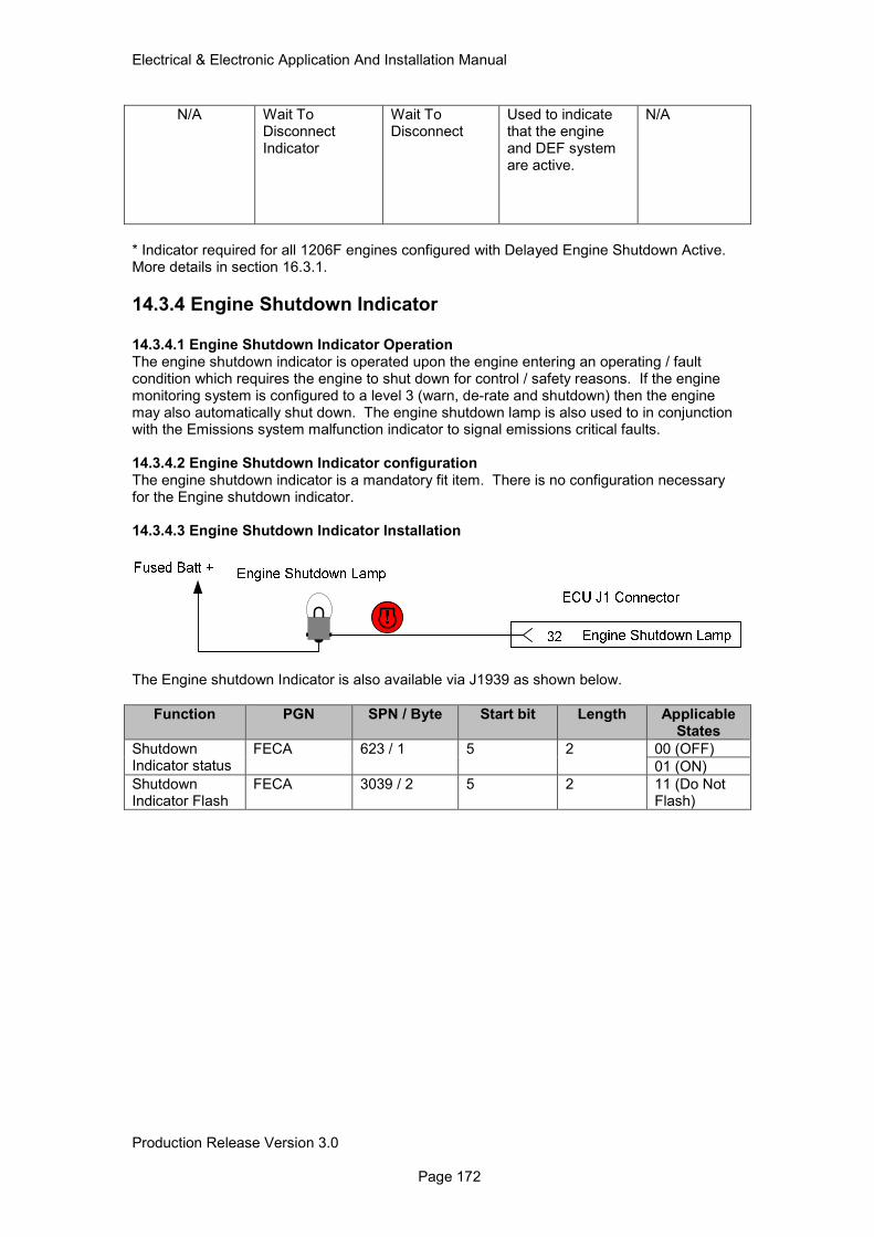
Electrical & Electronic Application And Installation Manual
Production Release Version 3.0 Page 172
N/A Wait To Disconnect Indicator
Wait To Disconnect
Used to indicate that the engine and DEF system are active.
N/A
* Indicator required for all 1206F engines configured with Delayed Engine Shutdown Active. More details in section 16.3.1.
14.3.4 Engine Shutdown Indicator
14.3.4.1 Engine Shutdown Indicator Operation The engine shutdown indicator is operated upon the engine entering an operating / fault condition which requires the engine to shut down for control / safety reasons. If the engine monitoring system is configured to a level 3 (warn, de-rate and shutdown) then the engine may also automatically shut down. The engine shutdown lamp is also used to in conjunction with the Emissions system malfunction indicator to signal emissions critical faults. 14.3.4.2 Engine Shutdown Indicator configuration The engine shutdown indicator is a mandatory fit item. There is no configuration necessary for the Engine shutdown indicator. 14.3.4.3 Engine Shutdown Indicator Installation
The Engine shutdown Indicator is also available via J1939 as shown below.
Function PGN SPN / Byte Start bit Length Applicable States
Shutdown Indicator status
FECA 623 / 1 5 2 00 (OFF)
01 (ON)
Shutdown Indicator Flash
FECA 3039 / 2 5 2 11 (Do Not Flash)
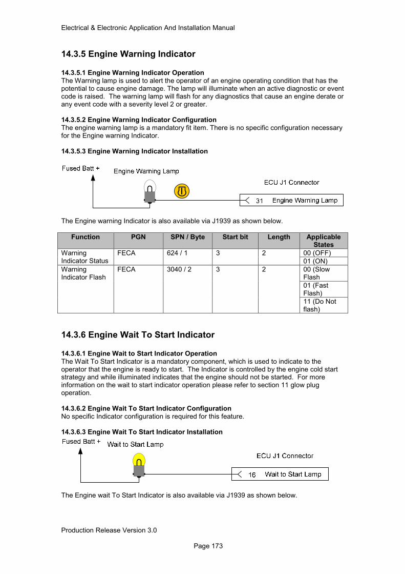
Electrical & Electronic Application And Installation Manual
Production Release Version 3.0 Page 173
14.3.5 Engine Warning Indicator
14.3.5.1 Engine Warning Indicator Operation The Warning lamp is used to alert the operator of an engine operating condition that has the potential to cause engine damage. The lamp will illuminate when an active diagnostic or event code is raised. The warning lamp will flash for any diagnostics that cause an engine derate or any event code with a severity level 2 or greater. 14.3.5.2 Engine Warning Indicator Configuration The engine warning lamp is a mandatory fit item. There is no specific configuration necessary for the Engine warning Indicator. 14.3.5.3 Engine Warning Indicator Installation
The Engine warning Indicator is also available via J1939 as shown below.
Function PGN SPN / Byte Start bit Length Applicable States
Warning Indicator Status
FECA 624 / 1 3 2 00 (OFF)
01 (ON)
Warning Indicator Flash
FECA 3040 / 2 3 2 00 (Slow Flash
01 (Fast Flash)
11 (Do Not flash)
14.3.6 Engine Wait To Start Indicator 14.3.6.1 Engine Wait to Start Indicator Operation The Wait To Start Indicator is a mandatory component, which is used to indicate to the operator that the engine is ready to start. The Indicator is controlled by the engine cold start strategy and while illuminated indicates that the engine should not be started. For more information on the wait to start indicator operation please refer to section 11 glow plug operation. 14.3.6.2 Engine Wait To Start Indicator Configuration No specific Indicator configuration is required for this feature. 14.3.6.3 Engine Wait To Start Indicator Installation
The Engine wait To Start Indicator is also available via J1939 as shown below.
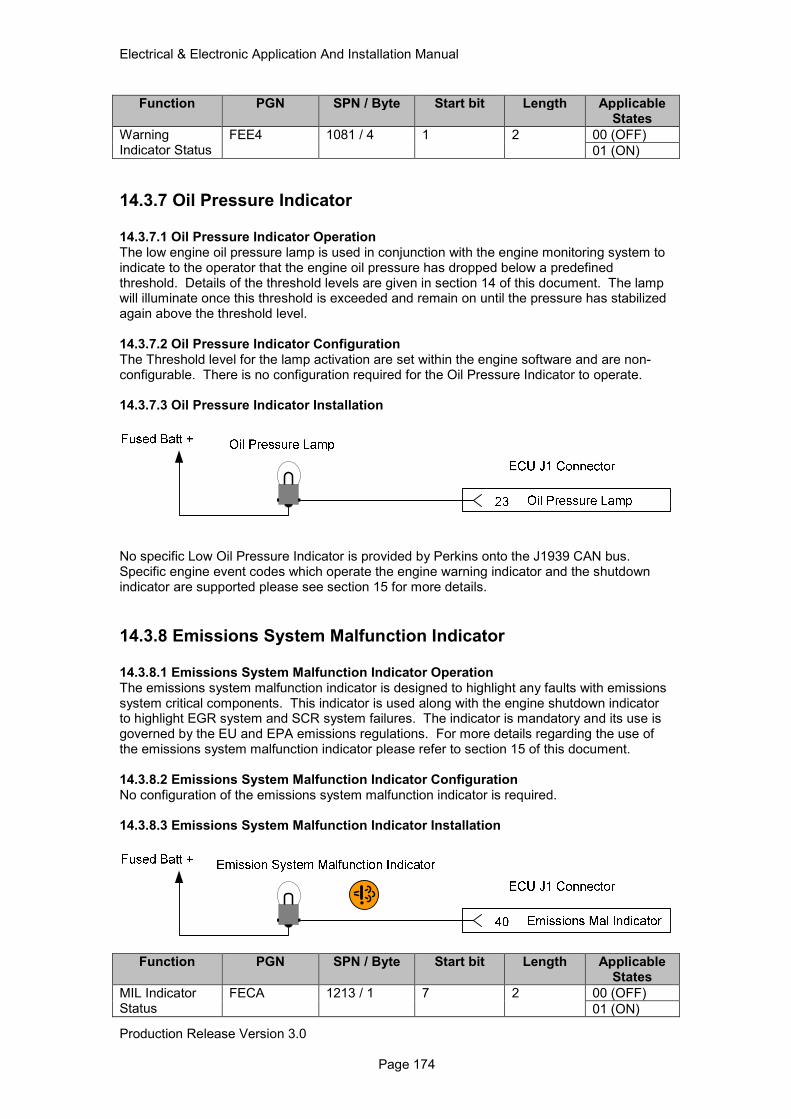
Electrical & Electronic Application And Installation Manual
Production Release Version 3.0 Page 174
Function PGN SPN / Byte Start bit Length Applicable States
Warning Indicator Status
FEE4 1081 / 4 1 2 00 (OFF)
01 (ON)
14.3.7 Oil Pressure Indicator 14.3.7.1 Oil Pressure Indicator Operation The low engine oil pressure lamp is used in conjunction with the engine monitoring system to indicate to the operator that the engine oil pressure has dropped below a predefined threshold. Details of the threshold levels are given in section 14 of this document. The lamp will illuminate once this threshold is exceeded and remain on until the pressure has stabilized again above the threshold level. 14.3.7.2 Oil Pressure Indicator Configuration The Threshold level for the lamp activation are set within the engine software and are non-configurable. There is no configuration required for the Oil Pressure Indicator to operate. 14.3.7.3 Oil Pressure Indicator Installation
No specific Low Oil Pressure Indicator is provided by Perkins onto the J1939 CAN bus. Specific engine event codes which operate the engine warning indicator and the shutdown indicator are supported please see section 15 for more details.
14.3.8 Emissions System Malfunction Indicator 14.3.8.1 Emissions System Malfunction Indicator Operation The emissions system malfunction indicator is designed to highlight any faults with emissions system critical components. This indicator is used along with the engine shutdown indicator to highlight EGR system and SCR system failures. The indicator is mandatory and its use is governed by the EU and EPA emissions regulations. For more details regarding the use of the emissions system malfunction indicator please refer to section 15 of this document. 14.3.8.2 Emissions System Malfunction Indicator Configuration No configuration of the emissions system malfunction indicator is required. 14.3.8.3 Emissions System Malfunction Indicator Installation
Function PGN SPN / Byte Start bit Length Applicable States
MIL Indicator Status
FECA 1213 / 1 7 2 00 (OFF)
01 (ON)
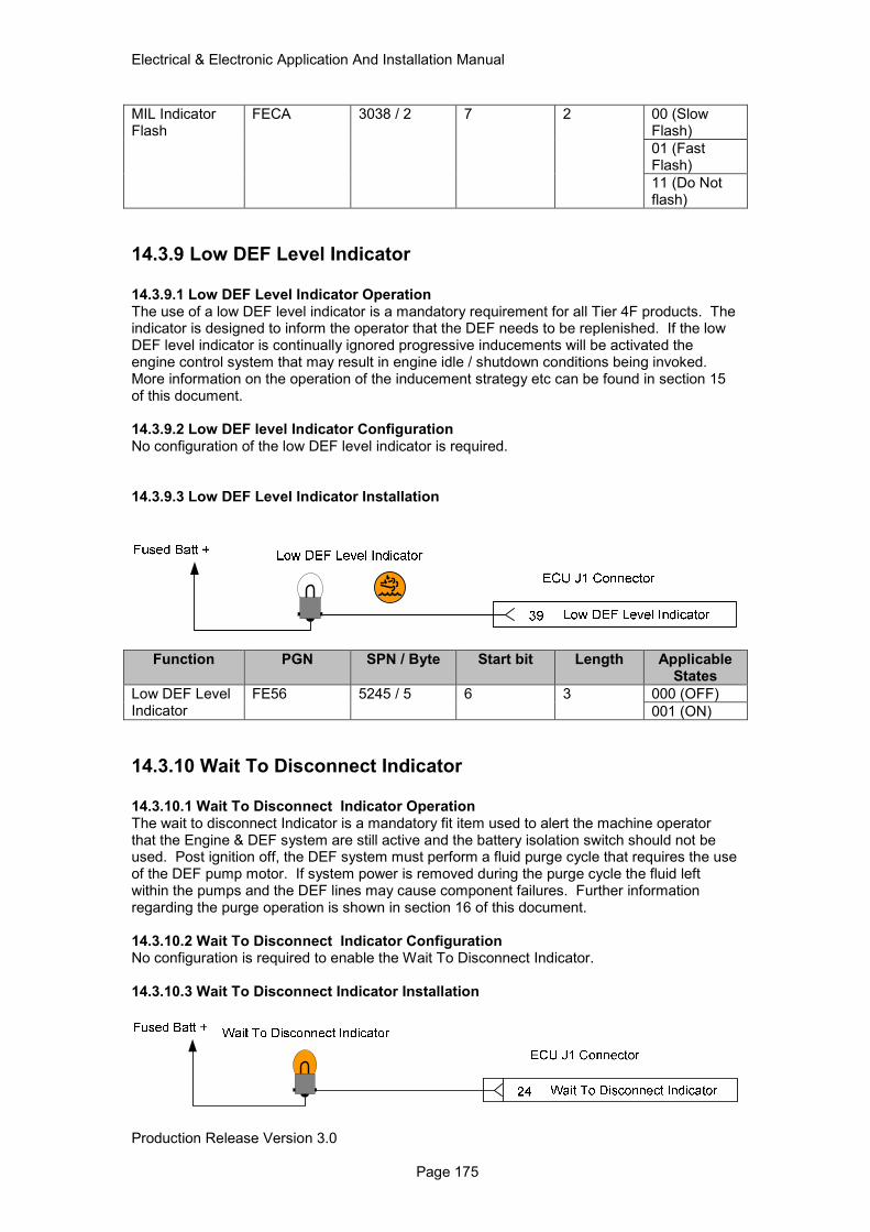
Electrical & Electronic Application And Installation Manual
Production Release Version 3.0 Page 175
MIL Indicator Flash
FECA 3038 / 2 7 2 00 (Slow Flash)
01 (Fast Flash)
11 (Do Not flash)
14.3.9 Low DEF Level Indicator
14.3.9.1 Low DEF Level Indicator Operation The use of a low DEF level indicator is a mandatory requirement for all Tier 4F products. The indicator is designed to inform the operator that the DEF needs to be replenished. If the low DEF level indicator is continually ignored progressive inducements will be activated the engine control system that may result in engine idle / shutdown conditions being invoked. More information on the operation of the inducement strategy etc can be found in section 15 of this document. 14.3.9.2 Low DEF level Indicator Configuration No configuration of the low DEF level indicator is required. 14.3.9.3 Low DEF Level Indicator Installation
Function PGN SPN / Byte Start bit Length Applicable States
Low DEF Level Indicator
FE56 5245 / 5 6 3 000 (OFF)
001 (ON)
14.3.10 Wait To Disconnect Indicator 14.3.10.1 Wait To Disconnect Indicator Operation The wait to disconnect Indicator is a mandatory fit item used to alert the machine operator that the Engine & DEF system are still active and the battery isolation switch should not be used. Post ignition off, the DEF system must perform a fluid purge cycle that requires the use of the DEF pump motor. If system power is removed during the purge cycle the fluid left within the pumps and the DEF lines may cause component failures. Further information regarding the purge operation is shown in section 16 of this document. 14.3.10.2 Wait To Disconnect Indicator Configuration No configuration is required to enable the Wait To Disconnect Indicator. 14.3.10.3 Wait To Disconnect Indicator Installation
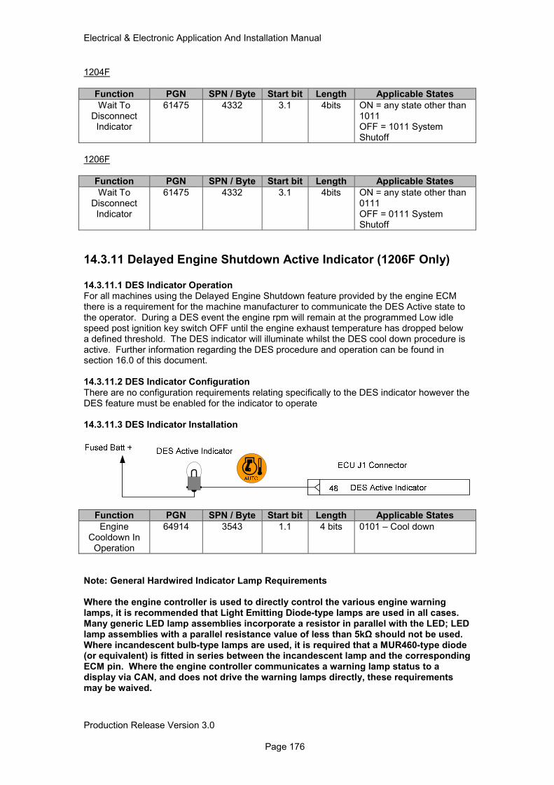
Electrical & Electronic Application And Installation Manual
Production Release Version 3.0 Page 176
1204F
Function PGN SPN / Byte Start bit Length Applicable States
Wait To Disconnect Indicator
61475 4332 3.1 4bits ON = any state other than 1011 OFF = 1011 System Shutoff
1206F
Function PGN SPN / Byte Start bit Length Applicable States
Wait To Disconnect Indicator
61475 4332 3.1 4bits ON = any state other than 0111 OFF = 0111 System Shutoff
14.3.11 Delayed Engine Shutdown Active Indicator (1206F Only)
14.3.11.1 DES Indicator Operation For all machines using the Delayed Engine Shutdown feature provided by the engine ECM there is a requirement for the machine manufacturer to communicate the DES Active state to the operator. During a DES event the engine rpm will remain at the programmed Low idle speed post ignition key switch OFF until the engine exhaust temperature has dropped below a defined threshold. The DES indicator will illuminate whilst the DES cool down procedure is active. Further information regarding the DES procedure and operation can be found in section 16.0 of this document. 14.3.11.2 DES Indicator Configuration There are no configuration requirements relating specifically to the DES indicator however the DES feature must be enabled for the indicator to operate 14.3.11.3 DES Indicator Installation
Function PGN SPN / Byte Start bit Length Applicable States
Engine Cooldown In
Operation
64914 3543 1.1 4 bits 0101 – Cool down
Note: General Hardwired Indicator Lamp Requirements Where the engine controller is used to directly control the various engine warning lamps, it is recommended that Light Emitting Diode-type lamps are used in all cases. Many generic LED lamp assemblies incorporate a resistor in parallel with the LED; LED lamp assemblies with a parallel resistance value of less than 5kΩ should not be used. Where incandescent bulb-type lamps are used, it is required that a MUR460-type diode (or equivalent) is fitted in series between the incandescent lamp and the corresponding ECM pin. Where the engine controller communicates a warning lamp status to a display via CAN, and does not drive the warning lamps directly, these requirements may be waived.
Electrical & Electronic Application And Installation Manual
Production Release Version 3.0 Page 177
15.0 Engine & Aftertreatment Monitoring System The engine control system is designed to monitor each engine and aftertreatment sensor / actuator and react to system critical or emissions critical failures. When a system error occurs such as high engine coolant temperature the engine monitoring system reacts by raising the appropriate engine diagnostic level and in some cases forces the engine into a derate condition or controlled shutdown. It is recognized that for some applications a control system induced engine shutdown or derate could cause safety concerns or auxiliary equipment damage and for these reasons the engine response can be configured. It should be noted however that Tier4 Final legislation mandates the use of some specific system controls and failure reactions in the form of derates etc which cannot be disabled or adjusted. The following sections provide details of these exceptions and how they operate.
15.1 General Information The engine monitoring system includes two parts. The first part can be configured via the Monitoring Mode screen in the service tool and shows the individual parameters being monitored, the levels of severity that can be activated and the trip points at which these warnings will activate. In some cases these parameters can be changed by the user. The second part is configured through the main configuration screen and is where the engines response to the severity level can be set. If a level 2 (moderate severity) becomes active then a derate of the engines power can be enabled. If a level 3 warning (most severe) becomes active then an engine shut down can be enabled. In both cases these configurations can be disabled so regardless of warning level the engine will continue to operate until it is unable to do so. Note: Due to changes in emissions legislation some emissions critical diagnostics have fixed engine-response criteria, which is non-configurable. These conditions are shown in section 15.3.
15.1.1 Monitoring Levels There are three configurable Engine Monitoring options available within the engine software. These options determine the engines response to the activation of a parameters severity level. The three available options are;
• Warn (Always active)
• Derate
• Shutdown Engine warning is always active and cannot be disabled. The derate and shutdown parameters can however be enabled or disabled using the service tool as shown below in table 15.1. Monitoring Mode - EST Configurable Parameters
Monitoring Mode (listed under Miscellaneous in EST)
ET Description Range or Option Description
Monitoring Mode Shutdowns Disabled/Enabled Switches on or off the shutdown feature
Monitoring Mode Derates Enabled/Enabled Switches on/off the derate feature
Table 15.1 Monitoring Mode Configuration 15.1.1.1 Warning The Engine Monitoring warning is always active and cannot be disabled. Activation of this Engine monitoring option ensures that upon the engine measuring an engine parameter

Electrical & Electronic Application And Installation Manual
Production Release Version 3.0 Page 178
above the configurable threshold level a warning is triggered (Event Code), which is logged by the engine ECM and the appropriate lamp driver is activated. 15.1.1.2 De-rate Each monitored parameter that uses the derate function has its own derate trigger threshold and map. If the derate threshold is equaled or exceeded by any parameter, a derate protection will be set active and the engine will derate. The ECM will log these events and turn on the appropriate lamp driver. The level of engine % derate will vary depending upon the parameter being monitored. A derate is only initialized when a severity level 2 is raised. 15.1.1.3 Shutdown The engine shutdown indication lamp driver will be triggered when any parameter equals or exceeds its shutdown threshold for a time exceeding its shutdown indication guard time. Physical engine shutdown will occur only if enabled by the configurable parameter. The ECM will log these events and turn on the appropriate lamp driver. A Shutdown function will only operate once a severity level 3 is raised.
15.1.2 Parameter Severity Levels
The monitoring system provides up to three possible severity levels for each of the configurable system parameters. These levels are defined as severity level 1 (least server), 2 (moderate severity) and 3 (most server). The level of severity is displayed upon activation of the parameter Event code for example. Engine coolant temperature severity level 1 is exceeded. Upon activation an Event code is generated in this case E361-1. The –1 part of the code signals that a severity level 1 threshold has been exceeded. If a level 2 is raised then the same event code is raised but with a –2. The levels available for each parameter are set within software and cannot be changed. Whilst the number of levels are not configurable each available level is designed to offer an increased level of action by the engine once a threshold for the monitored parameter has been set. Some engine parameters enable the customer to directly configure the thresholds at which these conditions are activated and others are fixed. The table below details the Monitoring system parameters that are available for configuration by the customer. The table is split into two sections, the first showing those parameters which offer both a threshold configuration and an engine action configuration, and those which offer an engine action configuration only.
Monitoring System Parameters
Configurable Threshold
Severity Level
Level 1 Level 2 Level 3
Engine Coolant Temperature Yes Yes Yes Yes
Engine Over speed Yes Yes No Yes
Intake Manifold Air Temperature
Yes Yes Yes No
High EGR Temperature Yes Yes Yes Yes
Parameters which have Fixed Factory Set Thresholds
Oil Pressure No Yes No Yes
Table 15.2 Available Engine Monitoring System Parameters
It should be noted that when engine shutdowns are enabled the following system response is true.
• Severity Level 1 (least severe) = Engine warning
• Severity Level 2 (moderate severity) = Engine Derate
• Severity Level 3 (most severe) = Engine Shutdown
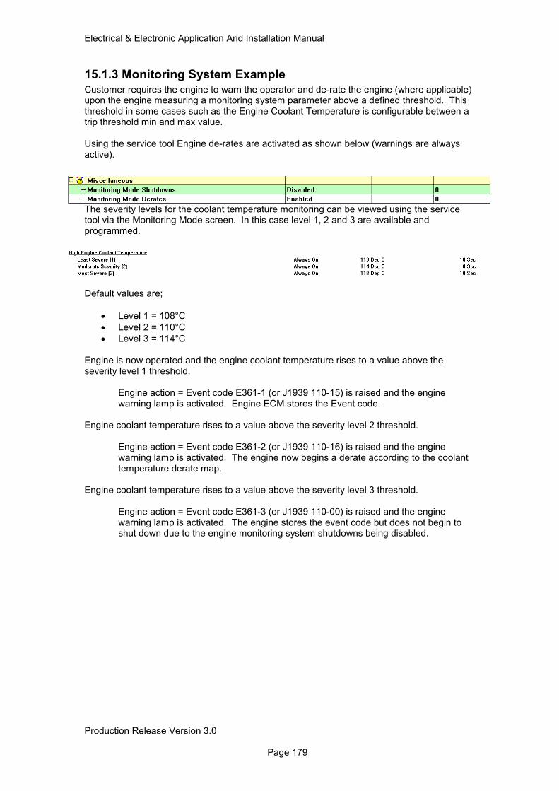
Electrical & Electronic Application And Installation Manual
Production Release Version 3.0 Page 179
15.1.3 Monitoring System Example
Customer requires the engine to warn the operator and de-rate the engine (where applicable) upon the engine measuring a monitoring system parameter above a defined threshold. This threshold in some cases such as the Engine Coolant Temperature is configurable between a trip threshold min and max value. Using the service tool Engine de-rates are activated as shown below (warnings are always active).
The severity levels for the coolant temperature monitoring can be viewed using the service tool via the Monitoring Mode screen. In this case level 1, 2 and 3 are available and programmed.
Default values are;
• Level 1 = 108°C
• Level 2 = 110°C
• Level 3 = 114°C Engine is now operated and the engine coolant temperature rises to a value above the severity level 1 threshold.
Engine action = Event code E361-1 (or J1939 110-15) is raised and the engine warning lamp is activated. Engine ECM stores the Event code.
Engine coolant temperature rises to a value above the severity level 2 threshold.
Engine action = Event code E361-2 (or J1939 110-16) is raised and the engine warning lamp is activated. The engine now begins a derate according to the coolant temperature derate map.
Engine coolant temperature rises to a value above the severity level 3 threshold.
Engine action = Event code E361-3 (or J1939 110-00) is raised and the engine warning lamp is activated. The engine stores the event code but does not begin to shut down due to the engine monitoring system shutdowns being disabled.
Electrical & Electronic Application And Installation Manual
Production Release Version 3.0 Page 180
15.2 Non Emissions Critical component Monitoring & Protection All of the components / parameters shown here offer some level of configurability and / or are effected by the configuration of the engine monitoring system levels i.e. warn, derate and shutdown.
15.2.1 Coolant Temperature 15.2.1.1 Coolant Temperature Monitoring Mode Operation The high engine coolant temperature monitoring mode is configured to indicate to the operator that the engine coolant temperature has exceed a pre-determined threshold. The configuration of these thresholds can be adjusted by the user to determine when a Severity Level 1, 2 and 3 is activated. The table below shows the default configuration for this mode.
Parameter Temp °C De-rate %
Severity L1 109 0
Severity L2 111 25
112 50
113 75
Severity L3 114 100
115 100
116 100
Table 15.3 Coolant Temperature Monitoring Mode Derate Operation Once the engine ECM detects that the engine coolant temperature has exceeded one or more of the defined threshold limits a corresponding event code is raised as shown below.
Service Tool
Description
J1939 Description
Status SPN (J1939)
FMI (J1939)
Event Code
Engine Action (If Enabled)
High Engine Coolant
Temperature
Engine Coolant
Temperature
Severity L1 110 15 E361-1 Warning Lamp Only
Severity L2 110 16 E361-2 Engine % Derate
Severity L3 110 00 E361-3 Engine Shutdown
Table 15.4 Coolant Temperature Monitoring 15.2.1.2 Coolant Temperature Monitoring Mode Configuration The high engine coolant temperature threshold settings are available for adjustment within Perkins EST for all monitoring system severity levels. There are however upper and lower limits outside of which the thresholds cannot be set these are shown below
Monitoring Mode Level
Trip Threshold Min Trip Threshold Max
Severity L1 85°C 109°C
Severity L2 86°C 111°C
Severity L3 87°C 114°C
Table 15.5 Coolant Temperature Monitoring Mode Configuration 15.2.1.3 Coolant Temperature Monitoring Mode Installation No installation is required for the engine coolant temperature monitoring function.
15.2.2 Engine Oil Pressure 15.2.2.1 Engine Oil Pressure Monitoring Mode Operation Engine oil pressure is automatically monitored by the engine ECM to protect the engine from operating without sufficient oil pressure, as low oil pressure could lead to catastrophic engine
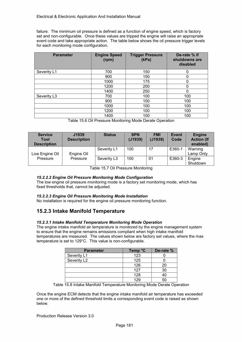
Electrical & Electronic Application And Installation Manual
Production Release Version 3.0 Page 181
failure. The minimum oil pressure is defined as a function of engine speed, which is factory set and non-configurable. Once these values are tripped the engine will raise an appropriate event code and take appropriate action. The table below shows the oil pressure trigger levels for each monitoring mode configuration.
Parameter Engine Speed (rpm)
Trigger Pressure (kPa)
De-rate % if shutdowns are
disabled
Severity L1 700 150 0
900 150 0
1000 175 0
1200 200 0
1400 250 0
Severity L3 700 100 100
900 100 100
1000 100 100
1200 100 100
1400 100 100
Table 15.6 Oil Pressure Monitoring Mode Derate Operation
Service Tool
Description
J1939 Description
Status SPN (J1939)
FMI (J1939)
Event Code
Engine Action (If enabled)
Low Engine Oil Pressure
Engine Oil Pressure
Severity L1 100 17 E360-1 Warning Lamp Only
Severity L3 100 01 E360-3 Engine Shutdown
Table 15.7 Oil Pressure Monitoring 15.2.2.2 Engine Oil Pressure Monitoring Mode Configuration The low engine oil pressure monitoring mode is a factory set monitoring mode, which has fixed thresholds that, cannot be adjusted. 15.2.2.3 Engine Oil Pressure Monitoring Mode Installation No installation is required for the engine oil pressure monitoring function.
15.2.3 Intake Manifold Temperature
15.2.3.1 Intake Manifold Temperature Monitoring Mode Operation The engine intake manifold air temperature is monitored by the engine management system to ensure that the engine remains emissions compliant when high intake manifold temperatures are measured. The values shown below are factory set values, where the max temperature is set to 129°C. This value is non-configurable.
Parameter Temp °C De-rate %
Severity L1 123 0
Severity L2 125 0
126 20
127 30
128 40
129 50
Table 15.8 Intake Manifold Temperature Monitoring Mode Derate Operation Once the engine ECM detects that the engine intake manifold air temperature has exceeded one or more of the defined threshold limits a corresponding event code is raised as shown below.
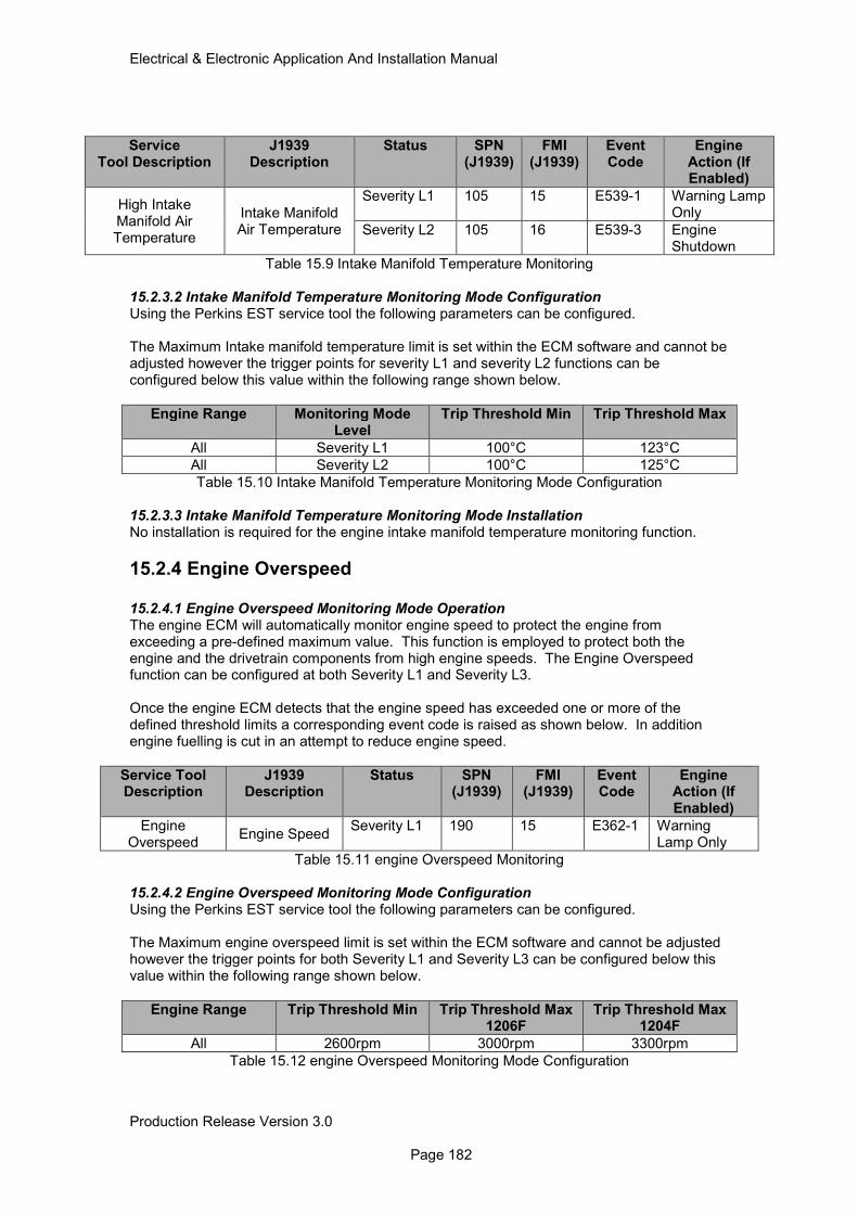
Electrical & Electronic Application And Installation Manual
Production Release Version 3.0 Page 182
Service Tool Description
J1939 Description
Status SPN (J1939)
FMI (J1939)
Event Code
Engine Action (If Enabled)
High Intake Manifold Air Temperature
Intake Manifold Air Temperature
Severity L1 105 15 E539-1 Warning Lamp Only
Severity L2 105 16 E539-3 Engine Shutdown
Table 15.9 Intake Manifold Temperature Monitoring 15.2.3.2 Intake Manifold Temperature Monitoring Mode Configuration Using the Perkins EST service tool the following parameters can be configured. The Maximum Intake manifold temperature limit is set within the ECM software and cannot be adjusted however the trigger points for severity L1 and severity L2 functions can be configured below this value within the following range shown below.
Engine Range Monitoring Mode Level
Trip Threshold Min Trip Threshold Max
All Severity L1 100°C 123°C
All Severity L2 100°C 125°C
Table 15.10 Intake Manifold Temperature Monitoring Mode Configuration 15.2.3.3 Intake Manifold Temperature Monitoring Mode Installation No installation is required for the engine intake manifold temperature monitoring function.
15.2.4 Engine Overspeed 15.2.4.1 Engine Overspeed Monitoring Mode Operation The engine ECM will automatically monitor engine speed to protect the engine from exceeding a pre-defined maximum value. This function is employed to protect both the engine and the drivetrain components from high engine speeds. The Engine Overspeed function can be configured at both Severity L1 and Severity L3. Once the engine ECM detects that the engine speed has exceeded one or more of the defined threshold limits a corresponding event code is raised as shown below. In addition engine fuelling is cut in an attempt to reduce engine speed.
Service Tool Description
J1939 Description
Status SPN (J1939)
FMI (J1939)
Event Code
Engine Action (If Enabled)
Engine Overspeed
Engine Speed Severity L1 190 15 E362-1 Warning
Lamp Only
Table 15.11 engine Overspeed Monitoring
15.2.4.2 Engine Overspeed Monitoring Mode Configuration Using the Perkins EST service tool the following parameters can be configured. The Maximum engine overspeed limit is set within the ECM software and cannot be adjusted however the trigger points for both Severity L1 and Severity L3 can be configured below this value within the following range shown below.
Engine Range Trip Threshold Min Trip Threshold Max 1206F
Trip Threshold Max 1204F
All 2600rpm 3000rpm 3300rpm
Table 15.12 engine Overspeed Monitoring Mode Configuration
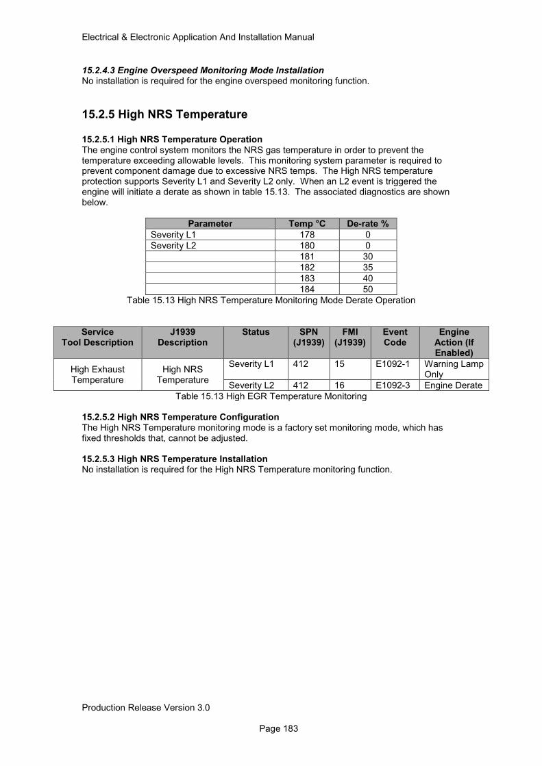
Electrical & Electronic Application And Installation Manual
Production Release Version 3.0 Page 183
15.2.4.3 Engine Overspeed Monitoring Mode Installation No installation is required for the engine overspeed monitoring function.
15.2.5 High NRS Temperature
15.2.5.1 High NRS Temperature Operation The engine control system monitors the NRS gas temperature in order to prevent the temperature exceeding allowable levels. This monitoring system parameter is required to prevent component damage due to excessive NRS temps. The High NRS temperature protection supports Severity L1 and Severity L2 only. When an L2 event is triggered the engine will initiate a derate as shown in table 15.13. The associated diagnostics are shown below.
Parameter Temp °C De-rate %
Severity L1 178 0
Severity L2 180 0
181 30
182 35
183 40
184 50
Table 15.13 High NRS Temperature Monitoring Mode Derate Operation
Service Tool Description
J1939 Description
Status SPN (J1939)
FMI (J1939)
Event Code
Engine Action (If Enabled)
High Exhaust Temperature
High NRS Temperature
Severity L1 412 15 E1092-1 Warning Lamp Only
Severity L2 412 16 E1092-3 Engine Derate
Table 15.13 High EGR Temperature Monitoring 15.2.5.2 High NRS Temperature Configuration The High NRS Temperature monitoring mode is a factory set monitoring mode, which has fixed thresholds that, cannot be adjusted. 15.2.5.3 High NRS Temperature Installation No installation is required for the High NRS Temperature monitoring function.
Electrical & Electronic Application And Installation Manual
Production Release Version 3.0 Page 184
15.3 Emissions Critical Components Monitoring & Protection Tier 4 Final /Stage IV Emissions standards stipulate that the use of operator inducements are mandatory for all SCR equipped non road engines. The term Inducement covers any actions intended to alert / prompt the operator of a machine to repair or perform maintenance on the emissions control system. Examples of inducements are use of engine warning lamps, engine torque or power derates and engine speed limiting etc.
15.3.1 Inducement Strategy High Level Overview
The 1204F to 1206F engine inducement strategy can be split into four distinct escalation sections;
• Warning indicators
• Specific Fault messages
• Engine Torque derates
• Final engine inducement strategies including forced engine idle down or shutdown. The areas of the emissions system covered by the legislation and therefore forming part of the specific Inducement strategy are;
• Low DEF Level
• Poor DEF Quality (Q)
• Dosing Interruption (D)
• System Tampering (T)
• Impeded EGR (E) Whilst the requirement for specific Inducement strategies relating to the engine emissions system are required by both the EU and EPA, the mandatory implementation requirements for each legislation do vary. For this reason Perkins has implemented a combined inducement strategy, which meets both emissions standards.
15.3.2 Combined EU/EPA Inducement Strategy Operation
The combined EU/EPA Inducement strategy can be segmented into specific responses for;
• DEF Quality, Tampering and Dosing Interruption
• Impeded EGR
• Low DEF Level In the event of one or more of these conditions becoming active the engine control system will raise an engine diagnostic or event code for the specific item or system causing the problem. In addition to this diagnostic code the engine will also raise further codes to indicate that the inducement strategy has been operated. The initial Diagnostic / event code is designed to activate the engine warning indicator as with all engine related problems. The second set of codes shown below are responsible for activation of the operator annunciation strategy shown in sections 15.3.2.1, 15.3.2.2 and 15.3.2.3. Inducement escalation codes applicable to section 15.3.2.1 & 15.3.2.2
• 5246-15 – Aftertreatment SCR Operator Inducement Severity High – Least Severe (Level 1)
• 5246-16 - Aftertreatment SCR Operator Inducement Severity High – Moderate Severity (Level 2)
• 5246-0 - Aftertreatment SCR Operator Inducement Severity High – Most Severe (Level 3)
Electrical & Electronic Application And Installation Manual
Production Release Version 3.0 Page 185
Inducement escalation codes applicable to section 15.3.2.3
• 1761-17 – Catalyst Tank Level Low – Least Severe (Level 1)
• 1761-18 – Catalyst Tank Level Low – Moderate Severity (Level 2)
• 1761-1 - Catalyst Tank Level Low – Most Severe (Level 3) 15.3.2.1 DEF Quality, Tampering & Dosing Interruption
Normal Operation
Level 1 Level 2 Level 3 Safe Harbor
Inducement Time 1st Occurrence
Until Fault 2.5hrs 70mins Until Fault Heals
20mins Initiated by first key cycle after Level 3
Inducement Time Repeat Occurrence
Until Fault 5mins 5mins Until Fault Heals 20mins Initiated by first key cycle after Level 3
Inducement None None None 5 minute Cool down with 100% Torque derate Then Shutdown or Idle Only
None
Notification None
Emissions System Failure Lamp
+
Engine Shutdown Lamp
Electrical & Electronic Application And Installation Manual
Production Release Version 3.0 Page 186
15.3.2.2 Impeded EGR
Normal Operation
Level 1 Level 2 Level 3 Safe Harbor
Inducement Time 1st Occurrence
Until Fault 35hrs 60mins Until Fault Heals 20mins Initiated by first key cycle after Level 3
Inducement Time Repeat Occurrence
Until Fault 48mins 60mins Until Fault Heals 20mins Initiated by first key cycle after Level 3
Inducement None None None 5 minute Cool down with 100% Torque derate Then Shutdown or Idle Only
None
Notification None
Emissions System Failure Lamp
+
Engine Shutdown Lamp
Electrical & Electronic Application And Installation Manual
Production Release Version 3.0 Page 187
15.3.2.3 DEF Level – 1204F
Initial Indication Level 1 Level 2 Level 3
Inducement Time 1st Occurrence
<20% DEF Level Reading
<14% DEF Level Reading
Mild: reduced time <8.0% DEF Level Reading Severe: Reduced performance >3.5%
Reduced Time: >3.5% DEF Level Reading Reduced Performance: 0% Useable DEF Level Reading
Inducement Time Repeat Occurrence
None None Mild: None Severe: Reduced Performance 75% torque derate
5 minute Cool down with 100% Torque derate Then Shutdown Or Idle Only
Notification
OEM Gauge + Low DEF Lamp
+
Emissions System Failure
Lamp
+
+
+
Engine Shutdown Lamp
Electrical & Electronic Application And Installation Manual
Production Release Version 3.0 Page 188
15.3.2.3 DEF Level – 1206F
Initial Indication Level 1 Level 2 Level 3
Inducement Time 1st Occurrence
<20% DEF Level Reading
<13.5% DEF Level Reading
Mild: reduced time <7.5% DEF Level Reading Severe: Reduced performance <1%
Reduced Time: <3% DEF Level Reading Reduced Performance: <3% DEF Level Reading + Empty Tank*
Inducement Time Repeat Occurrence
None None Mild: None Severe: 25% torque derate ramped over 10min
5 minute Cool down with 100% Torque derate Then Shutdown Or Idle Only
Notification
OEM Gauge + Low DEF Lamp
+
Emissions System Failure
Lamp
+
+
+
Engine Shutdown Lamp
Note1: Reduced Performance is the default setting for Inducement. Reduced Time is available for machines which are unable to operate with an engine derate condition due to risk of damage to auxiliary equipment. * Empty tank is determined by the DEF systems capability to prime or loss of pressure whilst primed / dosing. The diagnostics used to signal these conditions are; SPN 5435-7 Dosing System Loss Of Prime SPN 434-18 Dosing Reagent Pressure Low Under all circumstances a level 2 inducement will proceed a level 3 activation.
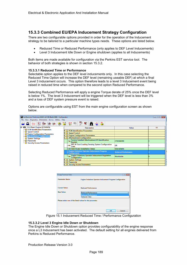
Electrical & Electronic Application And Installation Manual
Production Release Version 3.0 Page 189
15.3.3 Combined EU/EPA Inducement Strategy Configuration There are two configurable options provided in order for the operation of the Inducement strategy to be tailored to a particular machine types needs. These options are listed below.
• Reduced Time or Reduced Performance (only applies to DEF Level Inducements)
• Level 3 Inducement Idle Down or Engine shutdown (applies to all Inducements) Both items are made available for configuration via the Perkins EST service tool. The behavior of both strategies is shown in section 15.3.2. 15.3.3.1 Reduced Time or Performance Selectable option applies to the DEF level inducements only. In this case selecting the Reduced Time Option will increase the DEF level (remaining useable DEF) at which a final Level 3 inducement occurs. This option therefore leads to a level 3 Inducement event being raised in reduced time when compared to the second option Reduced Performance. Selecting Reduced Performance will apply a engine Torque derate of 25% once the DEF level is below 1%. The level 3 Inducement will be triggered when the DEF level is less than 3% and a loss of DEF system pressure event is raised. Options are configurable using EST from the main engine configuration screen as shown below.
Figure 15.1 Inducement Reduced Time / Performance Configuration
15.3.3.2 Level 3 Engine Idle Down or Shutdown The Engine Idle Down or Shutdown option provides configurability of the engine response once a L3 Inducement has been activated. The default setting for all engines delivered from Perkins is Reduced Performance.
Electrical & Electronic Application And Installation Manual
Production Release Version 3.0 Page 190
15.3.4 Repeat Occurrence and Final Inducement Handling
Both Tier 4 Final and Stage IV emissions regulations require specific system reactions to repeat occurrences and persistent failure of an emissions critical component or system. These requirements are covered within the Perkins World Wide inducement strategy as detailed in the following sections. 15.3.4.1 Final Inducement handling In the event of an emissions system fault reaching a Level 3 severity the following actions will take place;
• Level 3 criteria must be active for 20sec before any Inducement is activated.
• After 20sec the engine will proceed to the selected level 3 inducement i.e. one of the following; - 5-min cool down at low idle / 50% Torque reduction then shutdown, or - Idle only operation at no load
15.3.4.2 Repeat Fault Occurrence Handling For All emission critical failures covered by the inducement strategy other than DEF level, there is a requirement for repeat occurrences of faults to be monitored. To meet the legislation requirements Perkins engines will monitor for a repeat occurrence of a fault for 40hrs after the fault condition is healed. If a system fault occurs within the same category within 40hrs the times for warning and inducements as shown in sections 14.3.2.1 to 14.3.3.3 will be reduced (indicated by the Inducement Time Repeat Occurrence row).
15.3.5 Final Inducement Safe Harbor Mode.
Safe harbor mode is a mode of operation that allows for full engine torque capability post Inducement Level 3 activation for a limited time period. This strategy is designed to allow a machine that has been forced to low idle or shutdown due to a system failure causing a Level 3 inducement to be moved to an area where re work can take place. Once the final inducement has been completed (section 15.3.4.1) the first ignition key switch cycle after this event will enable the safe harbor strategy. Once active the following applies;
• Strategy is active for 20 minutes only and timer is NOT reset by cycling the ignition key switch.
• During the 20 minutes of safe harbor mode the engine can be turn off and re started as many times as required
• After 20 minutes the engine will revert back to Level 3 inducement handling i.e. 5 min cooldown at Low idle with 50% Torque reduction then shutdown or idle.
Note: Safe harbor mode does not apply to DEF Level Inducements.
15.3.6 Engine First Fit Inducement Activation To ensure Inducement diagnostics are not false triggered during machine assembly the 1204F and 1206F product range are shipped with Inducements disabled. No ET configuration is required to enable the engine inducements once machine assembly has been completed. The automatic enablement of the Inducement strategy is based on either of the following criteria being met.
• Engine running exceeds 25hrs (initiated from first engine start and does not reset on key cycle)
• System has been detected (by Engine control system) as fault free for 2hrs of engine running time.

Electrical & Electronic Application And Installation Manual
Production Release Version 3.0 Page 191
Note: In order to protect the 1204F DEF cooled injector from damage due to a lack of DEF fluid or disabled dosing system the engine will invoke a 100% engine derate once the engine exhaust SCR Inlet temperature exceeds 200DegC. This code will remain active until the fault is fixed or an ignition key cycle is performed.
15.3.7 Emergency Inducement Override Strategy
At present this strategy is under development and at the time of writing the machine interface requirements have not yet been approved.
Electrical & Electronic Application And Installation Manual
Production Release Version 3.0 Page 192
16.0 Monitored Inputs For Customer Fitted Sensors This section covers the optional switches and sensors available for the customer to install / connect. Some of the switches and sensors require the customer to both install them and provide the wiring harness connection to the engine ECM. Others are factory fitted and require the customer to provide a connection to the ECM only. It should also be noted that not all switches and sensors are available across the product range, these components are highlighted in table 16.1.
Component Engine Range
Part No Customer Fit Component Type
Air Intake Restriction
All T400039 Yes Switch
Engine Coolant Level
All T400042 Yes Switch
Water In Fuel All (Mandatory)
Supplied No Mandatory Switch
Auxiliary Temperature
All T400032 Yes Passive Sensor
Auxiliary Pressure All T400040 Yes Active Sensor
Table 16.1 Customer Installation Monitored Inputs
Each switch / sensor can be individually configured to provide the desired level of monitoring via the standard monitoring system parameters as described in section 14. It should be noted that not all sensors and switches offer all 3 severity levels of monitoring as shown in table 16.2.
Component Input State De bounce Time (secs)
Severity Level Support
J1 Pin Assignment
L1 L2 L3
Air Intake Restriction
SW Batt+
Normally Open
10 Yes Yes No J1-78
Engine Coolant Level Low
SWG Normally Closed
30 Yes No Yes J1-60
Water in Fuel Active Analog
Normally Open
30 Yes No No J1-76
Auxiliary Temp
Passive Analog
N/A Configurable 1 to 120sec
Yes Yes Yes J1-33
Auxiliary Pressure
Active Analog
N/A Configurable 1 to 120sec
Yes Yes Yes J1-61
Table 16.2 Monitored Inputs Detailed Support
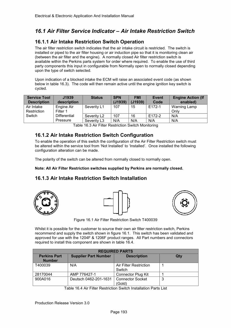
Electrical & Electronic Application And Installation Manual
Production Release Version 3.0 Page 193
16.1 Air Filter Service Indicator – Air Intake Restriction Switch
16.1.1 Air Intake Restriction Switch Operation
The air filter restriction switch indicates that the air intake circuit is restricted. The switch is installed or piped to the air filter housing or air induction pipe so that it is monitoring clean air (between the air filter and the engine). A normally closed Air filter restriction switch is available within the Perkins parts system for order where required. To enable the use of third party components this input in configurable from Normally open to normally closed depending upon the type of switch selected. Upon indication of a blocked intake the ECM will raise an associated event code (as shown below in table 16.3). The code will then remain active until the engine ignition key switch is cycled.
Service Tool Description
J1939 description
Status SPN (J1939)
FMI (J1939)
Event Code
Engine Action (If enabled)
Air Intake Restriction Switch
Engine Air Filter 1 Differential Pressure
Severity L1 107 15 E172-1 Warning Lamp Only
Severity L2 107 16 E172-2 N/A
Severity L3 N/A N/A N/A N/A
Table 16.3 Air Filter Restriction Switch Monitoring
16.1.2 Air Intake Restriction Switch Configuration
To enable the operation of this switch the configuration of the Air Filter Restriction switch must be altered within the service tool from ‘Not Installed’ to ‘Installed’. Once installed the following configuration alteration can be made. The polarity of the switch can be altered from normally closed to normally open. Note: All Air Filter Restriction switches supplied by Perkins are normally closed.
16.1.3 Air Intake Restriction Switch Installation
Figure 16.1 Air Filter Restriction Switch T400039
Whilst it is possible for the customer to source their own air filter restriction switch, Perkins recommend and supply the switch shown in figure 16.1. This switch has been validated and approved for use with the 1204F & 1206F product ranges. All Part numbers and connectors required to install this component are shown in table 16.4.
REQUIRED PARTS
Perkins Part Number
Supplier Part Number Description Qty
T400039 N/A Air Filter Restriction Switch
1
28170044 AMP 776427-1 Connector Plug Kit 1
900A016 Deutsch 0462-201-1631 Connector Socket (Gold)
3
Table 16.4 Air Filter Restriction Switch Installation Parts List
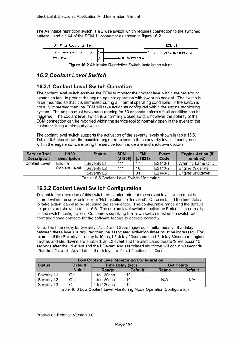
Electrical & Electronic Application And Installation Manual
Production Release Version 3.0 Page 194
The Air intake restriction switch is a 2 wire switch which requires connection to the switched battery + and pin 64 of the ECM J1 connector as shown in figure 16.2.
Figure 16.2 Air Intake Restriction Switch Installation wiring
16.2 Coolant Level Switch
16.2.1 Coolant Level Switch Operation
The coolant level switch enables the ECM to monitor the coolant level within the radiator or expansion tank to protect the engine against operation with low or no coolant. The switch is to be mounted so that it is immersed during all normal operating conditions. If the switch is not fully immersed then the ECM will take action as configured within the engine monitoring system. The engine must have been running for 60 seconds before a fault condition can be triggered. The coolant level switch is a normally closed switch, however the polarity of the ECM connection can be modified within the service tool to normally open in the event of the customer fitting a third party switch. The coolant level switch supports the activation of the severity levels shown in table 16.5. Table 16.5 also shows the possible engine reactions to these severity levels if configured within the engine software using the service tool, i.e. derate and shutdown options.
Service Tool Description
J1939 description
Status SPN (J1939)
FMI (J1939)
Event Code
Engine Action (If enabled)
Coolant Level Engine Coolant Level
Severity L1 111 17 E2143-1 Warning Lamp Only
Severity L2 111 18 E2143-2 Engine % derate
Severity L3 111 01 E2143-3 Engine Shutdown
Table 16.5 Coolant Level Switch Monitoring
16.2.2 Coolant Level Switch Configuration
To enable the operation of this switch the configuration of the coolant level switch must be altered within the service tool from ‘Not Installed’ to ‘Installed’. Once installed the time delay to ‘take action’ can also be set using the service tool. The configurable range and the default set points are shown in table 16.6. The coolant level switch supplied by Perkins is a normally closed switch configuration. Customers supplying their own switch must use a switch with normally closed contacts for the software feature to operate correctly. Note: The time delay for Severity L1, L2 and L3 are triggered simultaneously. If a delay between these levels is required then the associated activation times must be increased. For example if the Severity L1 delay is 10sec, L2 delay 20sec and the L3 delay 30sec and engine derates and shutdowns are enabled, an L2 event and the associated derate % will occur 10 seconds after the L1 event and the L3 event and associated shutdown will occur 10 seconds after the L2 event. As a default the delay time for all functions is 10sec.
Low Coolant Level Monitoring Configuration
Status Default Value
Time Delay (sec) Set Points
Range Default Range Default
Severity L1 On 1 to 120sec 10
N/A N/A Severity L2 On 1 to 120sec 10
Severity L3 Off 1 to 120sec 10
Table 16.6 Low Coolant Level Monitoring Mode Operation Configuration
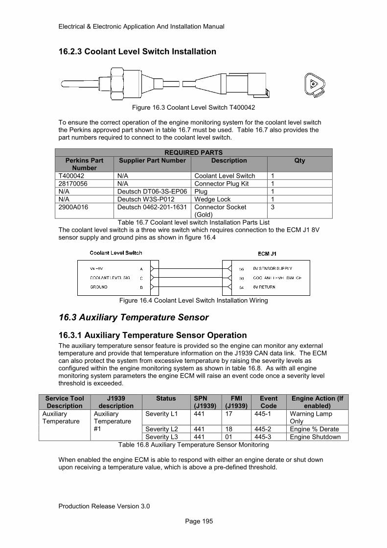
Electrical & Electronic Application And Installation Manual
Production Release Version 3.0 Page 195
16.2.3 Coolant Level Switch Installation
Figure 16.3 Coolant Level Switch T400042 To ensure the correct operation of the engine monitoring system for the coolant level switch the Perkins approved part shown in table 16.7 must be used. Table 16.7 also provides the part numbers required to connect to the coolant level switch.
REQUIRED PARTS
Perkins Part Number
Supplier Part Number Description Qty
T400042 N/A Coolant Level Switch 1
28170056 N/A Connector Plug Kit 1
N/A Deutsch DT06-3S-EP06 Plug 1
N/A Deutsch W3S-P012 Wedge Lock 1
2900A016 Deutsch 0462-201-1631 Connector Socket (Gold)
3
Table 16.7 Coolant level switch Installation Parts List The coolant level switch is a three wire switch which requires connection to the ECM J1 8V sensor supply and ground pins as shown in figure 16.4
Figure 16.4 Coolant Level Switch Installation Wiring
16.3 Auxiliary Temperature Sensor
16.3.1 Auxiliary Temperature Sensor Operation The auxiliary temperature sensor feature is provided so the engine can monitor any external temperature and provide that temperature information on the J1939 CAN data link. The ECM can also protect the system from excessive temperature by raising the severity levels as configured within the engine monitoring system as shown in table 16.8. As with all engine monitoring system parameters the engine ECM will raise an event code once a severity level threshold is exceeded.
Service Tool Description
J1939 description
Status SPN (J1939)
FMI (J1939)
Event Code
Engine Action (If enabled)
Auxiliary Temperature
Auxiliary Temperature #1
Severity L1 441 17 445-1 Warning Lamp Only
Severity L2 441 18 445-2 Engine % Derate
Severity L3 441 01 445-3 Engine Shutdown
Table 16.8 Auxiliary Temperature Sensor Monitoring
When enabled the engine ECM is able to respond with either an engine derate or shut down upon receiving a temperature value, which is above a pre-defined threshold.
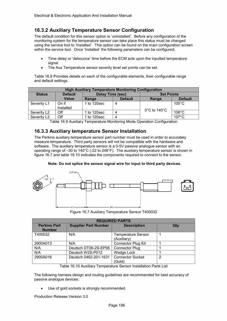
Electrical & Electronic Application And Installation Manual
Production Release Version 3.0 Page 196
16.3.2 Auxiliary Temperature Sensor Configuration
The default condition for this sensor option is ‘uninstalled’. Before any configuration of the monitoring system for the temperature sensor can take place this status must be changed using the service tool to ‘Installed’. This option can be found on the main configuration screen within the service tool. Once ‘Installed’ the following parameters can be configured;
• Time delay or ‘debounce’ time before the ECM acts upon the inputted temperature signal.
• The Aux Temperature sensor severity level set points can be set. Table 16.9 Provides details on each of the configurable elements, their configurable range and default settings.
High Auxiliary Temperature Monitoring Configuration
Status Default Value
Delay Time (sec) Set Points
Range Default Range Default
Severity L1 On if Installed
1 to 120sec 4
0°C to 140°C
105°C
Severity L2 Off 1 to 120sec 4 106°C
Severity L3 Off 1 to 120sec 4 107°C
Table 16.9 Auxiliary Temperature Monitoring Mode Operation Configuration
16.3.3 Auxiliary temperature Sensor Installation
The Perkins auxiliary temperature sensor part number must be used in order to accurately measure temperature. Third party sensors will not be compatible with the hardware and software. The auxiliary temperature sensor is a 0-5V passive analogue sensor with an operating range of –30 to 140°C (-22 to 248°F). The auxiliary temperature sensor is shown in figure 16.7 and table 16.10 indicates the components required to connect to the sensor.
Note: Do not splice the sensor signal wire for input to third party devices.
Figure 16.7 Auxiliary Temperature Sensor T400032
REQUIRED PARTS
Perkins Part Number
Supplier Part Number Description Qty
T400032 N/A Temperature Sensor (Auxiliary)
1
2900A013 N/A Connector Plug Kit 1
N/A Deutsch DT06-2S-EP06 Connector Plug 1
N/A Deutsch W2S-P012 Wedge Lock 1
2900A016 Deutsch 0462-201-1631 Connector Socket (Gold)
2
Table 16.10 Auxiliary Temperature Sensor Installation Parts List The following harness design and routing guidelines are recommended for best accuracy of passive analogue devices:
• Use of gold sockets is strongly recommended.
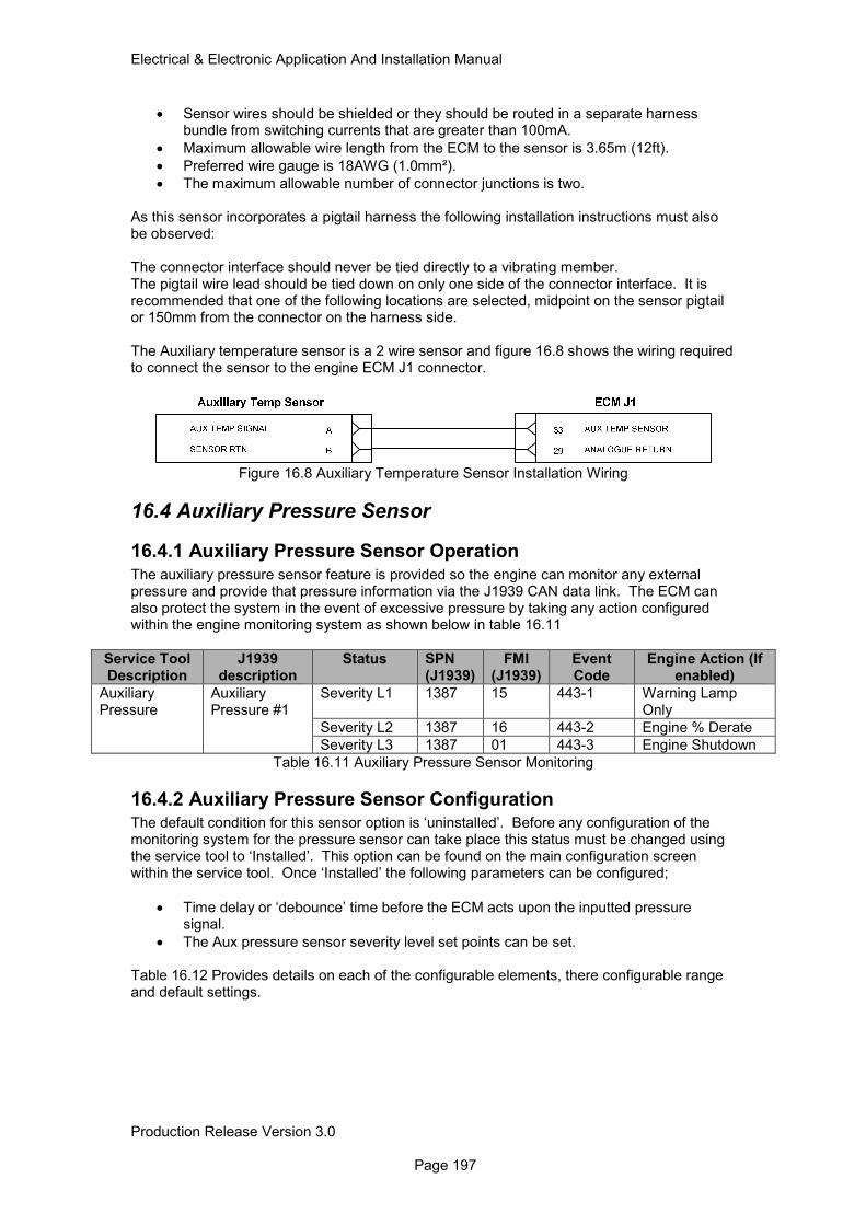
Electrical & Electronic Application And Installation Manual
Production Release Version 3.0 Page 197
• Sensor wires should be shielded or they should be routed in a separate harness bundle from switching currents that are greater than 100mA.
• Maximum allowable wire length from the ECM to the sensor is 3.65m (12ft).
• Preferred wire gauge is 18AWG (1.0mm²).
• The maximum allowable number of connector junctions is two. As this sensor incorporates a pigtail harness the following installation instructions must also be observed: The connector interface should never be tied directly to a vibrating member. The pigtail wire lead should be tied down on only one side of the connector interface. It is recommended that one of the following locations are selected, midpoint on the sensor pigtail or 150mm from the connector on the harness side. The Auxiliary temperature sensor is a 2 wire sensor and figure 16.8 shows the wiring required to connect the sensor to the engine ECM J1 connector.
Figure 16.8 Auxiliary Temperature Sensor Installation Wiring
16.4 Auxiliary Pressure Sensor
16.4.1 Auxiliary Pressure Sensor Operation
The auxiliary pressure sensor feature is provided so the engine can monitor any external pressure and provide that pressure information via the J1939 CAN data link. The ECM can also protect the system in the event of excessive pressure by taking any action configured within the engine monitoring system as shown below in table 16.11
Service Tool Description
J1939 description
Status SPN (J1939)
FMI (J1939)
Event Code
Engine Action (If enabled)
Auxiliary Pressure
Auxiliary Pressure #1
Severity L1 1387 15 443-1 Warning Lamp Only
Severity L2 1387 16 443-2 Engine % Derate
Severity L3 1387 01 443-3 Engine Shutdown
Table 16.11 Auxiliary Pressure Sensor Monitoring
16.4.2 Auxiliary Pressure Sensor Configuration The default condition for this sensor option is ‘uninstalled’. Before any configuration of the monitoring system for the pressure sensor can take place this status must be changed using the service tool to ‘Installed’. This option can be found on the main configuration screen within the service tool. Once ‘Installed’ the following parameters can be configured;
• Time delay or ‘debounce’ time before the ECM acts upon the inputted pressure signal.
• The Aux pressure sensor severity level set points can be set. Table 16.12 Provides details on each of the configurable elements, there configurable range and default settings.
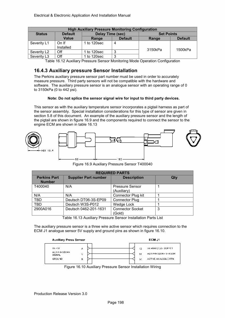
Electrical & Electronic Application And Installation Manual
Production Release Version 3.0 Page 198
High Auxiliary Pressure Monitoring Configuration
Status Default Value
Delay Time (sec) Set Points
Range Default Range Default
Severity L1 On If Installed
1 to 120sec 4
3150kPa 1500kPa Severity L2 Off 1 to 120sec 3
Severity L3 Off 1 to 120sec 3
Table 16.12 Auxiliary Pressure Sensor Monitoring Mode Operation Configuration
16.4.3 Auxiliary pressure Sensor Installation The Perkins auxiliary pressure sensor part number must be used in order to accurately measure pressure. Third party sensors will not be compatible with the hardware and software. The auxiliary pressure sensor is an analogue sensor with an operating range of 0 to 3150kPa (0 to 442 psi).
Note: Do not splice the sensor signal wire for input to third party devices. This sensor as with the auxiliary temperature sensor incorporates a pigtail harness as part of the sensor assembly. Special installation considerations for this type of sensor are given in section 5.8 of this document. An example of the auxiliary pressure sensor and the length of the pigtail are shown in figure 16.9 and the components required to connect the sensor to the engine ECM are shown in table 16.13
Figure 16.9 Auxiliary Pressure Sensor T400040
REQUIRED PARTS
Perkins Part Number
Supplier Part number Description Qty
T400040 N/A Pressure Sensor (Auxiliary)
1
N/A N/A Connector Plug kit 1
TBD Deutsch DT06-3S-EP09 Connector Plug 1
TBD Deutsch W3S-P012 Wedge Lock 1
2900A016 Deutsch 0462-201-1631 Connector Socket (Gold)
3
Table 16.13 Auxiliary Pressure Sensor Installation Parts List
The auxiliary pressure sensor is a three wire active sensor which requires connection to the ECM J1 analogue sensor 5V supply and ground pins as shown in figure 16.10.
Figure 16.10 Auxiliary Pressure Sensor Installation Wiring
Electrical & Electronic Application And Installation Manual
Production Release Version 3.0 Page 199
17.0 Aftertreatment System Machine Integration
17.1 Aftertreatment System Operation The Perkins 1204F & 1206F product ranges use various combinations of aftertreatment technologies. In each case the chosen technologies have been selected as the optimal combination to meet the Tier 4 Final/Stage IV emissions standards. The table below provides details of the 1204F to 1206F product configurations.
Tier 4F Aftertreatment Technology
Engine Power Kw Aftertreatment Regeneration
1204F 70 - 110 DOC / SCR Low Temp Regen
1204F 105 - 130 DOC / SCR Low Temp Regen
1204F 105 - 130 DOC/DPF/SCR Low Temp Regen
1206F 116 - 151 DOC/DPF/SCR Low Temp Regen
1206F 151 - 225 DOC/DPF/SCR Low Temp Regen
Table 17.1 Tier 4F Aftertreatment Technology
17.1.1 DOC Operation The DOC consists of a ceramic substrate coated with an oxide mixture and a catalyzing metal. The engine DOC is required to perform the following functions;
• Remove CO and HC portions of the engine exhaust gas.
• Oxidize NO to NO2 to help reactions at both the DPF and SCR.
17.1.2 DPF Operation
The Diesel particulate filter is required to capture and then remove soot particles (via oxidation) from the engine exhaust via low temperature regeneration.
17.1.3 SCR Operation The SCR unit or Selective catalyst reduction unit is required to specifically target the removal or conversion of NOx particles into N2, H2O and CO2.
17.2 Low Temperature Aftertreatment Regeneration System All Tier 4 Final/Stage IV 1200 series products are supplied from the factory fitted with an exhaust backpressure valve as standard to aid exhaust system thermal management. One of the main uses of the exhaust backpressure valve during engine operation is to provide sufficient exhaust temperature for the regeneration of the Aftertreatment system.
17.2.1 Low Speed Regeneration Operation 1204F DOC + SCR only
For the applications prone to operating at low loads for prolonged periods of time, an aftertreatment regeneration event could be required. For the no DPF product this regeneration event is focused on overall aftertreatment system temperature (thermal management) to maintain system performance, unlike the DPF engines where regeneration also covers DPF soot removal. The aftertreatment regeneration strategy uses control functionality which continually monitors the health of the aftertreatment system, employing measures to artificially elevate exhaust system temperatures when necessary. This strategy will usually operate at the normal idle speed of the application and without any operator interaction; however, under some conditions when circumstances do not allow sufficient temperature increase, the strategy will demand an elevated engine speed up to 1200rpm.
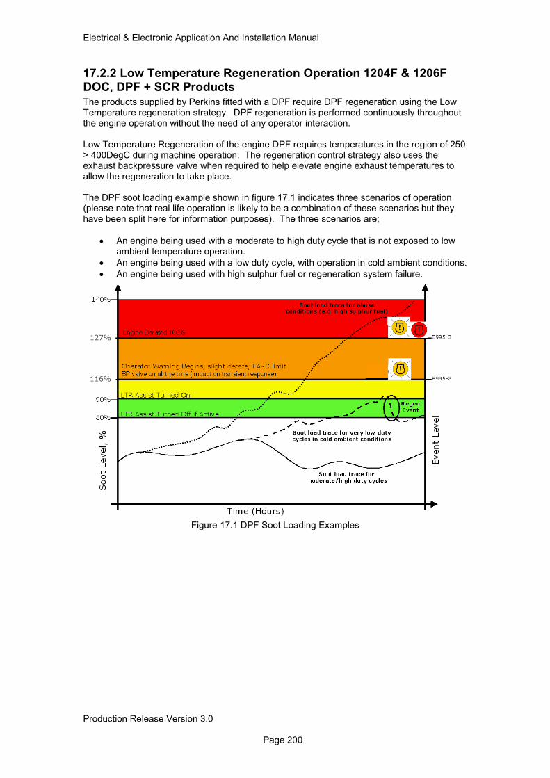
Electrical & Electronic Application And Installation Manual
Production Release Version 3.0 Page 200
17.2.2 Low Temperature Regeneration Operation 1204F & 1206F DOC, DPF + SCR Products The products supplied by Perkins fitted with a DPF require DPF regeneration using the Low Temperature regeneration strategy. DPF regeneration is performed continuously throughout the engine operation without the need of any operator interaction. Low Temperature Regeneration of the engine DPF requires temperatures in the region of 250 > 400DegC during machine operation. The regeneration control strategy also uses the exhaust backpressure valve when required to help elevate engine exhaust temperatures to allow the regeneration to take place. The DPF soot loading example shown in figure 17.1 indicates three scenarios of operation (please note that real life operation is likely to be a combination of these scenarios but they have been split here for information purposes). The three scenarios are;
• An engine being used with a moderate to high duty cycle that is not exposed to low ambient temperature operation.
• An engine being used with a low duty cycle, with operation in cold ambient conditions.
• An engine being used with high sulphur fuel or regeneration system failure.
Figure 17.1 DPF Soot Loading Examples
116%
127%
Electrical & Electronic Application And Installation Manual
Production Release Version 3.0 Page 201
Table 17.2 describes the system operation as the DPF soot loading increases and decreases throughout the monitoring system loading categories.
DPF Soot Load
System Description Engine % Derate
Lamp status
0 < 79% From 0 to 79% soot loading applications requiring a moderate to high duty cycle should regenerate without any control system intervention. In some cases (low duty cycle or cold ambient) to DPF soot loading may exceed 79%.
N/A N/A
80 < 89% The Low Temperature regeneration system may take action to oxidize soot, depending on the machine operating conditions.
N/A N/A
90 < 115% Back pressure valve is operated as required. The back pressure valve is disabled as soon as the soot loading reduces to 79% or below.
116 < 126% The low temperature regeneration system takes more aggressive actions to attempt to reduce soot load. The engine will derate starting at 50% and rising to 100% when the soot load reaches 127%. The engine management system raises an event code once the soot load reaches 116% (E995-2) which activates the engine warning lamp. The lamp remain active until the DPF soot load is below 106%.
Engine derate 50% @ 116% rising to 100% @ 127%
Slow Flashing Engine Warning Lamp
127 < 140% Once the engine exceeds 127% the engine will be 100% derated and an event code (E955-3) is raised. Both the warning and shutdown lamps are also operated.
100%
Fast Flashing engine Warning Lamp
Engine Shutdown Lamp
Table 17.2 Low Temperature Regeneration Operation Description
!
!
!
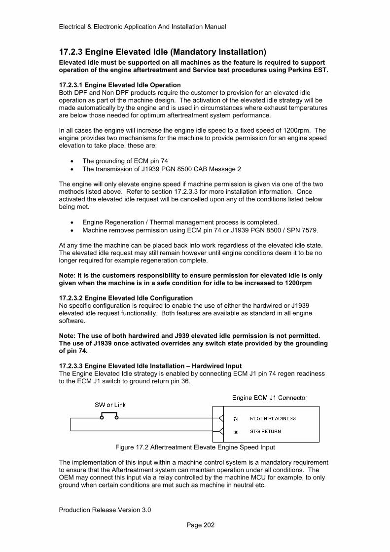
Electrical & Electronic Application And Installation Manual
Production Release Version 3.0 Page 202
17.2.3 Engine Elevated Idle (Mandatory Installation) Elevated idle must be supported on all machines as the feature is required to support operation of the engine aftertreatment and Service test procedures using Perkins EST. 17.2.3.1 Engine Elevated Idle Operation Both DPF and Non DPF products require the customer to provision for an elevated idle operation as part of the machine design. The activation of the elevated idle strategy will be made automatically by the engine and is used in circumstances where exhaust temperatures are below those needed for optimum aftertreatment system performance. In all cases the engine will increase the engine idle speed to a fixed speed of 1200rpm. The engine provides two mechanisms for the machine to provide permission for an engine speed elevation to take place, these are;
• The grounding of ECM pin 74
• The transmission of J1939 PGN 8500 CAB Message 2 The engine will only elevate engine speed if machine permission is given via one of the two methods listed above. Refer to section 17.2.3.3 for more installation information. Once activated the elevated idle request will be cancelled upon any of the conditions listed below being met.
• Engine Regeneration / Thermal management process is completed.
• Machine removes permission using ECM pin 74 or J1939 PGN 8500 / SPN 7579. At any time the machine can be placed back into work regardless of the elevated idle state. The elevated idle request may still remain however until engine conditions deem it to be no longer required for example regeneration complete. Note: It is the customers responsibility to ensure permission for elevated idle is only given when the machine is in a safe condition for idle to be increased to 1200rpm 17.2.3.2 Engine Elevated Idle Configuration No specific configuration is required to enable the use of either the hardwired or J1939 elevated idle request functionality. Both features are available as standard in all engine software. Note: The use of both hardwired and J939 elevated idle permission is not permitted. The use of J1939 once activated overrides any switch state provided by the grounding of pin 74. 17.2.3.3 Engine Elevated Idle Installation – Hardwired Input The Engine Elevated Idle strategy is enabled by connecting ECM J1 pin 74 regen readiness to the ECM J1 switch to ground return pin 36.
Figure 17.2 Aftertreatment Elevate Engine Speed Input
The implementation of this input within a machine control system is a mandatory requirement to ensure that the Aftertreatment system can maintain operation under all conditions. The OEM may connect this input via a relay controlled by the machine MCU for example, to only ground when certain conditions are met such as machine in neutral etc.
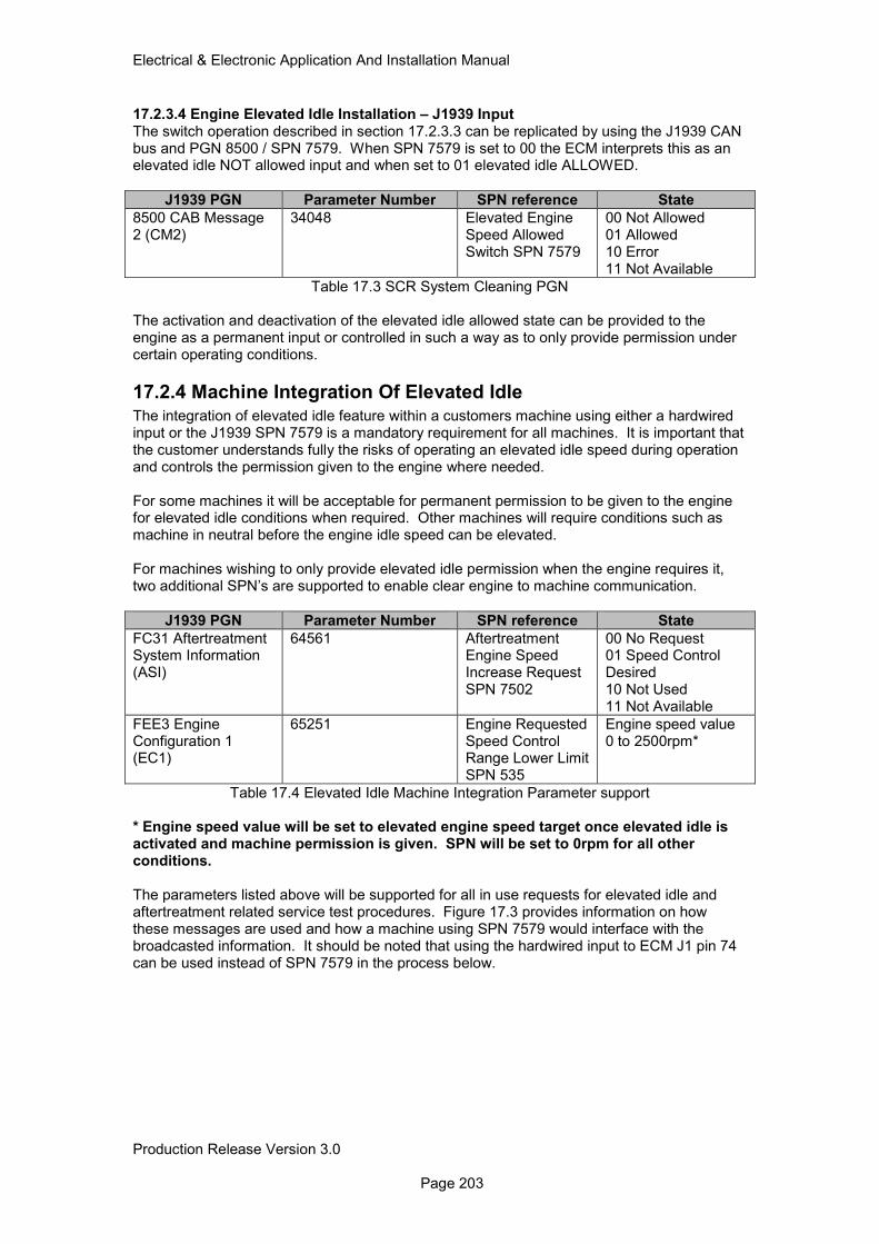
Electrical & Electronic Application And Installation Manual
Production Release Version 3.0 Page 203
17.2.3.4 Engine Elevated Idle Installation – J1939 Input The switch operation described in section 17.2.3.3 can be replicated by using the J1939 CAN bus and PGN 8500 / SPN 7579. When SPN 7579 is set to 00 the ECM interprets this as an elevated idle NOT allowed input and when set to 01 elevated idle ALLOWED.
J1939 PGN Parameter Number SPN reference State
8500 CAB Message 2 (CM2)
34048 Elevated Engine Speed Allowed Switch SPN 7579
00 Not Allowed 01 Allowed 10 Error 11 Not Available
Table 17.3 SCR System Cleaning PGN The activation and deactivation of the elevated idle allowed state can be provided to the engine as a permanent input or controlled in such a way as to only provide permission under certain operating conditions.
17.2.4 Machine Integration Of Elevated Idle The integration of elevated idle feature within a customers machine using either a hardwired input or the J1939 SPN 7579 is a mandatory requirement for all machines. It is important that the customer understands fully the risks of operating an elevated idle speed during operation and controls the permission given to the engine where needed. For some machines it will be acceptable for permanent permission to be given to the engine for elevated idle conditions when required. Other machines will require conditions such as machine in neutral before the engine idle speed can be elevated. For machines wishing to only provide elevated idle permission when the engine requires it, two additional SPN’s are supported to enable clear engine to machine communication.
J1939 PGN Parameter Number SPN reference State
FC31 Aftertreatment System Information (ASI)
64561 Aftertreatment Engine Speed Increase Request SPN 7502
00 No Request 01 Speed Control Desired 10 Not Used 11 Not Available
FEE3 Engine Configuration 1 (EC1)
65251 Engine Requested Speed Control Range Lower Limit SPN 535
Engine speed value 0 to 2500rpm*
Table 17.4 Elevated Idle Machine Integration Parameter support * Engine speed value will be set to elevated engine speed target once elevated idle is activated and machine permission is given. SPN will be set to 0rpm for all other conditions. The parameters listed above will be supported for all in use requests for elevated idle and aftertreatment related service test procedures. Figure 17.3 provides information on how these messages are used and how a machine using SPN 7579 would interface with the broadcasted information. It should be noted that using the hardwired input to ECM J1 pin 74 can be used instead of SPN 7579 in the process below.
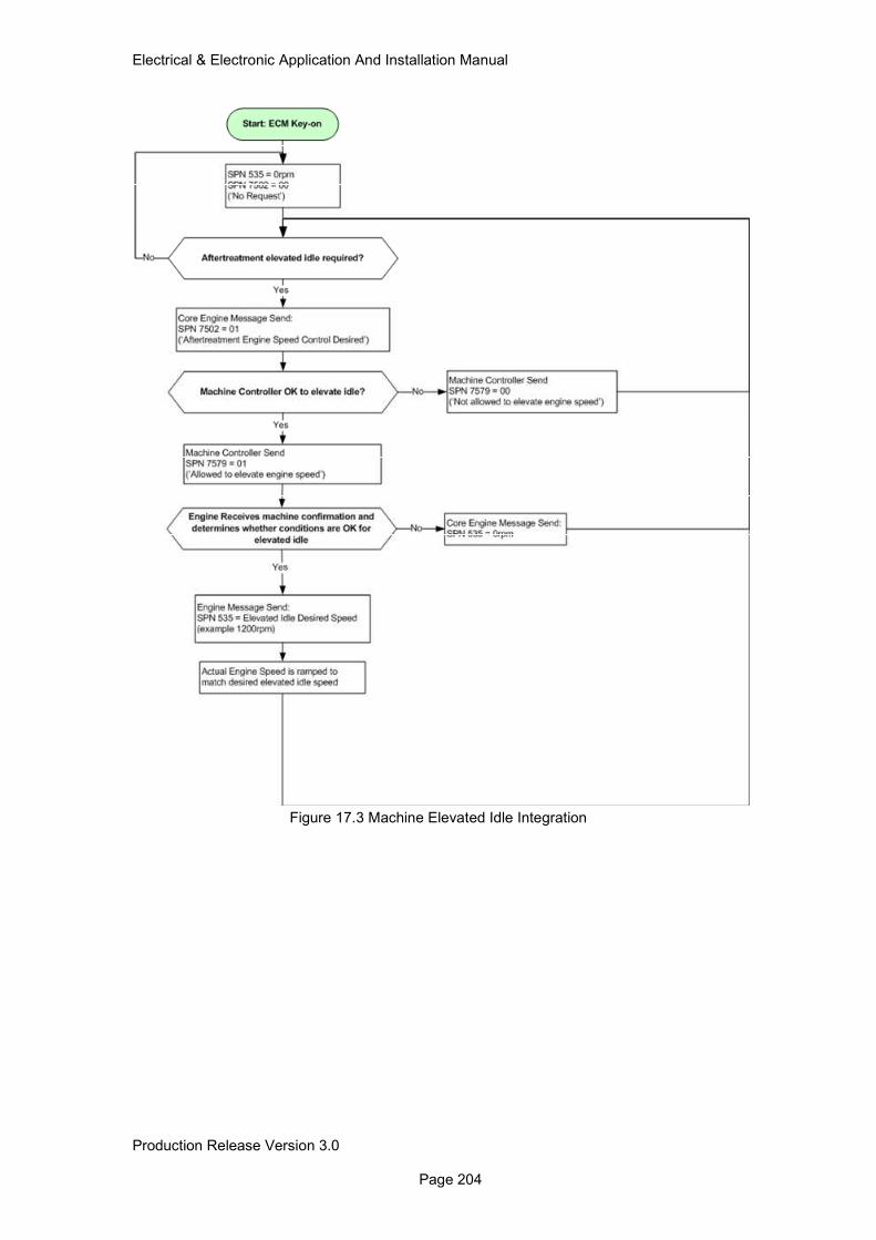
Electrical & Electronic Application And Installation Manual
Production Release Version 3.0 Page 204
Figure 17.3 Machine Elevated Idle Integration
Electrical & Electronic Application And Installation Manual
Production Release Version 3.0 Page 205
17.3 DEF System Operation The Tier 4F DEF system is designed to provide optimum DEF dosing and control performance. Each system is made up of the following components:
• DEF Pump
• DEF Controller or DCU
• DEF Tank
• Heated Lines x 3
• DEF Tank Header (for temp, level and quality sensors)
• Engine Coolant diverter valve In all cases the engine ECM is used to control the activation of the DEF dosing strategy and metering requirements. The local DCU controller provides the individual system component control such as line heater activation and direct DEF injector control. The engine ECM uses information taken from system temperature sensors, NOx monitoring hardware and software models to determine the required DEF dosing rate as well as the boundary conditions for activation. An example of the DEF system control during a normal engine work cycle is shown in figure 17.3
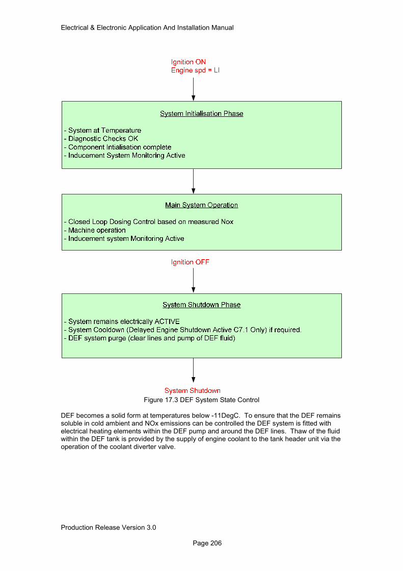
Electrical & Electronic Application And Installation Manual
Production Release Version 3.0 Page 206
Figure 17.3 DEF System State Control
DEF becomes a solid form at temperatures below -11DegC. To ensure that the DEF remains soluble in cold ambient and NOx emissions can be controlled the DEF system is fitted with electrical heating elements within the DEF pump and around the DEF lines. Thaw of the fluid within the DEF tank is provided by the supply of engine coolant to the tank header unit via the operation of the coolant diverter valve.
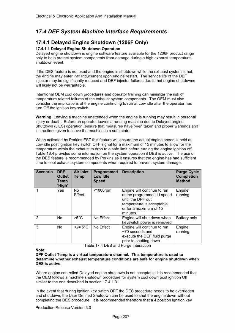
Electrical & Electronic Application And Installation Manual
Production Release Version 3.0 Page 207
17.4 DEF System Machine Interface Requirements
17.4.1 Delayed Engine Shutdown (1206F Only) 17.4.1.1 Delayed Engine Shutdown Operation Delayed engine shutdown is engine software feature available for the 1206F product range only to help protect system components from damage during a high exhaust temperature shutdown event. If the DES feature is not used and the engine is shutdown while the exhaust system is hot, the engine may enter into Inducement upon engine restart. The service life of the DEF injector may be significantly reduced and DEF injector failures due to hot engine shutdowns will likely not be warrantable. Intentional OEM cool down procedures and operator training can minimize the risk of temperature related failures of the exhaust system components. The OEM must also consider the implications of the engine continuing to run at Low idle after the operator has turn Off the ignition key switch. Warning: Leaving a machine unattended when the engine is running may result in personal injury or death. Before an operator leaves a running machine due to Delayed engine Shutdown (DES) operation, ensure that measures have been taken and proper warnings and instructions given to leave the machine in a safe state. When activated by Perkins EST this feature will ensure the actual engine speed is held at Low idle post ignition key switch OFF signal for a maximum of 15 minutes to allow for the temperature within the exhaust to drop to a safe limit before turning the engine ignition off. Table 16.4 provides some information on the system operation if DES is active. The use of the DES feature is recommended by Perkins as it ensures that the engine has had sufficient time to cool exhaust system components when required to prevent system damage.
Scenario DPF Outlet Temp ‘High’
Air Inlet Temp
Programmed Low Idle Speed
Description Purge Cycle Completion Method
1 Yes No Effect
<1000rpm Engine will continue to run at the programmed LI speed until the DPF out temperature is acceptable or for a maximum of 15 minutes.
Engine running
2 No >5°C No Effect Engine will shut down when keyswitch power is removed
Battery only
3 No <,/= 5°C No Effect Engine will continue to run ~70 seconds and execute the DEF fluid purge prior to shutting down
Engine running
Table 17.4 DES and Purge Interaction Note: DPF Outlet Temp is a virtual temperature channel. This temperature is used to determine whether exhaust temperature conditions are safe for engine shutdown when DES is active. Where engine controlled Delayed engine shutdown is not acceptable it is recommended that the OEM follows a machine shutdown procedure for system cool down post ignition Off similar to the one described in section 17.4.1.3. In the event that during ignition key switch OFF the DES procedure needs to be overridden and shutdown, the User Defined Shutdown can be used to shut the engine down without completing the DES procedure. It is recommended therefore that a 4 position ignition key
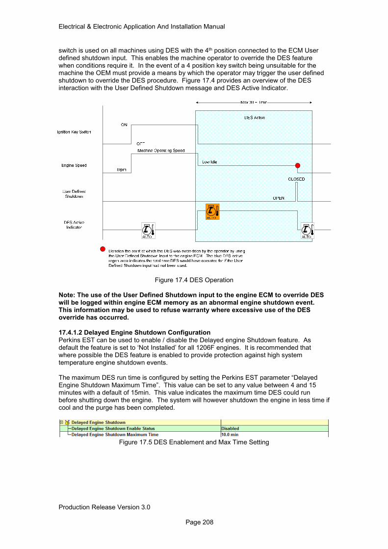
Electrical & Electronic Application And Installation Manual
Production Release Version 3.0 Page 208
switch is used on all machines using DES with the 4th position connected to the ECM User defined shutdown input. This enables the machine operator to override the DES feature when conditions require it. In the event of a 4 position key switch being unsuitable for the machine the OEM must provide a means by which the operator may trigger the user defined shutdown to override the DES procedure. Figure 17.4 provides an overview of the DES interaction with the User Defined Shutdown message and DES Active Indicator.
Figure 17.4 DES Operation
Note: The use of the User Defined Shutdown input to the engine ECM to override DES will be logged within engine ECM memory as an abnormal engine shutdown event. This information may be used to refuse warranty where excessive use of the DES override has occurred. 17.4.1.2 Delayed Engine Shutdown Configuration Perkins EST can be used to enable / disable the Delayed engine Shutdown feature. As default the feature is set to ‘Not Installed’ for all 1206F engines. It is recommended that where possible the DES feature is enabled to provide protection against high system temperature engine shutdown events. The maximum DES run time is configured by setting the Perkins EST parameter “Delayed Engine Shutdown Maximum Time”. This value can be set to any value between 4 and 15 minutes with a default of 15min. This value indicates the maximum time DES could run before shutting down the engine. The system will however shutdown the engine in less time if cool and the purge has been completed.
Figure 17.5 DES Enablement and Max Time Setting
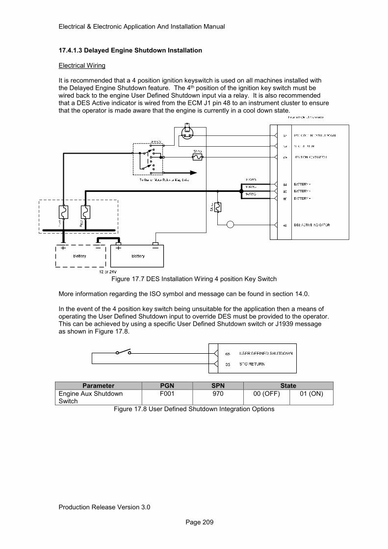
Electrical & Electronic Application And Installation Manual
Production Release Version 3.0 Page 209
17.4.1.3 Delayed Engine Shutdown Installation Electrical Wiring It is recommended that a 4 position ignition keyswitch is used on all machines installed with the Delayed Engine Shutdown feature. The 4th position of the ignition key switch must be wired back to the engine User Defined Shutdown input via a relay. It is also recommended that a DES Active indicator is wired from the ECM J1 pin 48 to an instrument cluster to ensure that the operator is made aware that the engine is currently in a cool down state.
Figure 17.7 DES Installation Wiring 4 position Key Switch
More information regarding the ISO symbol and message can be found in section 14.0. In the event of the 4 position key switch being unsuitable for the application then a means of operating the User Defined Shutdown input to override DES must be provided to the operator. This can be achieved by using a specific User Defined Shutdown switch or J1939 message as shown in Figure 17.8.
Parameter PGN SPN State
Engine Aux Shutdown Switch
F001 970 00 (OFF) 01 (ON)
Figure 17.8 User Defined Shutdown Integration Options
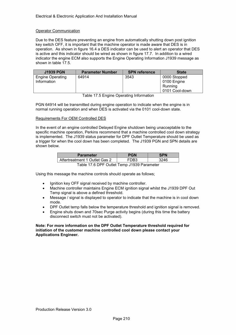
Electrical & Electronic Application And Installation Manual
Production Release Version 3.0 Page 210
Operator Communication Due to the DES feature preventing an engine from automatically shutting down post ignition key switch OFF, it is important that the machine operator is made aware that DES is in operation. As shown in figure 16.4 a DES indicator can be used to alert an operator that DES is active and this indicator should be wired as shown in figure 17.7. In addition to a wired indicator the engine ECM also supports the Engine Operating Information J1939 message as shown in table 17.5.
J1939 PGN Parameter Number SPN reference State
Engine Operating Information
64914 3543 0000 Stopped 0100 Engine Running 0101 Cool-down
Table 17.5 Engine Operating Information PGN 64914 will be transmitted during engine operation to indicate when the engine is in normal running operation and when DES is activated via the 0101 cool-down state. Requirements For OEM Controlled DES In the event of an engine controlled Delayed Engine shutdown being unacceptable to the specific machine operation, Perkins recommend that a machine controlled cool down strategy is implemented. The J1939 status parameter for DPF Outlet Temperature should be used as a trigger for when the cool down has been completed. The J1939 PGN and SPN details are shown below.
Parameter PGN SPN
Aftertreatment 1 Outlet Gas 2 FDB3 3246
Table 17.6 DPF Outlet Temp J1939 Parameter Using this message the machine controls should operate as follows;
• Ignition key OFF signal received by machine controller.
• Machine controller maintains Engine ECM ignition signal whilst the J1939 DPF Out Temp signal is above a defined threshold.
• Message / signal is displayed to operator to indicate that the machine is in cool down mode.
• DPF Outlet temp falls below the temperature threshold and ignition signal is removed.
• Engine shuts down and 70sec Purge activity begins (during this time the battery disconnect switch must not be activated).
Note: For more information on the DPF Outlet Temperature threshold required for initiation of the customer machine controlled cool down please contact your Applications Engineer.
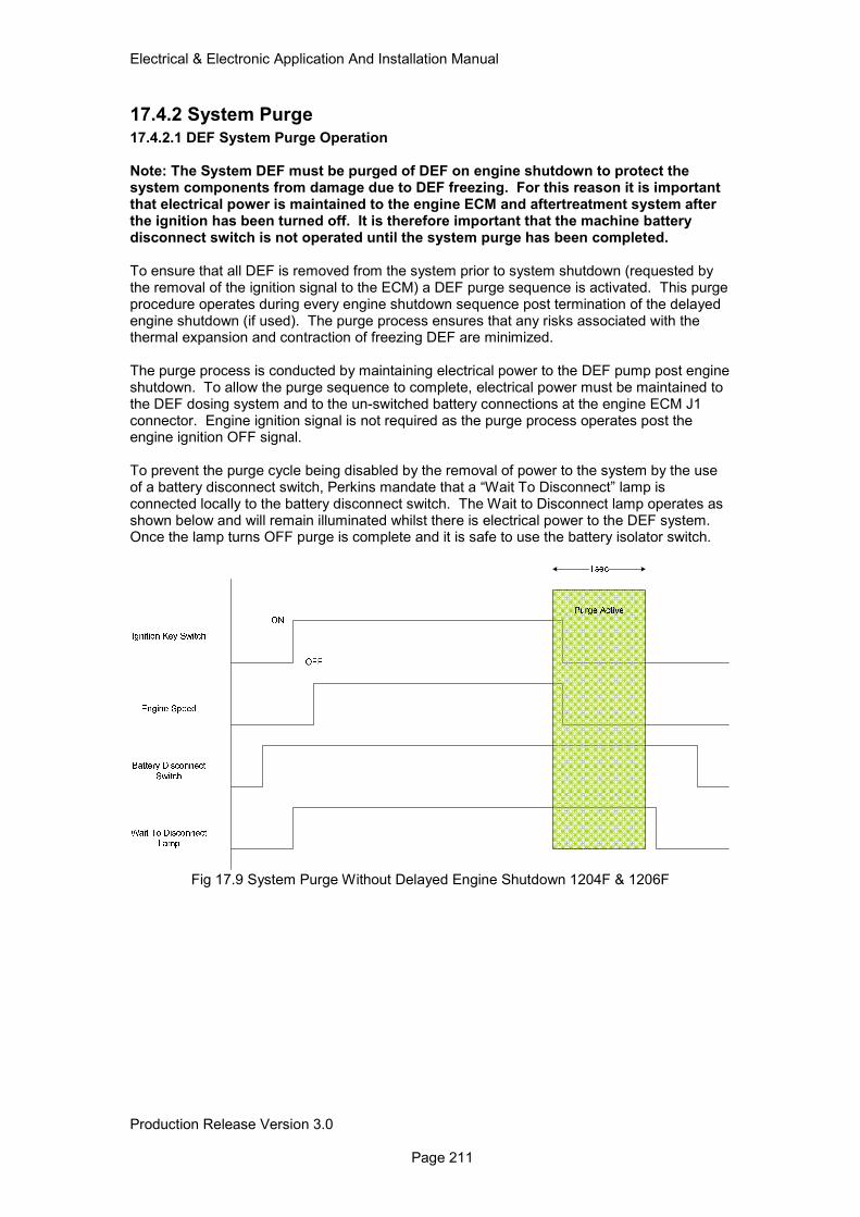
Electrical & Electronic Application And Installation Manual
Production Release Version 3.0 Page 211
17.4.2 System Purge 17.4.2.1 DEF System Purge Operation Note: The System DEF must be purged of DEF on engine shutdown to protect the system components from damage due to DEF freezing. For this reason it is important that electrical power is maintained to the engine ECM and aftertreatment system after the ignition has been turned off. It is therefore important that the machine battery disconnect switch is not operated until the system purge has been completed. To ensure that all DEF is removed from the system prior to system shutdown (requested by the removal of the ignition signal to the ECM) a DEF purge sequence is activated. This purge procedure operates during every engine shutdown sequence post termination of the delayed engine shutdown (if used). The purge process ensures that any risks associated with the thermal expansion and contraction of freezing DEF are minimized. The purge process is conducted by maintaining electrical power to the DEF pump post engine shutdown. To allow the purge sequence to complete, electrical power must be maintained to the DEF dosing system and to the un-switched battery connections at the engine ECM J1 connector. Engine ignition signal is not required as the purge process operates post the engine ignition OFF signal. To prevent the purge cycle being disabled by the removal of power to the system by the use of a battery disconnect switch, Perkins mandate that a “Wait To Disconnect” lamp is connected locally to the battery disconnect switch. The Wait to Disconnect lamp operates as shown below and will remain illuminated whilst there is electrical power to the DEF system. Once the lamp turns OFF purge is complete and it is safe to use the battery isolator switch.
Fig 17.9 System Purge Without Delayed Engine Shutdown 1204F & 1206F
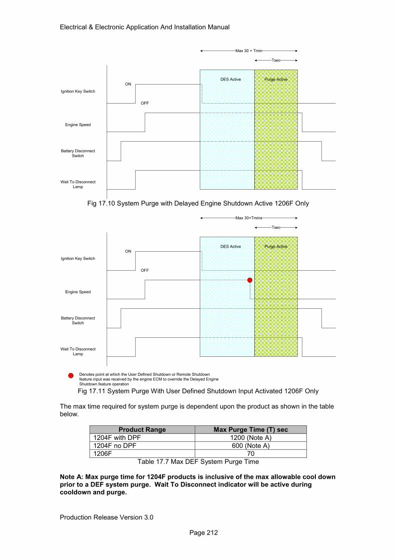
Electrical & Electronic Application And Installation Manual
Production Release Version 3.0 Page 212
Ignition Key Switch
Engine Speed
Battery Disconnect
Switch
Wait To Disconnect
Lamp
ON
OFF
Tsec
Purge Active
Max 30 + Tmin
DES Active
Fig 17.10 System Purge with Delayed Engine Shutdown Active 1206F Only
Ignition Key Switch
Engine Speed
Battery Disconnect
Switch
Wait To Disconnect
Lamp
ON
OFF
Tsec
Purge Active
Max 30+Tmins
DES Active
Denotes point at which the User Defined Shutdown or Remote Shutdown
feature input was received by the engine ECM to override the Delayed Engine
Shutdown feature operation Fig 17.11 System Purge With User Defined Shutdown Input Activated 1206F Only
The max time required for system purge is dependent upon the product as shown in the table below.
Product Range Max Purge Time (T) sec
1204F with DPF 1200 (Note A)
1204F no DPF 600 (Note A)
1206F 70
Table 17.7 Max DEF System Purge Time
Note A: Max purge time for 1204F products is inclusive of the max allowable cool down prior to a DEF system purge. Wait To Disconnect indicator will be active during cooldown and purge.
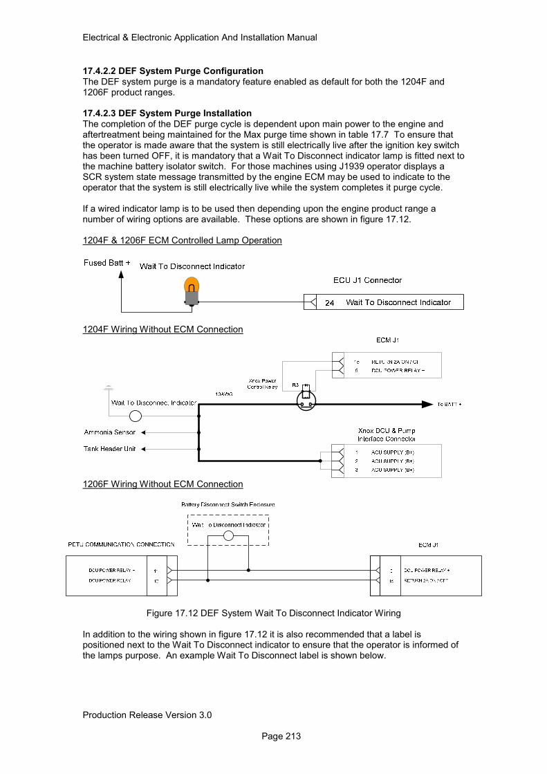
Electrical & Electronic Application And Installation Manual
Production Release Version 3.0 Page 213
17.4.2.2 DEF System Purge Configuration The DEF system purge is a mandatory feature enabled as default for both the 1204F and 1206F product ranges. 17.4.2.3 DEF System Purge Installation The completion of the DEF purge cycle is dependent upon main power to the engine and aftertreatment being maintained for the Max purge time shown in table 17.7 To ensure that the operator is made aware that the system is still electrically live after the ignition key switch has been turned OFF, it is mandatory that a Wait To Disconnect indicator lamp is fitted next to the machine battery isolator switch. For those machines using J1939 operator displays a SCR system state message transmitted by the engine ECM may be used to indicate to the operator that the system is still electrically live while the system completes it purge cycle. If a wired indicator lamp is to be used then depending upon the engine product range a number of wiring options are available. These options are shown in figure 17.12. 1204F & 1206F ECM Controlled Lamp Operation
1204F Wiring Without ECM Connection
1206F Wiring Without ECM Connection
Figure 17.12 DEF System Wait To Disconnect Indicator Wiring
In addition to the wiring shown in figure 17.12 it is also recommended that a label is positioned next to the Wait To Disconnect indicator to ensure that the operator is informed of the lamps purpose. An example Wait To Disconnect label is shown below.
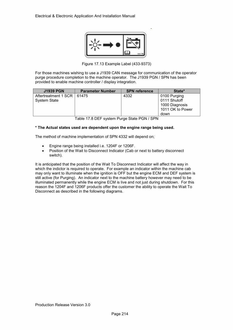
Electrical & Electronic Application And Installation Manual
Production Release Version 3.0 Page 214
Figure 17.13 Example Label (433-9373)
For those machines wishing to use a J1939 CAN message for communication of the operator purge procedure completion to the machine operator. The J1939 PGN / SPN has been provided to enable machine controller / display integration.
J1939 PGN Parameter Number SPN reference State*
Aftertreatment 1 SCR System State
61475 4332 0100 Purging 0111 Shutoff 1000 Diagnosis 1011 OK to Power down
Table 17.8 DEF system Purge State PGN / SPN * The Actual states used are dependent upon the engine range being used. The method of machine implementation of SPN 4332 will depend on;
• Engine range being installed i.e. 1204F or 1206F.
• Position of the Wait to Disconnect Indicator (Cab or next to battery disconnect switch).
It is anticipated that the position of the Wait To Disconnect Indicator will affect the way in which the indictor is required to operate. For example an indicator within the machine cab may only want to illuminate when the ignition is OFF but the engine ECM and DEF system is still active (for Purging). An indicator next to the machine battery however may need to be illuminated permanently while the engine ECM is live and not just during shutdown. For this reason the 1204F and 1206F products offer the customer the ability to operate the Wait To Disconnect as described in the following diagrams.
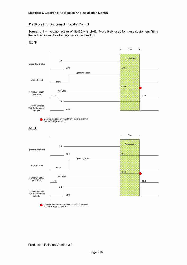
Electrical & Electronic Application And Installation Manual
Production Release Version 3.0 Page 215
J1939 Wait To Disconnect Indicator Control Scenario 1 – Indicator active While ECM is LIVE. Most likely used for those customers fitting the indicator next to a battery disconnect switch. 1204F
Ignition Key Switch
Engine Speed
ECM PGN 61475
SPN 4332
J1939 Controlled
Wait To Disconnect
Indicator
ON
OFF
Tsec
Purge Active
ON
OFF
1111
Any State
0100
1011
OFF
0rpm
Operating Speed
Denotes Indicator active until 1011 state is received
from SPN 4332 on CAN A 1206F
Ignition Key Switch
Engine Speed
ECM PGN 61475
SPN 4332
J1939 Controlled
Wait To Disconnect
Indicator
ON
OFF
Tsec
Purge Active
ON
OFF
1111
Any State
1000
0111
OFF
0rpm
Operating Speed
Denotes Indicator active until 0111 state is received
from SPN 4332 on CAN A
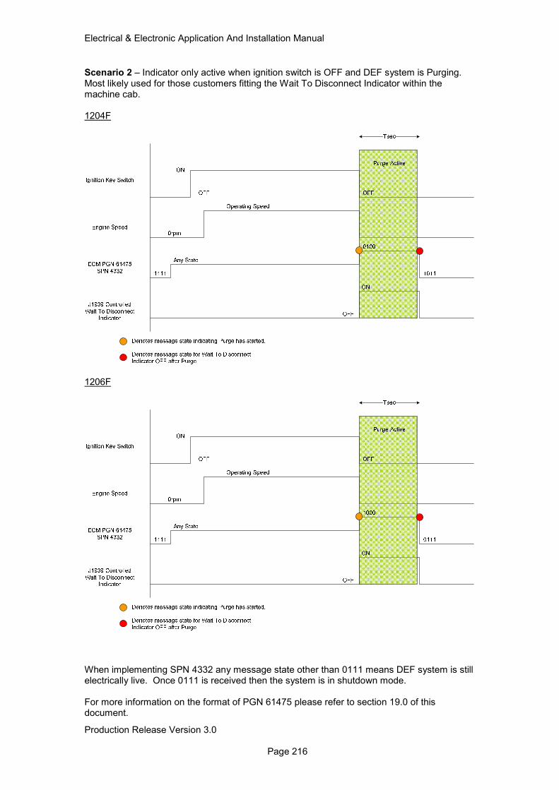
Electrical & Electronic Application And Installation Manual
Production Release Version 3.0 Page 216
Scenario 2 – Indicator only active when ignition switch is OFF and DEF system is Purging. Most likely used for those customers fitting the Wait To Disconnect Indicator within the machine cab. 1204F
1206F
When implementing SPN 4332 any message state other than 0111 means DEF system is still electrically live. Once 0111 is received then the system is in shutdown mode. For more information on the format of PGN 61475 please refer to section 19.0 of this document.
Electrical & Electronic Application And Installation Manual
Production Release Version 3.0 Page 217
17.4.3 DEF Thaw 17.4.3.1 DEF Thaw Operation DEF becomes a solid at temperatures of -11DegC and below. In order for engine out NOx levels to be controlled in cold ambient a DEF system heating or thaw strategy is used. The thaw strategy is an automatic strategy that uses information from various system temperature sensors. The System thaw strategy is an engine running strategy only, using both electrical heating for DEF lines and coolant heating for tank thaw. 17.4.3.2 DEF System Thaw Configuration No configuration is required for the DEF thaw strategy to operate correctly. 17.4.3.3 DEF System Thaw Installation As described in section 4.2 the DEF system requires an electrical current in order for the heating system to operate correctly. These Electrical currents may be required to thaw the system in cold ambient in addition to the current required to run the engine ECM and the machine system. For this reason it is important that an assessment of the engine low idle current demand is made to ensure that the chosen alternator specification can meet the total system demand. All electrical connections required for correct system operation are shown in sections 7, 8 and 9 of this document.
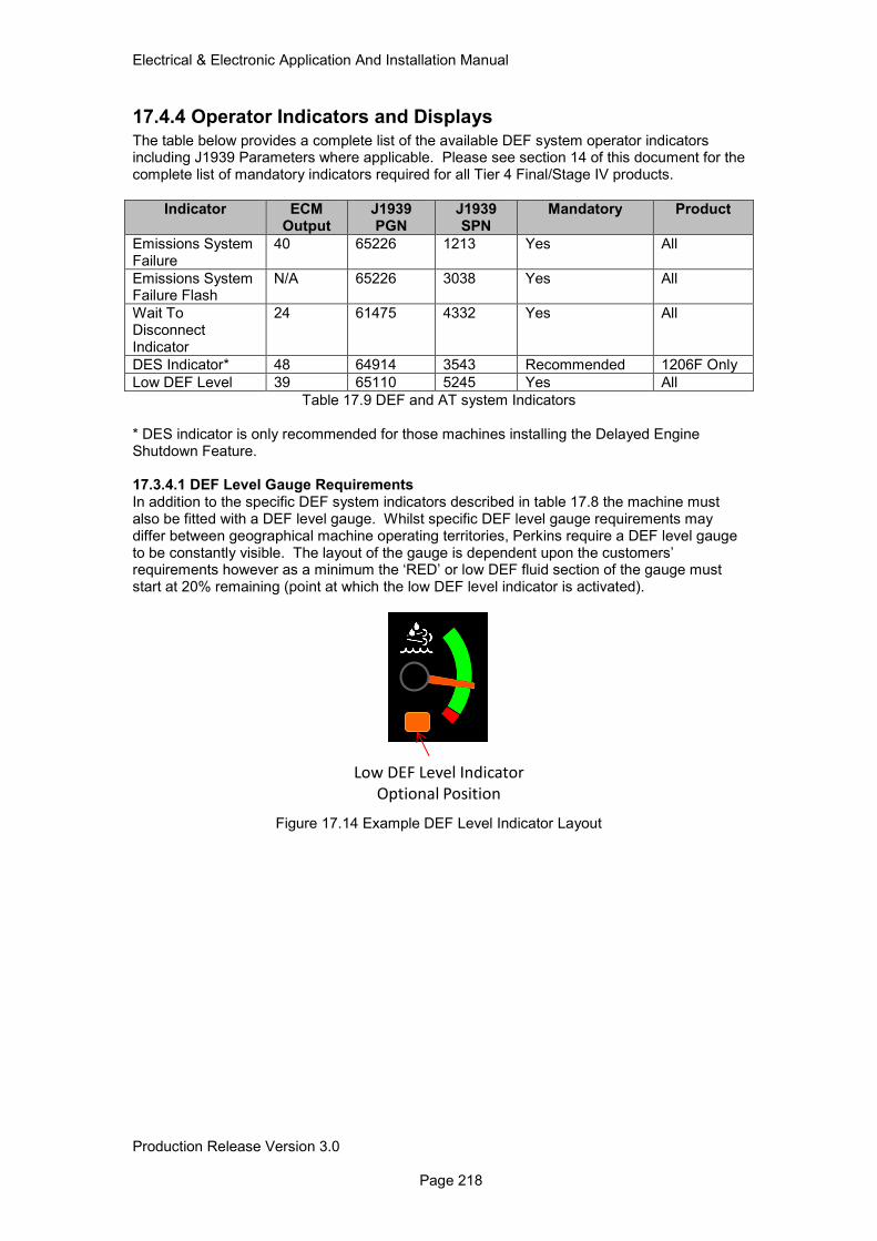
Electrical & Electronic Application And Installation Manual
Production Release Version 3.0 Page 218
17.4.4 Operator Indicators and Displays
The table below provides a complete list of the available DEF system operator indicators including J1939 Parameters where applicable. Please see section 14 of this document for the complete list of mandatory indicators required for all Tier 4 Final/Stage IV products.
Indicator ECM Output
J1939 PGN
J1939 SPN
Mandatory Product
Emissions System Failure
40 65226 1213 Yes All
Emissions System Failure Flash
N/A 65226 3038 Yes All
Wait To Disconnect Indicator
24 61475 4332 Yes All
DES Indicator* 48 64914 3543 Recommended 1206F Only
Low DEF Level 39 65110 5245 Yes All
Table 17.9 DEF and AT system Indicators * DES indicator is only recommended for those machines installing the Delayed Engine Shutdown Feature. 17.3.4.1 DEF Level Gauge Requirements In addition to the specific DEF system indicators described in table 17.8 the machine must also be fitted with a DEF level gauge. Whilst specific DEF level gauge requirements may differ between geographical machine operating territories, Perkins require a DEF level gauge to be constantly visible. The layout of the gauge is dependent upon the customers’ requirements however as a minimum the ‘RED’ or low DEF fluid section of the gauge must start at 20% remaining (point at which the low DEF level indicator is activated).
Low DEF Level Indicator
Optional Position
Figure 17.14 Example DEF Level Indicator Layout
Electrical & Electronic Application And Installation Manual
Production Release Version 3.0 Page 219
18.0 Engine Governor
18.1 Min / Max Governing
18.1.1 Min / Max Governing Operation
The min/max engine speed governor will provide an approximate amount of power for a given throttle position. Engine speed is allowed to vary between the low idle and high idle engine speed settings. This governor essentially only ‘governs’ engine speed when at the minimum or maximum allowed engine speed. In between these limits, the throttle position will cause the engine to produce power proportional to its value. The benefit of this type of governor is smoother shifting for engines with electronic automatic/automated transmissions. The Min/Max governor is also known as the ‘limiting speed’ or ‘power throttle’ governor. The Min/Max engine speed governor control strategy uses the isochronous speed governor to control the engine speed when operating at the minimum (low idle) and maximum (high idle) speeds. This is the same control strategy used by the full range engine speed governor, but with a fixed desired engine speed input of low idle and high idle. The governor control strategy does not try to control fuel delivery and engine speed at the operating speeds between low idle and high idle. The Min/Max engine speed governor will attempt to maintain a constant engine power output based on the throttle position. This design provides optimised shift quality with automatic transmissions and offers excellent power modulation, which allows the operator to adjust the engine power output to match typical vehicle operating conditions. The engine will accelerate or decelerate to ‘find’ a vehicle load level that matches the engine output command by the throttle. If the throttle is commanding more power than the vehicle load will offer, the engine will accelerate to the high idle speed. Machines that are lightly loaded will achieve a desired acceleration at a lower throttle position than machines that are heavily loaded. Machines with very high power/weight ratios will accelerate at very low throttle positions. Figure 18.1 illustrates the Min/Max engine speed governor operation across the engine operating speed range. The curve is bounded by the rating torque curve between LI and Rated engine speed (RS) once above rated speed the HSG limit curve takes over. For a fixed throttle position, the Min/Max governor will deliver a constant amount of power proportional to the throttle position, the engine power output will remain fairly constant, and engine speed will vary with engine load. Min/Max governing above the configured Rated speed (RS) is limited by the HSG limit curve. This region of operation is often referred to as the overrun region (shown in figure 18.1 as the High Speed Governor operating area). The HSG limit curve is always below the rated torque curve. This curve is linear and the slope of the line is determined by the configured Rated speed point (RS) and HI engine speeds (run out line).
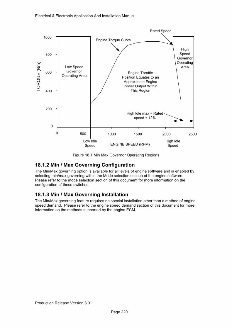
Electrical & Electronic Application And Installation Manual
Production Release Version 3.0 Page 220
Figure 18.1 Min Max Governor Operating Regions
18.1.2 Min / Max Governing Configuration The Min/Max governing option is available for all levels of engine software and is enabled by selecting min/max governing within the Mode selection section of the engine software. Please refer to the mode selection section of this document for more information on the configuration of these switches.
18.1.3 Min / Max Governing Installation The Min/Max governing feature requires no special installation other than a method of engine speed demand. Please refer to the engine speed demand section of this document for more information on the methods supported by the engine ECM.
Low Speed
Governor
Operating Area
High
Speed
Governor
Operating
Area
ENGINE SPEED (RPM)
TO
RQ
UE
(N
m)
0
0
200
500
400
600
800
1000 25001500 2000
Low Idle
Speed
High Idle
Speed
1000
Engine Throttle
Position Equates to an
Approximate Engine
Power Output Within
This Region
Engine Torque Curve
High Idle max = Rated
speed + 12%
Rated Speed
Electrical & Electronic Application And Installation Manual
Production Release Version 3.0 Page 221
18.2 Engine All Speed Governing The default governor type is an All Speed Governor, also known as a variable Speed Governor. The diagrams and text below in figures 18.2 and 18.3 illustrate the torque and speed characteristics of this governor.
18.2.1 Engine All Speed Governing Operation The All Speed Engine Governor will attempt to hold a constant engine speed for a given throttle position. The governor senses engine speed and load and meters the fuel supply to the engine such that the engine speed remains constant or to vary with the load in a predetermined manner. This governor type is recommended for use on applications with a constant operating speed and applications with manual transmissions. The all speed governor is also known as ‘variable speed’ or ‘full range engine speed governor’ The governor strategy calculates the fuel quantity required to keep the actual engine speed equal to the desired engine speed. The desired engine speed is the output of the throttle arbitration strategy defined in the Engine speed demand section 12.0 of this document. All speed refers to the fact that the engine governor operates across the full engine speed operating range. The governor strategy has control parameters classed as governor gains, which determine the engine response and engine stability. These gains are ‘tuned’ to ensure that they are configured for optimum performance under both steady state and transient conditions. Under default conditions the engine is set to operate with isochronous governing across the engine speed range, during which the engine fuelling is bound by the engine torque curve. Note that the engine may not be capable of reaching the torque fuel limit curve in some circumstances. For example, if the turbocharger is not providing the required boost pressure, then the fuel will be limited so that the engine does not emit black smoke. Engines can however be configured to operate with a level of engine droop, under the torque curve. Droop is the variation of engine speed as load is applied. For example, if an engine has 10% droop and is running at 1500RPM without load, then as load is applied the operator will feel and hear the engine speed gradually decreasing. This is represented by the diagonal dotted lines under the torque curve in the diagram below. When the load reaches the torque limit curve of the engine, the engine will lug back along the curve. Note that droop values can be assigned to the multi-position throttle switch input, PWM accelerator pedal/lever input and the TSC1 speed demand over J1939. Droop does not apply, however to the PTO mode, which always operates isochronously (0% Droop) The high speed governor (governor run-out) is governed by the relationship between the rated engine speed (this is fixed for each rating and cannot be altered) and the chosen high idle speed. High Idle is the maximum speed that the engine will reach. Note that this is on the bare engine and when installed in an application, it may not be possible to reach this speed due to the parasitic loads of the driven equipment. The range of possible high idle speeds is defined by the parameters, High Idle Lower limit (HILL) and High Idle Upper Limit. (HIUL). High Idle cannot be specified to be less than Rated Speed (RS) and cannot exceed RS+12%. This HIUL is specified to ensure governor stability is maintained throughout the engine operating range. Example Governing1 - showing droop and HSG slopes approximately equal.
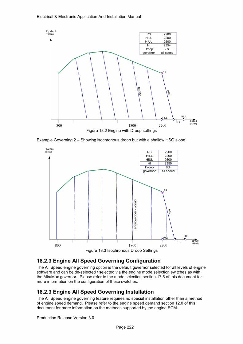
Electrical & Electronic Application And Installation Manual
Production Release Version 3.0 Page 222
800 1800 2200
RS
HS
G
DR
OO
P
Flywheel
Torque
Speed
(RPM)
HILL
HIUL
2200
2600
7%Droop
2200RS
2354HI
all speedgovernor
HI
HIULHILL
Figure 18.2 Engine with Droop settings
Example Governing 2 – Showing isochronous droop but with a shallow HSG slope.
800 1800 2200
RS
HS
G
DR
OO
P =
ISO
CH
RO
NO
US
Flywheel
Torque
Speed
(RPM)
HILL
HIUL
2200
2600
0%Droop
2200RS
2350HI
all speedgovernor
HI
HIULHILL
Figure 18.3 Isochronous Droop Settings
18.2.3 Engine All Speed Governing Configuration
The All Speed engine governing option is the default governor selected for all levels of engine software and can be de-selected / selected via the engine mode selection switches as with the Min/Max governor. Please refer to the mode selection section 17.5 of this document for more information on the configuration of these switches.
18.2.3 Engine All Speed Governing Installation The All Speed engine governing feature requires no special installation other than a method of engine speed demand. Please refer to the engine speed demand section 12.0 of this document for more information on the methods supported by the engine ECM.
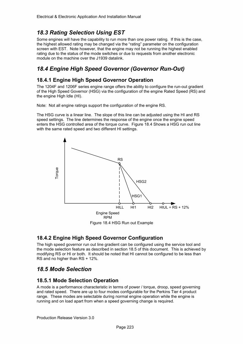
Electrical & Electronic Application And Installation Manual
Production Release Version 3.0 Page 223
18.3 Rating Selection Using EST Some engines will have the capability to run more than one power rating. If this is the case, the highest allowed rating may be changed via the “rating” parameter on the configuration screen with EST. Note however, that the engine may not be running the highest enabled rating due to the status of the mode switches or due to requests from another electronic module on the machine over the J1939 datalink.
18.4 Engine High Speed Governor (Governor Run-Out)
18.4.1 Engine High Speed Governor Operation
The 1204F and 1206F series engine range offers the ability to configure the run-out gradient of the High Speed Governor (HSG) via the configuration of the engine Rated Speed (RS) and the engine High Idle (HI). Note: Not all engine ratings support the configuration of the engine RS. The HSG curve is a linear line. The slope of this line can be adjusted using the HI and RS speed settings. The line determines the response of the engine once the engine speed enters the HSG controlled area of the torque curve. Figure 18.4 Shows a HSG run out line with the same rated speed and two different HI settings.
Figure 18.4 HSG Run out Example
18.4.2 Engine High Speed Governor Configuration The high speed governor run out line gradient can be configured using the service tool and the mode selection feature as described in section 18.5 of this document. This is achieved by modifying RS or HI or both. It should be noted that HI cannot be configured to be less than RS and no higher than RS + 12%.
18.5 Mode Selection
18.5.1 Mode Selection Operation A mode is a performance characteristic in terms of power / torque, droop, speed governing and rated speed. There are up to four modes configurable for the Perkins Tier 4 product range. These modes are selectable during normal engine operation while the engine is running and on load apart from when a speed governing change is required.
RS
HILL HI1 HI2
HSG2
HSG1
HIUL = RS + 12%
Torq
ue
Engine Speed
RPM
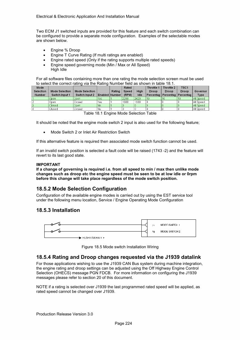
Electrical & Electronic Application And Installation Manual
Production Release Version 3.0 Page 224
Two ECM J1 switched inputs are provided for this feature and each switch combination can be configured to provide a separate mode configuration. Examples of the selectable modes are shown below.
• Engine % Droop
• Engine T Curve Rating (If multi ratings are enabled)
• Engine rated speed (Only if the rating supports multiple rated speeds)
• Engine speed governing mode (Min / Max or All Speed) High Idle For all software files containing more than one rating the mode selection screen must be used to select the correct rating via the Rating Number field as shown in table 18.1.
Table 18.1 Engine Mode Selection Table
It should be noted that the engine mode switch 2 input is also used for the following feature;
• Mode Switch 2 or Inlet Air Restriction Switch If this alternative feature is required then associated mode switch function cannot be used. If an invalid switch position is selected a fault code will be raised (1743 -2) and the feature will revert to its last good state. IMPORTANT If a change of governing is required i.e. from all speed to min / max then unlike mode changes such as droop etc the engine speed must be seen to be at low idle or 0rpm before this change will take place regardless of the mode switch position.
18.5.2 Mode Selection Configuration
Configuration of the available engine modes is carried out by using the EST service tool under the following menu location, Service / Engine Operating Mode Configuration
18.5.3 Installation
Figure 18.5 Mode switch Installation Wiring
18.5.4 Rating and Droop changes requested via the J1939 datalink For those applications wishing to use the J1939 CAN Bus system during machine integration, the engine rating and droop settings can be adjusted using the Off Highway Engine Control Selection (OHECS) message PGN FDCB. For more information on configuring the J1939 messages please refer to section 20 of this document. NOTE if a rating is selected over J1939 the last programmed rated speed will be applied, as rated speed cannot be changed over J1939.
Electrical & Electronic Application And Installation Manual
Production Release Version 3.0 Page 225
19.0 Datalink Support Both the 1200 series Tier 4 Final/Stage IV product range is supplied with a customer J1939 CAN bus connection as part of the ECM J1 connector. The J1939 standard is a widely used protocol, which operates on a standard CANBus system. All J1939 enabled devices will operate on this datalink and the remainder of this section details the basic requirements for J1939 communication. The Perkins datalink is a proprietary datalink, which can be used with specialist devices available through Perkins aftermarket networks. It should be noted that these are currently the only two datalinks supported by the ECM hardware and the incorporation of the engine into systems operating on protocols such as ModBus will require a gateway to convert the protocol to J1939 for ECM communication.
19.1 SAE J1939 The SAE standard was initially developed for the US truck and bus industry. It has been expanded and is now the most widely used datalink standard for industrial power trains, with compliance from almost all engine and transmission manufacturers. A list of SAE J1939 documentation, which should be used as reference when installing a J1939 network, are listed below. SAE J1939-11 Physical Layer, 250Kbits/s, Twisted Shielded pair. SAE J1939-15 Reduced Physical Layer, 250Kbits/s, Un-shielded Twisted pair. SAE J1939-21 Data Link Layer. SAE J1939-31 Network Layer. SAE J1939-71 Vehicle Application Layer. SAE J1939-73 Application Layer Diagnostics.
19.1.1 Summary of Key J1939 Application Issues
This is a summary of some of the key points and answers to frequently asked questions relating to design of a J1939 compatible network. It is intended to give a design overview and does not in any way replace or contradict the recommendations or design criteria contained within the SAE J1939 standard documents.
19.1.2 Physical layer
• The data rate is 250Kbits/sec
• Twisted pair cable, of a 120Ohm impedance characteristic, should be used throughout. Note that most commercially available twisted pair cable is not suitable.
• It is recommend that this cable is shielded (as per J1939-11) and that the screen is grounded at a central point in the network. Unshielded twisted pair cable is used by some machine manufacturers, however (as per J1939-15), offering lower cost but lower immunity to electromagnetic noise.
• The bus is linear and should be terminated with 120Ohm resistors at either end. It is a common mistake to use one 60Ohm resistor instead of two 120Ohm resistors. This does not work correctly however.
• Maximum bus length is 40m.
• The terminating resistors should not be contained in network nodes.
• Network nodes are connected to the bus via stubs of maximum recommended length 1m.
19.1.3 Network Layer
• J1939 recommends a bit sample point of 87 percent. This relatively late sampling point, which gives the best immunity to noise and propagation delay. It does restrict the size of the software jump width (SJW), however.
• All nodes must have the same bit timing.
• Accurate bit timing is essential (4ms +/- 0.2 percent).
• It is recommended that the average busload is not greater than 40 percent.
Electrical & Electronic Application And Installation Manual
Production Release Version 3.0 Page 226
• Hardware filtering (masking) of CAN messages should be used under high busload limit demands on processors.
• The engine ECM always assumes a fixed address zero. It will not change its address in the arbitration process described in J1939-81.
• The multi 7 packet protocol (described in J1939-21) is used for sending messages with more than eight bytes of data. In the machine application this will be used principally for the diagnostic messages DM1 and DM2.
• Information may be broadcast or requested at regular intervals. For example, the engine will broadcast its ‘current speed’ every 20ms but it will only send ‘hours run’ information if another node requests it.
19.1.4 Application Layer
• The messages (PGN’s) supported by the engine ECM are only a subset of the messages described in J1939-71 and J1939-73.
• Some PGN’s maybe partially supported i.e. only those bytes for which the ECM has valid data will be supported.
• Unsupported data bytes are generally sent as FF (hex) and incorrect or invalid information is sent as FE.
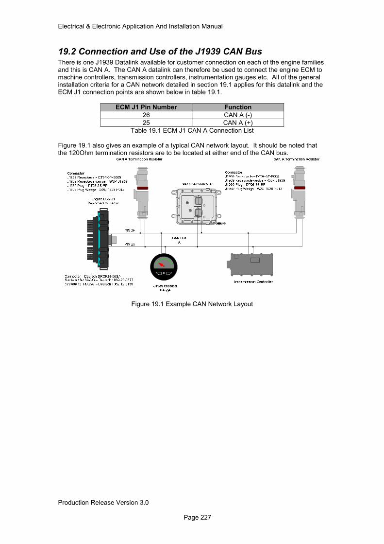
Electrical & Electronic Application And Installation Manual
Production Release Version 3.0 Page 227
19.2 Connection and Use of the J1939 CAN Bus There is one J1939 Datalink available for customer connection on each of the engine families and this is CAN A. The CAN A datalink can therefore be used to connect the engine ECM to machine controllers, transmission controllers, instrumentation gauges etc. All of the general installation criteria for a CAN network detailed in section 19.1 applies for this datalink and the ECM J1 connection points are shown below in table 19.1.
ECM J1 Pin Number Function
26 CAN A (-)
25 CAN A (+)
Table 19.1 ECM J1 CAN A Connection List Figure 19.1 also gives an example of a typical CAN network layout. It should be noted that the 120Ohm termination resistors are to be located at either end of the CAN bus.
Figure 19.1 Example CAN Network Layout
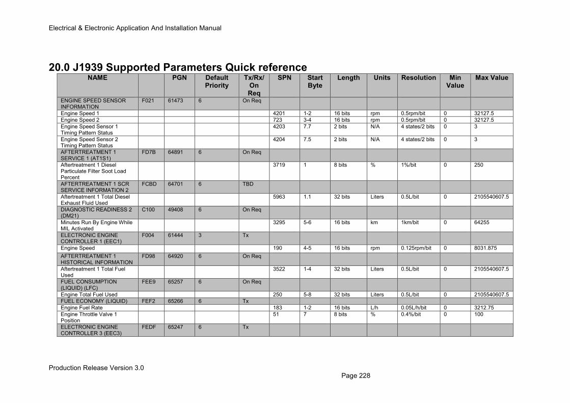
Electrical & Electronic Application And Installation Manual
Production Release Version 3.0 Page 228
20.0 J1939 Supported Parameters Quick reference NAME PGN Default
Priority Tx/Rx/
On Req
SPN Start Byte
Length Units Resolution Min Value
Max Value
ENGINE SPEED SENSOR INFORMATION
F021
61473 6 On Req
Engine Speed 1 4201 1-2 16 bits rpm 0.5rpm/bit 0 32127.5
Engine Speed 2 723 3-4 16 bits rpm 0.5rpm/bit 0 32127.5
Engine Speed Sensor 1 Timing Pattern Status
4203 7.7 2 bits N/A 4 states/2 bits 0 3
Engine Speed Sensor 2 Timing Pattern Status
4204 7.5 2 bits N/A 4 states/2 bits 0 3
AFTERTREATMENT 1 SERVICE 1 (AT1S1)
FD7B 64891 6 On Req
Aftertreatment 1 Diesel Particulate Filter Soot Load Percent
3719 1 8 bits % 1%/bit 0 250
AFTERTREATMENT 1 SCR SERVICE INFORMATION 2
FCBD 64701 6 TBD
Aftertreatment 1 Total Diesel Exhaust Fluid Used
5963 1.1 32 bits Liters 0.5L/bit 0 2105540607.5
DIAGNOSTIC READINESS 2 (DM21)
C100 49408 6 On Req
Minutes Run By Engine While MIL Activated
3295 5-6 16 bits km 1km/bit 0 64255
ELECTRONIC ENGINE CONTROLLER 1 (EEC1)
F004 61444 3 Tx
Engine Speed 190 4-5 16 bits rpm 0.125rpm/bit 0 8031.875
AFTERTREATMENT 1 HISTORICAL INFORMATION
FD98
64920 6 On Req
Aftertreatment 1 Total Fuel Used
3522 1-4 32 bits Liters 0.5L/bit 0 2105540607.5
FUEL CONSUMPTION (LIQUID) (LFC)
FEE9 65257 6 On Req
Engine Total Fuel Used 250 5-8 32 bits Liters 0.5L/bit 0 2105540607.5
FUEL ECONOMY (LIQUID) FEF2 65266 6 Tx
Engine Fuel Rate 183 1-2 16 bits L/h 0.05L/h/bit 0 3212.75
Engine Throttle Valve 1 Position
51 7 8 bits % 0.4%/bit 0 100
ELECTRONIC ENGINE CONTROLLER 3 (EEC3)
FEDF 65247 6 Tx
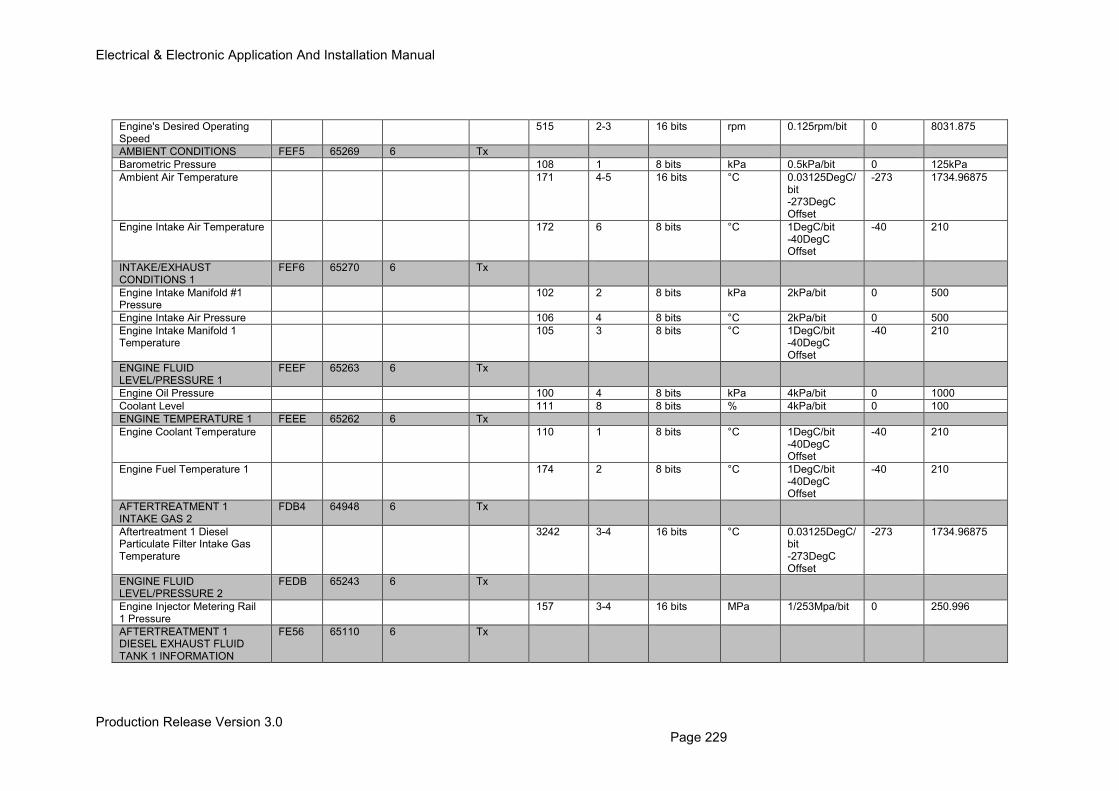
Electrical & Electronic Application And Installation Manual
Production Release Version 3.0 Page 229
Engine's Desired Operating Speed
515 2-3 16 bits rpm 0.125rpm/bit 0 8031.875
AMBIENT CONDITIONS FEF5 65269 6 Tx
Barometric Pressure 108 1 8 bits kPa 0.5kPa/bit 0 125kPa
Ambient Air Temperature 171 4-5 16 bits °C 0.03125DegC/bit -273DegC Offset
-273 1734.96875
Engine Intake Air Temperature 172 6 8 bits °C 1DegC/bit -40DegC Offset
-40 210
INTAKE/EXHAUST CONDITIONS 1
FEF6 65270 6 Tx
Engine Intake Manifold #1 Pressure
102 2 8 bits kPa 2kPa/bit 0 500
Engine Intake Air Pressure 106 4 8 bits °C 2kPa/bit 0 500
Engine Intake Manifold 1 Temperature
105 3 8 bits °C 1DegC/bit -40DegC Offset
-40 210
ENGINE FLUID LEVEL/PRESSURE 1
FEEF 65263 6 Tx
Engine Oil Pressure 100 4 8 bits kPa 4kPa/bit 0 1000
Coolant Level 111 8 8 bits % 4kPa/bit 0 100
ENGINE TEMPERATURE 1 FEEE 65262 6 Tx
Engine Coolant Temperature 110 1 8 bits °C 1DegC/bit -40DegC Offset
-40 210
Engine Fuel Temperature 1 174 2 8 bits °C 1DegC/bit -40DegC Offset
-40 210
AFTERTREATMENT 1 INTAKE GAS 2
FDB4 64948 6 Tx
Aftertreatment 1 Diesel Particulate Filter Intake Gas Temperature
3242 3-4 16 bits °C 0.03125DegC/bit -273DegC Offset
-273 1734.96875
ENGINE FLUID LEVEL/PRESSURE 2
FEDB 65243 6 Tx
Engine Injector Metering Rail 1 Pressure
157 3-4 16 bits MPa 1/253Mpa/bit 0 250.996
AFTERTREATMENT 1 DIESEL EXHAUST FLUID TANK 1 INFORMATION
FE56 65110 6 Tx
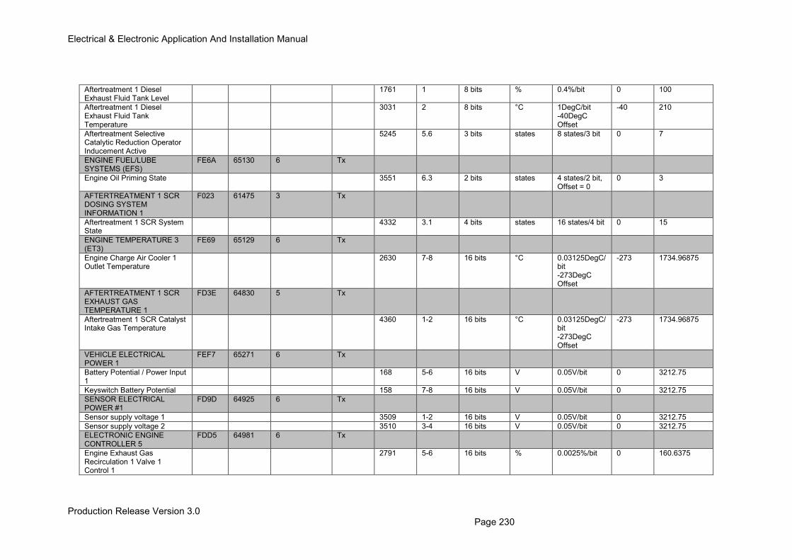
Electrical & Electronic Application And Installation Manual
Production Release Version 3.0 Page 230
Aftertreatment 1 Diesel Exhaust Fluid Tank Level
1761 1 8 bits % 0.4%/bit 0 100
Aftertreatment 1 Diesel Exhaust Fluid Tank Temperature
3031 2 8 bits °C 1DegC/bit -40DegC Offset
-40 210
Aftertreatment Selective Catalytic Reduction Operator Inducement Active
5245 5.6 3 bits states 8 states/3 bit 0 7
ENGINE FUEL/LUBE SYSTEMS (EFS)
FE6A 65130 6 Tx
Engine Oil Priming State 3551 6.3 2 bits states 4 states/2 bit, Offset = 0
0 3
AFTERTREATMENT 1 SCR DOSING SYSTEM INFORMATION 1
F023 61475 3 Tx
Aftertreatment 1 SCR System State
4332 3.1 4 bits states 16 states/4 bit 0 15
ENGINE TEMPERATURE 3 (ET3)
FE69 65129 6 Tx
Engine Charge Air Cooler 1 Outlet Temperature
2630 7-8 16 bits °C 0.03125DegC/bit -273DegC Offset
-273 1734.96875
AFTERTREATMENT 1 SCR EXHAUST GAS TEMPERATURE 1
FD3E
64830 5 Tx
Aftertreatment 1 SCR Catalyst Intake Gas Temperature
4360 1-2 16 bits °C 0.03125DegC/bit -273DegC Offset
-273 1734.96875
VEHICLE ELECTRICAL POWER 1
FEF7 65271 6 Tx
Battery Potential / Power Input 1
168 5-6 16 bits V 0.05V/bit 0 3212.75
Keyswitch Battery Potential 158 7-8 16 bits V 0.05V/bit 0 3212.75
SENSOR ELECTRICAL POWER #1
FD9D 64925 6 Tx
Sensor supply voltage 1 3509 1-2 16 bits V 0.05V/bit 0 3212.75
Sensor supply voltage 2 3510 3-4 16 bits V 0.05V/bit 0 3212.75
ELECTRONIC ENGINE CONTROLLER 5
FDD5 64981 6 Tx
Engine Exhaust Gas Recirculation 1 Valve 1 Control 1
2791 5-6 16 bits % 0.0025%/bit 0 160.6375
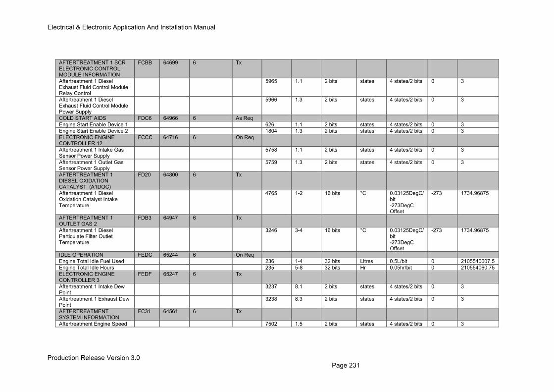
Electrical & Electronic Application And Installation Manual
Production Release Version 3.0 Page 231
AFTERTREATMENT 1 SCR ELECTRONIC CONTROL MODULE INFORMATION
FCBB
64699 6 Tx
Aftertreatment 1 Diesel Exhaust Fluid Control Module Relay Control
5965 1.1 2 bits states 4 states/2 bits 0 3
Aftertreatment 1 Diesel Exhaust Fluid Control Module Power Supply
5966 1.3 2 bits states 4 states/2 bits 0 3
COLD START AIDS FDC6 64966 6 As Req
Engine Start Enable Device 1 626 1.1 2 bits states 4 states/2 bits 0 3
Engine Start Enable Device 2 1804 1.3 2 bits states 4 states/2 bits 0 3
ELECTRONIC ENGINE CONTROLLER 12
FCCC 64716 6 On Req
Aftertreatment 1 Intake Gas Sensor Power Supply
5758 1.1 2 bits states 4 states/2 bits 0 3
Aftertreatment 1 Outlet Gas Sensor Power Supply
5759 1.3 2 bits states 4 states/2 bits 0 3
AFTERTREATMENT 1 DIESEL OXIDATION CATALYST (A1DOC)
FD20 64800 6 Tx
Aftertreatment 1 Diesel Oxidation Catalyst Intake Temperature
4765 1-2 16 bits °C 0.03125DegC/bit -273DegC Offset
-273 1734.96875
AFTERTREATMENT 1 OUTLET GAS 2
FDB3 64947 6 Tx
Aftertreatment 1 Diesel Particulate Filter Outlet Temperature
3246 3-4 16 bits °C 0.03125DegC/bit -273DegC Offset
-273 1734.96875
IDLE OPERATION FEDC 65244 6 On Req
Engine Total Idle Fuel Used 236 1-4 32 bits Litres 0.5L/bit 0 2105540607.5
Engine Total Idle Hours 235 5-8 32 bits Hr 0.05hr/bit 0 210554060.75
ELECTRONIC ENGINE CONTROLLER 3
FEDF 65247 6 Tx
Aftertreatment 1 Intake Dew Point
3237 8.1 2 bits states 4 states/2 bits 0 3
Aftertreatment 1 Exhaust Dew Point
3238 8.3 2 bits states 4 states/2 bits 0 3
AFTERTREATMENT SYSTEM INFORMATION
FC31 64561 6 Tx
Aftertreatment Engine Speed 7502 1.5 2 bits states 4 states/2 bits 0 3
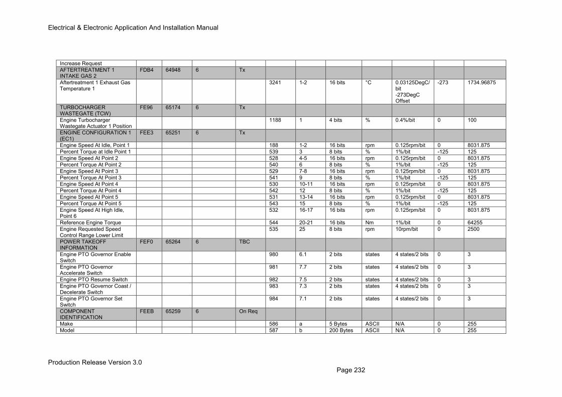
Electrical & Electronic Application And Installation Manual
Production Release Version 3.0 Page 232
Increase Request
AFTERTREATMENT 1 INTAKE GAS 2
FDB4 64948 6 Tx
Aftertreatment 1 Exhaust Gas Temperature 1
3241 1-2 16 bits °C 0.03125DegC/bit -273DegC Offset
-273 1734.96875
TURBOCHARGER WASTEGATE (TCW)
FE96 65174 6 Tx
Engine Turbocharger Wastegate Actuator 1 Position
1188 1 4 bits % 0.4%/bit 0 100
ENGINE CONFIGURATION 1 (EC1)
FEE3 65251 6 Tx
Engine Speed At Idle, Point 1 188 1-2 16 bits rpm 0.125rpm/bit 0 8031.875
Percent Torque at Idle Point 1 539 3 8 bits % 1%/bit -125 125
Engine Speed At Point 2 528 4-5 16 bits rpm 0.125rpm/bit 0 8031.875
Percent Torque At Point 2 540 6 8 bits % 1%/bit -125 125
Engine Speed At Point 3 529 7-8 16 bits rpm 0.125rpm/bit 0 8031.875
Percent Torque At Point 3 541 9 8 bits % 1%/bit -125 125
Engine Speed At Point 4 530 10-11 16 bits rpm 0.125rpm/bit 0 8031.875
Percent Torque At Point 4 542 12 8 bits % 1%/bit -125 125
Engine Speed At Point 5 531 13-14 16 bits rpm 0.125rpm/bit 0 8031.875
Percent Torque At Point 5 543 15 8 bits % 1%/bit -125 125
Engine Speed At High Idle, Point 6
532 16-17 16 bits rpm 0.125rpm/bit 0 8031.875
Reference Engine Torque 544 20-21 16 bits Nm 1%/bit 0 64255
Engine Requested Speed Control Range Lower Limit
535 25 8 bits rpm 10rpm/bit 0 2500
POWER TAKEOFF INFORMATION
FEF0 65264 6 TBC
Engine PTO Governor Enable Switch
980 6.1 2 bits states 4 states/2 bits 0 3
Engine PTO Governor Accelerate Switch
981 7.7 2 bits states 4 states/2 bits 0 3
Engine PTO Resume Switch 982 7.5 2 bits states 4 states/2 bits 0 3
Engine PTO Governor Coast / Decelerate Switch
983 7.3 2 bits states 4 states/2 bits 0 3
Engine PTO Governor Set Switch
984 7.1 2 bits states 4 states/2 bits 0 3
COMPONENT IDENTIFICATION
FEEB 65259 6 On Req
Make 586 a 5 Bytes ASCII N/A 0 255
Model 587 b 200 Bytes ASCII N/A 0 255
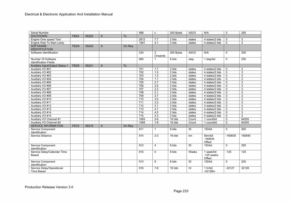
Electrical & Electronic Application And Installation Manual
Production Release Version 3.0 Page 233
Serial Number 588 c 200 Bytes ASCII N/A 0 255
SHUTDOWN FEE4 65252 6 Tx
Engine Over speed Test 2812 7.7 2 bits states 4 states/2 bits 0 3
Engine Wait To Start Lamp 1081 4.1 2 bits states 4 states/2 bits 0 3
SOFTWARE IDENTIFICATION
FEDA 65242 6 On Req
Software Identification 234 2 Onwards
200 Bytes ASCII N/A 0 255
Number Of Software Identification Fields
965 1 8 bits step 1 step/bit 0 250
Auxiliary Input/Output Status 1 FED9 65241 6 Tx
Auxiliary I/O #01 701 1.7 2 bits states 4 states/2 bits 0 3
Auxiliary I/O #02 702 1.5 2 bits states 4 states/2 bits 0 3
Auxiliary I/O #03 703 1.3 2 bits states 4 states/2 bits 0 3
Auxiliary I/O #04 704 1.1 2 bits states 4 states/2 bits 0 3
Auxiliary I/O #05 705 2.7 2 bits states 4 states/2 bits 0 3
Auxiliary I/O #06 706 2.5 2 bits states 4 states/2 bits 0 3
Auxiliary I/O #07 707 2.3 2 bits states 4 states/2 bits 0 3
Auxiliary I/O #08 708 2.1 2 bits states 4 states/2 bits 0 3
Auxiliary I/O #09 709 3.7 2 bits states 4 states/2 bits 0 3
Auxiliary I/O #10 710 3.5 2 bits states 4 states/2 bits 0 3
Auxiliary I/O #11 711 3.3 2 bits states 4 states/2 bits 0 3
Auxiliary I/O #12 712 3.1 2 bits states 4 states/2 bits 0 3
Auxiliary I/O #13 713 4.7 2 bits states 4 states/2 bits 0 3
Auxiliary I/O #14 714 4.5 2 bits states 4 states/2 bits 0 3
Auxiliary I/O #15 715 4.3 2 bits states 4 states/2 bits 0 3
Auxiliary I/O Channel #1 1083 5-6 16 bits Count 1 count/bit 0 64255
Auxiliary I/O Channel #2 1084 7-8 16 bits Count 1 count/bit 0 64255
SERVICE INFORMATION FEC0 65216 6 On Req
Service Component Identification
911 1 8 bits ID 1ID/bit 0 255
Service Distance 914 2-3 16 bits km 5km/bit -160635 Offset
-160635 160640
Service Component Identification
912 4 8 bits ID 1ID/bit 0 255
Service Delay/Calendar Time Based
915 5 8 bits Weeks 1 week/bit -125 weeks Offset
-125 125
Service Component Identification
913 6 8 bits ID 1ID/bit 0 255
Service Delay/Operational Time Based
916 7-8 16 bits Hr 1 hr/bit -32128hr
-32127 32128
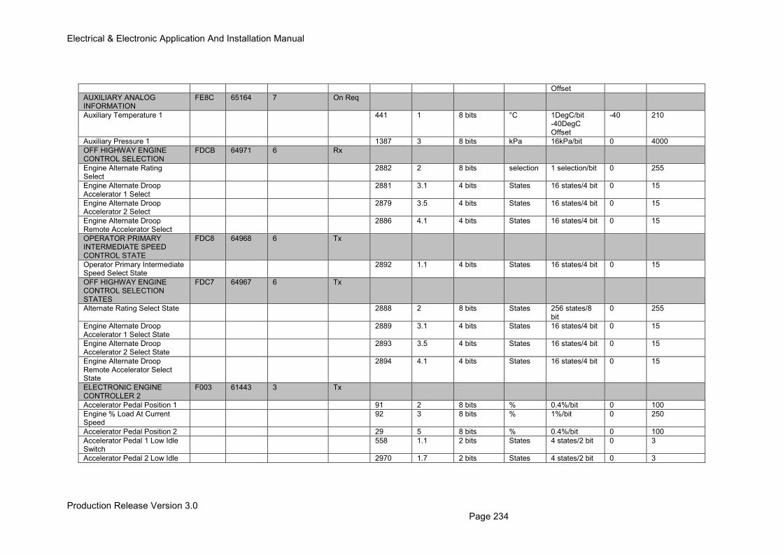
Electrical & Electronic Application And Installation Manual
Production Release Version 3.0 Page 234
Offset
AUXILIARY ANALOG INFORMATION
FE8C 65164 7 On Req
Auxiliary Temperature 1 441 1 8 bits °C 1DegC/bit -40DegC Offset
-40 210
Auxiliary Pressure 1 1387 3 8 bits kPa 16kPa/bit 0 4000
OFF HIGHWAY ENGINE CONTROL SELECTION
FDCB 64971 6 Rx
Engine Alternate Rating Select
2882 2 8 bits selection 1 selection/bit 0 255
Engine Alternate Droop Accelerator 1 Select
2881 3.1 4 bits States 16 states/4 bit 0 15
Engine Alternate Droop Accelerator 2 Select
2879 3.5 4 bits States 16 states/4 bit 0 15
Engine Alternate Droop Remote Accelerator Select
2886 4.1 4 bits States 16 states/4 bit 0 15
OPERATOR PRIMARY INTERMEDIATE SPEED CONTROL STATE
FDC8 64968 6 Tx
Operator Primary Intermediate Speed Select State
2892 1.1 4 bits States 16 states/4 bit 0 15
OFF HIGHWAY ENGINE CONTROL SELECTION STATES
FDC7 64967 6 Tx
Alternate Rating Select State 2888 2 8 bits States 256 states/8 bit
0 255
Engine Alternate Droop Accelerator 1 Select State
2889 3.1 4 bits States 16 states/4 bit 0 15
Engine Alternate Droop Accelerator 2 Select State
2893 3.5 4 bits States 16 states/4 bit 0 15
Engine Alternate Droop Remote Accelerator Select State
2894 4.1 4 bits States 16 states/4 bit 0 15
ELECTRONIC ENGINE CONTROLLER 2
F003 61443 3 Tx
Accelerator Pedal Position 1 91 2 8 bits % 0.4%/bit 0 100
Engine % Load At Current Speed
92 3 8 bits % 1%/bit 0 250
Accelerator Pedal Position 2 29 5 8 bits % 0.4%/bit 0 100
Accelerator Pedal 1 Low Idle Switch
558 1.1 2 bits States 4 states/2 bit 0 3
Accelerator Pedal 2 Low Idle 2970 1.7 2 bits States 4 states/2 bit 0 3
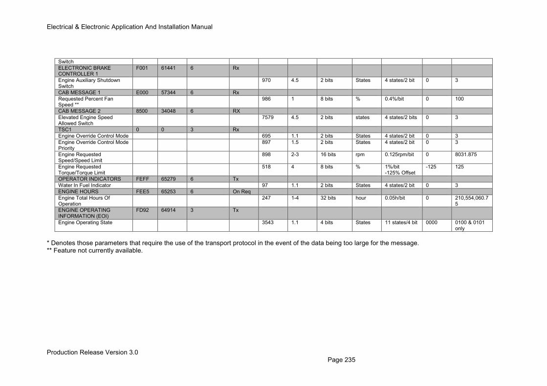
Electrical & Electronic Application And Installation Manual
Production Release Version 3.0 Page 235
Switch
ELECTRONIC BRAKE CONTROLLER 1
F001 61441 6 Rx
Engine Auxiliary Shutdown Switch
970 4.5 2 bits States 4 states/2 bit 0 3
CAB MESSAGE 1 E000 57344 6 Rx
Requested Percent Fan Speed **
986 1 8 bits % 0.4%/bit 0 100
CAB MESSAGE 2 8500 34048 6 RX
Elevated Engine Speed Allowed Switch
7579 4.5 2 bits states 4 states/2 bits 0 3
TSC1 0 0 3 Rx
Engine Override Control Mode 695 1.1 2 bits States 4 states/2 bit 0 3
Engine Override Control Mode Priority
897 1.5 2 bits States 4 states/2 bit 0 3
Engine Requested Speed/Speed Limit
898 2-3 16 bits rpm 0.125rpm/bit 0 8031.875
Engine Requested Torque/Torque Limit
518 4 8 bits % 1%/bit -125% Offset
-125 125
OPERATOR INDICATORS FEFF 65279 6 Tx
Water In Fuel Indicator 97 1.1 2 bits States 4 states/2 bit 0 3
ENGINE HOURS FEE5 65253 6 On Req
Engine Total Hours Of Operation
247 1-4 32 bits hour 0.05h/bit 0 210,554,060.75
ENGINE OPERATING INFORMATION (EOI)
FD92 64914 3 Tx
Engine Operating State 3543 1.1 4 bits States 11 states/4 bit 0000 0100 & 0101 only
* Denotes those parameters that require the use of the transport protocol in the event of the data being too large for the message. ** Feature not currently available.
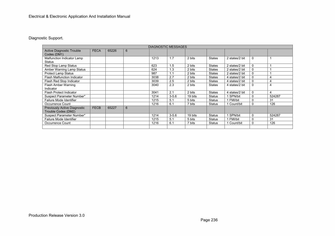
Electrical & Electronic Application And Installation Manual
Production Release Version 3.0 Page 236
Diagnostic Support.
DIAGNOSTIC MESSAGES
Active Diagnostic Trouble Codes (DM1)
FECA 65226 6
Malfunction Indicator Lamp Status
1213 1.7 2 bits States 2 states/2 bit 0 1
Red Stop Lamp Status 623 1.5 2 bits States 2 states/2 bit 0 1
Amber Warning Lamp Status 624 1.3 2 bits States 2 states/2 bit 0 1
Protect Lamp Status 987 1.1 2 bits States 2 states/2 bit 0 1
Flash Malfunction Indicator 3038 2.7 2 bits States 4 states/2 bit 0 4
Flash Red Stop Indicator 3039 2.5 2 bits States 4 states/2 bit 0 4
Flash Amber Warning Indicator
3040 2.3 2 bits States 4 states/2 bit 0 4
Flash Protect Indicator 3041 2.1 2 bits States 4 states/2 bit 0 4
Suspect Parameter Number* 1214 3-5.6 19 bits Status 1 SPN/bit 0 524287
Failure Mode Identifier 1215 5.1 5 bits Status 1 FMI/bit 0 31
Occurrence Count 1216 6.1 7 bits Status 1 Count/bit 0 126
Previously Active Diagnostic Trouble Codes (DM2)
FECB 65227 6
Suspect Parameter Number* 1214 3-5.6 19 bits Status 1 SPN/bit 0 524287
Failure Mode Identifier 1215 5.1 5 bits Status 1 FMI/bit 0 31
Occurrence Count 1216 6.1 7 bits Status 1 Count/bit 0 126
Electrical & Electronic Application And Installation Manual
Production Release Version 3.0 Page 237 August 4, 2016
21.0 J1939 Parameters – Detailed Descriptions Note: The PGN numbers are written in some documents in decimal form (e.g.61444). This document will use the Hexadecimal form (e.g. F004) as it is easier to remember and simpler to decode when using tools to analyse traffic on the CAN J1939 bus.
21.1 Sending Messages to the Engine ECM The engine ECU supports a large number of different J1939 PGN’s and SPN’s including messages such as TSC1, OHECS, DM1 etc. Some of these messages are requests from external devices such as TSC1 and others are generated on transmitted by the ECM itself. Messages intended to be sent to the engine ECM require that the correct source and destination addresses are used.
21.1.1 Source Addressing The source address is used to identify different components and electronic control modules on a CAN bus, source address assignment is given in appendix B of SAE J1939. Engine #1 source address is 00, and the service tool source address is F0. Preferred J1939 source addresses vary between industry groups, when designing a system, check tables B1-B7 in the SAE J1939 standard to ensure the correct source address is allocated. The ECM will accept messages from modules with any source address as long as it is different to the source address of the engine ECM.
21.1.2 Destination Addressing
For messages controlling the engine functionality, such a TSC1 and OHECS, the engine will only respond to these messages when sent with a destination address of 00 (unless the ECM address has been changed using the service tool). The Request PGN message is also sensitive to the population of the destination address field. When the engine #1 destination 00 is requested, then the engine ECM responds with the RTS Transport protocol message, and will not release the requested information until the handshake message CTS is returned. When the global destination is given for a Request PGN message FF (Global), then the engine ECM responds by sending the requested message. If the message is larger than 8 bytes then it will be released via the Transport Protocol BAM message. When the global destination is used, there is no need to use the RTS/CTS protocol.
Electrical & Electronic Application And Installation Manual
Production Release Version 3.0 Page 238 August 4, 2016
21.2 J1939 Section 71 – TSC1 Operation
21.2.1 Torque Speed Control (TSC1) Operating Principles
The TSC1 message is a J1939 PGN designed to allow the Torque/Speed control of an engine via the CAN bus. This message can be used by any electronic control module to request or limit the engine speed / torque output. Some of the features primary uses are; direct engine speed control via a machine controller (removes the need for a fixed throttle connection to the engine ECM), or the limiting of engine speed / torque during transmission gear changes. The OEM is responsible for ensuring that the implementation of TSC1 speed control is safe and appropriate for the engine and machine. Furthermore it is necessary for the OEM to perform a risk assessment validation of the machine software and hardware used to control the engine speed via TSC1. 21.2.1.1 Engine Speed Control When correctly configured the speed control feature of the TSC1 message will directly control the engine speed. This means that desired engine speed will be set to the value contained within the TSC1 message. The engine will then respond to this request and attempt to reach the desired engine speed value. It should be noted that the TSC1 speed control message will override all other engine speed demand inputs such as analogue and PWM throttles. The only speed input available, which is not overridden by the TSC1 message, is the intermediate engine speed feature as, described in section 12 of this guide. 21.2.1.2 Engine Torque Control TSC1 torque control offers the user the same type of function as the speed control feature but with the input being a torque control value. By controlling engine torque output the controlling device is actually requesting an engine delivered fuel quantity from the engine ECM. Care must be taken when operating this mode as controlling engine fuelling can lead to unpredictable engine behavior (and speed) especially when implemented under transient load conditions. Note: This feature must not be implemented without consulting the Applications Engineering department and a full FMEA/risk assessment must be carried out by the customer. 21.2.1.3 Engine Speed Limiting Engine speed limiting is a feature, which enables a machine controller to request a physical engine speed limit value as opposed to a speed control. Under this configuration the additional throttle inputs available on the machine will remain active, only up until the TSC1 transmitted speed limit is reached. For example; if the TSC1 message is set to Speed limit with a value of 1800rpm, the operators foot throttle will remain active and the engine will respond to any speed requests form the pedal. However if an engine speed above 1800rpm is requested then the engine speed will not respond and be limited to 1800rpm. 21.2.1.4 Engine Torque Limiting The Engine Torque limiting function, when configured limits the max torque output of the engine to a value determined as a percentage of the max available torque for the particular rating curve being operated. Figure 21.0 shows an example of an engine torque curve and the resulting engine
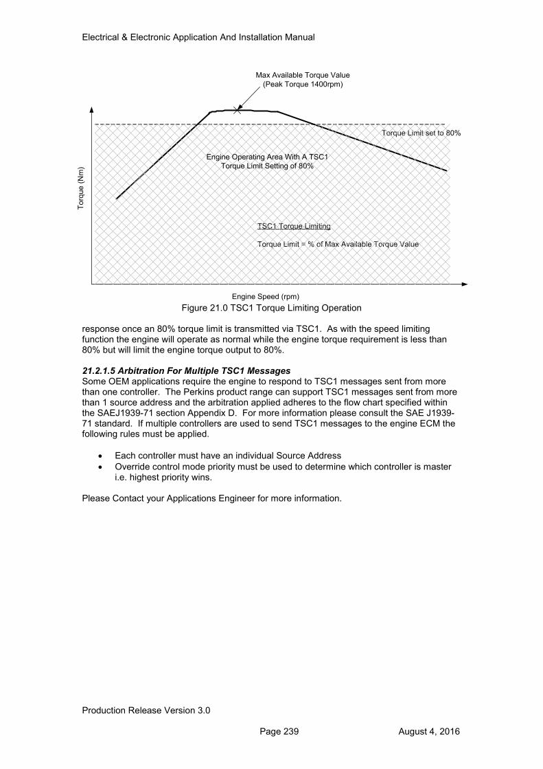
Electrical & Electronic Application And Installation Manual
Production Release Version 3.0 Page 239 August 4, 2016
Figure 21.0 TSC1 Torque Limiting Operation response once an 80% torque limit is transmitted via TSC1. As with the speed limiting function the engine will operate as normal while the engine torque requirement is less than 80% but will limit the engine torque output to 80%. 21.2.1.5 Arbitration For Multiple TSC1 Messages Some OEM applications require the engine to respond to TSC1 messages sent from more than one controller. The Perkins product range can support TSC1 messages sent from more than 1 source address and the arbitration applied adheres to the flow chart specified within the SAEJ1939-71 section Appendix D. For more information please consult the SAE J1939-71 standard. If multiple controllers are used to send TSC1 messages to the engine ECM the following rules must be applied.
• Each controller must have an individual Source Address
• Override control mode priority must be used to determine which controller is master i.e. highest priority wins.
Please Contact your Applications Engineer for more information.
Torq
ue (
Nm
)
Engine Speed (rpm)
Max Available Torque Value
(Peak Torque 1400rpm)
TSC1 Torque Limiting
Torque Limit = % of Max Available Torque Value
Torque Limit set to 80%
Engine Operating Area With A TSC1
Torque Limit Setting of 80%
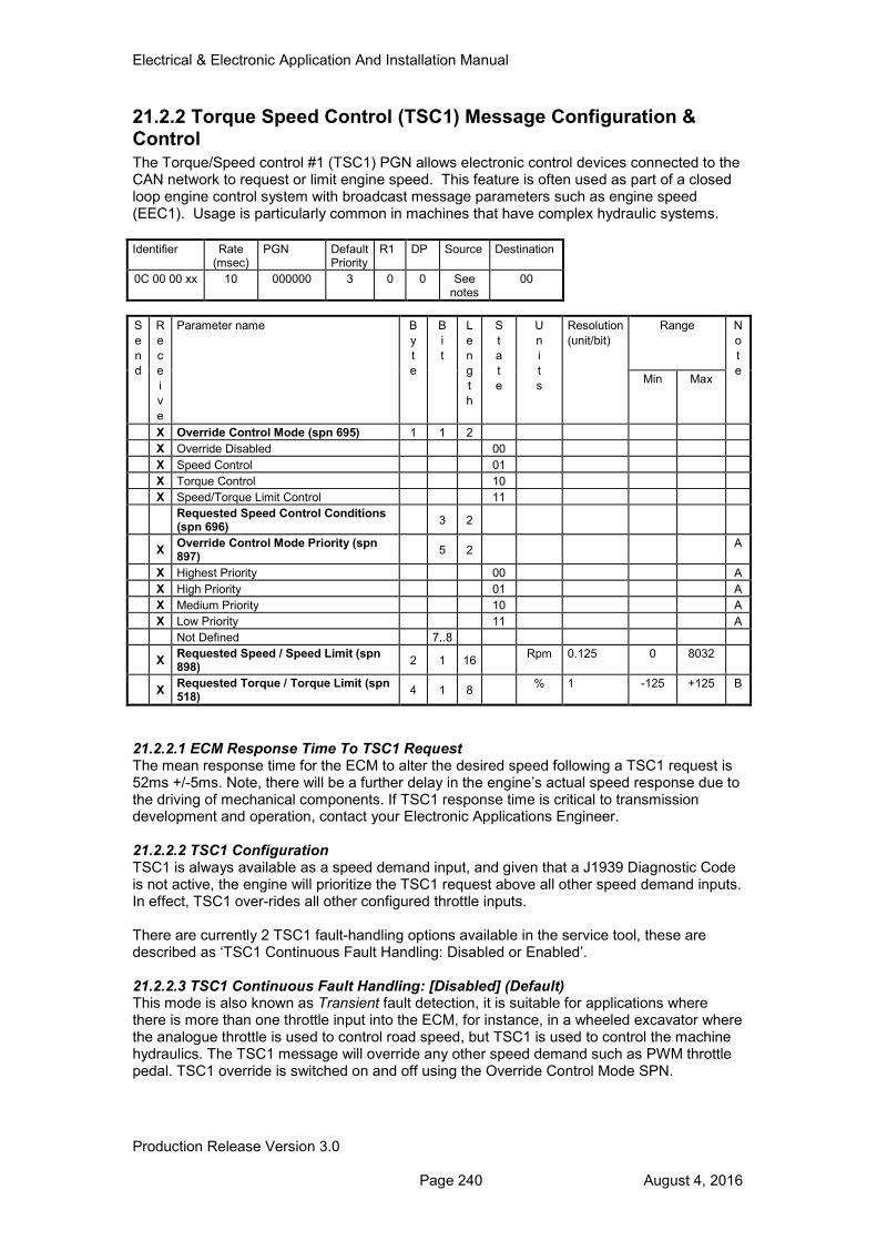
Electrical & Electronic Application And Installation Manual
Production Release Version 3.0 Page 240 August 4, 2016
21.2.2 Torque Speed Control (TSC1) Message Configuration & Control The Torque/Speed control #1 (TSC1) PGN allows electronic control devices connected to the CAN network to request or limit engine speed. This feature is often used as part of a closed loop engine control system with broadcast message parameters such as engine speed (EEC1). Usage is particularly common in machines that have complex hydraulic systems.
Identifier Rate (msec)
PGN Default Priority
R1 DP Source Destination
0C 00 00 xx 10 000000 3 0 0 See notes
00
S
e
n
d
R
e
c
e
i
v
e
Parameter name B
y
t
e
B
i
t
L
e
n
g
t
h
S
t
a
t
e
U
n
i
t
s
Resolution
(unit/bit)
Range N
o
t
e Min Max
X Override Control Mode (spn 695) 1 1 2
X Override Disabled 00
X Speed Control 01
X Torque Control 10
X Speed/Torque Limit Control 11
Requested Speed Control Conditions (spn 696)
3 2
X Override Control Mode Priority (spn 897)
5 2 A
X Highest Priority 00 A
X High Priority 01 A
X Medium Priority 10 A
X Low Priority 11 A
Not Defined 7..8
X Requested Speed / Speed Limit (spn 898)
2 1 16 Rpm 0.125 0 8032
X Requested Torque / Torque Limit (spn 518)
4 1 8 % 1 -125 +125 B
21.2.2.1 ECM Response Time To TSC1 Request The mean response time for the ECM to alter the desired speed following a TSC1 request is 52ms +/-5ms. Note, there will be a further delay in the engine’s actual speed response due to the driving of mechanical components. If TSC1 response time is critical to transmission development and operation, contact your Electronic Applications Engineer. 21.2.2.2 TSC1 Configuration TSC1 is always available as a speed demand input, and given that a J1939 Diagnostic Code is not active, the engine will prioritize the TSC1 request above all other speed demand inputs. In effect, TSC1 over-rides all other configured throttle inputs. There are currently 2 TSC1 fault-handling options available in the service tool, these are described as ‘TSC1 Continuous Fault Handling: Disabled or Enabled’. 21.2.2.3 TSC1 Continuous Fault Handling: [Disabled] (Default) This mode is also known as Transient fault detection, it is suitable for applications where there is more than one throttle input into the ECM, for instance, in a wheeled excavator where the analogue throttle is used to control road speed, but TSC1 is used to control the machine hydraulics. The TSC1 message will override any other speed demand such as PWM throttle pedal. TSC1 override is switched on and off using the Override Control Mode SPN.
Electrical & Electronic Application And Installation Manual
Production Release Version 3.0 Page 241 August 4, 2016
21.2.2.4 End of Transmission – Fault Detection The ECM needs to differentiate between the end of a transmission by another controller and an intermittent failure. The ECM expects, therefore, that when a controller no longer wishes to demand engine speed then it will terminate with at least one message with the Control Override Mode SPN set to 00. If the engine sees that TSC1 messages have stopped, for 500ms or more, and TSC1 has not been terminated correctly then the ECM will recognize this as a fault, a J1939 Diagnostic code will be raised and the ECM will not accept any TSC1 speed requests for the remainder of the key cycle. It is important to note that although the diagnostic limit for TSC1 signal rate is set at 500ms, customers should adhere to the 10ms transmission rate as detailed in Section 21.2.2 above where possible. This is to minimize the risk of the engine not behaving as the customer desires. 21.2.2.5 TSC1 Continuous Fault Handling: [Enabled] This mode is also known as Continuous fault detection, it is suitable for applications where either TSC1 is the only throttle used or where TSC1 is continuously used to limit the top engine speed. The TSC1 speed control / speed limit cannot be switched off using the Override Control Mode SPN. For instance, in a wheeled excavator the analogue throttle is connected to the machine ECM that sends the TSC1 message to control road speed, and to control the machine hydraulics. When TSC1 Continuous Fault Handling is active, other throttles will be permanently over-ridden, and will only become available if a TSC1 fault is detected. 21.2.2.6 Rating and Droop Control In addition to Torque Speed Control, the complimentary message ‘OHECS’ allows droop and rating selection over J1939 with a similar effect to the hard-wired ‘Mode Selection’ feature. The OHECS PGN is described later in this section.
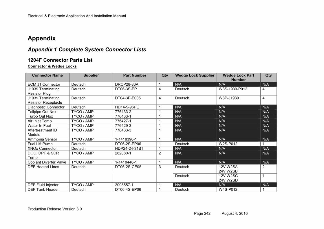
Electrical & Electronic Application And Installation Manual
Production Release Version 3.0 Page 242 August 4, 2016
Appendix
Appendix 1 Complete System Connector Lists
1204F Connector Parts List Connector & Wedge Locks
Connector Name Supplier Part Number Qty Wedge Lock Supplier Wedge Lock Part Number
Qty
ECM J1 Connector Deutsch DRCP28-86A 1 N/A N/A N/A
J1939 Terminating Resistor Plug
Deutsch DT06-3S-EP 4 Deutsch W3S-1939-P012 4
J1939 Terminating Resistor Receptacle
Deutsch DT04-3P-E005 4 Deutsch W3P-J1939 4
Diagnostic Connector Deutsch HD14-9-96PE 1 N/A N/A N/A
Tailpipe Out Nox TYCO / AMP 776433-2 1 N/A N/A N/A
Turbo Out Nox TYCO / AMP 776433-1 1 N/A N/A N/A
Air Inlet Temp TYCO / AMP 776427-1 1 N/A N/A N/A
Water In Fuel TYCO / AMP 776429-3 1 N/A N/A N/A
Aftertreatment ID Module
TYCO / AMP 776433-3 1 N/A N/A N/A
Ammonia Sensor TYCO / AMP 1-1418390-1 1 N/A N/A N/A
Fuel Lift Pump Deutsch DT06-2S-EP06 1 Deutsch W2S-P012 1
XNOx Connector Deutsch HDP24-24-31ST 1 N/A N/A N/A
DOC, DPF & SCR Temp
TYCO / AMP 282080-1 2 N/A N/A N/A
Coolant Diverter Valve TYCO / AMP 1-1418448-1 1 N/A N/A N/A
DEF Heated Lines Deutsch DT06-2S-CE05 3 Deutsch 12V W2SA 24V W2SB
2
Deutsch 12V W2SC 24V W2SD
1
DEF Fluid Injector TYCO / AMP 2098557-1 1 N/A N/A N/A
DEF Tank Header Deutsch DT06-4S-EP06 1 Deutsch W4S-P012 1
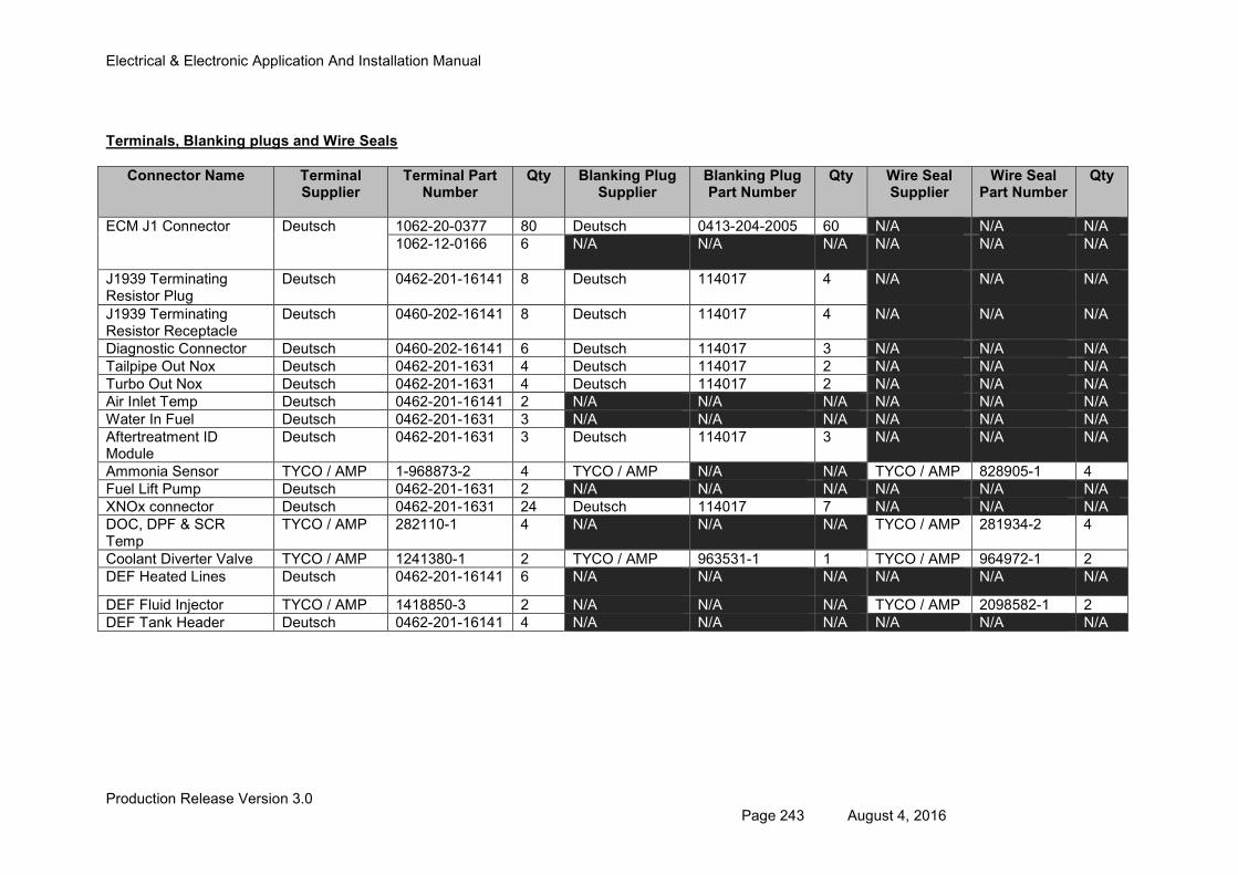
Electrical & Electronic Application And Installation Manual
Production Release Version 3.0 Page 243 August 4, 2016
Terminals, Blanking plugs and Wire Seals
Connector Name Terminal Supplier
Terminal Part Number
Qty Blanking Plug Supplier
Blanking Plug Part Number
Qty Wire Seal Supplier
Wire Seal Part Number
Qty
ECM J1 Connector Deutsch 1062-20-0377 80 Deutsch 0413-204-2005 60 N/A N/A N/A
1062-12-0166 6 N/A N/A N/A N/A N/A N/A
J1939 Terminating Resistor Plug
Deutsch 0462-201-16141 8 Deutsch 114017 4 N/A N/A N/A
J1939 Terminating Resistor Receptacle
Deutsch 0460-202-16141 8 Deutsch 114017 4 N/A N/A N/A
Diagnostic Connector Deutsch 0460-202-16141 6 Deutsch 114017 3 N/A N/A N/A
Tailpipe Out Nox Deutsch 0462-201-1631 4 Deutsch 114017 2 N/A N/A N/A
Turbo Out Nox Deutsch 0462-201-1631 4 Deutsch 114017 2 N/A N/A N/A
Air Inlet Temp Deutsch 0462-201-16141 2 N/A N/A N/A N/A N/A N/A
Water In Fuel Deutsch 0462-201-1631 3 N/A N/A N/A N/A N/A N/A
Aftertreatment ID Module
Deutsch 0462-201-1631 3 Deutsch 114017 3 N/A N/A N/A
Ammonia Sensor TYCO / AMP 1-968873-2 4 TYCO / AMP N/A N/A TYCO / AMP 828905-1 4
Fuel Lift Pump Deutsch 0462-201-1631 2 N/A N/A N/A N/A N/A N/A
XNOx connector Deutsch 0462-201-1631 24 Deutsch 114017 7 N/A N/A N/A
DOC, DPF & SCR Temp
TYCO / AMP 282110-1 4 N/A N/A N/A TYCO / AMP 281934-2 4
Coolant Diverter Valve TYCO / AMP 1241380-1 2 TYCO / AMP 963531-1 1 TYCO / AMP 964972-1 2
DEF Heated Lines Deutsch 0462-201-16141 6 N/A N/A N/A N/A N/A N/A
DEF Fluid Injector TYCO / AMP 1418850-3 2 N/A N/A N/A TYCO / AMP 2098582-1 2
DEF Tank Header Deutsch 0462-201-16141 4 N/A N/A N/A N/A N/A N/A
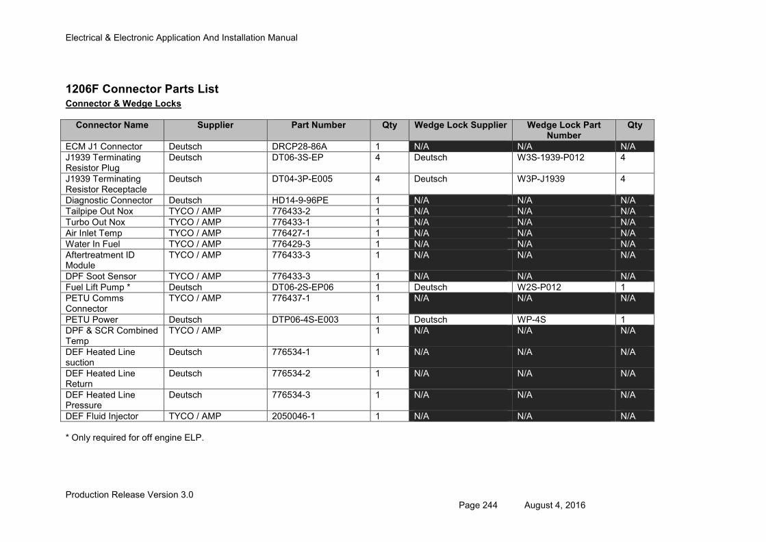
Electrical & Electronic Application And Installation Manual
Production Release Version 3.0 Page 244 August 4, 2016
1206F Connector Parts List Connector & Wedge Locks
Connector Name Supplier Part Number Qty Wedge Lock Supplier Wedge Lock Part Number
Qty
ECM J1 Connector Deutsch DRCP28-86A 1 N/A N/A N/A
J1939 Terminating Resistor Plug
Deutsch DT06-3S-EP 4 Deutsch W3S-1939-P012 4
J1939 Terminating Resistor Receptacle
Deutsch DT04-3P-E005 4 Deutsch W3P-J1939 4
Diagnostic Connector Deutsch HD14-9-96PE 1 N/A N/A N/A
Tailpipe Out Nox TYCO / AMP 776433-2 1 N/A N/A N/A
Turbo Out Nox TYCO / AMP 776433-1 1 N/A N/A N/A
Air Inlet Temp TYCO / AMP 776427-1 1 N/A N/A N/A
Water In Fuel TYCO / AMP 776429-3 1 N/A N/A N/A
Aftertreatment ID Module
TYCO / AMP 776433-3 1 N/A N/A N/A
DPF Soot Sensor TYCO / AMP 776433-3 1 N/A N/A N/A
Fuel Lift Pump * Deutsch DT06-2S-EP06 1 Deutsch W2S-P012 1
PETU Comms Connector
TYCO / AMP 776437-1 1 N/A N/A N/A
PETU Power Deutsch DTP06-4S-E003 1 Deutsch WP-4S 1
DPF & SCR Combined Temp
TYCO / AMP 1 N/A N/A N/A
DEF Heated Line suction
Deutsch 776534-1 1 N/A N/A N/A
DEF Heated Line Return
Deutsch 776534-2 1 N/A N/A N/A
DEF Heated Line Pressure
Deutsch 776534-3 1 N/A N/A N/A
DEF Fluid Injector TYCO / AMP 2050046-1 1 N/A N/A N/A
* Only required for off engine ELP.
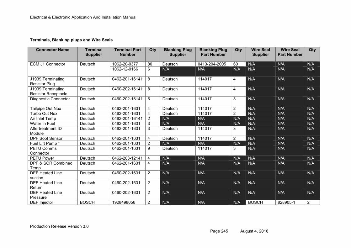
Electrical & Electronic Application And Installation Manual
Production Release Version 3.0 Page 245 August 4, 2016
Terminals, Blanking plugs and Wire Seals
Connector Name Terminal Supplier
Terminal Part Number
Qty Blanking Plug Supplier
Blanking Plug Part Number
Qty Wire Seal Supplier
Wire Seal Part Number
Qty
ECM J1 Connector Deutsch 1062-20-0377 80 Deutsch 0413-204-2005 60 N/A N/A N/A
1062-12-0166 6 N/A N/A N/A N/A N/A N/A
J1939 Terminating Resistor Plug
Deutsch 0462-201-16141 8 Deutsch 114017 4 N/A N/A N/A
J1939 Terminating Resistor Receptacle
Deutsch 0460-202-16141 8 Deutsch 114017 4 N/A N/A N/A
Diagnostic Connector Deutsch 0460-202-16141 6 Deutsch 114017 3 N/A N/A N/A
Tailpipe Out Nox Deutsch 0462-201-1631 4 Deutsch 114017 2 N/A N/A N/A
Turbo Out Nox Deutsch 0462-201-1631 4 Deutsch 114017 2 N/A N/A N/A
Air Inlet Temp Deutsch 0462-201-16141 2 N/A N/A N/A N/A N/A N/A
Water In Fuel Deutsch 0462-201-1631 3 N/A N/A N/A N/A N/A N/A
Aftertreatment ID Module
Deutsch 0462-201-1631 3 Deutsch 114017 3 N/A N/A N/A
DPF Soot Sensor Deutsch 0462-201-1631 4 Deutsch 114017 2 N/A N/A N/A
Fuel Lift Pump * Deutsch 0462-201-1631 2 N/A N/A N/A N/A N/A N/A
PETU Comms Connector
Deutsch 0462-201-1631 9 Deutsch 114017 3 N/A N/A N/A
PETU Power Deutsch 0462-203-12141 4 N/A N/A N/A N/A N/A N/A
DPF & SCR Combined Temp
Deutsch 0462-201-1631 4 N/A N/A N/A N/A N/A N/A
DEF Heated Line suction
Deutsch 0460-202-1631 2 N/A N/A N/A N/A N/A N/A
DEF Heated Line Return
Deutsch 0460-202-1631 2 N/A N/A N/A N/A N/A N/A
DEF Heated Line Pressure
Deutsch 0460-202-1631 2 N/A N/A N/A N/A N/A N/A
DEF Injector BOSCH 1928498056 2 N/A N/A N/A BOSCH 828905-1 2
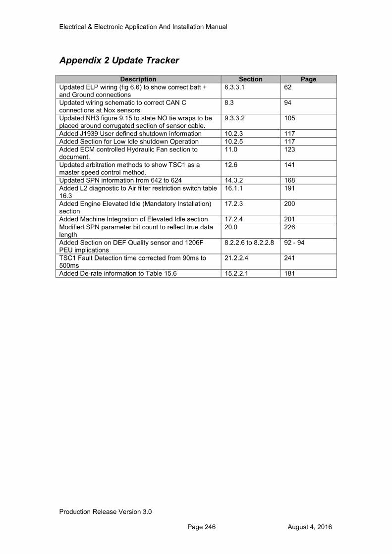
Electrical & Electronic Application And Installation Manual
Production Release Version 3.0 Page 246 August 4, 2016
Appendix 2 Update Tracker
Description Section Page
Updated ELP wiring (fig 6.6) to show correct batt + and Ground connections
6.3.3.1 62
Updated wiring schematic to correct CAN C connections at Nox sensors
8.3 94
Updated NH3 figure 9.15 to state NO tie wraps to be placed around corrugated section of sensor cable.
9.3.3.2 105
Added J1939 User defined shutdown information 10.2.3 117
Added Section for Low Idle shutdown Operation 10.2.5 117
Added ECM controlled Hydraulic Fan section to document.
11.0 123
Updated arbitration methods to show TSC1 as a master speed control method.
12.6 141
Updated SPN information from 642 to 624 14.3.2 168
Added L2 diagnostic to Air filter restriction switch table 16.3
16.1.1 191
Added Engine Elevated Idle (Mandatory Installation) section
17.2.3 200
Added Machine Integration of Elevated Idle section 17.2.4 201
Modified SPN parameter bit count to reflect true data length
20.0 226
Added Section on DEF Quality sensor and 1206F PEU implications
8.2.2.6 to 8.2.2.8 92 - 94
TSC1 Fault Detection time corrected from 90ms to 500ms
21.2.2.4 241
Added De-rate information to Table 15.6 15.2.2.1 181


![Electronic OPS manual installation and registration 17, 2012 [ELECTRONIC OPS MANUAL INSTALLATION AND REGISTRATION] 1 Electronic OPS Manual Installation and Registration The software](https://img.pdfslide.us/doc/110x75/5b01262c7f8b9a84338dbf2e/electronic-ops-manual-installation-and-17-2012-electronic-ops-manual-installation.jpg)