Embed Size (px)
Citation preview
University of South CarolinaScholar Commons
Faculty Publications Chemical Engineering, Department of
1991
Electrochemical Characterization of ElectronicallyConductive Polypyrrole on CyclicVoltammogramsTaewhan YeuTexas A & M University - College Station
Ken-Ming YinTexas A & M University - College Station
Jose CarbajalTexas A & M University - College Station
Ralph E. WhiteUniversity of South Carolina - Columbia, [email protected]
Follow this and additional works at: https://scholarcommons.sc.edu/eche_facpub
Part of the Chemical Engineering Commons
This Article is brought to you by the Chemical Engineering, Department of at Scholar Commons. It has been accepted for inclusion in FacultyPublications by an authorized administrator of Scholar Commons. For more information, please contact [email protected].
Publication InfoJournal of the Electrochemical Society, 1991, pages 2869-2877.© The Electrochemical Society, Inc. 1991. All rights reserved. Except as provided under U.S. copyright law, this work may not bereproduced, resold, distributed, or modified without the express permission of The Electrochemical Society (ECS). The archivalversion of this work was published in the Journal of the Electrochemical Society.http://www.electrochem.org/DOI: 10.1149/1.2085332http://dx.doi.org/10.1149/1.2085332
Electrochemical Characterization of Electronically Conductive Polypyrrole on Cyclic Voltammograms
Taewhan Yeu, *'1Ken-Ming Yin** Jose Carbajal, *'2 and Ralph E. White* Center for Electrochemical Engineering, Department of Chemical Engineering, Texas A&M University,
College Station, Texas 77843-3122.
ABSTRACT
Experimental and theoretical cyclic voltammograms for electronically conducting polypyrrole film are obtained from the identical conditions and compared to each other to characterize electrochemical behavior of the polymer. A compari- son of the simulated and experimental cyclic voltammograms shows quantitative agreement. The profiles of the depend- ent variables show that the switching process is governed by the availability of the counterion to the polypyrrole electrode and the amount of electroactive sites. Sensitivity analysis shows that the double layer effects have more influence in the cyclic voltammograms than the electrokinetic effects.
Electronically conductive polypyrroles are an extremely interesting class of materials that have gained popularity in the last decade. It has been accepted that the polypyr- role films have a number of potential technological appli- cations in the areas of energy storage (1-5), solar energy conversion (6-11), and electrochromic display devices (12-15). There is no doubt that polypyrrole is an interesting electrode material. However, the knowledge of electro- chemical switching behavior of polypyrrole films pub- lished to date remains far from complete. Among those un- settled problems, the electronic and ionic charge transport mechanisms within the polypyrrole films have been fun- damentally important since the switching process under most circumstances is controlled by these factors. Thus, an unders tanding of charge transport within these poly- mers is a prerequisite to developing further practical appli- cations.
Among the available electroanalytical techniques, the cyclic voltammetry technique has been widely used to un- derstand the electroactivity and the electrochemical prop- erties of polypyrrole films because it can better describe the characteristics of the electrochemical switching behav- ior between conducting and insulating states (12-19). In this paper, both experimental and theoretical approaches are used.
Experimental cyclic voltammetry is performed for elec- trochemically synthesized 1 ~m thick polypyrrole film doped with perchlorate in 1M LiC104-PC solution. A math- ematical model, which is based on the conservation of mass and charged species, the porous electrode theory, the double layer theory, and the modified Butler-Volmer-type pseudo homogeneous electrochemical reaction rate ex- pression, is developed. This model is an extension of previ- ous work published in this laboratory (20, 21). Since the electrochemical properties and microscopic structure of polypyrrole film are locally defected, volume-averaged values is used to describe local variables throughout the polymer film to account for the effect of their nonho- mogeneity (20, 21). The validity of the model is tested by comparing the model predictions to the experimental data.
The model is used to characterize dynamic behavior (i.e., the relationship between microscopic structure, charge transport, and electrochemical characteristics) within the polypyrrole films by studying the profiles of dependent variables. Also, the model is used to verify the interesting parameters to characterize the properties of polypyrrole by sensitivity analysis and studying the effect of each pa- rameter ;The efforts to estimate values for the parameters that would yield the best agreement between model pre- dictions and experimental data are included.
* Electrochemical Society Active Member. ** Electrochemical Society Student Member. 1Present Address: Duracell USA, Technical Center, Bethel, Con-
necticut 06801. 2Present Address: Inland Steel Company, Research Labora-
tories, East Chicago, Indiana 46312.
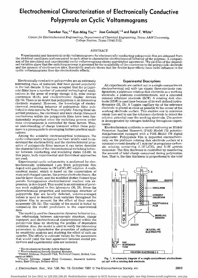
Experimental Descriptions All experiments are carried out in a s ingle-compartment
electrochemical cell with the classic three-electrode con- figuration; a plat inum rotating disk electrode as a working electrode, a pla t inum counterelectrode, and a saturated calomel reference electrode (SCE). A rotating disk elec- trode (RDE) is used here because of its well-defined hydro- dynamics (22, 23). A Luggin capillary tip of the reference electrode is placed as close as possible to the center of the working electrode surface. This enables one to minimize ohmic loss and to use the reference electrode to detect the solution potential near the working electrode. The system is deoxygenated by nitrogen bubbl ing throughout experi- ments.
Electrochemical synthesis is carried out using an EG&G Princeton Applied Research (PAR) Model 173 potentio- stat/galvanostat equipped with a PAR Model 179 digital coulometer. Polypyrrole film is deposited electrochemi- cally on the plat inum rotating disk electrode surface at a constant current density of 1 mA/cm 2 in propylene carbon- ate solution containing 0.1MLiCI04 and O.1M pyrrole monomer. The film thickness is controlled by monitoring the amount of total charge consumed during polymeriza- tion. That is, the film thickness is proportional to the total
i !i! .iii / co,,.Ec oR
\ ,2 LUGGIN
I IM LiCI04-PC ELECTROLYTE
jLo, DISPERSION TUBE
I COUNTER ELECTRODE (-) I
Fig. 1. A schematic diagram of a single-compartment electrochemi- cal cell with a rotating disk electrode.
J. Electrochem. Soc., Vol. 138, No. 10, October 1991 �9 The Electrochemical Society, tnc. 2869
Downloaded 14 Jun 2011 to 129.252.106.20. Redistribution subject to ECS license or copyright; see http://www.ecsdl.org/terms_use.jsp
2870 J. Electrochem. Soc., Vol. 138, No. 10, October 1991 �9 The Electrochemical Society, Inc.
passed charge, and 0.24 C/cm 2 of passed charge yields 1 ~tm th ick po lypyr ro le film (18, 19). The surface of plati- n u m disk e lec t rode is c leaned and pol i shed to a mi r ro r fin- ish wi th 1, 0.3, t hen 0.05 ~m a lumina p o w d e r (Banner Sci- entific) on a Met ron po l i sh ing cloth before polymerizat ion.
After the e l ec t rochemica l synthesis , the cell is thor- oughly r insed wi th p ropy lene carbona te and then filled wi th 1M LiC104-PC e lec t ro ly te solut ion to pe r fo rm the cy- clic vo l t ammet ry . Cycl ic v o l t a m m e t r y is accompl i shed us ing a P A R Model 173 potent ios ta t /ga lvanos ta t in con- j unc t i on wi th a P A R Model 175 p rogrammer , and resul t ing cur ren t dens i ty responses are r ecorded on a Hous ton In- s t rumen t s Model 2000 X-Y recorder .
All chemica l used are reagan t grade (Aldrich Chemicals). Pyr ro le is dist i l led twice in a v a c u u m and then s tored unde r ni t rogen. LiC104 is used wi thou t fur ther purifica- tion. The p ropy lene carbona te used as a so lvent is fur ther purif ied by fract ional dis t i l la t ion and percola t ion th rough ac t iva ted alumina. The wa te r in the p ropy lene carbona te is r e m o v e d by add ing molecu la r sieves for a few days. All e lec t ro ly te solut ions are p repared in a g love box under ni- t rogen a tmosphere .
Model Descriptions The model presented here is for predicting the cyclic
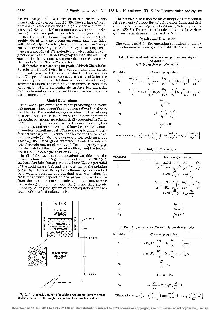
voltammetric behavior of the polypyrrole films doped with perchlorate. The modeling regions close to the rotating disk electrode, which are relevant to the development of the m o d e l equat ions , are schemat ica l ly p resen ted in Fig. 2.
The m o d e l i n g reg ions consis t of two main regions, two boundaries, and one interregional interface, and they must be modeled simultaneously. These are the boundary inter- face between a platinum current collector and the polypyr- role electrode (y = 0); the polypyrrole electrode region of width ~pp; the inter-regional interface between the polypyr- role electrode and an electrolyte diffusion layer (y = ypp); the electrolyte diffusion layer of width ~d~; and the bound- ary at a bulk electrolyte solution (y = Yal).
In all of the regions, the dependent variables are: the concentration of Li + (c+), the concentration of ClO~ (c_), the local faradaic charge per unit volume (Qf), the potential of the solid phase (~P~), and the potential of the solution phase (@~). Because the cyclic voltammetry is controlled by sweeping potential at a constant scan rate, values for these unknowns depend on the perpendicular distance from the platinum current collector of the polypyrrole el6ctrode (y) and applied potential (E), and they are ob- tained by solving the system of model equations for each region of the cell simultaneously.
The detailed discussion for the assumptions, mathemati- cal t r ea tmen t of proper t ies of po lypyr ro te films, and deri- va t ion of the govern ing equa t ions are g iven in previous works (20, 21). The sys tem of m o d e l equa t ions for each re- g ion and var iable are summar i zed in Table I.
Results and Discussion The values used for the operating conditions in the cy-
clic voltammograms are given in Table II. The applied po-
Table I. System of model equations for cyclic voltammetry of polypyrrole.
A. Polypyrrole electrode region.
Variables Governing equations
a(epc+) C+
C-
Qf
0bl
Ot
0(epc_)
at
o / a<I>~ + ~_l ac+ s+ - z+r- tD+'" ~) - - - ~ j
, a % \ . _ z_ F - - I u_ pc_ - - 1 + - - - aj
ay \ ay / 0!t \ ay / nF
aQf - a j
at
= - - O'p aj ay
qb2 ~z l c l = 0
c- - c~r W h e r e a j = a i o , ~ r { ( 1 - O ) ( ~ _ ~ f ) e x p ( ~ T ~ ) - O ~ p ( ~ - ~ ) }
B. Electrolyte diffusion layer.
Variables Governing equations
Oc+ z+D+F a ( ar a2c+ c + - - = - - c+ + D + -
at R T ay \ ay l ay 2 20c+ + a ' ~ (y - ~pp) - -
ay
Oc z_D_F a ( a % l 0u c_ - - = c- + D _ - -
at R T Oy ay I ay 2 ae-
+ a ' ~ (y _ ~pp)2 ay
R D E
PLATINUM CURRENT
COLLECTOR Iz
i:i:i:i:i:b0~:i:i:!:!:i : ":' :'P0bYPYI~ROLE" :': �9
. : : : : : : : : : : : : : : : : : : : : : :
:.' .:.:::::r::::::::;:::::::?:::
ELECTROLYTE DIFFUSION
LAYER
~ GGIN TiP
l , y=o
6pp !
-- t ~= YPP
t /
' - ~ y~- y,ll
Fig. 2. A schematic diagram of modeling regions closed to the rotat- ing disk electrode in the single-compartment electrochemical cell.
Qf Qf = 0
([/)1 ~1 = 0
~P2 ~zicl = 0 "y
C. Boundary at current collector/polypyrrole electrode.
Variables Governing equations
c3gP2 ac+ s+ c+ - z + U + , p F c + - - - D+,p aj
Oy Oy nF
0@2 Oc_ s_ c - z U _ , p F c _ - - - D .p a j
Oy Oy nF
aQf Q~ - - = a3
ot
qbl @l=E+qbref
Oep~ Oci r - Kp . . . . . F ~ z,D,,p Oy = 0
Oy
W h e r e a j = a i o r e f [ / l _ o ~ [ C ~ /~aF ~ / - ( ~ c r \ ] ' tt )t 7 exp t ~ vl / - O exp t ~ ' r i J J
Downloaded 14 Jun 2011 to 129.252.106.20. Redistribution subject to ECS license or copyright; see http://www.ecsdl.org/terms_use.jsp
J. Electrochem. Soc., Vol. 138, No. 10, October 1991 �9 The Electrochemical Society, Inc. 2871
D. Interface at polypyrrole electrode/diffusion layer.
Variables Governing equations
0 ( I ) 2 0 C + ~ ) 2 0 C + C+ - - Z + U + , p F C + - - - D + , p - = - Z + U + F C + - - D + - -
oy oy oy oy
C
Qf
q)l
(P2
o(P2 oc 0(I)2 ~c - z _ u , p F c _ - - D_,p - - = - z _ u _ F c - - - D_ - -
Oy Oy oy Oy
oQ._~f = 0 oy I ypp
= 0 (~Y ypp
O(P2 Oc~ OdP2 Ocl - - Kp - - - - F ~ . . . . . K - - - - F~ziDi - - Oy z,D~,p Oy Oy i Oy
2 , 0 . . . , , . . , , . . , �9 , .
2 0 m V / s e c
i 0.0
Z
- I , O
- 2 .C , , , I , , F , , , I ,
�9 0 . 8 - 0 . 4 O,O 0 , 4 0 , 8
A P P L I E D P O T E N T I A L (V) v s . SCE
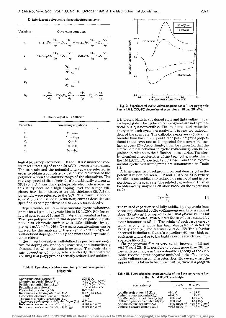
Fig. 3. Experimental cyclic voltammogroms for a 1 I~m polypyrrole film in 1M LiCIO4-PC electrolyte at scan rates of 10 and 20 mV/s.
E. Boundary at bulk solution,
Variables Governing equations
C+ C + - C + , r e f
C - C - - = C - , r e f
Qf Qf = 0 (I)1 dP 1 = 0 (D2 ([D2 = ( ~ r e f
t en t i a l (E) s w e e p s b e t w e e n -0 .8 a n d +0.8 V u n d e r t he con- s t a n t s c a n ra t e s (v~) of 10 a n d 20 mV/s at r o o m t e m p e r a t u r e . T h e s can ra te a n d t h e p o t e n t i a l i n t e rva l we re se lec ted in o r d e r to o b t a i n a c o m p l e t e o x i d a t i o n a n d r e d u c t i o n of t he p o l y m e r w i t h i n t h e s t ab i l i ty r a n g e of t he e lectrolyte . T h e r o t a t i n g s p e e d of d i sk e l ec t rode (12) is a rb i t r a r i ly c h o s e n as 3600 rpm. A 1 ~ m t h i c k po lypy r ro l e e l ec t rode is u s e d in t h i s s t u d y b e c a u s e a h i g h d o p i n g level a n d a h i g h effi- c i e n c y h a v e b e e n o b s e r v e d for th i s t h i c k n e s s (2), All t he p o t e n t i a l s w e r e r e f e r r ed to t he SCE. T he r e s u l t i n g a n o d i c (ox ida t ion) a n d c a t h o d i c ( r educ t ion) c u r r e n t dens i t i e s are spec i f ied as b e i n g pos i t i ve a n d nega t ive , respec t ive ly .
E x p e r i m e n t a l r e s u I t s . - - E x p e r i m e n t a l cyclic v o l t a m m o - g r a m s for a 1 ~ m po lypy r r o l e fi lm in 1M LiC104-PC elect ro- ly te a t s c a n ra t e s of 10 a n d 20 mV/s are p r e s e n t e d in Fig. 3. T h e 1 ~ m po lypy r ro l e f i lm was d e p o s i t e d on p o l i s h e d plati- n u m d i sk e l ec t rode su r face w i t h l i t t le di f f icul ty b y ap- p ly ing 1 m A / c m 2 for 240 s. Two m a i n c o n s i d e r a t i o n s can b e d e r i v e d b y t he ana lys i s of t h e s e cycl ic v o l t a m m o g r a m s ; we l l -de f ined d o p i n g - u n d o p i n g b e h a v i o r s a n d large capaci- t a n c e effects.
T h e c u r r e n t d e n s i t y is we l l -de f ined as pos i t ive a n d nega- t ive for d o p i n g a n d u n d o p i n g p rocesses , a n d i m m e d i a t e l y c h a n g e s s ign w h e n t h e s c a n is r eve r sed . T he e l ec t rochro - mic p r o p e r t i e s of po l ypy r r o l e are c lear ly d e m o n s t r a t e d s h o w i n g t h a t p o l y p y r r o l e is ac tua l ly r e d u c e d a n d oxidized;
Table II. Operating conditions used for cyclic voltammograms of polypyrrole.
Operating temperature (T) Negative potential limit (En~g) Positive potential limit (Epo~) Potential scan rate (vs) Disk rotation velocity (12) Reference electrode potential (dPr~r) Geometric electrode surface area (A) Thickness of polypyrrole film (Spp) Thickness of electrolyte diffusion layer (Sdl) Reference concentration of LP (C+,ref) Reference concentration of C10~ (c-,ref)
298.15 K -0.8 V (vs. SCE) +0.8 V (vs. SCE) 10 and 20 mV/s 377 rad/s 0.0 V (vs. SCE) 1 c m 2
1 ~m 0.01 cm 0.001 mol/cm 3 0.001 mol/cm 3
it is b r o w n - b l a c k in t h e d o p e d s ta te a n d l igh t ye l low in t he u n d o p e d state. T h e cycl ic v o l t a m m o g r a m s are no t s y m m e - t r ica l b u t quas i - r eve r s ib le . The ox ida t i ve a n d r e d u c t i v e c h a r g e s in e a c h cycle are e q u i v a l e n t to a n d are i n d e p e n - d e n t of t h e s c a n rate. T h e c a t h o d i c p e a k s are s ign i f ican t ly b r o a d e r t h a n t h e a m o d i c peaks . T h e p e a k h e i g h t is p ropor - t iona l to t he s c a n ra te as is e x p e c t e d for a r eve r s ib l e sur- face p roce s s (24). Acco rd ing ly , i t c an b e s u g g e s t e d t h a t t he e l c t r ochemica ] b e h a v i o r in cycl ic v o l t a m m e t r y can b e ex- p l a ined in r e l a t i on to t h e d i f fus ion of coun t e r i on . T h e elec- t r o c h e m i c a l cha rac t e r i s t i c s of t h e 1 ~ m po lypyr ro l e fi lm in t h e 1M LiC104-PC e lec t ro ly te o b t a i n e d f rom t h e s e exper i - m e n t a l cycl ic v o l t a m m o g r a m s are s u m m a r i z e d in Tab le III.
A la rge capac i t i ve b a c k g r o u n d c u r r e n t d e n s i t y (ic) in t he p o t e n t i a l r eg ion b e t w e e n +0.2 a n d +0.8 V v s . SCE (where t h e fi lm is n o t ox id i zed or r e d u c e d ) is o b s e r v e d a n d is pro- p o r t i o n a l to t he s c a n rate. T h e r e l a t ed capac i t ance , C1, m a y b e o b t a i n e d b y s i m p l e ca l cu l a t i on b a s e d on t h e e x p r e s s i o n (4, 25)
io C1 - [1]
V s
T h e r e l a t ed c a p a c i t a n c e of ful ly ox id i zed po lypy r ro l e f r o m t h e s e e x p e r i m e n t a l cycl ic v o l t a m m o g r a m s h a v e a v a l u e of a b o u t 85 m F / c m 2 ( c o m p a r e d to t he u sua l ~ F / c m 2 va lues for t h e b a r e e lec t rodes) , w h i c h is s imi la r to va lues o b t a i n e d b y o t h e r l abo ra to r i e s (25, 4). T h e or ig in of s u c h la rge capaci- t a n c e in p o l y m e r f i lms h a s b e e n d i s c u s s e d in de ta i l b y T a n g u y e t a l . (26) a n d M e r m i l l i o d e t a l . (27) The b e h a v i o r o b s e r v e d is s imi la r to t h a t of a c apac i t o r w i t h v e r y h i g h ca- p a c i t a n c e a n d is d u e to t h e h i g h l y p o r o u s s t r u c t u r e of pol- ypy r ro l e f i lms (16).
T h e po lypy r ro l e fi lm is ve ry s t ab l e b e t w e e n -0 .8 a n d +0.8 V v s . SCE. I t is p o s s i b l e to o b t a i n m o r e t h a n 200 cy- cles w i t h no c h a n g e in t h e c o u l o m b i c capac i ty of t he elec- t rode . E x t e n d i n g t he n e g a t i v e l imi t h a d l i t t le ef fec t on t he cycl ic v o l t a m m o g r a m charac te r i s t i c s . Howeve r , w h e n t h e u p p e r l im i t is t a k e n to b e m o r e posi t ive , t h e r e is a p rogres -
Table III. Electrochemical characteristics of the 1 I~m polypyrrole film in the 1M LiCIO4-PC electrolyte.
Scan rate (vs) 10 mV/s 20 mV/s
Anodic peak potential (Epa) Cathodic peak potential (Epc) Anodic peak current density (ipa) Cathodic peak current density (ipc Anodic charge density (Qca) Cathodic charge density (Qcc)
-0.1 V -0.04 V -0.43 V -0.45 V +0.95 mA +1.86 mA -0.72 mA -1.42 mA +5.63 mC/cm ~ +56.3 mC/cm 2 -53.8 mC/cm 2 -53.8 mC/cm 2
Downloaded 14 Jun 2011 to 129.252.106.20. Redistribution subject to ECS license or copyright; see http://www.ecsdl.org/terms_use.jsp
2872 d. Electrochem. Soc., Vol. 138, No. 10, October 1991 �9 The Electrochemical Society, Inc.
Table IV. Fixed parameter values used for polypyrrole.
Faradaic charge of neutral polypyrrole (Qf, red) Faradaic charge of oxidized polypyrrole (Qf, o~d) Porosity of neutral polypyrrole (e~d) Porosity of oxidized polypyrrole (eo~d) Double layer constant (a*) Zero charge potential (~pze) Exponent on porosity term (ex) Exchange current density (aio ~f) Anodic transfer coefficient (~aj Cathodic transfer coefficient (%) Open-circuit potential (U~f) Number of electron (n)
1.0 • 10 -s C/era 3 120.0 C/cm a~ 1.0 x 10 -2 1.0 • 10 -3 2.8/V a -0.3 V (vs. SCE) 0.5 ~ 10.0 A/cm s~ 0.7 ~ 0.3 ~ 3.087 V (vs. Li) 1
*Estimated values.
sive loss of capaci ty and film deter iora t ion takes p lace after a few cycles.
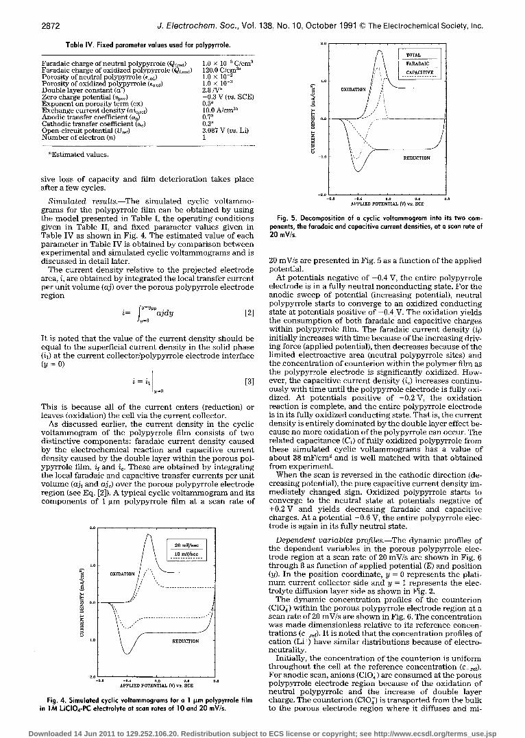
Simula ted results .--The s imula ted cyclic vo l t ammo- g rams for the po lypyr ro le film can be obta ined by us ing the m o d e l p re sen ted in Table I, the opera t ing condi t ions g iven in Table II, and f ixed pa rame te r va lues g iven in Table IV as s h o w n in Fig. 4. The es t imated va lue of each pa ramete r in Table IV is ob ta ined by compar i son be tween expe r imen ta l and s imula ted cyclic v o l t a m m o g r a m s and is d i scussed in detai l later.
The cur ren t dens i ty re la t ive to the pro jec ted e lec t rode area, i, are ob ta ined by in tegra ted the local t ransfer cur ren t per uni t v o l u m e (aj) over the porous po lypyr ro le e lec t rode reg ion
i= fi _7"ajdy [2]
It is no ted that the va lue of the cur ren t dens i ty should be equa l to the superf ic ia l cur ren t dens i ty in the solid phase (i~) at the cur ren t co l lec tor /polypyrro le e lec t rode interface (y : 0)
i = il ~=0 [3]
This is because all of the cur ren t enters (reduction) or leaves (oxidation) the cell via the cur ren t collector.
As d i scussed earlier, the cur ren t dens i ty in the cyclic v o l t a m m o g r a m of the po lypyr ro le film consis ts of two d is t inc t ive componen t s : faradaic cur ren t dens i ty caused by the e l ec t rochemica l reac t ion and capaci t ive cur ren t dens i ty caused by the doub le layer wi th in the porous pal- ypyr ro le film, if and i~. These are ob ta ined by in tegra t ing the local faradaic and capaci t ive t ransfer cur rents pe r uni t v o l u m e (aj~ and ajc) over the porous po lypyr ro le e lec t rode reg ion (see Eq. [2]). A typical cycl ic v o l t a m m o g r a m and its c o m p o n e n t s of 1 ~m po lypyr ro le film at a scan rate of
I I
o .o
-1.o ~ REDUCTION
- 2 . 0 , , , I , , , I , , , r , , ,
- o . e - 0 . 4 o . o o , 4 o . 6
APPLIED POTENTIAL (Y) vs. SCE
Fig. 4. Simulated cyclic voltammogroms for a 1 ~m polypyrrole film in 1M LiCIO4-PC electrolyte at scan rates of 10 and 20 mV/s.
�9 . . , �9 . , , . . .
TOTAL
FARADAIC
.... c~ci~i~ .... 1.o
OXIDATION
~ n.o -
-l.o
- ~ ' ~ 8 ' ' i , , t , , , i , , , �9 - 0 . 4 0 . 0 0 . ~ 0 , 8
APPLIED POTENTIAL (V) v s . SCE
Fig. 5. Decomposition of a cyclic voltammogrom into its two com- ponents, the faradaic and capacitive current densities, at a scan rate of 20 mV/s.
20 mV/s are p resen ted in Fig. 5 as a func t ion of the appl ied potent ial .
At potent ia ls nega t ive of -0 .4 V, the ent i re po lypyr ro le e lec t rode is in a ful ly neut ra l n o n c o n d u c t i n g state. For the anodic sweep of potent ia l ( increasing potential) , neutra l po lypyr ro le starts to converge to an oxid ized conduc t ing state at potent ia ls pos i t ive of -0 .4 V. The ox ida t ion yields the c o n s u m p t i o n of bo th faradaic and capaci t ive charges wi th in po lypyr ro le film. The faradaic cur ren t dens i ty (if) ini t ial ly increases wi th t ime because of the increas ing driv- ing force (appl ied potential) , t hen decreases because of the l imi ted e lec t roac t ive area (neutral po lypyr ro le sites) and the .concentrat ion of coun te r ion wi th in the po lymer film as the po lypyr ro le e lec t rode is s ignif icant ly oxidized. How- ever, the capaci t ive cur ren t dens i ty (ic) increases cont inu- ously wi th t ime unt i l the po lypyr ro le e lec t rode is fully oxi- dized. At potent ia ls pos i t ive of +0.2 V, the ox ida t ion react ion is comple te , and the ent i re po lypyr ro le e lec t rode is in its ful ly ox id ized conduc t ing state. That is, the cur ren t dens i ty is en t i re ly d o m i n a t e d by the doub le layer effect be- cause no more ox ida t ion of the po lypyr ro le can occur. The re la ted capac i tance (C1) of fully ox id ized polypyrro le f rom these s imula ted cyclic v o l t a m m o g r a m s has a va lue of about 38 m F / c m 2 and is wel l m a t c h e d wi th that ob ta ined f rom exper imen t .
When the scan is r eve r sed in the ca thod ic d i rec t ion (de- c reas ing potential) , the pure capaci t ive cur ren t dens i ty ira- med ia te ly changed sign. Oxidized polypyrro le starts to converge to the neut ra l state at potent ia ls nega t ive of +0 .2V and yields decreas ing faradaic and capaci t ive charges. At a potent ia l -0 .6 V, the ent i re po lypyr ro le elec- t rode is again in its fully neut ra l state.
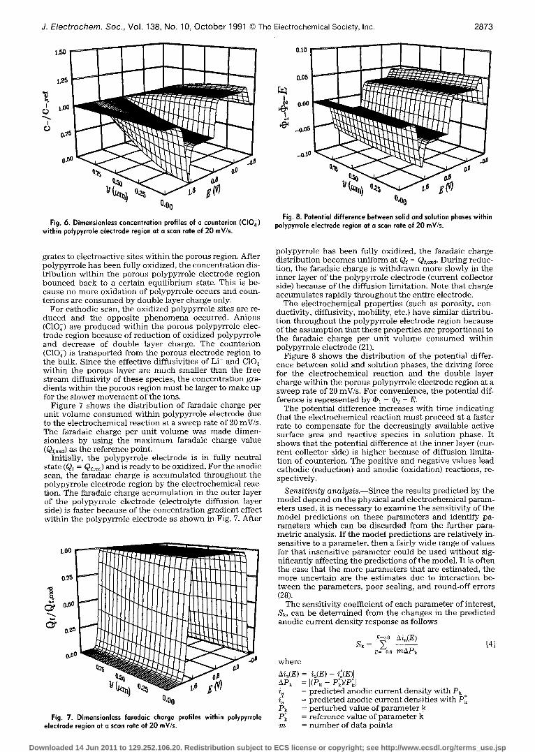
Dependent variables profiles.--The dynamic profiles of the d e p e n d e n t var iables in the porous po lypyr ro le elec- t rode reg ion at a scan rate of 20 mV/s are shown in Fig. 6 t h rough 8 as func t ion of app l ied potent ia l (E) and posi t ion (y). In the posi t ion coordinate , y = 0 represen t s the plati- n u m cur ren t co l lec tor s ide and y = 1 represen t s the elec- t ro lyte di f fus ion layer side as shown in Fig. 2.
The dynamic concen t ra t ion profi les of the coun te r ion (C10~) wi th in the porous po lypyr ro le e lec t rode reg ion at a scan rate of 20 mV/s are shown in Fig. 6. The concen t ra t ion was m a d e d imens ion less re la t ive to its re fe rence concen- t ra t ions (c-,ref). I t is no ted that the concen t ra t ion profiles of cat ion (Li § have s imilar d is t r ibut ions because of electro- neutral i ty .
Initially, the concen t ra t ion of the coun te r ion is un i fo rm th roughou t the cell at the re ference concen t ra t ion (c ,ret)- For anodic scan, anions (C10~) are c o n s u m e d at the porous po lypyr ro le e lec t rode reg ion because of the ox ida t ion o f neutra l po lypyr ro le and the increase of doub le layer charge. The coun te r ion (C10~) is t r anspor t ed f rom the bu lk to the porous e lec t rode reg ion whe re it diffuses and mi-
Downloaded 14 Jun 2011 to 129.252.106.20. Redistribution subject to ECS license or copyright; see http://www.ecsdl.org/terms_use.jsp
0.10
1.25
f,~ 1.00
0.50
0.00
Fig. 6. Dimensionless concentration profiles of a counterion (CI04) within polypyrrole electrode region at a scan rate of 20 mV/s.
0.05
..o.lO
! o.oo
_o.o5
~0
i J
~.0 0
J. Electrochem. Soc., Vol. 138, No. 10, October 1991 �9 The Electrochemical Society, Inc. 2873
Fig. 8. Potential difference between solid and solution phases within polypyrrole electrode region at a scan rate of 20 mV/s.
grates to electroactive sites within the porous region. After polypyrrole has been fully oxidized, the concentration dis- tribution within the porous polypyrrole electrode region bounced back to a certain equil ibrium state. This is be- cause no more oxidation of polypyrrole occurs and coun- terions are consumed by double layer charge only.
For cathodic scan, the oxidized polypyrrole sites are re- duced and the opposite phenomena occurred. Anions (C104) are produced within the porous polypyrrole elec- trode region because of reduction of oxidized polypyrrole and decrease of double layer charge. The counterion (C104) is transported from the porous electrode region to the bulk. Since the effective diffusivities of Li § and C10~ within the porous layer are much smaller than the free stream diffusivity of these species, the concentration gra- dients within the porous region must be larger to make up for the slower movement of the ions.
Figure 7 shows the distribution of faradaic charge per unit volume consumed within polypyrrole electrode due to the electrochemical reaction at a sweep rate of 20 mV/s. The faradaic charge per unit volume was made dimen- sionless by using the max imum faradaic charge value (Qf.oxd) as the reference point.
Initially, the polypyrrole electrode is in fully neutral state (Qf = Qf.r~d) and is ready to be oxidized. For the anodic scan, the faradaic charge is accumulated throughout the polypyrrole electrode region by the electrochemical reac- tion. The faradaic charge accumulation in the outer layer of the polypyrrole electrode (electrolyte diffusion layer side) is faster because of the concentration gradient effect within the polypyrrole electrode as shown in Fig. 7. After
1.00 " ~
! 0,5
0.50
0.25
0.00 " ~ ~ r
(}.O0
Fig. 7. Dimensionless faradaic charge profiles within polypyrrole electrode region at a scan rate of 20 mV/s.
polypyrrole has been fully oxidized, the faradaic charge distribution becomes uniform at Qf = Qf, oxa. During reduc- tion, the faradaic charge is withdrawn more slowly in the inner layer of the polypyrrole electrode (current collector side) because of the diffusion limitation. Note that charge accumulates rapidly throughout the entire electrode.
The electrochemical properties (such as porosity, con- ductivity, diffusivity, mobility, etc.) have similar distribu- tion throughout the polypyrrole electrode region because of the assumption that these properties are proportional to the faradaic charge per unit volume consumed within polypyrrole electrode (21).
Figure 8 shows the distribution of the potential differ- ence between solid and solution phases, the driving force for the electrochemical reaction and the double layer charge within the porous polypyrrole electrode region at a sweep rate of 20 mV/s. For convenience, the potential dif- ference is represented by (Pl - (P2 - E.
The potential difference increases with time indicating that the electrochemical reaction must proceed at a faster rate to compensate for the decreasingly available active surface area and reactive species in solution phase. It shows that the potential difference at the inner layer (cur- rent collector side) is higher because of diffusion limita- tion of counterion. The positive and negative values lead cathodic (reduction) and anodic (oxidation) reactions, re- spectively.
S e n s i t i v i t y a n a l y s i s . - - S i n c e the results predicted by the model depend on the physical and electrochemical param- eters used, it is necessary to examine the sensitivity of the model predictions on these parameters and identify pa- rameters which can be discarded from the further para- metric analysis. If the model predictions are relatively in- sensitive to a parameter, then a fairly wide range of values for that insensitive parameter could be used without sig- nificantly affecting the predictions of the model. It is often the case that the more parameters that are estimated, the more uncertain are the estimates due to interaction be- tween the parameters, poor sealing, and round-off errors (28).
The sensitivity coefficient of each parameter of interest, Sk, can be determined from the changes in the predicted anodic current density response as follows
E-0.s Aia(E) sk= E [4]
E=-o.8 m A P k
where
hia(E) = [ia(E) - i:(E)[ ARk [(Pk -- P~)/P~ !2 = predicted anodic current density with Pk ~a = predicted anodic current densities with P~ P k = perturbed value of parameter k P~ = reference value of parameter k m = number of data points
Downloaded 14 Jun 2011 to 129.252.106.20. Redistribution subject to ECS license or copyright; see http://www.ecsdl.org/terms_use.jsp
2874 J. Electrochem. Soc., Vol. 138, No. 10, October 1991 �9 The Electrochemical Society, Inc.
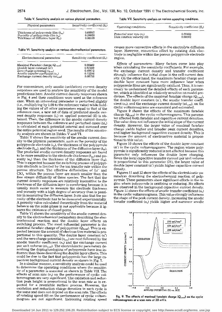
Table Y. Sensitivity analysis on various physical parameters.
Physical parameters Sensitivity coefficient (Sk)
Thickness of polypyrrole film (Spp) Porosity of polypyrrole film (%) Thickness of diffusion layer (Sdl)
0.68867 0.20020 0.06169
Table VII. Sensitivity analysis on various operating conditions.
Operating conditions Sensitivity coefficient (Sk)
Potential scan rate (v~) 0.66468 Disk rotation velocity (fl) 0.00002
Table VI. Sensitivity analysis on various electrochemical parameters.
Electrochemical parameters Sensitivity coefficient (Sk)
Maximal Faradaic charge (Qf, o~d) Double layer constant (a*) Zero charge potential (%~c) Anodic transfer coefficient (~) Exchange current density (aio,~f)
0.66469 0.52289 0.49472 0.12216 0.08758
For convenience, only anodic (oxidation) current density responses are used to analyze the sensitivity of the model predictions here. Anodic current density responses shown in Fig. 4 and their conditions were used as the reference case. When an interesting parameter is perturbed slightly (i.e., multiplying by 1.05 to the reference value) while hold- ing the values of all other parameters equal to that of the reference case, a new set of data of predicted anodic cur- rent density responses (i~) vs. applied potential (E) is ob- tained. Then, the difference in the anodic current density responses between the reference and perturbed cases (A/a) is calculated at each potential interval and summed over the entire potential region used. The results of the sensitiv- ity analysis are shown in Tables V and VI.
Table V shows the sensitivikv of the anodic current den- sity to the physical parameters, such as the porosity of the polypyrrole electrode (ep), the thickness of the polypyrrole electrode (Spp), and the thickness of the diffusion layer (Bdl). The predicted anodic current density responses are found to be more sensitive to the electrode thickness (8~p) and po- rosity (%) than the thickness of the diffusion layer (8di). This is expected because the switching process of polypyr- role electrode is limited by the ion transfer rate within the porous structure. The effective diffusivities of Li + and CIO 4 within the porous layer are much smaller than the free stream diffusivity of these species. The fact that the current density responses are relatively insensitive to the thickness of the diffusion layer is comforting because it is usually much easier to measure the electrode thickness and porosity with a high degree of accuracy than is possi- ble in measuring the diffusion layer. Note also that the po- rosity of the electrode has to be measured experimentally. A porosity value calculated theoretically from the material balance on the solid phase is not applicable because it ig- nores the existence of closed pores.
Table VI shows the sensitivity of the anodic current den- sity to the electrochemical parameters describing the elec- trochemical reaction and the double layer effects on switching process. The most influential parameter is the maximal faradaic charge of polypyrrole (Qf.oxd). This is ex- pected because the amount of electroactive material is pro- portional to this quantity. The double layer constant (a*) and the zero charge potential (~pzr are next followed by the anodic transfer coefficient (~) and the exchange current per unit volume (aio.ref). The electrokinetie parameters de- scribing the doping/undoping of polypyrrole have less in- fluence than those describing the double layer effects. This could be due to the fact that polypyrrole has the large ca- pacitive background current density as shown in Fig. 7.
In a similiar manner, a sensitivity analysis could be used to determine the operating conditions where the sensitiv- ity of a parameter is maximal as shown in Table VII. The effects of scan rate (Vs) on the performance of cyclic vol- tammogram are very significant. The oxidation and reduc- tion peak height is proportional to the scan rate as is ex- pected for a reversible surface process. However, the oxidation and reduction charge densities in each cycle is the same and does not depend on the scan rate. The effects of rotating speed (ft) on the performance of cyclic voltam- mogram are not significant. Increasing rotating speed
causes more convective effects in the electrolyte diffusion layer. However, convective effect by rotating disk elec- trode is negligible within the porous polypyrrole electrode region.
Effects of parameters.--Many factors come into play when calculating the sensitivity coefficients. For example, the exchange current density and transfer coefficient strongly influence the initial slope in the cell current den- sity. On the other hand, the maximum faradaic charge and double layer constant have more influence later when polypyrrole films are significantly oxidized. Thus, it is nec- essary to unders tand the detailed effects of each parame- ter, which is identified as relatively sensitive on model pre- diction. The effects of the maximal faradaic charge (Qf, oxd), the double layer constant (a*), the anodic transfer coeffi- cient (~a), and the exchange current density (aio,ref), on the cyclic voltammograms are examined and estimated.
Figure 9 shows the effects of the max imum faradaic charge (Qf, oxd) in the cyclic voltammograms. This parame- ter affected both faradaic and capacitive current densities. The value does not influence the initial slope of the current density. However, the larger value of maximal faradaic charge yields higher and broader peak current densities, and higher background capacitive current density. This is because the amount of electroactive material is propor- tional to this value.
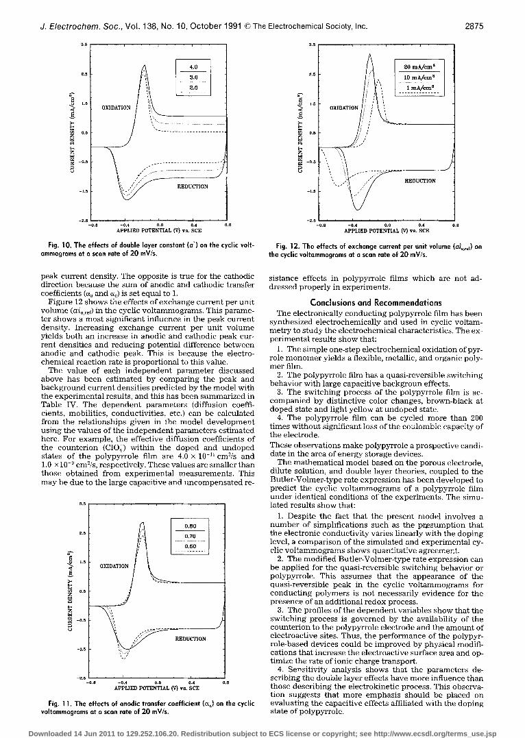
Figure 10 shows the effects of the double layer constant (a ~) in the cyclic voltammograms. The region where poly- pyrrole is significantly reduced is not affected because this parameter only influences the double layer charging. Since the local capacitive transfer current per uni t volume is proportional to this parameter (21), the larger value of double layer constant (a ~) yields higher capacitive current density.
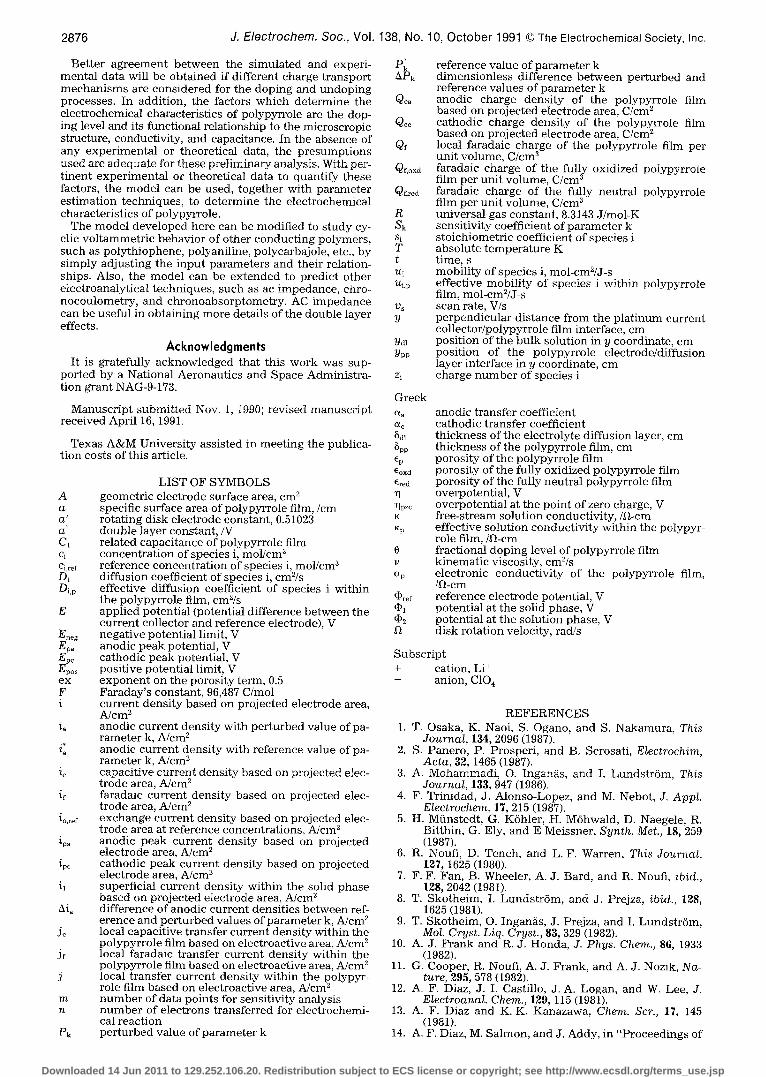
Figures 11 and 12 show the effects of the electrokinetic pa- rameters describing the electrochemical reaction of poly- pyrrole. These parameters show significant effects in the re- gion where polypyrrole is oxidizing or reducing. No effects are observed in the background capacitive current density. Figure 11 shows the effects of anodic transfer coefficient (a~) in the cyclic voltammograms. This value strongly influences the shape of the peak current density. Increasing the anodic transfer coefficient (~) yields higher and narrower anodic
g . 5 . . . , . . . , . . , . .
2 . 5
1 . 5
~ '~ O . 5
r~ - o . 5
- 1 . 5
- 2 . 5
- ( ] , 8
~ mclcm'
2222, REDUCTmN
, , , i , , , i , , , ) ,
- 0 . 4 0 . 0 0 . 4 0 . 8
A P P L I E D P O T E N T I A L ( V ) v s . S C E
Fig. 9. The effects of maximal faradaic charge (Qt, oJ on the cyclic valtammagrams at a scan rate of 20 mV/s.
Downloaded 14 Jun 2011 to 129.252.106.20. Redistribution subject to ECS license or copyright; see http://www.ecsdl.org/terms_use.jsp
J. Electrochem. Soc., Vol. 138, No. 10, October 1991 �9 The Electrochemical Society, Inc. 2875
3.5 . . . = . - - , - - - =
g . .
>-, E~
0.5
r~ - 0 . 5
- 0 , 8 - 0 . 4 0 .0 ,4 0 . 8
APPLIED POTENTIAL (V) v s . SCE
Fig. 10. The effects of double layer constant (a*) on the cyclic volt- ammograms at a scan rate of 20 mV/s.
0.5 �9 �9 �9 , �9 . . ~ . . �9 j . . �9
I-5
0.0
-o.5
~ I 20 m A / c m ~
R E D U C T I O N
J
-O.B - 0 . 4 0.0 0.4 O.B APPLIED POTENTIAL (v) vs. SCE
Fig. 12. The effects of exchange current per unit volume (Oio,ref) on the cyclic voltammograms at a scan rate of 20 mV/s.
peak current density. The opposite is true for the cathodic direction because the sum of anodic and cathodic transfer coefficients (~a and ac) is set equal to 1.
Figure 12 shows the effects of exchange current per unit volume (aio.ref) in the cyclic voltammograms. This parame- ter shows a most significant influence in the peak current density. Increasing exchange current per unit volume yields both an increase in anodic and cathodic peak cur- rent densities and reducing potential difference between anodic and cathodic peak. This is because the electro- chemical reaction rate is proportional to this value.
The value of each independent parameter discussed above has been estimated by comparing the peak and background current densities predicted by the model with the experimental results, and this has been summarized in Table IV. The dependent parameters (diffusion coeffi- cients, mobilities, conductivities, etc.) can be calculated from the relationships given in the model development using the values of the independent parameters estimated here. For example, the effective diffusion coefficients of the counterion (C10;) within the doped and undoped states of the polypyrrole film are 4.0 • 10 -11 cm2/s and 1.0 • 10 -9 cm2/s, respectively. These values are smaller than those obtained from experimental measurements. This may be due to the large capacitive and uncompensated re-
3,5 , , . �9 ,
2.0
~ 1.5
~ 0.~
- 0 . 5
-1 ,5
0 . 8 0
[i/~ . . . . . . . o : 7 . o . . . . . . .
i ; I 0 . 6 0
J
-0,0 -0,4 0.0 0.4 0,8 APPLIED POTENTIAL (V) v s . SCE
Fig. 11. The effects of anodic transfer coefficient (~o) on the cyclic voltammograms at a scan rate of 20 mV/s.
sistance effects in polypyrrole films which are not ad- dressed properly in experiments.
Conclus ions and Recommendat ions The electronically conducting polypyrrole film has been
synthesized electrochemically and used in cyclic voltam- metry to study the electrochemical characteristics. The ex- perimental results show that:
1. The simple one-step electrochemical oxidation of pyr- role monomer yields a flexible, metallic, and organic poly- mer film.
2. The polypyrrole film has a quasi-reversible switching behavior with large capacitive backgroun effects.
3. The switching process of the polypyrrole film is ac- companied by distinctive color changes, brown-black at doped state and light yellow at undoped state.
4. The polypyrrole film can be cycled more than 200 times without significant loss of the coulombic capacity of the electrode.
These observations make polypyrrole a prospective candi- date in the area of energy storage devices.
The mathematical model based on the porous electrode, dilute solution, and double layer theories, coupled to the Butler-Volmer-type rate expression has been developed to predict the cyclic vol tammograms of a polypyrrole film under identical conditions of the experiments. The simu- lated results show that:
1. Despite the fact that the present model involves a number of simplifications such as the presumption that the electronic conductivity varies linearly with the doping level, a comparison of the simulated and experimental cy- clic vol tammograms shows quantitative agreement.
2. The modified Butler-Volmer-type rate expression can be applied for the quasi-reversible switching behavior or polypyrrole. This assumes that the appearance of the quasi-reversible peak in the cyclic vol tammograms for conducting polymers is not necessarily evidence for the presence of an additional redox process.
3. The profiles of the dependent variables show that the switching process is governed by the availability of the counterion to the polypyrrole electrode and the amount of electroactive sites. Thus, the performance of the polypyr- role-based devices could be improved by physical modifi- cations that increase the electroactive surface area and op- timize the rate of ionic charge transport.
4. Sensitivity analysis shows that the parameters de- scribing the double layer effects have more influence than those describing the electrokinetic process. This observa- tion suggests that more emphasis should be placed on evaluating the capacitive effects affiliated with the doping state of polypyrrole.
Downloaded 14 Jun 2011 to 129.252.106.20. Redistribution subject to ECS license or copyright; see http://www.ecsdl.org/terms_use.jsp
2876 J. Electrochem. Soc., Vol.
Better agreement between the simulated and experi- mental data will be obtained if different charge transport mechanisms are considered for the doping and undoping processes. In addition, the factors which determine the electrochemical characteristics of polypyrrole are the dop- ing level and its functional relationship to the microscropic structure, conductivity, and capacitance. In the absence of any experimental or theoretical data, the presumptions used are adequate for these preliminary analysis. With per- t inent experimental or theoretical data to quantify these factors, the model can be used, together with parameter estimation techniques, to determine the electrochemical characteristics of polypyrrole.
The model developed here can be modified to study cy- clic voltammetric behavior of other conducting polymers, such as polythiophene, polyaniline, polycarbajole, etc., by simply adjusting the input parameters and their relation- ships. Also, the mode] can be extended to predict other electroanalytical techniques, such as ac impedance, chro- nocoulometry, and chronoabsorptometry. AC impedance can be useful in obtaining more details of the double layer effects.
Acknowledgments It is gratefully acknowledged that this work was sup-
ported by a National Aeronautics and Space Administra- tion grant NAG-9-173.
Manuscript submitted Nov. 1, 1990; revised manuscript received April 16, 1991.
Texas A&M University assisted in meeting the publica- tion costs of this article.
LIST OF SYMBOLS A geometric electrode surface area, cm 2 a specific surface area of polypyrrole film,/cm a' rotating disk electrode constant, 0.51023 a ~" double layer constant , /V C1 related capacitance of polypyrrole film c~ concentration of species i, mol/cm 3 ci.,.ef reference concentration of species i, m o l / c m 3 D1 diffusion coefficient of species i, cm2/s Di,p effective diffusion coefficient of species i within
the polypyrrole film, cm2/s E applied potential (potential difference between the
current collector and reference electrode), V En~ negative potential limit, V Epa anodic peak potential, V Epc cathodic peak potential, V Epo s positive potential limit, V ex exponent on the porosity term, 0.5 F Faraday's constant, 96,487 C/mol i current density based on projected electrode area,
A/cm 2 ia anodic current density with perturbed value of pa-
rameter k, A/cm 2 i~ anodic current density with reference value of pa-
rameter k, A/cm 2 ic capacitive current density based on projected elec-
trode area, A/cm 2 ir faradaic current density based on projected elec-
trode area, A/cm 2 io.r~f exchange current density based on projected elec-
trode area at reference concentrations, A/cm 2 ipa anodic peak current density based on projected
electrode area, A/cm 2 ipc cathodic peak current density based on projected
electrode area, A/cm 2 i~ superficial current density within the solid phase
based on projected electrode area, A/cm ~ Aia difference of anodic current densities between ref-
erence and perturbed values of parameter k, A/cm 2 jr local capacitive transfer current density within the
polypyrrole film based on electroactive area, A/cm 2 Jr local faradaic transfer current density within the
polypyrrole film based on electroactive area, A/cm 2 j local transfer current density within the polypyr-
role film based on electroactive area, A/cm 2 m number of data points for sensitivity analysis n number of electrons transferred for electrochemi-
cal reaction Pk perturbed value of parameter k
138, No.
hPk
Qe~
Qee
Qf
Qf, oxd
Qf, red
R Sk Si T t Ui Ui,i~
Vs y
Ydl Ypp
Zi
Greek ~a ~e 8d] 8pp ~p ~oxd ~red
"qpzc K Kp
0 P O-p
(I)re f qh q)2
10, October 199t �9 The Electrochemical Society, Inc.
reference value of parameter k dimensionless difference between perturbed and reference values of parameter k anodic charge density of the polypyrro]e film based on projected electrode area, C/cm 2 cathodic charge density of the polypyrrole film based on projected electrode area, C/cm z local faradaic charge of the polypyrrole film per unit volume, C/cm a faradaic charge of the fully oxidized polypyrrole film per uni t volume, C/cm 3 faradaic charge of the fully neutral polypyrrole film per unit volume, C/cm a universal gas constant, 8.3143 J/mol-K sensitivity coefficient of parameter k stoichiometric coefficient of species i absolute temperature K time, s mobility of species i, mol-cm2/J-s effective mobility of species i within polypyrrole film, mol-cm2/J-s scan rate, V/s perpendicular distance from the plat inum current collector/polypyrrole film interface, cm position of the bulk solution in y coordinate, cm position of the polypyrrole electrode/diffusion layer interface in y coordinate, cm charge number of species i
anodic transfer coefficient cathodic transfer coefficient thickness of the electrolyte diffusion layer, cm thickness of the polypyrrole film, cm porosity of the polypyrrole film porosity of the fully oxidized polypyrrole film porosity of the fully neutral polypyrrole film overpotential, V overpotential at the point of zero charge, V free-stream solution conductivity,/fl-cm effective solution conductivity within the polypyr- role film,/s fractional doping level of polypyrrole film kinematic viscosity, cm2/s electronic conductivity of the polypyrrole film, /~-cm reference electrode potential, V potential at the solid phase, V potential at the solution phase, V disk rotation velocity, rad/s
Subscript + cation, Li § - anion, C104
REFERENCES 1. T. Osaka, K. Naoi, S. Ogano, and S. Nakamura, This
Journal, 134, 2096 (1987). 2. S. Panero, P. Prosperi, and B. Scrosati, Electrochim,
Acta, 32, 1465 (1987). 3. A. Mohammadi, O. Ingan~s, and I. LundstrSm, This
Journal, 133, 947 (1986). 4. F. Trinidad, J. Alonso-Lopez, and M. Nebot, J. Appl.
Electrochem, 17, 215 (1987). 5. H. Mfinstedt, G. K6hler, H. MShwald, D. Naegele, R.
Bitthin, G. Ely, and E Meissner, Synth. Met., 18, 259 (1987).
6. R. Noufi, D. Tench, and L. F. Warren, This Journal, 127, 1625 (1980).
7. F.F. Fan, B. Wheeler, A. J. Bard, and R. Noufi, ibid., 128, 2042 (1981).
8. T. Skotheim, I. Lundstr6m, and J. Prejza, ibid., 128, 1625 (1981).
9. T. Skotheim, O. Ingan~s, J. Prejza, and I. LundstrSm, Mol. Cryst. Liq. Cryst., 83, 329 (1982).
10. A. J. Frank and R. J. Honda, J. Phys. Chem., 86, 1933 (1982).
11. G. Cooper, R. Noufi, A. J. Frank, and A. J. Nozik, Na- ture, 295, 578 (1982).
12. A. F. Diaz, J. I. Castillo, J .A. Logan, and W. Lee, J. Electroanal. Chem., 129, 115 (1981).
13. A. F. Diaz and K.K. Kanazawa, Chem. Scr., 17, 145 (1981).
14. A. F. Diaz, M. Salmon, and J. Addy, in "Proceedings of
Downloaded 14 Jun 2011 to 129.252.106.20. Redistribution subject to ECS license or copyright; see http://www.ecsdl.org/terms_use.jsp
J. Electrochem. Soc., Vol. 138, No. 10, October 1991 �9 The Electrochemical Society, Inc. 2877
the First European Display Research Conference," Munich, p. 111, VDE-Verlag GmbH, Berlin (1981).
15. M. Gazard, "Handbook of Conducting Polymers," Vol. 1, T. J. Skotheim, Editor, p. 673, Marcel Dekker, Inc., New York (1986).
16. R. A. Bull, F. F. Fan, and A. J. Bard, This Journal, 129, 1009 (1982).
17. P. Burgmayer and R. W. Murray, "Handbook of Con- ducting Polymers," Vol. 1, T. J. Skotheim, Editor, p. 507, Marcel Dekker, Inc., New York (1986).
18. G. B. Street, T. C. Clarke, M. Krounbi, K. K. Kanazawa, V. Lee, P. Pfluger, J. C. Scott, and G. Weiler, Mos. Cryst. Liq. Cryst., 83, 253 (1982).
19. S. Asavapiriyanont, G.K. Chandler, G.A. Guna- wardena, and D. Pletcher, J. Electroanal. Chem., 177, 229 (1984).
20. T. Yeu, T. V. Nguyen, and R. E. White, This Journal, 135, 1971 (1988).
21. T. Yeu and R. E. White, ibid., 137, 1327 (1990). 22. W. G. Cochran, Proc. Cambridge Phil. Soc., 30, 365
(1934). 23. M. H. Rogers and G. N. Lance, J. Fluid Mech., 7, 617
(1960). 24. F. Fan and A. J. Bard, This Journal, 133, 301 (1986). 25. S. Panero, P. Prosperi, S. Passerini, B. Scrosati, and
D. D. Perlmutter, ibid., 136, 3729 (1989). 26. J. Tanguy, N. Mermilliod, and M. Hoclet, ibid., 134, 795
(1987). 27. N. Mermilliod, J. Tanguy, and F. Petiot, ibid., 133, 1073
(1986). 28. P. E. Gill, W. Murray, and M. H. Wright, "Practical Op-
timization," Academic Press, Inc., New York (1984).
Hydrous Oxide Film Growth on Amorphous Ni-Co Alloys K. K. Lian*" and V. I. Birss**
Chemistry Department, University o f Calgary, Calgary, Alberta, T2N 1N4, Canada
ABSTRACT
The electrochemical behavior of a Ni51Co2~Cr~0MoTFes.~B3.5 (weight percent) amorphous alloy ribbon has been investi- gated in alkaline solutions. When the metal is initially subjected to anodic potentials, an enriched Cr (and possibly B) sur- face layer is dissolved. Following this, a hydrous oxide film can be readily formed on the electrode surface by a continuous potential cycling method, to a thickness of up to ca. one micron. The film, which has an electrochemical signature which is very similar to the Ni(II)/Ni(III) transition, is electrochromic in nature and displays interference colors when still thin. The max imum growth rate of the film per cycle of potential has been found to be 0.15 to 0.20 mC/cm 2, achieved by optimization of the magnitude and t ime spent at the upper and lower potential limits.
There has been a significant amount of interest in the electrochemical behavior of glassy alloys since the earliest reports of their superior corrosion resistance and interest- ing mechanical, electrical, and magnetic properties (1-10). The low corrosion susceptibility of these materials is not unexpected, due to the virtual absence of classical grain boundaries and other crystalline defects, as well as the fre- quent presence of elements such as Cr, Ti, Nb, etc. (7, 11-20), which are known to promote the formation of protective oxide films in most environments. There have also been numerous reports concerning the electrocataly- tic nature of particular amorphous alloys toward reactions such as hydrogen and oxygen evolution (21-27) and the hy- drogenation of carbon monoxide (28, 29). This is also rea- sonable, as surface defect sites are known to play an im- portant role in heterogeneous electrocatalytic reactions.
In the present study, an investigation of the electro- chemical oxidation of an amorphous alloy, containing pri- marily Ni [51 weight percent (w/o)] and Co (23 w/o), was un- dertaken. Alkaline solutions were utilized in order to minimize the dissolution of these metals, and oxide growth behavior was compared with that observed at poly- crystalline Ni and Co electrodes. Polycrystalline Ni elec- trodes have been studied extensively in the past in alka- line solutions (30-39), due to their important application in secondary batteries, in which the principal reaction in- volves the Ni(II)/(III) transition at ca. 1.4 V vs. RHE. Nu- merous investigations have indicated that Ni oxide films are hydrous in nature, and that they can be thickened by a particular continuous potential cycling regime (35-37). However, the resulting oxide and its growth behavior ex- hibit only some of the characteristics which are typical of other hydrous oxides, such as those formed at Ir (40-44), Rh (45), W (46), etc.
* Electrochemical Society Student Member. ** Electrochemical Society Active Member. 1 Department of Metallurgy & Materials Science, University of
Toronto, Toronto, Ontario, M5S 1A4, Canada.
At a fresh polycrystalline Co electrode, several different oxidation/reduction steps can be seen in the first sweep of a CV experiment (47-49). With continued potential cycling, the buildup of a hydrous oxide film occurs readily (47, 48, 50, 51), similar to the case at numerous other metals (40-46), where it is believed that new oxide film is formed during each excursion to positive potentials, while negative po- tentials are required in order to release the newly formed oxide from the metal surface to the overlying hydrous oxide film (40, 41). The principal electrochemical reaction [Co(III)/(IV)] occurs in the range of 1.0 to 1.5 Vvs . RHE. Ox- idized Co electrodes, as well as Co/Ni oxide electrodes, have also been investigated (52-54) with respect to the ki- netics of the oxygen evolution reaction (OER) at these ma- terials.
The purpose of this research was to determine how the presence of both Co and Ni, as well as several secondary elements (Cr, Mo, and B) influence the nature of oxide growth and the properties of the resulting oxide film. Also, it was of interest to examine the impact of the amorphous structure of the substrate on the properties of the electro- chemically formed oxide films. Both electrochemical and ex situ surface analytical techniques were employed in this work in an at tempt to answer these questions.
Experimental Cyclic vol tammetry was carried out with the use of a
Hokuto-Denko HA301 potentiostat and a Tacussel GSATP function generator, or with the EG&G PARC 175/173 com- bination when infrared compensation was required. Either a HP 7045B X/Y recorder or a Nicolet 3091 digital oscillo- scope were employed to record the electrochemical data. The working electrode (WE) used in all of these experi- ments was a melt-spun Ni~lCo23Cr10MoTFes.5B3.5 (composi- tion given in terms of w/o) glassy alloy, provided by Allied- Signal Corporation in the form of a ribbon 25 mm wide
Downloaded 14 Jun 2011 to 129.252.106.20. Redistribution subject to ECS license or copyright; see http://www.ecsdl.org/terms_use.jsp