Embed Size (px)
Citation preview

cElectrical School
CHICAGO ILLINOISESTABLISHED 1899 COPYRIGHT 1930
AUTOMOTIVE ELECTRICITY
Principles of Internal Combustion EnginesCarburetion, Ignition, Combustion, Spark Advance
Multiple Cylinder Engines, Firing OrdersBattery Ignition Systems
Parts, Connections, OperationIgnition Timing, Dual Ignition, Special Distributors
Ignition Locks, Ignition Troubles and RepairsHigh Tension Magnetos
Operation, Care and RepairStarting Motors
Operation, Troubles and RemediesAutomobile Generators
Voltage Regulation, Charging Rate AdjustmentCutouts, Field Protection, Troubles and Remedies
Automotive Lighting EquipmentGeneral Trouble Shooting on Complete Wiring Systems
-
Pi,

al=11.....-- -
AUTOMOTIVE ELECTRICITYWith the tremendous number of automobiles used
today for pleasure and for commercial purposes,there is a splendid field of opportunity for trainedmen in ignition and battery service and generalautomotive electrical work.
In the year 1929 alone American manufacturersproduced approximately 5,000,000 motor vehicles.These and many more millions of automobiles,trucks, tractors, etc., use electricity for ignition andother very essential features of their operation.
One of the reasons for the growth of the automo-bile industry, which is one of the very largest ofall industries in this country, lies in the improvedefficiency and convenience obtained through the useof electricity for numerous things in connectionwith the operation of automobiles, as well as in thegreat improvements made in their mechanical de-sign.
Electric ignition makes possible the high enginespeeds and resulting high efficiencies of the enginesused in modern motor cars. In addition to usingelectricity for ignition, or the igniting and explod-ing of the fuel at the correct time in the enginecylinders, electricity is also used: to start the engineby means of an electric motor; to provide illumina-tion for night driving; and to operate the horn,windshield wiper, stop light, tail light, dash lightand electrical instruments, cigar lighter, heater, andnumerous other safety and convenience devices.
In fact, the modern motor car-with its genera-tor, starting motor, storage battery, ignition devicesand wiring, lights, horn, and other equipment-canbe said to have a complete small electric powerplant of its own and it has quite a variety of elec-trical devices and circuits which must be maintainedin the best of condition for efficient operation of thecar.
There are throughout the country thousands ofgarages which require trained electrical service mento take care of the electrical equipment on theircustomers' cars. This ignition and battery work isin general much cleaner, lighter, and more interest-ing than making mechanical repairs on automobiles.The salaries paid to experts in this line are gener-ally a great deal higher than those of ordinarymechanics.
There are also thousands of places where a goodignition and battery man can establish a shop orbusiness of his own and just specialize in thisbranch of automotive repair work.
In addition to the millions of pleasure cars thereare in use a vast number of huge trucks and bussesfor hauling produce and carrying passengers allover the country; and there are also many thou-sands of tractors, which are becoming more andmore extensively used in farming areas.
With the recent developments in automobileradio there is another vast field of opportunityopened up for the man with general training inelectricity, radio, and ignition. Millions of auto-mobiles already in use will soon be equipped withradio receiving sets; and, as new cars are made andsold, a great many not equipped with radio sets bythe manufacturers will need to have them installedby the trained radio and ignition service man.
The aviation industry also affords tremendousopportunities in good paying and fascinating workfor practically -trained ignition men. The safeoperation of an aeroplane depends, of course, uponcontinuous operation of its engines, and the major-ity of these engines use electrical ignition for ignit-ing their fuel. Therefore, it is extremely importantthat the magnetos, spark plugs, wiring, and allother electrical equipment on these engines be keptin perfect condition at all times. This work requiresmen who have a very thorough knowledge of elec-tricity and ignition equipment and affords splendidopportunities to get into the aviation field.
Whether you ever specialize in ignition work ornot you will find it very convenient and valuableto have a good general knowledge of this subject inconnection with the operation of your own car, asa great deal of time and money can often be savedjust by being able to quickly locate and repair someminor electrical trouble in the ignition system orwiring of your automobile.
In order to be thoroughly capable in ignition orautomotive electrical service work a thorough gen-eral knowledge of practical electricity in its severalbranches is essential, as well as a knowledge of theoperating principles of the common types of in-ternal combustion engines. It is the purpose of thissection to show you how the knowledge which youhave already obtained of electricity and circuits canbe applied to automotive equipment. The operationof common types of automobile engines is alsobriefly explained.
1. OPERATION OF INTERNALCOMBUSTION ENGINES
It is not our purpose to cover in this material allof the details of theory or design of internal com-bustion engines, but merely those practical pointsregarding their operation which will be essentialto the automotive electrical service man.
In addition to being able to locate and repairtroubles in the electrical wiring and electrical de-vices on automobiles, trucks, and tractors, the "tun-ing" of the ignition system is very important.
The term "internal combustion engine" is usedon account of the fact that the energy which oper
-

Automotive Electricity-Internal Combustion Engine Principles 3
ates these engines is generated by the combustionor burning of a fuel mixture inside the engine itself.
One of the first commercially practical internalcombustion engines was developed in France byJ. J. Lenoir in 1860, and was known as a "two-stroke -cycle engine". Later in 1876 this engine wasgreatly improved by a German named NicholasOtto who produced an engine of the "four -stroke -cycle type". The basic principles of these latter en-gines are the same as those on which all automotiveengines operate.
As has been previously stated, power is developedwithin an internal combustion engine by the ex-plosion or burning and expansion of a fuel mixturein a manner to apply pressure to the pistons, whichin turn drive the crank shaft and flywheel of theengine.
INTAKE VALVE
CARBURETOR
INTAKE PIPE
CAM-
--SPARK PLUG
EXHAUST VALVE
PISTON
EXHAUST PIPE
CONNECTING ROD
CYLINDER
CRANKSHAFT
Fig. 1. This diagram illustrates the operating principle of a simple one -cylinder internal combustion engine. Study the diagram carefullywhile reading the explanation.
For continuous operation of these engines it isnecessary to maintain a certain series of eventsknown as a cycle. These cycles are then continu-ously and rapidly repeated as long as the engineoperates.
In the four -stroke -cycle engine these steps of eachcycle are as follows: 1. Intake of fuel charge. 2.Compression of fuel charge. 3. Ignition and com-bustion of fuel charge. 4. Exhaust of burned orwaste gases.
To complete all of these steps for one cycle inany one cylinder of an ordinary automobile enginerequires four strokes of the piston and two revolu-tions of the crank shaft. This is the reason theyare called "four -stroke -cycle engines", or sometimesjust "four cycle engines".
Fig. 1 is a simple diagram showing a sectionalview of one cylinder of an automobile engine, andshows the following important parts: Cylinder,piston, connecting rod, crank shaft, valves and valveoperating cams, and carburetor.
In this diagram the piston is shown at the com-mencement of the intake stroke ; the intake valveon the left is open and the exhaust valve is closed.If the crank shaft is rotated to the right, or clock-wise, the piston will be drawn downward on theintake stroke and, as it fits tightly in the cylinder,a suction or vacuum will be formed in the combus-tion chamber and will draw in a mixture of gasolineand air from the carburetor and through the intakepipe.
When the crank shaft revolves far enough so thatthe piston is about 30 degrees beyond lower deadcenter the intake valve is allowed to close by thecam moving out from under its lower end. Then,with both valves closed, the piston moves up onthe compression stroke. This compresses the fuelcharge into the relatively small space in the cylinderhead called the combustion chamber.
When the piston arrives at the upper end of itsstroke, or upper dead center, a spark is forced acrossthe points of the spark plug, igniting the gas charge.Once this mixture of gasoline vapor or gasoline andair is ignited it burns at a very rapid rate. In factso rapidly that this combustion action is often calledan "explosion".
This burning of the fuel creates a very hightemperature of about 3000° F. maximum, and anexpansion pressure of about 300 to 400 lbs. persquare inch which is exerted on the top of thepiston.
The pressure is, of course, due to the tendencyof the gas to expand when heated. This pressuregenerated by the rapidly expanding gases, forcesthe piston to move downward on the power stroke,both valves remaining closed until the pistonreaches a point about 40° before the lower deadcenter position. At this point the exhaust valveopens through the action and timing of its cam.This stroke is known as the power stroke.
With the exhaust valve remaining open, thepiston again moves up to the upper dead center,forcing the burned gases out through the exhaustpipe. The exhaust valve then closes and one cycleis completed. This brings the engine back again tothe position first mentioned, with the piston againready for a downward intake stroke.
As long as the engine continues to operate thiscycle is rapidly repeated, with the piston movingup and down and transmitting the force of eachpower stroke to the crank shaft through the con-necting rod. The crank shaft converts this forceinto rotary movement of the flywheel attached toits end.
2. VALVES, PISTON, CAMSHAFT, CRANK-SHAFT, and OTHER ENGINE PARTS
From the foregoing facts it is easy to see the im-portance and necessity of having the valves operateat exactly the right instant with respect to the posi-tion and direction of movement of the piston. Thisis accomplished by the rotation of the cam shaft,
-!. ,t
tk
,-1.
..!.
I1
i-1.-
.4
I 'kIk
Al 15).-cAp1
-
-

4 Automotive Electricity-Valves and Valve Timing
which is connected to and driven by the crankshaft. The valves are normally held closed by theaction of springs shown in the diagram in Fig. 1,and are forced open at the proper instant by therotation of the cams or projections on the camshaft, which press against the lower ends of thevalve stems or push rods which are sometimesplaced underneath the stems.
You can also see the importance of having thespark occur at exactly the right instant to ignitethe fuel mixture, that is, when the piston is at thetop of its compression stroke and just ready forthe downward power stroke. The method by whichthis is accomplished will be explained in later para-graphs.
Fig. 2 shows at the upper right a pair of valvesfor an automobile engine, and at the bottom isshown the cam shaft which operates the valves bymeans of the short push rods shown directly be-neath the valves on the right. These push rods arelocated between the cams and the lower ends of thevalve stems.
W. `WO w,wow wwwww.*"WwWwW-ww. ow ow
MOWS
Fig. 2. This figure shows valves, push rods, rocker arms, cam shaft andcam shaft drive gears of an automobile engine. Courtesy OldsmobileMfg. Co.
At the upper left in this figure are shown thegears and chain by means of which the cam shaftis driven from the end of the crank shaft of theengine. On engines having overhead valves thevalves are often operated by means of long pushrods and overhead rocker arms. A set of theserocker arms are shown above the cam shaft on theleft in Fig. 2.
Fig. 3 shows at the top a crank shaft and flywheelfor a modern 6 -cylinder engine. At the lower leftin this figure is shown a piston attached to the con-necting rod by means of which the piston impartsits energy to the crank shaft.
Note the piston rings which are located ingrooves around the top of the piston to secure atight fit to the cylinder walls and prevent leakageof any of the force from the expanding gases. Theserings also help to maintain the proper suction andvacuum to draw in the fuel during the intake stroke.
At the lower right in Fig. 3 is shown the cylinder
Fig. 3. At the top of this figure is shown a crank shaft and flywheel fora modern six -cylinder engine, and below are shown a piston andconnecting rad and the cylinder block with the head lifted to showthe cylinders, valves, etc. Courtesy Oldsmobile Mfg. Co.
block of a 6 -cylinder engine with the cylinder headremoved. In the block you can see the intake andexhaust valves for each cylinder, some of thesevalves open and some closed. The intake and ex-haust ports or openings which admit the gases toand from the valve chambers are shown along theside of the cylinder block. In the cylinder head canbe seen the combustion chambers with their sparkplug openings. When the head is in place on thecylinder block these combustion chambers each fitdirectly above their respective cylinders and valves.
Fig. 4 shows an excellent sectional view of theend of an automobile engine of the side valve orL -head type. In this view the piston can be seen atthe top of the cylinder and the connecting rod isshown leading from the piston to the crank shaft.Just above and to the left of the lower end of theconnecting rod can be seen the end of the cam shaftwith one cam projecting to its left. The push rodcall be seen directly above and resting upon thiscam, and above the push rod are the valve and valvespring. The tubular guide through which the valvestem slides up and down is called the "valve guide".
The intake and exhaust manifolds are shown pro-jecting from the left of the cylinder block, and thepassage through which the exhaust gases leave thecylinder through the valve can be clearly seen. Thespark plug is located on top of the combustionchamber, and is connected by a wire to one of theterminals of the ignition distributor mounted ontop of the engine.
3. VALVE TIMINGTheoretically each stroke of an automotive engine
begins and ends at either the upper dead center orlower dead center, and we might think that thevalves should open and close at these positions.However, in actual practice the valves are timed toopen and close at points earlier and later than the

Automotive Electricity-Valve Timing-Carburetion 5
exact upper and lower dead centers, because of theinertia of the gases.
For example, the closing of the intake valve isusually delayed to about 30 degrees after lowerdead center (L.D.C.), in order to allow the engineto draw in the maximum gas charge and developits maximum power. During the intake stroke thecolumn of gas mixture moves through the intakemanifold to the cylinder with a velocity of about200 feet per second, and the gas due to its momen-tum continues to crowd into the cylinder even afterthe piston has passed L.D.C.
As long as this gas fuel is flowing into the cyl-inder the valve should remain open, in order to takein the maximum fuel charge; and this is the reasonfor delaying the closing of the intake valve untilabout 30 degrees after L.D.C.
On the power stroke the exhaust valve generallyopens when the piston reaches a point about 40 de-grees before L.D.C., thus allowing the exhaustgases to start their escape while there is still a littlepressure in the cylinder (approximately 50 lbs. persquare inch). This loses a little of the pressurefrom the fuel combustion, but it actually increasesthe total power of the engine by effecting a morethorough cleaning or scavenging of the exhaustgases from the cylinder, and also by eliminating allback pressure on the piston as it starts to move upon the exhaust stroke.
Fig. 4. This sectional end -view of a modern automobile engine clearlyshows the arrangement and location of important parts such aspiston, connecting rod, crank shaft, cam shaft, valves, etc. CourtesyOldsmobile Mfg. Co.
When the U.D.C. is reached the exhaust valvecloses, and about 10 degrees later the intake valveopens. The purpose of this slight delay in the open-ing of the intake valve is to create a slight vacuumin the cylinder before opening it, and also to elimin-ate the possibility of fuel loss through the exhaustvalve which has just closed.
Fig. 5 is a diagram illustrating this valve timingor the points at which the valves open and closewith regard to upper and lower dead center in eachrevolution of the crank shaft. In this figure thetime is expressed in degrees of crank movement,allowing 360 degrees for one complete revolutionof the crank shaft.
The diagram not only shows the positions atwhich the valves open and close but also shows indegrees the length of the intake, compression,power, and exhaust strokes.
The timing values given in this diagram representpopular or general practice, but it should be re-membered that different engines require widelyvarying valve timing, according to their design,speed of rotation, compression used, fuel efficiency,etc.
U.D.C.
EXHAUST CLOSES
INTAKE CLOSES
INTAKE OPENS
EXHAUST OPENS
Fig. 5. Diagram illustrating valve timing or showing the points at whichthe valves open and close, and also showing the degrees of open andclosed periods during each revolution of the crank.
4. PRINCIPLES OF CARBURETIONThe purpose of the carburetor on an automobile
engine is to supply the proper mixture of gasolinevapor and air for fuel to be burned in the cylinders.The carburetor also provides a means of controllingthe speed and power output of the engine by ad-mitting more or less fuel under the control of athrottle valve.
Raw gasoline will not burn in the cylinders, sothe function of the carburetor is to mix a spray orjet of gasoline with a proper amount of air to pro-vide combustible fuel.
Fig. 6 is a diagram showing a sectional view of asimple elementary type of carburetor. The gasolineenters the fuel bowl through a small tube or pipefrom the gas tank, vacuum tank, or fuel pump. Thefloat in the fuel bowl automatically keeps the gaso-line at the proper level in the bowl by shutting offthe flow from the pipe whenever the float rises highenough. From the fuel bowl the gasoline is drawnthrough either the high-speed jet or low -speed jet,
-
L. D. C.
0
St
0

6 Automotive Electricity-Carburetors
THROTTLE VALVELOW SPEED JET
HIGH SPEED JET /6&
CARBURETORINTAKE
CHOKER VALVE
a
ADJUSTINGSPEED SCREW_ TO GAS TANK
HIGH SPEEDADJUSTING. SCREW
.
FUEL BOWL
Fig. 6. Diagram showing a sectional view and the operating principlesof a simple carburetor used for supplying the proper mixture ofgasoline and air for fuel to the engine.
according to the speed at which the engine is op-erating. Note the positions of these jets in Fig. 6.
As long as the engine operates at moderate orhigh speeds, the rapidly repeated intake strokes ofthe pistons in the various cylinders maintain apractically constant suction, which draws a steadystream of air in through the carburetor barrel andintake manifold. This air, rushing upward throughthe narrow or restricted opening in the carburetorbarrel, sucks gasoline from the high-speed jet inthe form of a fine sray which mixes thoroughly withthe air, and passes on into the cylinders as com-bustible fuel as long as the throttle valve is open.
When the throttle valve is closed it cuts off thesupply of gasoline from the high-speed jet andcreates a higher vacuum or suction above the valve.This raises the gasoline and draws it from the low -speed jet for idling or low speed operation of theengine.
For satisfactory engine operation the proper mix-ture or proportion of fuel and air must be main-tained at all times. If there is too much gasoline themixture is said to be too "rich", and this will causeirregular operation and may stop the engine en-tirely. An excessively rich mixture is generally in-dicated by heavy, black smoke coming from theexhaust pipe.
If, on the other hand, there is too little gasolineand too much air, the mixture is said to be too"lean", and the engine will misfire and lack power.
For average conditions a mixture consisting ofabout sixteen parts of air to one part of gasoline(by weight) gives the best results. A mixture ofless than seven parts of air to one of gasoline istoo rich to burn at all, while at the other extrememore than twenty parts of air to one of gasolinewill cause the engine to misfire and develop verylittle power.
When starting up a cold engine a rich fuel mix-ture is required, and to obtain this a choker valvein the lower end of the carburetor barrel is partlyclosed in order to shut off part of the air and createa higher suction at the fuel jets and draw moregasoline. As soon as the engine is runningsmoothly and slightly warmed up, this choker valveshould be opened to again thin the fuel mixture andprevent fouling of the spark plugs and cylinders.
From the preceding explanation of carburetorprinciples it is easy to see the importance of correctcarburetion or carburetor adjustment for smoothand efficient operation of an internal combustionengine.
The adjustments for the high-speed and low -speed jets are made by adjustable needle valveswhich control the flow of gasoline to each jet. Theone marked "low -speed adjustment" controls theflow of fuel issuing from the jet located in thecarburetor barrel above the throttle valve, andwhich is generally known as the idling jet. Thisjet supplies the fuel up to speeds of about twentymiles per hour in high gear.
As the throttle is opened farther than this itbreaks the high suction at the upper jet and will notdraw the gasoline up to this level any longer. Fromthis point on the fuel is supplied by the lower jetfor the higher speeds.
Fig. 7 shows a photograph of a modern carburetorof a dual type design, for use on 8 -cylinder engines.You will note the fuel bowl on the left and the airintake opening on the right. The openings whichconnect with the intake manifold on the engine areshown on the top. The adjusting screws for boththe high-speed and low -speed jets can be clearlyseen in this view. You can also see the levers whichoperate the throttle and choker valves.
Fig. 7. Photograph view of a double or twin barrel carburetor with someof the operating levers and adjustments in plain view.
Av,LOW
sr Amos" z..e, esesirre
"mad
1-11)1
a.,
-
1111I-016"

Automotive Electricity-Combustion and Spark Advance 7
Improper carburetor adjustment will often causefaulty and irregular operation of the engine that issometimes blamed upon the ignition or valve tim-ing; so, when "tuning" an engine one should makesure that the carburetor is properly adjusted forsmooth operation.
5. FUEL COMBUSTION and SPARKADVANCE AND RETARD
When the fuel charge that is supplied to thecylinders by the carburetor is ignited by a sparkfrom the plug it requires a very small fraction of asecond for the flame to spread throughout the en-tire charge in the combustion chamber. In otherwords, the combustion of the gasoline vapor is notactually an instantaneous explosion, but instead re-quires a certain small period of time after the chargeis ignited before combustion is complete.
The period of time required between ignition andthe complete combustion of the fuel depends on theamount of compression, the type of fuel used, theshape of the combustion chamber, location of thespark plug, etc. On an average, this time periodis about .003 of a second.
In order to obtain maximum pressure on thepiston the ignition spark should be timed so thatcombustion will be completed just when the pistonis on upper dead center. Because of the short periodof time between ignition and complete combustionthe spark must, therefore, occur at some pointslightly ahead of the upper dead center positionor just before the piston reaches this point.
This is known as advancing the spark, and is veryimportant in obtaining maximum speed and powerfor modern automobile engines, because at thespeed these engines operate the piston will travela considerable distance in even as small a period oftime as .003 of a second. Just how far the sparkshould be advanced depends upon the operatingspeed of the engine, the degree of compression used,and the grade of fuel.
As the amount of spark advance depends uponthe engine speed, it is generally necessary to ad-vance and retard the spark according to the speed
at which the car or engine is being operated. Thisenables one to obtain the maximum power both atlow speeds, such as when climbing steep hills, andalso at high speeds on good level roads.
Ordinarily the spark is so timed that during low -speed operation of the engine ignition will occurwhen the piston is at U.D.C. The spark is thenadvanced as the speed of the engine is increased.This is usually accomplished by rotating the igni-tion timing device or distributor, and thus causingthe spark to occur a little earlier with regard to thepiston stroke.
On some cars this spark adjustment is made byhand from a control on the steering wheel, whileon many of the modern automobiles it is madeautomatically by a sort of governing arrangementwhich operates whenever the engine changes speed.
Excessive spark advance will cause the engine toknock while insufficient advance will result in aloss of power and overheating of the engine.
Generally the best position of spark advance forany certain speed is reached when a little more ad-vance will cause the engine to knock. The amount ofspark advance varies from 15 to 60 degrees in dif-ferent types of pleasure cars, according to the de-sign of the engine.
The method of adjusting the spark advance andretard mechanism will be covered later in connec-tion with ignition distributors.6. ARRANGEMENT OF VALVES
One of the most important things in gasolineengine design, and one that has a material effect ontheir efficiency and operating characteristics is theshape of the combustion chamber and the arrange-ment of the valves. The valves which admit thefuel and discharge the burned gases from the cyl-inder may be placed either alongside the cylinderas in "side valve" engines or they may be in thecylinder head as in "overhead valve" engines.
Fig. 8 shows the four different valve arrange.ments, giving both side sectional views of thecylinder and top views looking down on the cyl-inder and valves. At "A" both valves are located in
0
Fig. 8. The above diagrams show the location and arrangement of valves with respect to the cylinder in various types of automobile engines
.
C

8 Automotive Electricity-Multiple Cylinder Engines
the cylinder head above the piston. An engine ofthis type is known as the "overhead valve" type.
"B" shows a cylinder of a side valve engine inwhich all of the valves are placed on one side ofthe engine. Engines of this type are commonlycalled "L -head" engines because the combustionchamber and cylinder form a sort of inverted Lshape.
At "C" is shown one cylinder of a "T -head" en-gine in which the exhaust valves are located on oneside of the engine and the intake valves on theother.
At "D" is shown the valve arrangement for whatis called an "F -head" engine, which uses a combina-tion of the first two types, the intake valves beinglocated in the head and the exhaust valves on theside.
Fig. 9 shows an end view of an engine with over-head valves. The cam shaft shown at the left ofthe connecting rod operates a long push rod whichin turn operates a rocker arm at the top of the en-gine. The right-hand end of this rocker arm opensthe valve by pushing it downward into the com-bustion chamber.
Fig. 9. End and sectional view of a Buick engine showing the overheadvalve construction, the method of operating valves by means of longpush rods, and overhead rocker arms.
Probably 80% of modern automotive engines areof the L -head type and most of the remainder usethe overhead type. One decided advantage of boththe L -head and overhead valve types of engines isthat all valves are arranged in one line, and there-fore only one cam shaft is required to operate all ofthe valves. This results in a very definite arrange-ment of the valves from the front to the rear of theengine.
In Fig. 10 you will note that the first and lastvalves are exhaust valves and the intermediate onesare arranged in alternate pairs of intakes and ex-
Fig.10. This simple sketch shows the order or arrangement of exhaustand intake valves which is used on practically all automobile engines.Knowing this arrangement will be a great help in locating certainvalves when timing an engine.
hausts. While this sketch shows the valves for a4 -cylinder engine the same arrangement is usedregardless of the number of cylinders as long asthey are all in one line. This valve arrangementprovides a convenient means for setting the engineon U.D.C. when timing the ignition.
In order to obtain even torque and better balancein automobile engines the crank shafts are gener-ally made so that the pistons move up and downin pairs, the first and last piston always moving upand down together. The two pistons of any pair,however, are always on different parts of the cycle.
For example, when the last piston is moving upon exhaust the first is coming up on compression,and when the last piston arrives at U.D.C. positionthe last valve on the engine will close, as it is anexhaust valve. Therefore, when the last valve onthe engine closes, No. 1 piston is on upper deadcenter on the compression stroke and the engineis set on the timing position or ready for the sparkto occur in No. 1 cylinder. This method is particu-larly applicable to overhead valve engines and is avery good rule to remember.
No. 1. Cylinder on an automobile engine is alwaysthe one next to the radiator or on the cranking end,the remainder of the cylinders are numbered inorder from here back to the flywheel end.
7. MULTIPLE CYLINDER ENGINESA single -cylinder, four -stroke -cycle engine re-
ceives only one power impulse for every two revolu-tions of the crank shaft, as four strokes are requiredto complete the cycle and only one of these strokesis a power stroke. In single -cylinder engines, there-fore, a rather heavy impulse is required on thepower stroke in order to build up sufficient momen-tum to keep the engine turning through the threeidle strokes which follow.
Due to the severe strain imposed on the enginesby this heavy power impulse such engines had tobe very strongly constructed, and as a result boththe stationary and moving parts were excessivelyheavy. In addition, they required a very heavy fly-wheel, capable of storing sufficient energy on thepower stroke to keep the engine running at ap-proximately constant speed through the rest of thecycle.
3
EX. -0

Automotive Electricity-Four-Cylinder Firing Orders 9
Such engines cannot run at high speeds withoutsevere vibration, and this disadvantage along withthe excessive weight has led to the production ofmultiple -cylinder engines which provide more fre-quent power impulses, run more smoothly, and havegreater flexibility and lighter weight for a givenpower output.
The greater - the number of cylinders the morefrequently the power impulses occur and the moreeven is the flow of power applied to the crank shaft.For a given power output the size and weight of themoving parts of the engine become less as the num-ber of cylinders increases, and this makes possiblehigher engine speeds and higher efficiencies.
On any engine with more than four cylindersthere is no point in the rotation where the engine isnot receiving power from the expanding gases onone or another of the power strokes.
For the above reasons six and eight -cylinder en-gines are the most popular for automobiles, al-though a number of "fours" are still being built.Twelve and sixteen -cylinder engines are also usedand deliver extremely smooth power to drive thecar.
Fig.11. Side view of a four -cylinder automobile engine used by theChrysler Plymouth automobile. Note the position of the carburetor,intake and exhaust manifolds and spark plugs.
8. FOUR -CYLINDER ENGINES. FIRINGORDER
Fig. 11 shows a side view of a four -cylinderengine.
Any four -stroke -cycle engine fires all cylinders intwo revolutions of the crank shaft, or 720° of crankrotation. Therefore, the angle between the powerimpulses of a four -cylinder engine of this type willbe 720 4, or 180°.
The crank shaft for the four -cylinder engine isdesigned so that the pistons travel up and downin pairs. 1 and 4 traveling up and down together and2 and 3 traveling together. In this manner, when 1and 4 are at upper dead center 2 and 3 are atlower dead center, as the crank throws to whichthey are attached are 180° apart. See Fig. 12. whichshows a sketch of the pistons and crank shaft of anordinary four -cylinder engine.
Fig. 12-A is a sectional view of a four -cylinderengine, showing the crank shaft and other im-portant parts.
When piston No. 1 is moved to L.D.C. on itspower stroke the crank shaft has turned 180° fromthe point of ignition, and at this time another powerstroke should commence in one of the other cylin-ders. At this time pistons 2 and 3 will be at U.D.C.,and the one that is fired will depend on the designof the cam shaft, as the operation of the valveswill cause one of these pistons to be up on com-pression stroke and the other on exhaust stroke. If3 fires after 1 it must be followed by 4, and then by2, so the firing order of the engine in this case willbe 1-3-4-2.
Fig. 12. Sketch showing the design of the crank shaft and arrangementof pistons in a four -cylinder engine.
If the cam shaft is arranged so that No. 2 cylinderfires after 1, then the firing order will be 1-2-4-3.These are the only two firing orders used on four -cylinder automobile engines. The last firing ordermentioned is used on both the Ford and four -cylin-der Chevrolet engines.
It is very important to know the firing order ofvarious engines on which one may be working, in
Fig. 12-A. Side sectional view of Chrysler Plymouth four -cylinder engineshowing the shape of the crank shaft and arrangement of pistons,
valves, etc.
±-

10 Automotive Electricity-Six-Cylinder Engines-Firing Orders
embodies Clamber
Water Space
Piste' Pin
Piston Ring
Trammel
Flywleel
Connecting Rod
Rear Main Bearing
Valve Hea
Valve Seat
Crankpin
Valve
Engine St
a
Water Outlet
Crease Cup
Valve Spring
Fan Driving Pulley
Starting Crank Bearing
Front Main &Arms
Cranksiaft
\--Crankpin Bearing
Stettin Crania
Fig. 13. This diagram shows a sectional view and a number of the important parts of a heavy-duty four -cylinder engine. Note the namesby which each of these parts are called. Also note the water jacket around the cylinders for cooling them and carrying away the heatdeveloped by combustion.
order to be able to properly connect the ignitionwires from the distributor to the spark plugs,
Firing orders of various engines can be obtainedfrom the manufacturers or dealers, and garages andignition service stations generally carry a bookwhich gives the firing orders for all of the commontypes of engines. The method for determining thefiring orders by checking directly on the engine willbe explained a little later.
Fig. 13 shows a sectional view of a heavy-dutyfour -cylinder engine and gives the names of manyof the important parts. Examine this figure care-fully.
9. SIX -CYLINDER ENGINES. FIRINGORDER
Six -cylinder engines are generally preferred tofour -cylinder types as the power strokes overlapeach other and occur more frequently, or at smallerangles in the revolutions of the crank shaft. As six -cylinder engines of the four -stroke -cycle type fire allcylinders in only two revolutions of a crank, or in720°, their power strokes will be 720 6, or 120°apart.
The cranks are arranged at this angle so that theyproject out at three different points around thecrank shaft. This is shown in the small sketch atthe right in Fig. 14 which shows the arrangementof the crank throws and pistons in a six -cylinderengine.
By referring to the lower view of the crank shaftin this figure you will note that the cranks are alsoarranged in pairs, so that pistons 1 and 6 will moveup and down together, 2 and 5 together, and 3 and
4 together. Remember, however, that no two pis-tons which travel up and down together are on thesame part of the cycle at the same time, as whenone is going up on its compression stroke the otherpiston is going up on its exhaust stroke.
By referring back to Fig. 3 an excellent view ofa six -cylinder crank shaft can be seen. This viewshows quite clearly the position of the cranks withrespect to each other, and also shows the mainbearings of the crank shaft.
In Fig. 14 four of the pistons seem to be at aboutthe same position, part way between the lower andupper ends of the stroke; but by noting the positionof the crank throws in the lower view of the crankshaft you will find that if pistons 2 and 5 are trav-eling downward at this point, pistons 3 and 4 willbe traveling upward.
Fig. 14. Diagram showing the design of the crank shaft and the arrange-ment of pistons for a six -cylinder engine. Note that the cranks are
arranged in pairs 120° apart around the shaft.
Magneto
Valve
Valve Steen' Guide
Cylinder Blocl
=

Automotive Electricity-Eight-Cylinder Engines-Firing Orders 11
Because of their more frequently occurring powerimpulses six -cylinder engines deliver much smootherpower than four -cylinder types. There are severalfiring orders possible with six -cylinder engines hav-ing crank shaft arrangements such as shown in Fig.14, but the only two firing orders which are usedare as follows: 1-5-3-6-2-4, or 1-4-2-6-3-5; thesehaving been adopted as more or less standard byvarious engine manufacturers.
Firing in the proper order is very important inbalancing the internal forces in the engine, but hasno effect on the interval between power impulses,as this is determined by the design of the crankshaft.
By this time you can, no doubt, readily see thegreat importance of the firing order in wiring theignition system of an engine ; because if the distrib-utor wires were connected wrongly to the sparkplugs the sparks would occur at the wrong time inthe cylinders, and the engine would misfire, operateirregularly, and deliver very low power; or possiblynot even start.
For example, if the spark occured in a cylinderwhen the piston came up on exhaust stroke insteadof compression stroke there would be no fuel mix-ture present at the time of the spark and thereforeno explosion.
Fig. 15 shows a side -view of a modern six -cylinderengine with sections of the casing cut away to show
some of the important parts. No. 1 cylinder is com-pletely open, showing a sectional view of the piston,wrist pin, connecting rod, etc. No. 2 cylinder isarranged to show a sectional view of the exhaustand intake valves, valve guides, valve springs, pushrods, and a section of the cam shaft.
On the left end of the engine are shown the fly-wheel, clutch, and transmission. The distributor,high-tension ignition wires, and spark plugs areshown on top of the engine.10. EIGHT -CYLINDER ENGINES. FIRING
ORDERThe decided advantages of the engines with a
greater number of cylinders, both in smooth powerperformance and in reduced manufacturing cost perhorsepower, have resulted in a definite trend towardthe construction of engines of this type, and quitea number of the latest automobiles are equippedwith "straight -eight" engines. This term "straight -eight" refers to engines having eight cylinders inline. There are other very popular eight -cylinderengines which are of the V -type and which will bediscussed later.
The straight -eight engine produces a remarkablysmooth torque, as its power impulses occur every90°, or 720 ÷ 8. Fig 16 shows an eight -cylinderengine of this type. Practically all of the recentlybuilt straight -eight engines use the firing order:1-6-2-5-8-3-7-4.
Fig. 15. An excellent side sectional view of a six -cylinder Oldsmobile engine cut away to Aly w the crank shaft, pistons, connecting rods,valves, push rods, cam shaft, flywheel, clutch and transmission. Also note the position of the distributor and spark plugs on top of the engine.
Courtesy Oldsmobile Mfg. Co.
f
-
141111
-1.1NAIL _ ty,
a it->-]r
1.
rir
Ir
1

12 Automotive ElectricityEight-Cylinder Firing Orders
Fig. 16. Modern "line eight" automobile engine with eight cylinders inline. Engines of this type are very extensively used on modern carsand deliver extremely smooth power. Courtesy Chrysler Motors Corp.
Straight -eight engines are used by Chrysler, Mar-mon, Packard, Buick, Studebaker, and other manu-facturers of popular cars.
V -type eight -cylinder engines have their cylindersarranged in two rows or "banks" of four each, asshown in Fig. 17. Engines of this type are used inLincoln, Cadillac -LaSalle, and Oldsmobile -Vikingcars.
The firing order of a V -type engine alternatesconsecutively, firing first one cylinder on the rightbank and then one on the left bank, and so on downthe bank, following this arrangement as closely asthe design of the crank shaft will permit.
In the ealier types of V -eight's crank shafts simi-lar to those used in four -cylinder engines were em-ployed, having two pistons one from each bank con-nected to each crank throw, as shown in Fig. 18.
The firing order for this type of engine is either1R- 4L- 2R- 3L- 4R- 1L- 3R- 2L: or 1R- 4L- 3R-2L- 4R- IL- 2R- 3L. The letters "L" and "R" de-note cylinders on the left and right banks, as viewedfrom the drivers seat. and always keep in mind thatnumber one cylinder is the one nearest the radiator.
Most of the more modern V -eight's use a crankshaft with the cranks arranged 90° apart instead of
Fig. 17. V -type, eight -cylinder engine with cylinders arranged in twobanks of four each. Carefully compare the construction of this enginewith the "line eight" type shown in Fig. 16. Courtesy Oldsmobile
Viking Mfg. Co.
180-, and thus obtain still better balance andsmoother operation. Engines of this type areused by the Cadillac -LaSalle and Oldsmobile -Vik-ing cars.
They require a different firing order from theearlier type V -eight's. The firing order of the Cadil-lac -LaSalle engine is: 1 L- 4 R- 4 L- 2 L- 3 R- 3 L-2 R- 1 R.
The firing order of the Oldsmobile Viking is : 1R-1L- 4R- 2R- 2L- 3R- 3L- 4L.
The firing order of the Lincoln is : 1R- 4L- 2R- 3L-4R- 1L- 3R- 2L.
Fig. 19 shows a photo of a crank shaft such asused in these later type V engines, and Fig. 20 showsan excellent sectional end -view or a modern V -eightengine. In the foreground can be clearly seen thecrank shaft with its counter -balancing weights andtwo connecting rods attached to the one crank.Note the position of each of the pistons attachedto this crank and observe that one of the pistonsis at the extreme outer end of its stroke, or U.D.C.,while the other piston on the left is approximatelymidway on its downward stroke. Also note theposition of the spark plugs and valves in the com-bustion chambers.
Fig. 18. Diagram showing the type of crank shaft and arrangement ofpistons used with V -type, eight -cylinder engines.
The end of the cam shaft can be seen locatedbetween the cylinders. The cams of this shaft oper-ate short rocker arms, which in turn press againstthe valve stems to operate the valves in the properorder. The carburetor, air filter, and intake andexhaust manifolds are shown above the engine inthis view.
One of the later types of multiple -cylinder enginesis the Cadillac V-16, which is in reality two straight-eight's mounted at an angle of 45° to each other.This engine delivers remarkably smooth power anda tremendous amount of horsepower for its weight,and. is a very good example of the weight reductionpossible with an increase in the number of cylinders.The weight of this engine is only 25% greater thanthat of the Cadillac Eight, but its horsepower isdouble.
The firing order of the V-16 is: 1 L- 4 R- 5 L-7 R- 2 L- 3 R- 6 L- 1 R- 8 L- 5 R- 4 L- 2 R- 7 L-6 R- 3 L- 8 R.
me,
rat -
A
9
:IP/4V410401#40

Automotive Electricity-Determining . Firing Order by Test 13
Fig. 19. Photograph of crank shaft used with V -type, eight -cylinderengines. Note that there are only four cranks, each of which havetwo connecting rods from pistons in opposite banks connected to them.
11. DETERMINING FIRING ORDERS BYTEST
In case the firing order of any engine is not knownit may be quickly determined by any one of sev-eral methods. The simplest and most popular ofthese is the compression method.
We know that each piston must move 'up on itscompression stroke just before its cylinder is fired,and the order in which these compression strokesoccur in the different cylinders must be the same asthe firing order. Keeping this fact in mind, thefiring order may be quickly and accurately deter-mined in the following manner.
Remove all spark plugs and seal the plug holein cylinder No. 1 with a piece of paper or waste.Then slowly crank the engine until the paper blowsout. Stop cranking at this point and seal the re-maining spark plug holes, and then slowly turn thecrank, noting the order in which the remainingwads are blown from the cylinders. This will indi-cate the firing order.
As each successive wad is blown from the cylin-der a chalk mark may be put near that plug openingdenoting the number of the wad blown-as 1, 2, 3,4, etc. When all cylinders are marked the firingorder can be read from cylinder 1 to the lastcylinder.
Keep in mind that the firing order of an enginecannot be changed, as it is determined by the designof the crank shaft and cam shaft. These wouldhave to be changed before the firing order could bealtered.
Another method of determining the firing order-and one that is sometimes more convenient thanthat just given, particularly when the engine is ofthe overhead valve type-makes use of the fact thatthe valves open and close in the same order as thefiring order.
When the intake valve closes on No. 1 cylinderthe piston is rising on the compression stroke. Sincethe compression stroke takes place in each of thedifferent cylinders in the same order as the firingorder, the order in which the intake valves closemust be the firing order.
To determine the firing order by this method,first locate the intake valve of each cylinder and thenrotate the engine slowly until the intake valve onNo. 1 cylinder closes. The next intake valve toclose will be located at the cylinder that followsNo. 1 in the firing order, or the one which firessecond.
Continue turning the crank slowly and note theorder in which the remaining intake valves close.This will show the firing order.
The same procedure could be used with the ex-haust valves if desired.12. IGNITION SYSTEMS. PRINCIPLES
As previously explained, the purpose of the igni-tion system on an automobile engine is to providea means of setting fire to or igniting the fuel chargein the combustion chamber each time the pistoncomes to U. D. C. on the compression stroke.
A number of different methods of igniting the gascharge in internal combustion engines have beentried, but electrical ignition has proved to be themost positive and reliable for the high engine speedsrequired in automotive service.
Many modern automobile engines rotate at speedsof about 4000 RPM and require from 200 to 300sparks per second, depending upon the number ofcylinders. Electrical ignition is the only type capa-ble of giving sufficient instantaneous heat to ignitefuel charges at such speeds, and has the added ad-vantage of being easily and accurately controlled.
The important parts of a common electrical ig-nition system are:
Fig. 20. An excellent end sectional view of a modern V -type, eight -cylinder engine. Note carefully the arrangement of the pistons, valves,cam shaft, rocker arms, spark plugs, carburetor, and intake and
exhaust manifolds. Courtesy Oldsmobile Viking Mfg. Co.
Lt.
.
,may P.04P.004.
'

14 Automotive Electricity-Battery Ignition Systems
1. A battery or generator for a source of currentsupply.
2. A spark coil or magneto to produce high -volt-age sparks at certain regular intervals.
3. Spark plugs to introduce the sparks into thecombustion chamber of the engine.
4. A distributor to direct the high -voltage currentto the spark plugs in the correct order.
3. A means of varying the time of the spark withrelation to the piston position.
Each of these devices will he explained in thefollowing paragraphs.
13. STORAGE BATTERIESStorage batteries are commonly used as the source
of current for ignition and other uses on modernautomobiles. The majority of these batteries arethe three -cell, six -volt type, but some are of thetwelve -volt type.
Fig. 21 shows a common type six -volt storagebattery in a rubber case, with the connector strapsand terminal posts showing on top of the battery.
Storage batteries provide a convenient small port-able device for supplying electricity for ignition,lights, horn, starting motor, etc. These batteriesare fully charged when installed in a new car, andare then kept charged by current supplied from alow -voltage generator which is driven directly fromthe engine as long as it is running. This preventsthe battery running down or discharging and elimi-nates the necessity of removing it from the car forfrequent recharging.
The combination of this battery and generatorprovide a dependable supply of low -voltage energyas long as the generator charging rate is properlymaintained and the battery is not abused or used
Fig. 21. Common three -cell, six -volt storage battery of the type exten-sively used to supply current to ignition and lighting systems on
automobiles.
excessively when the engine is not running. Bothstorage batteries and generators for automobileswill be discussed more fully in later paragraphs.
14. IGNITION COILSElectrical ignition is accomplished by forcing a
spark across a small air gap in the combustionchamber. The voltage required to break down theresistance of this air gap and form a spark will de-pend principally upon the length of the gap and thedegree of compression. With a compression pres-sure of about 80 lbs. per square inch and a sparkgap length of about .030 inch, the voltage requiredto produce the spark will range from 6000 to 10,000volts. These values of compression and spark gaplength represent common practice in modern auto-mobile engines.
We can readily see that the six -volt energy sup-plied by the battery will not be of high enoughpotential to break down the gap and form a spark,and that this voltage will need to be increased orstepped up considerably for ignition purposes. Toaccomplish this we use a special type of direct cur-rent transformer called an ignition coil.
Fig. 22. High-tension ignition coil such as used for supplying high voltageimpulses to the spark plugs on the ignition systems of automobiles.The heavily insulated bushing on the top of the coil is where the highvoltage lead connects.
Fig. 22 shows a high-tension ignition coil such asused with many automobiles. In this figure thecoil and core are shown enclosed within a water-proof case which is attached to a bracket for con-venient mounting on the engine.
An ignition coil consists essentially of a soft ironcore which is laminated or built up of a bundle ofsoft iron wires and on which are wound two separatewindings called a primary and secondary. The
i
°
I
11-
7 ,
1111P. r...

Automotive Electricity-Ignition Coils and Condensers 15
14 HIGH TENSIONTERMINALINSERT
S LOWTERMINALSCREW
R LEAD FILLER
K FLASH - --BARRIERS
A HOUSING ---
O SHIELD
NAME PLATE -& CONDENSERMOUNTING
P PRIMARYWINDINGS
O SECONDARYWINDINGS
TERMINALT HIGH TENSION
F TERMINAL CAP
S LOW TENSIONTERMINALSCREW
J LOW TENSIONTERMINALINSERT
E HOUSINGCOVER
L FLASHBARRIERS
B MOUNTINGSTRAP
N CORE.
M PORCELAINBASESUPPORT
Fig. 23. Diagram showing a sectional view of an ignition coil and thelocation and names of each of the important parts.
primary winding generally consists of about 200turns of No. 18 wire and is connected in series withthe battery and a make and break contact or inter-rupter. The secondary winding generally consistsof about 12,000 turns of No. 36 wire and is connectedin series with the spark plug gap.
Fig. 23 is a sectional view of an ignition coil,showing the position of the core and coils withinthe case and also giving the names of the moreimportant parts.
You already know that with a transformer ofthis type, when alternating current or pulsatingcurrent is passed through the primary winding con-sisting of a smaller number of turns, a much highervoltage will be induced in the secondary windingbecause of its greater number of turns. As the cur-rent supplied by the automobile battery or genera-tor is D. C., it is necessary to provide some form ofmake and break device in the primary circuit of theignition coil, in order to cause the variation of thecurrent and magnetic flux necessary for the induc-tion of the high voltage in the secondary.
Fig. 24 is a diagram showing some of the essentialparts and the operating principles of a modern bat-tery ignition system. When the switch, SW., andthe contacts, A, of the interrupter are closed, cur-rent will flow from the positive terminal of thebattery, through the primary winding of the ignitioncoil, through the interrupter contacts; then, throughthe grounded connections and metal frame of thecar, back to the battery.
This flow of current sets up a strong magneticfield around the iron core of the ignition coil. Asthe engine operates, the cam (C) is caused to rotateand each of its projections bump the movable springcontact, causing the circuit to be momentarilyopened at "A".
Each time the circuit is thus opened the magneticflux around the core in the ignition coil collapses
and induces a momentary high voltage in the secon-dary winding. You will note that one end of thissecondary coil is connected to the primary terminaland has a circuit back through the battery to ground,G. The other end of the high-tension winding goesdirectly to the spark plug, so that the high voltagewill flash across the spark plug points in the formof a hot spark ; then from the shell of the plug tothe ground connection, G2, and back through themetal frame of the engine to the grounded batteryterminal, and on to the start of the secondary coil.This completes the high-tension circuit for one plug.
The voltage induced in the secondary windingof the coil not only depends upon the number ofturns in the secondary and the amount of flux set upby the primary, but also depends upon the speed offlux collapse around the coil and core when thebreaker points open the circuit.
When the primary circuit is open the currentflow does not stop instantly because of the effectof self-induction in the windings. The collapsingflux induces a rather high voltage in the turns ofthe primary winding, and tends to maintain a cur-rent flow in the form of an arc across contacts Afor a small fraction of a second after these contactsare open.
This tends to slow up the flux collapse and there-by reduce the voltage induced in the secondary.The arc that is caused at the breaker points by thisself-induction would also tend to burn and damagethe surface of these points if something were notdone to quickly extinguish the arc.15. IGNITION CONDENSERS
To eliminate the arc at the breaker points and alsoto counteract the tendency of current to flow afterthe primary circuit is broken, a device known asan ignition condenser is used.
In Fig. 24 this condenser is shown at "C", and isconnected directly across or in a parallel with thecontact points at "A".
These condensers consist of a number of layersor small sheets of tinfoil separated by sheets of insu-lating material, usually paraffin paper or mica. Al-ternate tinfoil sheets are connected together forming
SW.
6 VOLTBATTERY
=,6it
INSULATION FORHIGH VOLTAGETERMINAL
IGNITION COIL
INTERRUPTER
TS.
SPARK PLUG
Fig. 24. This simple sketch shows both the primary and secondary circuitsof a battery type ignition system. Trace the primary current throughthe heavy wire and ground connections, and the secondary current
through the light wire, spark plug, and ground connections.
TENSION i og
_
,..---..--
N N
---
-
--/
- - -
-

AM
PE
RE
S0
12 3
452/
III
16 Automotive Electricity-Ignition Coils and Coil Resistors
Fig. 25. Diagram showing the construction of a simple condenser withgroups of conducting sheets separated by sheets of insulation. Inignition systems it is very important that this insulation be in goodcondition and have no shorts or grounds.
one terminal of the condenser, and the remainingsheets form the other terminal, as shown in Fig. 25.
With the condenser connected across the pointsas shown in Fig. 24, when the points open the prim-ary circuit the self-induced voltage which tends tokeep current flowing through the primary is ab-sorbed by the condenser. This induced voltage,which at times reaches an instantaneous value of200 volts, charges the condenser instead of formingan arc at the breaker points.
The charged condenser then applies a back vol-tage to the primary coil and circuit, thus effectingan almost immediate stoppage of current flow andgreatly speeding up the demagnetization of the ironcore.
This increase in the speed of flux collapse greatlyincreases the voltage induced in the secondary andapplied to form the spark at the plug points. Infact, a coil with a good condenser of the correctcapacity may often produce a spark ten timesas great as a coil without any condenser. If thecondenser is defective the ignition system will notoperate.
In addition to this great improvement in the ig-nition itself, the condenser greatly increases thelife of the breaker contacts and enables them tooperate for long periods without attention, by al-most entirely eliminating the arc when these pointsopen the primary circuit.16. EFFECTS OF SELF-INDUCTION
A fact that has a very important effect upon theoperation of ignition coils is that it requires asmall fraction of a second for the current in theprimary coil to build up to full value after thebreaker points are closed. This is also due to thecounter -voltage of self-induction. The time re-quired for the current to build up to maximum valuedepends upon the design of the coil and the self-induction of the primary circuit.
This becomes a very important factor, particularlywith high-speed engines with a large number ofcylinders, because, as already mentioned, it may benecessary for the breaker points to open and closeseveral hundred times per second. If there is not
sufficient time between the closing and opening ofthe breaker points for the primary current to buildup to full value, then when the points are openedthere is less flux to collapse across the secondaryturns, and there will be less induced voltage in thesecondary and at the spark plug points.
An ordinary ignition coil may require approxi-mately .012 of a second for its primary current tobuild up to full value after the points are closed.By changing the design of the coil and providing amagnetic circuit of lower reluctance and a primarywinding with less turns, it is possible to reduce theamount of self-induction in the winding and therebyspeed up the action of the coil.
Referring to Fig. 26 and carefully comparing thecurves for the fast and slow ignition coils, you willnote that on the coil design for fast operation thecurrent can build up to its full value of approxi-mately 6 amperes in a time of .006 second ; whilethe slow coil requires approximately .012 second,or twice as much time, to build up to its maximumcurrent.
From this we can see that the design or speed ofoperation of ignition coils is very important andmust be considered when changing or replacingcoils, particularly on high-speed engines.
A slow speed coil would require the breaker con-tacts to be closed for nearly .012 second in order tobuild up full current and obtain a good spark oneach break, and with high-speed engines the periodduring which the breaker points remain closed maybe considerably less than .006 second.
This matter of speed or time lag in the operationof ignition coils also explains why the sparks sup-plied by the battery ignition system become weakeras the engine approaches higher speeds ; because, asthe speed increases, the period of time during whichthe breaker contacts remain closed becomes less.17. IGNITION COIL RESISTANCE
Decreasing the number of turns in the primarywinding of an ignition coil to speed up the action ofthe coil has the undesirable effect of reducing theprimary resistance to a point that will cause it totake an excessive current at low engine speeds whenthe breaker points are allowed to remain closed for
/ 5,0
.005 .004 .000 .008 .010 .012 .014TIME IN SECONDS
Fig. 21i. The above curves show the difference in time required for dif-ferent types of coils to build up their full primary current after the
breaker points close.
INSULATION
TINFOIL SHEETS
TERMINAL
C
I'
a
0 "CE
4t:E(n
04
0
-I*4"0' ' Is

Automotive Electricity-Vibrating Type Coils 17
longer periods. This tends to cause the coil tooverheat.
To prevent this a current -limiting resistance isconnected in series with the primary winding of theignition coil. This resistance is made of materialof such a nature that its resistance increases with itscurrent and temperature.
When the engine is operating at high speed andthe breaker points are closed only for very shortperiods the current flow through the primary andthe resistance is less. This allows the resistanceunit to remain cool and keeps its resistance low, sothat it does not interfere much with the flow ofcurrent through the coil primary.
As the engine speed is reduced and the breakerpoints are closed for longer periods, allowingthe coil to draw a heavier current, this increasedcurrent raises the temperature of the resistance unit,causing its resistance in ohms to increase and thuslimiting the primary current to the proper value toprevent overheating of the winding and coil.
This small resistance unit also protects the coilfrom burning out in case the ignition switch is leftturned on when the engine is stopped, and alsoduring the periods of high voltage which may occurdue to faults in the generator.
Excess current from either of these causes willheat up the resistance element to a point where itsresistance becomes very high, thus limiting thecurrent flow and protecting the coil.
In case the switch is left on too long or the gen-erator fault is not removed, the resistance unit maybe burned out and thus open the circuit; but thisunit is much easier and cheaper to replace than aburned out coil would be.
These primary resistance units are generallywound on small porcelain or asbestos insulators andare mounted right on the ignition coil.18. VIBRATING -TYPE IGNITION COIL
Some of the earlier types of ignition systems, afew of which are still in use on older cars, use the
-type spark coil. On these coils the circuitis made and broken by a magnetically operatedarmature and a set of contacts attached directly tothe end of the coil, instead of being broken by thebreaker points in the distributor as with modernignition systems.
Fig. 27 shows a coil of this type mounted in awooden box equipped with spring contacts andscrew terminals for completing the circuits throughthe ignition wires. When this coil is connected inthe ignition circuit the current enters the terminalmarked "connect to switch" and flows around theprimary winding, through the vibrator contacts, tothe terminal marked "connect to commutator".
From this point it flows through the timer or"commutator", and back to the battery. When thecurrent flows through the coil the iron core be-comes magnetized and pulls down the steel springor armature to which the lower contact is attached,
thus breaking the primary circuit and inducing thehigh voltage in the secondary.
Breaking the circuit by demagnetizing the coreallows the spring to move up and again close thecontacts, thus repeating the operation very rapidlyas long as the primary circuit is completed by thetimer.
These contacts when properly adjusted vibratewith a speed of 200 breaks per second or more. Toprevent the contacts from opening before the coilis fully magnetized, the upper contact is alsomounted on a spring and tends to follow the lowercontact down a short distance when it is attractedto the core.
This action continues until the upper springstrikes a stop on the under side of the adjusting bar;and at this point a quick, snappy break is effected.
The vibrator can be adjusted by turning the nutat the end of the adjustment bar, thus varying thedistance between the spring and the iron core. Coilsof this type are used extensively on model T Fords,but are now considered obsolete.
VIBRATOR CONTACTVIBRATOR ARM PO/NT.,VIBRATOR-'
)I 1
C
-A/R GAP ADJUSTMENT
CONNECTS TOCOMMUTATOR
/ SPR/NG-CONNECT/ON CL /P
CONNECTS.70,01065
CONNECTS 717SWITCH
Fig 27. Diagram of a vibrating type spark coil such as used on oldermodel Fords and single -cylinder gasoline engines. Note the locationof the condenser and trace out both primary and secondary circuitscarefully.
Fig. 28 shows a wiling diagram of the ignitionequipment for the old model T Ford. You will notethat these systems used four seperate spark coils,one for each cylinder, and that the current fromthe battery was supplied to the primary of eachspark coil at the proper time by means of the timer,or "commutator".
By tracing out this diagram you will find thatcurrent flows from the positive terminal of the bat-tery to the switch which is used for connecting theignition system to either the battery or the magnetoafter the engine is running. From the switch thecurrent is supplied to a common bus or battery con-nection which feeds to all primary windings of theignition coils.
1/
,< ,..
..
;':/.vffc.,/ 4
.y
a".111111111.11.4.-
1:11

18 Automotive Electricity-Spark Plugs
Fig. 2E. Wiring diagram of the ignition systems used on the Model Tor older type Fords.
Tracing the circuit of coil 3, the current wouldflow through the primary, then through the vibratorcontacts, C, and out along the wire to terminal 3 onthe timer; then through the rotor or movable armof the timer to ground. From the ground connec-tion it returns to the grounded negative of the bat-tery, thus completing the circuit for this coil.
As the timer arm rotates counter -clockwise, asshown by the arrow, it closes the circuits to theprimaries of the various coils in the order 1, 2, 4, 3.As each coil is excited in turn it delivers a sparkfrom its secondary directly to the spark plug towhich it is connected.
From this we find that systems of this type usefour ignition coils instead of one coil as used bymodern systems. The vibrating contacts on thesecoils also have a tendency to wear out or becomeburned and blackened, so that they require moreor less frequent attention.
Note that the timer, which at the proper instantsupplies the current to the various coils in order tocreate sparks at the right time in the different cells,is located in the primary circuit to the coils.
Modern ignition systems use a distributor in thesecondary circuit and this will be explained in laterparagraphs.19. SPARK PLUGS
In order to introduce the ignition sparks insidethe cylinders or combustion chambers, some highlyinsulated heat -resisting device is needed to carrythe high voltage through the metal cylinder -head tothe spark point located inside. For this purposespark plugs are used.
Spark plugs are made in a number of differenttypes, but in general they consist of a threadedmetal shell which screws into the opening in thecylinder -head and which contains the electrodes orspark gap terminals, and a heavy porcelain or micainsulator which has the high -voltage terminal run
through its center. The outer end of this insulatedhigh -voltage terminal is equipped with a nut or clipfor attaching the high-tension ignition wire.
Fig. 29 shows several different styles of sparkplugs, and Fig. 30 shows sectional views of severalplugs with each of the various parts marked andnamed. Examine this figure very carefully untilyou are sure you are thoroughly familiar with theconstruction of these devices.
Because of the very severe conditions under whichspark plugs operate they must be carefully designedboth as to materials and shape, and it is also veryimportant to use the proper plugs when replacingold ones in an engine. The porcelain insulator forthe center electrode must be a good insulator cap-able of withstanding at least 8000 volts or more, andshould maintain its insulating qualities at very hightemperatures. Under certain conditions this insu-lator may be subjected to temperatures of over3000° F.
If this insulator cracks or breaks down in anyway the high voltage will leak from the centerelectrode directly to the shell of the plug and begrounded to the engine without passing across thespark terminals or electrodes inside the cylinder.Porcelain is used almost entirely for insulation inspark plugs made by leading manufacturers.
The metal used for the electrodes themselvesshould have a rate of expansion approximately equalto that of the insulation, so that it will not crackthe insulator with changes of temperature and willnot loosen and allow leakage of the compression orexpanding fuel gases. This metal should also be ofsuch a nature that it will not be rapidly burned away
Fig. 29. Above are sectional views of several types of spark plugs show-ing their construction and the arrangement of the metal and porcelain
Parts, as well as the electrodes or points.
4
NAGNE TO
0BATTERY
14C
Y4
b.
;AC
TI HER
30-
G
41

Automotive Electricity-Spark Plugs 19
by repeated sparks, and it should not distort orchange the length of the spark gap appreciably withvarious changes in temperature. The metal gen-erally used for these electrodes is a nickle alloy.
The spark plug shells are made of steel and theyare threaded on their lower ends to fit tightly intothe threaded openings in the cylinder head and alsoto allow the plugs to be conveniently removed forcleaning, adjustment, or replacement.
If the plug points become badly fouled with car-bon, it may tend to short circuit them and reducethe heat of the spark. In such cases the plugsshould be removed and scraped clean. If the pointsbecome bent or badly burned away this may inter-fere with the efficiency of the spark and ignition ofthe fuel mixture, and such points should be adjustedor the plug replaced with a new one.
The top or outer end of the porcelain insulatorshould be kept free from dirt and moisture; other-wise the high -voltage energy may leak from theconnection terminal down over the surface of theinsulator to the metal plug shell, instead of flashingacross the points inside the cylinder as it should.
GRASS KNURLED NUT
SMARM COMPRESSION NUT
MICA TUBE
STEEL CORESTEEL PACKING NUT
COPPER WASHER.MICA INSULATION
SECONDARY COMBUSTION CHAMBER
STEEL CAP
CENTRAL ELECTRODE
PORCELAIN INSULATION
METAL PLUG BODY
COPPERGASKET ASBESTOS LINED
ASBESTOS PACKING
BRASS COMPRESSION WASHERSTEEL GASKET
Fig. 30. This diagram also shows sectional views of several differentspark plugs and gives the names of the various parts.
20. SELECTION OF PROPER TYPE PLUGSThere are two different sizes of spark plugs used
in automobile engines and these are classified ac-cording to the type of threads used on the plugshell, and according to the diameter of the threadedportion of the shell.
The S.A.E. plug, so called because it has beendeclared standard by the Society of AutomotiveEngineers, has a diameter of 7/8 of an inch at thethreaded portion and is still used by the majorityof automobile manufacturers. The other type ofplug is known as the "metric" plug, because it usesmetric threads and has a diameter across the threadsof 18 millimeters (approximately 11/16 of an inch).
Due to the definite tendency toward higher com-
pressions and higher operating temperatures inmodern engines, the metric plug is coming into favorwith engine manufacturers. Its smaller diameterresults in less distance between the plug points andthe water-cooled metal of the engine, and this meansthat the heat from the plug points is dissipated morequickly, thus enabling the plug to run cooler at veryhigh engine temperatures.
When changing spark plugs in an engine, themanufacturer's recommendations should always befollowed; that is, plugs should be replaced withthose of the same type as originally supplied.
Extreme operating conditions may occasionallymake it necessary to change the type of plugs, butin general this should not be done. One reason forusing the same type of plugs is that the thicknessof metal in the cylinder head varies with differentengines, so various engines require longer orshorter plug bodies below the threaded portions inorder to locate the points in the best igniting posi-tion in the combustion chamber.
Spark plug bodies are made in three differentlengths-short, medium, and long. If a long bodiedplug is used in an engine built for short plugs thelower end of the plug will extend too far into thecombustion chamber, as shown at the left of Fig. 31,and it may be bumped and damaged by a movingvalve or the top of the piston. This will also causethe plug points to overheat and may cause pre-ig-nition or early firing.
On the other hand, if a plug that is too short isused the points will be located in a pocket abovethe combustion chamber, as shown in the centerview in Fig. 31. There is a tendency for dead gasto lie in this pocket and cause such a plug to misfire.This position of the plug points will often causethem to become badly fouled with carbon. In a fewcases of extreme operating conditions short plugsmay be temporarily used to avoid overheating andother troubles.
On the right in Fig. 31 is a plug of the properlength with its lower end just flush with the uppersurface of the combustion chamber, and with theelectrodes or spark points projecting about 3/16 ofan inch into the chamber.
The distance or spacing between spark plugpoints has a very definite effect upon the perform-ance of the engine. Incorrect setting of thesepoints will often cause irregular operation and some-times complete failure of an engine.
Fig. 31. The above sketches show spark plugs improperly fitted to thecylinder on the left and properly fitted in the cylinder on the right.

20 Automotive Electricity-Distributors
For normal compressions a gap of approximately.030 inch gives best results. High -compressionengines will usually operate more satisfactorily witha shorter plug gap of about .025 inch for engineswith compression pressure exceeding 80 lbs. persquare inch.
In many cases the exact proper setting can onlybe determined by experiment or test, the best set-ting depending upon the running speed at whichperfect performance is desired. For example, goodlow -speed operation can best be obtained with arather wide gap setting while at very high speedsbest performance is often obtained by closing upthe plug gap slightly.
21. DISTRIBUTORSOn a modern ignition system the ignition coil
produces the high -voltage impulses at the right timeby the operation of breaker points or an interruptersuch as was shown in Fig. 24. To deliver these high-
voltage impulses to the proper spark plugs or to thecylinders in their proper firing order a device calleda distributor is used.
The diagram in Fig. 32 illustrates the operationof this distributor. The rotor, R, is driven by adirect connection to the engine, so that it always re-volves at a definite speed with respect to the enginespeed. This rotor arm is connected to the high-tension lead from the ignition coil; so that as itrevolves it delivers the spark impulse to the sparkplugs in the various cylinders in the order in whichthey are connected to the stationary contacts in thedistributor cap, which is made of insulating mate-rial.
Fig. 32. Diagram of a battery ignition system showing both the primarycircuit through the breaker points and the secondary circuit throughthe distributor arm contacts to the spark plugs.
The current flows from the distributor wiresthrough the center electrodes of the various plugs ;then across the spark gaps to the plug shells, which,of course, are grounded to the engine and allow thecurrent to flow back through the engine and frameto the grounded terminal of the battery, and then tothe return of the ignition coil secondary.
Fig. 33. This view shows a distributor with the high tension cap androtor removed so that the primary breaker points and cam can beclearly seen in the distributor housing.
The term "distributor" is generally applied to thecomplete unit which contains both the interrupterpoints and the distributor rotor and contacts.
Fig. 33 shows a photograph of a distributor withthe "cap" or "head" removed. This cap is shown atthe upper right with its terminals for connectingthe high-tension ignition wires. The one high -voltage wire from the ignition coil always connectsto the center terminal of these caps, while the sparkplug wires connect to the outer terminals in theproper order.
This distributor cap or head is made of bakeliteor a compound of high insulating quality. On theinner side of the cap are located metal electrodes orstationary contacts for each terminal. The smallrotor shown at the upper left fits on the top of thedistributor shaft directly above the cam and rotateswhen the engine is running, delivering high -voltageimpulses to the plugs through the stationary con-tacts in the distributor caps as it passes them.
w.t

Automotive Electricity-Distributors, Spark Advance 21
In the lower part of Fig. 33 is shown the inter-rupter mechanism with the breaker points and camin plain view. The small metal lever projecting tothe left and fitted with a round eye is for shifting thedistributor to advance or retard the spark by mov-ing the breaker points a slight distance around thecam.
Fig. 34 is a top view of a distributor with the capremoved to show the breaker arm or contact lever,breaker contacts, cam, and condenser more clearly.The arm for shifting the breaker mechanism to ad-vance and retard the spark is also shown in thisview.
The number of sparks generated per revolutionof the distributor shaft will depend upon the numberof corners or projections on the cam. If the cam isfour -cornered four sparks will be produced, and ifthe cam is six -cornered six sparks will be producedfor each revolution.
As any automotive engine fires all cylinders intwo revolutions of the crank shaft and the distribu-tor is built to generate the sparks required for allcylinders in one revolution of the distributor shaft,the distributor therefore must be geared to theengine so that it rotates at one-half engine speed.This rule applies to all automotive engines.
Fig. 34. Top view of the breaker mechanism and condenser of an ignitiondistributor. Note the names of the various parts.
22. METHODS OF ADVANCING THESPARK
We have already mentioned the necessity for ad-vancing the spark to obtain earlier ignition of thefuel charge and maximum power and efficiency whenthe engine is operating at very high speeds. Thereare two general methods used for advancing andretarding this spark through shifting the breakerplate or housing around the cam in the distributor.
These methods are the manual control, or hand -operated method, and the automatic control obtainedby means of governor weights which advance thespark automatically with an increase of enginespeed and without any attention from the drivers.
The manual method advances the spark by mov-ing either the breaker plate or the entire distributor
housing to shift the breaker contacts a slight dis-tance around the cam. Moving the breaker contactsin the opposite direction to cam rotation causes thecontacts to open sooner and advance the spark;while moving the housing or breaker in the direc-tion of rotation of the cam will retard the spark.This movement is generally obtained by the drivermoving a small lever attached to the steering wheeland connected through a rod to the lever on theside of the distributor.
Efficient engine operation requires a gradual ad-vance of the spark as the engine speed is increasedand a proportional retarding of the spark as theengine speed is reduced. It is practically impos-sible to meet this condition by hand operation, butthe spark advance and retard can be much morerapidly regulated by automatic control.
Automatic spark advance is generally accom-plished by shifting the position of the cam withrelation to the distributor shaft. The cam ismounted in such a manner that it can be movedaround the shaft a slight distance in either direction.
The operating mechanism consists of a set ofweights which are attached to and rotate with thedistributor shaft. As the speed of the shaft increaseswith an increase in engine speed, centrifugal forcecauses the weights to move outward from the shaft,the amount of this movement being proportionalto the speed of the engine.
The governor weights are attached to the cam sothat they cause it to shift around the shaft in thedirection of rotation as the weights fly outward,thus advancing the spark. When the speed is de-creased the weights are drawn in by springs and
Distributor Cover
Fig. 35. Side sectional view through a distributor with automatic sparkadvance mechanism shown in the lower part and secondary rotor and
contacts shown in the upper part.
CAM -
GREASE40/CUP
;)-
LOCKNUT
CONTACTLEVER
- gre'i
CONDENSER
CONTACTSCREW
ADVANCEARM
Governor Spring
Weight Plate
Cfe cag. Cup
Drive Coupling
OIL FELT

22 Automotive Electricity-Ignition Timing
the cam gradually moves back against the directionof rotation and retards the spark.
Fig. 35 shows a sectional view of a distributor inwhich the governor weights and springs can be seenin the lower part of the housing. Directly abovethese are located the cam and breaker points, andin the top of the distributor a rotor can be seen.The rotor has a permanent sliding contact connec-tion with the center terminal of the distributor cap,while the metal tip of the rotor arm delivers a high -voltage impulse through a very short gap to theterminals of the spark plug wires as it passesthem.
Fig. 36 shows a distributor of the automaticspark -advance type, with the cap and breaker ele-ment removed and the governor unit raised up outof the housing to show the weights and springsclearly. A loose cam is shown directly above thegovernor unit. W hen this cam is set in place onthe shaft the wings on each side of its lower endfit over the pins on the governor weights ; and, asthese weights are thrown out or drawn in, the pinsshift the position of the cam with respect to thatof the shaft, thus effecting smooth and automaticadjustment of the spark with various engine speeds.
23. TIMING THE IGNITIONTiming the ignition means setting the distributor
so that it supplies the spark to the correct cylinderat the right time; that is, not too late or too early.
The methods used to accomplish this vary some-what with differences in distributor design; but thegeneral procedure should be as follows:
1. Set the engine with No. 1 piston at U.D.C. onthe compression stroke.
2. Move the spark lever to the full retard position.3. Adjust the breaker contacts so that they are
.020 inch apart when fully open.4. Loosen the screw or nut which locks the ad-
vance lever to the housing.5. Turn the distributor housing until the rotor
arm comes in line with the contact on the capthat is connected to the spark plug in No. 1cylinder.
6. Adjust the housing so that the breaker contactsare just beginning to open.
7. Lock the advance lever screw.On some distributors the spark lever is riveted to
the housing and cannot be moved. In such casestiming is effected by adjusting the cam on top ofthe shaft to a point where the rotor is lined up withsegment 1 on the distributor cap as the breakercontacts are just opening. The cam is then lockedin position by the locking screw or lock nut.
After the ignition has been timed, it is a goodplan to carefully check the wires in the distributorcap to see that they are correctly connected. To dothis the firing order of the engine and the directionof rotation of the rotor arm must be known.
The firing order is usually stamped on some part
Fig. 36. Disassembled view of a distributor with automatic spark ad-vance, showing the governor weights in the view at the lower right.
of the engine; but, if not, it can he readily deter-mined by the methods explained in previous articles.
For example, on a six -cylinder engine with thefiring order 1-5-3-6-2-4, No. 5 cylinder fires immedi-ately after No. 1 and the wire from No. 5 sparkplug should connect to the distributor cap segmentthat the rotor arm passes next after No. 1. Thewire from No. 3 cylinder should connect to thenext segment. And so on until they are all attachedin the proper order. This method applies to all dis-tributors using a single rotor arm.24. SETTING THE ENGINE ON UPPER
DEAD CENTEROne of the easiest methods of setting No. 1 piston
on U.D.C. and one that can be applied to all sidevalve engines, is the "spark plug leakage" method.Unscrew the plug in cylinder No. 1 a few turns sothat air can leak past its threads. Then pour intothe recess around the plug just enough oil to sealthis air leak. A couple of shots from an oil can willgenerally be sufficient.
Next, crank the engine slowly until bubbles areseen coming through the oil, which means that thepiston is coming up on the compression stroke.Now bump the crank around just a little bit at atime and at each movement watch for the bubbles.When a point is finally reached where no bubblesarise when the crank is moved, that will be U.D.C.
The above method cannot be used on overheadvalve engines as the plugs are generally screwed
-.owe
kofr
Er.

Automotive Electricity-Special Ignition Systems for High Speed Engines 23
into the side of the cylinder instead of the top.With engines of this type the U.D.C. for cylinderNo. 1 can be found by watching the valves andis reached just at the time the exhaust valve of thelast cylinder closes or seats. This point can be de-termined by slipping a small piece of paper betweenthe valve stem and rocker arm. As long as the rockerarm is holding the valve open against the tension ofthe spring the paper will be held firmly in place;but just as soon as the valve seats or closes, thistension will be removed from the paper and it willslip out if lightly pulled upon.
Remember that it is the exhaust valve in the lastcylinder which is to be observed to determine upperdead center for No. 1 cylinder.
25. SPECIAL IGNITION SYSTEMS FORHIGH-SPEED ENGINES
Some of the high-speed, high -compression en-gines used on late model automobiles require speci-ally designed ignition systems for maximum operat-ing efficiency. This can be better understood if weconsider the fact that a six -cylinder engine using asix -cornered cam in the distributor and rotating at3000 R.P.M. will have its breaker contacts opening150 times per second, and these contacts remainclosed only for about .004 second each time aftermaking the primary circuit. These periods will bestill shorter on a high-speed eight -cylinder engine.
In order to secure satisfactory operation at suchspeeds the ignition coil must be fast enough inaction to build up its current during the short periodof contact closure, and the breaker must do its workvery accurately.
During the very short period that the contacts areclosed a good contact without chatter or vibrationmust be made; otherwise the coil will not have timeto completely magnetize and a very weak spark orcomplete miss will be the result.
26. DOUBLE OR "DUAL" IGNITIONTo reduce the period of time required to burn the
fuel charge and insure more complete combustionat high speeds, some engines are now being equip-ped with two ignition systems which operate to-gether to supply two sparks to each cylinder.
These sparks occur at the same instant at differ-ent points in the combustion chamber, thus spread-ing the flame more quickly through the entire fuelcharge.
The advantages claimed for the dual system areincreased horsepower and efficiency, and alsogreater dependability because there are two separateignition systems. If one should fail the engine canstill be run on the other.
Fig. 37 shows a simple diagram of the coils,breaker, and high-tension leads to the distributor ofsuch a system. From this diagram you can see thatthere are simply two separate sets of breaker points,
Fig. 37. This diagram shows the parts and connections of a dual ignitionsystem used for firing two plugs in each cylinder. See the rest ofthis system in Fig. 38 below.
condensers, ignition coils, and high-tension leads tothe distributor.
The only point at which these two systems areconnected together is at the ignition switch, S ; and,even though the two breaker arms are both operatedby the same cam, they are electrically insulated orseparated from each other.
Both breaker contacts are caused to open at thesame time by the cam, and this causes a collapse offlux in both coils at the same time, in turn causingthem to send high -voltage impulses to the two dis-tributor terminals at the same instant. From thispoint the two impulses are delivered separately tothe two spark plugs located in opposite sides of thecombustion chamber.
Early types of double ignition systems used twoseparate distributor units, but these were later com-bined into one by changing the design of the rotorarm and distributor cap.
In Fig. 38 is shown a diagram of the connectionsfrom the distributor head to a six -cylinder engineequipped with dual ignition. The distributor caphas 14 terminals, 12 of which connect to the sparkplugs, and the other 2 are connected to the high-tension terminals of the ignition coils.
The rotor arm for such a distributor really con -
Fig. 38. Diagram showing distributor rotor arms and high voltage leadsfrom the distributor cap to the spark plugs of a six -cylinder engine
with a dual ignition.
IGNITION COILNO.1
DISTRIBUTOR CAP
FIRING OR DER 1-5-3-8-2-4.
2
s
6 I,

24 Automotive Electricity-High Speed Distributors
sists of two arms electrically insulated from eachother and rigidly connected together at an angleas shown in the figure. One arm conducts currentfrom coil 1 to the spark plugs on one side of theengine. The other arm supplies current from theother coil to the plugs on the opposite side of theengine.
The high-tension lead from coil 2 connects to aconducting ring or slip ring, R, imbedded in theinsulation material of the cap. From this ring thecurrent is collected by a small carbon brush, B, thatis mounted on the upper side of No. 2 rotor arm.From this point it travels along the arm to theplug segments on the cap and then to the sparkplugs.
Six double sparks occur during each revolution ofthe distributor which means that sparks are pro-duced every 60° of shaft travel, or 360 6. How-ever, the angle between the segments is only 30°, or360 ÷ 12, and from this it can be seen that the rotorarm, A, for example, doesn't fire at every terminalit passes, but only at every other one. The sameapplies to rotor arm, C.
From the diagram you will note that when Ais in position to fire any certain cylinder, C is inline with the segment which connects to the op-posite plug in the same cylinder.
To obtain the best results from a double ignitionsystem the sparks should occur at exactly the sametime, and if they do not the breaker contacts shouldbe adjusted so that they both open at the sameinstant.
Fig. 39. This sketch shows the method of using test lamps for synchronizing breaker points of a dual ignition system.
To synchronize these breaker contacts, connect asix -volt test lamp in series with each set and abattery. Then rotate the distributor shaft veryslowly until one light goes out. Now adjust theother set of contacts which are still closed so thatthe second light goes out. If both contacts are cor-rectly set both lights will go out at the same instantwhen the distributor shaft is slowly turned.
Fig. 39 shows the methods of connecting lampsfor synchronizing and adjusting the breaker pointsof a double ignition system.
27. SPECIAL DISTRIBUTORS FOR EIGHT -CYLINDER ENGINES
On account of the high operating speeds ofmodern eight -cylinder engines and because of the
fact that every ignition coil requires a certain def-inite fraction of a second to fully magnetize its ironcore, ordinary distributors have been replaced byspecially designed units to meet high-speed require-ments.
On earlier types of eight -cylinder distributors aneight -cornered cam and a single set of breaker con-tacts were used. This arrangement did not givegood ignition at high speeds, as the period of con-tact closure was too short to allow the coil to be-come fully magnetized.
With eight -cylinder engines eight sparks mustbe produced in one complete revolution of the dis-tributor shaft and cam, or one spark must occurfor every 45' of shaft rotation, or 360 8. Thismeans that the breaker contacts must open andclose once in every 45°.
After the contacts have opened the insulated camfollower which is mounted on the movable breakerarm has to travel over the corner of the cam anddown the other side before the contacts are closedagain. For this reason the contacts are held openfor a longer period than is necessary. This resultsin the contacts being closed for only 20° out ofeach 45° of rotation, and being open for the remain-ing 25°.
As the contacts need to be open for only 10° toeffect a clean break of the primary current, we cansee that 20° of opening is unnecessary. What isrequired, then, for high-speed eight -cylinder en-gines is a distributor which will open the contactsfor 10° to allow them to remain closed for thebalance of the 45° interval during which each breakmust occur.
This has been accomplished by using distributorsequipped with a four -lobe cam and two breakerarms which are mounted at an angle of 45° to eachother, as shown in the center view in Fig. 40. Withthis arrangement the breaker arms are raised oneat a time or alternately at 45° intervals so thatone set of contacts closes 10° after the other setopens.
As both sets of contacts are connected in parallelin the primary circuit, the circuit is kept closed ex-cept for the 10° intervals during which both con-tacts happen to be open.
TIME PERIODS WITHa LOBE CAM AND
SINGLE BREAKER.TIME PERIODS WITH4 LOBE CAM ANDDOUBLE BREAKER.
Fig. 40. Diagram showing construction of breaker mechanism for high-speed distributor and also showing periods of time which contactsremain open and closed with both single breaker and double breaker
distributors.
-±-
÷

Automotive Electricity-Ignition Locks 25
As each set opens four times in one revolution ofthe distributor shaft and also opens at a point 45°from the opening of the other set, eight sparks perrevolution are obtained, thus providing the propernumber of sparks for an eight -cylinder engine.
Keep in mind that with this type of distributorwhen either set of contacts opens the other set isstill open for another 10°; so, even though thecontacts are in parallel, this effects a complete open-ing in the circuit for a period of 10° once duringeach 45°.
The sketch on the left in Fig. 40 shows 45° ofthe rotation of the old type distributor, illustratingthe 25° period during which the contacts are openand the 20° period during which they are closed.
The sketch on the right in Fig. 40 shows a 45°period of the rotation of the new type distributor.In this sketch you will note that the contacts areopen for only 10° and are closed for 35°, thusgiving the ignition coil much more time to buildup maximum flux and resulting in much bettersparks at high speed.
The top view in Fig. 41 shows one of the double -breaker -arm, high-speed distributors in use with asingle ignition coil on an eight -cylinder engine, andin the lower view in this figure a distributor of thesame type is shown in use with two separate igni-tion coils, one of which is used with each set ofbreaker points.
With this system the distributor contact arms arenot connected in parallel, but each one is connectedto its own coil and each coil only produces a sparkfor every other plug or cylinder. This only requiresthe coils to operate at the same speed as for a four -cylinder engine and therefore gives them plenty oftime to build up to full magnetization in the periodduring which the contacts are closed.
It also allows the coils to operate at a muchlower temperature.
So we can see that this arrangement accomplishesthe same result as the distributor and connection inthe top view.
With either of the types of distributors shownin Fig. 41 each set of breaker contacts fires onlyevery other cylinder, or one set firing four cylindersand the other set firing the remaining four.
For example, if the firing order of an engine is1-6-2-5-8-3-7-4 one set of breaker contacts wouldfire cylinders 1-2-8-7, the other set firing cylinders6-5-3-4. Therefore, if each cylinder is to get itsspark at the correct time the angle between breakeropenings must be exactly 45°. Any variation fromthis angle would mean that four of the cylinderswould fire later in the piston stroke than the otherfour, and this would result in loss of power andpoor, uneven engine performance.
To check the setting of breakers of this type asix -volt test lamp can be connected in series withthe contacts. With a system such as shown in the
HIGH SPEED DISTRIBUTOR WITH TWO COILS.
Fig. 41. The top diagram shows the connections for a high-speed dis-tributor using one coil on an eight -cylinder engine. Below is shownthe same type breaker using two coils and a slightly different arrange-ment of the secondary rotor arms and distributor cap contacts.
upper view in Fig. 41, only one test lamp is neces-sary in the primary lead to the distributor. Withthe other system shown in the lower view in Fig.41 two test lamps should be used, one connected ineach of the primary leads to the separate sets ofbreaker contacts.
Then turn the distributor shaft very slowly bycranking the engine until the light goes out. Markthe position of the rotor arm on the edge of thedistributor housing at this exact point. Then slowlyturn the distributor again to the point where thelight goes' out once more. Mark this position 'ofthe rotor arm, and the space between the two pointsmarked should be exactly 45° of the circle aroundthe housing. Special gauges for accurately measur-ing this angle and instructions for their use can beobtained from the manufacturers of these specialdistributors.
In the case of the first system mentioned whereone test lamp only is used the marks should bemade at two points where this lamp goes out. Inthe case of the second system the first mark willbe made where one lamp goes out and the secondmark where the opposite lamp goes out.28. IGNITION LOCKS
All automobiles are equipped with a key switch toclose the primary ignition circuit when the engineis to be started and during running, and to openthis circuit when the engine is to be stopped andthe car to be left standing. Key switches of thistype make it difficult for anyone but the owner ofthe car to turn on the ignition to start the engineand thereby tend to prevent automobile thefts.However, ordinary ignition switches can be quiteeasily wired around by anyone knowing somethingabout electricity or ignition circuits, and for thisreason such switches do not give very completeprotection from theft.
Many of the later types of cars are equipped withspecial ignition locks and primary wiring that is a
1

26 Automotive Electricity-Ignition Trouble Shooting
great deal more difficult to tamper with. Carsso equipped are therefore more nearly theft proof.
Fig. 42 shows a diagram of a system of this type.By examining this sketch you will note that whenthe ignition switch is turned off it not only breaksthe primary ignition circuit, but also grounds thewire which leads to the insulated movable arm ofthe breaker contacts. As the stationary breakerpoint is already grounded, this short circuits thebreaker points, thus making it impossible for themto open the circuit and create a spark even if theignition switch is shorted out with an extra wire.
The wire leading from the ignition lock or switchto the distributor is enclosed in heavy, steel -armored cable, to make it very difficult to cut thiswire and release the locked short on the breakerpoints. Locks of this type are, of course, not abso-lutely theftproof but they make it so much moredifficult for a car to be tampered with that theyafford a great deal of additional protection againsttheft of the car.
In the case of trouble in an ignition system itmay be necessary to test the switch to determinewhether the fault is located in it or not. To testthese lock switches use a six -volt battery and a headlight bulb connected in series with a set of testpoints or leads.
To make the test proceed as follows : Turn theengine until the breaker contacts are fully openand then remove the coil wire from the switchterminal, T. Next place one test point on the in-sulated or movable breaker arm and the other onthe switch terminal. With the switch turned onthe lamp should light and with the switch off thelamp should not light.
Then place one test point on the insulated breakerarm and the other on the lock case. With theswitch off or locked the lamp should light. Withthe switch turned on or unlocked the lamp shouldnot light. If the lamp lights with the switch in the"on" position, the insulated breaker arm has be-come grounded due to defective insulation, thecondenser is grounded, or there is a ground in thelock itself.
Disconnect the condenser and repeat the test. Ifthe lamp does not light now the condenser is de-fective. If the lamp does light, disconnect thebreaker arm and repeat the test again. If this putsthe lamp out the breaker arm was grounded. Ifthe lamp still remains lighted the trouble is un-doubtedly in the lock, and will necessitate removingthe lock to disassemble and test it.
29. TROUBLE -SHOOTING ON IGNITIONSYSTEMS
In order for an automobile engine to start readilyand operate satisfactorily throughout its entirespeed range it must have fuel of the correct mix-ture, good compression, and a good spark orignition.
Fig. 42. The above sketch shows the primary ignition circuit throughspecial ignition lock switch and cable. Study the principles of thicircuit carefully while reading the accompanying explanation.
Failure of any of these will result in poor per-formance or may prevent the engine starting at all.
When checking to locate troubles and causes ofpoor operation or refusal to start, the automobiletrouble-shooter will generally commence with theignition system, partly because it is one of theeasiest things to check and also because troublemore frequently develops in the ignition than anyother part of the engine.
Ignition systems and devices have been greatlyimproved in the last few years, but because of thenumber of small parts necessary in these systemsand the delicate nature of some of these parts, thereare numerous possibilities of small troubles de-veloping which may interfere with the operation ofthe engine.
When we also consider the fact that the ignitiondevices and wiring of the systems are subjected tovery extreme service conditions due to the severevibration, dirt and dust, engine heat, and oil whichthe ignition devices and wiring are subjected to, wecan understand better why some of these troublesoccur.
We should also consider the fact that on an auto-mobile ignition system there are used both ex-tremely low -voltage circuits and extremely high -voltage circuits. In the six -volt circuits to theprimary of the ignition coil and to the startingmotor, lights, horn, etc., the slightest looseconnection or resistance in the circuit will greatlyinterfere with the current flow.
In the high -voltage circuits from the ignition coiland distributor to the spark plugs, the slightestdefect in the insulation will allow leakage orgrounding of this energy.
It is estimated that approximately 75% of theordinary engine failures encountered by the serviceman are due to ignition faults. However, as manyengine failures are due only to an empty gasolinetank, clogged fuel line, choked or flooded carburetor,leaky vacuum tank or fuel pump, loose intake mani-fold or poor compression, it pays to keep thesethings in mind and not overlook them before going
a

Automotive Electricity-Ignition Trouble Shooting 2 7
into any elaborate overhauling or repairs to theignition system.
It is so easy to check to see whether the gas tankis empty or not, or whether gasoline is reachingthe carburetor, and also to check the engine com-pression by merely turning the engine slowly withthe crank, that every electrical service man shouldwatch for these troubles and know how to checkthem. Keeping these possible troubles in mind, aswell as those that may occur in the electrical sys-tem, may also save you considerable time andmoney with your own car when it fails to operateproperly out on the highway.
If the compression of an engine is poor becauseof leakage past the piston rings or through poorlyfitting valves, the engine will operate irregularlybecause of loss of part of the fuel charge on suchcylinders and loss of power or misfiring due to thelow pressure of the fuel charge.
Therefore, it is necessary for smooth operationof the engine that the pistons and valves be in goodcondition to maintain good and uniform compres-sion in all cylinders.
If the intake manifold or carburetor connectionsare loose the suction on the carburetor jet may notbe sufficient to raise the proper amount of fuel, orthe amount of extra air drawn in through theseopenings may be great enough to make the fuelmixture so "lean" that it will not fire properly.
In electrical trouble -shooting on an automobileengine two of the most important things are care-ful and close observation of the wiring and parts ofthe system, and the use of a definite systematicmethod of testing each part of the system.
Very often electrical troubles are caused by looseconnections, broken wires, defective insulation, orfaults in some of the devices which can be easilyseen by carefully checking over the system. Thereis probably no single rule or method of trouble-shooting that will apply to all cases, because of thevarious types of equipment used and the varyingtrouble indications that may sometimes be producedby the same fault.
One very good general rule, however, is to startat the unit which appears to cause the trouble andwork from that point back toward the battery.
For example, with a failure in the ignition systemstart at the spark plugs and check from there backfrom the high-tension wire to the distributor. Checkthe distributor for faults both in the high-tensionand low-tension circuits, and then if the fault is stillnot located, check the wiring back to the ignitioncoil.
Next check from the ignition coil to the ignitionswitch ; and so on, making sure before leaving anyparticular point that the system is 0. K. up to thatpoint and cannot be the cause of the trouble.
Some of the various defects which commonly oc-cur in ignition systems and also their symptons andremedies will be discussed in following paragraphs.
30. COMMON ELECTRICAL TROUBLESAND REMEDIES
First, let us suppose that an automobile enginewill not start. One of the first things to check inthis case, after making sure that there is fuel inthe carburetor is the battery.
Try to operate the starting motor and if thestarter turns the engine over quite lively the batteryis 0. K. If the engine turns over sluggishly or notat all the battery should be checked for low -voltage,low gravity of the acid, or loose connections. Thetests for voltage and acid conditions will be cov-ered more fully in the section on Storage Batteries.
Very often starter trouble and weak ignition area result of loose connections at the battery term-inals. Because of the very heavy currents requiredat low -voltage to operate the starting motor, thebattery connections should be very securely tight-ened and the terminal posts and connecting clampsshould be well cleaned. Otherwise the small amountof resistance placed in the circuit by dirty or looseconnections will cause so great a voltage drop dur-ing the flow of the heavy starting currents that thestarting motor will not develop sufficient torque toturn the engine.
Even if it does turn the engine the voltage dropduring operation of the starting motor may be greatenough to reduce the current flowing to the ignitioncoil and produce sparks too feeble to ignite the fuelmixture.
Battery connections may be good enough so thatthe lights and horn will operate alright when thecar is standing idle, but yet not good enough tosupply sufficient current to the starting motor andignition coil to start the engine.
One of the reasons why an engine that will notstart when being slowly turned over by the startercan often be started by cranking, is that when thestarting motor is left out of service it allows thebattery to supply more current to the ignition coiland produces a hot enough spark to ignite the gaso-line mixture when the engine is cranked.
31. TROUBLE AT SPARK PLUGSAfter the battery and its connections prove to be
0. K., next test for a good healthy spark at theplugs. Remove one of the high-tension wires fromits plug terminal and hold it about one-fourth of aninch away from the engine as at "A" in Fig. 43, tosee if a good spark can be obtained when the engineis turned over.
If regular and healthy sparks can be obtained inthis manner from each plug wire, the trouble iseither in the plugs themselves or the ignition is outof time.
In judging the spark obtained on such tests re-member that a thin, weak, threadlike, blue sparkmay not be sufficient to ignite the gasoline mixturein the cylinder, and also remember that a spark plugwill jump considerably farther in open air than it
.

28 Automotive Electricity-Ignition Trouble Shooting
will under compression inside the cylinder. In orderto dependably ignite the fuel mixture, the sparkshould be hot and fiery appearing, or "fat" as it isoften called. It is not alone the voltage of the sparkthat ignites the gasoline mixture but also theamount of current and the heat developed thatmake a good spark.
If good hot sparks can be obtained from all ofthe plug wires and yet the engine will not start, re-move the plugs and examine them. If they are dirtyor carbonized they should be cleaned and the pointsshould be checked to see that they are set about.030 inch apart. If any of the plugs have crackedinsulators or the points are badly burned away, theyshould be replaced.
Also be sure to see that the outer ends of theplug porcelains are clean and free from dirt andmoisture, as sometimes a layer of moisture or dampdirt will allow the spark to creep along the surfaceof the porcelain and short circuit to the plug shellin this manner, rather than jump across the plugpoints inside the cylinder. Carefully wiping theplugs with a clean cloth or a cloth dampened withkerosene will generally remedy this.
Very often a car that has become water -soaked ina heavy rainstorm or has had snow blown inthrough the radiator and melted on the plugs willrefuse to start because of the combination of waterand dirt on the surface of these insulators.
Fig. 43. Sketch illustrating methods of testing for ignition troubles.Refer to this sketch frequently while reading the paragraphs on thissubject.
32. DISTRIBUTOR TROUBLESIf the plugs are in good condition and receiving
good sparks and the engine still doesn't start, checkthe timing. Crank the engine around to bring No. 1piston at U.D.C. on the compression stroke. Thenretard the spark lever and remove the distributorcap.
The rotor arm should be in line with the contacton the cap that is connected to cylinder No. 1, andthe breaker points should just be opening. If thiscondition is not found then retime the ignition asexplained in an earlier article.
If no sparks are obtained when a plug wire isheld near the engine, pull the high-tension coil lead,B, from the center terminal of the distributor capand hold it close to the engine. If a hot spark jumpsregularly to the engine with this test, the troubleis in the distributor cap, rotor arm, or plug wires;because you have proved that the ignition impulses
are being delivered from the coil to the distributorbut are not getting from the distributor to the plugs.
In this case remove the distributor cap and holdthe high-tension coil lead close to the rotor arm,as at "C" in the small illustration in Fig. 43. Makeand break the circuit at the interrupter points, andif a spark jumps to the rotor it is defective andshould be replaced. If the rotor is 0. K. examinethe distributor cap. If it is wet, dirty, or oily itshould be thoroughly cleaned with gasoline and acloth. If the cap is cracked or burned it should bereplaced.
In the type of distributor caps now in general usethe end of the rotor arm doesn't make actual rub-bing contact with the cap terminals but insteadallows the spark to jump through a very small airgap as it passes from the rotor arm to the cap con-tacts. This spark in time burns away the contactsand forms upon them a scale which has a very highresistance and may weaken the spark to a pointwhere it can no longer ignite the fuel charge.
To remedy this, remove the scale with emerycloth or sandpaper. If the contacts are badly burnedaway the air gap will be too great and the cap andarm should be changed.
If the high-tension section of the distributor hasbeen carefully checked and found to be in good con-dition, carefully inspect the high-tension wires lead-ing from the distributor cap to the plugs. Thesewires are heavily insulated with rubber and aregenerally protected by an additional coating of var-nished braid, as they must carry the very high volt-age impulses to the plugs without allowing leakageor grounding to the metal parts of the engine whichthey are near to and often come in contact with.
The insulation of these wires is subjected to verysevere conditions, due to heat of the engine and theoil which is often thrown upon them and is verydamaging to the insulating qualities of rubber.Leakage through the insulation of one of thesewires would not be likely to interfere with thestarting of the engine, although it would probablycause missing when the engine is operating.
However, if several of these wires should becomegrounded or leak badly it might prevent the enginefrom starting. If these wires are found to havecracked or brittle insulation, or if the rubber hasbecome soft and mushy due to the action of oil,and particularly if sparks or leaks are detectedalong the surface of these wires, then they shouldbe replaced.33. BREAKER POINT TROUBLES AND
DEFECTIVE CONDENSERSIf no spark can be obtained from the high-tension
wire of the ignition coil when the engine is crankedor when the breaker points are opened, the breakercontacts should be carefully inspected to see thatthey make good contact when closed and that theyare separated the proper distance (.020 inch) whenfully open.

Automotive Electricity-Ignition Trouble Shooting 29
The surfaces of these contacts very often becomeburned or dirty, and a very small amount of dirt orblackening can increase their contact resistance tosuch an extent that the primary of the ignition coilwill not receive anywhere near enough current.Small particles of grit or sand stuck to one of thesepoints may prevent the engine starting.
Dirty breaker -contacts can be cleaned by draw-ing a piece of fine sandpaper through them, with alight pressure applied to hold the contact surfacesagainst the rough side of the paper. They can alsobe cleaned by use of a thin breaker point file. Con-tacts that are badly burned or pitted should bereplaced, as the cost of new contacts is very cheapcompared to the trouble bad contacts may cause.
To determine whether these contacts are properlymaking the primary circuit to the coil, snap themapart and watch for a small spark as they open. Ifthis spark occurs it indicates that primary currentis flowing through them. The trouble with thesystem is then likely to be in the condenser or coil.
Bad sparking and heating of the breaker contactsgenerally indicates an open -circuited condenser. Ashorted condenser will prevent current flowingthrough the breaker points at all. A good way tocheck the condenser is to disconnect it and hook inanother one that is known to be good. If thebreaker points and condenser are proven to be O.K.then the trouble is probably in the ignition coil andthe coil should be removed and tested.34. TROUBLE TESTS ON IGNITION COIL
AND PRIMARY WIRINGIf the coil tests O.K. then carefully check the pri-
mary circuit for high resistance caused by poorcontacts or loose connections. If the coil deliversno spark when the primary circuit is broken thefailure may be caused by a ground between the coiland the breaker arm, or by the breaker arm beinggrounded, the condenser grounded, or an open cir-cuit somewhere between the distributor and thebattery.
Disconnect the primary wire, D, from the dis-tributor and touch it to the engine, and if a flash isobtained it proves that this wire is good and is car-rying current from the battery to the distributor,and that the trouble is probably in the breaker arm.
Disconnect the condenser and touch the primarywire to the distributor arm while the breaker con-tacts are open. If this produces a flash the arm isgrounded. Repeat this test on the insulated ter-minal of the condenser and if a flash is produced itindicates a grounded condenser. If the primarywire, D, fails to produce a flash when touched tothe engine it should be disconnected from the coilterminal and replaced by another wire.
If the new wire gives a flash when touched to theengine the original wire must have been groundedor open. If no flash can be obtained with the newwire then remove the other wire from the oppositeprimary coil terminal, E, and touch it to the engine.
If a flash is obtained in this manner it proves thatcurrent was supplied from the battery to the pri-mary of the coil and that the ignition trouble isprobably in the coil.
This trouble is likely to be a burned out resist-ance element, a burned out primary coil, or agrounded coil. With the wire, D, between the coiland the distributor connected and the breakerpoints closed, or with a direct ground connectionfrom coil terminal F to the engine, if no flash canbe obtained on the other coil terminal it indicatesan open circuit such as a burned out resistance orburned out primary.
With the connection entirely removed from ter-minal F, or the distributor side of the coil, if thelead touched to the other side produces a flash itindicates that the coil is grounded. If no flash canbe obtained when touching to the engine the end ofthe wire which has been removed from terminal Eand should feed current to the coil, this indicates anopen circuit, probably due to a fault in the ignitionswitch or a poor connection at the ammeter, or pos-sibly it is due to a break in the wire underneath theinsulation.
The ammeter itself will often give some helpfulindications in ignition troubles. If when the breakercontacts are known to be closed the ammeter givesno reading when the ignition switch is turned on,this indicates an open circuit in the primary igni-tion wiring, or dirty high -resistance breaker con-tacts.
Fig. 43-A. Photograph of distributor with high-tension cap removedshowing rotor arm in place and double breaker points beneath. Alsonote the high-tension wi-es connected to the cap and the watershields which are placed over the connections.
The open circuit may, of course, be a broken wire,loose connection, or a defective coil or coil resist-ance. It may also be in the ignition switch itself.
If the ammeter gives an excessive reading orthrows the needle clear across the scale when theignition switch is turned on, this indicates a groundin the primary wiring or one of the devices of thiscircuit.
From the foregoing explanation we can see that.electrical trouble shooting on an automobile igni-

30 Automotive Electricity-Ignition Trouble Shooting
tion system is just a process of systematic elimina-tion. By testing one part at a time in the mannersuggested, it is possible to definitely and accuratelycorner the trouble in whichever part of the deviceor wiring it may be located.
For this reason it is well to thoroughly study thevery simple diagram given in Fig. 43, or the dia-gram of any particular ignition system on whichyou may be working, and also to have the circuitwell in mind before starting to shoot trouble.You can easily corner any trouble if you knowexactly where the current ought to flow to operatethe various devices and then check to find just howfar it does go along this path.
After the first general inspection to see if anybroken or grounded wire or loose connections canbe noted, one should avoid jumping from one partof the system to the other but should rather followthe system straight through, testing one part at atime, each in order, as explained.35. IGNITION TROUBLES THAT CAUSE
ENGINE TO MISSVarious faults can occur in ignition systems
which, while they do not prevent the engine start-ing, will cause it to fire very irregularly or miss oncertain cylinders and operate with greatly reducedpower.
One very common cause of an engine missing isfaulty spark plugs. To check the spark plugs, shortcircuit the plug gap by bridging between the plugterminal and the engine with a screw driver. Thisgrounds the plug and prevents a spark from occur-ring at its points. When the engine is running anda good plug is shorted in this manner the enginewill slow down and run more unevenly than before.
Shorting out a bad plug, however, will have nonoticeable effect on the operation of the engine. Inthis way a bad plug can often be quickly locatedand adjusted or replaced. This same test, however,might also indicate a cylinder that is not firing be-cause of poor compression due to leaky valves orsome other cause, so the test is not always an indi-cation that the plug is bad.
When an engine with many cylinders is beingtested in this manner it is sometimes difficult to tellwhether a plug is firing or not, as one bad plug inan eight -cylinder engine, for example, would notproduce a very noticeable indication or slowingdown.
To overcome this and quickly detect the missingcylinder or cylinders, the engine can be run on one-half of its cylinders by removing the plug wiresfrom the spark plugs in the remaining half. Whileoperating in this manner the- missing cylinder canbe easily and positively located, because of thegreat difference that will be noticed when one ofthe good plugs is shorted out.
When a bad plug is found it should be cleanedand adjusted or replaced.
Missing may also be caused by defective insula-
tion on the high -voltage secondary wiring, eitherbetween the distributor and the plugs or betweenthe secondary of the coil and the distributor. Thiscan generally be found by carefully inspecting thesewires for cracked, softened, or defective insulation,and also by feeling along their surfaces for slightleakage which will produce a shock when the spotis touched.
Sometimes by carefully watching and listeningwhen the engine is running you can detect sparksor light, snapping noises from leakage sparks whichare flashing through the insulation on the wires tothe metal parts of the engine or to the tube orclamps in which the wires are supported.
When any of these wires begin to leak high -volt-age energy, the best remedy is to replace all ofthem with new ones.
Distributor faults may also be the cause of miss-ing and irregular engine operation. Some of themore common of these faults are breaker contactsdirty, pitted, or improperly adjusted; movablebreaker arm sticking in its pivot; untrue breakercam ; distributor shaft wabbling due to worn bear-ings, or distributor housing loose in its socket.
If the bearings allow the distributor shaft tomove off center more than .003 inch they should bereplaced. If the engine runs smoothly at low speedsbut misses at higher speeds it may be caused by theplug points being set too far apart, breaker con-tacts set to open too far, insufficient spring tensionon the movable breaker arm, worn cam follower,defective condenser, etc.
All battery ignition systems produce weakersparks at high speeds because of the shorter periodof contact closure and less complete magnetizationof the coil between breaks. Therefore, anythingwhich tends to further reduce the very short periodof time that the coil primary circuit is closed (suchas weak breaker springs or worn and lengthenedcam follower) will interfere with ignition at highspeeds.
Any of the causes of missing previously men-tioned might also be responsible for poor engineperformance at high speeds.
If the engine lacks power and overheats, the igni-tion timing should be checked to see that the sparksare not occurring too late or too far retarded.
Late ignition will always decrease the power ofan engine and cause it to overheat, and it should becorrected by timing the engine properly as ex-plained in an earlier article.
If the timing is right the carburetor adjustmentshould be checked. If changing this adjustmentfails to "pep" up the engine, next check the valvesand see that the clearance between the end of thevalve stem and its tappet or rocker arm is correct.This clearance varies with different engines and themanufacturer's recommendation should always befollowed when it is known, but if the manufactur-er's figure is not known, a clearance of .006 inch for

Automotive Electricity-High Tension Magnetos 31
intake valves and .008 inch for exhaust valves willgenerally give good results.
These settings should be made while the engineis warm and the clearance should be determined bya feeler gauge.
Another possible cause of an overheated or slug-gish engine may be improper valve timing.
A good general rule to follow when checkingengine trouble is to first check the ignition, thenthe fuel system, and then the valves, always keep-ing in mind that any of these can be the cause ofthe various troubles outlined in this section.36. HIGH-TENSION MAGNETOS
High-tension magnetos are extensively used inthe ignition systems of trucks, tractors, and aero-plane engines. Their principle of operation isalmost the same as that of the high-tension igni-tion coil, except that magnetos generate their ownlow -voltage primary current instead of receiving itfrom a battery.
You are already well familiar with the principlesof operation of D.C. and A.C. generators, so it isnot necessary to go into great detail as to theseprinciples of magnetos.
High-tension magnetos consist of the followingimportant parts :
1. A set of permanent magnets for producing amagnetic field.
2. A rotating iron core or armature on which thecoils are wound.
3. A primary winding to generate low -voltageenergy, and a secondary winding to step up thisvoltage.
4. A set of breaker contacts to interrupt the pri-mary circuit and cause the flux to collapse.
5. A condenser to prevent arcing at the breakercontacts and increase the secondary voltage.
6. A distributor to direct the spark impulses outto the different spark plugs.
Fig. 44. Photograph of a high tension magneto used for ignition purposeson trucks, busses, tractors. etc. Courtesy Bosch Magneto Corporation.
Fig. 44 shows a common type of magneto for usewith six -cylinder engines. The two large horse-shoe -shaped permanent magnets which supply themagnetic field can be seen over the body of the mag-neto. On the lower right-hand end is the housingwhich contains the breaker points, and on the upperright end is the distributor housing with the ter-minals for the six spark plug leads clearly shown.On the left end of the magnet is shown a couplingby which its armature is driven by connection tothe engine. The armature revolves between polefaces attached to the lower ends of the permanentmagnets.
Fig. 44-A shows a magneto armature removedfrom the housing and field frame. The heavily -insulated primary and secondary coils are shownwound on a simple spool form, or the center leg ofthe armature core at No. 1.
2S/
L
27 23
Fig. 44-A. Magneto armature removed from housing to show bearings,slip ring, armature care, windings, and condenser.
At 2 is shown the condenser, which is also con-tained in the armature. The ground on the ironarmature core is shown at 24, and one of the pri-mary leads is grounded or connected to this coreat B.
No. 23 is the gear which drives the distributormechanism, 27 is the insulated slip ring at whichthe high -voltage energy from the secondary is col-lected by means of the brush and carried to thedistributor.
At 30 are the ball bearings in which the armaturerotates, and at 29 is the end of the shaft by whichthe magneto is coupled to the engine.
37. CIRCUITS AND OPERATINGPRINCIPLES
Fig. 45 shows a diagram of the primary and sec-ondary windings of a magneto armature. You will.note that the upper end of the primary connects toone side of the condenser and then through thebreaker points to ground, while the lower end ofthe primary connects to the other side of the con-denser, and directly to ground. This places thebreaker points in series with the primary windingand the condenser directly across the breaker points.
The inner end of the high -voltage secondary coilis connected to the primary and thus obtains aground connection, while the outer end of the sec-ondary is connected to the insulated slip ring, S,and delivers the high -voltage energy from this ring
,1
1..
as
30 30

32 Automotive Electricity-High Tension Magnetos
CHI ireT:aktim
Fig. 45. Diagram of primary and secondary windings of a common mag-neto armature. This diagram also shows condenser and breaker pointson the right and the high tension slip ring on the left. CourtesyBosch Magneto Corporation.
to a brush and then through the distributor to thespark plugs.
Fig. 46 is a diagram showing the position of amagneto armature between the pole faces of thepermanent magnets, and also shows the directionof magnetic flux travel through the armature fromthe north to the south pole.
With the armature core in its present position,the flux built up between the two field poles is atmaximum ; but as the core is turned to a point atright angles to its present position it doesn't pro-vide nearly as good a path for the magnetic linesand thus causes a great reduction or sudden col-lapse of the flux, twice during each revolution.
This collapse and building up of the magneticfield as the armature is rotated causes the magnetoto generate low -voltage A. C. in the primary wind-ing. By using in this primary coil circuit a set ofbreaker contacts to interrupt the current flow justas the field flux is collapsing, the flux around theprimary turns is also allowed to collapse, with theresult that the double flux collapse induces a veryhigh -voltage impulse in the secondary winding,which consists of a great number of turns of finewire.
To obtain maximum voltage the primary circuitshould be broken just at the point when the greatestamount of voltage and current are being inducedin it.
Fig. 46. This sketch hows the position of the arma ure between the polepieces of a magneto and shows the path of the flux from the perma-
nent magnetic field.
Referring to Fig. 47 we find that with the magnetoarmature in a position shown at "A" flux is passingfrom the north pole downward through the core tothe south pole.
If this armature is revolving clockwise we cansee that its top and bottom sides are just aboutready to break away from the poles they have beenpassing and approach the opposite poles. As theypull away from the poles the strong magnetic fieldwhich was passing through the armature core col-lapses and shifts over in the opposite position shownat "B". Here the flux is still passing from the northto the south poles of the permanent magnets, but itis now passing upward, or in the reverse direction,through the armature core.
We find, therefore, that the point of maximumflux movement or change, and also the point ofmaximum voltage generated in the primary, will bejust as the magneto armature breaks away from oneset of poles and passes on to the next, or while it ismoving from the position shown at "A" to thatshown at "B".
The maximum voltage will be generated in theprimary winding when the armature is in the posi-tion shown at "C" in Fig. 47, and this is the pointat which the breaker contacts should interrupt thecircuit.
Fig. 47. The above sketches illustrate the shift and collapse of flux as amagneto armature rotates between the field poles to cause the induc-tion of voltage in the armature coils.
Magnetos are so constructed by the manufacturerthat when the breaker housing is in the full advanceposition the breaker contacts will open the primarycircuit when the armature is in the position shownat Fig. 47-C, or when the armature tip has left thepole tip by a distance of about 1/16 of an inch.
Any variation from this setting would greatlyweaken the spark, and to prevent altering the timingof the breaker contacts when the magneto is takenapart for inspection or repair, a keyway is cut inthe armature shaft to receive a key on the breakerplate so that the two will always be locked togetherin the proper position.
Fig. 48-A shows a diagram of the primary andsecondary circuits of an ordinary magneto, and alsoshows the connections and locations of the variousimportant parts. Trace this circuit carefully and
( !i=toL, °fly

Automotive Electricity-Magneto Safety Gaps and Ground Brushes 33
compare it with Figs. 44 and 45 until you thor-oughly understand the general construction andwiring of a magneto.
Note how a number of the circuits are completedby grounding the connections to the armature coreand metal parts of the magneto frame. The solidblack parts of the sketch indicate the insulatingmaterial which separates various metal parts of themagneto and parts of the circuit.
In tracing this circuit you will find that thebreaker points are in series with the primary coiland that the condenser is connected across thesebreaker points. One end of the secondary coil isconnected directly to the primary winding to obtaina ground through this low -resistance winding,although in many magnetos it is connected directlyto ground at the other end of the primary. Theother end of the high -voltage secondary delivers itsimpulses to the distributor through the insulatedcollector ring, brush, and conductor rod or pencil.From the distributor the impulses are sent in theproper order by means of a timed rotor to the sparkplugs.
38. MAGNETO SAFETY GAPSNote the safety gap which is connected between
the high-tension lead and ground, to protect thesecondary winding from excessive voltage strain incase the spark plug gaps become open too far or thesecondary lead becomes broken.
As long as the spark plugs remain in proper con-dition and connected to the secondary leads themagneto needs to build up only about 6000 volts toflash across the 100,000 ohms approximate resist-ance of the spark plug gaps under compression.
If the resistance of this secondary circuit isincreased by a broken secondary wire or the sparkplug gaps becoming too widely open, the secondaryvoltage will rise to an excessive value. This placesa very high strain on the insulation of the windingsand if allowed to continue will eventually punctureand break down this insulation. As the armatureinsulation cannot easily be repaired this generallymeans that the entire armature will have to bereplaced.
The safety gap connected in the manner shown isreally in parallel with the spark plug gaps in theentire secondary winding to ground. With this gapset at about 5/16 of an inch, 8000 volts will send aspark across it, so the voltage strain on the insula-tion can never rise above this value, and the pos-sibility of puncture is greatly reduced. Under nor-mal operating conditions the spark will jump theplug gaps, as their resistance is lower than that ofthe safety gap.
Fig. 48-B shows a simplified wiring diagram quitesimilar to the one in Fig. 48-A, except that thevarious parts are shown further apart to make thecircuit easier to trace. In this diagram it is veryeasy to trace the circuit of the primary coil through
A
COLLECTORRING
0CONDUCTOR ROO IIR PENCIL Ocmanmuld0
SPARK- PLUSLEADS.
90SAPETY OAR
SEC. PFU. CONDENSER
I I I I I I MINWA I En
SAMS'
3APETOAP
PLUG
BRU5
ARMATURE
PRI
GROUND BRUON-.."
COLLECTOR RINE
SEC.
CONDENSER
CARERCONTACTS
ales
6 R C;Z CA r V3711:
END CAP
Fig. 48-A. Diagram showing complete primary and secondary circuits ofa magneto. B. Another diagram showing a different arrangement ofthe primary and secondary circuits and important parts of the mag-neto.
the breaker points and to note that the condenser isconnected across these points.
The secondary circuit can also be easily tracedthrough the collector ring, brush, the single sparkplug shown, and back through the grounded con-nections, primary coil, and to the start of the sec-ondary. The dotted lines in this circuit show theground path created through the metal parts of themagneto by grounding one end of each of the vari-ous devices.
39. GROUND BRUSH AND IGNITIONSWITCH
Magneto armatures are generally supported inball bearings, and in order for the secondary cur-rent to complete its circuit from the frame to thearmature through the grounded connections, thecurrent would ordinarily have to flow through thesebearings. This would tend to pit the balls and ballraces of the bearings and also to carbonize thegrease with which they are lubricated, and thuswould result in very rapid wear of the bearings.
To avoid this a small carbon brush is insertedthrough the base of the magneto and held in con-tact with the rotating armature by a light spring.This brush is called a ground brush, and provides apath of lower resistance than the bearings, so thatmost of the current will flow through this brushcircuit.
To prevent any current at all from flowingthrough the bearings most manufacturers insulate
0

34 Automotive Electricity-Magneto Breakers and Distributors
them from the magneto frame with pressed paperor fibre insulation.
In both Figs. 48-A and B you will note that agrounding switch is used to shut off the magnetoand ignition by short-circuiting the breaker points.When these points are short-circuited by the switchthey cannot open the primary circuit any longer,and this prevents the sudden collapse of flux andthe induction of high -voltage impulses in the sec-ondary, thus stopping the spark.
This is a very effective method of shutting offthe ignition to stop the engine and is much moreconvenient than trying to place a switch to openthe primary circuit, as this circuit is all containedwithin the armature of the magneto itself.
The ignition switch in this case merely groundsthe insulated breaker point, thus entirely shortingout the breaker contacts.40. BREAKER MECHANISM
The breaker assembly of the armature -type mag-neto consists of five principal parts, as follows:
1. A circular metal breaker -plate which supportsthe contacts.
2. Contact points, one of which is attached tothe breaker plate but insulated from it, and the
CAM
LOCK NUT
INTERRUPTER LEVER
LONG CONTACT SCREW
TIMINGRANGE
Fig. 49. The top view in this figure clearly shows the breaker mechanismof a magneto. Below is shown another view of a breaker with thepoints open and the cam under the breaker arm, and also showingthe method of advance and retard of the spark by means of a lever
on the breaker housing. Courtesy Bosch Magneto Corporation.
FIBREBLOCK
other mounted on the grounded movable breakerarm.
3. Breaker housing.4. Steel cams attached to the inside surface of
the breaker housing.5. Fastening screw which holds the breaker
plate to the armature and also makes connectionbetween the insulated breaker contact and the un-grounded end of the primary winding.
The upper view in Fig. 49 shows a diagram ofthe breaker mechanism of a mageto in which boththe stationary and movable contacts can be seen.As the breaker plate and contacts are rotated thefibre block on the outer end of the arm rides overthe cams attached to the inside of the breakerhousing, thus causing the breaker points to open.When the fibre block drops off the cams the breakerpoints are closed by the action of a small springattached to the movable arm.
Contact points are generally tipped with plati-num as this metal stands up very well under thecontinuous sparking and make and break actionand doesn't burn or corrode as easily as most othermetals.
Magneto contacts are generally set for a maxi-mum opening at .015 of an inch, although certainvariations of this gap may be necessary with dif-ferent magnetos under various operating conditions.
It is just as important to keep these contact sur-faces bright and clean and properly fitted as it iswith those of interrupters on battery ignition sys-tems. For efficient ignition, breaker contacts mustmake a good low -resistance closure in the primarycircuit each time they touch, and must make aquick, clean break when they open.
The lower view in Fig. 49 shows the manner inwhich the spark of a magneto can be advanced orretarded by shifting the breaker housing and camsby means of the advance lever attached to the sideof the housing.41. DISTRIBUTOR
Magneto distributors are quite similar to thoseused with battery ignition systems, except thatinstead of using a small distributor arm, magnetosuse a distributor plate which is rotated by meansof a gear that is driven from a small gear on thearmature shaft.
Fig. 50 shows an end view of a magneto with thedistributor cap removed to show the plate and gear.As this plate revolves its metal arm makes contactin rotation with the stationary contacts which aremounted in the cover and connect to the variousspark plug leads. Below the distributor gear andplate in Fig. 50 can be seen the breaker housingwith the cover removed, showing the breaker pointsand mechanism inside.42. SETTING THE DISTRIBUTOR GEAR
In order that the rotating contact or segment willbe at the correct position when the breaker contactsopen, it is very important that the distributor gear

Automotive Electricity-Magneto Timing 35
Fig. 50. Photograph of a magneto with covers removed showing thebreaker mechanism below and the high voltage distributor disk andcontact arm above. Courtesy Eisemann Magneto Corporation.
and its smaller driving gear on the end of thearmature be properly meshed together. If thesegears are not properly meshed it may result in therotating brush or segment being at a point midwaybetween the stationary segments when the sparkoccurs.
This would tend to make the spark jump the gapbetween the rotating and stationary contacts as wellas the plug gap, and in all probability the increasedresistance would result in the spark occuring at thesafety gap of the magneto or at the wrong plugsof the engine.
To insure proper operation and make it easier toproperly set and time the magneto in overhauling,manufacturers generally place small punch markson the edges of the gears, one mark on the armaturegear and two on the distributor gear, as shown inFig. 51-A.
Magnetos are often arranged so that by makingsmall changes they can be driven either clockwiseor anticlockwise, according to the most convenient
Fig. 51. A shows method of properly timing or setting the distributorgears by means of marks on their edges. B shows breaker arm inproper position, spark advance lever and breaker points both in proper
position for timing the magneto.
connection to the engine. If the magneto is forclockwise rotation, the C mark on the distributorgear should line up with the mark on the armaturegear when meshing the gears together. If the mag-neto is to be driven anticlockwise, the A mark onthe distributor gear should be lined up with themark on the armature gear.
The direction of magneto rotation is always des-ignated as clockwise or anticlockwise when facingthe drive end of the magneto. The direction ofrotation for which the magneto is intended is gen-erally marked by an arrow on the oil cover over thedrive end bearing.
Sometimes a magneto is found which has alreadybeen overhauled several times and on which theoriginal marks may have been obscured or scratchedoff, and other marks may have been made by themen who previously overhauled the magneto.
As these marks cannot be depended upon, thegears should be carefully meshed or set by the fol-lowing procedure and as illustrated in Fig. 51-B.Set the breaker housing in mid position, half waybetween full advance and full retard. Turn themagneto armature in the normal direction of rota-tion until the fibre block on the breaker arm is justmoving up on the cam and opening the contacts.Then rotate the distributor gear to a point wherethe brush is in the middle of the segment, as shown.Now, while making sure that the armature and dis-tributor gear maintain these positions, move thegears into mesh with each other.
To check the setting move the breaker housingto the full retard position and, turning the mag-neto armature in the correct direction of rotation,see if the brush is still on the segment with thebreaker contacts open. Make the same test withthe breaker housing in the full advance position.The brush should be on the segment in both posi-tions.
Magnetos are made with distributors for variousnumbers of cylinders, according to the types ofengines they are to operate with. The upper viewin Fig. 52 shows a complete wiring diagram of amagneto connected to the plugs of a four -cylinderengine, while the lower view in this figure showsanother magneto connected to the plugs of a six -cylinder engine.
The arrangement of the distributor brushes andsegments and also of the primary connections areslightly different in these two diagrams, but thecircuits and principles are in general the same. Inboth diagrams the breaker contacts are shown inthe circuits of the primary coils, and the high -volt-age secondary circuit is shown leading from thecollector ring through the brush to the distributor,and from the distributor contacts to the plugs,which in turn are grounded to complete the circuitback to the magneto frame.
The ground circuit and connections in each caseare shown by the dotted lines. The wires leading
,ORITReuvOR DISC
10.1 EVE. ARM
SET SCREW INDICATOR MAIM
CONTACT -SJUST-OPERiNe
FIBER HEOEM JUSTV RUING ON CAM
,...FULL RETARD
MIO POSITION
?Ult. ADVANCE
poodl

36 Automotive Electricity-Magneto Timing and Repairs
COLLECTORRING ^
GROUND:INTERRUPTER
Fig. 52. The upper view shows complete primary and secondary circuitsof a magneto with the high tension leads connected from the dis-tributor to the spark plugs of a four -cylinder engine. The lower viewshows the circuits of a magneto for use with six -cylinder engines.Note that the spark plugs are lined up numerically in these figuresand are not in their proper order on the engine.
from the distributor terminals to the spark plugs inthis figure are connected to the plugs according totheir firing order, and the rows of plugs are ar-ranged this way also and not in their actual posi-tions on the engine.43. TIMING A MAGNETO TO THE ENGINE
When connecting a new magneto to an engine orwhen reinstalling one that has been taken off forrepairing or overhauling, the magneto should becarefully timed to the engine in the following man-ner, which you will note is very similar to themethod used for battery ignition systems.
Set the engine so that No. 1 piston is at topdead center on the compression stroke. Fully re-tard the magneto breaker housing and turn themagneto armature in the normal direction of rota-tion until the distributor brush is on segment No.1 of the distributor cap and the breaker contactsare just beginning to open.
Then connect the magneto to the engine throughthe drive coupling, being very careful not to allowthe armature or distributor to change position while
making the connection. Some magneto manufac-turers place on the distributor disk or gear a markwhich when lined up with a mark or screw on thedistributor housing indicates that the distributorbrush or rotating segment is in position to contactwith the stationary segment which connects to No.1 cylinder. These marks can be seen by referringto Fig. 50.
Fig. 53 shows a sectional view of one type ofmagneto, giving the names of the various parts.Examine each part very carefully and make surethat you understand the function of all of the im-portant parts which have been explained in the pre-ceding paragraphs.
You will note in this figure that the ground brushis located in the revolving breaker plate and rubsagainst the metal collar or frame of the magnetoin the back of, the breaker housing. In this positionthe brush not only makes a good return for thegrounded secondary current, but also makes a posi-tive ground connection from the rotating breakermechanism to the magneto frame, to make morecertain the shorting or grounding action of theignition switch when the magneto is turned off.
The path of the high-tension energy can betraced from the upper right-hand end of the secon-dary coil to the collector ring, collector brush, upthrough the metal strip imbedded in the insulationof the distributor cap to the center distributorbrush, across the rotating strip on the distributordisk, and out of the upper distributor brush to thespark plug wire. Only one of the outer brushesthat connect to the spark plugs is shown in thisview.
Fig. 54 shows another sectional view of a differ-ent type of magneto and, while the construction isdifferent in some respects, you will note that thegeneral arrangement and principles are the same.Note the position of the oil holes and the groundbrush shown in this figure.44. DISASSEMBLING MAGNETOS
The exact procedure for taking apart a magnetoto make repairs or for overhauling will vary some-what with different types of magnetos and detailedinstructions for these can be obtained from themanufacturer of any certain magneto.
The following general rules, however, will proveto be very helpful and any magneto can be disas-sembled by this method with a little care and obser-vation on the part of the workman so as not tooverlook other small details.
First remove the breaker housing and distributorcap. Then remove the breaker plate by taking outthe holding screw. Next remove in order the mag-nets, high-tension collector plug, high-tension'pen-cil or conductor bar, ground brush, bearing plate atthe interrupter end, distributor gear, and then thearmature.
It is very important to remember that the arma-ture should be removed last, for if this rule is not
I -
-
ARMATURE
L_
INTERRUPTERARMA
CONDENSER_L.
P

Automotive Electricity-Magneto Troubles and Care 37
MAGNETO HOUSINGMAGNETS
BUSHING STOP SCREW
ECCENTRIC BUSHING
DISTRIBUTOR GEAR SHAFT
BEARING LOCK PLATE
FELT WASHER
OIL WICK
ARMATURE
OIL LEAD TODISTRIBUTOR BEARING
OIL LEAD TO DRIVEEND BEARING
PRMIAR SECONDARYAND CONDENSER GROUND
CONDENSER
ARMATURE BEARING
BEARING INSULATION
PRIMARY WINDING
ARMATURE GROUND BRUSH
PTIPTAI, LEADTO CONDENSER
PRIMARY LEAD TO i.INSULATED DITCAKER SEDER
SETTING INDICATOR POINT
SPARK PLUG WIRE
DISTRIBUTOR HEAD
DISTRIBUTOR DISCDISTRIBUTOR CARBON BRUSHSPRING AND TERMINALDISTRIBUTOR CARBON BRUSH
DISTRIBUTOR HEADRETAINING SPRINGDISTRIBUTOR GEAR ANDARMATURE GEAR
COLLECTOR RINGCARBON BRUSH
SECONDARY WINDINGCONNECTED TO COLLECTOR RING
BREAKER CAM OIL WICK
WIRE TO SWITCH
INSULATED CONTACT BLOCK
END CAP I BREAKER COVER.
GROUNDING SPRINGAND BRUSH
BREAKER RETAINING SCREWARMATURE BEARING
...BREAKER GROUND BRUSHBEARING INSULATIONSAFETY GAPBREAKER CAM
BREAKER CAM SCREW
SPARK ADVANCE LEVER
SPARK ADVANCE LEVERSTOP SCREW
END PLATE
Fig. 53. This excellent sectional view of a magneto shows the arrangement and names of all the important parts. Examine each part very care-fully and compare with instruction describing various magneto parts. Courtesy Eisemann Magneto Corp.
followed it may result in cracked collector ringinsulation and broken ground brushes.
To reassemble the magneto follow the same pro-cedure in the reverse order. Extreme care shouldbe used not to batter, scratch, or damage any of thefinely machined metal parts and not to crack orinjure the molded insulation.
When removing field magnets their magneticcircuits should be kept closed by slipping an ironbar or keeper across the pole ends before completelyremoving them from the pole shoes. This barshould be left on the field magnets as long as theyare off the magneto, in order to prevent weakeningthe poles, which will occur if the magnetic circuit isbroken and left open.
Magneto magnets can be easily recharged bymeans of a powerful electro-magnet operated froma storage battery or other source of D.C. Whenfully magnetized the average magneto magnetshould lift about 20 lbs.
In replacing these magnets be careful to get alllike poles on one side. It doesn't matter whichside the north or south poles are on as long as allnorth poles are kept together and south poles to-gether. If some of the poles are reversed the mag-netic flux will short directly between adjacent polesand will not pass across the armature gap betweenthe pole pieces. This results in no field or a veryweak field across the coils and practically no induc-tion or spark.
Like poles can easily be determined by holdingthe magnets side by side or end to end in a positionso that their poles tend to repel.
Field magnets should not be banged around or
handled roughly when they are off the magneto, assuch treatment causes them to lose their charge.The armature should also be very carefully handledin order not to damage the insulation on tne coilsor harm the bearings.
On some magnetos when the distributor gear andshaft are put back in place the end of the shaft maycatch upon an oil wick in the lower side of its bear-ing. This wick can be held down with the end of ascrew driver or other slender metal tool inserted inthe back end of the bearings while the shaft ispushed in the front end.45. MAGNETO TROUBLES AND CARE.
RECHARGING FIELD MAGNETSSome of the common magneto troubles which
may be the cause of an engine missing or startinghard, or complete failure of the ignition system, areas follows:
When the field magnets become weak it willcause very poor sparks at low engine speeds andmake the engine start hard. The magnets shouldbe removed as previously explained and rechargedby holding or rubbing their poles in contact withthe poles of a powerful electro-magnet.
Regular magnet chargers can be purchased forthis work or a very effective charger can be madeby winding about 500 turns of No. 14 magnet wireon each of two soft iron cores about two or threeinches in diameter and six inches long and boltingthe bottom ends of these cores securely to a softiron plate to form a keeper for a closed magneticcircuit across their ends. See Fig. 55.
With these coils connected in series in a mannerto create unlike poles at the top ends of the electro-
...
.
....'..ww...........
Gy
-
"
;71
-11117w

38 Automotive Electricity -Magneto Troubles
1. Armature wound coreNOTE: Complete armature consists ofing numbers: 29. 2. 24 and 27.
2. Condenser3. Gear housing4. Magnet5. Distributor 'brush holder6. Distributor brush7. Conducting bar8. Distributor gear bearing9. Distributor gear
10. Distributor plate terminal screw11. Distributor plate12. End cap terminal nut13. End cap contact spring with brush4.I End cap holding post and spring
15. Interrupter fastening screw16. Interrupter complete17. Interrupter cam8.I Magneto end cap
19. Interrupter housing20. Timing arm21. Interrupter housing stop screw22; Rear end plate23. Armature gear24. Armature flange -condenser end25. Grounding bruih with holding screw26. Base plate27. Collector ring28. Shaft end plate29. Driving shaft and flange30. Ball bearing -either end31. Collector bruih32. Safety gap electrode33. Collector brush holder34. Waterproof hood
NOTE: The numbers given above are for reference only. Do not usethese reference numbers when ordering parts.
Fig. 54. Diagram showing sectional view and names of important partsof a magneto of somewhat different type than the one shown in Fig.53. Courtesy Bosch Magneto Corporation.
parts indicated by the follow.
magnet and then connected to a six -volt storagebattery, a very powerful magnetic field will be setup across the open pole ends,.
For added convenience these ends can also havesmall square pieces of soft iron bolted to them, inorder to make a broader surface for the ends of thehorseshoe magnets to contact with. If the inneredges of these pole pieces are made 1 to 1% inchesapart and the outer edges from 7 to 8 inches apart,they will accommodate almost any of the ordinarysized magneto magnets.
Care should be taken to place the horseshoe mag-net on the charging magnet in the proper positionto strengthen the poles it already has, rather thanto reverse them and build them up in the oppositedirection. The proper polarity can easily be deter-mined by suspending the horseshoe magnet abovethe electro-magnet when the current is turned on.
If the horseshoe magnet is free to turn its poles willbe attracted to the proper poles of the electro-magnet.
The charging magnet should be bolted to a benchin a vertical position so that the horseshoe magnetcan be rubbed or rocked across the ends of theelectro-magnet poles for several seconds with thecurrent turned on.
When removing the magneto magnets from thecharger always remember to place the iron keeperor bars across their ends first. A fully -chargedmagnet should pull about 20 lbs. on an iron barattached to a small spring scale, as previously men-tioned.
During the test and after the magnet poles are incontact with the scale bar, the temporary keeperbar should be removed in order to get maximumpull. It should, however, be placed on tne magnetomagnet again before removing it from the scale toreplace it on the magneto, otherwise a great deal ofthe charge will be lost.46. BREAKER TROUBLES
If the breaker points on a magneto are set tooclose or if they are dirty and not making a goodcontact, it will probably cause the engine to miss,particularly at low speeds. By means of a thingauge obtainable for this purpose the breaker pointsshould be kept set to open the proper distance. Aspreviously stated, the maximum gap or openingbetween these points should be about .014 or .015of an inch.
The contact surfaces should be kept clean andbright and should meet squarely when they areclosed. If the platinum tips or surfaces of thebreaker points have been burned off or filed off,the points should be replaced with new ones, be-cause efficient operation cannot be obtained withpoints that are badly burned or those that have hadthe contact metal ground away.
Fig. SS. This sketch shows the method of constructing a simple electro-magnet for recharging field magnets of magnetos.
OIL OIL
.
-tii _,s, "*ZiOWN!! ,,,,,,,,,, "2'-241NI
41
Eft.
..1
iSIV '"'si 161
..;'; . ki Tr- litti
*.lyArian-- mi-----474,w----17/ ststak71."--02,
13
0 0 ie rri 0 (1)
I.
Automotive Electricity-Magneto Troubles-Starting Motors 39
If the points are only slightly burned or black-ened they can be dressed off with fine sandpaperdrawn between the contacts when they are pressedlightly together. They can also be dressed or re-surfaced with a fine breaker -point file. These filesshould be carefully used because if not they can domore harm than good.
One should never hold the file rigidly in the handor attempt to file one contact at a time. Instead,the file should be held between the contacts bypressing them lightly together against the file sur-faces. Then draw the file easily back and forth,always allowing its surfaces to align with those ofthe contacts which are pressed against it.
Sometimes the stationary contact becomes looseor the pivot of the movable arm becomes worn orloose, and either of these will result in faulty igni-tion. When found in this condition they should betightened or replaced.
If the spring tension on the movable breaker armbecomes weak or if this arm is allowed to bind onits pivot, the engine will miss at high speed. Thecorrect tension on the breaker arm should be ap-proximately 16 ounces when the contacts are closed.A temporary repair or increase in spring tensionmay be effected by bending the spring or shorteningit until a new one can be obtained.47. CONDENSER, ARMATURE, SLIP RING,
AND DISTRIBUTOR TROUBLESAn open -circuited condenser will generally cause
excessive arcing and severe burning of the contactsand greatly reduce the high-tension spark. If thecondenser is shorted it will also prevent the mag-neto operating, because it shorts out the breakercontacts and prevents the opening of the primarycircuit.
The only remedy for a condenser that is actuallyopen or grounded inside is to replace it with a newone. A ground in the armature windings due todefective insulation may result in weak ignition andmissing, or in complete failure of the engine.Unless the trouble is right in one of the leads orconnections of the coils, the best remedy is to re-place the magneto armature with a new one.
If the insulating rings or material on each side ofthe collector ring become oily and dirty it willallow the high voltage to creep over the surface andto ground. In such cases the rings should be care-fully washed with gasoline and well dried beforebeing put back in service.
These rings or insulating barriers sometimes be-come cracked or punctured and in some cases mustbe replaced with new ones. To remove a damagedring, first pull the inner bearing race off the arma-ture shaft. Then stand the armature on end withthe collector ring down and apply a little alcohol todissolve the varnish which cements the secondarylead to the ring. Be careful not to drop any alcoholon the winding insulation, as it will ruin it.
When the varnish is soft the secondary lead can
easily be removed, after which the ring is pulled offthe shaft with a special puller. If such a puller isnot available expand the ring by immersing it inhot water, after which it can generally be tapped offwith a hammer or sometimes pulled off by hand.
Distributor plates and caps sometimes becomedirty or carbonized and should then be carefullywashed out with gasoline and dried with a cleancloth. Never use sandpaper to clean blackened sur-faces of the distributor plate, as this roughens thesurface and makes it collect additional dirt muchmore rapidly.
The magneto ground brush should always makegood contact with the rotating armature, and if itdoesn't the armature should be cleaned and a newbrush installed when necessary.
Some of the other faults which may cause de-fective magneto operation and for which the reme-dies can be clearly seen are: Wrong timing, wrongbreaker plate, incorrect meshing of armature anddistributor gears, cracked distributor cap, brokendistributor brush, worn bearings, wrong directionof rotation of armature, etc.
Magnetos are supposed to operate in one direc-tion only, but the direction of rotation can be re-versed if necessary in many magnetos by changingthe breaker plate for one made for opposite rota-tion and resetting the meshing of the armature anddistributor gears as previously explained.
It is a good plan to check and clean the distrib-utor and interrupter mechanisms of magnetos andreadjust the breaker points after every 1000 milesof operation on trucks and busses, or after every100 hours of operation on tractors and stationaryengines.
Cleaning and adjustment are required more oftenthan this on aeroplane engines where the ignitionis extremely important.
At these intervals the magnetos should also re-ceive one or two drops of good light machine oil ineach of the oil openings. Be very careful not to oilthem excessively because too much oil is very oftenthe cause of magneto trouble due to damaged insu-lation or collection of excessive dirt.48. STARTING MOTORS
One of the greatest conveniences provided byelectricity on the modern automobile is the electricstarter which eliminates the necessity of crankingthe engine by hand as with former types of cars.The electric starter which turns the engine over ata mere touch of the starting switch is so muchquicker, safer, and more convenient that everyonewants their starter to be in good condition at alltimes.
Electric starters are very rugged and simpledevices, and do not often get out of order, but thereare a few simple faults which do occasionally occurthat interfere with their proper operation. Thesetroubles can be easily corrected by an experiencedservice man.

40 Automotive Electricity-Starting Motors
As it requires considerable torque to turn theautomobile engine over rapidly when starting, andparticularly when the oil is cold and stiff, seriesmotors are used for this work. You have alreadylearned that series motors have an excellent start-ing torque characteristic. The series D.C. motorsused for automobile starters are constructed andoperated on the same general principles as thoseyou have already covered in the D.C. Power Sec-tions of this Set.
The principal difference between power motorsand those used for starting automobiles is that theautomobile starting motor is smaller and is de-signed for operation on 6 or 12 volts.
Fig. 56 shows a starting motor with the brushesand a commutator on the right end and the drivingpinion that meshes with the flywheel gear of theengine on the left end.
BENDIX CREW SLEEVE
.r.rnmix PINIONCOMMUTATOR
OILER
Fig. 56. Photo of common type of automobile starting motor, the com-mutator and brushes shown on the right and driving pinion on theleft.
Fig. 57 shows the location of the starting motormounted on the engine near the right-hand end,near the flywheel. In this view you will note thatthe starting motor housing is bolted securely to theflywheel housing. The shaft and driving pinion ofthe starting motor project through into the flywheelhousing to mesh with the teeth of the flywheel gearand turn the engine over when the starting motorswitch is closed. The switch in this case is mountedon top of the starting motor where it is operated bya small lever and a pedal which projects throughthe floorboard of the car.
Starting motors consist of the following principalparts:
1. Cylindrical field frame.2. Armature.3. Brushes and brush rigging.4. End plates in which the bearings are sup-
ported.5. Mechanism used to connect and disconnect
the motor armature to the engine flywheel.As starting motors operate on very low voltage
and require heavy currents, both their armaturesand fields are wound with very heavy conductors,
Fg. 57. Side view of an eight -cylinder Studebaker engine showing loca-tion of starting motor attached to the flywheel housing on the right.
generally in the form of copper bars or strips. Thismakes their construction very rugged and tends toeliminate troubles due to short circuits, grounds,and defective insulation which occur more fre-quently with smaller insulated wires.
The commutator and brushes of starting motors,however, are necessarily rather small and are some-times sources of trouble on account of the veryheavy currents they are required to carry.
Starting motors are made to develop from ap-proximately one-half to one horse power, accordingto the size of the automobile engine they are tooperate. At six volts this results in very heavyoperating currents ranging from 100 to 200 ampereswhen the starter is turning the engine over at about125 RPM.
During the first instant of operation, however,when the starter is just getting the engine in motionstarting currents may run as high as 400 or 500amperes for a fraction of a second.
From this we can see the necessity of havingtight connections and a good low -resistance circuitfrom the battery to the starter, and through thebrushes and windings of the starter itself.
Fig. 58 shows a simple circuit -diagram of thefield and armature connections of a series startingmotor of the four -pole type. You will note that themotor only has one connection terminal, which is
Fig. 58. Diagram showing connections of series wound automobile startingmotor. Carefully trace the circuit from the battery through theswitch, field coils, armature, and from the grounded brushes back to
the battery.
W.
I
'117 ' VI
sr --
DR BR
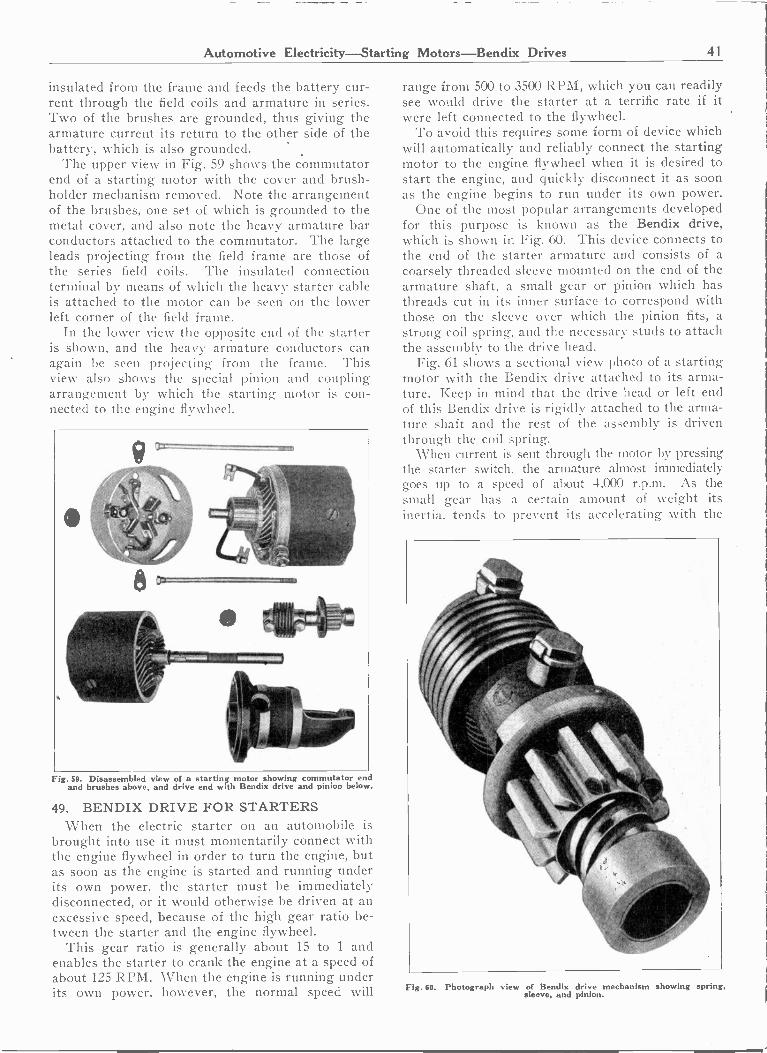
Automotive Electricity-Starting Motors-Bendix Drives 41
insulated from the frame and feeds the battery cur-rent through the field coils and armature in series.Two of the brushes are grounded, thus giving thearmature current its return to the other side of thebattery, which is also grounded.
The upper view in Fig. 59 shows the commutatorend of a starting motor with the cover and brush -holder mechanism removed. Note the arrangementof the brushes, one set of which is grounded to themetal cover, and also note the heavy armature barconductors attached to the commutator. The largeleads projecting from the field frame are those ofthe series field coils. The insulated connectionterminal by means of which the heavy starter cableis attached to the motor can be seen on the lowerleft corner of the field frame.
In the lower view the opposite end of the starteris shown, and the heavy armature conductors canagain be seen projecting from the frame. Thisview also shows the special pinion and couplingarrangement by which the starting motor is con-nected to the engine flywheel.
Fig. 59. Disassembled view of a starting motor showing commutator endand brushes above, and drive end with Bendix drive and pinion below.
49. BENDIX DRIVE FOR STARTERSWhen the electric starter on an automobile is
brought into use it must momentarily connect withthe engine flywheel in order to turn the engine, butas soon as the engine is started and running underits own power, the starter must be immediatelydisconnected, or it would otherwise be driven at anexcessive speed, because of the high gear ratio be-tween the starter and the engine flywheel.
This gear ratio is generally about 15 to 1 andenables the starter to crank the engine at a speed ofabout 125 RPM. When the engine is running underits own power, however, the normal speed will
range from 500 to 3500 RPM, which you can readilysee would drive the starter at a terrific rate if itwere left connected to the flywheel.
To avoid this requires some form of device whichwill automatically and reliably connect the startingmotor to the engine flywheel when it is desired tostart the engine, and quickly disconnect it as soonas the engine begins to run under its own power.
One of the most popular arrangements developedfor this purpose is known as the Bendix drive,which is shown in Fig. 60. This device connects tothe end of the starter armature and consists of acoarsely threaded sleeve mounted on the end of thearmature shaft, a small gear or pinion which hasthreads cut in its inner surface to correspond withthose on the sleeve over which the pinion fits, astrong coil spring, and the necessary studs to attachthe assembly to the drive head.
Fig. 61 shows a sectional view photo of a startingmotor with the Bendix drive attached to its arma-ture. Keep in mind that the drive head or left endof this Bendix drive is rigidly attached to the arma-ture shaft and the rest of the assembly is driventhrough the coil spring.
When current is sent through the motor by pressingthe starter switch, the armature almost immediatelygoes up to a speed of about 4,000 r.p.m. As thesmall gear has a certain amount of weight itsinertia, tends to prevent its accelerating with the
Fig. 60. Photograph view of Bendix drive mechanism showing spring,sleeve, and pinion.
1- -/ ol

42 Automotive Electricity-Electric Starters
Commutator Amty Armature Herielix Sptiog
Fig. 61. Sectional view of an automobile starting motor showing commu-tator and brushes on the left and Bendix drive on the right. Exam-ine this figure carefully while reading the explaining paragraphs.
motor, and as it is loose on the threaded sleeve it tendsto turn slower than the sleeve, which causes the threadsto force it outward to engage the teeth of the fly-wheel. The coil spring then absorbs the shock as themotor starts to crank the engine.
As soon as the engine starts to run under its ownpower the speed of the flywheel tends to exceed thatof the starter gear and causes it to revolve faster thanthe drive sleeve, so that the threads force the gear backtoward the starting motor and out of mesh with theflywheel teeth.
To avoid the possibility of the small pinion or gearrevolving and creeping along the threaded sleeve due tocar vibration and thus possibly engaging the flywheelwhen the engine is running, the gear has attachedto it a flange one side of which is much heavier thanthe other. This heavy side tends to hang down-ward and prevents the gear from revolving exceptwhen the starting motor operates it.
In addition to this weighted flange, an added pre-caution is provided in the form of a small stop pinwhich can be seen in the lower edge of the flange inFig. 61.
When the pinion gear is thrown to the idle positionthis little pin is forced by a light spring into a shallowgroove in the driving head, thus holding the gear inthis retarded position.
Two of the great advantages of the Bendix driveare its very simple construction and the fact that itallows the starting motor to come up to full speedbefore connecting it to the engine, thus giving themotor a tremendous "break away" or initial startingtorque to crank the engine.
50. MANUAL PINION SHIFTSAnother method that is quite commonly used for
engaging the starter pinion with the flywheel gear isknown as the manual shift. With this system thepinion is attached to the starter pedal by a lever ar-rangement which, during the first downward movementof the starter pedal shoves the pinion into meshwith the flywheel gear.
Further movement of the pedal operates the starterswitch, starting the motor and cranking the engine.Just as soon as the engine starts the foot should beremoved from the pedal to allow the strong spring
which returns the pedal to normal position to also with-draw the pinion from the flywheel gear.
Starters of this type generally also have in the piniona form of slipping clutch arrangement which will pre-vent the motof from rotating at excessive speeds incase the pinion should stick or jam in the meshedposition when the engine starts.
Fig. 62 shows a starter with the manual -type shiftmounted on the transmission of an engine and with asection of the flywheel casing cut away to show themanner in which the gears are meshed. Note attachedto the starter pedal the lever which first moves thesmall gear into place and then presses the starter switch,which is located on top of the motor.
Fig. 63 shows a starting switch of the foot -operatedtype for mounting in the floorboard of the car. Theconnections from the battery to the starting switch, andalso from the starting switch to the terminal of thestarting motor, are made with heavy stranded coppercable which is equipped with soldered lugs to securelow -resistance connections to the battery, switch, andmotor terminals.
It is very important to see that the lugs of this startercable are well soldered to the conductor, and that theyare securely tightened to all terminal connections. Whenyou consider that it is necessary for the 6 -volt batteryto send several hundred amperes through this circuit,you can readily see that the slightest amount of loose-ness in these terminal connections, or even a thin layerof dirt or corrosion at such terminals, would createenough resistance to greatly interfere with efficientstarter operation. Even a small fraction of an ohmwould cause too much voltage drop at the starter. Forexample, 1/50 of an ohm in a circuit carrying 200amperes would cause a voltage drop of 1/50 x 200, or
Fig. 62. This view shows method of meshing the starter pinion with theflywheel gear by means of the starter pedal which operates both the
gear and starter switch.
tis
'
r11-/.je00.°77.
VE1
o
'"520 -7s7 -',-ii
.1;44' -TNARgi--'WSW
mg" [® -
L

Automotive Electricity-Starter Troubles and Remedies 43
4 volts, thus leaving only 2 volts effective pressure atthe starter brushes.
For this same reason it is very important to keepthe contacts of the starting switch clean and in goodcondition and the switch properly operating, to avoidunnecessary resistance at this point. These contactssometimes become burned and pitted, due to makingand breaking the heavy current circuit, and they thenrequire scraping and polishing to provide a bright, newsurface.51. STARTER TROUBLES AND REMEDIES
Because of the very rugged electrical constructionof starting motors, troubles of an electrical nature arenot very often encountered within the motor itself.In most cases electrical troubles will be found to beat the commutator, brushes, brush holders, or leads.This fact should be kept well in mind by the troubleshooter or ignition service man.
When the starting motor gives trouble, it is gen-erally in the form of low cranking torque or completefailure of the motor. It should be kept in mind thatsatisfactory operation of the starter depends not onlyon the condition of the motor itself, but also on thecondition of the battery, connecting cables, and starterswitch, and one should carefully check each of theseitems before spending the time necessary to remove thestarting motor for thorough inspection or overhauling.52. LOW VOLTAGE AT STARTING MOTOR
If the starting motor fails to crank the engine prop-erly, a good test to determine the cause of the troubleis to switch on the lights and press the starter pedal.If the lights are extinguished when the starter switchis closed, the trouble is generally due to a loose ordirty connection in the starter circuit. Carefully checkthe battery terminals, cell connectors, and ground con-nection.
To help locate the trouble, hold the starter switchclosed for about one-half a minute and this will causethe loose connection to heat up so that it can be readilylocated by feeling along the different parts of thecircuit with the hand.
If the lights gradually dim down and go out whenthe starter switch is closed, this generally indicates adead battery. The battery should be removed from thecar and tested with a high rate discharge test, whichwill be explained later in the Battery Section.53. MECHANICAL TROUBLES
If, when the starter switch is closed, the lights dimslightly, but do not go out, it generally indicates mechan-ical trouble, which may be either in the engine or thestarter and is causing an overload on the starting motor.Crank the engine by hand to see if it is unusually tight,as might be the result of cold, heavy oil, tight bear-ings, etc.
Sometimes the starter pinion becomes jammed orlocked just as it starts to mesh with the flywheel gear.The pinion can usually be released by putting the carin high gear and rocking it back and forth to disengagethe pinion. If none of these troubles seem to bepresent, then remove the starting motor and check itfor a bent armature shaft or loose bearings.
Sometimes the starter may stick because of loosebearings which allow the armature to rub the polepieces and lock magnetically when current is applied.
If, when the starter switch is pressed, the lights donot dim at all, there is probably an open somewherein the starter circuit. This trouble will generally befound at the starter switch or at a loose cable connec-tion, or sometimes at brushes stuck in the brush holdersso that they do not rest upon the commutator. Anextremely dirty commutator or brushes may also givethis indication.
If the starting motor operates and spins at high speedwithout cranking the engine, it may be due to hardenedor gummed oil on the Bendix sleeve which preventsthe pinion from traveling into mesh with the flywheelgear. Washing off the threaded sleeve and parts witha brush and gasoline will generally cure this trouble.
Sometimes the Bendix spring or studs become brokenor there may be several teeth broken out of the flywheel,thus preventing the starter pinion from meshing at acertain point. If the starter uses a manual pinionshift, check carefully for disconnections or excessiveplay in the pedal rods or levers.
Fig. i3. Starter switch for mounting on the floorboard and connecting inseries with the lead from the battery to the starting motor.
If, when the starter is operated, a loud clashing orbanging noise occurs when the pinion meshes with theflywheel, check the bolts that hold the starter to theflywheel housing to see that they are tight. If thisdoesn't remedy the trouble, move the starter and exam-ine the teeth on the flywheel gear.
The edges of the teeth on both the flywheel andpinion gears are beveled to allow them to engage witheach other easily. If these teeth are badly burred, dueto rotating with only the entering edges meshed,noisy starter operation will result. This conditioncan only be remedied by replacing the gears.
Burred teeth are generally caused by improper align-ment of the pinion, which may be due to a bent arma-ture shaft, worn starter bearings, or loose starter.Clashing may also be caused at times by the threadedBendix sleeve sticking or "freezing" to the armatureshaft, and thus preventing the slight lateral movementwhich is necessary for silent gear meshing.
To correct this trouble, the Bendix drive should beremoved and disassembled and the armature shaft care-
'41.41....
4-0

44 Automotive Electricity-Starter Troubles-Generators
fully polished with fine emery cloth. Any rust shouldalso be removed from the inside of the Bendix sleeve.Then apply a little light oil and reassemble.
When the starting motor cranks the engine veryslowly, the trouble may be due to short circuits or high-resistance connections in the motor, or loose connec-tions and high resistance at the starter switch or cable.If the switch gets hot, remove it and look for burnedcontacts. Also inspect the switch for possible defectsin the insulation. Examine the starter cable carefullyfor loose connections or for damaged insulation whereit rubs against the car frame and may have becomegrounded.
The starting motor should be carefully checked forpoor brush contact, weak brush -spring tension, dirtycommutator or brushes, or unsoldered field or armatureconnections.
If the trouble is still not located, the armature, field,and brushes can be tested for grounds. A weak bat-tery may also cause the starter to crank the engine veryslowly.53. ELECTRICAL AND MECHANICAL
TROUBLES IN MOTORIf no trouble can be located at the battery, starting
switch, or cable and there appears to be electricaltrouble within the starting motor, it should be takenapart and carefully examined for both mechanical andelectrical defects, such as the following
Armature rubbing on the pole shoes, worn bearings,bent shaft, broken brushes or brushes stuck in thebrush holders, loose connections to the brushes or fieldcoils, grounded cable terminal, poor brush -spring ten-sion, loose connections between commutator bars andarmature leads due to solder having been melted andthrown out of the commutator risers, high resistancein the field circuit caused by solder melting and runningout of the joints between field coils, etc.
Always remember that anything that increases theresistance of the motor or its circuit will greatly de-crease its torque. The mistake that is sometimes madeby inexperienced or untrained automobile service menis that of replacing worn starter brushes with brushesof the wrong grade or material.
In order to be of sufficiently low resistance, thebrushes for starting motors are made of carbon andpowdered copper, the copper content being the greaterportion of the material used in these brushes. If thesebrushes are replaced with ordinary carbon or carbongraphite brushes, their resistance will be altogether toohigh for use on such heavy currents at low voltage.
Sometimes wrong brushes of this type become red-hot when the starting motor circuit is closed, but theywill not allow enough current to flow to start theengine.
You are already familiar with the methods of test-ing field coils or armature windings for grounds, shorts,opens, etc., as covered in the Sections on ArmatureWinding and Motor Repairs.
An ordinary 110 -volt test lamp can be used veryconveniently for checking for these faults on startingmotors. The brush holders should also be checked to
see that those which are supposed to be insulated havenot become grounded to the starting motor frame.
After a starting motor has been repaired and over-hauled it can be thoroughly tested before it is replacedon the car by means of a regular garage test bench suchas is used in most medium and large -sized garages orautomotive electrical service stations.
On these benches the starting motor is securelyclamped in a special vise and a spring scale and leverarrangement are attached to the shaft to measure itstorque when battery voltage is applied.
While in the Automotive Department of your shopcourse, be sure to get plenty of actual practice in over-hauling, repairing, and testing starting motors, and inthe use of test bench equipment.
54. AUTOMOTIVE GENERATORSAs stated in an earlier article in this section, the
generator is a very important piece of the electricalequipment on a modern automobile. With the extensiveuse of electric current for lights, ignition, horn, startingmotor, and various other purposes, any ordinary -sizedbattery would soon become discharged if there were nomeans for supplying it with current.
The length of the battery discharge could, of course,be prolonged by using batteries of larger sizes, but asthis would add considerable weight and additional ex-pense, it is much more practical to equip each car witha small low -voltage D. C. generator to keep the batterycharged, and also to supply the current for varioususes and prevent drain on the battery when the engineis running at normal speed.
Fig. 64. Photograph views of two types of automobile generators. Notethe metal band on the left end of each generator which can be re-moved for access to the brushes and commutator. Also note thecut-out mounted on top of the generator.
r
:
e

Automotive Electricity-Generators-Voltage Regulation 45
Fig. 65. Side view of a six -cylinder Nash engine showing the location of the starting motor, generator, double ignition distributor, and fuelpump. Note the generator driving belt which drives both the generator and fan.
For this purpose a small shunt-wound D. C. gen-erator is connected to the engine by means of a chain,belt, or gear, and is driven at a speed of about one anda half times engine speed, producing from 6 to 8 voltswithin the normal speed range of the engine.
Fig. 64 shows two very common types of automobilegenerators, and Fig. 65 shows a generator attached toa bracket and mounted upon the engine at the right-hand end. In this figure you will note the 'V" beltused to drive the generator and fan.
The general construction and operating principles ofD. C. generators have been thoroughly covered in theprevious section on D. C. power equipment, and theprinciples of automobile generators are very much thesame. Because of the peculiar conditions under whichthey operate, however, there are certain special featuresin their design that are very important and interesting toconsider.
For example, a generator must be capable of rotatingat very high speeds without injury, as it may often berevolved at speeds of 6,000 r.p.m. or over. Anotherspecial feature is the very interesting voltage control,which has been developed to enable the generator toproduce high enough voltage to charge the battery andsupply current when the car is operating at compara-tively low speeds and yet prevent the generator fromdeveloping excessive voltage and charging currents athigh speeds. When we consider that it is desired tohave the generator commence charging the battery at aspeed of about 12 miles per hour and yet not chargeexcessively or develop too high voltage at speeds of
even 60 or 70 miles an hour, this voltage regulationis quite an accomplishment.
Another feature of the automobile generator is theconvenient means provided for adjusting or changingthe charging rate so that it can be set to suit variousdriving conditions.
55. THIRD BRUSH REGULATIONOne of the most commonly used and popular types
of automobile generators which fulfills the above re-quirements is known as the "third brush" type, becauseit uses a small third or auxiliary brush to regulate thevoltage at different speeds.
This brush is connected to one end of the field wind-ing and is placed in such a position on the commutatorthat it tends to decrease the field voltage and currentwhen the generator speed increases, and so preventsthe armature voltage and current from rising abovethe limit for which the brush is set.
The location and connection of this third brush isshown in Fig. 66.
You have already learned in an earlier section onD. C. motors and generators that when the armaturewindings are carrying current there is set up aroundthem a strong magnetic field which tends to distort thelines from the field poles, and cause the pole flux toshift around the pole faces in the direction of rotation.This armature reaction results in weakening the fluxat one pole tip and strengthening it at the other, asshown at Fig. 66.
In this diagram the coils A to G are under one fieldpole and will have generated in them a voltage propor-

46 Automotive Electricity-Third Brush-Charging Rate Adjustment
Fig. 66. Diagram showing the armature reaction, field distortion, andprinciples of third brush voltage regulation on an automobile gen-erator.
tional to the speed at which they are rotated and to thestrength of the magnetic field of the generator. As-suming that each coil generates 1 volt, the voltagebetween adjacent commutator bars will be 1 volt;and the voltage between the main brushes will be thesum of the voltages generated in the separate coils inone side of the winding, or in this case 7 volts.
Note that the two sides of the armature windingform two parallel paths from the negative to positivebrush. With a pressure of 1 volt between bars, thevoltage applied to the field coils which are connectedbetween the negative brush and third brush will be 5volts.
This voltage doesn't remain constant, but varies withthe shifting of the field flux due to the change ofcurrent load in the armature conductors. For example,if the armature develops a certain voltage and deliversa current of 10 amperes at a speed of about 1,800r.p.m., then if the speed is increased the voltage andcurrent will tend to increase.
A slight increase in the armature current increasesthe field distortion, moving the more dense field fluxfarther toward the pole tips. This weakens the fieldthrough which coils A, B, C, D, and E are movingthus reducing the voltage applied to the field, cuttingdown the total generator field strength, and tendingto prevent the voltage at the main brushes from risingin proportion with the increase of speed.
In actual practice this third brush method of voltageregulation allows the charging rate to gradually increaseup to generator speeds of about 1,800 at whichpoint the correct relation between armature current andfield voltage is obtained. From this point the chargingrate gradually falls off as the speed is increased abovethis limit. This is generally a desirable feature, par-ticularly in the summer time, when the car may oftenbe operated for long periods at high speeds, as it pro-
tects the battery from being overcharged and the gen-erator from overheating.
As the voltage applied to the field varies immediatelywith any change of generator speed and armature cur-rent, resulting in a change of field distortion, thisregulation is entirely automatic and maintains a fairlysteady voltage even with sudden variations in the enginespeed.
56. ADJUSTING CHARGING RATETo adjust the charging rate of a generator of this
type, all that is necessary is to slightly shift the positionof the third brush on the commutator to include moreor less bars between it and the negative brush.
You can readily see that if the third brush in Fig. 66were shifted farther to the right it would include morearmature coils in the field circuit and supply highervoltage to the field, thus causing the generator todevelop higher armature voltage at the main brushesand, increase the charging rate.
On the other hand, if the brush were shifted to theleft to cut out part of the winding between it and thenegative brush, there would be less voltage applied tothe field coils, and the generator voltage and chargingrate would be decreased.
The third brush is generally arranged with a setscrew which normally holds it securely in one position,but which can be loosened to allow the brush to beshifted, either by lightly tapping against the holderwith a screwdriver or by the adjustment of an auxiliaryshifting screw. This provides a convenient method ofincreasing the charging rate during winter monthswhen the engine starts hard, due to cold, stiff oil andtherefore requires considerably more starting current.This is also the season when the daylight hours are
Fig. 67. Disassembled view of an automobile generator showing commu-tator and brushes above, drive end of generator in the center, and
small views of field coils and armature below.
r.p.m., 111tr060-4111111""

Automotive Electricity-Generators-Cut-Outs 47
shorter and the headlights are used a great deal moreon an average.
In the summer time, to prevent overcharging thebattery, the generator charging rate should be cut downby adjusting the third brush. This is particularly truewhen the car is being used on long trips at high speeds,as the battery would otherwise be overcharged andoverheated, and the generator would also tend to over-heat due to the continuous high operating currentthrough its armature.
It is important to know by merely looking at thegenerator in which direction to shift the third brush.To increase the charging rate, the brush should beshifted in the direction of rotation of the commuta-tor, and to decrease the charging rate the brushshould be shifted in the direction opposite to that ofcommutator rotation.
The upper view in Fig. 67 shows the commutatorend of an automobile generator with the end -plate andbrush rigging removed. The two large brushes placedat right angles to each other are the main brushes andthe smaller brush is the third brush, or voltage regu-lating brush.
The center view in this figure shows the oppositeend of the generator, opened up to show the end of thearmature winding and the drive shaft by which the unitis coupled to the engine.
At the bottom of this figure are shown four fieldcoils and an armature completely removed from thegenerator frame.
Fig. 68 shows a set of curves which indicate thevariations in voltage and current at different enginespeeds and for generators operating both cold and hot.Note the difference in the operating current due to theincreased resistance of the generator windings afterthe unit has been operating for some time and iswarmed up.
V'WI!416
,IjIs,,,.4 ,az
i0
ti aa 6
Z4
'C,. a
1 °
1 01.R.h
5
S
:
4.5 t"
3
,u
V'''......."..................
--4...,.....a
10 E0 30 40 SO
MILES PER HOUR
Fig. 68. These curves show the variation in generator voltage andcharging current with changes of car speed and variations in gen-erator temperature.
57. GENERATOR CUT-OUTSIn order to prevent the battery discharging back
through the generator when the engine speed falls toolow to allow the generator to develop a voltage equalto that of the battery, a device known as a reversecurrent cut-out is commonly used.
This device is simply a magnetically operated switchor relay equipped with both a series and shunt windingand a set of contacts, as shown in Fig. 69. The cut-outis generally mounted on top of the generator, as shownin Fig. 69 and also on the photographic view of thelower generator in Fig. 64.
Fig. 69. This diagram shows the connection of an automobile generatorand complete charging circuit, including the cut-out, ammeter, batteryand field protective cevices.
The shunt winding consists of a good many turns offine wire and is connected directly across the maingenerator brushes, as can be noted by carefully tracingthe circuit from the top brush of the generator inFig. 69 up through the cut-out frame and shunt coil toground, by which it returns to the lower brush of thegenerator. This means that the strength of the shuntcoil will always be proportional to the voltage out-put of the generator.
When the generator voltage rises to about 7 voltsthe shunt coil becomes strong enough to magnetize thecore and attract the armature, closing the contacts inthe charging circuits through the ammeter to the bat-tery. This charging current flows through the seriescoil consisting of a few turns of heavy wire, and thiscoil is wound so that the current flows in the samedirection as through the shunt coil, thus adding themagnetic strength of the series coil to that of the shuntcoil and holding the contacts firmly closed.
Whenever the generator speed falls below a certainvalue, its voltage drops below that of the battery andthe battery commences to discharge back through it.This discharge current flowing through the series coilin the opposite direction sets up a magnetic field whichopposes that of the shunt coil and demagnetizes thecore, allowing the spring to pull the armature back andopen the contacts.
A reverse current or discharge current of not over2 amperes should be sufficient to release the cut-outcontacts. These cut-outs not only prevent the batteryfrom discharging through the generator at low speeds,but also prevent the generator from being overheatedand burned out in case the engine was stopped and thebattery discharged a heavy flow of current through thegenerator armature in an attempt to motorize the gen-erator, which, of course, is connected rigidly to theengine and cannot be turned because of insufficienttorque to rotate the engine.
Fig. 70 shows two types of cut-outs, one with thecover removed showing the coil and contacts.
By referring to Fig. 69 again you will note that theammeter is connected in series with the generator andthe battery so that it will register the current flowingto the battery by a movement of the needle over theside of the scale marked "Charge." This instrument
0
a
,
IMMENVAIIMINEMEMIIIIIMMENIMINMEN
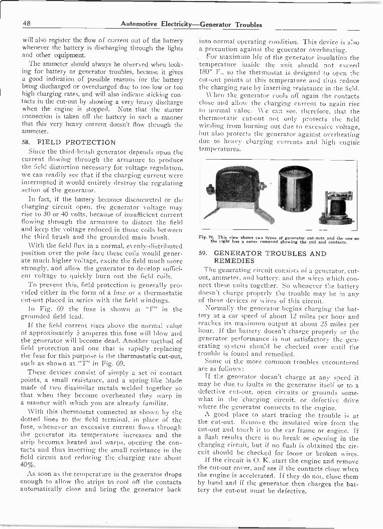
48 Automotive Electricity-Generator Troubles
will also register the flow of current out of the batterywhenever the battery is discharging through the lightsand other equipment.
The ammeter should always be observed when look-ing for battery or generator troubles, because it givesa good indication of possible reasons for the batterybeing discharged or overcharged due to too low or toohigh charging rates, and will also indicate sticking con-tacts in the cut-out by showing a very heavy dischargewhen the engine is stopped. Note that the starterconnection is taken off the battery in such a mannerthat this very heavy current doesn't flow through theammeter.
58. FIELD PROTECTIONSince the third -brush generator depends upon the
current flowing through the armature to producethe field distortion necessary for voltage regulation,we can readily see that if the charging current wereinterrupted it would entirely destroy the regulatingaction of the generator.
In fact, if the battery becomes disconnected or thecharging circuit open, the generator voltage mayrise to 30 or 40 volts, because of insufficient currentflowing through the armature to distort the fieldand keep the voltage reduced in those coils betweenthe third brush and the grounded main brush.
With the field flux in a normal, evenly -distributedposition over the pole face these coils would gener-ate much higher voltage, excite the field much morestrongly, and allow the generator to develop suffici-ent voltage to quickly burn out the field coils.
To prevent this, field protection is generally pro-vided either in the form of a fuse or a thermostaticcut-out placed in series with the field windings.
In Fig. 69 the fuse is shown at "F" in thegrounded field lead.
If the field current rises above the normal valueof approximately 5 amperes this fuse will blow andthe generator will become dead. Another method offield protection and one that is rapidly replacingthe fuse for this purpose is the thermostatic cut-out,such as shown at "T" in Fig. 69.
These devices consist of simply a set of contactpoints, a small resistance, and a spring -like blademade of two dissimilar metals welded together sothat when they become overheated they warp ina manner with which you are already familiar.
With this thermostat connected as shown by thedotted lines to the field terminal, in place of thefuse, whenever an excessive current flows throughthe generator its temperature increases and thestrip becomes heated and warps, opening the con-tacts and thus inserting the small resistance in thefield circuit and reducing the charging rate about40%.
As soon as the temperature in the generator dropsenough to allow the strips to cool off the contactsautomatically close and bring the generator back
into normal operating condition. This device is alsoa precaution against the generator overheating.
For maximum life of the generator insulation thetemperature inside the unit should not exceed180° F., so the thermostat is designed to open thecut-out points at this temperature and thus reducethe charging rate by inserting resistance in the field.
When the generator cools off again the contactsclose and allow the charging current to again riseto normal value. We can see, therefore, that thethermostatic cut-out not only protects the fieldwinding from burning out due to excessive voltage,but also protects the generator against overheatingdue to heavy charging currents and high engirietemperatures.
Fig. 70. This view shows two types of generator cut-outs and the one onthe right has a cover removed showing the coil and contacts.
59. GENERATOR TROUBLES ANDREMEDIES
The generating circuit consists of a generator, cut-out, ammeter, and battery, and the wires which con-nect these units together. So whenever the batterydoesn't charge properly the trouble may be in anyof these devices or wires of this circuit.
Normally the generator begins charging the bat-tery at a car speed of about 12 miles per hour andreaches its maximum output at about 25 miles perhour. If the battery doesn't charge properly or thegenerator performance is not satisfactory the gen-erating system should be checked over until thetrouble is found and remedied.
Some of the more common troubles encounteredare as follows:
If the generator doesn't charge at any speed itmay be due to faults in the generator itself or to adefective cut-out, open circuits or grounds some-what in the charging circuit, or defective drivewhere the generator connects to the engine.
A good place to start tracing the trouble is atthe cut-out. Remove the insulated wire from thecut-out and touch it to the car frame or engine. Ifa flash results there is no break or opening in thecharging circuit, but if no flash is obtained the cir-cuit should be checked for loose or broken wires.
If the circuit is 0. K. start the engine and removethe cut-out cover, and see if the contacts close whenthe engine is accelerated. If they do not, close themby hand and if the generator then charges the bat-tery the cut-out must be defective.

Automotive Electricity-Generator Troubles 49
Quite often the shunt winding will be found tobe burned out and in this case the cut-out shouldbe replaced with a new one.
If with the engine running at moderate speed thegenerator doesn't charge after the cut-out contactsare closed by hand remove the cut-out from thecircuit and connect the generator directly to thebattery. If the generator now charges there mustbe a ground in the cut-out and this unit should bereplaced or repaired.
Sometimes the cut-out contacts may be foundburned or dirty so that they do not close the charg-ing circuit to the battery. In this case they shouldbe carefully cleaned with fine sandpaper.
A defective field protection device may also pre-vent the generator from charging. If a fuse is usedfor this protection see whether or not it is blown,and if not see that it is making good contact withthe fuse clips.
If the generator is equipped with a thermostatexamine this device carefully for dirty or pittedcontacts or bent spring blade. If the thermostat isdefective it should be adjusted or replaced.
If no trouble can be located in any of the abovedevices or in the wiring of the generator circuitthen the fault is likely to be in the generator itselfand it should be removed, and carefully tested.
If the generator charges but at a very low rateit may be due to a loose drive belt, poor brush con-tact, high resistance in the field circuit because ofloose or dirty connections, improper setting of thethird brush, or partial short circuits in the wind-ing. The remedies for each of these troubles canbe clearly seen without further explanation.
If the generator charges at too high a rate whenthe car is run at high speed this may be caused bya grounded third brush; or, in case the generatorhas been recently repaired, the field leads may havebeen connected wrong. Where one end of the fieldis connected to the ungrounded main brush thegrounding of the third brush will cause the gen-erator to operate as a straight shunt-wound ma-chine and the regulating action of the third brushis eliminated.
If the generator charges when the car operatesat low speeds but the charging current falls to zeroat high speeds, this is usually the result of poorbrush contact, which may be caused by burned orglazed commutator surface, commutator out ofround, high mica, loose bearings allowing the com-mutator to vibrate, weak brush -spring tension, wornor dirty brushes, or brushes stuck in the holders.
If the commutator is out of round or has a veryrough surface it should be turned down in a latheand the mica should then be carefully undercut. Thebrushes should be sanded in, as explained in theD. C. Motor and Generator Sections, to see thattheir faces properly fit the commutator and are cleanand free from gum or dirt.
Be careful to see that the brush springs are atthe proper tension and that the brushes do notstick in the holders.
If the generator overheats badly it may be dueto shorted armature coils, or to the armature lam-inations having been burred together by rubbingon the pole faces, or by rough handling while beingrepaired.
Burred laminations promote eddy currents whichoverheat the core and the trouble can be correctedby taking a very light coat off from the core in alathe or by replacing the armature.
A loose connection in the charging circuit causinghigh field voltage will also result in the generatoroverheating; and wrong setting of the third brushallowing an excessive charging rate may be an-other cause.
If the generator voltage is too high and causesthe lights to flare or burn out this is generally dueto loose or dirty connections in the charging cir-cuit. High resistance in this circuit prevents thenormal flow of current through the armature of thegenerator and thereby prevents field distortion andthe voltage regulating action of the third brush. Soan open circuit or loose connection at the battery,ammeter, or anywhere in the generating circuit willcause excessive voltage and may result in a burnedout field winding if it is not quickly corrected. Insuch cases all connections should be carefullycleaned and tightened.
When the generator brushes squeal during opera-tion at certain speeds or at all speeds this may beremedied by cleaning the commutator and sandingoff the faces of the brushes; or, in case it is causedby hard brushes, by boiling them for a few minutes'in paraffin wax. If the trouble cannot be correctedin this manner replace the brushes with those rec-ommended by the manufacurer.
When testing a generator for internal troublesfirst take the machine apart and carefully examineit for mechanical defects or any electrical troubleswhich can be noted. Then test the armature foropens, shorts, or grounds, as previously explainedin the section on Armature Winding and Testing.
Next test the fields for the same troubles. Testeach of the brush holders for possible grounds dueto defective insulation, check the commutator tosee that its surface is clean, that there is no highmica, and no short circuited bars. Check the brushesto see that they are all properly fitted, have theright spring tension, and move freely in the holders.
Replace any defective parts before reassemblingthe generator.
60. LIGHTING EQUIPMENTThe lights are a very important part of every
modern automobile, as it is impossible to drivesafely on unlighted country highways without twogood headlights; and these headlights provide agreat safety feature by indicating the position and

50 Automotive Electricity-Lighting Equipment
approximate speed of an approaching car even onlighted streets and highways.
The headlights of a modern automobile shouldilluminate the road surface for several hundred feetahead of the car, in order to enable the driver tosee people or obstructions in the road in time tobring the car to a full stop from the high speedsat which modern cars are commonly operated.
In order to avoid "blinding" an approachingdriver, the headlights should throw definite beamsof light which can be kept down on the road sur-face and below the level of the eyes of other drivers.
Electric lights meet these requirements verynicely by supplying a concentrated beam of highcandle power that can be quickly and easily focusedand controlled. Therefore, electric lighting is nowused without exception on all modern automobiles.
The headlights are generally provided with a dim-ming device which enables them to be dimmed ortheir beams to be dropped lower when meeting an-other car, and then brightened or the beams raisedfor vision farther ahead on a dark country road.
In addition to the headlights, most cars are equip-ped with cowl lights, tail light, stop light, dashlight, and dome light, while some have additionalsmall convenience lights at various places in the car.
Cowl lights are small lights located one on eachside of the body of the car just in front of the windshield. These lights can be left on when the car isparked and they serve to show the position of thecar to another driver. They are much smaller andrequire a great deal less battery current than wouldbe used if the headlights were left on. Cowl lightscan also be used for driving the car on well lightedstreets or roadways.
A tail light is very essential to indicate the rearof the car to a driver approaching from behind andalso to illuminate the license plate as required bystate laws. The tail light should always be kept ingood condition so that it shows a distinct red lightto the rear of the car, as this affords a great amountof protection from rear end collisions both whenthe car is in operation and when parked. A carshould never be operated or left parked without agood tail light.
The stop light is a more recently developed lightwhich goes on when the brake is pressed and indi-cates to a following driver that the car ahead isabout to slow down or stop. Stop lights also afforda great amount of protection to the rear ends ofautomobiles; and, for reasons of one's own safetyas well as courtesy to fellow drivers, cars shouldnever be operated without a good stop light.
The purpose of the dash light or lights is toilluminate the various instruments on the dash orinstrument board of the automobile, enabling thedriver to see his speedometer and the meters andinstruments which indicate various conditions, suchas engine temperature, fuel level, oil pressurecharging rate, etc.
Dome lights illuminate the interior of the carand are particularly convenient when getting in andout of the car at night, or whenever one desires tosee within the interior of the car. Dome lights,however, should not be left on when a car is drivenalong a dark highway as they interfere with theview of the road ahead.
All automobile lamps are designed to operate atlow voltage, generally six volts, and are connectedto the battery through the ammeter and conveni-ently located switches.
The bulbs for the various lights are designedwith filaments of various resistance and wattagesaccording to the amount of light required. Theheadlights, of course, are the larger and the variousother lights use smaller bulbs.
A single -wire system is now in general use forthe wiring of automobile lights, and the other ter-minal of each light socket is grounded so that thecurrent returns through the car frame to thegrounded terminal of the battery. This arrange-ment greatly simplifies and reduces the cost of wir-ing systems, and also lessens the possibilities oftrouble in the circuits.
Many people are inclined to operate their carswith one or more defective lights because they donot realize the importance of lights as a safetyfeature, or do not realize how easily and cheaplylights can all be kept in good condition. It is asimple matter for the experienced or trained serviceman to quickly locate and repair almost any troublein the lighting system, and every attempt shouldbe made to encourage customers to have defectivelights repaired or replaced immediately and keepthem in good condition at all times.61. HEADLIGHTS
Headlights, as previously mentioned, are themost important of any lights on the automobile.Headlights are carefully designed to project thelight beams on the roadway in the proper mannerto give the driver a good view of its surface somedistance ahead and to avoid glare in the eyes ofapproaching drivers.
Each headlight consists of the following im-portant parts: Electric light bulb which suppliesthe light ; reflector which controls and concentratesthe light beam ; lamp housing in which the bulb andreflector are supported; bulb adjusting devices usedto focus the light; front glass or lens ; and lampstandard or bracket which attaches the headlightto the car.
Fig. 71 is a diagram showing a sectional view ofa headlight and in which each of the above partscan be noted.
The lamp housings are made in various styles andshapes to fit the design of the car, and the reflectorsare made of silvered metal of the proper shape togather all the light rays thrown backward and side-wise from the bulb and concentrate them forwardin one beam upon the road surface.

Automotive Electricity-Headlights, Dimming 51
-RIM
- --FRONT GLASS OR LENS
- --LAMP SOCKET ADJUSTMENT
- BASE CONTACT
- - LOCK PIN
- - FILAMENT
- BASE
- LAmP SOCKET
- REFLECTOR
LAMP MOUSING
BRACKET
Fig. 71. Diagram showing the construction of a common type of auto-mobile headlight. Note that the lamp socket is adjustable for focus-ing the light rays properly with the reflector.
Headlight lenses are of various types, some hav-ing specially cut or ground glass with ribs or cor-rugations to aid in directing or diffusing the lightas desired.
The lamp adjusting device allows the bulb to bemoved either forward or backward in the socket toadjust the focus of the light beam and make itbroader or narrower.
Automobile headlight bulbs are constructed quitesimilarly to regular incandescent light bulbs, withwhich you are already familiar, except that theirfilaments are designed for lower voltage and aretherefore made of lower resistance and to takeheavier currents in order to produce the desiredwattage. These bulbs have a concentrated filamentwhich produces the light from a source of a verysmall area, thus making it easy to focus and directwith the reflector and lens.
The bulbs are small, ranging in diameter fromabout an inch to an inch and a half, and are securedto a metal base or ferrule by means of which theyare held into the socket and connected to the elec-tric circuit.
Some headlight bulbs are of the single filamenttype but most of those used on recent makes ofcars are of the double filament type, having twoseparate filaments located one above the other andeither of which can be turned on at will by thelight switch.
One filament is used for directing a bright beama long distance down the road, while the other isused for directing a beam of less brilliancy slightlydownward and at a spot on the road closer to thefront of the car. This latter filament is used whenmeeting another driver and helps to further reducethe blinding glare in his eyes.
On single filament lamps one end of the filamentis connected to the outer metal ferrule of the lampbase which is grounded to the lamp housing whenthe lamp is placed in the socket. The other filament
lead is insulated and connected to a small terminalin the base of the socket by which it makes contactwith a spring terminal attached to the insulatedlight wire leading from the battery and switch tothe lamps.
Double filament bulbs have one end of each fila-ment grounded to the ferrule and the other twoends brought to separate insulated contacts in thelamp base.
On the left in Fig. 72 are shown two headlightbulbs, one of the double filament and one of thesingle filament type; and on the right are showntwo of the smaller bulbs such as are used for dashlights, tail lights, etc.
62. DIMMING OF HEADLIGHTSAs mentioned before, it is desirable to provide
some means of dimming or dropping the headlightbeams when meeting another driver, and thusavoiding throwing in his eyes a glaring light whichwould make it impossible for him to see the roador the exact location of the approaching car.
There are in general use two common methodsof dimming; one by using a resistance that is cutin series with single filament bulbs, and the otherand more popular method of using double filamentbulbs.
Fig. 72. Several types of doub and single filament bulbs used for head-lights and other lights on automobiles.
Fig. 73-A shows a diagram of the wiring for head-lights using the resistance method. When theswitch is at the left in the position shown, theresistance is in series with the bulb filaments andreduces their current and light output. When theswitch is moved to the right the resistance is cutout, bringing the bulbs up to full brilliancy.
In Fig. 73-B is shown the wiring for the double -filament type lamps. When the switch is on the leftcontact the lower wattage upper filaments of thelamp are in use. These filaments being locatedsomewhat above the center of the reflector causethe beam to be thrown downward and closer tothe front of the car. When the switch is thrownto the right-hand contact the heavier wattage lowerfilaments are in use, and as these filaments are inthe center of the reflector their light beams arethrown slightly higher and farther ahead along theroad.
The smaller or dimmer filament is generally of21 candle power, (C.P.) and the larger filament ormain headlight filament of 32 C.P.
-
-
-
- -
-
-

52 Automotive Electricity-Lighting Switches
Fig. 73. A. Diagram showing resistance method of headlight dimming.B. Double filament method of dimming or "dropping" headlightbeams.
The light switch for turning headlights on andoff and for dimming them was formerly located onthe dash of automobiles, but on modern cars it isgenerally located either on the steering wheel orcolumn; or a foot switch is placed near the clutchpedal. Either of these arrangements is much moreconvenient than the dash switch for reaching theswitch and dimming the lights when necessary.63. LIGHTING SWITCHES
The upper view in Fig. 74 shows several typesof operating levers for lighting switches and beloware shown the switch contacts mounted on the in-sulating base of the switch. When the switch leversare mounted on the dash the switch mechanism andcontacts are generally mounted directly behindthem. When the switch levers are mounted on thetop of the steering column the switch mechanismis generally mounted on the lower end of the columnand operated by a long rod which runs from thelever down through the column.
The switch -lever positions are generally markedaccording to the lights that are turned on in eachposition, such as cowl or side, bright or head, dim,off, on, etc. The stationary contacts on the switchbases are also usually marked, so that it is an easymatter to connect the various light wires to theswitch.
One of the contacts is connected directly to thebattery. When the switch is turned on the contactfingers slide around to close circuits from the bat-tery contact to the various sets of lights, accordingto the position the switch is placed in.
In case the switch contacts are not marked thebattery terminal can be located by testing with apiece of wire grounded to the frame of the car.The battery terminal is the one which will give aflash when touched with this grounded wire andwith the switch in the off position.
Now connect one end of the test wire to the bat-tery terminal and try out the remaining contactswith the other end, and note the results. When theend of the wire is touched to the headlight contactthe headlights will light; and if the tail light con-tact is touched this lamp will light, etc., and inthis manner the different terminals can be quicklyand easily located.
If a switch has been removed for repairs and allthe wires are disconnected they can be tested outand connected up as follows:
Touch to the car frame each of the wires thatconnect to the switch until one is found whichgives a flash. That is the live wire from the batteryand should be connected to the battery contact onthe switch. Touch the remaining wires on the bat-tery contact until the tail light wire is found by thetail light burning when a certain wire is touched.Then connect this wire to the contact marked "taillight," or to the one which will give a light when theswitch is on in any position. The tail light is gen-erally switched on when any of the other lightsare on.
Fig. 74. At the top of this figure are shown several types of lightswitches and below are shown the backs of the switches with theirvarious contacts for the different light circuits.
The wires to the other lights can be found in thesame manner and connected to the properly markedswitch contacts or to the contacts which will givea light when the switch lever is in the proper posi-tion for whichever light is being connected.
The stop light is generally controlled by a smallswitch located under the floorboards of the car andoperated by a wire and spring attached to the brakepedal.
Dome lights and other convenience lights aroundthe car are generally operated by small snap or pushbutton switches located in convenient places.
The dash light on modern cars is generallyswitched on whenever the headlights or other driv-ing lights are on. In some cases it is left off whenonly the parking lights are on, and in other cases
vv.
A
B
Automotive Electricity-Lighting Troubles 53
it is equipped with a special snap switch of its ownso that it can be turned off when desired.
Dash lights are sometimes connected in serieswith the tail light, so they will go out and warnthe driver any time the tail light burns out.64. TROUBLES IN LIGHTING SYSTEMS
The electric wiring on an automobile is com-paratively simple and the wires are usually partlyvisible, so generally no complicated testing orelaborate test instruments are required to check thesystem for such common troubles as opens, shorts,grounds, loose connections, etc.
A simple low -voltage test lamp made up with asix -volt bulb or a low reading voltmeter is oftenvery convenient. However, in the majority of casesa screw driver and a short piece of test wire areall that is necessary to locate troubles.
Some of the more common troubles and remediesof automobile lights are covered in the followingparagraphs.
If all of the lights fail to light when the switchis turned on, check to see if the main fuse is burnedout, and if it is not, see that it is making good con-tact with the fuse clips.
If a circuit breaker is used, check to see if thecontacts are dirty or pitted, or if the plunger issticking.
Test with a short test wire from the battery ter-minal on the switch to ground or to some metal partof the car, and if a flash is obtained this indicatesthat battery current is reaching the switch and thatthe trouble is very likely in the switch itself. Byremoving and checking the switch the loose, dirty,or bent contacts can generally be located.
If no flash results when the battery contact onthe switch is grounded with the test wire, checkfor a broken wire between the switch and batteryor for a burned out ammeter.
Failure of all lights might also be caused by allof the bulbs being burned out due to a surge ofhigh voltage from the generator, but this is veryunlikely as all the lights will not usually burn outat once and such a surge would be noticeable ifthey did.
If at any time during the operation of the carthe lights all brighten up considerably, shut off theengine immediately and check for a loose connec-tion in the generator charging circuit, since thisis the most probable cause of an increase in gen-erator voltage as previously explained.65. HEADLIGHTS FAIL
If the headlights do not light up but all of theother lights do, the trouble will be in the headlightbulbs or the headlight circuit somewhere.
If the lighting system is one in which each ofthe light circuits is separately fused, examine theheadlight fuses first. Next remove the insulatedplug which leads to the lamp housing and connectsto the bulb socket, and touch this plug to the backof the lamp housing or car frame. If no flash occurs
it indicates a break between the headlight and thebattery, probably in the switch but possibly in thewire.
If no flash is obtained when this terminal isgrounded, test next with a wire from the headlightcontact on the switch to ground, and if no flashoccurs here connect the test wire from the batteryterminal on the switch to the headlight contact. Ifthe lights then burn the trouble is proved to be inthe switch.
Remove the switch and check for dirty, burned,or pitted contacts and switch fingers. Also see ifthe contact fingers have lost their spring tensiondue to overheating. The switch lever must be inthe headlight position while making these tests.
If a flash was seen when the insulated headlight plugwas touched to the car frame, the trouble must be in theheadlight. Remove the lens and examine the bulb ortest it, and if it is burned out, replace it. If the bulbis all right, the trouble may be due to the fact that thecontact on the insulated plug is not making good con-tact to the bulb. It may also be caused by rust formingbetween the reflector-in which one end of the lightfilament is grounded-and the lamp housing, or Fe-tween the lamp housing and the car frame.
Rusty or dirty connections at these points mean anopen or high -resistance circuit between the groundedterminal and the battery.
To test for an open or high -resistance connectionbetween the reflector and the grounded terminal of thebattery, place one end of the test wire on the wirewhich carries the current to the headlights and touchthe other end to the reflector. If no flash is obtained,check for poor contact between the lamp contacts andhousing, or between the housing and car frame.
The various other lighting circuits can be tested outin the same manner as outlined for headlights. Checkto see if the current is carried through the wire all theway up to the light, and then test for burned -out bulbsand poor grounds between the lamp housing or socketand car frame.66. FLICKERING AND FLARING OF
LIGHTSHeadlights and other lights are sometimes caused to
flicker by loose connections in the lighting circuits, andvery often this trouble is found to be at the insulatedplug which connects to the lamp housings.
The small springs which connect the plug and bulbterminals together either become weak or stuck, orburned and dirty. Sometimes it is only a small amountof corrosion that is responsible for high resistance inthe circuit and causes the lights to dim or flicker occa-sionally.
In this case the trouble may be remedied by merelyworking the plug back and forth in its socket to ruboff the corrosion and brighten the contacts. When thetrouble is due to weak contact springs, these springsmay be stretched out or the trouble may be remediedby adding a small drop of solder to the bulb contacts,thereby increasing the pressure and tension on thespring contacts.

54 Automotive Electricity-Lighting Circuit Troubles
If the flickering is not due to trouble in the lampsor at the plug connections, then check over the entirecircuit, cleaning and tightening any dirty or loose con-nections; and, if it is necessary, check the switch forloose or burned contacts.
As previously mentioned, flaring lights are generallycaused by loose connections in the generator circuit ordefects in the generator. In such cases all connectionsin the generator and charging circuit should first becarefully cleaned and tightened.
If the lights still burn excessively bright, the troublemay be a partially broken wire in the generating circuitor some defect in the generator itself. If the troubleseems to be in the generator, it should be removed andchecked for broken wires, poor brush contact, stickingbrushes, or grounded third brush.67. TEST PROCEDURE
When checking the electrical system on a car forfaults or troubles, always follow the plan of testing outfirst those parts of the circuit that are easily accessibleand therefore most easily eliminated as possible sourcesof trouble.
For example, when lights fail, always check the fusesor circuit breaker first before checking over the switchcontacts and wiring. Never disassemble the lightingunit to check for bulb and other lamp troubles withoutfirst making a test with the light switch on by groundingthe plug at the back of the lamp housing to make surethat current is reaching the lamp. If a flash is thusobtained, it indicates that the trouble is in the lampitself.
If the car lights burn dim, it is generally caused bya weak battery or connections that are loose, corroded,or dirty and of high resistance.
If only certain lights burn dimly, check that circuitcarefully, cleaning and retightening any contacts orconnections that appear doubtful.
If all lights are dim, the battery and its connectionsshould be checked first of all. Poor contact due tocorrosion or rust forming between the terminals of thelamp base and the spring connection to the plug areoften the cause of dim lights, and in other cases theyare caused by rust forming between the various partsof the lamp housing or between the lamp housing andthe car frame where the light obtains its ground circuit.
Sometimes rust or a poor connection between thelamp housing and car frame can be burned out orwelded into a better connection by connecting one leadof a battery to the housing and the other to the frame,thus passing a heavy current through this circuit.
If this doesn't work, the housing should be removedand the contact surface sandpapered or scraped clean,and then remounted and securely tightened.
High -resistance connections between the ammeterand battery will cause the lights to flare when the engineis speeded up.
68. SHORT CIRCUITS and CIRCUITBREAKERS
As a great deal of the wiring on automobiles is runalong the metal parts of the frame and held in small
clips, and as the frame is used for the other conductorof the circuit, it is quite common to find short circuitsresulting from chafed or damaged insulation, allowingthe wires to touch the frame or metal parts of the car.
These wires are subjected to very severe service, dueto road vibration, dirt and oil accumulating on them,and occasional abuse by careless mechanics working onother parts of the car. Oil tends to rot the rubberinsulation, and vibration tends to chafe the insulationoff the wires where they rub under the clips or againstother metal parts. Sometimes the insulation becomesdamaged by being jammed with a heavy tool or metalpart during some mechanical repair or overhauling ofthe car.
To protect the wires in case of such grounds andshort circuits, and also to eliminate the fire hazard asmuch as possible, the lighting and accessory circuits ofautomobile electric systems are generally protected byfuses or circuit breakers.
Fuses and circuit breakers are never connected ineither the generating or ignition circuits. In somecases fuses are used in each separate circuit, while inother cases one main fuse is used to protect all thecircuits. In this case the fuse is generally placed onthe back of the lighting switch.
The small circuit breakers which are often used inplace of fuses are very simple devices consisting of aswitch operated by an electro-magnet or solenoid, asshown in Fig. 74-A.
When the normal load current, which is generallyunder 15 amperes, is flowing through the coil and con-tacts of the circuit breaker it doesn't create enoughmagnetism in the coil to lift the plunger and open thecircuit; but if the current should rise to a value of 25amperes or more, due to a short circuit in the wires, itcreates sufficient magnetism to raise the plunger, causingit to strike the contacts and break the circuit.
When the contacts are thus opened and the circuitis broken, the coil is demagnetized and allows the coreto drop, due to the action of gravity and of a small
4*4
Fig. 74-A. Diagram of a simple magnetic circuit breaker for protectingautomobile wiring circuits in case of shorts and grounds.
VIBRATING CONTACT -
NSul-ATION
3 PRI NO-a.
--PLUNGER
X//.110MILIMOW1111111011011111MINAMINPla
TO BATTER,/
iNSVIE.ATION
MCTAL
TO LIGHTS
l/// MI It WOW/

Automotive Electricity-Wiring Troubles 55
spring, which also tends to pull it back. This againcompletes the circuit, magnetizing the coil and oncemore raising the plunger to break the contacts.
From this we see that the breaker continues to vibratesomewhat on the order of a vibrating bell, thus limitingthe current to prevent overheating of the circuits andalso making considerable noise to call attention to thefault so that the defective circuit will be switched off
and the trouble removed.
69. TESTING FOR SHORTSWhen a short occurs in the wiring to the lighting
system or horn, it may be either in the wires them-selves or at the switches, lamp, socket, connectors, etc.To locate the short, first determine whether a fuse orcircuit breaker is used.
If a fuse is used, connect a 21 -candle power lampacross the fuse clips to serve as a trouble light. If acircuit breaker is used, just turn on the switch andlet the breaker buzz. If the lamp lights or the breakerbuzzes with the lighting switch in the "off" position,then look for the trouble in the stop light and accessorycircuits.
Disconnect the wire from the stop light switch andif this stops the breaker buzzing or extinguishes thetrouble lamp, the fault is in the stop light circuitbetween the switch and the lamp, and in the majorityof cases it will be found in the switch itself.
As the horn is generally connected through the fuseor breaker, the same test should be made on it. Dis-connect the wire from the horn to see if the breakerstops or the light goes out. If it does, the fault is inthe horn; and if not, the trouble is in the wire. If thefault is in the wire leading from the horn to the button,the horn will blow continuously.
If a short circuit occurs only when the light switchis on, turn the switch lever from one position to theother to determine which part of the circuit the troubleis in.
If the circuit breaker stops buzzing or the troublelamp burns dimly in certain positions of the switch, itindicates that these circuits are clear, and the troublelamp burns dimly in such cases because it is in serieswith the other lights.
If a clear indication is obtained with the switch onall positions except the headlight position, this indicatesthat the trouble is in the headlight circuit, and youshould next remove the plugs which connect the wiresto the lamp housings and bulb socket.
If the breaker then stops or the trouble lamp goesout, the short is due to the plug contacts touching thelamp housing in some way. Careful inspection willthen generally show where the fault is and the troublecan be remedied by properly adjusting or reinsulatingthe sockets according to the nature of the fault.
If the trouble lamp remains lighted or the breakercontinues to buzz after the plugs have been removedfrom the lamps, it indicates that the trouble is in thewiring. To locate the exact point, start at the lampand trace each circuit back, paying particular attentionto any point where the wire is secured to the frame by
clips. Pulling or moving the wire will often help tolocate the trouble, because, if the breaker stops buzzingor the trouble light goes out when the wire is movedto a certain point, the fault is evidently close to thatposition.
In certain cases where the system is wired witharmored cable and the short is hard to locate, it ischeaper to rewire the circuit with new wires than tospend too much time trying to locate the fault.
Sometimes an intermittent short will occur and lastjust long enough to blow the fuse and then disappear.This is generally caused by a loose wire touching thecar frame when the machine is in motion, and this wiremay strike against the frame when the car hits a bump.Try to determine what position the switch was in whenthe short occurred and then carefully inspect that circuitfor loose wires, defective insulation, etc.
If the trouble is noticed in all switch positions, thefault is very likely to be in the tail light circuit; while,on the other hand, if the short occurs with the lightingswitch off, look for trouble in the stop light and acces-sory circuits.
70. LEAKY INSULATIONSometimes a partial short or high -resistance ground
will allow a slow leakage of current from the batterythat is not enough to blow the fuse or operate thebreaker, but will cause the battery to continually rundown. Generally this trouble will be indicated by alow reading on the ammeter when all the electricaldevices are turned off, but the ammeter would notindicate a fault in the starting circuit or in the wirefrom the battery to the ammeter.
In some cases the leak may not be great enough evento show a noticeable reading on the ammeter.
To test the system for such leaks, disconnect one ofthe cables from the battery terminal and connect in thecircuit a low -reading voltmeter with a range of 6 to 10volts. With all switches and electrical devices turnedoff, the voltmeter shold not give any reading, and if itdoes a leak is indicated.
First disconnect the stop light wire and see if itcauses the meter to read zero, and if it does the leakis in that circuit. If the trouble is not in the stop lightcircuit, then disconnect the wire which leads from thebattery to the ammeter by removing the connection atthe meter.
If the voltmeter now reads zero the trouble is in orbeyond the ammeter. Next remove the wires from theother ammeter terminal and touch them one by one onthe "hot" lead to the battery. When the faulty wire istouched to the battery lead the voltmeter will show areading, and in this manner the defective circuit canbe located. This circuit can then be carefully checkedover for defective insulation or leaks. Very often it iseasier and cheaper to entirely rewire the circuit.
Of course, one should not assume that such a leak isalways the cause of a run-down battery, as it is moreoften due to too low a charging rate or the car is notbeing operated enough hours per week or month tokeep the battery well charged.

Vb.
.011
3A -
w I
56 Automotive Electricity-Horns
Excessive operation of the starter or driving mostlyat night with the lights on, or equipping a car with toomany additional electrical accessories will also resultin a run-down battery.
Remember that to keep a battery fully charged in thewinter, so that it will properly operate both lights andstarter, requires a considerably greater charging ratethan during the summer months.
With normal driving the winter charging rate shouldbe about twice as great as that for summer use.
From the foregoing explanations of lighting circuittroubles and remedies you can readily see the advantageof having a good general knowledge of electrical prin-ciples and circuits, as trouble shooting on the electricalsystems of automobiles is simply a matter of definitecircuit tracing and testing, the same as with any elec-trical power or signal devices.
With all the general training that you have had inthis line and the knowledge you can obtain from thissection on automotive electrical devices and circuits, itshould be a very easy matter for you to locate troublesin any part of the wiring system of a car.71. AUTOMOBILE HORNS
Automobile horns are made in many different typesand sizes, but most of them are of two general typesas far as their mechanical operation is concerned. Onetype uses a small motor to drive a notched or toothedwheel that rubs against a pointed button mounted on adiaphragm, as shown in Fig. 74-A.
TAIL LIGHT
I. REIN
STOP LIGHT
BLACK -.CAGE
(CONNECTIONS MADEIA 1.155TA ARE ,E.AToRtE
BLUE oft.)0Au
STOP LIGHT SWITCH
L
HORN BUTTON
IGNITION COIL
/
LIGHTING SWITCH
COUPLING BOX
3 3
OIL HERE
COMMUTATOR
Fig. 75. This diagram shows a cut -away view of a motor -driven auto-mobile horn. Note the notched wheel which vibrates the diaphragmby rubbing on the pointed button at its center.
When the horn button is pressed, current flowsthrough the motor and causes the toothed wheel to rubon the button and vibrate the diaphragm rapidly. Thisvibration is transmitted out through the horn in theform of air waves or sound.
The other common type of horn uses a magneticvibrator with one or two electro-magnets and an arma-ture, and operates very much on the principle of anordinary vibrating bell or buzzer.
ALA .L, w0,I' ER
A,A
A TAAL
tL0 TO.
loo
ELECTRIC wHLO,HITLD .5,PER
g=';,43;
yl 63Complete wiring diagram of Model A Ford car. This diagram shows the wiring for the starter, generator, ignition and lights.out each part of the wiring until you thoroughly understand the entire system. Courtesy National Automotive Service.
Trace
4'
t_ 1V
1.14) ONO
ONO
#
TA LLZw
1, -
0
,olulFriFtioa
Niumiunomi 4"i11111111111111MiTa
Ismo.LNOMINIIIM
0 as.vvvp Isum% L
0",migpfigionErgi!%IV MOM
V=I=RiaifIII OEM
0
nG
110
BuNals oLa( TPA, P,
.,
ppr
a L
5.01 L LL f
11
V,L
e.
Tf -HUH,.'HANG nl
,
0
A
C
O
-to Ann=eC
CD -4
O
a
Fig. 76.
us x
1II
A
OriW/Ir
AeA4
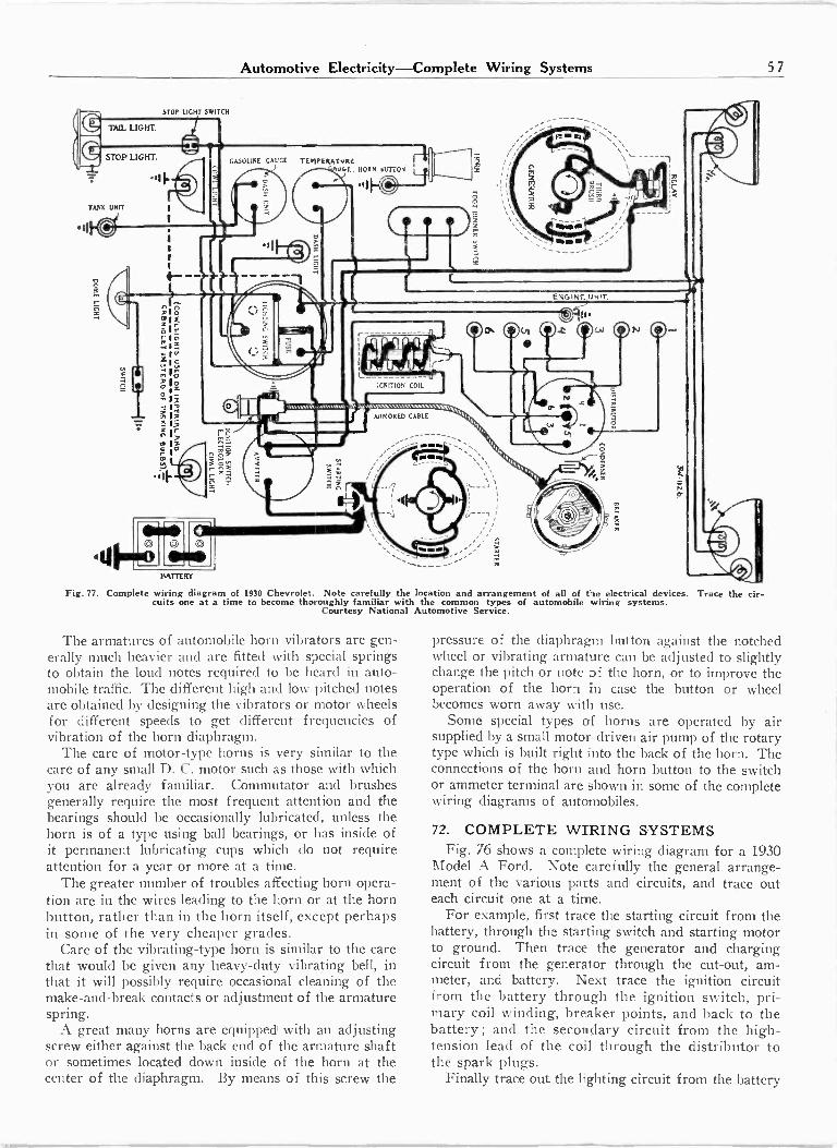
Automotive Electricity-Complete Wiring Systems 57
I
STOP LIGHT SWITCH
TAIL LIGHT.
STOP LIGHT.
TANK UNIT
1111111110.11
BATTERY
GASOLINE GAUGE T E vl PEILATuRCoLE. HORN alls
IGNITION COIL
AMW..6. A 1A. NANSWILWAN,
1
-I
ARMORED CABLE
Fig. 77. Complete wiring diagram of 1930 Chevrolet. Note carefully the location and arrangement of all of the electrical devices. Trace the cir-cuits one at a time to become thoroughly familiar with the common types of automobile wiring systems.
Courtesy National Automotive Service.
The armatures of automobile horn vibrators are gen-erally much heavier and are fitted with special springsto obtain the loud notes required to be heard in auto-mobile traffic. The different high and low pitched notesare obtained by designing the vibrators or motor wheelsfor different speeds to get different frequencies ofvibration of the horn diaphragm.
The care of motor -type horns is very similar to thecare of any small D. C. motor such as those with whichyou are already familiar. Commutator and brushesgenerally require the most frequent attention and thebearings should be occasionally lubricated, unless thehorn is of a type using ball bearings, or has inside ofit permanent lubricating cups which do not requireattention for a year or more at a time.
The greater number of troubles affecting horn opera-tion are in the wires leading to the horn or at the hornbutton, rather than in the horn itself, except perhapsin some of the very cheaper grades.
Care of the vibrating -type horn is similar to the carethat would be given any heavy-duty vibrating bell, inthat it will possibly require occasional cleaning of themake -and -break contacts or adjustment of the armaturespring.
A great many horns are equipped with an adjustingscrew either against the back end of the armature shaftor sometimes located down inside of the horn at thecenter of the diaphragm. By means of this screw the
pressure of the diaphragm button against the notchedwheel or vibrating armature can be adjusted to slightlychange the pitch or note of the horn, or to improve theoperation of the horn in case the button or wheelbecomes worn away with use.
Some special types of horns are operated by airsupplied by a small motor -driven air pump of the rotarytype which is built right into the back of the horn. Theconnections of the horn and horn button to the switchor ammeter terminal are shown in some of the completewiring diagrams of automobiles.
72. COMPLETE WIRING SYSTEMSFig. 76 shows a complete wiring diagram for a 1930
Model A Ford. Note carefully the general arrange-ment of the various parts and circuits, and trace outeach circuit one at a time.
For example, first trace the starting circuit from thebattery, through the starting switch and starting motorto ground. Then trace the generator and chargingcircuit from the generator through the cut-out, am-meter, and battery. Next trace the ignition circuitfrom the battery through the ignition switch, pri-mary coil winding, breaker points, and back to thebattery; and the secondary circuit from the high-tension lead of the coil through the distributor tothe spark plugs.
Finally trace out the lighting circuit from the battery
(0
4t1
.11
510To*EX;rr4 I F,
ytV
w. OttO 1I
;Itf- I
sr-
i 2
o
\ 114.
Fl.11
OO
;
1/./.6.
-------0
;:
E4C04F-
it

58 Automotive Electricity-Wiring Systems
TAIL LIGHT.
STOP LIGHT.
BATTERY
STOP LIGHT SWITCH
p.
IGNITION SWITCH
.111-CyHORN BUTTON
Fig. 78. Wiring diagram of 1930 Oldsmobile car. Note the circuit breaker or current limit relay used for short circuit andalso the thermostat overload device for protection to the generator.
Courtesy National Automotive Service.
through the ammeter, lighting switch, and to the variouslights.
Note that the wires of different parts of the systemhave insulation with different colored markings, whichis a great aid in tracing circuits on the car and shootingtrouble in various parts of the system.
Fig. 77 shows the complete wiring diagram and allof the electrical devices for the 1930 model Chevrolet.
The electrical equipment used on these cars is madeby the Delco Remy Company, who are one of the largermanufacturers of automotive electrical equipment.
Trace out this circuit very carefully and you willnote that although there are some small differences inthe arrangement of parts and wires, the general systemand principle are very much the same as in Fig. 76.
Fig. 78 shows the complete wiring diagram of a 1930Oldsmobile, which is also equipped with Delco Remyapparatus.
Fig. 79 shows the wiring system of an eight -cylinderPackard automobile, using two coils and the doublebreaker contacts.
In addition to the automotive electrical equipmentmade by the Delco Remy Company of Dayton, Ohio,there is also that supplied by two other leading manu-facturers-The Northeast Electric Company, Roches-ter, N. Y., and the Autolite Corporation of Toledo,Ohio. These concerns make most of the electric devices
overload protection, and
for automobiles; while magneto ignition systems fortrucks, tractors, marine engines, etc., are supplied bythe American Bosch Corporation at Springfield, Mass.;Eisemann Magneto Corporation, New York, N. Y.;Sims Magneto Company, Orange, N. J., and severalothers.
It is a very good plan to keep in mind that specialinformation on various ignition devices or repair partscan always be obtained by writing directly to the manu-facturers or by getting in touch with their nearest localdistributor.
For those who may wish to specialize in automotiveelectrical service there are special service manuals orbooks containing wiring diagrams of practically allcars and trucks manufactured.
These diagrams are very convenient to have on handwhen tracing troubles or testing circuits of certainmakes of cars, but as these systems are a great dealalike in many respects and are far too numerous toinclude all of them here, we have just shown a few ofthe most common types to give you a general idea ofcomplete automobile wiring systems.
The wiring diagram for any certain make of car cangenerally be obtained without charge from the automo-bile manufacturers, or we will be glad to supply at anytime information as to where you can obtain specialbooks on wiring diagrams for any graduates who maymake a specialty of automotive electrical work.
rti4t2"1

Automotive Electricity-Wiring Systems 59
STOP LJGHT
NL.UGHT.
BACKING LIGHT SWITCH
STOP LIGHT SWITCH
BATTERY
IGNITION COIL
H.RD.s-RicL1511
's
l 181 '( -
. d a Ili 1
., , Li-,
Fig. 79. Complete wiring diagram of an eight -cylinder Packard automobile. Note the two ignition coils and high speed distributor with doublebreaker arms used on this "line eight' engine. Also note the peculiar field coil construction in the starting motor by which one large coil wirearound the motor frame is used to produce alternate poles in the field pole cores. Courtesy National Automotive Service.
Whether or not you make automotive electricity yourregular trade or business, remember that to be able tolocate and repair electrical troubles on your own carwill often come very handy and will save you consid-erable time and money ; and it may also enable you tomake extra money on the side by repairing the ignitionequipment of someone else's car.
Keep in mind at all times that systematic, thoughtful
circuit tracing and testing will locate any electricaltrouble that can possibly occur in any part of an auto-mobile ignition or wiring system; and that in a greatmajority of cases these troubles arise from such simplethings as loose connections, shorts or grounds, all ofwhich can be easily repaired by anyone with the generalknowledge of electricity that you should have from yourcourse and this reference set.
-77:
I
r
.1P I
STARTING SWITCH
r1 nI 1
_
1-z
O


![w w w .stjo se p h w estp h alia.o rg u ] oW ] Z } 8 i} Z ... · (573) -455 -2320 125 E ast M ain Street w w w .stjo se p h w estp h alia.o rg u ] oW ] Z } 8 i} Z Á Z o ]X } P](https://img.pdfslide.us/doc/110x75/5f3d0330caf6be79e152c58c/w-w-w-stjo-se-p-h-w-estp-h-aliao-rg-u-ow-z-8-i-z-573-455-2320-125.jpg)