Embed Size (px)
Citation preview

ELECTRICAL POWER
FUEL CELL CONTROL CIRCU:TS
P-140
OXYGEN TANKS (2)
HYDROGEN TANKS (2)
+Y "4
.z
t ... . y.
J +Z
Location of major electrical power subsystem equipment
The electrical power subsystem provides electrical energy sou rces, power generation and control, power conversion and conditioning, a nd power distribution to the spacecraft throughout the mission. For checkout before launch, de electrical power is suppl ied by ground support equipment. The electrical power subsystem furnishes drinking water to the astronauts as a byproduct of its fuel cel l powerplants, and includes the cryogenic gas storage system.
Each of the three fuel cel l powerplants (produced by U nited Aircraft Corp.'s Pratt & Whitney Aircraft Division, Hartford, Conn.) consists of 31 cells connected in series. Each cell consists of a hydrogen compartment, an oxygen compartment, and two electrodes (conductors) - one hydrogen and one oxygen. The electrolyte (substance through which ions are conducted) is a mixture of approximately 72 percent potassium hydroxide and approximately 28 percent water and provides a constant conduction path between electrodes. The hydrogen electrode is nickel and the oxygen electrode is nickel and nickel oxide.
The reactants ( hydrogen and oxygen) are supplied to the cel l u nder regu lated pressure (referenced to
a nitrogen gas supply which also is used to pressurize the powerplants). Chemical reaction produces electricity, water, and heat, with the reactants being consumed in proportion to the electrical load. The byproducts-water and heat-are used to maintain the drinking water supply and to keep the electrolyte at the proper operating tem perature. Excess heat is rejected to space through the space rad iators. The fuel cel l powerplants are l ocated in Sector 4 of the service module.
Three silver oxide-zinc storage batteries supply power to the CM during entry and after landing, provide power for sequence controllers, and supplement the fuel cel ls during periods of peak power demand. These batteries are located in the lower equipment bay of the CM. A battery charger located in the same bay re-charges the batteries after each use and assures that they wi l l be ful ly charged before entry. These batteries are produced by Eagle Picher Co., Jopli n, Mo.
Two other silver oxide-zinc batteries, independent of and completely isolated from the rest of the de power system, are used to supply power for explosive devices. These batteries are not recharged. They are produced by the E lectric Storage Battery Co., Raleigh, N .C.
99

The cryogenic (u ltra low temperature) gas storage system (produced by Beech Aircraft Corp., Boulder, Co lo . ) suppl ies the hydrogen and oxygen used in the fuel cel l powerp lants, as well as the oxygen used in the environmental control su bsystem. The system consists of storage tanks and associated valves, switches, l ines, and other plumbing. The hydrogen and oxygen are stored in a semi-gas, semi-l iquid state; by the time they reach the fuel cells, however, they have warmed considerably and are in a gaseous state. The system is located in Sector 4 of the service modu le beneath the fuel cel l powerplants.
Three sol id-state inverters, located in the lower equ ipment bay of the CM, supply the ac power for the spacecraft. These inverters are devices which convert de electrical power into ac. Both the fuel cel l powerp lants and batteries, the two electrical power sources in the spacecraft, produce de power.
The inverters operate from the two 28-volt de m ain buses (connecting circuits) to supply 1 15/1 20-volt, 400-cycle, 3-phase ac power to two ac buses. N ormal ly two inverters are used; however, one inverter can supply a l l primary ac electrical power needed by the spacecraft. If one inverter fails, a crewman can switch in the standby. Two inverters cannot be para l leled (hooked u p together) .
The inverters are produced by Westinghouse E lectric's Aerospace Electrical Division, Lima, Ohio.
EQUIPMENT Oxygen Tanks (Beech Ai rcraft Corp., Boulder,
Colo.) - Two spherical dewar-type tanks made of I nconel (n ickel-steel a l loy) in Sector 4 of the service module store oxygen for production of power by fuel cel ls, for command module pressurization, and for metabolic consumption. Outer diameter of each is 26.55 inches and wal l thickness is 0.020 inch. Tanks with accessories are 36.39 inches tall. Each tank has an inner vessel with a diameter of 25.06 inches and wal l thickness of 0.061 inch. Rupture pressure of the tanks is 1 530 pounds per square inch. I nsulation between the inner and outer shells is fiberglass, paper mating, and aluminum foil. I n addition, a pump maintains a vacuum between the inner and outer vessels. Each tank weighs 79- 1 /2 pou nds, has a volume of 4. 73 cubic feet, and a capacity of 320 pounds - 210 pounds for fuel cel ls and 1 1 0
100
EFFICIENCY WEIGHT 245 LB.
RATING 1.42 KW 29! 2 v
1 KW HOUR ELECTRICITY PER 0.77 LB. OF REACTANT
SHOCK MOUNT (3) �--.....:"'-••
MODULE SUPPORT ASSEMBLY--;::;�-=;�---..-)
'-. ....... ____ ..,.,,
; I
I I
,
1------- 22 IN. -----;
P-141 Fuel cell powerplant
441N.
pounds for environmental control. Each tank has a repressurization probe with two heaters and two fans to keep the tank pressurized and a capacitive probe which measures the amount of oxygen. A resistance element measures temperature.
Hydrogen Tanks ( Beech) - Two spherical dewartype titan ium tanks located in Sector 4 of the service module contain the hydrogen that powers the fuel cel l . Outer diameter of each is 3 1 .80 inches and wal l thickness is 0.033 inch. Each tank is 3 1 .9 inches ta l l and has an inner vessel 28.24 inches in diameter with a wa l l thickness of 0.046 inch. R u pture pressure is 450 pounds per square inch . Unl i ke the oxygen tank, which has insulation between the inner and outer shells, the hydrogen tanks have a vapor-cooled shield suspended in a vacuum as a heat barrier. Each tank weighs 69

pounds, has a volume of 6.75 cubic feet, and a capacity of 28 pounds of usable fluid. Simi lar to the oxygen tanks, they contain repressurization and capacitive probes, a pump to ma intain the vacuum, and temperature transducers.
Batteries ( E agle Picher Co., Jopl in , Mo.) - Three silver oxide-zinc storage batteries are in the command module lower equipment bay. E ach has 20 cells with potassium hydroxide and water as an electrolyte. Battery cases are plastic, coated with fiberglass epoxy, and are vented overboard for outgassing. Each is 6-7/8 by 5-3/4 inches and weighs 28 pounds. The batteries are rated at 40 ampere hours, providing a high power-to-weight ratio. Open circuit voltage is 37.2 volts. The battery characteristics are such that a minimum of 27 volts can be maintained until the battery is depleted. The batteries have been shock-tested to 80-g impact. The batteries provide a l l CM power during entry and after landing. They a lso supplement fuel cel ls during major thrusting maneuvers and provide power for the sequence system and fuel cell and inverter control circu its.
Battery Charger - The constant-voltage, currentl imited charger is 4 by 6 by 6 inches and weighs 4.3 pounds. The current is l imited to 2.8 amperes so as not to overheat the batteries. I t has an
INVERTER NO.3
INVERTER OC
CONTROL BOX
INVERTER NO.2
operating l ife of more than 1 ,000 hours. The charger is located near the entry and postlanding batteries.
Pyrotechnic Batteries ( E lectric Storage Battery Co., Ra leigh, N.C. ) - Each of the two silver oxide-z inc batteries in the lower equipment bay has 20 cells with potassiu m hydroxide and water as an electrolyte. The cases are plastic. There is a relief valve venting arrangement for outgassing. Each is 2-3/4 by 3 by 6-3/4 inches and is rated at 0.75 ampere hours with an open-circuit voltage of 37.2 volts and a 20-volt minimum u nderrated load. They power m i ld explosive devices for CM-SM separation, parachute deployment and separation, Saturn third stage separation, launch escape tower separation, and other functions.
Fu e l C e l l Powe rp l a nts ( U n i t e d Aircraft Corporation's Pratt & Whitney Aircraft D ivision, Hartford, Conn.) - Three fuel cell powerplants, each 44 inches high, 22 inches in diameter, and weighing 245 pounds, are located in Sector 4 of the SM. They are mainly constructed of titanium, stainless steel , and nickel. They are rated at 27 to 3 1 volts under normal loads. There are 3 1 separate ce l ls in a stack, each producing 1 volt, with potassium hydroxide and water as electrolyte. Each cel l consists of a hydrogen and an oxygen
PYRO BATTERY B PYRO BATTERY A
7
�TO BATTERY VENT VALVE
ON WASTE MANAGEMENT PANEL
BATTERY C UNOER POLYMIDE COVER
P-142 Electrical power subsystem components in CM lower equipment bay
101

electrode, a hydrogen and an oxygen gas compartment, and the electrolyte. Each gas reacts independently to produce a flow of electrons. The fuel cells are nonregenerative. They are normally operated at 400 degrees F with l imits of 385 and 500 degrees. Water-glycol is used for temperature control . The fuel cells use hydrogen, oxygen, and nitrogen under regulated pressure to produce power and, as a by-product, water.
I nverters (Westinghouse Electric's Aerospace E I ectrical Division, Lima, Ohio) Three solid-state inverters are in the lower equ ipment bay. Each is contained in an a luminum enclosure and coldplated with a water-glycol loop. The inverters weigh 53 pounds each and are 1 4-3/4 by 1 5 by 5 inches. They produce 1 250 volt-amperes each. They convert 28-volt de to 1 1 5-volt ac, 3
phase, 400 Hertz. They are designed to compensate for input and output voltage variations. Two of the three inverters are in constant use. They provide alternating current for fuel cel l pumps, environmental control system glycol pumps, space suit compressors, and other circuitry.
DETAILED DESCRIPTION CRYOGEN I C STORAGE
The cryogenic storage subsystem supplies oxygen and hydrogen to the fuel cel l powerplants and oxygen to the environmental control subsystem and for in itial pressu rization of the lunar module. Each of the two tanks of hydrogen and oxygen holds enough f lu id to assure a safe return from the furthest point of the mission. The cryogenic tanks
Command module wire harness is first assembled on this mockup stand
102

DENSITY SENSOR
INSULATION
ELECTRICAL CONNECTOR
HEATER & DESTRATIFICATION UNIT
OUTER SHELL
FEED L I N E
P-144 Cryogenic tank (hydrogen)
are pressurized by internal heaters after f i l l ing is complete .
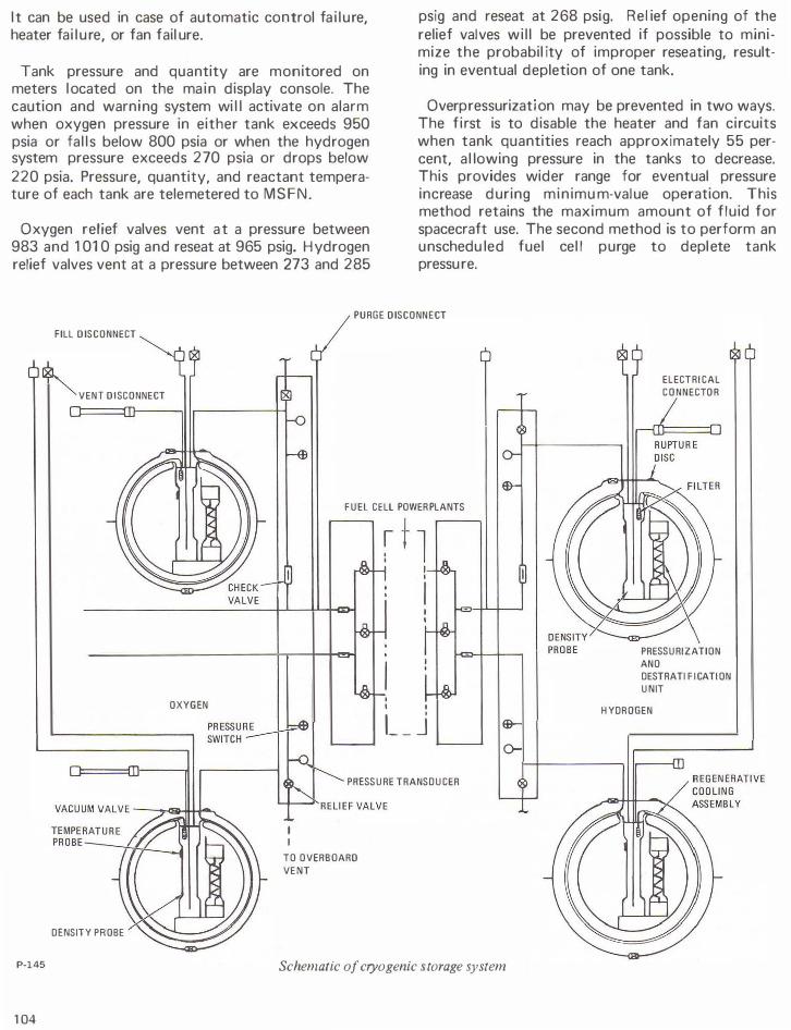
Two pa rallel de heaters in each tank supply heat necessary to maintain pressure. Two paral lel 3-phase ac circulating fans circulate the f l uid over the heating elements to ma intain a uniform density and decrease the probability of thermal stratification. Relief va lves provide overpressure relief and check valves provide tank isolation. A malfunctioning fuel cell powerplant can be isolated by a shutoff valve. F i l ters extract particles from the flowing fluid to protect components. Pressure transd ucers and temperature probes indicate the thermodynamic state of the f luid and capacitive quantity probes indicate the amount of fluid in the tanks.
The systems can be repressurized automatically or manual ly. The automatic mode is designed to give a single-phase reactant flow into the fuel cel l and feed l i nes at design pressures. The heaters and fans are automatically controlled through pressure and motor switches. As pressure decreases, the pressure switch in each tank closes to energize the motor switch, closing contacts in the heater and fan circuits. Both tanks have to decrease in pressure before heater and fan circuits are energized. When either tank reaches the upper operating pressure l i mit, its pressure switch opens, again energizing the motor switch and opening the heater and fan circuits to both tanks. The oxygen tank circuits are
energized at 865 psia mi nimum and de-energized at 935 psia maximum. The hydrogen circuits energize at 225 psia mini mum and de-energize at 260 psia maximum.
When the systems reach the point where heater and fan cycling is at a minimum (due to a reduced heat requirement), the heat leak of the tank is sufficient to maintain proper pressures provided flow is with in proper val ues. The minimum heat requirement region for oxygen starts at approximately 40-percent quantity in the tanks and ends at approximately 25-percent quantity. Between these tank quantities, minimum heater and fan cycl ing wi l l occur under normal usage. The heat needed for pressurization at quantities below 25 percent starts to increase until at the 5-percent level practically continuous heater and fan operation is required. I n the hydrogen system, the quantity levels for minimum heater and fan cycling are between approximate ly 53 and 33 percent, with continuous operation occurring at approximately 1 percent.
The oxygen system heaters and fans can sustain proper pressures for 30 minutes at a total flow of 1 0.4 pounds per hour (5.2 pounds per hour per tank) . The hydrogen system heaters and fans can sustain proper pressures at a total flow of 1 .02 pounds per hour (0.51 pound per hour per tank).
Manual repressurization supplies power directly to the heaters and fans through the control switches.
103
I t can be used in case of automatic control fa i lure, heater fai lure, or fan fail ure.
Tank pressure and quantity are monitored on meters located on the main display console. The caution and warning system wi l l activate on alarm when oxygen pressure in either tank exceeds 950 psia or fal l s below 800 psia or when the hydrogen system pressure exceeds 270 psia or drops below 220 psia. Pressure, quantity, and reactant temperature of each tank are telemetered to MSFN.
Oxygen relief valves vent at a pressure between 983 and 1 01 0 psig and reseat at 965 psig. Hydrogen relief valves vent at a pressure between 273 and 285
psig and reseat at 268 psi g. Rel ief opening of the relief valves wi l l be prevented if possible to minimize the probabil ity of improper reseating, resulting in eventual depletion of one tank.
Overpressurization may be prevented in two ways. The first is to disable the heater and fan circuits when tank quantities reach approximately 55 percent, a l lowing pressure in the tanks to decrease. This provides wider range for eventual pressure increase during min imu m-value operation. This method retains the maximum amount of f lu id for spacecraft use. The second method is to perform an unschedu led fuel cel l purge to deplete tank pressure.
PURGE DISCONNECT
FILL DISCONNECT
VENT DISCONNECT
OXYGEN
DENSITY PROBE
P-145
104
FUEL CELL POWER PLANTS
I I I
l__j
PRESSURE TRANSDUCER
I I
TO OVERBOARD VENT
Schematic of cryogenic storage system
ELECTRICAL CONNECTOR
PRESSURIZATION ANO DESTRATI F ICATION UNIT
HYDROGEN

P-146 -------
Cryogenic tank pressure and quantity measurement devices
The reactant tanks have vacuum-ion pumps which function as ion traps to maintain the vacuum between the inner and outer shells.
BATTE R I ES
The five silver oxide-zinc storage batteries of the electrical power subsystem are located in the lower equipment bay of the CM.
Three rechargeable entry and post- landing batteries (A, B, and C) power the CM systems after CM-SM separation. Before separation, the batteries provide a secondary source of power wh ile the fuel cells are the primary source. They supplement fuel cel l power during peak load periods (velocity change maneuvers), provide power during emergency operations (failure of two fuel cel ls) , and provide power for power subsystem control c ircuitry ( relays, indicators, etc.) and sequencer logic. They can also be used to power pyro circuits.
Each entry and post-landing battery consists of 20 silver oxide-zinc cells connected in series. The cells are individual ly encased in plastic containers which contain relief valves that open at 35 ± 5 psig, venting during an overpressure into the battery case. Each battery case is vented overboard through
a common manifold and the urine/water dump l i ne. The vent I ine prevents battery-generated gas from entering the crew compartment.
I n the event a battery case fractures, the vent is closed. The battery manifold pressure is monitored on the meter and when it approaches CM pressure the vent valve is opened to prevent the gas going into the cabin. Battery manifold pressure can be used as an indication of urine/waste water dump line plugging.
Each battery delivers a mm1mum of 40 amperehours at a current output of 35 amps for 1 5 minutes and a subsequent output of 2 amps, or at a current output of 25 amps for 30 mi nutes and a subsequent output of 2 amps. At Apo l lo mission
loads, each battery can provide 50 ampere-hours.
Open circuit voltage is 37.2 volts. Since susta ined battery loads are extremely light (2 to 3 watts) , voltages very close to open circuit voltage wil l be indicated on the spacecraft voltmeter, except when the main bus tie switches have been activated to tie the battery output to the main de buses. Normal ly only batteries A and B wi l l be connected to the main de buses. Battery C is isolated during the pre-launch period and provides a backup for main de bus power. The two-battery configuration provides more efficient use of fuel cel l power during peak power loads and decreases overa l l battery recharge time.
The two pyrotechnic batteries supply power to activate ordnance devices in the spacecraft. The
P-147 Pyrotechnic battery
105

pyrotechnic batteries are isolated from the rest of the electrical power system to prevent the h igh power su rges in the pyrotechnic system from affecting it and to assure source power when requ ired. These batteries are not recharged in f l ight. The entry and post-landing batteries can be used as a redundant source of power for initiating pyro circuits if either pyro battery fails.
FUEL C ELL POWERPLANTS
Each of the three Bacon-type fuel cel l powerplants is individually coupled to a heat rejection (radiator) system, the hydrogen and oxygen cryogenic storage systems, a water storage system, and a power distribution system.
The powerplants generate de power on demand through an exothermic chemical reaction. A byproduct of this chemical reaction is water, which is fed to a potable water storage tank in the CM where it is u sed for astronaut consumption and for cooling purposes in the environmental control subsystem. The amount of water produced is proportional to
the ampere-hours.
Each powerplant consists of 3 1 single cells connected in series and enclosed in a metal pressu re jacket. The water separation, reactant control, and heat transfer components are mou n ted in a compact accessory section attached directly above the pressure jacket.
Powerplant temperature is controlled by the primary (hydrogen) and secondary (glycol) loops. The hydrogen pump, providing continuous circulation of hydrogen in the primary loop, withdraws water vapor and heat from the stack of cells. The primary bypass valve regu lates flow through the hydrogen
I
P-148
Location of electrical power subsystem radiators
106
BAY 1
BAY 2
SECONDA R Y BYPASS VALVE
HYDROGEN. OXYGEN PRESSURE REGULATORS CONDENSER
WATER SEPARATOR PUMP WATER PURITY SENSOR HYO ROGEN. OXYGEN PRESS U R E TRANSDUCERS 2-STEP NITROGEN GAS REGULATOR
HYDROGEN,OXYGEN PREHEATERS GLYCOL REGEN
HYDROGEN, OXYGEN PURGE VALVES IN LINE HEATER CONTROL
NITROGEN STORAGE TANK
NITROGEN PRESSURE TRANSDUCER
P-149
WATER OUT OXYGEN VENT
OXYGEN SUPPLY
HYD ROGEN SUPPLY
HEATERS CONTROLS
NSTRUMENTATION
Fuel cell module accessories
regenerator to i mpart exhaust heat to the incoming hydrogen gas as req u i red to maintain the proper cel l temperature. The exhaust gas flows to the condenser where waste heat is transferred to the glycol, the resu ltant temperature decrease l iqu ifying some of the water vapor. The motor-driven centrifugal water separator extracts the l iquid and feeds it to the potable water tank i n the CM. The temperature of the hydrogen-water vapor exiting from the condenser is controlled by a bypass valve which regu lates flow through a secondary regenerator to a control condenser exhaust within desired l i mits. The cool gas is then pu mped back to the fuel cel l through the primary regenerator by a motor-driven

vane pump, which also compensates for pressure losses due to water extraction and cooling. Waste heat, transferred to the glycol in the condenser, is transported to the radiators located on the fairing between the CM and SM, where it is radiated into space. Radiator area is sized to reject the waste heat resu lting from operation i n the normal power range. I f an emergency arises in which an extremely low power level is requ ired, individual controls can bypass three of the eight radiator panels for each powerplant. This area reduction improves the margin for radiator freezing which cou ld resu lt from the lack of sufficient waste heat to maintain adequate glycol temperature. This is not a normal procedure and is considered irreversible due to freezing of the bypassed panels.
Reactant valves provide the connection between the powerp lants and the cryogenic system. They are opened during pre-launch fuel cell startup and closed only after a powerplant malfunction necessitating its isolation from the cryogenic system. Before launch, a valve switch is operated to apply a holding voltage to the open solenoid of the hydrogen and oxygen reactant valves of the three powerplants. This voltage is required only during
1
P-150
boost to prevent inadvertent closure due to the effects of high vibration. The reactant valves cannot be closed with this holding voltage appl ied. After earth orbit insertion, the holding voltage is removed and three circuit breakers are opened to prevent valve closure through inadvertent activation of the reactant valve switches.
Nitrogen is stored in each powerplant at 1 500 psia and regu lated to a pressure of 53 psia. Output of the regu lator pressurizes the electrolyte in each cell through a diaphragm arrangement, the coolant loop through an accumulator, and is coupled to the oxygen and hydrogen regulators as a reference pressure.
Cryogenic oxygen, supplied to the powerplants at 900±35 psia, absorbs heat in the l i nes, absorbs additional heat in the fuel cell powerp lant reactant preheater, and reaches the oxygen regulator in a gaseous form at temperatures above 0° F. The differential oxygen regulator reduces pressure to 9.5 psia a bove the nitrogen reference, thus supplying it to the fuel cel l stack at 62.5 psia. Within the porous oxygen electrodes, the oxygen reacts with the water in the electrolyte and the electrons
Flow and control of electrical power subsystem radiators
107

provided by the external c1rcu it to produce hydroxyl ions.
Cryogenic hydrogen, supplied to the powerplants at 245 (+1 5, -20) psia, is heated in the same manner as the oxygen. The differential hydrogen regu lator reduces the pressure to 8.5 psia above the reference nitrogen, thus supplying it in a gaseous form to the fuel cells at 6 1 .5 psia. The hydrogen reacts in the porous hydrogen electrodes with the hydroxyl ions in the electrolyte to produce electrons, water vapor, and heat. The nickel electrodes act as a catalyst in the reaction. The water vapor and heat are withdrawn by the circulation of hydrogen gas in the primary loop and the electrons are supplied to the load.
Each of the 31 cells compnsmg a powerplant contains electrolyte which on initial f i l l consists of approximately 83 percent potassium hydroxide (KOH) and 1 7 percent water by weight. The powerplant is initial ly conditioned to increase the water ratio, and during normal operation, water content wi l l vary between 23 and 28 percent. At this ratio, the electrolyte has a critical temperature of 360° F . Powerplant electrochemical reaction becomes effective at the critical temperature. The powerplants are heated above the critical temperature by ground support equ ipment. A load on the powerplant of approximately 563 watts is required to maintain it above the normal minimum operating temperature of 385° F. The automatic in-l ine heater circuit wi l l maintain powerplant temperature in this range with smaller loads applied.
Purging is a function of power demand and gas purity. Oxygen purging requires 2 m inutes and hydrogen purging 80 seconds. The purge frequency is determined by the mission power profile and gas purity as sampled after spacecraft tank f i l l . A degradation purge can be performed if powerplant current output decreases approximately 3 to 5
REACTANT IN
P-151
108
Construction of cell
REACTANT OUT
NICKEL ELECTRODE�
HYDROGEN
POTASSIUM A HYDROXIDE
NITROGEN
P-152
OXYGEN
V NICKEL + NICKEL OXIDE ELECTRODE
WELDS
NITROGEN
SPACER
Cutaway view of cell
amps during sustained operation. The oxygen purge has more effect during this type of purge, although it wou ld be followed by a hydrogen purge if recovery to normal were not realized. If the performance degradation were due to powerplant electrolyte flooding, which would be indicated by activation of the pH high indicator, purging woul d not be performed due to the possibi l ity of increasing the flooding.
The appl ication and removal of fuel cel l loads causes the terminal voltage to decrease and increase, respectively. A decrease in terminal voltage, resulting from an increased load, is fol lowed by a gradual increase in fuel cell skin temperature which causes an increase in terminal voltage. Conversely, an increase i n terminal voltage, resu lting from a decreased load, is fol lowed by a gradual decrease in fuel cell skin temperature which causes a decrease in terminal voltage. This performance change with

temperature is regu lated by the primary regenerator bypass valve and provides the capabi lity of operating over an increased power range within voltage regu lation l imits.
The range i n which the terminal voltage is permitted to vary is determined by the high and low voltage input design l imits of the components being powered. For most components the l i m its are 30 volts de and 25 volts de. To remain within these design l imits, the de bus voltage must be maintained between 3 1 .0 and 26.2 volts de. Bus voltage is maintained within prescribed l imits during high power requirements by the use of entry and post-landing batteries.
Spacecraft systems are powered u p in one continuous sequence providing the main bus voltage does not decrease below 26.2 volts. If bus voltage
POTABLE WATER t;:=:::::t
P-153
COOLANT REGENERATOR
I
GLYCOL TO RADIATOR REACTANT SOV
GLYCOL
GLYCOL
HYDROGEN GAS
P-154
Electrochemical flow in fuel cell
INLINE HEATER CIRCUIT - LOAD+
•-vv-.· I I I I ·311N SERIES)
/j/j;ljjjh�i!<!��:'2::l�� NITR 0 G EN
HYDROGEN FLOW SENSOR
SAMPLING (FOR TEST ONLY)
I I I
FUEL CELL MODULE
NITROGEN �����������R� E�G ULATOR
T NITROGEN VENT
ROGEN SUPPLY LENOIO VALVE
NITROGEN
REACTANT SOV OXYGEN FLOW SENSOR
Schematic of fuel cell module
109
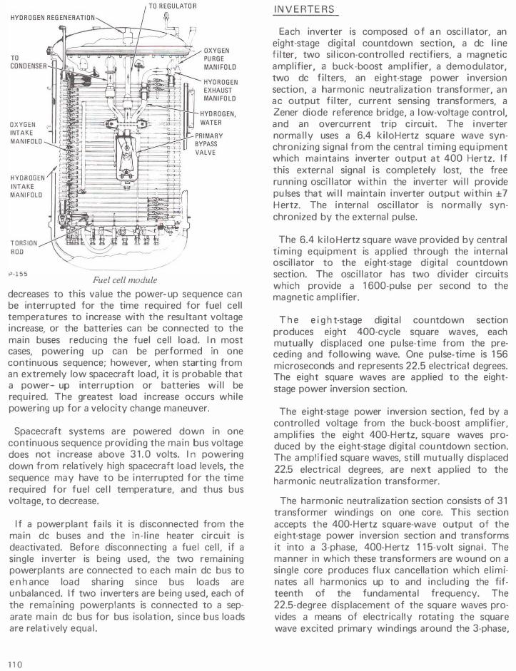
OXYGEN INTAKE MANIFOLD
HYDROGEN INTAKE MANIFOLD
TORSION ROO
1'-155 Fuel cell module
decreases to this value the power-up sequence can be interrupted for the time required for fuel cell temperatures to increase with the resu ltant voltage increase, or the batteries can be connected to the main buses reducing the fuel cell load. I n most cases, powering up can be performed in one continuous sequence; however, when starting from an extremely low spacecraft load, it is probable that a power-- up interruption or batteries wi l l be required. The greatest load increase occurs while powering up for a velocity change maneuver.
Spacecraft systems are powered down in one continuous sequence providing the main bus voltage does not increase above 3 1 . 0 volts. I n powering down from relatively high spacecraft load levels, the sequence may have to be interrupted for the time required for fuel cel l temperature, and thus bus voltage, to decrease.
I f a powerplant fails it is disconnected from the main de buses and the in- l ine heater circuit is deactivated. Before disconnecting a fuel cel l , if a single inverter is being used, the two remaining powerplants are connected to each main de bus to e n h ance load sharing since bus loads are unbalanced. If two inverters are being u sed, each of the remaining powerplants is connected to a separate main de bus for bus isolation, since bus loads are relatively equal.
110
I N V E RTE RS
Each inverter is composed of an osc i l lator, an eight-stage digital countdown section, a de l ine fi lter, two sil icon-controlled rectifiers, a magnetic ampl ifier, a buck-boost ampl ifier, a demodulator, two de filters, an eight-stage power inversion section, a harmonic neutralization transformer, an ac output f i lter, current sensing transformers, a Zener diode reference bridge, a l ow-voltage control, and an overcurrent trip c ircuit. The i nverter normal ly uses a 6.4 ki loHertz square wave synchronizing signal from the central t iming equ ipment which maintains inverter output at 400 Hertz. I f this external signal i s completely lost, the free running osci l lator within the inverter wi l l provide pu lses that wi l l maintain inverter output within ±7 Hertz. The internal osci l lator is normally synchronized by the external pulse.
The 6.4 ki loHertz square wave provided by central timing equipment is applied through the internal oscillator to the eight-stage digital countdown section. The osci l lator has two divider circuits which provide a 1 600-pulse per second to the magnetic ampl ifier.
T h e e i g h t-stage digital cou ntdown section produces eight 400-cycle square waves, each mutually displaced one pu lse-time from the preceding and following wave. One pulse-time is 1 56 microseconds and represents 22.5 electrical degrees. The eight square waves are applied to the eightstage power inversion section.
The eight-stage power inversion section, fed by a controlled voltage from the buck-boost amplifier, amplifies the eight 400-Hertz, square waves produced by the eight-stage digital cou ntdown section. The amplif ied square waves, still mutual ly displaced 22.5 electrical degrees, are next applied to the harmonic neutralization transformer.
The harmonic neutralization section consists of 3 1 transformer windings on one core. This section accepts the 400-Hertz square-wave output of the eight-stage power inversion section and transforms it into a 3-phase, 400-Hertz 1 1 5-volt signal. The manner in which these transformers are wound on a single core produces flux cancellation which el iminates al l harmonics up to and includ ing the fifteenth of the fundamental frequency. The 22.5-degree displacement of the square waves provides a means of electrically rotating the square wave excited primary windings around the 3-phase,

\ \
P-156 Pratt & Whitney technicians assemble fuel cell powerplants at plant in Hartford, Conn.
1 1 1

wye-connected secondary windings, thus producing the 3-phase 400 cycle sine wave output. This 1 1 5-volt signal is then applied to the ac output fi lter.
The ac output f i lter elimi nates the remaining higher harmonics. Since the lower harmonics were eliminated by the harmonic neutralization transformer, the size and weight of this output fi lter is reduced. Circuitry in this filter also produces a rectified signal which is applied to the Zener diode reference bridge for voltage regu lation. The amplitude of this signal is a function of the amplitude of ac output voltage. After f i ltering, the 3-phase, 1 1 5-volt ac 400-hertz sine wave is applied to the ac buses through individual phase current-sensing transformers.
The current-sensing transformers produce a rectified signal, the ampl itude of which is a direct function of inverter output current magnitude. This de signal is applied to the Zener diode reference bridge to regulate inverter current output; it is also paral leled to an overcurrent trip circuit.
The Zener diode reference bridge receives a rectified de signal, representing voltage output, from the circuitry in the ac output fi lter. A variance in voltage output unbalances the bridge, providing an error signal of proper polarity and magnitude to the buck-boost amplifier via the magnetic amplifier. The buck-boost amplifier, through its bias voltage output, compensates for voltage variations. When inverter current output reaches 200 to 250 percent of rated current, the rectified signal applied to the bridge from the current sensing transformers is of suff icient magnitude to provide an error signal, causing the buck-boost amplifier to operate in the same manner as during an overvoltage condition. The bias output of the buck-boost ampl ifier, control led by the error signal, wi l l be varied to correct for any variation in inverter voltage or a beyond-tolerance increase in current output. When inverter cu rrent output reaches 250 percent of rated current, the overcurrent trip circuit is activated.
The overcurrent trip circuit monitors a rectified de signal representing current output. When total inverter current output exceeds 250 percent of rated current, this circuit wi l l disconnect an inverter in 1 5± 5 seconds. I f current output of any single phase exceeds 300 percent of rated current, this circuit will disconnect an i nverter in 5 ± 1 seconds.
1 12
-14.51N.---; Size of static inverter
P-157
The disconnect is provided through relays located in the motor switch circuits that connect the inverters to the ac buses.
De power to the inverter is suppl ied from the main de buses through the de l i ne fi lter. The filter reduces the h igh-frequency ripple in the input, and the 25 to 30 volts de is applied to the si l iconcontrolled rect ifiers.
The si l icon-control led rectifiers are alternately set by the 1 600 pulses-per-second signal from the magnetic amplifier to produce a de squ are wave with an on-time of greater than 90 degrees from each rectifier. This is filtered and supplied to the buck-boost amplifier where it is transformercoupled with the amplified 1 600 pulses-per-second output of the magnetic amplifier to develop a fi ltered 35 volts de which is used for amplification in the power inversion stages.
The buck-boost amplifier also provides a variable bias voltage to the eight-stage power inversion section. The ampl itude of this bias voltage is control led by the amplitude and polarity of the feedback signal from the Zener diode reference bridge which is referenced to output voltage and current. This bias signal is varied by the error signal to regu late inverter voltage and maintain current output within tolerance.
The demodulator c ircuit compensates for any low-frequency ripple in the de input to the i nverter. The high-frequency ripple is attenuated by the input fi lters. The demodulator senses the 35-volt de

output of the buck-boost amplifier and the cu rrent input to the buck-boost amplifier. An input de voltage drop or increase wil l be reflected i n a drop or increase in the 35-volt de output of the buck-boost ampl ifier, as well as a drop or increase in cu rrent input to the buck-boost amplifier. A sensed decrease in the buck-boost amplifier voltage output is compensated for by a demodulator output, coupled through the magnetic amplifier to the sil icon-controlled rectifiers. The demodu I at or output causes the sil icon-controlled rectifiers to conduct for a longer time, thus increasing their fi ltered de output. An increase i n buck-boost amplifier voltage output caused by a n i ncrease in d e input to the inverter i s compensated for by a demodulator output coupled through the magnetic amplifier to the sil icon-controlled rectifiers causing them to conduct for shorter periods, thus producing a lower filtered de output to the buck-boost amplifier. In this man ner, the 35-volt de input to the power inversion section is maintained at a relatively constant level irrespective of the fluctuations in de input voltage.
The low-voltage control circuit samples the input voltage to the inverter and can terminate inverter operation. Since the buck-boost amplifier provides a boost action during a decrease in input voltage to the inverter, in an attempt to maintain a constant 35 volts de to the power inversion section and a regulated 1 1 5-volt i nverter output, the high boost required during a low-voltage input wou ld tend to overheat the solid-state buck-boost amplifier. As a precautionary measure, the low-voltage control wil l terminate inverter operation by disconnecting operating voltage to the magnetic amplifier and the fi rst power i nversion stage when input voltage decreases to between 16 and 1 9 volts de.
A temperature sensor with a range of 32° to 248°F is instal led in each inverter and wi l l i l l u m in ate a l ight in the caution and warning system a t a n inverter overtemperature of 1 90°F . I nverter temperature is telemetered to the ground.
BATTERY CHARGER
A constant-voltage, solid-state battery charger is located in the CM lower equipment bay. I t is provided 25 to 30 volts from both ma in d e buses and 1 1 5 volts 400-cps 3-phase from either of the ac buses. All three phases of ac are used to boost the 25 to 30-volt de input and produce 40 volts de for charging. I n addition, Phase A of the ac is used to supply power for the charger circu itry. The logic
network in the charger, which consists of a twostage differential amplifier ( comparator), Schm itt trigger, current-sensing resistor, and a voltage amplifier, sets up the initial condition for operation. The first stage of the comparator is on, with the second stage off, thus setting the Schm itt trigger first stage to on with the second stage off. Maximum base drive is provided to the current amplifier which turns on the switching transistor. With the switching transistor on, current flows from the transformer rectifier through the switching transistor, current sensing resistor, and switch choke to the battery being charged. Current lags voltage due to switching choke action. As cu rrent flow increases, the voltage drop across the sensing resistor increases, and at a specific level sets the first stage of the comparator off and the second stage on. The voltage amp I ifier is set off to reverse the Schmitt trigger to first stage off and second stage on. This sets the current amplifier off, which in turn sets the switching transistor off. This terminates power from the source, causing the field in the choke to continue col lapsing, discharging into the battery, then through the switching diode and the current sensing resistor to the opposite side of the choke. As the electromagnetic field in the choke decreases, cu rrent through the sensing resistor decreases, reducing the voltage drop across the resistor. At some point, the decrease in voltage drop across the sensing resistor reverses the comparator circuit, setting up the i n itial condition and completing one cycle of operation. The output load cu rrent, due to the choke action, rema ins relatively
Entry and post-landing battery
1 13

constant except for the small variation through the sensing resistor. This variation is requ i red to set and reset the switching transistor and Schmitt trigger through the action of the comparator.
Battery charger output is regu lated by the sensing resistor until battery voltage reaches approximately 36 volts. At this point, the biased voltage control network is unbiased, and in conjunction with the sensing resistor provides a signal for cyc l i ng the battery charger. As battery voltage increases, the internal impedance of the battery increases, decreasing current flow from the charger. At 39
volts m inimum, the battery is considered fu l ly charged and current flow becomes negligible.
POWE R DISTRIBUT I ON
De and ac power distribution is provided by two redundant buses in each system. A single-point
SM JETTISON CONTROLLER
ground on the spacecraft structure is used to el imi nate ground loop effects. Sensing and control circu its are provided for monitoring and protection of each system.
De power is distributed with a two-wire system and a series of i nterconnected buses, switches, circuit breakers, and isolation d iodes. The de negative buses are connected to the single-point ground. The buses consist of the following:
1. Two main de buses (A and B), powered by the three fuel cell powerplants and/or entry and post-landing Batteries A, B, and C.
2. Two battery buses (A and B ) , each powered by its respective entry and post-landing battery. Battery C can power either or both buses if the Batteries A or B fai l .
SM JETTISON CONTROLLER
B
F U E L CELL NO.1 FUEL CELL NO.2 FUEL CELL NO.3
UNDER·
VOLTAGE SENSING
iF Ll G HT BUS t-1----f+--o
BUS A (SM)
CM INTERRUPTER
...----....
AUTOMATIC REACTION CONTROL TRANSFER
P-159
1 14
I BATTERY C
LA�A I
N.O. • NORMALLY OPEN
DC power distribution
OFF
o-- A (TO BAT BUS A)
-- B (TO BAT BUS B)
-c(TO BAT C)
BUS B (SM)
UMBILICAL
UNDER·
VOLTAGE
SENSING
I FLIGHT sus} mf"U CHARGE
'::1:: X
0} rr 9
AUTOMATIC REACTION CONTROL TRANSFER

3. F l ight and post-landing bus, powered through both main de buses and diodes, or d i rectly by the three entry and post- landing batteries through dual diodes.
4. Flight bus, powered through both main de buses and isolation diodes.
5. Nonessential bus, powered through either de Main Bus A or B.
6. Battery relay bus, powered by two entry and post-landing batteries (A and B) through the individual battery buses and isolation diodes.
7. Pyro bu ses, isol ated from the main el ectrical power su bsystem when powered by the pyro batteries. Entry batteries can be connected to the A or B pyro system in case of loss of a pyro battery.
8. SM jettison controllers, powered by the fuel cel l powerplants and completely isolated from
MAIN BUSA
MAIN BUS B
r---, INVERTER I I CONTROL BOX I I
I (;;) I I Y I I t ' .. '
I I I I I :� I
I I I I I
• I
I I I I
A ! I
I I
I I I I I .!. I
AI ..... --o � i 7 I I
I 0t I I L ___ ...J
400"' INVERTER NO.1
400 rv INVERTER NO.2
400 "' INVERTER NO.3
a¢
c¢
B¢
C¢
8¢
C</>
the main electrical power subsystem until activated during CSM separation.
Power from the fuel cell powerplants can be connected to the main de buses through six motor switches (part of overload/reverse current circuits in the SM) which are controlled by switches in the CM. Fuel cel l power can be connected to either or both of the main de buses. When an overload occurs, the overload-reverse current c ircuits i n the SM automatical ly disconnect the fuel cell powerplants from the overloaded bus and provide visual displays for isolation of the trouble. A reverse current condition will disconnect the malfunctioning powerplant from the de system. De u ndervoltage sensing circuits are provided to indicate bus low-voltage conditions. If voltage drops below 26.25 volts de, the applicable de undervoltage l ight on the caution and warning panel wi l l i l luminate. Since each bus is capable of handling all loads, an undervoltage condition should not occur except in an isolated instance ( if too many electrical u nits are
AC BUS 1
AC SENSOR
A¢
SPACECRAFT LOA OS
AC CONTROL BOX AC BUS 2
�----:Q.-....,�� B!_<f> } SLPACECRAFT � OAOS
(6 MOTOR SWITCHES)
co A¢ r'1
Li���fl��===== SPACECRAFT LOADS
B� rn L�
-
II
AC BUS 2 @ @ ACBUS2
1 L OVERLOAD
AC SENSOR
J P-160 AC power distribution
115

placed on the bus simultaneously or if a malfu nction exists i n the subsystem}. A voltmeter is provided to monitor voltage of each main de bus, the battery charger, and each of the five batteries. An ammeter monitors current output of the powerplants, batteries, and battery charger.
During high power demand or emergencies, supplemental power to the main de buses can be supplied from batteries A and B via the battery buses and directly from battery C. Du ring entry, spacecraft power is provided by the three entry and post-landing batteries which are connected to the main de buses before CM -SM separation.
The nonessential bus permits nonessential equipment to be shut off during a shortage of power (two fuel cel l powerplants out}. The flight bus distributes power to in-flight telecommu nications equipment. The flight and post-landing bus distributes power to some of the in-flight telecommunications equipment and float bag No.3 controls. The post- landing bus receives power from the fuel cells or entry and post- landing batteries through the main de buses. After completion of reaction control subsystem ptlrge during main chute descent, the entry batteries supply power to the post-landing bus directly through individual circuit breakers.
The battery relay bus provides de power to the de and ac sensing unit, the fuel ce l l , inverter control circu its, and some of the indicators on the main display console. The pyrotech nic batteries supply power to ordnance devices used during the course ofthe mission. The three fuel cel l powerplants supply
116
power to the SM jettison controllers for the SM separation maneuver.
Ac power is distributed with a four-wire system via two redundant buses, 1 and 2. The ac neutral bus is connected to the single-point ground. Ac power is provided by one or two of the solid-state 1 1 5/200-volt 400-cps 3-phase inverters. De power is routed to the inverters through the main de buses. I nverter N o. 1 is powered through de Main Bus A, inverter No. 2 through de Main Bus B, and inverter No. 3 through either de Main Bus A or B by switch selection. Each of these circuits has a separate circuit breaker and a power control motor switch. The three inverters are identical and are provided with overtemperature circuitry. A l ight indicator in the caution and warning group i l luminates at 1 90°F to indicate overtemperature. I nverter output is routed through a series of control motor switches to the ac buses. Six switches control motor switches which operate contacts to connect or disconnect the inverters from the ac buses. The motor switch circuits are designed to prevent connecting two inverters to the same ac bus at the same time. Ac loads receive power from either ac bus through bus selector switches. I n some instances, a single phase is used for operation of equipment and in others all three. Over- or undervoltage and overload sensing circuits are provided for each bus. Inverters are automatical ly disconnected during overvoltage or overload. Ac bus voltage fail and overload l ights in the caution and warn ing group indicate voltage or overload malfu nctions. Phase A voltage of each bus is telemetered to grou nd stations.

WATE R MANAGEM ENT
The potable and waste water tanks are partial ly fi l led before launch to assure an adequate supply during early stages of the mission. Through the rest of the mission until CM-SM separation, the fuel cell powerplants supply potable water. A portion of the water is chi l led for drinking and food preparation, and the remainder is heated and del ivered through a separate valve in the food preparation u n it. Provision is made to sterilize the potable water.
T H E R M A L CONT R O L
Spacecraft heating and cool ing is performed through two water-glycol coolant loops. The waterglycol, initial ly cooled through ground equ ipment, is pumped through the primary loop to cool operating electric and electronic equipment and the suit and cabin heat exchangers. The water-glycol also is circu lated through a reservoir in the CM to provide a heat sink ( heat-absorbing area) during ascent.
The water-glycol is a heat-absorbing medium; it picks up excess heat from operating equipment and
SENSOR AMPLIFIER
CABIN TEMPERATURE TRANSDUCER
CABIN TEMPERATURE ANTICIPATOR
CABIN TEMPERATURE SENSOR
P-163
Cabin temperature unit
the heat exchangers and is routed to the service module, where it passes through radiator tubes on the outside skin. The glycol mixture radiates its heat to space in its passage through these tubes, which are exposed to the cold of space. Then the mixture, now cold again, returns to the CM and repeats the cycle.
During ascent the radiators are heated by aerodynamic friction so a bypass valve is used to shut off the SM portion of the water-glycol loop. From l iftoff u ntil 1 1 0,000 feet excess heat is absorbed by the coolant and by pre-ch i l l ing of the structure; above 1 1 0,000 feet the excess heat is rejected by evaporat ing water in the primary glycol evaporator.
Temperature i n the cabin is controlled by the way the water-glycol is routed. Normal l y it passes through the space radiators and returns to pick up and dissipate heat, thus cool ing the cabin. If heating is needed, the coolant can be routed so that it returns to the cabin heat exchanger after absorbing heat from the operating equipment; this heat wou ld be absorbed into the cabin gas circulated through the cabin heat exchanger by dual fans.
The secondary water-glycol loop is used when additional cooling is needed and before entry. Dual- loop operation may be used to "cold-soak" the CM interior for the plu nge into the atmosphere.
EQUIPMENT
E nvironmental Control Un it (Garrett Corporation's A iResearch Division, Los Angeles) - Located in the command module left-hand equ ipment bay. U n it weighs 1 58 pounds and is 29 inches long, 1 6 inches high, and 33 inches wide. I t consists of a water chi l ler, water-glycol evaporators, l ithium hydroxide canisters, and suit heat exchanger and compressors.
Water-Glycol Reservoir - This a luminum tank contains a bladder under oxygen pressure of 20 pounds per square inch (psi) from the 20-psi oxygen supply system. The bladder stores one gallon of water- glycol and has a volume of 2 1 0 cubic inches. The tank is 7. 1 3 by 1 3.38 by 4.67 inches and weighs 4-1 /2 pounds. The reservoir is used to replenish the system and as a spare accumu lator.
1 1 9

Water Chi l ler - It consists of stainless steel coi l tubing with a 1 /4-inch water in let and outlet and 5/8-inch water-glycol inlet and outlet. The tubing holds about a tenth of a ga l lon of water. The water- glycol f lows around the tubing, which contains the water, at 20 gallons an hour at about 45 degrees F to cool the water. The cooled water is used for drinking.
Evaporators - Two evaporators, one for the primary and the other for the secondary coolant system, are made of special corrosion-resistant sta inless steel plate and fin passages for the water glycol arranged in a series of stacks a lternated with sintered Feltmetal wicks. Each wick pad is fed water through a plate which has tiny holes (5/1 000 of an inch in diameter). Each evaporator is 8 by 4. 7 by 6.62 inches and weighs 1 8 pounds.
BLADDER FRAME ASSEMBLY
0-5 VOLT OUTPUT PROPORTIONAL TO WATER QUANTITY
P-164
120
Potable water tank
TANK
WATER COLLECTION CHANNELS
The wicks are vented to the very low space pressure and water boi l s at 35 to 40 degrees F . Its evaporation cools the plates, through which the water-glycol passes, thus cooling the water-glycol to between 37 and 45 degrees F. The water-glycol flow is about 24 gallons an hour. About 8000 Btu per hour can be removed.
Lithium H ydroxide Canisters - There are two canisters in a luminum housings of 8- 1 /2 by 20 by 7-1 /2 inches. The can isters, a diverter valve, and inlet and outlet ducts weigh 1 9.7 pounds. The canisters have removable l ithium hydroxide elements. The elements are alternately changed, one every 1 2 hours. The elements absorb carbon dioxide and also contain activated charcoal, which absorbs odors.
Suit Heat Exchanger - The suit heat exchanger is made of two separate stacks of stainless steel fins and plates. One set is connected to the primary coolant system and the other is connected to the secondary coolant system. The u nit is 1 5 by 1 1 by 5.2 inches. I t cools suit gas to 50 to 55 degrees F and controls humidity by removing excess water. The water is collected by metal wicks and transported to the waste water storage tank.
Accumulators - Two reciprocating water pumps on the suit heat exchangers col lect condensate from the suit circuit and pump it into the waste water tank. One accumu lator is operated at a time; the other is standby. On automatic mode, a pump goes through a cycle every 1 0 minutes.
Suit Compressors (Ai Research) - Two centrifugal blowers made of aluminum are conical with a diameter of 6- 1 /2 inches and a length of 7/8 inches. One is used at a time. I t c irculates gasses through the suit circuit at a rate of 30 cubic feet per minute du ring normal operation. Each weighs 1 0.8 pou nds. They operate on 3-phase, 1 1 0-volt, 400-Hertz power. Power consu mption is 85 watts during normal operation.
Cabin Heat Exchanger - The plate fin, stainless steel , sandwich construction u nit is 5. 7 by 2.23 by 1 6.2 inches. I t uses water-glycol as heat-transfer medium. I t controls cabin temperature by cooling gas that flows through it. It is in the left-hand forward equipment bay.
Oxygen Surge Tank - The l nconel ( n ickel-steel a l loy) tank has a diameter of 1 3 inches and is 1 4

inches high. I t weighs 8.86 pounds. I t holds 3.7 pounds of oxygen at a pressure of about 900 pounds per square inch. The volume is 0.742 cubic foot. It provides oxygen during entry. I n emergencies, it can supply oxygen at a high flow rate. I t is in the left-hand equipment bay of the command module.
Repressurization Unit - There are three bottles, each conta in ing one pound of oxygen, in an a luminum case with a repressu rization valve connected to them. The oxygen is stored at 900 pounds per square inch. Used in conjunction with the oxygen surge tank, it can repressu rize the cabin from 0 to 3 pounds per square inch in about 2 minutes. It can also be used with three face masks stored just below the bottles. With the masks, the pressure is reduced to 1 00 pounds per square inch to the face mask regulator. There is also a direct reading pressure gauge to show the pressure. The unit is below the hatch in the command module.
Potable Water Tank - Aluminum tank with a bladder kept at a pressure of about 20 pounds per square inch by the 20 psi oxygen system. It has a diameter of 1 2- 1 /2 inches, and is about 1 2- 1 /2 inches deep. I t weighs 7.9 pounds. I t holds 1 7 quarts of drinking water and is used for storage of water from the fuel cells. It is in the aft compartment of the command module.
Waste Water Tank - The aluminum tank with a bladder has a diameter of about 1 2- 1 /2 inches and is 25 inches deep. It holds 28 quarts. It stores waste water from the suit heat exchanger to be used for cooling purposes through evaporation. It is in the aft compartment of the command module.
Coldplates - Two aluminum sheets about oneeighth of an inch apart are bonded together and have thousands of tiny posts. Water-glycol flows through the assembly absorbing heat from electronic equ ipment attached to the p lates. The plates' sizes depend on the equipment they cool. Largest coldplate is about 2 by 3 feet; the smallest is about 2 by 1 0 inches.
Space Radiators - Two aluminum panels about 49 square feet each are around the outside surface of the service module in a 1 30-degree arc. Each panel has five tu bes through which water-glycol f lows. There is also a secondary tube for the secondary
CARBON DIOXIDE
SUIT C I R CUIT GAS TO SUIT HEAT EXCHANGER EXCESS CARBON DIOXIDE REMOVED
FELT DUST FIL TEA
P-165 Operational schematic of carbon dioxide canister (cover removed)
/ SUIT C I R CUIT ��\ GAS FROM ,... COMPRESSO R RICH I N CARBON/":_,;, ("' DIOXIDE
· �
NEUTRAL DETENT FOR DIVEATEA VALVE HANDLE
INTERLOCK PLUNGER LOC KDUT PREVENTS VALVE REVERSAL UNTIL COVER FULLY CLOSED
IJIVEATEA VALVE HANIJLE-THAOWN TO DIVERT FLOW THROUGH R I G HT·
HAND
SUIT CIRCUIT GAS TO SUIT HEAT EXCHANGER EXCESS CARBON
P-166
DIOXIDE REMOVED
PRESSURE INTERLOCK PIN WITHDRAWN I N D I CATING EQUALIZED PRESSURE
Operational schematic of carbon dioxide canister
1 21

coolant systems. As the water-glycol flows through the tubes, its heat is rejected through radiation to space. About 441 5 Btu per hour can be removed through each panel.
Water Glycol Pumps ( AiResearch ) - Al uminum housing of 1 2.9 by 8.4 by 9.89 inches contains th ree centrifugal-type pumps, two for the primary system and one for the secondary coolant system, and two bell ow-type stainless steel accu mulators, one for the primary and one for the secondary. The primary accumulator has a volume of 60 cubic inches; the secondary has 35 cubic inches. Only one pump is used at a time. They operate off 3-phase, 1 1 0-volt, 400-Hertz power. They pump water glycol through the system.
Glycol - Ethylene glycol, one of a large class of dihydroxy alcohols, is mixed with water (62.5 percent glycol to 37.5 percent water) to carry heat to the space radiator from cabin, space suits, electronic equipment, and the potable water chiller. F luid can also prov ide heat or cooling for the cabin.
DETAILED DESCRIPTION
OXYGEN SUBSYSTEM
The oxygen subsystem shares the oxygen supply with the electrical power su bsystem. Approximately 640 pounds of oxygen is stored i n two cryogenic tanks located i n the SM. H eaters in the tanks pressu rize the oxygen to 900 psig for distribution to the using equipment.
Oxygen is del ivered to the CM through two separate supply l i nes, each of which enters at a n oxygen inlet restrictor assembly. Each assembly contains a fi lter, a capi l lary l i ne, and a check valve. The fi lters provide final fi ltration of gas entering the CM . The cap i l laries, which are wound around the hot glycol l i ne, serve two pu rposes: they restrict the total oxygen flow to 9 pounds per hour to prevent starvation of the fuel cells, and they heat the oxygen to prevent it from entering the CM as a l iquid. The check valves serve to isolate the two supply l ines.
After passing the i n let check valves, the two l i nes merge and a single l i ne is routed to the oxygen-SM supply valve. This valve is used in flight as a shutoff valve to back up the inlet check valves during entry. It is closed before CM-SM separation.
122
P-167
ANEROID
CALl BRAT I 0 N PORT
R EPRESSU R I ZATION
CONTROL
Cabin pressure regulator
SUPPLY PRESSURE I N LET
The outlet of the supply valve is connected i n paral lel to the oxygen-surge tank valve and to a check valve on the oxygen control panel. The surge tank valve is closed only when it is necessary to isolate the surge tank from the system . The surge tank stores approximately 3.7 pounds of oxygen at 900 psig for use during entry, and for augmenting the SM supply when the operational demand exceeds the flow capacity of the inlet-restrictors. A surge tank pressu re relief and shutoff valve prevents overpressu rization of the surge tank, and provides a means for shutting off the flow i n case the relief valve fails. A pressu re transducer puts out a signal proportional to surge tank pressure for telemetry and for display to the crew.
An oxygen entry valve is used to control the flow of oxygen to and from the oxygen repressu rization package. The package consists of three one-pou nd capacity oxygen tanks connected in paral le l ; a

toggle-type fast-acting repressurization valve for dumping oxygen into the cabin at very high flow rates, and a toggle valve and regu lator for supplying oxygen to the emergency oxygen face masks. Opening the repressurization valve, with the entry valve in the "fi l l" position, wi II dump both the package tanks and the surge tank at a rate that wi l l pressu rize the command module from 0 to 3 psia in one minute. When the entry valve is in the "on" position, the package tanks augment the surge tank supply for entry and emergencies.
The main regulator reduces the supply pressure to 1 00 ±.. 1 0 psig for use by su bsystem components. The regulator assembly is a dual unit which is normal ly operated in parallel. Selector valves at the inlet to the assembly provide a means of isolating either of the units in case of failu re, or for shutting them both off. I ntegral relief valves l imit the downstream pressure to 1 40 psig maximum. The output of the main regu lator passes through a flowmeter, then is del ivered directly to the water and glycol tank pressure regulator and through the oxygen supply valve in paral le l to the cabin pressure
TO SUIT
TO SUIT I N L ET DUCT
DIRECT OXYGEN VALVE
t
CABIN PHESSURE RELIEF VALVE
EMERGENCY CABIN PRESS REGU LATOR
DEMAND REGULATOR
TOWATER I
ACCUMULATORS ! L CABIN PRESSURE REGULATOR I
I WATER & GLYCOL TANKS PRESSURE REGULATOR
regulator, emergency cabin pressure regulator, the oxygen demand regulator, the direct oxygen valve, and the water accumulator valves.
The output of the flowmeter is displayed on an oxygen flow indicator which has a range of 0.2 to 1 .0 pound per hour. Nominal flow for metabol ic consu mption and cabin leakage is approximately 0.43 pound per hour. F low rates of 1 pound per hour or more with a duration in excess of 1 6.5 seconds wi l l i l l u mi nate a l ight on the caution and warning panel to alert the crew to the fact that the oxygen flow rate is greater than is normal ly requ i red. I t does not necessari ly mean that a malfunction has occurred, since there are a number of flight operations in which a high oxygen flow rate is normal.
The water and glycol tank pressure regulator assembly also is a dual unit, norma l ly operating in paral le l , which reduces the 1 00-psi oxygen to 20±..2 psig for pressurizing the positive expulsion bladders in the waste and potable water tanks and in the glycol reservoir. I ntegral relief valves l imit the
COMMAND SERVICE MODULE MODULE
WATER/ GLYCOL L INE
OXYGEN STORAGE TANKS
[) = PRESSURE SENSOR [] = TEMPERATUR E SENSOR [!l = TEST POINT
P-168 Simplified schematic of oxygen subsystem
123

downstream pressure to 25±._2 psi a bove cabin pressure. I n let and outlet selector valves are provided for selecting either or both regulators and relief valves, or for shutting the unit off.
The cabin pressure regulator controls the flow of oxygen into the cabin to make up for depletion of the gas due to metabolic consumption, normal leakage, or repressu rization. The assembly consists of two absolute pressure regulators operating in paral le l , and a manual ly operated cabin repressurization valve. The regulator is designed to maintain cabin pressure at 5±._0.2 psia with losses up to 1 .3 pounds per hour. Losses in excess of this value wi l l resu lt i n a continual decrease i n cabin pressure. When cabin pressure falls to 3.5 psia minimu m, the regulator wi l l automatical ly shut off to prevent wasting the oxygen supply. Fol lowing depressurization, the cabin can be repressurized by manual ly opening the cabin repressu rization valve. This wi l l resu lt in a mi nimum flow of 6 pounds per hour.
An emergency cabin pressure regu lator provides emergency protection for the crew in the event of a severe leak in •the cabin. The regulator valve starts to open when cabin pressure decreases to 4.6 psia; and at 4.2 psia, the valve is fu l ly open, flooding the cabin with oxygen. The regulator supplies oxygen to the cabin at flow rates up to 0.66 pound per minute to prevent rapid decompression in case of
REGULATOR LOADING SPRING
P-169
1 24
Main oxygen regulator
cabin pu ncture. The valve can provide flow rates that wi l l maintain cabin pressure above 3. 5 psia for a period of 1 5 minutes, against a leakage rate equivalent to 1 /4-inch-diameter cabi n puncture. The valve is normal ly used during shirtsleeve operations, and is intended to prov ide time for donning pressure suits before cabin pressure drops below 3.5 psia. During pressure suit operations, the valve is shut off to prevent unnecessary loss of oxygen.
An oxygen demand regu lator supplies oxygen to the suit circuit whenever the suit circuit is isolated from the cabin and during depressurized operations. It also rel ieves excess gas to prevent overpressurizing the suits. The assembly contains redundant regulators, a single relief valve for venting excess suit pressure, an inlet selector valve for selecting either or both regu Ia tors, and a suit test valve for performing suit integrity tests.
Each regulator section consists of an aneroid control and a differential diaphragm housed in a reference chamber. The diaphragm pushes against a rod connected to the demand valve; the demand valve wi II be opened whenever a pressure differential is sensed across the diaphragm. I n operation, there is a constant bleed flow of oxygen from the supply into the reference chamber, around the aneroid, and out through the control port into the cabin. As long as the cabin pressure is greater than 3.75 psia (nomi·nal } , the flow of oxygen through the control port is virtua l ly unrestricted, so that the pressure within the reference chamber is essential ly that of the cabin. This pressure acts on the upper side of the diaphragm, wh ile suit pressure is applied to the underside of the diaphragm through the suit sense port. The diaphragm can be made to open the demand valve by either increasing the reference chamber pressure or by decreasing the sensed su it pressure.
I ncreased pressure occurs during depressurized operations. As the cabin pressure decreases, the aneroid expands. At 3.75 psia the aneroid wi l l have expanded sufficiently to restrict the outflow of oxygen through the control port, thus increasing the reference chamber pressure. When the pressure rises approximately 3 inches of water pressure above the sensed suit pressure, the demand valve wi I I be opened.
Decreased pressure occurs whenever the suit ci rcuit is isolated from the cabin, and cabin pressure is above 5 psi a. I n the process of respiration, the crew
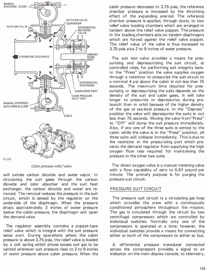
OUTFLOW VALVE
• OVERBOARD DISCHARGE
P-170
OUTFLOW VALVE
CABIN PRESSURE INLET PORT
Cabin pressure relief valve
wil l exhale carbon dioxide and water vapor. I n circulating the suit gases through the carbon dioxide and odor absorber and the suit heat exchanger, the carbon dioxide and water are removed. The removal reduces the pressu re in the suit circuit, which is sensed by the regu lator on the underside of the diaphragm. When the pressu re drops approximately 3 inches of water pressu re below the cabin pressu re, the diaphragm wil l open the demand valve.
The regulator assembly contains a poppet-type relief valve which is i ntegral with the suit pressu re sense port. During operations where the cabin pressu re is above 3. 75 psia, the relief valve is loaded by a coil spring which a l lows excess suit gas to be vented whenever suit pressu re rises to 2 to 9 inches of water pressu re above cabin pressu re. When the
cabin pressu re decreases to 3. 75 psia, the reference chamber pressure is increased by the throttl ing effect of the expanding aneroid. The reference chamber pressu re is applied, through ducts, to two relief valve loading chambers which are arranged in tandem above the relief valve poppet. The pressu re i n the loading chambers acts on tandem diaphragms which are forced against the relief valve poppet. The relief value of the valve is thus increased to 3. 75 psia plus 2 to 9 inches of water pressu re .
The suit test valve provides a means for pressurizing and depressu rizing the suit circuit, at controlled rates, for performing suit integrity tests. I n the "Press" position the valve supplies oxygen through a restrictor to pressu rize the suit circuit to a nominal 4 psi above the cabin in not less than 75 seconds. The max imum time req u i red for pressurizing or depressu rizing the suits depends on the density of the suit and cabin gases. It wi l l take longer to pressu rize or depressurize during prelaunch than in orbit because of the higher density of the gas at sea-level pressu re. I n the "Depress" position the valve wi l l depressu rize the suits in not less than 75 seconds. Moving the valve from"Press" to "Off" wil l dump the suit pressu re immediately. Also, if any one of the three su its is vented to the cabin wh ile the valve is in the "Press" position, a l l three suits wi l l collapse im mediately. This is due to the restrictor in the pressu rizing port which prevents the demand regu lator from supplying the h igh oxygen flow rate req u i red for maintaining the pressure in the other two suits.
The direct oxygen valve is a manual meteri ng valve with a flow capability of zero to 0.67 pou nd per minute. The primary purpose is for purging the pressure suit circuit.
PRESSURE S U I T CI RCUI T
The pressu re suit circuit i s a circulating gas loop which provides the crew with a continuously conditioned atmosphere throughout the m ission. The gas is c i rculated through the circuit by two centrifugal compressors which are control led by individual switches. Normally only one of the compressors is operated at a time; however, the individual switches provide a means for connecting either or both of the compressors to either ac bus.
A differential pressure transducer con nected across the compressors provides a signal to a n indicator o n the ma i n display console, to telemetry,
1 25

and to the caution and warning system, which wil l i l luminate a l ight at a differential pressure of 0.22 psi or less. Another differential pressure transducer is connected between the suit compressor inlet manifold and the cabin; the output is displayed on the indicator. A switch on the main display console selects the output of either transducer for display on the indicator. A pressure transducer connected to the compressor inlet manifold provides a signal to another ind icator and to telemetry.
The gas leaving the compressor flows through the carbon dioxide and odor absorber assembly. The assembly is a dual unit conta ining two absorber elements in separate compartments with inlet and outlet manifolds common to both. A diverter valve in the inlet manifold provides a means of isolating one compartment (without interrupting the gas flow through the suit circuit) to replace a spent absorber. An interlock mechanism between the diverter valve handle and the cover handles is intended to prevent opening both compartments at the same time. The absorber elements contain l ithium hydroxide and activated charcoal for removing carbon dioxide and odors from the suit gases. Orion pads on the inlet and outlet sides trap
small particles and prevent absorbent materials from entering the gas stream.
From the fi Iter the gas fl ows through the suit heat exchanger where the gases are cooled and the excess moisture is removed. The heat exchanger assembly is made up of two sets of broad flat tubes through which the coolant from the primary and secondary loops can be circulated. The coolant flow or bypass is control led by two valves located on the coolant control panel. The space between the tubes forms passages through which the suit gases flow. The coolant flowing through the tubes absorbs some of the heat from the suit gases. As the gases are cooled to about 550F, the excess moisture condenses and is removed from the heat exchanger by one or both of a pa ir of water accu mu lator pu mps.
The water accu mulators are piston-type pumps actuated by oxygen pressu re ( 1 00 psi) on the discharge stroke and by a return spring for the suction stroke. The oxygen flow is controlled by two water accumulator selector valve assemblies on the coolant control panel. Each valve assembly contains a selector valve, a solenoid valve, and an integral bypass. Oxygen flow can be controlled
CARBON DIOXIDE SENSOR 100±10 PSI �========================================�t-============��==� OXYGEN
-
FILTER
P-171
126
SUIT HOSE CDNNECTDRS.�-====�;m,l---' '----..._/
SUIT CIRCUIT RETURN AIR SHUTOFF
SUIT FLOW LIMITERS
SUIT TO CABIN c.P TRANSDUCER
SUIT COMPRESSORS
Simplified schematic of suit circuit
SUPPLY
DIRECT OXYGEN VALVE
WATER REMOVAL
IN PRIMARY WATER·Gl YCOL
OUT FLOW
IN SECONDARY WATER-GL YCDL
OUT FLOW
P = PRESSURE SENSOR T = TEMPERATURE SENSOR

IMPELLER
HOUSING
P-172
Suit compressor
MOTOR ROTOR ASSEMBLY
OESWI R L VANES
automatically by the solenoid valve through signals from the central t iming equ ipment. These signals will cause one of the accumulators to complete a cycle every ten m i nutes. I f it becomes necessary to cycle the accu mulators at more frequent intervals the solenoid valve can be controlled manual ly.
The cool gas ( 55°F nominal) flows from the heat exchanger through the suit flow l imiters and the flow control valves into the suits. The suit temperature is measured at the heat exchanger outlet, and is displayed on the ma in display console and telemetered .
A suit flow lim iter is installed in each suit supply duct to restrict the gas flow rate through any one suit. The flow l imiter is a tube with a Venturi section sized to l imit flow to 0.7 pound per minute. The l imiter offers maximum resistance to gas flow through a torn suit, when cabin pressure is near zero psia. The oxygen demand regu lator wi l l supply oxygen at flow rates up to 0.67 pou nd per minute
(for at least 5 minutes) to maintain pressure i n the circuit whi le the torn suit is being repaired.
F low control valves are part of the suit hose connector assembly. These valves prov ide a means for adjusting the gas flow through each suit individually. When operating in a sh irtsleeve environment with the inlet hose discon nected from the suit, approximately 1 2 cubic feet of suit gas per mi nute flows into the cabin.
A suit f low relief valve is installed between the suit heat exchanger outlet and the compressor in let, and is intended to maintain a relatively constant pressure at the inlets to the three suits by relieving transient pressure surges. A control is provided for manually c losing the valve; the valve is normally off throughout the mission.
SECONDARY WATER-GLYCOL I N LET
� I
PRIMARY WATER-GLYCOL INLET
MODULES
CONDENSING SURFACE WATER TRANSFER WICK (FEL TMETAL)
OXYG�N T:R:IN�' CORE DETAIL ( O N E MODULE SHOWN)
P-173 Suit heat exchanger
DISTRIBUTION MANIFOLD TO PARALLEL
127
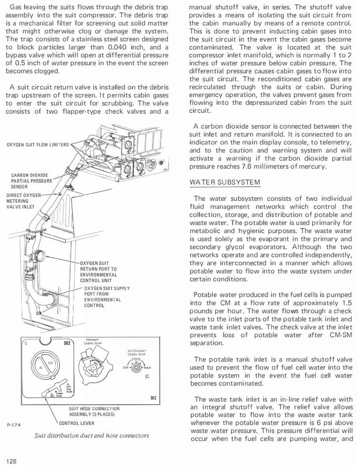
Gas leaving the suits flows through the debris trap assembly into the suit compressor. The debris trap is a mechanical filter for screening out solid matter that might otherwise clog or damage the system. The trap consists of a sta inless steel screen designed to block particles larger than 0.040 inch, and a bypass valve which wi l l open at differential pressu re of 0.5 inch of water pressure in the event the screen becomes clogged.
A suit circuit retu rn valve is installed on the debris trap u pstream of the screen. I t permits cabin gases to enter the suit circuit for scrubbing. The valve consists of two flapper-type check valves and a
OXYGEN SUIT FLOW LIMITERS
P-174
1 28
302
OXYGEN SUIT SUPPLY PORT FROM
ENVIRONMENTAL CONTROL
PRIMARY CAIIN TEMP
SECONDARY CABIN TEMP If�"
� (COCA
OFF��X
SUIT HOSE CONNECTION ASSEMBLY (3 PLACES)
li:J
Suit distribution duct and hose connectors
303
manual shutoff valve, in series. The shutoff valve provides a means of isolating the suit circuit from the cabin manual ly by means of a remote control. This is done to prevent inducting cabin gases into the suit circuit in the event the cabin gases become contaminated. The valve is l ocated at the suit compressor inlet manifold, which is normally 1 to 2 inches of water pressure below cabin pressu re. The differential pressure causes cabin gases to flow into the suit circuit. The reconditioned cabin gases are recirculated through the suits or cabin. During emergency operation, the valves prevent gases from flowing into the depressu rized cabin from the suit circuit.
A carbon dioxide sensor is connected between the suit inlet and return manifold. It is connected to an indicator on the ma in display console, to telemetry, and to the caution and warning system and wi l l activate a warning if the carbon dioxide partial pressure reaches 7.6 m i l l imeters of mercury.
WATER SU BSYSTEM
The water su bsystem consists of two individual fluid management networks which control the collection, storage, and distribution of potable and waste water. The potable water is used primarily for metabolic and hygienic purposes. The waste water is used solely as the evaporant i n the primary and secondary glycol evaporators. Although the two networks operate and are controlled independently, they are interconnected in a manner which al lows potable water to flow into the waste system under certain conditions.
Potable water produced in the fuel cel ls is pumped into the CM at a flow rate of approximately 1 .5 pounds per hour. The water flows through a check valve to the i nlet ports of the potable tank i nlet and waste tank i nlet valves. The check valve at the inlet prevents loss of potable water after CM-SM separation.
The potable tank inlet is a manual shutoff valve used to prevent the flow of fuel cell water into the potable system in the event the fuel cell water becomes contami nated.
The waste tank inlet is an in- l ine relief valve with an i ntegral shutoff valve. The relief valve al lows potable water to flow into the waste water tank whenever the potable water pressure is 6 psi above waste water pressure. This pressu re differential wi l l occur when the fuel cells are pumping water, and

either the potable water tank is fu l l , or the potable tank i nlet valve is closed; or when the waste water tank is completely empty and the glycol evaporators are demanding water for cooling. I n the latter case, the water flow is only that quantity which is demanded. The shutoff valve is used to block flow in case the relief valve fails. If such a fai l u re occurs, potable water can flow through the valve (provided the potable water pressure is higher than the waste) , unti l the two pressures are equal . Reverse flow is prevented by a check valve.
I n the event that both water tanks are fu I I at the time the fuel cel ls are pumping, the excess potable water wi l l be du mped overboard through a pressure relief valve. This is a dual u nit with a selector valve for placing either or both relief valves on-stream or shutting the u n it off.
Water flows from the control panel to the potable water tank, the food preparation water u n it, and
TO PRIMARY & SECONDARY WATER CONTROL VALVES
167 LB/HR WATER GL YCDL FLOW
WATER PRESSURE RELIEF r - - - - -:�
WASTE WATER TANK
FILTER
BLEED LINE
the water chi l ler. Chi l led water is del ivered to the food preparation water unit and to the drinking water dispenser through the drinking water supply valve.
The water chi l ler cools and stores 0.5 pound of potable water for crew consumption. The water chi l ler is designed to supply 6 ou nces of 50°F water every 24 minutes. The un it consists of an interna l ly baffled reservoir contain ing a coiled tube assembly which is used as the coolant conduit. The baffles are used to prevent the incoming hot water from mixing with and raising the temperature of the previously chil led water.
The food preparation water u nit heats potable water for use by the crew and a l lows manual selection of hot or cold potable water; the cold potable water is supplied by the water chi l ler. The unit consists of an electrically heated water reservoir and two manually operated valves which meter
WASTE TANK INLET VALVE
ORIFICE
COMMAND MODULE
VALVE
SERVICE MODULE
FUEL CELL WATER SUPPLY
CHLORINE INJECTION
CHECK VALVE
WATER CHILLER
TO DRINKING FIXTURE
r - - - - - - - -1 FOOD
- . I I
P-175
1 PR EPARATI 0 N 1 WATER UNIT I
;- WATER HEATER
I I
_ _ _ _ _ _j
Schematic of water management subsystem
T = TEMPERAT U R E SENSOR Q = QUANTITY SENSOR
1 29

P-176
GLYCOL OUTLET
0
0 GLYCOL I N LET
Water chiller
INSULATION
WARM WATER
INLET
CHILLED
WATER OUTLET
water in 1 -ou nce increments. The insulated reservoir has a capacity of 2.5 pounds of water. Thermostatically control led heating elements in the reservoir heat the water and maintain it at 1 540f nominal. Two metering valves dispense either hot or cold water, in 1 -ounce i ncrements, through a common nozzle. The hot water del ivery rate is approx imately 1 0 ounces every 30 mi nutes.
The drinking water supply valve is used to shut off the flow of water to the drinking water dispenser (water pisto l ) , in case of a leak in the flex hose.
The waste water and potable water are stored in positive expulsion tanks, which with the exception of capacity are identical in function, operation, and design. The positive expulsion feature is obtained by an integra l ly supported bladder, instal led longitudinally in the tank. Water collector channels, integral with the tank wa lls, prevent water from
1 30
being trapped within the tank by the expanding bladder. Quantity transducers provide signals to an indicator on the ma in display console.
Bacteria from the waste water system can migrate through the isolating valves into the potable water system . A syringe injection system provides for periodic injection of bactericide to k i l l bacteria in the potable water system .
Waste water extracted from the suit heat exchanger is pu mped into the waste water tank, and is delivered to the evaporator control valves. When the tank is fu l l , excess waste water is dumped overboard through the water pressure relief valve. The evaporator control valves consist of a manual ly operated inlet valve and a solenoid valve. The primary solenoid valve can be controlled automatical ly or manually. The secondary solenoid valve is controlled automatical ly.
0.5 VOLT OUTPUT PROPORTIONAL WATER QUANTITY
WATER OUT
P-177
TANK
Waste water tank

WATE R-G LYCO L COOLANT SU BSYSTEM
The water-glycol coolant subsystem consists of two independently operated closed coolant loops. The primary loop is operated continuously throughout the mission unless damage to the equipment necessitates shutdown. The secondary loop is operated at the discretion of the crew, and provides a backup for the primary loop. Both loops provide cooling for the suit and cabin atmospheres, the electronic equipment, and a portion of the potable water supply. The primary loop also serves as a source of heat for the cabin atmosphere when required.
The coolant is circulated through the loops by a pumping unit consisting of two pumps, a full-flow fi lter, and an accumulator for the primary loop, and a single pump, f i lter, and accumu lator for the secondary loop. The purpose of the accu mulators is to maintain a positive pressure at the pump inlets by accepting volu metric changes due to changes in coolant temperature. If the primary accumulator leaks, it can be isolated from the loop. Then the reservoir must be placed in the loop to act as an accumu lator. Accumulator quantity is d isplayed on the main display console. A switch on the console permits either of the pumps to be connected to either ac bus. The secondary permits either of the pumps to be connected to either ac bus. The secondary pump also has a switch which a l lows it to be connected to either ac bus.
The output of the primary pump flows through a passage in the evaporator steam pressure control valve to de-ice the valve throat. The coolant next flows through a diverter valve, through the radiators, and returns to the CM. The diverter valve is placed i n the "Bypass" position before lau nch to isolate the radiators from the loop, and before CM-SM separation to prevent loss of coolant when the CSM umbi l ical is cut. Otherwise it is in the normal operating position.
Coolant returning to the CM fl ows to the glycol reservoir va lves. From pre-launch unti l after orbit insertion, the reservoir in let and outlet valves are open and the bypass valve is closed, al lowing coolant to circulate through the reservoir. This provides a quantity of cold coolant to be used as a heat sink during the early stage of launch. After orbit insertion, the reservoir is isolated from the primary loop to provide a reserve supply of coolant for ref i l l ing the loop in the event a leak occu rs.
METAL BELLOWS ASSEMBLY
WATER·GL YCOL INLET (SECONDARY)
P-178
CABIN PRESSURE WATER-GLYCO L REFERENCE I N LET (PRIMARY)
I I I F L U I O ACCUM ULATOR
CUMULATOR
MOTOR
I N N E R MAGNET (ORIVEN)
Water-glycol pump assembly
The coolant flow from the evaporator divides into two branches. One carries a flow of 33 pou nds per hour to the inertial measurement u n it and into the coldplate network. The other branch carries a flow of 1 67 pou nds per hour to the water chi l ler through the suit heat exchanger primary glycol valve and the suit heat exchanger to the primary cabin temperature control valve.
The primary cabin temperature control valve routes the coolant to either the cabin heat exchanger or to the coldplate network. The valve is positioned automatica l ly by the cabin temperature control, or manual ly by means of an override control on the face of the valve. The valve is so constructed that in the cabin fu l l cooling mode, the flow of coolant from the suit heat exchanger ( 1 67 pounds per hour) is routed first through the cabin heat exchanger and then through the thermal coldplates where it joins with the flow (33 pounds per hour) from the inertial measu rement u n it. I n the cabin fu ll heating mode, the total flow (200 pounds per hour) is routed through the thermal coldplates f irst, where the water-glycol absorbs heat; from there it f lows through the cabin heat exchanger. I n the intermediate valve position, the quantity of cool or warm water-glycol flowing through the heat exchanger is reduced in proportion to the demand for cooling or heating. Although the amount of water-glycol flowing
131

through the cabin heat exchanger wi l l vary, the total flow through the thermal coldplates wi l l always be total system flow. A n orifice restrictor is installed between the cabin temperature control valve and the inlet to the coldplates. Its pu rpose is to maintain a constant flow rate through the coldplates by reducing the heating mode flow rate to that of the cooling mode flow rate. Another orifice restrictor, located in the coolant l i ne from the inertial measurement unit, maintains a constant flow rate through this component regardless of system flow fluctuations. The total flow leaving the primary cabin temperature valve enters the primary pump and is recirculated.
The output of the secondary pump flows through a passage in the secondary evaporator steam pressure control valve for de-icing the valve throat. The coolant next f lows through a d iverter valve, through the radiators, and retu rns to the CM. This valve also is placed in the bypass position before CM-SM separation to prevent loss of coolant when the CSM u mbi l ical is severed. After retu rning to the CM the coolant fl ows through the secondary evaporator,
the suit heat exchanger secondary glycol valve, and the suit heat exchanger to the secondary cabin temperature control valve. The secondary cabin temperature control valve regu lates the quantity of coolant flowing through the cabin heat exchanger in the cooling mode (there is not heating capability in the secondary loop). The coolant from the secondary cabin temperature control valve and/or the cabin heat exchanger then flows through redu ndant passages in the coldplates and returns to the secondary pump inlet.
The heat absorbed by the coolant in the primary loop is transported to the radiators where a portion is rejected to space. I f the quantity of heat rejected by the radiators is excessive, the temperature of the coolant retu rning to the CM wil l be lower than desired (45°F nomi nal ) . I f the temperature of the coolant entering the evaporator drops below a nominal 43°F, the mixing mode of temperature control is initiated. The automatic control opens the glycol evaporator temperature valve, which al lows a sufficient quantity of hot coolant from the pump to mix with the coolant retu rning from the
STEAM PRESSURE
CONTROL
PRIMARY
HEAT EXCHANGER
SECONDARY SUIT
HEAT EXCHANGER
PRIMARY SUIT
HEAT EXCHANGER
SECONDARY
HEAT EXCHANGER
P-179
1 32
WATER
VALVE
T TEMPERATURE SENSOR
P PRESSUR E SENSOR
0 QUANTITY SENSOR
F FLOW RATE
VALVE
COMMAND MODULE
Schematic of primary water-glycol subsystem
SERVICE MODULE
SPACE RADIATOR
ISOLATION
VALVES (41

PRIMARY G LYCOL ACCUMULATOR QUANTITY TRANSDUCER
SECONDARY PUMP PRESSURE TRANSDUCER
PRIMARY PUMP PRESSURE TRANSDUCER
PRIMARY GLYCOL I N LET
SECONDARY
SECONDARY SYSTEM MOTOR
SECONDARY
ACCUMULATOR QUANTITY
SECONDARY GLYCO L I N LET
PRIMARY GLYCOL OUTLET
P-180 Glycol pump assembly
radiators to produce a mixed temperature at the inlet to the evaporator between 43° and 48°F. There is no mixing mode in the secondary loop: I f the temperature of the coolant retu rning from the secondary radiator is lower than 45°F nominal, the secondary radiator inlet heater wi l l be turned on to maintain the outlet temperature between 420 and 480F.
If the radiators fail to radiate a sufficient quantity of heat, the coolant retu rning to the CM wi l l be above the desired temperature. When the temperature of the coolant entering the evaporator rises to 480 to 5Q. 50F, the evaporator mode of cooling is initiated. The glycol temperature control opens the steam pressure valve allowing the water in the evaporator wicks to evaporate, using some of the heat contained in the coolant for the heat of vaporization. A temperature sensor at the outlet of the evaporator controls the position of the steam pressure valve to establish a rate of evaporation that wi l l result in a coolant outlet temperature between 400 to 430F. The evaporator wicks are maintained in a wet condition by wetness control which uses the wick temperature as an indication of water content. As the wicks become dryer, the wick temperature increases and the water control valve is opened. As the wicks become wetter, the wick temperature decreases and the water valve closes. The evaporative mode of cooling is the same for both l oops. The steam pressure valve can be
controlled remotely, using evaporator outlet temperature as an indicator. The secondary evaporator is controlled automatically.
Each coolant loop includes a radiator circuit. The primary radiator circuit consists basically of two radiator panels in paral le l with a flow-proportioning control for dividing the flow between them, and a heater control for adding heat to the loop. The secondary circuit consists of a series loop uti l izing some of the area of both panels, and a heater control for adding heat to the loop.
The radiator panels are an integral part of the SM skin and are located on opposite sides of the SM in Sectors 2 and 3 and in Sectors 5 and 6. With the radiators being diametrically opposite, it is possible that one primary panel may face deep space while the other faces the sun, earth, or moon. These
EXPULSION BLADDER
P·l81
WATER-G LYCOL I N
Water-glycol reservoir
WATE R-GLYCOL O U T
GAS I N
1 33

extremes in environments mean large differences in panel efficiencies and outlet temperatures. The panel facing deep space can reject more heat than the panel receiving external radiation; therefore, the overall efficiency of the subsystem can be improved by increasing the flow to the cold panel. The higher flow rate reduces the transit time of the coolant through the radiator, which decreases the quantity of heat radiated.
The flow through the radiators is controlled by a flow-proportioning valve. When the differential temperature between the outlets of the two panels exceeds 1 0° F , the flow-proportioning valve is positioned to increase the flow to the colder panel.
The flow-proportioning valve assembly contains two individually controlled va lves, only one of which can be in operation. When the switches are
CONTACT SPONGE WATER TRANSFER WICK
SENSOR REDISTRIBUTION WATER PAD
GLYCOL INLET PORT
@ SENSOR DETAIL SENSOR ELECTRICAL CONNECTOR
MANIFOLD TO
PARALLEL MODU LES 'N HEATER I STEAM FINS EVAPORATE WATER
SING LE-PASS HEAT EXCHANGER MODULE
TWO-PASS HEAT
EXCHANGER MODULE
WATER DISTRIBUTION LINES
DISTR IBUTION SPONGES
P-182 Glycol evaporator
1 34
P·l83
Cabin heat exchanger
OXYGEN " OUTLET
PROTECTIVE SCREEN
on automatic the flow controller selects the No. 1 valve and positions the appropriate radiator isolation valves. Manual selection and transfer also is possible. Automatic transfer wi l l occur when the temperature differential exceeds 1 5°F, providing a failure has occurred. I n the absence of a fai lure, the transfer signal wi I I be inh ibited. I n situations where the radiator inlet temperature is low and the panels have a favorable environment for heat rejection, the radiator outlet temperature starts to decrease and thus the bypass ratio starts to increase. As more flow is bypassed, the radiator outlet temperature decreases u nti l the -2QOf minimu m desired temperature wou ld be exceeded. To prevent this from occurring, a heater is automatical ly turned on when

radiator mixed outlet temperature drops to - 1 5° F and remains on until - 1 0° F is reached. The controller provides only on-off heater control which resu lts in a nominal 450 watts being added to the coolant each time the heater is energized. The crew can switch to a redu ndant heater system if the temperature decreases to -20°F.
If the radiator outlet temperature falls below the desired minimum, the effective radiator surface temperature wi l l be controlled passively by the selective stagnation method. The two primary circuits are identical, consisting of five tubes in para l lel and one downstream series tube. The two panels, as explai ned in the flow proportioning control system, are in paral lel with respect to each other. The five parallel tubes of each panel have manifolds sized to provide specific flow rate ratios in the tubes, nu mbered 1 through 5. Tube 5 has a lower flow rate than Tube 4, and so on, through Tube 1 which has the highest flow. For equal fin areas therefore the tube with the lower flow rate wi l l
'have a l;wer coolant temperature. During
minimum CM heat loads, stagnation begins to occur in Tube 5 as its temperature decreases; for as its t e m p e r a t u r e decreases, the flu id resistance increases, and the flow rate decreases. As the fin area around Tube 5 gets colder, it draws heat from Tube 4 and the same process occurs with Tube 4. I n a fu l ly stagnated condition, there is essent ial ly no flow in Tubes 3, 4, and 5, and some flow in Tubes 1 and 2, with most of it in Tube 1 .
When the CM heat load increases and the radiator inlet starts to increase, the temperature in Tube 1 increases and more heat is transferred through the fin toward Tube 2. At the same time, the glycol evaporator temperature valve starts to c lose and force more coolant to the radiators, thus helping to thaw the stagnant portion of the panels. As Tube 2 starts to get warmer and receives more flow it in turn starts to thaw Tube 3, and so on. This combination of h igher in let temperatures and higher flow rates quickly thaws out the panel. The panels automatica l ly provide a high effectiveness (completely thawed panels operating at a high average fin temperature) at high heat loads, and a low effectiveness (stagnated panels operating at a low average fin temperature) at low heat loads.
The secondary radiator consists of four tubes which are an integral part of the radiator panel structure. Each tube is purposely placed close to the hottest primary radiator tubes ( i.e., Tube 1 and
ISOLATION VALVES (4 EA)
P·184 INLET
Space radiator flow proportioning valves
the downstream series tube on each panel) to keep the water-glycol i n the secondary tu bes from freezing wh ile the secondary circuit is inoperative. The selective stagnation principle is not util ized i n the secondary radiator because of the narrower heat load range requ irements. This is also the reason the secondary radiator is a series loop. Because of the lack of this passive control mechanism, the secondary circuit depends on the heater control system at low heat loads and the evaporator at high heat loads for control of the water-glycol temperature.
The secondary heaters differ from the primary in that they can be operated simultaneously. When the secondary outlet temperature reaches 43°F the No. 1 heater comes on, and at 42°F the No. 2 heater comes on; at 440F No. 2 goes off, and at 45°F No. 1 goes off.
135

r - - - - ----'-
1 .--- - -_ _ _ _ _ j -W- - - - - - - - -
1'1t1Mt�f( !CS ••04•101 If"" ttiM �
TO PRIMA
-
GLYCOL t0Y0�ATER·
TO SECOND G LYCO L LO��Y WATER·
P-185
136
I I I I I I --� I I I I I I I I I I
SECONDARY SYSTEM F I L L
Schematic 1 o radiator sub system
NO. 1 FLOW PR 0 PO RTI 0 N I N G VALVE