Embed Size (px)
Citation preview

Hao Zhu
Dept. of Electrical & Computer Engineering University of Illinois, Urbana-Champaign
Distribution System Voltage Control under Imperfect Communications
PSERC Webinar September 15, 2015

Voltage control
Ideally, we all want to plug into a constant voltage source at 120V
Voltage control/stability in bulk transmission grid more closely related to reactive power (VAR) load balance – Fast decoupled power flow (FDPF) model
Real power could also affect voltage fluctuations in distribution systems because of the higher r/x ratio
2
Cartoon: W-R-O-N-G Voltagggeeee for a vintage machine like Myself [Source: jantoo.com]

126V
114V
Voltage
Voltage control in distribution systems
Typical control devices: load tap changer (LTC) transformers, voltage regulators, and capacitor banks
3
LTC Xformer Voltage Regulators

Load tap changer (LTC)
A selector switch device attached to power transformers
To maintain a constant low-side or secondary voltage with a variable primary voltage supply
Or to hold a constant voltage out along the feeders on the low-voltage side for varying load conditions
Also termed as tap changing under load (TCUL) transformers
4
"Tap changing switch" by BillC at English Wikipedia
[Gonen’s book, 2014]

Voltage regulators and capacitors
Voltage regulators: induction devices in shunt or series with regulated circuit for the control of its voltage
Capacitors: perform power factor correction with additional switching and protective elements
5
[Gonen’s book, 2014]

Volt/Var control (VVC)
Traditional VVC relies on individual, independent, stand-alone control devices that react to local measurements
Challenged by rapid changes in distribution loads due to penetration of distributed generations and electric vehicle charging 6
Source: EPRI Smart Grid Demo

An example
Real power injection increases local voltage Non-decreasing voltage profile due to DG outputs
7
126V
114V
Voltage
LTC Xformer Voltage Regulators
High PV Output

Centralized VVC An integrated approach that computes and executes coordinated
control for all devices [Cf. optimal power flow (OPF)] Enabled by two-way communications between a centralized
controller and remote meters/devices
8
Source: Eaton Yukon IVVC solution

Additional VAR sources
DGs/battery devices also offer new venues for VAR support
Synchronous generation: exciter control Inverter-connected devices: VAR control [Lopes et al '07],[Turitsyn et al '11]
Most of these VAR sources currently operated
under fixed power factor
9

Optimal voltage control
10
OPF problem formulation [Farivar et al '12] [Zhang et al '15] A two-stage approach of slow/fast time-scales [Robbins et al '13] (De-)centralized solvers for three-phase systems [Dall’anese-Zhu-
Giannakis’13]
minimize Power losses + Load demand + VAR costs
subject to 𝑉𝑉 ≤ 𝑉𝑉 ≤ 𝑉𝑉 𝑃𝑃𝑔𝑔 ≤ 𝑃𝑃𝑔𝑔 ≤ 𝑃𝑃𝑔𝑔
𝑄𝑄𝑔𝑔 ≤ 𝑄𝑄𝑔𝑔 ≤ 𝑄𝑄𝑔𝑔
Power flow equations Convex relaxation
E. Dall’Anese, H. Zhu, and Georgios B. Giannakis, “Distributed Optimal Power Flow for Smart Microgrids,” IEEE Trans. Smart Grid, Sep. 2013.
Voltage regulation
DG limit constraints

Optimal transformer tap control An OPF approach to optimize three-phase transformer taps A virtual-bus based transformer model (De-)centralized solvers using convex relaxation
11 B. A. Robbins, H. Zhu, and A. D. Domínguez-García, “Optimal Setting of the Taps of Voltage Regulation Transformers in Distribution Systems,” IEEE Trans. Power Systems , 2015.
minimize Power losses + operational costs
subject to 𝑉𝑉 ≤ 𝑉𝑉 ≤ 𝑉𝑉 𝑎𝑎𝑉𝑉𝑝𝑝 ≤ 𝑉𝑉𝑠𝑠 ≤ 𝑉𝑉𝑝𝑝𝑎𝑎
Power flow equations
Tap constraints
Convex relaxation
Voltage regulation

Alternative approaches
Adaptive control: sequentially updates the DG VAR output at each bus [Yeh et al '12]
A model predictive control (MPC) framework [Valverde et al '13], [Wang et al '14] – Coordinated management of DG real/reactive power generation and
transformer tap positions
12

Stochastic control Stochastic-approximation VVC method that deals with system
uncertainty and measurement noise [Bazrafshan et al '14], [Kekatos et al '15]
A dual-subgradient approach that accounts for the dynamics/ delay in updating inverter control setpoints [Dall’anese et al '15]
13 E. Dall'Anese, S. V. Dhople, and G. B. Giannakis, “Photovoltaic Inverter Controller Seeking AC Optimal Power Flow Solutions,” IEEE Trans. on Power Systems, to appear. [Online] Available at: http://arxiv.org/abs/1501.00188

Summary of centralized VVC
14
With all information available, centralized decision-making can improve the overall system operations
But it requires high-quality high-throughput two-way communications to remote devices
Communication failures/delays can result in suboptimal and instable control, especially for distribution systems with rapid load variations and intermittent DGs
1. Local VVC at no communication requirements 2. Distributed VVC resilient to communication link failures

Fast local inverter VAR control At no communications, inverters can determine VAR
outputs based on local bus voltage magnitudes – Can quickly and accurately respond to voltage
violations
Droop control (IEEE 1547.8) [Farivar et al '13]
– Instability arises under high PV penetration [Jahangiri et al '13] – Integral control at unlimited inverter VAR [Zhang et al '12], [Li et al '14]
15

Instable droop control
A radial 16-bus single-phase case with r/x ratio ≈ 0.635 Bus loading ~ (70+j30)kVA; abundant VARs (±100kVar)
16 5 10 15 20 250.02
0.04
0.06
0.08
0.1
0.12
0.14
0.16
0.18
0.2
0.22
Iteration Index
||V-1
||
DroopGPDelayed GPDelayed DroopCentralizedBenchmark

Matrix LinDistFlow model
17
is the power network B bus matrix (dc power flow) Equivalent to fast decoupled power flow (FDPF) model

Gradient-Projection (GP) based VAR control
18
minimize Weighted V mismatch + VAR costs
subject to 𝑞𝑞𝑗𝑗 ≤ 𝑞𝑞𝑗𝑗 ≤ 𝑞𝑞𝑗𝑗 at every bus j
Optimal GP iteration
Quadratic
Vj GP
qj D

Features of GP-based local control
Droop control: setting – 𝑐𝑐𝑗𝑗 has to be large enough to ensure stability [Farivar et al '13] – A delayed + droop scheme in [Jahangiri et al '13]
19
Requiring minimal coordination with control center − GP-based control can be stabilized with any arbitrary 𝑐𝑐𝑗𝑗
Generalizing unbalanced (three-phase) distribution networks
Allowing for asynchronous control updates (plug-and-play)

Static system tests A radial 16-bus single-phase case with r/x ratio ≈ 0.635 Bus loading ~ (70+j30)kVA; abundant VARs (±100kVar) NOTE: voltage obtained by solving ac power flow (not the linearized model)!
20 5 10 15 20 250.02
0.04
0.06
0.08
0.1
0.12
0.14
0.16
0.18
0.2
0.22
Iteration Index
||V-1
||
DroopGPDelayed GPDelayed DroopCentralizedBenchmark

Asynchronous updates Each bus randomly updates every 𝑡𝑡 ∈ [1,𝑇𝑇] iterations Guaranteed to converge; larger 𝑇𝑇 slows down convergence speed
21

Dynamic system tests Daily profile of residential load and solar PV output every minute Heavy loading during the evening (18:00-22:00) High solar variability in the afternoon (12:00-17:00)
Source: https://archive.ics.uci.edu/ml/datasets/Individual+household+electric+power+consumption
22
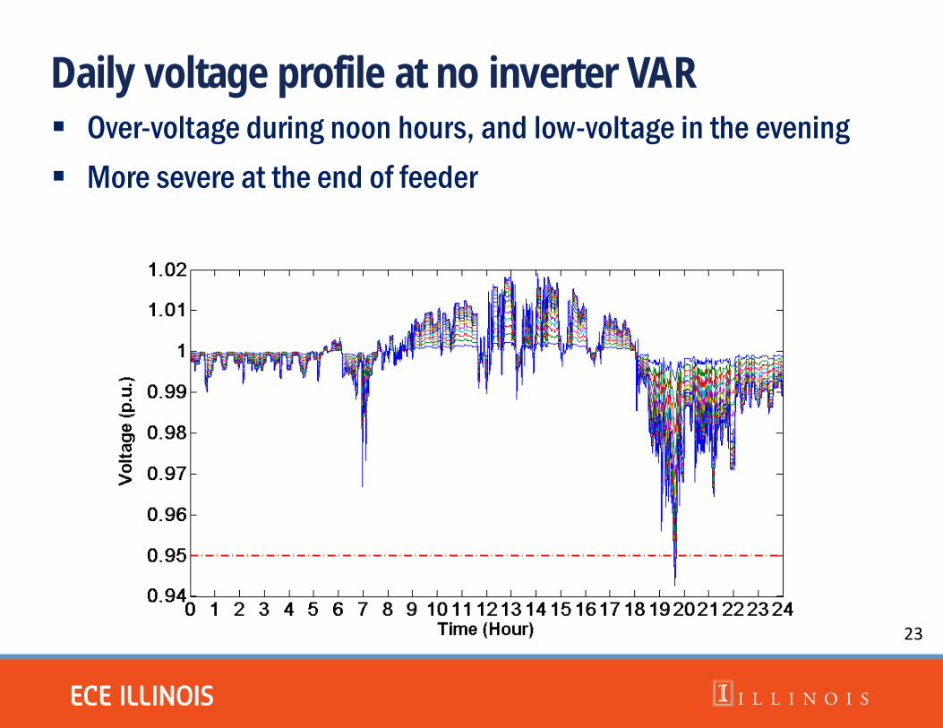
Daily voltage profile at no inverter VAR Over-voltage during noon hours, and low-voltage in the evening More severe at the end of feeder
23

Dynamic VAR control Local VAR control updates every 5 seconds Proposed GP-based scheme effectively reduce voltage mismatch
24 0 2 4 6 8 10 12 14 16 18 20 22 240
0.02
0.04
0.06
0.08
0.1
0.12
0.14
0.16
Time (Hour)
||V-1
||
No VARGPDelayed Droop
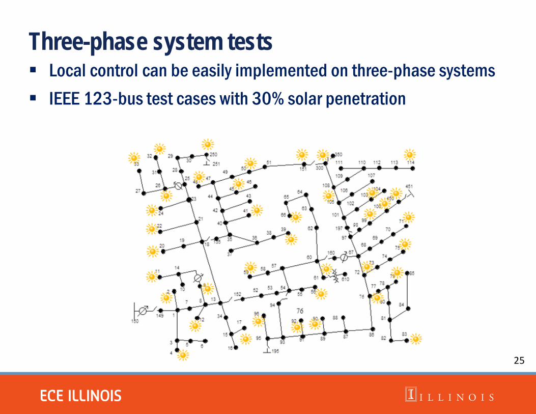
Three-phase system tests Local control can be easily implemented on three-phase systems IEEE 123-bus test cases with 30% solar penetration
25

Three-phase voltage profile
Actual voltage profile obtained using OpenDSS – Phase a: black; Phase b: red; Phase c: blue
Volta
ge (p
.u.)
Distance from substation 26

Dynamic voltage mismatch
Local control less effective under low solar penetration level
27 0 2 4 6 8 10 12 14 16 18 20 22 240
0.05
0.1
0.15
0.2
0.25
0.3
0.35
0.4
0.45
Time (Hour)
||Va-
1||
No VARGPDelayed droop
18 19 20 21 22
0.1
0.2
0.3
0.4
Need communications to share information globally!

Drawbacks of local control
It minimizes a weighted mismatch norm, instead of
28
minimize Weighted V mismatch + VAR costs
subject to 𝑞𝑞𝑗𝑗 ≤ 𝑞𝑞𝑗𝑗 ≤ 𝑞𝑞𝑗𝑗 at every bus j
Global objective: unweighted voltage mismatch norm
minimize V mismatch + VAR costs
subject to 𝑞𝑞𝑗𝑗 ≤ 𝑞𝑞𝑗𝑗 ≤ 𝑞𝑞𝑗𝑗 at every bus j

Distributed VAR control
Key of parallelization lies in the structure of
Power flow constraint at bus 𝑗𝑗 just involves its neighboring buses Distributed solver (ADMM): communications between one-hop
neighboring buses
Also holds for unbalanced three-phase systems
29

Communication Links
Voltage variable update at node j
VAR variable update at node j
Voltage variable and measurement from neighbors
Coupling voltage variables to neighbors
Coupling voltage variables from neighbors
VAR control input at node j
Voltage variable and measurement to neighbors
30

Features of distributed control
Simple local computation tasks: linear /QP updates Implemented online by incorporating dynamic voltage measurement
– Neighboring buses only exchange voltage variables – Existing methods collect/exchange real/reactive power measurements [Sulc et al '14], [Robbins et al '15]
Extended to unbalanced three-phase systems Asynchronous updates guaranteed to converge [Lutzeler et al ' 13]
31

Static system tests
The same 16-bus single-phase case with r/x ≈ 0.635 Various VAR provision cost coefficients 𝑐𝑐
32 0 10 20 30 40 500
0.01
0.02
0.03
0.04
0.05
Iteration Index
||v-1
||
c=0.01c=0.04c=0.08c=0.1c=0.15

Asynchronous updates
Each link randomly fails with given probability 1 𝒩𝒩𝑗𝑗�
33 0 100 200 300 400 500 600 700 800 9000
0.005
0.01
0.015
0.02
0.025
0.03
0.035
0.04
0.045
0.05
Iteration Index
||v-1
||
Asynchronous ADMMSynchronous ADMM

Dynamic tests for the 123-bus system Both local and distributed methods update every 3 seconds Distributed control more effectively reduces voltage mismatch
0 1 2 3 4 5 6 7 8 9 10 11 12 13 14 15 16 17 18 19 20 21 22 23 240
0.1
0.2
0.3
0.4
0.5
0.6
Time (Hour)
||va-
1||
Delayed DroopADMMNo VAR
15 16 17 18 19 20 21 220
0.1
0.2
0.3
0.4
0.5
Time (Hour)
||va-
1||
34

Conclusions
Distribution system voltage control challenged by increasing load variations and intermittent DG output
GP-based local control tackles the instability of droop control Distributed control seeks the globally optimal solution Both applicable to unbalanced systems and imperfect
update/communication scenarios Future research: how does it interact with LTC or other devices?
35

Acknowledgements Collaboration work with UIUC student H.-J. (Max) Liu and
colleagues Drs. Alejandro Dominguez-Garcia and B. Robbins (now at PC Krause), as well as former UMN colleagues, Drs. E. Dall’anese (now at NREL) and G. B. Giannakis; also discussions with Dr. George Moustakides (Rutgers U.)
Support from Illinois Center for a Smarter Electric Grid (ICSEG), Trustworthy Cyber Infrastructure for the Power Grid (TCIPG), PSERC, and ABB research grant program
36