Embed Size (px)
Citation preview
7/27/2019 Electrical Marine Rules Comparison
http://slidepdf.com/reader/full/electrical-marine-rules-comparison 1/11
Industrial Power Systems, Inc.3010 Powers Ave Suite 16 Jacksonville, Florida 32207
www.ipsswitchgear.com [email protected]
Phone: 904.731-8811 Fax: 904-731-0188
Marine Regulatory Agency, Low VoltageSwitchboard Components, Rules Comparison
US Department of Homeland Security, US Coast Guard, Title 46 Shipping,
Volume 4, Chapter I, Subchapter J, Part 111
American Bureau Of Shipping (ABS) Publication #2, Rules for Building and
Classing Steel Vessel Rules 2009, Part 4, Chapter 8
American Bureau Of Shipping (ABS) Publication #5, Steel Vessels Under 90 Meters
(295 Feet) in Length, Part 4, Chapter 5
IEEE45-2002 Recommended Practice for Electric Installations on Shipboard
Compiled by John Winbery © Copyright 2009 Industrial Power Systems, Inc
7/27/2019 Electrical Marine Rules Comparison
http://slidepdf.com/reader/full/electrical-marine-rules-comparison 2/11
.
INDUSTRIAL POWER SYSTEMS, INC
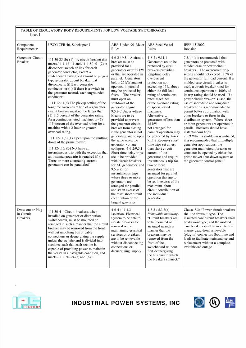
TABLE OF REGULATORY BODY REQUIREMENTS FOR LOW VOLTAGE SWITCHBOARDS
Sheet 1
Component
Requirements:
USCG CFR 46, Subchapter J ABS Under 90 Meter
Rules
ABS Steel Vessel
Rules
IEEE-45 2002
Revision
Generator Circuit
Breaker 111.30-25 (b) (1) “A circuit breaker thatmeets § 111.12–11 and § 111.50–5 (2) A
disconnect switch or link for each
generator conductor, except a
switchboard having a draw-out or plug-in
type generator circuit breaker that
disconnects: (i) Each generator
conductor; or (ii) If there is a switch in
the generator neutral, each ungrounded
conductor.
111.12-11(d) The pickup setting of the
longtime overcurrent trip of a generator
circuit breaker must not be larger than:
(1) 115 percent of the generator rating
for a continuous rated machine; or (2)
115 percent of the overload rating for a
machine with a 2-hour or greater
overload rating.
111.12-11(c) (1) Open upon the shuttingdown of the prime mover;
111.12-11(c)(3) Not have an
instantaneous trip with the exception that
an instantaneous trip is required if: (i)
Three or more alternating-currentgenerators can be paralleled”
4-6-2 / 9.3.1 A circuit
breaker must be provided for all
generators over 25 kW
or that are operated in
parallel. Generators
below 25 kW and not
operated in parallel
may be protected by
fuses. The breaker
must open on
shutdown of the
generator engine.
9.5.2(c)Undervoltage
Means are to be
provided to prevent
the generator circuit
breaker from closing
if the generator is not
generating and to open
the same when the
generator voltage
collapses. 4-6-2/9.5.1
Short-time delay trips
are to be provided
with circuit breakers
for AC generators. and
9.5.2(a) for
instantaneous trips
where three or more
generators arearranged tor parallel
and set in excess of
the max. short circuit
contribution of the
largest generator.
4-8-2 / 9.11.1
Generators are to be protected by circuit
breakers providing
long-time delay
overcurrent
protection not
exceeding 15% above
either the full-load
rating of continuous-
rated machines
or the overload rating
of special-rated
machines.
Alternatively,
generators of less than
25 kW
not arranged for
parallel operation may
be protected by fuses.
9.11.2 Requires short
time trips set at less
than short circuit
current of the
generator and require
instantaneous trip for
two or more
generators that are
arranged for parallel
operation that are to
be set in excess of themaximum short-
circuit contribution of
the individual
generator..
7.5.1 “It is recommended that
generators be protected withmolded case or power circuit
breakers. The overcurrent trip
setting should not exceed 115%
the generator full load current. If
molded case circuit breaker is
used, a circuit breaker rated for
continuous operation at 100% of
its trip rating should be used. If
power circuit breaker is used, the
use of short-time and long-time
breaker trips is recommended to
permit better coordination with
other breakers or fuses in the
distribution system. Where thre
or more generators are operated
parallel, breakers should have
instantaneous trips
7.5.9 When a shutdown is initiat
it is recommended that in multip
generator applications, the
generator main circuit breaker or
contactor be opened by either th
prime mover shut-down system
the generator control panel.”
Draw-out or Plug-
in Circuit
Breakers.
111.30-4 “Circuit breakers, when
installed on generator or distribution
switchboards, must be mounted or
arranged in such a manner that the circuit
breaker may be removed from the front
without unbolting bus or cable
connections or deenergizing the supply,
unless the switchboard is divided into
sections, such that each section iscapable of providing power to maintain
the vessel in a navigable condition, andmeets § 111.30–24 (a) and (b).”
4-6-4 / 11.1.3
Isolation. Electrical
System to be able to
isolate breakers for
removal while
maintaining essential
services or breakers
are to be removable
without disconnectingconnections or
deenergizing supply.
4-8-3 / 5.3.3(c)
Removable mounting .
“Circuit breakers are
to be mounted or
arranged in such a
manner that the
breakers may be
removed from the
front of theswitchboard without
first deenergizing
the bus bars to which
the breakers connect.”
Clause 8.3: “Power circuit break
shall be drawout type. The
insulated case circuit breakers sh
be drawout type, and the molded
case breakers shall be mounted o
marine dead-front removable
(plug-in) connectors (both line a
load) to facilitate maintenance an
replacement without a completeswitchboard outage.”

7/27/2019 Electrical Marine Rules Comparison
http://slidepdf.com/reader/full/electrical-marine-rules-comparison 3/11
.
INDUSTRIAL POWER SYSTEMS, INC
TABLE OF REGULATORY BODY REQUIREMENTS FOR LOW VOLTAGE SWITCHBOARDS
Sheet 2
Component Requirements: CFR 46, Subchapter J ABS Under 90 Meter
Rules
ABS Steel Vessel
Rules
IEEE-45 2002
Revision
Generator Pilot Light 111.30-25(b)(3) requires:
“A pilot lamp connected between the generator
and the circuit breaker.”
4-6-4 Table 7, Item 1
requires: “A pilotlamp for each
generator connected
between generator
and circuit breaker.”
4-8-3 Table 5, Item 1
requires: “Anindicator light for each
generator connected
between generator
and circuit breaker.”
Clause 7.6 requires: “An indicat
light permanently connected to tgenerator side of each generator
circuit breaker.”
Ammeter and Selector Switch 111.30-25(b)(4) requires:
“An ammeter with a
selector switch that
connects the ammeter to
show the current in each
phase.”
4-6-4 Table 7, Item 5
requires: “An ammeter
for each generator
with a selector switch
to read the current of
each phase.”
4-8-3 Table 5, Item 4
requires: Same as
under 90 meter rules.
Clause 7.5.10 requires “an
ammeter (with a selector switch
meter all phases)”
Clause 8.5 requires 1% accuracy
250 deg. scale analog switchboa
type or equal electronic
instruments.
Voltmeter and Selector Switch
.
111.30-25(b)(5) “A
voltmeter with a selector
switch that connects the
voltmeter to show the: (i)
Generator voltage of
each phase; and (ii) Busvoltage of one phase.”
111.30-25(f)(3): “(f)
For each shore power
connection each
switchboard must have:
(3) One of the voltmeters
under paragraph (b)(5) of
this section connected toshow the voltage of each
phase of the shore powerconnection”
4-6-4 Table 7, Item 6
requires: “A voltmeter
for each generator,
with a selector switch
to each phase of the
generator and to one
phase of the bus.”
4-8-3 Table 5, Item 5
requires: Same as
under 90 meter rules.
Clause 7.5.10 requires: “a
voltmeter, and a voltmeter select
switch (to provide metering of a
phases and one phase of bus
voltage, if applicable).” Clause
8.5 requires: “ All electrical
indicating instruments should be
switchboard-type or equivalent
electronic-type” The switchboa
type or electronic-type instrumen
should have 1% accuracy and, in
the case of switchboard type
analog instruments, preferably
have a 250° circular scale.”
Wattmeter 111.30-25 d) “If
generators are arranged
for parallel operation,
each switchboard must
have: (2) An indicating
wattmeter for eachgenerator.”
4-6-4 Table 7, “Where
generators are
arranged for parallel
operation, an
indicating wattmeter is
to be fitted for each
generator.”
4-8-3 Table 5, same as
under 90 meter rules.
Clause 7.5.10 requires: “For
generators intended for parallel
operation, the metering should b
as described in this subclause, an
in addition a wattmeter should b
installed.” Clause 8.5 also
requires 1% accuracy, 250 deg.
scale analog switchboard type or
equal electronic instruments. Se
quoted clause for voltmeter.
7/27/2019 Electrical Marine Rules Comparison
http://slidepdf.com/reader/full/electrical-marine-rules-comparison 4/11
.
INDUSTRIAL POWER SYSTEMS, INC
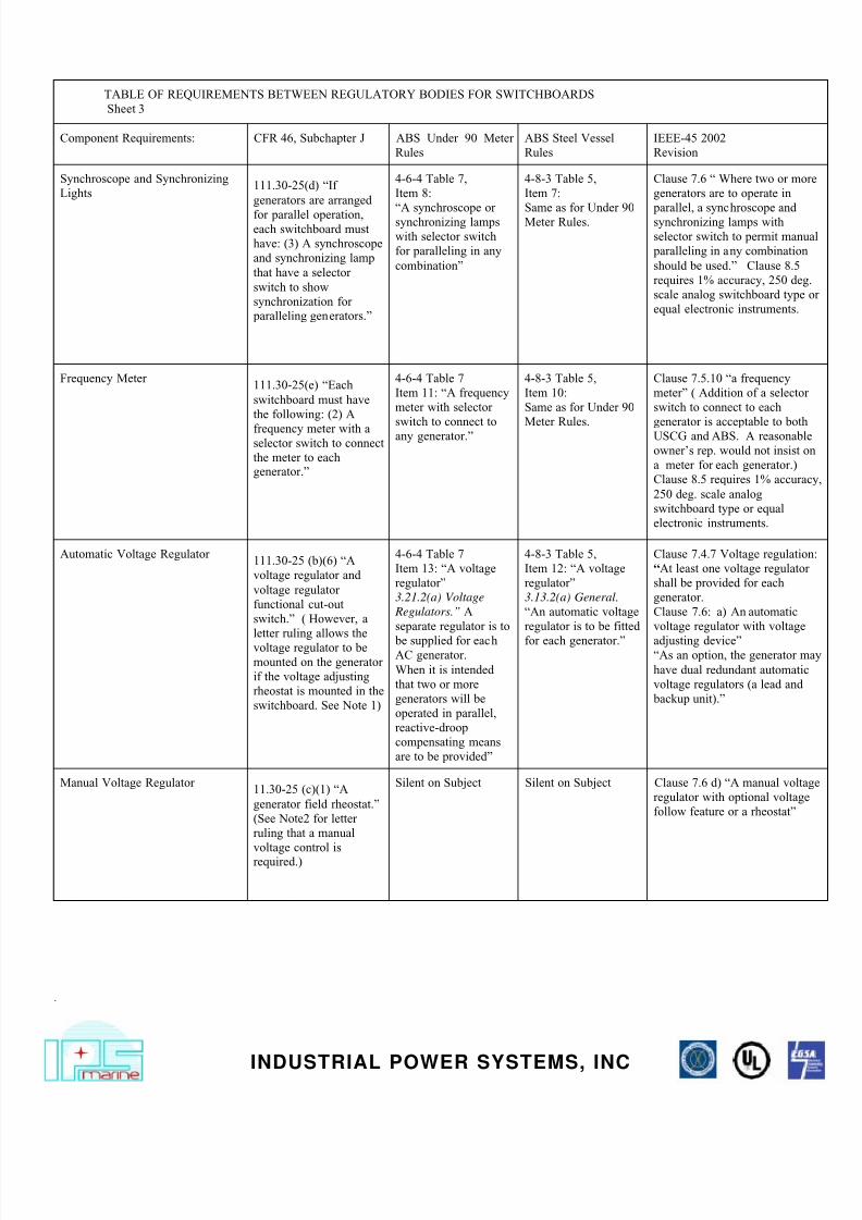
TABLE OF REQUIREMENTS BETWEEN REGULATORY BODIES FOR SWITCHBOARDS
Sheet 3
Component Requirements: CFR 46, Subchapter J ABS Under 90 Meter
Rules
ABS Steel Vessel
Rules
IEEE-45 2002
Revision
Synchroscope and Synchronizing
Lights111.30-25(d) “If
generators are arranged
for parallel operation,each switchboard must
have: (3) A synchroscope
and synchronizing lamp
that have a selector
switch to show
synchronization for
paralleling generators.”
4-6-4 Table 7,
Item 8:
“A synchroscope orsynchronizing lamps
with selector switch
for paralleling in any
combination”
4-8-3 Table 5,
Item 7:
Same as for Under 90Meter Rules.
Clause 7.6 “ Where two or mo
generators are to operate in
parallel, a synchroscope andsynchronizing lamps with
selector switch to permit manu
paralleling in any combination
should be used.” Clause 8.5
requires 1% accuracy, 250 deg
scale analog switchboard type
equal electronic instruments.
Frequency Meter111.30-25(e) “Each
switchboard must have
the following: (2) A
frequency meter with aselector switch to connect
the meter to eachgenerator.”
4-6-4 Table 7
Item 11: “A frequency
meter with selector
switch to connect toany generator.”
4-8-3 Table 5,
Item 10:
Same as for Under 90
Meter Rules.
Clause 7.5.10 “a frequency
meter” ( Addition of a selector
switch to connect to each
generator is acceptable to bothUSCG and ABS. A reasonabl
owner’s rep. would not insist o
a meter for each generator.)
Clause 8.5 requires 1% accura
250 deg. scale analog
switchboard type or equal
electronic instruments.
Automatic Voltage Regulator111.30-25 (b)(6) “A
voltage regulator and
voltage regulator
functional cut-out
switch.” ( However, a
letter ruling allows the
voltage regulator to be
mounted on the generator
if the voltage adjusting
rheostat is mounted in the
switchboard. See Note 1)
4-6-4 Table 7
Item 13: “A voltage
regulator”
3.21.2(a) Voltage
Regulators.” A
separate regulator is to
be supplied for eachAC generator.
When it is intended
that two or more
generators will be
operated in parallel,
reactive-droop
compensating means
are to be provided”
4-8-3 Table 5,
Item 12: “A voltage
regulator”
3.13.2(a) General.
“An automatic voltage
regulator is to be fitted
for each generator.”
Clause 7.4.7 Voltage regulatio
“At least one voltage regulator
shall be provided for each
generator.
Clause 7.6: a) An automatic
voltage regulator with voltage
adjusting device”“As an option, the generator m
have dual redundant automatic
voltage regulators (a lead and
backup unit).”
Manual Voltage Regulator11.30-25 (c)(1) “A
generator field rheostat.”
(See Note2 for letter
ruling that a manual
voltage control is
required.)
Silent on Subject Silent on Subject Clause 7.6 d) “A manual volta
regulator with optional voltage
follow feature or a rheostat”
7/27/2019 Electrical Marine Rules Comparison
http://slidepdf.com/reader/full/electrical-marine-rules-comparison 5/11
.
INDUSTRIAL POWER SYSTEMS, INC
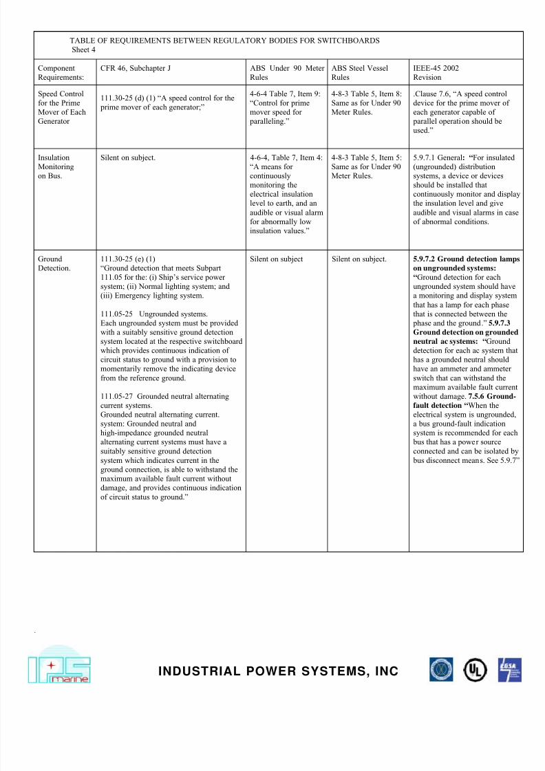
TABLE OF REQUIREMENTS BETWEEN REGULATORY BODIES FOR SWITCHBOARDS
Sheet 4
Component
Requirements:
CFR 46, Subchapter J ABS Under 90 Meter
Rules
ABS Steel Vessel
Rules
IEEE-45 2002
Revision
Speed Control
for the Prime
Mover of Each
Generator
111.30-25 (d) (1) “A speed control for the
prime mover of each generator;”
4-6-4 Table 7, Item 9:
“Control for prime
mover speed for
paralleling.”
4-8-3 Table 5, Item 8:
Same as for Under 90
Meter Rules.
.Clause 7.6, “A speed control
device for the prime mover of
each generator capable of
parallel operation should be
used.”
Insulation
Monitoring
on Bus.
Silent on subject. 4-6-4, Table 7, Item 4:
“A means for
continuously
monitoring the
electrical insulation
level to earth, and an
audible or visual alarm
for abnormally low
insulation values.”
4-8-3 Table 5, Item 5:
Same as for Under 90
Meter Rules.
5.9.7.1 General: “For insulate
(ungrounded) distribution
systems, a device or devices
should be installed that
continuously monitor and disp
the insulation level and give
audible and visual alarms in ca
of abnormal conditions.
Ground
Detection.
111.30-25 (e) (1)
“Ground detection that meets Subpart111.05 for the: (i) Ship's service power
system; (ii) Normal lighting system; and
(iii) Emergency lighting system.
111.05-25 Ungrounded systems.
Each ungrounded system must be provided
with a suitably sensitive ground detection
system located at the respective switchboard
which provides continuous indication of
circuit status to ground with a provision to
momentarily remove the indicating device
from the reference ground.
111.05-27 Grounded neutral alternating
current systems.Grounded neutral alternating current.
system: Grounded neutral and
high-impedance grounded neutral
alternating current systems must have a
suitably sensitive ground detection
system which indicates current in the
ground connection, is able to withstand the
maximum available fault current without
damage, and provides continuous indication
of circuit status to ground.”
Silent on subject Silent on subject. 5.9.7.2 Ground detection lam
on ungrounded systems:“Ground detection for each
ungrounded system should hav
a monitoring and display syste
that has a lamp for each phase
that is connected between the
phase and the ground.” 5.9.7.3
Ground detection on ground
neutral ac systems: “Ground
detection for each ac system th
has a grounded neutral should
have an ammeter and ammeter
switch that can withstand the
maximum available fault curre
without damage. 7.5.6 Ground
fault detection “When theelectrical system is ungrounde
a bus ground-fault indication
system is recommended for ea
bus that has a power source
connected and can be isolated
bus disconnect means. See 5.9
7/27/2019 Electrical Marine Rules Comparison
http://slidepdf.com/reader/full/electrical-marine-rules-comparison 6/11
.
INDUSTRIAL POWER SYSTEMS, INC
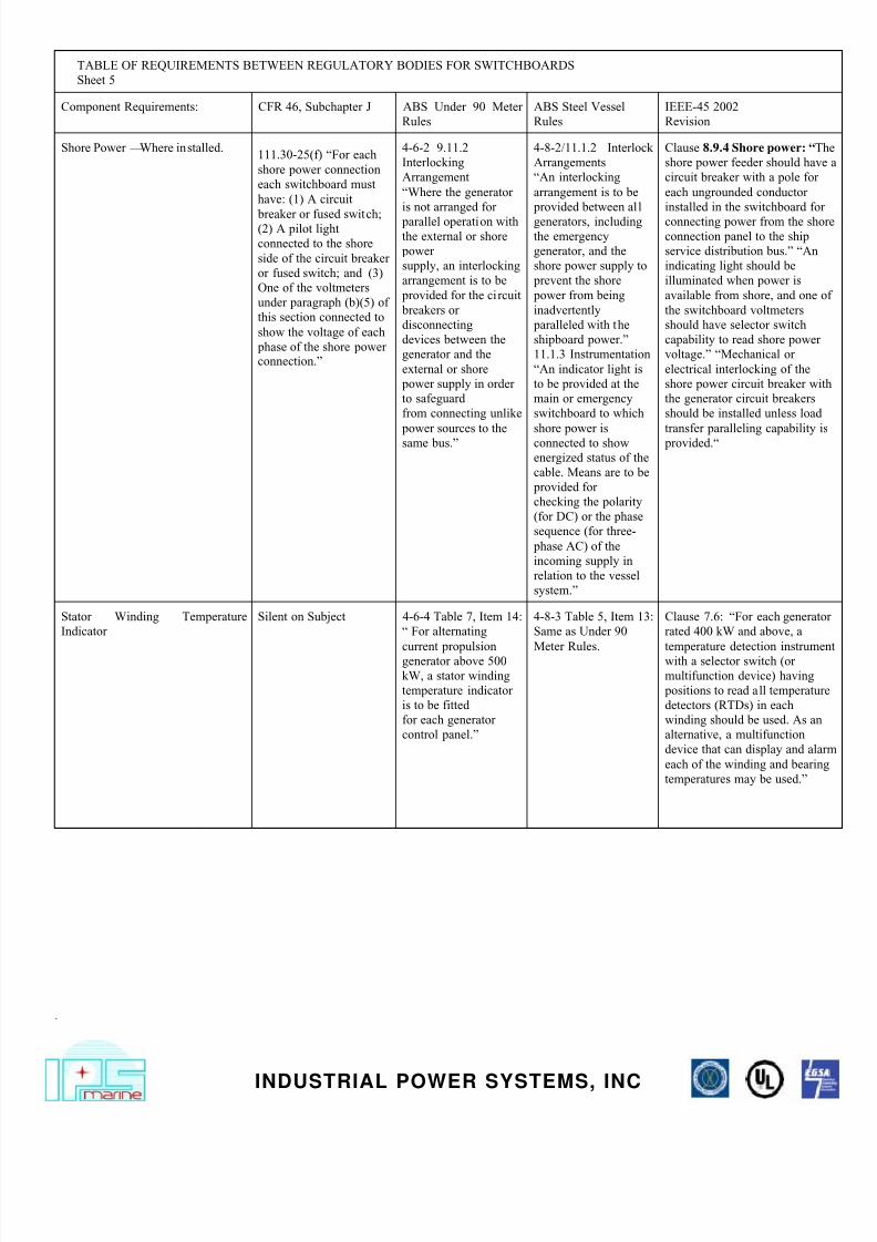
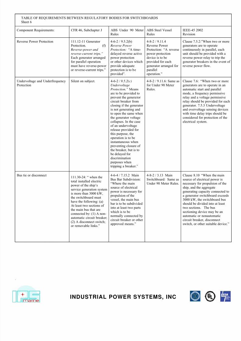
TABLE OF REQUIREMENTS BETWEEN REGULATORY BODIES FOR SWITCHBOARDS
Sheet 5
Component Requirements: CFR 46, Subchapter J ABS Under 90 Meter
Rules
ABS Steel Vessel
Rules
IEEE-45 2002
Revision
Shore Power –Where installed.111.30-25(f) “For each
shore power connection
each switchboard must
have: (1) A circuit
breaker or fused switch;(2) A pilot light
connected to the shore
side of the circuit breaker
or fused switch; and (3)
One of the voltmeters
under paragraph (b)(5) of
this section connected to
show the voltage of each
phase of the shore powerconnection.”
4-6-2 9.11.2
Interlocking
Arrangement
“Where the generator
is not arranged for
parallel operation withthe external or shore
power
supply, an interlocking
arrangement is to be
provided for the circuit
breakers or
disconnecting
devices between the
generator and the
external or shore
power supply in order
to safeguard
from connecting unlike
power sources to the
same bus.”
4-8-2/11.1.2 Interlock
Arrangements
“An interlocking
arrangement is to be
provided between all
generators, includingthe emergency
generator, and the
shore power supply to
prevent the shore
power from being
inadvertently
paralleled with the
shipboard power.”
11.1.3 Instrumentation
“An indicator light is
to be provided at the
main or emergency
switchboard to which
shore power is
connected to show
energized status of the
cable. Means are to be
provided for
checking the polarity
(for DC) or the phase
sequence (for three-
phase AC) of the
incoming supply in
relation to the vessel
system.”
Clause 8.9.4 Shore power: “T
shore power feeder should hav
circuit breaker with a pole for
each ungrounded conductor
installed in the switchboard fo
connecting power from the shoconnection panel to the ship
service distribution bus.” “An
indicating light should be
illuminated when power is
available from shore, and one
the switchboard voltmeters
should have selector switch
capability to read shore power
voltage.” “Mechanical or
electrical interlocking of the
shore power circuit breaker wi
the generator circuit breakers
should be installed unless load
transfer paralleling capability i
provided.“
Stator Winding Temperature
Indicator
Silent on Subject 4-6-4 Table 7, Item 14:
“ For alternating
current propulsiongenerator above 500
kW, a stator winding
temperature indicator
is to be fitted
for each generator
control panel.”
4-8-3 Table 5, Item 13:
Same as Under 90
Meter Rules.
Clause 7.6: “For each generat
rated 400 kW and above, a
temperature detection instrumewith a selector switch (or
multifunction device) having
positions to read all temperatur
detectors (RTDs) in each
winding should be used. As an
alternative, a multifunction
device that can display and ala
each of the winding and bearin
temperatures may be used.”
7/27/2019 Electrical Marine Rules Comparison
http://slidepdf.com/reader/full/electrical-marine-rules-comparison 7/11
.
INDUSTRIAL POWER SYSTEMS, INC
TABLE OF REQUIREMENTS BETWEEN REGULATORY BODIES FOR SWITCHBOARDS
Sheet 6
Component Requirements: CFR 46, Subchapter J ABS Under 90 Meter
Rules
ABS Steel Vessel
Rules
IEEE-45 2002
Revision
Reverse Power Protection 111.12-11 Generator
Protection. (f)
Reverse-power and
reverse-current trips.”
Each generator arranged
for parallel operation
must have reverse-power
or reverse-current trips.”
4-6-2 / 9.5.2(b)
Reverse Power
Protection: “A time-
delayed reverse active
power protection
or other devices which
provide adequate
protection is to be
provided”.
4-8-2 / 9.11.4
Reverse Power
Protection: “A reverse
power protection
device is to be
provided for each
generator arranged for
parallel
operation.”
Clause 7.5.2:”When two or mo
generators are to operate
continuously in parallel, each
unit should be provided with a
reverse power relay to trip the
generator breakers in the event
reverse power flow.
Undervoltage and Underfrequency
Protection
Silent on subject. 4-6-2 / 9.5.2(c)
Undervoltage
Protection.” Means
are to be provided to
prevent the generator
circuit breaker from
closing if the generator
is not generating and
to open the same when
the generator voltage
collapses. In the case
of an undervoltage
release provided for
this purpose, the
operation is to be
instantaneous when
preventing closure of
the breaker, but is to
be delayed for
discrimination
purposes when
tripping a breaker.”
4-8-2 / 9.11.6: Same as
for Under 90 Meter
Rules.
Clause 7.6: “When two or mo
generators are to operate in an
automatic start and parallel
mode, a frequency permissive
relay and a voltage permissive
relay should be provided for ea
generator. 7.5.3 Undervoltage
and overvoltage sensing devic
with time delay trips should be
considered for protection of th
electrical system.
Bus tie or disconnect111.30-24: “ when the
total installed electric
power of the ship's
service generation system
is more than 3000 kW,
the switchboard must
have the following: (a)
At least two sections of
the main bus that are
connected by: (1) A non-
automatic circuit breaker;
(2) A disconnect switch;
or removable links.”
4-6-4 / 7.15.2 Main
Bus Bar Subdivision:“Where the main
source of electrical
power is necessary for
propulsion of the
vessel, the main bus
bar is to be subdivided
into at least two parts
which is to be
normally connected by
circuit breaker or other
approved means.”
4-8-2 / 3.13 Main
Switchboard: Same asUnder 90 Meter Rules.
Clause 8.10 “When the main
source of electrical power isnecessary for propulsion of the
ship, and the aggregate
generating capacity connected
a generator switchboard excee
3000 kW, the switchboard bus
should be divided into at least
two sections. The bus
sectioning device may be an
automatic or nonautomatic
circuit breaker, disconnect
switch, or other suitable device
7/27/2019 Electrical Marine Rules Comparison
http://slidepdf.com/reader/full/electrical-marine-rules-comparison 8/11
.
INDUSTRIAL POWER SYSTEMS, INC
TABLE OF REQUIREMENTS BETWEEN REGULATORY BODIES FOR SWITCHBOARDS
Sheet 7
Component
Requirements:
CFR 46, Subchapter J ABS Under 90 Meter
Rules
ABS Steel Vessel
Rules
IEEE-45 2002
Revision
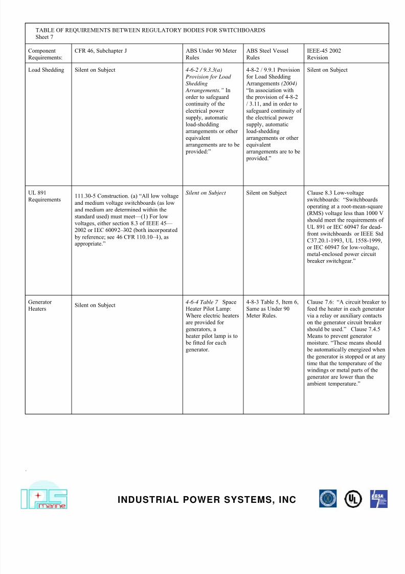
Load Shedding Silent on Subject 4-6-2 / 9.3.3(a)
Provision for Load
Shedding
Arrangements.” In
order to safeguard
continuity of the
electrical power
supply, automatic
load-shedding
arrangements or other
equivalent
arrangements are to be
provided:”
4-8-2 / 9.9.1 Provision
for Load Shedding
Arrangements (2004)
“In association with
the provision of 4-8-2
/ 3.11, and in order to
safeguard continuity of
the electrical power
supply, automatic
load-shedding
arrangements or other
equivalent
arrangements are to be
provided.”
Silent on Subject
UL 891
Requirements
111.30-5 Construction. (a) “All low voltage
and medium voltage switchboards (as lowand medium are determined within the
standard used) must meet—(1) For low
voltages, either section 8.3 of IEEE 45–
2002 or IEC 60092–302 (both incorporated
by reference; see 46 CFR 110.10–1), asappropriate.”
Silent on Subject Silent on Subject Clause 8.3 Low-voltage
switchboards: “Switchboardsoperating at a root-mean-squar
(RMS) voltage less than 1000
should meet the requirements
UL 891 or IEC 60947 for dead
front switchboards or IEEE S
C37.20.1-1993, UL 1558-1999
or IEC 60947 for low-voltage,
metal-enclosed power circuit
breaker switchgear.”
GeneratorHeaters
Silent on Subject 4-6-4 Table 7 SpaceHeater Pilot Lamp:
Where electric heaters
are provided for
generators, a
heater pilot lamp is to
be fitted for each
generator.
4-8-3 Table 5, Item 6,Same as Under 90
Meter Rules.
Clause 7.6: “A circuit breakerfeed the heater in each generat
via a relay or auxiliary contact
on the generator circuit breake
should be used.” Clause 7.4.5
Means to prevent generator
moisture. “These means should
be automatically energized wh
the generator is stopped or at a
time that the temperature of th
windings or metal parts of the
generator are lower than the
ambient temperature.”
7/27/2019 Electrical Marine Rules Comparison
http://slidepdf.com/reader/full/electrical-marine-rules-comparison 9/11
.
INDUSTRIAL POWER SYSTEMS, INC
TABLE OF REQUIREMENTS BETWEEN REGULATORY BODIES FOR SWITCHBOARDS
Sheet 8
Component Requirements: CFR 46, Subchapter J ABS Under 90 Meter
Rules
ABS Steel Vessel
Rules
IEEE-45 2002
Revision
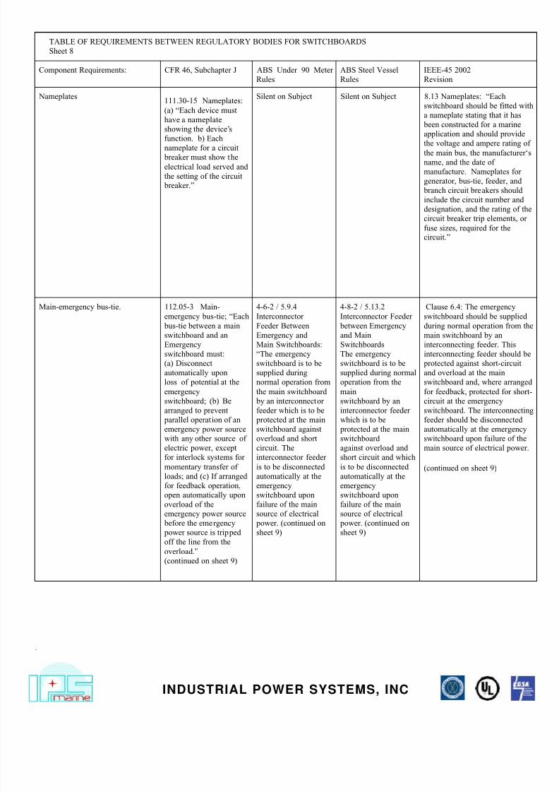
Nameplates111.30-15 Nameplates:
(a) “Each device must
have a nameplate
showing the device's
function. b) Eachnameplate for a circuit
breaker must show the
electrical load served and
the setting of the circuit
breaker.”
Silent on Subject Silent on Subject 8.13 Nameplates: “Each
switchboard should be fitted w
a nameplate stating that it has
been constructed for a marine
application and should provide
the voltage and ampere rating
the main bus, the manufacturer
name, and the date of
manufacture. Nameplates for
generator, bus-tie, feeder, and
branch circuit breakers should
include the circuit number and
designation, and the rating of t
circuit breaker trip elements, o
fuse sizes, required for thecircuit.”
Main-emergency bus-tie. 112.05-3 Main-
emergency bus-tie; “Each
bus-tie between a main
switchboard and an
Emergency
switchboard must:
(a) Disconnect
automatically upon
loss of potential at the
emergency
switchboard; (b) Be
arranged to prevent
parallel operation of an
emergency power source
with any other source of
electric power, except
for interlock systems for
momentary transfer of
loads; and (c) If arranged
for feedback operation,
open automatically upon
overload of the
emergency power source
before the emergency
power source is tripped
off the line from the
overload.”(continued on sheet 9)
4-6-2 / 5.9.4
Interconnector
Feeder Between
Emergency and
Main Switchboards:
“The emergency
switchboard is to be
supplied during
normal operation from
the main switchboard
by an interconnector
feeder which is to be
protected at the main
switchboard against
overload and short
circuit. The
interconnector feeder
is to be disconnected
automatically at the
emergency
switchboard upon
failure of the main
source of electrical
power. (continued on
sheet 9)
4-8-2 / 5.13.2
Interconnector Feeder
between Emergency
and Main
Switchboards
The emergency
switchboard is to be
supplied during normal
operation from the
main
switchboard by an
interconnector feeder
which is to be
protected at the main
switchboard
against overload and
short circuit and which
is to be disconnected
automatically at the
emergency
switchboard upon
failure of the main
source of electrical
power. (continued on
sheet 9)
Clause 6.4: The emergency
switchboard should be supplie
during normal operation from
main switchboard by an
interconnecting feeder. This
interconnecting feeder should
protected against short-circuit
and overload at the main
switchboard and, where arrang
for feedback, protected for sho
circuit at the emergency
switchboard. The interconnect
feeder should be disconnected
automatically at the emergency
switchboard upon failure of th
main source of electrical powe
(continued on sheet 9)
7/27/2019 Electrical Marine Rules Comparison
http://slidepdf.com/reader/full/electrical-marine-rules-comparison 10/11
.
INDUSTRIAL POWER SYSTEMS, INC
TABLE OF REQUIREMENTS BETWEEN REGULATORY BODIES FOR SWITCHBOARDS
Sheet 9
Component Requirements: CFR 46, Subchapter J ABS Under 90 Meter
Rules
ABS Steel Vessel
Rules
IEEE-45 2002
Revision
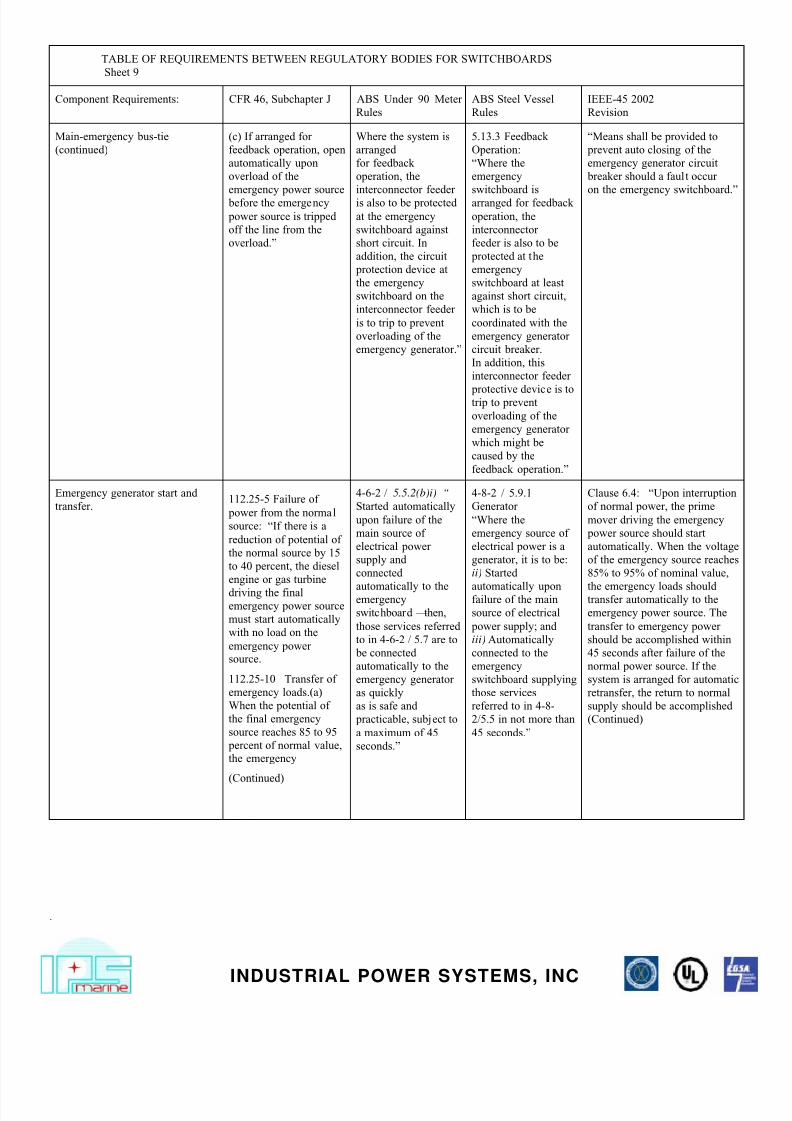
Main-emergency bus-tie
(continued)
(c) If arranged for
feedback operation, open
automatically upon
overload of the
emergency power source
before the emergency
power source is tripped
off the line from the
overload.”
Where the system is
arranged
for feedback
operation, the
interconnector feeder
is also to be protected
at the emergency
switchboard against
short circuit. In
addition, the circuit
protection device at
the emergency
switchboard on the
interconnector feeder
is to trip to prevent
overloading of the
emergency generator.”
5.13.3 Feedback
Operation:
“Where the
emergency
switchboard is
arranged for feedback
operation, the
interconnector
feeder is also to be
protected at the
emergency
switchboard at least
against short circuit,
which is to be
coordinated with the
emergency generator
circuit breaker.
In addition, this
interconnector feeder
protective device is totrip to prevent
overloading of the
emergency generator
which might be
caused by the
feedback operation.”
“Means shall be provided to
prevent auto closing of the
emergency generator circuit
breaker should a fault occur
on the emergency switchboard.”
Emergency generator start and
transfer.112.25-5 Failure of
power from the normal
source: “If there is a
reduction of potential of
the normal source by 15
to 40 percent, the diesel
engine or gas turbine
driving the finalemergency power source
must start automatically
with no load on the
emergency powersource.
112.25-10 Transfer of
emergency loads.(a)
When the potential of
the final emergency
source reaches 85 to 95
percent of normal value,
the emergency
(Continued)
4-6-2 / 5.5.2(b)i) “
Started automatically
upon failure of the
main source of
electrical power
supply and
connected
automatically to theemergency
switchboard –then,
those services referred
to in 4-6-2 / 5.7 are to
be connected
automatically to the
emergency generator
as quickly
as is safe and
practicable, subject to
a maximum of 45
seconds.”
4-8-2 / 5.9.1
Generator
“Where the
emergency source of
electrical power is a
generator, it is to be:
ii) Started
automatically uponfailure of the main
source of electrical
power supply; and
iii) Automatically
connected to the
emergency
switchboard supplying
those services
referred to in 4-8-
2/5.5 in not more than
45 seconds.”
Clause 6.4: “Upon interruption
of normal power, the prime
mover driving the emergency
power source should start
automatically. When the voltage
of the emergency source reaches
85% to 95% of nominal value,
the emergency loads shouldtransfer automatically to the
emergency power source. The
transfer to emergency power
should be accomplished within
45 seconds after failure of the
normal power source. If the
system is arranged for automatic
retransfer, the return to normal
supply should be accomplished
(Continued)
7/27/2019 Electrical Marine Rules Comparison
http://slidepdf.com/reader/full/electrical-marine-rules-comparison 11/11
.
INDUSTRIAL POWER SYSTEMS INC
TABLE OF REQUIREMENTS BETWEEN REGULATORY BODIES FOR SWITCHBOARDS
Sheet 10
Component Requirements: CFR 46, Subchapter J ABS Under 90 Meter
Rules
ABS Steel Vessel
Rules
IEEE-45 2002
Revision
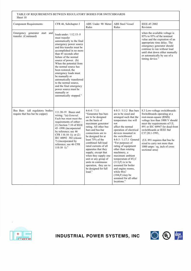
Emergency generator start and
transfer. (Continued)loads under § 112.15–5
must transfer
automatically to the final
emergency power source
and this transfer must beaccomplished in no more
than 45 seconds after
failure of the normal
source of power. (b)
When the potential from
the normal source has
been restored, the
emergency loads must
be manually or
automatically transferred
to the normal source,
and the final emergency
power source must be
manually or
automatically stopped.”
when the available voltage is
85% to 95% of the nominal
value and the expiration of an
appropriate time delay. The
emergency generator should
continue to run without load
until shut down either manually
or automatically by use of a
timing device.”
Bus Bars (all regulatory bodies
require that bus bar be copper)111.30-19 Buses and
wiring. “(a) General.
Each bus must meet the
requirements of either—
(1) Section 7.10 of IEEE
45–1998 (incorporated
by reference; see 46
CFR 110.10–1); or (2)
IEC 60092–302 (clause
7) (incorporated byreference; see 46 CFR
110.10–1).”
4-6-4 / 7.11
“Generator bus bars
are to be designed
on the basis of
maximum generator
rating. All other bus
bars and bus-bar
connections are to
be designed for at
least 75% of the
combined full-loadrated currents of all
apparatus that they
supply, except that
when they supply one
unit or any group of
units in continuous
operation, they are to
be designed for full
load.”
4-8-3 / 5.3.2 Bus bars
are to be sized and
arranged such that the
temperature rise will
not
affect the normal
operation of electrical
devices mounted in
the switchboard.
4-8-3 / 1.17.1 General
“For purposes ofrating of equipment
other than rotating
machinery, a
maximum ambient
temperature of 45°C
(113°F) is to be
assumed for boiler
and engine rooms,
while 40°C
(104°F) may be
assumed for all other
locations.”
8.3 Low-voltage switchboards:
Switchboards operating at a
root-mean-square (RMS)
voltage less than 1000 V should
meet the requirements of UL
891 or IEC 60947 for dead-front
switchboards or IEEE Std
C37.20.1-1993,
(UL 891 requires that bus be
sized to carry not more than1000 amps / sq. inch of cross
sectional area)