Embed Size (px)
Citation preview

8/20/2019 electrical guide 5.pdf
http://slidepdf.com/reader/full/electrical-guide-5pdf 1/343
8/20/2019 electrical guide 5.pdf
http://slidepdf.com/reader/full/electrical-guide-5pdf 2/343

8/20/2019 electrical guide 5.pdf
http://slidepdf.com/reader/full/electrical-guide-5pdf 3/343
^
k-^oH
Presented
to the
LIBRARY
of
the
UNIVERSITY OF
TORONTO
by
Reverend Michael
Sheehan

8/20/2019 electrical guide 5.pdf
http://slidepdf.com/reader/full/electrical-guide-5pdf 4/343
8/20/2019 electrical guide 5.pdf
http://slidepdf.com/reader/full/electrical-guide-5pdf 5/343
THOUGHT
IS
IN
THE QUESTION THE
INFORMATION
IS
IN
THE
ANSWER
riAWKlNs
ELtaRML
mh
^
'
^
QUESTIONS
' ^
^NSWERg
ILLUSTRATIONS
A
PROGRESSIVE
COURSE OF
STUDY
FOR ENGINEERS,
ELECTRICIANS,
STUDENTS
AND
THOSE
DESIRING
TO
ACQUIRE
A
WORKING KNOWLEDGE
OF
m
its
Mic/iTiais
A
PRACTICAL
TREATISE
HAWKINS^g^ND
STAFF
THEO.
AUDEL
&
C0^^72
FIFTH
AVE. NEW
YORK.
8/20/2019 electrical guide 5.pdf
http://slidepdf.com/reader/full/electrical-guide-5pdf 6/343
Impression
1922
COPYRIGHTED,
1917,
BY
THEO.
AUDEL
&
CO.,
New York
DEC
12
X
iS&5
Printed in the
United
States
8/20/2019 electrical guide 5.pdf
http://slidepdf.com/reader/full/electrical-guide-5pdf 7/343
TABLE OF
CONTENTS;
GUIDE
NO.
5
TABLE
OF
CONTENTS
GUIDE
NO. 5.
ALTERNATING
CURRENT
MOTORS
1,267
to
1,376
Classification—synchronous motors— essential parts
—
synchronous
motor principles:
condition
for
starting
; effect-
ive
pressure;
dead
centers;
speed;
limit of
lag;
effect of
load changes— effect
of
altering the field
strength—
disad-
vantages of synchronous
motors;
advantages
—
the
**V
curve
—
adaptation
—
efficiency
—hunting
of
synchron-
ous
motors;
mechanical
analogy—
use
as
condenser-
surging- characteristics
of
synchronous
motors:
starting;
running; stopping;
effect
upon
circuit;
power
factor;
auxiliary
apparatus
;
adaptation
—
induction
(asyn-
chronous) motors
—
essential
parts
—
types
oscillating
magnetic
field
—
rotating magnetic
^e/rf—
operation
of
single
phase
motor; why not self
starting; provision
for
starting
—
operation
of
polyphase
induction motor;
why
called
asyn-
chronous—speed; classification
according
to
speed—
the
terms primary
and
secondary—why
polyphase induction
motors
are
explained before
single phase—polyphase
in-
duction
motors
—
features
—
essential
parts
principles
—
production
of
rotating
field
—Tesla's
rotating
field
—method
of
obtaining
resultant flux
of Tesla's
field-
A
r
ago'
s
rota-
tions;
explanation—
Faraday's
experiment— production
of
two
phase rotating field;
resultant
poles
—
six and
eight
pole
two phase
rotating fields— physical
conception
of
two
phase
rotating
field—
pvodnction
of three phase
rotating
field;
with
ring
v/inding—
physical
conception
of
three
phase
rotating
field-
three phase
six pole winding
—
slip—
co^/?er
cylinder illustrating
principle
of
operation
of
induction motor
—calculation
of slip—
table of
synchronous
speeds—
varia-
tion
of
slip;
why
so
small;
variation
with
load;
table of
variation—
sector
method of measuring
s^p—
evolution
of
8/20/2019 electrical guide 5.pdf
http://slidepdf.com/reader/full/electrical-guide-5pdf 8/343
TABLE
OF CONTENTS; GUIDE
NO.
5
ALTERNATING
CURRENT
MOTOK^—
Continued.
the
squirrel
cage armature;
construction
—
the field
magnets
;
parts; constructiqm— field windings
for
induction mo-
tors—calculation
for revolutions
of
rotating
field;
objection
to
high
speed
of
field—
difficulty
with
low
frequency
currents
—general
character
of field winding—
formation
of
poles—
grouping
of co\\s— starting
of
induction
motors:
external
resistance,
auto-transformer,
internal resistance
methods
—
internal
resistance induction
motors
;
adaptation
—
how
resistance is
cut out—why not
desirable
for
large
sizes—
external resistance or
slip
ring
motors—
operation
—
armature connections—
single
phase induction
motors
—
service suitable for—disadvantage—
parts—
why
not
self-
starting—
how
started—phase
splitting;
production
of
rotating
field
from
oscillating
field—
methods—
starting
coils—
shading coils
—
character
of
the
starting
torque—
modification of armature
for
starting
with
heavy
load
—
clutch type
of
single phase induction
motor; its action in
starting
—
commutator
motors—
classification
—
ac/z'ow
of
closed
coil
rotating in
alternating
field—
the
transformer
pressure
—
generated
pressure
—
self-induction
pressure
local armature currents; reason for
sparking;
how reduced
—high resistance connectors
—
effect
of low
power
factor—
effect
of
frequency—
series
motor—
features—
adaptation—
neutralized
series motor
— conductive
method—
inductive
method shunt motors —
repulsion motors
—
difficulty
with early
motors—
means employed
to
stop sparking
—
essentials
of single repulsion motors—
the
term repul-
sion induction motor
—
compensated
repulsion
motor
—
power
factor
of induction
motors—
its
importance
—
false
ideas in regard to
power
factor—
speed
and
torque
of motors.
TRANSFORMERS
1,377
to
1,456
Their
use—essential parts— basic
principles
—
the
primary
winding—
the secondary winding— magnetic leakage
—
the
induced
voltage
—
no load current
—
magnetizing current
—
action
of
transformer with
load—
classification—
step
up
transformers
—
use
—
construction
—
copper
economy
?tep down transformers—
use—
construction—
core
trans-
formers—construction—advantages—shell
transform-
ers—comparison of core
and
shell
types— choice
—
com-
bined core and shell
transformers—
economy
of con-
struction—single
and
polyphase
transformers— features
of
each
type
—
choice
of
types for
polyphase
currents
—
operation
of
three
phase
transformerwith
one phase
damaged
8/20/2019 electrical guide 5.pdf
http://slidepdf.com/reader/full/electrical-guide-5pdf 9/343
TABLE OF
CONTENTS;
GUIDE
NO.
5
TRANSFORMERS—
Con/^«we(?.
—
transformer
losses
—
hysteresis
—
what
governs
the
loss
—
how
reduced
—
eddy
currents
—
lamination
—
thick-
ness
of
laminse
—
importance
of iron
losses
—
how
to reduce
iron
losses
—
copper
losses—
how
caused—
effect
on
power
factor—
effect of resistance
—
cooling
of
transformers
—
cooHng
mediums
employed—
heating
of transformers
—
objection
to
heating—
dry
ti^nsformers—
air
cooled
transformers—
natural
draught
type—
forced draught
or
air
blast
type—
construction
of coils
for air cooling
—
requirements with respect
to
air supply—
quantity
of
air
used—
oil cooled
transformers—
circulation
of
the oil
—
action
of
the
oil—
objection
to
oil—
kind
of
oil
used—
oil
requirements—
moisture
in
oil—
water
cooled transform-
ers
—
internal
coil
type
—
external
coil
type
thermo-cir-
culation—quantity
of
circulating
water
required
—
trans-
former insulation—
the major
and
minor
insula-
tion—mica—outdoor
transformers for irrigation
service
—
oil
insulated transformers—efficiency
of transformers—
effi-
ciency curve—
all
day
efficiency
of
transformers
—
trans-
former fuse
blocks— auto-transformers
—
constant
current
transformers
for series
arc
lighting; elementary
dia-
gram
illustrating principles—regulation— transformer con-
nections—single phase connections—combining transform-
ers—
precautions—
operating secondaries in parallel— con-
nections
for
different
voltages—
precautions—
two
phase
connections
—
three
phase connections : delta,
star,
delta-
star, star-delta— comparison
of star
and delta
connections
—
three
phase transformers
—
comparison
of
air
blast,
water
cooled,
and
oil cooled transformers—
standard transformer
connections
—
how
to
test
transformers
—
transformer
operation
with grounded secondary—
transformer
capacity
for
motors
—
transformer
connections
for
motors—
arc
lamp
transformer
—
transformer
installed
on
pole—
static
booster
or
regulating
transformer.
CONVERTERS
-
-
1,457
to
1,494
Where
used—
kinds of
converter—
A. I.
E.
E.
classification
—rotary
converters
—operation
—
speed
—
principles
—
rela-
tion between
inout
and output
pressures
—
single
and poly-
phase
types
—
advantage of
polyphase
converters—armature
connections
of polyphase converter—
pressure
relation
—
voltage
variation—
advantage
of unity
power
factor
—
effect
of
field too
strong—compounding
of
rotary
converters
—
8/20/2019 electrical guide 5.pdf
http://slidepdf.com/reader/full/electrical-guide-5pdf 10/343
TABLE OF
CONTENTS:
GUIDE
NO. 5
CONVERTERS—
Continued.
ratio
of
conversion—
voltage regulation—
split
pole
method—
regulating
pole method— best
location
of
regulat-
ing poles—
reactance
method—
multi-
tap
transformer
method—
synchronous
booster
method
—
winding
con-
nections—field
connections—
adaptation—
motor generator
sets—
classification— standard
practice—
behavior of rotary
when
hunting; comparison with motor
generator
sets-
racing—
frequency changing sets—
parallel
operation
of
frequency
changers
—
cascade
converter—
speed—ac-
tion inmotorarmature
winding
—
advantages—
how
started
—
comparison
of
cascade
converter
with
synchronous
converter.
RECTIFIERS
1,495
to
1,530
Classification—
mechanical
rectifiers
—
essential
features
—
construction
—
application
—
electrolytic
rectifiers
—
prin-
ciples
of
operation
—
Mohawk
rectifier
— the
term valve
—
metals
for
electrodes— electrolyte —Nodon valve—Audion
valve—Buttner
valve
—
Churcher
valve-
De
Faria
valve
—
Fleming oscillation
valve
—
Grisson valve—Pawlowski valve
—Giles electric
valve
—
Buttner
valve
mercury
vapor
rectifiers—
principles
—
the terms
arc
and
vapor
—
three
phase
mercury
vapor rectifier
—
construction— auxiliary
apparatus
—
series
mercury
arc rectifier
—
dissipation
of heat
from bulb—replacement
of bulb—
advantages of
rectifier
precautions
in installing electromagnetic
rectifiers—
construction
and
operation.
ALTERNATING
CURRENT
SYSTEMS
1,531
to
1,583
Advantages
of
the alternating current
—
classification
of
systems
—
vector
summation
;
examples
—
forms
of
cir-
cuit:
series,
parallel,
parallel series,
series
parallel
—
transformer
systems:
individual
transformers;
trans-
formation
at
distribution
centers
—
single
phase
system;
two
wire
transmission
and
three
wire
distribution;
ob-
jections
to
single
phase
systems; advantages
—
mono-
cyclic
system
—
two
phase
systems:
adaptation;
ordi-
nary
voltages
used;
two
phase
three wire
system; two
phase
five
wire
system
—
three
phase systems:
six
wire;
four
wire;
three
wire;
connections:
star, delta,
star
delta,
delta
star;
evolution
of three
wire system; pressure
and
current
8/20/2019 electrical guide 5.pdf
http://slidepdf.com/reader/full/electrical-guide-5pdf 11/343
TABLE
OF
CONTENTS;
GUIDE
NO.
5
ALTERNATING
CURRENT
SYSTEM—
Cow/mwe^.
relations;
connection
of transformers;
open
delta
connec-
tion
—
change
of
frequency
—
Schaghticoke-Schenectady
transmission
line
—
transformation of
phases
: three
to
one,
three
to
two,
two
to
six, and
three
to six
phase
—
Scott
connection
for
transforming
from
three
to two
phase
—
three
to
two phase
with
three
star
connected
transformers
—
economy
of
a. c.
systems
—
relative weights
of
cop-
per
required
for
polyphase systems
—
aermotor
towers
of
Southern
Power
Co.
—
choice of voltage
—
usual
trans-
mission
voltages
—
diagram of
three
phase distribu-
tion
—
mixed
current systems; usual
d. c. pressure
on
traction
lines;
use of
mixed
systems.
8/20/2019 electrical guide 5.pdf
http://slidepdf.com/reader/full/electrical-guide-5pdf 12/343
8/20/2019 electrical guide 5.pdf
http://slidepdf.com/reader/full/electrical-guide-5pdf 13/343
ALTERNATING
CURRENT MOTORS 1,267
CHAPTER
LI
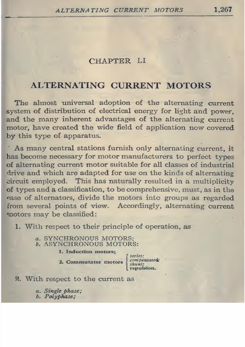
ALTERNATING
CURRENT MOTORS
The
almost
universal adoption
of
the
alternating
current
system
of
distribution of
electrical
energy
for
light
and power,
and
the
many
inherent
advantages
of
the
alternating
current
motor,
have
created
the
wide field
of application
now
covered
by
this type
of
apparatus.
As
many
central
stations
furnish
only
alternating
current,
it
has
become
necessary
for
motor
manufacturers
to
perfect
types
of
alternating
current motor suitable
for
all
classes
of
industrial
drive
and
which are adapted
for
use on
the
kinds of
alternating
circuit
employed.
This
has naturally
resulted
in
a
multiplicity
of
types and
a
classification, to
be
comprehensive,
must,
as in
the
<jase
of
alternators,
divide the
motors
into groups
as
regarded
from
several
points
of
view.
Accordingly,
alternating
current
motors
may
be
classified:
1.
With
respect
to
their principle of operation,
as
a.
SYNCHRONOUS MOTORS;
b. ASYNCHRONOUS
MOTORS:
1.
Induction
motors;
(series;
repulsion.
9,.
With
respect
to the current as
a. Single
phase;
b.
Polyphase;
8/20/2019 electrical guide 5.pdf
http://slidepdf.com/reader/full/electrical-guide-5pdf 14/343
1.268
HAWKINS
ELECTRICITY
Bl/
>
EXTERNAL
CIRCUIT
ALTERNATOR
SYNCHRONOUS
MOTOR
-^ORQ^-
EXTERNAL
CIRCUIT
ALTERNATOR
SYNCHRONOUS
MOTOR
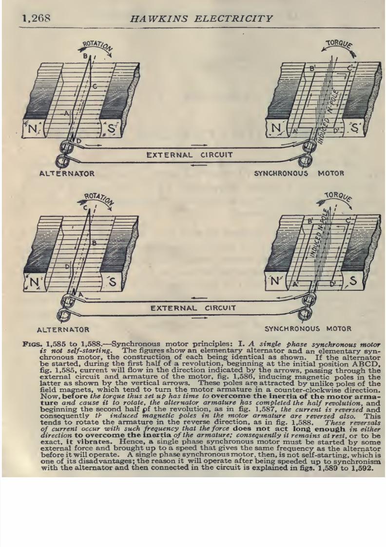
Figs.
1,585
to
1,588.
—
Synchronous
motor principles:
I.
A
single
phase
synchronous
motor
is
not self-starting.
The figures show
an
elementary
alternator
and
an elementary syn-
chronous
motor, the
construction
of
each
being identical
as
shown.
If
the alternator
be
started,
during
the first half of a revolution, beginning
at
the
initial
position ABCD,
fig. 1,585,
current
will
flow
in the
direction
indicated
by
the
arrows,
passing
through
the
external
circuit
and
armature
of
the
motor, fig.
1,586, inducing
magnetic
poles
in
the
latter
as
shown
by
the
vertical
arrows.
These poles are
attracted
by
unlike
poles of the
field
magnets,
which
tend to
turn
the
motor armature
in
a
counter-clockwise
direction.
Now,
before
the torque
thus
set
up
has
time
to
overcome
the
inertia
of
the
motor arma-
ture
and cause it
to
rotate,
the
alternator armature has
completed
the
half revolution,
and
beginning
the second
half pf
the revolution, as in
fig.
1,587, the
current
is
reversed and
consequently
th
induced magnetic
poles
in
the
motor armature
are
reversed
also.
This
tends
to
rotate
the armature in the
reverse
direction,
as
in fig.
1,588. These reversals
of
current
occur
with
such
frequency
that
the
force
does
not
act
long
enough
in
either
direction
to
overcome the
inertia
of
the
armature;
consequently
it
remains
at
rest,
or to be
exact,
it
vibrates.
Hence,
a
single
phase synchronous
motor
must
be
started
by
some
external
force and
brought
up
to a
speed that gives
the
same
frequency
as
the
alternator
before it
will
operate.
A
single phase
synchronous motor,
then,
is
not
self
-starting, which
is
one
of its
disadvantages;
the
reason
it will
operate
after
being
speeded
up
to synchronism
with
the
alternator and
then connected in
the
circuit is
explained
in figs.
1,589
to
1,592.
8/20/2019 electrical guide 5.pdf
http://slidepdf.com/reader/full/electrical-guide-5pdf 15/343
ALTERNArriNG
CURRENT MOTORS
1,269
3.
With
respect
to
speed,
as
a.
Constant
speed;
b.
Variable
speed.
4.
With
respect
to structural
features,
as
»
a.
Enclosed;
b.
Semi-enclosed;
c.
Open;
d.
Pipe ventilated;
e.
Back
geared;
/,
Skeleton
frame;
g.
Riveted frame;
h.
Ventilated;
etc.
Of
the
above
divisions
and
sub-divisions
some
are
self
-defining
and
need
little or no explanation;
the others,
however,
will
be
considered
in
detail,
with
explanations
of the
principles
of
opera-
tion and
construction.
Synchronous Motors.
—
The
term
synchronous
means
in unison,
that
is,
in
step. A
so called
synchronous
motor,
then,
as generally defined,
is one
which
rotates
in unison
or
in
step
with
the
phase
of
the alternating
current
which
operates it.
Strictly
speaking,
however,
it
should he
noted
that this
condition
of
operation
is
only
approximately
realized
as
will be
later
shown.
Any
single
or
polyphase
alternator
will
operate
as
a syn-
chronous motor when
supplied
with
current at
the
same
pressure
and frequency as it
produces
as a
generator,
the
essential
con-
dition, in
the
case
of
a
single
phase
machine,
being that
it
be
speeded
up
to
so called
synchronism
before
being
put in
the
circuit.
In
construction,
synchronous
motors are
almost
identical
with
the
corresponding alternator,
and consist
essentially
of
two
t^lements
1. An
armature,
2. A field.
8/20/2019 electrical guide 5.pdf
http://slidepdf.com/reader/full/electrical-guide-5pdf 16/343
1,270
HAWKINS
ELECTRICITY
EXTERNAL
CIRCUIT
ALTERNATOR
SYNCHRONOUS MOTOR
EXTERNAL, CIRCUIT
ALTERNATOR
SYNCHRONOUS
MOTOR
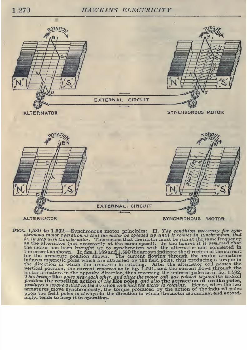
Pigs.
1,589
to
1,592.
—
Synchronous
motor
principles:
II. The
condition
necessary
for
syn-'
chronous
motor
operation
is that the
motor be
speeded
up
until
it
rotates
in
synchronism,
that
is,
in
step
with
the
alternator.
This means
that
the motor
must
be
run at the
same
frequency
as the
alternator
(not
necessarily
at
the
same
speed). In
the
figures
it
is
assumed
that
the
motor
has
been
brought
up
to
synchronism
with
the
alternator
and
connected in
the
circuit
as
shown.
In fi^s.
1
,689
and
1
,590
the arrows
indicate
the
direction
of
the
current
tor
the
armature
position
shown.
The
current
flowing
through
the
motor
armature
induces
magnetic
poles
which are attracted
by
the
field
poles,
thus
producing
a
torque
in
the
direction
in
which
the armature is
rotating.
After the
alternator
coil
passes
the
vertical
position,
the
current reverses as
in
fig. 1,591,
and
the
current
flows
through
the
motor
armature
in
the
opposite direction,
thus
reversing
the
induced
poles
as
in
fig.
1,592.
This
brings
like
poles
near each
other,
and since
the motor coil
has
rotated
beyond
the
vertical
position
the
repelling
action
of
the
like
poles,
and also the
attraction
of
unlike
poles.
Produces
a
torque
acting
in
the
direction in
which
the
motor
is
rotating.
Hence,
when
the two
armatures
move
synchronously,
the torque
produced
by
the
action of
the
induced
poles
upon
the
field
poles is
always
in the
direction
in
which
the
motor
is running,
and
accord-
ingly,
tends
to keep
it
in
operation.
8/20/2019 electrical guide 5.pdf
http://slidepdf.com/reader/full/electrical-guide-5pdf 17/343
ALTERNATING
CURRENT
MOTORS
1,271
either
of
which may revolve.
The
field
is separately
excited
with
direct
current.
The
principles
upon
which
such
motors
operate
may
be
ex-
plained
by
considering
the
action
of
two
elementary
alternators
NO
PHASE DIFFERENCE
BETWEEN
A.B.C.D
AND A',B\C',D'
IDEAL CASE.
NOT
POSSIBLE
IN
ACTUAL
MACHINES.
EXTERNAL
CIRCUIT
ALTERNATOR
SYNCHRONOUS
MOTOR
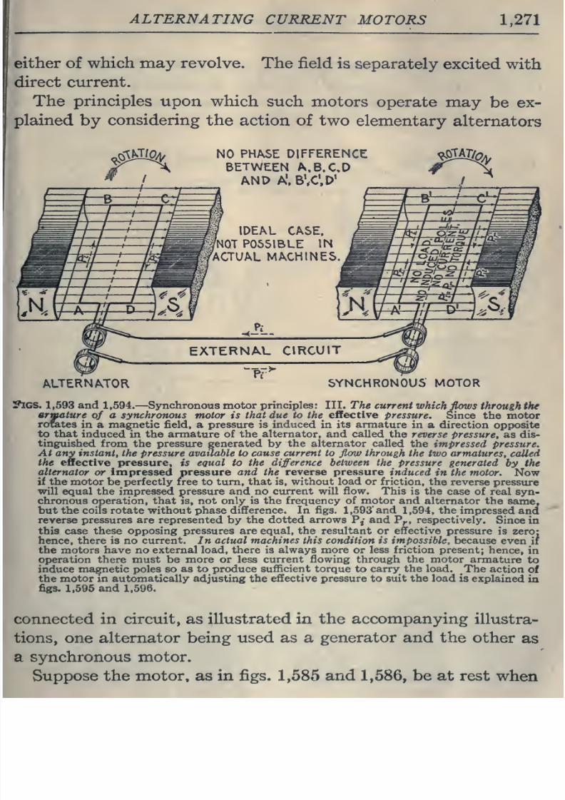
VlGS.
1,593
and 1,594.
—
Synchronous
motor principles:
III.
The
current
which
flows
through
the
armature
of
a synchronous
motor
is
that
due
to the
effective
pressure.
Since
the motor
rorates
in
a
magnetic
field,
a
pressure is
induced
in
its armature
in
a
direction
opposite
to that
induced
in the armature of the
alternator,
and
called
the
reverse
pressure, as dis-
tinguished
from
the
pressure
generated
by the
alternator
called
the
impressed
pressure.
At
any
instant,
the
pressure available to
cause
current
to
flow
through
the two
armatures,
called
the effective
pressure,
is
equal
to the
difference
between the
Pressure
generated
by
the
alternator
or impressed pressure
and
the
reverse pressure
induced
in
the
motor.
Now
if the
motor
be
perfectly
n-ee to
turn, that
is, without
load or
friction,
the
reverse
pressure
will
equal
the
impressed
pressure
and
no
current
will
flow.
This
is
the
case of
real syn-
chronous operation, that is,
not
only is
the
frequency of motor and
alternator the
same,
but
the
coils
rotate
without phase difference. In
figs.
1,593'
and
1,594,
the
impressed
and
reverse
pressures are represented
by
the
dotted arrows
P,- and
P^,
respectively.
Since
in
this
case
these
opposing
pressures are equal,
the
resultant or effective pressure
is zero:
hence,
there is
no
current.
In
actual
machines
this condition is
impossible,
because
even
if
the motors have no
external
load,
there
is
always
more
or
less friction present;
hence,
in
oi>eration
there must be
more or less current flowing through
the
motor
armature
to
induce magnetic poles so
as to produce
sufficient
torque to
carry
the
load. The
action
of
the
motor
in
automatically
adjusting the
effective
pressure
to suit the
load
is
explained
in
figs.
1,595
and
1,596.
connected
in
circuit,
as
illustrated
in the
accompanying
illustra-
tions, one
alternator being
used as a
generator and
the
other
as
a
synchronous
motor.
Suppose
the
motor,
as
in figs.
1,585
and
1,586,
be
at
rest
when
8/20/2019 electrical guide 5.pdf
http://slidepdf.com/reader/full/electrical-guide-5pdf 18/343
1,272
HAWKINS
ELECTRICITY
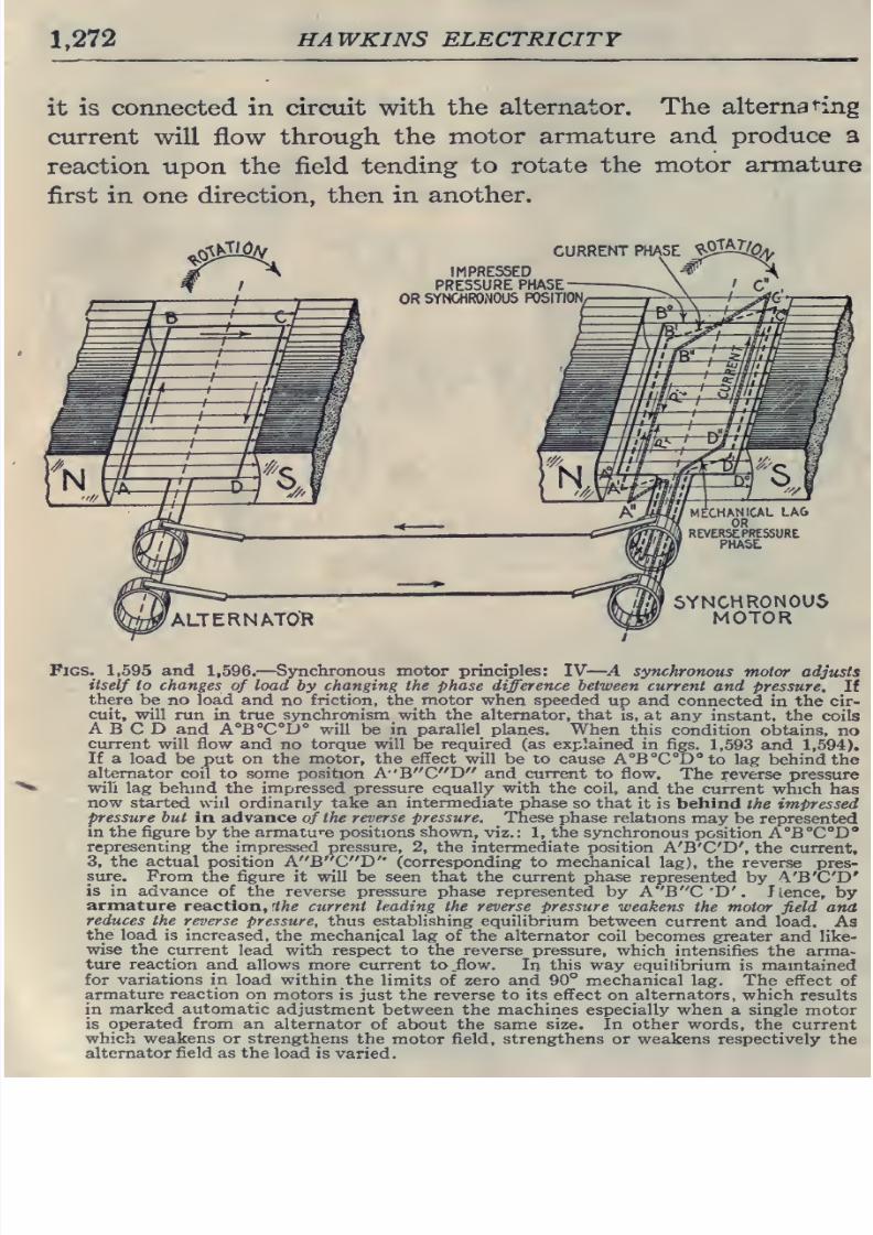
it
is connected
in
circuit with
the alternator.
The
alternating
current
will
flow
through
the
motor
armature and
produce a
reaction
upon
the
field
tending
to
rotate the
motor
armature
first
in
one
direction, then
in
another.
/^
CURRENT PHASE
J^^^^
;
8/20/2019 electrical guide 5.pdf
http://slidepdf.com/reader/full/electrical-guide-5pdf 19/343
ALTERNATING
CURRENT
MOTORS
1,273
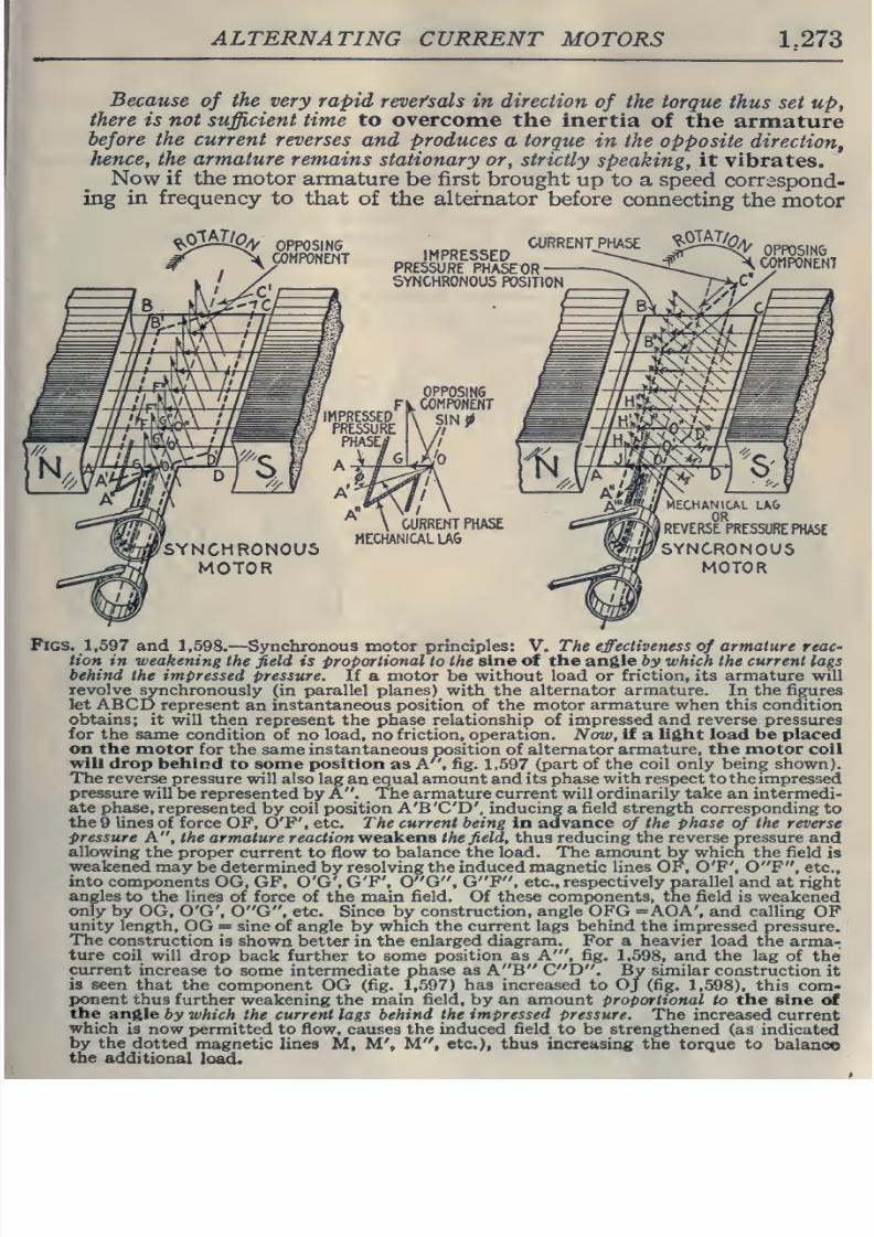
Because
of
the very
rapid
revefsals
in
direction
of
the torque
thus set
up,
there
is
not
sufficient
time to overcome
the
inertia
of
the
armature
before
the current
reverses
and
produces
a
torque
in
the opposite
direction,
hence, the
armature
remains
stationary or,
strictly
speaking,
it
vibrates.
Now
if the motor
armature
be
first
brought
up
to
a
speed
correspond-
ing
in
frequency
to
that
of
the alternator
before
connecting
the
motor
^0W^4,
OPPOSING
COMPONENT
CURRENT
PHASE
IMPRESSED
PRESSURE
PHASEOR
SYNCHRONOUS
POSITION
^owa
^
OPPOSING
COMPONENT
CURRENT
PHASE
MECHANICAL
LA6
SYNCRONOUS
MOTOR
Pigs.
1,597
and 1,598.
—
Synchronous
motor principles:
V.
The
effectiveness
of
armature reaC'
Hon
in
weakening
the
field
is proportional
to
the
sine
of the angle bywhich
the
current
lags
behind
the
impressed
pressure.
If
a
motor
be
without
load
or
friction,
its
armature
will
revolve
synchronously
(in parallel
planes)
with the
alternator
armature.
In
the
figures
let
ABCD
represent
an
instantaneous position of
the
motor
armature
when
this condition
obtains; it
will
then
represent the
phase
relationship of
impressed
and reverse pressures
for
the same
condition of
no
load,
no
friction,
operation. Now,
if
a
light
load be
placed
on
the
motor
for
the
same
instantaneous
position
of
alternator
armature,
the
motor
coil
will
drop behind
to
some
position
as
A'',
fig.
1,597
(part
of
the
coil only
being
shown).
The
reverse
pressure will
also
lag
an
equal
amount
and
its
phase with respect to
the impressed
pressure
will
be
represented by A .
The
armature
current
will
ordinarily
take
an intermedi-
ate phase,
represented
by coil position
A'B'C'D', inducing
a
field
strength
corresponding
to
the
9
lines
of force OF,
O'F', etc.
The current
being in
advance
of
the
phase
of
the
reverse
Pressure A ,
the
armature reaction
v/eskens
the
field,
thus
reducing
the reverse
pressure
and
allowing
the
proper
current
to
flow
to
balance
the load. The
amount
by
which
the
field
is
weakened may
be
determined by
resolving
the induced magnetic
lines
OF, O'F',
0 F , etc.,
into
components
OG,
GF, O'G', G'F',
0 G ,
G F ,
etc.,
respectively
parallel
and at
right
angles
to the
lines
of force of
the
main
field.
Of
these components, the field
is weakened
only
by
OG,
O'G',
0 G ,
etc. Since
by construction, angle OFG =AOA',
and calling
OF
unity
length,
OG
=
sine
of
angle
by
which the
current
lags
behind
the impressed
pressure.
[
The
construction
is
shown
better
in
the enlarged
diagram.
For
a
heavier load the
arma-;
ture
coil
will
drop
back further to
some position
as A' ,
fig.
1,598,
and
the
lag
of
the
cvurent
increase
to
some
intermediate
phase
as
A B
C D .
By
similar
construction
it
is seen
that
the
component
OG
(fig. 1,597)
has
increased
to Oj (fig.
1,598),
this com-
ponent thus
further
weakening
the main
field, by an amount
proportional
to
the sine
of
the
angle
by
which the
current
lags
behind the
impressed
pressure.
The
increased current
which
is
now
permitted to
flow,
causes the induced
field
to
be
strengthened
(as
indicated
by
the
dotted
magnetic
lines
M,
M',
M ,
etc.),
thus increasing
the torque
to
balance
the
additional
load.
8/20/2019 electrical guide 5.pdf
http://slidepdf.com/reader/full/electrical-guide-5pdf 20/343
1.274
HAWKINS
ELECTRICITY
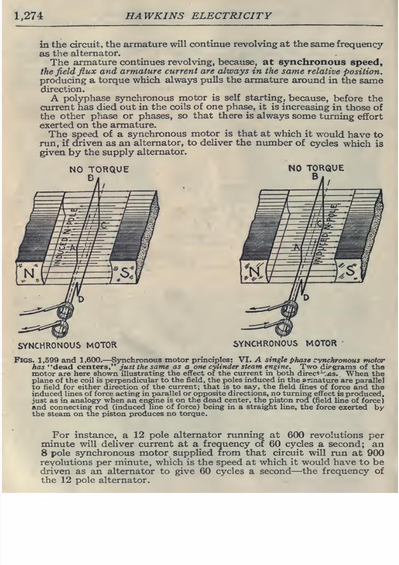
in
the
circuit,
the
armature
will
continue
revolving
at
the
same
frequency
as
the
alternator.
The
armature
continues
revolving,
because,
at
synchronous
speed,
the
field
flux
and
armature
current
are always
in
the
same
relative
position.
producing a
torque which
always
pulls
the
armature
around
in
the
same
direction.
A
polyphase
synchronous
motor
is
self starting,
because,
before the
current
has died out
in the
coils of one phase,
it
is increasing
in
those of
the
other
phase
or
phases,
so
that
there
is always
some
turning
effort
exerted
on
the
armature.
The
speed
of
a
synchronous
motor
is
that
at
which
it
would
have
to
run,
if
driven
as
an
alternator,
to
deliver
the
number
of
cycles
which is
given
by
the supply
alternator.
NO
TORQUE
B
NO
TORQUE
B
SYNCHRONOUS
MOTOR
SYNCHRONOUS
MOTOR
Figs.
1,599
and
1,600.
—
Synchronous
motor
principles:
VT.
A
single
phase
cynchronous
motor
has
dead
centers,
just the
same
as
a
one cylinder
steam engine.
Two
dipgrams
of
the
motor
are
here
shown illustrating
the
effect
of the
current in
both direct^^as.
When
the
plane of
the
coil
is
perpendicular
to
the
field,
the
poles induced in
the
armature
are parallel
to
field for
either
direction of
the
current;
that
is to say,
the
field
lines
of
force and
the
induced
lines
of
force acting in
parallel or opposite directions, no turning
effect
is
produced,
just as in
analogy
when
an
engine
is on
the
dead center,
the
piston
rod
(field
line of
force)
and connecting
rod (induced
line
of
force)
being
in a
straight line,
the force
exerted
by
the
steam on
the piston
produces
no
torque.
For
instance,
a
12
pole
alternator running
at
600 revolutions
per
minute
will
deliver
current
at
a
frequency
of
60
cycles
a second;
an
8
pole synchronous
motor supplied
from that circuit
will
run
at
900
revolutions
per
minute,
which is the
speed
at
which
it
would have
to be
driven
as
an
alternator
to
give 60 cycles
a
second
—
the
frequency
of
the
12 pole alternator.
8/20/2019 electrical guide 5.pdf
http://slidepdf.com/reader/full/electrical-guide-5pdf 21/343
ALTERNATING
CURRENT
DIAGRAMS
1,275
H0T4^,
ALTERNATOR
im/n
A'^
I
PHASE DIFFERENCE
^
LESS
TH.VN
90«
*
MOTOR
CONTINUES
IN OPERATION.
EXTERNAL
CIRCUIT
ALTERNATOR
SYNCHRONOUS
MOTOR
,
ALTERNATOR
^^
PHASE DIFFERENCE
GREATER
THAN
90»
MOTOR
STOPS
EXTERNAL
CIRCUIT
ALTERNATOR
SYNCHRONOUS
MOTOR
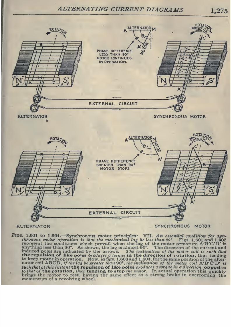
Figs.
1,601
to
1,604.
—
Synchronous
motor
principles*
VII.
An
essential
condition
for
syn-
chronous
motor
operation
is that
the
mechanical lag
be
less
than
90°.
Figs.
1,601
and
1,«02
represent
the
conditions which
prevail
when the
lag of the motor
armature
A'B'C'D'
is
anything
less
than
90°.
As
shown, the
lag is almost
90°.
The
direction
of the current and
induced
poles
are
indicated
by
the
arrows. The
inclination
of
the motor coil is
such
that
the
repulsion
of like
po'es produces
a torque in the direction
of
rotation,
thus
tending
to
keep
motor
in
operation.
Now,
in
figs.
1
,603 and
1
,604 ,
for
the
same
position of
the
alter-
nator
coil
ABCD,
if
the
lag
be
greater
than
90°,
the inclination
of
the motor
coil
A'B'C'D'
is
such
that at
this
instant
the
repulsion
of
like
poles
prodtues
a
torque
in
a
direction
opposite
,
to
that
of
the
rotation,
thus
tendin(i to
stop
the motor.
In
actual
operation
this
quickly
brings the
motor
to
rest,
having
the same
effect as a
strong brake
in
overcoming
the
tnomentum
of
a
revolving
wheel.
8/20/2019 electrical guide 5.pdf
http://slidepdf.com/reader/full/electrical-guide-5pdf 22/343
HAWKINS
ELECTRICITY
MECHANICAL
LAG
CONS;-.
SYNCHRONOUS
POSITION^
^''^
ALTERNATOR
SYNCHRONOUS
MOTOR
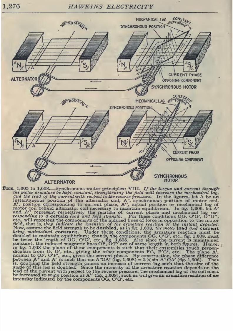
1,605 to 1,608
—
Synchronous
motor principles: VIII.
If
the
torque
and
current
through
the motor armature
be
kept
constant, strengthening the
field
will
increase the
mechanical
lag,
and the
lead
of
the
current with
respect
to
the
reverse pressure.
In the
figures,
let
A
be
aa
instantaneous
position
of
the
alternator
coil,
A°,
synchronous
position of
motor
coilr
A',
position
corresponding
to
current
phase. A , actual position
or
mechanical
lag of
motor
coil behind
alternator
coil
necessary
to
maintain equilibrium.
In
fig.
1,606, let
A'
and
A
represent respectively
the relation
of current phase and mechanical
lag cor-
responding
to
a
certain
load
and
field
strength.
For
these
conditions
OG,
O'G',
0 G ,
etc.,
will
represent
the
components
of
the
induced
lines
of
force
in opposition to
the motor
field,
that
is,
they
indicate
the
intensity
of
the
armature reaction at
the instant depicted.
Now, assume
the field
strength to be
doubled, as in fig.
1,608,
the motor load and
current
being
maintained
constant.
Under these
conditions,
the
armature
reaction
must
be
doubled
to
maintain
equilibrium;
that is,
the components
OG, O'G', etc., fig.
1,608, must
be
twice
the
length
of
OG, O'G'', etc., fig.
1,605.
Also
since
the
current
is
maintained
constant, the
induced
magnetic lines OP,
O'F' are of
same
length in
both
figures.
Hence,,
k
in
fig.
1,608
the
plane of
these components
is
such
that
their
extremities
touch
perpen-
diculars
from
G,
G',
etc.,
giving
the other
components
FG,
F'G',
etc.
The
plane
A',
normal
to OF,
O'F',
etc.,
gives the
current
phase.
By construction,
the phase
difference
between A°
and
A'
is such
that sin
A°OA'
(fig.
1,608)
=
2
X
sin
A°OA' (fig.
1,606).
That
is, doubling
the field
strength
causes
an
increase
of
current lag such
that the sine of
the
angle
of
this
lag
is doubled.
Since the intensity of
the
armature
reaction
depends
on
the
lead of
the
current
with
respect
to
the
reverse
pressure,
the
mechanical
lag of
the
coil
must
be
increased
to
some
position
as A
(fig.
1,608),
such as
will
give an
armature reaction of
aa
intensity
indicated
by
the
components
OG, O'G',
etc.
8/20/2019 electrical guide 5.pdf
http://slidepdf.com/reader/full/electrical-guide-5pdf 23/343
8/20/2019 electrical guide 5.pdf
http://slidepdf.com/reader/full/electrical-guide-5pdf 24/343
HAWKINS
ELECTRICITY
starting is
necessary.
A
synchronous
motor
has
a tendency
hunt*
and
requires
intelligent
attention;
also
an
exciting
which
must
be
supplied
from
an
external
source.
Oues.
State
the
advantage
of
synchronous
motors.
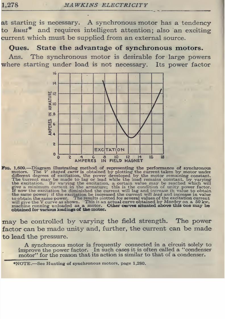
Ans. The
synchronous
motor
is desirable
for large
powers
starting under
load
is not
necessary.
Its
power factor
SIO
<
5.8
8/20/2019 electrical guide 5.pdf
http://slidepdf.com/reader/full/electrical-guide-5pdf 25/343
ALTERNATING
CURRENT
MOTORS
1,279
The
design
of
synchronous
motors
proceeds
on
the
same
lines
as
that of
alternators,
and
the
question
of
voltage
regulation
in the latter
becomes
a
question
of
power factor
regulation
in
the
former.
Oues.
For
what
service
are
they
especially
suited?
Ans.
For
high
pressure
service.
High
voltage
current
supplied
to the
armature
does
not
pass
through
a
commutator
or
slip
rings;
the
field
current
which
passes
through sUp
rings
being
of
low
pressure
does
not
give any
trouble.
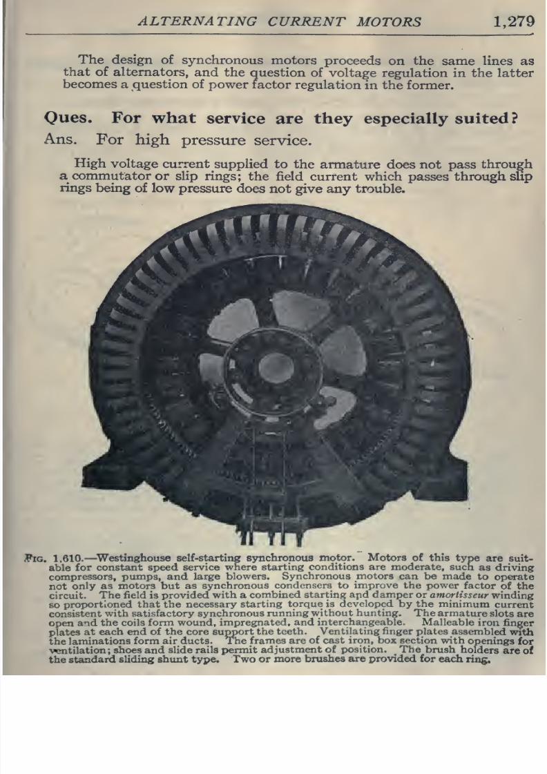
Fig.
1,610.—
Westinghouse self-starting
synchronous
motor.
Motors
of this
type
are suit-
able
for
constant
speed
service where
starting
conditions
are
moderate,
such
as
driving
compressors,
pumps,
and
large
blowers.
Synchronous motors
can be
made
to
operate
not
only as
motors
but
as
synchronous
condensers to
improve
the
power
factor
of
the
circuit.
The field
is
provided
with
a
combined
starting
apd
damper
or amorlisseur
winding
so
proportioned that the necessary
starting
torque is
developed
by
the
minimum
current
consistent
with
satisfactory
synchronous
running
without hunting.
The armature
slots
are
open
and
the
coils
form wound, impregnated,
and
interchangeable.
Malleable
iron
finder
plates
at
each
end
of the core
support
the
teeth.
Ventilating finger
plates
assembled
with
the
laminations
form air
ducts. The
frames are
of cast
iron, box
section with
openings
for
•vcentilation;
shoes
and
slide
rails
permit
adjustment
of position. The
brush
holders
are
of
the standard
sliding
shunt
type.
Two or
more
brushes
are
provided
for
each
ring.
8/20/2019 electrical guide 5.pdf
http://slidepdf.com/reader/full/electrical-guide-5pdf 26/343
8/20/2019 electrical guide 5.pdf
http://slidepdf.com/reader/full/electrical-guide-5pdf 27/343
ALTERNATING
CURRENT
MOTORS 1,281
should
drop
behind that of
the
motor, or
the current
wave
lag
behind,
which
produces the
same
effect,
and due
to
additional
self-induction
or
inductance
produced
by
starting
up
or
over-
loading
some
other
motor
or rotary converter
in
the
circuit.
When
the
motor
is
first
taking
current,
then
giving
current
back
to
the line,
and
this
action
is
continued
periodically, the
motor
is
said
to
be
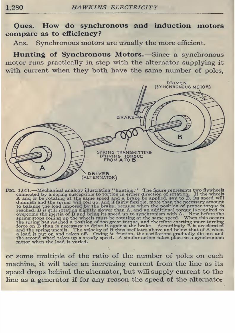
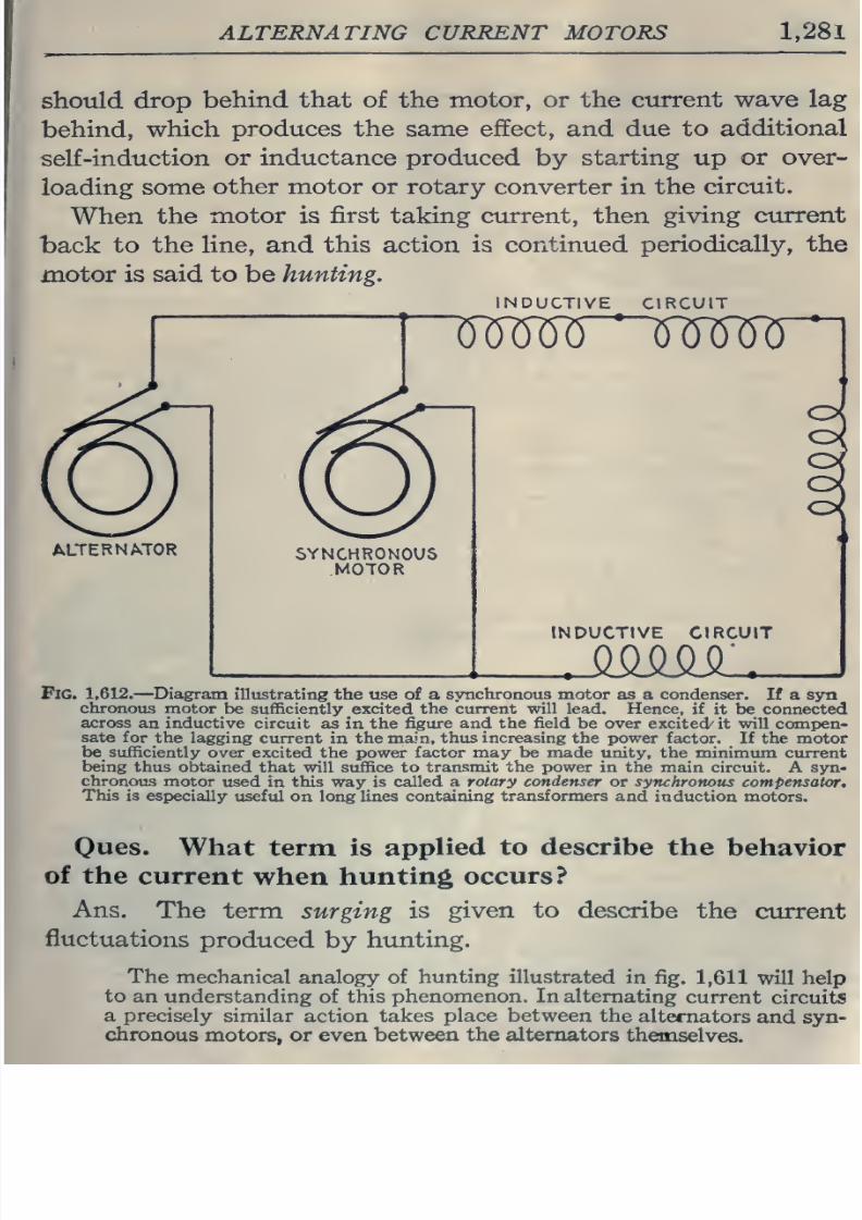
hunting.
NDUCTIVE
CIRCUIT
u^m~^f6Mri
INDUCTIVE CIRCUIT
Fig.
1,612.
—
Diagram
illustrating
the
tise
of
a
synchronous
motor as
a
condenser.
If a
syn
chronous
motor
be
sufficiently
excited
the
current
will
lead.
Hence,
if
it
be connected
across
an inductive
circuit as
in the
figure and
the field
be
over
excited
it
will
compen-
sate for the
lagging
current
in
the main,
thus increasing
the
power
factor.
If
the
motor
be
sufficiently
over
excited the power
factor
may
be made
unity, the
minimum
current
being thus
obtained
that
will suffice
to
transmit
the
power
in
the
main
circuit. A syn-
chronous
motor
used
in
this
way
is
called a
rotary
condenser
or
synchronous
compensator.
This
is especially
useful on long
lines
containing
transformers
and
induction motors.
Ones.
What
term
is
applied to describe the
behavior
of the
current
when
hunting
occurs?
Ans.
The
term
surging
is
given to
describe
the current
fluctuations
produced
by
hunting.
The
mechanical
analogy
of
hunting illustrated
in
fig.
1,611
will help
to
an
understanding
of
this
phenomenon.
In
alternating
current
circuits
a
precisely
similar action
takes
place
between
the
alternators
and
syn-
chronous
motors, or
even
between
the
alternators
themselves.
8/20/2019 electrical guide 5.pdf
http://slidepdf.com/reader/full/electrical-guide-5pdf 28/343
1
,282
HA
WKINS
ELECTRICITY
CHARACTERISTICS
OF
SYNCHRONOUS
MOTORS
Starting.
—
The
motor
must
be
brought
up to
synchronous
speeil
without
load,
a
starting
compensator being
used.
If
provided with
a
self
-starting
device,
the
latter must
be cut
out
of circuit
at
the
proper
time. The starting
torque
of
motor with
self
-starting
device
is
very
small.
Running.
—
^The motor runs
at synchronous
speed.
The maximum
torque
is several
times
full
load
torque
and occurs
at
synchronous
speed*
Stopping.—
If
the
motor receive
a
sudden overload sufficient
to mo-
mentarily
reduce
its
speed,
it
will
stop;
this
may
be
brought
about
by
momentary
interruption
of the
current, sufficient to
cause
a loss of
synchronism.
EfiEect upon
Circuit.
—
In
case of short circuit in
the
line
the
motor
acts
as
a
generator
and
thus
increases
the
intensity
of
the short
circuit.
The
motor impresses
its own wave
form
upon
the
circuit.
Over
excitation
will
give
to the
circuit the
effect of
capacity,
and
under
excitation, that
of inductance.
Power
Factor.—
This
depends
upon
the
field
current, wave
form
and
bunting.
The power
factor may
be
controlled by
varying
the
field excitation.
Necessary
Auxiliary
Apparatus.
—
^Power
for
starting,
or
if
self-
starting,
means
of reducing
the
voltage
while starting;
also,
field
exciter,
rheostat,
friction clutch,
main
switch
and
exciter
switch,
instruments
for
indicating when the field current
is
properly
adjusted.
Adaptation.—
If
induction motors
be
connected
to
the
same
line
with
a
synchronous
motor that
has
a
steady
load, then the field of the
syn-
chronous motor can
be
over
excited
to
produce
a
leading current,
which
will
counteract the effect
of
the lagging currents induced
by the induction
motors.
Owing
to
the weak
starting
torque,
skilled
attendance
re-
quired,
and
the liability
of
the
motor
to
stop
under
abnormal
working
conditions,
the
synchronous motor
is
not
adapted
to
general power
dis-
tribution,
but
rather
to large units which operate under
a
steady
load
and
do
not
require
frequent
starting
and
stoppiug.
8/20/2019 electrical guide 5.pdf
http://slidepdf.com/reader/full/electrical-guide-5pdf 29/343
ALTERNATING
CURRENT
MOTORS 1,283
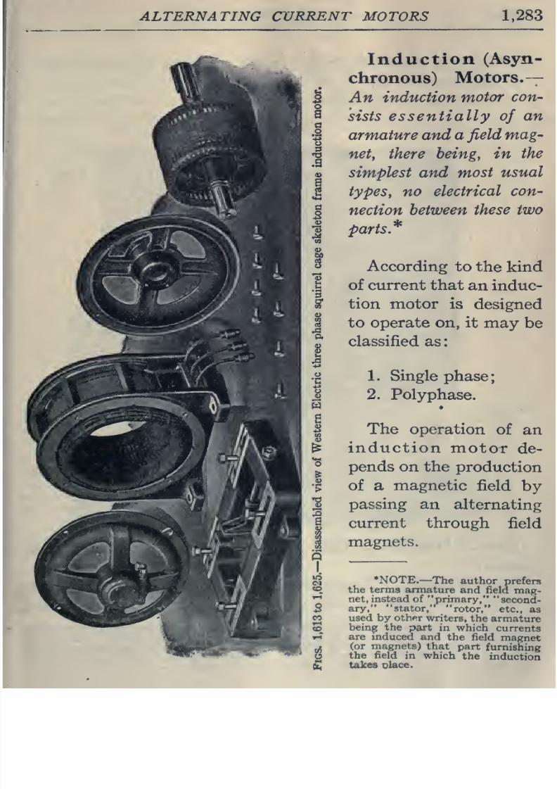
Induction
(Asyn-
chronous)
Motors.-—
An
induction
motor
con-
sists
essentially
of
an
armature and a
field
mag-
net,
there
being,
in
the
simplest
and
most
usual
types,
no
electrical
con-
nection
between
these
two
parts*
According
to
the kind
of current
that
an
induc-
tion motor is
designed
to operate on,
it
may be
classified as
1.
Single
phase;
2. Polyphase.
The
operation
of
an
induction
motor
de-
pends
on the
production
of
a
magnetic
field
by
passing
an
alternating
current
through
field
magnets.
•NOTE.—
The
author
prefers
the
terms
armature
and
field
mag-
net,
instead of
primary,
second-
ary,
stator,
rotor, etc.,
as
used
by
other
writers,
the
armature
bein^ the
part
in which
currents
are
mduced
and
the
field
magnet
(or magnets)
that
part
furnishing
the field
in
which
the
induction
takes
place.
8/20/2019 electrical guide 5.pdf
http://slidepdf.com/reader/full/electrical-guide-5pdf 30/343
1,284
HAWKINS
ELECTRICITY
The
character
of
this
field is
either
1.
Oscillating*,
or
2.
Rotating,
according
as
single
phase or
polyphase current is used.
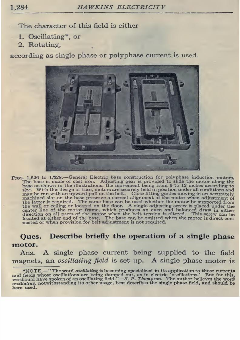
Fjos.
1,626
to
1,^28.—
General
Electric
base construction for
polyphase
induction
motors.
The
base
is
made
of
cast iron. Adjusting
gear
is provided
to
slide
the
motor
along
the
base
as
shown in
the illustrations,
the
movement
being
from
6
to
12 inches
according
to
size.
With
this
design
of base, motors are
securely
held in
position under
all
conditions
and
may
be
run
with an upward pull on
the
belt. Close fitting guides moving
in
an
accurately
machined
slot
on
the
base
preserve
a
correct
alignment of
the
motor
when
adjustment
of
the
latter
is
required. The
same base
can
be
used whether the motor
be
supported
from
the
wall
or
ceiling
or
located
on
the
floor.
A
single
adjusting
screw
is
placed
under
the
center
line of
the
motor
frame,
which
produces an even and balanced
draw
in
either
direction
on
all
parts of the
motor when
the
belt tension
is altered.
This
screw
can
be
located
at
either end
of the
base.
The
base can be
omitted
when
the
motor
is
direct
con-
nected
or
when
provision
for belt
adjustment
is
not
required.
Ques.
Describe
briefly the
operation
of
a
single
phase
motor.
Ans.
A
single
phase
current being supplied
to
the
field
magnets,
an
oscillating
field
is
set
up.
A
single
phase
motor
is
*NOTE.
—
The
word oscillating
is
becoming specialized in its
application
to
those
current^
and
fields
whose
oscillat'ons
are being damped out,
as
in
electric
'oscillations.'
But for
this,
we
should
have
spoken
of
an
oscillating
field.
S.
P.
Thompson. The
author
believes the
word
oscillating,
notwithstanding
its
other
usage,
best
describes
the
single
phase
field,
and
should
be
here
used.
8/20/2019 electrical guide 5.pdf
http://slidepdf.com/reader/full/electrical-guide-5pdf 31/343
ALTERNATING
CURRENT
MOTORS
1,285
not
self
-starting
;
but when
the
armature has
been
set
in
motion
hy
external
means
y
the
reaction
between the magnetic
field
and
the
induced
currents in
the
armature being
no
longer
zero,
a
torque
is
.produced
tending
to
turn
the armature.
The current
flowing
through
the
armature
produces
an
alternating
polarity
such that
the attraction between
the
unHke armature
and
field
poles is
always
in
one direction, thus producing
the
torque.
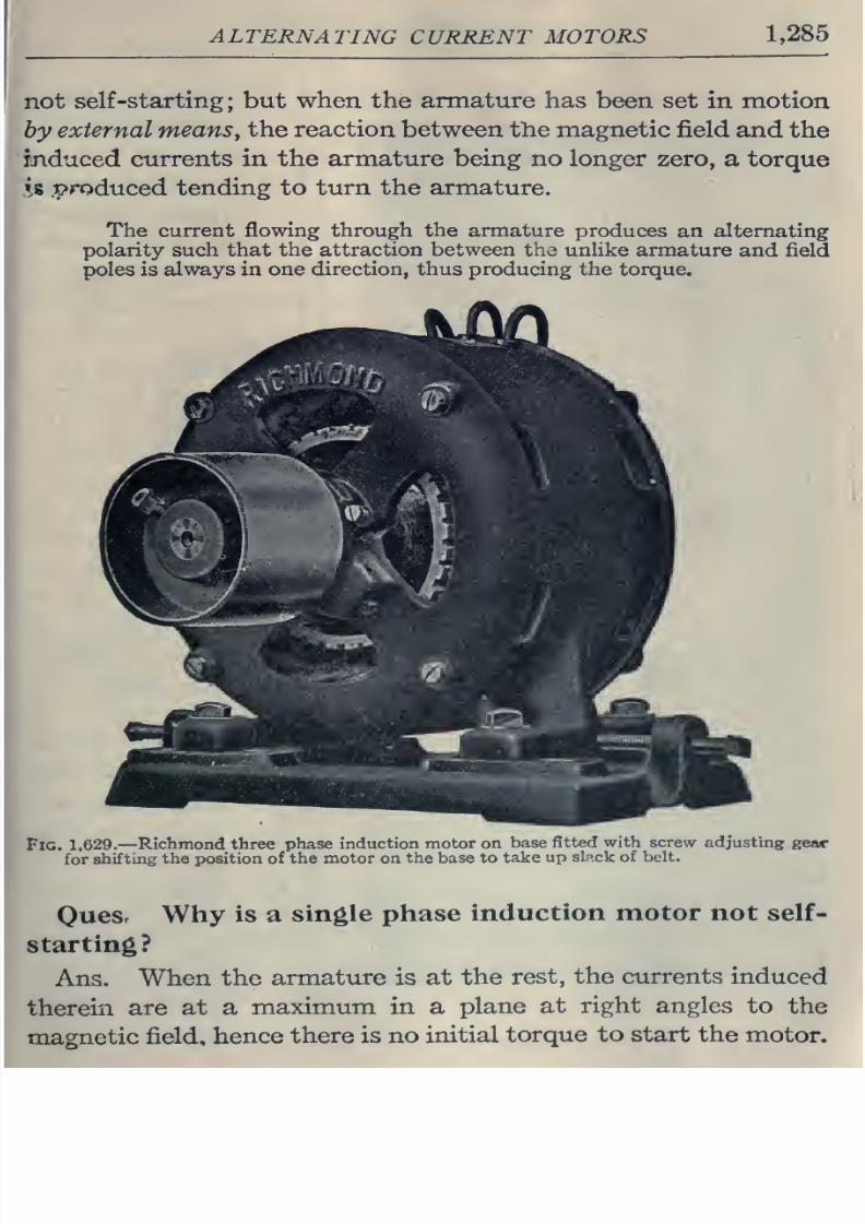
Fig.
1,629.—
Richmond
three phase
induction
motor on
base
fitted
with screw
adjusting
for
shifting
the position of the motor
on
the base
to
take
up
slack of belt.
Ouesr
Why
is
a
single
phase
induction
motor not
self-
starting?
Ans.
When
the
armature
is
at
the
rest,
the currents
induced
therein
are
at
a
maximum
in
a
plane
at
right
angles
to
the
magnetic
field,
hence
there is no
initial
torque
to
start
the
motor.
8/20/2019 electrical guide 5.pdf
http://slidepdf.com/reader/full/electrical-guide-5pdf 32/343
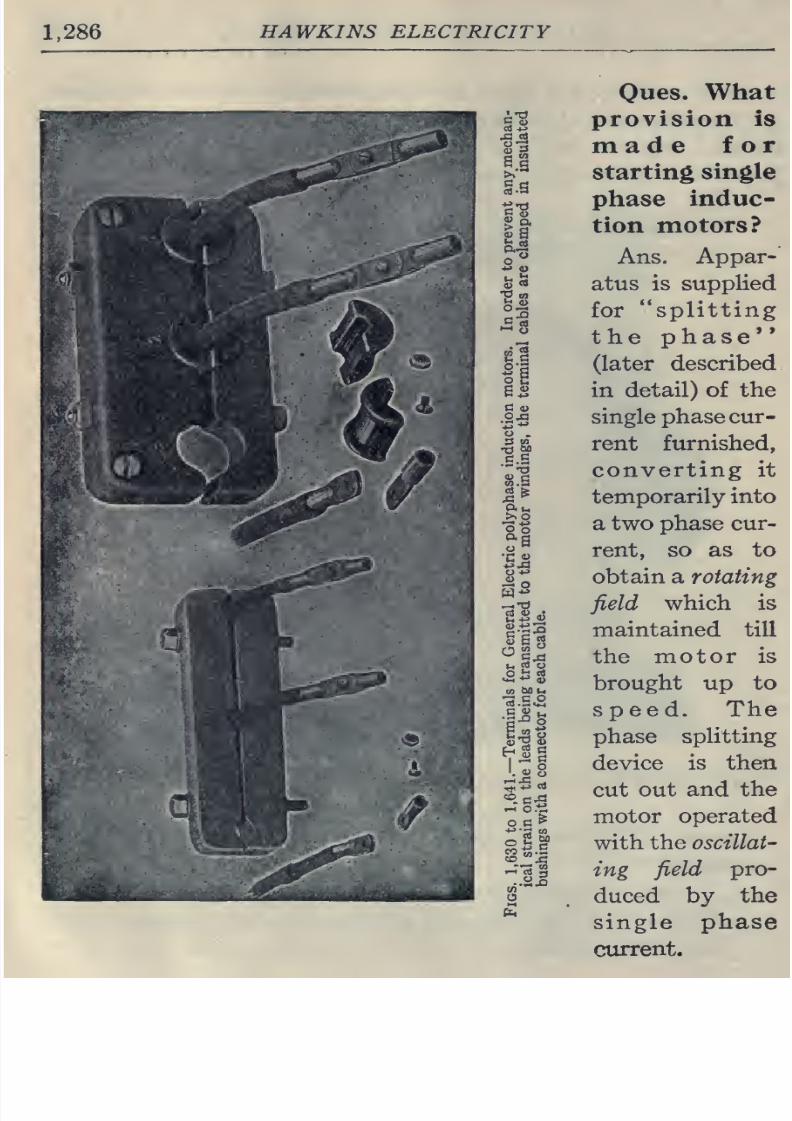
1.286
HAWKINS
ELECTRICITY
o
.
c.S
0)
c
I'
So
u
rt
o
tn
tsot-i
1.^8
o
»-
CD
.
Oues.
What
provision
is
made
for
starting
single
phase
induc-
tion
motors?
Ans.
Appar-
atus is
supplied
for
splitting
the phase'*
(later
described
in
detail) of
the
single
phase
cur-
rent furnished,
converting
it
temporarily
into
a two
phase cur-
rent,
so as
to
obtain a rotating
field
which
is
maintained
till
the
motor
is
brought
up
to
speed.
The
phase
splitting
device is then
cut out
and the
motor
operated
with
the oscillat-
ing
field
pro-
duced
by
the
single phase
current.
8/20/2019 electrical guide 5.pdf
http://slidepdf.com/reader/full/electrical-guide-5pdf 33/343
ALTERNATING
CURRENT MOTORS
1,287
Ques.
Describe briefly the operation
of a polyphase
induction
motor.
Ans.
Its
operation is
due
to
the
production
of
a
rotating
magnetic
field
by
the
polyphase
current
furnished.
This
field
rotating
in space
about
the
axis
of the armature
induces
currents
in
the
latter.
The
reaction
between
these
currents
and
the
rotating
field
creates a torque which
tends
to turn
the
arma-
ture, whether
the
latter be at rest
or
in
motion.
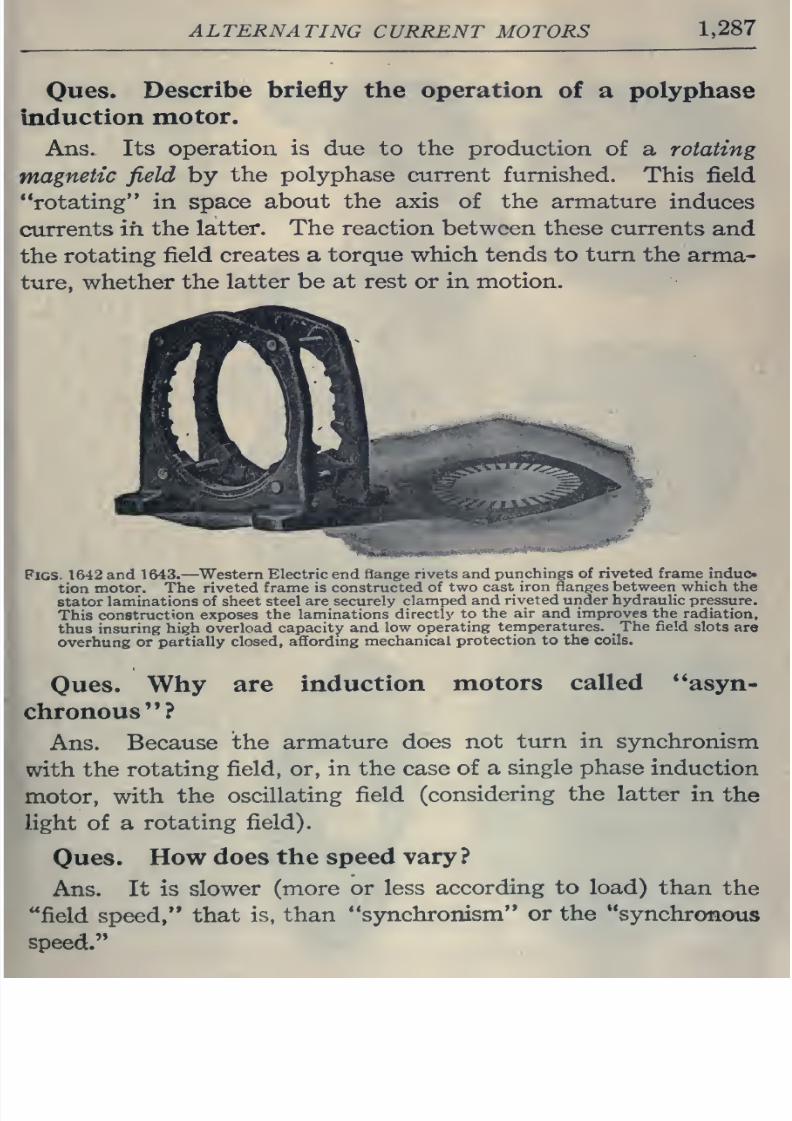
Figs.
1642
and
1643.
—
Western Electric end
flange rivets
and
punchings
of
riveted frame indue
tion
motor. The riveted frame
is
constructed
of
two
cast
iron flanges between which
the
stator
laminations
of
sheet
steel
are securely
clamped
and
riveted
under
hydraulic
pressure.
This
construction
exposes
the
laminations
directly
to
the
air and improves the
radiation,
thus
insuring
high
overload capacity and
low
operating
temperatures.
_
The
field
slots
are
overhung
or
partially closed,
affording
mechanical
protection
to
the
coils.
Ques.
Why
are
induction
motors
called ''asyn-
chronous ?
Ans.
Because
the
armature
does
not
turn in
synchronism
with the
rotating
field,
or,
in
the case
of
a
single phase
induction
motor,
with
the
oscillating
field
(considering
the
latter
in
the
light of
a
rotating field).
Ques.
Howdoes
the speed
vary?
Ans.
It
is slower
(more or
less
according
to load)
than
the
field
speed,
that
is,
than
synchronism
or the
synchronous
speed.
8/20/2019 electrical guide 5.pdf
http://slidepdf.com/reader/full/electrical-guide-5pdf 34/343
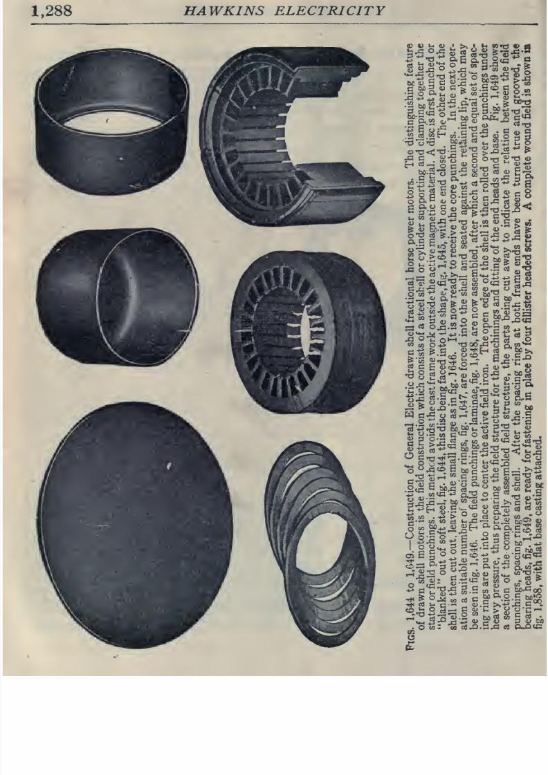
1,288
HAWKINS
ELECTRICITY
<D V
u
u
<
>,
•
»^
eo»rt
V
a
.2
Mi2-c:g
art
c
ti^'^
^-g-i
i^
§1
^^
s-a
«
u
c-o^-a
^
<«
S
c
«
rf
-a
M
o
>>^
r^illiaia|.iH
en
U
8/20/2019 electrical guide 5.pdf
http://slidepdf.com/reader/full/electrical-guide-5pdf 35/343
ALTERNATING
CURRENT
MOTORS
1,289
Oues.
What
is
the
difference
of
speed
called?
Ans.
The
slip.
This
is
a
vital
factor
in
the
operation
of
an
induction
motor,
since
there
must be slip in order
that
the armature
inductors
shall
cut
magnetic
lines to induce
(hence
the
name
*
'induction'*
motor)
currents
therein
so
as to create a
driving
torque.
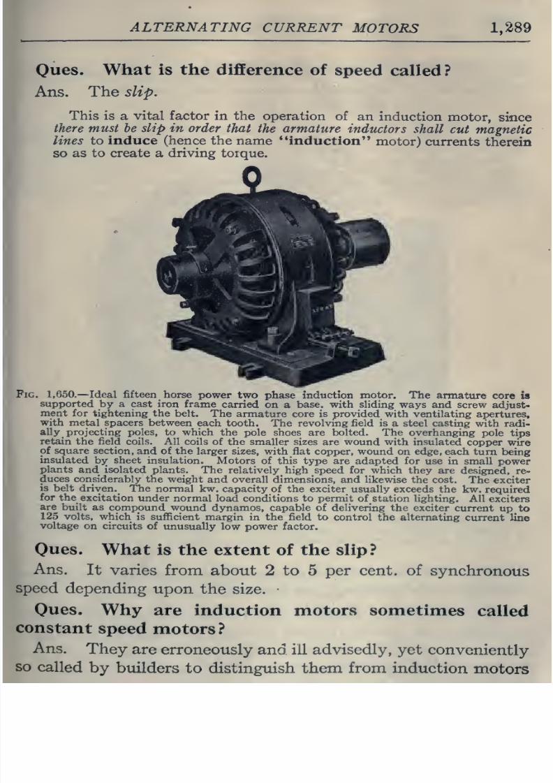
Pig.
1,650.
—
Ideal
fifteen
horse
power two
phase
induction
motor. The
armature
core
is
supported
by
a cast iron
frame
carried
on
a
base,
with
sliding
ways
and
screw
adjust-
ment
for
tightening
the
belt.
The
armature
core
is provided
with
ventilating
apertures,
with
metal
spacers
between
each
tooth.
The revolving field is
a steel
casting
with radi-
ally projecting
poles, to
which
the
pole
shoes
are
bolted. The overhanging
pole tips
retain
the field
coils. All
coils
of the
smaller
sizes
are
wound with insulated
copper
wire
of
square
section,
and
of
the
larger sizes,
with
flat copper, wound
on edge, each
turn
being
insulated
by
sheet insulation.
Motors
of this
type are adapted for use
in small
power
plants
and
isolated plants.
The
relatively
high
speed
for
which
they
are
designed,
re-
duces
considerably the
weight
and
overall
dimensions,
and
likewise
the
cost.
The
exciter
is
belt
driven.
The
normal
kw.
capacity
of
the exciter
usually
exceeds
the
kw.
required
for
the
excitation
under
normal
load
conditions
to
permit
of
station
lighting.
All
exciters
built
as compound
wound
dynamos, capable of
delivering the
exciter
current
up
to
125 volts,
which is
sufficient
margin
in
the field
to control
the alternating
current
line
voltage
on circuits
of
unusually low power
factor.
Oues.
What
is
the
extent
of the slip ?
Ans.
It
varies
from
about
2
to
5
per cent, of
synchronous
speed
depending
upon
the size.
Oues.
Why
are
induction
motors
sometimes
called
constant
speed
motors?
Ans.
They
are
erroneously
and ill
advisedly,
yet
conveniently
so
called
by
builders
to distinguish them
from
induction
motors
8/20/2019 electrical guide 5.pdf
http://slidepdf.com/reader/full/electrical-guide-5pdf 36/343
1,290
HAWKINS ELECTRICITY
fitted
with special
devices to
obtain
widely varying
speeds,
and
which are known
as variable
speed
induction motors.
The
term
adjustable
would
be
better.
Motor,
Constant
Speed.
—
A
motor in which
the
speed is
either
constant or
does
not
materially
vary;
such as
synchronous
motors, induction motors with
small
slip,
and
ordinary
direct current
shunt
motors.—Paragraph
46
of
1907
Standardization
Rules
of
the A.I.E.E.
Motor,
Variable
Speed.
—A
motor
in
which
provision
is made
for
varying
the
spe«d
as
desired.
The
A.I.E.E, has
unfortunately introduced
the
term
varying
speed
motor,
to
designate
motors
in which
the
speed varies with the load, decreasing
when
the
load
increases, such as
series
motors.
The
term is
objectionable,
since by
the
expression
variable
speed
motor
a much
more
general
meaning
is
intended.
.;PlG. 1,651.
—
^Western
Electric core construction
and method of
winding
field
of
skeleton
frame
induction
motor.
The
coils are
wound on forms to
give
them
exact
shape
and
dimensions
required.
They are
pressed
into hot moulds to remove any
irregularities
and
then
the
coils are
imprei^nated
with
hot cement, to
bind the layers
together
in
their per-
manent
shape.
The
portion
of
the
coil
which fits into
the
slot
is
wrapped
with
varnished
cloth
and
a
layer
of
dry
tape
is
wound
over
the
entire
coil.
The
coils
are
then
impregnated
with
an
insulating
compound
and
baked, the
process
being
repeated
six
times.
Coils for
1,100
and
2,200
volt motors
have
an extra covering of
insulation and
double
the
amount
of impregnating and
baking.
The
coils may
be
furnished
with
special
insulation
and
treatment for
exceptionally
severe service
conditions,
such as exposure
to
excessive
moisture,
extreme
heat, acid or
alkaline
fumes,
etc.
The
coils
are
accessible
and for the
final
finish
are sprayed
with black varnish.
Ones.
Why do
some
writers call
the
field magnets
and
armature
the
primary
and
secondary,
respectively?
Ans. Because, in one
sense, the
induction motor
is
a
species
of
transformer,
that
is, it
acts
in
many
respects
like
a trans-
former,
the
primary
winding
of which
is on
the field
and
the
secondary
winding
on
the
armature.
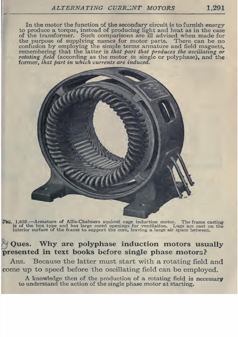
8/20/2019 electrical guide 5.pdf
http://slidepdf.com/reader/full/electrical-guide-5pdf 37/343
ALTERNATING
CuRRZNt
MOTORS
1,291
In
the motor
the function
of
the secondary
circuit
is to
furnish
energy
to
produce
a
torque, instead
of
producing
light and
heat
as
in the
case
of the
transformer. Such
comparisons are
ill advised when
made
for
the purpose
of
supplying
names
for
motor parts. There
can be no
confusion
by employing the simple
terms armature
and
field
magnets,
remembering
that the
latter
is
that
part
that
produces
the
oscillating
or
rotating
field
(according
as
the
motor
^
is single
or
polyphase),
and
the
former,
that
part in which
currents
areinduced.
1,652,—
Annature of AlHs-Chaliners
squirrel
cage
induction
motor.
The
frame
casting
is of
the
box
type and has large cored
openings for ventilation.
Lugs
are
cast
on
the
interior
surface of
the
frame
to
support the core,
leaving
a
large
air
space
between.
Ques,
Why
are
polyphase
induction
motors
usually
in text
books
before
single
phase
motors?
Ans.
Because
the latter
must
start
with
a rotating
field
and
up to
speed before the oscillating
field can
be
employed.
A
knowledge then
of
the
production
of
a
rotating
field
is
necessary
to
understand
the action
of
the
single
phase
motor
at
starting.
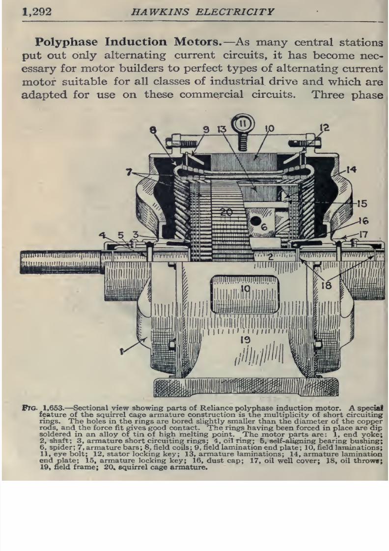
8/20/2019 electrical guide 5.pdf
http://slidepdf.com/reader/full/electrical-guide-5pdf 38/343
1,292
HAWKINS ELECTRICITY
Polyphase
Induction Motors.—
As
many
central
stations
put
out
only
alternating
current circuits,
it
has
become
nec-
essary
for
motor
builders to
perfect
types of
alternating
current
motor
suitable
for
all
classes
of
industrial
drive
and
which
are
adapted
for use
on
these
commercial
circuits.
Three
phase
Pre
1,653.
—
Sectional view showing parts of Reliance
pol3rphase
induction motor.
A special
feature
of the squirrel cage
armature construction is
the multiplicity of
short
circuiting
rings.
The
holes
in
the
rings
are
bored
slightly
smaller
than
the
diameter
of
the
copper
rods, and the
force fit gives good
contact.
The rings
having
been
forced
in
place
are
dip
soldered in
an
alloy
of tin of high melting
point.
The
motor parts are:
1,
end
yoke;
2,
shaft;
3,
armature short
circuiting
rings;
4,
oil
ring;
5,
self-aligning bearing
bushing;
6,
spider;
7,
armature
bars;
8,
field
coils;
9,
field lamination
end plate;
10,
field
laminations;
11,
eye bolt;
12,
stator
locking
key;
13,
armature
laminations;
14,
armature
lamination
end
plate;
15,
armature locking
key;
16,
dust
cap;
17,
oil
well
cover;
18,
oil throws;
19,
field
frame;
20.
squirrel
cage
armature.
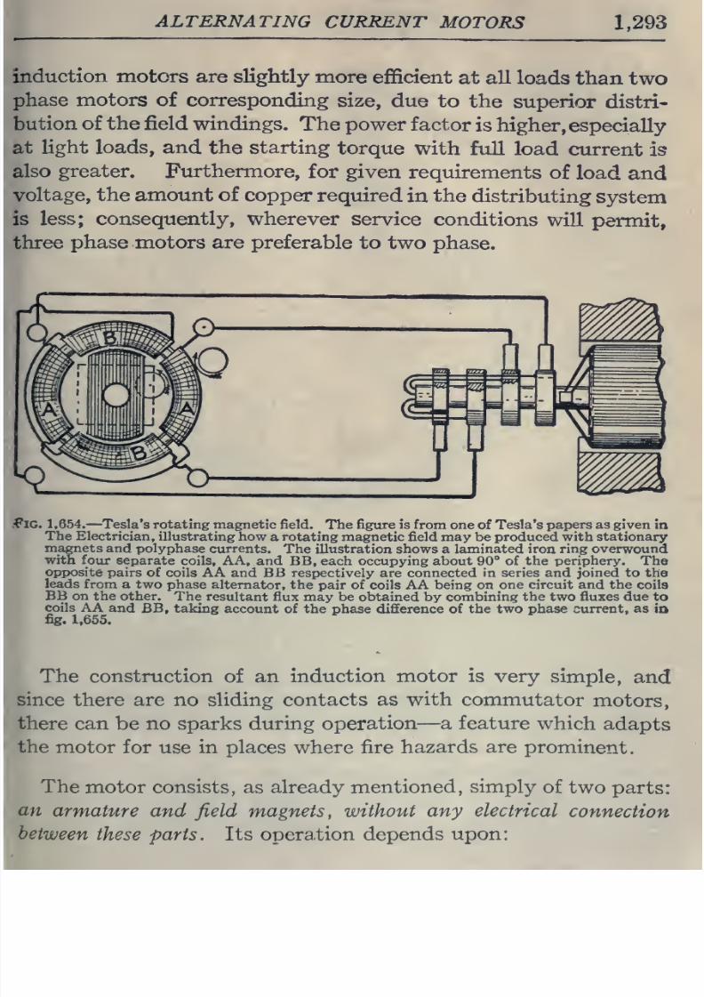
8/20/2019 electrical guide 5.pdf
http://slidepdf.com/reader/full/electrical-guide-5pdf 39/343
ALTERNATING
CURRENT
MOTORS
1,293
induction motors
are slightly
more
efficient
at
all
loads
than
two
phase motors of
corresponding
size,
due
to the
superior distri-
bution
of the field
windings.
The power
factor
is
higher,
especially
at
hght
loads,
and
the
starting
torque
with
full
load
current
is
also greater. Furthermore,
for
given
requirements
of
load
and
voltage, the amount of
copper required
in
the
distributing
system
is
less;
consequently,
wherever
service
conditions
will
permit,
three
phase motors
are
preferable
to
two
phase.
.^^IG.
1
,654.
—
Tesla's
rotating
magnetic field.
The
figure is
from
one
of
Tesla's
papers
as
given
in
The Electrician,
illustrating
how
a
rotating
magnetic field may
be
produced
with
stationary
magnets
and polyphase
currents.
The
illustration shows
a
laminated iron ring overwound
with
four
separate
coils,
AA,
and BB, each
occupying
about
90°
of
the
periphery.
The
opposite
pairs
of
coils
AA
and
BB respectively are
connected
in
series
and
joined
to
the
leads
from
a two
phase
alternator, the
pair
of
coils AA
being on one circuit and
the
coils
BB on the
other.
The
resultant
flux may be obtained
by
combining
the two fluxes due to
coils
AA
and
BB,
taking
account
of
the
phase
difference of
the
two
phase
current,
as
id
fig.
1,655.
The construction
of
an
induction motor
is
very
simple,
and
since
there are no sliding contacts
as
with
commutator
motors,
there
can
be
no sparks
during operation—
a
feature
which
adapts
the
motor
for
use
in places
where fire
hazards
are
prominent.
The
motor
consists,
as
already mentioned,
simply
of
two
parts:
an
armature and
field
magnets, without
any electrical
connection
between
these parts.
Its opera.tion depends
upon:
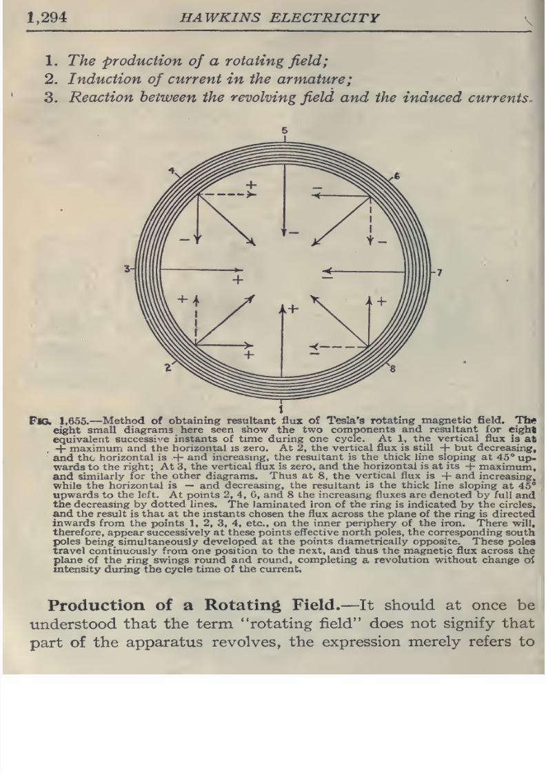
8/20/2019 electrical guide 5.pdf
http://slidepdf.com/reader/full/electrical-guide-5pdf 40/343
1,294
HAWKINS
ELECTRICITY
1. The
production
of
a
rotating
field;
2.
Induction
of
current
in
the
armature;
3.
Reaction
between
the
revolving
field
and
the induced
currents.
Fte.
1,655.—
Method
of
obtaining resultant flux
of
Tesla's
rotating
magnetic
field.
Tl»
eight
small
diagrams
here
seen show
the
two
components
and
resultant
for
eight
equivalent
successi->'e
instants
of time during one
cycle.
At
1,
the
vertical
flux
is
at
+
maximum
and the
horizontal
is
zero.
At
2,
the vertical
flux
is
still
+
but
decreasing,
and
the
horizontal is
+
and
increasing, the resultant
is the
thick
line
sloping at
45°
up-
wards to
the
right;
At
3,
the
vertical flux
is zero,
and
the
horizontal
is at
its
+
maximum,
and
similarly
for the
other
diagrams.
Thus
at
8,
the
vertical
flux is
+
and
increasing,
while
the
horizontal is
—
and
decreasing,
the
resultant
is the
thick
line
sloping
at
45°
upwards
to
the left.
At
points
2, 4,
6,
and
8
the
increasing
fluxes
are
denoted
by
full
and
the decreasing by
dotted
lines.
The laminated
iron
of the ring is
indicated
by
the
circles,
and the
result
is
thai
at the instants
chosen the flux across the plane of the
ring
is
directed
inwards
from
the
points
1, 2,
3,
4,
etc., on
the
inner
periphery of
the iron.
There
will,
therefore,
appear
successively
at
these
points
eff'ective north
poles,
the
corresponding
south
poles
being simultaneously
developed at the points diametrically opposite. These
poles
travel
continuously from
one
position to
the
next, and
thus the
magnetic
flux
across
the
plane
of
the
ring
swings
round
and
round,
completing
a
revolution
without
change
oi
intensity during
the
cycle
time of
the current.
Production
of
a
Rotating
Field.
—
It
should
at once
be
understood
that
the term
rotating field does
not
signify
that
part
of
the
apparatus
revolves, the
expression
merely
refers to
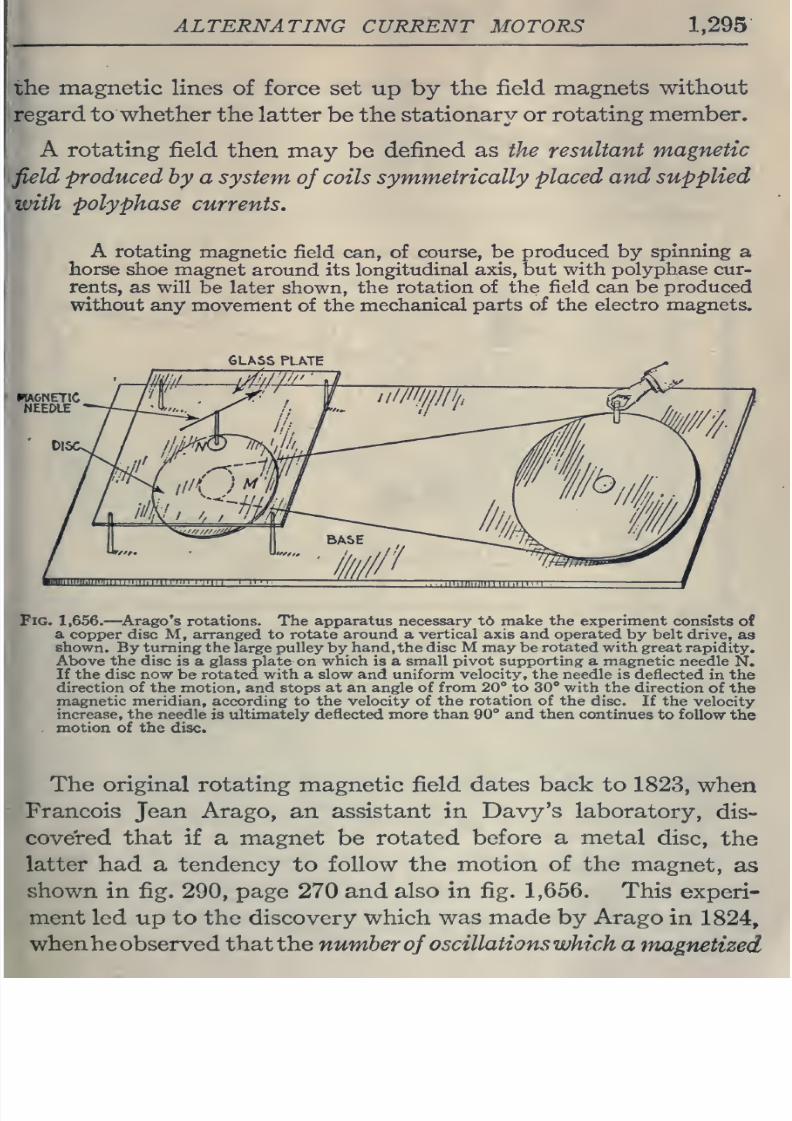
8/20/2019 electrical guide 5.pdf
http://slidepdf.com/reader/full/electrical-guide-5pdf 41/343
ALTERNATING
CURRENT MOTORS
1,295
the
magnetic lines
of force
set
up
by
the field
magnets
without
regard to
whether
the
latter
be
the
stationary or
rotating
member.
A
rotating
field
then may
be
defined as
the resultant
magnetic
field
produced
by
a
system
of
coils symmetrically
placed
and
supplied
with
polyphase
currents.
A
rotating
magnetic
field
can, of
course,
be
produced
by
spinning
a
horse shoe
magnet
around its
longitudinal
axis,
but
with
polyphase
cur-
rents,
as
will
be
later shown,
the
rotation
of
the
field can
be produced
without any
movement
of
the
mechanical parts
of
the
electro magnets.
GLASS
PLATE
Fig.
1,656.
—^Arago's
rotations.
The apparatus necessary
t6
make
the
experiment
consists
of
a
copper
disc
M,
arranged
to
rotate
around
a
vertical axis and operated
by
belt
drive,
as
shown.
By
turning
the
large pulley
by
hand, the disc M may
be
rotated
with
great rapidity.
Above the disc
is a
glass plate
on
which
is a
small pivot
supporting
a magnetic
needle
N.
If the
disc
now
be
rotated with a slow and uniform
velocity,
the
needle is
deflected
in
the
direction of
the
motion,
and
stops
at
an
angle
of
from
20°
to
30
with
the
direction
of
the
magnetic meridian,
according
to
the velocity of
the
rotation
of
the
disc.
If
the
velocity
increase,
the
needle
is
ultimately
deflected
more
than
90°
and then
continues
to follow
the
.
motion
of
the
disc.
The
original
rotating
magnetic
field
dates
back
to
1823,
when
Francois
Jean
Arago,
an
assistant
in
Davy's laboratory,
dis-
covered that
if
a
magnet
be
rotated
before a metal
disc,
the
latter
had
a
tendency
to
follow the
motion
of
the
magnet,
as
shown in
fig.
290,
page
270
and
also
in
fig.
1,656.
This
experi-
ment
led up to
the
discovery
which
was
made
by
Arago
in
1824,
whenheobserved thatthe
number
of
oscillations
which
a
magnetized
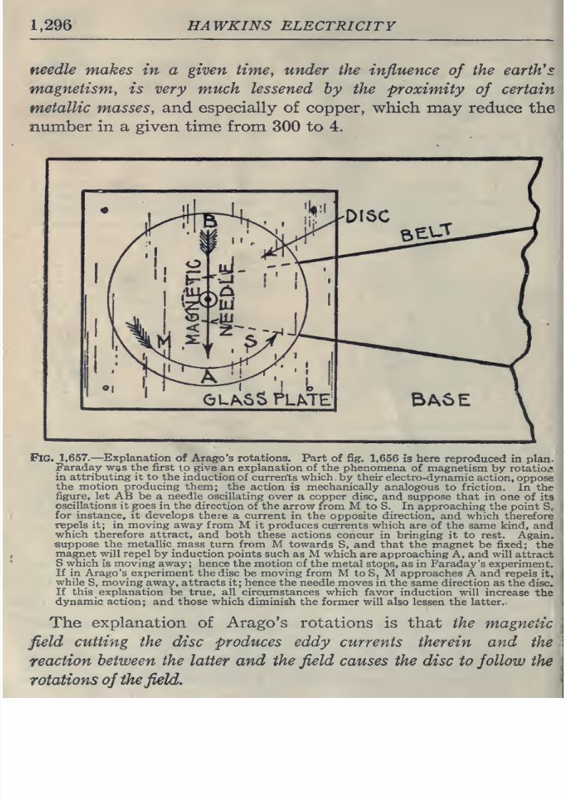
8/20/2019 electrical guide 5.pdf
http://slidepdf.com/reader/full/electrical-guide-5pdf 42/343
1,296
HAWKINS
ELECTRICITY
needle
makes
in
a
given
time,
under
the
influence
of
the
earth^s
magnetism,
is very much lessened
by the
proximity
of
certain
metallic masses,
and
especially of copper,
which may
reduce the
number
in
a given
time
from
300 to 4.
Fig.
1,657.
—Explanation
of Arago's rotations.
Part
of
fig.
1,656
is
here
reproduced in
plan.
Faraday
was
the
first
to
give
an explanation of the phenomena
of
magnetism
by
rotatioij
in
attributing it
to the
induction
of
currents
which
by
their
electro-dynamic
action,
oppose
the
motion
producing
them;
the
action
is
mechanically analogous
to
friction.
In
the
figure,
let AB
be
a
needle
oscillating
over a copper
disc,
and suppose that
in
one
of its
oscillations it goes
in
the
direction of the
arrow from
M
to S.
In
approaching
the
point
S;
for instance, it
develops
there
a
current
in
the opposite
direction,
and
which
therefore
repels it; in moving away from
M
it
produces
currents
which are
of the same kind,
and
which therefore
attract, and
both
these actions
concur
in
bringing
it
to
rest.
Again,
suppose
the
metallic^ mass
turn
from
M towards
S,
and
that the magnet
be
fixed;
the
magnet
will repel
by
induction
points
such
as M
which are approaching
A,
and
will
attract
S which
is
moving
away;
hence
the
motion
of the
metal
stops, as in Faraday's
experiment.
If
in Arago's
experiment the
disc be
moving from
M
to S, M
approaches
A and repels
it,
whiles,
moving away,
attracts
it;
hence the
needle moves
in the same direction as
the
disc.
If
this
explanation
be
true, all
circumstances
which favor
induction
will
increase
the
dynamic
action;
and those which diminish
the former
will
also lessen
the
latter.
The
explanation
of
Arago's rotations
is
that
the
magnetic
field
cutting
the
disc produces eddy currents
therein
and
the
reaction
between
the
latter
and the
field
causes
the
disc
to
follow
the
rotations
of
the
field.
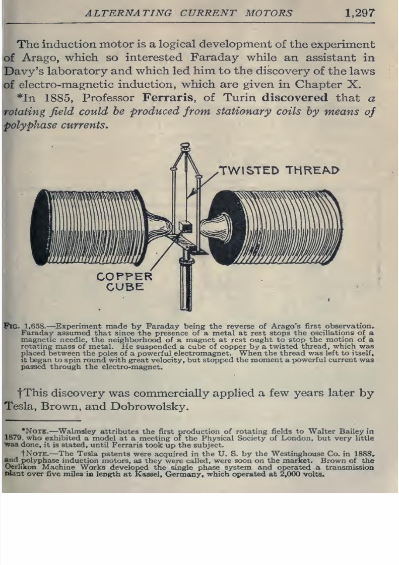
8/20/2019 electrical guide 5.pdf
http://slidepdf.com/reader/full/electrical-guide-5pdf 43/343
ALTERNATING
CURRENT
MOTORS
1,297
The
induction
motor is
a
logical
development
of
the
experiment
Arago,
which
so
interested
Faraday
while
an assistant
in
laboratory and
which
led
him
to
the
discovery
of
the
laws
electro-magnetic
induction,
which
are
given
in
Chapter
X.
*In
1885,
Professor Ferraris,
of
Turin
discovered
that
a
field
could
he
produced
from
stationary
coils
by
means
of
currents.
TWISTED
THREAD
1,658.
—
Experiment
made
by
Faraday
being
the
reverse
of
Arago
's
first
observation,
Faraday
assumed
that since the
presence
of
a
metal at rest stops
the oscillations
of
a
magnetic
needle,
the
neighborhood
of
a
magnet at rest
ought to
stop
the motion of
a
rotating
mass
of
metal.
He
suspended
a
cube
of
copper
by
a
twisted
thread,
which
was
placed
between
the
poles of
a
powerful
electromagnet. When
the thread
was
left
to
itself,
it
began to
spin round with
great
velocity,
but stopped
the moment
a
powerful
current
was
passed
through
the
electro-magnet.
fThis
discovery
was commercially
applied
a few
years
later
by
Brown,
and
Dobrowolsky.
•Note.
—
Walmsley
attributes
the
first
production
of
rotating
fields
to
Walter
Bailey
in
who
exhibited
a
model
at a meeting of the
Physical
Society
of
London,
but
very
little
done,
it is
stated,
until
Ferraris
took
up
the
subject.
tNoTE.
—
The
Tesla patents
were
acquired
in
the
U. S.
by the
Westinghouse Co.
in
1888,
polyphase
induction motors,
as they were called, were
soon on the market. Brown of the
Machine
Works developed
the single
phase system and operated
a
transmission
over
five
miles in
length
at
Kassel,
Germany, which
operated
at 2,000 volts.
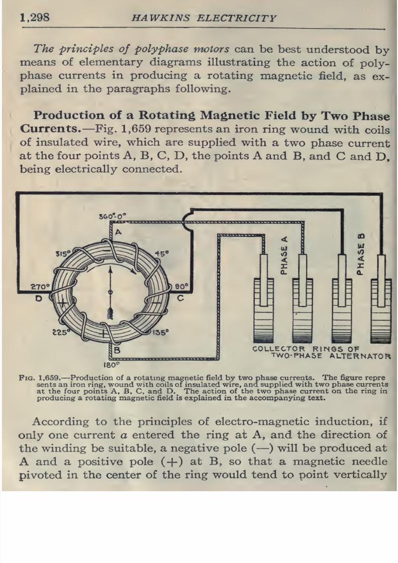
8/20/2019 electrical guide 5.pdf
http://slidepdf.com/reader/full/electrical-guide-5pdf 44/343
1,298
HAWKINS
ELECTRICITY
The
principles
of
polyphase
motors
can
be best
understood
by
means
of
elementary diagrams
illustrating
the
action
of
poly-
phase
currents
in
producing a
rotating
magnetic
field,
as
ex-
plained in the
paragraphs
following.
Production of
a
Rotating
Magnetic
Field
by
Two
Phase
Currents.
—
Fig.
1,659
represents
an
iron
ring
wound
with
coils
of
insulated
wire,
which are
supplied
with
a
two
phase
current
at
the
four points A, B,
C,
D, the
points A
and
B,
and
C
and
D,
being
electrically
connected.
COLLECTOR
RIMGS
OF
TWO-PHASE
ALTERNATOR
180''
Fig.
1,659.
—
Production
of
a rotating
magnetic
field
by
two
phase
currents.
The figure repre
sents
an
iron
ring,
wound with
coils
of insulated
wire,
and
supplied
with
two
phase
currents
at
the four points A, B,
C,
and
D._
The action
of the two
phase
current
on the
ring
in
producing
a
rotating
magnetic
field
is
explained in
the accompanying
text.
According
to
the
principles
of
electro-magnetic
induction, if
only one
current
a
entered
the
ring
at A,
and
the
direction of
the
winding
be
suitable,
a
negative pole
(
—
)
will be
produced at
A
and a
positive pole
(-}-)
at
B,
so that
a
magnetic needle
pivoted
in
the
center
of
the
ring
would
tend to
point
vertically
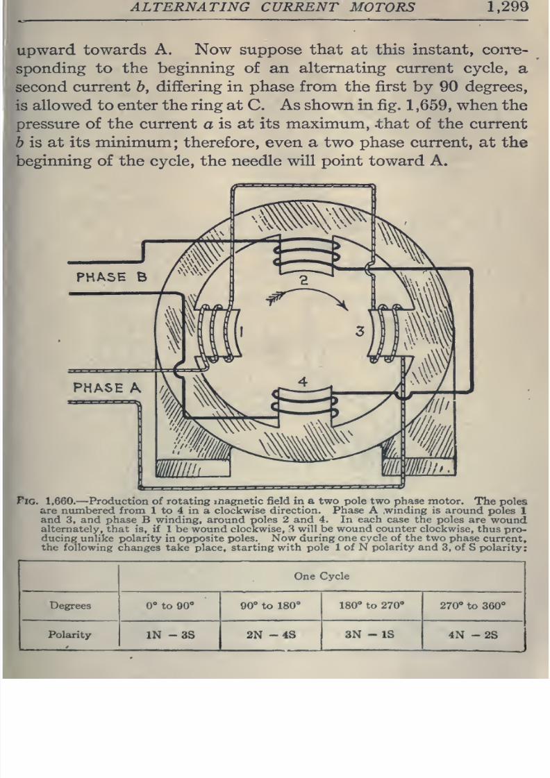
8/20/2019 electrical guide 5.pdf
http://slidepdf.com/reader/full/electrical-guide-5pdf 45/343
ALTERNATING
CURRENT
MOTORS
1,299
upward
towards
A.
Now
suppose
that
at
this
instant,
con'e-
sponding
to
the
beginning
of
an
alternating
current
cycle,
a
second
current
b,
differing
in
phase from the first
by
90
degrees,
is
allowed
to enter the
ring
at
C.
As
shown
in
fig.
1
,659,
when
the
pressure of
the
current
a
is at
its maximum, -that
of
the
current
h
is at its
minimum;
therefore,
even
a
two
phase
current, at
the
beginning of the
cycle, the
needle
will point toward A.
Pig. 1,660.
—
Production
of
rotating inagnetic field
in
a
two
pole
two
phase
motor.
The poles
are
numbered
from 1 to 4 in
a
clockwise direction.
Phase A
.wmding
is
around
poles
1
and
3,
and phase B winding, around
poles 2 and 4. In
each
case the poles
are
wound
alternately,
that
is,
if
1
be
wound
clockwise, 3
will
be
wound counter clockwise,
thus
pro-
ducing unlike
polarity in
opposite
poles.
Now during
one
cycle of the
two
phase
current,
the following
changes
take
place, starting
with
pole
1 of N
polarity and
3,
of
S polarity:
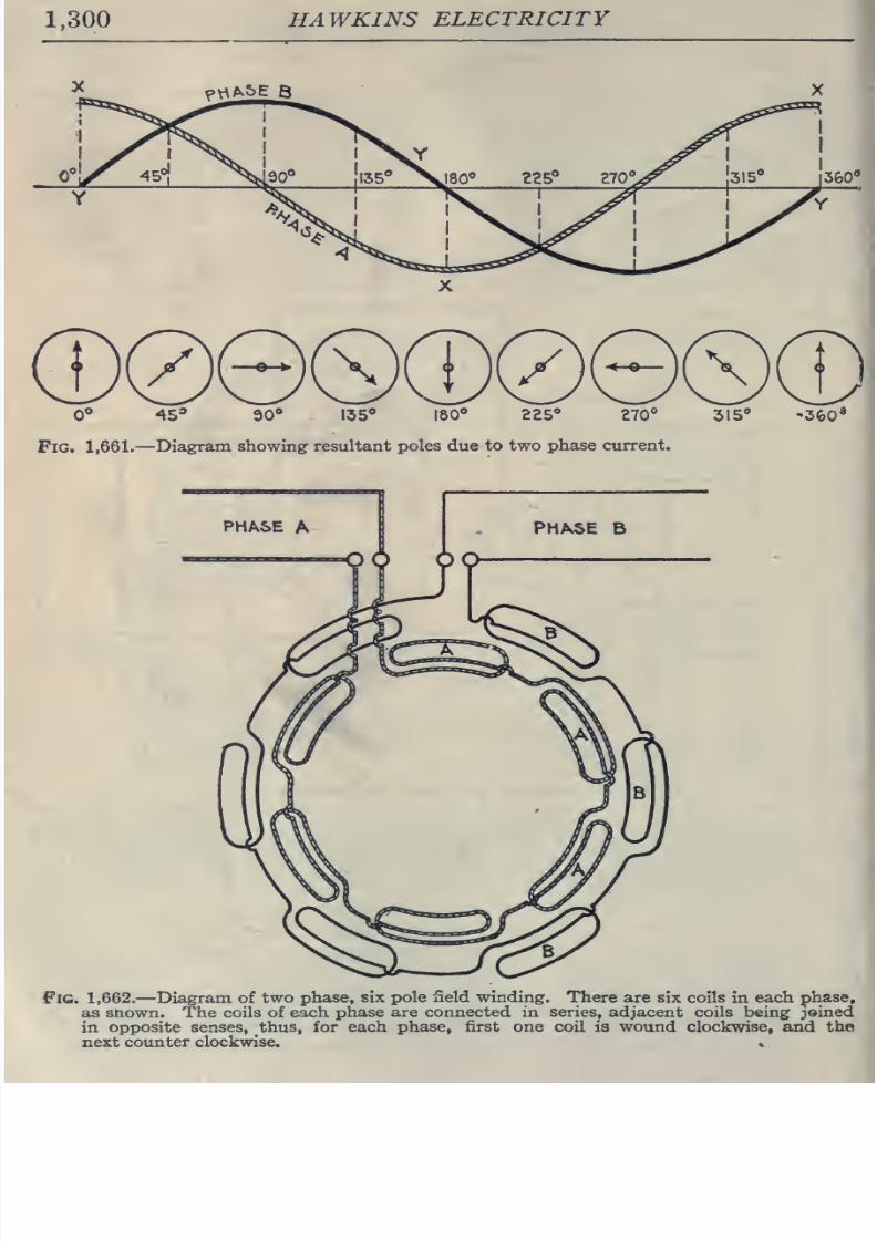
8/20/2019 electrical guide 5.pdf
http://slidepdf.com/reader/full/electrical-guide-5pdf 46/343
1,300
HAWKINS
ELECTRICITY
0**
45*
90*
135
ISO
225
270°
315
Fig.
1,661.
—
Diagram
showing
resultant
poles
due to
two
phase
current.
•360'
Fig.
1,662.
—Diagram
of two
phase,
six pole
field winding.
There
are
six
coils
in
each
phase,
as
snown.
The
coils
of
each
phase are connected
in
series,
adjacent
coils
being
joined
in
opposite
senses,
thus, for each
phase,
first one coil is wound clockwise, and the
next
counter
clockwise.
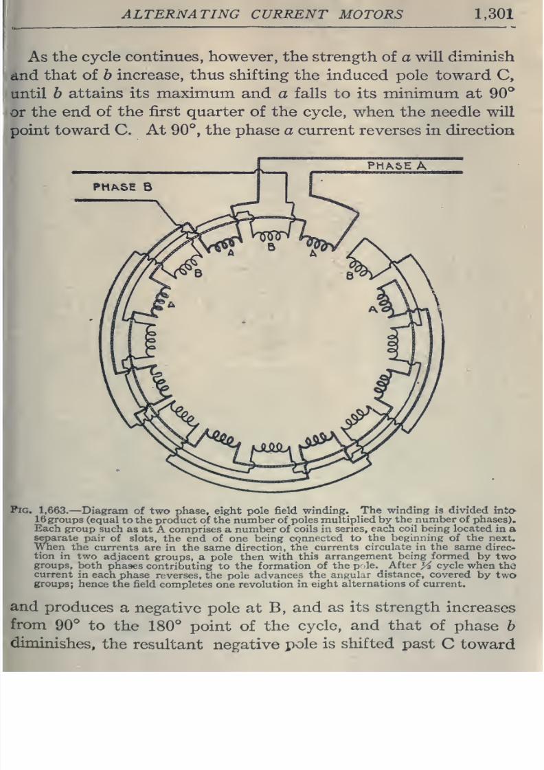
8/20/2019 electrical guide 5.pdf
http://slidepdf.com/reader/full/electrical-guide-5pdf 47/343
ALTERNATING
CURRENT
MOTORS
1,301
As
the
cycle
continues,
however,
the
strength
of
a
will
diminish
and
that
of
b
increase,
thus
shifting
the
induced pole toward
C,
until
h
attains
its
maximum
and
a
falls
to
its
minimum at
90^
or
the
end
of
the
first
quarter
of
the
cycle,
when
the
needle
will
point toward C.
At
90°,
the phase
a
current reverses
in
direction
Pig.
1,663.
—Diagram
of
two
phase, eight
pole
field winding.
The winding
is divided
into
16 groups
(equal
to
the product of the
number
of
poles
multiplied by
the
number of
phases).
Each
group
such
as at
A
comprises
a
number
of
coils
in
series,
each coil being
located
in
a
separate
pair
of
slots,
the
end
of
one
being
cgnnected
to
the beginning
of
the
next,
When
the
currents
are in
the
same direction,
the currents
circulate
in
the
same
direc-
tion
in
two
adjacent
groups,
a
pole
then
with
this
arrangement
being formed
by
two
groups,
both
phases
contributing
to
the
formation
of
the
p.le.
After
yi
cycle when
the
current
in each
phase
reverses,
the pole
advances
the angular
distance,
covered
by
two
groups;
hence
the
field
completes
one
revolution
in
eight
alternations of current.
and
produces
a
negative pole at B,
and as
its strength
increases
from
90°
to
the
180°
point
of
the
cycle,
and
that
of
phase
b
diminishes,
the
resultant
negative
pole
is
shifted
past
C
toward
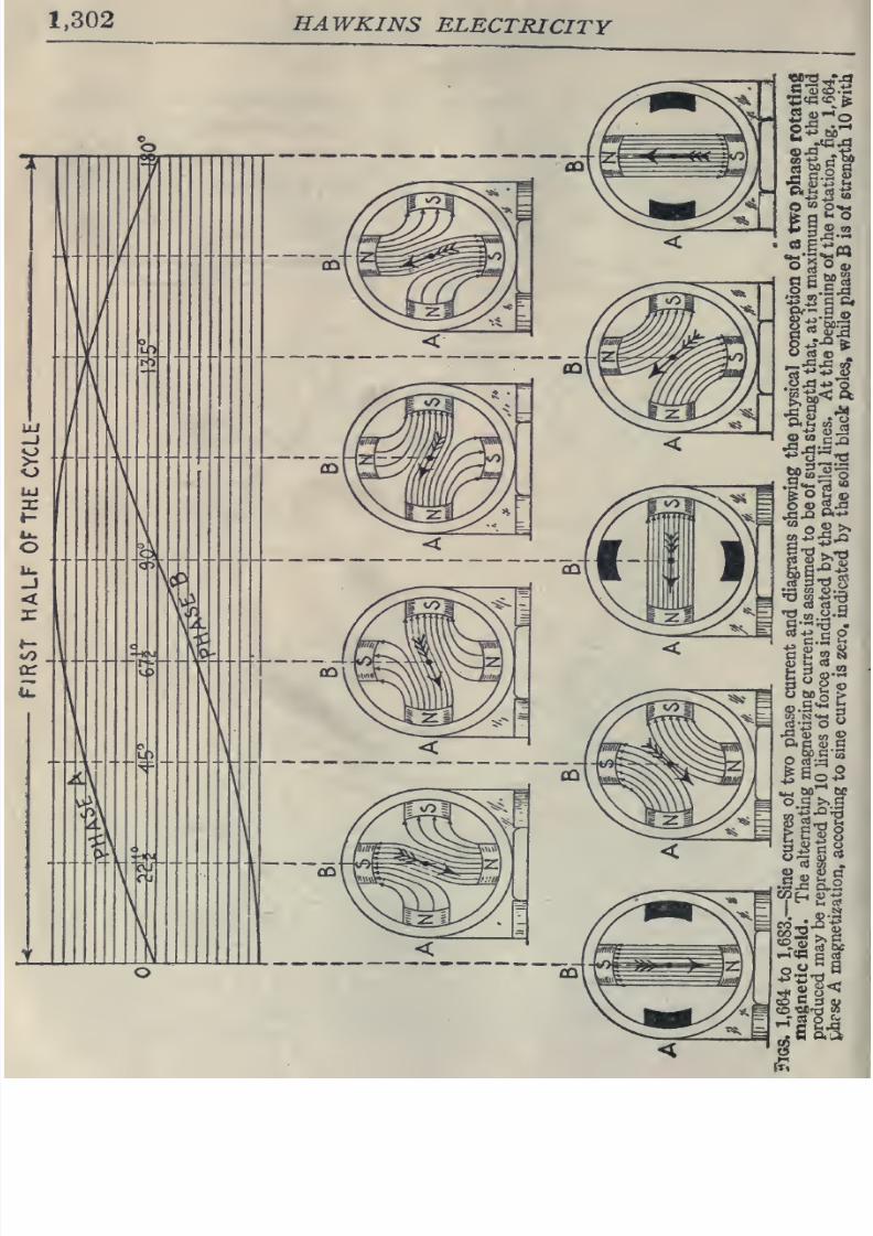
8/20/2019 electrical guide 5.pdf
http://slidepdf.com/reader/full/electrical-guide-5pdf 48/343
1,302
HAWKINS
ELECTRICITY
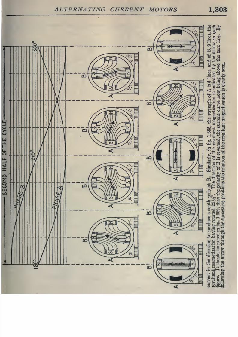
8/20/2019 electrical guide 5.pdf
http://slidepdf.com/reader/full/electrical-guide-5pdf 49/343
ALTERNATING
CURRENT
MOTORS
1,303
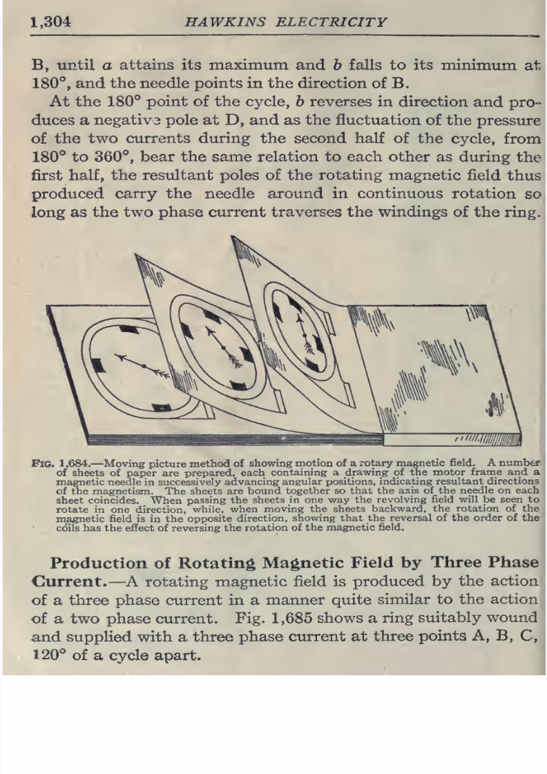
8/20/2019 electrical guide 5.pdf
http://slidepdf.com/reader/full/electrical-guide-5pdf 50/343
1.304
HAWKINS
ELECTRICITY
B,
until
a
attains
its
maximum
and
b
falls to its
minimum
at
180°,
and
the
needle
points
in the
direction
of
B.
At
the
180°
point
of
the cycle,
b
reverses
in direction
and
pro-
duces
a
negativ3
pole
at
D,
and
as
the
fluctuation of
the
pressure
of
the
two
currents during
the second
half
of the
cycle,
from
180°
to
360°,
bear the same relation to
each
other
as
during
the
first
half,
the resultant poles
of
the
rotating
magnetic
field
thus
produced
carry
the needle
around in
continuous
rotation
so
long as
the
two
phase
current
traverses
the
windings
of
the ring.
Pig.
1,684.
—Moving
picture
method
of
showing motion of
a rotary magnetic
field. A
number
of
sheets
of
paper
are
prepared,
each
containing
a
drawing
of
the
motor
frame
and
a
magnetic
needle
in
successively
advancing
angular positions,
indicating
resultant
directions
of
the magnetism.
The
sheets are
bound
together
so
that
the
axis of
the
needle
on
each
sheet
coincides.
When
passing
the
sheets in one way the
revolving
field will be seen to
rotate in
one
direction,
while,
when
moving
the
sheets
backward,
the
rotation
of the
magnetic
field
is in the
opposite
direction,
showing that the
reversal
of the
order
of
the
cciils
has
the
effect
of
reversing the
rotation
of the
magnetic
field.
Production of
Rotating
Magnetic
Field
by
Three
Phase
Current.
—A
rotating
magnetic
field
is
produced
by
the
action
of
a
three phase
current
in a
manner quite
similar to
the action
of
a two
phase
current.
Fig.
1,685
shows
a
ring
suitably wound
and
supplied with
a
three phase
current at
three
points
A,
B,
C,
120°
of
a
cycle apart.
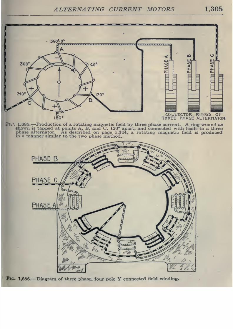
8/20/2019 electrical guide 5.pdf
http://slidepdf.com/reader/full/electrical-guide-5pdf 51/343
ALTERNATING
CURRENT
MOTORS
1,305
COLLECTOR
RIN6S
OF
THREE PHASE
ALTERNATOR
V'n.\
1,685.—Production
of a
rotating
magnetic field
by
three
phase
current.
A
ring
wound as
shown is tapped
at
points
A,
B, and
C,
120°
apart, and
connected
with leads
to
a three
phase alternator.
As
described
on
page
1,304,
a
rotating
magnetic field
is
produced
in a
manner
similar
to
the
two phase method.
PHA5E
E5
Pic.
1,686.
—Diagram
of
three
phase,
four pole
Y
connected
field
winding.
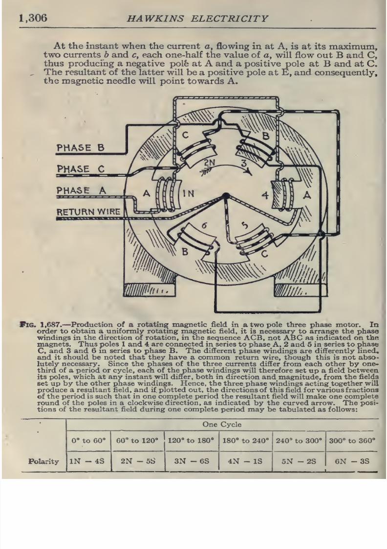
8/20/2019 electrical guide 5.pdf
http://slidepdf.com/reader/full/electrical-guide-5pdf 52/343
1,306
HAWKINS ELECTRICITY
At
the instant
when
the current a,
flowing
in at
A,
is
at its maximum,
two
currents
b
and
c,
each one-half
the
value
of a, will
flow out
B
and
C,
thus
producing a
negative polfe at
A
and a positive
pole at
B
and
at
C.
The
resultant
of
the latter
will
be
a
positive
pole
at
E,
and
consequently,
the
magnetic
needle
will
point
towards
A.
Fig.
1,687.
—
Production of
a
rotating
magnetic
field
in
a
two
pole
three
phase
motor.
In
order
to
obtain a
uniformly rotating
magnetic
field,
it is necessary to
arrange
the
phase
windings in
the
direction
of
rotation,
in
the
sequence
ACB,
not
ABC
as
indicated
on the
magnets.
Thus
poles
1
and
4
are
connected
in series
to phase
A,
2 and 5 in
series
to
phase
C,
and
3
and
6
m
series
to
phase
B. The
different
phase
windings are
differently lined,
and it
should
be
noted that they have a common
return wire, though
this
is
not
abso-
lutely
necessary.
Since
the
phases
of
the
three
currents
differ
from
each
other
by
one-
third
of
a
period
or
cycle, each of the phase
windings
will
therefore
set
up
a
field
between
its
poles,
which
at any instant
will differ,
both in direction
and
magnitude,
from
the fields
set
up
by
the other phase
windings.
Hence, the
three phase
windings
acting
together
will
produce a resultant
field,
and
if
plotted
out,
the
directions
of
this
field for
various
fractions
©f
the
period is such
that
in
one
complete
period
the
resultant field will make
one
complete
round
of the poles
in a
clockwise
direction, as
indicated by
the curved arrow. The
posi-
tions of
the resultant
field during
one complete
period
may
be
tabulated
as follows:
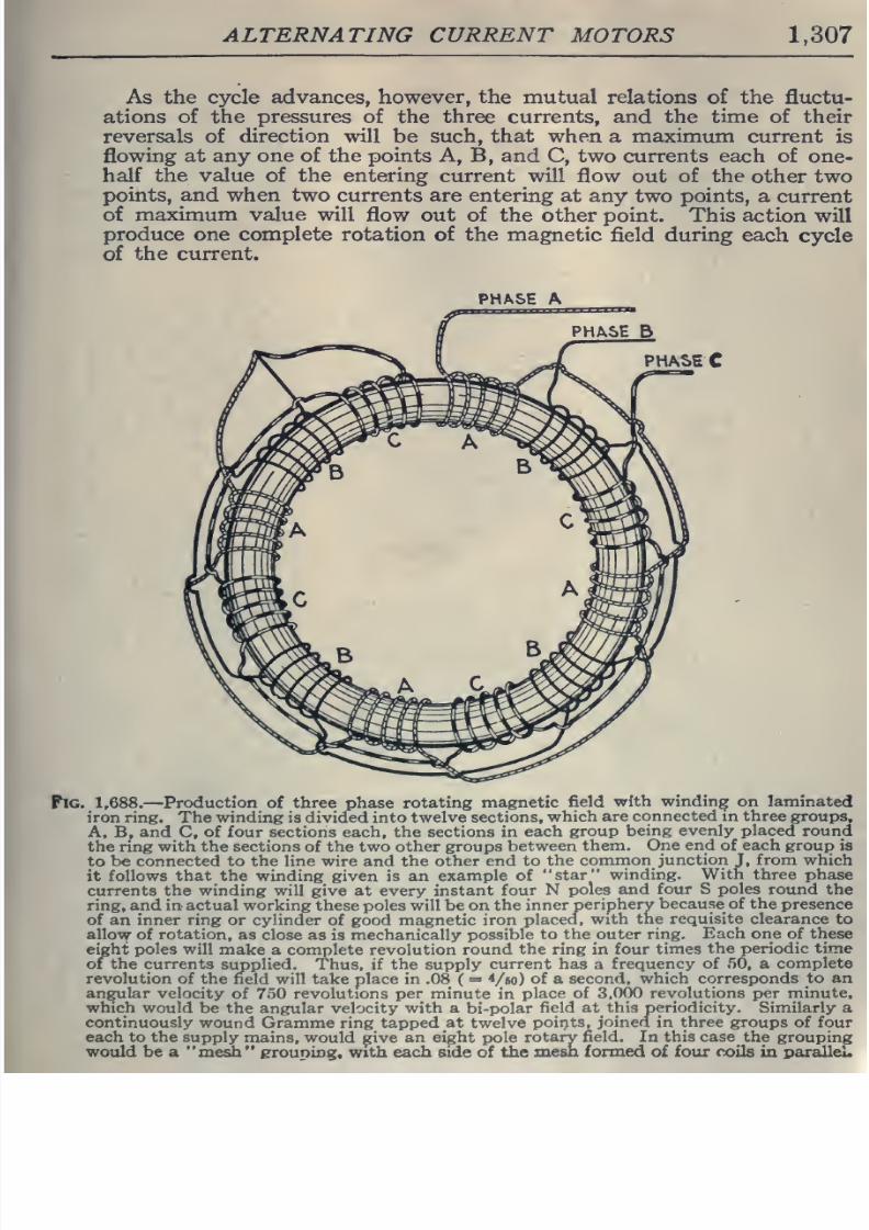
8/20/2019 electrical guide 5.pdf
http://slidepdf.com/reader/full/electrical-guide-5pdf 53/343
ALTERNATING
CURRENT
MOTORS
1,307
As
the cycle
advances, however, the mutual
relations
of
the
fluctu-
ations
of
the
pressures
of the
three
currents,
and
the
time
of their
reversals
of
direction
will
be
such,
that when
a
maximum
current
is
flowing
at any
one
of the points A, B, and
C,
two
currents
each of one-
half
the
value of
the
entering
current
will
flow
out
of
the
other
two
points,
and
when
two
currents are
entering at any
two points,
a
current
of
maximum
value
will
flow
out
of
the
other
point. This
action
will
produce one
complete
rotation of
the
magnetic
field
during
each
cycle
of
the current.
PHASE A
PHA
SE
B
PHASE
Pig.
1,688.
—
Production
of
three
phase
rotating
magnetic
field
with
winding
on laminated
iron
ring.
The
winding
is
divided into
twelve sections,
which
are
connected
in
three
groups,
A,
B,
and
C,
of
four
sections each, the sections in
each
group
being evenly
placed
round
the
ring with
the sections
of
the
two
other groups
between
them. One
end
of
each
group
is
to be
connected
to the line wire
and
the
other
end to
the
common
junction
J,
from
which
it
follows that
the
winding
given is
an
example
of
star
winding.
With
three phase
currents
the winding
will give
at
every instant
four
N
poles
and
four
S
poles
round
the
ring, and in
actual
working
these
poles will be
on
the
inner
periphery
because
of
the
presence
of an inner ring
or cylinder
of
good
magnetic
iron
placed,
with the
requisite
clearance
to
allow
of rotation,
as
close
as
is
mechanically
possible
to
the outer
ring.
Each
one
of
these
eight poles
will
make a complete revolution
round
the
ring in
four times
the
periodic time
of the
currents
supplied.
Thus, if
the
supply
current
has
a
frequency
of
.50,
a
complete
revolution
of
the field will take place in
.08
(
=
Vbo)
of
a
second,
which
corresponds
to an
angular
velocity
of 7o0
revolutions
per
minute
in
place
of
3,000
revolutions
per
minute,
which would
be
the
angular velocity with a bi-polar
field
at
this
periodicity.
Similarly
a
continuously
wound
Gramme ring tapped
at
twelve
points,
joined
in
three groups of four
each
to
the supply
mains, would ^ive
an
eight
pole
rotary
field.
In
this
case
the grouping
would be a medi
erouping,
with
each
side
of
the
mesh formed
of
four coils
in
paralleL
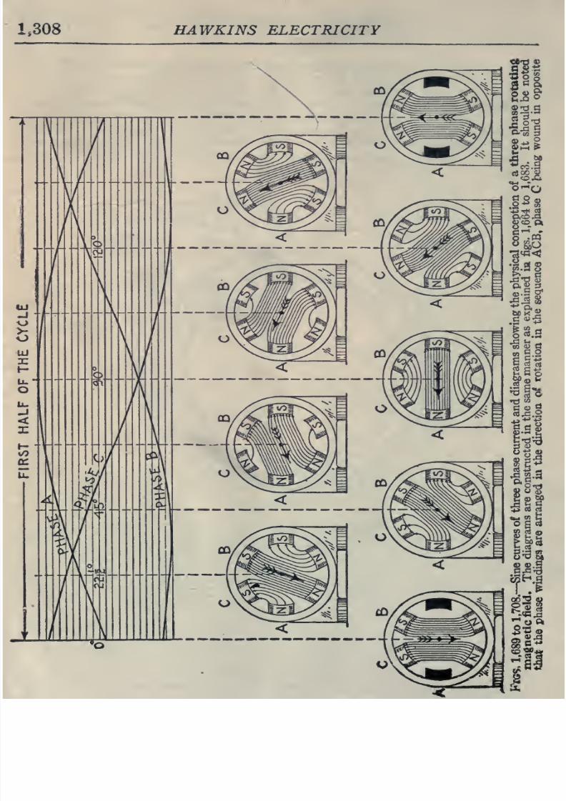
8/20/2019 electrical guide 5.pdf
http://slidepdf.com/reader/full/electrical-guide-5pdf 54/343
1,308
HAWKINS ELECTRICITY
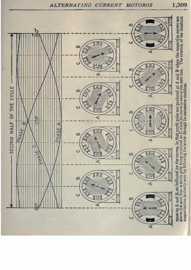
8/20/2019 electrical guide 5.pdf
http://slidepdf.com/reader/full/electrical-guide-5pdf 55/343
ALTERNATING
CURRENT
MOTOROS
1,309
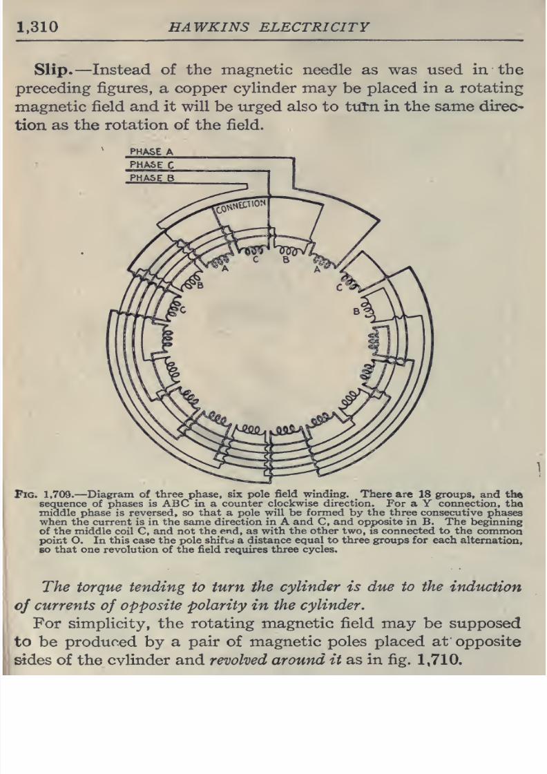
8/20/2019 electrical guide 5.pdf
http://slidepdf.com/reader/full/electrical-guide-5pdf 56/343
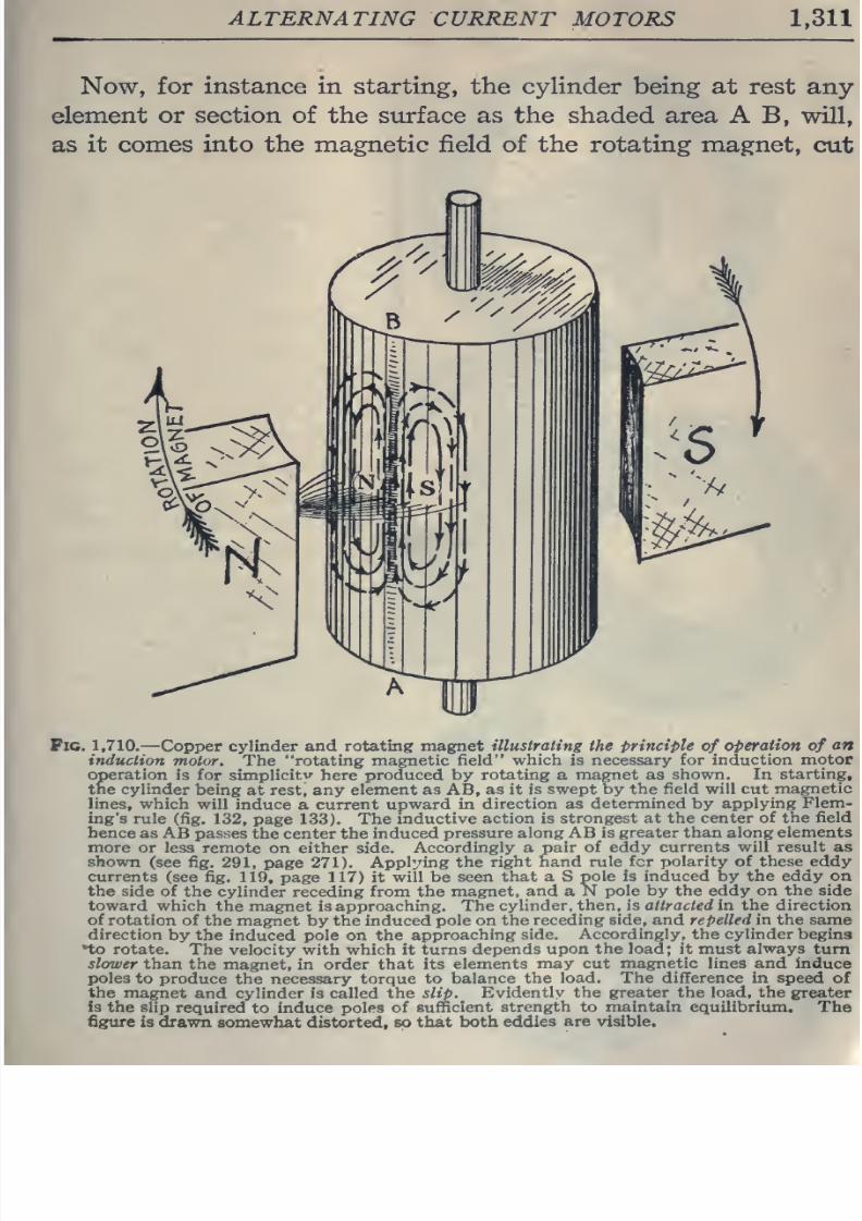
8/20/2019 electrical guide 5.pdf
http://slidepdf.com/reader/full/electrical-guide-5pdf 57/343
ALTERNATING
CURRENT
MOTORS
1,311
Now,
for
instance
in starting,
the
cylinder being at
rest
any
element
or
section of the
surface
as the shaded
area
A B, will,
as it
comes
into the
magnetic field
of
the
rotating
magnet,
cut
Pic.
1,710.
—
Copper
cylinder
and
rotating
magnet
illustrating
the
principle
of
operation
of
an
induction
motor. The rotating
magnetic
field
which is
necessary
for induction
motor
operation
is for
simplicity'- here
produced by
rotating
a
magnet
as
shown. In
starting,
the
cylinder
being
at rest, any
element
as AB, as it
is swept by
the field
will
cut
magnetic
lines,
which
will
induce
a
current
upward in
direction
as
determined
by
applying
Flem-
ing's rule
(fig.
132,
page
133).
The
inductive
action is
strongest at
the
center of
the field
hence
as
AB
passes
the
center the
induced
pressure along AB
is greater
than
along elements
more
or less remote
on either
side.
Accordingly a
pair
of
eddy
currents will result
as
shown
(see
fig.
291,
page
271).
Applying
the
right hand rule
fcr
polarity
of
these eddy
currents
(see
fig.
119,
page
117) it
will
be
seen
that a
S
pole
is
induced
by
the eddy on
the
side
of
the
cylinder receding from
the
magnet, and
a
N
pole by
the
eddy
on
the
side
toward
which
the magnet
is
approaching.
The
cylinder,
then, is a/Zrac/ed in
the
direction
of
rotation
of
the
magnet by
the induced
pole on
the
receding
side,
and repelled
in
the
same
direction
by
the
induced
pole
on
the
approaching
side.
Accordingly, the
cylinder
begins
*to
rotate.
The velocity
with
which
it
turns depends
upon
the
load;
it must always turn
slower than
the
magnet,
in
order
that
its
elements
may cut magnetic
lines
and
induce
poles
to
produce
the
necessary
torque
to
balance
the
load.
The
difference
in
speed
of
the
magnet
and cylinder
is called
the slip.
Evidently
the
greater
the
load, the
greater
is
the slip
required
to induce
poles
of
sufficient
strength to
maintain
equilibrium.
The
figure
is
drawn
somewhat distorted,
so
that
both
eddies are
visible.
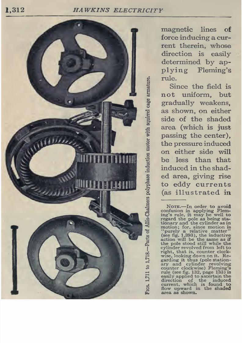
8/20/2019 electrical guide 5.pdf
http://slidepdf.com/reader/full/electrical-guide-5pdf 58/343
1,312
HAWKINS
ELECTRICITY
magnetic
lines
of
force
inducing
a
cur-
rent therein,
whose
direction
is
easily
determined
by ap-
plying
Fleming's
rule.
Since
the
field
is
not uniform,
but
gradually
weakens,
as shown, on
either
side
of the
shaded
area (which is
just
passing
the
center),
the
pressure
induced
on
either
side
will
be less
than that
induced
in
the
shad-
ed
area, giving rise
to eddy currents
(as
illustrated
in
Note.
—
In
order
to
avoid
confusion
in
applying
Flem-
ing's
rule,
it
may be
well to
regard the
pole
as
being
sta-
tionary
and
the
cylinder
as
in
motion; for,
since
motion
is
purely
a relative
niatter
(see
fig.
1,393),
the
inductive
action will
be the same
as
if
the
pole stood still while
the
cylinder
revolved from left to
right,
that
is, counter clock-
wise, looking down on
it.
Re-
garding
it
thus (pole
station-
ary
and cylinder
revolving
counter
clockwise)
Fleming's
rule (see fig.
132,
page
133)
is
easily applied
to ascertain the
direction
of
the
induced
current,
which
is
found
to
flow upward
in
the
shaded
area as
shown.
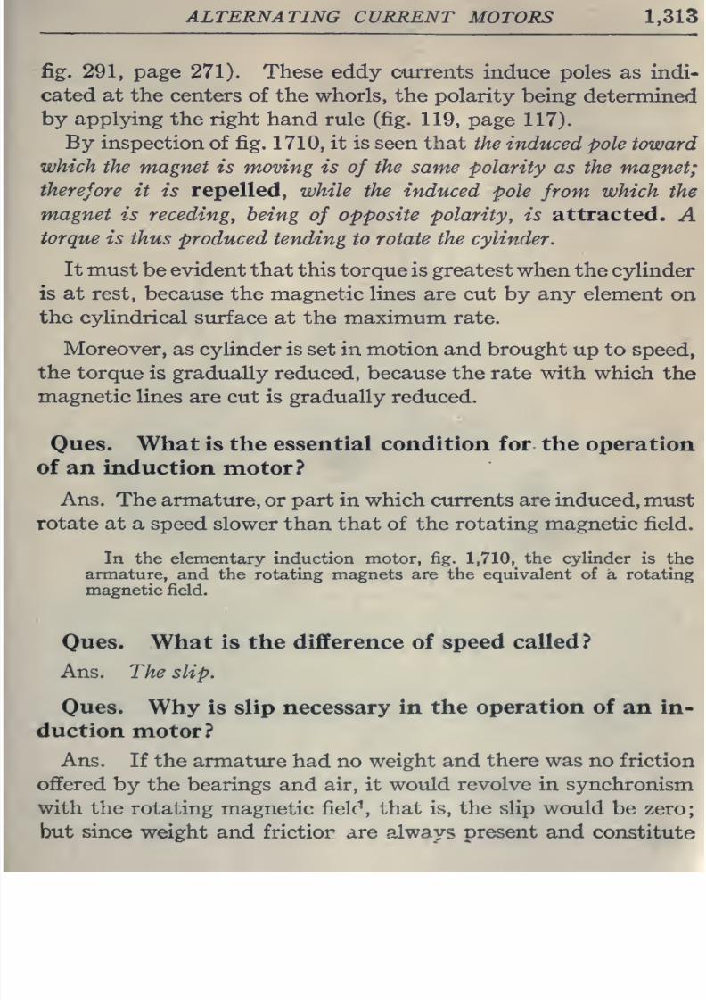
8/20/2019 electrical guide 5.pdf
http://slidepdf.com/reader/full/electrical-guide-5pdf 59/343
ALTERNATING
CURRENT
MOTORS
1,313
fig.
291,
page
271).
These eddy currents
induce
poles
as indi-
cated
at
the
centers
of
the
whorls,
the
polarity
being
determined
by
applying
the right
hand
rule (fig.
119,
page
117).
By
inspection of
fig.
1710,
it
is
seen that
the
induced
pole
toward
which
the magnet
is moving is
of
the
same
polarity
as
the
magnet;
therefore it
is
repelled,
while the
induced
pole
from
which
the
magnet
is
receding,
being
of
opposite polarity, is
attracted.
A
torque
is
thus produced
tending
to rotate
the
cylinder.
It must
be
evident
that
this
torque
is
greatest
when
the cylinder
is
at
rest,
because the
magnetic
lines
are cut
by
any
element
on
the cylindrical
surface
at
the maximum
rate.
Moreover,
as cylinder is set
in
motion
and brought
up
to
speed,
the
torque
is
gradually
reduced, because the
rate
with which
the
magnetic
lines are
cut is
gradually
reduced.
Oues.
What is the essential
condition
for the
operation
of
an
induction
motor?
Ans. The armature,
or part in which currents are
induced,
must
rotate at
a speed
slower
than
that
of the rotating
magnetic
field.
In
the
elementary induction motor,
fig.
1,710,
the
cylinder
is
the
armature,
and
the
rotating magnets
are
the equivalent
of
a
rotating
magnetic field.
Ques.
What
is the difference
of
speed
called
?
Ans.
The
slip.
Oues.
Why is
slip necessary
in
the
operation of
an
in-
duction
motor?
Ans.
If
the
armature
had
no
weight
and
there
was
no
friction
offered
by the bearings
and
air,
it
would
revolve in
synchronism
with
the
rotating
magnetic
fielc',
that
is,
the slip
would
be zero;
but
since
weight
and
frictior are
always
present
and
constitute
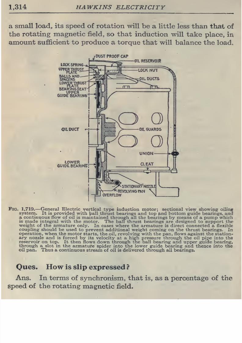
8/20/2019 electrical guide 5.pdf
http://slidepdf.com/reader/full/electrical-guide-5pdf 60/343
1,314
HAWKINS
ELECTRICITY
a
small
load,
its
speed
of
rotation
will
be
a
little
less
than
thai
of
the
rotating
magnetic
field, so
that
induction
will
take
place,
in
amount
sufficient to
produce a
torque
that
will balance
the
load,
^DUST
PROOF
CAP
LOCK
SPRING
UPP^RJViRUSI
OIL
RESERVOIR
Fig.
1,719.
—
General
Electric
vertical
type
induction
motor;
sectional
view showing
oiling
system.
It is provided
with
]pall
thrust
bearings
and
top
and
bottom
guide
bearings,
and
a continuous flow of
oil
is
maintained
through
all the
bearings
by
means
of a pump which
is made
integral with the
motor.
The ball
thrust
bearings are
designed
to
support
the
weight of
the armature
only.
In cases where
the
armature
is
direct connected
a
flexible
couphng
should
be used
to
prevent
additional weight coming on the thrust bearings.
In
operation,
whenthe motor
starts,
the oil, revolving
with
the pan, flows
against
the station-
ary
nozzle
and is
forced
by its
velocity at a high
pressure
through
the
oil
pipe into
the
reservoir
on top.
It then flows
down
through
the
ball
bearing
and upper guide bearing,
through
a
slot
in the
armature
spider into
the lower guide bearing and
thence into the
oil
pan.
Thus
a
continuous
stream
of
oil
is
delivered
through
all bearings.
Ques. How is
slip
expressed ?
Ans. In
terms
of
synchronism,
that
is,
as
a
percentage
of
the
speed
of
the rotating
magnetic
field.
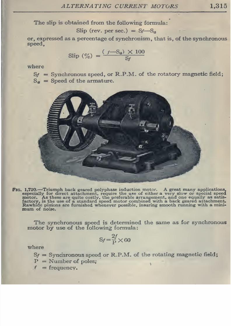
8/20/2019 electrical guide 5.pdf
http://slidepdf.com/reader/full/electrical-guide-5pdf 61/343
ALTERNATING
CURRENT
MOTORS
1,315
The
slip is
obtained
from
the following formula:
Slip
(rev.
per sec.)
=
S/
—
S^
or,
expressed as a
percentage
of
synchronism,
that
is,
of the synchronous
speed,
„,.
,^.
(
/-Sg)
X
100
Slip
(%)
=
g^
where
S/
=
Synchronous
speed,
or
R.
P.M.
of
the
rotatory magnetic
field;
Sa
=
Speed of
the armature.
Pig.
1,720.
—
Triumph
back
geared
polyphase induction motor. A
great
many
applications,
especially
for direct
attachment,
require the
use of
either
a very
slow or special
speed
motor.
As
these are quite
costly,
the
preferable
arrangement,
and
one
equally
as satis«
factory, is
the use
of a
standard
speed
motor combined with a
back
geared attachment.
Rawhide
pinions
are
furnished
whenever
possible,
insuring
smooth
running
with a
mini-
mum
of
noise.
The synchronous
speed is
determined the
same
as
for synchronous
motor
by
use of
the following formula:
2f
S/=j5X60
where
S/
=
Synchronous speed
or
R.P.M.
of
the
rotating magnetic field;
P
=
Number
of poles;
f
=
frequency.
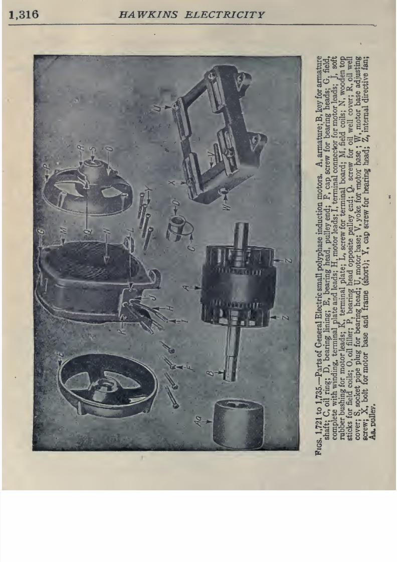
8/20/2019 electrical guide 5.pdf
http://slidepdf.com/reader/full/electrical-guide-5pdf 62/343
1,316
HAWKINS
ELECTRICITY
CO
-g
°^.^
fa w-a
te ^
V
9
Bo
a
.t,* *;
Sp.o2«>sS
&5I
^J
o<fa
M
-5
fc^ M ^
W^^*^
..St)
-^
-gis^^'^JS
^^
8
2'^
8
§4
o
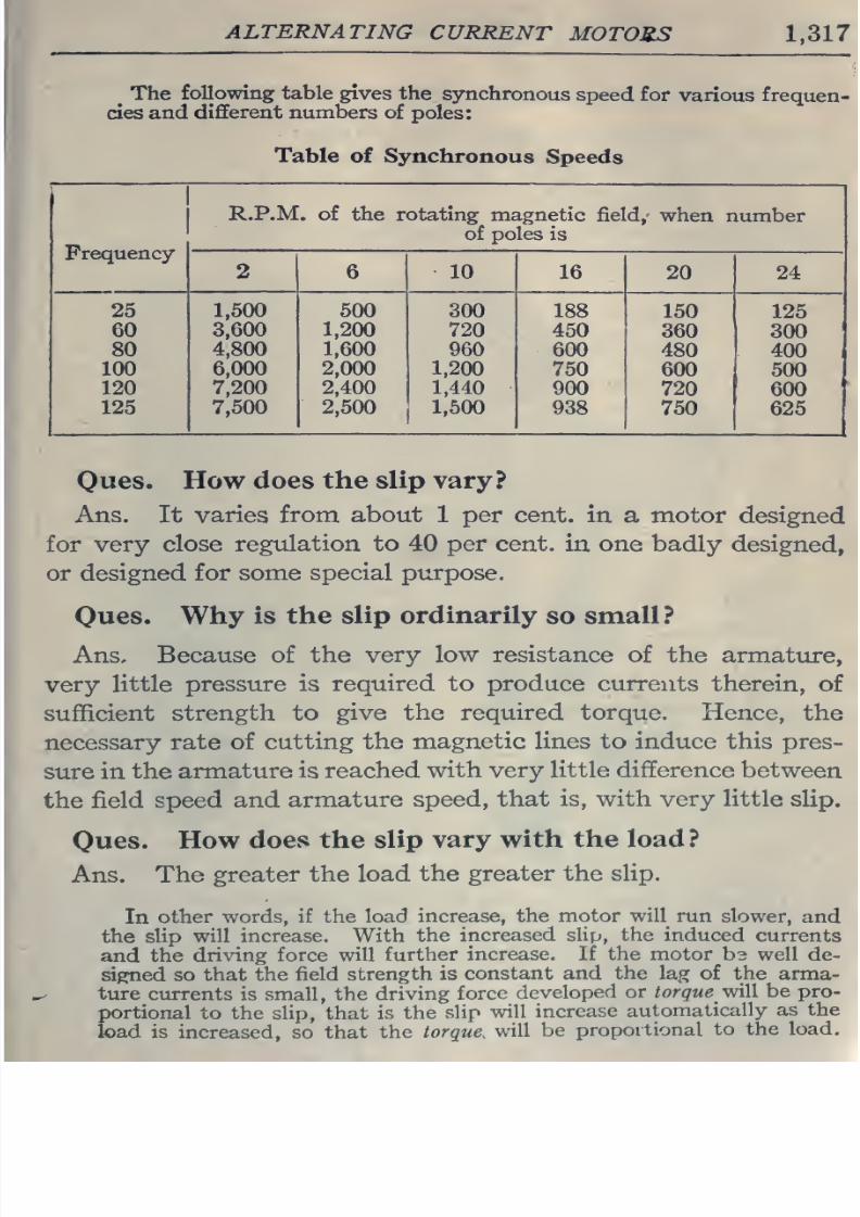
8/20/2019 electrical guide 5.pdf
http://slidepdf.com/reader/full/electrical-guide-5pdf 63/343
ALTERNATING
CURRENT
MOTORS
1,317
^
The
following table gives
the
sjmchronous
speed for
various
frequen-
cies and
different numbers
of
poles:
Table
of Synchronous
Speeds
Frequency
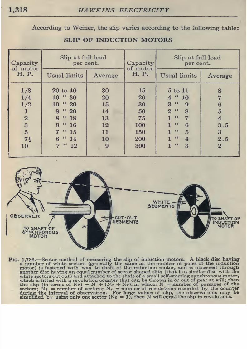
8/20/2019 electrical guide 5.pdf
http://slidepdf.com/reader/full/electrical-guide-5pdf 64/343
1,318
HAWKINS ELECTRICITY
According
to
Weiner,
the
slip
varies according
to
the
following
table:
SLIP
OF INDUCTION MOTORS
Capacity
of
motor
H. P.
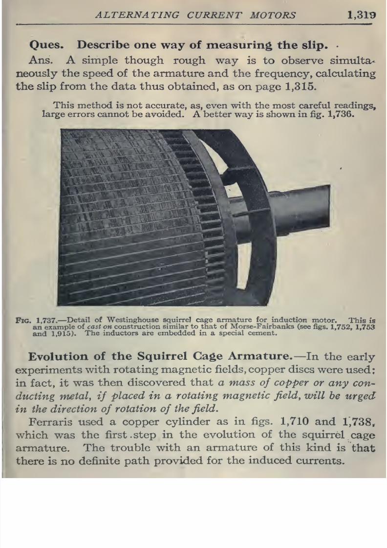
8/20/2019 electrical guide 5.pdf
http://slidepdf.com/reader/full/electrical-guide-5pdf 65/343
ALTERNATING
CURRENT
MOTORS
1,31^
Oues.
Describe
one
way of
measuring
the slip.
Ans. A
simple though
rough
way
is
to
observe
simulta-
neously
the
speed of
the armature
and the
frequency,
calctdating
the
slip
from
the
data
thus
obtained, as
on
page
1,315.
This
method
is not accurate,
as,
even
with
the most
careful
readings,
large errors cannot
be
avoided.
A
better
way
is
shown
in
fig. 1,736.
Fig.
1,737.
—
Detail of Westinghouse
squirrel
cage
armature
for
induction
motor.
This is
an
example
of
cast
on construction
similar
to
that
of
Morse-Fairbanks
(see
figs.
1,752, 1,753
and
1,913).
The
inductors
are
embedded
in
a
special
cement.
Evolution
of the
Squirrel
Cage
Armature.—
In
the
early
experiments
with rotating
magnetic
fields,
copper
discs
were
used;
in
fact,
it
was
then discovered
that
a
mass
of
copper
or
any
con-
ducting
metal,
if
placed
in a
rotating
magnetic
field,
will
be urged
in
the
direction
of
rotation
of
the
field.
Ferraris
used
a copper
cylinder
as in
figs.
1,710
and
1,738,
which
was
the
first.
step
in
the
evolution
of
the
squirrel
cage
armature.
The
trouble
with an
armature of this
kind
is
that
there is
no
definite
path provided
for
the induced
currents.
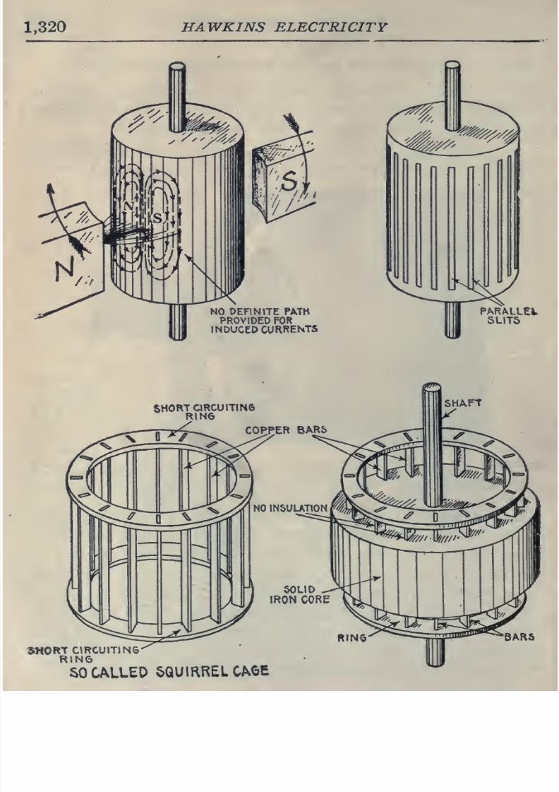
8/20/2019 electrical guide 5.pdf
http://slidepdf.com/reader/full/electrical-guide-5pdf 66/343
1,320
HAWKINS
ELECTRICITY
NO
DEFINITE
PATH
PROVIDED
FOR
INDUCED CURRENTS
SHORT
CIRCUITIN6
RIN6
BARS
SHORTGRCUmNG
RING
SO CALLED
SQUIRREL
CAOE
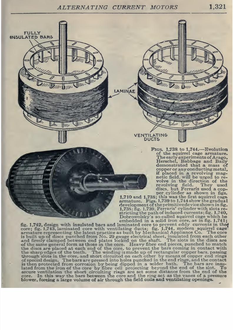
8/20/2019 electrical guide 5.pdf
http://slidepdf.com/reader/full/electrical-guide-5pdf 67/343
ALTERNATING
CURRENT MOTORS
1,321
Pigs.
1,738
to
1,744.
—
Evolution
of the
squirrel
cage
armature.
The
early
experiments
of
Arago,
Herschel, Babbage
and Baily
demonstrated that
a
mass of
copper
orany
conducting
metal,
if placed
in a
revolving
mag-
netic field, will be
urged to
re-
volve
in
the direction
of the
revolving field.
^
They
used
discs, but Ferraris
used
a cop-
per
cylinder
as shown
in figs.
,710
and
1,738;
this
was
the
first
squirrel
cagt,
armature.
Figs.
1,739
to
1,744
show
the
gradual
development
of
the
primitive
device
shown
in
fig.
1,738:
fig.
1,739.
Ferraris' cylinder with
slots
re-
stricting the
path
of
induced currents
;
fig.
1 ,740,
Dobrowolsky's so
called squirrel cage which
he
embedded
in a
solid
iron core,
as in fig.
1,741;
fig.
1,742,
design
with
insulated bars and
laminated
core
to
prevent
eddy currents
in
the^
core; fig.
1,743,
laminated
core
with
ventilating ducts;
fig.
1,744,
modern
squirrel
cage
armature
representing the
latest practice
as
built by
Mechanical
Appliance
Co. The
core
is
built
up
of
discs punched
from
No.
29
gauge
electrical
sheet,
insulated
from
each other
and
firmly
clamped
between
end
plates locked
on the
shaft.
The
slots
in
the
discs are
of
the same
general form
as
those
m
the core.
Heavy
fibre end
pieces,
punched
to
match
the discs
are placed at each
end of the
core, to
prevent
the
bars coming in
contact
with
the
sharp
edges
of
the
teeth.
The
winding
is
made
up
of
rectangular
copper
bars,
passing
through
slots
in
the
core,
and short circuited on
each
other
by
means
of
copper end
rings
of
special
design.
The
bars are
pressed
into holes
punched
in
the end rings,
and
the contact
is
tnen protected from
corrosion by
being
dipped
in
a
solder
bath.
The bars are
insu-
lated
from
the iron
of
the core
by
fibre
cell
projecting
beyond
the end of the
slot.
To
secure ventilation the
short
circuiting
rings
are
set
some
distance from
the
end
of
the
core. In this way the bars between the
core
and
the
ring
act as the vanes
of a pressure
blower,
forcing
a
large volume
of
air through
the
field
coila and
ventilating
openings.
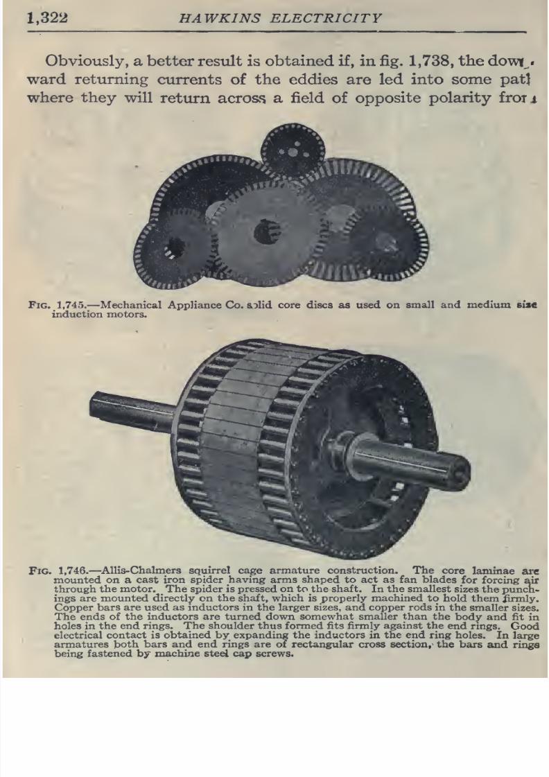
8/20/2019 electrical guide 5.pdf
http://slidepdf.com/reader/full/electrical-guide-5pdf 68/343
1,322
HAWKINS ELECTRICITY
Obviously,
a
better
result is
obtained
if,
in
fig.
1,738,
the
do\vi^«
ward
returning
currents
of
the
eddies
are led
into
some
pat^
where
they
will
return
acrosf>
a
field
of
opposite
polarity
froii
Fig. 1,745.—
Mechanical
Appliance Co.
solid
core
discs
as
used
on
small
and medium
sise
induction
motors.
Fig.
1,746.—
^AUIs-Chalmers
squirrel cage armature
construction.
The
core
laminae
are
mounted
on a
cast iron spider having
arms
shaped
to act as
fan blades
for
forcing
air
through
the
motor.
The
spider
is
pressed
on
to
the
shaft.
In
the
smallest
sizes
the
punct-
ings
are
mounted directly on
the
shaft,
which
is
properly machined
to
hold them
iirmly.
Copper
bars
are
used
as
inductors
in the
larger sizes, and
copper rods
in the
smaller
sizes.
The
ends
of
the
inductors are turned down somewhat
smaller
than
the
body
and fit
in
holes
in
the end
rings. The
shoulder
thus formed fits firmly
against
the
end rings.
Good
electrical
contact
is obtained by
expanding
the
inductors
in
the
end
ring
holes.
In
large
armatures
both
bars and
end
rings
are of
rectangular cross section,
the
bars
and rings
being
fastened
by machine steel cap screws.
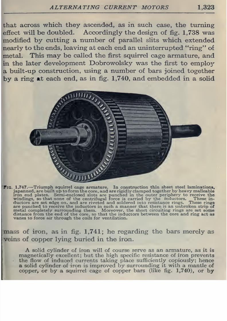
8/20/2019 electrical guide 5.pdf
http://slidepdf.com/reader/full/electrical-guide-5pdf 69/343
ALTERNATING
CURRENT
MOTORS
1.323
that
across
which
they
ascended, as in such
case, the
turning
ffect
will be
doubled. Accordingly
the
design of
fig.
1,738
was
by
cutting
a
number of parallel
slits
which extended
to
the
ends,
leaving
at
each
end
an
uninterrupted
ring
of
This
may
be
called the first
squirrel
cage
armature,
and
n
the
later
development
Dobrowolsky
was
the
first
to employ'
a
built-up
construction,
using a number
of bars joined
together
by
a
ring at
each
end,
as
in
fig.
1,740,
and
embedded in
a solid
Pig.
1,747.
—
Triumph squirrel
cage
armature.
In construction
thin
sheet steel
laminations,
japanned, are built
up
to
form the
core,
and are rigidly
clamped
together
by
heavy
malleable
iron
end
plates.
Semi-enclosed
slots
are
punched
in
the outer
periphery
to receive
the
windings,
so
that
none
of the
centrifugal
force
is
carried
by
the
inductors.
These
in-
ductors are
set
edge on, and are
riveted and
soldered into
resistance
rings.
These
rings
are punched to
receive
the
inductors
in
such a
manner that
there is an unbroken
strip
of
metal completely surrounding them. Moreover, the short
circuiting
rings
are
set
some
distance from
the
end
of
the core, so that the
inductors between
the core and
ring
act
as
vanes to force air through
the coils
for ventilation.
mass
of
iron,
as
in
fig.
1,741;
he
regarding
the bars
merely
as
veins
of copper
lying
buried
in
the iron.
A
solid
cylinder
of
iron
will
of
course
serve
as an
armature,
as
it
is
magnetically
excellent; but the
high specific
resistance of
iron
prevents
the flow
of
induced
currents
taking
place
sufficiently
copiously;
hence
a
solid
cylinder
of
iron is
improved by
surrounding
it
with a
mantle
of
copper, or
by a
squirrel
cage
of
copper
bars
(like fig.
1,740),
or
by
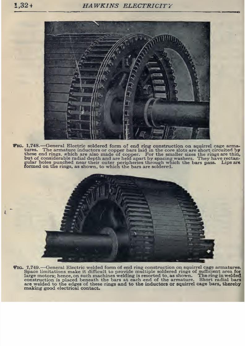
8/20/2019 electrical guide 5.pdf
http://slidepdf.com/reader/full/electrical-guide-5pdf 70/343
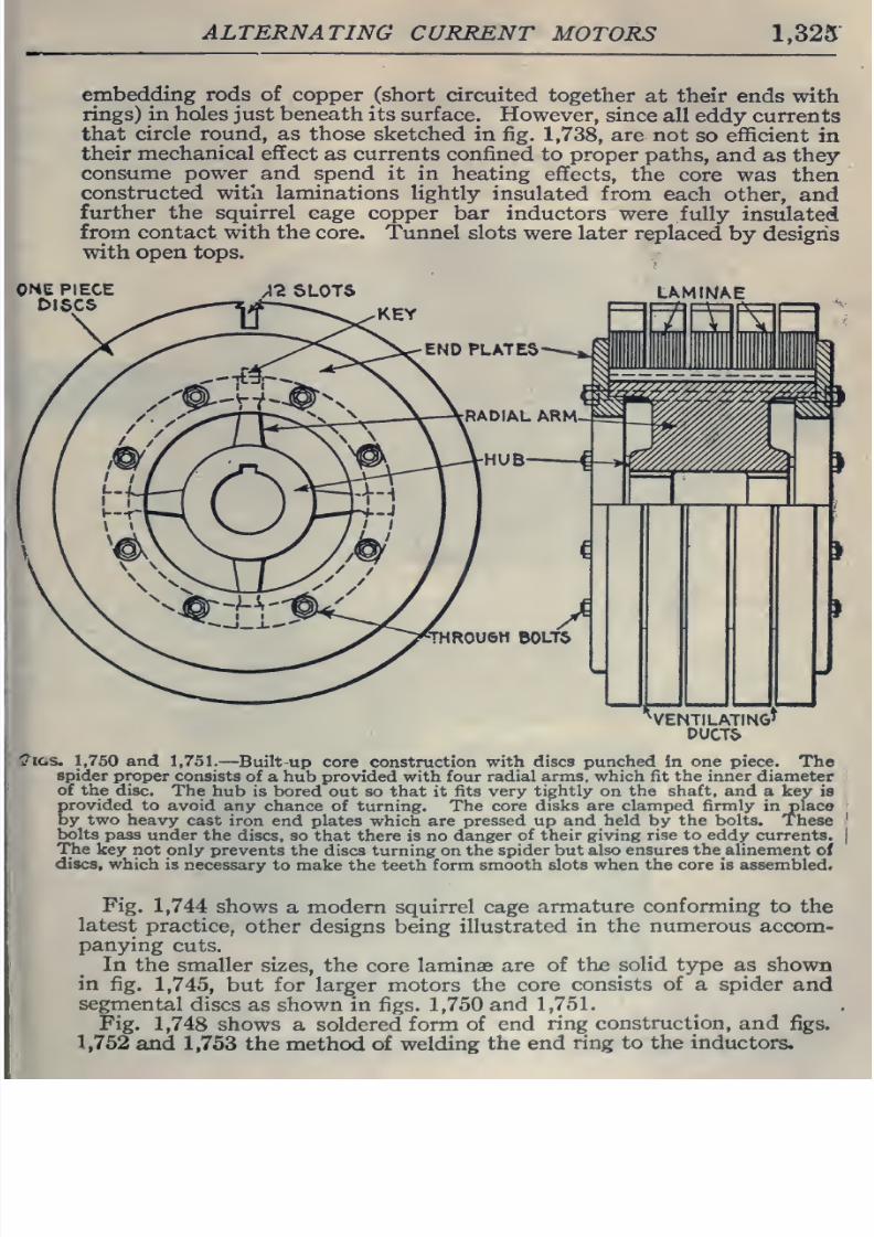
8/20/2019 electrical guide 5.pdf
http://slidepdf.com/reader/full/electrical-guide-5pdf 71/343
ALTERNATING
CURRENT
MOTORS
1,325
embedding rods of copper
(short circuited
together
at
their
ends
with
rings)
in holes
just
beneath
its surface.
However,
since
all
eddy
currents
that
circle
round,
as
those
sketched
in
fig.
1,738,
are
not
so
efficient
in
their
mechanical
effect
as
currents confined
to proper
paths,
and
as
they
consume power and
spend
it
in
heating
effects,
the
core
was then
constructed
with
laminations
lightly
insulated
from
each
other,
and
further
the
squirrel
cage copper
bar inductors
were fully
insulated
from contact
with the
core.
Tunnel
slots
were later
replaced by designs
with
open tops.
/I2
SLOTS
UMfNAE
VENTILATING^
DUCT&
?IGS.
1,750
and
1,751.
—
Built
up
core
construction
with
discs
punched in
one piece.
The
spider
proper consists
of a
hub
provided with
four
radial
arms,
which
fit
the inner
diameter
of the
disc.
The
hub
is
bored
out so that
it
fits very
tightly
on
the
shaft, and
a kev
is
Erovided
to
avoid
any chance
of turning. The
core
disks are clamped firmly
in place
y
two
heavy
cast iron
end plates
which
are pressed up
and held
by
the
bolts.
These
bolts
pass
under the
discs, so that
there
is
no
danger
of their giving
rise
to eddy currents.
The
key
not
only
prevents
the
discs turning on the
spider but
also
ensures the alinement
of
discs,
which
is
necessary
to make the
teeth
form
smooth slots
when
the
core is
assembled.
Fig.
1,744
shows
a
modern squirrel
cage
armature
conforming
to the
latest
practice,
other
designs
being
illustrated
in the numerous
accom-
panying
cuts.
In the
smaller
sizes, the
core
laminae are
of
the
solid type
as
shown
in
fig.
1,745,
but for
larger motors
the
core
consists of
a
spider
and
segmental
discs
as
shown in
figs.
1,750
and
1,751.
Fig.
1,748
shows
a
soldered
form
of
end
ring
construction,
and
figs.
1,752
and
1,753
the
method of
welding
the
end
ring
to the inductors.
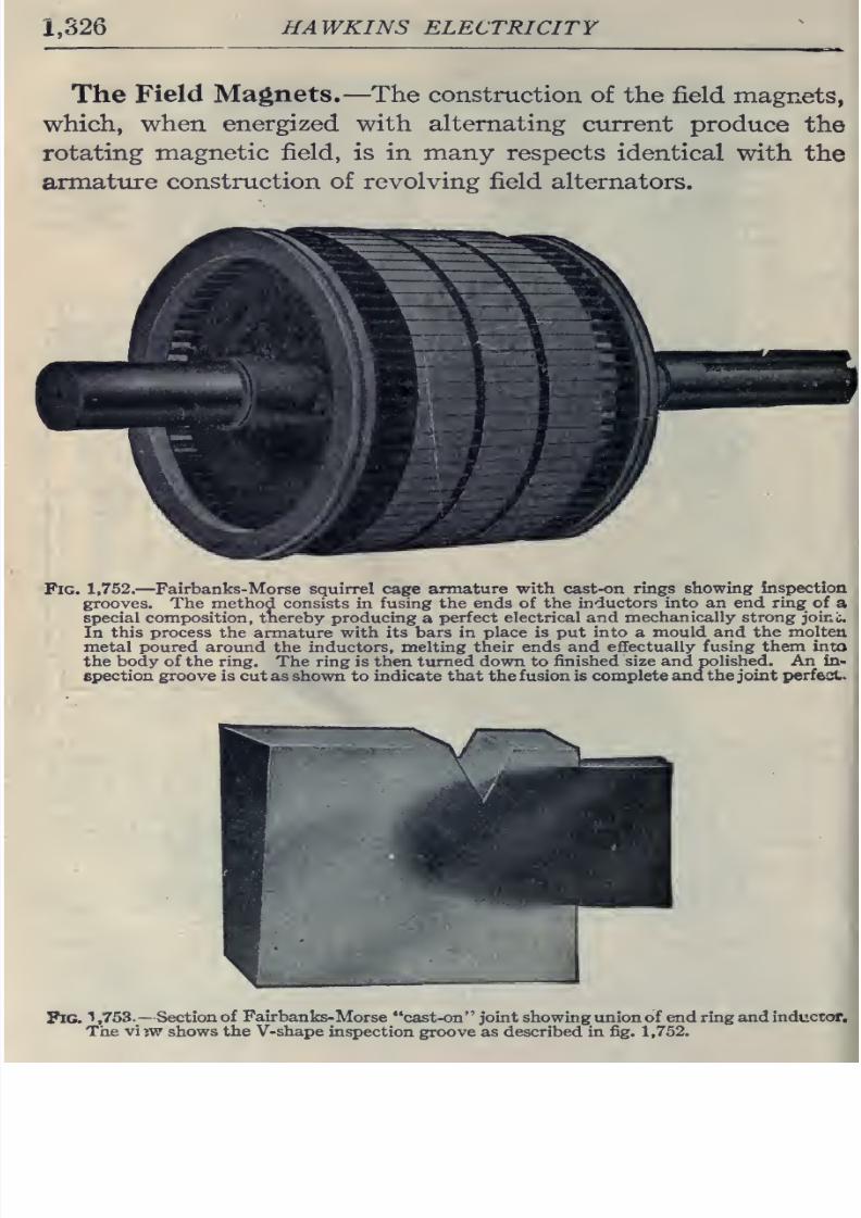
8/20/2019 electrical guide 5.pdf
http://slidepdf.com/reader/full/electrical-guide-5pdf 72/343
1,326
HAWKINS
ELECTRICITY
The
Field
Magnets.—The construction
of
the
field
magnets,
which,
when
energized with alternating
current
produce
the
rotating
magnetic
field, is
in
many
respects
identical
with
the
armature
construction
of
revolving
field
alternators.
Fig.
1,752.
—
Fairbanks-Morse squirrel
cage
armature with
cast-on
rings
showing
inspection
grooves. The method consists in
fusing
the
ends
of
the
inductors
into
an
end ring of
a
special
composition,
tnereby
producing
a
perfect
electrical
and mechanically strong joini.
In this
process
the armature with its
bars in
place
is put into a
mould
and the molten
metal
poured
around
the
inductors, melting
their ends and effectually
fusing
them into
the
body of the ring.
The
ring is then
turned
down to
finished
size
and
polished.
An
in-
epection
groove is
cut
as shown
to
indicate that the
fusion
is
complete
and
the
joint
perfect.
Fig.
1
,753.
—
Section
of Fairbanks-
Morse cast-on joint showing union
of end
ring
and
inductor.
The
vi
?w
shows
the V-shape
inspection
groove
as
described
in fig. 1,752.
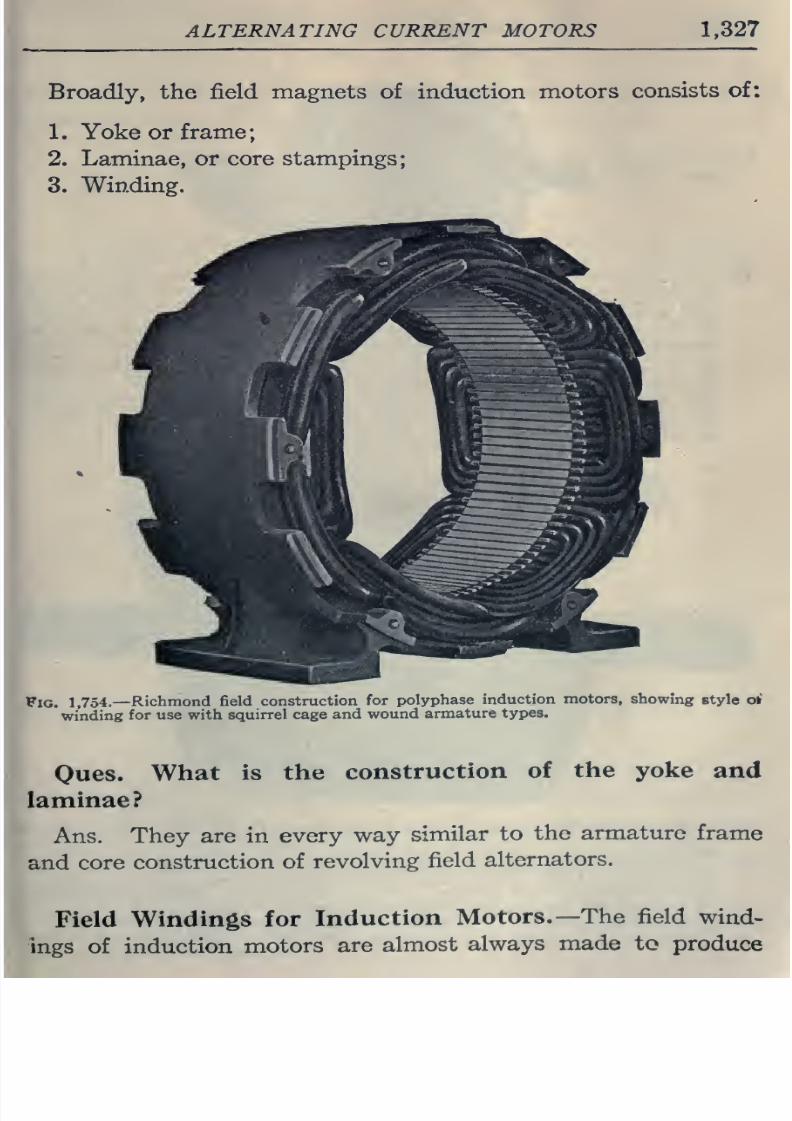
8/20/2019 electrical guide 5.pdf
http://slidepdf.com/reader/full/electrical-guide-5pdf 73/343
ALTERNATING CURRENT MOTORS 1,327
Broadly,
the
field
magnets
of induction
motors
consists
of:
1.
Yoke
or
frame;
2.
Laminae,
or
core stampings;
3. Winding.
Fig.
1.754.
—Richmond
field
construction
for
polyphase
induction
motors,
showing
style
<rf
winding
for use
with
squirrel
cage and
wound
armature
types.
Oues.
What is
the
construction
of
the yoke
and
laminae?
Ans.
They are
in
every
way
similar
to
the
armature
frame
and
core
construction
of
revolving
field
alternators.
Field
Windings for
Induction
Motors.—
The field
wind-
ings
of
induction
motors
are
almost
always
made
to
produce
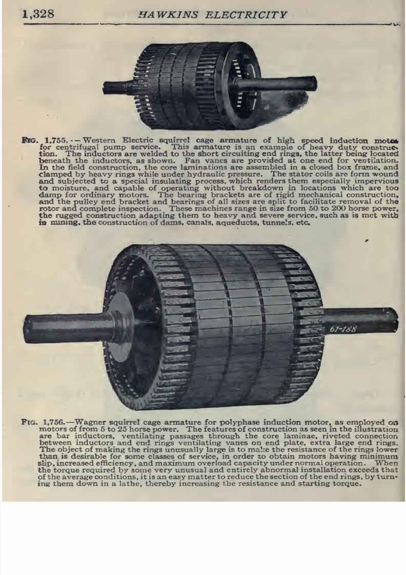
8/20/2019 electrical guide 5.pdf
http://slidepdf.com/reader/full/electrical-guide-5pdf 74/343
1,328
HAWKINS
ELECTRICITY
.
1,755.
—
Western
Electric squirrel cage
armature
of
high speed
induction
motOfr
for
centrifugal
pump
service.
This armature is
an
examjjle
of
heavy
dutjr
construe*
tion.
The
inductors
are
welded
to
the
short
circuiting
end
rings,
the latter being located
beneath
the inductors,
as
shown. Fan
vanes
are
provided
at
one
end for
ventilation.
In
the
field
construction, the core
laminations are
assembled
in a
closed
box
frame, and
clamped
by
heavy
rings
while
under
hydraulic
pressure.
The
stator
coils
are
form
wound
and
subjected
to
a
special insulating
process,
which
renders
them especially
impervious
to
moisture,
and capable
of
operating
without
breakdown
in
locations
which
are
too
damp
for ordinary motors.
The
bearing
brackets
are
of
rigid mechanical
construction,
and
the
pulley end bracket
and
bearings
of all
sizes
are split to
facilitate removal of
the
rotor
and
complete
inspection.
These
machines range
in
size
from
50 to
200
horse
power,
the
rugged
construction
adapting
them
to
heavy and
severe service, such
as
is
met
with
in
mining,
the
construction
of
dams,
canals,
aqueducts,
tunnels, etc
Fig.
1,756.
—
Wagner
squirrel
cage
armature for
polyphase
induction motor, as
employed
oa
motors
of
from
5
to 25 horse
power.
The
features
of
construction as seen
in
the
illustration
are
bar inductors,
ventilating
passages
through
the core laminae,
riveted
connection
between inductors
and end
rings ventilating
vanes
on
end plate,
extra
large
end rings.
The
object
of
making the
rings unusually
large is
to
mal:e
the
resistance
of
the
rings
lower
than,
is desirable
for
some classes of
service,
in order
to
obtain motors
having minimum
slip , increased
efficiency
, and
maximum
overload
capacity
under
normal
operation
.
When
the torque
required
by
some very
unusual and
entirely
abnormal installation
exceeds that
of
the
average
conditions,
it is an easy
matter
to
reduce the section of the end rings,
by
turn-
ing them
down in
a
lathe, thereby
increasing
the
resistance
and
starting torque.
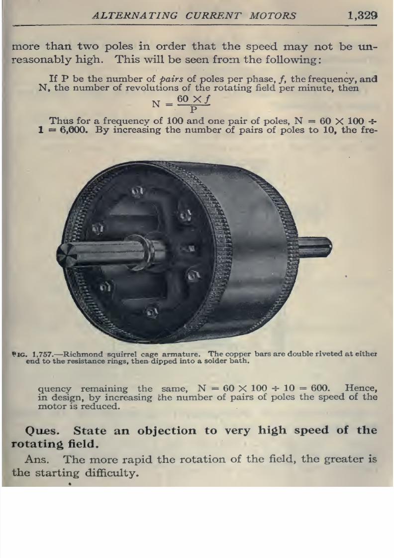
8/20/2019 electrical guide 5.pdf
http://slidepdf.com/reader/full/electrical-guide-5pdf 75/343
ALTERNATING
CURRENT
MOTORS
1,329
more
than two poles
in
order
that
the
speed
may
not
be un-
reasonably
high.
This will
be
seen from the following:
If
P
be
the
number
of pairs of poles per
phase,
/,
the frequency,
and
N,
the
number
of revolutions
of
the
rotating
field per
minute, then
N=52_><i
P
Thus
for
a
frequency
of
100
and
one
pair of
poles,
N
=
60
X
100
4-
1
=
6,000.
By
increasing
the number
of
pairs of poles to
10,
the fre-
?IG.
1,757.
—
Richmond
squirrel cage
armature.
The
copper bars are
double
riveted
at
eithei
end to
the
resistance rings, then
dipped
into
a
solder
bath.
quency
remaining
the
same,
N=60X100-^10
=
600.
Hence,
in design,
by
increasing
the
number
of
pairs
of poles the
speed
of
the
motor
is
reduced.
Ou^es.
State an
objection
to
very
high speed
of
the
rotating
field.
Ans.
The
more rapid the
rotation
of
the
field, the
greater
is
the
starting
diffioilty.
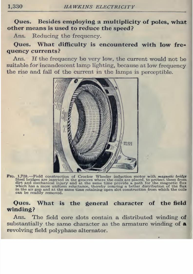
8/20/2019 electrical guide 5.pdf
http://slidepdf.com/reader/full/electrical-guide-5pdf 76/343
1,330
HAWKINS
ELECTRICITY
Oues.
Besides
employing
a
multiplicity
of
poles,
what
other
means
is used
to
reduce
the
speed
?
Ans.
Reducing the
frequency.
Ques. What
difficulty is
encountered
with
low
fre-
quency currents?
Ans. If
the
frequency
be very
low,
the
current
would
not be
suitable
for
incandescent
lamp
lighting,
because
at low
frequency
the
rise
and
fall of
the
current
in
the lamps
is
perceptible.
Pig.
1,768.—Field
construction
of
Crocker
Wheeler
induction
motor
with magnetic
bridge
Steel
bridges
are
inserted
in
the grooves where the
coils are
placed, to
protect
them
from
dirt
and
mechanical
injury and at
the
same time
provide a
path for the
magnetic flux
which
has
a
more
uniform
reluctance, thereby insuring
a
better distribution
of
the
flux
in
the
air
gap
and at
the
same time
retaining
open
slot
construction
from which
the
coils
can
be
readily
removed.
Ques.
What
is
the general
character
of
the
field
winding?
Ans.
The
field
core slots contain
a
distributed
winding
of
substantially
the
same
character
as
the
armature
winding
of
a
revolving
field
polyphase
alternator.
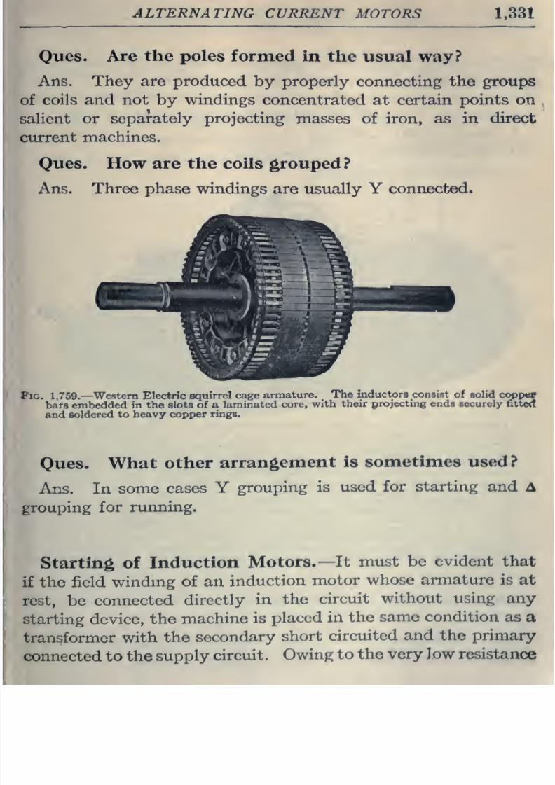
8/20/2019 electrical guide 5.pdf
http://slidepdf.com/reader/full/electrical-guide-5pdf 77/343
ALTERNATING
CURRENT
MOTORS
1,331
Oues.
Are
the
poles formed
in the
usual way?
Ans.
They
are
produced
by
properly
connecting
the groups
of
coils
and
not
by
windings
concentrated
at
certain
points
on
salient
or
separately
projecting
masses
of
iron,
as
in
direct
current
machines.
Ques.
How
are
the
coils grouped ?
Ans.
Three phase windings
are
usually Y
connected.
Pig.
1,769.—
Western Electric
squirrel cage
armature.
The
inductors consist
of
solid
cojppor
bars
embedded
in
the slots
of
a
laminated
core,
with
their
projecting
ends
securely
fittctt
and
soldered
to
heavy
copper
rings.
Ques.
What
other
arrangement
is
sometimes
used?
Ans.
In
some
cases
Y
grouping
is
used
for starting
and A
grouping
for running.
Starting of
Induction
Motors.—
It
must
be
evident that
if
the
field
winding of an
induction
motor
whose armature
is at
rest,
be
connected
directly
in
the
circuit
without
using
any
starting
device,
the
machine
is
placed
in
the
same
condition
as
a
transformer
with
the
secondary
short
circuited
and
the
primary
connected to
the
supply
circuit.
Owing
to
the very low resistance
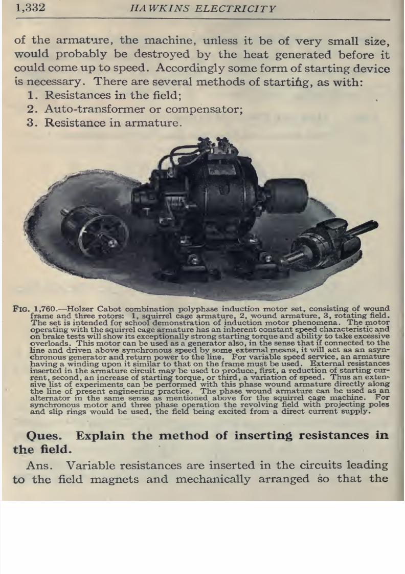
8/20/2019 electrical guide 5.pdf
http://slidepdf.com/reader/full/electrical-guide-5pdf 78/343
1,332
HAWKINS
ELECTRICITY
of
the armature, the
machine,
unless
it
be of very
small
size,
would
probably
be destroyed
by the
heat
generated
before
it
could come up
to
speed.
Accordingly
some
form
of starting
device
is
necessary.
There are
several
methods
of
starting,
as
with:
1.
Resistances
in the field;
2.
Auto-transformer
or
compensator;
3.
Resistance
in
armature.
Fig.
1,760.—Holzer
Cabot
combination
polyphase
induction
motor
set,
consisting
of wound
frame and three
rotors:
1,
squirrel cage armature,
2,
wound armature,
3,
rotating
field.
The
set is
intended
for school demonstration of
induction motor
phenomena. The
motor
operating with the
squirrel cage
armature
has an inherent
constant
speed
characteristic and
on
brake
tests
will show its
exceptionally strong
starting
torque
and
abihty to take
excessive
overloads.
This motor
can
be used as a generator
also, in
the
sense
that if
connected
to
the
line
and
driven
above
synchronous
speed
by
some
external
means,
it
will
act as
an
asyn-
chronous
generator and return
power
to
the
line.
For
variable speed
service,
an
armature
having
a
winding
upon
it similar to that on the
frame
must be
used.
External
resistances
inserted
in
the armature
circuit
may
be
used
to
produce, first, a
reduction
of
starting
cur-
rent,
second,
an
increase
of
starting
torque,
or third,
a
variation of
speed.
Thus
an
exten-
sive list of
experiments
can be
performed with this phase
wound armature
directly
along
the
line
of present
engineering
practice.
The
phase
wound armature
can be
used
as an
alternator in the same
sense
as
mentioned
above for
the
squirrel
cage
machine.
For
synchronous
motor
and
three
phase
operation
the
revolving
field with
projecting poles
and slip rings
would
be used,
the field
being
excited from a
direct
current
supply.
Oues.
Explain
the
method
of
inserting resistances
in
the
field.
Ans.
Variable
resistances
are inserted
in the
circuits
leading
to
the
field
magnets
and mechanically
arranged
so that
the
J
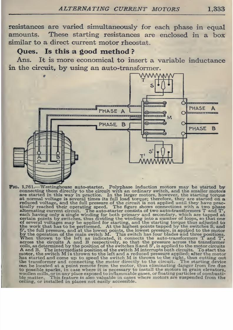
8/20/2019 electrical guide 5.pdf
http://slidepdf.com/reader/full/electrical-guide-5pdf 79/343
ALTERNATING
CURRENT
MOTORS
1,333
resistances
are
varied
simultaneously
for
each
phase
in equal
amounts.
These starting
resistances
are
enclosed
in a
box
similar to a
direct
current
motor
rheostat.
Oues.
Is
this
a
good
method
?
Ans.
It
is
more economical
to
insert
a
variable
inductance
in
the
circtut, by
using
an
auto-transformer.
9
Fig.
1,761.
—
Westinghouse
auto-starter.
Polyphase
induction
motors
may
be started
by
connecting them
directljr
to
the
circuit with an
ordinary
switch,
and the
smaller
motors
are started
in this way
in
practice.
In
the
larger motors, however, the starting
torque
at
normal voltage
is
several
times
its
full load
torque;
therefore,
they
are started
on
a
reduced
voltage,
and
the full
pressure
of
the circuit is not
applied
until they
have prac-
tically
reached
their
operating speed. The
figure
shows
connections with
a two
phase
alternating
current
circuit. The auto-starter
consists of
two
auto-transformers
T
and
T',
each
having
only
a
single
winding
for
both
primary
and
secondary,
which
are
tapped
at
certain
points
by
switches, thus
dividing
the
winding
into a
number of loops,
so
that
one
of
several
voltages
may
be
applied for
starting, and
the
starting
torque
thus
adjusted
to
the work
that
has
to be
performed.
At
the
highest points
tapped by the
switches
S, and
S', the full
pressure,
and
at
the
lowest
points,
the
lowest
pressure, is
applied to
the
motor
by
the
operation
of the
main switch
MT
This
switch
has
four
blades
and
threepositions.
When
thrown
to
the
left
as
indicated,
it
connects the
auto-transformers
T
and
T',
across the
circuits
A and
B
respectively,
so that
the pressure across
the
transformer
coils, as
determined
by
the
position
of
the
switches
Sand S
,
is applied
to the motor
circuits
A
and
B.
The
intermediate position of
the
switch
M
interrupts
both circuits.
To
start
tho
motor, the switch
M
is thrown
to
the
left and a
reduced pressure applied;
after the
motor
has
started
and
come
up
to
speed
the
switch
M
is
thrown
to the right,
thus cutting
out
the transformer
and
connecting the
motor
directly
to
the
circuit.
The starting
device
can
be
located
at
a
point remote from the
motor,
thus
eliminating
danger
from fire
due
to
possible
sparks,
in
case where it is
necessary to
install
the
motors
in grain
elevators,
woollen
mills,
or
in
any
place exposed to
inflammable
gases,
or
floating
particles
of
combusti-
ble
matter. This feature is also
valuable in
cases
where
motors are
suspended
from
the
ceiHng,
or
installed
in
places
not
easily
accessible.
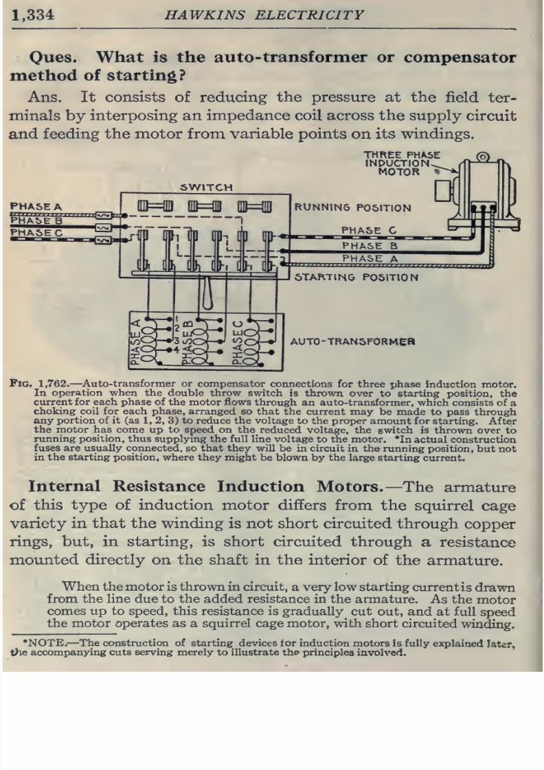
8/20/2019 electrical guide 5.pdf
http://slidepdf.com/reader/full/electrical-guide-5pdf 80/343
1,334
HAWKINS
ELECTRICITY
Oues.
What
is
the auto-
transformer
or
compensator
method
of
starting?
Ans. It
consists
of reducing
the pressure
at
the
field ter-
minals
by
interposing
an
impedance
coil
across
the
supply
circuit
and
feeding
the
motor from
variable
points
on
its windings.
PHASE
A
PHA5EB
PHASE
C
SWITCH
115=03
IU=i
]
HP
I
E
^
mi-;
m
iiJt
iij=i
I
l<Of-»4<oj-#
$OJ-«
.
I h
I
h
THREE PHASE
INDUCTION
MOTOR
RUNNING
POSITION
PHASE
C
PHASE
B
PHASE
A
STARTING
POSITION
AUTO-TRANSFORMER
Pig. 1,762.
—
Auto-transformer or
compensator
connections
for three
phase induction motor.
In
operation when the double
throw switch
is thrown
over
to
starting
position,
the
current
for
each
phase
of the
motor flows
through
an auto-transformer,
which consists
of
a
choking
coil for
each
phase,
arranged so
that
the
current
may be made
to pass
through
any
portion
of
it
(as
1,
2,
3)
to reduce the
voltage
to the proper amount for
starting. After
the
motor
has come
up to speed
on the
reduced
voltage,
the switch is thrown
over
to
running
position, thus
supplying the full
line voltage
to
the
motor.
*In actual construction
fuses are
usually
connected,
so
that they will
be in circuit
in
the running
position,
but not
in
the starting position,
where
they
might
be
blown by
the
large
starting
current.
Internal
Resistance
Induction
Motors.
—The
armature
of
this
type
of
induction
motor differs
from the
squirrel
cage
variety in that the winding
is
not
short
circuited
through
copper
rings,
but,
in
starting,
is short circuited
through
a
resistance
moimted
directly
on
the
shaft
in
the
interior
of the
armature.
When
the
motor
is
thrown
in
circuit,
a
very
low
starting
current
is
drawn
from
the line
due
to
the
added resistance
in
the armature.
As the
motor
comes
up
to speed, this resistance
is
gradually
cut out, and
at full
speed
the motor
operates
as a squirrel cage motor,
with
short circuited
winding.
*NOTE.—
The construction of starting devices
for
induction
motors is
fully
explained
later,
the
accompanying cuts
serving merely
to
illustrate the principles
involved.
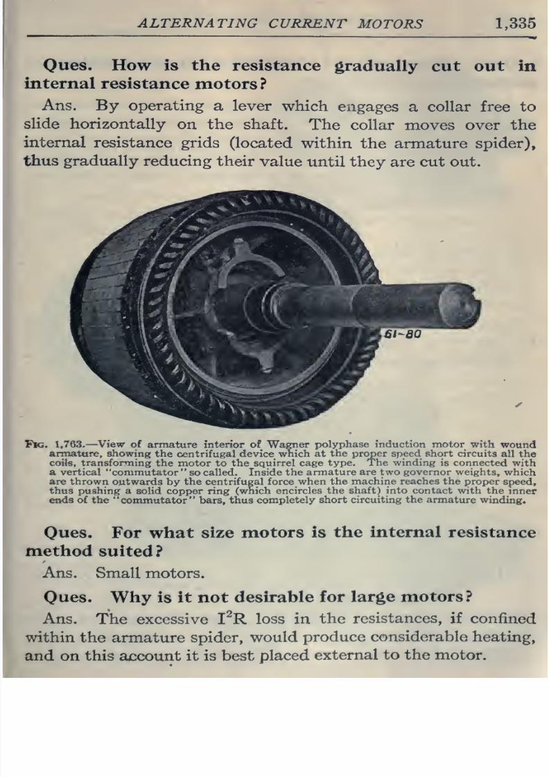
8/20/2019 electrical guide 5.pdf
http://slidepdf.com/reader/full/electrical-guide-5pdf 81/343
ALTERNATING
CURRENT
MOTORS
1,335
—
—__
WW
Oues.
How
is
the
resistance
gradually
cut
out
in
internal
resistance
motors?
Ans. By operating
a
lever
which
engages
a
collar free
to
slide
horizontally
on the shaft.
The collar
moves over
the
internal
resistance
grids
(located
within
the
armature spider),
thus gradually
reducing
their
value
until they
are
cut out.
Tk.
1,763-
—
View
of armature
interior of
Wagner
polyphase
induction motor
with
wound
armature, showing
the centrifugal device
which
at
the
proper speed short
circuits
all
the
coils,
transforming
the motor
to
the
squirrel cage
type.
The winding
is connected
with
a
vertical
commutator
so
called.
Inside
the
armature
are
two
governor
weights,
which
are
thrown
outwards
by
the centrifugal
force
when
the
machine reaches
the
proper
speed,
thus pushing a
solid
copper ring
(which encircles
the
shaft)
into contact with
the
inner
ends
of
the
commutator
bars,
thus
completely short
circuiting
the
armature
winding.
Oues.
For what
size
motors is
the
internal
resistance
method
suited?
Ans.
Small
motors.
Oues.
Why
is
it
not
desirable
for
large
motors
?
Ans.
The excessive
I^R
loss in
the
resistances,
if confined
within the
armature
spider,
would
produce
considerable
heating,
and
on
this
account
it is
best
placed
external
to the
motor.
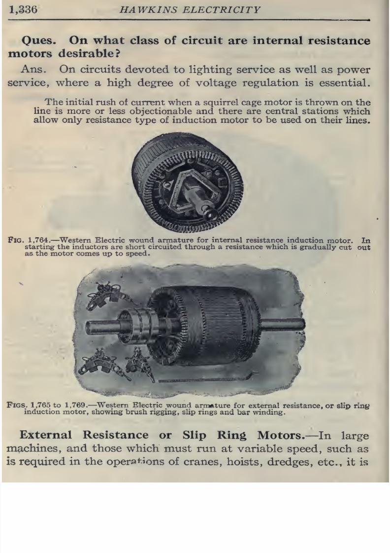
8/20/2019 electrical guide 5.pdf
http://slidepdf.com/reader/full/electrical-guide-5pdf 82/343
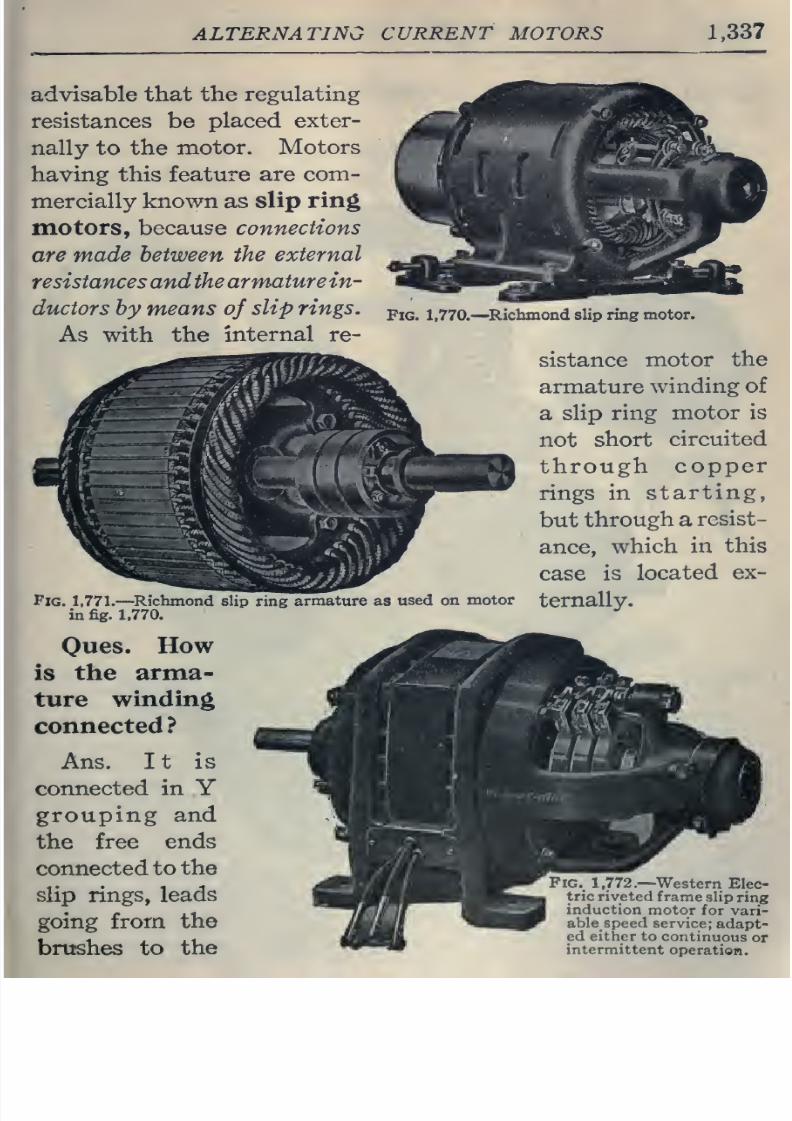
8/20/2019 electrical guide 5.pdf
http://slidepdf.com/reader/full/electrical-guide-5pdf 83/343
ALTERNATING
CURRENT
MOTORS
1,337
advisable
that
the
regulating
resistances be
placed
exter-
nally
to
the
motor.
Motors
having
this
feature
are
com-
mercially known as
slip
ring
motors,
because
connections
are
made
between the
external
resistancesand
the
armature in-
ductors
by
means
of
slip rings.
As
with
the
internal
re-
«^'.<^^
Pig. 1,771.—
Richmond
slip ring
armature
as
used
on
motor
in
fig.
1,770.
Oues.
How
is
the arma-
ture
winding
connected ?
Ans. It
is
connected
in
Y
grouping and
the
free
ends
connected
to the
slip
rings,
leads
going
from
the
brushes to
the
Fig.
1,770.—
^Richmond
slip
ring
motor.
sistance
motor
the
armature
winding of
a
slip
ring
motor
is
not
short
circuited
through
copper
rings
in
starting,
but
through a
resist-
ance,
which
in
this
case
is
located
ex-
ternally.
Pig.
1.772.—
Western
Elec-
tric riveted
frame
slip
ring
induction
motor
for
vari-
able
speed
service;
adapt-
ed
either
to
continuous
or
intermittent
operation.
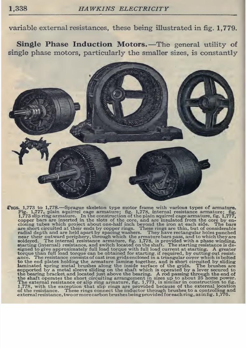
8/20/2019 electrical guide 5.pdf
http://slidepdf.com/reader/full/electrical-guide-5pdf 84/343
1.338
HAWKINS ELECTRICITY
variable
external
resistances,
these being illustrated
in
fig.
1,779.
Single
Phase
Induction Motors.—
The
general
utility of
single
phase
motors,
particularly
the
smaller
sizes,
is
constantly
«^GS.
1,773
to
1,778.
—
Sprague
skeleton
type
motor frame with various
types
of
armature.
Fig.
1,777,
plain
squirrel
cage armature;
fig.
1,778,
internal resistance
armature;
fig.
1,773
slip ring
armature.
In
the
construction
of the plain
squirrel
cage
armature,
fig.
1,777,
copper
bars
are
inserted
in
the
slots
of
the
core,
and
are
insulated from
the
core
by en-
closing
tubes
which
project
about
one-half
inch
beyond
the iron at each side.
The
bars
are
short
circuited at their
ends
by
copper
rings.
These
rings are thin, but of
considerable
radial
depth
and are
held apart
by
spacing
washers.
They
have
rectangular
holes
punched
near theu
outward
periphery
,
through which the
armature
bars pass,
and
to
which
they
are
soldered.
The internal
resistance armature, fig.
1,778,
is
provided with a phase
winding,
starting
(internal)
resistance, and switch located
on
the
shaft. The
starting
resistance
is
de-
signed
to give
approximately
full load
torque
with full
load
current
at
starting.
A greater
torque
than full load
torque
can
be obtained for starting,
if required, by
cutting
out
resist-
ance.
The resistance
consists
of cast iron grids enclosed
in
a triangular
cover which is
bolted
to the
end
plates
holding the
armature
laminae together,
and
is short circuited
by
sliding
laminated
spring
metal
brushes along
the
inside
surface
of
the
grids.
The
brushes
are
supported
by
a metal sleeve
sliding
on
the shaft
which
is operated
by
a lever
secured
to
the bearing bracket and
located
just
above
the bearing.
A rod passing through
the
end
of
the
shaft
operates
the short
circuiting
arrangement
in sizes
up
to
about
25
horse power.
The external
resistance
or
slip
ring
armature,
fig.
1,773,
is
similar
in construction to fig.
1,778,
with the exception
that slip
rings are provided
because
of
the
external
location
of
the
resistance.
These rings connect
the
inductor through
brushes
to
a
controlling and
external
resistance ,two
or
more
carbon
brushes
beingprovided
foreach
ring,
as
in fig
.
1
,776
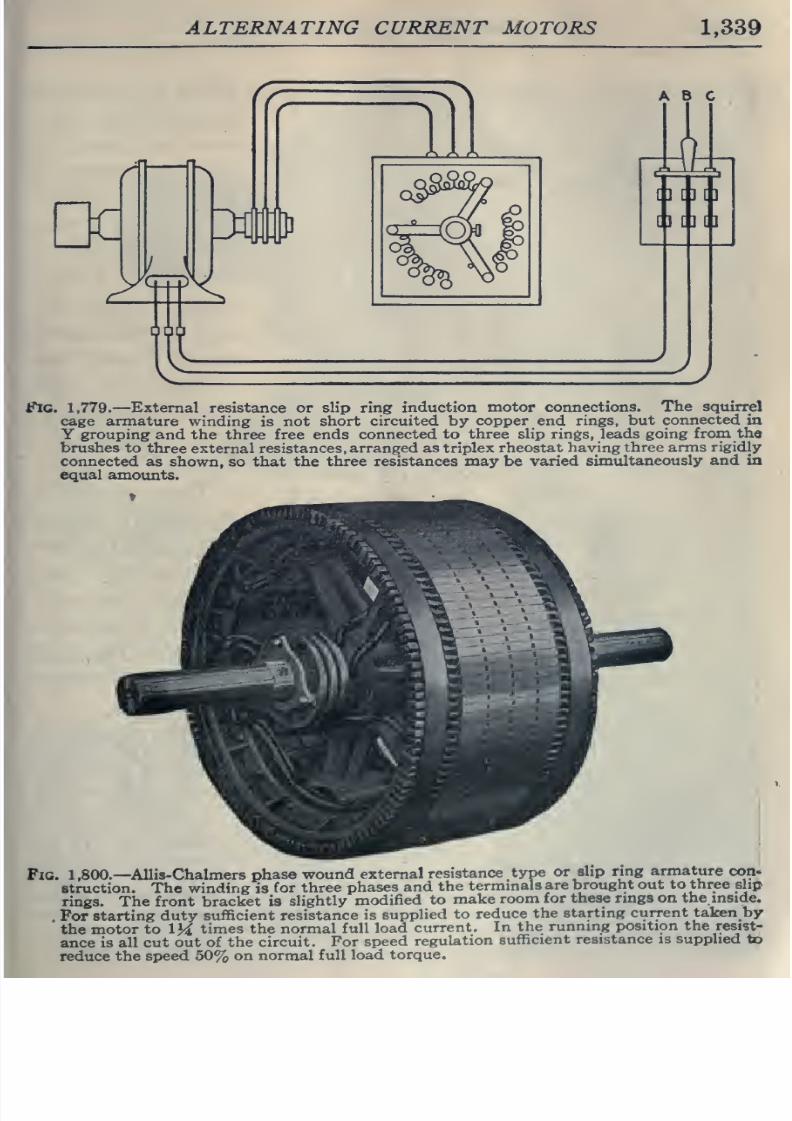
8/20/2019 electrical guide 5.pdf
http://slidepdf.com/reader/full/electrical-guide-5pdf 85/343
ALTERNATING
CURRENT
MOTORS
1,339
r
He
^
kLSj
3#
1
ABC
Fig.
1,779.
—External
resistance
or
slip
ring
induction
motor connections.
The squirrel
cage
armature
winding
is
not
short
circuited
by
copper
end rings,
but
connected in
Y
grouping
and
the
three free
ends
connected
to
three
slip rings,
leads
going
from
the
brushes
to
three
external
resistances,
arranged
as
triplex
rheostat
having
three
arms
rigidly
connected
as
shown,
so that
the
three resistances may
be varied
simultaneously
and
in
equal
amounts.
Fig.
1,800.—
Allis-Chalmers
phase
wound
external
resistance
type
or
slip ring
armature
com
struction.
The winding
is
for
three
phases and
the
terminals
are
brought
out
to three
slip
rings.
The
front
bracket is
slightly
modified
to
make
room
for
these
rings
on
the
inside.
For
starting
duty
sufficient
resistance is
supplied
to
reduce
the
starting
current
taken by
the
motor
to
IM
times the
normal
full
load
current.
In
the
running
position the
resist-
ance is
all
cut
out of the circuit.
For
speed
regulation
sufficient
resistance is supplied to
reduce
the
speed
50%
on
normal
full
load
torque.
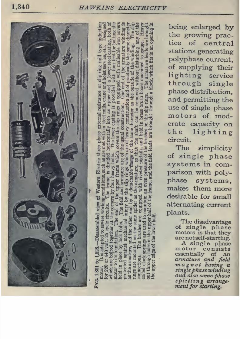
8/20/2019 electrical guide 5.pdf
http://slidepdf.com/reader/full/electrical-guide-5pdf 86/343
1,340
HAWKINS
ELECTRICITY
i^:S^^^^
arils'
•6'-'
boo
o >^
c
•
(u
a
CXI
o
c
u
>
S.
c
c
oj
>
•
„;
'^
.^^.aa.a
.|»gg-ng
llfL^liJi^fl
a+^.2
S
>
='o
S:S
c^
w
.Si
55:2
of
«;
o2
%B3
art
+j
E:3«go«
oo^^.:g3
2.S-2:^?i
JO;ii
O
0.0
o
^^•S
(U
rt
S
3
wJ3
W
being
enlarged
by
the
growing
prac-
tice
of
central
stations
generating
polyphase
current,
of
supplying
their
lighting
service
through
single
phase
distribution,
and
permitting
the
use
of
single
phase
motors
of
mod-
erate
capacity
on
the
lighting
circuit.
The
simplicity
of
single
phase
systems
in
com-
parison
with
poly-
phase
systems,
makes
them
more
desirable
for
small
alternating current
plants.
The
disadvantage
of
single
phase
motors
is
that
they
are
not
self
-starting.
A
single
phase
motor
consists
essentially
of
an
armature
and
field
magnet
having
a
single
phase
winding
and
also
some
phase
splitting
arrange
mentfor
starting.
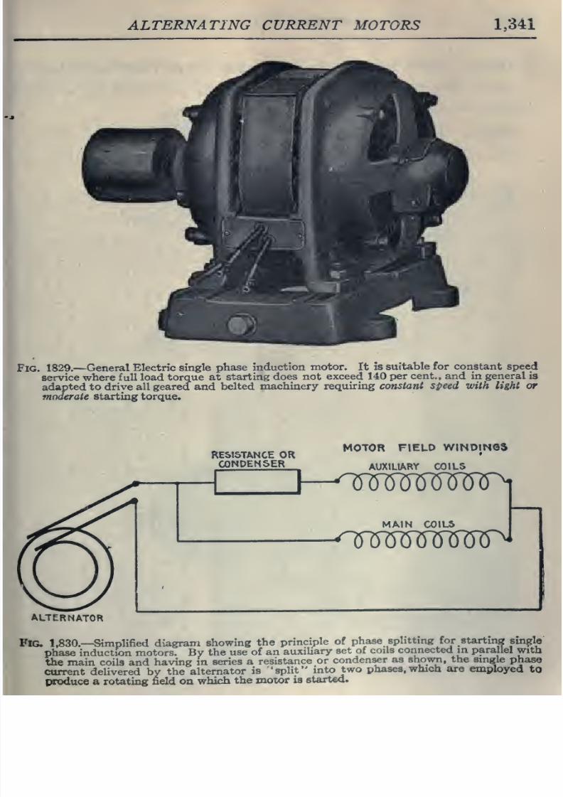
8/20/2019 electrical guide 5.pdf
http://slidepdf.com/reader/full/electrical-guide-5pdf 87/343
ALTERNATING
CURRENT
MOTORS
1,341
Fig.
1829.
—
General
Electric
single
phase
induction
motor.
It
is
suitable
for
constant
speed
service where full
load
torque at
starting
does
not
exceed
140
per
cent., and
in
general
is
adapted to
drive
all
geared and
belted
machinery
requiring
constant speed with light or
moderate starting
torque.
RESISTANCE
OR
CONDENSER
MOTOR
FIELD
WINOINOS
_
AUXILIARY
COILS
MAIN
COILS
'l^MWSW^
ALTERNATOR
Fig.
1,830.—
Simplified
diagram
showing
the
pnnciple
of
phase
splittmg
forstartmg
smple
phase
induction
motors.
By
the
use
of
an
auxiliary
set
of
coils
connected
in
parallel
with
the
main coils
and
having in
series
a
resistance
or
condenser
as
shown, the single
phase
current delivered
by
the
alternator
is
'split
into
two
phases,
which
are
employed
to
produce a
routing
field
on
which
the
motor
is
started.
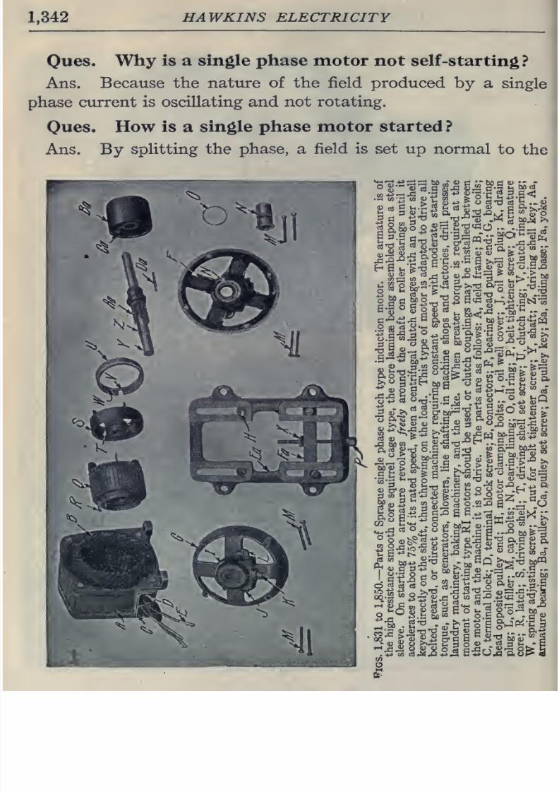
8/20/2019 electrical guide 5.pdf
http://slidepdf.com/reader/full/electrical-guide-5pdf 88/343
1,342
HAWKINS ELECTRICITY
Oues.
Why
is
a
single
phase
motor
not
self
-starting?
Ans.
Because
the
nature of
the
field produced
by
a
single
phase
current
is
oscillating
and
not
rotating.
Oues.
How
is
a
single phase motor started
?
Ans. By
splitting the
phase,
a
field is set
up
normal
to
the
>
(J
rt'd
oJ h
5
a
'
-e-a
^'O
cSTJ
M5
u-^
J^^
n.o
S
•-
2
«
«
^^
•2^13
B>.^r^Mri
3
<u
0)
5
C'C.
S
52^-^8
A
S
'u^SI^-S'^
^-^
fe'S S -S
S2
ft
ri-3
a;
S'rt'O
Sirii
4)
c
n
'-'
.,
a+j
C/)
I
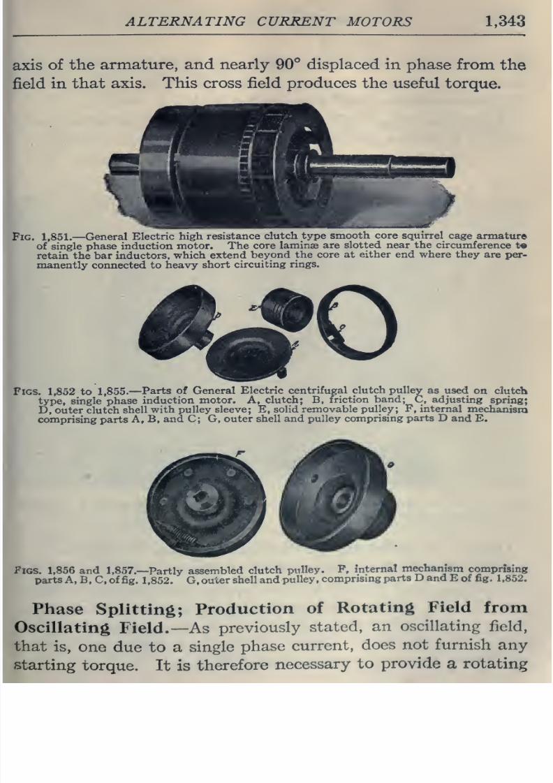
8/20/2019 electrical guide 5.pdf
http://slidepdf.com/reader/full/electrical-guide-5pdf 89/343
ALTERNATING
CURRENT
MOTORS
1,343
axis
of
the
armature,
and
nearly
90°
displaced
in phase
from
the
field
in
that
axis. This cross field
produces
the
useful
torque.
Fig.
1,851.
—
General
Electric
high
resistance
clutch
type
smooth
core
squirrel
cage
armature
of single
phase induction
motor.
The
core
laminae
are
slotted near the
circumference
t«
retain the
bar
inductors,
which
extend
beyond
the core
at
either
end
where
they are
per-
manently
connected
to
heavy
short
circuiting
rings.
Figs.
1,852
to
1,855.
—
Parts of
General
Electric centrifugal
clutch pulley
as used
on
clutch
type,
single
phase
induction
motor.
A,
clutch;
B,
friction
band;
C,
adjusting
spring;
D,
outer
clutch
shell
with
pulley sleeve; E,
solid
removable
pulley;
F,
internal
mechanism
comprising
parts
A,
B,
and C; G, outer
shell
and
pulley
comprising
parts
D
and
E.
Figs.
1.856
and
1,857.—
Partly
assembled
clutch
pulley.
P,
internal
mechanism
comprising
parts A, B, C, of
fig.
1,852.
G,
outer
shell
and
pulley,
comprismg
parts
D and
E
of
fig.
1,852.
Phase
Splitting;
Production
of
Rotating
Field
from
Oscillating
Field.—
As
previously
stated,
an
oscillating
field,
that
is,
one
due
to
a
single
phase
current,
does
not
furnish
any
starting
torque.
It is
therefore
necessary
to
provide
a rotating
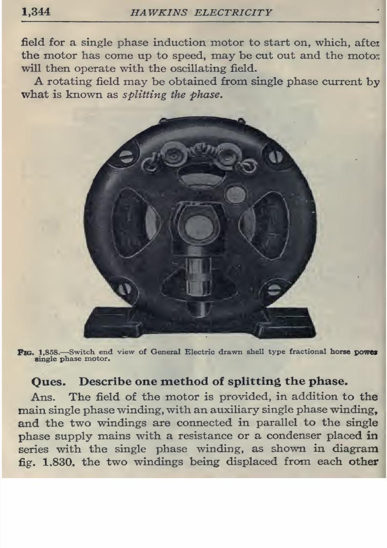
8/20/2019 electrical guide 5.pdf
http://slidepdf.com/reader/full/electrical-guide-5pdf 90/343
1,344
HAWKINS ELECTRICITY
field
for a single
phase
induction
motor
to
start
on,
which,
aftei
the
motor
has
come
up
to speed,
may
be
cut out
and
the
motoi:
will
then
operate
with
the
oscillating field.
A
rotating
field
may
be
obtained
from
single
phase
current
by
what
is
known
as
splitting
the
phase.
Fig.
1,858.
—
Switch
end
view
of General
Electric
drawn
shell
type
fractional
horse
powet
single
phase
motor.
Ques.
Describe
one
method
of
splitting
the
phase.
Ans.
The
field
of the
motor
is
provided, in
addition
to
the
main
single
phase
winding,
with
an
auxiliary
single
phase
winding,
and
the
two
windings
are
connected
in
parallel
to
the
single
phase
supply
mains with
a
resistance
or a
condenser
placed
in
series
with
the
single
phase
winding, as
shown
in
diagram
fig.
1.830.
the
two
windings
being
displaced
from
each
other
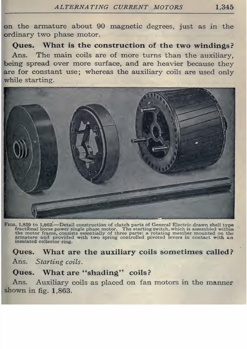
8/20/2019 electrical guide 5.pdf
http://slidepdf.com/reader/full/electrical-guide-5pdf 91/343
ALTERNATING
CURRENT
MOTORS
1,345
on
the
armature
about 90 magnetic
degrees,
just
as in
the
ordinary
two phase
motor.
Oues.
What
is
the
construction
of
the
two windings?
Ans.
The
main
coils are
of
more
turns
than
the auxihary,
being
spread over
more
surface,
and
are
heavier
because they
are
for
constant
use;
whereas
the auxihary
coils
are
used
only
while
starting.
Figs.
1,859
to
1,862.
—
Detail
construction
oi ciutcn
purls
ot
Cjcncriil
hicctnc
drawn
sheii
type
fractfonal
horse
power single phase motor. The
starting switch, which
is
assembled
within
the
motor
frame,
consists essentially
of
three parts:
a
rotating
member
mounted
on
the
armature
and
provided
with two
spring controlled pivoted
levers
in
contact
with
an
insulated
collector
ring.
Oues. What
are the
auxiliary
coils
sometimes
called?
Ans.
Starting
coils.
Oues.
What
are
**shading
coils?
Ans.
Auxiliary
coils
as
placed on
fan
motors
in
the
manner
shown
in
fig.
1,863.
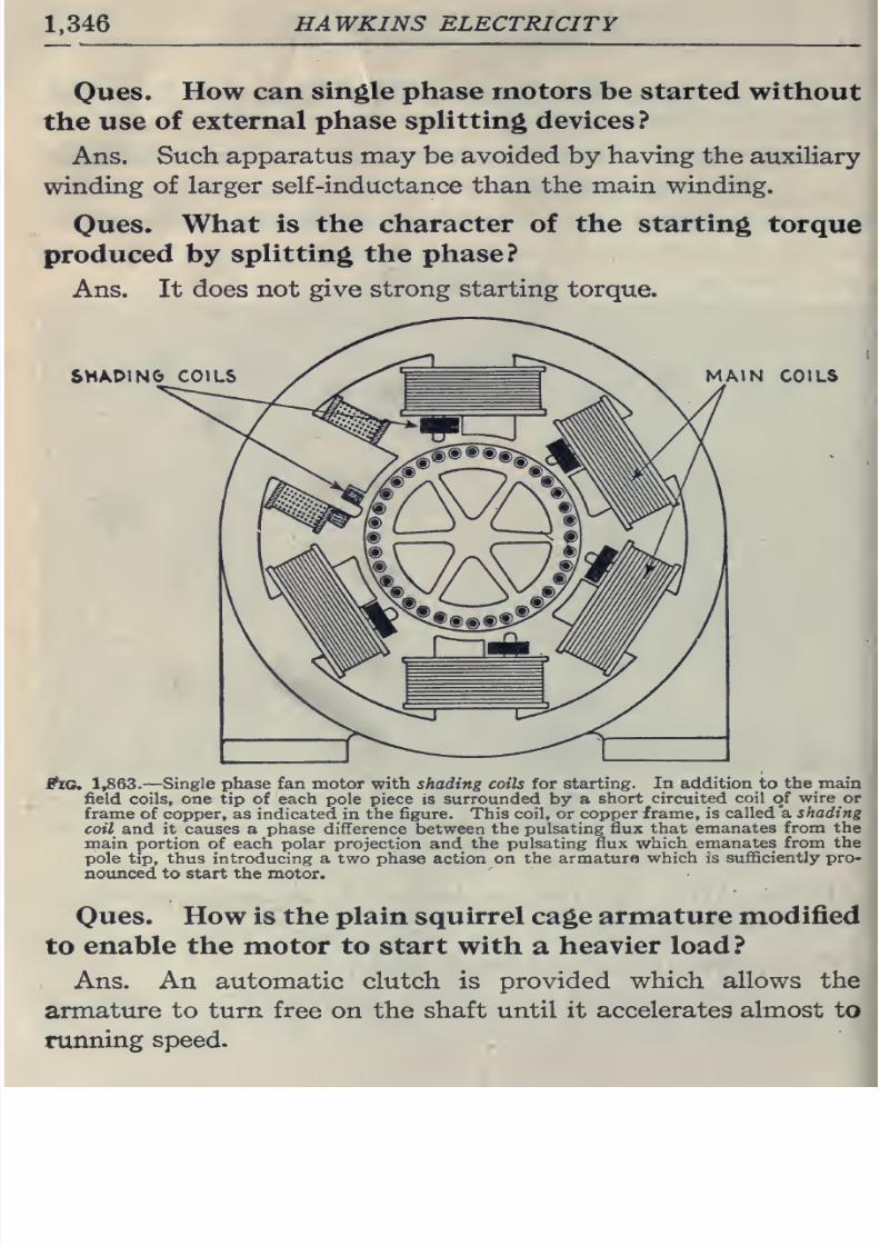
8/20/2019 electrical guide 5.pdf
http://slidepdf.com/reader/full/electrical-guide-5pdf 92/343
1.346
HAWKINS
ELECTRICITY
Ques.
How can
single
phase motors be
started without
the
use
of
external
phase
splitting
devices?
Ans.
Such apparatus
may
be
avoided by
having
the
auxiliary
winding
of
larger
self
-inductance
than
the
main
winding.
Ques. What
is
the
character
of
the
starting
torque
produced
by
splitting the phase?
Ans. It
does
not give
strong
starting
torque.
SM/kDIN&
COILS
MAIN
COILS
ftc.
1,863.
—
Single phase fan motor
with shading coils
for starting.
In addition
to
the main
field
coils, one
tip of each
pole piece
is surrounded
by a
short circuited
coil
of
wire
or
frame
of
copper,
as indicated
in
the figure. This coil, or
copper frame, is
called a
shading
coil and
it
causes a phase
difference between
the pulsating
flux that emanates
from
the
main
portion
of
each
polar
projection
and
the pulsating
flux
which
emanates from
the
pole tip, thus introducing
a
two
phase action
on the armaturo
which
is sufficiently pro-
notmced to
start the
motor.
Ques. How is the
plain squirrel
cage armature
modified
to
enable the
motor
to
start
with
a
heavier
load?
I
Ans. An automatic clutch
is
provided
which allows the
armature
to turn free
on
the shaft
until
it
accelerates almost to
running
speed.
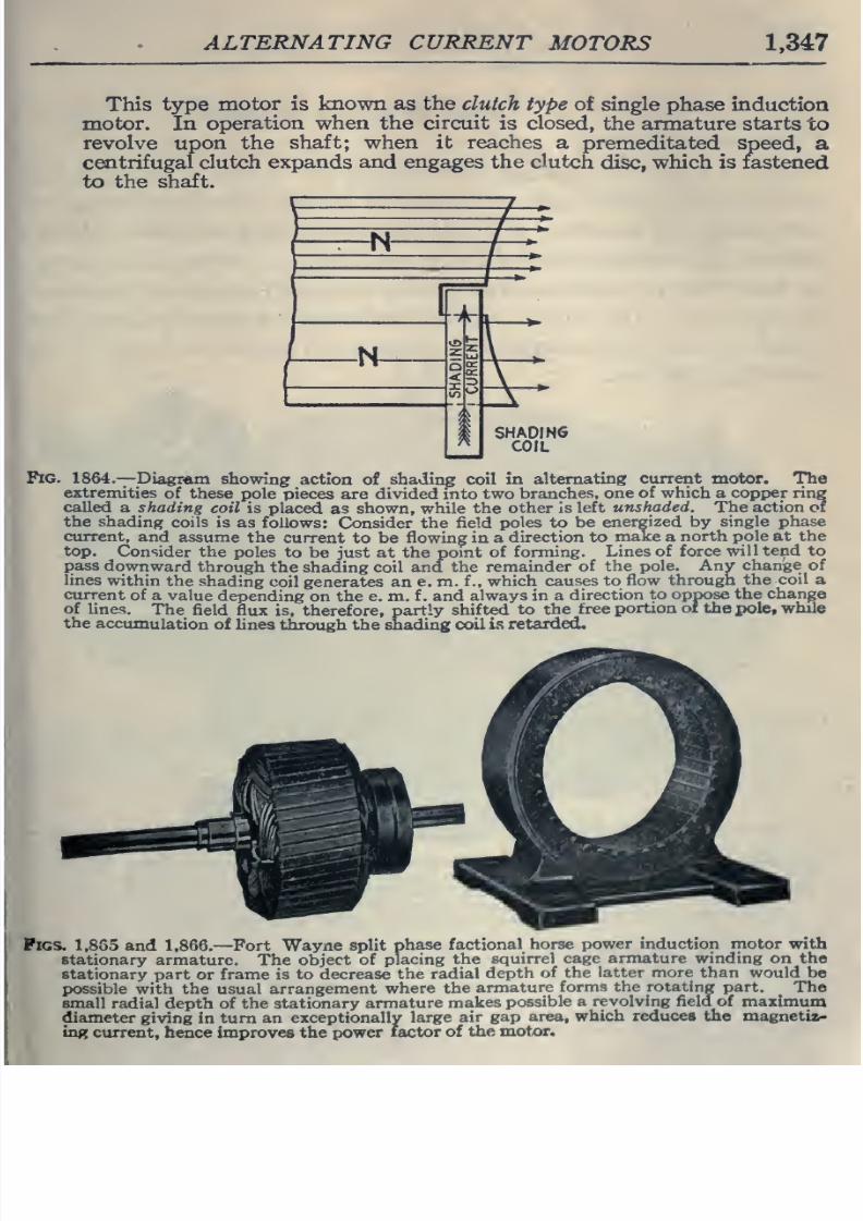
8/20/2019 electrical guide 5.pdf
http://slidepdf.com/reader/full/electrical-guide-5pdf 93/343
ALTERNATING CURRENT
MOTORS
1,347
This
type
motor
is
known as
the
clutch
type
of
single
phase
induction
motor.
In
operation when the
circuit
is
closed,
the
armature
starts
to
revolve
upon
the
shaft; when it
reaches
a
premeditated
speed,
a
centrifugal
clutch
expands and engages
the
clutch
disc,
which is
fastened
to the
shaft.
-N-
-N-
Fig.
1864.
—
Diagram
showing
action
of
shading coil
in
alternating
current
motor.
The
extremities
of
these
pole
pieces
are
divided into
two
branches,
one
of
which
a
copper
ring
called
a
shading
coil
is placed
as
shown, while the
other is
left
unshaded.
The
action
or
the
shading
coils is
as
follows: Consider
the
field
poles
to
be
energized
by
single
phase
current,
and assume
the
current
to be
flowing in
a
direction to
make
a
north
pole
at
the
top.
Consider the
poles
to
be
just
at
the
point
of forming.
Lines of
force
will tend to
pass
downward
through
the
shading coil
and
the
remainder
of
the
pole.
Any
change
of
lines
within
the
shading
coil generates an
e. m.
f
.,
which
causes
to
flow
through
the
coil
a
current
of
a
value
depending
on
the e. m.
f . and
always in a
direction
to oppose
the
change
of
lines.
The field
flux
is,
therefore,
partly
shifted
to
the
free
portion
of
the
pole,
while
the
accumulation
of
lines
through
the shading
coil
is
retarded.
Pigs.
1,855
and 1,866.
—
Fort
Wayne split
phase
factional
horse
power
induction
motor
with
stationary armature.
The
object
of
placing
the
squirrel
cage armature
winding
on the
stationary
part
or frame is
to
decrease
the
radial
depth
of the
latter more than would
be
possible with the
usual
arrangement
where
the
armature
forms the rotating
part.
The
small
radial depth of the stationary
armature
makes
possible a
revolving
field
of
maximum
diameter
giving in
turn
an exceptionally
large
air
gap
area,
which
reduces
the
magnetix.-
ing
ctirrent, hence
improves the
power
factor of
the motor.
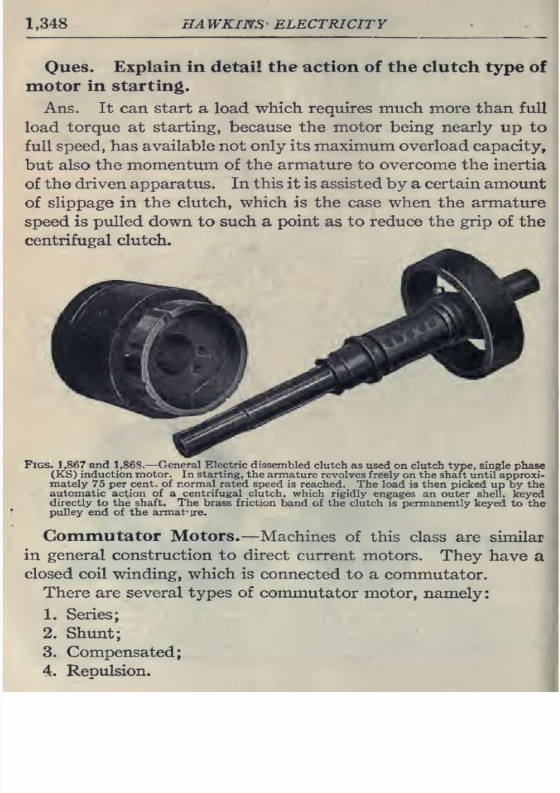
8/20/2019 electrical guide 5.pdf
http://slidepdf.com/reader/full/electrical-guide-5pdf 94/343
1,348
HAWKINS'
ELECTRICITY
Oues.
Explain
in
detail
the
action
of
the
clutch type
of
motor
in starting.
Ans.
It
can
start
a
load
which requires much
more
than
full
load
torque at
starting, because
the
motor being
nearly
up
to
full
speed,
has
available
not
only
its
maximum
overload
capacity,
but also
the momentum
of
the
armature
to
overcome
the inertia
of
the driven
apparatus.
In
this
it
is
assisted by a certain
amount
of
slippage
in
the
clutch,
which is the
case
when
the
armature
speed is
pulled
down
to such
a
point
as
to reduce the
grip
of
the
centrifugal
clutch.
Figs.
1,867
and
1,868.—
General
Electric
dissembled
clutch as used
on clutch
type,
single phase
(KS)
induction
motor.
In
starting, the
armature
revolves
freely
on
the
shaft
until
approxi-
mately
75
per
cent, of
normal
rated
speed
is
reached.
The
load
is
then
picked
up
by
the
automatic
action
of
a
centrifugal
clutch,
which
rigidly engages
an
outer
shell,
keyed
directly to
the
shaft.
The
brass
friction
band
of the clutch
is
permanently
keyed
to
the
pulley end of the armat-ire.
Commutator
Motors.
—Machines
of
this
class
are
similar
in general
construction
to
direct
current motors.
They
have
a
closed coil winding, which is
connected to a
commutator.
There
are
several
types
of
commutator motor,
namely:
1.
Series;
2.
Shunt;
3.
Compensated;
4. Reoulsion.
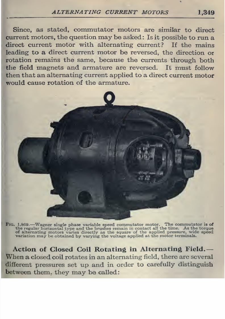
8/20/2019 electrical guide 5.pdf
http://slidepdf.com/reader/full/electrical-guide-5pdf 95/343
ALTERNATING
CURRENT
MOTORS
1,349
Since,
as
stated,
commutator
motors
are
similar
to
direct
current
motors, the question may
be
asked:
Is
it
possible
to run
a
direct
current motor
with
alternating
current?
If the
mains
leading
to
a
direct
current
motor
be
reversed,
the
direction
or
rotation
remains the
same,
because
the
currents
through
both
the
field
magnets
and armature
are
reversed.
It
must
follow
then
that an
alternating
current
applied to
a direct
current
motor
would
cause rotation of the
armature.
Fig.
1,869.
—
Wagner
single phase
variable
speed
commutator
motor.
The commutator
13 ot
the
regular
horizontal
type
and
the brushes
remain
in
contact
all
the
time.
As
the
torque
of
alternating
motors
varies directly as
the square
of
the
applied
pressure, wide
speed
variation may
be
obtained
by
varying
the
voltage
applied
at
the
motor
terminals.
Action
of
Closed Ck>il
Rotating
in
Alternating
Field.—
When
a
closed
coil rotates
in an
alternating
field, there are
several
different
pressures
set
up
and
in
order
to
carefully distinguish
between
them,
they may
be
called:
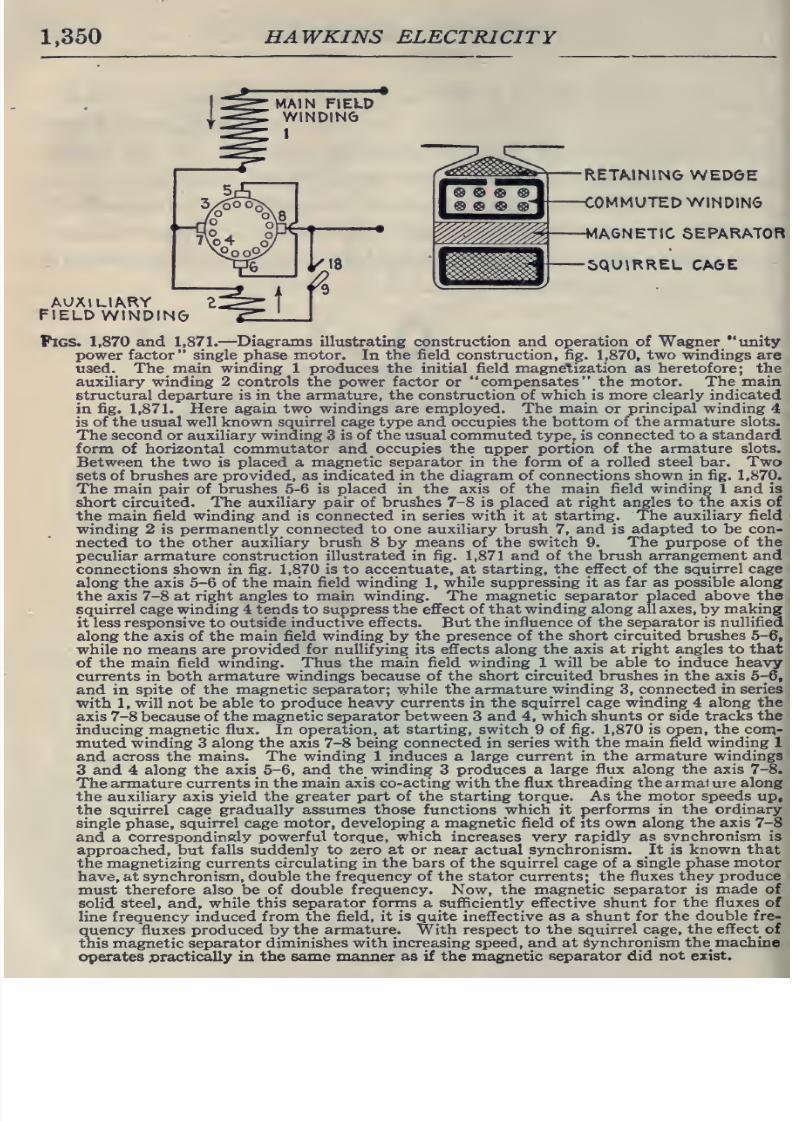
8/20/2019 electrical guide 5.pdf
http://slidepdf.com/reader/full/electrical-guide-5pdf 96/343
1,350
HAWKINS
ELECTRICITY
RETAINING
WEDGE
COMMUTED WINDING
MAGNETIC SEPARATOR
^
^
SQUIRREL
CAGE
^
^
^
V^^^^
^
AUXILIARY
FIELD
WINDING
Figs.
1,870
and
1,871.
—
Diagrams
illustrating
construction
and
operation
of
Wagner
unity
power factor single
phase
motor.
In
the
field
construction, fig.
1,870,
two windings are
used. The main winding
1
produces the
initial
field
magnetization as
heretofore; the
auxiliary
winding
2 controls
the power
factor
or
compensates
the
motor.
The
main
structural
departure is in
the armature, the
construction
of which
is
more clearly indicated
in
fig.
1,871.
Here
again two
windings
are employed. The main
or
principal
winding
4
is
of
the
usual
well
known
squirrel
cage
type and
occupies
the bottom of
the
armature slots.
The second
or auxiliary
winding
3
is of the usual commuted
type,
is
connected to a standard
form of
horizontal
commutator
and
occupies
the upper
portion
of
the armature slots.
Between
the two
is
placed
a
magnetic
separator
in
the form
of
a
rolled steel bar.
Two
sets of brushes are provided,
as indicated in the diagram of
connections
shown in fig.
1,870.
The main
pair
of
brushes
5-6
is
placed in the
axis
of the main field winding 1
and
is
short
circuited.
The
auxiliary pair of
brushes
7-8
is
placed
at
right angles to the
axis of
the
main
field
winding
and
is
connected
in
series
with
it
at
starting.
The
auxiliary
field
winding
2
is
permanently connected to one auxiliary brush
7,
and
is
adapted to be
con-
nected
to
the other
auxiliary brush
8
by
means
of
the switch 9.
The purpose of the
peculiar armature
construction illustrated in
fig.
1,871
and
of the brush arrangement and
connections
shown
in
fig.
1,870
is
to
accentuate,
at starting, the effect of the
squirrel
cage
along
the axis
5-6
of the
main
field
winding
1,
while
suppressing
it
as
far
as possible
along
the axis
7-8
at
right
angles
to
main
winding.
The
magnetic
separator
placed
above the
squirrel
cage
winding
4 tends to suppress
the
effect
of that winding along all axes, by
making
it less responsive
to
outside
inductive
effects.
But
the
influence
of
the separator
is
nullified
along the axis of
the
main
field
winding
by
the presence
of
the
short circuited brushes
5-6,
while
no
means
are
provided for
nullifying
its
effects
along
the
axis at right angles to that
of
the
main
field
winding.
Thus the
main field winding 1
will
be
able
to induce
heavy
currents in
both armature
windings
because
of
the
short circuited
brushes
in
the
axis 5-6,
and
in
spite
of
the
magnetic separator; while the armature
winding
3,
connected in series
with
1,
will
not be
able
to produce heavy
currents
in
the
squirrel
cage winding
4
along
the
axis
7-8
because
of the magnetic
separator between
3 and
4,
which
shunts or
side tracks
the
inducing magnetic flux. In
operation, at starting,
switch
9 of fig.
1,870
is open, the
con;-
muted
winding
3
along
the axis
7-8
being
connected
in
series
with the main field winding 1
and
across
the
mains. The winding
1 induces a
large
current in
the
armature windings
3 and 4
along
the
axis 5-6,
and
the
winding
3
produces a
large flux along the axis
7-8.
The
armature
currents
in
the main axis
co-acting
with
the flux
threading the armal
ure
along
the
auxiliary
axis
yield
the greater
part
of
the
starting
torque. As the motor speeds up,
the
squirrel cage
gradually
assumes those
functions
which
it
performs
in
the
ordinary
single
phase,
squirrel
cage
motor,
developing
a magnetic field of its own
along the
axis
7-8
and
a
correspond
in
ely
powerful torque, which
increases
very rapidly as
synchronism
is
approached,
but
falls
suddenly
to
zero
at
or near
actual
synchronism.
It is
known
that
the
magnetizing
currents circulating in
the bars
of the squirrel cage of a
single
phase
motor
have,
at
synchronism, double
the
frequency of
the
stator
currents; the fluxes
they produce
must
therefore also be of
double frequency. Now, the magnetic
separator is
made
of
solid
steel, and,
while
this separator forms
a sufficiently
effective shunt for
the
fluxes
of
line
frequency
induced
from
the
field,
it is quite
ineffective
as
a shunt
for the
double
fre-
quency fluxes produced
by
the armature. With respect to
the
squirrel
cage,
the
effect
of
this magnetic
separator
diminishes with increasing speed, and
at
Synchronism
the_
machine
operates ©ractically
ia
the
same
manner
as
if the magnetic
separator
did
not exist.
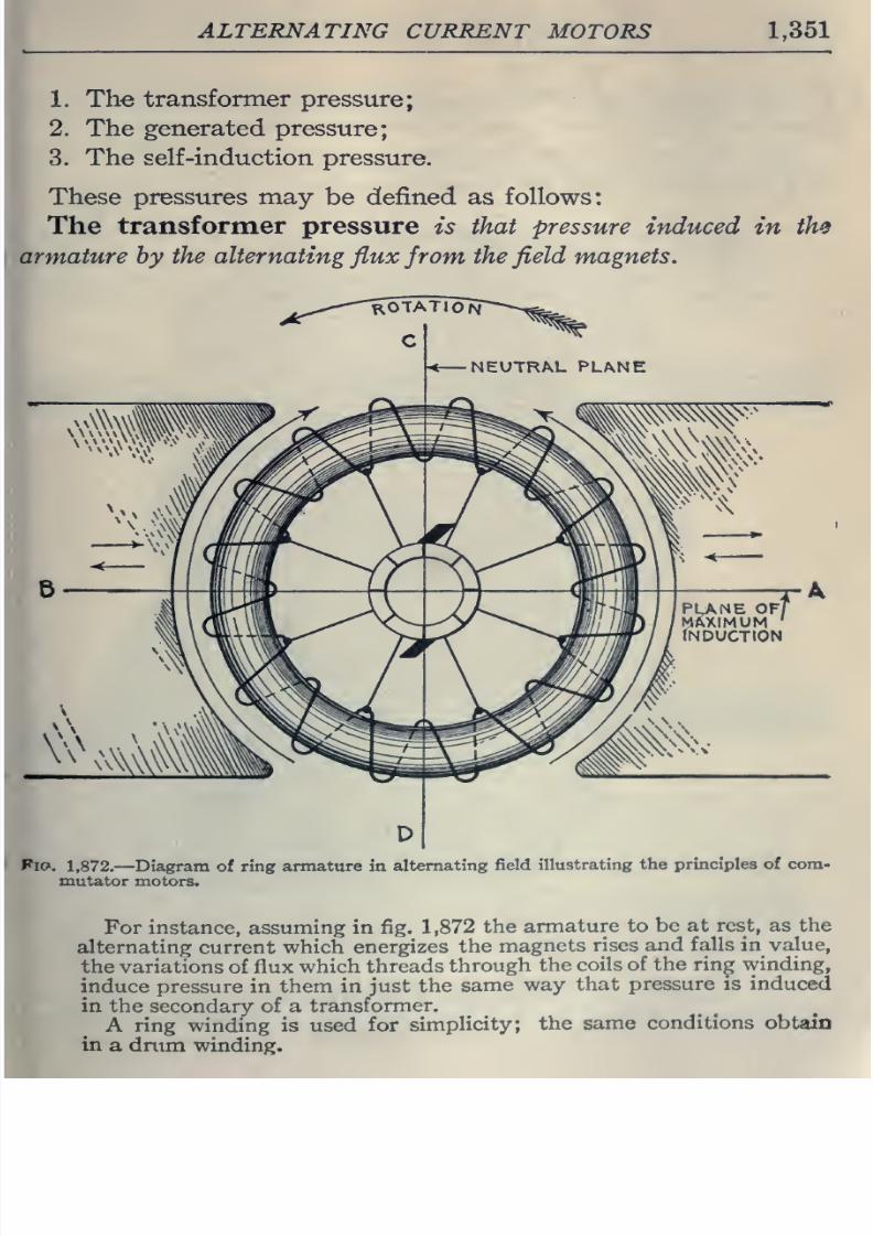
8/20/2019 electrical guide 5.pdf
http://slidepdf.com/reader/full/electrical-guide-5pdf 97/343
ALTERNATING
CURRENT
MOTORS
1,351
1. The
transformer pressure;
2. The
generated
pressure;
3. The
self-induction
pressure.
These pressures
may
be
defined as follows:
The transformer pressure is that pressure
induced
in
the
armature
by
the
alternating
flux
from
the
field
magnets.
Fio.
1,872.
—
Diagram
of ring
armature
in
alternating
field
illustrating the
principles
of com-
mutator
motors.
For instance, assuming in fig.
1,872
the
armature
to
be
at
rest,
as
the
alternating
current
which
energizes
the
magnets
rises
and
falls
in
value,
the
variations
of
flux
which
threads
through
the
coils of the
ring winding,
induce pressure in them in
just
the
same
way
that
pressure
is induced
in
the
secondary
of
a
transformer.
A
ring
winding is used
for
simplicity;
the
same
conditions
obtain
in
a
dnira
winding.
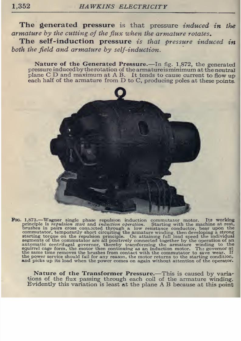
8/20/2019 electrical guide 5.pdf
http://slidepdf.com/reader/full/electrical-guide-5pdf 98/343
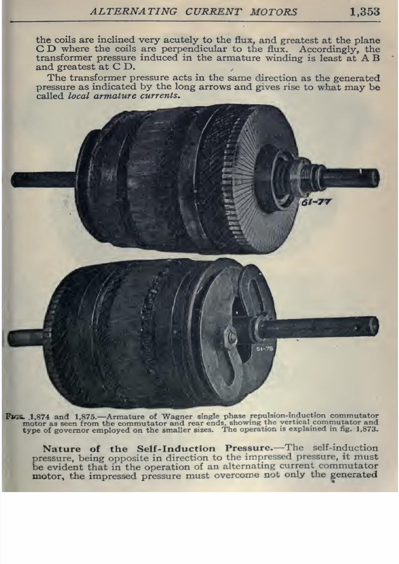
8/20/2019 electrical guide 5.pdf
http://slidepdf.com/reader/full/electrical-guide-5pdf 99/343
ALTERNATING
CURRENT
MOTORS
1,353
the
coils
are
inclined very acutely
to
the
flux,
and
greatest
at
the
plane
C
D
where the
coils
are
perpendicular
to
the
flux. Accordingly, the
transformer pressure
induced in
the
armature
winding
is
least at A
B
and
greatest
at
C
D.
The
transformer
pressure
acts
in the same
direction
as
the
generated
pressure
as indicated
by
the
long
arrows
and
gives
rise
to
what
may
be
called local
armature
currents.
Fks.
.1,874
and 1,875.—
Armature
of Wagner
single
phase
repulsion-induction
commutator
motor
as
seen
from
the
commutator
and
rear
ends,
showing
the
vertical
commutator
and
type
of
governor
employed
on
the
smaller
sizes.
The
operation
is
explamed
in
fig.
1,873.
Nature of the
Self-induction
Pressure.—
The
self-induction
pressure,
being
opposite
in
direction
to
the
impressed
pressure,
it
must
be
evident that in
the
operation
of
an
alternating
current
commutator
motor,
the
impressed
pressure
must
overcome
not
only
the
generated
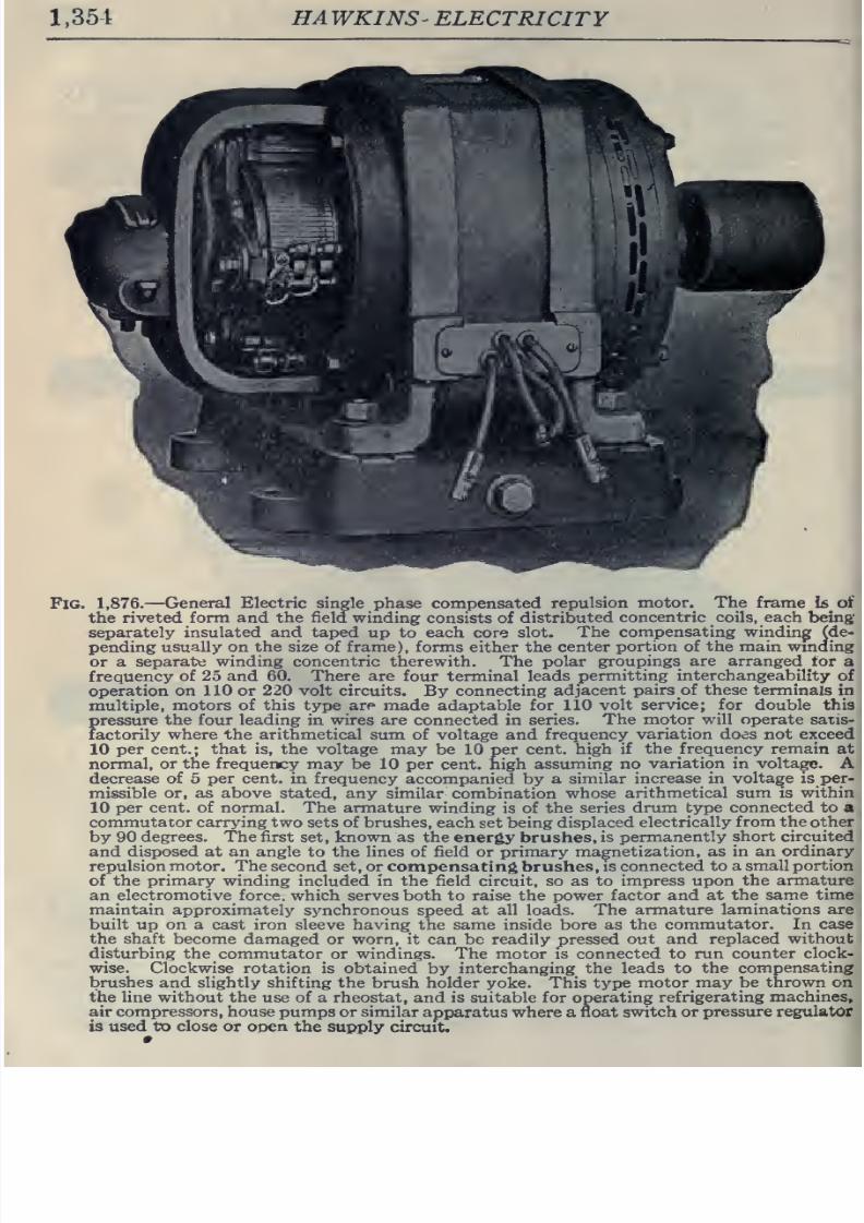
8/20/2019 electrical guide 5.pdf
http://slidepdf.com/reader/full/electrical-guide-5pdf 100/343
1,351
HA
WKINS'
ELECTRICITY
Fig.
1,876.
—
General
Electric
single
phase
compensated
repulsion
motor.
The
frame
\& oi
the
riveted
form
and the field winding
consists
of
distributed
concentric coils, each
being
separately insulated
and taped up
to
each
core
slot.
The
compensating
winding
(de-
pending
usually on
the
size
of
frame), forms
either the
center
portion of
the
main
wmding
or
a
separate
winding concentric
therewith.
The
polar
groupings are arranged tor
a
frequency
of
25 and 60.
There
are
four
terminal
leads
permitting
interchangeability
of
operation
on
110
or
220
volt circuits.
By
connecting
adjacent
pairs
of
these
terminals
in
multiple,
motors
of
this
type
are
made adaptable for 110
volt service;
for
double
this
pressure
the
four
leading in wires are connected
in
series.
The motor
will
operate satis-
factorily
where the arithmetical
sum
of voltage and
frequency
variation does
not
exceed
10
per
cent.;
that
is,
the
voltage
may
be
10
per
cent,
high
if
the
frequency
remain
at
normal,
or
the
frequency
may be 10
per
cent, high
assuming
no
variation
in
voltage.
A
decrease
of 5
per
cent,
in
frequency
accompanied
by
a
similar
increase
in
voltage
is per-
missible or,
as
above stated,
any
similar
combination
whose
arithmetical
sum
is within
10
per cent, of
normal.
The
armature
winding
is
of the
series drum
type
connected
to
a
commutator
carrying
two sets of
brushes,
each
set
being
displaced
electrically
from the other
by
90
degrees. The first
set, known
as
the
energy brushes,
is
permanently
short
circuited
and
disposed at an
angle to
the
lines of
field or
primary
magnetization,
as in
an
ordinary
repulsion
motor.
The
second set, or compensating
brushes,
is
connected to
a small
portion
of the
primary
winding
included in
the
field circuit, so
as
to
impress upon
the
armature
an
electromotive
force, which serves both
to
raise
the
power factor
and
at the
same
time
maintain approximately
synchronous speed at
all
loads.
The armature
laminations are
built
up on a cast iron
sleeve
having
the
same
inside
bore as the
commutator.
In
case
the shaft
become
damaged
or
worn, it
can
be
readily
pressed
out
and
replaced
without
disturbing the
commutator or windings.
The
motor is connected to
run
counter
clock-
wise,
clockwise
rotation is
obtained
by
interchanging
the
leads to
the compensating
brushes and slightly
shifting the
brush holder
yoke. This type
motor may be
thrown on
the
line without
the
use of
a rheostat,
and
is suitable
for
operating
refrigerating
machines,
air compressors,
house
pumps
or similar
apparatus
where a
float
switch
or
pressure regulator
is
used
to
close
or open
the
supply
circuit.
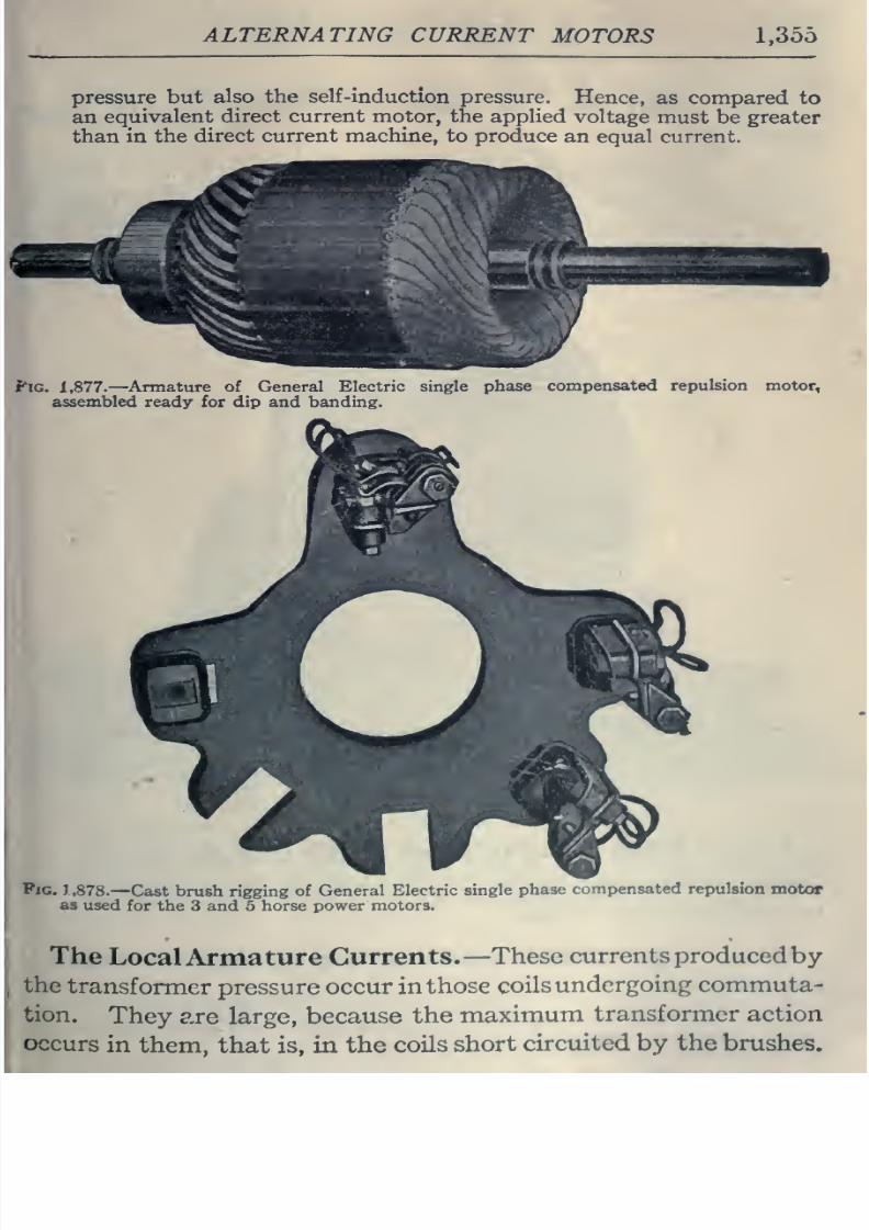
8/20/2019 electrical guide 5.pdf
http://slidepdf.com/reader/full/electrical-guide-5pdf 101/343
ALTERNATING
CURRENT
MOTORS
1,355
pressure
but
also the self-induction
pressure.
Hence,
as
compared to
an
equivalent
direct
current motor, the applied
voltage
must be greater
than
in
the
direct
current
machine,
to produce
an
equal
current.
fiG.
1,877.
—
Armature
of
General
Electric
single
phase
compensated
repulsion
motor,
assembled
ready
for
dip
and
banding.
Fig.
1.878.
—Cast
brush
rigging
of
General Electric
single
phase
compensated repulsion
motor
as
used
for the 3 and 5 horse power
motors.
The
LocalArmature
Currents.
—
These
currents
produced
by
the
transformer
pressure
occur
in
those
coils
undergoing
commuta-
tion.
They
are
large,
because
the
maximum
transformer action
occurs
in
them,
that is, in
the
coils
short
circiiited by the
brushes.
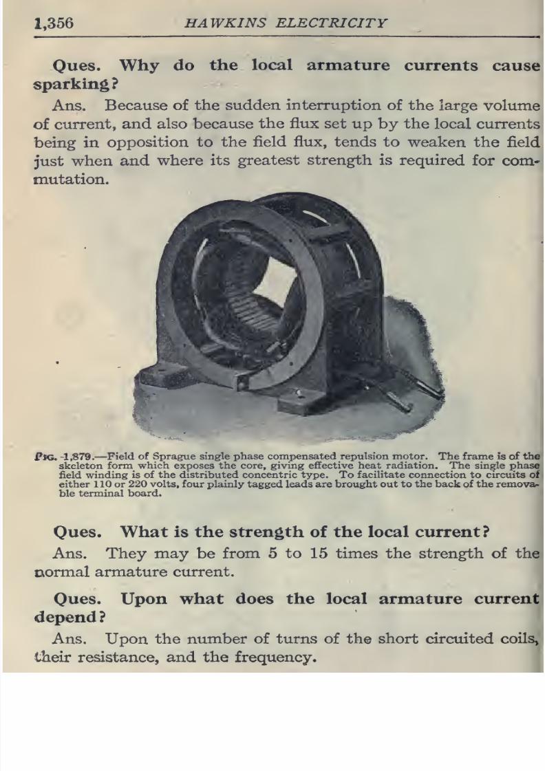
8/20/2019 electrical guide 5.pdf
http://slidepdf.com/reader/full/electrical-guide-5pdf 102/343
1,356
HAWKINS
ELECTRICITY
Ones.
Why
do
the
local
armature
currents
cause
sparking?
Ans.
Because of the
sudden interruption
of the large
volume
of
current,
and
also because
the flux
set up
by
the
local currents
being
in
opposition to
the
field
flux,
tends
to weaken
the
field
just
when
and
where its
greatest
strength
is required
for com-
mutation.
Fig.
-1,879.
—
Field
of
Sprague
single phase
compensated repulsion motor.
The frame is of
the
skeleton
form
which
exposes the core,
giving
effective heat radiation. The single phase
field winding
is
of the
distributed concentric
type.
To
facilitate
connection
to
circuits of
either
110
or
220
volts,
four
plainly
tagged
leads are
brought
out to
the
back
of the
remova-
ble
terminal
board.
Oues.
What
is
the
strength
of
the local current?
Ans.
They
may
be
from
5
to
15
times the
strength
of
the
txormal
armature
current.
Oues.
Upon
what does
the
local
armature
current
depend
?
Ans.
Upon
the
number of
turns
of
the
short circuited
coils»
their resistance, and
the
frequency.
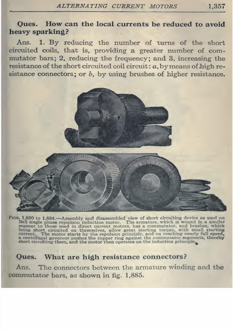
8/20/2019 electrical guide 5.pdf
http://slidepdf.com/reader/full/electrical-guide-5pdf 103/343
ALTERNATING
CURRENT
MOTORS
1,357
Oues.
How can the
local currents
be
reduced to
avoid
heavy
sparking?
Ans.
1.
By
reducing
the number
of
turns
of
the
short
circuited
coils,
that
is,
providing
a
greater
number
of
com-
mutator bars;
2,
reducing
the
frequency;
and
3,
increasing
the
resistance
of the
short
circuited
coil circuit
: a,
bymeans of thigh
re-
sistance
connectors;
or
6,
by
using
brushes of higher
resistance.
^M
4^«B
Figs.
1,880
to
1,884.
—Assembly and
disassembled
view
of
short
circuiting
device
as
used
on
Bell
single
phase
repulsion
induction motor.
The
armature,
which
is
wound
in a
similar
manner
to
those used
in
direct
current
motors,
has a
commutator,
and brushes,
which
being
short
circuited
on
themselves,
allow
great
starting
torque,
with small
starting
current.
The
motor starts by the repulsion
principle,
and on
reaching nearly full speed,
a
centrifugal
governor
pushes
the
copper
ring
against
the
commutator segments,
thereby
short
circuiting
them,
and the motor then
operates on
the
induction
principle^
Oues.
What
are high
resistance
connectors?
Ans.
The
connectors between
the
armature
winding
and
the
commutator
bars,
as shown in
fig.
1,885.
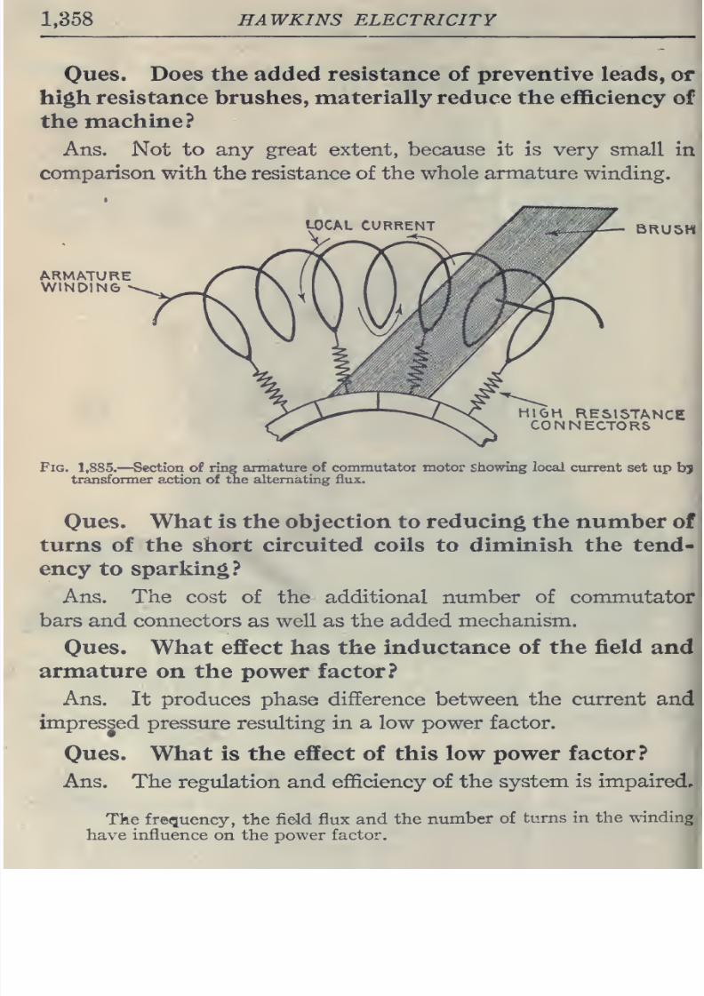
8/20/2019 electrical guide 5.pdf
http://slidepdf.com/reader/full/electrical-guide-5pdf 104/343
1,358
HAWKINS
ELECTRICITY
Owes.
Does the added resistance
of
preventive
leads,
or
high
resistance
brushes,
materially
reduce
the efficiency
of
the
machine?
Ans.
Not
to
any
great
extent,
because
it
is
very
small
in
comparison
with the resistance
of
the
whole armature
winding.
LOCAL
CURRENT
BRUSH
HIGH
RESISTANCE
CONNECTORS
Fig.
1,885.
—
Section of
ring
armature
of commutatoi motor showing
local
current
set
up
bj
transformer action
of
the
alternating
flux.
Oues.
What is
the
objection
to
reducing the number
of
turns
of
the short
circuited coils
to
diminish
the
tend-
ency
to
sparking?
Ans. The cost
of
the additional number of commutator
bars
and
connectors
as
well
as the
added
mechanism.
Oues.
What effect
has
the inductance
of
the
field
and
armature
on
the
power
factor?
Ans.
It
produces phase difference
between
the
current
and
impressed
pressure
residting in
a
low power
factor.
Ones.
What
is
the
effect
of
this
low
power
factor?
Ans.
The
regulation
and efficiency
of the
system is
impaired,
Tke frequency,
the
field flux
and the
number
of
turns
in
the
winding
have
influence
on
the power
factor.
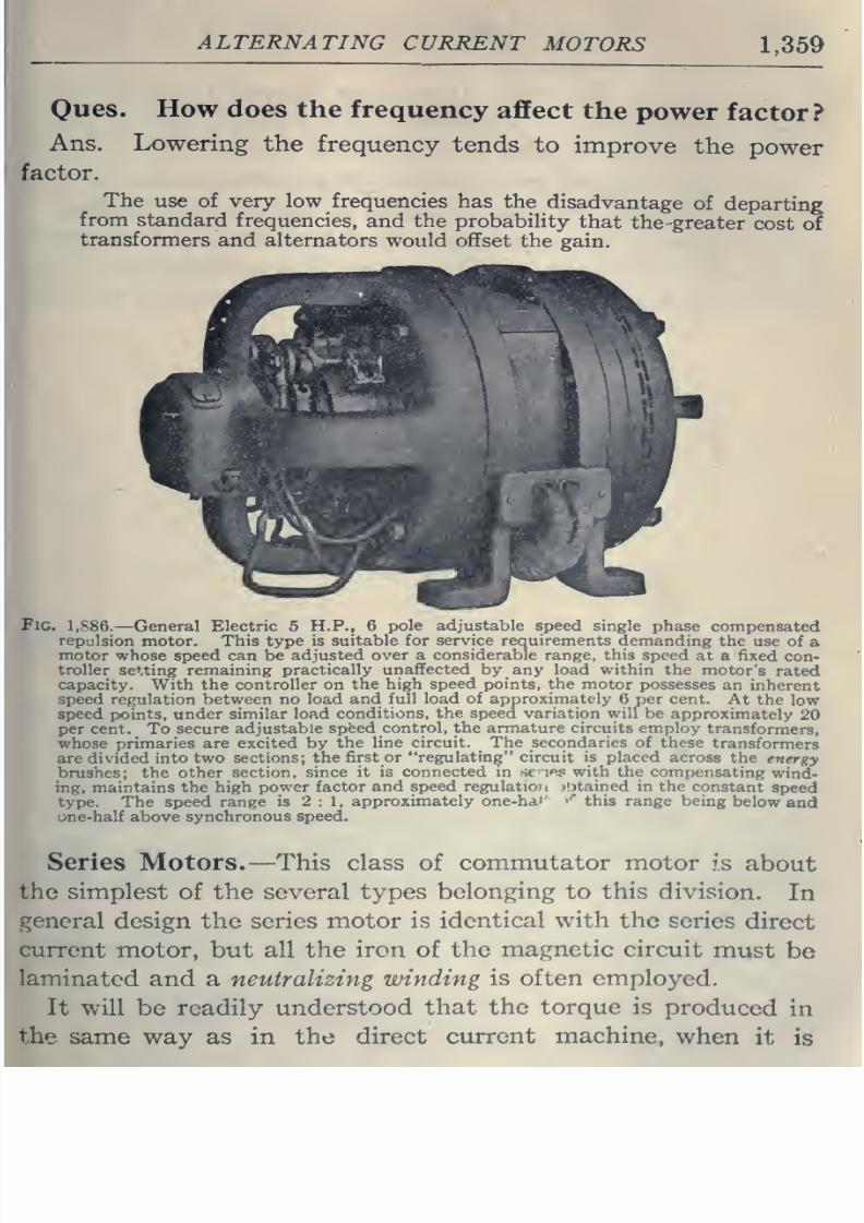
8/20/2019 electrical guide 5.pdf
http://slidepdf.com/reader/full/electrical-guide-5pdf 105/343
ALTERNATING
CURRENT
MOTORS
1,359
Oues.
How
does
the
frequency
affect
the
power
factor?
Ans. Lowering
the
frequency
tends
to
improve
the
power
factor.
The
use
of
very
low
frequencies
has
the
disadvantage
of
departing
from
standard
frequencies,
and the probability
that
the-greater
cost
of
transformers
and alternators
would
offset
the gain.
Fig.
1,886.
—
General Electric 5
H.P., 6
pole adjustable
speed
single
phase
compensated
repulsion
motor. This type
is suitable
for
service
requirements
demanding
the
use of
a
motor
whose
speed can
be
adjusted
over
a
considerable
range,
this
speed
at a
fixed
con-
troller
setting
remaining
practically
unaffected
by
any
load
within
the
motor's
rated
capacity.
With
the
controller
on
the high
speed
points, the motor
possesses
an
inherent
speed regulation between no
load
and full
load
of
approximately
6
per
cent.
At
the
low
speed
points,
under
similar
load
conditions,
the
speed
variation will
be
approximately
20
per
cent.
To
secure
adjustable
speed
control,
the armature
circuits
employ
transformers,
whose
primaries
are excited
by
the
line
circuit.
The
secondaries
of
these
transformers
are divided into
two sections;
the
first
or
regulating
circuit
is
placed
across
the
energy
brushes; the
other
section,
since it
is
connected
m
scuffs
with the
compensating
wind-
ing,
maintains
the
high power
factor
and speed regulatioji
obtained
in the
constant
speed
type.
The
speed range
is
2:1,
approximately
one-hdi'
''
this range
being
below
and
une-half
above
synchronous
speed.
Series Motors.
—
This
class
of
commutator
motor
is
about
the simplest
of
the several types
belonging
to this
division.
In
general
design the
series
motor
is
identical
with the
scries
direct
current
motor,
but all the
iron
of
the
magnetic circuit
must
be
laminated
and
a
neutralizing
winding
is often
employed.
It
will
be readily
understood
that
the torque is
produced
in
the same
way
as
in
the
direct
current
machine,
when
it
is
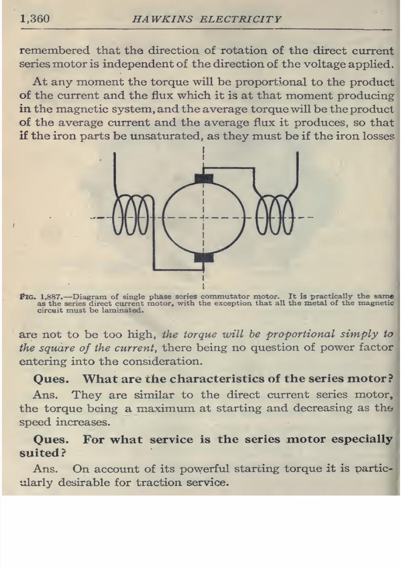
8/20/2019 electrical guide 5.pdf
http://slidepdf.com/reader/full/electrical-guide-5pdf 106/343
1,360
HAWKINS ELECTRICITY
remembered
that
the
direction, of
rotation
of
the direct
current
series
motor is independent
of
the
direction
of
the
voltage
applied.
At
any
moment
the
torque
will
be
proportional
to
the
product
of the current
and
the
flux which
it is at that moment producing
in
the magnetic system, and the
average torque
will
be
the
product
of the
average
current and the average flux it produces, so
that
if
the iron
parts
be
unsaturated,
as they
must
be
if the
iron losses
Pig.
1,887.—Diagram
of
single
phase
scries
commutator motor.
It
is
practically
the
same
as
the
series
direct current
motor,
with
the
exception that
all the
metal
of
the magnetic
circuit
must
be
laminated.
are not to
be
too
high, the
torque will
be
proportional
simply
to
the
square
of
the
current,
there
being
no
question
of
power
factor
entering
into
the
consideration.
Ques.
What
are
the
characteristics
of
the
series motor
?
Ans.
They
are similar
to the
direct current
series motor,
the
torque being
a
maximum
at
starting and
decreasing
as
the
speed
increases.
Ones.
For
what
service
is
the
series
motor
especially
suited
?
Ans.
On account
of
its
powerful
starting
torque it
is
partic-
ularly desirable
for
traction
service.
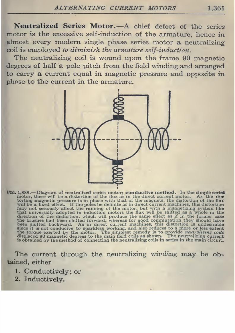
8/20/2019 electrical guide 5.pdf
http://slidepdf.com/reader/full/electrical-guide-5pdf 107/343
ALTERNATING
CURRENT
MOTORS
1,361
Neutralized Series
Motor.—
A chief
defect
of
the
series
motor
is
the
excessive
self-induction
of
the
armature,
hence
in
almost
every
modem
single
phase
series
motor
a neutralizing
coil
is
employed
to
diminish
the
armature
self-induction.
The
neutralizing
coil is
wound
upon
the
frame
90 magnetic
degrees of
half
a
pole
pitch from
the
field winding
and
arranged
to
carry
a
current equal
in magnetic
pressure
and
opposite
in
ph3,se to
the
current
in
the
armature.
Pig.
1,888.
—
Diagram
of
neutralized series
motor;,
conductive
method.
In the
simple
series
motor,
there
will
be
a
distortion of the flux as
in
the direct
current
motor.
As the
di*
torting
magnetic
pressure is in
phase
with that
of
the
magnets,
the
distortion
of
the
fluj.)
will
be a
fixed effect.
If
the
poles
be
definite as in
direct
current
machines,
this
distortion
may
not
seriously
affect the running of
the motor,
but
with
a
magnetizing
system
like
that
universally
adopted
in
induction
motors
the
flux
will be
shifted as
a whole
in
the
direction
of the distortion, which will
produce
the
same
effect
as if
in the former
case
the
brushes
had been shifted forward,
whereas
for
good
commutation
they
should
have
been
shifted
backward.
As in direct
current
machines,
this
distortion
is
undesirable
since
it
is
not conducive
to
sparkless
working,
and
also
reduces to
a
more
or less
extent
the
torque
exerted by
the
motor.
The
simplest
remedy
is to
provide
neutralizing
coils
displaced
90
magnetic degrees to the
main
field
coils as
shown.
The neutralizing
current
is
obtained
by the
method
of connecting
the
neutralizing
coils
in
series
in
the
main
circuit.
The
current
through
the
neutralizing
wirdmg
may
be
ob*
tained,
either
1.
Conductively;
or
2.
Inductively.
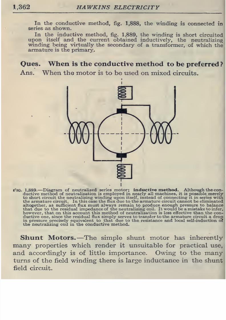
8/20/2019 electrical guide 5.pdf
http://slidepdf.com/reader/full/electrical-guide-5pdf 108/343
1,362
HAWKINS
ELECTRICITY
In the conductive method,
fig.
1,?
series
as
shown.
the winding
is
connected
in
In
the
inductive
method,
fig.
1,889,
the winding
is
short
circuited
upon
itself
and^ the current
obtained
inductively,
the
neutralizing
winding
being virtually
the secondary
of
a
transformer,
of
which
the
armature
is the
primary.
Oues.
When is the conductive
method
to
be
preferred
?
Ans.
When
the
motor is
to
be
used
on
mixed
circuits.
t''lG.
1,889.
—
Diagram
of
neutralized series motor;
inductive method.
Although the
con-
ductive
method
of
neutralization
is
employed
in
nearly
all
machines,
it
is
possible
merely
to short
circuit
the
neutralizing
winding
upon
itself, instead of connecting it
in
series
with
the
armature circuit.
In
this case the flux
due
to
the armature
circuit
cannot be eliminated
altogether,
as sufficient
flux
must
always remain
to
produce
enough
pressure
to
balance
that
due
to
the
residual
impedance
of the
neutralizing
coil. It
would
be
a
mistake
to
infer,
however,
that
on
this account this
method
of neutralization
is
less
effective
than
the
con-
ductive
one,
since
the residual
flux
simply
serves
to
transfer
to
the armature
circuit
a
drop
in
pressure
precisely equivalent to
that
due
to
the
resistance and local self-induction of
the
neutralizing
coil in
the conductive
method.
Shunt
Motors.
—
The
simple shunt
motor
has inherently
many
properties
which
render
it
unsuitable
for
practical
use,
and
accordingly
is
of
little
importance.
Owing
to the
many
turns of
the
field winding there
is
large
inductance in
the
shunt
field
circuit.
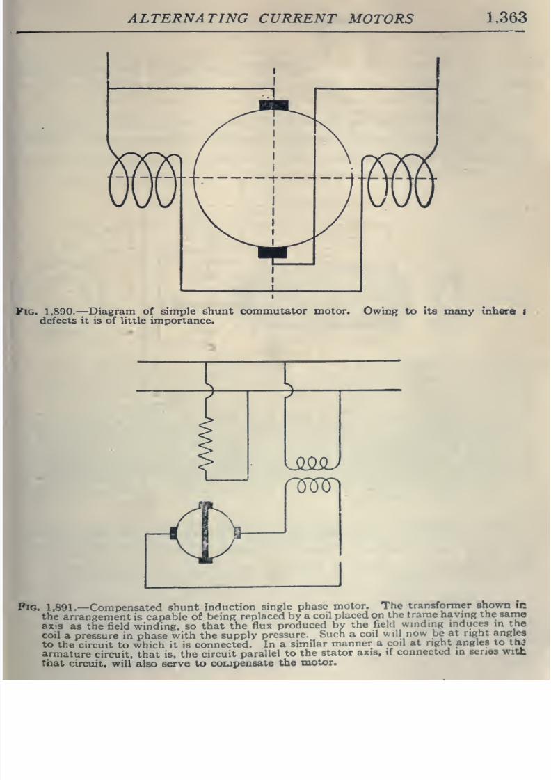
8/20/2019 electrical guide 5.pdf
http://slidepdf.com/reader/full/electrical-guide-5pdf 109/343
ALTERNATING
CURRENT
MOTORS
1,363
Pig.
1,890.
—
Diagram
of
simple
shunt
commutator
motor,
defects
it
is of little importance.
OwinR
to
its
many
inhera
I
>
Kt^
Pig.
1,891.—
Compensated
shunt
induction
single
phase
motor.
The
transformer
shown
in
the
arrangement
is capable of
being
replaced
by a
coil
placed on
the
trame
having the
same
axis
as the
field winding,
so that
the
flux
produced
by
the
field
winding
mduces
m
the
coil
a pressure
in
phase
with the
supply
pressure.
Such
a
coil
will
now
be
at right
angles
to
the
circuit
to
which
it
is
connected.
In
a
similar
manner
a
coil
at
right angles
to
thj
armature
circuit,
that
is. the
circuit
parallel
to
the
stator
axis,
if connected
in scnos w:tL
that
circuit,
will
also
serve
to
corjpensate
the
motor.
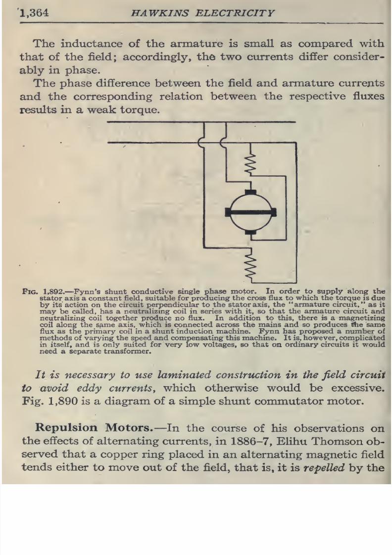
8/20/2019 electrical guide 5.pdf
http://slidepdf.com/reader/full/electrical-guide-5pdf 110/343
1,364
HAWKINS ELECTRICITY
The inductance of
the
armature is
small
as
compared
with
that of
the field; accordingly,
the
two
currents
differ
consider-
ably
in
phase.
The
phase
difference
between
the
field
and
armature
currents
and
the
corresponding relation between
the
respective
fluxes
results in
a
weak
torque.
€-€
Pig.
1,892.
—Pynn's shtint
conductive
single
phase motor.
In
order to
supply
along the
stator
axis
a constant
field,
suitable
for
producing
the
cross
flux
to which the
torque
is
due
by
its action on the
circuit perpendicular
to
the
stator
axis, the
armature
circuit,
as it
may be
called,
has a neutralizing
coil in series
with
it,
so
that the
armature
circuit
and
neutralizing
coil
together
produce
no
flux.
In
addition
to
this,
there is
a
magnetizing
coil
along the
same
axis, which is connected
across
the
mains
and
so produces l9ie same
flux
as
the
primary
coil
in
a shunt
induction machine. Fynn
has proposed a
number
of
methods
of
varying
the
speed
and
compensating
this
machine.
It
is,
however,
complicated
in itself,
and
is only
suited for
very
low voltages, so that on
ordinary circuits
it
would
need
a
separate transformer.
It
is necessary
to
use
laminated construction
in
the
field
circuit
to
avoid eddy
currents,
which
otherwise
would
be
excessive.
Fig.
1,890
is
a
diagram
of
a
simple
shunt commutator
motor.
Repulsion
Motors.
—
In
the
course
of
his
observations on
the effects
of
alternating
currents,
in 1886-7,
Elihu Thomson
ob-
served
that
a copper
ring
placed
in
an
alternating
magnetic
field
tends either
to
move
out
of
the field,
that
is,
it is
repelled by
the
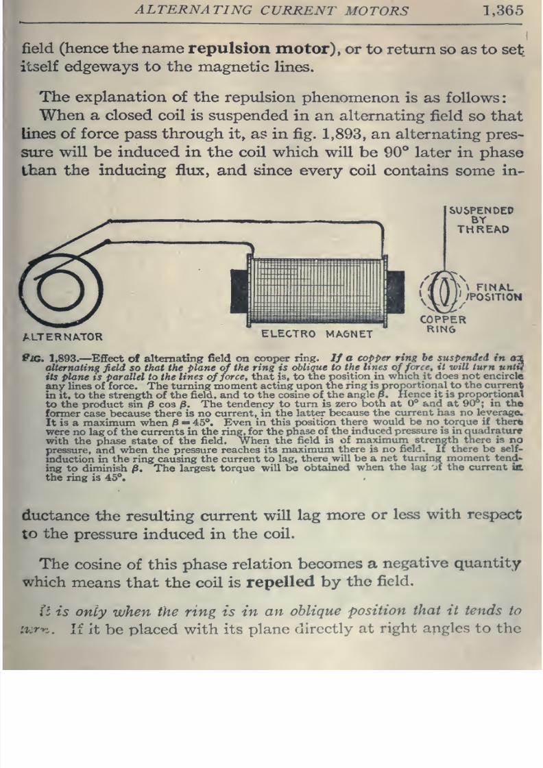
8/20/2019 electrical guide 5.pdf
http://slidepdf.com/reader/full/electrical-guide-5pdf 111/343
ALTERNATING
CURRENT
MOTORS
1,365
field
(hence the
name
repulsion
motor),
or
to
return
so as
to
set
itself
edgeways
to
the
magnetic
lines.
The
explanation
of the
repulsion
phenomenon
is
as
follows:
When
a
closed
coil
is
suspended
in
an
alternating
field
so
that
lines
of force pass through it, as
in
fig.
1,893,
an alternating pres-
sure
will
be induced
in
the
coil which
will be
90°
later in phase
than
the inducing
flux,
and
since every
coil contains
some
in-
ALTERNATOR
ELECTRO
MAGNET
PiG. 1,893.
—
^Effect
of
alternating
field on
cotiper
ring.
//
a
copper ting
he
suspended
in
aa
alternating
field
so that
the
plane
of
the
ring
is
oblique
to
the
lines
of
force,
it
will
turn untiS
its
plane
is
parallel
to the
lines
offeree,
that
is, to
the
position
in
which
it
does
not
encircle
any
lines
of
force.
The
turning
moment acting
upon the
ring is
proportional
to
the
current
in
it, to
the
strength
of
the
field,
and
to
the cosine
of
the
angle
p.
Hence it is
proportional
to the product
sin
/3
cos
jS.
The
tendency to turn is
zero
both at
0*
and
at
90*;
in
tha
former
case
because
there is no
current,
in
the
latter
because
the
current
has
no
leverage
It
is
a
maximum when
/3
=
45 .
Even in
this
position
there would be
no torque if there
were no lag
of
the
currents
in
the
ring,
for
the
phase of
the
induced
pressure is
in
Quadrature
with
the
phase
state
of
the field.
When
the
field is of
maximum strength there is
no
pressure,
and
when
the
pressure reaches
its
maximum
there
is
no
field.
It
there be self-
mduction in
the ring
causing
the
current
to lag,
there
will
be
a
net
turning moment
tend'
ing
to
diminish
/3.
The
largest
torque
will
be
obtained
when
the
lag
jf
the current
UL
the
ring
is
45°.
ductance
the resulting
current
will
lag
more
or
less
with
respect
to
the
pressure
induced in
the
coil.
The
cosine
of
this
phase
relation
becomes
a
negative
quantity
which
means
that
the
coil
is
repelled
by
the
field.
(t
is
only
when
the
ring
is
in
an
oblique
position
that
it
tends
to
'.liT'yi
.
If it
be
placed with
its
plane
directly
at
right
angles to
the
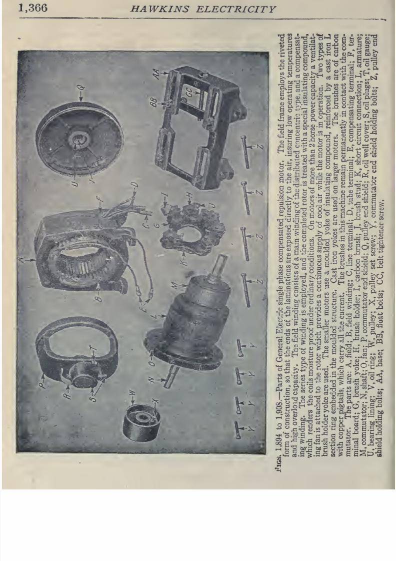
8/20/2019 electrical guide 5.pdf
http://slidepdf.com/reader/full/electrical-guide-5pdf 112/343
1,366
HAWKINS
ELECTRICITY
^.
a
S'^
9.
o
5
^
^
bcd-^
a;
^
E^.S
Vh
2
8
2o.S
Sr^^
S
9<^'r^
^ fe
-Q <y
+3
So
S
°
rt
&
qO
„, c J2 S
-
M
•-
0)13
5
R
G
S
lU
--O
:s
«j
tJ -,
C
?:
ih
„,
«
>>,-5-2
=«•-
Srrt
G-Q
M;S
2
oti
O
'^jsr-i-'^
to
Omti-t
C
^
&Plii-=io|lii
'^'
'^
~
—
,^
G
S S:
Qj
o
&
c
3
^
aj
«itc-^
E^rJj^
Wi 2'^Or3aJ<U-^„*:3y5,
J.
^^^.S
go
62:=i'^_S„*
m
2 S'^ &
p.:a
S'B
^i:
^>P=^
••S^^XI <U^J3^
O.
..-Mo
*^
^T3
oj.s
o
iH
a^: o
E.s
o
r-Tc^
m:s
Mg
o.^
;:i.S
-
.-^
o
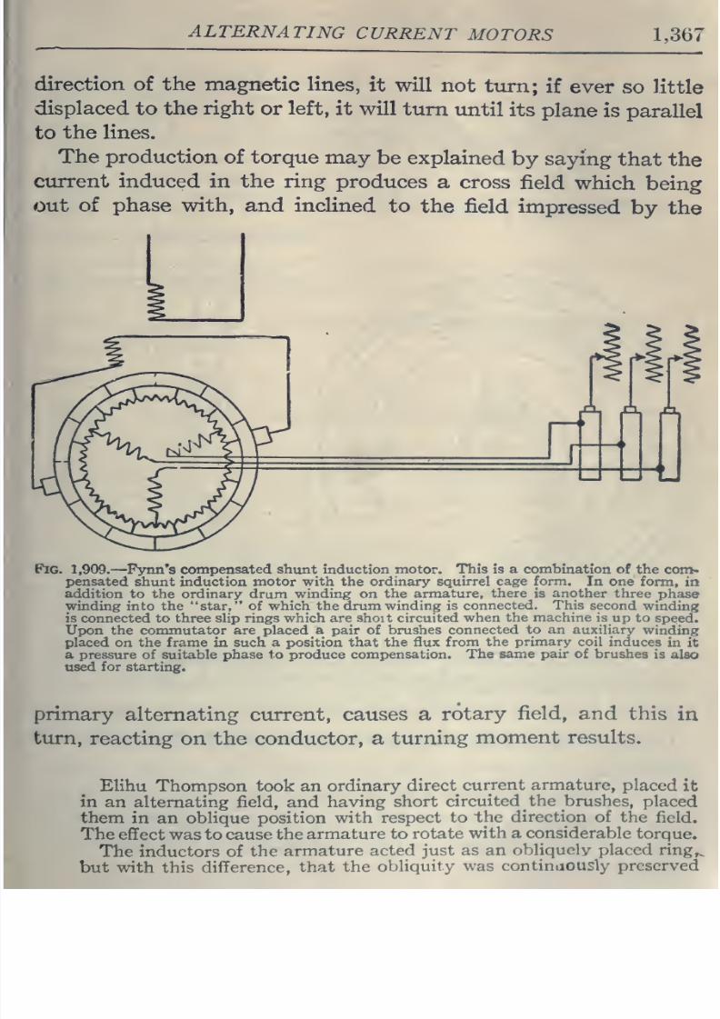
8/20/2019 electrical guide 5.pdf
http://slidepdf.com/reader/full/electrical-guide-5pdf 113/343
ALTERNATING
CURRENT
MOTORS
1,367
direction
of the magnetic
lines,
it
will
not
turn;
if
ever
so little
displaced
to the
right
or
left,
it will
turn
until
its
plane
is
parallel
to
the lines.
The
production
of
torque
may
be
explained
by
saying
that
the
current induced
in
the ring
produces
a cross
field
which
being
out
of phase with, and
inclined
to
the
field
impressed
by the
Fig. 1,909.
—
Pynn's
compensated shunt induction motor.
This is
a combination
of
the
com-
pensated
shunt induction
motor with
the
ordinary
squirrel cage form.
In
one
form,
in
addition
to
the ordinary
drum
winding
on
the armature,
there
is
another
three
phase
winding
into
the star,
of
which
the drum winding
is
connected. This
second
winding
is
connected
to
three
sUp
rings
which
are shoit
circuited
when
the
machine
is
up
to
speed.
Upon the commutator
are placed a pair of
brushes
connected
to
an
auxiliary
winding
placed
on
the
frame
in
such
a position that
the
flux
from
the
primary
coil induces
in
it
a
pressure
of suitable phase
to
produce
compensation. The
same
pair of brushes
is
also
used
for
starting.
primary
alternating current,
causes a
rotary
field,
and
this
in
turn,
reacting
on
the conductor,
a
turning
moment results.
Elihu
Thompson
took
an
ordinary
direct
current
armature,
placed
it
in
an alternating field,
and
haying
short
circuited
the brushes,
placed
them
in an
oblique
position
with
respect to
the
direction
of
the
field.
The
efifect was to
cause
the
armature
to
rotate
with
a
considerable
torque.
The
inductors
of
the
armature
acted
just
as an
obliquely placed ring^
but
with
this difference,
that
the
obliquity
was
continaously preserved
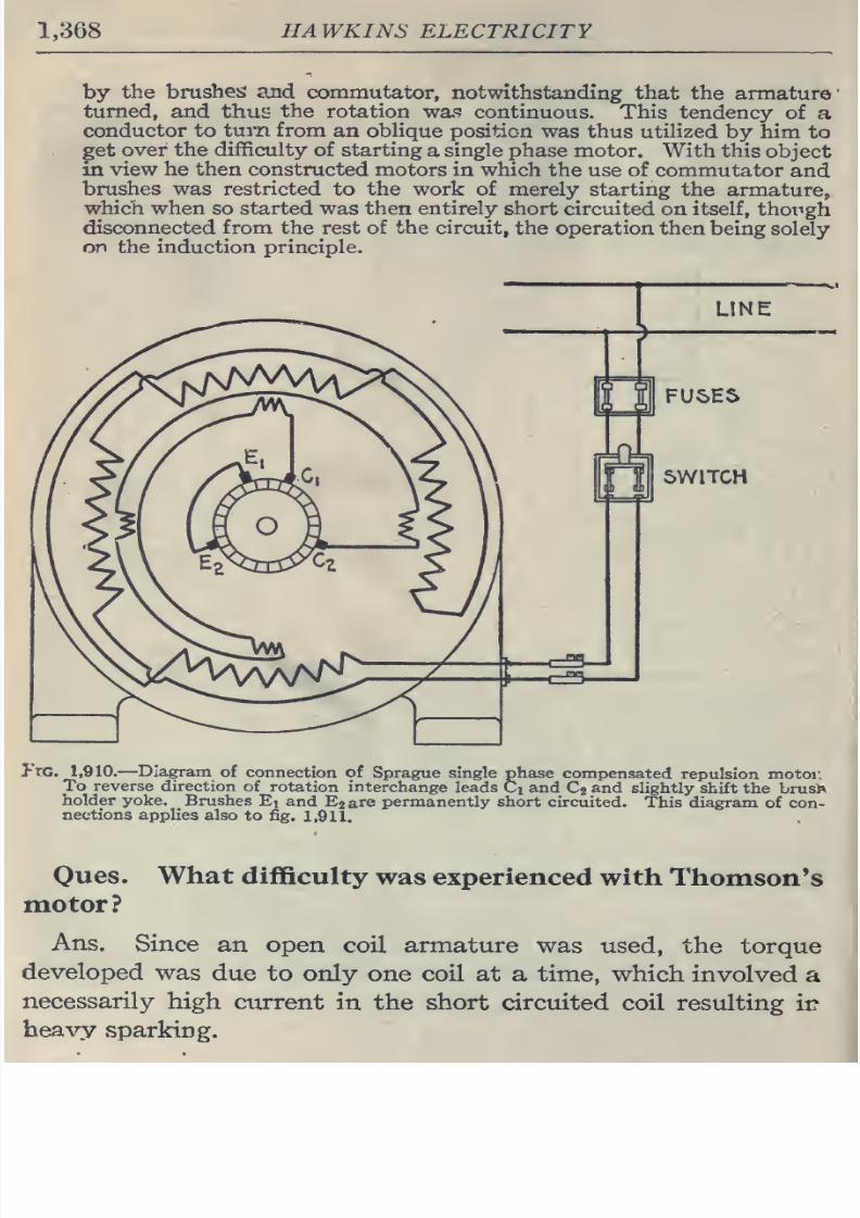
8/20/2019 electrical guide 5.pdf
http://slidepdf.com/reader/full/electrical-guide-5pdf 114/343
1,368
HAWKINS
ELECTRICITY
by
the
brushes
and
commutator,
notwithstanding
that
the
armature'
turned,
and
thu^
the
rotation was
continuous.
This tendency
of
a
conductor
to
turn
from
an oblique
position
was
thus
utilized
by
him
to
get
over the
difficulty
of starting
a
single
phase
motor.
With this
object
in
view
he
then constructed
motors in
which the
use of
commutator
and
brushes
was
restricted
to
the
work
of
merely
starting
the
armature,
which
when
so started
was
then entirely
short
circuited
on
itself,
though
disconnected
from
the rest
of
the
circuit,
the
operation
then
being
solely
on
the
induction
principle.
J-i:G. 1,910.
—
Diagram
of
connection
of
Sprague single
phase
compensated
repulsion
motor
To
reverse
direction
of
rotation
interchange
leads
Ci
and
Cg
and
slightly shift
the
brusi^
holder
yoke.
Brushes
Et
and
Eg
are
permanently short
circuited.
This diagram
of
con-
nections applies
also
to
fig.
1,911.
Ones,
motor?
What
difficulty
was experienced
with
Thomson's
Ans.
Since
an
open
coil
armature
was
used,
the
torque
developed
was
due
to
only
one
coil
at
a
time,
which
involved
a
necessarily
high
current
in
the short
circuited
coil
resulting
ii?
heavy
sparking.
8/20/2019 electrical guide 5.pdf
http://slidepdf.com/reader/full/electrical-guide-5pdf 115/343
ALTERNATING
CURRENT MOTORS
1,369
Oues.
How
was
this
remedied?
Ans.
By
the
use
of
closed
coil
armatures
in
later
construction
Oues.
Did
this
effectually
stop
sparking?
Ans.
No.
-
Oues.
What
other
means
is
employed
in
modern de-
signs
to reduce
sparking?
Ans.
Compensation and the use of
a
distributed
field
winding,
high
resistance connectors,
high
resistance brushes,
etc.
Oues.
What are
the names
of
the
two
classes of repul-
sion
motor?
Ans.
The
simple
and
the
compensated types.
Oues.
Describe
a
simple
repulsion
motor.
Ans.
It
consists
essentially
of
an
armature,
commutator
and
field
magnets.
The
armature
is
wound
exactly like a direct
current
armature, and
the
windings
are connected
to
a
com-
mutator.
The
carbon
brushes
which
rest
on
this
commutator
are
not
connected
to the outside line, however, but are
all
con-
nected
together
through
heavy
short circuiting
connectors.
The brushes
are
placed about
60°
or
70°
from
the neutral axis.
The
field
is
wound
exactly
like
that
of
the
usual
induction
motor.
Oues.
What is the
action
of
this
type
of
motor?
Ans.
If
nothing
be
done to
prevent, the
motor
will
increase
in
speed
at no load until
the
armature bursts,
just as
it
will
in
a
series
direct
current
motor.
Oues.
What
provision
is
made
to
avoid
this
danger?
Ans.
A governor
is usually mounted
on
the
armature
which
short
circuits
the
windings,
after
the
motor
has
been
started.
The
motor
then
runs
as
a
sqioirrel
cage induction
motor.
As
a
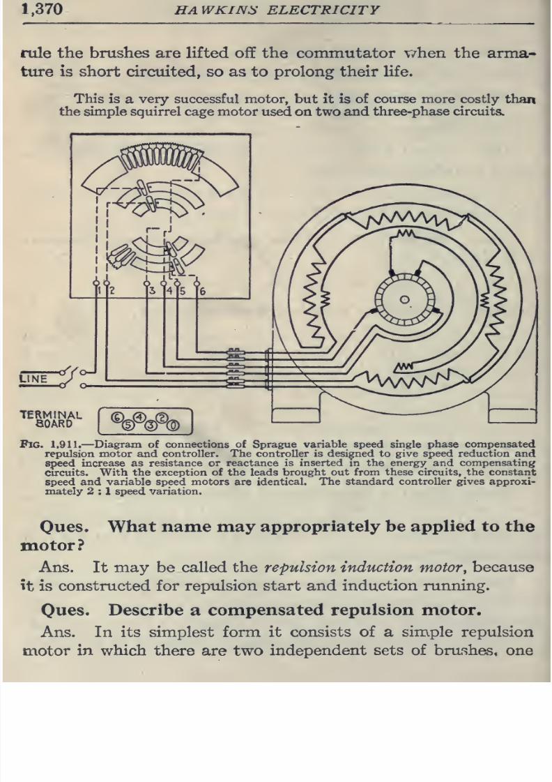
8/20/2019 electrical guide 5.pdf
http://slidepdf.com/reader/full/electrical-guide-5pdf 116/343
1.370
HAWKINS
ELECTRICITY
rule
the
brushes are lifted
off the
commutator
\7hen
the
arma-
ture
is short circuited,
so
as
to
prolong their life.
This
is
a
very
successful
motor,
but
it
is
of
course more
costly
than
the simple
squirrel
cage
motor
used
on two
and
three-phase
circuits.
#1%\
TERMINAL
aOARD
Fig.
1,911.
—
Diagram of
connections of
Sprague
variable
speed
single
phase compensated
repulsion motor
and
controller.
The controller
is
designed
to
give
speed
reduction
and
speed increase as
resistance or reactance
is
inserted
in
the
energy and compensating
cu-cuits.
With the
exception
of
the leads
brought out
from
these circuits, the constant
speed
and variable speed motors
are
identical.
The
standard
controller
gives
approxi-
mately
2
:
1
speed variation.
Oues.
What name may
appropriately
be
applied to
the
motor?
Ans.
It
may
be
called
the
repulsion induction motor
^
because
it
is
constructed for
reptdsion
start and induction running.
Oues.
Describe
a
compensated
repulsion
motor.
Ans. In
its simplest
form
it
consists of a simple
repulsion
motor
in
which
there
are
two
independent
sets of
brushes,
one
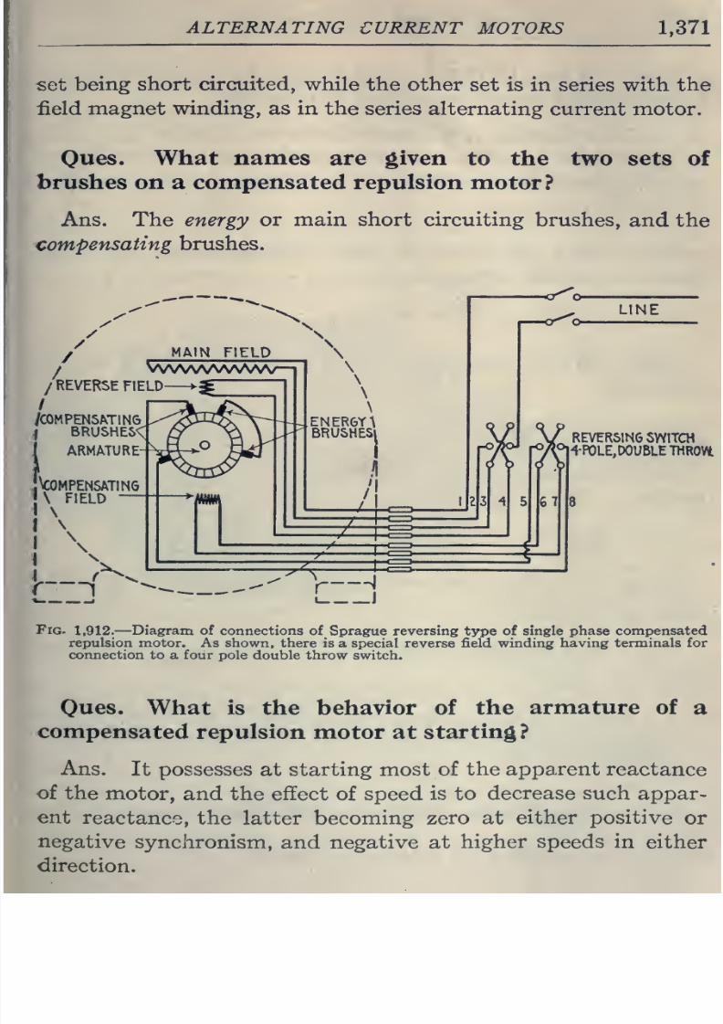
8/20/2019 electrical guide 5.pdf
http://slidepdf.com/reader/full/electrical-guide-5pdf 117/343
ALTERNATING
CURRENT
MOTORS
1,371
set
being
short
circuited, while
the
other
set
is in
series
with
the
field
magnet
winding,
as
in the
series
alternating
current
motor.
Ones.
What
names
are
given
to
the
two
sets of
brushes
on
a
compensated
repulsion
motor?
Ans. The energy
or main
short
circuiting
brushes,
and
the
compensating
brushes.
/REVERSE
FIELD
/
/COMPENSATING
iBRUSHES<\
ARMATURE
-^COMPENSATING
\
FIELD
—
^—
i'
K.
,
REVERSING
SWITCH
r7Vl+P0LE,DOUBLE
THROVt
Fig-
1,912.
—
Diagram of connections
of
Sprague reversing
type
of
single
phase
compensated
repulsion
motor.
As
shown, there
is
a
special reverse field winding
having
terminals
for
connection
to a
four pole
double throw switch.
Ques.
What is the behavior
of
the
armature of
a
compensated
repulsion motor
at
starting?
Ans.
It possesses
at
starting most of
the
apparent
reactance
of
the
motor,
and the effect
of
speed
is to
decrease such
appar-
ent
reactance,
the
latter
becoming zero at
either positive
or
negative
synchronism,
and negative
at
higher
speeds
in
either
direction.
8/20/2019 electrical guide 5.pdf
http://slidepdf.com/reader/full/electrical-guide-5pdf 118/343
1,372
HAWKINS
ELECTRICITY
Ques. What is the nature
of
the
field
circuit
of
the
compensated
repulsion
motor
at starting?
Ans.
At
starting it
is
practically
non-inductive,
the
effect
of
speed
being
to
introduce
a
spurious
resistance
which
in-
creases directly with
the
speed, and
becomes
negative
when
the
speed
is
reversed.
Ques.
For what use
is the
compensated
repulsion
motor especially
adapted
?
Ans.
For
light
railroad
service.
Ques.
When
employed
thus
what is
the
method
of
control?
Ans.
A
series
transformer is used
in
the
field
circuit.
Ones.
What
frequencies
are
employed
with
this
motor?
Ans.
25
to
60,
the
preferred
frequency being
40.
Ques.
To
what
important
use
is
the
repulsion
prin-
ciple
put?
Ans.
It
is sometimes
employed
for starting
on
single
phase
induction
motors.
In
this
method, after
bringing
the
motor up
to
speed,
the
winding
is
then
short circuited
upon
itself, and the
motor
then operates
on
the
induction
principle.
i
Ques.
What
name
is
given
to
this
type of
motor?
Ans.
It
is
called
the
repulsion
induction motor.
I
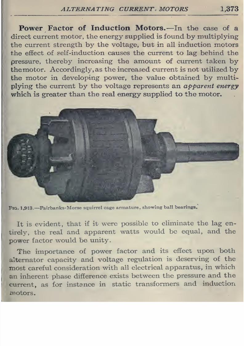
8/20/2019 electrical guide 5.pdf
http://slidepdf.com/reader/full/electrical-guide-5pdf 119/343
ALTERNATING CURRENT,
MOTORS
1.373
Power
Factor
of
Induction Motors.
—
In
the case
of
a
direct
current
motor, the energy
suppHed
is found
by
multiplying
the
current
strength by
the
voltage, but
in
all
induction motors
the
effect
of
self-induction
causes
the
current to
lag
behind
the
pressure,
thereby
increasing the
amount
of
current
taken
by
themotor.
Accordingly,
as
the increased current
is not
utilized
by
the
motor
in
developing
power, the
value
obtained
by
multi-
plying
the current by
the
voltage represents
an
apparent energy
which is greater
than
the
real
energy
supplied
to the
motor.
Fig.
1,913.
—
^Fairbanks-Morse
squirrel
cage
armature,
showing
ball bearings.
It
is
evident,
that
if
it
were
possible
to
eliminate the
lag
en-
tirely,
the
real
and
apparent
watts
would
be
equal, and
the
power
factor
would
be
unity.
The
importance
of power
factor
and
its
effect
upon
both
alternator
capacity
and voltage
regulation
is deserving
of the
most
careful
consideration
with
all
electrical
apparatus,
in
which
an inherent
phase
difference
exists
between
the
pressure
and
the
current,
as
for
instance
in
static
transformers
and
induction
ipotors.
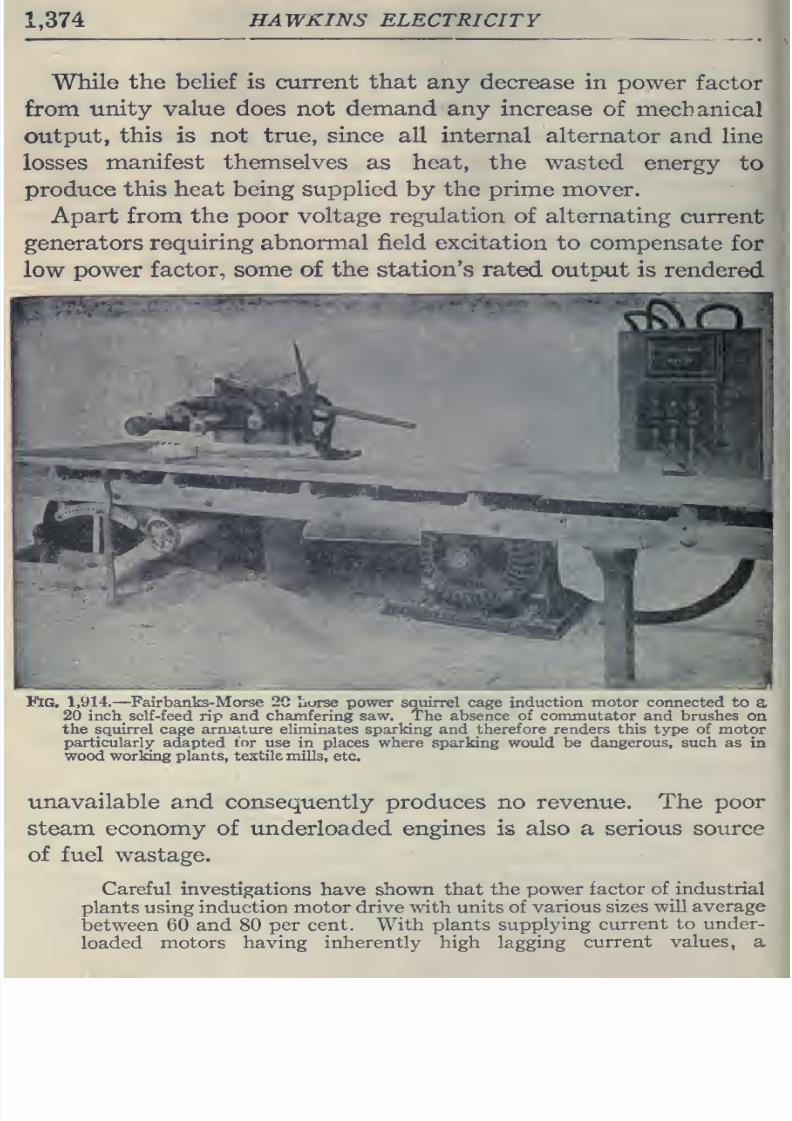
8/20/2019 electrical guide 5.pdf
http://slidepdf.com/reader/full/electrical-guide-5pdf 120/343
1,374
HAWKINS
ELECTRICITY
While
the beHef is
current
that
any
decrease in
power
factor
from
unity
value
does not
demand
any increase
of
mechanical
output,
this
is
not
true, since
all internal
alternator
and line
losses
manifest
themselves
as
heat,
the
wasted
energy
to
produce
this heat being
supplied
by
the prime
mover.
Apart from
the poor
voltage
regulation
of
alternating
current
generators
requiring abnormal
field
excitation
to compensate
for
low
power
factor, some of the station's
rated
output
is
rendered
Fig.
1,914.
—Fairbanks-
Morse
2C horse power squirrel
cage
induction motor
connected to
a
20
inch_ self-feed
rip
and
chamfering saw. The
absence of commutator
and brushes
on
the squirrel
cage
arrnature eliminates sparking and
therefore
renders this type of
motor
particularly adapted
tor
use
in places
where sparking
would be
dangerous, such as
in
wood worlong plants, textile mills,
etc.
unavailable
and consequently
produces
no
revenue.
The
poor
steam economy
of underloaded engines
is
also
a
serious
source
of
fuel
wastage.
Careful
investigations
have
shown
that
the
power
factor
of
industrial
plants using
induction motor drive
with
units of
various
sizes
will
average
between
60
and
80
per
cent.
With plants
supplying
current
to under-
loaded
motors having
inherently high
lagging
current
values, a
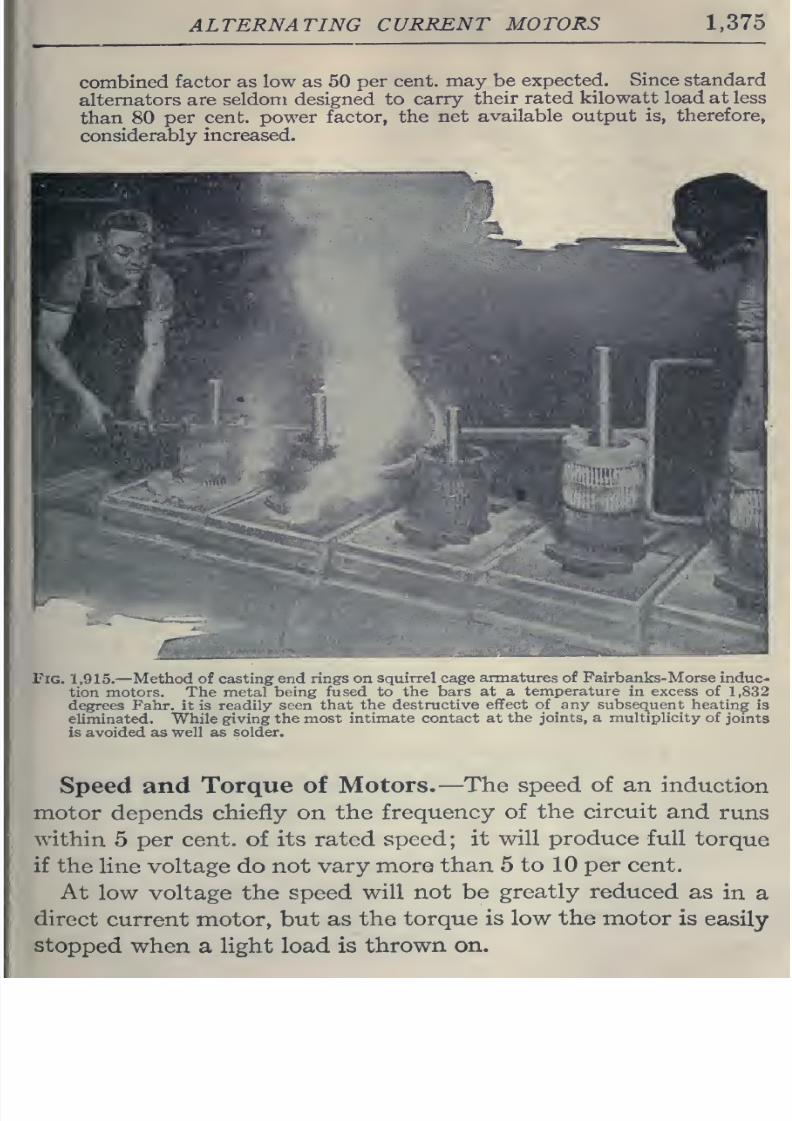
8/20/2019 electrical guide 5.pdf
http://slidepdf.com/reader/full/electrical-guide-5pdf 121/343
ALTERNATING
CURRENT
MOTORS 1,375
combined
factor as
low
as 50
per
cent,
may
be
expected.
Since standard
alternators
are seldom
designed to
carry
their
rated
kilowatt
load
at less
than
80
per cent,
power
factor,
the
net
available output
is, therefore,
considerably
increased.
JPlG.
1,915.
—
Method
ui
cuoiiiig, c:,d
:li;gs
on
Sfiuirrd
cage
annatures
of Fairbanks-Morse
induc-
tion
motors. The
metal
being
fused
to the
bars at
a
temperature
in
excess
of
1,832
degrees Fahr.
it
is
readily
seen
that
the
destructive
effect of
any
subsequent heating
is
eliminated. While giving
the
most
intimate
contact at
the
joints,
a multiplicity of
joints
is avoided as well as solder.
Speed and
Torque
of
Motors.
—The speed
of
an
induction
motor
depends
chiefly
on
the
frequency
of the
circuit
and
runs
within
5
per cent,
of its
rated
speed;
it
will produce full
torque
if the
line
voltage do not
vary
more
than
5
to 10
per
cent.
At
low voltage
the
speed
will
not be
greatly reduced
as
in
a
direct
current
motor,
but as the
torque is
low
the
motor
is
easily
stopped when
a
light
load
is
thrown
on.
8/20/2019 electrical guide 5.pdf
http://slidepdf.com/reader/full/electrical-guide-5pdf 122/343
1,376
HAWKINS
ELECTRICITY
The
current
taken
by
an
induction motor
from a constant
pressure
line
varies
with
the
speed as
in
a direct current motor.
When a
load
is
thrown
on, the
speed
is reduced
correspondingly
and
as the self-induction or reactance
is
diminished,
more
current
circulates
in
the
squirrel cage
winding, which
in
turn
reacts on
the field coils in
a
similar
manner and
more
current
flows in
them
from
the
line.
In this manner the
motor
auto-
matically
takes
current from
the
line proportional
to
the
load
and
maintains
a
nearly
constant
speed.
The
so-called
constant speed motors require slight variations
in
speed
to
automatically
take
current
from
the
line
when
the
load
varies.
Induction
motors
vary
in
speed from 5 to 10 per cent., while
synchronous
motors
vary
but
a fraction
of one per cent.
Single
phase
motors
to render efficient service
must
be able,
where
requisite,
to
develop sufficient turning moment
or torque
to
accelerate, from
standstill,
loads
possessing
large
inertia or
excessive static friction
;
for
example,
meat
choppers
and
grinders,
sugar
or laundry centrifugals; heavy
punch
presses; group
driven
machines
running
from countershafts
with
possibly
over
taut
belting,
poor
alignment,
lubrication,
etc.
8/20/2019 electrical guide 5.pdf
http://slidepdf.com/reader/full/electrical-guide-5pdf 123/343
TRANSFORMERS
1,377
CHAPTER
LII
TRANSFORMERS
The
developments in
the
field of electrical
engineering
which
have rendered
feasible
the
transmission
of
high
pressure
currents
over
long
distances,
together with the
reliability
and
efficiency
of
modern
generating
units,
have
resulted
in
notable
economies in
the
generation
and
distribution
of
electric
current.
This
has
been
accomplished largely
by
the
use
of
distant
water
power or the centralization
of the
generating
plants
of
a
large
territory in
a
single power
station.
The transformer is one
of
the
essential
factors
in
effecting
the
economical distribution
of
electric
energy,
and
may
be
defined
as
an
apparatus
used
for
changing
the
voltage a
id
current
of
an
alternating
circuit. A
transformer
consists
essentially
of:
1.
A
primary winding;
2.
A
secondary winding;
3. An
iron
core.
Basic
Principles.
—If a
current
be
passed
through
a
coil
of
wire
encircling
a
bar
of
soft
iron
the
iron
will
become
a
magnet;
when
the
current
is
discontinued
the
bar
loses
its
magnetization.
Conversely:
If a
bar of iron
carrying
a
coil
of wire
be
mag-
netized
in
a
direction
at
right
angles
to
the
plane
of
the
coil
a
momentary
electric
pressure
will
be
induced
in
the
wire;
if
the
current
be reversed, another momentary
pressure
will
be
induced
in
the
opposite
direction in
the
coil.
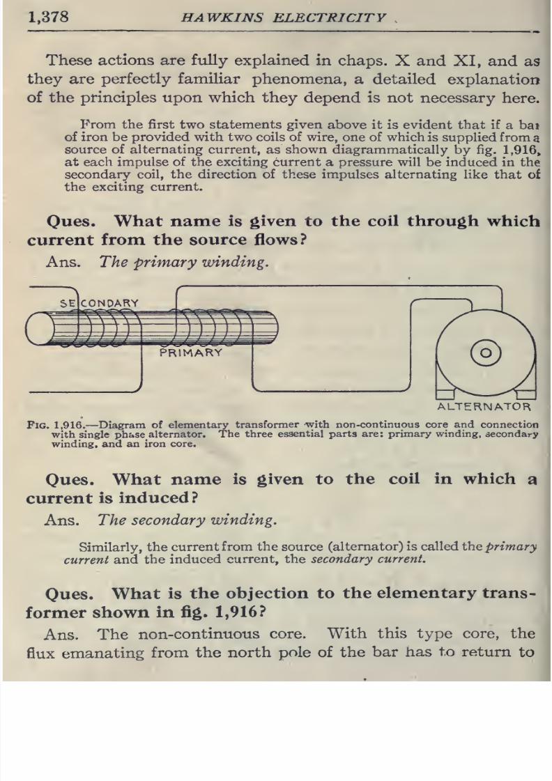
8/20/2019 electrical guide 5.pdf
http://slidepdf.com/reader/full/electrical-guide-5pdf 124/343
1,378
HAWKINS
ELECTRICITY
These
actions
are
fully
explained
in
chaps.
X
and
XI,
and
as
they are
perfectly
familiar
phenomena,
a
detailed
explanation
of the
principles
upon
which
they
depend
is
not necessary
here.
From
the
first
two
statements
given
above it is
evident that
if
a bai
of iron
be
provided
with two coils of
wire,
one of
which
is supplied from
a
source of
alternating current,
as
shown
diagrammatically
by fig.
1,916»
at
each
impulse
of the exciting current
a
pressure
will
be
induced in
the
secondary coil, the direction
of
these impulses
alternating
like that
of
the
exciting current.
Ones.
What
name is
given
to
ttie
coil
tlirougli
which
current
from
the
source
flows?
Ans.
The
primary winding.
ALTERNATOR
Fig.
1,916.
—Diagram
of elementary
transformer
with non-continuous
core
and connection
with
single
phase
alternator.
The
three
essential
parts are:
primary
winding,
secondary
winding,
and an
iron
core.
Oues.
What
name
is
given
to
the
coil
in
which
a
current
is
induced ?
Ans.
The
secondary
winding.
Similarly,
the
current
from
the source
(alternator) is called the primary
current
and
the induced
current, the
secondary
current.
Oues.
What
is
the
objection
to
the
elementary
trans-
former
shown
in
fig.
1,916?
Ans.
The
non-continuous
core.
With
this
type
core,
the
flux
emanating
from the
north
pole
of
the
bar
has
to
return
to
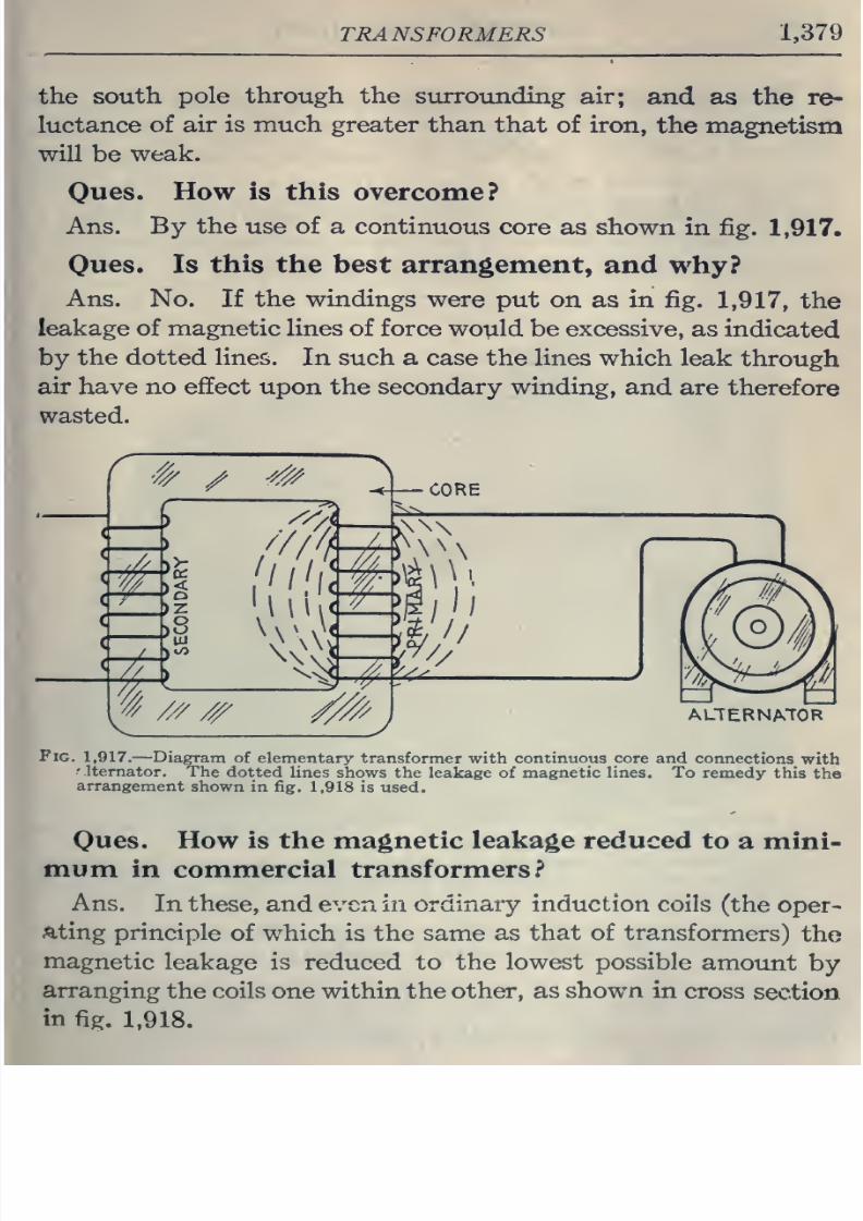
8/20/2019 electrical guide 5.pdf
http://slidepdf.com/reader/full/electrical-guide-5pdf 125/343
TRANSFORMERS
1,379
the
south
pole through
the surrounding
air;
and
as the
re-
luctance
of
air
is much
greater than
that
of
iron,
the
magnetism
will
be
weak.
Oues.
How
is
this
overcome?
Ans.
By
the
use of a
continuous
core
as
shown
in
fig.
1,917.
Ones.
Is
this the
best arrangement,
and
why?
Ans.
No.
If
the
windings
were
put
on
as
in
fig.
1,917,
the
leakage
of magnetic lines
of
force
would be
excessive,
as
indicated
by
the
dotted
lines.
In such
a
case
the lines
which
leak
through
air have no
effect upon
the
secondary
winding,
and are
therefore
wasted.
ALTERNATOB
Fig.
1,917.
—
Diagram
of elementary transformer
with
continuous
core and
connections
with
'
Itemator.
The dotted
lines
shows the
leakage
of
magnetic
lines.
To
remedy
this
the
arrangement
shown
in fig.
1,918 is used.
Oues.
How
is the
magnetic
leakage
reduced
to
a mini-
mum in
commercial
transformers?
Ans.
In
these,
and even
in
ordinary
induction
coils
(the
oper-
ating
principle of
which
is
the
same
as
that
of
transformers)
the
magnetic
leakage
is reduced to the
lowest possible
amount
by
arranging
the
coils
one within the
other, as
shown
in
cross
section
in
fig.
1,918.
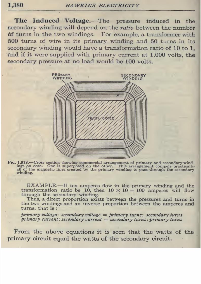
8/20/2019 electrical guide 5.pdf
http://slidepdf.com/reader/full/electrical-guide-5pdf 126/343
1,380
HAWKINS
ELECTRICITY
The
Induced Voltage.
—
The
pressure
induced in
the
secondary
winding
will
depend
on the
ratio
between
the
number
of
tiims in
the two windings.
For
example,
a
transformer
with
500
turns
of
wire
in
its
primary
winding
and
50
turns
in
its
secondary winding
would
have
a transformation
ratio
of 10
to
1,
and
if
it
were
supplied with primary
current
at
1,000
volts,
the
secondary
pressure
at
no
load
would
be 100
volts.
Fig.
1,918.
—
Cross
section
showing
commercial
arrangement of
primary
and secondary wind
ings on
core.
One
is
superposed
on the
other.
This
arrangement
compels
practically
all of the
magnetic
lines
created by
the primary
winding
to
pass through
the
secondary
winding.
EXAMPLE.
—
If
ten amperes
flow in the primary
winding and the
transformation
ratio
be
10,
then
10
X
10
=
100 amperes will
flow
through the
secondary winding.
Thus,
a direct
proportion
exists
between
the
pressures
and
turns in
the two
windings
and an inverse
proportion
between
the
amperes
and
turns, that
is :
primary
voltage:
secondary
voltage
=
primary
turns:
secondary
turns
primary
current:
secondary
current
=
secondary
turns:
primary turns
From
the
above
equations
it is
seen
that
the
watts
of
the
primary
circuit
equal
the
watts of
the secondary
circuit.
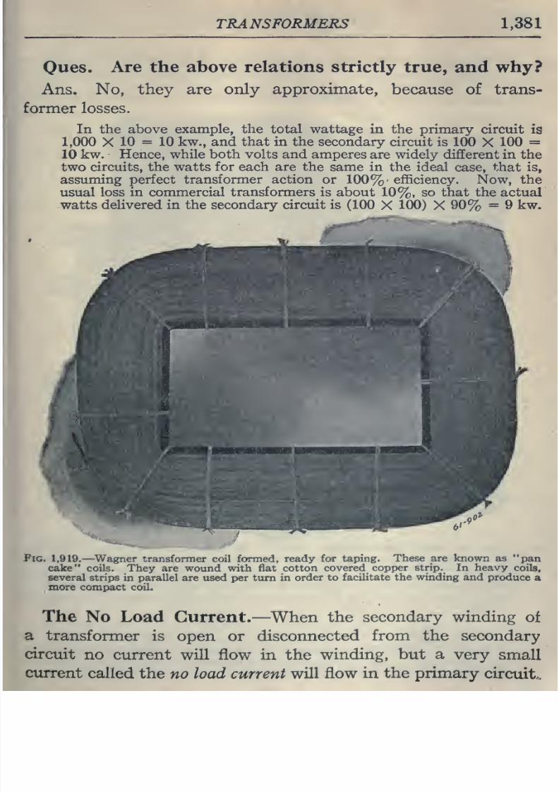
8/20/2019 electrical guide 5.pdf
http://slidepdf.com/reader/full/electrical-guide-5pdf 127/343
TRANSFORMERS
1,381
Ques.
Are
the
above
relations
strictly
true,
and
why?
Ans. No,
they are
only approximate,
because
of
trans-
former losses.
In
the
above
example,
the
total wattage
in
the
primary
circuit
is
1,000
X
10
=
10
kw.,
and
that
in
the
secondary
circuit
is 100
X
100
=
10 kw. Hence,
while both volts
and
amperes
are
widely
different
in
the
two
circuits,
the
watts
for
each are
the
same in the
ideal
case,
that is,
assuming
perfect
transformer action
or 100%'
efficiency.
Now, the
usual loss
in
commercial
transformers
is
about
10%,
so
that the
actual
watts
delivered in
the
secondary
circuit
is
(100
X
100)
X
90%
=
9
kw.
-m
f%.>«*t*''
«.^
'^mgrjn
I
Fig. 1,919.
—
^Wagner
transformer
coil formed, ready
for
taping.
These
are
known
as
pan
cake
coils. They
are wound with
flat
cotton
covered
copper
strip.
In
heavy
coils,
several
strips in parallel
are
used
per
turn
in order
to
facilitate the winding and
produce
a
more compact coil.
The
No
Load
Current.
—
When
the
secondary winding
of
a
transformer
is
open
or
disconnected
from
the
secondary
circuit
no
current will flow in the
winding,
but a
very
small
current
called
the
no
load
current
will
flow in
the
primary
circuit,.
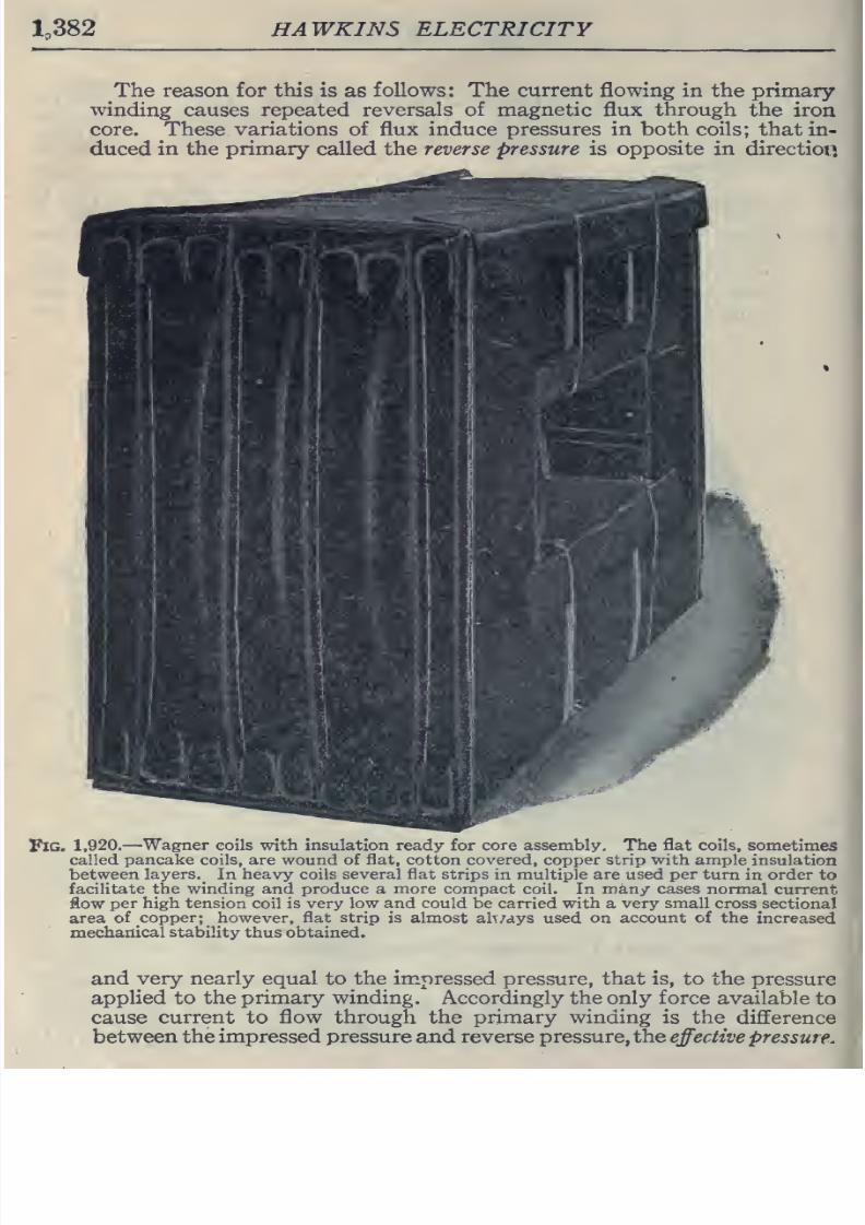
8/20/2019 electrical guide 5.pdf
http://slidepdf.com/reader/full/electrical-guide-5pdf 128/343
lo382
HAWKINS ELECTRICITY
The reason for
this
is
as
follows:
The
current
flowing
in
the
primary
winding
causes repeated
reversals
of
magnetic
flux through the
iron
core. These
variations
of
flux
induce
pressures
in
both coils;
that
in-
duced
in
the
primary
called the
reverse
pressure is
opposite
in direction
Fig.
1,920.—
Wagner
eoils
with
insulation
ready for
core assembly.
The
flat coils,
sometimes
called
pancake
coils, are wound
of
flat,
cotton
covered, copper strip with ample
insulation
between
layers.
_
In
heavy coils several flat
strips
in multiple
are used per
turn
in
order
to
facilitate
the
winding and
produce
a more
compact
coil. In
many
cases
normal
current
flow
per high
tension
coil is
very
low and
could
be
carried
with
a
very
small
cross
sectional
area
of
copper;
however,
flat strip
is
almost
ah
/ays
used
on account
of
the
increased
mechailical
stability
thus
obtained.
and
very nearly equal
to
the
impressed
pressure,
that
is,
to the
pressure
applied
to
the
primary
winding.
Accordingly
the only
force
available
to
cause
current to
flow through
the
primary
winding
is the
difference
between the impressed
pressure and
reverse pressure,
the
effective
pressure.
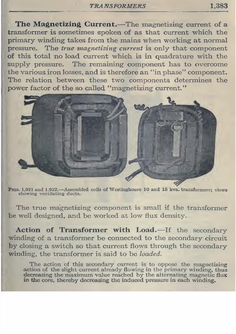
8/20/2019 electrical guide 5.pdf
http://slidepdf.com/reader/full/electrical-guide-5pdf 129/343
TRANSFORMERS
1,383
The
Magnetizing
Current.—
The
magnetizing
current
of
a
transformer
is
sometimes
spoken
of
as
that
current
which
the
primary
winding takes
from the
mains
when
working
at
normal
pressure.
The
true
magnetizing
current
is
only
that
component
of
this
total
no load current
which
is
in
quadrature
with the
supply
pressure.
The remaining
component
has
to
overcome
the
various
iron
losses,
and
is
therefore
an
in phase
component.
The
relation between
these
two
components
determines the
power
factor
of
the
so
called
magnetizing current.
Pigs. 1,921 and
1,922.
—
Assembled coils
of
Wcstinghouse
10
and 15
kva.
transformers;
views
showing
ventilating
ducts.
The
true magnetizing component
is small
if
the
transformer
be
well
designed,
and
be
worked at
low
flux
density.
Action
of
Transformer
with
Load.
—
If
the
secondary
winding
of a
transformer
be
connected
to the
secondary
circuit
by
closing
a
switch
so
that
current
flows
through
the
secondary
winding,
the
transformer
is
said
to
be
loaded.
The
action
of
this secondary
current is^ to
oppose
the
magnetizing
action
of
the slight current
already
flowing
in the primary
winding,
thus
decreasing
the maximum value reached
by
the
alternating
magnetic
flux
in
the
core,
thereby decreasing
the
induced
pressure
in
each
winding.
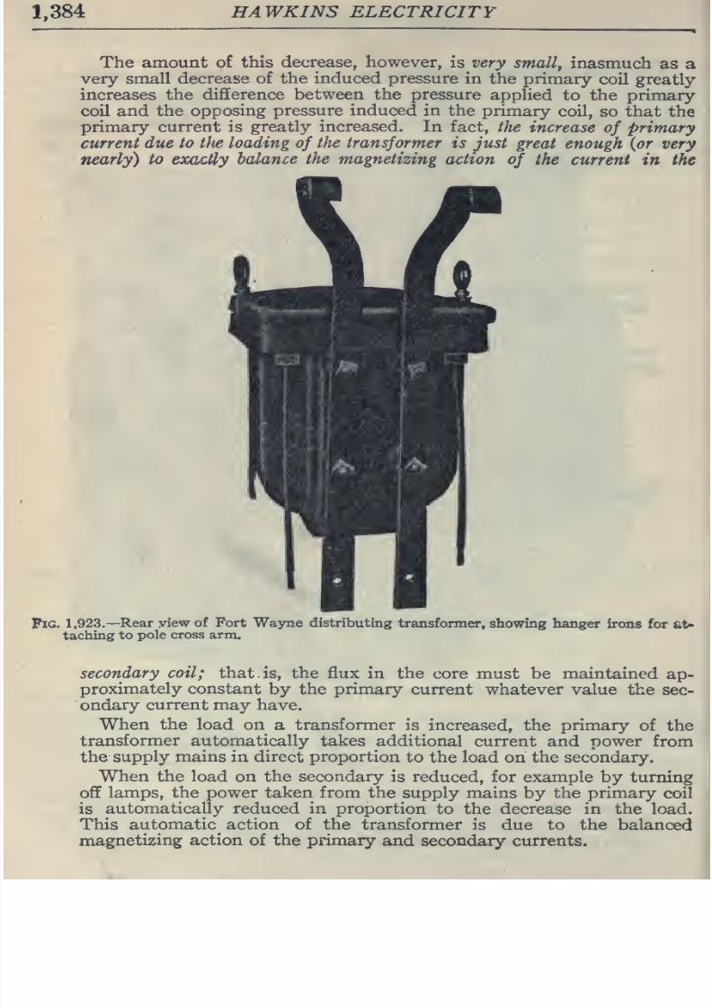
8/20/2019 electrical guide 5.pdf
http://slidepdf.com/reader/full/electrical-guide-5pdf 130/343
1,384
HAWKINS ELECTRICITY
The
amount
of this
decrease, however,
is very
small,
inasmuch
as
a
very
small
decrease of
the
induced pressure
in
the
primary
coil
greatly
increases the
difference
between the pressure
applied
to
the
primary
coil
and the
opposing
pressure
induced
in
the
primary
coil,
so
that
the
primary
current
is
greatly
increased.
In fact,
the
increase
of
primary
current due
to
the
loading
of
the
transformer
is just
great
enough {or
very
nearly)
to
eocactly
balance
the
magnetizing
action
of
the
current
in
the
Pig.
1,923.—Rear view
of Fort
Wayne distributing
transformer,
showing
hanger
irons
for
at-
taching
to
pole
cross arm.
secondary
coil;
that.
is, the flux
in
the
core
must be
maintained
ap-
proximately constant
by
the
primary
current
whatever
value
the
sec-
ondary
current
may have.
When
the
load
on a
transformer
is increased, the
primary
of
the
transformer
automatically
takes additional
current
and
power
from
the
supply
mains
in direct
proportion
to
the
load
on
the
secondary.
When
the
load
on
the
secondary
is
reduced,
for
example
by
turning
off
lamps,
the
power
taken
from
the
supply
mains
by the
primary
coil
is
automatically reduced in proportion
to
the
decrease
in
the
load.
This
automatic
action
of
the
transformer
is due to
the
balanced
magnetizing
action
of
the
primary
and secondary
currents.
8/20/2019 electrical guide 5.pdf
http://slidepdf.com/reader/full/electrical-guide-5pdf 131/343
TRANSFORMERS
1,385
Classification
of
Transformers.—As
in
the
case
of
motors,
the
great
variety of
transformer
makes
it
necessary
that
a
classification,
to
be
comprehensive,
must
be made
from
several
points
of
view,
as:
1.
With
respect
to the
transformation,
as
a.
Step up
transformers;
b.
Step
down
transformers.
2.
With respect
to the arrangement
of
the
coils
and
magnetic
circuit,
as
a.
Core
transformers;
h.
Shell
transformers;
c.
Combined
core and
shell
transformers.
3.
With respect to
the
kind of circuit
they are to
be used
on,
as
a.
Single
phase
transformers
h.
Polyphase
transformers.
4.
With respect to
the
method
employed in cooling,
as
a.
Dry
transformers;
6.
Air
cooled transformers
{
Fo^S'SS^.'Wafrbla^,
c.
Oil
cooled
transformers;
d.
Water
cooled transformers.
5.
With respect
to
the
nature
of
their
output,
as
a.
Constant
pressure
transformers;
h.
Constant
current
transformers;
c.
Current
transformers;
d.
Auto-transformers.
6.
With respect to
the
kind
of
service,
as
a.
Distributing;
b.
Power.
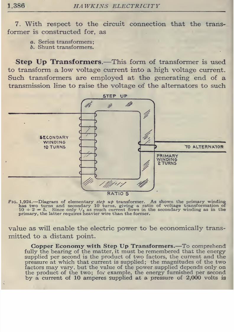
8/20/2019 electrical guide 5.pdf
http://slidepdf.com/reader/full/electrical-guide-5pdf 132/343
1,386
HAWKINS
ELECTRICITY
7.
With respect to
the
circuit connection
that
the
trans-
former
is
constructed
for,
as
a.
Series transformers;
b.
Shunt
transformers.
Step
Up
Transformers.
—
This foi-m of transformer
is
used
to
transform
a
low voltage
current into
a
high
voltage
current.
Such
transformers
are
employed
at
the generating
end
of
a
transmission line
to raise the
voltage of
the
alternators to
such
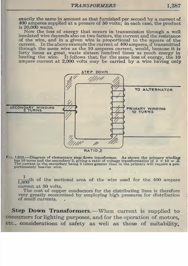
8/20/2019 electrical guide 5.pdf
http://slidepdf.com/reader/full/electrical-guide-5pdf 133/343
TRANSFORMERS
1,387
exactly the
same
in amount
as that furnished
per second
by
a current
of
400
amperes
supplied
at
a
presure
of
50
volts;
in
each
case, the
product
is
20,000
watts.
Now
the
loss
of
energy that
occurs in
transmission
through
a
well
insulated wire
depends also
on
two factors, the
current
and
the
resistance
of
the
wire,
and
in
a
given
wire
is
proportional
to
the
square
of
the
current.
In the
above
example
the
current
of
400
amperes,
if
transmitted
through
the same wire as the
10
amperes
current,
would,
because it
is
forty
times
as great, waste sixteen
hundred
times as
much
energy
in
heating
the wire. It
follows
that,
for
the
same
loss
of
energy,
the
10
ampere
current
at
2,000
volts may
be carried
by
a
wire having
only
6TEP
DOWN
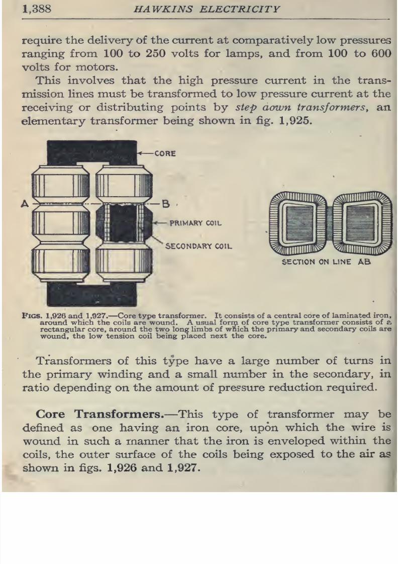
8/20/2019 electrical guide 5.pdf
http://slidepdf.com/reader/full/electrical-guide-5pdf 134/343
1,388
HAWKINS
ELECTRICITY
require
the delivery
of
the
current
at
comparatively
low pressures
ranging
from
100 to
250
volts
for
lamps,
and
from
100 to
600
volts
for
motors.
This
involves
that
the
high
pressure
current
in
the
trans-
mission
lines
must
be
transformed to low
pressure
current at the
receiving
or
distributing
points
by
step aown
transformers, an
elementary
transformer
being
shown
in
fig.
1,925.
CORE
PRIMARY
COIL
SECONDARY COIL
SECTION
ON
LINE
AB
Pigs.
1,926
and
1,927,
—
Core type
transformer.
It
consists of
a
central
core of laminated
iron,
around
which
the
coils are
wound.
A
usual
forrn
of
core
type
transformer consists
of
e,
rectangular
core, around
the
two
long
limbs of
which
the
primary and
secondary
coils
are
wound, the low
tension
coil being
placed next the core.
Transformers
of
this
type have
a large
number
of
turns
in
the
primary winding
and
a small
number in
the
secondary, in
ratio
depending on
the amount
of
pressure
reduction
required.
Core
Transformers.
—
This
type of
transformer
may
be
defined
as
one
having
an
iron
core,
upon
which
the
wire
is
wound
in such
a
manner that
the
iron
is
enveloped
within the
coils, the
outer
surface
of the
coils being exposed
to the
air
as
shown
in figs.
1,926
and
1,927.
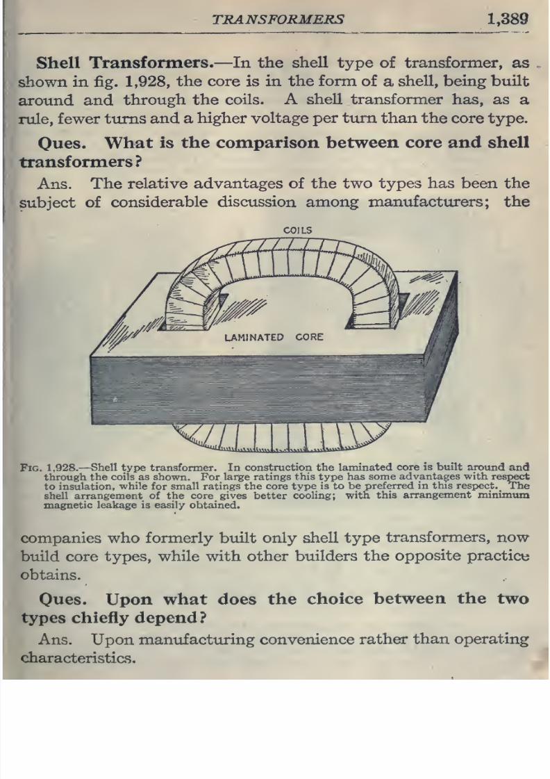
8/20/2019 electrical guide 5.pdf
http://slidepdf.com/reader/full/electrical-guide-5pdf 135/343
TRANSFORMERS
1,389
Shell
Transformers.
—
In
the
shell
type
of
transformer,
as
shown in fig.
1,928,
the
core
is
in the
form
of
a
shell,
being built
around and
through
the
coils.
A
shell transformer
has, as
a
rule,
fewer
turns
and
a
higher voltage
per
turn
than
the
core
type.
Oues.
What
is
the comparison between
core
and
shell
transformers?
Ans.
The
relative
advantages of the
two
types
has been the
subject
of
considerable
discussion
among
manufacturers; the
COILS
Fig.
1,928.—
Shell
type
transformer.
In
construction the laminated
core
is
built
around
and
through
the
coils
as
shown.
For
large
ratings
this
type
has
some
advantages with
respect
to
insulation,
while
for
small ratings
the
core
type
is
to
be
preferred
in this
respect.
The
shell
arrangement
of
the
core
gives
better
cooling;
with
this
arrangement
minimum
magnetic
leakage
is
easily
obtained.
companies
who
formerly
built
only shell
type
transformers,
now
build core
types, while
with
other
builders
the
opposite
practice
obtains.
Oues.
Upon
what
does the
choice
between
the
two
types
chiefly depend
?
Ans. Upon manufacturing
convenience
rather
than
operating
characteristics.
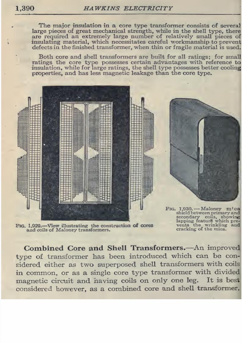
8/20/2019 electrical guide 5.pdf
http://slidepdf.com/reader/full/electrical-guide-5pdf 136/343
1,390
HAWKINS ELECTRICITY
The
major
insulation
in
a
core type transformer consists
of
several
large
pieces of great mechanical strength,
while
in the
shell type, there
are
required an
extremely large number of relatively
small pieces of
insulating
material, which necessitates
careful
workmanship
to
prevent
defects
in
the
finished transformer, when
thin
or fragile
material
is used.
Both core
and
shell
transformers
are
built for
all
ratings; for
small
ratings the
core
type
possesses
certain
advantages
with reference
to
insulation,
while
for
large ratings, the shell type possesses better cooling
properties,
and
has
less
magnetic leakage
than
the core
type.
Fig. 1,929.
—
^View
illustrating the construction
of
cores
and
coils
of
Maloney
transformers.
Fig.
1,930.
—
Maloney
m'ca
shieldbetween
primary
and
secondary
coils, showing
lapping
featurS
which
pre-
vents_
the
wrinkling
and
cracking
of the
mica.
Combined Core
and
Shell
Transformers.
—
An
improved
type
of
transformer has
been
introduced
which can
be
con-
sidered
either as
two
superposed
shell
transformers
with coils
in
common,
or
as
a
single core
type
transformer
with
divided
magnetic circuit
and
having
coils
on
only
one leg.
It is best
considered
however,
as
a
combined
core
and
shell
transformer.
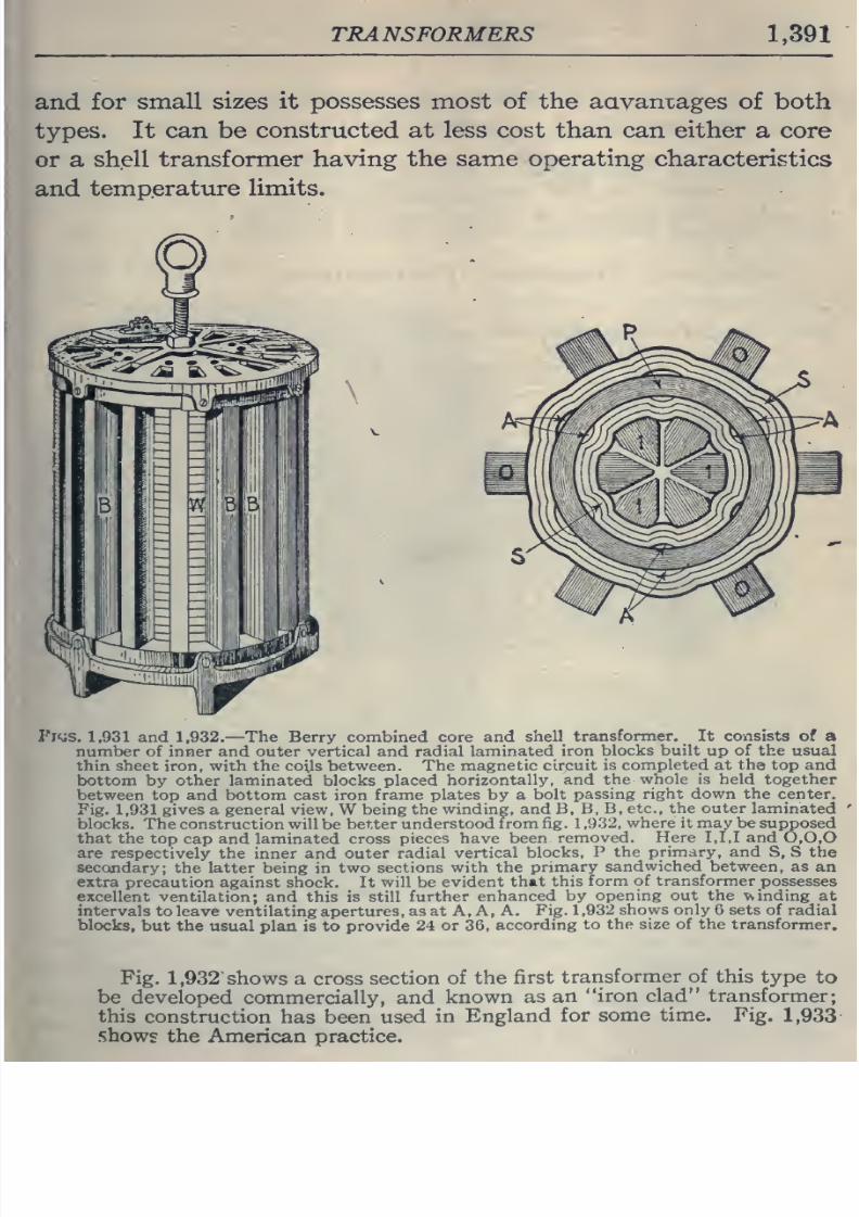
8/20/2019 electrical guide 5.pdf
http://slidepdf.com/reader/full/electrical-guide-5pdf 137/343
TRANSFORMERS
1,391
and
for
small
sizes
it possesses
most of
the aavamages
of
both
types.
It
can be constructed at
less cost
than
can
either
a core
or
a
shell
transformer
having the
same operating
characteristics
and
temperature
limits.
FltJS.
1,931
and
1,932.
—
The
Berry
combined
core
and
shell
transformer.
It
consists of
a
number
of inner and outer vertical and
radial
laminated
iron
blocks
built
up
of
the
usual
thin sheet
iron,
with the
coils
between.
The
magnetic circuit
is
completed
at
the
top
and
bottom by
other laminated blocks
placed
horizontally,
and
the
whole
is
held together
between
top
and
bottom cast iron
frame
plates by a
bolt passing
right
down the
center.
Fig.
1,931
gives a general
view,
W
being
the winding, and
B,
B,
B,
etc., the outer
laminated
blocks. The
construction will
be
better
understood
from
fig.
1
,9.'32,
where it
may
be
supposed
that
the
top
cap
and
laminated cross
pieces have
been
removed.
Here
1,1,1
and
0,0,0
are respectively the
inner and
outer
radial
vertical
blocks,
P
the
primary,
and
S, S the
secondary;
the
latter
being in
two sections
with
the
primary
sandwiched between,
as
an
extra
precaution against shock. It
will
be
evident that
this
form
of transformer
possesses
excellent
ventilation; and this
is still
further
enhanced by
opening
out
the
winding
at
intervals
to
leave
ventilating apertures,
as at A, A,
A.
Fig.
1,932
shows
only
6
sets of radial
blocks,
but
the usual
plan
is
to
provide
24
or
36,
according
to
the
size
of
the transformer.
Fig.
1,932
shows
a
cross section
of
the
first
transformer of
this
type
to
be
developed
commercially, and
known
as
an
iron
clad transformer;
this
construction
has
been
used
in
England
for some
time.
Fig.
1,933
shows the
American practice.
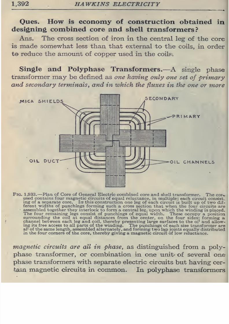
8/20/2019 electrical guide 5.pdf
http://slidepdf.com/reader/full/electrical-guide-5pdf 138/343
1,392
HAWKINS
ELECTRICITY
Oues.
How
is
economy
of
construction
obtained
in
designing
combined core and
shell
transformers?
Ans.
The
cross section
of iron in the
central
leg
of the
core
is
made
somewhat less
than that external
to
the
coils,
in
order
t©
reduce the amount of
copper
used
in the coils.
Single
and
Polyphase
Transformers.
—A single
phase
transformer may
be
defined as one having
only
one set
of
primary
and secondary terminalSy
and
in
which
the
fluxes
in
the
one or
more
JVllCA
6HIELDS
SECONDARY
OIL
DUCT
-PRIMARY
OIL
CHANNELS
Fig.
1,933.
—
Plan
of Core
of
General
Electric combined
core
and
shell
transformer.
The cor*,
used
contains four
magnetic
circuits
of
equal
reluctance,
in
multiple;
each
circuit
consist,
ing of a
separate
core.
In-
this
construction
one
leg of each
circuit
is
built
up
of
two
dif-
ferent
widths
of punchings
forming
such
a
cross
section
that
when the four
circuits
are
assembled together they
interlock
to
form
a central leg, upon
which the winding
is
placed.
The four remaining legs
consist
of
punchings of
equal width.
These occupy a
position
surrounding the
coil at
equal distances from
the center, on the four
sides; forming
a
channel
between each
leg
and coil,
thereby
presenting
large
surfaces to the
oi'
and allow-
ing its free access to all
parts
of
the
winding. The punchings of
each size transformer
are
all
of the same
length, assembled
alternately, and
forming
two lap joints
equally distributed
in
the four
comers of
the
core, thereby
giving a magnetic
circuit of low
reluctance.
magnetic
circuits
are
all
in
phase,
as distinguished
from
a
poly-
phase
transformer,
or combination
in
one unit'
of
several
one
phase
transformers with
separate electric
circuits
but having
cer-
tain magnetic circuits in
common.
In polyphase
transformers
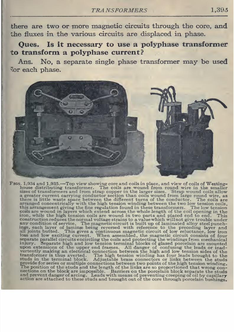
8/20/2019 electrical guide 5.pdf
http://slidepdf.com/reader/full/electrical-guide-5pdf 139/343
TRANSFORMERS
1,395
there are
two
or
more
magnetic
circmts
through
the
core,
and
'^he
fluxes
in the various
circuits are displaced in phase.
Oues.
Is
it necessary to use
a
polyphase transformer
to
transform
a
polyphase
current?
Ans.
No,
a
separate
single
phase
transformer
may
be
used
^r
each
phase.
Figs.
1
,934
and
1
,935.
—
Top
view showing core
and coils
in place,
and
view
of
coils
of Westing-
house distributing
transformer. The
coils
are
wound
from round wire
in
the smaller
sizes
of transformers and
from
strap
copper in the larger
sizes.
Strap
wound coils
allow
a
greater current
carrying conductor
section than coils wound from
large round
wire,
as
there
is
little waste
space
between the different turns
of
the conductor.
The
coils
are
arranged
concentrically
with
the
high
tension
winding
between
the
two
low
tension
coils,
this
arrangement
giving
the
fine
regulation found in these transformers. The
low
tension
coils
are
wound
in layers
which
extend
across
the
whole
length of the
coil
opening
in the
iron,
while
the high
tension coils
are
wound
in two parts and placed
end
to
end.
This
construction
reduces
the
normal voltage strains
to
a
value which will not give
trouble
under
any
condition
of
service.
The magnetic circuit is
built up
of laminated alloy
steel
punch-
ings,
each layer
of
laminae
being
reversed
with
reference
to
the preceding
layer
and
all
joints
butted.
This
gives
a
continuous
magnetic circuit
of
low reluctance,
low
iron
loss
and
low exciting
current. When assembled, the
magnetic
circuit
consists
of
four
separate
parallel
circuits
encircling the
coils
and
protecting
the windings
from
mechanical
injury.
Separate
high and low tension
terminal
blocks of glazed porcelain
are
mounted
upon
extensions
of the
upper
end
frames. All
danger
of
confusmg the
leads
or
inad-
vertently
making
an electrical connection
between
the
high
and
low
tension
sides
of
the
transformer
is thus averted
.
The
high
tension
winding
has
four
leads
brought
to
the
studs
in
the
terminal
block.
Adjustable
brass
connectors
or
links
between
the
studs
provide
for
series
or multiple
connections between
two
points
of
the
high
tension
winding.
The
position
of the
studs
and
the length of
the
links are so proportioned
that
wrong
con-
nections
on the
block
are
impossible. Barriers on
the
porcelain block
separate
the
studs
and
prevent
danger
of
arcing.
Leads
with
means of preventing
creeping
of
oil
by
capillary-
action
are
attached
to
these
studs and brought
out of the
core
through
porcelain
bushings.
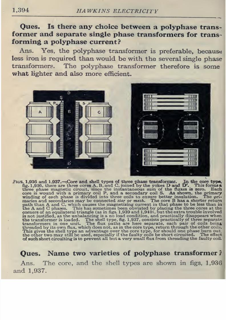
8/20/2019 electrical guide 5.pdf
http://slidepdf.com/reader/full/electrical-guide-5pdf 140/343
1,394
HAWKINS
ELECTRICITY
Ques. Is
there
any
choice
between
a
polyphase
trans-
former and
separate single
phase
transformers
for trans-
forming
a
polyphase
current?
Ans.
Yes,
the
polyphase
transformer
is
preferable,
becausti
less
iron
is
required
than
would
be with
the
several
single
phase
transformers.
The
polyphase
transformer
therefore is
some
what
lighter
and
also
more
efficient.
i'lGS.
1,936
and
1,937.—
Oore
and
shell types
of
three
phase transformer. In the
core
tyv^
fig.
1,936,
there
are
three cores
A,
B,
and
C,
joined by the
yokes
D
and
Jy.
This
forms
a
three
phase
magnetic
circuit, since
the
instantaneous
sum of the
flaxes is
zero.
Each
core
is wound
with a primary
coil P.
and
a
secondary coil S.
As
shown,
the
primary
winding
of each phase
is
divided
into three
coils
to ensure
better
insulation.
The
pri-
maries
and
secondaries
may be
connected star
or
mesh.
The
core B has a
shorter
return
path than A
and
C,
which
causes
the
magnetizing current in
that phase
to be
less
than
in
the A
and C
phases.
This
has
sometimes
been
obviated by placing the
three
cores
at
ths
comers of
an
equilateral
triangle
(as
in
figs.
1,939
and
1,940),
but the
extra
trouble
involved
is not
justified,
as
the
unbalancing
is
a
no
load
condition,
and
practically
disappears
when
the
transformer
is
loaded. The
shell type, fig.
1,937,
consists
practically of three
separate
transformers in
one
unit.
The
flux paths
are
here
separate,
each
pair of coils
beinft
threaded
by
its
own
flux,
which
does not, as in the core type,
return
through
the
other
coily.
This gives
the
shell
type an
advantage
over
the
core
type,
for
should
one
phase
burn
out,
the
other
two may
still
be
used,
especially
if the faulty
coils
be
short
circuited.
The effect
of
such ^ort
circuiting
is
to
prevent
all
but
a very
small flux
from
threading
the faulty coiL
Ques. Name
two
varieties
of
polyphase
transformer?
Ans.
The
core,
and the shell
types
are
shown
in figs,
1,936
and
1,937.
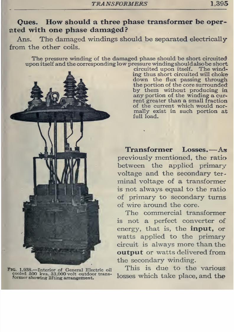
8/20/2019 electrical guide 5.pdf
http://slidepdf.com/reader/full/electrical-guide-5pdf 141/343
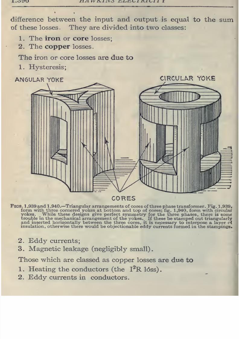
8/20/2019 electrical guide 5.pdf
http://slidepdf.com/reader/full/electrical-guide-5pdf 142/343
n ±
yyivii\C) r.i^iiL-i
i iui
i
i
difference
between
the
input
and
output
is
equal
to the
sum
of
these
losses.
They
are divided into
two
classes:
1. The
iron
or
core
losses;
2.
The copper
losses.
The
iron or
core
losses are
due to
1.
Hysteresis;
ANGULAR
YOKE
CIRCULAR YOKE
CORES
Figs.
1
,939
and
1
,940.—
Triangular
arrangements
of
cores
of
three
phase
transformer.
Fig.
1
,939,
form
with
three
cornered^
yokes
at bottom and
top of cores; fig.
1,940,
form with circulal
yokes. While
these
designs give
perfect symmetry
for the
three
phases,
there is some
trouble in
the mechanical
arrangement
of
the
yokes.
_
If
these
be stamped
out
triangularly
and inserted horizontally
between
the
three
cores, it
is necessary
to
interpose a layer o(
insulation,
otherwise
there would
be
objectionable eddy
currents formed in
the stampings.
2.
Eddy currents;
3. Magnetic leakage
(negligibly
small).
Those
which
are
classed as
copper
losses
are
due
to
1 Heating
the conductors
(the
I^R loss)
2.
Eddy currents
in
conductors.
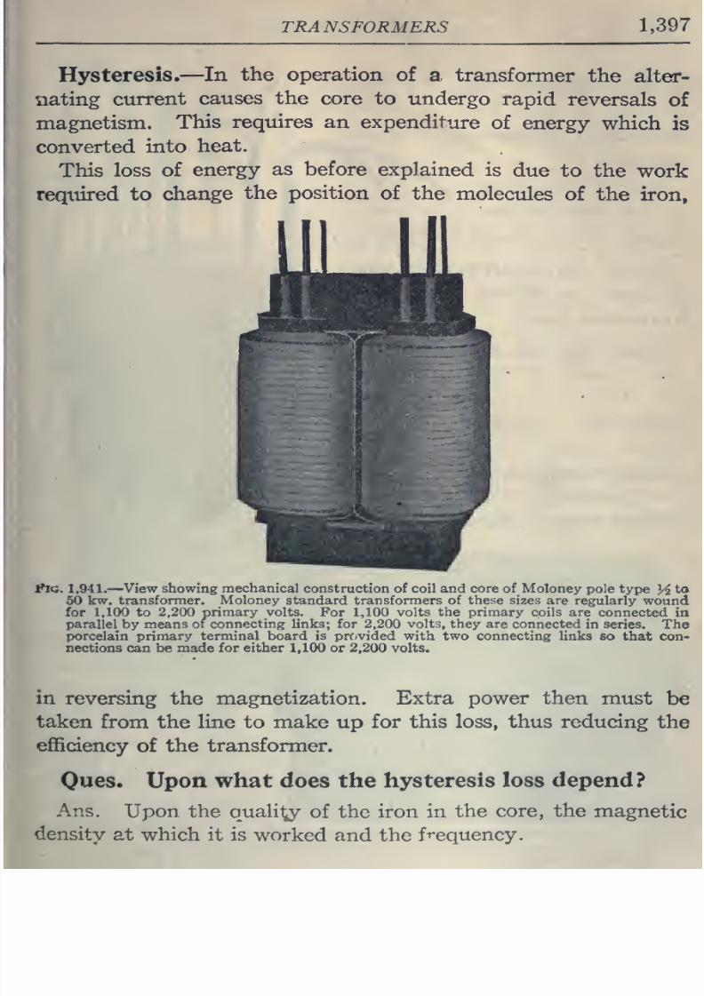
8/20/2019 electrical guide 5.pdf
http://slidepdf.com/reader/full/electrical-guide-5pdf 143/343
TRANSFORMERS
1,397
Hysteresis.
—In
the
operation
of
a,
transformer
the alter-
nating
current
causes
the
core
to
undergo
rapid
reversals
of
magnetism.
This
requires
an
expenditure
of
energy
which
is
converted
into
heat.
This
loss
of
energy
as
before
explained
is
due
to
the
work
required
to
change
the position
of
the
molectdes
of
the iron.
flQ.
1.941.
—
View
showing mechanical
construction
of coil and
core
of Moloney
pole
type
}4
to
50
kw.
transformer.
Moloney
standard
transformers of
these
sizes
are regularly
wound
for
1,100
to 2,200
primary volts.
For
1,100
volts
the
primary coils are
connected
in
parallel
by
means
of connecting links; for
2,200
volts,
they
are
connected
in
series. The
porcelain primary
terminal
board is provided
with
two
connecting
links so
that
con-
nections can be made
for either
1,100
or
2,200
volts.
in
reversing
the
magnetization.
Extra
power
then
must
be
taken
from the
line
to make
up
for
this loss, thus
reducing
the
efficiency
of
the
transformer.
Ques. Upon
what
does the
hysteresis
loss depend?
Ans.
Upon the
qualil^
of the
iron in
the
core,
the
magnetic
density
at
which it
is
worked
and the
frequency.
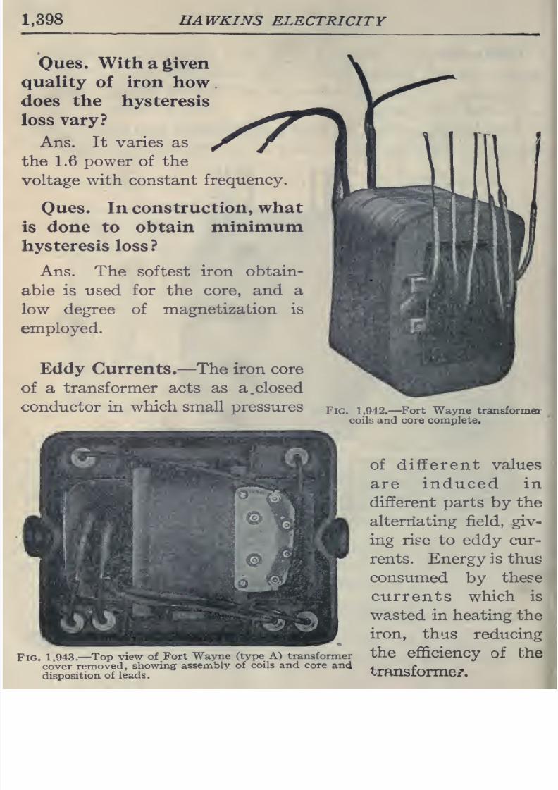
8/20/2019 electrical guide 5.pdf
http://slidepdf.com/reader/full/electrical-guide-5pdf 144/343
1,398
HAWKINS
ELECTRICITY
Ones.
With
a
given
quality
of
iron
how
does
the
hysteresis
loss
vary?
Ans.
It
varies as
the
1.6 power
of
the
voltage
with
constant
frequency.
Oues.
In
construction,
what
is
done
to
obtain
minimum
hysteresis loss ?
Ans. The
softest iron
obtain-
able is
used
for
the core, and a
low
degree
of
magnetization
is
employed.
Eddy
Currents.
—
The
iron core
of
a
transformer
acts as a.closed
conductor
in
which
small pressures
Fig.
1,943.—
Top
view of
Fort
Wayne
(type
A) transformer
cover
removed,
showing
assembly
of
coils and
core
and
disposition
of
leads.
Fig. 1,942.—
Fort
Wayne
transforme
coils
and
core
complete.
of different values
are
induced
in
different
parts
by
the
alternating field, giv-
ing
rise to eddy cur-
rents. Energy
is thus
consumed
by
these
currents
which is
wasted in
heating
the
iron, thus
reducing
the
efficiency
of
the
transforme/.
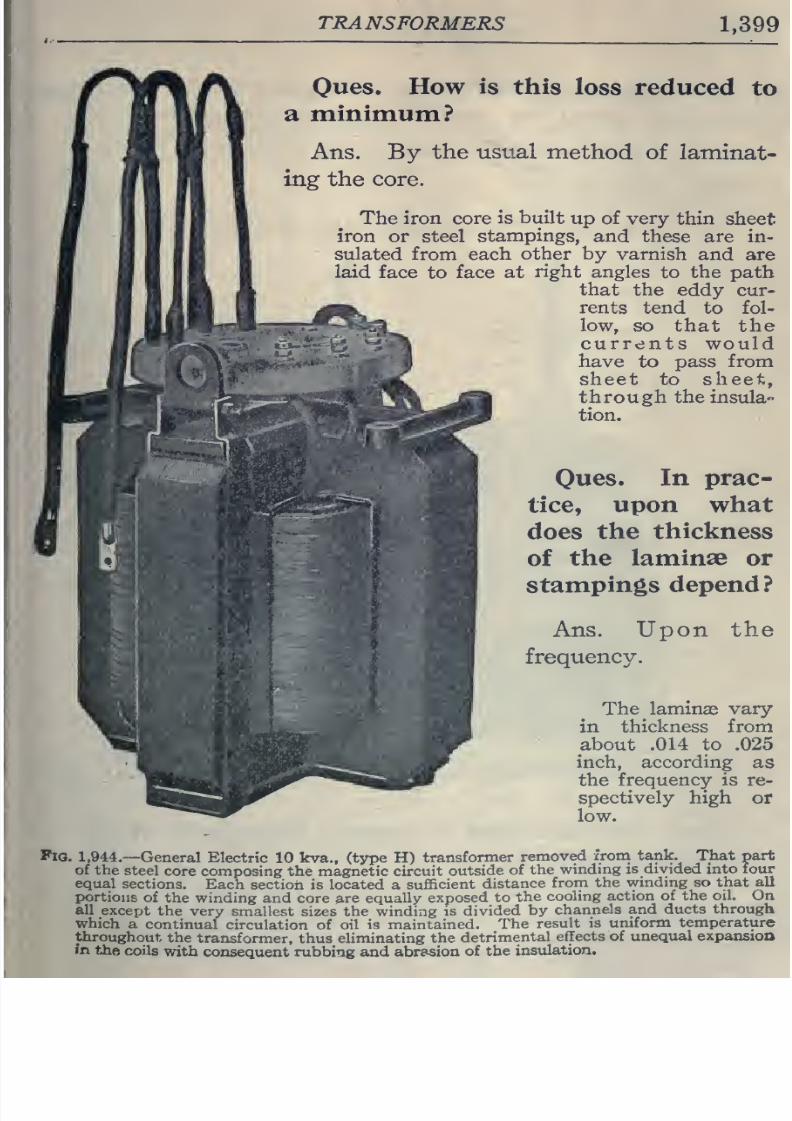
8/20/2019 electrical guide 5.pdf
http://slidepdf.com/reader/full/electrical-guide-5pdf 145/343
TRANSFORMERS
1,399
Oues.
How is
this
loss reduced
to
a
minimum?
Ans.
By
the
usual
method
of
laminat-
ing
the
core.
The
iron
core
is built
up
of
very
thin
sheet
iron or steel
stampings,
and
these are in-
sulated
from
each
other
by
varnish
and
are
laid
face
to face
at
right
angles
to
the
path
that the
eddy
cur-
rents tend
to
fol-
low,
so
that
the
currents
would
have
to
pass from
sheet to sheet,
through
the
insula-
tion.
Oues.
In prac-
tice,
upon
what
does
the
thickness
of
the
laminae
or
stampings
depend?
Ans. Upon
the
frequency.
The
laminae
vary
in
thickness from
about
.014
to
.025
inch,
according
as
the
frequency is
re-
spectively
high
or
low.
Fio.
1,944.—
General
Electric
10
kva.,
(type
H)
transformer
removed
xrom
tank.
That
part
of the
steel
core composing
the
magnetic
circuit
outside
of
the
winding
is divided into
four
equal
sections.
Each section
is
located
a
sufficient
distance
from
the
winding so
that
all
portions
of the winding
and
core
are
equally
exposed
to
the
cooling
action of
the oil.
On
all
except
the
very
smallest
sizes the winding
is
divided
by
channels
and
ducts through
which
a
continual
circulation
of oil
is
maintained.
The
result
is
uniform
temperature
throughout
the
transformer, thus
eliminating
the
detrimental
effects of
unequal
expansion
in
the
coils
with
consequent rubbing and abrasion
of the
insulation.
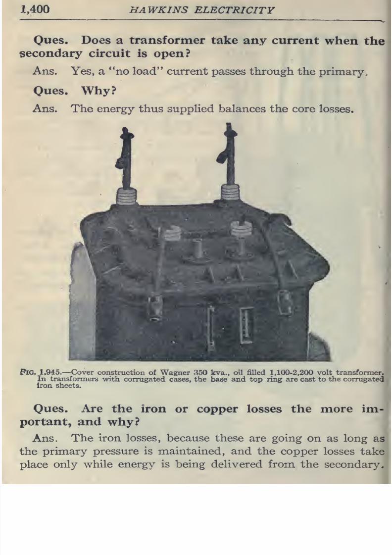
8/20/2019 electrical guide 5.pdf
http://slidepdf.com/reader/full/electrical-guide-5pdf 146/343
1,400
HAWKINS
ELECTRICITY
Ques,
Does
a
transformer
take
any
current
when
the
secondary
circuit
is
open?
Ans.
Yes,
a no load
current passes through
the
primary.
Ques.
Why?
Ans.
The
energy
thus
supplied balances
the
core
losses.
Pig.
1,945.—
Cover
construction
of Wagner
350 kva.,
oil
filled
1,100-2,200 volt
transformer.
In
transformers
with
corrugated cases,
the
base
and top ring are cast
to
the
corrugated
Iron
sheets.
Ques.
Are
the iron
or copper losses the
more
im-
portant,
and
why?
Ans.
The
iron losses,
because these
are
going
on
as
long
as
the
primary
pressure
is
maintained,
and the
copper losses
take
place
only
while energy is being
delivered from the
secondary.
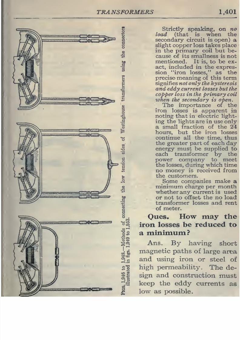
8/20/2019 electrical guide 5.pdf
http://slidepdf.com/reader/full/electrical-guide-5pdf 147/343
TRANSFORMERS
1,401
Strictly
speaking, on
no
load
(that is
when
the
secondary circuit is open)
a
slight copper loss
takes
place
in
the
primary
coil
but
be-
cause
of
its
smallness
is
not
mentioned. It is,
to
be
ex-
act, included in
the
expres-
sion
iron
losses,
as
the
precise
meaning
of this
term
signifies not
only
the
hysteresis
and
eddy
current losses
but
the
copper
loss in the
primary
coil
when the secondary
is
open.
The
importance of
the
iron
losses is
apparent
in
noting
that
in electric
light-
ing the
lights
are
in use
only
a
small
fraction
of the
24
hours,
but the iron
losses
continue
all
the
time,
thus
the
greater part of
each
day
energy
must
be
supplied
to
each
transformer
by
the
power company
to meet
the
losses,
during which
time
no
money
is
received from
the customers.
Some companies
make
a
minimum
charge per month
whether
any
current
is
used
or
not to
offset
the no load
transformer
losses
and
rent
of
meter.
Ones.
How
may
the
iron losses
be
reduced
to
a
minimutn?
Ans.
By having
short
magnetic
paths
of
large
area
and
using
iron
or
steel
of
high permeability.
The
de-
sign
and
construction
must
keep
the eddy
currents
as
low
as
possible.
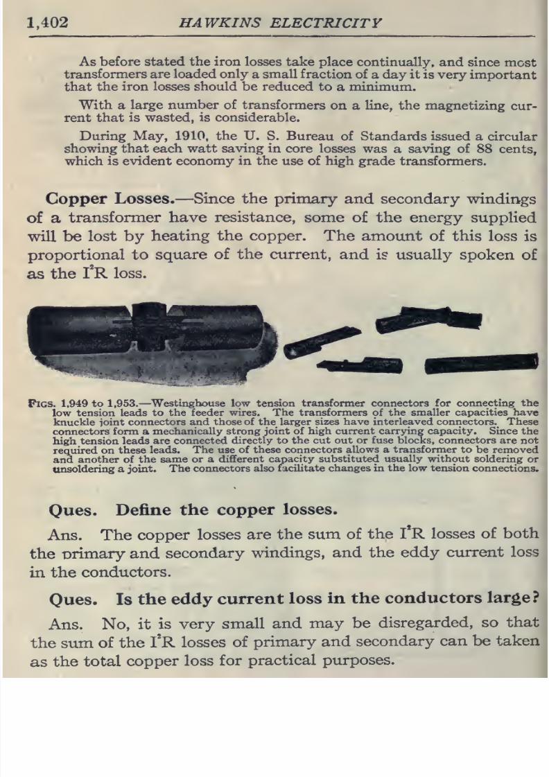
8/20/2019 electrical guide 5.pdf
http://slidepdf.com/reader/full/electrical-guide-5pdf 148/343
1,402
HAWKINS
ELECTRICITY
As
before
stated
the
iron
losses
take place
continually,
and
since
most
transformers
are loaded
only
a
small
fraction
of
a
day it
is very
important
that
the
iron
losses
should
be
reduced
to
a
minimum.
With
a
large
number of
transformers
on
a
line, the
magnetizing
cur-
rent
that
is
wasted,
is
considerable.
During
May, 1910,
the U.
S.
Bureau
of
Standards issued
a circular
showing
that each watt
saving in
core
losses
was
a
saving
of
88
cents,
which
is
evident economy
in
the
use of high
grade transformers.
Copper
Losses.
—
Since the
primary
and secondary
windings
of a
transformer have
resistance,
some of the energy
supplied
will
be
lost
by
heating
the
copper.
The
amount
of
this
loss
is
proportional to
square
of
the
current,
and
is usually
spoken
of
as
the
I^R
loss.
Figs. 1,949
to
1,953.
—
Westinghouse low
tension
transformer connectors for connecting the
low
tension
leads
to
the feeder
wires. The
transformers
of
the
smaller
capacities
have
knuckle ioint
connectors
and
those of the
larger sizes have interleaved connectors. These
connectors
form
a
mechanically
strong joint of
high current
carrying
capacity.
Since
the
high
tension
leads
are connected
directly
to
the
cut
out
or
fuse blocks,
connectors are
not
required
on
these
leads.
The use of
these
connectors
allows
a
transformer
to be
removed
and
another of
the
same
or
a
different capacity
substituted
usually without
soldering
or
unsoldering a
joint.
The
connectors
also
facilitate
changes in
the
low
tension
connections.
Ques.
Define the
copper
losses.
Ans.
The
copper
losses
are
the
sum
of
the
I
R
losses
of
both
the
Drimary
and
secondary
windings,
and
the eddy
current
loss
in
the
conductors.
Ques.
Is
the
eddy
current
loss
in the
conductors
large?
Ans.
No,
it
is very
small
and
may
be
disregarded, so
that
the sum
of
the
I*R
losses
of
primary
and
secondary
can
be
taken
as
the
total
copper
loss
for
practical
purposes.
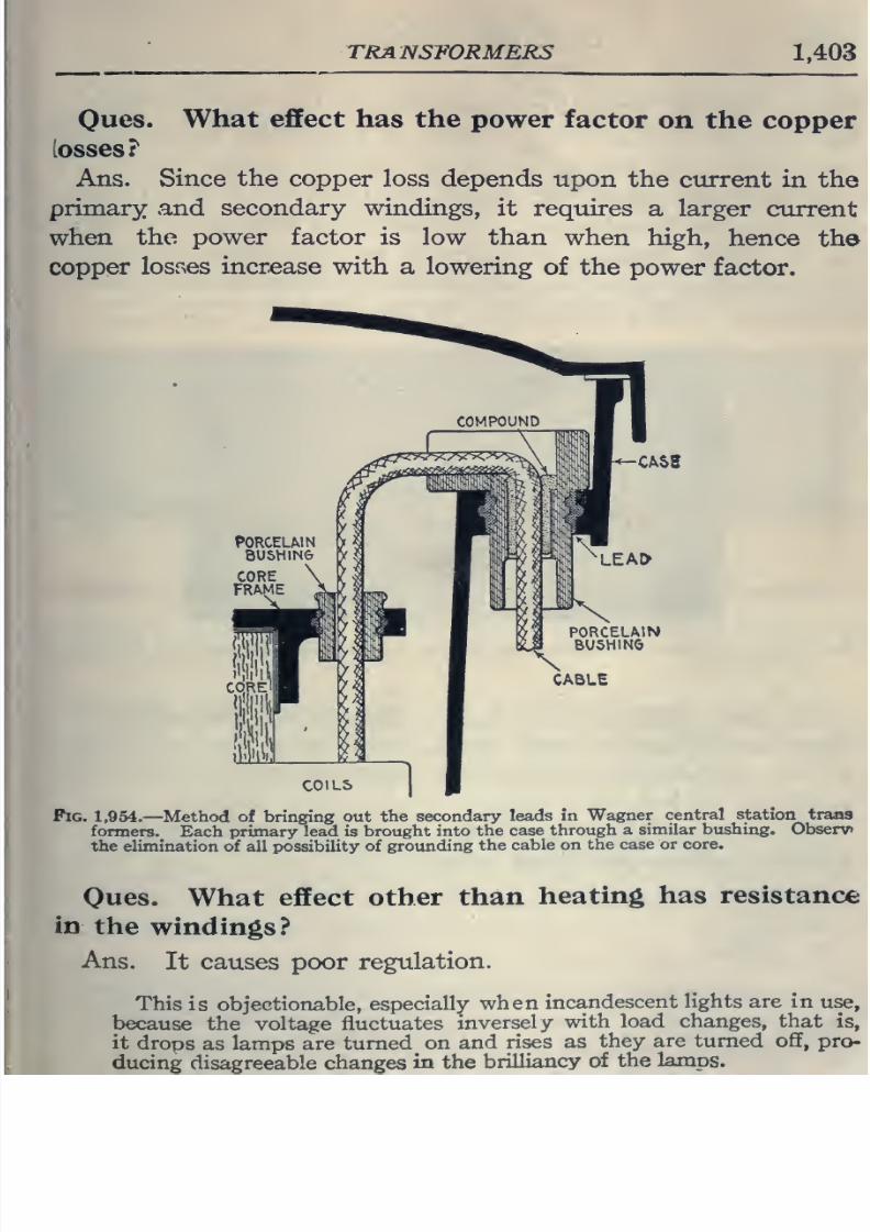
8/20/2019 electrical guide 5.pdf
http://slidepdf.com/reader/full/electrical-guide-5pdf 149/343
TRANSFORMERS
1,403
Oues.
What
effect
has
the
power
factor
on
the
copper
losses?
Ans. Since
the
copper
loss
depends
upon
the
current
in
the
primary and
secondary
windings,
it
requires
a
larger
current
when
the
power
factor
is
low
than
when high,
hence
the
copper
losvses
increase
with
a lowering
of the
power factor.
CASE
C0IL5
Pig. 1,954.
—
Method
of
bringing
out
the
secondary
leads in
Wagner
central station
trans
formers.
Each
primary
lead
is
brought into
the
case
through
a
similar
bushing.
Observ»
the elimination of
all possibility of
grounding
the
cable
on the
case
or
core.
Oues.
What effect
other
than
heating
has resistance
in
the
windings?
Ans.
It causes poor
regulation.
This
is objectionable,
especially
when
incandescent
lights are
in
use,
because
the
voltage
fluctuates
inversely
with
load
changes, that is,
it
drops
as lamps
are
turned
on
and
rises as
they
are
turned ofif,
pro-
ducing
disagreeable changes
in
the
brilliancy
of
the
lamps.
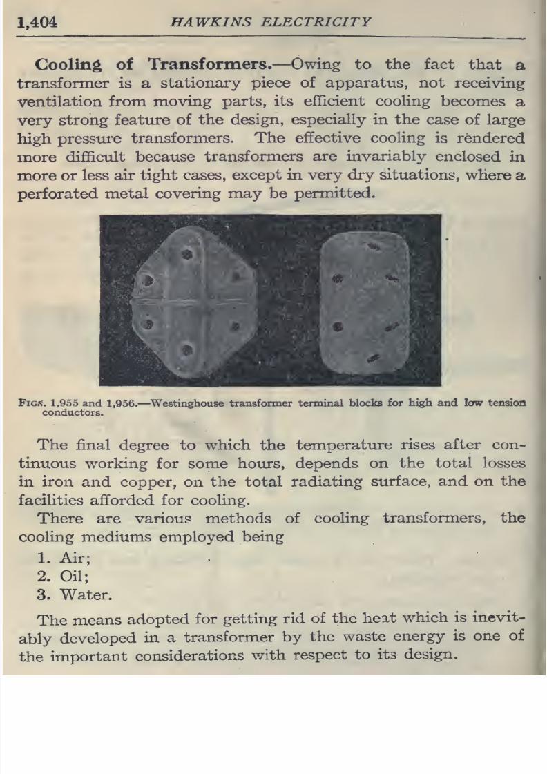
8/20/2019 electrical guide 5.pdf
http://slidepdf.com/reader/full/electrical-guide-5pdf 150/343
1,404
HAWKINS ELECTRICITY
Cooling
of
Transformers.—
Owing to
the
fact
that
a
transformer
is
a
stationary
piece
of
apparatus, not
receiving
ventilation
from
moving
parts, its
efficient
cooHng
becomes
a
very
strong
feature
of
the
design, especially in
the
case
of large
high
pressure
transformers.
The effective
cooling
is
rendered
more
difficult
because
transformers
are
invariably
enclosed
in
more or
less
air
tight
cases,
except in
very
dry
situations,
where a
perforated
metal
covering
may
be
permitted.
Figs.
1,955
and
1,956.
—
^Westinghouse
transformer terminal
blocks
for high and law
tension
conductors.
The final
degree
to
which
the
temperature
rises
after con-
tinuous working
for some hours,
depends on
the
total
losses
in
iron
and copper,
on
the
total
radiating
surface,
and
on the
facilities
afforded for
cooling.
There
are
various methods
of
cooling
transformers, the
cooling
mediums
employed
being
1.
Air;
2.
Oil;
3. Water.
The
means
adopted
for
getting
rid
of
the
heat
which
is
inevit-
ably
developed
in a
transformer by
the
waste
energy
is
one
of
the
important
considerations
v/ith
respect
to
its
design.
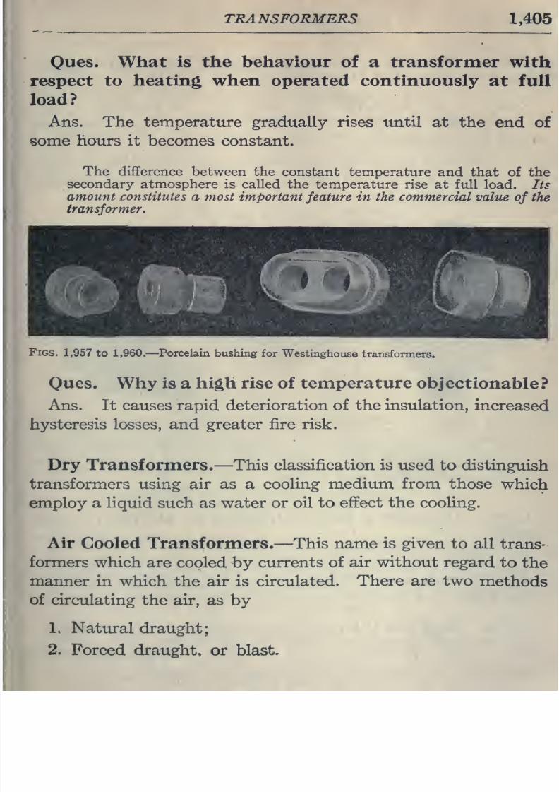
8/20/2019 electrical guide 5.pdf
http://slidepdf.com/reader/full/electrical-guide-5pdf 151/343
TRANSFORMERS
1,405
Oues.
What
is
the
behaviour
of
a
transformer
with
respect
to
heating
when operated continuously
at full
load?
Ans.
The
temperature
gradually
rises
until
at
the
end
of
some
hours it
becomes
constant.
The difference
between the
constant temperature
and
that of the
secondary atmosphere is called the
temperature
rise
at full
load. Its
amount
constitutes
a
most
important
feature
in
the commercial
value
of
the
transformer.
Figs,
1,957 to
1,960.
—
Porcelain bushing
for
Westinghouse
transformers.
Owes.
Why
is
a
high
rise
of
temperature
objectionable?
Ans. It
causes
rapid
deterioration
of the
insulation,
increased
hysteresis losses,
and greater
fire
risk.
Dry Transformers.
—
This classification is
used to distinguish
transformers
using
air
as
a
cooling
medium
from
those
which
employ
a liquid
such as water
or oil to
effect the cooling.
Air
Cooled Transformers.
—
This name
is
given to
all
trans-
formers
which are cooled
by
currents
of
air without
regard
to
the
manner
in
which
the
air is circulated.
There
are
two
methods
of
circulating
the
air,
as
by
1.
Natural draught;
,
2.
Forced
draught,
or
blast.
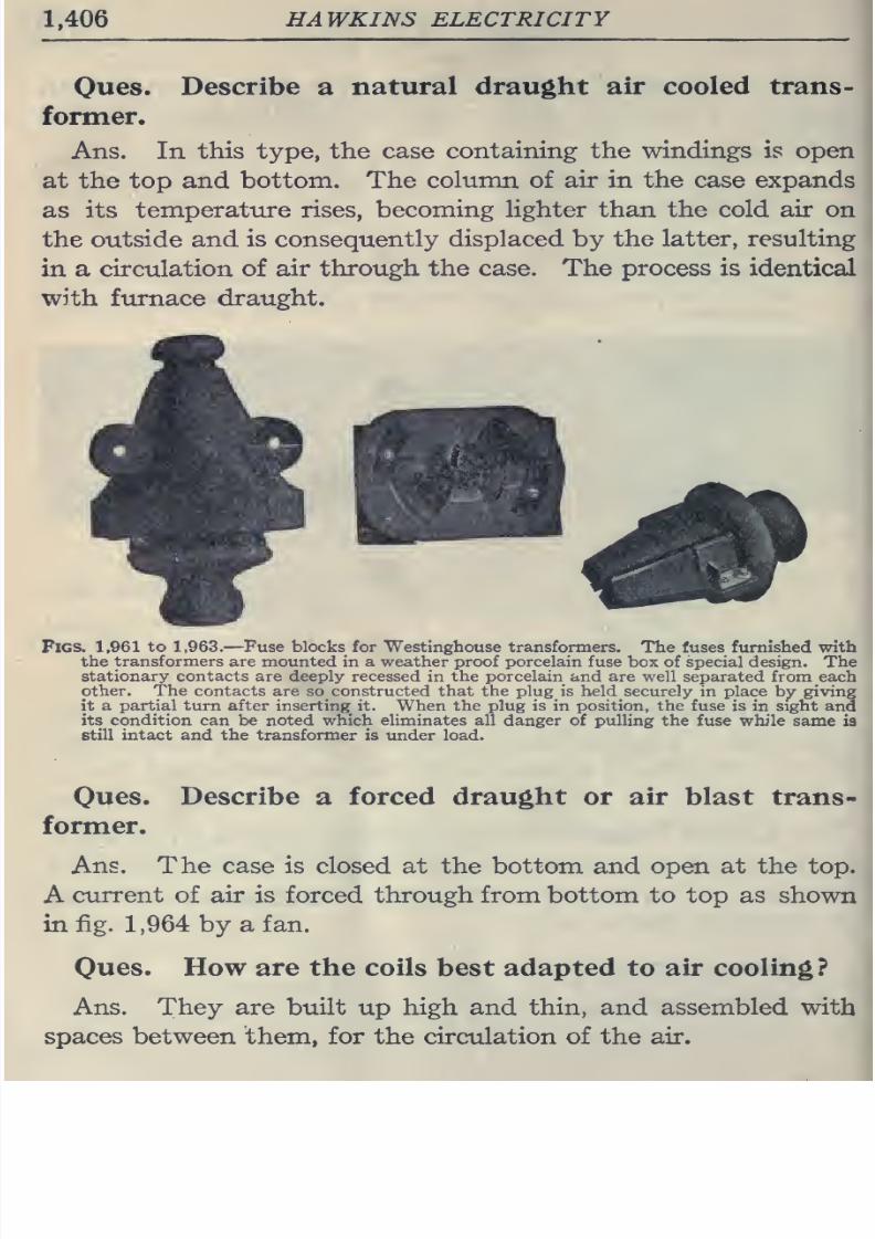
8/20/2019 electrical guide 5.pdf
http://slidepdf.com/reader/full/electrical-guide-5pdf 152/343
1,406
HAWKINS
ELECTRICITY
Ones.
Describe
a
natural draught
air cooled trans-
former.
Ans.
In
this
type,
the case
containing the
windings is
open
at
the
top
and
bottom.
The
column
of
air
in
the
case
expands
as
its
temperature
rises, becoming Hghter
than
the
cold
air
on
the
outside and
is consequently
displaced
by
the
latter,
resulting
in a
circulation of
air through
the
case.
The process is
identical
with
furnace
draught.
Figs. 1,961
to
1,963.
—
Fuse blocks
for
Westinghouse
transformers.
The
fuses
furnished
with
the
transformers
are
mounted
in
a weather
proof porcelain
fuse
box of
special design.
The
stationary contacts are
deeply recessed in the porcelain and are well
separated
from
each
other.
The
contacts
are
so
constructed
that the
plug
is
held
securely in place
by
giving
it
a
partial
turn
after inserting it. When the plug is in
position,
the
fuse is in sight
and
its
condition
can
be
noted
which eliminates all
danger
of pulling
the
fuse while same
is
still intact and the transformer
is
under
load.
Oues.
Describe
a
forced draught or air blast
trans-
former.
Ans. The case is
closed at the bottom
and
open at the
top.
A
current
of
air
is forced
through from bottom to
top
as
shown
in fig.
1,964
by a
fan.
Oues.
How are
the
coils best adapted to air cooling?
Ans.
They
are
built
up
high
and
thin,
and assembled
with
spaces
between
them,
for
the circulation of the air.
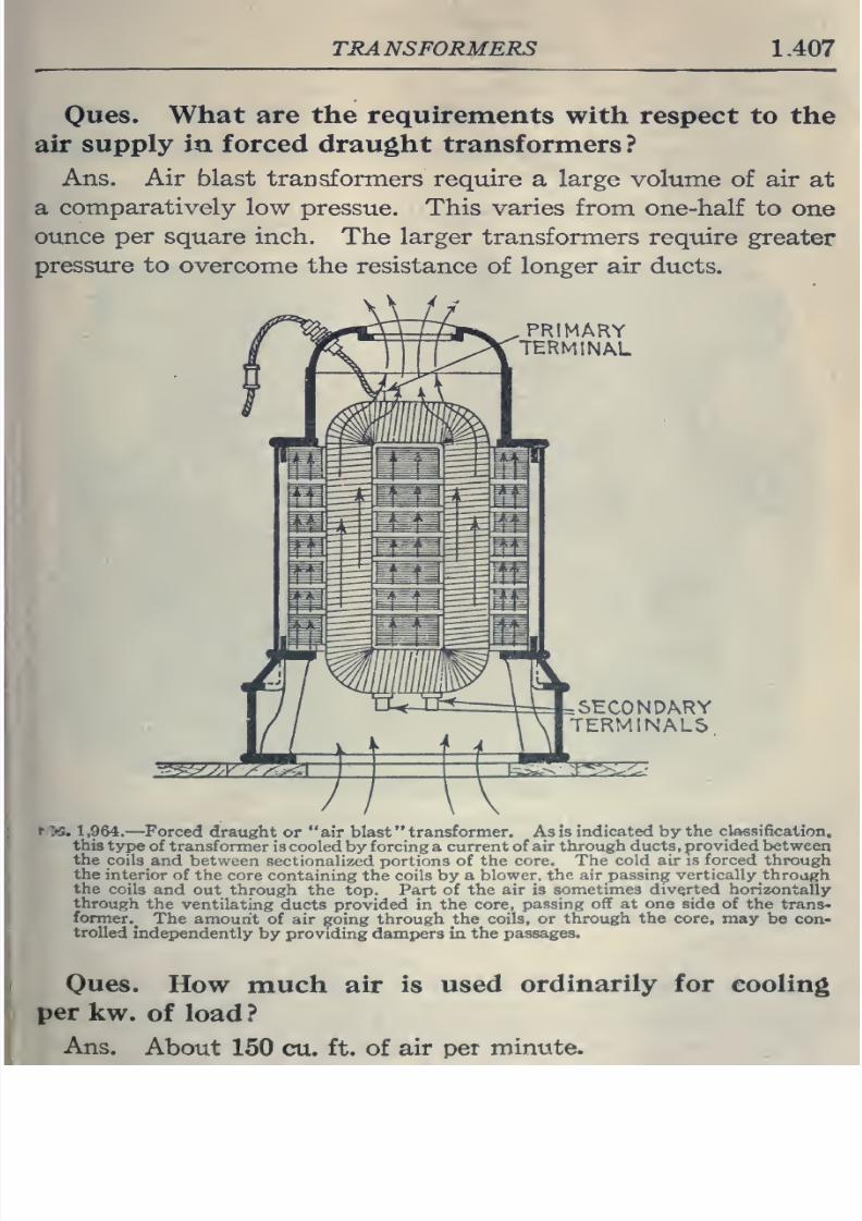
8/20/2019 electrical guide 5.pdf
http://slidepdf.com/reader/full/electrical-guide-5pdf 153/343
TRANSFORMERS
1.407
Ques.
What are
the
requirements
with
respect
to the
air supply
in
forced
draught
transformers
?
Ans.
Air
blast
transformers
require
a
large
volume
of
air
at
a
comparatively
low
pressue.
This varies
from one-half
to
one
oimce
per
square inch.
The larger transformers
require
greater
pressure to
overcome
the resistance
of longer
air
ducts.
PRIMARY
TERMINAL
SHCONDARY
TERMINALS
'•S.
1
,964.
—Forced
draught
or
air blast
transformer.
As
is
indicated
by
the
classification,
this
type
of
transformer
is
cooled
by
forcing
a
current
of air
through ducts,
provided
between
the
coils
and
between
sectionalized
portions
of the
core.
The cold
air is
forced
through
the
interior
of
the
core
containing the coils by a
blower,
the
air passing vertically through
the
coils
and out
through the top.
Part of the
air is
sometimes
diverted
horizontally
through
the
ventilating
ducts
provided
in
the
core,
passing
off at one
side
of
the
trans-
former.^
The amount
of air going through the
coils, or
through
the core, may
be
con-
trolled
independently
by
providing
dampers
in
the
passages.
Ques.
How
much air is
used
ordinarily
for cooling
per
kw.
of
load ?
Ans.
About
150
cu.
ft. of
air
per
minute.
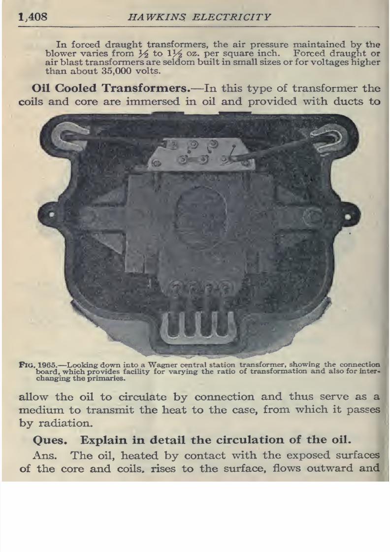
8/20/2019 electrical guide 5.pdf
http://slidepdf.com/reader/full/electrical-guide-5pdf 154/343
1,408
HAWKINS
ELECTRICITY
In
forced draught
transformers,
the
air
pressure
maintained
by
the
blower
varies
from
^
to
13^
oz.
per square
inch.
Forced draught or
air
blast
transformers
are seldom built
in small
sizes or for
voltages
higher
than
about
35,000
volts.
Oil Cooled
Transformers.
—
In
this type
of
transformer
the
coils
and core are immersed in
oil
and
provided with
ducts to
FlO,
1965.
—
Looking down
into
a
Wagner
central station
transformer,
showing
the
connection
board,
which
provides
facility
for
varying the
ratio
of
transformation and also for inter,
changing the
primaries.
allow
the
oil
to
circulate
by
connection
and thus
serve
as
a
medium
to
transmit
the
heat
to the
case,
from
which
it passes
by
radiation.
Ones.
Explain in
detail the
circulation
of
the
oil.
x\ns.
The oil, heated by
contact
with
the exposed
surfaces
of
the core and
coils,
rises
to
the
surface,
flows
outward
and
i
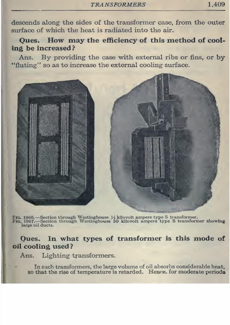
8/20/2019 electrical guide 5.pdf
http://slidepdf.com/reader/full/electrical-guide-5pdf 155/343
TRANSFORMERS 1.409
descends
along
the sides
of the
transformer
case,
from
the
outer
surface
of
which
the
heat
is
radiated into
the
air.
Ones.
How
may
the efficiency of
this
method
of
cool-
ing
be
increased?
Ans.
By providing the
case with
external
ribs or fins,
or
by
**fluting
so
as to increase
the
external
cooling siirface.
Fig.
1966.
—Section
through
Westinghouse
H
kilovolt
ampere
type S
transformer.
Fig.
1967.
—
Section
through Westinghouse
60
kilovolt
ampere type S
transformer
showing
large oil
ducts.
Oues.
In
what
types
of
transformer
is this
mode
of
oil
cooling
used
?
Ans. Lighting
transformers.
In such
transformers,
the
large
volume of
oil
absorbs considerable
heat,
so that the rise
of temperature
is retarded.
Hence,
for
moderate
periods
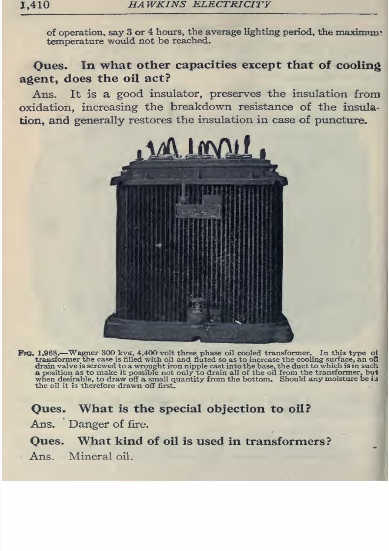
8/20/2019 electrical guide 5.pdf
http://slidepdf.com/reader/full/electrical-guide-5pdf 156/343
1,410
HAWKINS
ELECTRICITY
of
operation, say
3
or
4
hours,
the
average
lighting
period,
the
maximiin^
temperature
would
not
be
reached.
Ques.
In
what
other
capacities except
that
of
cooling
agent,
does
the
oil
act?
Ans.
It is a
good
insulator, preserves
the
insulation
from
oxidation,
increasing
the
breakdown resistance
of the
insula-
tion,
and
generally
restores
the insulation in case
of
puncture.
FW.
1,96S.
—
^Wagner
300
kva\
4,400 volt three phase
oil
cooled
transformer.
In
this
type
ot
transformer
the
case
is
filled
with
oil
and fluted
so
as
to increase
the cooling
surface,
an ofl
drain
valve is screwed
to a
wrought
iron nipple cast into the
base,
the duct
to
which is in
such
a
position
as to make
it
possible not only to
drain all
of
the
oil
from the
transformer, but
when
desirable, to draw
off
a
small
quantity
from the bottom.
Should
any
moisture be
i
j
the
oil
it
is
therefore drawn off
first.
Ques. What
is
the
special
objection
to
oil?
Ads.
Danger
of fire.
Ques.
What
kind
of
oil
is
used
in transformers?
Ans.
Mineral oil.
i
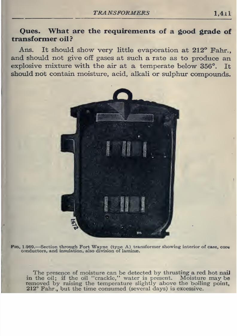
8/20/2019 electrical guide 5.pdf
http://slidepdf.com/reader/full/electrical-guide-5pdf 157/343
TRANSFORMERS
l,4li
Ques. What are
the
requirements
of
a
good
grade
of
transformer
oil?
Ans.
It
should
show
very
little
evaporation
at
212°
Fahr.,
and
should
not
give
off
gases
at such
a
rate
as
to
produce
an
explosive
mixture with
the air at
a temperate
below
356°.
It
should
not
contain
moisture,
acid, alkali
or
sulphur
compoimds.
Pio. 1-969.
—
Section
through
Fort
Wayne
(type A)
transformer showing
interior
of case,
cot*)
conductors, and insulation, also division of
laminae.
The presence of moisture
can
be
detected
by
thrusting
a red hot
nail
in
the oil;
if
the oil
crackle, water
is
present.
Moisture
maybe
removed
by
raising
the
temperature
slightly
above
the boiling
point,
212°
Fahr., but the time
consumed
(several days) is excessive.
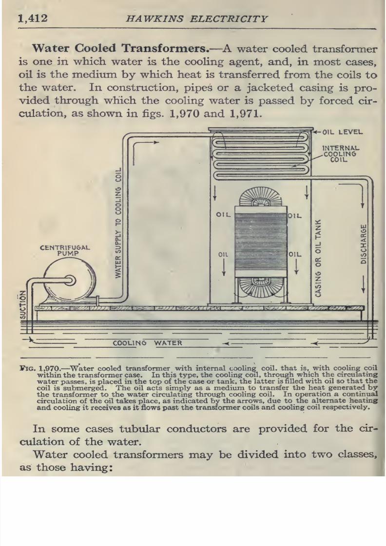
8/20/2019 electrical guide 5.pdf
http://slidepdf.com/reader/full/electrical-guide-5pdf 158/343
1,412
HAWKINS
ELECTRICITY
Water
Cooled
Transformers.
—
^A water
cooled
transformer
is
one
in which
water is
the
cooling
agent,
and, in most
cases,
oil
is
the
medium
by
which
heat is
transferred
from
the
coils
to
the
water. In construction,
pipes
or
a jacketed casing
is
pro-
vided
through
which
the
cooling
water is
passed
by
forced
cir-
culation, as
shown
in
figs.
1,970
and
1,971.
OIL
LEVEL
Fig.
1,970.
—
^Water
cooled
transfonner with internal
cooling
coil, that
is,
with
cooling
coil
within the
transformer
case. In
this
type, the
cooling coil,
through which
the circulating
water
passes, is
placed in
the top
of
the
case
or
tank, the
latter
is
filled
with oil so that
the
coil is
submerged. The oil
acts
simply as a
medium to
transfer
the
heat
generated
by
the
transformer
to
the water circulating
through cooling coil. In
operation
a
continual
circulation
of
the
oil
takes
place,
as indicated
by the
arrows,
due
to
the alternate
heating
and
cooling it receives as it flows
past the
transformer
coils
and
cooling
coil
respectively.
In
some
cases tubular
conductors are
provided
for
the
cir-
culation
of the water.
Water cooled
transformers
may be
divided
into
two
classes,
as
those
having:
^1
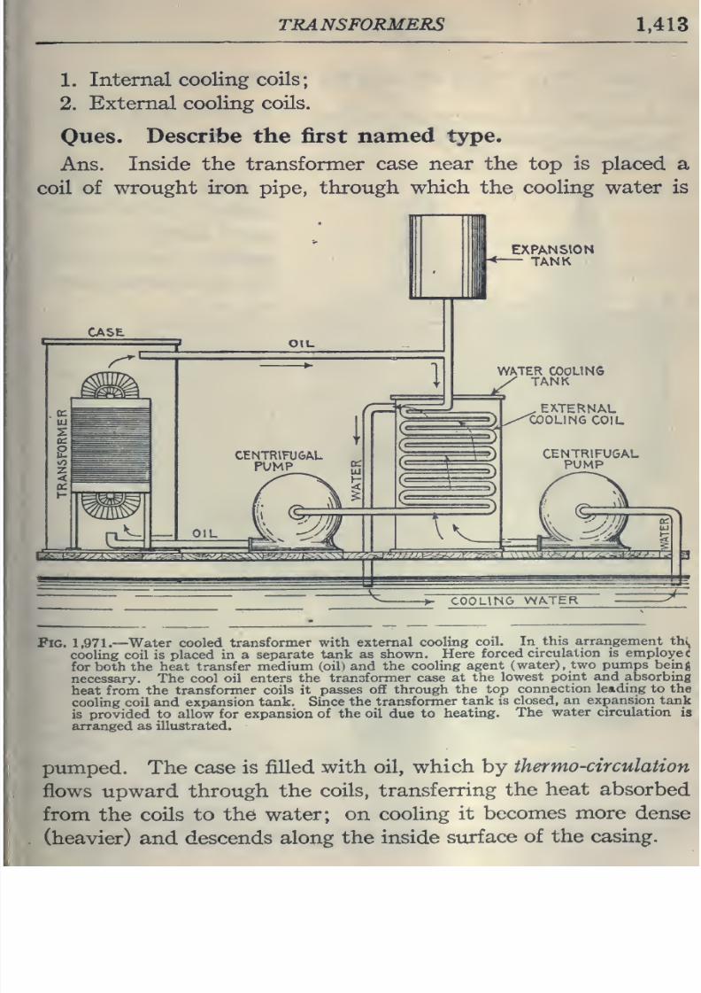
8/20/2019 electrical guide 5.pdf
http://slidepdf.com/reader/full/electrical-guide-5pdf 159/343
TRANSFORMERS
1,413
1.
Internal
cooling coils
2.
External
cooling
coils.
Oues.
Describe
the first
named
type.
Ans.
Inside
the
transformer
case near
the
top
is
placed
a
coil
of
wrought
iron
pipe,
through
which
the
cooling water is
I
EXPANSION
CASE
WATER
COOLING
y
TANK
^
EXTERNAL
^/'^OLING
COIL
Pig.
1,971.
—
Water cooled
transformer
with
external cooling
coil.
In
this arrangement \h\.
cooling
coil
is
placed
in
a
separate
tank
as
shown.
Here
forced
circulation is
employee
for
both the
heat transfer
medium
(oil) and the
cooling
agent
(water),
two
pumps being
necessary.
The
cool oil
enters
the
transformer
case
at
the
lowest
point
and
absorbing
heat
from
the
transformer coils
it
passes off
through
the
top
connection
leading
to the
cooling
coil and
expansion tank.
Since
the
transformer
tank
is
closed, an
expansion
tank
is
provided
to
allow
for
expansion
of
the
oil due
to
heating.
The
water
circulation
is
arranged
as
illustrated.
pumped. The
case is filled
with
oil, which by
thermo-circulation
flows
upward through
the
coils,
transferring
the
heat
absorbed
from the
coils
to
the
water;
on cooling
it
becomes
more
dense
(heavier)
and
descends
along the inside
surface
of the
casing.
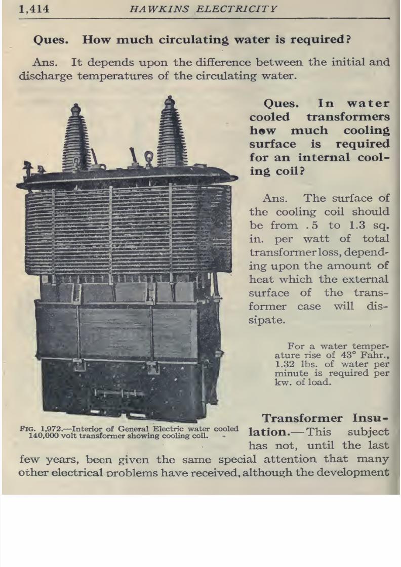
8/20/2019 electrical guide 5.pdf
http://slidepdf.com/reader/full/electrical-guide-5pdf 160/343
1,414
HAWKINS ELECTRICITY
Ones.
How
much
circulating water
is
required?
Ans. It depends upon
the
difference
between
the
initial
and
discharge
temperatures of
the
circulating
water.
Ones.
In water
cooled
transformers
hew
much
cooling
surface
is
required
for
an
internal
cool-
ing
coil?
x\ns.
The
surface
of
the
cooling
coil
should
be
from
.5
to
1.3
sq.
in.
per
watt
of
total
transformer
loss, depend-
ing
upon
the
amount
of
heat
which
the external
surface
of
the trans-
former
case
will
dis-
sipate.
For
a
water
temper-
ature
rise
of
43°
Fahr.,
1.32
lbs.
of
water
per
minute
is
required
per
kw.
of load.
Pig. 1,972.
—
Interior
of General
Electric
water
cooled
140,000 volt
transformer showing
cooling
coil.
Transformer
Insu-
lation.
—
This
subject
has
not,
until
the
last
few
years,
been
given
the same
special
attention
that
many-
other
electrical
oroblems
have
received,
although
the
development
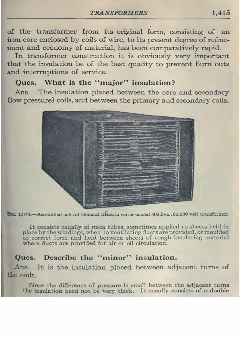
8/20/2019 electrical guide 5.pdf
http://slidepdf.com/reader/full/electrical-guide-5pdf 161/343
TRANSFORMERS
1,415
of
the
transformer
from
its
original
form, consisting
of
an
iron
core
enclosed
by
coils
of wire,
to its present
degree of
refine-
ment
and
economy of
material,
has
been comparatively
rapid.
In
transformer construction
it is
obviously very
important
that
the insulation
be
of the best
quality to
prevent
burn
outs
and
interruptions of
service.
Oues.
What
is the
**inajor
insulation?
Ans.
The
insulation
placed
between the
core
and
secondary
(low pressure)
coils,
and
between
the primary
and
secondary
coils.
Fig.
1,973.
—
^Assembled
coils of
General Electric
water
cooled
500
kva., 66,000
volt
transfonner.
It
consists
usually
of mica tubes,
sometimes
applied
as sheets
held
in
place
by
the
windings,
when
no
ventilating ducts
are
provided,
or moulded
to correct
form
and
held between sheets
of
tough
insulating
material
where
ducts are
provided
for
air
or
oil
circulation.
Oues.
Describe
the
**minor
insulation.
Ans.
It is
the
insulation placed
between
adjacent
turns
of
the
coils.
Since
the difference of
pressure
is
small
between
the
adjacent turns
the
insulation
need
not
be
very
thick.
It
usually
consists of
a
double
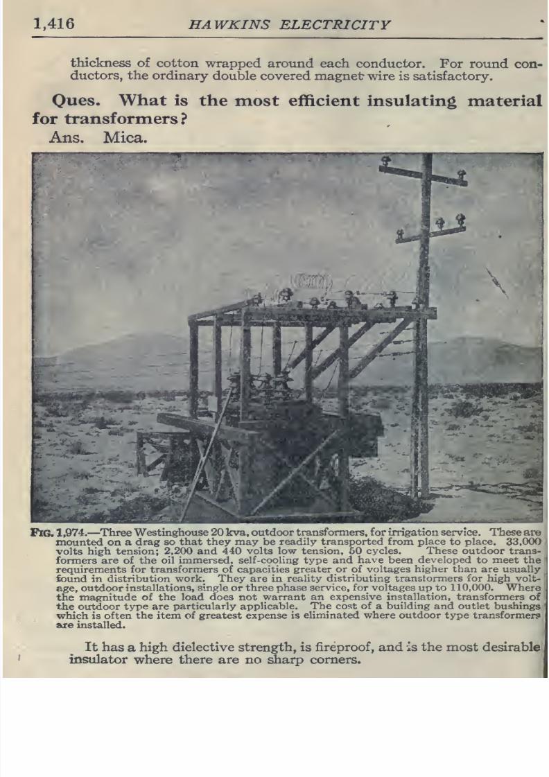
8/20/2019 electrical guide 5.pdf
http://slidepdf.com/reader/full/electrical-guide-5pdf 162/343
1,416
HAWKINS
ELECTRICITY
thickness
of
cotton
wrapped around
each conductor.
For round
con-
ductors, the
ordinary
double
covered
magnet wire is satisfactory.
Ones.
What
is
the
most
efficient insulating
material
for
transformers?
Ans.
Mica.
Pig.
1
,974.
—
Three
Westinghouse
20
kva,
outdoor
transformers, for
irrigation
service. I'hese
are
mounted
on a
drag so
that they may
be
readily
transported
from place
to
place.
33,000
volts
high
tension;
2,200 and
440 volts
low
tension,
50
cycles.
These
outdoor
trans-
formers
are
of the oil
immersed,
self-cooling
type
and
have
been
developed
to meet
the
requirements for
transformers
of
capacities
greater or
of
voltages
higher
than
are
usually
found
in
distribution
work.
They are
in
reality
distributing transtormers for
high volt-
age,
outdoor
installations,
single
or
three
phase
service, for
voltages
up
to
110,000.
Where
the
magnitude of
the
load does
not
warrant
an expensive
installation, transformers
of
the
oirtdoor
type are
particularly applicable.
The cost of
a
building and outlet
bushings
which
is
often
the
item
of
greatest
expense
is
eliminated
where outdoor
type
transformer?
are
installed.
It
has
a
high dielective
strength,
is
fireproof,
and is
the most
desirable
insulator
where
there
are no
^arp
corners.
8/20/2019 electrical guide 5.pdf
http://slidepdf.com/reader/full/electrical-guide-5pdf 163/343
ALTERNATORS
1,417
Oil
Insulated
Transformers.
—
High
voltage
transformers
are insiilated
with
oil, as
it
is
very
important
to
maintain
careful
insulation
not
only
between the
coils,
but
also
between the
coils
and
the
core.
In
the
case
of
high
voltage
transformers,
any
accidental
static
discharge, such as
that
due to
lighting,
which
might
destroy
one of
the air insulated
type,
might
be
success-
fully
withstood
by
one insulated
with
oil,
for
if
the
oil insulation
be
damaged it
will
mend
itself
at
once.
By providing
good
circulation for the oil,
the transformer
can
get rid
of the
heat produced
in
it
readily
and operate at
a
low
temperature,
which
.not only
increases its
life
but
cuts
down
the electric
resistance
of
the copper conductors
and
therefore
the
I'
R
loss.
Efficiency
of
Transformers.
—
The
efficiency of
transformers
is
the
ratio
of
the
electric
power
delivered
at
the
secondary
terminals
to
the
electric
power
absorbed
at
the
primary terminals.
Accordingly,
the output
must
equal
the input minus
the
losses. If
the
iron
and copper losses
at
a
given
load be known,
their
values
and
consequently
the efficiency
at
other
loads
may
be
readily
calculated.
EXAMPLE.
—
If
a
10
kilowatt
constant
pressure
transform.er
at
full
load
and
temperature
have
a
copper
loss of
.16
kilowatt,
or
1.6
per
cent.,
and the
iron loss
be
the
same,
then
its
efficiency
=
^^^^^^
—
X
100
=
96.9 per
cent
input
10
+
.
16
+
.
16
At three-quarters
load the
output will
be
7.5
kilowatts;
and
as
the
iron
loss
is
practically
constant
at
all
loads
and
the
copper
loss
is
proportional
to
the
square
of
the
load,
the
efficiency
=
=
'-
X
100
=
96.8 per
cent.
input 7.5
+
.
16
+
.09
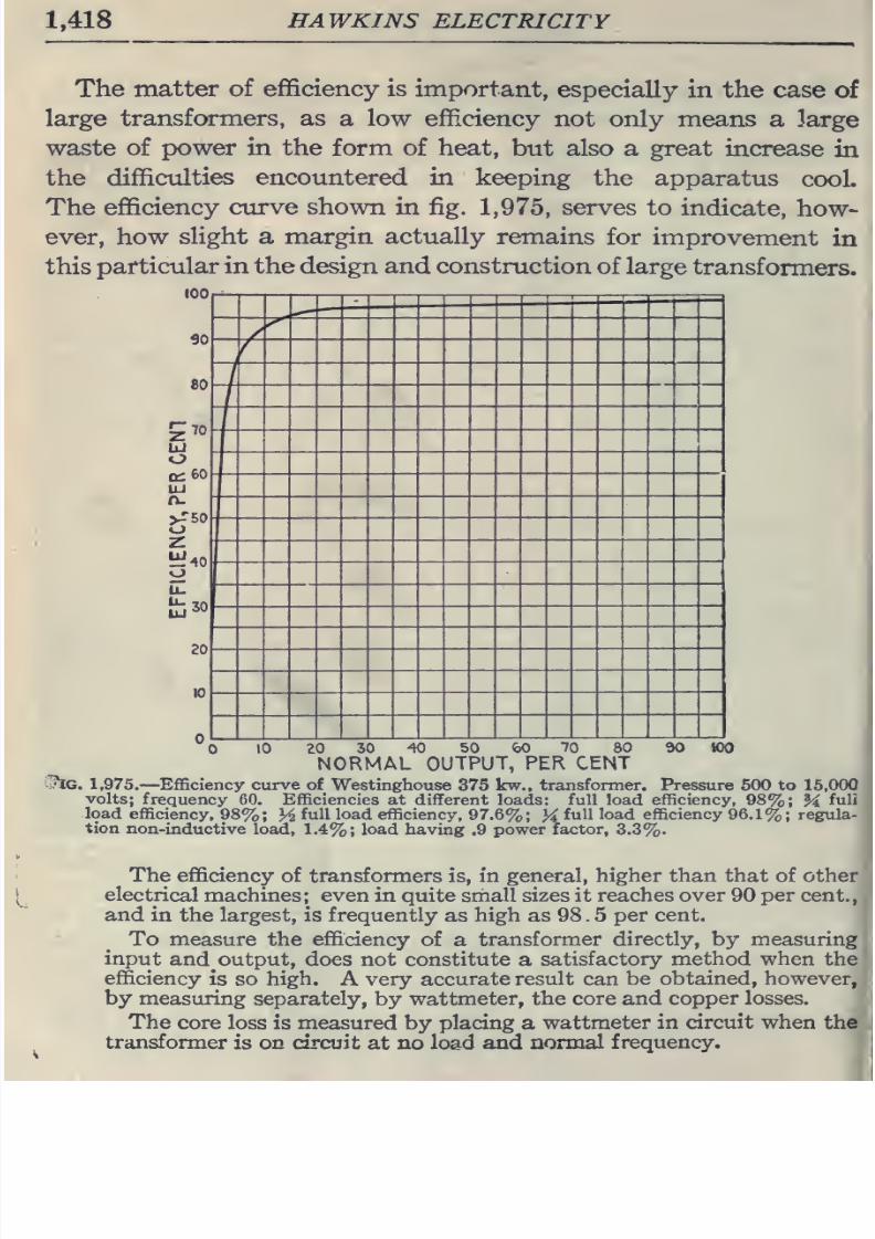
8/20/2019 electrical guide 5.pdf
http://slidepdf.com/reader/full/electrical-guide-5pdf 164/343
1,418
HAWKINS
ELECTRICITY
The
matter of
efficiency
is
important,
especially
in the
case
of
large
transformers, as
a low
efficiency
not
only
means
a
large
waste
of
power
in the
form
of
heat,
but
also
a
great
increase
in
the
difficulties
encountered in
keeping
the
apparatus
cooL
The efficiency
curve shown
in fig.
1,975,
serves
to
indicate,
how-
ever,
how
slight
a margin
actually
remains
for
improvement
in
this
particular
in
the
design and
construction
of large
transformers.
100
90
80
CcBO
UJ
n-
20
/
8/20/2019 electrical guide 5.pdf
http://slidepdf.com/reader/full/electrical-guide-5pdf 165/343
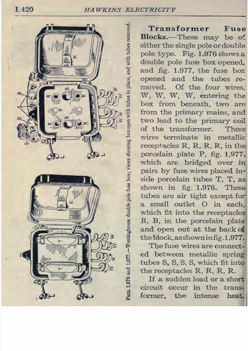
8/20/2019 electrical guide 5.pdf
http://slidepdf.com/reader/full/electrical-guide-5pdf 166/343
1.420
HAWKINS
ELECTRICITY
Transformer
Fuse
Blocks.
—
These
may
be o^
either
the single
pole
or
double
pole
type.
Fig.
1,976
shows a
double
pole fuse
box opened,
and
fig.
1,977,
the
fuse
box
opened
and the
tubes
re-
moved.
Of the
four
wires,
W,
W, W,
W,
entering
the
box
from
beneath,
two
are
from
the
primary
mains,
and
two
lead
to the
primary
coil
of
the
transformer.
These
wires
terminate
in
metallic
receptacles
R, R,
R, R,
in
the
porcelain
plate
P,
fig.
1,977,
which
are
bridged
over in
pairs
by
fuse wires
placed
in-
side
porcelain
tubes
T,
T,
as
shown in
fig.
1,976.
These
tubes are air
tight
except
for
a
small
outlet
O
in
each,
which
fit
into
the
receptacles
B, B, in the
porcelain
plate
and open out at
the
back
of
theblock, as
shown
infig,
1,977.
The fuse wires
are
connect-
ed
between
metallic
spring
tubes
S,
S,
S,
S,
which
fit into
:
the receptacles R, R,
R,
R.
1
If a sudden
load
or
a
short
circuit occur
in the
trans-
:
former,
the
intense
heat,
,;
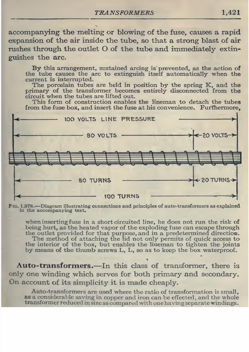
8/20/2019 electrical guide 5.pdf
http://slidepdf.com/reader/full/electrical-guide-5pdf 167/343
TRANSFORMERS
1,421
accompanying the melting or
blowing
of the
fuse,
causes a rapid
expansion of
the
air
inside
the
tube, so that
a
strong
blast of
air
rushes
through the
outlet
O
of
the
tube
and
immediately
extin-
guishes
the arc.
By
this arrangement,
sustained arcing
is prevented,
as
the
action
of
the
tube
causes
the
arc
to
extinguish
itself automatically
when
the
current
is
interrupted.
The
porcelain
tubes
are held
in position by the
spring
K,
and
the
primary of the
transformer
becomes entirely
disconnected from
the
circuit
when
the
tubes
are
lifted
out.
This
form
of
construction
enables
the lineman
to
detach
the
tubes
from
the
fuse
box,
and
insert
the
fuse
at
his
convenience.
Furthermore,
too
VOLTS
LlNt
PRESSURE
80 VOLTS
><-eO
VOLTS-
BO
TURNS
>-<-20TURNS->
100
TURNS
Pig.
1,978,
—
Diagram
illustrating
connections
and
principles
of
auto-transformers
as explained
in
the accompanying
text.
when
inserting
fuse
in
a
short circuited
line,
he
does
not run the risk of
being
hurt,
as
the
heated vapor of the
exploding fuse
can escape
through
the outlet
provided
for that purpose,
and
in
a
predetermined
direction.
The
method of attaching
the lid not
only
permits
of
quick
access
to
the interior
of the
box,
but enables
the lineman to
tighten
the joints
by
means
of
the
thumb
screws
L,
L,
so
as
to keep the box
waterproof.
Auto-
transformers.
—
In
this
class
of
transformer,
there
is
C)nly
one
winding
which serves
for both
primary
and
secondary.
On
accotint
of
its simplicity it is made cheaply.
Auto-transformers
are
used
where the ratio
of
transformation
is small,
as a considerable
saving
in
copper
and iron
can
be
effected,
and
the
whole
transformer
reduced
in
size
as
compared with
one
having
separate
windings.
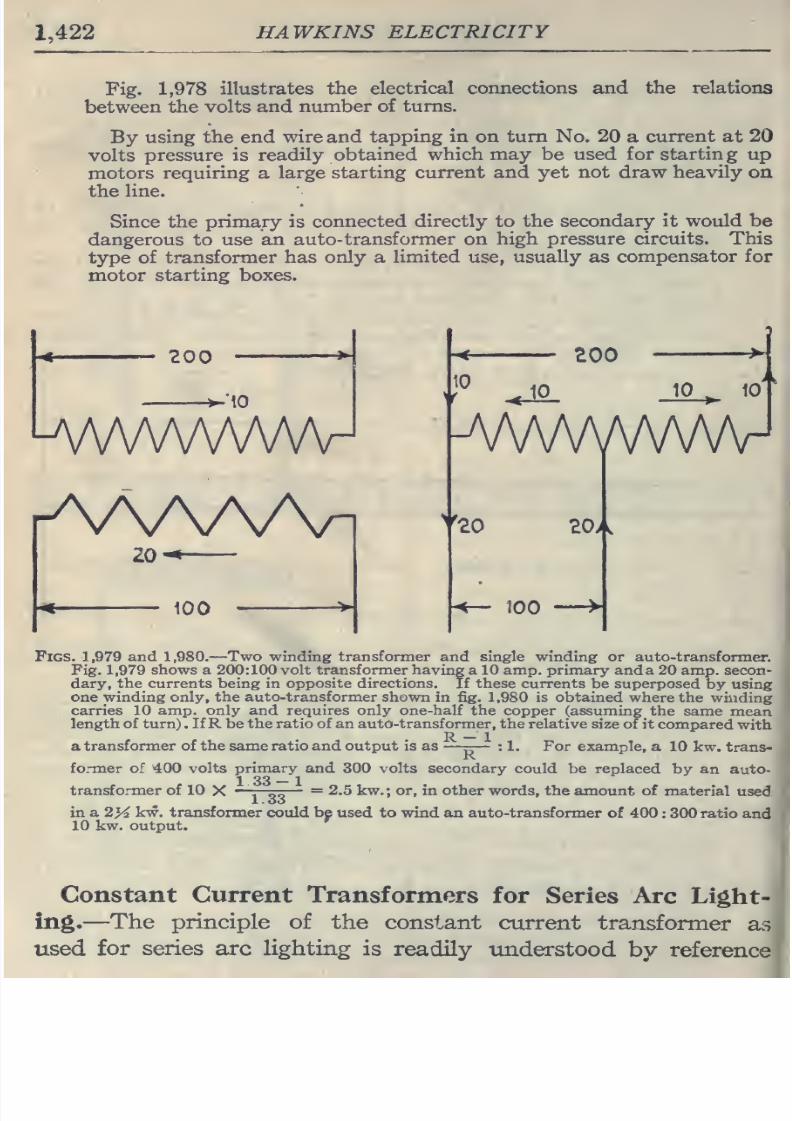
8/20/2019 electrical guide 5.pdf
http://slidepdf.com/reader/full/electrical-guide-5pdf 168/343
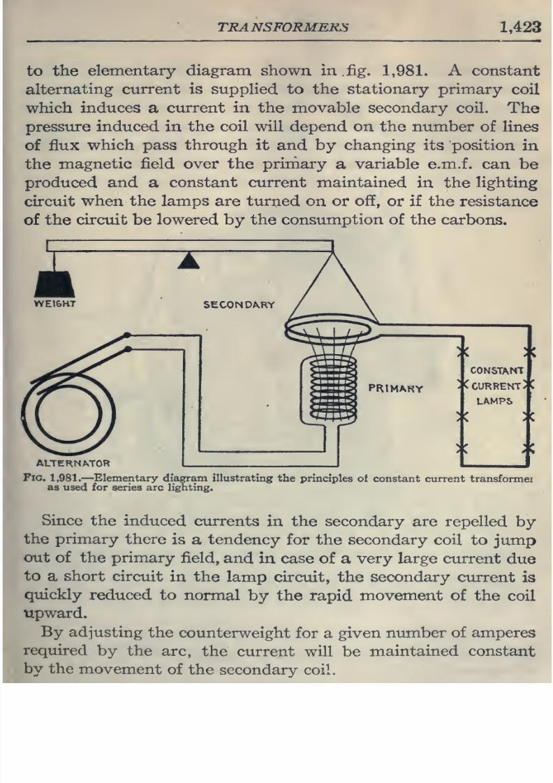
8/20/2019 electrical guide 5.pdf
http://slidepdf.com/reader/full/electrical-guide-5pdf 169/343
transformek:s
1,423
to
the
elementary diagram shown
in.
fig.
1,981. A
constant
alternating
current is
supplied to the
stationary
primary
coil
which
induces
a
current
in
the
movable secondary coil.
The
pressure induced
in
the
coil will
depend
on the
number
of lines
of
flux
which
pass
through it
and
by
changing
its position
in
the
magnetic
field
over
the
priniary
a
variable
e.m.f.
can
be
produced
and
a
constant
current
maintained
in the
lighting
circuit
when the
lamps
are
turned
on
or
off, or
if the
resistance
of
the
circuit
be
lowered
by
the
consumption of the
carbons.
CONSTANT
PRIMARY
^
CURRENT^
I
LAMPS
ALTERNATOR
Fig.
1,981.
—
Elementary
diagram
illustrating
the
principles
of
constant
current transformei
as used for series arc
lighting.
Since
the
induced
currents
in the secondary are
repelled
by
the
primary
there
is
a tendency
for the
secondary
coil
to
jump
out
of the primary
field,
and
in
case
of a
very large
current
due
to
a
short
circuit
in the
lamp
circuit, the
secondary
current
is
quickly
reduced
to
normal
by
the
rapid
movement
of
the
coil
upward.
By
adjusting
the
counterweight
for a
given
number
of
amperes
required
by
the
arc,
the
current will
be
maintained
constant
by
the
movement
of
the
secondary coil.
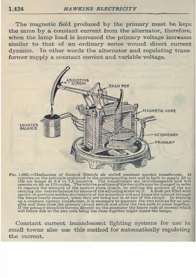
8/20/2019 electrical guide 5.pdf
http://slidepdf.com/reader/full/electrical-guide-5pdf 170/343
1,424
HAWKINS
ELECTRICITY
The
magnetic
field
produced
by
the
primary
must
be
kept
the
same
by
a
constant
current
from
the
alternator,
therefore,
when
the
lamp
load
is increased
the
primary
voltage
increases
similar
to
that
of an
ordinary series
wound
direct
current
dynamo.
In
other
words the
alternator
and
regulating
trans-
former
supply a constant current
and
variable voltage.
DASH
POT
MAGNETIC
CORE
Pig.
1,982.
—
Mechanism of
General
Electric
air
cooled
constant
current transformer.
It
operates on the
principle
explained
in the
accompanying
text and
is
built
to
supply
25
to
100
arc
lamps
at
6.6
to
7.5
amperes.
The
transformers
are interchangeable and
will
operate on
60
or
125
cycles. The
relative
positions
of
the
two
coils
may
be
changed
in order
to
regulate
the
strength
of the
current
more
closely,
by
shifting
the
position
of
the
arc
carrying
the counterbalance
by means
of the adjusting
screw on it.
A
dash pot
filled
with
special oil
prevents
sudden
movements
of the
secondary coil
and
keeps
the
current
through
the
lamps
nearly constant, when they
are
being cut in
or
out
of
the
circuit.
In starting
up
a
constant
current transformer, it
is necessary
to separate
the two coils
as
far as
pos-
sible and
then
close
the
primary
circuit
switch
and
allow
the
two coils to
come together.
If
the primary circuitbe thrown
directly
on
the generator
the heavy rush
of current
which
will
follow
due
to the
two
coils
being
too
close
together
might
injure
the
lamps.
Constant current
incandescent
lighting
systems
for
use
in
small
towns
also
use
this
method
for
automatically
regulating
the
current.
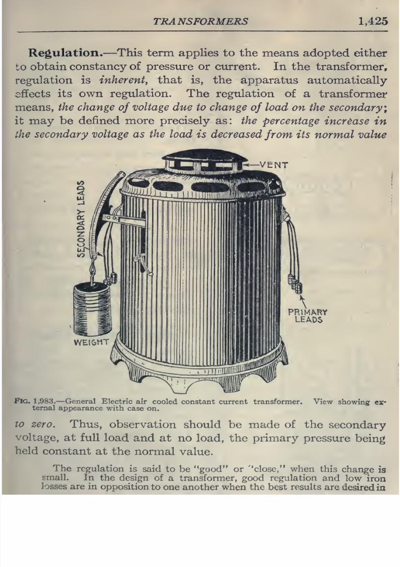
8/20/2019 electrical guide 5.pdf
http://slidepdf.com/reader/full/electrical-guide-5pdf 171/343
TRANSFORMERS
1,425
Regulation.
—
This
term applies
to the
means
adopted
either
to
obtain
constancy
of
pressure or
current.
In
the
transformer,
regulation
is
inherent,
that is,
the apparatus automatically
effects
its
own
regulation.
The regulation
of
a
transformer
means,
the change
of
voltage
due
to
change
of
load
on the
secondary;
it may
be
defined
more precisely
as:
the
percentage
increase in
the
secondary voltage
as
the
load is decreased
from
its normal
value
VENT
\
PRlMAvRY
LEADS
Fig. 1,983.
—
General
Electric
air
cooled constant
current
transformer,
teraal
appearance
with
case
on.
View
showing
ex*
10
zero.
Thus,
observation
should
be made
of
the
secondary
voltage,
at
full
load and
at no load,
the
primary
pressure
being
held
constant
at the
normal
value.
The
regulation
is
said
to be '*good
or
''close, when
this
change
is
small.
In
the design
of
a
transformer,
good
regulation
and
low
iron
losses are
in
opposition
to
one another
when
the best
results
are
desired
in
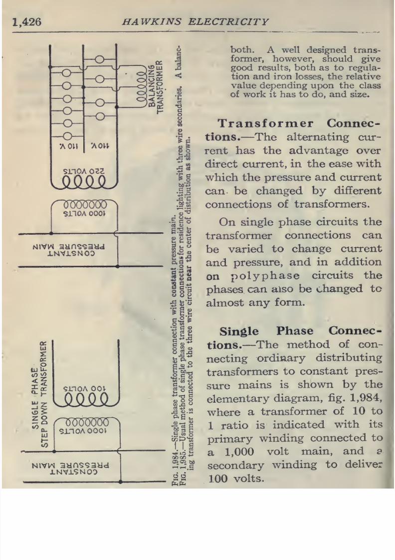
8/20/2019 electrical guide 5.pdf
http://slidepdf.com/reader/full/electrical-guide-5pdf 172/343
1,426
HAWKINS
ELECTRICITY
snoA
oil
SilOA
0001
Mivw
aanQsaad
Ul
•s:
iuU-
Si
9L10A
OOV
smoAooov
NivvN
aHns93ya
1NV19NO0
1^
TO
lU
.
**
2
^
gtJS
88S
O
tfl
y
rt
«
oj
'-'
i3
^
u^
O
I
0)
2
O
G
Ttl
00
00
05 0>
bfl
both.
A
well designed trans-
former, however,
should give
good results,
both
as
to
regula-
tion
and iron
losses,
the
relative
value
depending
upon
the^ class
of
work it
has
to
do, and size.
Transformer
Connec-
tions.—The
alternating
cur-
rent
has the
advantage
over
direct
current,
in
the
ease
with
which the
pressure
and
current
can be
changed
by different
connections
of
transformers.
On
single
phase circuits the
transformer
connections
can
be
varied
to
change
current
and
pressure,
and
in
addition
on
polyphase
circuits
the
phases,
can
also
be
changed
tc
almost
any
form.
Single
Phase
Connec-
tions.
—
The
method
of
con-
necting
ordinary
distributing
transformers
to
constant
pres-
sure
mains
is
shown
by
the
elementary
diagram,
fig.
1,984,
where
a
transformer
of
10
to
1
ratio
is
indicated
with
its
primary
winding
connected
to
a
1,000
volt
main,
and
a
secondary
winding
to
deliver
100
volts.
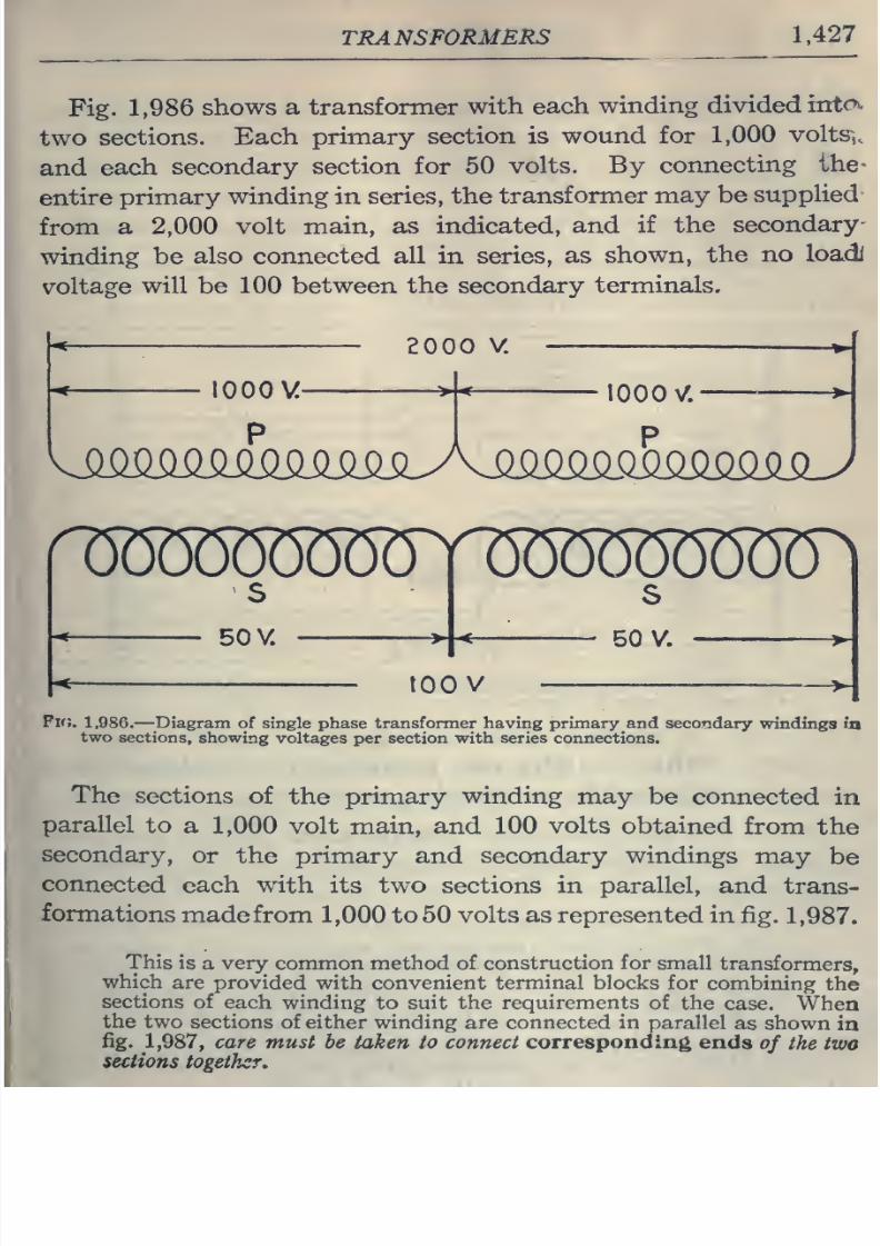
8/20/2019 electrical guide 5.pdf
http://slidepdf.com/reader/full/electrical-guide-5pdf 173/343
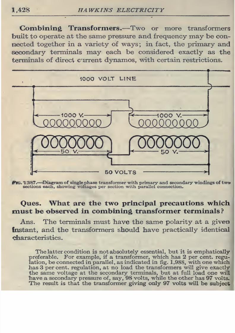
8/20/2019 electrical guide 5.pdf
http://slidepdf.com/reader/full/electrical-guide-5pdf 174/343
1,428
HAWKINS
ELECTRICITY
Combining
Transformers.
—Two
or more
transformers
built
to
operate
at the
same
pressure
and frequency
may
be
con-
nected
together
in
a
variety of
ways;
in
fact,
the
primary
and
secondary
terminals
may
each
be
considered
exactly
as
the
terminals
of direct
cirrent
dynamos,
with
certain
restrictions.
1000
VOLT
LINE
KsmoQ^
1000 V. A
[<
1000
V.
^
-
<
50
V.
C
^
^^
^'
*'
50 VOLTS
ftG.1^7.
—
(Diagram of single phase transformer with
primary
and
secondary
windings
of two
sections
each,
showing voltages
per
section
with
parallel
connection.
Ones.
What
are
the
two
principal
precautions
which
must be
observed
in combining
transformer
terminals
?
Ans.
The
terminals
must have
the
same
polarity
at
a
given
Instant,
and
the
transformers
should
have
practically
identical
^aracteristics.
The
latter
condition
is not
absolutely
essential, but
it
is
emphatically
preferable. For
example, if
a
transformer,
which
has
2
per cent, regu-
lation, be
connected in
parallel,
as
indicated in
fig.
1,988,
with one
which
has
3
per cent,
regulation, at no load
the
transformers
will
give
exactly
the same
voltage
at
the secondary
terminals,
but
at
full
load
one will
liave
a
secondary
pressure
of,
say,
98
volts, while
the other
has
97
volts.
The result is that the
transformer giving
only
97 volts
will
be
subject
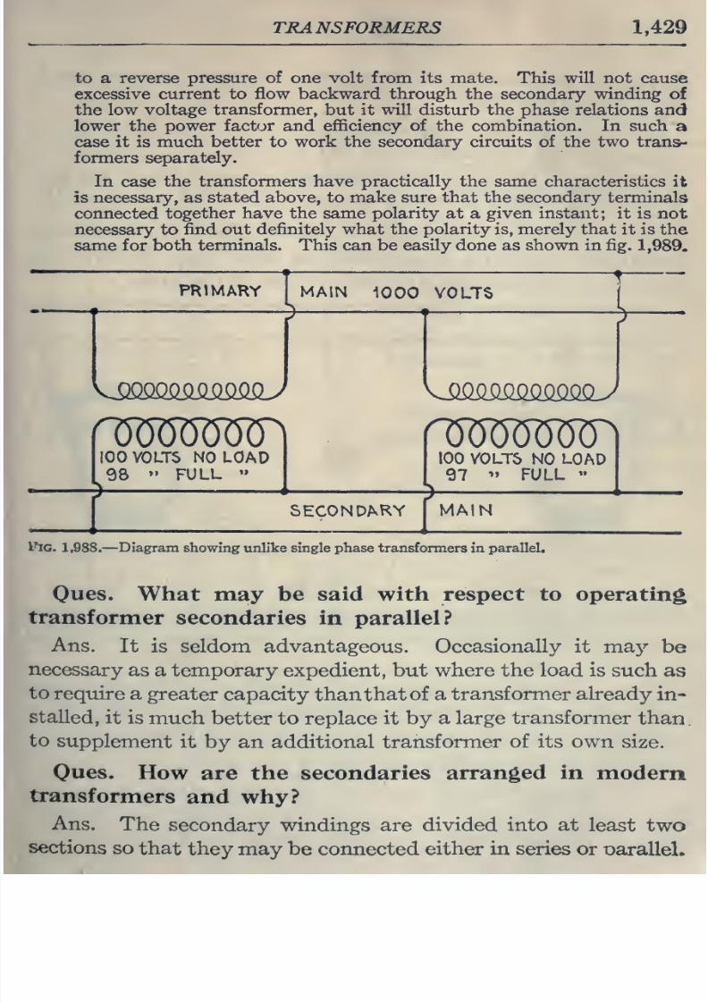
8/20/2019 electrical guide 5.pdf
http://slidepdf.com/reader/full/electrical-guide-5pdf 175/343
TRANSFORMERS
1,429
to
a
reverse pressure of one volt from its
mate. This
will
not
cause
excessive
current
to
flow
backward through
the secondary
winding
of
the low
voltage
transformer,
but
it will
disturb
the
phase relations
and
lower the power factor and
efficiency
of
the combination. In such
a
case it
is much better
to
work
the
secondary circuits
of the
two trans-
formers separately.
In case
the transformers have practically the
same
characteristics it
is necessary,
as
stated
above,
to
make
sure
that the
secondary
terminals
connected
together have
the same
polarity
at
a
given instant;
it
is not
necessary
to
find
out
definitely what
the
polarity
is,
merely
that
it is the
same
for
both
terminals.
This
can be
easily
done
as
shown in
fig.
1,989.
PRIMARY
MAIN
1000
VOLTS
^
100
VOLTS
NO
LOAD
98
••
FULL
100
VOLTS
NO
LOAD
97
'>
FULL
»
SECONDARY
MAIN
ftc.
1,988.—Diagram
showing
unlike single phase
transformers in
parallel.
Oues.
What
may be
said
with
respect
to
operating
transformer
secondaries
in
parallel?
Ans.
It
is
seldom
advantageous.
Occasionally
it
ma}'-
be
necessary
as
a temporary
expedient,
but
where
the load
is
such
as
to
require
a
greater capacity
than
that of
a transformer already
in-
stalled,
it is
much
better to replace
it
by
a
large
transformer
than,
to
supplement
it
by an additional
transformer
of its
own
size.
Oues.
How
are
the
secondaries
arranged
in
modern
transformers
and
why?
Ans.
The
secondary
windings
are
divided into at
least
two
sections
so
that
they may
be
connected
either
in
series
or
oaralleL
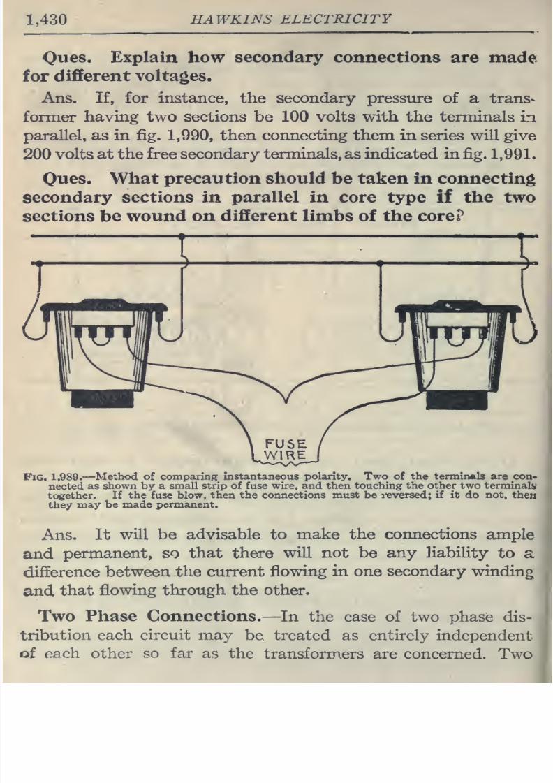
8/20/2019 electrical guide 5.pdf
http://slidepdf.com/reader/full/electrical-guide-5pdf 176/343
1,430
HAWKINS
ELECTRICITY
Ones.
Explain
how
secondary
connections
are
made
for
different
voltages.
Ans.
If,
for
instance,
the
secondary presstire
of
a
trans-
former
having
two
sections
be
100
volts
with
the
terminals
in
parallel,
as
in fig.
1,990,
then connecting them
in
series will
give
200
volts at the
free
secondary terminals,
as
indicated
in
fig.
1,991.
Ones.
What
precaution
should
be
taken
in
connecting
secondary
sections
in
parallel
in
core
type
if
the two
sections
be
wound on
different
limbs
of the
core?
Fig.
1,989.
—
Method
of
comparing
instantaneous
polarity.
Two
of
the
terminals are
con-
nected
as
shown
by a
small strip of fuse wire,
and
then
touching
the
other
two
terminals
together.
If
the fuse
blow,
then the
connections
must
be
i-eversed;
if
it
do
not,
then
they
may be
made permanent.
Ans.
It
will be
advisable
to
make
the
connections
ample
and
permanent,
so
that
there
will
not
be
any
liabiHty
to
a
difference
between the
current
flowing
in
one secondary
winding
and
that
flowing
through
the
other.
Two
Phase Connections.
—In
the
case
of
two
phase dis-
tribution
each
circuit
may
be treated
as
entirely
independent
of
each
other
so far
as
the
transformers
are
concerned.
Two
I
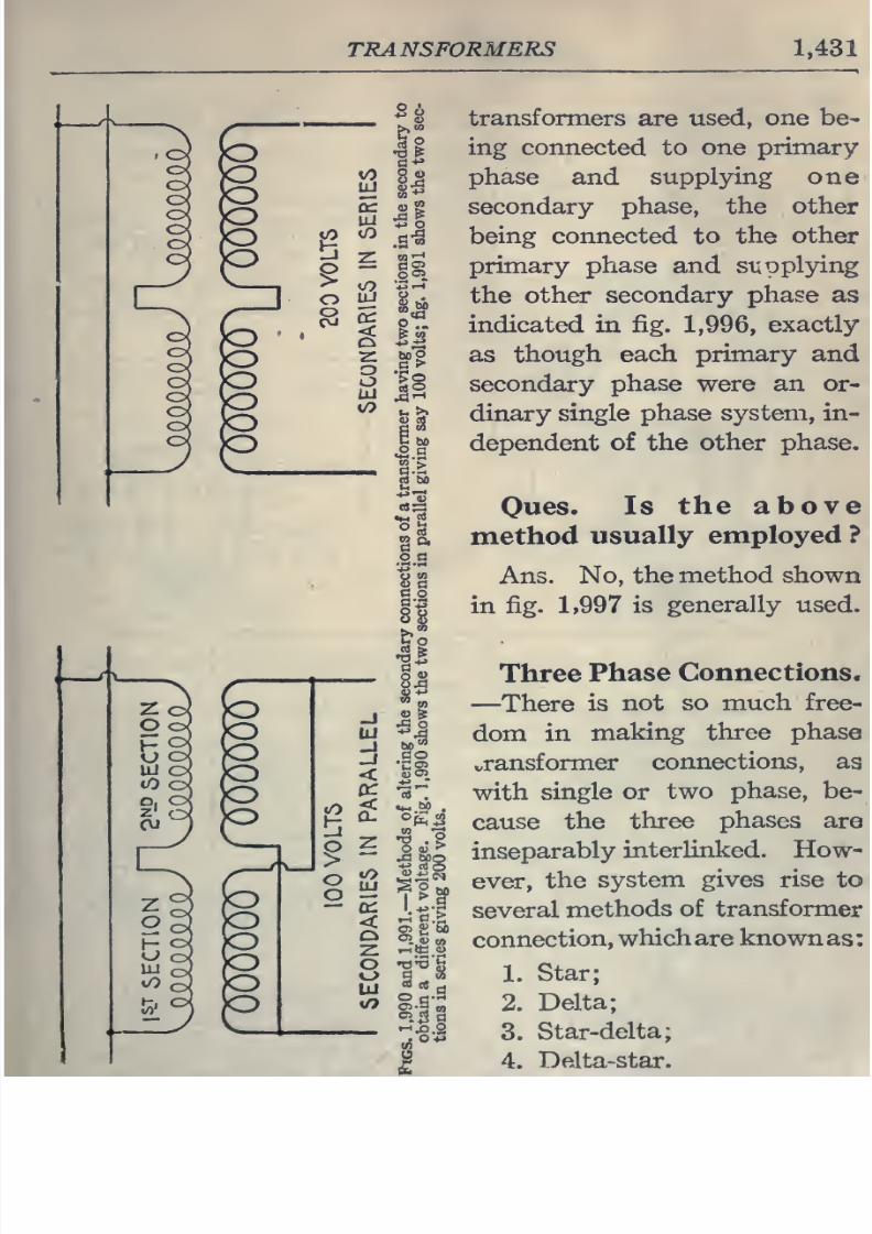
8/20/2019 electrical guide 5.pdf
http://slidepdf.com/reader/full/electrical-guide-5pdf 177/343
TRANSFORMERS
1,431
transformers
are
used,
one
be-
ing
connected
to
one
primary
phase
and
supplying
one
secondary
phase, the
other
being connected
to
the
other
primary
phase
and
supplying
the
other
secondary
phase as
indicated
in
fig.
1,996,
exactly
as
though each
primary and
secondary
phase were
an
or-
dinary
single
phase system, in-
dependent
of the
other
phase.
Oues.
Is
the above
method
usually
employed ?
Ans.
No,
the
method
shown
in fig. 1,997
is
generally
used.
Three
Phase
Connections.
—
There
is
not
so
much
free-
dom in
making three
phase
t,ransformer
connections,
as
with
single or
two
phase,
be-
cause
the
three
phases
are
inseparably
interlinked. How-
ever,
the
system
gives rise
to
several
methods
of
transformer
connection,
which
are
known
as:
1.
Star;
2.
Delta;
3.
Star-delta;
4.
Delta-star.
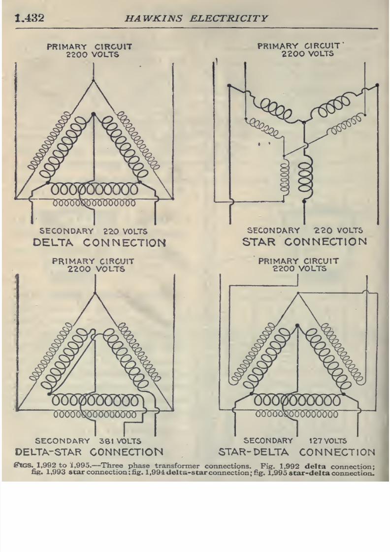
8/20/2019 electrical guide 5.pdf
http://slidepdf.com/reader/full/electrical-guide-5pdf 178/343
1,432
HAWKINS
ELECTRICITY
PRIMARY CIRCUIT
2200
VOLTS
PRIMARY
CIRCUIT
2200
VOLTS
SECONDARY
220 VOLTS
DELTA
CONNECTION
SECONDARY 220
VOLTS
STAR
CONNECTION
PRIMARY
CIRCUIT
2200
VOLTS
PRIMARY
CIRCUIT
2200
VOLTS
SECONDARY
381
VOLTS
DELTA-STAR
CONNECTION
SECONDARY
127
VOLTS
STAR-DELTA
CONNECTION
^rcs.
1,992
to
1,995.
—
Three
phase
transformer
connections.
Fig.
1,992 delta
connection;
fig.
1,993
star
connection; fig.
1,994
delta-star
connection; fig.
1,995 star-delta
connectioiu
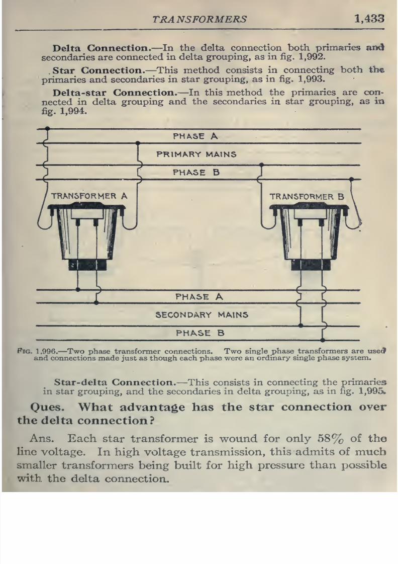
8/20/2019 electrical guide 5.pdf
http://slidepdf.com/reader/full/electrical-guide-5pdf 179/343
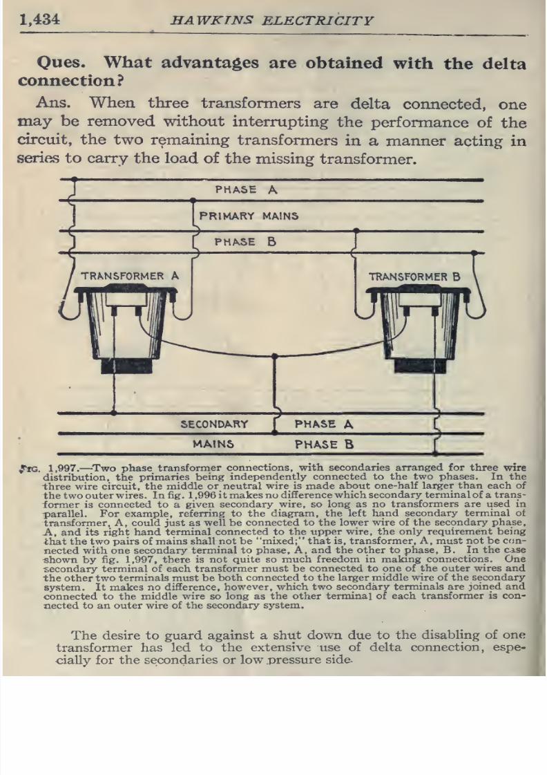
8/20/2019 electrical guide 5.pdf
http://slidepdf.com/reader/full/electrical-guide-5pdf 180/343
1,434
HAWKINS
ELECTRICITY
Oues.
What
advantages
are
obtained
with
the delta
connection?
Ans.
When three
transformers
are
delta
connected,
one
may
be
removed
without
interrupting
the
performance
of
the
circuit,
the two remaining
transformers
in
a
manner
acting
in
series
to
carry
the load of
the missing
transformer.
PHASE
A
PRIMARY MAINS
J^tG.
1,997,
—
^Two
phase
transformer
connections,
with
secondaries
arranged
for
three
wire
distribution, the
primaries
being
independently
connected to
the
two
phases.
In
the
three
wire
circuit,
the
middle
or
neutral
wire
is
made about
one-half
larger than
each
of
the two
outer
wires. In fig.
1
,996 it makes no
difference which
secondary
terminal of
a
trans-
former
is
connected
to
a
given
secondary wire, so
long
as
no transformers
are
used in
parallel. For
example,
referring
to the
diagram,
the
left
hand
secondary terminal ot
transformer,
A,
could
just
as
well
be
connected
to
the
lower
wire of
the
secondary
phase,
A,
and its
right hand terminal
connected
to
the upper wire,
the
only requirement
being
ihat
the
two
pairs of
mains
shall not be
mixed; that is,
transformer.
A, must not be
con-
nected with
one
secondary
terminal to
phase. A,
and the other to
phase,
B. In the
case
shown
by
fig.
1,997,
there
is
not
quite
so
much
freedom
in
making
connections.
One
secondary
terminal of each
transformer must be
connected
to one of
the
outer
wires
and
the other
two
terminals
must
be
both
connected
to the larger
middle
wire
of the
secondary
system. It
makes
no
difference, however,
which
two
secondary
terminals
are
joined
and
connected to the
middle
wire so
long
as
the other terminal of each
transformer is
con-
nected to
an outer
wire
of the secondary
system.
The desire to
guard against a
shut
down
due
to
the
disabling of one
transformer has led
to
the
extensive
use of delta
connection,
espe-
cially for
the
secondaries
or
low .pressure
side-
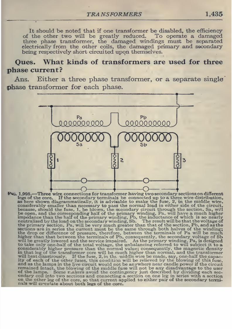
8/20/2019 electrical guide 5.pdf
http://slidepdf.com/reader/full/electrical-guide-5pdf 181/343
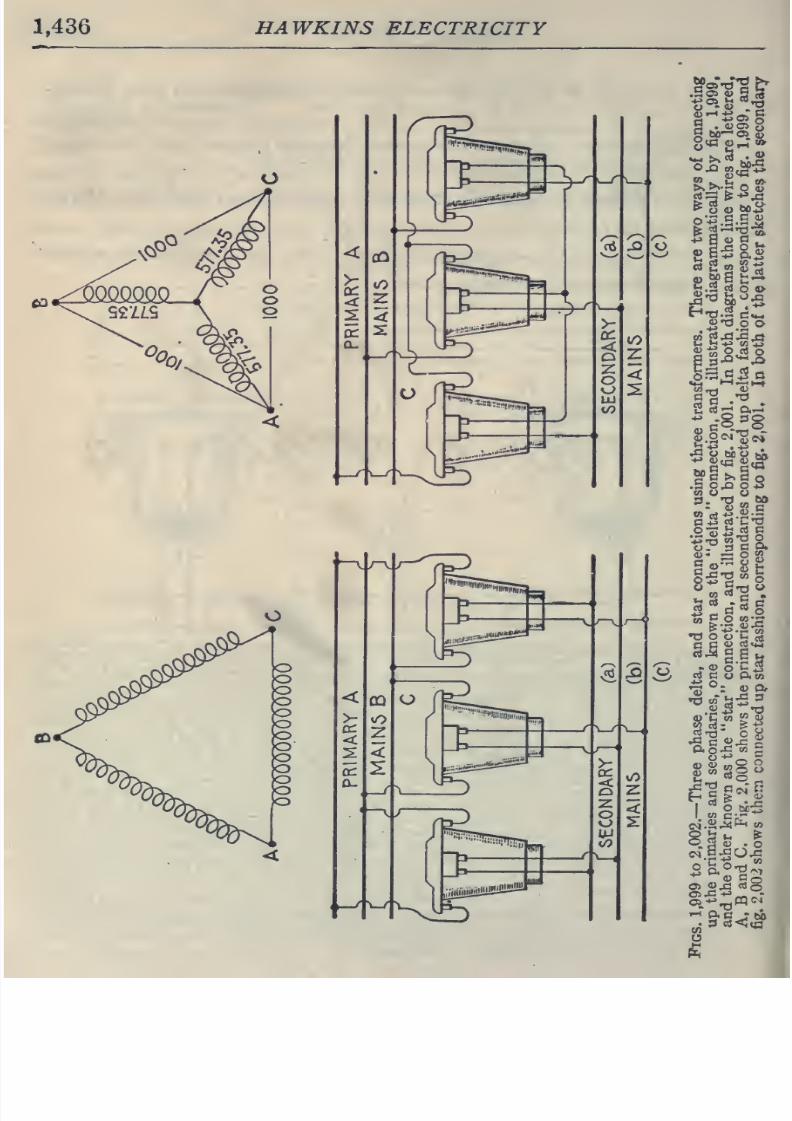
8/20/2019 electrical guide 5.pdf
http://slidepdf.com/reader/full/electrical-guide-5pdf 182/343
1,436 HAWKINS
ELECTRICITY
5==li
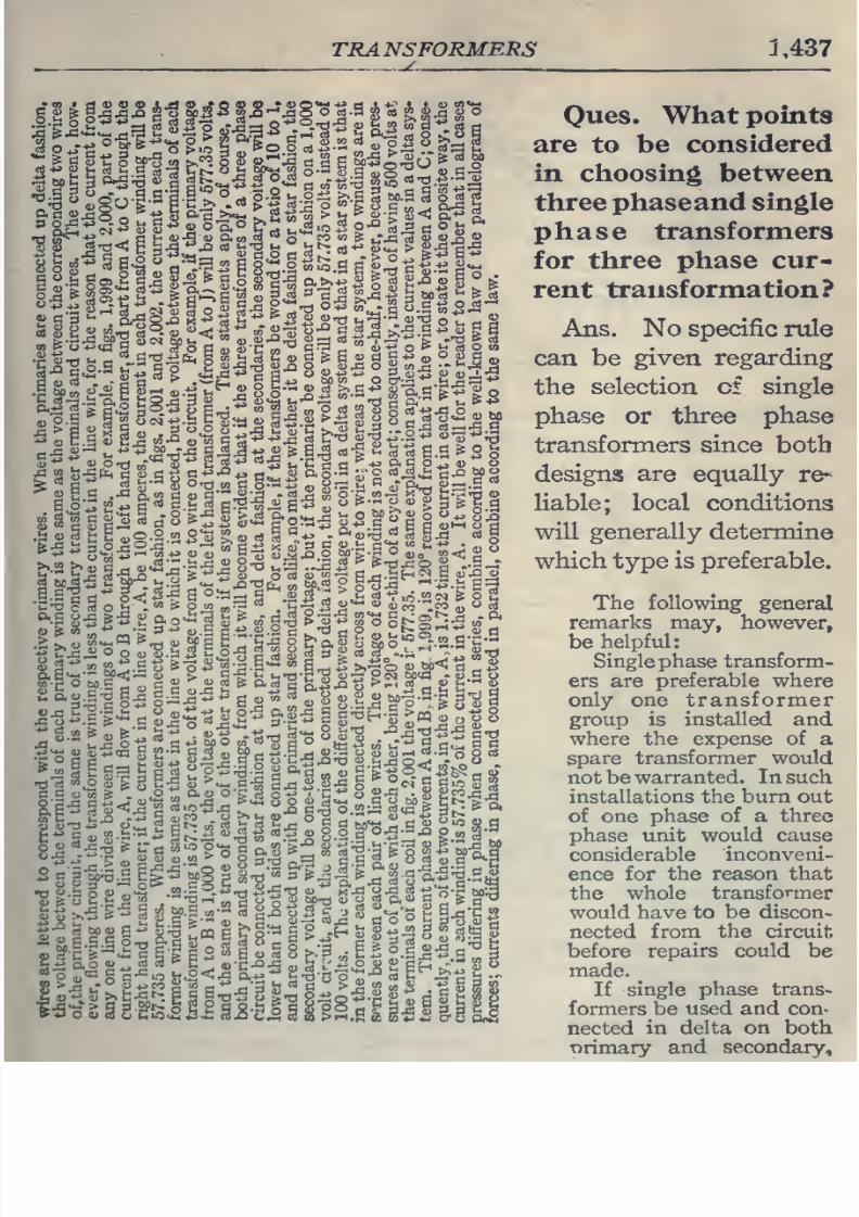
8/20/2019 electrical guide 5.pdf
http://slidepdf.com/reader/full/electrical-guide-5pdf 183/343
TRANSFORMERS
1,437
-
.—
^
-^CCSCS
rt
Ques.
What
points
-
i^l
t
i
^^
S
i^
i
Z^-r.n
alllo
^^
&
f'^^
^ ^
^?
considered
lii
§
Ui
II
IslirS^
r:ilil1lial
i^
choosing
between
three phaseand
single
phase
transformers
for
three
phase cur-
rent
transformation?
Ans.
No specific
rule
can
be
given
regarding
the
selection of single
phase
or
three
phase
transformers since
both
I
S
l^ -
g
S.S5
§--S^
gaS
^§5
s
§
--1*
S^JS
designs
are
equaUy
re-
'leSl illilli§.^ir rislr^1l
liable;
local
conditions
will
generally
determine
which
type
is
preferable.
The following
general
remarks
may,
however,
be
helpful:
1
1--^
«
°
S^ll^'^ll^
i
1^1
^;§°J'^
.b<J^
ZJ
Singlephase transform-
S'I'msI'';
^^ ^i ^
all-gala's
>^.
T^
gl--
« ers
are
preferable
where
^^§l1p:2o^|^::a^^^«§8.^^^|-2;gg|g
only one
transformer
group
is
installed and
where
the expense
of
a
spare
transformer would
not
be
warranted.
In
such
installations
the
burn
out
of
one
phase
of
a
three
phase
unit
would cause
considerable
inconveni-
ence for
the
reason that
the
whole
transformer
would have
to
be discon-
^^^-
-^3M a.
..:=,
u
nected
from
the
circuit
|IS^e^S8b3,^HB°l^:S.«'^§
before
repairs could
be
made.
l?i
litsll
Slllll
rt%ul
ill
li
II
formers.be
4d
and con-
nected m
delta
on both
t)rimary
and
secondary.
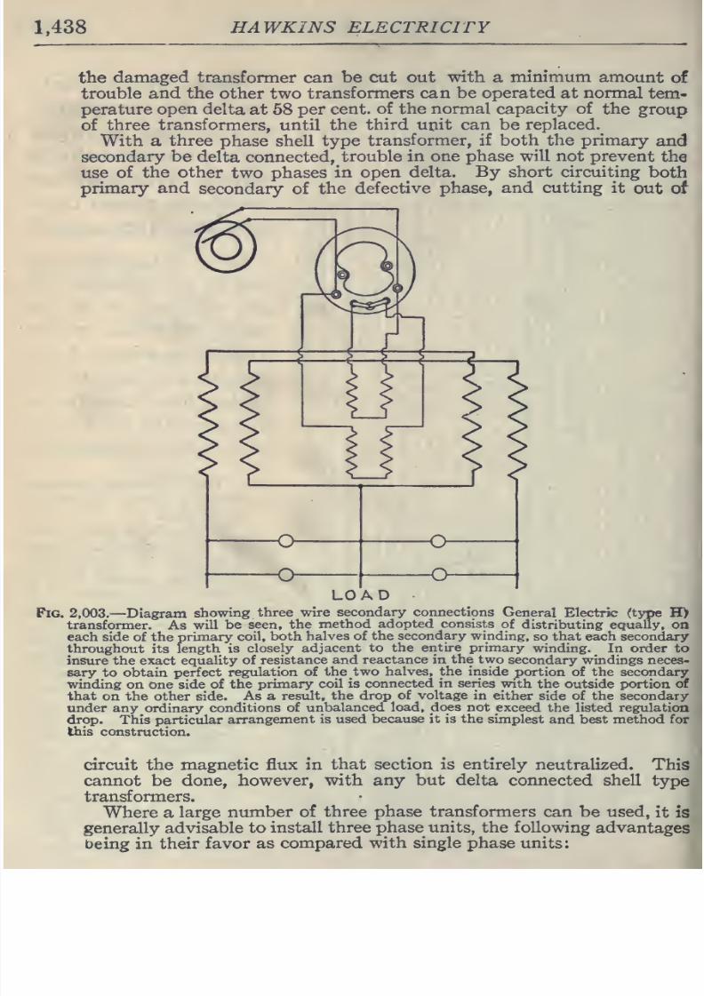
8/20/2019 electrical guide 5.pdf
http://slidepdf.com/reader/full/electrical-guide-5pdf 184/343
1.438
HAWKINS ELECTRICITY
the
damaged
transformer
can
be cut
out
with
a
minimum
amount
of
trouble
and
the
other
two
transformers can
be
operated
at normal
tem-
perature
open
delta
at
58
per
cent,
of
the normal
capacity
of
the
group
of
three
transformers,
until
the
third
upit
can
be
replaced.
With a
three
phase
shell
type
transformer, if
both
the
primary
and
secondary be
delta
connected,
trouble
in one
phase
will not prevent
the
use
of
the
other
two phases
in
open
delta. By
short
circuiting
both
primary
and
secondary of
the
defective phase,
and
cutting
it
out of
LOAD
Fig.
2,003.
—
Diagram
showing
three wire
secondary
connections
General
Electric (type
H>
transformer.
As
will
be
seen,
the
method
adopted
consists
of
distributing equally,
on
each
side
of
the
primary
coil,
both
halves
of the
secondary winding,
so
that
each
secondary
throughout
its
length
is
closely
adjacent to
the entire primary
winding.
In order to
insure
the
exact
equality
of resistance
and
reactance in
the two
secondary
windings
neces-
sary to
obtain
perfect
regulation
of
the two
halves, the
inside
portion
of
the
secondary
winding
on one side
of the
primary
coil is
connected in
series
with
the outside
portion
of
that
on
the
other side.
As
a
result,
the
drop of
voltage
in
either
side of
the
secondary
under any ordinary
conditions
of
unbalanced
load,
does
not
exceed
the
listed regulation
drop. This
particular
arrangement
is used
because it is
the
simplest
and best method for
this construction.
circuit
the
magnetic
flux in
that
section
is
entirely
neutralized.
This
cannot
be
done,
however, with
any but delta
connected
shell
type
transformers.
Where
a
large
number of
three
phase transformers
can be used,
it
is
generally
advisable
to
install
three phase
units,
the
following
advantages
Deing
in
their favor
as
compared
with single
phase units:
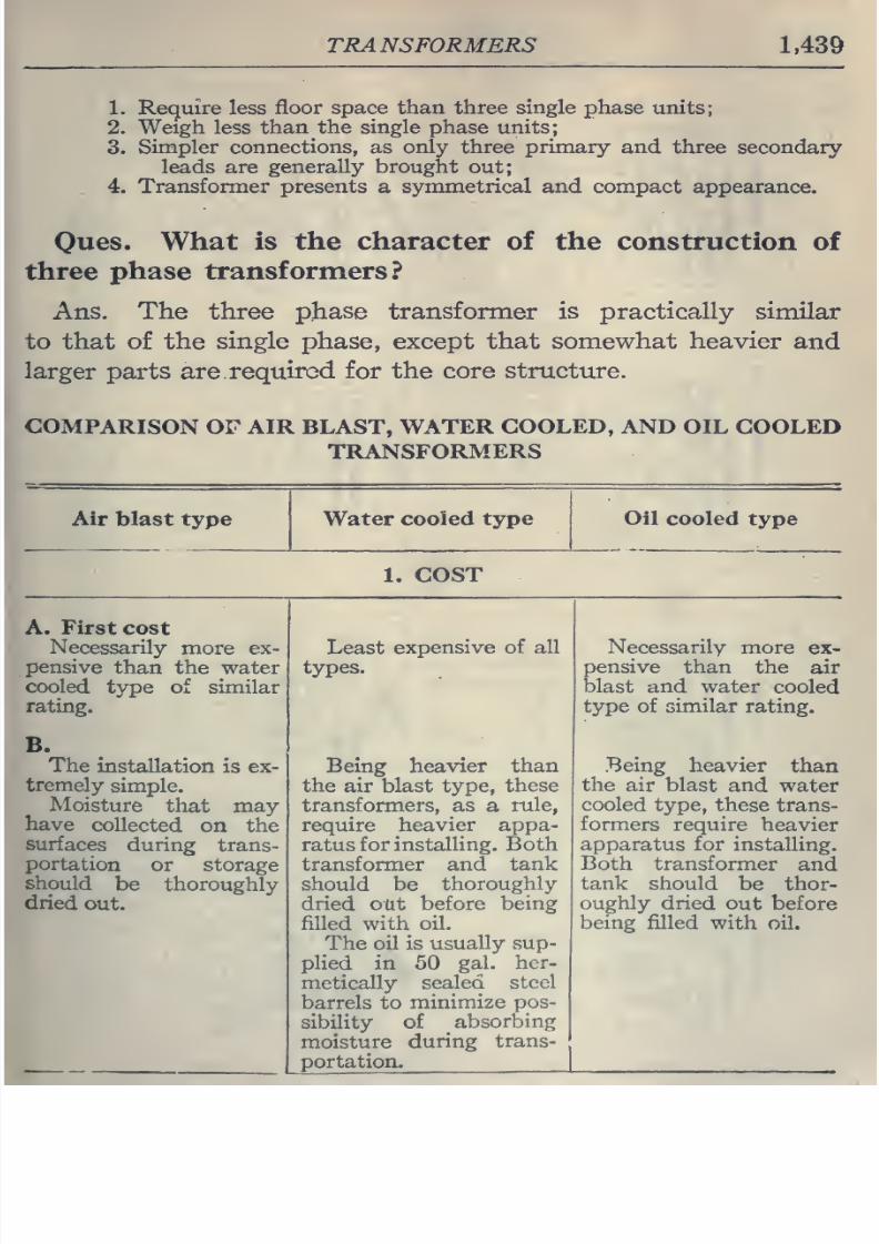
8/20/2019 electrical guide 5.pdf
http://slidepdf.com/reader/full/electrical-guide-5pdf 185/343
TRANSFORMERS
1,439
1.
Require
less
floor space
than
three
single
phase units;
2.
Weigh
less
than
the
single
phase
units;
3.
Simpler connections, as only three primary
and three
secondary
leads
are
generally brought
out;
4.
Transformer
presents
a
symmetrical
and
compact
appearance.
Oues.
What
is the
character of
the
construction
of
three
phase
transformers?
Ans.
The three
phase
transformer
is
practically
similar
to that of
the
single phase,
except
that
somewhat
heavier
and
larger
parts
are.
required
for
the
core
structure.
COMPARISON
OF
AIR
BLAST,
WATER
COOLED,
AND
OIL COOLED
TRANSFORMERS
Air blast
type
Water cooled
type
Oil
cooled
type
1.
COST
A.
First
cost
Necessarily
more
ex-
pensive
than
the water
cooled
type of
similar
rating.
B.
The
installation is ex-
tremely
simple.
Moisture
that
may
have
collected
on
the
surfaces
during
trans-
portation
or
storage
should
be thoroughly
dried
out.
Least
expensive of all
types.
Being heavier
than
the air blast type,
these
transformers,
as
a
mle,
require
heavier appa-
ratus
for
instalHng.
Both
transformer and
tank
should
be
thoroughly
dried
out
before being
filled
with
oil.
The
oil
is
usually
sup-
plied
in
50
gal.
her-
metically sealed
steel
barrels to
minimize pos-
sibility
of
^
absorbing
moisture
during
trans-
portation;^
Necessarily
more
ex-
pensive than
the
air
blast
and water
cooled
type
of
similar
rating.
Being
heavier
than
the
air blast
and
water
cooled
type, these
trans-
formers
require
heavier
apparatus for
installing.
Both
transformer
and
tank should
be thor-
oughly dried
out
before
being filled
with
oil.
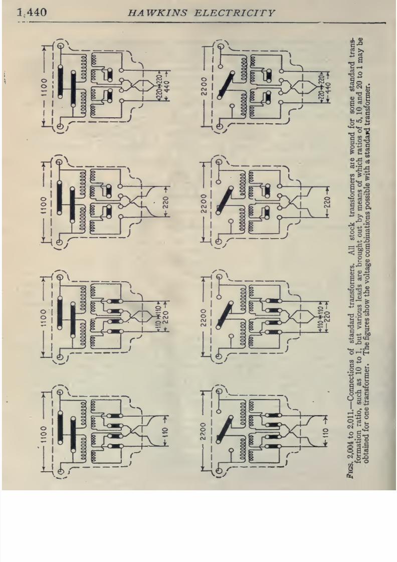
8/20/2019 electrical guide 5.pdf
http://slidepdf.com/reader/full/electrical-guide-5pdf 186/343
1440
HAWKINS ELECTRICITY
iri9\
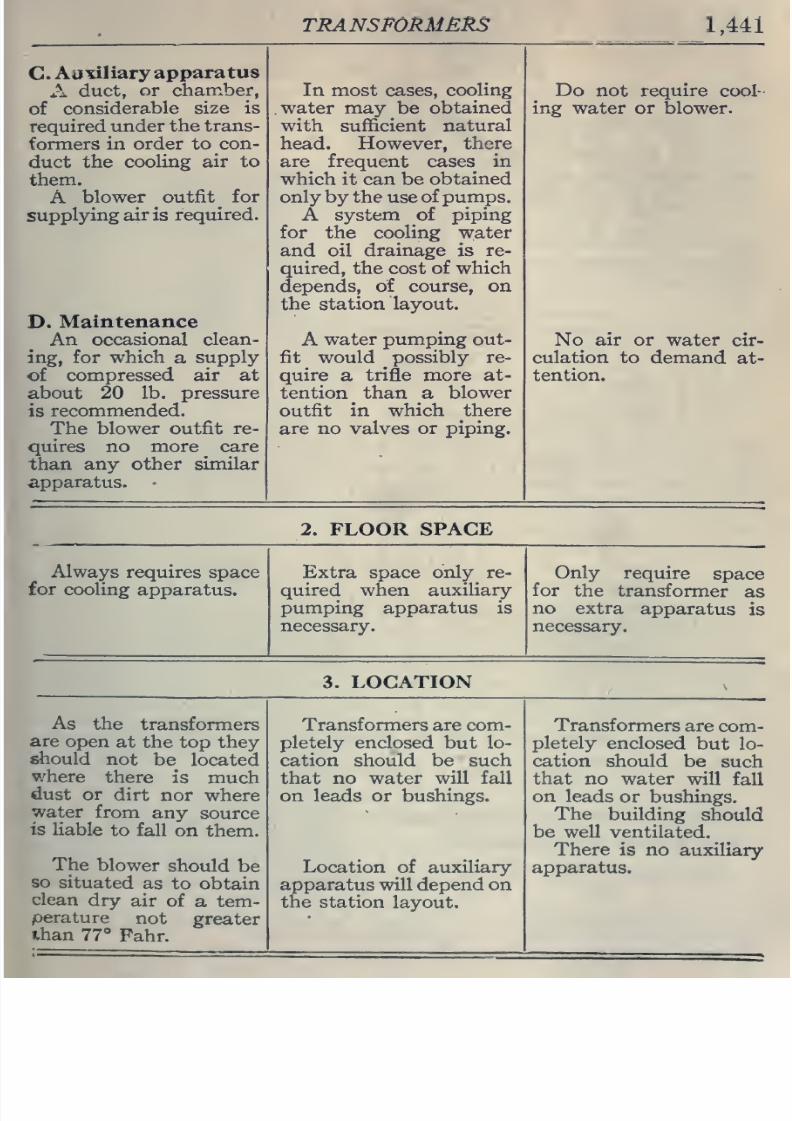
8/20/2019 electrical guide 5.pdf
http://slidepdf.com/reader/full/electrical-guide-5pdf 187/343
TRANSFORMERS
1,441
C.
Auxiliary
apparatus
A
duct,
or chamber,
of
considerable
size
is
required
under
the
trans-
formers in
order
to
con-
duct
the
cooling
air to
them.
A
blower
outfit for
supplying
air
is
required.
D.
Maintenance
An
occasional
clean-
ing, for which
a
supply
of
compressed
air at
about
20
lb.
pressure
is
recommended.
The
blower
outfit
re-
quires
no
more
care
than
any other
similar
apparatus.
In most
cases,
cooling
water may
be
obtained
with
sufficient
natural
head. However,
there
are
frequent
cases in
which it can be
obtained
only
by
the
use
of
pumps.
A system
of
piping
for
the
cooling
water
and
oil
drainage
is
re-
quired, the cost
of which
depends,
of
course,
on
the
station
layout.
A
water
pumping
out-
fit
would possibly
re-
quire
a
trifle more
at-
tention than
a
blower
outfit in which there
are no valves or
piping.
Do
not
require
cool-
ing
water
or
blower.
No
air
or
water
cir-
culation
to demand
at-
tention.
2.
FLOOR
SPACE
Always
requires
space
for
cooling apparatus.
Extra space
only
re-
quired
when
auxiliary-
pumping
apparatus is
necessary.
Only
require
space
for
the
transformer
as
no
extra
apparatus
is
necessary.
3.
LOCATION
As
the
transformers
are
open
at
the
top
they
should
not
be
located
where
there
is much
dust
or
dirt
nor
where
water
from
any
source
is
liable
to
fall
on
them.
The
blower
should
be
so
situated
as to
obtain
clean
dry
air
of
a
tem-
perature
not
greater
than
77
Fahr.
Transformers are
com-
pletely
enclosed
but
lo-
cation should
be
such
that
no water
will
fall
on leads
or
bushings.
Location
of
auxiliary
apparatus
will depend
on
the station
layout.
Transformers
are
com-
pletely
enclosed
but lo-
cation
should
be
such
that
no
water
will
fall
on leads
or
bushings.
The
building
should
be
well ventilated.
There
is
no
auxiliary
apparatus.
8/20/2019 electrical guide 5.pdf
http://slidepdf.com/reader/full/electrical-guide-5pdf 188/343
1,4415
hawkin:>
e ectr c ty
4. GENERAL
APPEARANCE
Terminal
leads may-
be
located
in
the
base
and
the
air chamber
may
be
used
for
con-
ducting
and
distributing
the
connecting
wiring.
The
absence of over-
head wiring aids
in
sim-
plifying
the
appearance
of
the
station.
Leads are
brought out
of
the
top
of
the
trans-
formers.
Water
cooling
pipes
are
connected
at
the
top
in
most
cases.
Leads are
brought out
of
the top of the
trans-
formers.
5.
OPERATION
Equal
reliability
in all
three
types.
While
full load
efficiencies
are
practically
equal in the
three designs, it
is
necessary
to
change
the
proportion
of
iron
and
copper
losses
somewhat
as
the
copper
loss
of
the air
blast
transformer
is a
smaller part
of
its total loss
than
of
the
water
cooled
and
oil
cooled types.
As a
result,
the
regulation
of
the air
blast
transformer is a
trifle
better.
6.
GENERAL
The above
information
regarding selection
of
type is not
applicable
to
air
blast
transformers
for circuits
materially
in excess
of
33,000
volts.
On
account
of
the
great
thickness
of the
solid insulation needed and
the
consequent
difficulty in
radiating heat from the
copper,
it
is impracticable
to
design the
air blast
type for more than
this
voltage.
The
oil
immersed
designs
are therefore
recommended
for
transformers
above
33,000
volts.
Both oil cooled
and
water
cooled
types
are available for
all
voltages,
being
restricted
in this respect
only by
tne
limitations
of
transmission facilities.
Ones.
How
are
transformers
connected
for
four
wire
three
phase
distribution?
Ans.
When
the
secondaries of
three
transformers
are star
NOTE.
—No
special
foundations
are necessary
for any type
of
transformer
other
than
a
good even floor, having sufficient
strength
to
support
the weight-
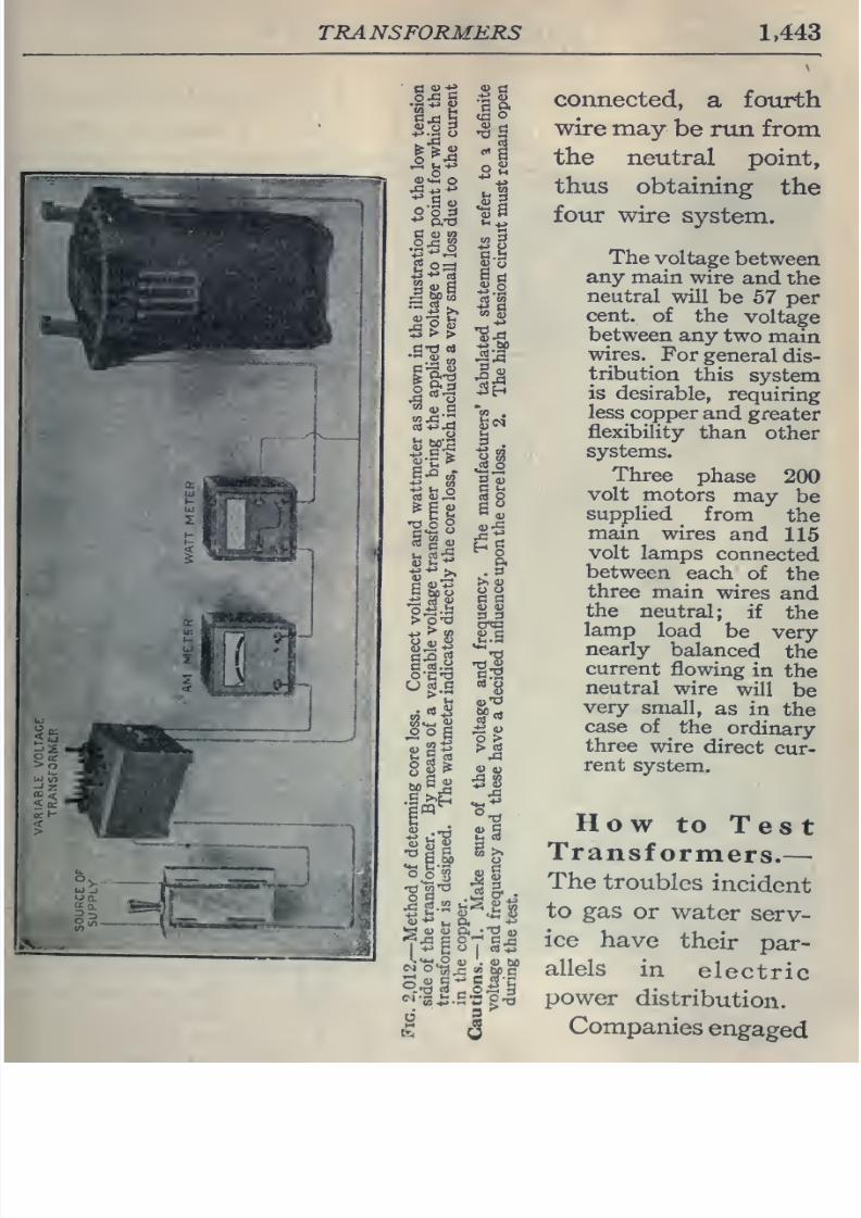
8/20/2019 electrical guide 5.pdf
http://slidepdf.com/reader/full/electrical-guide-5pdf 189/343
TRANSFORMERS
1,443
&,.
.las
H
O
o 3
C
CJ
OT
3
(u
a
o
o
-2s
-(J
^
«
MO
>
CO
c
rt.y
^
O
g
0)
c
•
c
C.t
1^
rt
ss
.
3
>. 0)
u
o
c
a
a>
<u
S 3
•d
•CI
*J
o >
^
(U
(U
ft
•TJ
4,
connected,
a
fourth
wire may
be
run
from
the
neutral
point,
thus
obtaining
the
four wire
system.
The
voltage
between
any
main
wire
and
the
neutral
will
be
57 per
cent,
of
the
voltage
between
any
two
main
wires.
^
For
general
dis-
tribution
this
system
is
desirable,
requiring
less
copper
and
greater
flexibility
than
other
systems.
Three
phase
200
volt
motors
may
be
supplied
from
the
main
wires
and
115
volt
lamps
connected
between
each
of
the
three
main
wires
and
the
neutral;
if
the
lamp
load
be
very
nearly
balanced
the
current
flowing
in
the
neutral
wire
will
be
very
small,
as
in
the
case of
the
ordinary
three
wire
direct
cur-
rent
system.
How
to
Test
Transformers.
—
The
troubles
incident
to
gas
or
water
serv-
ice
have
their
par-
allels
in
electric
power
distribution.
Companies
engaged
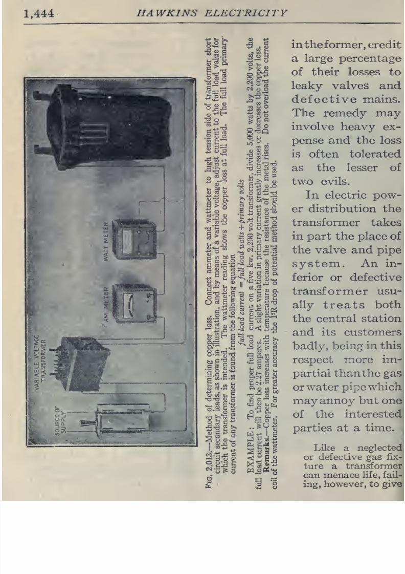
8/20/2019 electrical guide 5.pdf
http://slidepdf.com/reader/full/electrical-guide-5pdf 190/343
1,444
HAWKINS
ELECTRICITY
intheformer,
credit
a
large
percentage
of
their
losses
to
leaky
valves
and
defective
mains.
The
remedy
may
involve heavy
ex-
pense and the
loss
is often tolerated
as
the
lesser of
two
evils.
In electric
pow-
er
distribution the
transformer
takes
in part the
place
of
the
valve
and
pipe
system.
An
in-
ferior or
defective
transformer
usu-
ally
treats
both
the central station
and
its
customers
badly,
being
in
this
respect
more
im-
partial
than
the gas
or
water
pipewhich
may
annoy
but
one
of
the
interested
parties
at a
time.
Like
a
neglected
or defective
gas
fix-
ture
a
transformer
can
menace
life, fail-
ing,
however, to
give
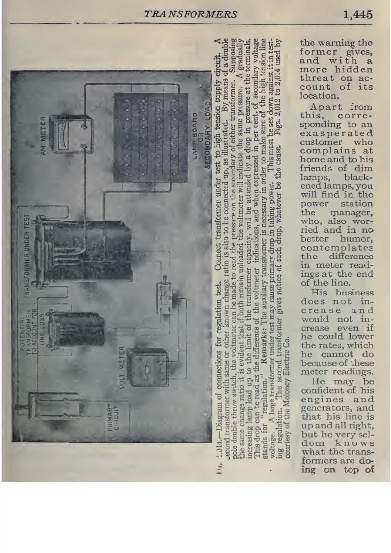
8/20/2019 electrical guide 5.pdf
http://slidepdf.com/reader/full/electrical-guide-5pdf 191/343
TRANSFORMERS
1,445
<Ji
5P
>•
03
S>
2
4L
>»
.e^ Q.-r) S
'-'
^
&d E b
^
«^
S
°
2^1
^
i
a
^
^S?
meet)
>t«r.«^
,
43
o
0.-5
>;.2
n
a-S
S
o
rt^
y- CO jH
w
w'ti'-'wi-ii-iniCo
BbS^I
1
CO
V-
p
S-;^
a
§
S
o
3
rtS
MQ.O
-^
°
^
C W
<U
05^
>
In
m^
o
35
>,
C-S g
+f
^„g
the
warning
the
former
gives,
and
with
a
more
hidden
threat on
ac-
count
of
its
location.
Apart from
this, corre-
sponding
to
an
exasperated
customer who
complains
at
home
and
to his
friends
of
dim
lamps,
black-
ened
lamps,
you
will
find
in the
power station
the
ijianager,
who, also
wor-
ried and
in
no
better
humor,
contemplates
the
difference
in
meter
read-
ings
at
the end
of
the
line.
His business
does
not in-
crease
and
would
not in-
crease even
if
he
could
lower
the rates, which
he
cannot do
because
of these
meter
readings.
He may be
confident
of
his
engines and
generators,
and
that
his
line
is
up
and
all
right,
but
he
very
sel-
dom
knows
what
the trans-
formers
are
do-
ing
on
top
o£
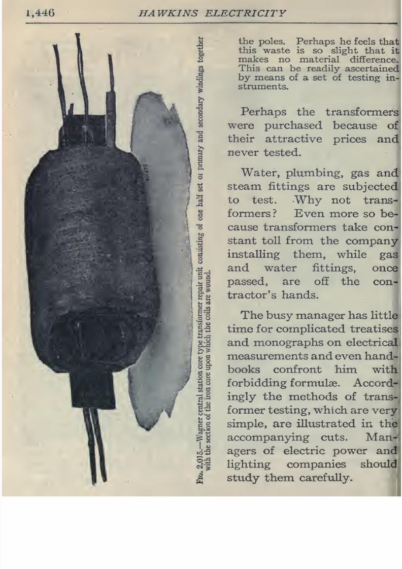
8/20/2019 electrical guide 5.pdf
http://slidepdf.com/reader/full/electrical-guide-5pdf 192/343
1,446
HAWKINS
ELECTRICITY
the poles.
Perhaps
he
feels
that
this
waste is so
slight
that
it
makes
no material
difference.
This
can
be
readily
ascertained
by means
of
a
set of testing
in-
struments.
Perhaps
the
transformers
were purchased
because
of
their
attractive
prices
and
never
tested.
Water, plumbing,
gas
and
steam
fittings
are
subjected
to
test. Why
not
trans-
formers?
Even
more so be-
cause transformers
take
con-
stant toll
from
the
company
installing
them,
while
gas
and
water
fittings,
once
passed, are off
the
con-j
tractor's
hands.
I
The
busy
manager has
little
,
time for complicated
treatises
and
monographs
on
electrical
measurements and even hand-
books confront
him
with
forbidding formulas.
Accord-
ingly
the methods
of
trans-
former testing,
which
are
very
simple,
are
illustrated
in
the
accompanying
cuts.
Man-
agers of
electric
power
and
lighting
companies
should
study
them
carefully.
i
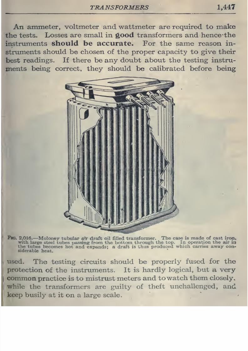
8/20/2019 electrical guide 5.pdf
http://slidepdf.com/reader/full/electrical-guide-5pdf 193/343
TRANSFORMERS
1,447
An
ammeter,
voltmeter
and
wattmeter
are
required to
make
the
tests.
Losses
are
small
in
good
transformers
and
hence the
instruments
should be accurate.
For
the same reason in-
struments should
be
chosen
of
the
proper
capacity
to
give
their
best
readings.
If
there
be
any doubt
about
the
testing
instru-
ments
being correct,
they should be
calibrated before
being
fto. 2,016.
—Moloney
tubular
aT- draft
oil
filled
transformer.
The case is
made
of cast
iron,
with
large
steel
tubes
passing from
the
bottom through
the
top.
In
operation
the
air
in
the
tubes
becomes
hot
and expands;
a
draft
is
thus
produced
which
carries
away
con-
siderable
heat.
used.
The
testing circuits should be
properly
fused
for
the
protection
of
the
instruments. It
is
hardly
logical,
but
a
very
common
practice
is
to
mistrust meters
and
to
watch
them
closely,
while
the
transformers
are
guilty of
theft
unchallenged,
and
keep
busily
at
it
on
a
large
scale.
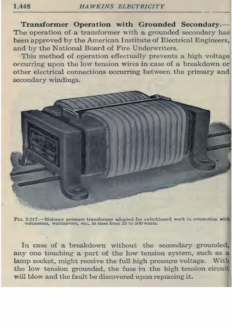
8/20/2019 electrical guide 5.pdf
http://slidepdf.com/reader/full/electrical-guide-5pdf 194/343
1,448
HAWKINS ELECTRICITY
Transformer
Operation
with Grounded Secondary.
—
The
operation
of
a
transformer with
a
grounded secondary
has
been
approved by
the
American
Institute
of Electrical
Engineers,
and
by
the
National
Board
of
Fire
Underwriters.
This
method of
operation
effectually
prevents
a
high
voltage
occurring
upon
the
low
tension
wires
in
case
of
a
breakdown
or
other
electrical
connections occurring
between the
primary
and
secondary
windings.
Fig.
2,017.
—
Moloney pressure transformer
adapted
for
switchboard
work in
connection
rrith
voltmeters,
wattmeters,
etc.,
in
sizes from
25
to
500 watts.
In case of
a
breakdown without the
secondary
grounded,
any
one touching
a
part of
the
low
tension
system,
such
as
a
lamp
socket,
might receive
the
full
high
pressure
voltage.
With
the
low tension
grotinded,
the
fuse in
the
high
tension
circuit
will blow and
the
f
atdt
be
discovered
upon
replacing
it.
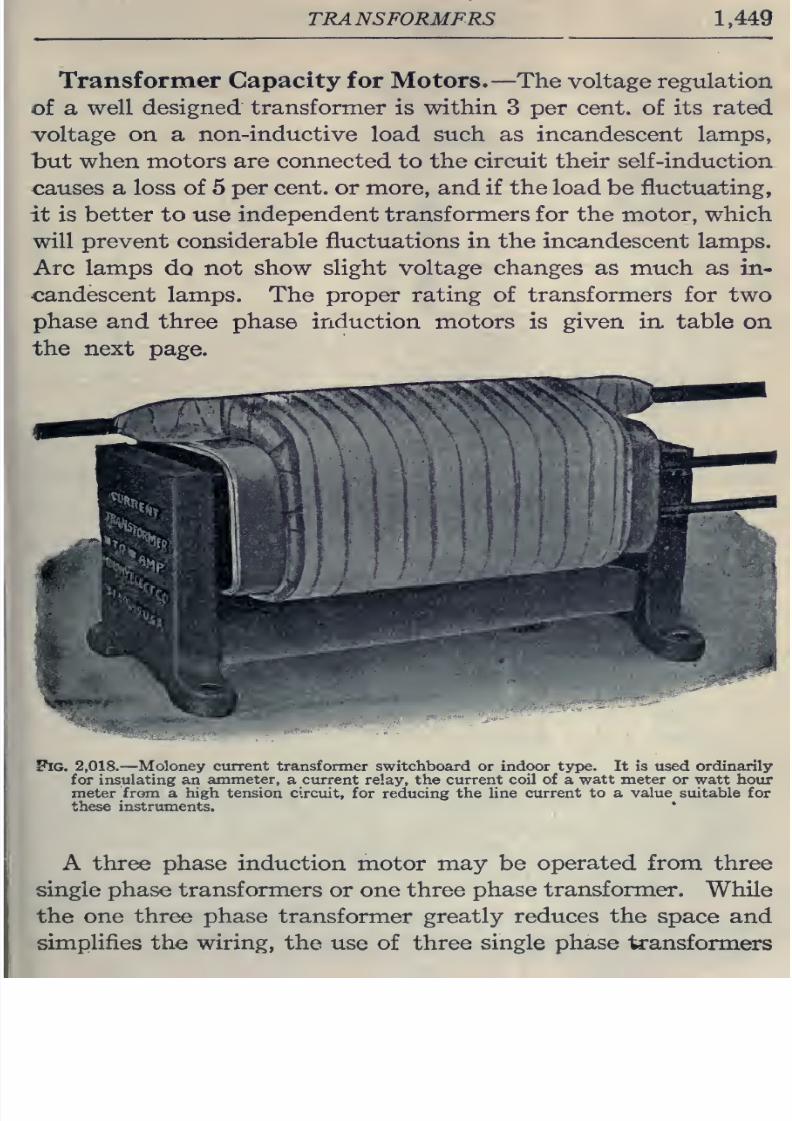
8/20/2019 electrical guide 5.pdf
http://slidepdf.com/reader/full/electrical-guide-5pdf 195/343
TRANS
FORMFRS
1,449
Transformer Capacity
for
Motors.
—The
voltage
regulation
of
a well
designed
transformer
is
within
3 per
cent,
of
its
rated
voltage on
a
non-inductive
load such
as incandescent
lamps,
but
when
motors
are
connected
to
the
circuit
their
self-induction
causes
a
loss
of
5
per
cent,
or
more,
and if
the
load
be fluctuating,
it
is better
to
use independent
transformers
for
the
motor,
which
will prevent considerable fluctuations
in
the
incandescent lamps.
Arc lamps
do
not
show
slight
voltage
changes
as
much
as
in-
candescent lamps. The
proper
rating
of
transformers
for
two
phase and three
phase
induction motors
is
given in
table
on
the
next
page.
Pig.
2,018.
—
Moloney
current
transformer switchboard
or
indoor
type.
It
is used ordinarily
for insulating an
ammeter,
a
current
relay, the
current
coil of a
watt meter
or
watt
hotir
meter
from
a
high
tension
circuit,
for reducing
the
line
current
to
a
value
suitable
for
these
instruments.
A
three phase
induction
motor
may
be
operated
from three
single
phase
transformers
or
one
three
phase
transformer.
While
the
one three
phase
transformer greatly reduces the
space
and
simplifies
the
wiring,
the use
of
three
single phase
fe ansformers
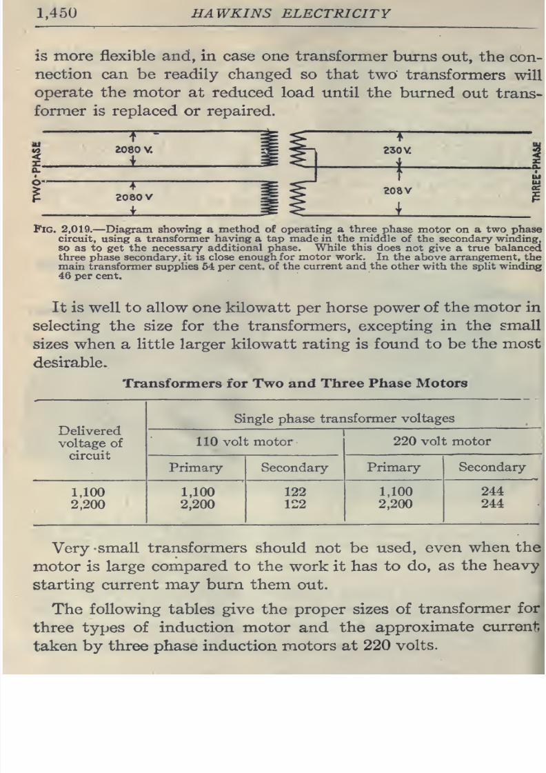
8/20/2019 electrical guide 5.pdf
http://slidepdf.com/reader/full/electrical-guide-5pdf 196/343
1.450
HAWKINS
ELECTRICITY
is
more flexible and,
in
case one
transformer
burns
out,
the
con-
nection
can be readily
changed
so
that
two
transformers
will
operate the
motor at
reduced
load
until
the
burned
out
trans-
former
is
replaced
or
repaired.
2080
V.
230
V
4
2080
V
_i
208
V
1
Fig.
2,019.
—
Diagram showing
a
method
of
operating
a three phase
motor
on
a
two
phase
circuit,
using
a
transformer
having
a
tap
made
in
the
middle
of the
secondary
winding,
so
as
to
get
the
necessary
additional
phase. While this
does
not
give a
true balanced
three
phase
secondary, it
is
close enough
for
motor
work.
In
the
above
arrangement,
the
main
transformer
supplies
54
per cent, of
the
current
and the
other
with
the
split
winding
46
per
cent.
It is
well
to
allow
one kilowatt per horse
power
of
the
motor
in
selecting
the
size
for the
transformers,
excepting in
the
small
sizes when
a
little
larger
kilowatt
rating is
found
to be
the most
desirable.
Transformers
for
Two
and
Three
Phase
Motors
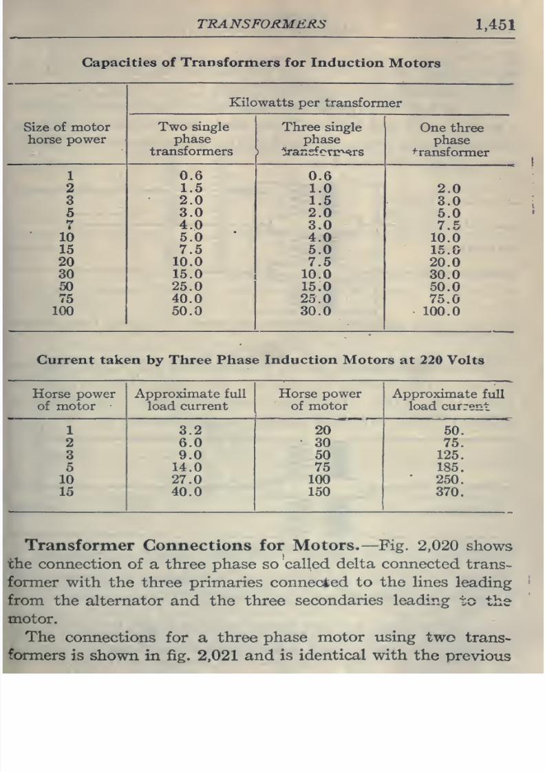
8/20/2019 electrical guide 5.pdf
http://slidepdf.com/reader/full/electrical-guide-5pdf 197/343
TRANSFORMERS
1,451
Capacities
of
Transformers
for
Induction
Motors
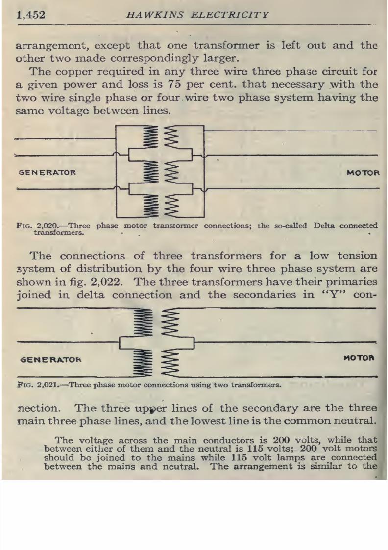
8/20/2019 electrical guide 5.pdf
http://slidepdf.com/reader/full/electrical-guide-5pdf 198/343
1,452
HAWKINS
ELECTRICITY
arrangement, except
that
one
transformer
is
left
out and
the
other
two
made
correspondingly
larger.
The
copper
required
in
any three
wire
three phase circuit for
a
given
power
and
loss
is
75
per
cent,
that
necessary
with
the
tv/o
wire
single
phase
or four.
wire
two
phase system having
the
same
voltage between
lines.
GENERATOR
MOTOR
Fig.
2,020.
—
Three
phase
motor
transtormer
connections;
the so-called
Delta connected
transformers.
The
connections
of
three
transformers
for
a
low
tension
system of
distribution
by
the four
wire
three
phase system
are
shown
in
fig.
2,022.
The three
transformers have
their
primaries
joined
in
delta connection
and
the
secondaries
in
**Y con-
<3ENERAT0H
HOTOh
Pig.
2,021.
—
Three
phase
motor connections using two
transformers.
nection. The three
upj)er
lines
of
the
secondary
are
the
three
main
three
phase
lines,
and
the
lowest
line
is
the
common
neutral.
The voltage across
the
main conductors
is
200
volts,
while that
between
either
of them
and the
neutral
is
115
volts; 200
volt
motors
should be
joined
to the
mains
while 115 volt
lamps
are connected
between
the mains and
neutral.
The
arrangement
is
similar to
the
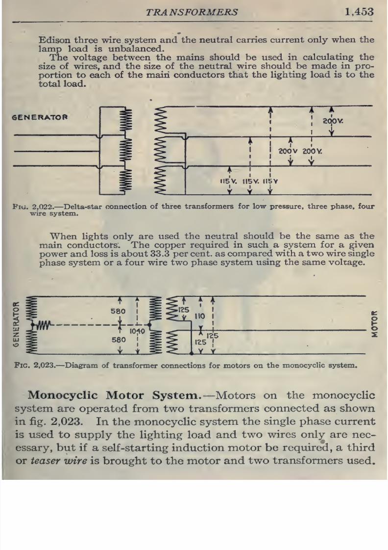
8/20/2019 electrical guide 5.pdf
http://slidepdf.com/reader/full/electrical-guide-5pdf 199/343
TRANSFORMERS
1,453
Edison
three wire
system
and
the
neutral
carries
current
only when
the
lamp load
is
unbalanced.
The
voltage between
the mains
should
be
used
in
calculating
the
size
of
wires, and the size of
the
neutral
wire should
be
made
in
pro-
portion to each of
the
main
conductors
that
the
lighting load
is
to
the
total
load.
GENERATOR
1
—JT
1
sqov
;
I
I
I
200
V
ZOOV.
J
I
t
Y
,
\
I
fl5V.
IIBV.
II5Y
_i
i
i_
Pii;, 2,022.
—
Delta-star
connection
of
three transformers
for
low pressure, three
phase,
four
wire system.
When
lights
only
are
used
the
neutral
should
be
the
same as
the
main
conductors.
The
copper
required in such
a
system
for
a
given
power
and
loss
is
about
33.3
per
cent,
as
compared
with
a two
wire
single
phase
system or
a
four
wire two
phase system
using the
same
voltage.
Fig.
2,023.
—
Diagram of transformer
connections for motors on
the monocyclic system.
Monocyclic
Motor System.
—
Motors on
the monocyclic
system are
operated
from
two
transformers
connected as shown
in
fig.
2,023.
In
the
monocyclic
system
the
single
phase
current
is
used
to supply
the lighting load
and
two
wires only are
nec-
essary,
but if
a self-starting induction
motor
be
required, a
third
or
teaser
wire is
brought
to
the
motor
and
two
transformers
used.
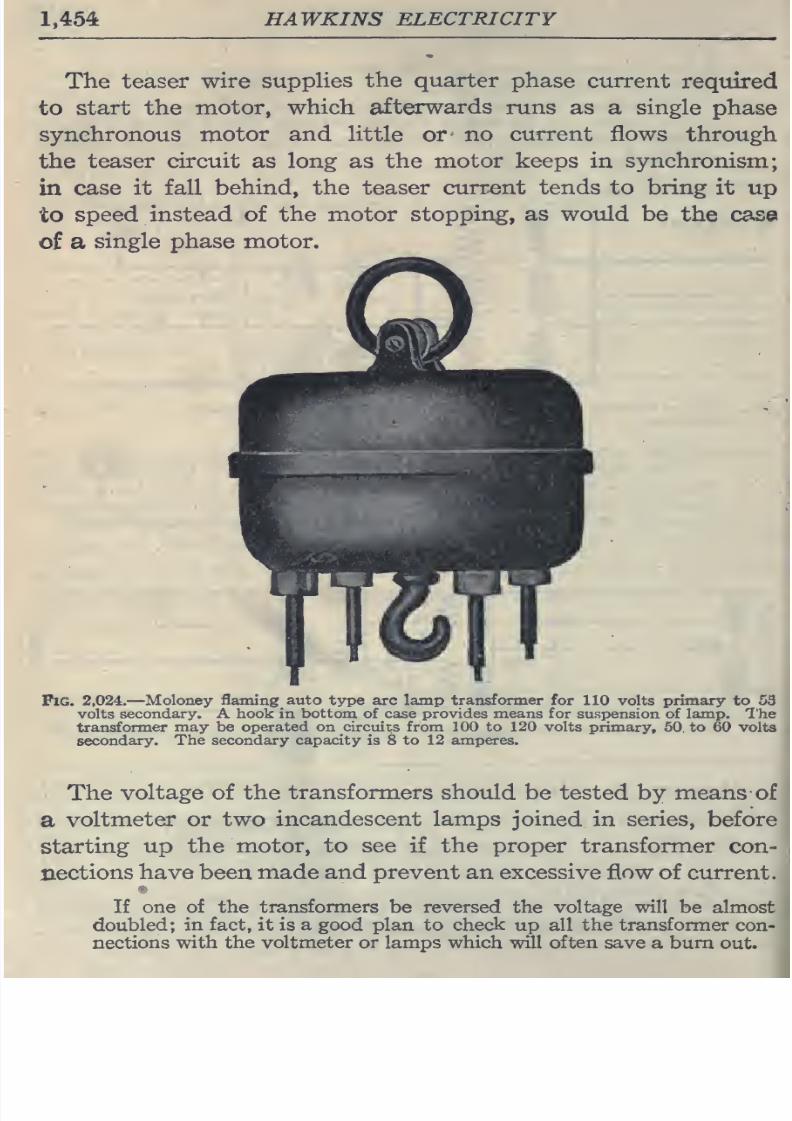
8/20/2019 electrical guide 5.pdf
http://slidepdf.com/reader/full/electrical-guide-5pdf 200/343
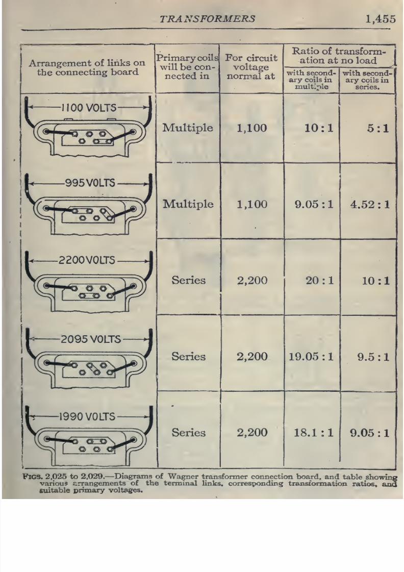
8/20/2019 electrical guide 5.pdf
http://slidepdf.com/reader/full/electrical-guide-5pdf 201/343
TRANSFORMERS
1,455
Arrangement
of
links
on
the
connecting
board
Primary
coils
will
be
con
nected in
For
circuit
voltage
normal
at
Ratio
of
transform-
ation
at
no
load
with
second-
ary
coils
in
multiple
with
second-
ary
coils
in
series.
Multiple
Multiple
Series
Series
Series
1,100
10:1
5:1
1,100
9.05
:
4.52 :
2,200
20:1
10:1
2,200
19.05
:
9.5:1
2,200
18.1:1
9.05
:
Figs.
2,025
to
2,029.
—
Diagrams
of
Wagner
transformer connection board,
and
table
showing
various
arrangements
of the
terminal
links, corresponding
transformation
ratios,
Hng
sxiitable
primary
voltages.
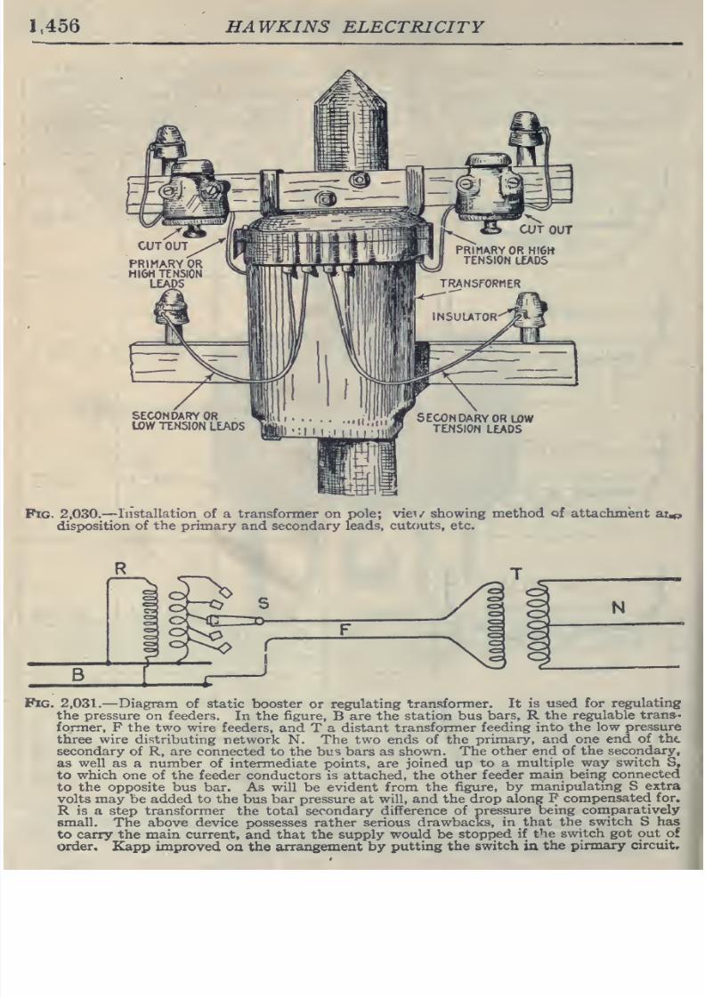
8/20/2019 electrical guide 5.pdf
http://slidepdf.com/reader/full/electrical-guide-5pdf 202/343
1,456
HAWKINS
ELECTRICITY
SECONDARY
OR
LOW
TENSION
LEADS
Pig.
2,030.—
Installation
of a
transformer
on
pole;
viev
showing
method
of
attachment
ai^
disposition
of
the
primary
and secondary
leads,
cutouts,
etc.
Pig. 2,031.
—Diagram of static
booster or
regulating
transformer. It
is used
for
regulating
the pressure
on
feeders.
In
the
figure,
B
are the
station bus
bars,
R
the regulable
trans-
former,
F the
two wire feeders, and
T a
distant transformer
feeding
into
the
low
pressure
three
wire distributing
network
N.
The
two
ends of
the
primary,
and
one
end
of
the.
secondary
of
R, are
connected
to the bus
bars as
shown. The
other
end
of the
secondary,
as
well
as
a
number
of
intermediate
points,
are joined
up
to
a
multiple
way
switch
S,
to
which
one of the
feeder
conductors is attached,
the
other
feeder main
being
connected
to
the
opposite bus
bar.
As
will
be
evident
from
the
figure,
by
m.anipulating
S
extra
volts
may be added to
the
bus
bar
pressure
at
will,
and
the
drop
along
F
compensated for.
R
is
a
step
transformer
the total secondary
difference of
pressure
being
comparatively
small.
The above device
possesses rather
serious
drawbacks,
in
that the
switch
S
has
to carry
the
main
current,
and
that
the
supply would
be
stopped
if
the switch got out of
order,
Kapp
improved
oa the
arrangement
by
putting
the
switch
in
the
pirmary
circuit.
8/20/2019 electrical guide 5.pdf
http://slidepdf.com/reader/full/electrical-guide-5pdf 203/343
CONVERTERS
1,457
CHAPTER
LIII
CONVERTERS
The
alternating
current
must
change
to a direct
current
in
many
cases
as
in
railroad
work
because
the
induction
motor
is
not so
satisfactory
as
the direct current
series motor
and
the
alternating
current
series
motor
is
slow
in
coming
into
general use.
In
all
kinds
of
electrolytic
work,
transformation
must
be
made>
and
in
many cities where the
direct
current
system
was
started,
it
is
still
continued
for
local
distribution,
but the
large
main
stations
generating
alternating currents
and
frequently
located
some
distance
away from the
center
of
distribution
have
replaced
a number
of
small central
stations.
Transformation
may
be
made
by
any of
the
following
methods
1.
Rotary
converters;
2.
Motor
generator
sets
8.
*
Mercury
vapor
rectifiers;
4. *Electrolytic
rectifiers.
Strictly
speaking,
a
converter -is
a
revolving apparatus
for
con-
verting
alternating
current
into
direct
current
or
vice
versa;
it is
usually called
a
rotary
converter
and
is to
be
distinguished
from
the
other methods
mentioned above.
Broadly,
however,
a
converter
may
be
considered
as
any
species
of
apparatus
for
changing
electrical energy
from
one
form^
into
another.
'NOTE.
—Rectifiers are
explained
in
detail
in
Chapter LIV.
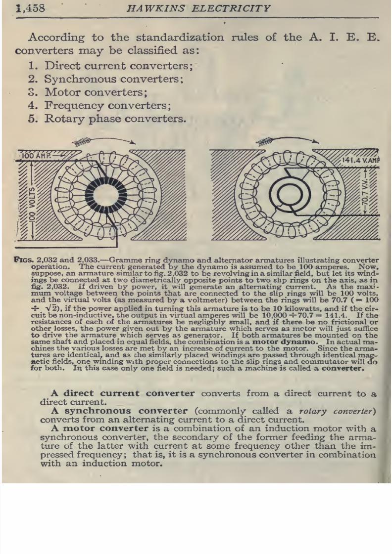
8/20/2019 electrical guide 5.pdf
http://slidepdf.com/reader/full/electrical-guide-5pdf 204/343
.458
HAWKINS
ELECTRICITY
According
to
the
standardization
niles
of
the
A.
I. E.
converters
may
be
classified as:
1. Direct
current
converters;
2.
Synchronous
converters
S.
Motor
converters;
4. Frequency converters
5. Rotary
phase converters.
Pigs. 2,032
and
2,033.
—
Gramme
ring dynamo
and
alternator
armatures illustrating converter
operation. The
current generated
by
the dynamo
is assumed
to
be
100
amperes.
Now,
suppose,
an armature similar
to
fig.
2,032
to be revolving
in
a similar field, but let its
wind-
ings
be connected at
two
diametrically
opposite points
to
two slip
rings
on the
axis,
as
in
fig.
2,032.
If
driven
by
power,
it
will
generate an
alternating
current.
As
the
maxi-
mum
voltage
between the
points that are
connected
to the
slip
rings
will
be
100 volts,
and
the
virtual
volts (as
measured
by
a
voltmeter) between
the
rings will
be
70.7
(
=
100
-7-
V2),
if
the power
applied
in turning this armature
is to
be
10
kilowatts,
and
if
the
cir-
cuit
be
non-inductive,
the
output in
virtual
amperes
will
be
10,000-7-70.7
=
141.4.
If
the
resistances
of each
of the
armatures
be
negligibly small,
and if
there be
no
frictional
or
other
losses, the power
given
out
by
the armature which serves
as
motor will just suffice
to
drive
the
armature
which
serves
as
generator.
If
both
armatures
be
mounted
on
the
same
shaft
and
placed
in equal fields, the combination is
a
motor dynamo.
In actual
ma-
chines
the
various
losses
are
met by an increase of
current
to the motor. Since
the arma-
tures
are identical, and
as
che
similarly
placed
windings
are
passed
through
identical
mag-
netic
fields,
one winding
with proper connections
to the
slip rings
and
commutator
will
do
for
both.
In
this
case only
one field is
needed;
such
a
machine
is called
a
converter.
A
direct current converter
converts
from
a
direct
current
to
a
direct
current.
A
synchronous
converter (commonly
called
a
rotary
converter)
converts
from
an
alternating
current
to
a
direct current.
A
motor
converter
is
a
combination
of an
induction
motor
with
a
synchronous converter,
the
secondary
of
the
former
feeding
the
arma-
ture
of
the latter
with current
at some frequency other
than the
im-
pressed
frequency; that
is,
it is
a
synchronous converter
in
combination
with
an
induction
motor.
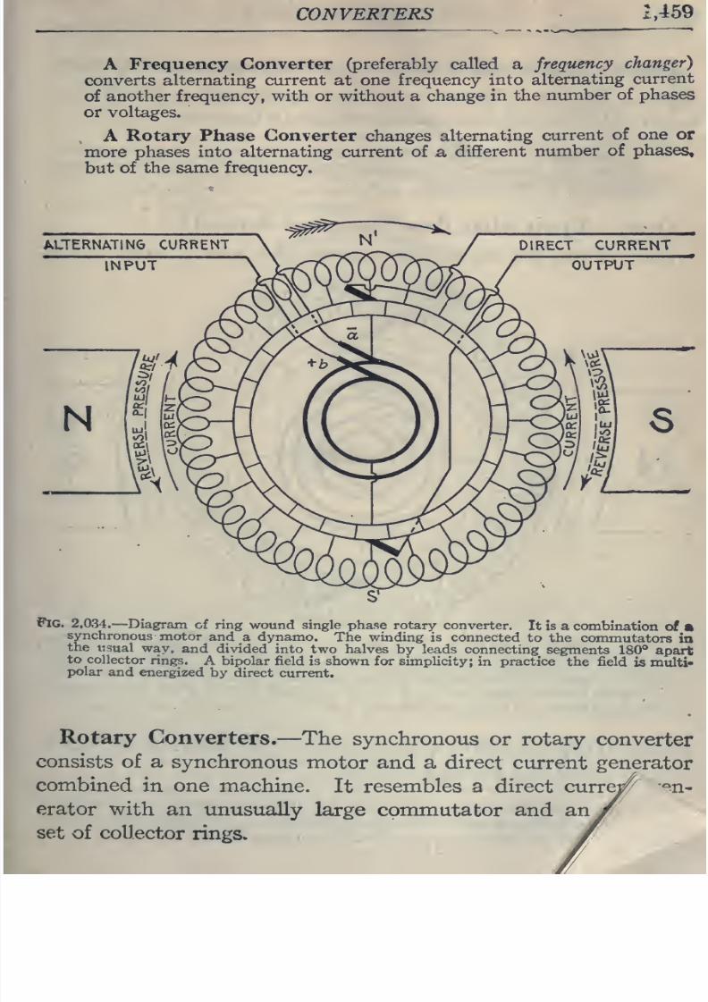
8/20/2019 electrical guide 5.pdf
http://slidepdf.com/reader/full/electrical-guide-5pdf 205/343
CONVERTERS
2,459
A
Frequency
Converter
(preferably
called
a
frequency
changer)
converts
alternating
current
at
one frequency
into
alternating
current
of
another
frequency, with
or
without a
change
in the
number
of phases
or
voltages.
A
Rotary Phase
Converter
changes
alternating
current
of
one
or
more
phases
into alternating
current
of
a,
different
number
of
phases,
but
of
the
same frequency.
Pig.
2.034.
—
Diagram
of
ring
wound
single
phase
rotary converter.
It is
a
combination
of
•
synchronous
motor
and
a
dynamo.
The
winding
is
connected
to
the
commutators
in
the
usual
way,
and divided
into
two halves
by leads connecting
segments
180°
apart
to
collector
rings.
A bipolar field
is
shown
for
simplicity;
in
practice
the
field
is multi*
polar
and
energized
by
direct
current.
Rotary
Converters.
—The
synchronous
or
rotary converter
consists
of
a
synchronous
motor
and
a
direct
current
generator
combined
in
one machine.
It
resembles a
direct
curre^
'^n*
erator
with
an
unusually
large commutator and
an
set
of collector
rings.
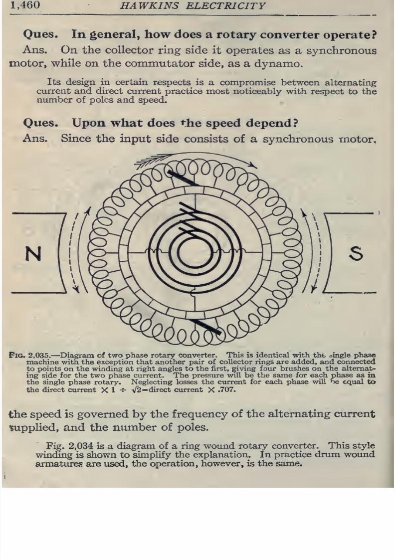
8/20/2019 electrical guide 5.pdf
http://slidepdf.com/reader/full/electrical-guide-5pdf 206/343
1,460
HAWKINS
ELECTRICITY
Oues.
In
general,
how
does
a rotary
converter
operate?
Ans.
On
the
collector ring
side
it
operates
as
a
synchronous
motor,
while
on the
commutator
side,
as
a
dynamo.
Its
design
in
certain
respects
is
a
compromise
between
alternating
current
and direct
current practice most
noticeably with respect
to
the
number
of
poles
and
speed.
Ques.
Upon what does
the speed depend?
Ans.
Since
the
input
side
consists of a
synchronous
motor,
Pig.
2,035.—Diagram of
two
phase
rotary
converter.
This
is
identical
with
the
single
phase
machine
with the
exception
that another pair
of
collector rings are added, and connected
to
points
on the
winding at right angles to
the first, giving
four
brushes
on
the
alternat-
ing
side for
the
two
phase ctirrent.
The
pressure will be
the
same
for each phase
as
in
the single
phase
rotary.
Neglecting losses
the
current for
each
phase
will
be
equal
to
the
direct current
X
1
-^
V2=
direct current
X
.707.
the speed
is governed
by
the
frequency
of the
alternating
ctirrent
•supplied,
and
the
number
of
poles.
Fig.
2,034
is
a
diagram of
a
ring wound rotary
converter.
This style
winding
is
shown
to
simplify
the
explanation. In
practice
drum wound
armatures are
used,
the
operation,
however,
is
the same.
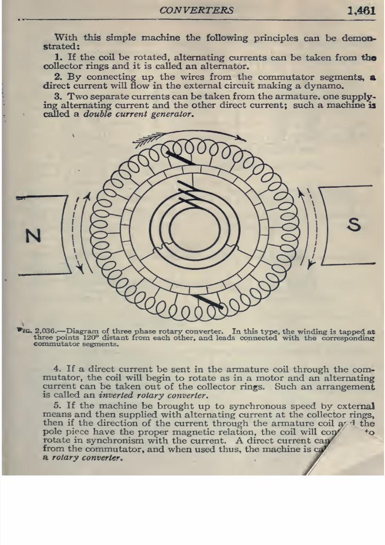
8/20/2019 electrical guide 5.pdf
http://slidepdf.com/reader/full/electrical-guide-5pdf 207/343
CONVERTERS
1,461
With this
simple
machine
the
following
principles
can be demon-
strated:
1.
If
the
coil be
rotated,
alternating
currents can
be
taken
from
tho
collector rings
and it is
called
an
alternator.
2.
By
connecting
up
the
wires
from
the
commutator
segments,
a
direct
current will
flow
in
the
external circuit making
a
dynamo.
3. Two
separate currents can
be
taken from the armature, one
suppl]^-
Ing
alternating current
and
the other
direct current;
such
a
machme
is
caSed
a
double
current generator.
•JG.
2,036.
—
^Diagram
of
three
phase
rotary
converter.
In
this
type,
the
winding
is
tapped
at
three
points
120°
distant
from
each
other,
and
leads connected
with the corresponding
commutator
segments.
4.
If
a
direct
current
be
sent in
the armature
coil
through the
com-
mutator,
the
coil will
begin
to rotate
as
in
a
motor
and an alternating
current
can
be
taken
out
of
the collector
rings.
Such
an arrangement
is called
an inverted
rotary
converter.
5. If the
machine
be
brought
up to
synchronous
speed by external
means
and
then
supplied
with
alternating
current at the
collector
rings,
then
if the
direction
of the current through the
armature
coil
a;
-1
the
pole
piece
have
the
proper magnetic relation,
the coil will
cop^
^o
rotate
in
synchronism
with
the
current.
A
direct current
ca^
from
the
commutator,
and
when
used
thus,
the
machine is
a
rotary
converter.
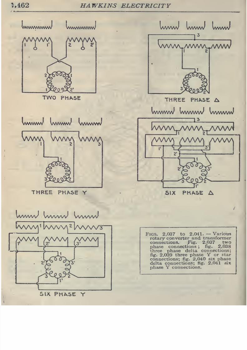
8/20/2019 electrical guide 5.pdf
http://slidepdf.com/reader/full/electrical-guide-5pdf 208/343
^,462
HAWKINS
ELECTRICITY
WWWA/VWW
WAAWWWW
MAMM
TWO
PHASE
VWWVVW
Vl^fimH
\^N\N\htH
VWW\
VWW\
VWW\
THREE
PHASE
Y
WvMAA/
VWWW
VWVwJ
tvWM^ |aAA^\A^
|aaA/V3
—
WWWV
WWVW
VWWW
\/WVAJWA/V\^JV\AA/J
THREE
PHASE
A
vwwww
wwwwv
vwwwJ
lAAAAA^TVWVNupAAAA/J
|AMA/^
(AAAA^
AAAAA
SIX
PHASE
A
Figs. 2.037
to
2,041.
—
Various
rotary
converter
and
transformer
connections.
Fig. 2,037
two
phase
connections
;
fig.
2,038
three
phase delta
connections;
fig.
2,039
three
phase
V
or
star
connections;
fig.
2,040
six
phase
delta
connections;
fig. 2,041
six
phasfe
Y
connections.
SIX
PHASE
Y
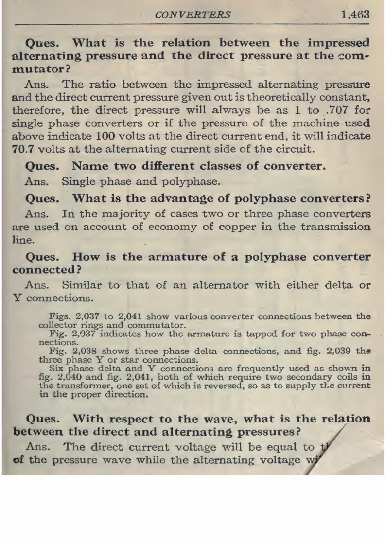
8/20/2019 electrical guide 5.pdf
http://slidepdf.com/reader/full/electrical-guide-5pdf 209/343
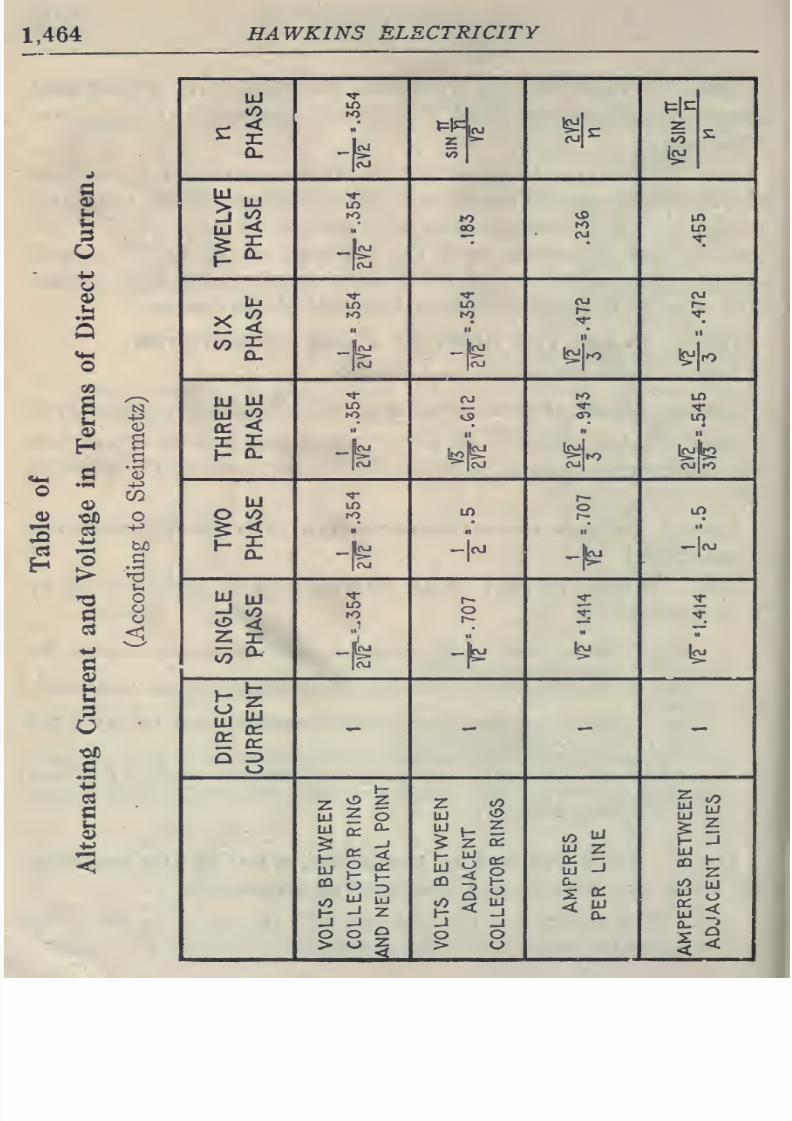
8/20/2019 electrical guide 5.pdf
http://slidepdf.com/reader/full/electrical-guide-5pdf 210/343
HAWKINS
ELECTRICITY
to
o
u
O
o
<
UJ
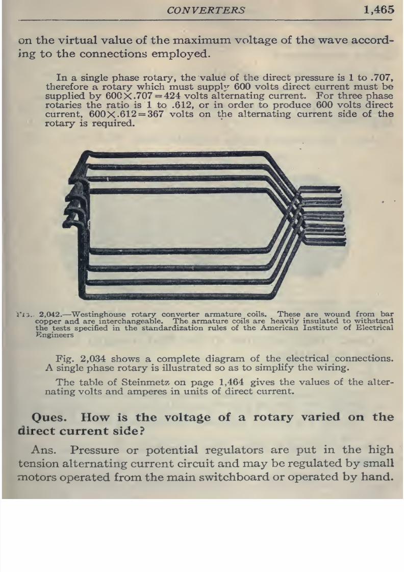
8/20/2019 electrical guide 5.pdf
http://slidepdf.com/reader/full/electrical-guide-5pdf 211/343
CONVERTERS
1,465
on
the
virtual value of
the
maximum
voltage
of the wave
accord-
ing to
the
connections
employed.
In
a
single
phase rotary, the
value
of
the
direct
pressure is 1
to
.707,
therefore
a
rotary
which
must
supply
600
volts
direct
current
must
be
supplied
by
600X.707
=
424
volts
alternating
current.
For three
phase
rotaries the ratio is 1 to
.612,
or
in order
to
produce
600
volts
direct
current,
600X.612
=
367
volts
on
the alternating
current
side of
the
rotary is required.
Vis..
2,042.
—
Westinghouse rotary
converter armature
coils. These are
wound from
bar
copper
and are
interchangeable.
The
armature
coils are
heavily
insulated to
withstand
the tests specified in
the
standardization
rules of
the American
Institute of Electrical
Engineers
Fig.
2,034
shows
a
complete
diagram
of
the
electrical connections.
A single
phase rotary is
illustrated so as
to
simplify
the wiring.
The table
of
Steinmetz on
page
1,464
gives
the
values
of
the alter-
nating
volts
and
amperes
in units
of
direct
current.
Oues.
How
is the
voltage
of
a
rotary
varied
on
the
direct
current
side?
Ans.
Pressure
or
potential
regulators
are put
in the high
tension
alternating
current
circuit
and
may be
regulated
by small
motors operated
from
the
main
switchboard
or
operated by
hand.
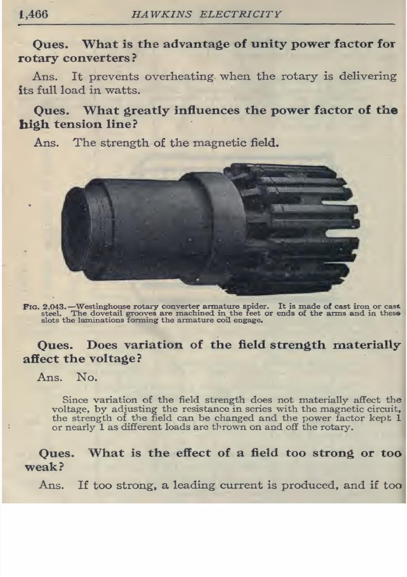
8/20/2019 electrical guide 5.pdf
http://slidepdf.com/reader/full/electrical-guide-5pdf 212/343
1,466
HAWKINS
ELECTRICITY
Oues.
What
is
the advantage
of
unity
power factor for
rotary
converters ?
Ans.
It
prevents
overheating,
when
the
rotary is
dehvering
its
full load
in
watts.
Oues.
What
greatly influences
the
power factor
of
the
high
tension line?
Ans.
The
strength
of
the
magnetic field.
Fig.
2,043.—
Westlnghouse rotary
converter
armature
spider.
It is made
of cast
iron
or
cast
steel. The
dovetail grooves are
machined
in
the feet
or
ends
of
the
arms and in
these
slots
the
laminations
forming
the armature coil
engage.
Oues.
Does
variation
of the
field
strength
materially
affect
the
voltage?
Ans.
No.
Since
variation of
the
field strength does not materially affect
the
voltage,
by
adjusting the resistance in series with
the
magnetic
circuit,
the
strength of
the field can be changed
and
the
power
factor kept 1
or
nearly
1
as
different loads
are
thrown
on and off the rotary.
Oues.
What
is the
effect
of a
field
too
strong
or
too
weak?
Ans.
If
too
strong,
a
leading
current
is
produced,
and if
too
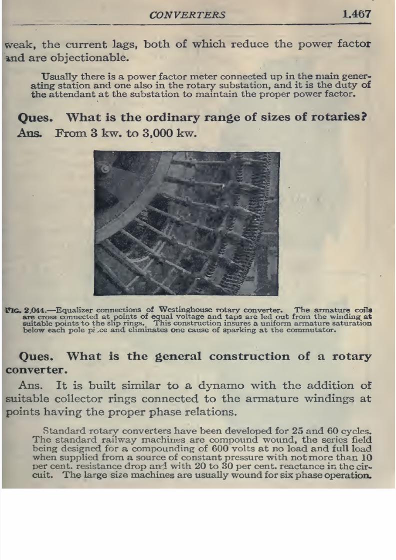
8/20/2019 electrical guide 5.pdf
http://slidepdf.com/reader/full/electrical-guide-5pdf 213/343
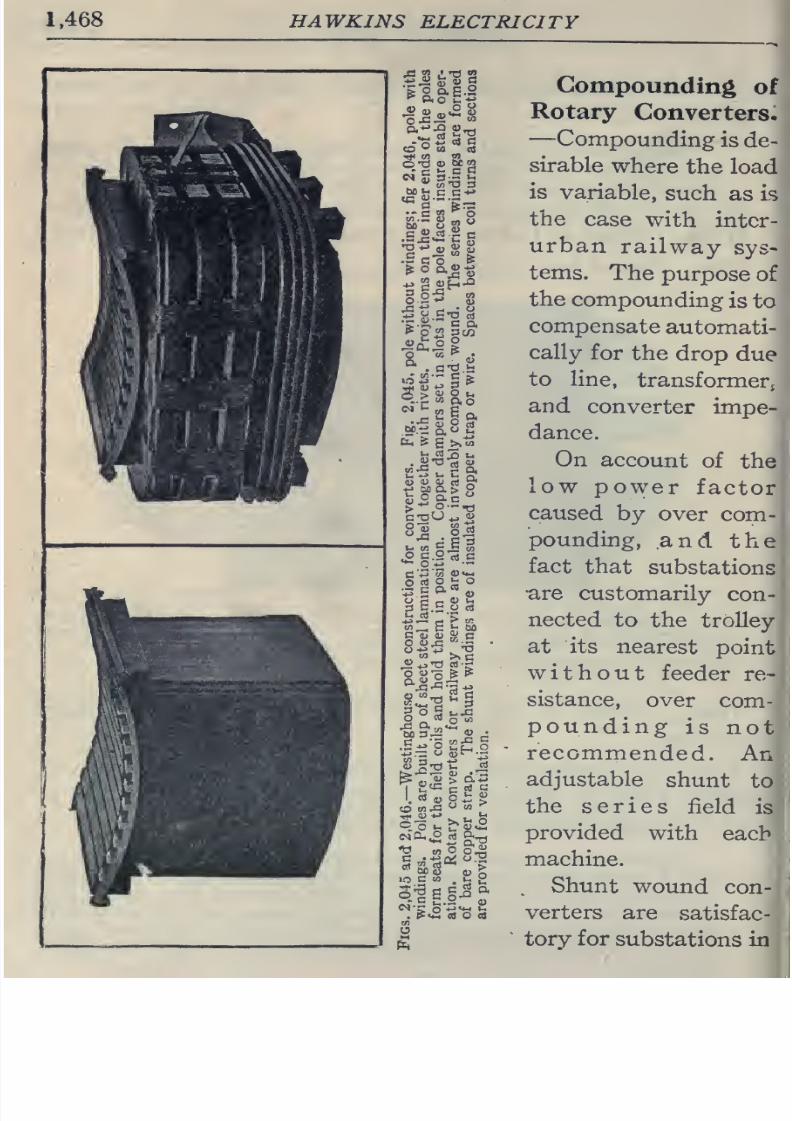
8/20/2019 electrical guide 5.pdf
http://slidepdf.com/reader/full/electrical-guide-5pdf 214/343
1.468
HAWKINS
ELECTRICITY
Compounding
of
Rotary
Converters.
—
Compounding
is
de-
sirable
where
the
load
is
variable,
such
as is
the
case
with
inter-
urban
railway
sys-
tems.
The
purpose
of
the
compoimding
is
to
compensate
automati-
cally
for
the
drop
due
to
line,
transformer,
and
converter
impe-
dance.
On
account
of
the
low
power
factor
caused
by
over
com-
pounding,
and
the
fact
that
substations
•are
customarily
con-
nected
to
the trolley
at
its
nearest
point
without
feeder
re-
sistance,
over
com-
pounding
is
not
recommended.
An
adjustable
shunt
to
the series
field
is
provided
with
each
machine.
Shunt
wound
con-
verters
are
satisfac-
tory
for
substations
in
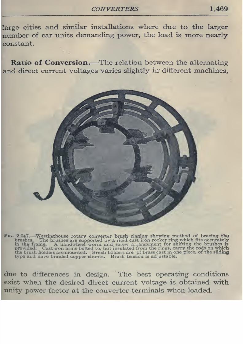
8/20/2019 electrical guide 5.pdf
http://slidepdf.com/reader/full/electrical-guide-5pdf 215/343
CONVERTERS
1,469
cities
and
similar
installations
where
due
to
the larger
of car
units
demanding power, the
load
is more nearly
Ratio of
Conversion.
—The
relation between
the
alternating
direct
current
voltages
varies
slightly
in'
different
machines,
Pig.
2,047.
—
^Westinghouse
rotary converter brush
rigging
showing
method
of
bracing
the
brushes.
The
brushes are
supported
by
a
rigid
cast iron
rocker
ring
which fits accurately
in
the frame.
A
handwheel
worm and
screw
arrangement
for
shifting
the
brushes
is
provided.
Cast
iron arms bolted
to,
but
insulated
from
the
rings,
carry the
rods
on
which
the brush
holders
are
mounted. Brush
holders are of
brass
cast in
one
piece,
of
the
sliding
type
and
have
braided
copper shunts. Brush
tension
is
adjustable.
due
to
differences
in
design. The best
operating conditions
exist
when
the
desired
direct
current
voltage is
obtained
with
unity
power
factor
at the
converter
terminals
when
loaded.
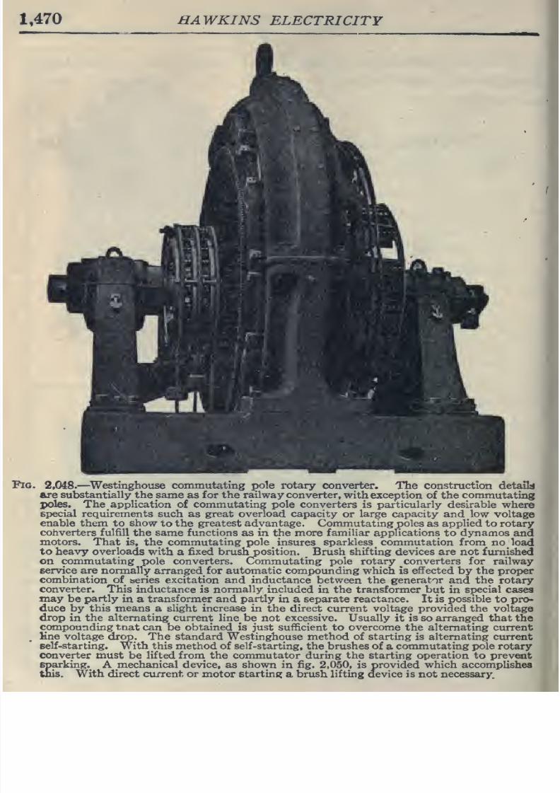
8/20/2019 electrical guide 5.pdf
http://slidepdf.com/reader/full/electrical-guide-5pdf 216/343
1,470
HAWKINS
ELECTRICITY
^di
Fig.
2,048.
—
^Westinghouse
commutating
ipole
rotary
converter.
The
construction
detail:*
axe substantially the same
as
for the
railway
converter,
with exception
of the
commutating
X)oles. The
application
of
commutating pole converters
is
particularly desirable
where
special requirements such
as
great
overload capacity
or
large
capacity and low
voltage
enable them
to
show
to
the
greatest advantage.
Commutating
poles
as
applied
to rotary
converters
fulfill
the
same
functions
as
in
the
more
familiar
applications
to
dynamos
and
motors. That is,
the
commutating
pole
^
insures
sparkless
_
commutation
from
no
load
to
heavy
overloads
with
a
fixed
brush
position.
^
Brush
shifting
devices
are
not
furnished
on
commutating
pole converters. Commutating pole
rotary
converters for
railway
service are normally
arranged
for
automatic
compounding
which
is
effected
by
the proper
combination of series excitation and
inductance
between
the generator and the
rotary
converter.
This inductance
is
normally
included
in
the
transformer but
in
special
cases
may
be
partly
in
a
transformer
and
partly
in a
separate reactance.
It is
possible
to pro-
duce
lay this
means
a
slight increase
in
the
direct current
voltage provided
the
voltage
drop
in
the
alternating current
line be not
excessive.
Usually
it
is so arranged
that
the
compounding
tnat
can be obtained is just sufficient
to
overcome
the
alternating current
,
Kne
voltage drop. The standard Westinghouse
method
of
starting
is
alternating
current
self-star
ting.
With this
method
of
self-starting,
the
brushes
of
a
commutating
pole rotary
converter must
be lifted
from_
the
commutator during
the starting
operation to prevent
sparking.
A
mechanical device,
as
shown
in fig.
2,050,
is
provided
which
accomplishes
this. With
direct
ciirrent
or
motor starting
a
brush
lifting
device is not necessary.
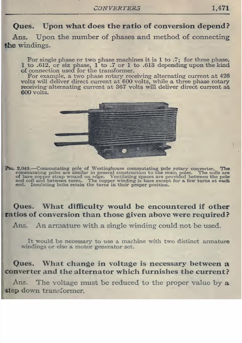
8/20/2019 electrical guide 5.pdf
http://slidepdf.com/reader/full/electrical-guide-5pdf 217/343
CONVERTERS
1,471
Oues.
Upon
what does
the
ratio of conversion
depend?
Ans.
Upon
the
number
of
phases
and
method of
connecting
the
windings.
For
single
phase or
two
phase
machines
it
is
1 to
.7;
for
three
phase,
1
to
.612,
or six
phase,
1
to
.7
or
1
to .613
depending
upon
the
kind
of
connection used
for
the
transformer.
For
example,
a two phase
rotar}?-
receiving alternating current
at
426
volts
will
deliver direct current
at
600 volts,
while
a
three
phase
rotary-
receiving'
alternating current
at 367
volts
will
deliver direct
current
at
600
volts.
Jhtit
2,049.
—
Cojiunutating
pole
of
Westinghouse
commutating
pole
rotary
converter.
The
commutating
poles
are
similar
in
general
construction
to
the
main
poles.
The
coils are
of bare
copper strap
wound on
edge.
Ventilating
spaces are
provided between the
pole
and
coil
and between
turns.
The
copper
winding
is
bare
except for
a
few turns
at
each
end.
Insulating
bolts
retain the
turns
in their
proper position.
Oues.
What
difficulty
would
be encountered
if
other
ratios
of
conversion than
those given above
were
required?
Ans.
An
armature
with a single winding could
not
be
used.
It
would
be
necessary
to
use
a
machine
with two distinct
armature
windings
or
else
a motor
generator
set.
Owes.
What
change
in
voltage is
necessary
between
a
converter
and the
alternator which
furnishes the
current?
Ans.
The
voltage
must
be
reduced
to
the
proper
value
by
a
step
down
transformer.
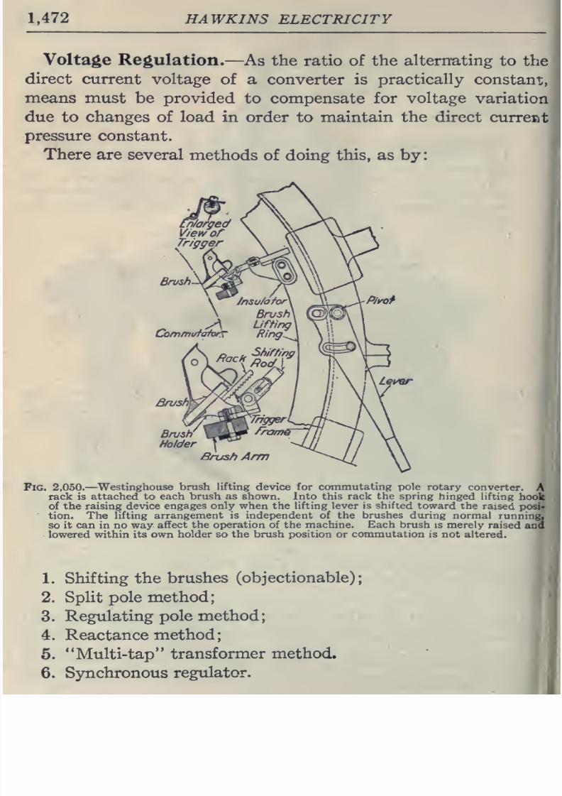
8/20/2019 electrical guide 5.pdf
http://slidepdf.com/reader/full/electrical-guide-5pdf 218/343
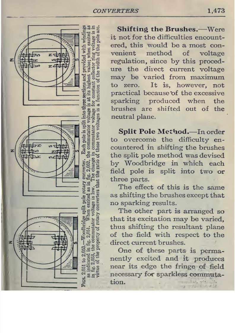
8/20/2019 electrical guide 5.pdf
http://slidepdf.com/reader/full/electrical-guide-5pdf 219/343
CONVERTERS
1,473
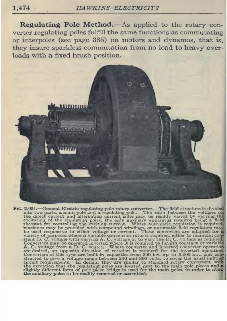
8/20/2019 electrical guide 5.pdf
http://slidepdf.com/reader/full/electrical-guide-5pdf 220/343
1,474
HAWKINS ELECTRICITY
Regulating
Pole
Method.
—
As
applied
to the
rotary con-
verter
regulating
poles
fulfill
the
same functions
as commutating
or
interpoles
(see
page
385)
on
motors
and
dynamos,
that
is,
they
insure sparkless
commutation
from
no
load
to
heavy
over-
loads
with
a
fixed
brush
position.
Fig.
2,054.
—
General
Electric regulating
pole
rotary
converter.
The
field structure is
divided
into
two parts,
a main
pole
and a
regulating pole.
The ratio
between
the
voltages on
the_
direct
current
and
alternating current
sides
may be
readily
varied
h<f
varying the
excitation
of
the
regulating poles,
the only
auxiliary
apparatus
required
being
a
field
rheostat for
controlling
the exciting current. Where
automatic
regulation is
required,
,
machines
may be
provided with compound
windings, or
automatic
field
regulators
may
be
used responsive
to either
voltage
or
current.
These converters
are
adapted
for
a
variety
ofpurposes where
a
variable
conversion
ratio is
required, either to
maintain
C(jn-
stant
D.
C.
voltage
with
varying
A. C.
voltage
or to
vary the
D.
C.
voltage as
required.
Converters
may
be operated
inverted
where
it
is required to_
furnish
constant
or
variable
I
A. C.
voltage
from
a
D.
C.
source.
Where
converter and
inverted
converter
operation
j
are
desired,
an
opposite
direction
of
rotation
is required
for
the
inverted
operation.
Converters of
this
type
are
built
in
capacities
from
300 kw.
up
to 3,000
kw.,
and
con-
structed
to
give
a
voltage
range
between 240 and 300
volts,
to
cover the
usual
lighting
circuit requirements.
In
design,
they
are
similar
to
standard rotary
converters,
witn
the
exception that
the
regulating
poles
are located next to
the
main
pole
pieces
and
a
slightly
different
form
of pole piece
bridge
is used for the
main
poles,
iji
order to aUoW
the
auxiliary poles
to
be
readily removed or
assembled.
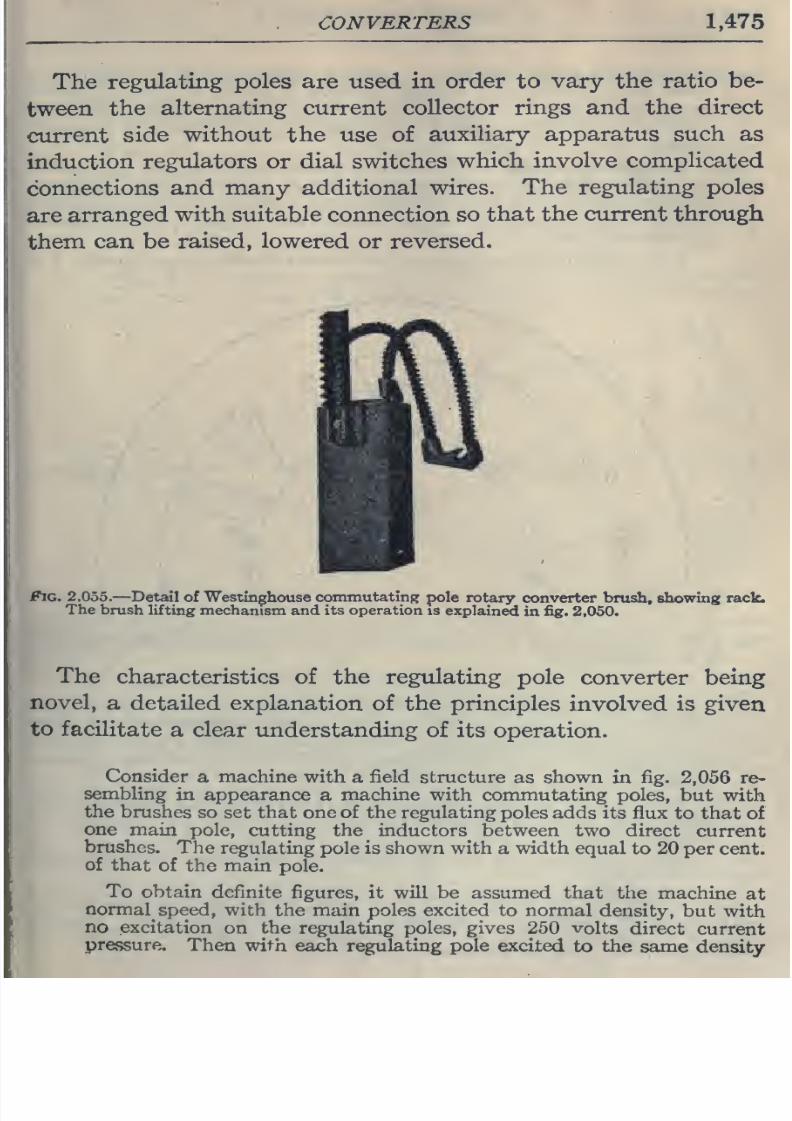
8/20/2019 electrical guide 5.pdf
http://slidepdf.com/reader/full/electrical-guide-5pdf 221/343
CONVERTERS 1,475
The
regulating
poles
are
used
in order
to
vary
the
ratio
be-
tween
the
alternating current
collector rings
and the
direct
current
side
without the
use
of
auxiliary apparatus such as
induction
regulators
or
dial
switches
which
involve
complicated
connections
and many additional
wires.
The
regulating poles
are
arranged
with suitable connection so
that the
current
through
them
can
be
raised,
lowered
or
reversed.
Fig.
2,055.
—Detail of
Westinghouse
commutating
pole
rotary
converter
brush,
showing
rack.
The
brush
lifting
mechanism
and
its
operation
is
explained
in
fig. 2.050.
The
characteristics
of
the
regulating
pole
converter
being
novel,
a
detailed
explanation
of
the
principles
involved is given
to
facilitate
a clear understanding
of
its
operation.
Consider
a
machine
with
a
field
structure
as
shown
in
fig.
2,056
re-
sembling
in
appearance
a
machine
with commutating
poles,
but with
the
brushes
so
set
that one
of
the regulating poles
adds
its flux
to
that of
one
main
pole,
cutting
the_
inductors between
two
direct
current
brushes.
The
regulating pole
is
shown
with
a
width
equal
to
20
per
cent,
of
that
of
the
main
pole.
To
obtain
definite
figures, it will
be
assumed that the
machine
at
normal
speed, with
the
main poles excited
to normal
density,
but
with
no
excitation
on
the
regulatmg
poles,
gives 250
volts
direct
current
pressure.
Then
with
each
regulating pole
excited
to
the
same density
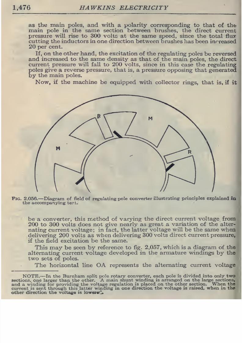
8/20/2019 electrical guide 5.pdf
http://slidepdf.com/reader/full/electrical-guide-5pdf 222/343
1,476
HAWKINS
ELECTRICITY
as
the
main poles, and with
a
polarity
corresponding
to
that
of
the
main pole in the
same
section between
brushes, the
direct
current
pressure
will
rise
to 300 volts
at
the
same
speed,
since
the
total flux
cutting the inductors
in
one
direction
between
brushes
has
been increased
20
per
cent.
If,
on
the other hand,
the
excitation
of the
regulating
poles
be
reversed
and
increased
to
the
same density
as that
of
the
main poles,
the
direct
current pressure will
fall
to
200
volts,
since
in this
case
the
regulating
poles
give
a
reverse pressure, that
is,
a
pressure
opposing that generated
by
the
main
poles.
Now,
if
the machine
be
equipped
with
collector
rings,
that
is,
if
it
Fig.
2,056.
—
Diagram of
field
of
regulating
pole
converter
illustrating
principles
explained
isi
the accompanying
text.
be
a
converter, this
method
of
varying
the direct
current
voltage from
200
to 300
volts
does
not
give nearly as
great
a
variation
of
the alter-
nating
current voltage;
in
fact,
the
latter
voltage will
be the
same
when
delivering 200 volts as
when delivering
300 volts
direct
current
pressure,
if
the
field
excitation
be
the
same.
This may be
seen
by
reference
to fig.
2,057,
which is
a
diagram
of
the
alternating
current
voltage
developed
in the armature windings
by the
two
sets
of
poles.
The
horizontal line OA
represents
the alternating current
voltage
NOTE.
—In the
Burnham
split
pole rotary
converter, each
pole is
divided into
only
two
sections, one
larger than the
other.
A
main
shunt
winding is
arranged
on
the
large
sections,
and
a
winding
for
providing
the
voltage
regulation
is
placed
on
the other
section.
When
the
current
is sent
through
this latter
winding
in
one
direction
the
voltage
is raised,
when
in the
other
direction the
voltage
is
lower^
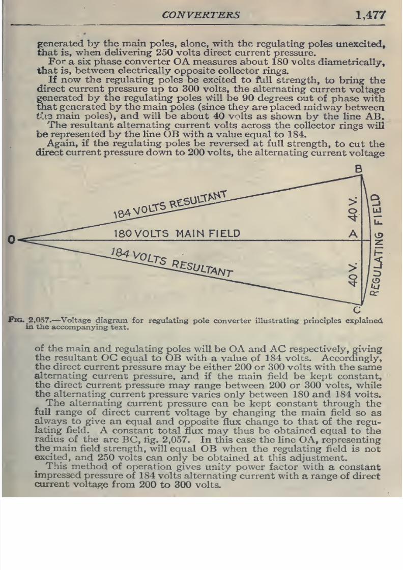
8/20/2019 electrical guide 5.pdf
http://slidepdf.com/reader/full/electrical-guide-5pdf 223/343
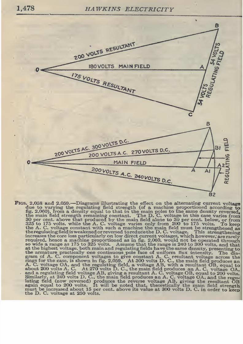
8/20/2019 electrical guide 5.pdf
http://slidepdf.com/reader/full/electrical-guide-5pdf 224/343
1,478
HAWKINS
ELECTRICITY
MAIN
FIELD
^^2)2^2.0.
Al
C.
A2
82
Pigs.
2,058
and
2,059.
—
Diagrams illustrating
the
effect
on
the
alternating
current
voltaga
due
to
varying the regulating
field
strength (of
a
machine
proportioned
according
to
fig.
2,060),
from
a
density equal
to
that
in the
main
poles to
thesame
density
reversed,
the main field
strength
remaining constant. The
D.
C.
voltage
in this
case
varies
from
30
per
cent,
above
that
produced
by
the
main
field
alone to
30
per cent,
below,
or
from
325
to
175
volts, while
the
A. C.
voltage
varies
only
from
200
to
175
volts.
To
keep
the
A.
C.
voltage
constant
with
such
a
machine the
main
field
must
be
strengthened
as
thereguladngfieldisweakenedorreversed
toreducethe
D.
C.
voltage.
This
strengthening
increases the
core
loss particularly
on
low
direct
cvurerit voltages,
which
however;
are
rarely
required,
hence
a
machine
proportioned as
in
fig.
2,060,
would not
be
operated
through
so wide
a
range as
175
to
325
volts.
Assume
that
the range
is 240
to 300
volts,
and
that
at
the
highest
voltage, both
main and regulating fields have the
same
density,
presenting
to
the armature
practically
one
continuous pole
face of uniform fiux
intensity.
The
dia-
gram of A.
C. component voltages
to give
constant
A.
C.
resultant
voltage
across
the
rings for the
case, is shown
in
fig.
2,059.
At
300
volts
D.
C,
the
main
field
produces
an
A. C.
voltage
OA,
and
the
regulating field,
a
voltage
AB, with
a resultant
OB,
equal
to
about
200
volts
A.
C.
At 270 volts
D.
C,
the
main
field
produces
an
A. C.
voltage
OA,
.
and a
regulating
field
voltage AB, giving
a resultant A. C. voltage
OB,
equal
to
200
volts.
Similarly,
at
240 volts
D.
C,
the
main
field
produces
an
A. C.
voltage
OA,
and
the
regU'
lating
field
(now reversed)
produces
the
reverse voltage
AB,
giving
the
resultant
OB
again
equal to
200
volts.
It
will
be noted
that, theoretically
the
main field
strength
must be increased
about
15
per
cent,
above
its value at 300 volts
D. C.
in
order
to
keep
the
D. C.
voltage
at
250
volts.
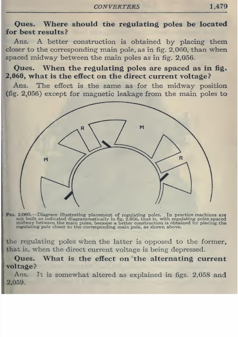
8/20/2019 electrical guide 5.pdf
http://slidepdf.com/reader/full/electrical-guide-5pdf 225/343
CONVERTERS 1,479
Ques,
Where
should
the regulating
poles be
located
for best
results
?
Ans.
A
better
construction
is
obtained
by
placing
them
closer
to
the
corresponding
main
pole,
as
in
fig.
2,060,
than
when
spaced
midway
between
the
main
poles
as in
fig.
2,056.
Oues.
When
the regulating poles
are
spaced as
in
fig,
2,060,
what
is
the
effect
on
the direct
current
voltage?
Ans.
The
effect
is
the
same
as for
the midway
position
(fig.
2,^056)
except
for magnetic leakage
from
the main
poles
to
Pig.
2,060.—Diagram
illustrating
placement of regulating
poles.
_
In
practice
machines
are
not
built
as indicated
diagrammatically
in fig.
2,056,
that
is,
with
regulating
poles
spaced
midway between
the
main
poles, because
a better
construction
is obtained by placing
the
regulating pole
closer
to
the
corresponding
main
pole,
as shown above.
the
regulating
poles
when
the
latter
is
opposed to the former,
that
is, when
the
direct
current voltage
is
being depressed.
Oues.
What
is
the
effect
on
the
alternating
current
voltage?
Ans.
It
is
somewhat
altered
as
explained
in
figs.
2,058 and
2,059.
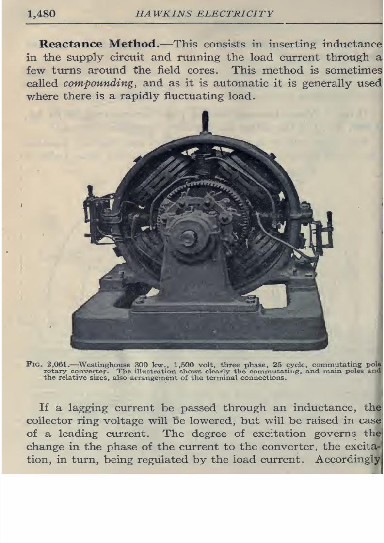
8/20/2019 electrical guide 5.pdf
http://slidepdf.com/reader/full/electrical-guide-5pdf 226/343
1,480
HAWKINS
ELECTRICITY
Reactance
Method.—
This consists in inserting
inductance
in
the
supply
circuit
and running the
load
current
through a
few
turns
around
the
field
cores.
This
method
is
sometimes
called
compounding,
and
as
it
is
automatic
it is
generally
used
where
there
is a rapidly fluctuating
load.
Pig. 2,061.
—
^Westinghouse
300
kw., 1,500
volt, three phase,
25 cycle,
commutating
pola
rotary
converter. The illustration shows clearly the commutating,
and
main
poles
and
the
relative
sizes,
also arrangement
of
the
terminal
connections.
If
a lagging
current
be
passed
through
an
inductance,
the
collector
ring
voltage
will
be
lowered, but will be
raised
in case
of
a
leading
current.
The
degree
of
excitation
governs
the
change
in
the
phase
of the
current
to the converter,
the
excita-
tion,
in
turn, being
regulated
by the
load
current.
Accordingly
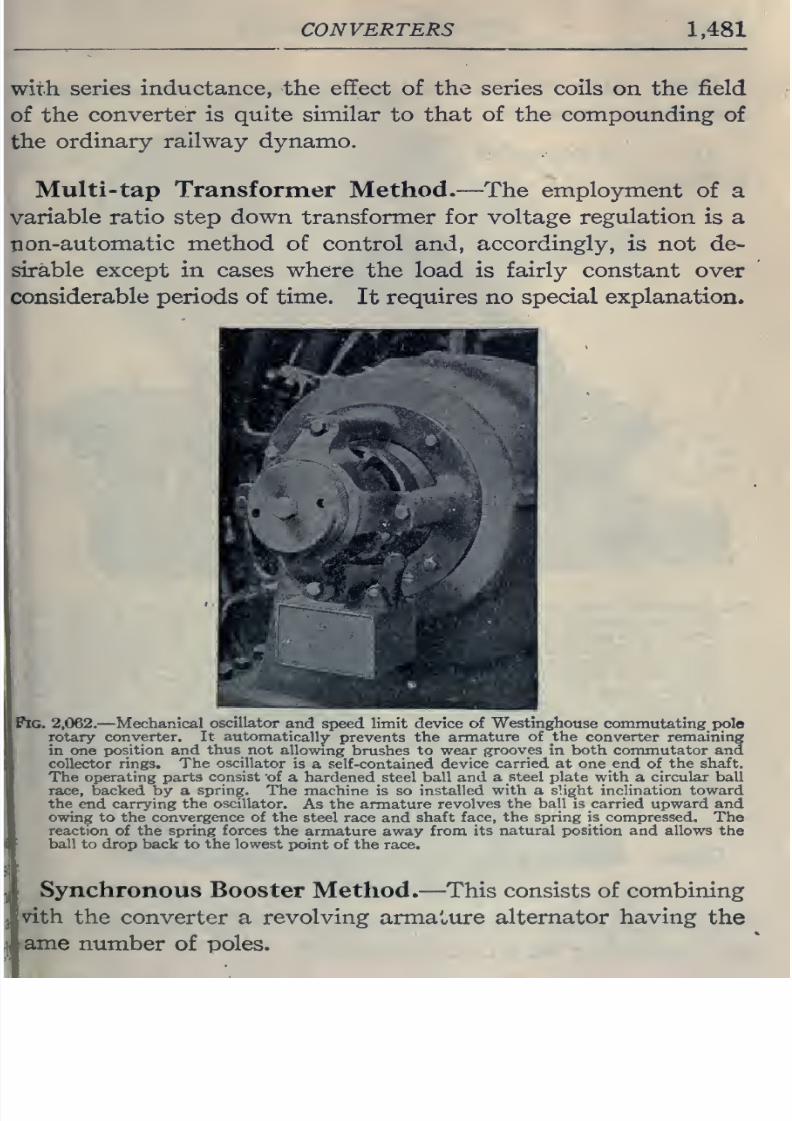
8/20/2019 electrical guide 5.pdf
http://slidepdf.com/reader/full/electrical-guide-5pdf 227/343
CONVERTERS
1,481
ith
series
inductance,
the
effect
of
the
series coils
on
the
field
of
the
converter
is
quite similar
to
that
of
the
compounding
of
the
ordinary
railway
dynamo.
Multi-tap Transformer
Method.—The employment
of
a
ratio
step
down
transformer for voltage regulation is
a
on-automatic
method
of control and,
accordingly,
is
not
de-
sirable
except in
cases where
the
load
is
fairly
constant
over
onsiderable periods
of
time.
It
requires no
special
explanation.
^^^^^^7^^*^^^
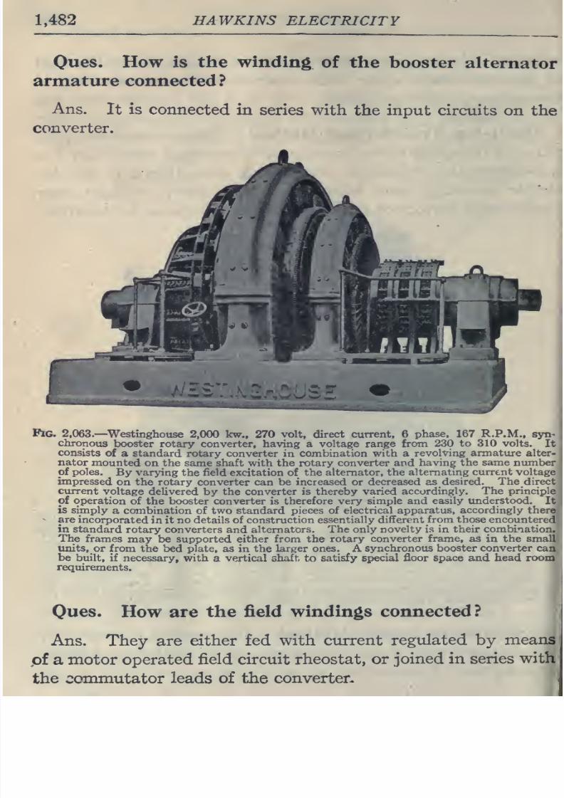
8/20/2019 electrical guide 5.pdf
http://slidepdf.com/reader/full/electrical-guide-5pdf 228/343
1.482
HAWKINS
ELECTRICITY
Ques. How
is
the winding
of
the
booster
alternator
armature
connected?
Ans.
It
is
connected
in
series with
the
input
circuits
on
the
converter.
Pig.
2,063.—
Westinghouse
2,000
kw., 270
volt, direct current.
6
phase.
167
R.P.M.,
syn-
chronous
booster
rotary converter,
having
a
voltage
range from
230
to
310
volts.
It
consists
of
a
standard
rotary
converter
in
combination with a
revolving armature
alter-
nator
mounted
on the
same
shaft
with
the rotary
converter
and
having
the same number
of poles.
By
varying
the field
excitation
of the
alternator, the
alternating
current
voltage
impressed
on
the
rotary
converter
can be
increased
or
decreased as
desired.
The direct
ctirrent
voltage
delivered
by
the
converter
is thereby
varied
accordingly.
The
principle
of
operation
of
the
booster
converter
is
therefore
very
simple
and
easily
understood.
It
is simply
a
combination
of two standard
pieces
of
electrical
apparatus,
accordingly
there
are
incorporated
in
it
no
details
of
construction
essentially
different
from
those
encountered
in standard
rotary converters
and
alternators.
The
only novelty is
in
their
combination.
The
frames
may
be
supported
either
from
the rotary
converter frame, as
in the
small
units,
or from
the bed
plate,
as
in
the
larger
ones. A
synchronous
booster
converter
can
be built,
if necessary, with
a
vertical
shaft
to
satisfy
special floor space
and
head room
requirements.
Ques.
How
are
the
field
windings
connected?
Ans.
They
are
either
fed
with
current
regulated
by
means
pf
a
motor operated
field
circuit rheostat, or
joined in series
with
the
commutator
leads of the
converter-
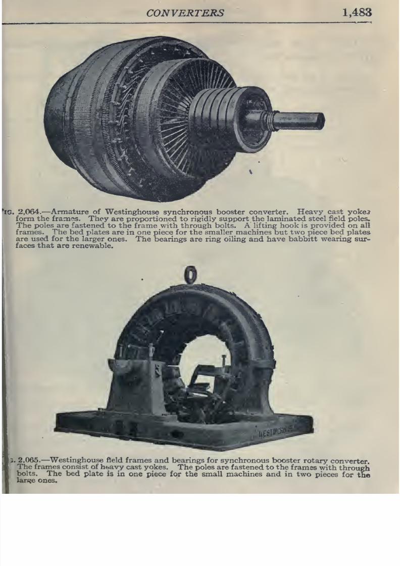
8/20/2019 electrical guide 5.pdf
http://slidepdf.com/reader/full/electrical-guide-5pdf 229/343
CONVERTERS
1,483
2,064.
—Armature of
Westinghouse synchronous booster converter.
Heavy cast yokej
form
the frames. They
are
proportioned to
rigidly support the laminated steel
field
poles.
The
poles are
fastened
to
the
frame with
through
bolts.
A lifting
hook
is provided
on all
frames.
The
bed plates
are
in
one piece
for
the
smaller
machines
but
two
piece
bed
plates
are
used for the
larger
ones.
The bearings are
ring oiling
and
have
babbitt wearing sur-
faces
that
are
renewable.
.
2,065.
—
^Westinghouse
field
frames
and
bearings
for
synchronous
booster
rotary
converter.
The frames
consist
of
heavy
cast
yokes.
The
poles
are
fastened to the
frames
with
through
bolts.
The
bed
plate
is
in one piece
for the small
machines
and in two
pieces
for
the
lan?e
ones.
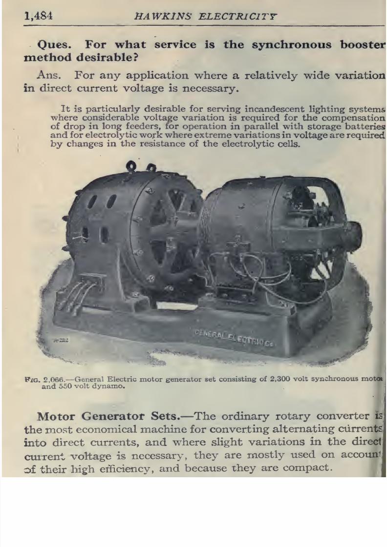
8/20/2019 electrical guide 5.pdf
http://slidepdf.com/reader/full/electrical-guide-5pdf 230/343
1,484
HAWKINS
ELECTRICITY
Oues.
For
what
method
desirable?
service
is the
synchronous
booster
Ans. For any
application
where
a relatively wide
variation
in
direct
current voltage is
necessary.
It
is
particularly desirable
for serving
incandescent lighting
systems
where
considerable
voltage
variation
is
required
for
the
compensation
of
drop
in
long feeders, for
operation
in
parallel
with
storage batteries
and
for electrolytic
work
where
extreme variations in
voltage
are
required
by
changes in
the
resistance
of the
electrolytic
cells.
PiG.
2,066.—
General
Electric
motor
generator
set
consisting of 2,300
volt
synchronous motot i
and
550
volt dynamo.
Motor
Generator
Sets.
—
The
ordinary
rotary
converter
is
the
most
economical machine for
converting
alternating
currents
into
direct
currents,
and
where slight
variations
in the
direct
current
voltage
is
necessary,
they
are
mostly
used
on
accouni
of
their
high
efficiency,
and
because
they
are
compact.
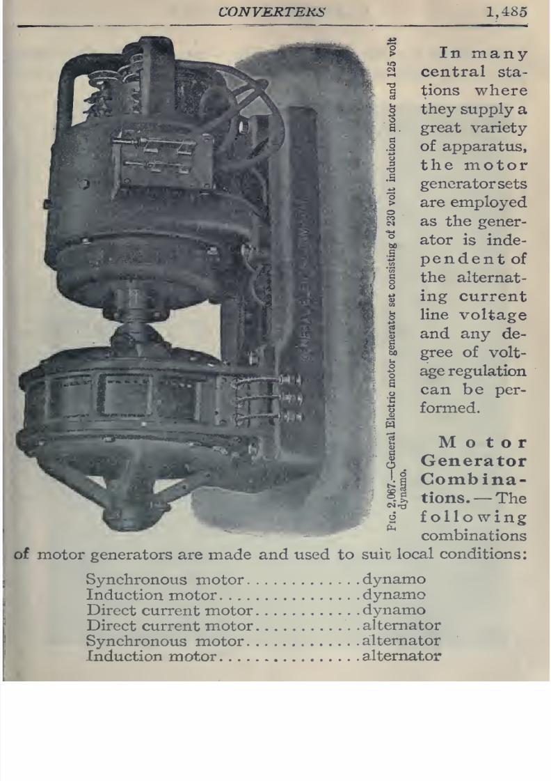
8/20/2019 electrical guide 5.pdf
http://slidepdf.com/reader/full/electrical-guide-5pdf 231/343
CONVERTEKS
1,485
>
In
many
2
central
sta-
1
tions
where
S
they supply
a
a.
great
variety
I
of apparatus,
I
the
raotor
';^
generator
sets
>
are
employed
?5
as
the
gener-
°
ator
is
inde-
I
pendent
of
§
the
alternat-
I
ing
current
S
line
voltage
i
and any
de-
M
gree
of
volt-
I
age
regulation
Z
can
be per-
1
formed.
I
Motor
I
Generator
^^^
j:i
Combina-
*'' ''^'
il
tions.
—
The
>
^
following:
4V'.
-.5,.^
combinations
of motor
generators are made and
used
to
suit
local conditions:
Synchronous
motor
dynamo
Induction
motor
dynamo
Direct
current motor
dynamo
Direct
current
motor
.alternator
Synchronous
motor
alternator
Induction motor
alternator
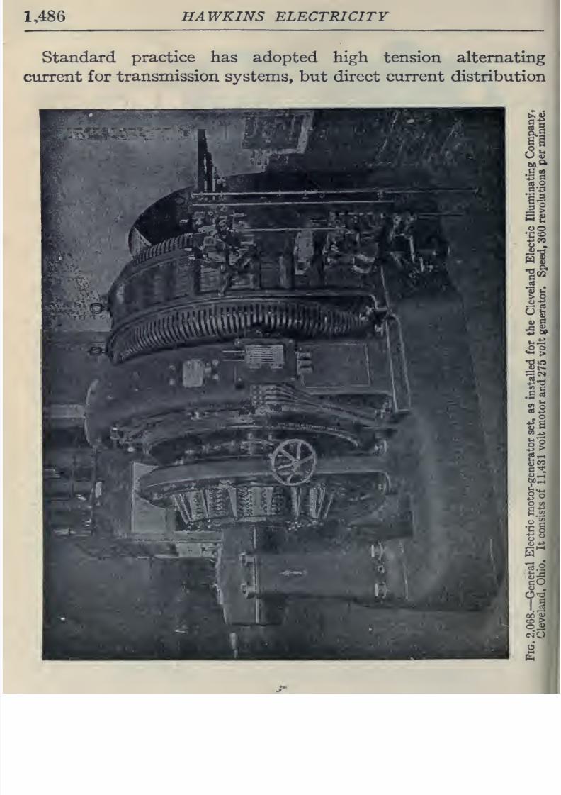
8/20/2019 electrical guide 5.pdf
http://slidepdf.com/reader/full/electrical-guide-5pdf 232/343
1486
HAWKINS
ELECTRICITY
Standard
practice
has
adopted high
tension
alternating
current
for
transmission
systems,
but
direct
current
distribution
C
m
tt
o
11
•-•
u
OO
•no
4J
R
2o
w
So
o
«
6
8/20/2019 electrical guide 5.pdf
http://slidepdf.com/reader/full/electrical-guide-5pdf 233/343
CONVERTERS
1,487
is
very
frequently
used.
This
is
particularly true
where
alter-
nating
current
apparatus
has
been
introduced
in old
direct
current
lighting
systems.
The
synchronous motor
or the
induction
motor
connected
to
a
generator stands next in importance
to the rotary
converter
because
it
is
easy
to
operate and the pressure
may
be
changed
by
a rheostat
placed
in the
field
circuit of
the generator.
The
line
wires carrying
fuU
voltage can usually
be
connected
direct to
the
motor and
thus
do
away
with
the
necessary
step-
down
transformer
required
by
the
rotary.
Ques.
What
is
the
behavior
of
a
rotary
converter
when
hunting?
Ans.
It
is
liable
to
flash
over
at the
direct
current
brushes,
which
is
common
in
high
frequency converters
where
there
are
a
great
number
of
poles
and
the
brushes
are
necessarily
spaced
close
together
around the
commutator.
Ones.
Is
this
fault
so pronounced
with
motor
gener-
ator
sets?
Ans.
The
motor
generator
operating
on a
high
frequency
circuit, the
generator
can
be
designed with
a few
poles
and
the
brushes
set
far apart
which
will
greatly reduce
the chance
of
flashing
over.
A
synchronous
motor
will
drive
a
generator
at
a
constant
speed
during
changes
in
load on
it,
and
by
having
a
field regulating
resistance
it can
be used
to improve
the
power
factor
of
the system.
When
an
induction
motor is used its
speed drops
off slowly
as the
load
comes
on
the
generator,
and
it
is
necessary
to
regulate
the
voltage
of
the
generator
by
means of
a
field rheostat, or,
compound
wound
machines
may
be used.
While
an induction
motor requires
no
separate excitation
of
the
field
magnets
like
the
synchronous motor, its effect on
the
power
factor
of
the
system
is
undesirable.
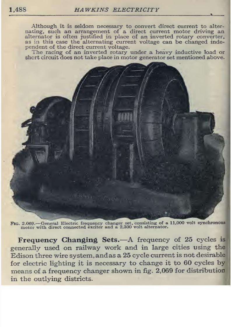
8/20/2019 electrical guide 5.pdf
http://slidepdf.com/reader/full/electrical-guide-5pdf 234/343
1.488
HAWKINS
ELECTRICITY
Although
it is
seldom
necessary
to
convert direct
current to
alter-
nating,
such
an
arrangement
of
a
direct
current
motor
driving
an
alternator
is
often
justified
in
place
of an
inverted rotary converter,
as
in this
case
the alternating
current
voltage can be
changed
inde-
pendent
of
the
direct
current
voltage.
The
racing
of
an
inverted
rotary
under
a
heavy
inductive load
or
shcrt circuit does
not
take place in motor
generator
set
mentioned
above.
.
Pig.
2,069.
—
General
Electric
frequency
changer
set, consisting
of
a 11,000
volt
synchronous
motor
with
direct
connected
exciter and a
2,300
volt
alternator.
Frequency
Changing
Sets.
—A
frequency
of
25
cycles
is
generally
used
on
railway
work
and
in
large
cities
using
the
Edison
three
wire
system,
andas
a
25
cycle
current
is
not
desirable
for
electric
lighting
it
is
necessary to
change
it
to
60
cycles by
means
of
a
frequency
changer
shown
in fig.
2,069
for
distribution
in the
outlying
districts.
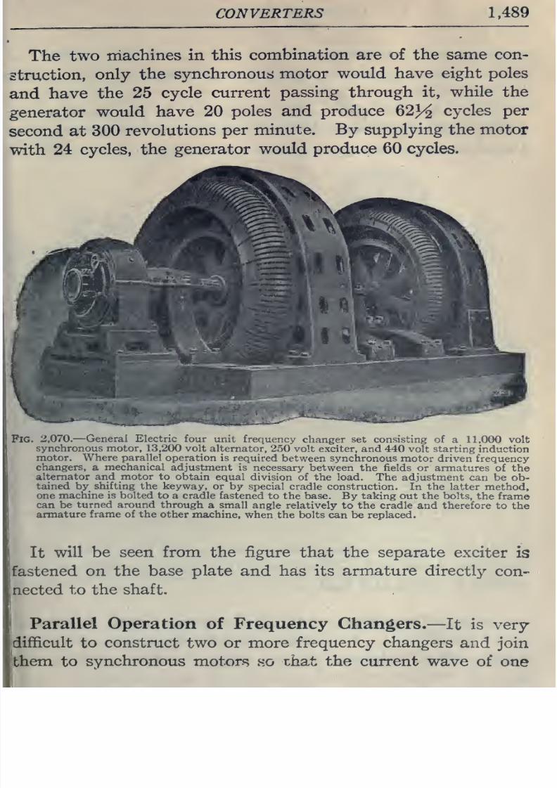
8/20/2019 electrical guide 5.pdf
http://slidepdf.com/reader/full/electrical-guide-5pdf 235/343
CONVERTERS
1.489
The
two
machines
in
this
combination
are
of
the same
con-
struction,
only
the
synchronous motor
would
have
eight poles
and
have
the
25
cycle
current
passing
through it,
while the
generator
would have
20
poles
and produce
62^^
cycles
per
second at
300
revolutions
per
minute.
By supplying
the
motor
with
24
cycles,
the
generator
would
produce 60 cycles.
Fig.
2,070.
—
General Electric four
unit
frequency
changer
set
consisting of
a 11,000 volt
synchronous motor,
13,200
volt
alternator, 250
volt exciter,
and 440
volt starting induction
motor.
Where parallel
operation is
required
between synchronous
motor driven frequency
changers,
a
mechanical adjustment
is necessary
between
the fields
or armatures
of the
alternator
and
motor
to
obtain
equal
division
of
the
load.
The
adjustment
can
be
ob-
tained
by
shifting
the
keyway,
or
by
special cradle
construction. In
the
latter
method,
one
machine
is bolted
to a
cradle
fastened
to the base.
By
taking out the bolts,
the
frame
can
be turned
around
through
a small
angle
relatively
to
the cradle
and therefore
to
the
armature
frame of
the
other machine,
when
the bolts can be replaced.
It
will
be
seen from
the figure
that
the separate
exciter
is
fastened
on the
base
plate
and
has its
armature
directly
con-
nected
to the shaft.
Parallel Operation
of
Frequency Changers.
—
It
is very-
difficult
to
constru.ct
two
or
more
frequency changers
and
join
them
to
synchronous
motor-s
so
that the
current
wave
of one
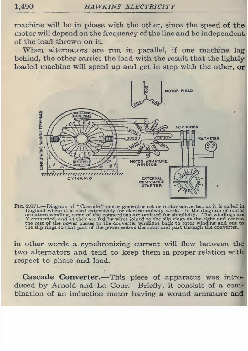
8/20/2019 electrical guide 5.pdf
http://slidepdf.com/reader/full/electrical-guide-5pdf 236/343
1,490
HAWKINS ELECTRICITY
machine
will
be in phase with
the
other,
since the
speed
of the
motor
will depend
on
the
frequency
of
the
line
and
be
independent
of the
load thrown on
it.
When
alternators
are run. in
parallel,
if
one
machine
lag
behind,
the
other
carries
the
load
with the result
that the
lightly
loaded
machine
will
speed
up
and
get
in
step
with
the
other,
or
MOTOR
FIELD
*
—
vAQ.QQ
f
DYNAMO
^^^r-^'f
'os^^
MOTOR
ARMATURE
WINDING
EXTERNAt
RESISTANCE
STARTER
Fig.
2,071.
—Diagram of
Cascade motor
generator
set
or
motor converter,
as
It is called
in
England
where
it
is
used extensively
for electric
railway work. In
the
diagram
of
motor
armature
winding,
some
of
the
connections
are
omitted
for simplicity.
The
windings
are
Y
connected,
and
as they
are
fed
by wires
joined
to
the
slip rings
at the
right and
center,
the
rest of the power
passes
to
the
converter
windings back to rotor
winding and out
to
the
slip
rings so
that part of the power
enters the rotor
and
part
through
the
converter.
in
other
words a synchronizing
current
will flow between the
two
alternators
and
tend
to
keep
them
in
proper
relation with
respect
to
phase and
load.
Cascade
Converter.
—
This piece of
apparatus
was intro-
duced
by
Arnold and
La
Cour.
Briefly,
it
consists
of
a
com-
bination
of
an induction
motor
having
a wound
armature
and
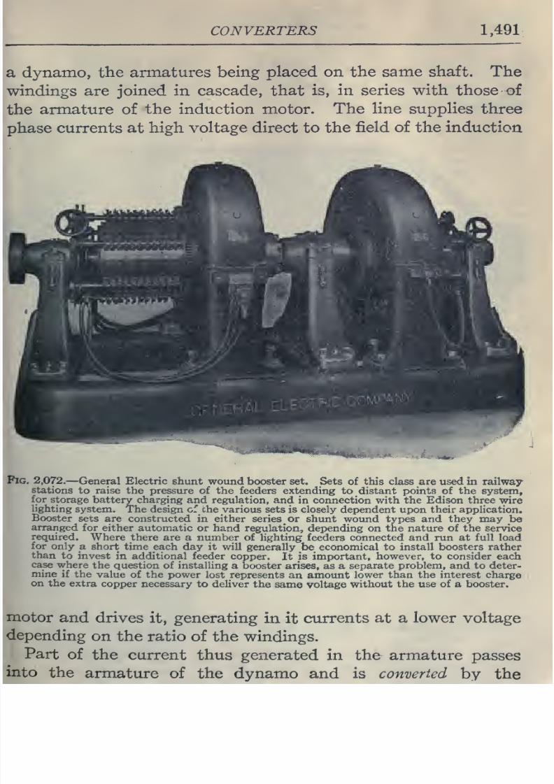
8/20/2019 electrical guide 5.pdf
http://slidepdf.com/reader/full/electrical-guide-5pdf 237/343
CONVERTERS
1,491
dynamo,
the armatures
being
placed on the
same shaft. The
are
joined in
cascade,
that
is,
in
series with
those
of
armature of
the
induction
motor.
The
line supplies
three
hase
currents
at
high voltage
direct
to
the
field
of the
induction
2,072.
—
General
Electric
shunt
wound
booster
set. Sets
of
this
class
are used in railway-
stations
to raise
the pressure of the feeders extending
to distant
points
of the
system,
for
storage
battery charging
and regulation, and
in connection
with
the Edison three
wire
lighting
system.
The
design
cf
the
various
sets
is closely
dependent upon
their application.
Booster
sets are
constructed
in
either
series
or shtmt wound
types
and they may
be
arranged
for either automatic
or
hand
regulation, depending
on
the nature
of
the
service
required.
Where there
are a
number
of
lighting feeders connected
and run at
full
load
for
only
a short
time each day
it will
generally
be_
economical to
install
boosters rather
than
to
invest
in additional feeder
copper.
It
is
important,
however, to consider
each
case
where
the
question
of installing
a
booster
arises,
as a
separate problem, and
to
deter-
mine
if
the
value
of
the
power lost
represents
an amount
lower
than the interest
charge
on
the
extra
copper
necessary
to
deliver
the
same voltage
without
the
use
of
a
booster.
and
drives
it,
generating
in
it
currents
at a lower voltage
on
the
ratio
of
the windings.
Part
of
the current
thus
generated
in
the armature
passes
the
armature
of the dynamo and is
converted
by
the
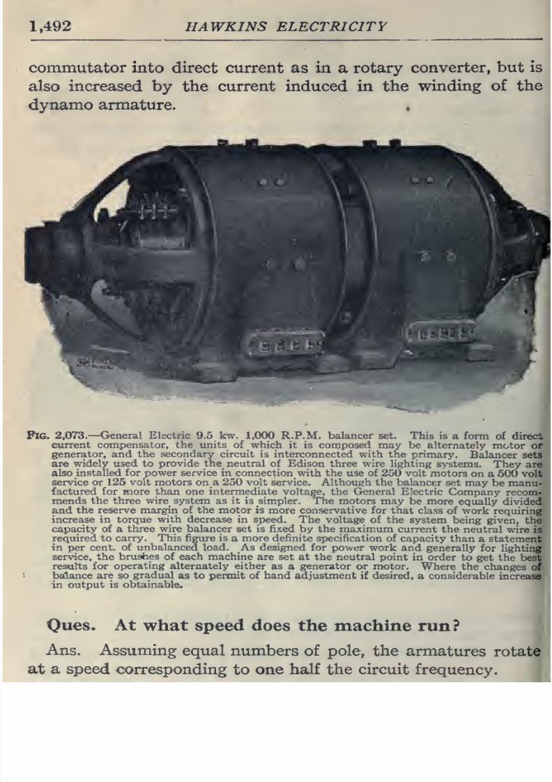
8/20/2019 electrical guide 5.pdf
http://slidepdf.com/reader/full/electrical-guide-5pdf 238/343
1,492
HAWKINS
ELECTRICITY
commutator into
direct
current
as
in
a
rotary
converter,
but
is
also
increased
by
the
current induced
in
the
winding of the
dynamo armature.
Fig.
2,073.—General Electric 9.5
kw.
1,000 R.P.M.
balancer
set.
This
is
a form
of
direct
current
compensator, the
units of
which
it
is
composed
may
be alternately
motor or
generator,
and
the
secondary
circuit is interconnected with the
primary.
Balancer
sets
are
widely used to provide
the
neutral
of
Edison
three
wire lighting
systems.
They are
also
installed
for
power
service
in
connection
with
the
use
of
250
volt
motors
on a
500
volt
service
or
125
volt
motors on
a
250 volt
service.
Although the
balancer
set
may
be
manu-
factured for more than
one
intermediate
voltage,
the
General
Electric
Company
recom-
mends
the
three
wire
system
as
it is simpler. The
motors may
be more
equally
divided
and
the reserve
margin of
the
motor
is
more conservative
for that
class
of
work requiring
increase in torque
with decrease
in speed. The
voltage
of the system
being
given,
the
capacity
of
a
three wire
balancer set is fixed
by the
maximum
current
the
neutral wire
is
required
to
carry.
This
figure
is
a
more definite
specification
of
capacity
than
a statement
in
per
cent, of
unbalanced
load.
As designed
for power
work
and generally
for
lighting
service,
the
brushes
of each
machine
are
set
at
the
neutral
point
in
order
to get
the
best
results
for
operating
alternately
either
as
a
generator
or motor.
Where
the
changes
of
balance are
so
gradual
as to
permit of
hand adjustment
if
desired,
a
considerable
increase
in
output
is
obtainable.
Oues.
At
what speed does the machine
run?
Ans.
Assuming
equal
numbers
of
pole,
the
armatures
rotate
at
a
speed
corresponding
to
one half the circuit
frequency.
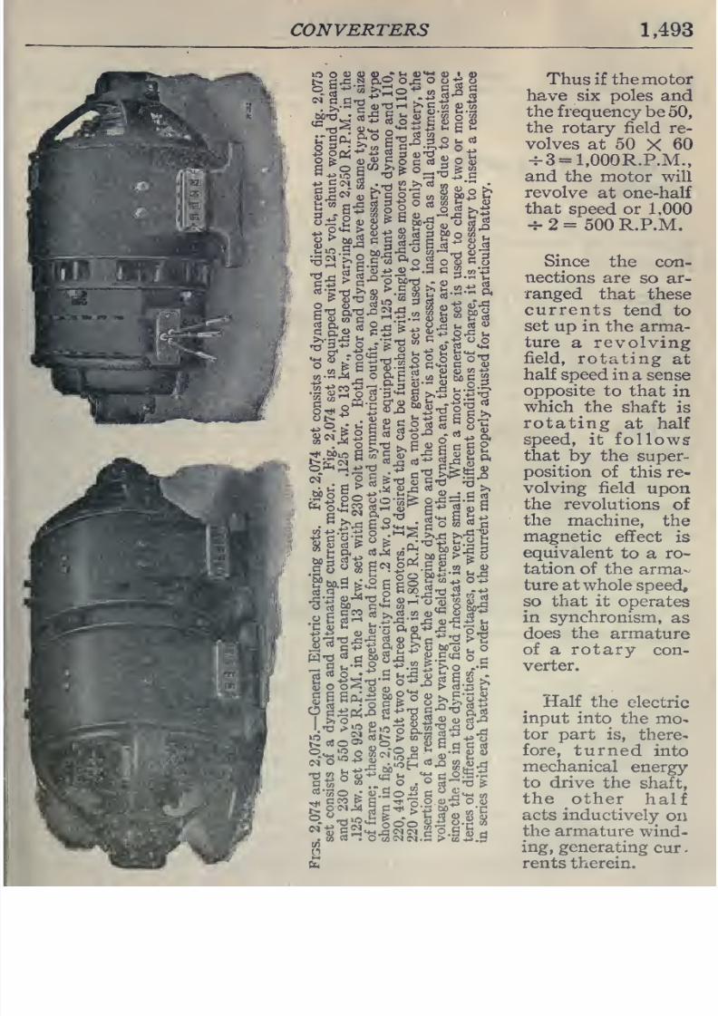
8/20/2019 electrical guide 5.pdf
http://slidepdf.com/reader/full/electrical-guide-5pdf 239/343
CONVERTERS
1,493
P
>
«
P
«
M-f^
,,
O
rt
S
llil^llliFil
^
rt
5
5-^4)-^.
S
C
^
to
-+3
'13
w
R ^.-t^
O
sa
•
2
^'^
ixS
i>
§
a
c
g
.*^
>^jc
S2
•
5S^ fe
rt-S
^
,,
O
W
TO
CJ
^
-
-•CL,
rt
cd
o
' ^^
H
»^,c:
5
tj
c
to
-
Thus if the motor
have
six
poles
and
the
frequency
be
50,
the
rotary field
re-
volves
at
50
X
60
4-3
=
l,000R.P.M.,
and
the
motor
will
revolve
at
one-half
that
speed
or 1,000
-r- 2
=
500 R.P.M.
Since
the con-
nections
are
so
ar-
ranged
that
these
currents
tend
to
set
up in
the arma-
ture
a
revolving
field,
rotating
at
half
speed
in
a
sense
opposite
to that
in
which
the
shaft
is
rotating
at
half
speed,
it followsr
that
by the
super-
position
of
this re-
volving
field
upon
the
revolutions
of
the
machine,
the
magnetic
effect
is
equivalent
to
a
ro-
tation
of
the
arma-
ture
at
whole
speed,
so that it
operates
in
synchronism,
as
does
the
armature
of
a
rotary
con-
verter.
Half
the
electric
input into
the
mo-
tor
part
is,
there-
fore,
turned
into
mechanical
energy
to
drive
the
shaft,
the
other
half
acts
inductively
on
the
armature
wind-
ing,
generating
cur.
rents therein.
8/20/2019 electrical guide 5.pdf
http://slidepdf.com/reader/full/electrical-guide-5pdf 240/343
1,494
HAWKINS
ELECTRICITY
As
to the
dynamo
part
it
is
half
generator,
receiving
mechanical
power
by
transmission
along
the shaft
to
furnish
half
its output,
and
it
IS
half
converter, turning
the
currents
received
from
the
armature
into
direct
current
delivered
at
the brushes.
Ques. What
action
takes
place
in
the motor
armature
winding?
Ans.
Since
it
runs
at
one-half
synchronous
speed, it
generates
alternating
current
of
half
the supply current
frequency,
de-
livering
these
to
the armature
of
the dynamo.
Ques.
What
claim
is
made
for
this
type
of apparatus?
Ans.
The
cost
is
said
to
be less
than
a motor
generator
set,
and
it is
claimed
to
be
self-synchronizing
and
to
require
no
special starting
gear,
also to
be
2.5
per
cent,
more efficient
than
a
motor
generator.
Ones.
How
is
the machine
started from
the
high
pressure
side?
Ans.
The
field winding
is connected
directly
to
the
high
pressure
leads. The three slip
ring brushes
are
connected
with
external
resistances which are used
while
starting, the
external
resistances
being
gradually
cut out
of
the circuit
as
the
machine
comes
up
to
speed
(the
same
as with
an
ordinary slip
ring
motor).
Ques.
How does
a
cascade
converter compare with
a|
synchronous
converter?
Ans. It
is about
equally
expensive
as
the
synchronoi
converter
with its
necessary
bank
of
transformers,
but is
about
one
per
cent,
less
efficient.
It is
claimed
to be
more
desirabl
for
frequencies
above
dO
on
account
of
the
improved commu-l
tation
at the
low frequency used
in
the
dynamo
member.
F(
lower
frequencies
the
synchronous
converter
is
preferable.
8/20/2019 electrical guide 5.pdf
http://slidepdf.com/reader/full/electrical-guide-5pdf 241/343
RECTIFIERS
1,495
CHAPTER
LIV
RECTIFIERS
The
purpose of
a
rectifier is
to
change alternating
current
into
a
uni-directional or pulsating
current.
There
are
several
classes
of
apparatus
to which
the
term
rectifier
may
be
applied, as
1.
Mechanical
rectifiers;
2.
Electrolytic rectifiers;
3.
Mercury
vapor
rectifiers,
or,
mercury
arc
rectifiers;
4.
Electro-magnetic
rectifiers.
Mechanical
Rectifiers.
—
By
definition,
a mechanical
rectifier
is
a form
of commutator
operating
in synchronism
with the
generator
and
commutating or rectifying
the
negative
waves
of
the
alternating
current
as
shown
graphically in
figs.
2,076
and
2,078.
The essential
features
of
construction
are
shown in
fig.
2,079.
Oues.
Mention
some
application
of
a mechanical
rectifier.
Ans. It
is
used on a
compositely
excited
alternator
as il-
lustrated
on
page
1
,
192.
Electrolytic Rectifiers.
—
If
two
metals be placed
in
an
elec-
trolyte
and
then subjected
to
a
definite
difference
of
pressure,
they
will
(under
certain
conditions)
offer
greater resistance
to
the
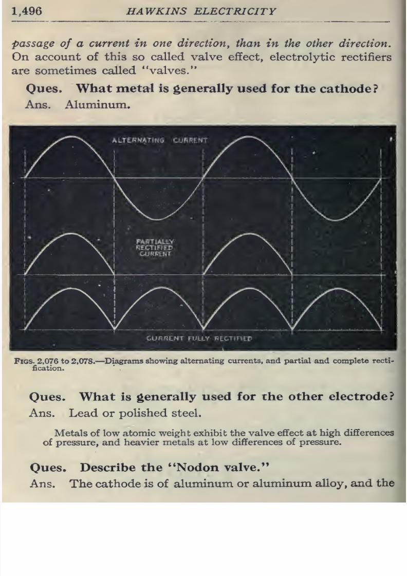
8/20/2019 electrical guide 5.pdf
http://slidepdf.com/reader/full/electrical-guide-5pdf 242/343
1,496
HAWKINS ELECTRICITY
passage
of
a
current
in
one
direction^
than
in
the other
direction.
On account
of
this
so
called
valve effect,
electrolytic
rectifiers
are
sometimes
called
valves.
Oues.
What
metal
is
generally
used
for
the
cathode?
Ans.
Aluminum.
Figs.
2,076
to
2,078.—
Diagrams showing
alternating
currents,
and partial and complete
recti-
fication.
Oues.
What
is
generally used
for
the other
electrode?
Ans.
Lead
or
polished
steel.
Metals of
low
atomic weight exhibit the
valve
effect at
high
differences
of
pressure,
and
heavier
metals
at
low
differences
of
pressure.
Oues.
Describe
the
'*Nodon
valve.
Ans.
The
cathode is of
aluminum or
aluminum
alloy,
and
the
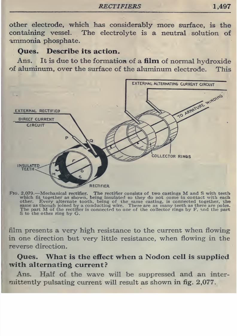
8/20/2019 electrical guide 5.pdf
http://slidepdf.com/reader/full/electrical-guide-5pdf 243/343
RECTIFIERS
1,497
other
electrode,
which
has
considerably
more
surface,
is
the
containing vessel. The
electrolyte
is a
neutral
solution
of
ammonia
phosphate.
Ques.
Describe
its
action.
Ans.
It
is due
to
the
formation
of
a
film
of
normal
hydroxide
of
aluminum,
over
the
surface
of
the
aluminum
electrode.
This
COLLECTOR
RINSS
INSULATED
TEETH
'
RECTIFIER
Fig.
2,079.
—Mechanical
rectifier.
The rectifier
consists
of
two
castings
M
and
S
with
teeth
which
fit
together
as
shown, being
insulated
so they
do
not
come in contact with
each
other.
Every alternate
tooth,
being of
the same casting, is
connected
together, the
same
as
though
joined
by
a
conducting
wire.
There
are
as
many
teeth
as there
are
poles.
The part M of
the rectifier
is connected
to
one of the
collector
rings
by
F, and the part
S to
the
other
ring
by
G.
film
presents
a
very high
resistance
to
the
current
when
flowing
in one direction
but
very
little
resistance,
when
flowing
in
the
reverse
direction.
Ovies.
What
is
the
effect
when
a
Nodon
cell
is
supplied
with
alternating
current?
Ans. Half
of the
wave
will
be
suppressed and an
inter-
mittently
pulsating
current
will
result
as
shown in
fig.
2,077.
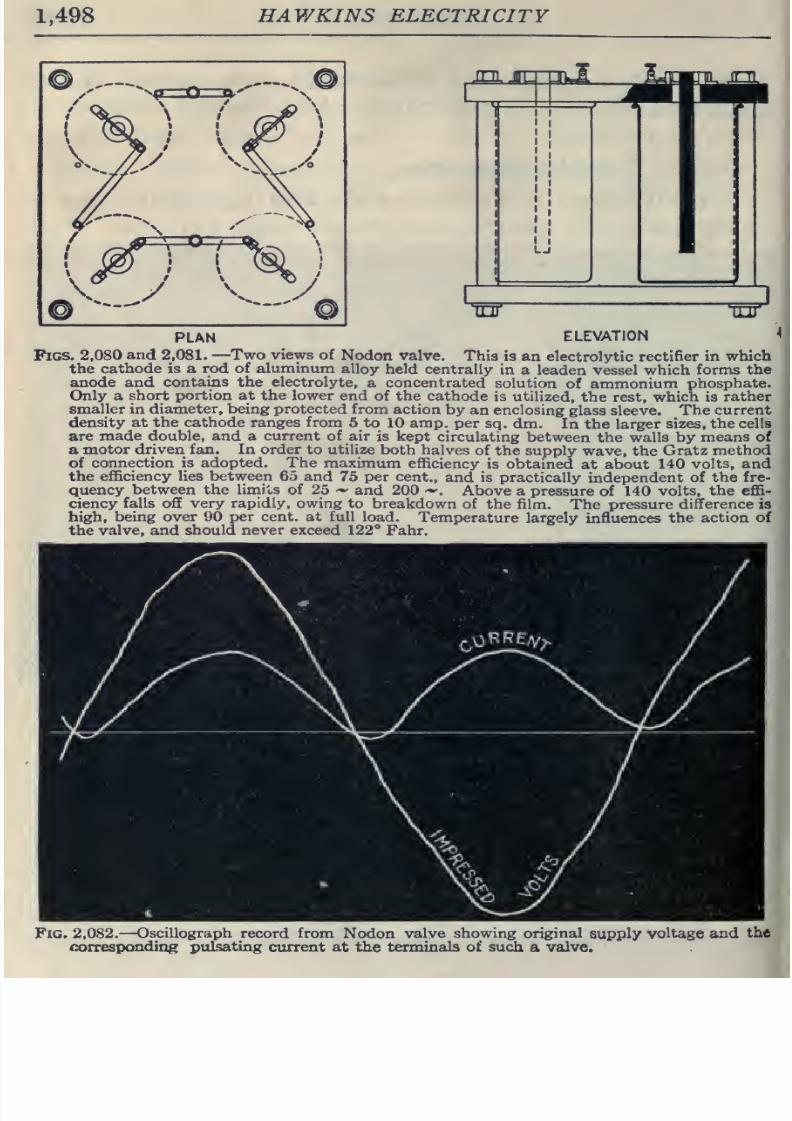
8/20/2019 electrical guide 5.pdf
http://slidepdf.com/reader/full/electrical-guide-5pdf 244/343
1,498
HAWKINS ELECTRICITY
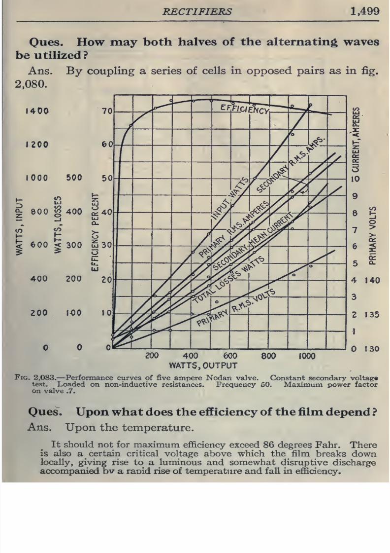
8/20/2019 electrical guide 5.pdf
http://slidepdf.com/reader/full/electrical-guide-5pdf 245/343
RECTIFIERS
1,499
Ones.
How
may
both
halves
of
the
alternating
waves
be
utilized ?
Ans.
By
coupling
a series
of
cells
in
opposed
pairs as
in
fig.
2,080.
1400
1200
lOOO
500
CL
eoo
S
400
:<
600
^
300
Sao
400 200
200
lOO
200
400
600
WATTS, OUTPUT
Fig.
2,083.
—Performance
curves of
five
ampere Nodan
valve.
Constant
secondary
voltag*
test.
Loaded
on non-inductive
resistances. Frequency 50,
Maximum power
factor
on
valve
.7.
Oues.
Upon
what does
the efficiency of
the film
depend
?
Ans.
Upon the
temperature.
It
should
not
for
maximum efficiency
exceed
86
degrees
Fahr.
There
is
also
a
certain critical
voltage above which the film
breaks
down
locally,
giving
rise
to
a
luminous
and
somewhat
disruptive
discharge
accompanied
bv
a
raoid rise
of
temperature and
fall in
efficiency.
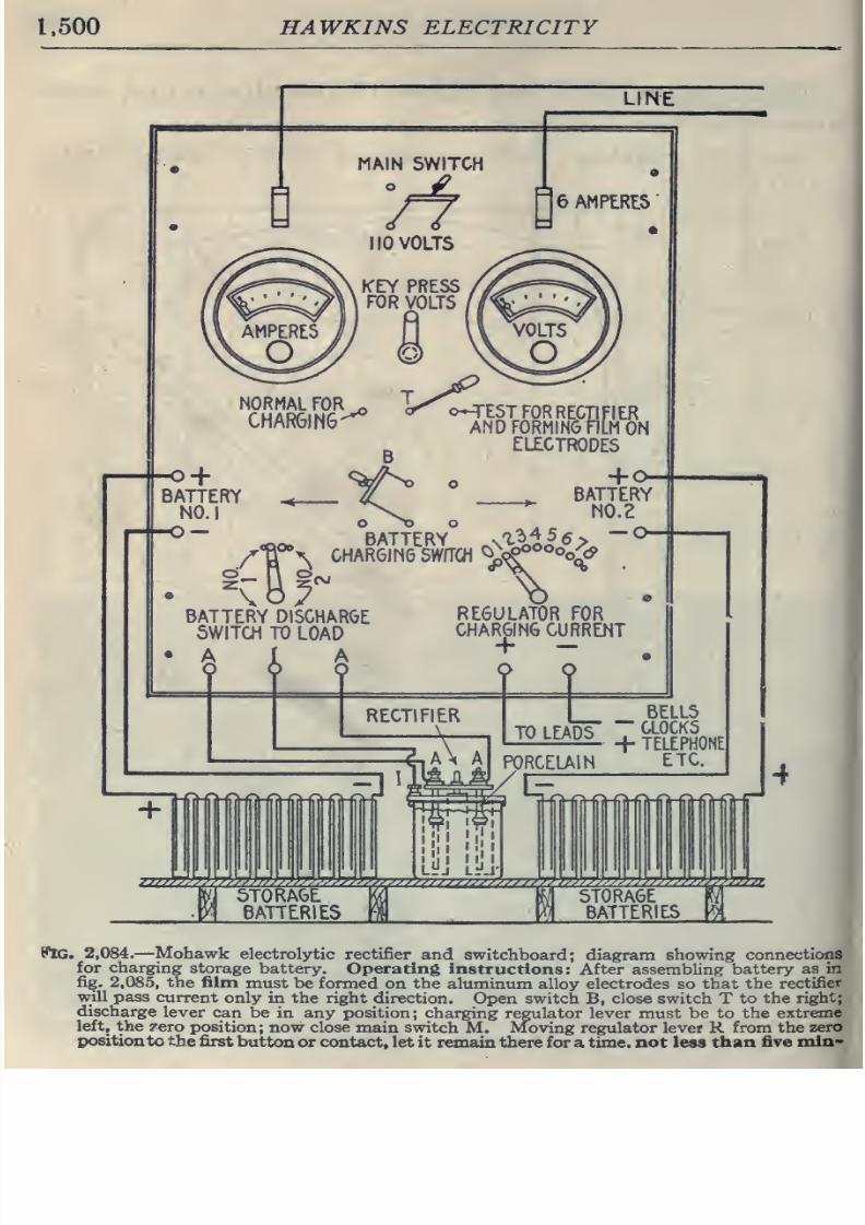
8/20/2019 electrical guide 5.pdf
http://slidepdf.com/reader/full/electrical-guide-5pdf 246/343
1.500
HAWKINS
ELECTRICITY
LINE
MAIN
SWITCH
t
/f
6 AMPERES
110
VOLTS
NORMAL
FOR
CHAR6IN6
o-TESTFORRECTIFIER
AND
FORMING
FILM
ON
ELECTRODES
^
BATTERY
O-
n^
BATTERY
^\^Al^^>
CHARGING
SWfTOI
^^^''o^
o
zzzzffl
9JG.
2,084.
—
Mohawk
electrolytic
rectifier
and
switchboard;
diagram showing
connections
for charging
storage battery.
Operating
instructions:
After assembling
battery
as
in
fig.
2,085,
the
film
must
be formed
on
the
aluminum alloy
electrodes
so
that the
rectifier
w;ill
pass
current
only in the right
direction.
Open
switch
B,
close
switch
T
to
the
right;
discharge
lever
can
be
in
any
position;
charging regulator
lever
must be
to the
extreme
left,
the
zero
position;
now
close
main switch
M.
Moving
regulator lever
R
from the
zero
position
tothe first
button
or
contact,
let
it
remain
there for
a
time, not less than
five
niin>
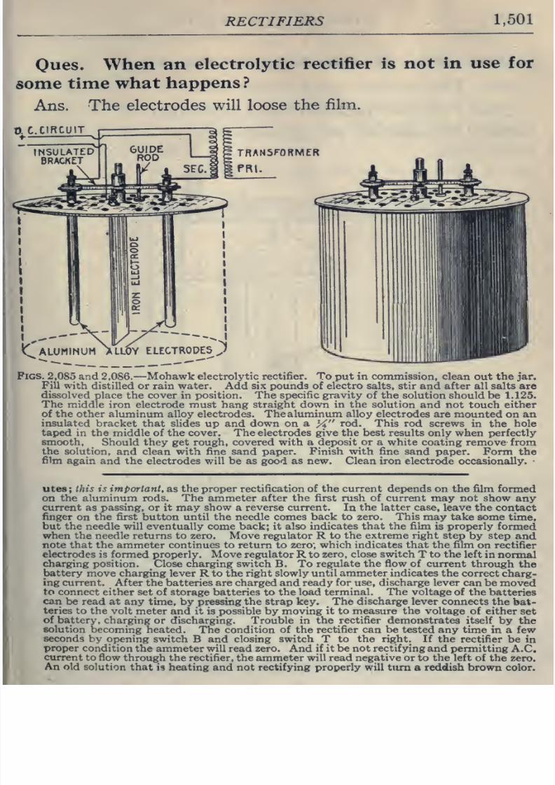
8/20/2019 electrical guide 5.pdf
http://slidepdf.com/reader/full/electrical-guide-5pdf 247/343
RECTIFIERS
1,501
Oues.
When an
electrolytic
rectifier
is
not
in
use
for
some
time
what
happens
?
Ans.
The
electrodes
will
loose
the
film.
TRANSFORMER
PRl.
Pigs.
2,085 and
2,086.
—Mohawk electrolytic rectifier. To put in
commission,
clean
out the
jar.
Fill
with
distilled
or
rain water.
Add
six
pounds
of
electro
salts,
stir
and
after
all
salts
are
dissolved
place
the cover
in
position. The
specific gravity
of
the
solution should
be 1.125.
The
middle iron electrode
must
hang straight
down in
the
solution and
not touch
either
of the
other
aluminum alloy electrodes.
The
aluminum alloy
electrodes are
mounted
on
an
insulated bracket
that
slides
up
and
down
on
a
X
rod. This
rod
screws
in
the
hole
taped
in
the
middle
of
the
cover.
The
electrodes
give
the
best
results
only
when
perfectly
smooth.
Should
they
get
rough, covered
with
a
deposit or
a
white
coating remove
from
the
solution,
and clean
with fine sand paper.
Finish
with
fine
sand paper.
Form
the
film
again
and
the
electrodes
will
be as
good
as
new. Clean iron electrode
occasionally.
utes; this
is
important,
as
the
proper rectification of
the
current
depends
on
the
film
formed
on
the
aluminum rods.
The
ammeter
after the
first
rush
of
current
may not
show
any
current as
passing,
or it may
show a reverse
current.
In
the latter case,
leave
the
contact
finger
on
the
first
button
until
the
needle comes
back
to
zero. This may take
some
time,
but the needle
will
eventually
come
back;
it
also indicates
that the film
is
properly
formed
when
the needle returns
to zero. Move
regulator
R
to
the
extreme
right
step
by
step
and
note
that
the ammeter continues to return
to
zero;
which indicates
that
the film
on rectifier
electrodes
is
formed properly. Move regulator
R
to
zero,
close
switch
T
to
the
left
in normal
charging
position. Close
charging
switch
B.
To
regulate the flow of
current
through
the
battery
move charging lever R to
the
right
slowly until
ammeter
indicates the
correct
charg-
ing
current.
After the batteries
are
charged
and ready
for use,
discharge
lever
can
be moved
to connect
either
set
of storage batteries
to
the load
terminal. The
voltage
of
the
batteries
can
be
read
at
any
time,
by
pressing
the
strap
key.
The
discharge
lever
connects
the bat-
teries
to the
volt
meter and
it is
possible by
moving
it
to
measure the
voltage
of
either
set
of battery,
charging
or discharging. Trouble in
the
rectifier demonstrates
itself
by
the
solution
becoming
heated.
The
condition
of the rectifier
can be tested
any time
in a
few
seconds
by
opening
switch
B and
closing
switch
T
to the right. If
the
rectifier be
in
proper
condition the
ammeter
will
read zero. And
if
it be
not
rectifying
and permitting
A.C.
current
to flow
through the
rectifier,
the
ammeter
will read negative or
to
the
left of the
zero.
An
old
solution
that is
heating
and
not
rectifying
properly
will
tiim
a
reddish brown
color.
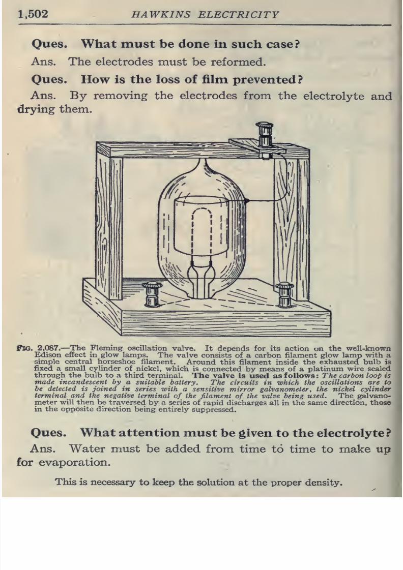
8/20/2019 electrical guide 5.pdf
http://slidepdf.com/reader/full/electrical-guide-5pdf 248/343
1,502
HAWKINS
ELECTRICITY
Ques.
What
must
be
done in
such
case?
Ans. The
electrodes
must be reformed.
Ones.
How is
the
loss
of
film
prevented
?
Ans.
By
removing
the
electrodes
from
the
electrolyte
and
drying
them.
Pig.
2,087.
—
The
Fleming
oscillation
valve.
It
depends
for
its
action
on
the
well-known
Edison effect in
glow lamps.
The
valve
consists
of a carbon
filament glow
lamp
with a
simple
central
horseshoe
filament.
Around this
filament
inside
the
exhausted
bulb
is
fixed
a
small
cylinder
of
nickel,
which is
connected
by means
of
a
platinum
wire
sealed
through
the
bulb
to a
third
terminal.
The valve is
used as
follows :
The
carbon
loop is
made
incandescent
by a
suitable
battery.
The
circuits
in
which
the
oscillations
are
to
be
detected
is
joined
in
series with a
sensitive
mirror
galvanometer,
the
nickel cylinder
terminal
and
the negative
terminal
of
the
filament
of
the
valve
being
used.
The
galvano-
meter
will then be
traversed
by a
series
of
rapid
discharges all
in
the same
direction, those
in
the opposite direction
being entirely
suppressed.
Ques.
What
attention
must
be
given
to
the
electrolyte
?
Ans.
Water
must
be added
from
time
to time
to
make up
for
evaporation.
This is necessary
to keep the solution
at
the proper
density.
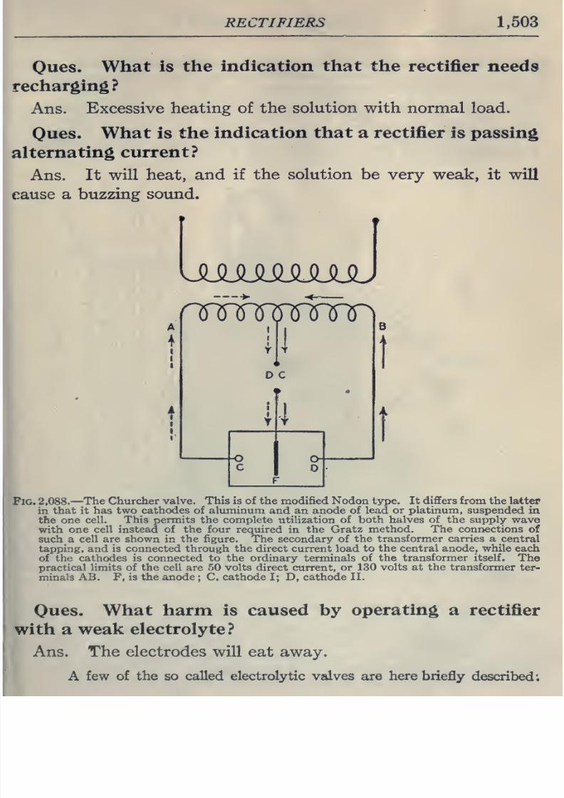
8/20/2019 electrical guide 5.pdf
http://slidepdf.com/reader/full/electrical-guide-5pdf 249/343
RECTIFIERS
1,503
Ques.
What
is
the
indication
that
the rectifier needs
recharging?
Ans.
Excessive
heating of
the
solution
with normal
load.
Oues.
What
is
the
indication
that
a
rectifier
is passing
alternating
current?
Ans.
It
will
heat, and
if
the solution
be
very weak,
it
will
cause a
buzzing
sound.
ulqjimmmJ
cruT^yuTr\
o
c
Fig.
2,088.
—
The
Churcher
valve. This
is
of
the
modified
Nodon type. It
differs
from
the
latter
in
that
it
has
two cathodes of
aluminum
and an
anode of
lead or platinum,
suspended in
the one
cell.
This
permits
the
complete
utilization
of both halves of the
supply
wave
with one
cell instead of
the
four
required
in
the Gratz
method.
The
connections
of
such
a
cell are
shown
in
the figure. The
secondary of
the
transformer carries a
central
tapping,
and
is
connected through the direct
current
load
to
the central anode, while
each
of the
cathodes
is connected to
the
ordinary terminals
of the
transformer
itself.
The
practical limits of the
cell
are 50
volts
direct
current, or
130
volts at the
transformer
ter-
minals AB. F,
is
the anode
;
C,
cathode
I;
D, cathode
II.
Oues.
What
harm
is
caused
by
operating
a
rectifier
with a
weak
electrolyte?
Ans.
The electrodes
will eat
away.
A
few
of
the
so called electrolytic
valves
are
here briefly
described;
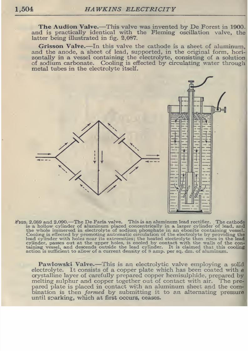
8/20/2019 electrical guide 5.pdf
http://slidepdf.com/reader/full/electrical-guide-5pdf 250/343
1,504
HAWKINS
ELECTRICITY
The
Audion
Valve.
—
This
valve
was
invented
by
De
Forest in
1900-
and
is
practically identical with
the
Fleming
oscillation
valve,
the
latter
being
illustrated
in
fig.
2,087.
Grisson
Valve.—In this
valve the
cathode
is
a
sheet
of
aluminum,
and
the
anode,
a
sheet
of
lead,
supported,
in
the
original
form,
hori-
zontally
in
a
vessel
containing
the
electrolyte,
consisting
of
a
solution
of
sodium carbonate.
Cooling
is
effected
by
circulating
water
through
metal
tubes
in
the
electrolyte itself.
thcs.
2,089
and
2,090.
—
The
De
Faria valve.
This is
an
aluminum
lead
rectifier.
The
cathod©'
is
a
hollow cylinder
of
aluminum
placed
concentrically
in a
larger
cylinder
of
lead,
and*
the
whole immersed
in
electrolyte
of
sodium phosphate
in an
ebonite
containing
vessel.
.
Cooling is
effected by promoting
automatic
circulation
of the
electrolyte
by
providing
the
lead
cylinder
with
holes
near its extremities;
the
heated electrolyte
then rises
in
the
lead
cylinder, passes
out at
the
upper
holes,
is
cooled by
contact with
the
walls of
the
con-
taining
vessel,
and
descends
outside the
lead
cylinder. It
is
claimed
that
this
cooling
action
is sufficient
to
allow
of a
current density
of
8
amp.
per
sq.
dm.
of
aluminum.
Pawlowski Valve.
—
This
is
an
electrolytic
valve employing
a
solid
electrolyte.
It consists of
a
copper plate which has
been
coated
with
a
crystalline
layer
of
carefully prepared copper hemisulphide,
prepared
by
melting
sulphur
and
copper
together
out
of
contact
with
air.
The pre-
pared
plate is placed
in
contact
with an
aluminum
sheet
and the
com-
bination
is
then
formed
by
submitting
it
to an alternating
pressure
until
sr»arking, which at
first occurs,
ceases.
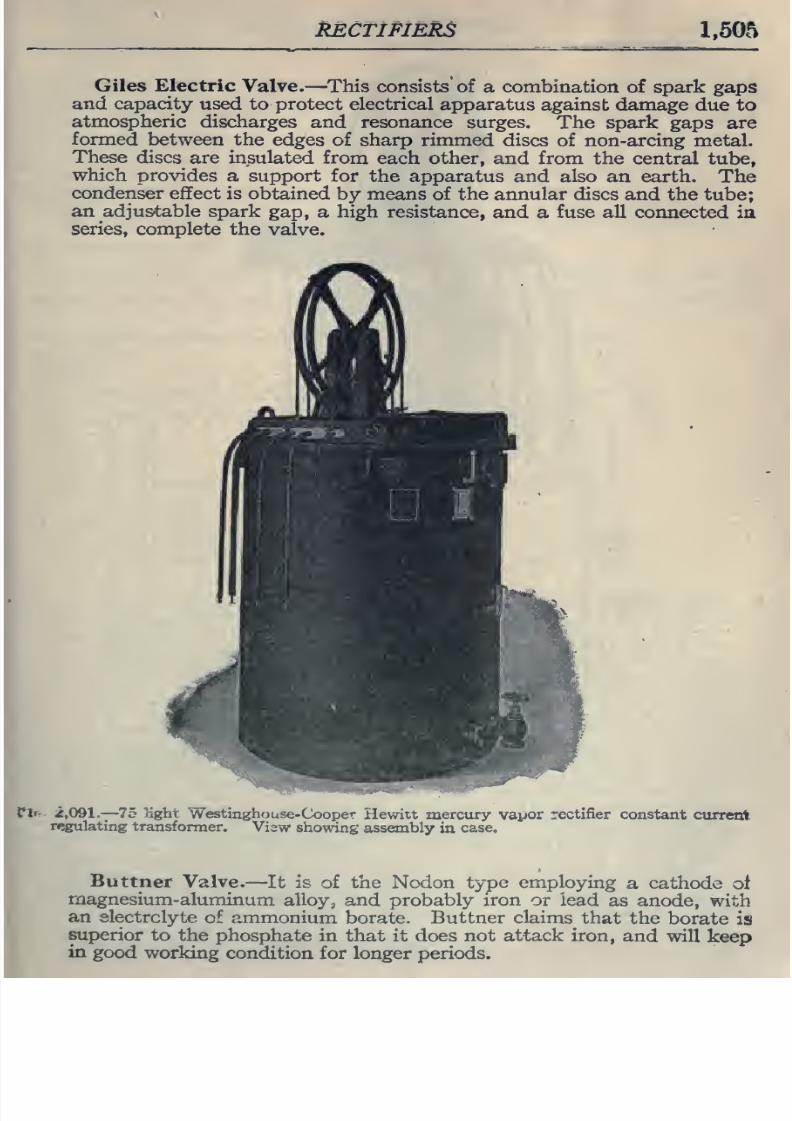
8/20/2019 electrical guide 5.pdf
http://slidepdf.com/reader/full/electrical-guide-5pdf 251/343
MCTIFIERS
1,505
Giles Electric
Valve.
—
This
consists'
of
a
combination of spark
gaps
and
capacity
used to
protect
electrical
apparatus
against
damage
due
to
atmospheric
discharges
and resonance
surges.
The spark
gaps
are
formed
between
the
edges
of
sharp
rimmed
discs of non-arcing
metal.
These
discs are
insulated
from
each
other,
and
from
the
central tube,
which
provides
a
support
for
the
apparatus
and also
an
earth.
The
condenser effect
is obtained
by
means of the annular
discs and
the tube;
an adjustable spark
gap,
a
high resistance,
and
a
fuse
all
connected ia
series,
complete
the
valve.
rir-
2,091.
—
75
light
Westinghouse-Cooper
Hewitt
mercury
vapor
rectifier
constant
current
regulating
transformer.
View
showing assembly
in
case.
Buttner
Valve.
—
It
is
of
the
Nodon
type employing
a cathode
of
magnesium-aluminum
alloy,
and
probably
iron or
lead
as anode,
with
an
electrolyte
of ammonium
borate. Buttner
claims
that the
borate
is
superior
to
the
phosphate in
that it does
not attack iron,
and
will
keep
in
good
working
condition
for
longer periods.
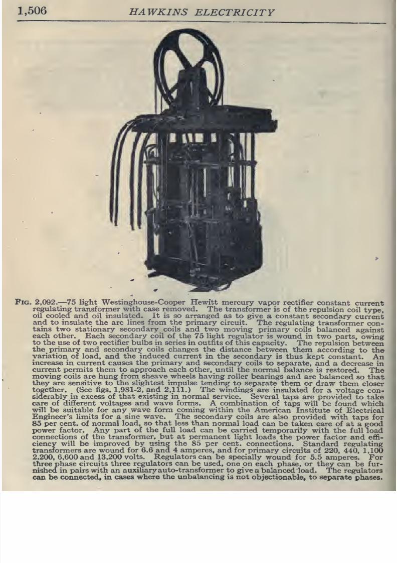
8/20/2019 electrical guide 5.pdf
http://slidepdf.com/reader/full/electrical-guide-5pdf 252/343
1,506
HAWKINS
ELECTRICITY
Pig. 2,092.-75
light
Westinghouse-Cooper
Hewitt
mercury
vapor rectifier
constant
current
regulating
transformer
with case removed.
The
transformer
is of the
repulsion
coil
type,
oil
cooled
and oil
insulated.
It
is
so arranged
as
to give
a
constant
secondary
current
and
to
insulate
the arc
lines
from
the primary
circuit.
The regulating
transformer
con-
tains
two stationary
secondary
coils and two
moving
primary
coils
balanced
against
each other.
Each
secondary
coil of the
75
light
regulator
is wound
in two
parts,
owing
to the use
of
two
rectifier
bulbs
in
series
in
outfits
of
this
capacity.
The
repulsion
between
the primary
and
secondary coils
changes
the
distance
between
them
according
to
the
variation
of
load,
and
the
induced current
in the
secondary
is
thus
kept
constant.
An
increase
in
current causes
the primary
and
secondary
coils
to separate,
and a
decrease
in
current permits
them to
approach each
other,
until the
normal
balance
is
restored.
The
moving coils are hung
from sheave wheels
having
roller
bearings
and are
balanced
so that
they are sensitive to
the slightest
impulse tending
to
separate
them
or
draw them
closer
together.
^
(See figs.
1,981-2,
and
2,111.)
The
windings
are
insulated
for
a
voltage
con-
siderably
in excess
of that
existing
in normal
service.
Several
taps
are
provided
to
take
care of
different voltages and wave
forms.
A
combination
of
taps
will
be found
which
will
be
suitable
for
any
wave
form
coming
within the
American
Institute
of
Electrical
Engineer's limits for
a
sine
wave. The
secondary
coils
are also
provided with
taps
for
85
per
cent,
of
normal
load, so
that
less
than
normal
load
can
be taken care of
at a good
power
factor.
Any
part
of
the
full
load
can be
carried
temporarily
with
the
full
load
connections
of
the
transformer,
but
at
permanent
light
loads
the
power
factor
and effi-
ciency
will
be
improved
by
using the
85 per
cent,
connections.
Standard regulating
transformers are wound
for 6.6 and
4
amperes,
and
for
primary
circuits of
220,
440,
1
, 100
2,200,
6,600
and
13,200
volts.
Regulators can
be specially
wound
for 5.5 amperes.
For
three
phase circuits
three
regulators
can
be
used, one
on each phase,
or they
can be
fur-
nished
in pairs with an
auxiliary
auto-transformer to
give
a balanced load. The
regulators
can.
be connected,
in
cases
where
the unbalancing
is not
objectionable,
to
separate
phases.
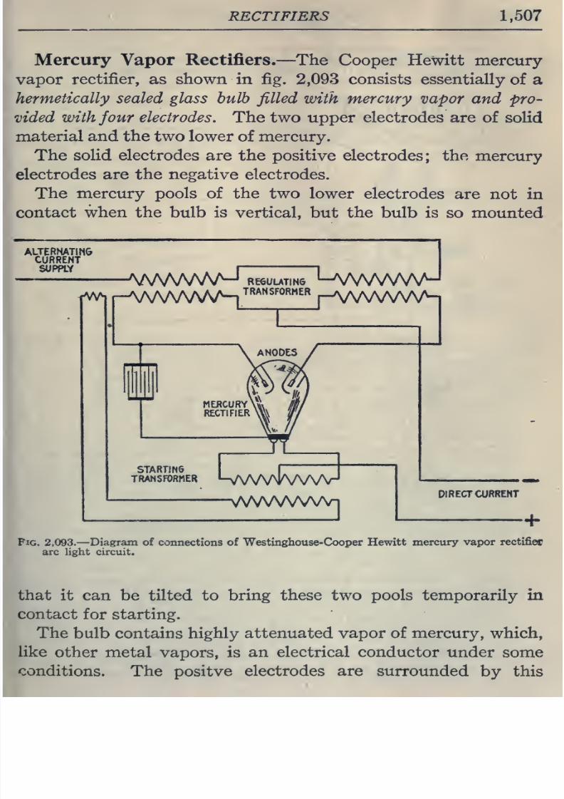
8/20/2019 electrical guide 5.pdf
http://slidepdf.com/reader/full/electrical-guide-5pdf 253/343
RECTIFIERS
1,507
Mercury
Vapor
Rectifiers.
—
The
Cooper
Hewitt
mercury
vapor
rectifier,
as
shown
in fig.
2,093
consists
essentially
of
a
hermetically
sealed
glass
bulb
filled
with
mercury
vapor and
pro-
vided
with
four
electrodes.
The
two
upper
electrodes
are
of
solid
material
and the
two lower
of
mercury.
The solid electrodes
are
the
positive
electrodes;
the
mercury
electrodes
are
the negative
electrodes.
The
mercury pools
of
the
two lower
electrodes
are
not
in
contact
when
the bulb
is
vertical,
but
the
bulb is
so
mounted
Fig. 2,093.
—
Diagram of
connections
of Westinghouse-Cooper Hewitt
mercury
vapor rectifies
arc
light
circuit.
that
it can
be
tilted
to
bring
these two
pools temporarily
in
contact
for
starting.
The
bulb contains
highly
attenuated vapor of mercury,
which,
like
other
metal
vapors, is
an
electrical
conductor
under
some
conditions.
The
positve
electrodes
are surrounded
by this
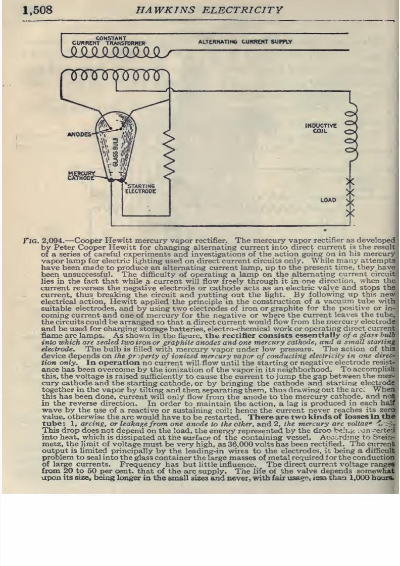
8/20/2019 electrical guide 5.pdf
http://slidepdf.com/reader/full/electrical-guide-5pdf 254/343
1,508
HAWKINS
ELECTRICITY
I
CONSTANT
CURRENT
TRANSFORMER
ALTERNATING
CURREHT SUPPLY
INOOCTfVE
COJL
flG.
2,094.
—
Cooper
Hewitt mercury
vapor
rectifier.
The
mercury vapor
rectifier as developed
by
Peter
Cooper
Hewitt
for changing alternating
current
into
direct
current is
the
result
CI a
series of careful experiments
and
investigations of
the
action
going
on in
his
mercury
vapor
lamp
for electric
lighting
used
on
direct current
circuits only.
While
many
attempts
have
been
made
to
produce
an alternating
current lamp, up
to
the
present
time,
they
have
been
unsuccessful.
The
difficulty
of
operating a lamp on the
alternating
current
circuit
lies
in the fact
that
while
a
current
will flow freely through
it in
one
direction,
when
the
current
reverses
the
negative electrode
or
cathode
acts
as
an electric
valve and
stops the
current,
thus breaking
the
circuit
and
putting
out the
light.
By
following
up this new
electrical
action,
Hewitt
applied
the
principle
in
the
construction of
a
vacuuni tube witli
suitable
electrodes,
and
by
using two electrodes of
iron or
graphite
for
the
positive
or
in-
coming
current
and one
of mercury
for
the negative
or
where
the
current
leaves the tube,
the
circuits could
be arranged
so
that
a
direct current
would
flow
from
the
rnercury electrode
and
be
used
for charging
storage batteries,
electro-chemical
work or
operating
direct
current
flame
arc lamps.
As shown
in the figure, the
rectifier
consists
essentially
of
a glass
bulb
into
which
are
sealed
two iron
or
graphite
anodes
and
one
mercury
cathode,
and
a
small
starting
electrode. The
bulb
is
filled with
mercury vapor under
low
pressure.
The
action
of
this
device
depends
on
the
property
of
ionized
mercury vapor
of
conducting
electricity
in one
direc-
tion
only. In operation
no
current
will
flow
until the
starting
or
negative
electrode
resist-
ance
has
been
overcome
by
the ionization
of the vapor in
its
neighborhood.
To
accomplish
this, the
voltage
is
raised
sufficiently
to cause
the
current
to
jump
the
gap
between
the
mer-
cury
cathode
and
the starting
cathode,
or
by
bringing
the
cathode
and
starting
electrode
together
in
the
vapor
by
tilting
and
then separating
them,
thus
drawing out
the
arc.
When
this
has been
done,
current
will only flow
from
the
anode to
the
mercury
cathode,
and not
in
the
reverse
direction.
In
order
to
maintain
the
action, a
lag
is
produced
in each
half
wave
by the
use
of
a reactive
or sustaining
coil;
hence the
current
never
reaches
its
zero
value, otherwise
the arc
would have
to
be
restarted.
There
are two
kinds of
losses in
the
tube:
1,
arcing,
or leakage
from
one
anode
to
the
other, and 2,
the
mercury
arc
voltag'
-^i
:;•-.
This
drop
does
not
depend on
the
load,
the
energy
represented
by
the
droc
beii.^.
:
on
v-e.cted
into
heat, which
is
dissipated
at the
surface
of the
containing
vessel.
Acc::.rd:ng to
Srein-
metz,
the
limit
of
voltage must
be
very
high, as
36,000
volts
has
been
rectified.
The
current
output
is limited
principally
by
the
leading-in wires to
the
electrodes,
it
being a
difficult
problem
to seal into
the
glass
container the
large
masses
of
metal required
for the conduction.
of
large currents.
Frequency has
but
little
influence. The
direct
current voltage
ranges
from 20
to 50
per
cent, that of
the
arc
supply.
The
life of the
valve depends
somewhat
upon
its size,
being
longer
in the
small
sizes
and
never,
with
fair
usa^e,
less
than
1,000
hours.
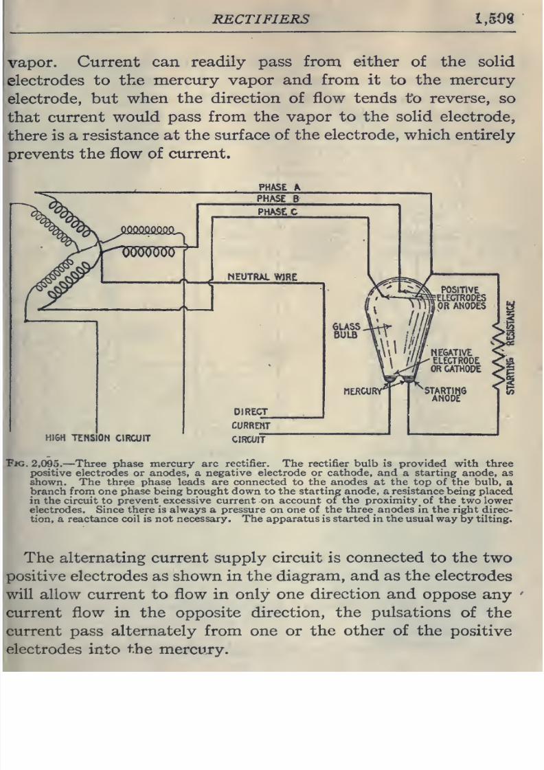
8/20/2019 electrical guide 5.pdf
http://slidepdf.com/reader/full/electrical-guide-5pdf 255/343
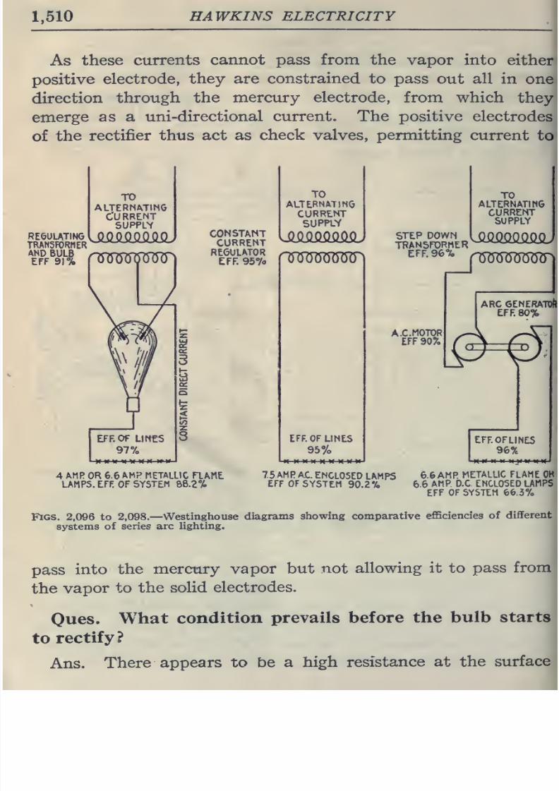
8/20/2019 electrical guide 5.pdf
http://slidepdf.com/reader/full/electrical-guide-5pdf 256/343
1,510
HAWKINS ELECTRICITY
As
these
currents
cannot
pass from
the vapor
into
either
positive
electrode, they
are
constrained
to
pass
out
all in
one
direction
through
the
mercury electrode,
from
which
they
emerge
as
a
uni-directional current.
The
positive
electrodes
of
the
rectifier
thus act as
check
valves,
permitting
current
to
TO
alternating
Current
SUPPLV
constant
CURRENT
REGULATOR
EFF.
957o
TO
ALTERNATING
CURRENT
SUPPLY
J?.O.Q.Q.Q.QM
rWOOTOW
EFF.
OF
LINES
95%
STEP DOWN
TRANSFORMER
EFF.
96%
TO
ALTERNATING
CURRENT
SUPPLY
wo'croow
A.
C.
MOTOR
EFF
90%
ARC GENERATOR,
EFF
80%
\&=0\
EFFOFLINES
96%
4
AMR
OR 6.6
AMP
METALLIC
FIAME
UMP5.
EFF
OF
SYSTEM 88.2%
75
AMP
AC.
ENCLOSED
LAMPS
EFF OF
SYSTEM
90.2%
6.6AMR
METALLIC FLAME OK
6.6
AMP
D.C
ENCLOSED
LAMPS
EFF
OF
SYSTEM
66.3%
Figs.
2,096
to
2,098.—
Westinghouse
diagrams
showing comparative
efficiencies
of
different
systems
of
series
arc
lighting.
pass
into
the
mercury
vapor
but
not
allowing
it to
pass
from
the
vapor
to
the
solid
electrodes.
Oues.
What
condition
prevails before
the
bulb
starts
to
rectify?
Ans.
There
appears to be
a
high
resistance
at the
surface
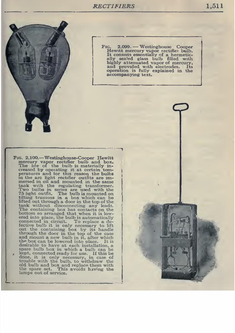
8/20/2019 electrical guide 5.pdf
http://slidepdf.com/reader/full/electrical-guide-5pdf 257/343
RECTIFIERS
1,511
Fig.
2,099.
—
Westinghouse
Cooper
Hewitt mercury
vapor
rectifiet
bulb.
It
consists
essentially
of
a
hermetic-
ally
sealed
glass
bulb filled
with
highly
attenuated
vapor
of
mercury,
and
provided with
electrodes.
Its
operation
is fully
explained
in
the
accompanying
text.
Pig. 2,100.—
Westinghouse-Cooper Hewitt
mercury
vapor
rectifier
bulb and box.
The
hfe
or the bulb
is
materially
in-
creased
by
operating
it at
certain
tem-
peratures
and for this
reason the
bulbs
m
the
arc
light rectifier
outfits
are
im-
mersed
in
oil
and mounted
in
the
same
tank
with the
regulating
transformer.
Two
bulbs
in
series
are
used
with
the
75
light outfit.
The
bulb is mounted
on
tilting
trunions
in
a
box which
can be
lifted
out
through
a
door
in
the
top
of
the
tank
without
disconnecting
any
leads.
The
containing
box has
contacts
on
the
bottom
so
arranged
that
when it
is
low-
ered
into place,
the
bulb is
automatically
connected
in
circuit.
To
replace
a
de-
fective
bulb
it is
only
necessary to
lift
out
the
containing
box
by
its handle
through
the
door
in
the
top
of the
case
and
mount
a new
bulb
in
it,
after which
thf»
box
can
be
lowered
into
place.
It
is
desirable
to have
at
each installation,
a
spare
bulb
box
in which
a
bulb can
be
f
kept,
connected ready
for
use.
_
If
this
be
done,
it is
only necessary,
in case of
trouble
with
the
bulb,
to
withdraw the
old
bulb
and
box
and replace
them with
the
spare
set.
This avoids
having
the
lamps
out
of
service.
o
8/20/2019 electrical guide 5.pdf
http://slidepdf.com/reader/full/electrical-guide-5pdf 258/343
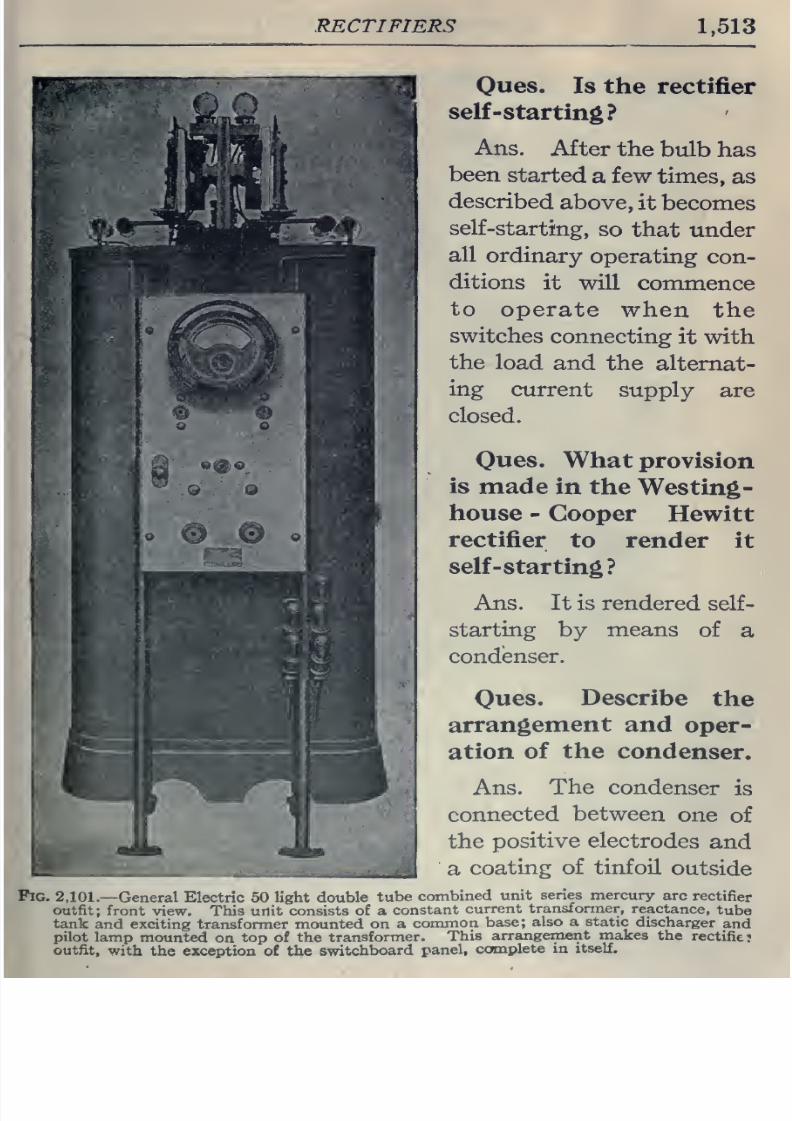
8/20/2019 electrical guide 5.pdf
http://slidepdf.com/reader/full/electrical-guide-5pdf 259/343
RECTIFIERS
1,513
Fig
Ques.
Is the
rectifier
self
-starting?
Ans.
After
the
bulb
has
been
started
a few
times,
as
described
above,
it becomes
self-starting,
so
that
under
all
ordinary
operating
con-
ditions
it
will
commence
to
operate
when
the
switches
connecting
it
with
the
load
and
the
alternat-
ing
current
supply
are
closed.
Oues.
What
provision
is
made
in
the
Westing
house
-
Cooper
Hewitt
rectifier
to
render
it
self
-star
ting?
Ans.
It
is
rendered
self-
starting
by
means
of
a
condenser.
Ques.
Describe
the
arrangement
and
oper-
ation
of
the
condenser.
Ans.
The
condenser
is
connected
between
one
of
the
positive
electrodes
and
a
coating
of tinfoil
outside
2,101.—
General
Electric 50
light double
tube
combined
unit
series mercury
arc
rectifier
outfit;
front
view.
This
unit consists
of a
constant
current
transformer,
reactance,
tube
tank
and
exciting transformer
mounted
on
a
common
base;
also a static
discharger
and
pilot
lamp
mounted
on
top of the
transformer.
This
arrangement
makes
the
rectifies
outfit,
with
the
exception
of
the
switchboard
panel,
complete
in
itself.
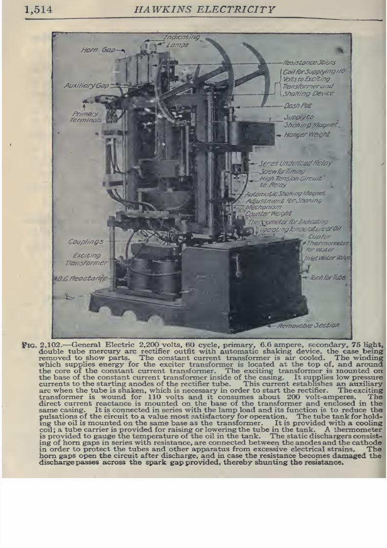
8/20/2019 electrical guide 5.pdf
http://slidepdf.com/reader/full/electrical-guide-5pdf 260/343
1,514
HAWKINS
ELECTRICITY
Horn
6ap
Aux///oryGap
'.
Jnd/cat/ng
ffes/sto/7CeJtyc/rs
Co//rorJapp/y//7g//0
\to/i3
to
Exciting
Transformersnd
5ha/r/ng
De\'/ce
—
Do3hPot
JuppiyCo
5fja/iing
Magrjet,
y*-
Monger
WeirM
-5enes
Under/oacfffe/ay
-JaenforT/'mim
_H/g/>
Tens/on
Circuit
'
to
ffe/ay
I
Auto/r/aCicS/fo/nng
Magnet
Adjtistmer/t
forJ/?a
/ring
:Mec/ ai7/s/n
iCoL/PterWe/g/)t
''
Tiier^omelerforM/cot/np
~\r
^Operat/ngJe/vperaiareaO//
^-
'^
'
-
'
Cop
for
\j^Tiiermometer
for
Water
XlnietWoterValve
TanAforTute
Femoifob/e
Jection
iPlG.
2,102.—
General
Electric
2,200 volts,
60
cycle,
pnmary, 6.0
ampere,
secondary,
75 light,
double
tube mercury
arc
rectifier
outfit
with automatic
shaking
device,
the
case
being
removed
to show
parts.
The constant current
transformer
is air
cooled. The winding
which
supplies energy for the
exciter
transformer is located
at
the
top
of,
and around
the
core of
the constant
current transformer.
The
exciting
transformer
is
mounted
on
the
base
of the constant
current
transformer
inside of
the
casing.
It
supplies low
pressure
currents
to the
starting
anodes of
the
rectifier
tube.
This current
establishes
an auxiliary
arc
when
the tube
is
shaken,
which is necessary
in
order
to
start the
rectifier.
The
exciting
transformer is wound
for
110 volts and it consumes
about 200
volt-amperes,
^
The
direct
current
reactance
is
mounted
on
the
base
of
the
transformer
and
enclosed
in
the
same
casing.
It is connected
in
series with
the
lamp
load
and its function
is
to reduce the
pulsations
of
the
circuit
to
a
value
most
patisfactory
for
operation.
The
tube
tank
for
hold-
ing
the oil is mounted
on
the
same
base as the transformer.
It
is
provided
with
a cooling
coil
; a
tube
carrier
is provided
for
raising or lowering
the
tube
in the
tank.
A
thermometer
is
provided
to
gauge
the
temperature
of
the
oil
in
the tank.
The
static
dischargers consist-
ing
of
horn
gaps in
series
with resistance,
are
connected
between the anodes
and
the
cathode
in
order
to
protect
the
tubes
and other
apparatus
from
excessive electrical
strains.
The
horn
gaps
open
the
circuit
after
discharge, and
in
case the
resistance
becomes
damaged
the
discharge
passes across
the
spark
gap
provided,
thereby shunting the resistance.
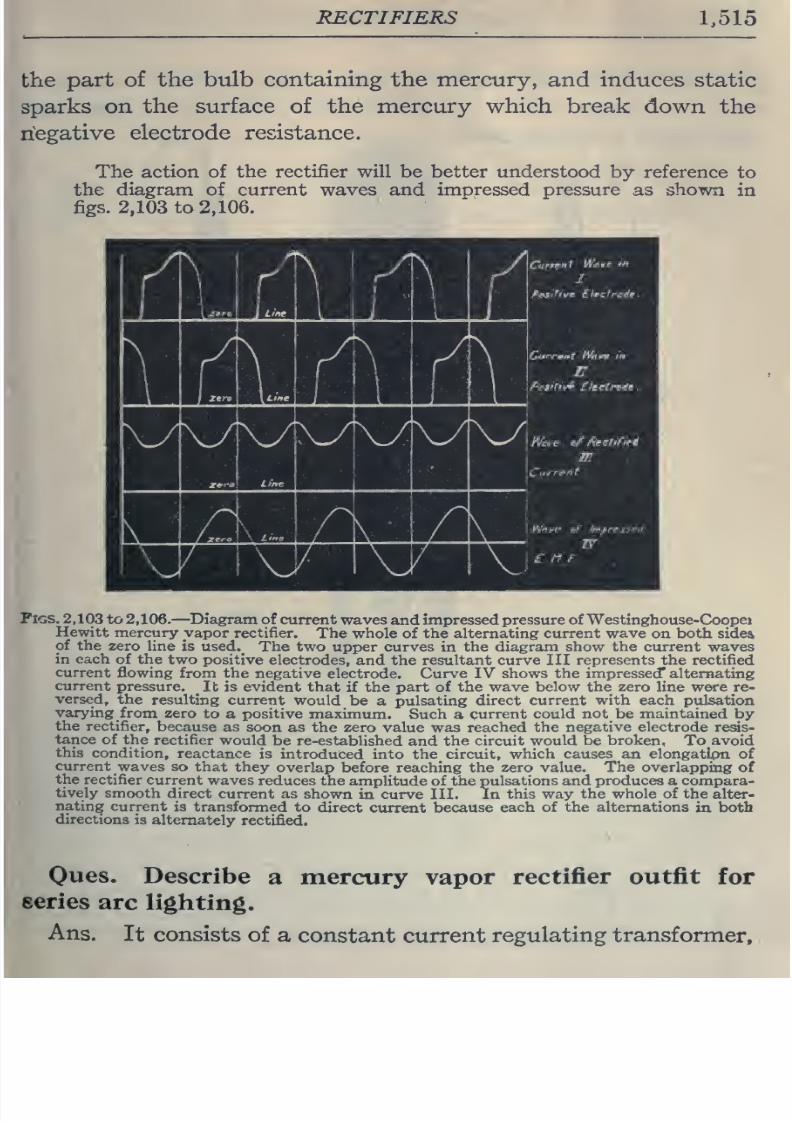
8/20/2019 electrical guide 5.pdf
http://slidepdf.com/reader/full/electrical-guide-5pdf 261/343
RECTIFIERS
1,515
the
part of
the
bulb
containing
the mercury,
and
induces
static
sparks
on
the surface
of
the mercury which
break
down
the
negative
electrode resistance.
The
action
of
the
rectifier
will
be
better
understood
by
reference
to
the
diagram of current
waves
and impressed
pressure
as
shown
in
figs.
2,103
to
2,106.
v/vy
Figs.
2,103 to
2,106.
—
Diagram
of
current
waves
and
impressed pressure ofWestinghouse-Coopet
Hewitt
mercury yapor
rectifier.
The
whole
of
the
alternating
current
wave
on
both
sidea
of the
zero
line
is used._
The two
upper curves
in
the diagram show
the
current waves
in
each
of the
two
positive
electrodes,
and
the
resultant
curve
III
represents
the
rectified
current
flowing
from
the
negative
electrode. Curve IV
shows the impressed* alternating
current
pressure.
It
is
evident that
if
the part
of
the
wave
below
the
zero
line
were
re-
versed,
the resulting
current
would
be
a
pulsating direct
current
with each
pulsation
varying
from
zero
to a positive
maximum.
Such
a
current
could not be maintained
by
the
rectifier,
because
as
soon
as
the zero value was
reached
the negative
electrode
resis-
tance
of
the
rectifier
would
be
re-established
and
the
circuit
would be
broken.
To avoid
this
condition,
reactance
is introduced
into the
circuit,
which
causes an
elongatifm of
current
waves so
that they
overlap
before
reaching the
zero value. The overlapping
of
the
rectifier
current
waves
reduces the
amplitude
of
the
pulsations
and
produces a compara-
tively
smooth
direct
current as
shown
in curve
III.
In
this way
the whole of
the
alter-
nating
current
is
transformed
to
direct
current
because each
of
the alternations
in both
directions
is
alternately
rectified.
Oues.
Describe
a
mercury
vapor
rectifier
outfit
for
series
arc
lighting.
Ans.
It
consists
of
a
constant
current
regulating transformer.
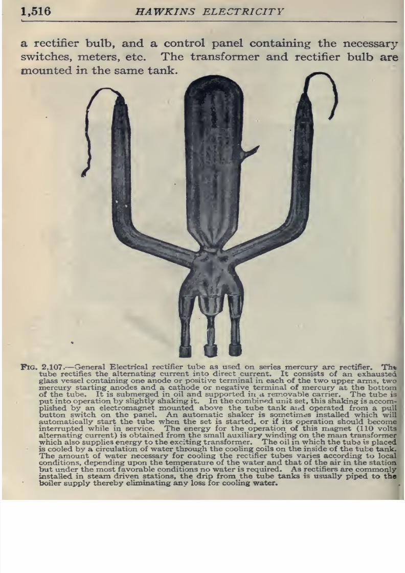
8/20/2019 electrical guide 5.pdf
http://slidepdf.com/reader/full/electrical-guide-5pdf 262/343
1,516
HAWKINS ELECTRICITY
SL
rectifier
bulb, and
a
control panel
containing
the necessary-
switches,
meters, etc.
The
transformer
and rectifier
bulb
are
mounted
in the
same
tank.
Pig.
2,107.
—
General
Electrical
rectifier tube
as
used
on
series mercury
arc
rectifier.
Th*
tube
rectifies
the
alternating
current into direct
current. It consists
of
an exhausted
glass
vessel containing one
anode
or
positive terminal
in
each of
the
two
upper
arms, two
mercury
starting anodes
and
a
cathode or
negative
terminal
of
mercury
at
the
bottom
of
the
tube. It
is
submerged
in
oil
and
supported
in
a
removable
carrier.
The
tube
is
put into
operation
by
slightly
shaking
it. In
the
combined unit set, this
shaking
is accom-
plished
by
an
electromagnet
mounted
above
the
tube
tank
and
operated
from
a
pull
button
switch on
the
panel.
An
automatic shaker
is
sometimes
installed
which will
automatically start the
tube
when
the set
is started, or if its
operation
should
become
interrupted
while
in
service.
The
energy for the operation
of
this
magnet
(110 volts
alternating current)
is
obtained
from
the small
auxiliary
winding
on
the
mam
transformer
which also
supplies energy to
the
exciting
transformer.
The
oil in
which
the
tube is
placed
is cooled
by
a
circulation
of water through
the cooling
coils
on
the inside of the
tube
tank.
The
amount
of water
necessary for
cooling
the
rectifier tubes
varies
according to
local
conditions,
depending upon
the
temperature
of
the
waterand that
of
the
air
in
the
station
but
under the
most favorable
conditions
no water is required. As
rectifiers
are
commonly
installed
in
steam
driven
stations,
the
drip
from
the tube
tanks
is
usually
pii)ed
to
the
boiler supply
thereby
eliminating any
loss
for
cooling
water.
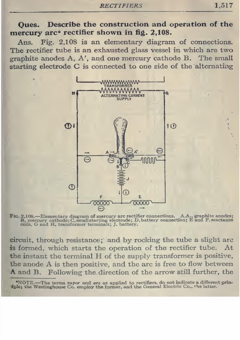
8/20/2019 electrical guide 5.pdf
http://slidepdf.com/reader/full/electrical-guide-5pdf 263/343
RECTIFIERS
1,517
Ques.
Describe
the
construction
and
operation
of
the
mercury
arc=^
rectifier
shown
in
fig.
2,108.
Ans.
Fig.
2,108
is an
elementary
diagram
of
connections.
The
rectifier
tube
is
an
exhausted
glass vessel in
which
are
two
graphite
anodes A,
A', and one
mercury cathode
B.
The
small
starting
electrode
C is
connected to
one
side
of
the
alternating
H
®i
Q)
-^mmmmtw—
TRANSFORMER
ALTERNATING
CURRENT
SUPPLY
-=-J
e
E
t0
Fig.
2,108.
—Elementary diagram
of
mercury arc
rectifier
connections.
A,A.,
graphite
anodes;
B,
mercury
cathode
; C.
small
starting electrode;
D, battery
connection;
E
and
F.i^actance
coils,
G and
H, transformer terminals;
J.
battery.
circuit,
through resistance; and
by
rocking
the
tube a
slight
arc
is
formed,
which
starts
the
operation
of
the
rectifier tube. At
the
instant
the
terminal
H
of
the
supply
transformer
is
positive,
the
anode
A
is
then
positive,
and
the arc
is
free
to
flow
between
A
and
B.
Following
the.
direction of
the
arrow
still
further,
the
•NOTE.
—
The terms
vapor
and arc as
applied to
rectifiers,
do
not
indicate
a
different
prin-
dple;
the
Westinghouse
Co. employ the
former,
and the
General
Electric
Co..
the
latter.
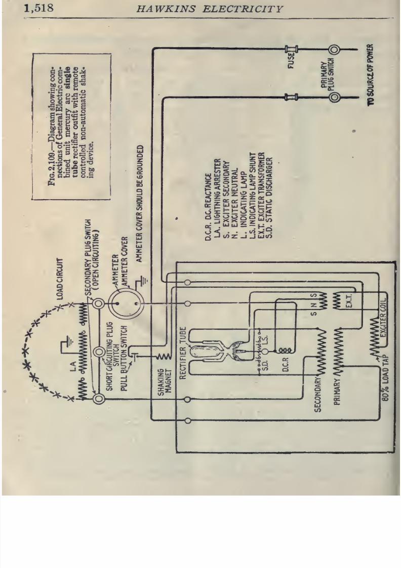
8/20/2019 electrical guide 5.pdf
http://slidepdf.com/reader/full/electrical-guide-5pdf 264/343
1.518
HAWKINS
ELECTRICITY
h^SBJi
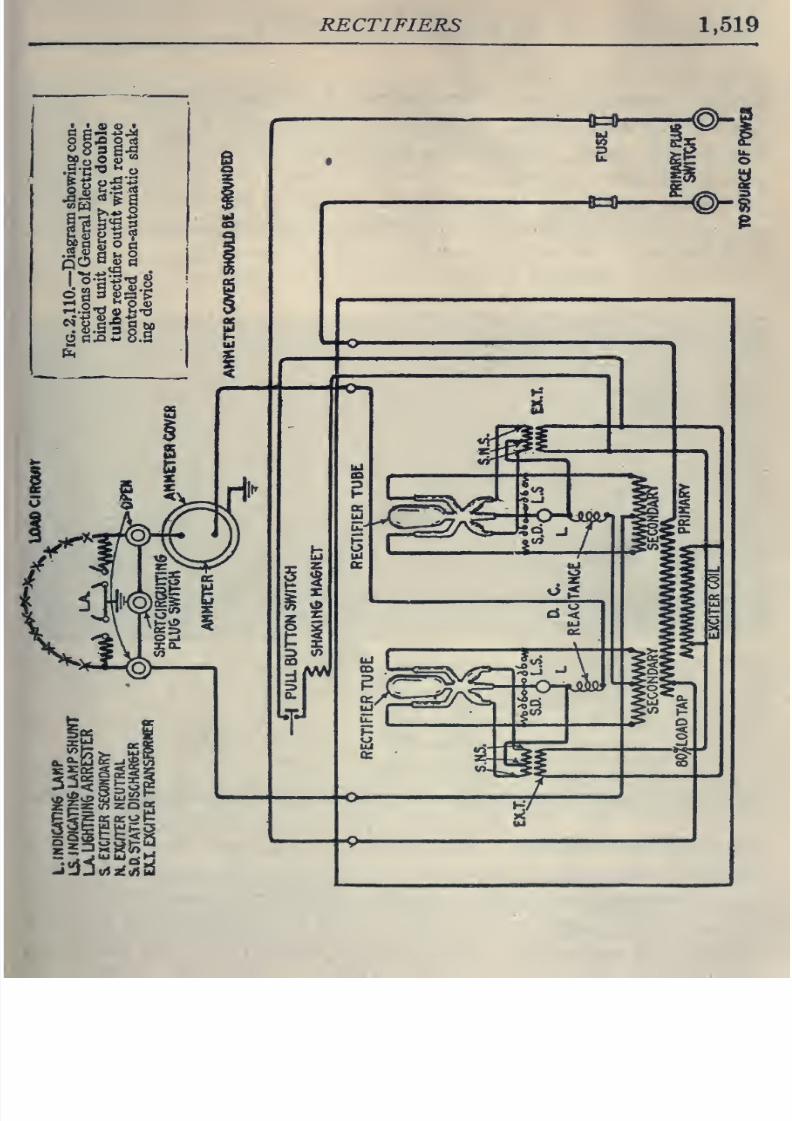
8/20/2019 electrical guide 5.pdf
http://slidepdf.com/reader/full/electrical-guide-5pdf 265/343
RECTIFIERS
1,519
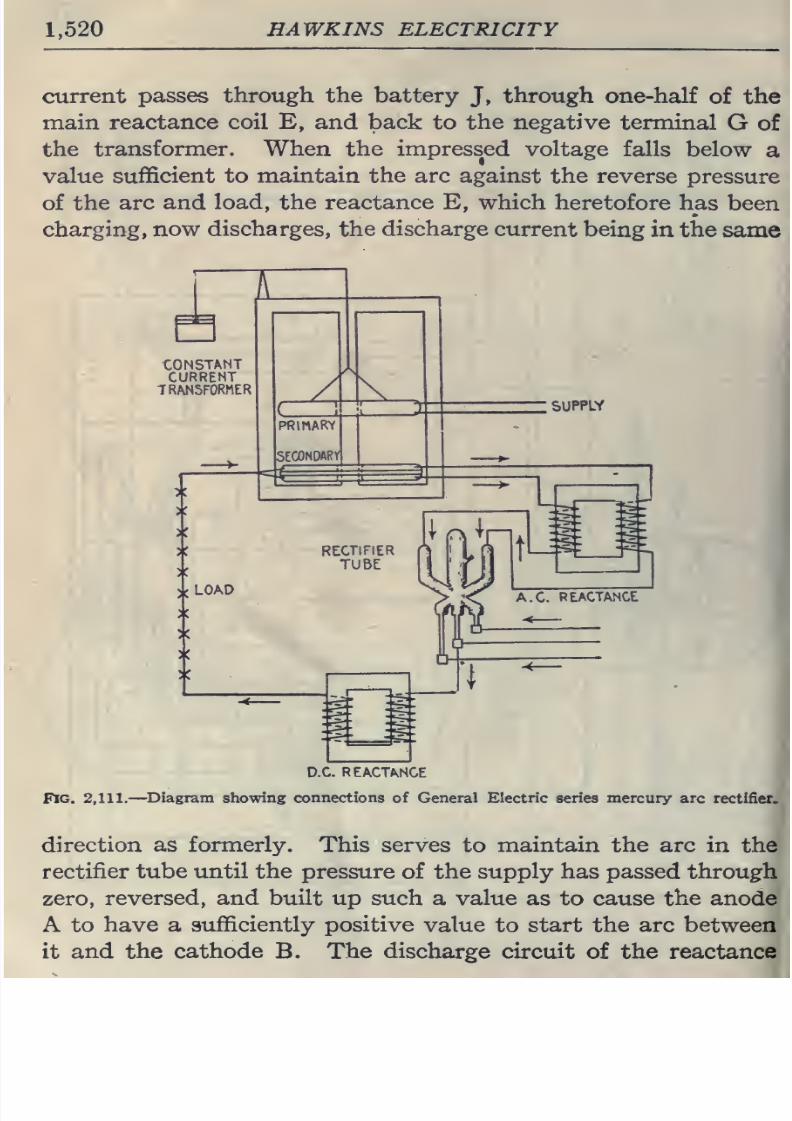
8/20/2019 electrical guide 5.pdf
http://slidepdf.com/reader/full/electrical-guide-5pdf 266/343
1,520
HAWKINS ELECTRICITY
current
passes
through
the battery
J,
through
one-half
of the
main
reactance
coil E,
and back
to
the negative
terminal
G
of
the
transformer. When the impressed
voltage
falls
below
a
value
sufficient
to
maintain
the arc
against
the reverse
pressure
of
the
arc
and
load,
the
reactance E,
which
heretofore
has
been
charging,
now
discharges,
the
discharge
current
being
in
the
same
D.C.
REACTANCE
Fig.
2,111.
—
Diagram
showing
connections
of
General
Electric
series
mercury
arc
rectifier.
direction
as formerly.
This serves
to
maintain
the arc
in
the
rectifier
tube until
the
pressure
of
the
supply
has
passed
through
zero,
reversed, and built
up such
a
value
as to
cause
the anode
A to
have a sufficiently positive
value
to
start the arc
between
it and the
cathode
B. The
discharge
circuit
of
the
reactance
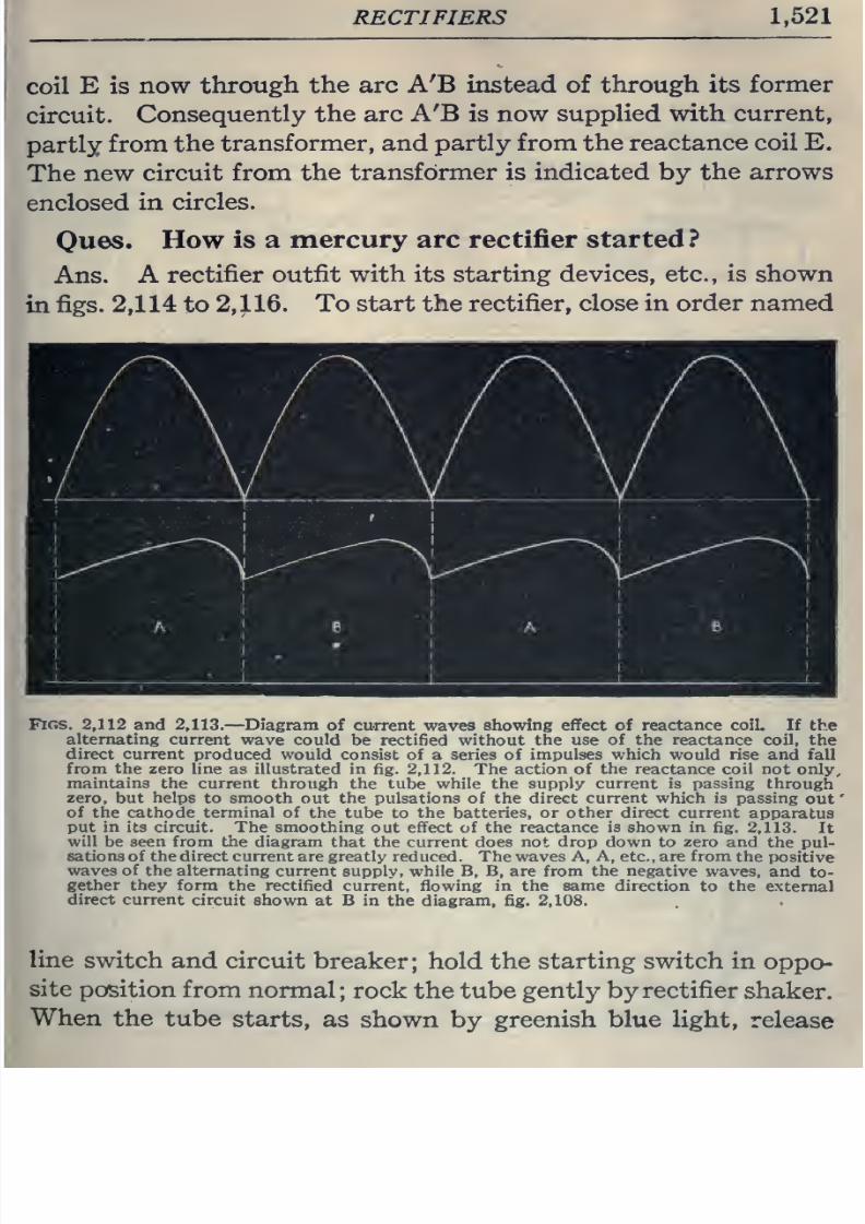
8/20/2019 electrical guide 5.pdf
http://slidepdf.com/reader/full/electrical-guide-5pdf 267/343
RECTIFIERS
1,521
coil
E
is
now
through
the arc
A'B instead
of
through
its
former
circuit.
Consequently
the
arc
A'B
is
now
supplied with
current,
partly
from
the
transformer,
and
partly
from
the reactance
coil E.
The
new
circuit
from
the
transformer is indicated by
the
arrows
enclosed
in
circles.
\
Ques.
How
is
a
mercury
arc rectifier started
?
Ans.
A
rectifier
outfit with its starting
devices, etc., is shown
in
figs. 2,114 to
2,
116. To start the
rectifier, close in
order named
Figs.
2,112
and
2,113.
—Diagram
of
current
waves
showing effect of reactance coil. If
the
alternating
current
wave could
be
rectified
without
the
use
of
the
reactance coil,
the
direct current
produced
would
consist
of a
series
of
impulses
which would
rise and
fall
from
the
zero
line
as
illustrated
in
fig. 2,112.
The
action
of
the
reactance coil
not
only,
maintains the
current
through
the tube
while
the
supply current is passing
through
zero,
but
helps
to smooth
out
the pulsations of the direct current which is passing
out
of the cathode terminal
of
the
tube
to
the batteries, or
other direct
current
apparatus
put
in
its
circuit.
The
smoothing
out
effect
of
the reactance
is
shown in
fig.
2,113.
It
will
be
seen from
the diagram
that the
current
does
not drop
down
to zero and
the
pul-
sations
of
the direct current
are greatly reduced. The waves
A, A,
etc.,
are
from
the
positive
waves
of
the
alternating
current supply,
while
B, B, are
from the
negative waves,
and
to-
gether they form
the
rectified
current,
flowing
in
the
same direction
to
the
external
direct current
circuit
shown
at B in
the
diagram,
fig.
2,108.
line
switch
and
circuit
breaker;
hold the starting
switch
in
oppo-
site
position
from
normal
;
rock
the
tube
gently
by
rectifier
shaker.
When the
tube
starts,
as
shown
by
greenish blue
light,
release
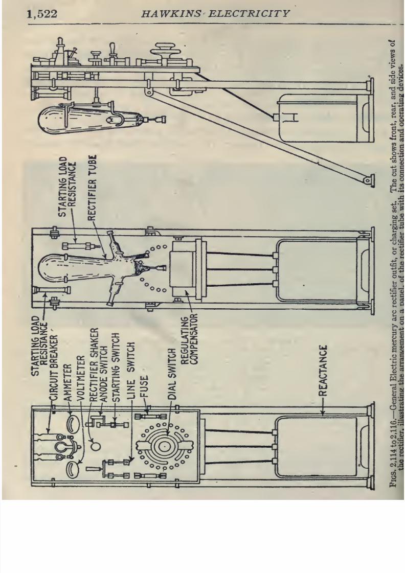
8/20/2019 electrical guide 5.pdf
http://slidepdf.com/reader/full/electrical-guide-5pdf 268/343
1,522
HAWKINS
ELECTRICITY
.^J^^h^
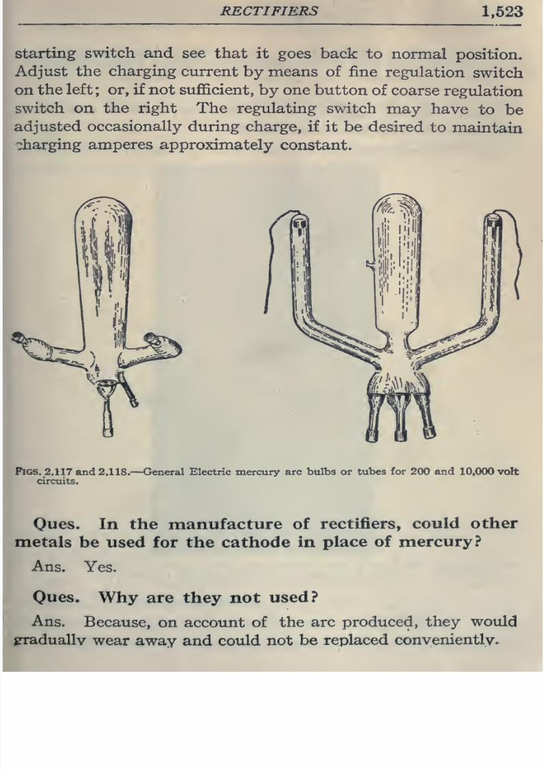
8/20/2019 electrical guide 5.pdf
http://slidepdf.com/reader/full/electrical-guide-5pdf 269/343
RECTIFIERS
1,523
starting
switch and
see
that
it goes back
to
normal
position.
Adjust the
charging
current
by
means
of
fine
regulation
switch
on
the
left
;
or, if not
sufficient,
by
one
button
of
coarse
regulation
switch
on
the
right
The
regulating
switch
may
have
to
be
adjusted
occasionally
during
charge,
if
it
be
desired
to
maintain
^^harging amperes
approximately
constant.
Pigs.
2,117
and
2,118.
—
General
Electric
mercury
arc
bulbs
or
tubes
for
200
and
10,000
volt
circuits.
Oues.
In
the manufacture of
rectifiers,
could other
metals
be used
for
the cathode
in
place
of mercury?
Ans.
Yes.
Oues. Why
are
they
not
used?
Ans.
Because,
on
account
of
the
arc
produced,
they
would
jpraduallv
wear
away
and could
not
be
replaced
conveniently.
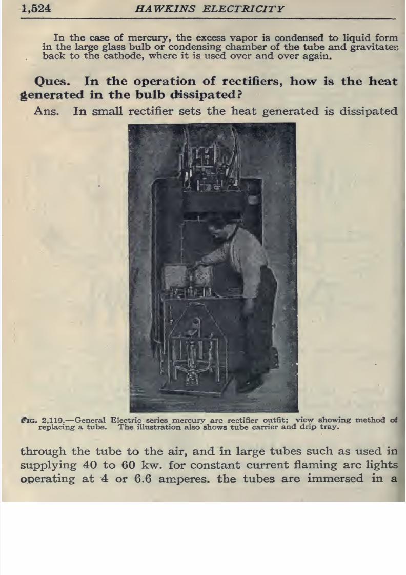
8/20/2019 electrical guide 5.pdf
http://slidepdf.com/reader/full/electrical-guide-5pdf 270/343
1,524
HAWKINS ELECTRICITY
In
the
case
of
mercury,
the
excess
vapor
is
condensed
to
liquid
form
in the large glass bulb or
condensing chamber
of the
tube
and gravitaten
back
to
the
cathode,
where it is
used over
and
over again,
Oues.
In
the
operation
of rectifiers,
how is the
heat
generated
in the bulb
dissipated?
Ans.
In
small
rectifier
sets
the heat generated
is
dissipated
ftc.
2,119.
—
General
Electric series mercury
arc
rectifier
outfit;
view
showing
method
of
replacing a
tube.
The illustration
also
shows
tube
carrier
and
drip tray.
through
the
tube
to
the
air,
and
in large
tubes
such as
used in
supplying
40
to
60
kw.
for
constant
current
flaming
arc
lights
operating at
4
or
6.6
amperes,
the
tubes
are immersed
in
a
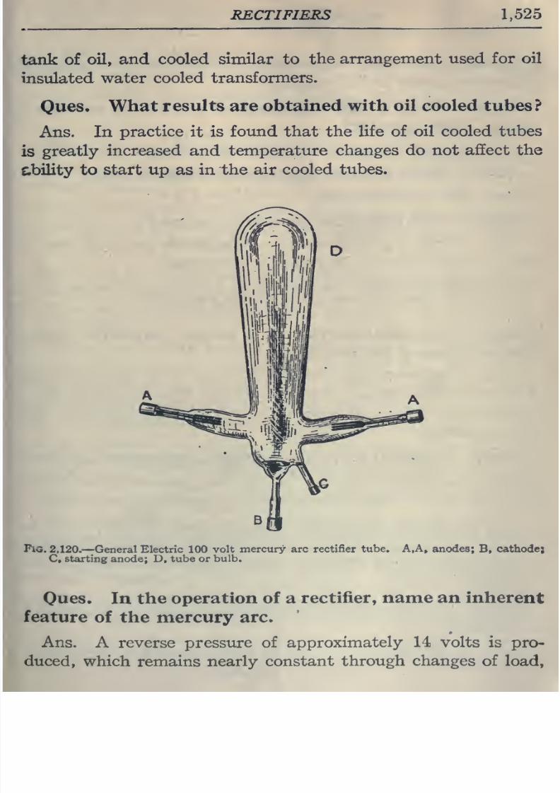
8/20/2019 electrical guide 5.pdf
http://slidepdf.com/reader/full/electrical-guide-5pdf 271/343
RECTIFIERS
1,525
tank
of
oil, and
cooled
similar
to
the
arrangement used for
oil
insulated
water
cooled
transformers.
Ques.
What
results
are
obtained
with
oil
cooled tubes?
Ans.
In
practice
it
is
found
that the
life
of
oil cooled
tubes
is
greatly
increased and temperature
changes
do
not
affect
the
ability
to start
up
as
in
the air
cooled
tubes.
Pig.
2,120.
—
General
Electric 100
volt
mercury arc
rectifier
tube.
A,A, anodes;
B,
cathodej
C,
starting anode; D,
tube
or
bulb.
Ques.
In
the
operation
of
a
rectifier,
name
an
inherent
feature
of
the
mercury
arc.
Ans.
A reverse pressure
of
approximately
14
volts
is
pro-
duced,
which
remains nearly
constant
through
changes
of
load,
8/20/2019 electrical guide 5.pdf
http://slidepdf.com/reader/full/electrical-guide-5pdf 272/343
1,526
HAWKINS
ELECTRICITY
frequency,
and
voltage.
Its
effect
is
to decrease
the
commercial
efficiency
slightly
on
light
loads.
Ones.
What
is the
advantage
of
a
rectifier
set over
a
motor
generator
set?
Ans. Higher
efficiency and
lower
first
cost.
Ques.
What is
the capacity
of
a
rectifier
tube?
Ans.
40
to
50 amperes.
Oues.
How
is
greater
capacity
obtained?
Ans.
When
a
greater
ampere
capacity
is
reqtdred,
two
or
more
rectifier
sets
can
be joined
to
one circuit.
The
rectifier
may
be
joined in series
for
producing an increased
voltage
or
two
tubes
can be
connected
in
series
in
a
single set.
Ques.
For
what
service is
a
rotary
converter
better
adapted than
a
rectifier?
Ans.
For
power
distribution
and
other
cases
where
a
great
amount
of
alternating
current is to be
converted
into
direct
current, the
rotary converter
or large motor generator sets
are
more
practical.
Ques.
For
what service
is
a
rectifier
especially
adapted?
Ans.
It
is
very
desirable
for
charging
storage
batteries
for
automobiles from
the local
alternating current lighting
circuit.
When
the consumer installs
and
operates
the apparatus for his
own
use
and
wear,
there
is
considerable
saving
over motor
generator
sets
because
a
small
one
to
two horse power motor generator outfit has an efficiency
of only
40
to 50
per
cent,
while
mercury
vapor
rectifiers
will
have
from
75
to 80 per cent.
Ones.
What
precautions
should
be taken
in
installing
a
rectifier?
Ans.
It
should
be
installed
in
a
dry
place
and
care
shotild
be
taken
to
avoid dangling
wires
near
the
tube
to prevent
8/20/2019 electrical guide 5.pdf
http://slidepdf.com/reader/full/electrical-guide-5pdf 273/343
RECTIFIERS
1,527
puncturing. If
the
apparatus
be
installed
in
a
room
of
uniform
moderate
temperature
very little
trouble
will
be
experienced
in
starting,
while
extreme cold will
make starting
more
difficult.
*Electro-inagnetic
Rectifiers.
—
Devices
of
this
class consist
essentially
of
a
double
contact
rocker
which
rocks
on
pivot
(midway
between
the contacts),
in synchronism with
the fre-
quency of
the
alternating
current,
so
changing
the connections
at the
instants
of
reversals
of
the
alternating
current that
a
direct
current is obtained.
Fig.
2,121
is
a combined
sketch
and
diagram
of connections
of
a
type
of
electro-magnetic
rectifier
that
has
been
introduced
for changing
alternating into
direct
current.
The
actual ap-
paratus
consists
of
a
box, with perforated
metal sides,
about
ten
inches
square and
six inches deep.
This
box contains the
step
down
transformer
P,S,S',
and the
condensers
K
and
K',
the magnets
and
contact
making
device
about to
be
described
being fixed
on
the
polished
slate
top of
the
box,
exactly
as
shown
in
the figure.
The
transformer primary
winding
P
may
be
connected
through
a
switch
5 with a pair
of
ways
on
the
nearest
distribution
box, or to a
plug connection
or
lamp-
holder,
and
the
apparatus
will
give
a
rectified
current
of
6 or
12
amperes
at 20 volts,
according to
the
size.
S and
S'
is the
secondary
winding of the
transformer,
with
a
tapping
t midway,
joining
it
to
a
series
circuit
containing
two
alternating
current
electro-magnets
E
and
E',
whose
cores
are connected
by
the
long
soft
iron
yoke
Y. Pivoted
at
P'
is
a
steel
bar
SB,
which
is
polarized
by
the
two
coils
C
and
C
the
current
being
supplied
by
a
cell
A.
Fixed
•NOTE..
—The Edison
electro-magnetic
rectifier
is
described
in
detail in
GinoB
No,
4.
liages
942
to 945.
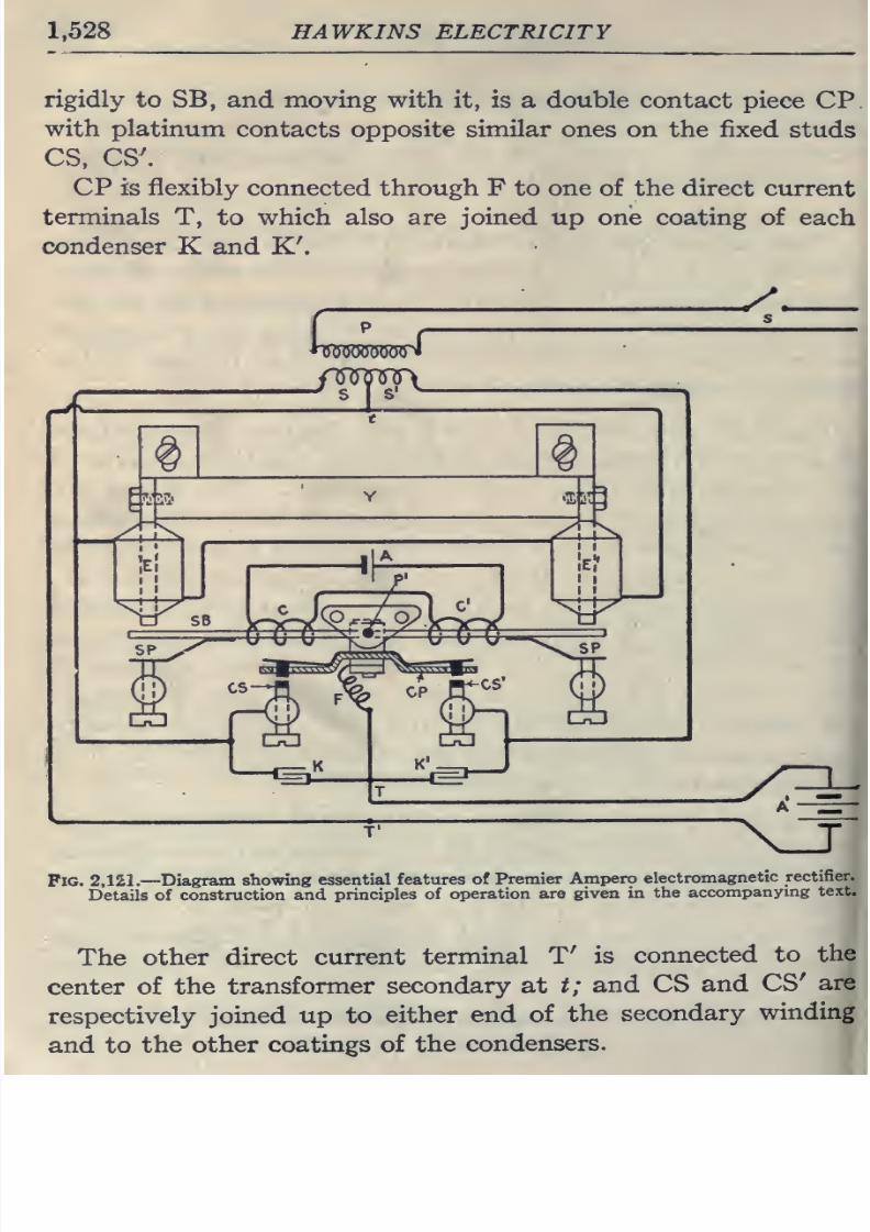
8/20/2019 electrical guide 5.pdf
http://slidepdf.com/reader/full/electrical-guide-5pdf 274/343
1,528
HAWKINS ELECTRICITY
rigidly
to
SB,
and moving with
it, is a
double
contact
piece
CP
with platinum
contacts opposite
similar
ones on
the fixed
studs
CS,
CS'.
CP
is
flexibly
connected
through
F
to
one
of
the
direct
current
terminals T,
to
which
also
are
joined
up one coating
of
each
condenser
K
and
K'.
r
f—
-jV—
^w
y.
z:^
Fig.
2,121.—
Diagram
showing
essential
features
of
Premier
Ampero
electromagnetic
rectifier.
Details
of
construction and
principles
of
operation
are given
in
the
accompanymg
text.
The
other
direct
current
terminal
T' is
connected
to
the
center
of
the
transformer
secondary at
t;
and CS
and
CS'
are
respectively
joined
up to
either
end
of
the
secondary
winding
and
to
the
other
coatings
of
the
condensers.
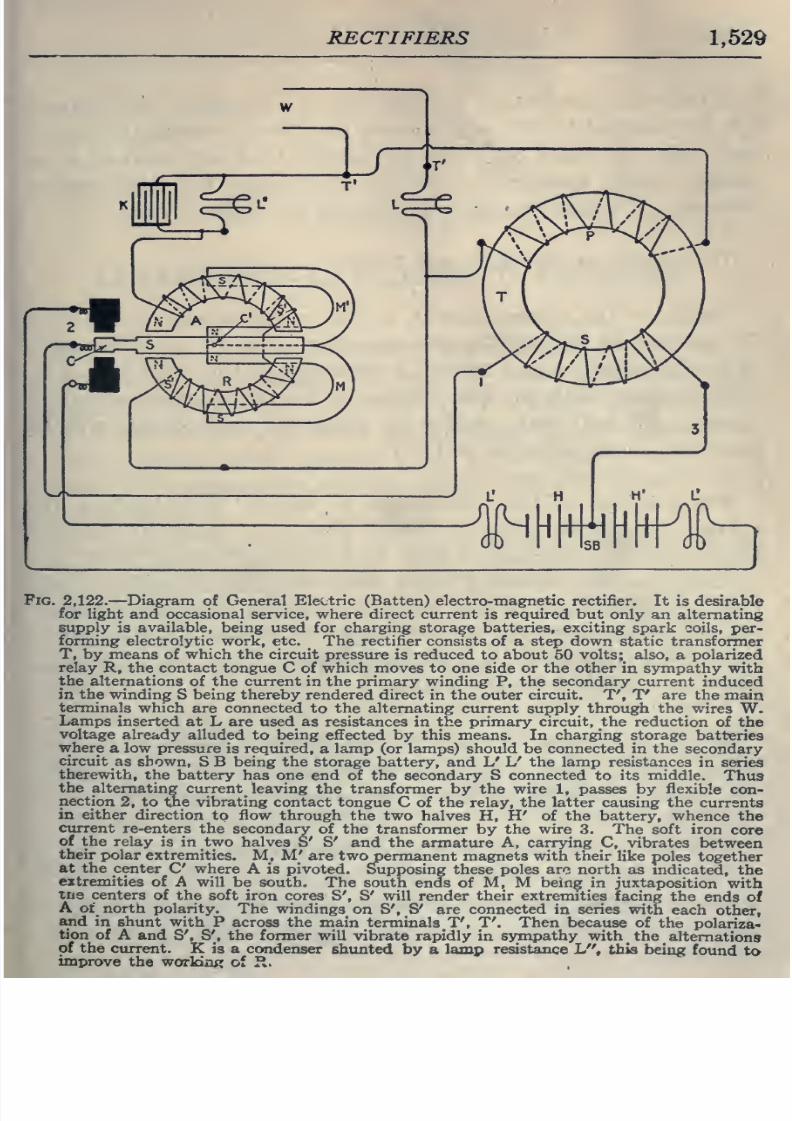
8/20/2019 electrical guide 5.pdf
http://slidepdf.com/reader/full/electrical-guide-5pdf 275/343
RECTIFIERS
1,529
Fig.
2,122.
—
Diagram
of
General
Eleetric
(Batten) electro-magnetic
rectifier.
It
is
desirable
for light and occasional service, where direct current
is
required
but
only an
alternating
supply
is
available, being used
for
charging storage
batteries,
exciting
spark coils,
per-
forming
electrolytic work,
etc.
The
rectifier
consists
of a
step
down
static transformer
T,
by
means
of
which
the
circuit
pressure
is
reduced
to about 50 volts; also,
a
polarized
relay
R,
the contact tongue
C
of which
moves to
one
side
or the other
in sympathy
with
the
alternations
of
the
current
in
the
primary
winding
P,
the
secondary
current
induced
in
the winding
S
being
thereby rendered direct
in the outer
circuit.
T', T' are the
main
terminals
which
are connected
to
the alternating
current
supply through
the
wires
W.
Lamps
inserted
at L are used as
resistances
in
the
primary circuit,
the reduction
of
the
voltage
already
alluded
to
being
effected by this means. In charging storage
batteries
where
a low
pressure
is
required,
a
lamp
(or
lamps)
should
be
connected
in the
secondary
circuit
as
shown,
S
B
being
the
storage
battery, and
L'
L'
the
lamp
resistances
in
series
therewith,
the
battery
has
one
end of the secondary
S
connected to its middle.
Thus
the alternating
current leaving
the transformer by the wire
1,
passes by
flexible
con-
nection
2,
to
the
vibrating
contact tongue
C of the relay,
the
latter
causing
the
currents
in
either direction
to
flow
through
the two
halves
H, H'
of
the
battery,
whence the
current
re-enters the
secondary
of the
transformer by
the wire 3. The
soft iron
core
of
the relay
is in two
halves
S'
S' and
the
armature
A,
carrying C,
vibrates
between
their
polar
extremities.
M,
M'
are
two
permanent magnets
with
their
like
poles
together
at
the
center
C
where
A
is
pivoted.
Supposing
these
poles am north
as
mdicated,
the
extremities
of
A
will
be south.
The
south
ends of
M,
M
being
in
juxtaposition
with
trie
centers
of
the
soft iron
cores
S', S'
will
render
their extremities
facing
the
ends
of
A of
north polarity.
The
windings
on S',
S'
are
connected
in
series
with
each
other,
and
in
shunt
with
P
across
the main
terminals
_T',
T'. Then because
of
the
polariza-
tion
of
A
and
S',
S',
the former
will
vibrate
rapidly in
sympathy with
the
alternations
of
the
current. K is
a
condenser
shunted
by
a
lamp
resistance L , this
being
found
to
improve
the woTkin«
of
H.
8/20/2019 electrical guide 5.pdf
http://slidepdf.com/reader/full/electrical-guide-5pdf 276/343
1,530
HAWKINS ELECTRICITY
When
the alternating
current
circuit
is
broken,
the springs
SP,
SP,
carried
by
SB and
bearing
against
the
adjustable
studs,
keep SB,
CS
and
CS'.
The apparatus
thus
acts also
as
a
no
voltage circuit
breaker,
for
should
the
supply
fail,
the
storage
battery
A' under
charge will
be left on
open
circuit.
The
action of the
device is
briefly
as follows:
Owing
to
the
direct
current
in
the
magnetizing
coils
C and
C
one
end
of
SB
will
be
permanently
of
north
and
the
other
of
south
polarity;
and since the polarities
of
the poles
E
and E'
will alternate with the
alternations
of the transformer
secondary
current, SB
will
rock rapidly
on
its
pivot,
and
contact
will
be
made
b\^
turns
with
CS
and
CS'.
The
purpose of
the condensers
K and
K'
is
to reduce
the
sparking at
these
points.
When
contact
is
made
at
CS, the
direct
current
terminals
T
and
T'
are
connected
to
the
S
half
of
the
secondary
winding;
and when contact
is
made at
CS',
they
are
connected
to the
S'
half.
Thus a
rectified
unidirec-
tional
current
will
flow
from
T
and
T',
and it
may be
used
to
charge
the
battery A',
work
a
small
motor
or
for
various
other
purposes
requiring
direct current.
When
the
rectifier
is
used
for charging
storage
batteries,
the
separate
cell
A
may
sometimes be dispensed with,
the
winding
C,C'
being
connected
to
one
of the
cells
under charge.
The
rectifier is
adjusted
to suit
the
frequency
of
the supply
circuit by
altering the
distance
of
the
poles
of
E
and
E'
from
the
ends
of
the polarized armature
SB;
and also by
changing
the
tension
of
SP, SP
by
means
of the
screw studs
against
which
they
bear.
8/20/2019 electrical guide 5.pdf
http://slidepdf.com/reader/full/electrical-guide-5pdf 277/343
ALTERNATING
CURRENT
SYSTEMS
1,531
CHAPTER
LV
ALTERNATING CURRENT
SYSTEMS
The
facility
with
which
alternating
current
can be
trans-
formed
from one
voltage
to
another, thus permitting
high
pressure
transmission
of
electric energy to
long
distances
through
small wires,
and low
pressure
distribution
for
the
operation of
lighting
systems and
motors,
gives a far
greater
variety
of
systems of
transmission
and
distribution
than
is
possible
with
direct
current.
Furthermore,
when
the
fact that
two
phase current can
be
readily
transformed
into
three phase
current, and these
con-
verted into
direct current,
and
vice
versa, by
means
of rotary
converters and
rectifiers,
is added
to
the advantages
derived
by
the use
of
high
tension
systems,
it is
apparent
that
the
opportunity
for
elaboration
becomes
almost
unlimited.
These
conditions
have
naturally tended
toward
the
development of
a
great
variety
of
systems,
employing
more or less
complicated
circuits
and
apparatus,
and
although
alternating
current
practice
is
still
much
less
definite
than direct
current
work,
certain
polyphase
systems
are now being
generally
accepted
as repre-
senting
the
highest
standards
of
power
generation,
transmission
and
distribution.
A classification
of
the
various
alternating
current systems,
to
be
comprehensive,
should
be
made
according to several
points
of view,
as
follows:
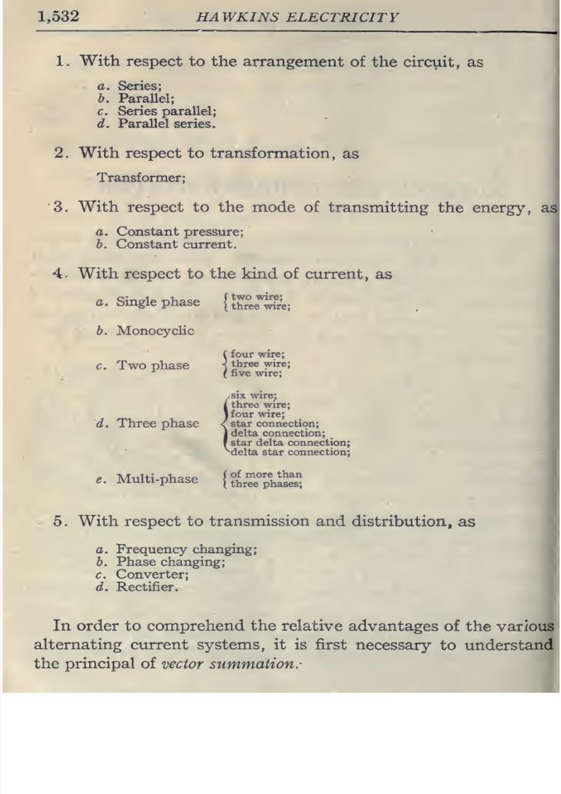
8/20/2019 electrical guide 5.pdf
http://slidepdf.com/reader/full/electrical-guide-5pdf 278/343
1,532
HAWKINS
ELECTRICITY
1. With respect to
the arrangement
of
the
circuit,
as
a. Series;
b.
Parallel;
c. Series
parallel;
d. Parallel series.
2. With respect to
transformation,
as
Transformer;
3.
With
respect
to
the
mode of
transmitting
the
energy,
as
a. Constant
pressure;
b.
Constant
current.
4<
With respect
to
the kind
of
current,
as
a.
Single
phase
{S°et&.
b. Monocyclic
(
four
wire;
C.
Two
phase
-^
three
wire;
•^
(
five wire;
,six
wire;
i
three
vvire;
I four
wire;
d.
Three phase
/
star
connection;
1 delta connection;
f
star
delta
connection;
^
delta star
connection;
..
Multi-phase
{l?e%hS?s^
5.
With respect to
transmission
and
distribution,
as
a.
Frequency
changing;
b. Phase
changing;
c.
Converter;
d.
Rectifier.
In order to comprehend
the
relative
advantages
of
the
various
alternating current
systems,
it
is first
necessary
to
understand
the
principal of
vector summation.-
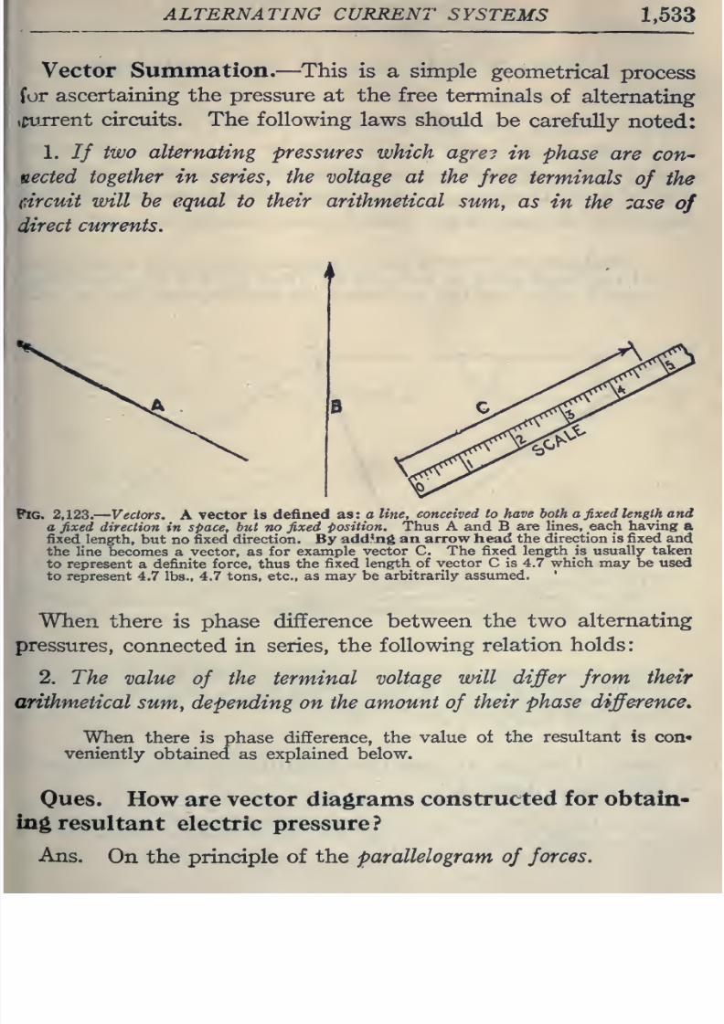
8/20/2019 electrical guide 5.pdf
http://slidepdf.com/reader/full/electrical-guide-5pdf 279/343
ALTERNATING
CURRENT
SYSTEMS
1,533
Vector
Summation.—
This
is a simple
geometrical
process
for
ascertaining
the
pressure
at
the
free
terminals
of
alternating
tCurrent
circuits.
The following
laws
should
be
carefully
noted:
1.
// two
alternating
pressures
which
agre?
in
phase
are
con--
uected
together in serieSy
the
voltage at
the
free
terminals
of
the
(circuit
will
be equal to
their arithmetical
sum,
as
in
the
zase
of
direct
currents.
Pig. 2,123.
Vectors.
A
vector
is
defined
as: a
line,
conceived to have
both a
fixed
length and
a
fixed
direction
in
space,
hut
no
fixed
position. Thus A and B
are lines,
each
having
a
fixed length,
but
no
fixed direction. By
adding
an
arrow
head
the
direction is
fixed
and
the
line becomes
a
vector,
as
for
example
vector C. The
fixed
length is
usually taken
to represent
a definite
force, thus
the
fixed
length of
vector
C is
4.7
which
may
be used
to represent
4.7
lbs.,
4.7
tons,
etc.,
as may be
arbitrarily
assumed.
When
there
is
phase
difference
between
the
two
alternating
pressures,
connected in series,
the following
relation holds:
2.
The
value
of
the
terminal
voltage
will
differ from
their
arithmetical
sum,
depending
on
the
amount
of
their
phase
difference.
When
there is
phase
difference,
the
value
ot the resultant
is
con*
veniently
obtained as
explained below.
Oues.
How are vector
diagrams
constructed
for
obtain-
ing
resultant
electric
pressure?
Ans.
On the principle
of
the parallelogram
of
forces.
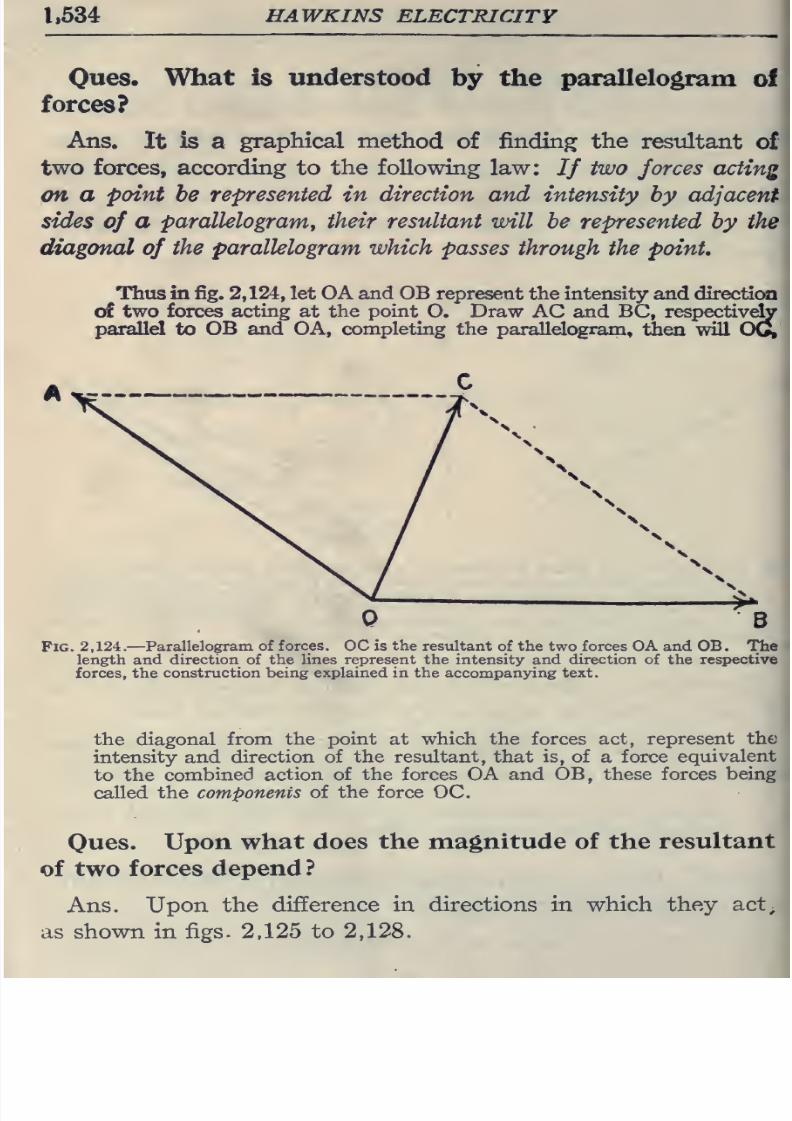
8/20/2019 electrical guide 5.pdf
http://slidepdf.com/reader/full/electrical-guide-5pdf 280/343
1,534
HAWKINS
ELECTRICITY
Ques.
What
is
understood
by
the
parallelogram
of
forces?
Ans.
It
is
a
graphical
method
of
finding
the
restiltant
of
two
forces,
according to
the
following
law: If
two
forces acting
on a
point
be
represented
in
direction
and
intensity
by adjacent-
sides
of
a
parallelogranty their
resultant
will be
represented
by
the
diagonal
of
the parallelogram which
passes
through the
point.
Thus
in
fig.
2,124,
let OA
and OB
represent
the
intensity and
direction
of
two
forces
acting
at
the
point
O. Draw
AC and BC,
respectivdy
parallel
to
OB
and
OA, completing the
parallelogram,
then will
OG,
Pig.
2,124.
—
Parallelogram of
forces.
DC
is
the
resultant
of the two
forces OA and
OB. The
length and
direction
of the lines
represent
the
intensity
and
direction of
the
respective
forces, the
construction
being explained
in the
accompanying
text.
the diagonal
from
the
point
at
which
the forces
act,
represent
the
intensity and
direction of
the resultant,
that
is,
of
a
force
equivalent
to the
combined
action
of the
forces
OA
and
OB,
these
forces
being
called
the components
of
the
force
OC.
Ques.
Upon
what
does
the
magnitude
of
the
resultant
of
two forces
depend
?
Ans.
Upon
the
difference
in
directions
in
which they
act;
as
shown in
figs.
2.125
to
2,128.
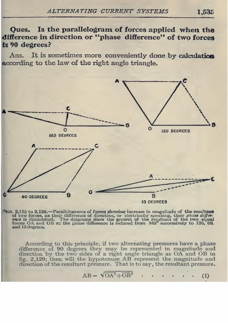
8/20/2019 electrical guide 5.pdf
http://slidepdf.com/reader/full/electrical-guide-5pdf 281/343
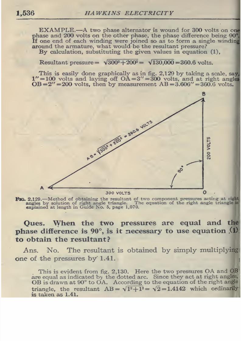
8/20/2019 electrical guide 5.pdf
http://slidepdf.com/reader/full/electrical-guide-5pdf 282/343
1,536
HAWKINS
ELECTRICITY
EXAMPLE.
—
A
two
phase alternator
is
wound
for
300 volts
on one
phase
and 200 volts
on
the other
phase,
the
phase
difference
being
90 .
If
one end
of each winding were joined
so as to
form
a
single
winding
around
the
armature, what
would
be
the
resultant
pressure?
By
calculation,
substituting
the
given
values
in
equation
(1),
Resultant pressure
=
VSOO^
+200^
=
Vl30,000
=
360.6
volts.
This is easily done
graphically
as
in fig.
2,129
by
taking
a
scale,
say,
1
=
100
volts and
laying
off
OA=3 =300
volts, and
at
right
angled
OB
=2
=200
volts,
then
by
measurement
AB
=3.606
=
360.6
volts.
300
VOLTS
Pig.
2,129.
—Method of
obtaining
the
resultant
of two
component pressures
acting
at
right
angles by
solution
of right
angle
triangle.
The
equation of
the
right angle
triangle
is
explained
at
length
in
Guide No.
5,
page
1,070.
Owes.
When
the
two
pressures
are
equal
and
the
phase
difference
is
90°,
is it
necessary
to
use
equation
.(l)
to
obtain
the resultant?
Ans.
No.
The resultant is
obtained
by
simply
mtiltiplying
one
of
the
pressures
by
1.41.
This
is
evident from
fig.
2,130.
Here
the two
pressures
OA
and
OB
are
equal as
indicated by the dotted arc.
Since
they
act
at
right
angles,
OB is
drawn at
90°
to
OA. Acco
rding
to
the
equation of
the
right
angle
triangle,
the
resultant
AB=
VP+P=
V2
=
1.4142
which
ordinarily
is
taken
as
1.41.
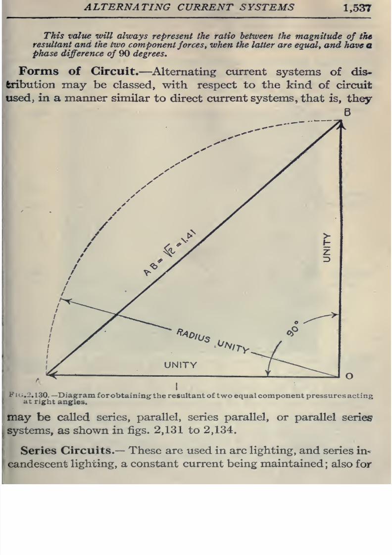
8/20/2019 electrical guide 5.pdf
http://slidepdf.com/reader/full/electrical-guide-5pdf 283/343
ALTERNATING
CURRENT
SYSTEMS
1,537
This
value
will
always
represent the ratio between
the magnitude
of
the
resultant
and
the two
component
forces,
when
the latter
are equal,
and
have
a
phase
difference
of
90
degrees.
Forms
of Circuit.
—
^Alternating
current
systems
of
dis-
fcribution
may
be
classed,
with
respect
to
the
kind
of
circuit
used,
in
a
manner
similar
to
direct
current
systems,
that
is,
they
B
y^
/
/
^^'
^-40
'lUs
^^iTy
UNITY
Fig.
2,130. —Diagram
forobtaining
the resultant of
two
equal component
pressures
acting
at
right
angles.
may
be
called
series,
parallel, series parallel,
or parallel
series
systems,
as
shown
in
figs. 2,131 to
2,134.
Series
Circuits.—
These are
used
in
arc
lighting,
and
series
in^
candescent
lighting,
a
constant
current
being
maintained;
also
for
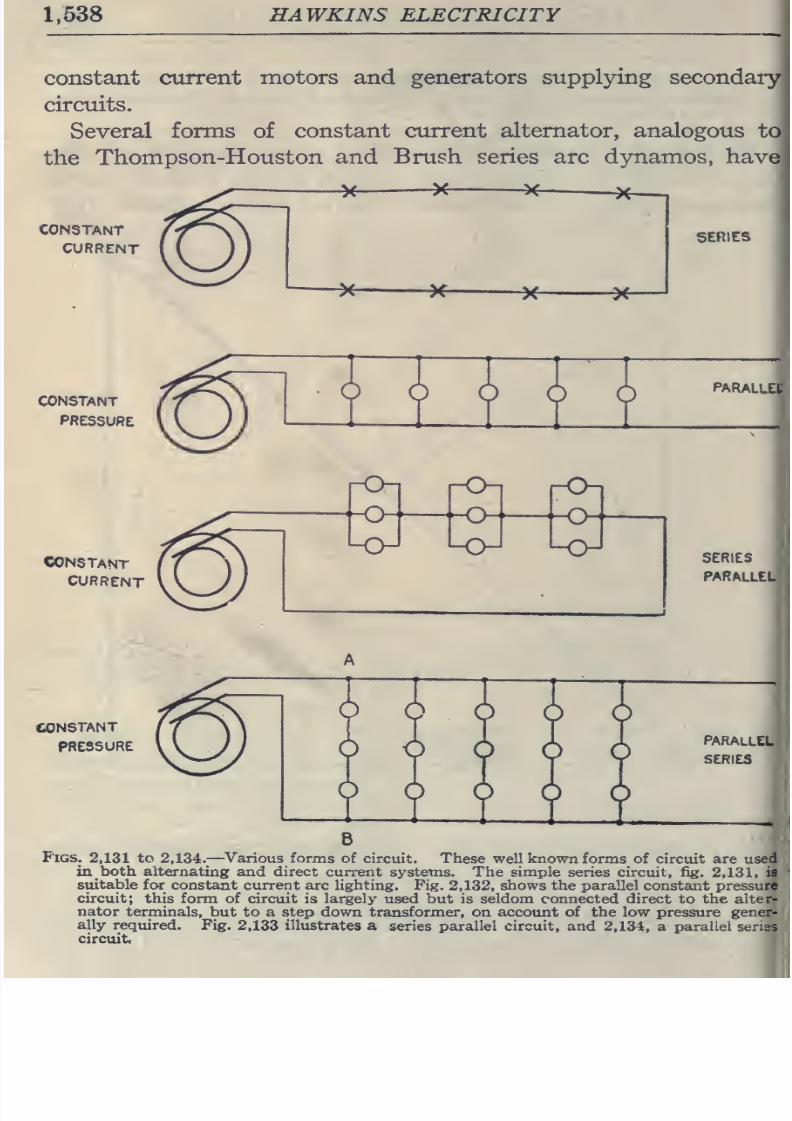
8/20/2019 electrical guide 5.pdf
http://slidepdf.com/reader/full/electrical-guide-5pdf 284/343
1,638
HAWKINS ELECTRICITY
constant
current
motors and generators supplying secondaiy
circuits.
Several
forms of
constant current
alternator,
analogous to
the
Thompson-Houston
and
Brush
series arc
dynamos, have
-y
^
X-
SERIES
CONSTANT
CURRENT
SERIES
PARALLEL
CONSTANT
PRESSURE
PARALLEL
SERIES
B
Figs.
2,131
to
2,134.
—
Various
forms
of
circuit.
These
well
known
forms
of
circuit
are
used
in
both
alternating and direct current
systems.
The simple
series
circuit,
fig.
2,131,
is
suitable for
constant
current
arc
lighting. Fig.
2,132,
shows the parallel
constant
pressure
circuit;
this form of
circuit
is
largely
used
but
is
seldom
connected direct to
the alter-
nator
terminals,
but to a step
down
transformer, on account of the
low
pressure
gener-
ally
reqtiired.
Fig.
2,133
illustrates
a
series
parallel circuit,
and
2,134,
a
parallel
senss
circuit
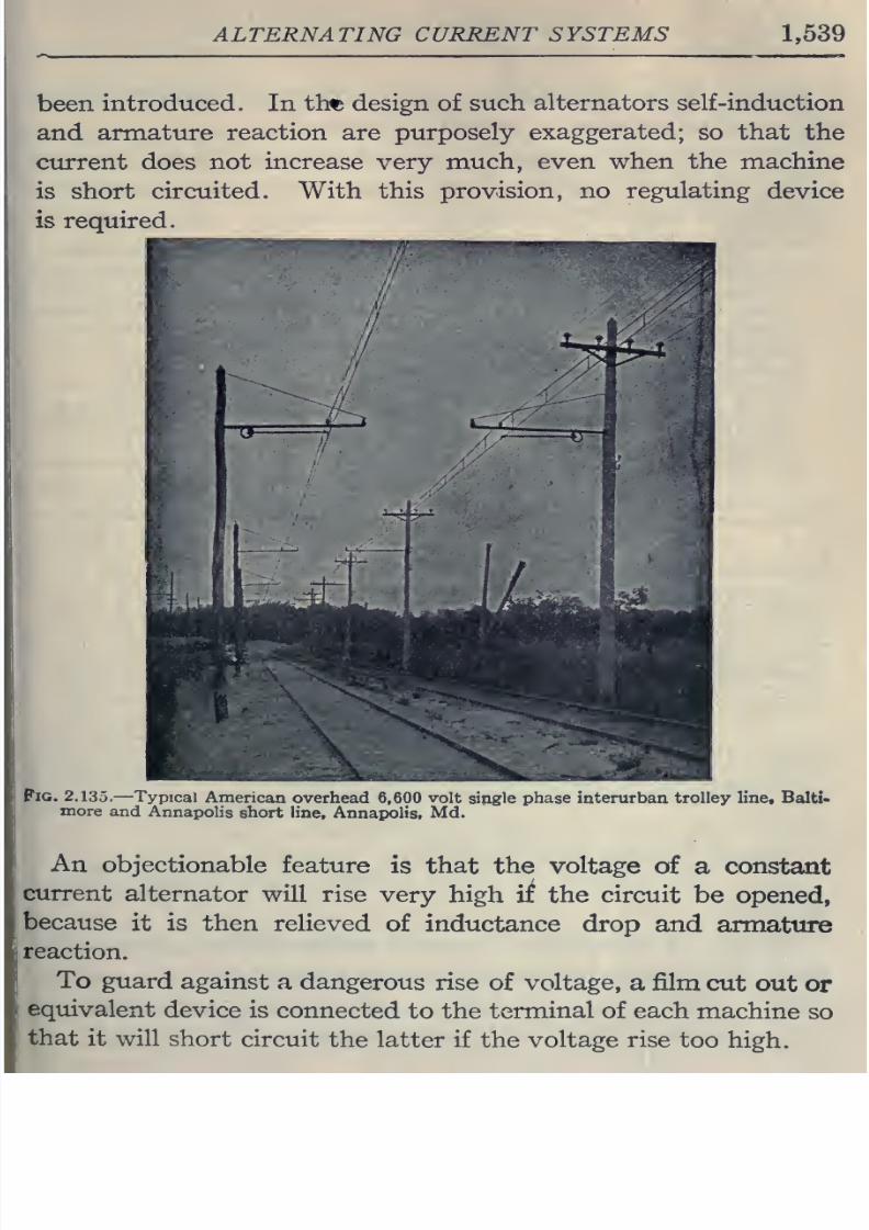
8/20/2019 electrical guide 5.pdf
http://slidepdf.com/reader/full/electrical-guide-5pdf 285/343
ALTERNATING
CURRENT SYSTEMS
1,539
been
introduced.
In thft
design
of
such
alternators
self-induction
and
armature
reaction are
purposely exaggerated;
so
that
the
current does not
increase
very
much,
even
when the
machine
is
short
circuited.
With
this
provision,
no
regulating
device
is
required.
Pig.
2.135.
—
Typical
American
overhead
6,600
volt
single phase
interurban
trolley
line,
Balti*
more
and
AnnapoHs
short
line, Annapolis,
Md.
An
objectionable
feature
is that the
voltage
of
a constant
current
alternator
will
rise
very
high
if
the circuit
be
opened,
because
it is
then relieved
of
inductance
drop
and
armattire
reaction.
To
guard
against
a dangerous
rise
of
voltage,
a
film
cut
out
or
equivalent
device
is
connected
to the
terminal
of each
machine
so
that
it
will
short
circuit
the latter
if
the
voltage
rise
too
high.
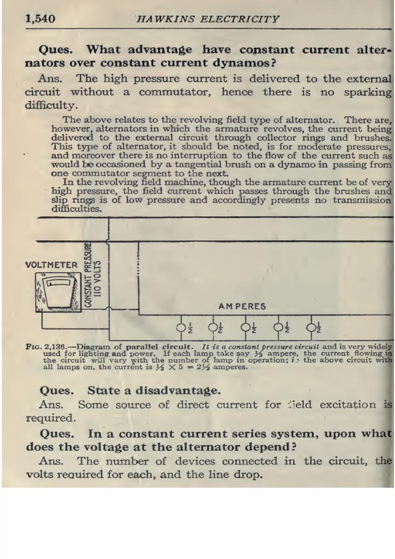
8/20/2019 electrical guide 5.pdf
http://slidepdf.com/reader/full/electrical-guide-5pdf 286/343
1,540
HAWKINS ELECTRICITY
Ques.
What
advantage have
constant
current
alter-
nators
over constant
current
dynamos?
Ans.
The high pressure
current is
deHvered
to
the external
circuit without a commutator, hence there
is
no
sparking
difficulty.
The
above
relates
to the
revolving
field type
of
alternator.
There
are,
however,
alternators
in
which the
armature revolves,
the
current
being
delivered
to
the external
circuit through
collector
rings
and
brushes.
This type
of alternator,
it
should
be noted,
is
for
moderate pressures,
and
moreover there
is
no
interruption
to the flow of
the
current such
as
would
be
occasioned by
a tangential brush
on a djmamo in
passing
from
one
commutator
segment to the next.
In
the
revolving field machine, though the
armature current be of
very
high
pressure,
the
field current
which
passes
through
the
brushes
and
slip
rings
is of
low
pressure
and
accordingly
presents no
transmission
difficulties.
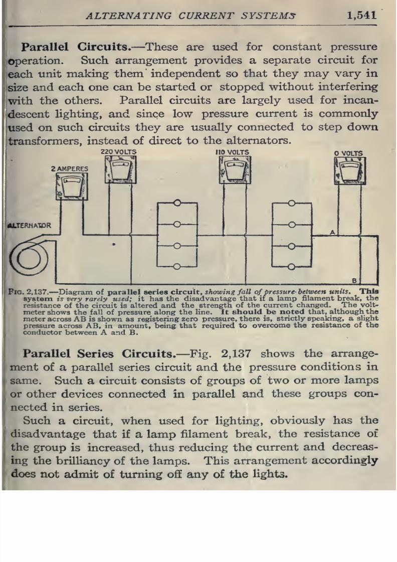
8/20/2019 electrical guide 5.pdf
http://slidepdf.com/reader/full/electrical-guide-5pdf 287/343
ALTERNATING CURRENT
SYSTEMS
1,541
Parallel
Circuits.
—
These are
used
for constant
pressure
operation.
Such
arrangement
provides
a
separate circuit for
each
unit
making
them independent so
that
they
may vary
in
size
and
each
one can be
started
or
stopped
without
interfering
with
the
others. Parallel
circuits
are
largely
used for
incan-
descent
lighting,
and
since
low
pressure
current is
commonly
used
on
such
circuits
they
are usually
connected to step down
transformers,
instead
of
direct to
the
alternators.
22
VOLTS
l
|0
VOLTS
VOLTS
Pig.
2,137.
—Diagram
of
parallel series
circuit,
showing fall
of
pressure-
between
units. This
system
is very rarely
used;
it
has
the
disadvantage
that
if
a
lamp
filament break,
the
resistance
of the
circuit
is
altered and
the strength of
the
current changed.
The volt-
meter
shows the fall
of pressure
along
the
line.
It
sliould be
noted that,
although
the
meter
across
AB
is shown as
registering
zero pressure, there
is,
strictly
speaking,
a
slight
pressure across
AB,
in
amount, being that
required
to
overcome
the
resistance
of
the
conductor
between A
and
B.
Parallel
Series Circuits.
—
Fig.
2,137
shows
the
arrange-
ment
of
a parallel series circuit
and the
pressure
conditions
in
same.
Such a
circuit consists of groups
of
two
or
more lamps
or
other
devices
connected
in
parallel
and
these
groups
con-
nected
in series.
Such
a
circuit,
when
used
for
lighting,
obviously has
the
disadvantage
that
if
a lamp
filament
break,
the
resistance
of
the
group
is
increased,
thus
reducing the
current
and
decreas-
ing
the
brilliancy
of
the
lamps. This
arrangement
accordingly
does
not
admit
of
turning ofiE any
of the
lights.
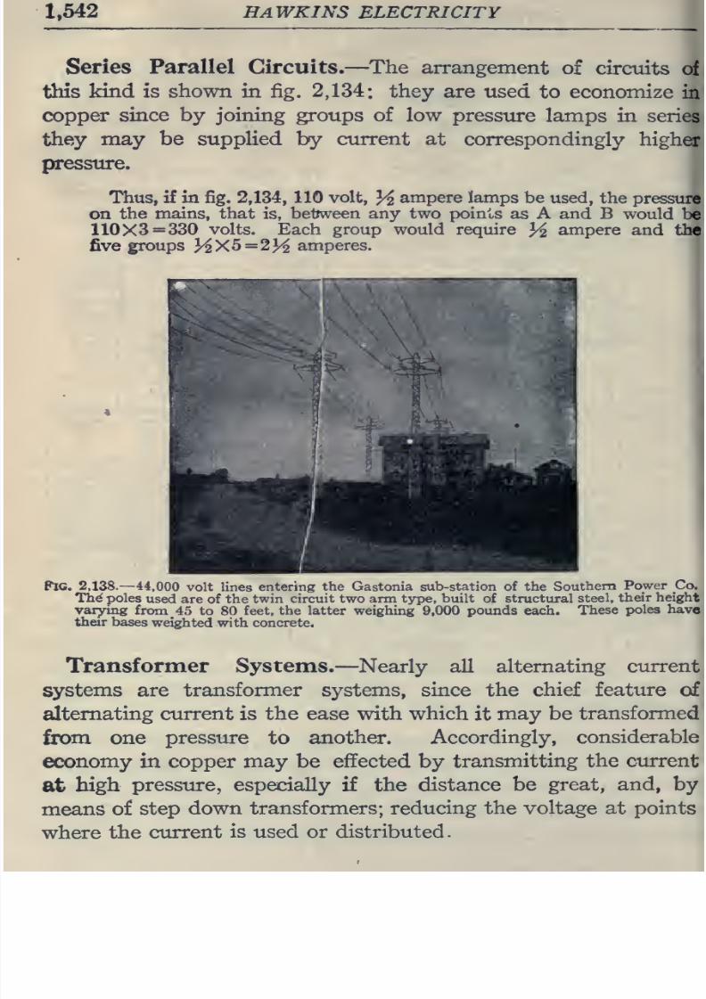
8/20/2019 electrical guide 5.pdf
http://slidepdf.com/reader/full/electrical-guide-5pdf 288/343
1,542
HAWKINS ELECTRICITY
Series
Parallel
Circuits.—
The
arrangement
of ciroiits
of
this
kind
is
shown
in
fig. 2,134: they are used
to
economize
in
copper
since
by joining groups of low
pressure
lamps
in
series
they
may be
supplied by
current
at
correspondingly
higher
pressure.
Thus, if
in
fig.
2,134,
110
volt,
14
ampere
lamps
be used,
the
pressure
on
the
mains, that
is,
betnveen
any
two points
as A
and
B
would
be
110X3
=
330
volts.
Each
group
would
require
3^
ampere
and
the
five
groups
KX5=23^
amperes.
Pic.
2,138.-44,000
volt lines
entering
the
Gastonia
sub-station
of
the
Southern
Power
Co.
Th^
poles
used
are of
the twin
circuit two arm type,
built
of structural
steel,
their
height
varying
from
45
to
80
feet,
the
latter
weighing
9,000
pounds
each.
These
poles
have
their
bases
weighted with concrete.
Transformer
Systems.
—Nearly all
alternating current
systems
are
transformer systems, since the
chief
feature
of
alternating
current
is
the
ease
with
which
it
may
be
transformed
from
one
pressure
to
another.
Accordingly,
considerable
economy
in
copper
may
be
effected
by
transmitting
the
current
at
high
pressure,
especially
if
the
distance
be
great,
and,
by
means
of
step
down transformers; reducing
the
voltage at points
where
the
current
is
used
or distributed.
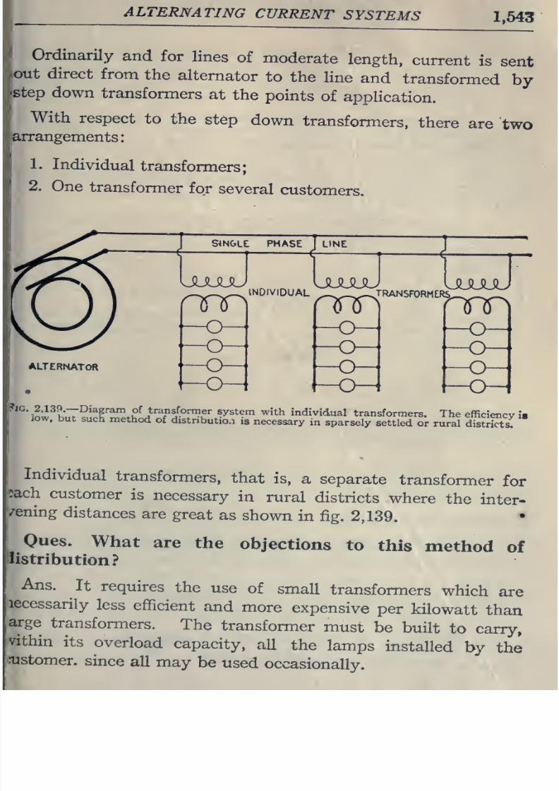
8/20/2019 electrical guide 5.pdf
http://slidepdf.com/reader/full/electrical-guide-5pdf 289/343
ALTERNATING
CURRENT
SYSTEMS
1,543
:
Ordinarily
and
for
lines
of
moderate
length,
current
is
sent
out
direct
from
the
alternator
to
the
line
and
transformed
by
'Step
down
transformers
at
the
points
of
application.
With
respect
to
the
step
down
transformers,
there are
two
arrangements
1.
Individual
transformers;
2.
One
transformer
for
several
customers.
SINGLE
PHASE
LINE
nnn ° *'
nnpi'^' ' 7nn
ALTERNATOR
^^*^*
iJ;^^ K
T°'^f
' ^ ^
^^^' ^ sforTner
system
with
individual
transformers.
The
efficiency
i«
low.
but
such
method
of
distribution
is
necessary
in
sparsely
settled
or
rural
S^tZ
Individual
transformers,
that
is,
a
separate
transformer
for
i?ach
customer
is
necessary
in
rural
districts
where
the
inter-
'/ening
distances
are
great
as
shown
in
fig.
2,139.
•
Oues.
What
are
the
objections
to
this
method
of
listribution?
Ans.
It
requires
the
use
of
small
transformers
which
are
less
efficient
and
more
expensive
per
kilowatt
than
arge
transformers.
The
transformer
must
be
built
to
carry,
vithin
its
overload
capacity,
all
the
lamps
installed
by
the
rustomer.
since
all
may
be
used
occasionally.
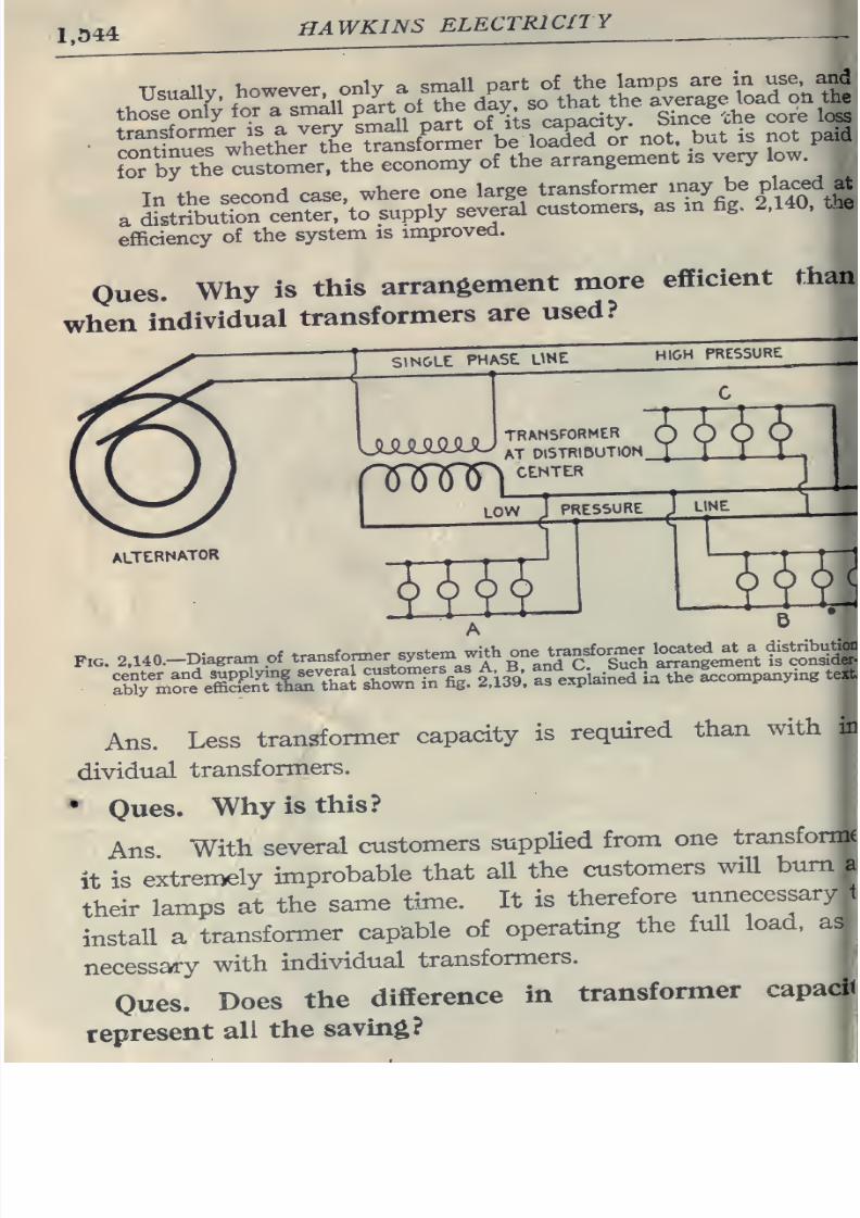
8/20/2019 electrical guide 5.pdf
http://slidepdf.com/reader/full/electrical-guide-5pdf 290/343
1.044
HAWKINS
ELECTRICITY
In
the
second
case,
where
one
large
transformer
may
be
placed
at
a
L^strllutforceriter/to
supply
several
customers,
as
m
fig. 2.140.
the
efficiency
of
the
system
is
improved.
Oues.
Why
is
this
arrangement
more
efficient
than
when
individual
transformers
are
used?
SINGLE
PHASE
UNE
HIGH
PRESSURE
UUJU5JUJ
TRANSFORMER
AT
DISTRIBUTION.
CENTER
m±
LOW
1
PRESSURE
J
LINE
ALTERNATOR
SH
H:
im
Fxc.
2a40.-Diagrarn
of
transfonner
s^^^^^^^^^
.
Sr--^SS tirtha1
rwTff
fig
2^:13^9.
Ifexpiained
ia
the
accompanying
text
Ans. Less transformer
capacity
is
required
than
with
in
dividual
transformers.
•
Ones.
Why
is
this?
Ans
With
several
customers
supplied
from
one
transforms
it
is
extremely
improbable
that
all
the
customers
will
bum
a
their
lamps
at
the
same
time.
It
is
therefore
unnecessary
1
install
a
transformer capable
of
operating the
full
load,
as
necessary
with
individual
transformers.
Oues.
Does
the
difference
in
transformer
capacij
represent
all
the
saving?
en
i
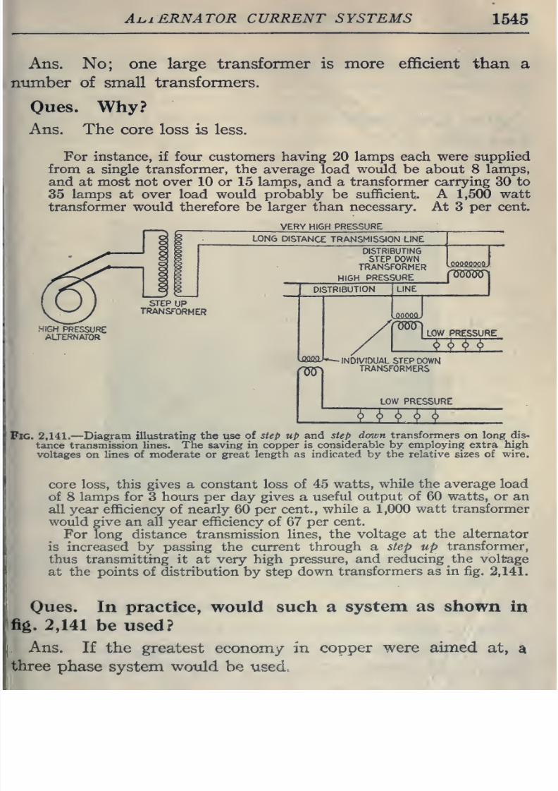
8/20/2019 electrical guide 5.pdf
http://slidepdf.com/reader/full/electrical-guide-5pdf 291/343
Ai^iERNATOR
CURRENT SYSTEMS
1545
Ans. No;
one large transformer
is more
efficient
than
a
number of small
transformers.
Oues.
Why?
Ans. The
core
loss
is less.
For
instance,
if four
customers
having
20
lamps
each were
supplied
from
a
single transformer, the average
load
would
be
about 8
lamps,
and
at most
not
over 10
or
15 lamps,
and
a
transformer carrying
30
to
35
lamps at
over
load
would
probably
be
sufficient. A
1,500
watt
transformer would therefore
be
larger
than
necessary. At
3
per
cent.
VERY
HIGH
PRESSURE
LONG
DISTANCE
TRANSMISSION
LINE
STEP
UP
TRANSFORMER
HIGH
PRESSURE
AUERNAFOR
DISTRIBUTING
STEP
DOWN
„„„„„^„
TRANSFORMER
^^
HIGH
PRESSUR
E
f
00000
DISTRIBUTION
LINE
TOTj
LOW
PRESSURE
^^
-INDIVIDUAL
STEP
DOWN
TRANSFORMERS
LOW PRESSURE
^ ^ ^ ^ ^
Fig.
2,141.
—
Diagram
illustrating
the
use
of
step
up
and
step
down
transformers
on long
dis-
tance transmission
lines.
The
saving in
copper is
considerable by
employing
extra
high
voltages on lines
of moderate or great length as
indicated
by
the relative
sizes
of wire.
core
loss,
this
gives
a
constant
loss
of
45
watts,
while the
average
load
of
8
lamps for 3 hours
per
day
gives
a
useful output
of
60
watts,
or an
all
year
efficiency
of
nearly
60
per cent.,
while
a
1,000
watt transformer
would give
an all
year
efficiency
of
67
per
cent.
For
long
distance
transmission
lines,
the voltage
at
the alternator
is increased
by
passing
the
current
through a
step
up
transformer,
thus transmitting it
at
very high pressure,
and
reducing
the
voltage
at
the
points of distribution
by step
down
transformers
as
in fig.
2,141.
Oues.
In
practice,
would
such
a
system
as
shown
in
fig.
2,141
be
used?
Ans.
If
the greatest
economy
in
copper were
aimed
at,
a
three
phase
system
wotild be
used.
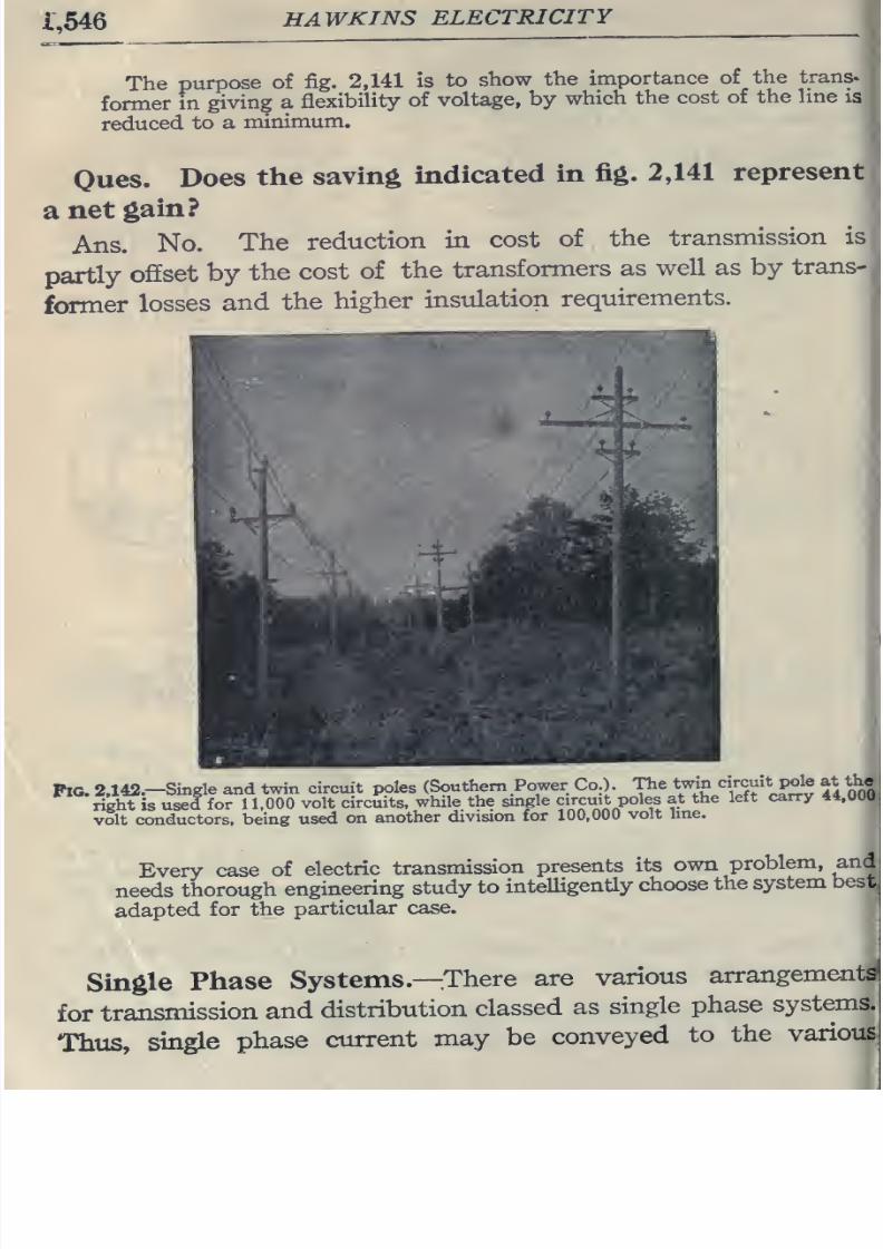
8/20/2019 electrical guide 5.pdf
http://slidepdf.com/reader/full/electrical-guide-5pdf 292/343
i;546
HAWKINS
ELECTRICITY
The
purpose
of
fig.
2,141
is
to
show
the
importance
of
the
trans^
former
in
giving a
flexibility
of
voltage,
by
which
the
cost
of
the
line
is
reduced
to
a
minimum.
Oues.
Does
the
saving
indicated
in
fig.
2,141
represent
a
net
gain?
Ans.
No.
The
reduction
in
cost
of
,
the
transmission
is
partly
offset
by
the
cost
of
the
transformers
as
well
as
by
trans-
former
losses
and
the
higher
instdation
requirements.
Pig.
2.142.-Smgle
and
twin
circuit
poles
(Southern
Power Co.).
The
twin
circuit
pole at
th«
right
is
used
for
11.000
volt
circuits,
while
the
single
circuit
poles
at
the
left
carry 44,000,
volt
conductors,
being
used
on
another
division
tor
100,000
volt
line.
Every
case
of
electric
transmission
presents
its
own
problem,
and
needs
thorough
engineering
study
to
intelligently
choose
the
system
best
adapted
for the
particular
case.
Single
Phase
Systems.—
There
are
various
arrangements
for
transmission
and
distribution
classed
as
single
phase
systems.
Thus,
single
phase
current
may
be
conveyed
to
the
various
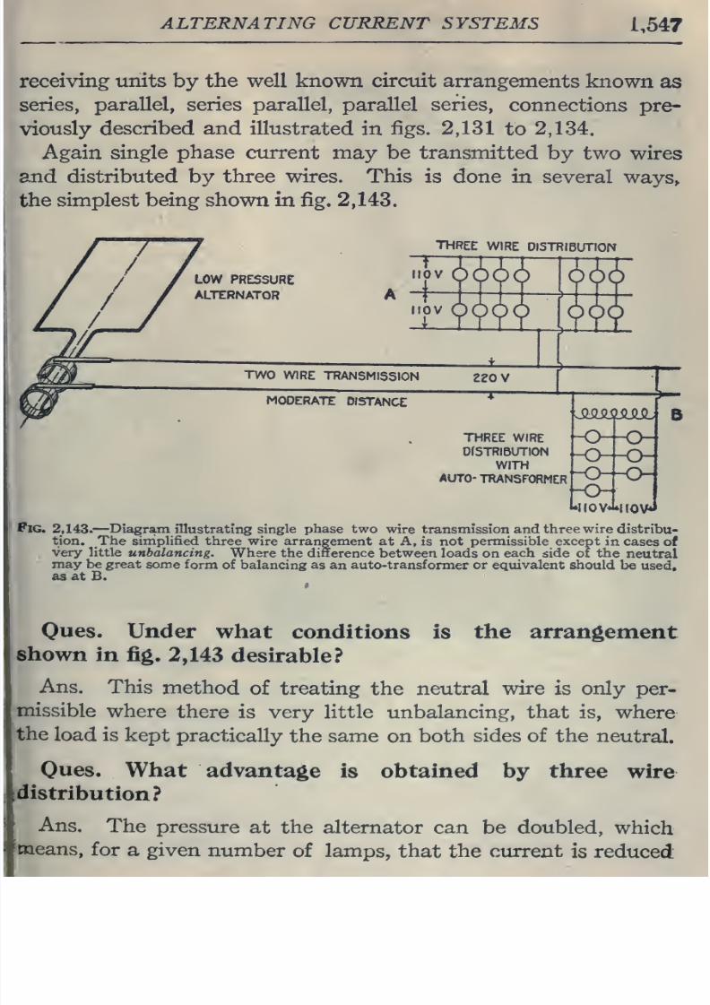
8/20/2019 electrical guide 5.pdf
http://slidepdf.com/reader/full/electrical-guide-5pdf 293/343
ALTERNATING
CURRENT SYSTEMS
1,547
receiving
units
by
the
well known
circuit
arrangements
known
as
series,
parallel,
series
parallel,
parallel
series,
connections
pre-
viously
described
and illustrated
in
figs.
2,131
to
2,134.
Again
single
phase
current
may
be
transmitted
by
two
wires
and distributed
by
three wires. This
is done
in several
ways,,
the
simplest being shown
in
fig.
2,143.
THREE
WIRE
DI5TRI6UTION
THREE WIRE
DfSTRlBUTION
WITH
AUTO-
TRANSFORMER
-o-
HiovJ»nov»»
Fig.
2.143.
—
Diagram
illustrating
single
phase
two
wire transmission and
three wire
distribu-
tion.
The
simplified
three
wire arrangement
at A,
is
not
permissible
except
in
cases
of
.
very little
unbalancing.
Where
the difference between loads
on
each
side of
the
neutral
may be
great
some
form
of
balancing
as
an
auto-transformer
or equivalent
should
be
used,
as
at B.
Oues.
Under
what
conditions
is
the
arrangement
shown
in fig.
2,143
desirable?
Ans.
This
method
of treating
the neutral
wire
is
only
per-
missible
where
there
is very little unbalancing, that is,
where
the
load
is
kept
practically
the
same
on
both
sides
of
the
neutral.
Oues.
What
distribution?
advantage
is
obtained
by
three
wire
Ans.
The
pressure
at the alternator can
be
doubled,
which
'tneans,
for
a
given
number
of lamps,
that
the
current
is reduced
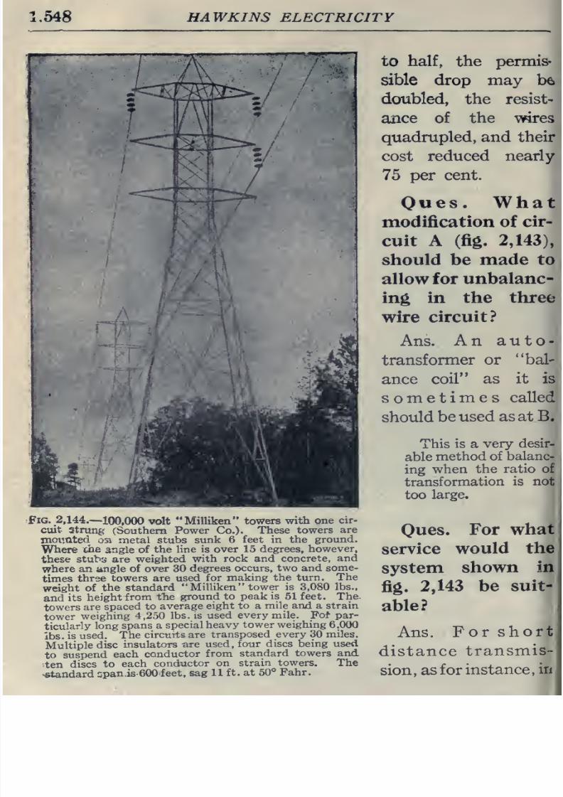
8/20/2019 electrical guide 5.pdf
http://slidepdf.com/reader/full/electrical-guide-5pdf 294/343
1.548
HAWKINS
ELECTRICITY
Fig.
2,144.-100,000
volt
Milliken towers
with one
cir-
cuit-
Stnmg
(Southern
Power
Co.).
These
towers
are
xnoiinted
osi
metal stubs
sunk 6
feet in
the
ground.
Where
ehe
angle
of
the
line is over
15 degrees,
however,
these
stubs are
weighted
with rock and
concrete,
and
where an
angle
of
over
30
degrees
occurs, two and
some-
times
three
towers
are used
for
making
the
turn.
The
weight
of the
standard
Milliken
tower is
3,080
lbs.,
and
its
height
from
the
ground
to
peak
is
51
feet. The
towers
are
spaced
to
average
eight
to
a mile
and
a
strain
tower
weighing
4,250
lbs.
is used
every
mile.
Fol-
par-
ticularly
long
spans a
special
heavy
tower weighing
6.000
lbs.
is
used.
The
circuits
are
transposed
every
30
miles.
Multiple
disc
insulators are
used,
four
discs being
used
to
suspend
each
conductor
from
standard
towers and
-ten
discs
to
each
conductor
on strain
towers.
The
•standard
span
is 600
feet,
sag
11
ft. at
50°
Fahr.
to half,
the
permis-
sible
drop
may
be
doubled, the resist-
ance
of
the
wires
quadrupled,
and
their
cost
reduced
nearly
75
per
cent.
Owes.
What
modification
of
cir-
cuit
A
(fig.
2,143),
should be
made
to
allow for
unbalanc-
ing
in
the three
wire
circuit?
Ans.
An a
u
t
o
transformer
or
bal-
ance
coil
as
it
is
sometimes
called
should
be
used
as
at B.
This
is a
very
desir-
able
method of
balanc-
ing
when
the
ratio
of
transformation
is
not
too
large.
Oues.
For
what
service
would
the
system
shown
in
fig.
2,143
be
suit-
able?
Ans.
For
short,
distance
transmis-
sion,
as
for
instance,
in
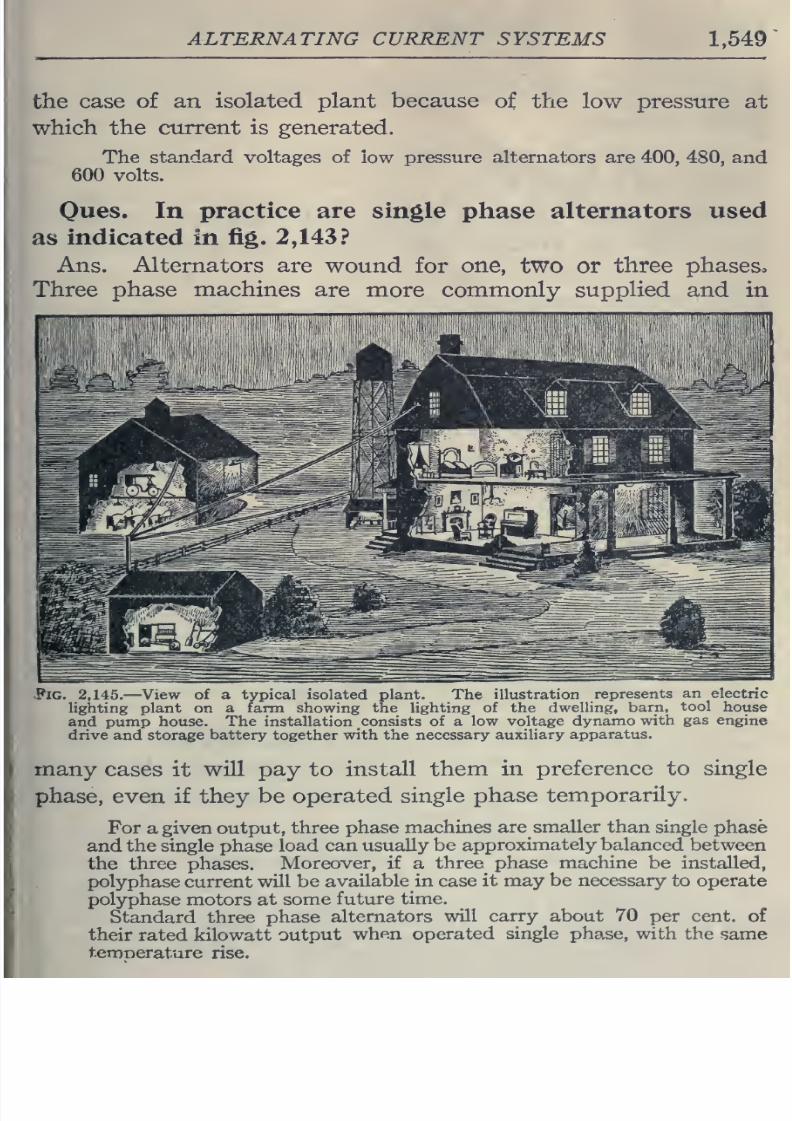
8/20/2019 electrical guide 5.pdf
http://slidepdf.com/reader/full/electrical-guide-5pdf 295/343
ALTERNATING
CURRENT
SYSTEMS
1,549
the
case
of
an
isolated plant
because
of
the
low pressure
at
which the
current is generated.
The
standard
voltages
of low
pressure alternators
are
400, 480,
and
600
volts.
Oues.
In
practice
are
single
phase
alternators used
as
indicated in
fig.
2,143?
Ans. Alternators are
wound for
one,
two
or
three phases.
Three
phase
machines
are more commonly
supplied and
in
Pig. 2,145.
—
View
of
a
typical
isolated
plant. The illustration
represents
an
electric
lighting plant
on
a farm showing the
lighting of
the
dwelling,
barn,
tool
house
and pump
house.
The
installation
consists
of
a
low
voltage
dynamo
with
gas
engine
drive and storage
battery
together
with
the
necessary auxiliary
apparatus.
many
cases
it
will
pay
to
install
them
in preference
to
single
phase,
even
if
they
be
operated
single
phase
temporarily.
For
a
given
output,
three phase
machines
are smaller than single
phase
and
the
single
phase
load
can usually
be
approximately
balanced between
the
three
phases.
Moreover,
if
a
three^
phase
machine
be installed,
polyphase current
will
be
available
in
case it may
be necessary
to
operate
polyphase
motors
at
some
future
time.
Standard
three
phase
alternators
will
carry
about
70
per
cent,
of
their
rated
kilowatt
output
when
operated
single
phase, with
the
same
temoerature
rise.
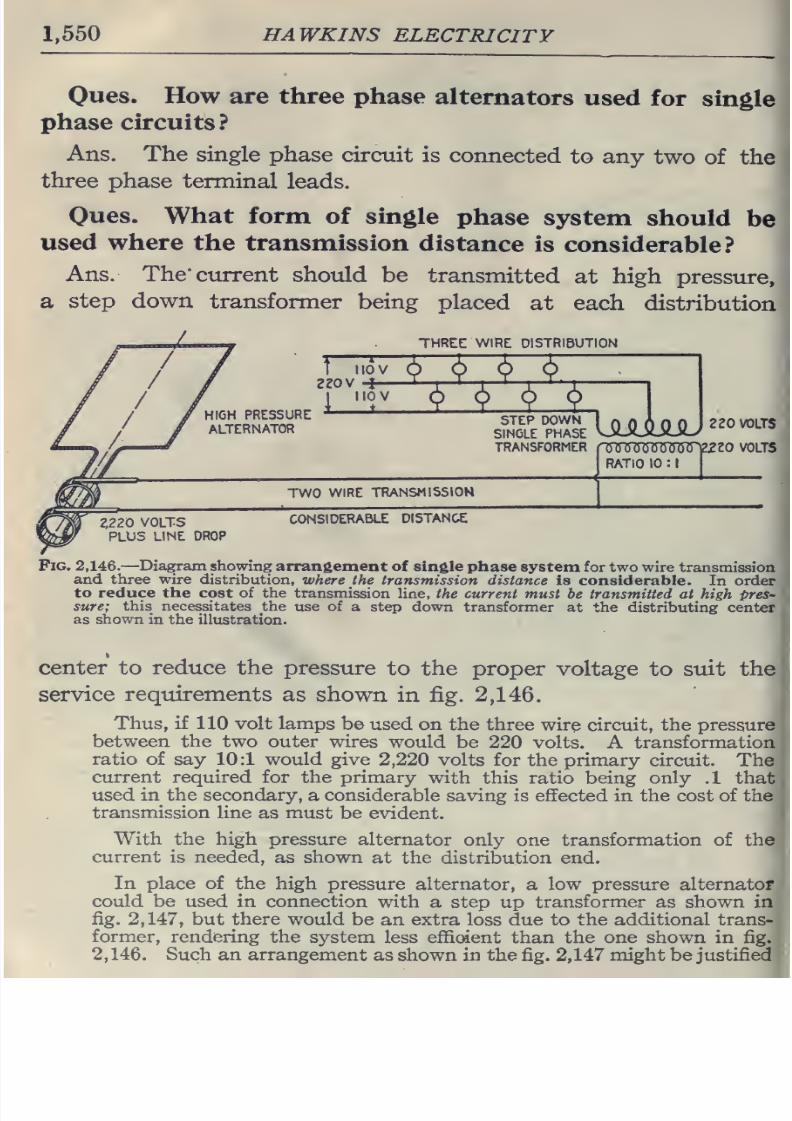
8/20/2019 electrical guide 5.pdf
http://slidepdf.com/reader/full/electrical-guide-5pdf 296/343
1,550
HAWKINS
ELECTRICITY
Oues.
How are three
phase
alternators
used for
single
phase
circuits?
Ans.
The single
phase
circuit
is
connected
to
any
two
of
the
three
phase
terminal
leads.
Oues.
What form
of single
phase
system
should
be
used
where
the
transmission
distance
is
considerable?
Ans.
The*
current
should
be
transmitted
at
high
pressure,
a
step
down
transformer
being
placed
at
each
distribution
three:
wire
distribution
T
iiov
2Z0V
4—
HIGH
PRESSURE
ALTERNATOR
IIOV
STEP
DOWN
SINGLE
PHASE
TRANSFORMER
JliimAmJ
220 VOLTS
ruTSiTismswvzzo volts
RATIO
10
:
TWO
WIRE
TRANSMISSION
2,220
VOLTS
PLUS
LINE
DROP
CONSIDERABLE
DISTANCE
Fig.
2,146.
—Diagram showing
arrangement
of single phase
system for two
wire transmission
and
three wire
distribution,
where
the
transmission
distance is considerable.
In order
to reduce
the
cost of the
transmission line,
the current
must be
transmitted
at
high pres-
sure;
this
necessitates the
use
of a
step
down
transformer
at
the distributing
center
as
shown
in the
illustration.
center
to
reduce
the
pressure
to
the
proper
voltage to
suit
the
service
requirements
as shown
in
fig.
2,146.
Thus,
if
110 volt
lamps be
used
on
the
three
wire
circuit,
the
pressure
between the two outer
wires
would
be 220
volts.
A
transformation
ratio
of say 10:1 would
give
2,220
volts for
the
primary circuit.
The
current required for the
primary
with
this ratio
being
only
.1
that
used
in
the
secondary,
a considerable
saving
is
effected
in the
cost
of the
transmission
line
as
must be
evident.
With the
high
pressure
alternator
only
one
transformation of the
current
is
needed, as
shown
at
the
distribution
end.
In
place of
the
high
pressure alternator,
a
low
pressure
alternator
could be used in
connection
with
a
step
up
transformer as shown in
fig.
2,147,
but
there
would
be
an extra loss
due to
the additional
trans-
former, rendering
the
system
less
effident
than
the
one
shown
in
fig.
2,
146.
Such an
arrangement
as shown
in
the
fig.
2,147
might
be
justified
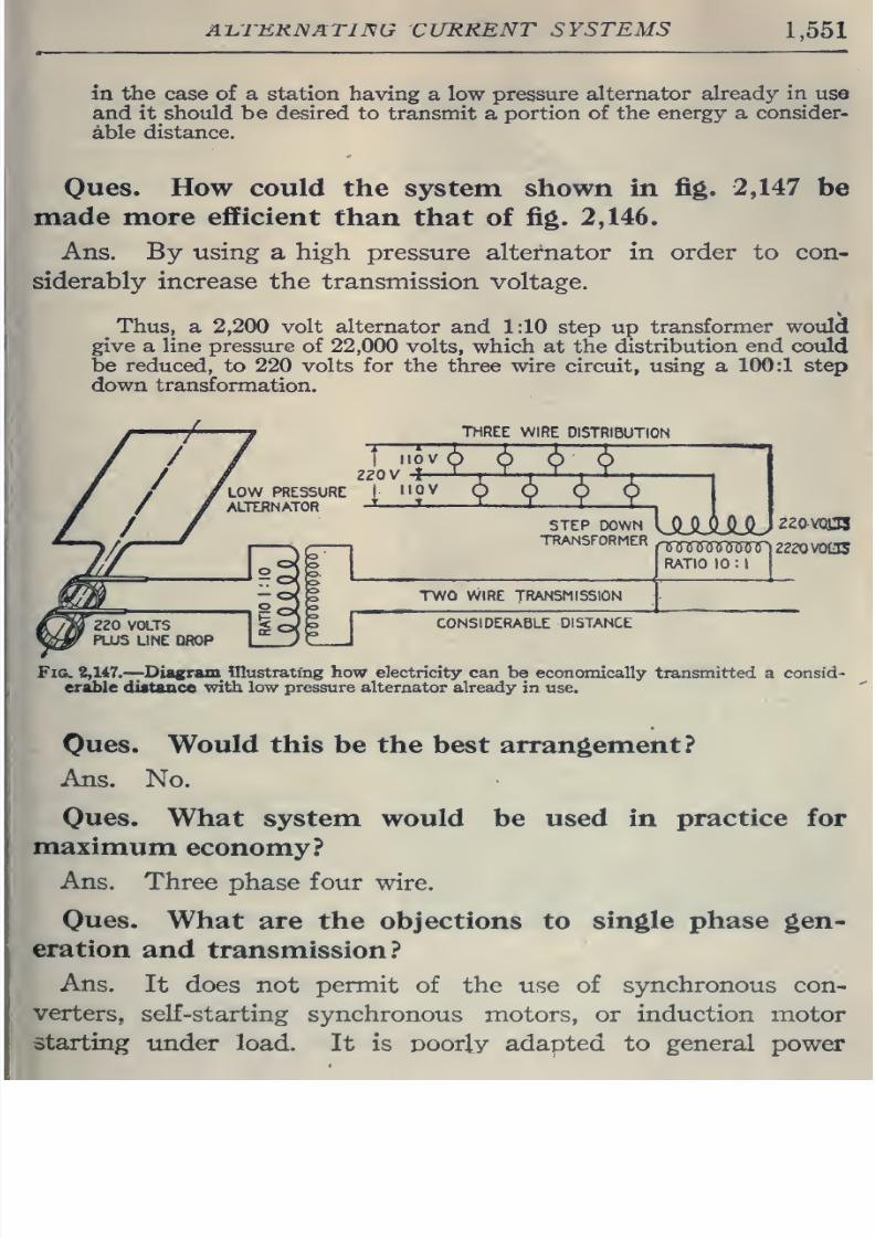
8/20/2019 electrical guide 5.pdf
http://slidepdf.com/reader/full/electrical-guide-5pdf 297/343
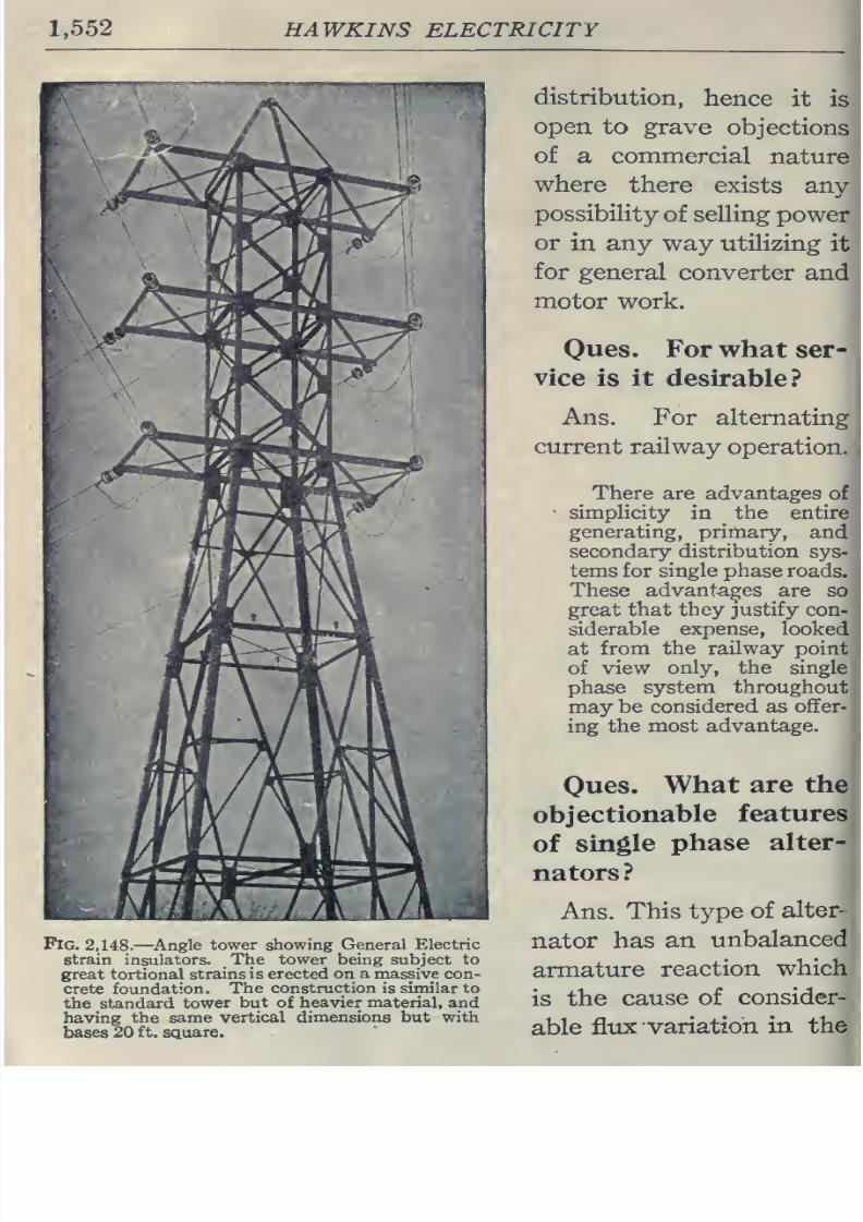
8/20/2019 electrical guide 5.pdf
http://slidepdf.com/reader/full/electrical-guide-5pdf 298/343
1,552 HAWKINS ELECTRICITY
Fig.
2,148.
—
Angle
tower showing
General
Electric
strain
insulators.
.The
tower being
subject
to
great
tortional
strains
is
erected
on a massive con-
crete
foundation.
The
construction
is
similar
to
the standard
tower
but
of
heavier
material,
and
having the
same vertical
dimensions
but
with
bases
20
ft.
square.
distribution,
hence
it
is
open
to
grave
objections
of
a
commercial
nature
where
there
exists
any
possibiHty
of
selling
power
or
in
any
way
utilizing
it
for
general
converter
and
motor work.
Oues.
For
what
ser-
vice
is
it
desirable?
Ans.
For
alternating
current
railway
operation.
There
are
advantages
of
-
simplicity
in
the
entire
generating,
primary,
and
secondary
distribution
sys-
tems for
single
phase roads.
These
advantages
are
so
great
that they justify
con-
siderable
expense,
looked
at
from
the railway
point
of
view
only,
the single
phase
system
throughout
may
be
considered as offer-
ing
the
most
advantage.
Oues.
What
are
the
objectionable
features
of
single
phase
alter-
nators?
Ans.
This
type
of
alter-
nator has
an
unbalanced
armature
reaction
which
is
the
cause
of
consider-
able
flux
variation
in the
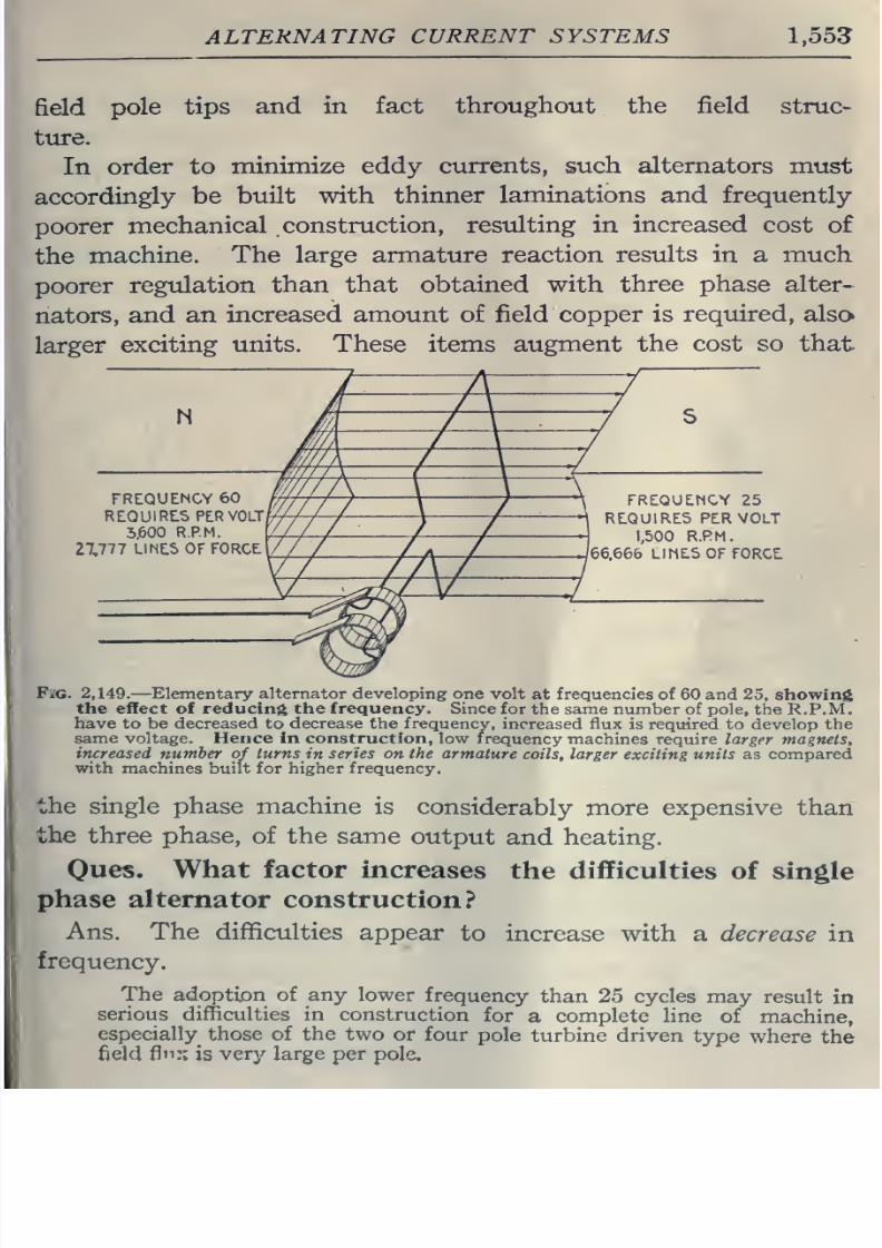
8/20/2019 electrical guide 5.pdf
http://slidepdf.com/reader/full/electrical-guide-5pdf 299/343
ALTERNATING
CURRENT
SYSTEMS
1,55?
field
pole
tips
and in fact
throughout
the field
struc-
ture.
In
order to
minimize
eddy
currents, such
alternators
must
accordingly
be
built
with
thinner laminations
and
frequently
poorer
mechanical
construction,
resulting
in
increased
cost of
the
machine.
The large armature reaction
results
in
a
much
poorer
regulation
than
that obtained
with
three phase
alter-
nators,
and an
increased
amount
of field
copper is
required,
also
larger
exciting
units. These items
augment
the cost so that
5,600
R.P.
27,777
LIMEIS
OF
FORCE
FREIQUENCY
25
RLQU1RE.S
PER
VOLT
1,500
R.RM.
66.666
LIMES
OF FORCE
P'iG.
2,149.
—Elementary
alternator
developing one
volt
at
frequencies
of
60 and
25,
showing
the
effect of
reducing
the
frequency.
Since for
the same number
of pole, the
R.P.M.
have
to
be decreased
to
decrease the frequency,
increased flux
is required to
develop
the
same voltage.
Hence in construction, low
frequency
machines require
larger
magnets,
increased
number
of
turns in series on the armature
coils, larger
exciting units
as
compared
with
machines
built for higher frequency.
the
single
phase
machine
is
considerably
more expensive
than
the three phase,
of the same
output
and
heating.
Oues.
What
factor
increases
the difficulties
of single
phase alternator construction?
Ans.
The
difficulties
appear
to
increase
with
a
decrease in
frequency.
The
adoption of
any
lower
frequency
than 25 cycles
may
result
in
serious difficulties in
construction
for
a
complete line
of
machine,
especially
those
of
the
two
or four
pole
turbine
driven
type
where
the
field
flu::
is
very
large
per
pole»
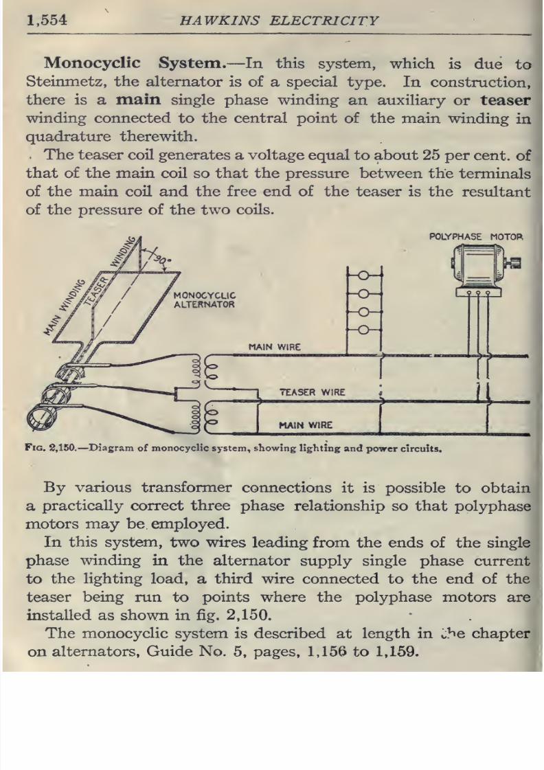
8/20/2019 electrical guide 5.pdf
http://slidepdf.com/reader/full/electrical-guide-5pdf 300/343
1,554
HAWKINS ELECTRICITY
Monocyclic
System.—
In
this
system,
which
is
due
to
Steinmetz,
the
alternator
is of
a
special
type.
In construction,
there is a
main
single
phase
winding
an
auxiliary
or
teaser
winding
connected
to
the
central
point
of
the
main
winding
in
quadrature therewith.
The
teaser
coil
generates
a
voltage
equal
to about
25
per
cent,
of
that
of the main coil
so
that the
pressure
between the
terminals
of the
main
coH and
the free end
of
the teaser is
the
resultant
of the
pressure of
the
two
coils.
POLYPHASE
MOTOf^
MAIN
WIRE
m
I
99?
I
TEASER WIRE
MAIN
WIRE
I
\
Fig.
2,150.—
Diagram
of
monocyclic system., showing
lighting
and
power
circuits.
By
various
transformer
connections
it is
possible
to
obtain
a
practically correct three phase
relationship
so
that polyphase
motors
may
be employed.
In
this system,
two wires
leading from
the
ends
of
the
single
phase
mnding
in
the
alternator
supply
single
phase current
to
the
lighting
load,
a
third
wire connected
to
the end
of
the
teaser
being
run
to
points
where the
polyphase
motors are
installed
as
shown
in
fig.
2,150.
The
monocyclic
system
is
described
at
length
in
ihe chapter
on
alternators, Guide
No.
5,
pages,
1,156 to
1,159.
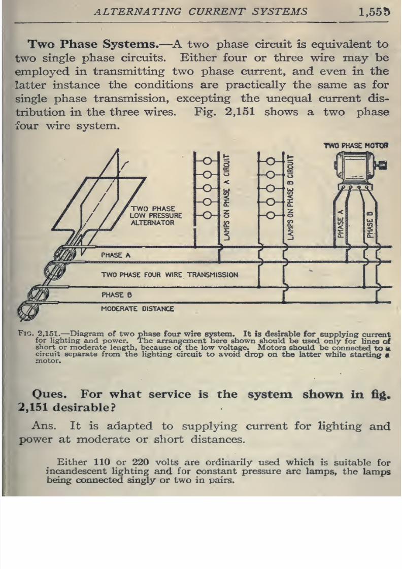
8/20/2019 electrical guide 5.pdf
http://slidepdf.com/reader/full/electrical-guide-5pdf 301/343
ALTERNATING CURRENT SYSTEMS
1.55b
Two
Phase
Systems.
—
^A two
phase
circuit
is
equivalent to
two
single
phase circuits.
Either
four
or
three
wire may be
employed in
transmitting
two
phase
current, and
even
in
the
latter
instance
the
conditions
are
practically
the
same
as
for
single
phase
transmission,
excepting
the unequal
current
dis-
tribution
in
the three
wires. Fig,
2,151
shows
a two phase
four
wire system.
TWO
PHASe
HOTQR
Fig.
2,151.
—
-Diagram
of
two phase
four
wire system.
It is desirable for
supplying
current
for
lighting
and power. The
arrangement here
shown should
be
used
only
for
lines
of
short
or
moderate
length,
because
of
the
low
voltage.
Motors
should
be
connected to
a
circuit
separate
from
the
lighting
circuit
to
avoid
drop
oa
the
latter while
starting
•
motor.
Ones.
For what
service
is the
system
shown
in
fig.
2,151
desirable?
Ans.
It
is adapted
to
supplying
current
for lighting
and
power
at moderate
or
short
distances.
Either
110
or
220
volts
are
ordinarily
used which
is
suitable
for
incandescent
lighting
and
for constant pressure
arc lamps,
the
lamps
being connected singly
or
two in
pairs.
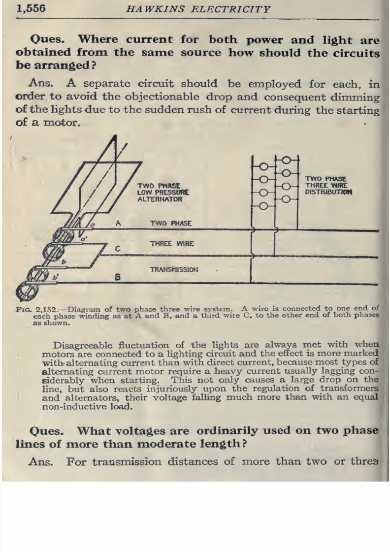
8/20/2019 electrical guide 5.pdf
http://slidepdf.com/reader/full/electrical-guide-5pdf 302/343
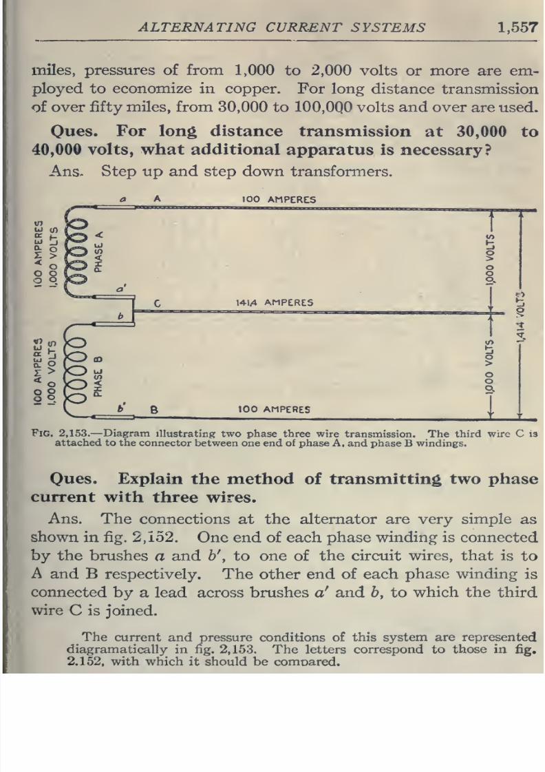
8/20/2019 electrical guide 5.pdf
http://slidepdf.com/reader/full/electrical-guide-5pdf 303/343
ALTERNATING
CURRENT
SYSTEMS
1,557
miles,
pressures
of from
1,000 to
2,000
volts
or more
are
em-
ployed
to
economize in
copper.
For
long
distance transmission
of
over
fifty miles, from
30,000
to
100,0Q0
volts
and
over
are
used.
Ones.
For
long distance
transmission
at
30,000 to
40,000
volts, what
additional
apparatus is
necessary?
Ans,
Step up and step
down
transformers.
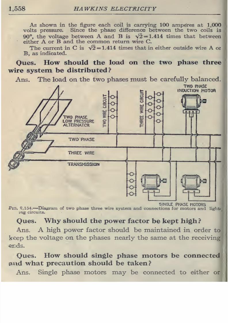
8/20/2019 electrical guide 5.pdf
http://slidepdf.com/reader/full/electrical-guide-5pdf 304/343
1,558
HAWKINS
ELECTRICITY
As
shown in
the figure each coil is carrying 100
amperes
at
1,000
volts
pressure.
Since
the
phase
difference between the two
coils
is
90°,
the
voltage
between A and B is
V2
=
1.414
times that
between
either
A
or
B and
the
common
return
wire
C.
The
current
in
C
is
V2
=
1.414
times that
in either
outside
wire
A
or
B,
as
indicated.
Oues.
How
should the
load
on
the
two
phase
three
wire
system be
distributed?
Ans.
The load on
the two phases must
be
carefully
balanced.
TWO
PHASE
INDUCTION
MOTOa
SINGLE
PHASE.
MOTORS
JPlG.
5,154.
—Diagram of
two
phase
three
wire
system and connections for motors
and
liglit-
mg
circuits.
Ques.
Why should
the
power
factor
be kept
high?
Ans.
A
high power
factor should
be
maintained
in
order
to
keep
the
voltage on
the
phases
nearly the
same
at the receiving
«nds.
Ques.
How
should
single
phase motors be
connected
^\d
what
precaution should
be
taken?
Ans.
Single
phase
motors may
be connected to
either
or
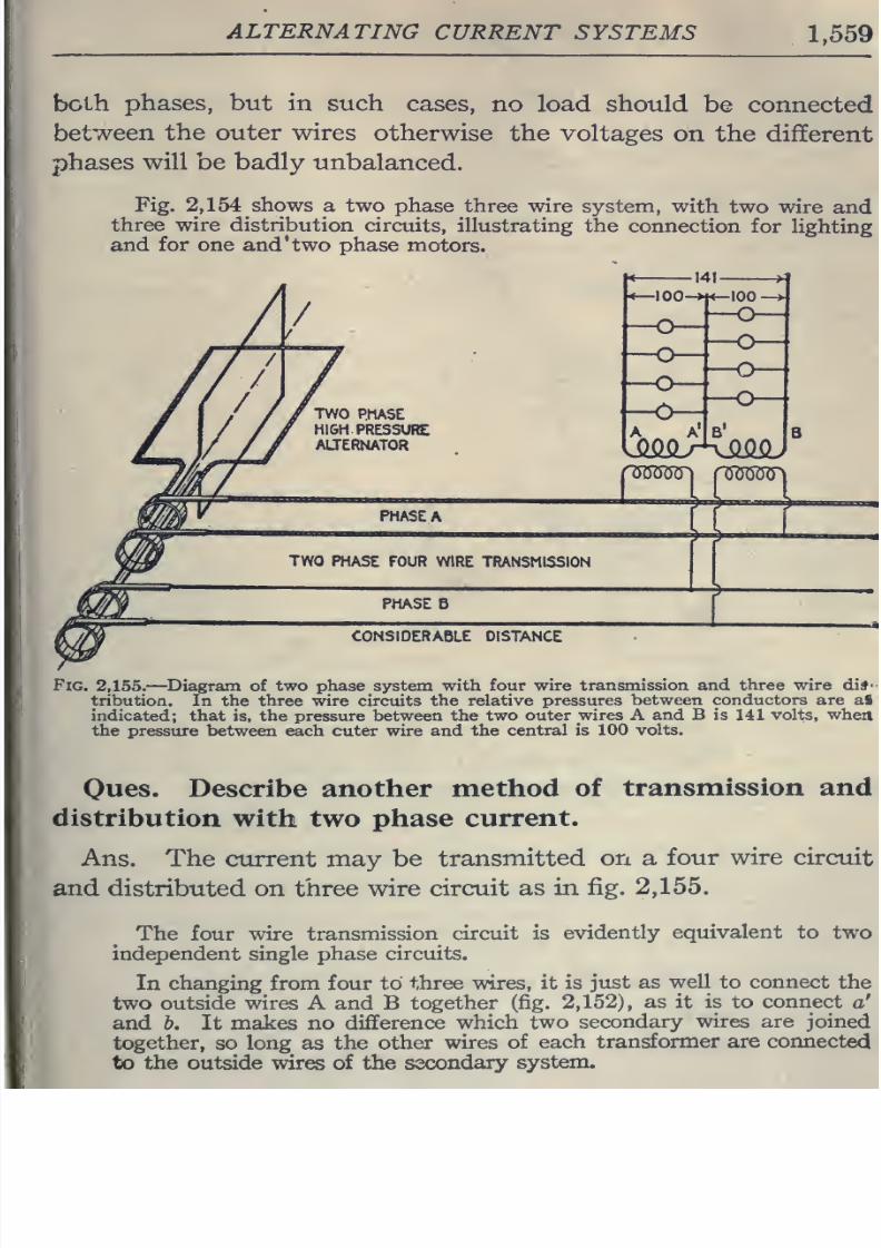
8/20/2019 electrical guide 5.pdf
http://slidepdf.com/reader/full/electrical-guide-5pdf 305/343
ALTERNATING
CURRENT
SYSTEMS
1,559
both
phases,
but in such
cases,
no
load
should
be
connected
between
the outer
wires
otherwise
the
voltages
on the
different
phases
will
be
badly
unbalanced.
Fig.
2,154
shows
a two
phase
three
wire
system, with
two wire
and
three
wire
distribution
circuits,
illustrating the
connection
for
lighting
and
for
one and*
two
phase
motors.
100
->
PHASE
A
nmuG
TWO
PHASE
FOUR WIRE
TRANSMISSION
PHASE
B
CONSIDERABLE
DISTANCE
Fig.
2,155.—
Diagram
of two phase system with
four
wire transmission
and three wire
di*'
tribution.
In
the
three wire circuits
the
relative
pressures between
conductors
are a§
indicated;
that is, the pressure between
the two
outer
wires
A
and
B is
141 volts, when
the
pressure between
each cuter
wire
and the
central is 100
volts.
Oues.
Describe
another
method
of
transmission
and
distribution
with
two phase
current.
Ans.
The
current
may
be
transmitted
on a
four
wire
circuit
and
distributed on three
wire
circuit as
in
fig.
2,155.
The
four
wire transmission
circuit
is
evidently
equivalent
to two
independent
single
phase
circuits.
In
changing from four
to
three wires,
it is
just
as
well
to connect
the
two outside
wires
A and B
together
(fig.
2,152),
as
it
is
to
connect
a'
and b.
It makes
no difference
which
two
secondary wires
are
joined
together,
so
long
as
the
other
wires
of
each transformer
are connected
to the
outside
wires
of
the
secondary
system.
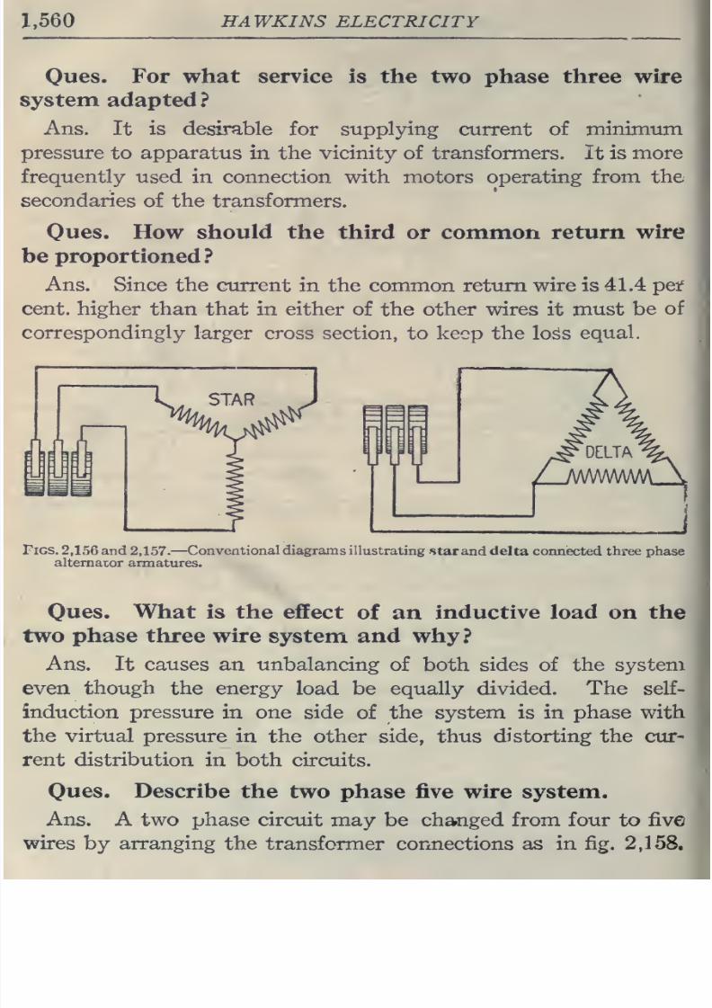
8/20/2019 electrical guide 5.pdf
http://slidepdf.com/reader/full/electrical-guide-5pdf 306/343
1,560
HAWKINS
ELECTRICITY
Oues.
For what
service is
the
two phase
three
wire
system adapted
?
Ans.
It
is
desirable
for
supplying
current
of minimum
pressure
to
apparatus
in
the
vicinity
of
transformers.
It
is
more
frequently
used
in
connection
with
motors
operating
from
the
secondaries
of the
transformers.
Oues. How
should
the third
or
common
return
wire
be proportioned
?
Ans.
Since
the
current
in
the common return
wire
is
41.4 pet
cent,
higher
than
that
in either
of
the
other
wires
it
must
be
of
correspondingly
larger
cross
section, to keep the loss
equal.
Figs.
2,156
and 2,157.
—
Conventional
diagrams
illustrating
star
and
delta
connected
three
phase
alternator
armatures.
Oues.
What
is
the
effect
of
an
inductive load
on
the
two
phase
three wire
system and why?
Ans.
It
causes
an unbalancing
of both sides
of
the system
even
though
the
energy
load
be
equally divided. The
self-
induction
pressure
in
one side
of the system is
in
phase with
the virtual
pressure
in the
other
side, thus
distorting
the cur-
rent distribution
in both circuits.
Ques.
Describe
the
two
phase five
wire
system.
Ans.
A
two phase
circuit
may
be changed
from four
to
five
wires
by
arranging
the
transformer
connections as
in
fig.
2,158.
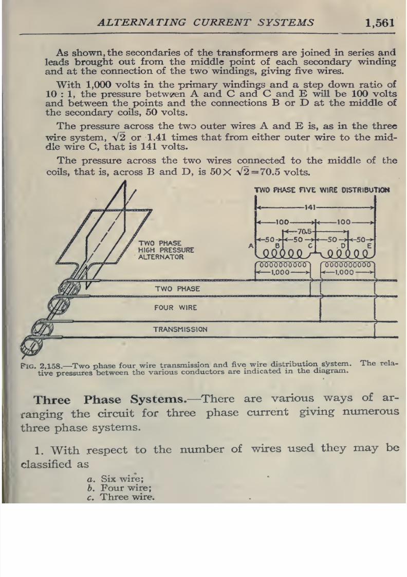
8/20/2019 electrical guide 5.pdf
http://slidepdf.com/reader/full/electrical-guide-5pdf 307/343
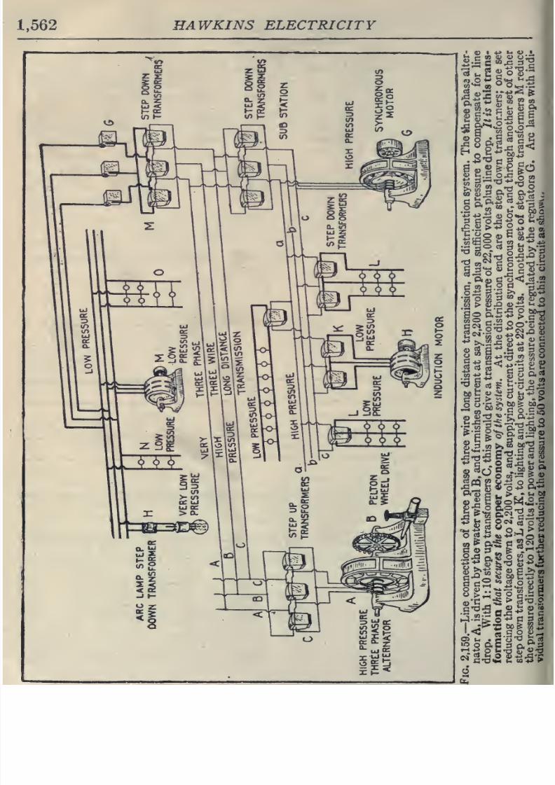
8/20/2019 electrical guide 5.pdf
http://slidepdf.com/reader/full/electrical-guide-5pdf 308/343
1,562
HAWKINS
ELECTRICITY
in
Pi
5;
M
to
_,
'J
O
•t-'
-Pi;
0)
o*^
<u
'A
3
c
o^*e
o
k-'S
.52
go
ft
2
2
^
3
n
«xi
<o*i ^^a
w+j
h §
o ft«
Mm
J5^
h $0^ ft+^ft+^
S-t3£'2
i.<3
«
S
o
2?-^
JO
o
ft a
3
ft
r*
3
6
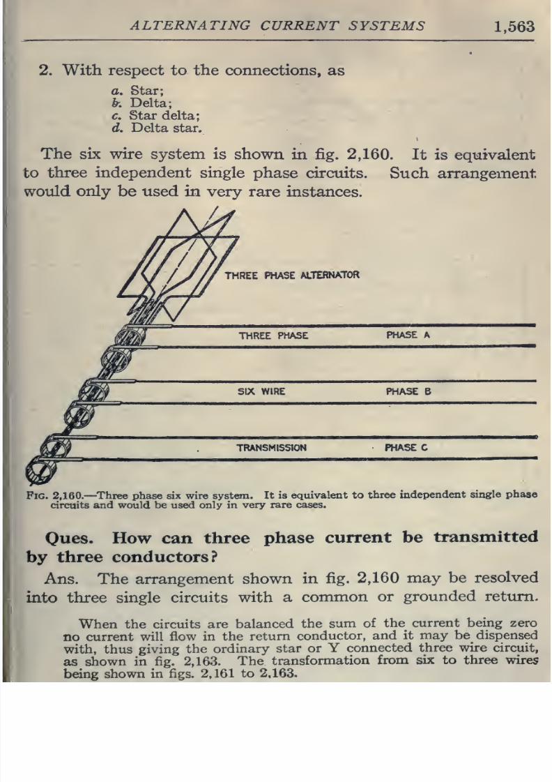
8/20/2019 electrical guide 5.pdf
http://slidepdf.com/reader/full/electrical-guide-5pdf 309/343
ALTERNATING
CURRENT
SYSTEMS
1,563
2.
With
respect
to
the
connections,
as
a.
Star;
k.
Delta;
c.
Star
delta;
d.
Delta star.
The
six
wire
system
is
shown
in
fig.
2,160.
It
is equivalent
to
three independent
single
phase circuits.
Such
arrangement
would
only
be used in
very
rare
instances.
THREE
PHASE
ALTERNATOR
THREE
PHASE
PHASE
A
SIX
WIRE PHASE
B
TRANSMISSION PHASE
C
Fig.
2,160.—Three
phase
six
wire system.
It
is equivalent
to
three
independent
single phase
circuits
and would
be
used
only
in
very
rare cases.
Ques.
How can three
phase
current be
transmitted
by
three
conductors?
Ans.
The
arrangement
shown
in
fig.
2,160
may
be resolved
into
three
single
circuits
with
a
common
or
grounded
return.
When the circuits
are
balanced
the
sum
of
the
current
being
zero
no
current
will
flow in
the
return
conductor,
and it
may
be dispensed
with,
thus
giving
the
ordinary
star
or
Y
connected
three
wire
circuit,
as
shown
in
fig.
2,163.
The
transformation
from six
to
three wires
being
shown in figs. 2,161
to
2,163.
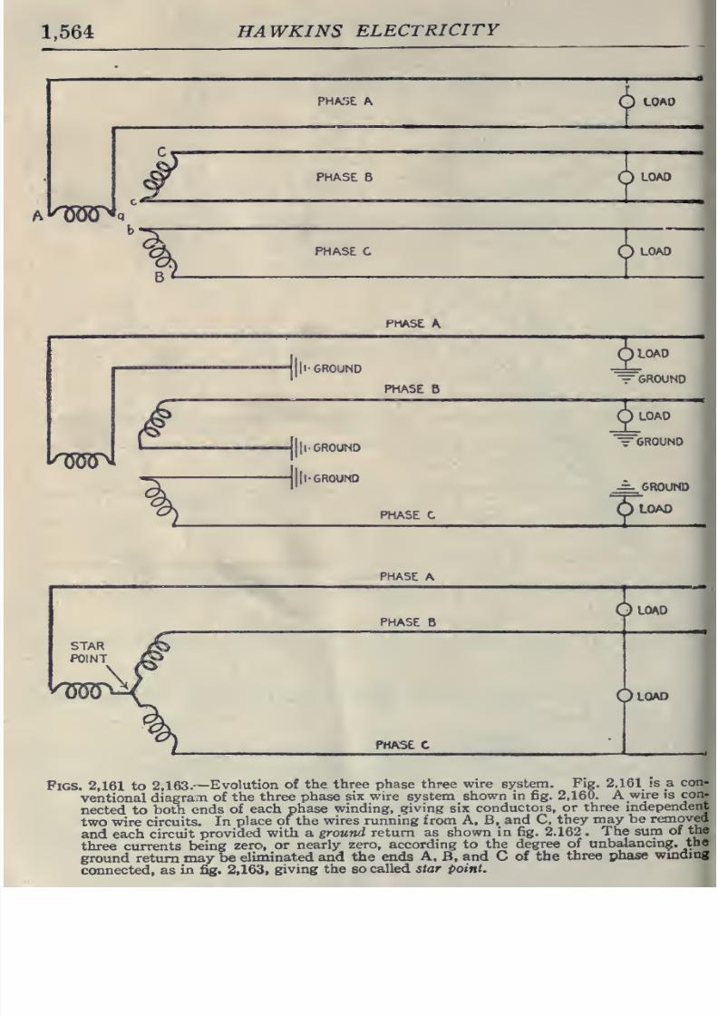
8/20/2019 electrical guide 5.pdf
http://slidepdf.com/reader/full/electrical-guide-5pdf 310/343
1,564
HAWKINS
ELECTRICITY
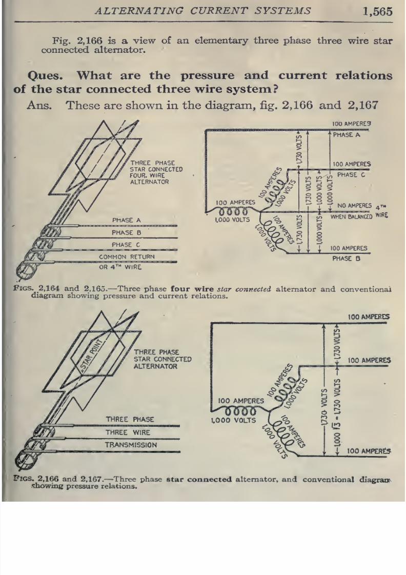
8/20/2019 electrical guide 5.pdf
http://slidepdf.com/reader/full/electrical-guide-5pdf 311/343
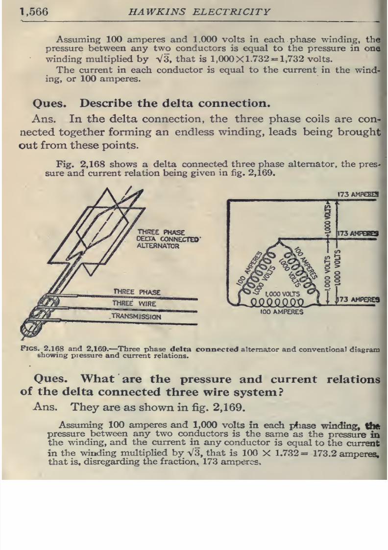
8/20/2019 electrical guide 5.pdf
http://slidepdf.com/reader/full/electrical-guide-5pdf 312/343
1,566
HAWKINS
ELECTRICITY
Assuming
100
amperes
and 1.000
volts
in
each
phase
winding,
the
pressure
between
any
two
conductors
is
equal
to
the pressure
in
one
winding multipHed
by
VS,
that
is
1,000X1.732
=
1,732 volts.
The
current
in
each
conductor
is
equal
to the
current
in the
wind-
ing, or
100
amperes.
Oues.
Describe
the
delta
connection.
Ans.
In
the
delta
connection,
the
three phase
coils
are con-
nected together
forming
an
endless
winding,
leads
being
brought
out
from these points.
Fig.
2,168
shows a
delta
connected
three
phase
alternator,
the
pres'
sure and
current
relation
being
given
in
fig.
2,169.
I73AMF€BE5
THREE
PHASE
OEOA
CONNECTS)'
ALTERNATOR
100
AMPERES
Figs.
2.168
and
2,169.
—Three
phase delta
connected
alternator
and
conventional
diagram
showing
piessure
and
current
relations.
Oues.
What
are the
pressure and
current
relations
of
the
delta
connected
three
wire
system?
Ans.
They
are as
shown
in fig.
2,169.
Assuming 100
amperes
and
1,000
volts
in each
pfiase
winding,
tbtt
pressure
between
any two
conductors
is
the
same
as
the
pressure
in
the
winding,
and
the current
in
any conductor
is equal
to
the
current
in
the winding
multiplied
by
V3,
that
is
100
X
1.732
=
173.2
amperes,
that
is,
disregarding
the fraction,
173 amperes.
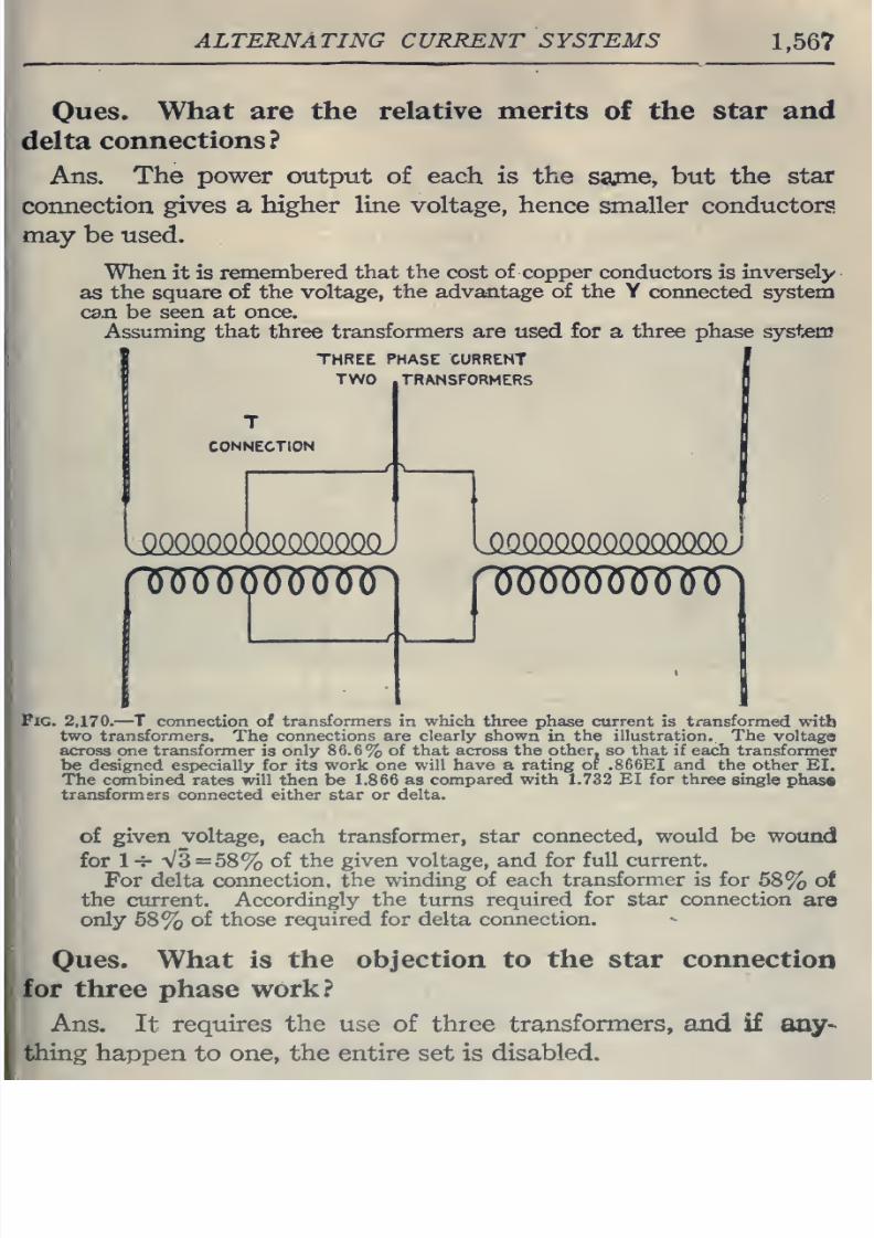
8/20/2019 electrical guide 5.pdf
http://slidepdf.com/reader/full/electrical-guide-5pdf 313/343
ALTERNATING CURRENT
SYSTEMS
1.567
Oues.
What are the relative merits
of
the
star
and
delta
connections?
Ans.
The
power
output of each is the
sajne,
but
the
star
connection
gives
a
higher line voltage,
hence
smaller conductors
may
be
used.
When
it is
remembered
that
the
cost
of
copper
conductors is
Inversely
as
the square of
the voltage,
the
advantage of
the
Y
connected system
can be
seen
at
once.
Assuming
that
three
transformers are
used for a
three
phase
system
1
THREE
PHASE
CURRENT
TWO
TRANSFORMERS
T
CONNECTION
lQQQQaoOQQ.OQQQOOJ
iommooMsmu
nmmmu
y
V
Fig.
2,170,
—
T
connection of
transformers
in
which
three
phase
current
is
transformed
with
two
transformers.
The
connections
are
clearly shown
in
the
illustration.
The
voltage
across
one
transformer
is
only
86.6%
of
that
across
the
other,
so that
if
each
transformer
be designed especially
for
its
work
one
will
have
a
rating
of
.866EI
and the
other
EI.
The
combined
rates will
then
be 1.866
as
compared with 1.732
EI
for
three
single
phas«
transformers
connected either
star
or
delta.
of
given
voltage,
each transformer, star
connected, would be
wound
for
1-7-
V3
=
58%
of
the
given
voltage, and for
full current.
For
delta
connection,
the
winding of each
transformer
is for
58%
of
the current. Accordingly
the turns required
for star connection
axe
only
68%
of
those
required
for
delta connection.
Ques.
What
is
the objection to the star
connection
for three
phase
work?
Ans.
It
requires
the
use
of
three
transformers,
and
if
any-
thing
happen
to
one, the entire
set
is
disabled.
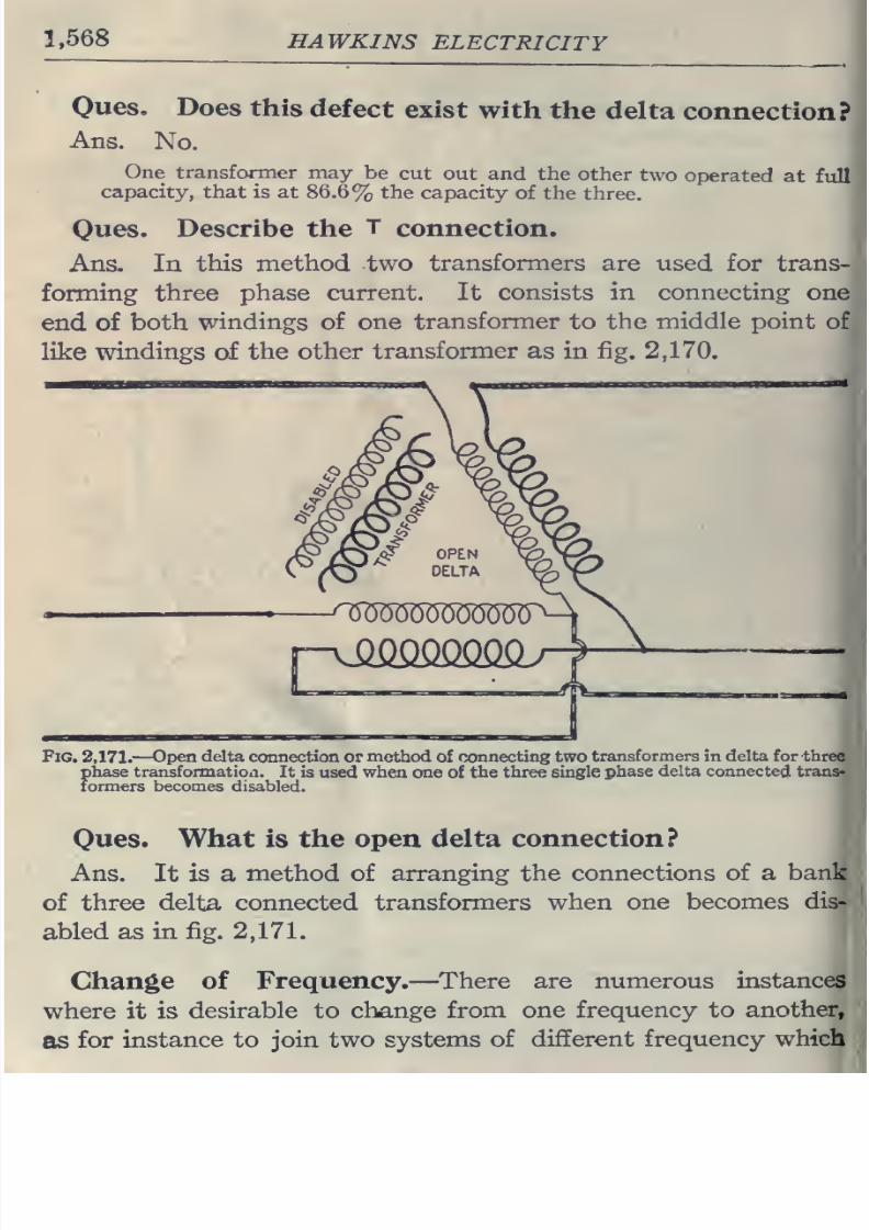
8/20/2019 electrical guide 5.pdf
http://slidepdf.com/reader/full/electrical-guide-5pdf 314/343
1,568
HAWKINS
ELECTRICITY
Ques.
Does
this
defect
exist
with
the
delta
connection?
Ans.
No.
One
transformer may
be
cut
out and
the
other
two
operated
at full
capacity,
that
is
at
86.6%
the capacity
of the
three.
Ones.
Describe
the
T
connection.
Ans.
In
this method
two
transformers
are
used
for
trans-
forming
three
phase
current.
It
consists in
connecting
one
end of
both
windings
of
one
transformer
to
the
middle
point
of
like
windings
of
the other
transformer
as in
fig.
2,170.
Fig. 2,171.
—
Open
delta
connection
or
method
of connecting two
transformers
in
delta
for three
phase
transformation.
It
is used when
one of the
three single
phase
delta
connected
trans-
formers becomes
disabled.
Ones.
What
is
the
open
delta connection?
Ans.
It
is
a
method
of
arranging the
connections
of a
bank
of
three
delta
connected
transformers when
one
becomes
dis-
abled
as
in
fig.
2,171.
Change
of
Frequency.
—
There are
numerous
instances
where
it is
desirable
to
change
from one
frequency to
another,
as
for
instance
to
join two
systems
of
different frequency
which
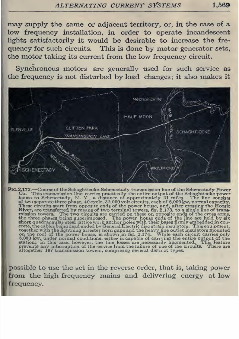
8/20/2019 electrical guide 5.pdf
http://slidepdf.com/reader/full/electrical-guide-5pdf 315/343
ALTERNATING CURRENT
SYSTEMS
1,569
may supply
the
same
or adjacent
territory,
or,
in
the
case
of
a
low frequency
installation,
in
order to
operate
incandescent
lights
satisfactorily
it
would
be
desirable
to
increase
the fre-
quency
for
such
circuits.
This
is
done
by
motor
generator
sets,
the
motor
taking
its current
from
the
low
frequency
circuit.
Synchronous
motors
are generally
used
for
such
service
as
the
frequency
is
not
disturbed
by
load
changes;
it also makes
it
Pig.
2,172.
—Course of the Schaghticoke-Schenectady transmission
line
of
the
Schenectady
Power
Co.
This
transmission line carries practically
the entire output
of
the
Schaghticoke power
];
house
to Schenectady,
N.
Y.,
a
distance
of
approximately 21
miles.
The line
consista
of
two
separate
three
phase,
40cycle,
32,000volt circuits, each of
6,
000
kw.
normal
capacity.
These
circuits
start
from
opposite
ends
of
the
power
house,
and,
after
crossing
the
Hoosic
River,
are
transferred
by
means
of
two
terminal
towers,
fig.
2,173,
to
a
single
fine
of
trans-
mission
towers.
The
tvro
circuits
are carried
on
these
on
opposite ends of
the
cross arms,
the
three
phases
being
superimposed.
The power
house
ends of
the
line
are
held
by
six
short
quadrangular
steel
lattice work
anchor
poles with their bases
firmly
embedded
in
con-
crete,
the
cables being
dead
ended by General
Electric
disc
strain insulators. This equipment,
together
with
the lightning
arrester horn
gaps
and the
heavy
line
outlet
insulators
mounted
on
the
roof
of the
power house,
is
shown
in
fig. 2,174.
While
each
circuit
carries only
6,000 kw.
under
normal conditions,
either
is
capable of
carrying
the
entire
output
of the
station;
in this
case,
however,
the
line
losses
are necessarily
augmented.^
This
feature
prevents any
interruption
of the service from
the
failure of
one
of
the circuits.
There
are
altogether
197
transmission
towers,
comprising
several
distinct
types.
possible
to
use the
set
in
the
reverse
order,
that is,
taking
power
from
the
high
frequency mains
and
delivering
energy
at
low
frequency.
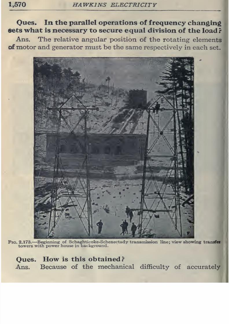
8/20/2019 electrical guide 5.pdf
http://slidepdf.com/reader/full/electrical-guide-5pdf 316/343
1.570
HAWKINS
ELECTRICITY
Ones.
In
the
parallel
operations
of
frequency
changing
sets
what is necessary
to secure equal division
of
the load?
Ans.
The
relative
angular
position
of
the
rotating
elements
of
motor
and
generator
must
be
the
same
respectively
in
each
set.
Pig.
2,173.
—
Beginning
of
Schaghticokt
towers with
power
house
in
background.
y
transmission
lin., 'wing transfet
Ques.
How
is
this
obtained?
Ans.
Because
of
the
mechanical
difficulty
of
accurately
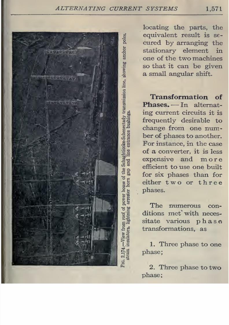
8/20/2019 electrical guide 5.pdf
http://slidepdf.com/reader/full/electrical-guide-5pdf 317/343
ALTERNATING
CURRENT SYSTEMS
1,571
locating
the
parts, the
equivalent
result
is
se-
cured
by
arranging
the
stationary
element
in
one
of
the
two
machines
so
that
it
can
be
given
a small angular
shift.
Transformation
of
Phases.—
In alternat-
ing
current circuits
it is
frequently
desirable
to
change
from
one
num-
ber
of
phases
to
another.
For
instance,
in
the
case
of
a
converter,
it is
less
expensive
and
more
efficient
to use
one
built
for
six phases
than
for
either two
or
three
phases.
The
numerous
con-
ditions
met*
with
neces-
sitate
various
phase
transformations,
as
1.
Three
phase
to
one
phase;
2.
Three
phase
to
two
phase:
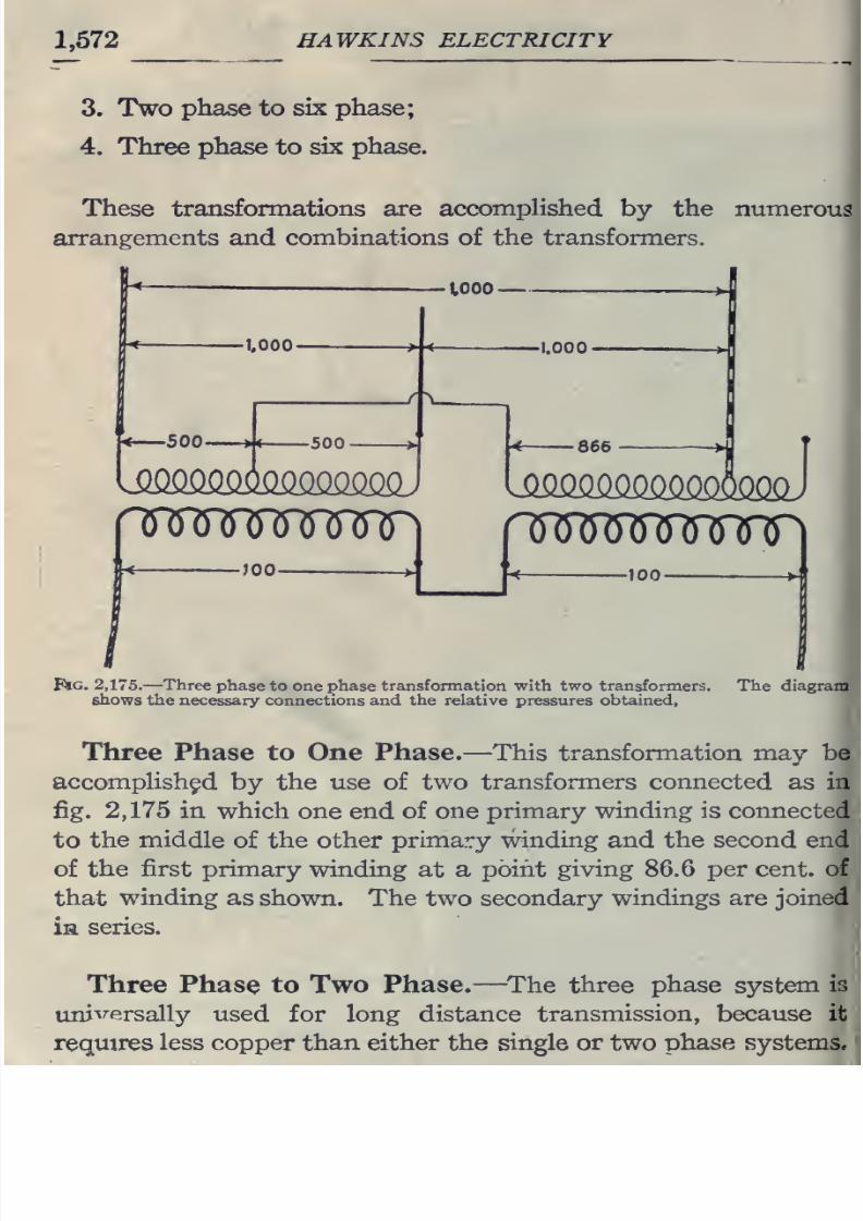
8/20/2019 electrical guide 5.pdf
http://slidepdf.com/reader/full/electrical-guide-5pdf 318/343
1,572
HAWKINS
ELECTRICITY
3. Two
phase
to
six
phase;
4.
Three
phase
to
six
phase.
These transformations
are
accomplished
by
the
numerous
arrangements
and
combinations
of
the
transformers.
tooo-
•1.000-
.500
—
>(
-500
}Qmmmmmi
1.000
I\
866
ismommm
)km)
RRTMiJinnr
;oo-
nnji^JM^nmn
-100-
Pig.
2,175.
—
Three
phase
to one phase
transfonnation
with
two
transformers.
The diagram
shows the necessary
connections
and the
relative pressures
obtained,
Three Phase
to
One
Phase.
—
This transfonnation
may
be
accompHsh^d
by the use of two
transformers connected
as in
fig. 2,175 in
which
one
end
of
one primary
winding
is connected
to
the
middle
of
the
other
primary
winding
and the second end
of
the
first primary
winding
at
a
point
giving 86.6
per
cent,
of
that
winding
as
shown. The two secondary
windings
are
joined
in
series.
Three
Phase
to Two Phase.
—
^The three
phase
system
is
uni^T-ersally
used
for
long
distance
transmission,
because
it
requires
less copper than either the single
or
two
phase
systems.
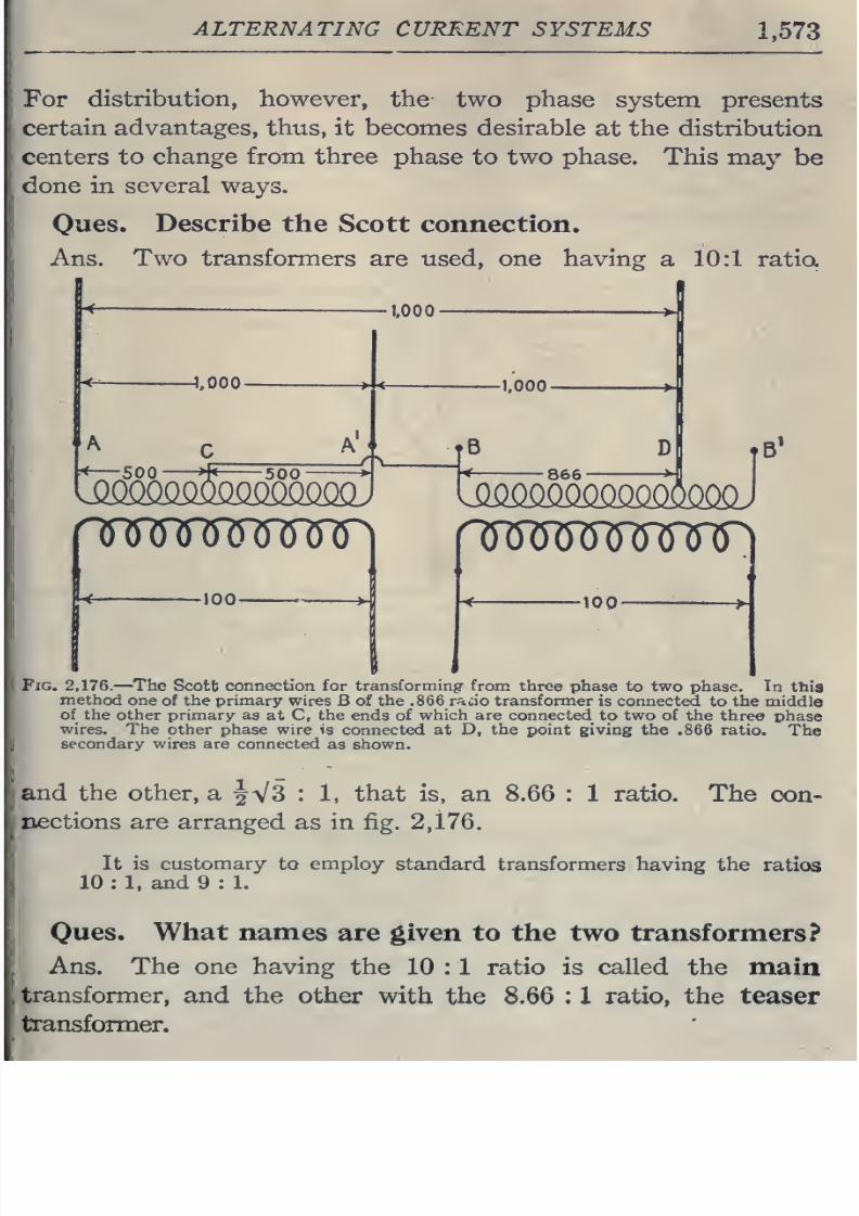
8/20/2019 electrical guide 5.pdf
http://slidepdf.com/reader/full/electrical-guide-5pdf 319/343
ALTERNATING
CURRENT
SYSTEMS
1,573
For
distribution,
however,
the
two
phase
system presents
certain
advantages,
thus,
it becomes
desirable
at the distribution
centers to
change
from
three
phase
to
two
phase.
This
may
be
done
in
several
ways.
Ones.
Describe
the
Scott connection.
Ans.
Two transformers
are
used, one
having
a
10:1
ratio.
1,000-
866
J
100-
FiG. 2,176.
—The
Scott
connection for
transforming
from
three phase
to
two phase.
In
this
method
one
of the primary
wires
B of
the .866
raao
transformer
is connected
to the
middle
of the
other
primary
as
at
C, the
ends
of which are
connected
to
two
of the
three
phase
wires. The
other phase wire is
connected
at D,
the
point giving
the
.866 ratio.
The
secondary
wires are
connected
as
shown.
and
the other, a
^V3
:
1,
that is,
an 8.66
: 1
ratio. The
con-
nections
are
arranged as in
fig.
2,176.
It is
customary
to
employ
standard
transformers
having
the
ratios
10
:
1.
and
9
:
1.
Ques.
What
names
are
given
to
the
two
transformers?
Ans. The one having
the
10
: 1
ratio
is
called
the
main
transformer,
and
the other
with
the 8.66 : 1 ratio, the teaser
transformer.
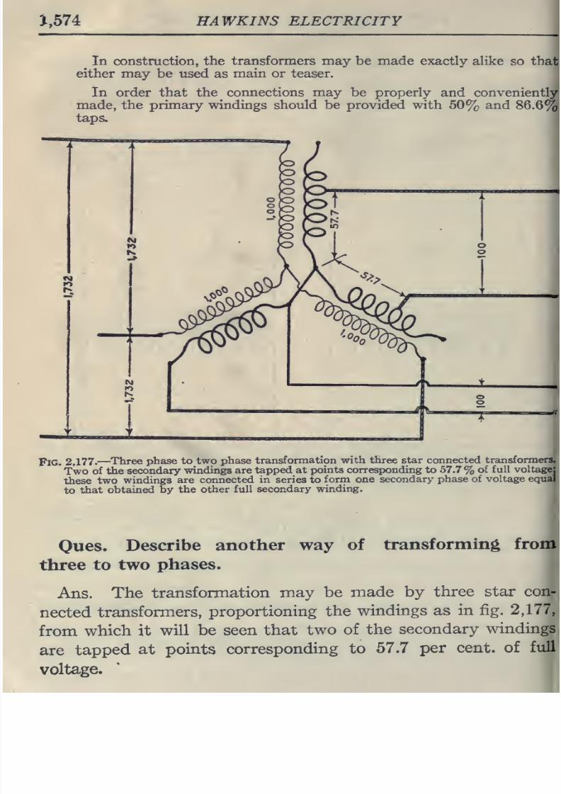
8/20/2019 electrical guide 5.pdf
http://slidepdf.com/reader/full/electrical-guide-5pdf 320/343
J,574
HAWKINS
ELECTRICITY
In construction,
the
transformers may
be
made
exactly
alike
so
that
either
may be used
as
main or teaser.
In order that
the
connections may
be properly
and
conveniently
made,
the
primary windings should be provided with
50%
and
86.6%
taps.
Pig.
2,177.
—Three
phase to
two
phase
transformation
with three star connected
transformers.
Two
of
the
secondary
windings are
tapped
at
points corresponding
to
57.7
%
of
full
voltage:
these
two
windings
are
connected
in
series
to
form
one
secondary phase
of voltage
equal
to
that
obtained
by
the other full
secondary
winding.
Oues.
Describe
another
way
of
three
to
two
phases.
transforming
from
Ans.
The
transformation
may
be
made
by
three
star
con-
nected
transformers,
proportioning the
windings
as
in fig.
2,177,
from
which
it
will be
seen
that
two
of
the
secondary
windings
are
tapped
at points
corresponding
to
57.7
per
cent,
of
full
voltage.
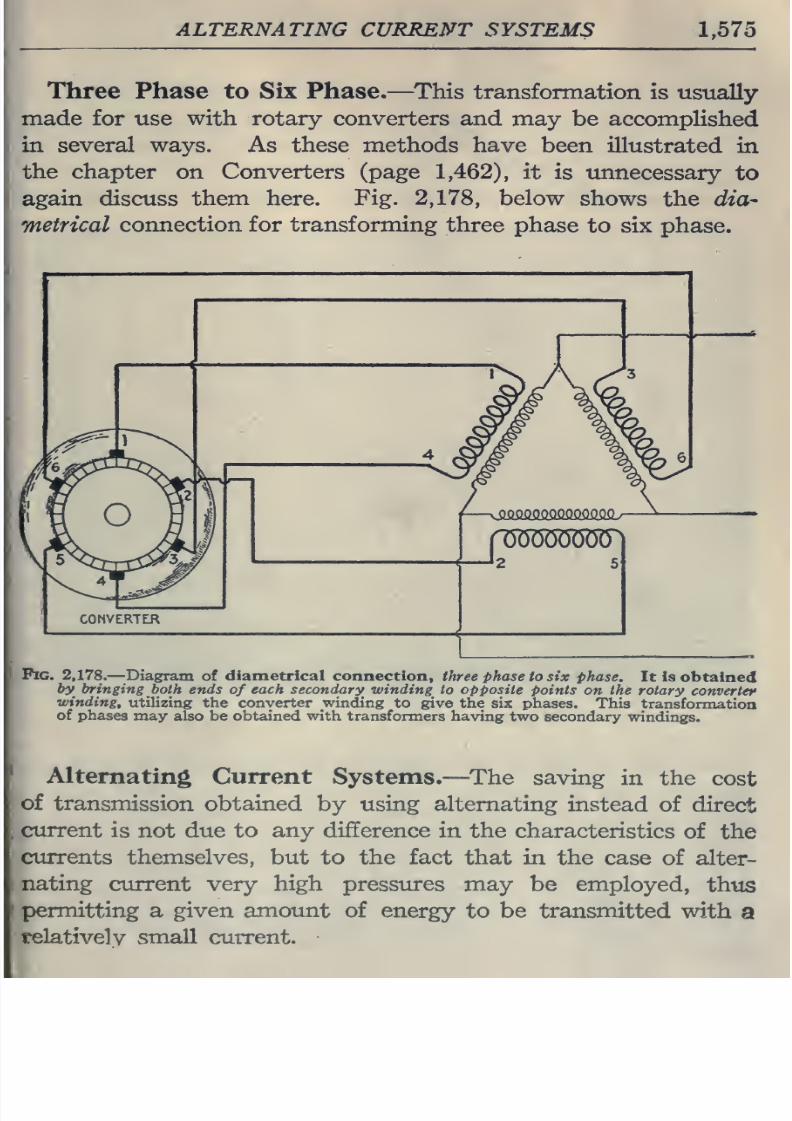
8/20/2019 electrical guide 5.pdf
http://slidepdf.com/reader/full/electrical-guide-5pdf 321/343
ALTERNATING
CURRENT
SYSTEMS
1,575
Three
Phase to
Six Phase.
—
This
transformation
is
usually
made
for use
with
rotary converters
and
may
be
accomplished
in several
ways.
As these methods
have
been illustrated
in
the
chapter
on
Converters
(page
1,462),
it
is
imnecessary
to
again
discuss them here.
Fig.
2,178,
below
shows
the dia^
metrical
connection
for
transforming three
phase
to six
phase.
Fig.
2,178.
—
Diagram
of
diametrical connection,
three
phase
to six
phase.
It
Is
obtained
by bringing
both ends
of
each
secondary -winding to
opposite points
on
the
rotary
converter
winding,
utilizing the
converter
winding
to
give
the
six
phases.
This
transformation
of
phases
may also be obtained
with
transformers
having
two
secondary
windings.
Alternating
Current
Systems.
—
^The
saving
in the
cost
of
transmission obtained
by
using alternating
instead of
direct
current
is
not
due to
any
difference in
the
characteristics
of
the
currents themselves,
but
to the
fact
that
in
the
case
of
alter-
\
nating
current
very
high
pressures
may
be
employed,
thus
I
permitting
a
given
amount
of energy
to be
transmitted
with
a
telativelv
small
current.
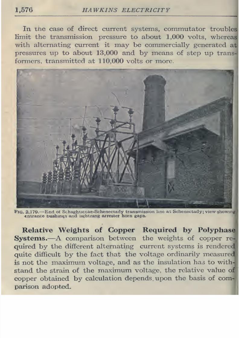
8/20/2019 electrical guide 5.pdf
http://slidepdf.com/reader/full/electrical-guide-5pdf 322/343
1,576
HAWKINS ELECTRICITY
In
the
case of
direct
current
systems,
commutator
troubles
limit
the
transmission pressure
to
about
1,000
volts,
whereas
with
alternating current it
may be
commercially
generated
at
pressures
up
to
about 13,000
and
by means
of
step
up
trans-
fonnors.
transmittor
nt 110,000 vcM^r.
or
mnvc.
Pic. 2,179.—
End
ol
Schaghiicoke-Scheneciady
transmission
line
at
Schenectady;
view
showing
entrance
bushings
and
lightning arrester horn gaps.
Relative
Weights of
Copper
Required
by
Polyphase
Systems.
—A
comparison
between the
weights
of
copper re-
quired
by
the
different
alternating
current
systems
is
renderc
1
quite
difficult
by
the
fact
that
the
voltage
ordinarily
measured
is
not
the
maximum
voltage,
and
as
the
insulation has
to
witli-
stand the
strain
of
the
maximum
voltage,
the relative
value of
copper
obtained by
calculation
depends,
upon
the
basis of
com-
parison adopt-ed.
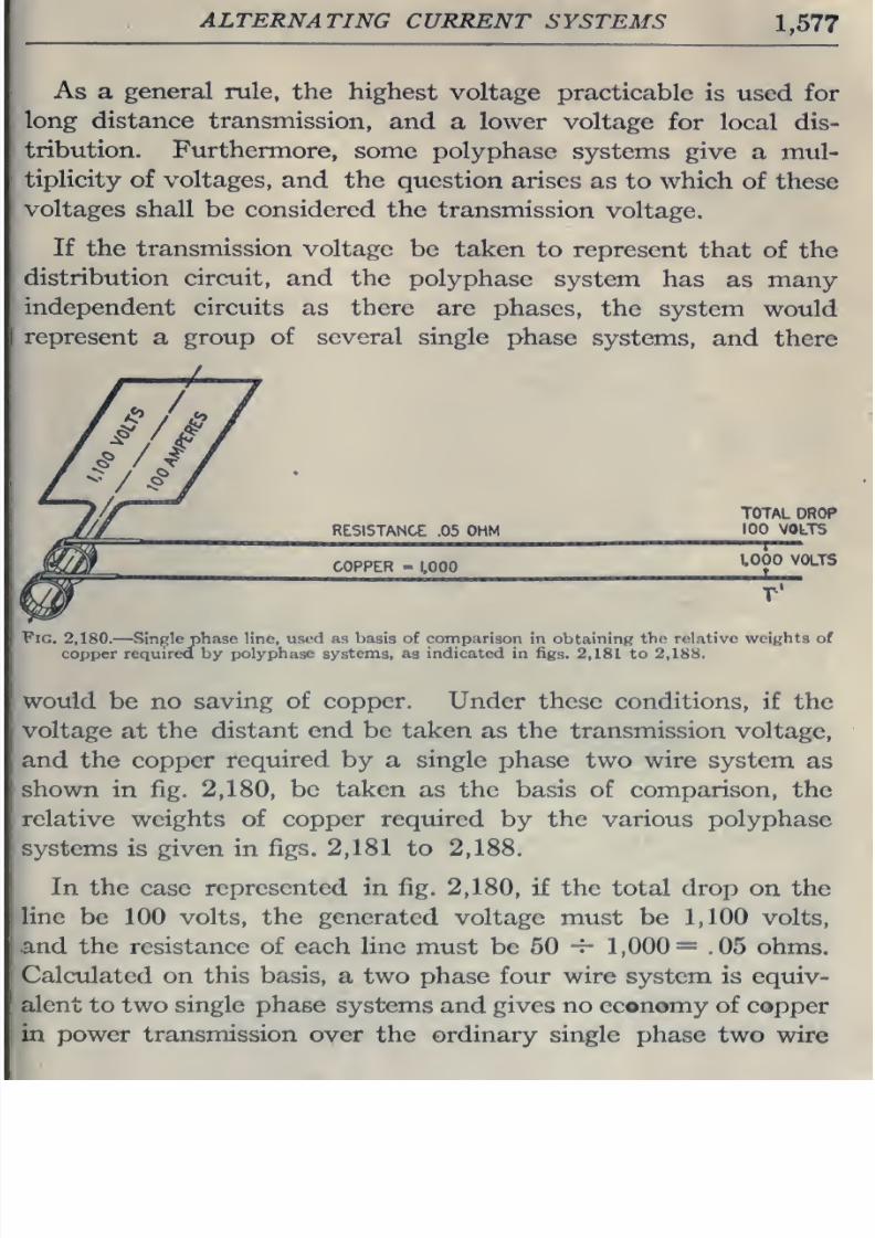
8/20/2019 electrical guide 5.pdf
http://slidepdf.com/reader/full/electrical-guide-5pdf 323/343
ALTERNATING
CURRENT
SYSTEMS
1,577
As
a
general
rule,
the
highest
voltage
practicable
is
used for
long
distance
transmission,
and
a
lower
voltage
for
local
dis-
tribution.
Furthermore,
some
polyphase
systems
give
a
mul-
tiplicity
of
voltages,
and
the
question
arises
as to
which
of
these
voltages
shall
be
considered
the
transmission
voltage.
If
the transmission
voltage
be
taken
to
represent
that
of
the
distribution
circuit,
and
the
polyphase
system
has
as
many
independent
circuits
as there
are
phases,
the
system
would
represent
a
group of
several single
phase
systems,
and
there
RESISTANCE
.05
OHM
TOTAL
DROP
100 VOLTS
COPPER
-
1,000
1000
VOLTS
T'
Fig.
2,180.
—
Single phase
line,
used
as basis of comparison
in
obtaining
the
relative weights of
copper
required
by
polyphase systems, as
indicated
in
figs.
2,181
to
2,188.
would
be
no saving
of copper. Under
these conditions,
if
the
voltage
at
the
distant end be
taken
as
the transmission voltage,
and
the
copper
required
by
a
single
phase
two
wire
system
as
shown
in
fig.
2,180,
be
taken
as the
basis of comparison,
the
relative
weights
of
copper required
by
the
various
polyphase
systems
is given
in
figs.
2,181
to
2,188.
In
the
case
represented
in
fig.
2,180,
if
the total
drop
on the
line
be
100
volts,
the
generated
voltage must be
1,100
volts,
and
the
resistance of
each
line
must
be 60
-5-
1,000=
.05
ohms.
Calculated
on this basis,
a two
phase
four wire system
is
equiv-
alent
to two
single
phase
systems
and
gives
no economy of
copper
in power transmission
over
the
ordinary single phase
two wire
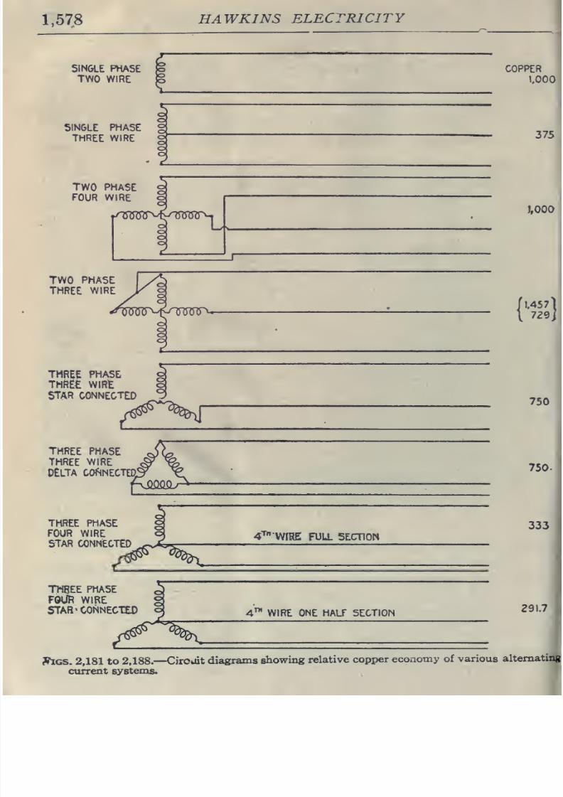
8/20/2019 electrical guide 5.pdf
http://slidepdf.com/reader/full/electrical-guide-5pdf 324/343
1,57.8
HAWKINS
ELECTRICITY
SINGLE
PHASE
TWO
WIRE
COPPER
1000
SINGLE
PHASE
THREE WIRE
TWO
PHASE
FOUR
WIRE
1.000
{'IMl
THREE
PHASE
THRE£
WlRt
STAR CONNECTED
THREE
PHASE
THREE
WIRE
DELTA
COfSNECTED.
750
750.
THREE PHASE
FOUR WIRE
STAR CONNECTED
THBEE
PHASE
FOUft WIRE
STAR
^CONNECTED
SlGS.
2,181
to
2,188.
—
Circuit
diagrams
showing
relative
copper
economy
of
various
current
systems.
altemat
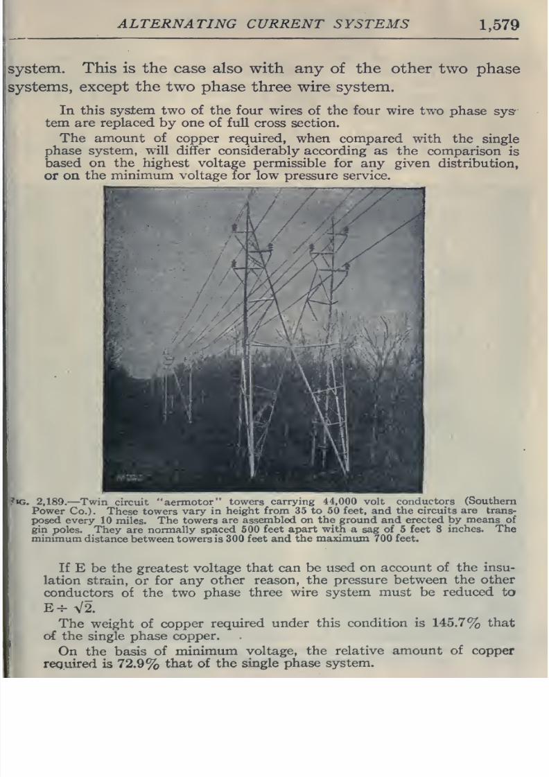
8/20/2019 electrical guide 5.pdf
http://slidepdf.com/reader/full/electrical-guide-5pdf 325/343
ALTERNATING
CURRENT
SYSTEMS
1,579
system.
This
is
the
case
also with any
of
the other
two phase
systems,
except
the
two
phase
three wire
system.
In this system
two
of
the four
wires of the four wire
two
phase
sys'-
tem
are
replaced
by
one
of full
cross section.
The
amount
of
copper
required,
when
compared with
the
single
phase
system,
will
differ considerably
according as the
comparison
is
based
on
the
highest
voltage
permissible for
any given
distribution,
or
on
the
minimum
voltage for low
pressure service.
?«G.
2,189.
—Twin
circuit
aermotor
towers
carrying
44,000
volt
conductors
(Southern
Power
Co.).
These
towers
vary in
height from
35
to
50
feet,
and
the
circuits
are
trans-
EHDsed
every
10
miles.
The
towers
are assembled on
the
ground
and
erected
by
means
of
gin
poles. They
are
normally spaced
500
feet
apart with a
sag
of 5 feet 8
inches.
The
minimum
distance
between
towers is
300 feet and
the
maximum
700
feet.
If
E
be
the
greatest
voltage
that
can be
used
on
account
of
the insu-
lation
strain,
or
for any
other reason,
the pressure
between
the
other
conductors
of
the
two
phase
three
wire
system
must
be
reduced
to
E^
V2.
The
weight of
copper
required
under
this condition is
145.7%
that
of
the
single
phase
copper.
On
the basis
of
minimum
voltage,
the relative
amount
of
copper
required
is
72.9%
that
of the
single
phase system.
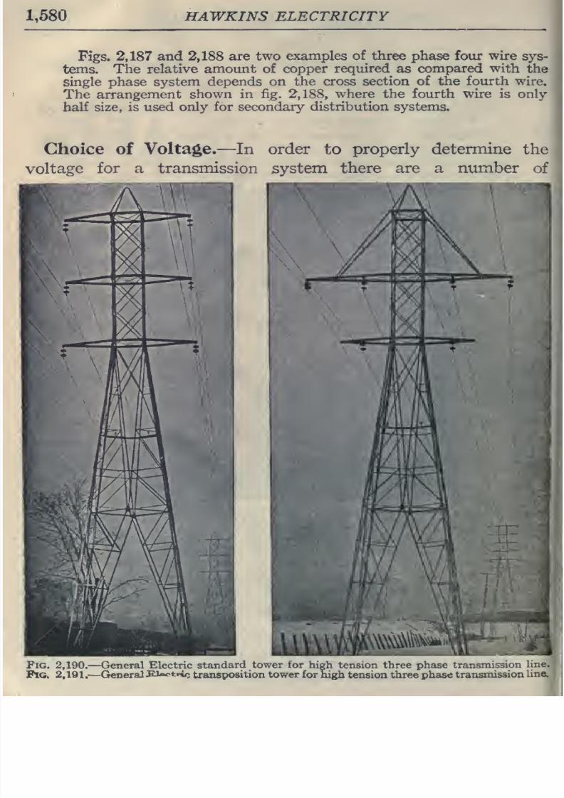
8/20/2019 electrical guide 5.pdf
http://slidepdf.com/reader/full/electrical-guide-5pdf 326/343
1,580
HAWKINS ELECTRICITY
Figs. 2,187
and
2,188
are
two
examples
of
three
phase
four
wire
sys-
tems.
The
relative
amount
of copper
required
as
compared
with
the
single phase system
depends
on
the
cross
section
of
the
fourth
wire.
The
arrangement
shown
in
fig.
2,188,
where the
fourth
wire is only
half
size,
is used
only for secondary
distribution
systems.
Choice of
Voltage.—In
order
to
properly determine
the
voltage
for a transmission
system
there
are a
number
of
Fig.
2,190,
—
General
Electric
standard
tower
for
hi|
Fig. 2,191
.
—
General
ELaotri/;
transposition
tower
for
jh tension three
phase
transmission
line.
aigh
tension
three
phase
transmission
line;
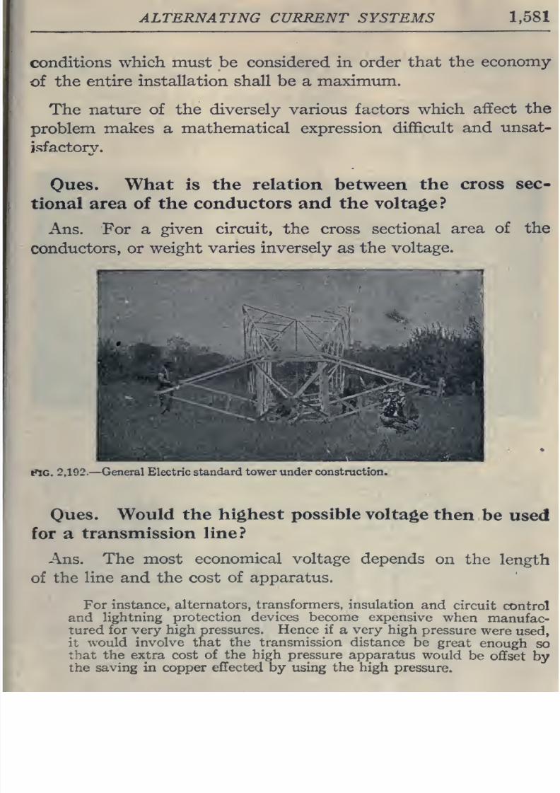
8/20/2019 electrical guide 5.pdf
http://slidepdf.com/reader/full/electrical-guide-5pdf 327/343
ALTERNATING CURRENT SYSTEMS 1,581
conditions
which
must
be
considered in
order
that
the
economy
of
the
entire
installation
shall
be
a
maximum.
The
nature of
the
diversely
various
factors
which
affect
the
problem
makes
a
mathematical expression
difficult
and
unsat-
isfactory.
Oues.
What
is
the relation
between
the
cross sec-
tional area of
the conductors
and
the voltage?
Ans.
For
a
given
circuit,
the
cross
sectional
area
of the
conductors,
or
weight
varies inversely
as
the
voltage.
PIG.
2,192.
—
General
Electric
standard tower
under
construction.
Oues.
Would the
highest possible
voltage
then
be
used
for
a
transmission line?
Ans. The most
economical voltage depends
on the
length
of
the
line
and the
cost
of
apparatus.
For
instance,
alternators,
transformers,
insulation
and
circuit
control
and
lightning
protection
devices become
expensive
when
manufac-
tured
for
very
high
pressures.
Hence
if
a
very
high
pressure
were
used,
it
would
involve that
the
transmission distance
be
great
enough
so
that
the
extra cost
of the
high
pressure
apparatus
would
be
offset
by
the
saving
in copper
effected
by using
the high
pressure.
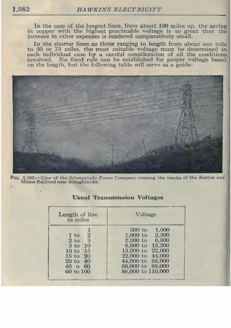
8/20/2019 electrical guide 5.pdf
http://slidepdf.com/reader/full/electrical-guide-5pdf 328/343
1,582
HAWKINS
ELECTRICITY
In
the case of the
longest
lines,
from
about
100
miles
up,
the saving
in
copper
with
the
highest
practicable voltage
is so great
that
the
increase in other
expenses
is
rendered comparatively
small.
In
the
shorter
lines
as
those
ranging in
length
from
about
one
mile
to
50
or
75
miles,
the
most
suitable
voltage
must
be determined
in
each
individual case by
a
careful
consideration
of
all
the conditions
involved.
No
fixed
rule
can be
established
for
proper voltage
based
on
the
length,
but
the
following table
will
serve as
a
guide:
Pig.
2,193.
—
Line
of the
Schenectady
Power Company
crossing
the
tracks
of
the
Boston
anc
Maine Railroad
near
Schaghticoke.
Usual
Transmission
Voltages
Length
of line
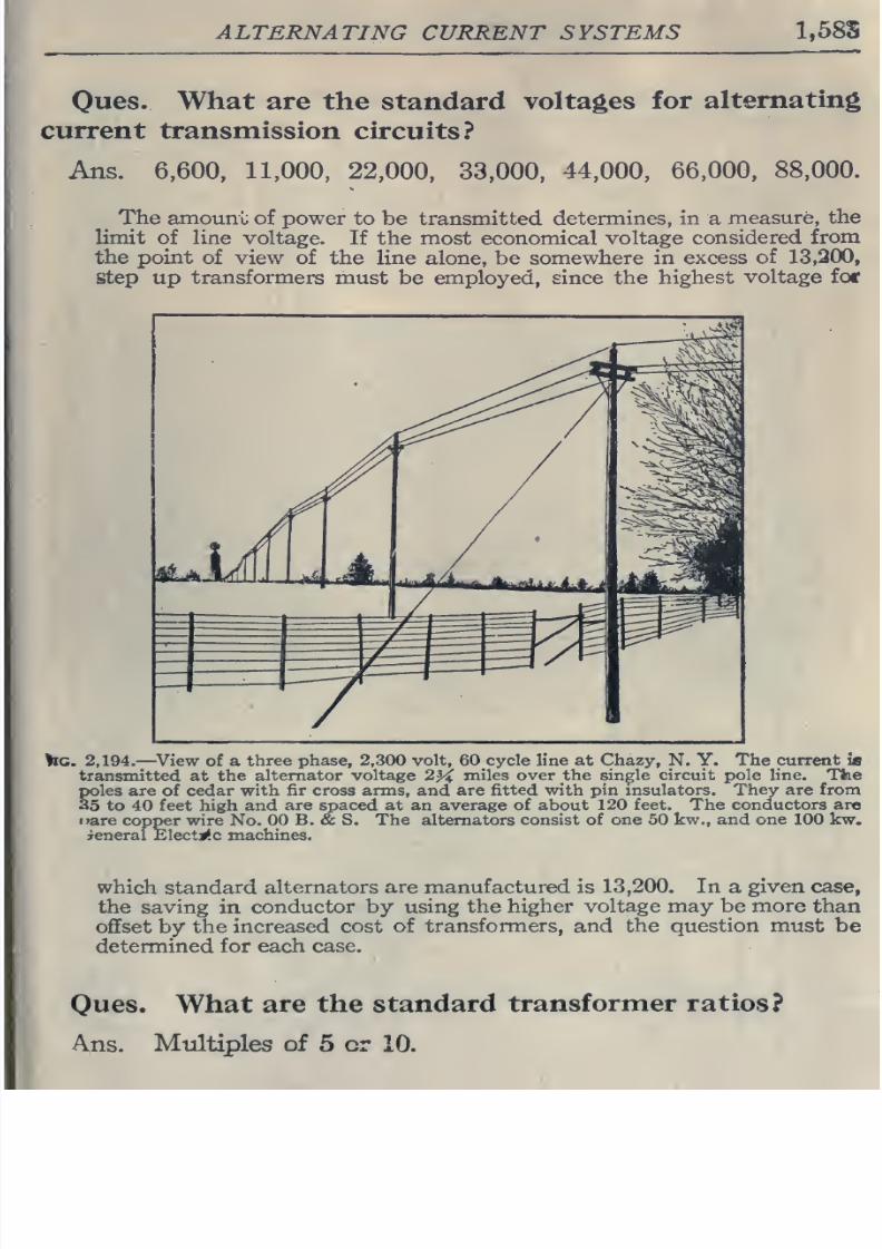
8/20/2019 electrical guide 5.pdf
http://slidepdf.com/reader/full/electrical-guide-5pdf 329/343
ALTERNATING
CURRENT
SYSTEMS
1,58S
Ones.
What are
the
standard
voltages
for
alternating
current
transmission
circuits?
Ans.
6,600,
11,000,
22,000, 33,000,
44,000,
66,000,
88,000.
The amouni;
of power
to be transmitted
determines,
in
a
measure,
the
limit
of
line
voltage.
If the
most economical
voltage
considered
from
the
point
of view
of
the line
alone,
be
somewhere in
excess
of
13,200,
step
up
transformers
must
be
employed, since the
highest
voltage for
>IC.
2,194.
—
^View of
a
three phase, 2,300
volt,
60
cycle
line
at
Chazy,
N.
Y.
The
current
ifl
transmitted
at the
alternator voltage
2^
miles
over the
single
circuit pole line.
The
poles are
of
cedar
with fir
cross
arms,
and are
fitted
with pin
msulators. They
are
from
35
to 40 feet high and
are
spaced
at an average of
about 120 feet. The
conductors are
i»are
copper wire
No.
00 B.
&
S.
The
alternators
consist of
one
50
kw., and one 100 kw.
jeneral Elective machines.
which standard
alternators are
manufactured is 13,200.
In
a
given
the saving
in
conductor by
using the
higher
voltage may
be
more
than
offset
by the
increased cost
of transformers, and
the
question
must
be
determined
for
each
case.
I
Ques.
What
are
the
standard
transformer ratios?
Ans. Multiples
of
5
or 10.
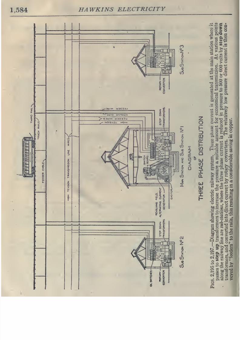
8/20/2019 electrical guide 5.pdf
http://slidepdf.com/reader/full/electrical-guide-5pdf 330/343
1,584
HAWKINS
ELECTRICITY
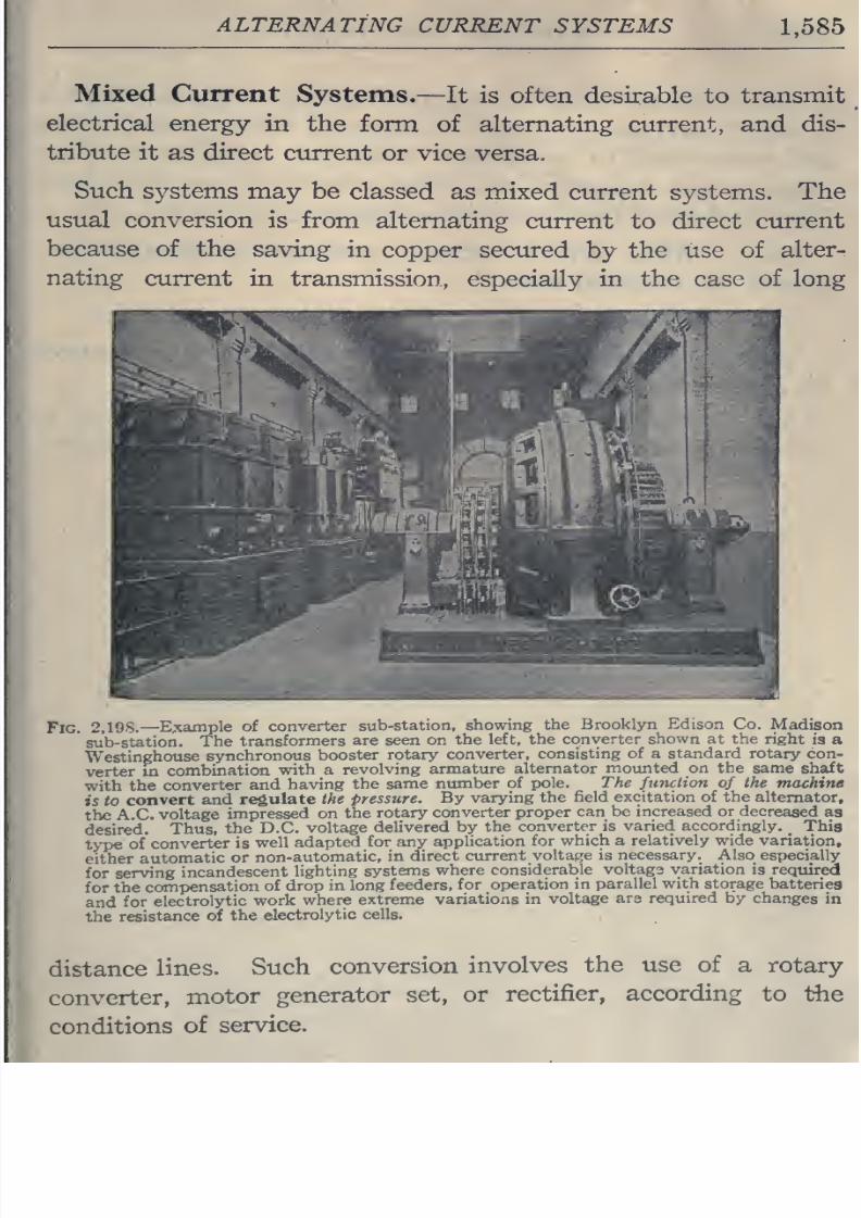
8/20/2019 electrical guide 5.pdf
http://slidepdf.com/reader/full/electrical-guide-5pdf 331/343
ALTERNATING
CURRENT
SYSTEMS
1,585
Mixed
Current
Systems.
—
It
is
often
desirable
to
transmit
electrical
energy
in
the
form
of
alternating
current,
and
dis-
tribute
it as
direct
current
or vice versa.
Such
systems
may
be
classed as
mixed
current systems.
The
usual conversion
is from
alternating
current
to
direct
current
because
of the saving
in
copper secured
by
the use of
alter-
nating
current in
transmission,
especially
in the
case
of long
^#^i
^^i
8/20/2019 electrical guide 5.pdf
http://slidepdf.com/reader/full/electrical-guide-5pdf 332/343
1,586
HAWKINS
ELECTRICITY
The
suburban
trolley
forms
a
good
example of
a
mixed
system,
in
which
alternating
current is
generated
at
the
central
station
and
transmitted
to
substations,
where it
is
transformed
to
lo\\'
pressure,
and
converted
into
direct
current
for
use
on
the
line,
Fig.
2,195
shows
the
interior
of
a
sub-station of
this
kind.
Ones.
What
direct
current
pressure
is
usually
em-
ployed
on
traction
lines?
Ans.
500
volts.
Oues.
Mention
another
important
service
performed
by
a
mixed
system.
Ans.
If the
generator
furnish
alternating
current it must
be
converted
into
direct
current
in
order
to
charge
storage
batteries.

8/20/2019 electrical guide 5.pdf
http://slidepdf.com/reader/full/electrical-guide-5pdf 333/343
8/20/2019 electrical guide 5.pdf
http://slidepdf.com/reader/full/electrical-guide-5pdf 334/343

8/20/2019 electrical guide 5.pdf
http://slidepdf.com/reader/full/electrical-guide-5pdf 335/343
8/20/2019 electrical guide 5.pdf
http://slidepdf.com/reader/full/electrical-guide-5pdf 336/343

8/20/2019 electrical guide 5.pdf
http://slidepdf.com/reader/full/electrical-guide-5pdf 337/343
8/20/2019 electrical guide 5.pdf
http://slidepdf.com/reader/full/electrical-guide-5pdf 338/343

8/20/2019 electrical guide 5.pdf
http://slidepdf.com/reader/full/electrical-guide-5pdf 339/343
8/20/2019 electrical guide 5.pdf
http://slidepdf.com/reader/full/electrical-guide-5pdf 340/343
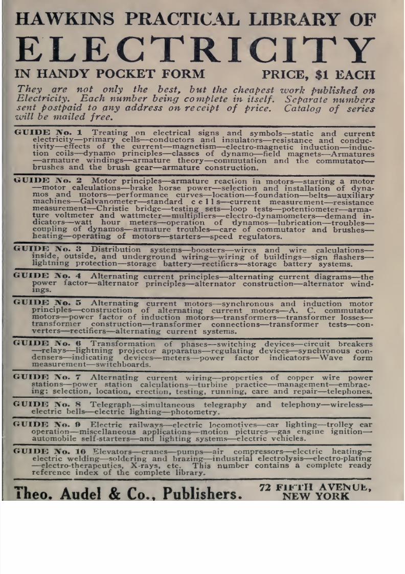
8/20/2019 electrical guide 5.pdf
http://slidepdf.com/reader/full/electrical-guide-5pdf 341/343
HAWKINS
PRACTICAL
LIBRARY
OF
ELECTRICITY
IN HANDY
FORM
PRICE,
$1
EACH
They
are
not
only
the
best,
hut
the
cheapest
work
published
on
Electricity.
Each number
being
complete
in
itself. Separate
numbers
sent
postpaid to any
address
on
receipt
of
price.
Catalog
of
series
will
be mailed
free.
GUIDE
]Vo.
1
Treating
on
electrical signs
and
symbols
—static
and
current
electricity
—
primary
cells
—
conductors
and
insulators
—
resistance
and
conduc-
tivity
—
effects of
the current
—
magnetism
—
electro-magnetic
induction
—
induc-
tion
coils—
dynamo
principles
—
classes
of dynamo
—field magnets
—
Armatures
—
armature windings
—armature theory
—
commutation
and the
commutator
brushes
and
the
brush
gear
—
armature
construction.
guide: IVo.
2
Motor
principles
—
armature
reaction
in motors
—
starting
a motor
—motor
calculations
—
brake
horse
power
—selection
and
installation of
dyna-
mos
and
motors
—
performance
curves—location
—
foundation—
belts
—
auxiliary
machines
—
Galvanometer
—standard
cell
s—current
measurement
—resistance
measurement
—Christie
bridge
—
testing
^
sets
—loop
tests
—
potentiometer
—
arma-
ture
voltmeter and
wattmeter—
multipliers
—electro-dynamometers
—
demand in-
dicators
—
watt
hour
meters
—
operation
of
dynamos
—
lubrication
—troubles
coupling
of
dynamos
—armature
troubles
—
care of
commutator
and
brushes
heating
—operating
of
motors
—
starters—
speed
regulators.
GUIDE
No.
3
Distribution
systems
—
boosters
—
wires
and wire
calculations
inside,
outside,
and
underground
wiring
—
wiring
of
buildings
—
sign
flashers
lightning pr
otection
—
storage battery
—
rectifiers
—
storage battery systems.
GUIDE
IVo.
4 Alternating
current principles
—
alternating
current
diagrams
—
the
power
factor
—
alternator
principles
—
alternator construction—
alternator
wind-
ings.
GUIDE
No.
5
Alternating
current
motors
—
synchronous
and induction
motor
principles
—
construction
of
alternating
current
motors
—A. C.
commutator
motors
—
power
factor
of
induction
motors
—
transformers
—
transformer
losses
transformer
construction
—transformer
connections
—transformer
tests
—
con-
verters—
rectifiers
—
alternating
current
systems.
GUIDE
No.
tt
Transformation
of
phases
—
switching
devices
—
circuit
breakers
—
relays—
lightning
projector
apparatus
—
regulating
devices
—
synchronous
con-
densers
—
indicating
devices
—
meters
—
power
factor
indicators—
Wave form
measurement
—
switchboards.
GUIDE
No.
7 Alternating
current wiring
—
properties
of
copper wire
power
stations
—
power
station
calculations
—
turbine
practice
—
management
—
embrac-
ing:
selection,
location,
erection,
testing,
running,
care
and repair—
telephones.
GUIDE
No.
8
Telegraph
—
simultaneous
telegraphy and
telephony
—wireless
electric bells
—
electric
lighting
—
photometry.
GUIDE
No.
Electric
railways
—
electric
locomotives
—
car
lighting
—
trolley
car
operation
—miscellaneous
applications—
motion
pictures
—
gas engine
ignition
—
automobile
self-starters
—
and
lighting
systems
—
electric
vehicles.
GUIDE
No.
10 Elevators
—
cranes
—
pumps
—
air compressors
—
electric
heating
electric
welding
—soldering
and
brazing
—
industrial
electrolysis
—
electro-plating
—electro-therapeutics,
X-rays,
etc.
This
number
contains
a
complete
ready
reference
index
of
the complete
library.
'•'1
A
J
1
O
r* D Ll«
L
72
FIFTH
AVENUE,
iheo.
Audel
&
to.
rublishers.
new
ork
8/20/2019 electrical guide 5.pdf
http://slidepdf.com/reader/full/electrical-guide-5pdf 342/343

8/20/2019 electrical guide 5.pdf
http://slidepdf.com/reader/full/electrical-guide-5pdf 343/343