Embed Size (px)
Citation preview

www.exxelia.com
July 03 2018
Electrical equipment evolution in civil aeronautics :
Designer point of viewEXXELIA / SAFRAN
Magnetic components / Converters
2
Summary
IntroductionElectrical energy in aircraft : history, how much and why
More electrical aircaft : what does it mean, consequences
Converter designer side and point of viewsome information about soft switching
influence about transformer drawbacks on soft switching
contribution of digital technologies to soft switching
Magnetic component designer side and point of viewWhat is an « optimized » design?
3 examples of designs in detail : 12 pulse, disymmetric ½ bridge, 2 bridges 180° phase shift
other examples
Conclusionsconverter side
magnetic side

3
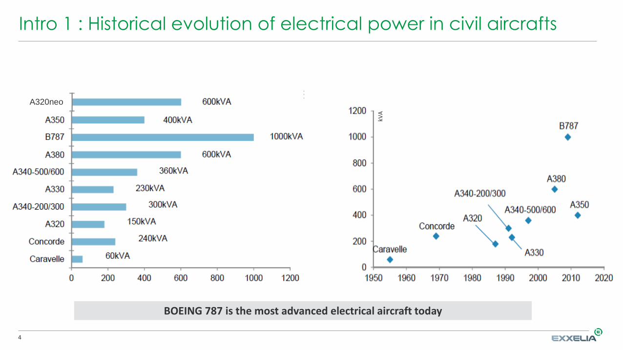
Intro 1 : Historical evolution of electrical power in civil aircrafts
4
Intro 1 : Historical evolution of electrical power in civil aircrafts
A320neo
A320neo
BOEING 787 is the most advanced electrical aircraft today
kVA

5
Intro 2 : Electrical power, how much and why
Nowadays, on average, only 15% of energy in an aircraft is electrical --> potential increase is huge!
Distribution evolution : Pneumatics / Hydraulics / Electrics Why « More Electrical » ?
+
-
Mo
reLe
ss
ReliabilityAvailabilityPayload
Maintenance & repairMass EnergyFuel
6
Intro 3 : More electrical aircraft? (1/2)
More electric aircraft. What does it mean?
more electric functions and power ==> more equipments and converters
==> electrical network become more complicated
The weight cannot increase as much as the electrical power :==> 1 : Power on volume/weight ratios have to increase
==> 2 : Equipements are used differently at different moments of the flight/mission :
(sharing of equipments)
Consequences for electric equipments (1/2) :
Customer needs become more and more specifics
More and more design constraints
7
Intro 4 : More electrical aircraft? (2/2)
Consequences for electrical equipments (2/2)- converter efficiency has to increase (> 95% typical)
- functioning with innovative modes : new converter topologies
- increase of operating frequencies (also with SiC and GaN technologies)
- increase of operating temperatures : environment and internal heatings
Challenges to take for (magnetic) component designers :Thermal : heating / warm up control,
Power Electronics : converter functioning understanding
Magnetism : better control of component drawbacks and limits
new design methods. Ex : leakage inductance
Magnetic component functioning is more and more
connected with and dependent of Power Electronics
Converter designer side and point of view

9
Convert : Wide BandGap switches – hard-switching converters
For the same die (puce) size, conduction losses and some of switching losses decrease significantly
=> possible gain on efficiency
Opportunity to save volume/weight by increasing the switching frequency for equivalent losses
=> possible savings on the input filter
Limits of this approach
1 EMI common-mode emissions may increase, due to higher dv/dt applied
2 Sensitivity of some WBG components to spikes due to the switching transients (e.g. gate spikes) => layout between Driver and Transistor is critical in this case
3 Losses linked to the layout and to magnetic components drawbacks increase
4 AC winding losses increase in magnetic components :
may be the biggest challenge
Knowledge + experience on high frequency magnetic design needed
Calculation/Simulation/Measurement of losses and internal temperature needed

10
Convert : Wide Bandgap switches – soft-switching topologies(1/2)
Main interests of the soft-switching topologies :
1 minimization of the switching losses
optimum if soft-switching for all primary and secondary devices
2 limitation of the dv/dt (for ZVS converters) :
Good for EMI (especially common-mode emissions)
Minimization of spikes due to the switching transients
3 Potential limitation of the di/dt (e.g. LLC converter)
=> rectifier recovery losses lowered
Limitations
1 Soft-switching conditions can limit indirectly the optimum working range of the converter
2 RMS currents often increase compared to hard-switching at the same operating point
3 Some of the soft-switching topologies need to be controlled using variable frequency
11
Convert : Wide Bandgap switches – soft-switching topologies (2/2)
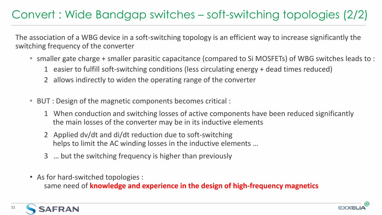
The association of a WBG device in a soft-switching topology is an efficient way to increase significantly the switching frequency of the converter
• smaller gate charge + smaller parasitic capacitance (compared to Si MOSFETs) of WBG switches leads to :
1 easier to fulfill soft-switching conditions (less circulating energy + dead times reduced)
2 allows indirectly to widen the operating range of the converter
• BUT : Design of the magnetic components becomes critical :
1 When conduction and switching losses of active components have been reduced significantlythe main losses of the converter may be in its inductive elements
2 Applied dv/dt and di/dt reduction due to soft-switchinghelps to limit the AC winding losses in the inductive elements …
3 … but the switching frequency is higher than previously
• As for hard-switched topologies :same need of knowledge and experience in the design of high-frequency magnetics

12
Convert : WideBand GaP, a new way to design power converters
WBG makes it possible to increase 10 times the switching frequencyfor the same losses with SiC/GaN.
Easy to implement on one specific operating point
with appropriate existing topologies (LLC, DAB, Forward active-clamp)
BUT
Most of industrial applications need to cover a wide range of operating points(variables : input voltage, output power, frequency, etc)
So the true challenge is :
How to keep soft switching over the whole operating range?

13
Convert : Transformer plays a key part, ReX on DAB converter
• In more and more isolated DC/DC topologies (DAB, PSB) , the problem :
« raising switching frequency + soft-switching (ZVS) over a wide range of operation points »
has a solution only with defining a complex transformer with many constraints
Typical requirements:Power dynamic of [1 to 3]Regulated output dynamic of [1 to 3]
At each operating point, the conditions to stay in soft-switching will lead to
different constraints on transformer (Lk, Cp)
14
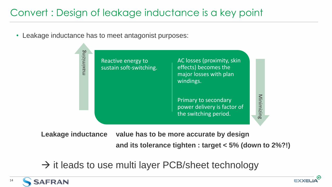
Convert : Design of leakage inductance is a key point
Reactive energy to sustain soft-switching.
AC losses (proximity, skin effects) becomes the major losses with plan windings.
Primary to secondarypower delivery is factor of the switching period.
max
imiz
ing
Min
imizin
g
• Leakage inductance has to meet antagonist purposes:
Leakage inductance value has to be more accurate by design
and its tolerance tighten : target < 5% (down to 2%?!)
it leads to use multi layer PCB/sheet technology

15
Convert : The key role of inter-winding capacitance
switchingfrequency increase
Deadtime has to decrease
dV/dt increases
Inter-windingcapacitance has to decrease
• This capacitance decrease is not compliant with the minimization of AC losses with standard planartransformer interleaving technics.
• Capacitance can have an influence on dead time
• Energy stored in the inter-windings capacitance has to be taken into account in the soft-switching!

16
Convert : What about transformer turn ratio?
• Eddy currents & skin effect force to cut plan layer into a matrix of inter-connected thin tracksthat lead to:
1. Additional constraints on the PCB of the planar transformer that can’t be met
except with advanced PCB assembly technologies
1. Number of vias increases and can’t be ignored in the Finite Element modelling
to get a correct evaluation of the leakage inductance.
2. Window factor is less optimized for a given current density.
• Increase the number of tracks doesn’t help to decrease the inter-winding capacitance.
• Therefore a good practical rule is :
Soft switching at high frequency is only achievable
with low turn (ratio) for the transformer

17
Convert : How wide voltage range give a headache!
• Sustain soft-switching for higher voltage means higher LI² to manage higher CV².
• 2 paths are given :
• Possible mitigations:
Adapt the reactive energy and the switching frequency on each operating point
Use variable permeability material to shape leakage inductance
Consequences for the converter :
1 needs a non-linear parameter variant system : magnetic material of magnetics?
2 requires more robust control/command/regulation (pb of dynamic behaviour)
Increase circulatingcurrent
Higher rms current
Higher conduction losses
Increase leakageinductance
Lower power supplied
Lower sw. frequency
18
Convert : Move from one single variable to multi-variable control
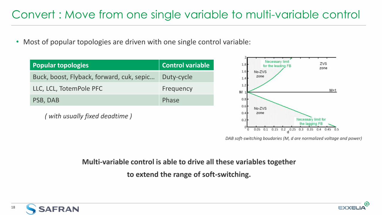
• Most of popular topologies are driven with one single control variable:
( with usually fixed deadtime )
DAB soft-switching boudaries (M, d are normalized voltage and power)
Popular topologies Control variable
Buck, boost, Flyback, forward, cuk, sepic… Duty-cycle
LLC, LCL, TotemPole PFC Frequency
PSB, DAB Phase
Multi-variable control is able to drive all these variables together
to extend the range of soft-switching.

19
Convert : How digital control can decrease transformer constraints
• Multi-variable control is easily implementable in an FPGA or MCU:
• One command variable to regulate output voltage
• One command variable to perform soft-switching and minimize reactive energy.
• Command on duty cycle to cancel DC current.
• Switching Frequency to perform soft-switching and supply minimum power required.
• Deadtime to perform soft-switching
• Management of trajectories between operating points to avoid magnetic saturation.
• Leakage inductance value is estimated with non-linear parameter observer.
• Digital robust controller can provide good stability margin of the closed-loop system with large parameter variations of the converter.
Trade-off for the transformer is extended to the control part

20
Convert : Transformer of the future for high frequency purpose
• Current density increased in the conductors thanks to innovative integration and layer cooling
• Magnetic material improved with variable « non-linear » permeability
• New geometries of cores to ease PCB constraints (exp : Matrix transformer)
• End of opposition between decreasing leakage inductance and parasitic capacitance
• Repeatability of drawbacks improved
Magnetic component designer side and point of view

22
Mag comp : What is an « optimised » design? (1/2)
Identify the smallest size (weight / volume) able to transfer power trade-off between :
Too small excessive internal heating
Too big too heavy and/or too large
It is mandatory to be able to identify configurations of use which lead to the highest constraints
They vary from one converter to the other : I/Vmin/max? Pmin/max? Fmin/max? Tmin/max?
Is it possible to identify them without understanding how the converter functions? NO
It is mandatory to know wave forms I/V inside the component
Could the magnetic designer know them without calculating them? VERY DIFFICULT
ConclusionMagnetic components designers have to understand (at least partially) how the converter works.
They must be able to calculate wave forms in all configuration of use
Power Electronics
Why? Because in aviation, 1g = 1€
big security margins, IT’S OVER

23
Mag comp : What is an « optimised » design? (2/2)
Taking into account 3 types of variations :1 : Excitation (I and/or V) 2 : Frequency 3 : Temperature
4 (+1) design criteria :Saturation, copper losses, iron losses, heating … + manufacturing (raw materials and process)
Need of behaviour models reliable and accurate (!?) for :Induction : nonlinearities, main and secondary hysteresis loop
Copper losses : DC resistances and Eddy currents
Iron losses : Are circuit/material manufacturer formulas sufficient?
Internal heating : - thermal model of magnetic component?
- Rth variations depending on losses and environment temperature
- taking account of cooling : conduction, convection, radiation
Challenge : to know limits of our (these) behaviour models!!
Electromagnetism + Thermics

24
Mag comp Ex 1 : 12 pulse auto-transfo + interphase reactor (Safran)
Application : rectifier 115/230Vrms 3ph / 270/540Vdc low harmonics3 stage converter : auto transformer + 12 diode bridge rectifiers + 2 interphase reactors
schematics operating principle :
To respect the vectorial diagram
hard to analyze and understand analytic calculations!

25
Mag comp Ex 1 : 12 pulse auto-transfo + interphase reactor (Safran)
4 steps to design the 2 magnetic components :
Step 1 : - understanding the scientific (IEEE) publications …
- … including partial recalculations (to correct errors!)
- understanding the 2 component functioning + all interactions between all components
for ex : unbalance current between interphase reactor coils
Step 2 : derive a design method for the 2 components including the 4 (+1) aspects
- magnetic : define saturation level after excitation wave forms analysis
- electrical to be able to evaluate copper and iron losses
- thermal : which behaviour model?
- mechanical after evaluating volume and weight (shocks, vibrations)
- and industrial with raw materials and manufacturing process
26
Mag comp Ex 1 : 12 pulse auto-transfo + interphase reactor (Safran)
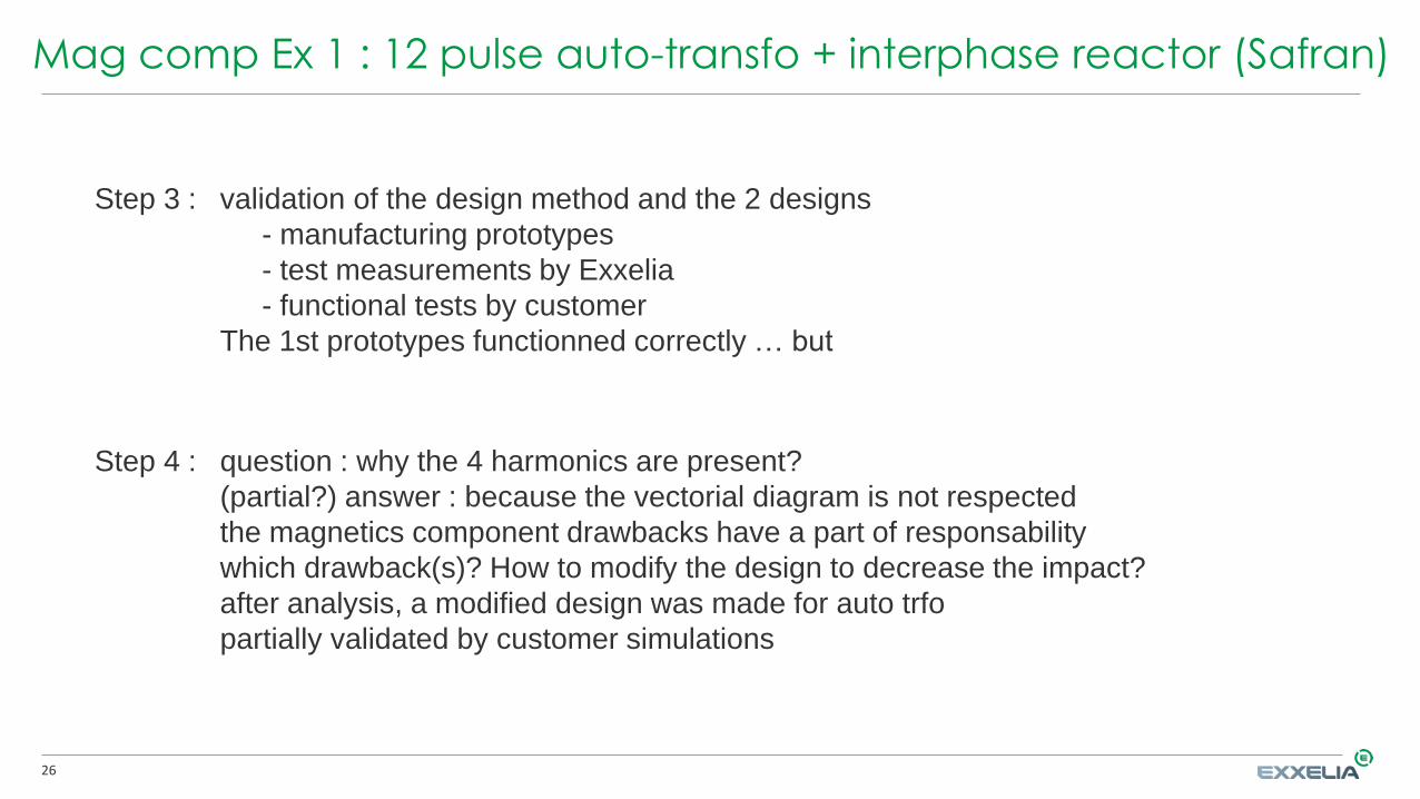
Step 3 : validation of the design method and the 2 designs
- manufacturing prototypes
- test measurements by Exxelia
- functional tests by customer
The 1st prototypes functionned correctly … but
Step 4 : question : why the 4 harmonics are present?
(partial?) answer : because the vectorial diagram is not respected
the magnetics component drawbacks have a part of responsability
which drawback(s)? How to modify the design to decrease the impact?
after analysis, a modified design was made for auto trfo
partially validated by customer simulations
27
Mag comp Ex 1 : 12 pulse auto-transfo + interphase reactor (Safran)
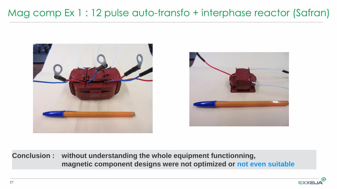
Conclusion : without understanding the whole equipment functionning,
magnetic component designs were not optimized or not even suitable
28
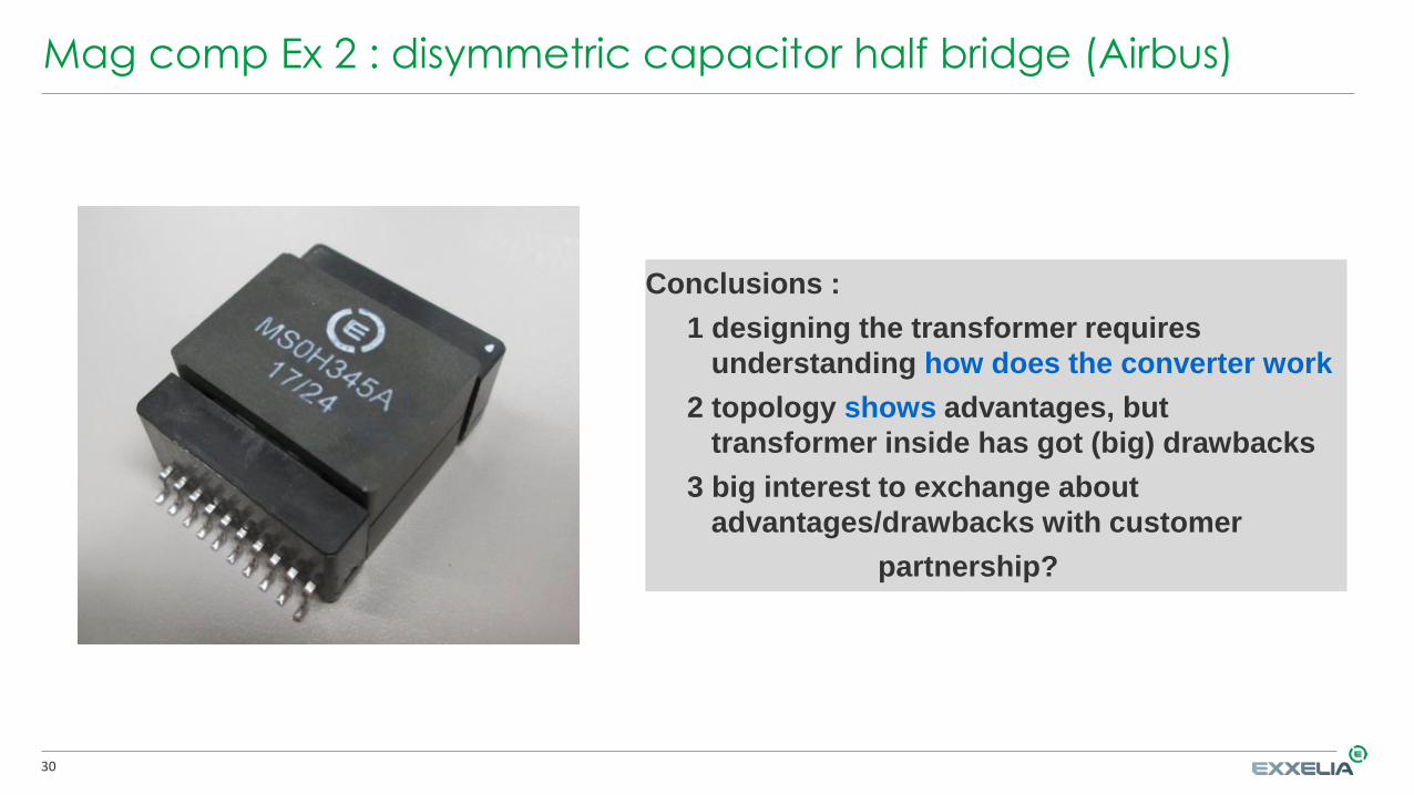
Mag comp Ex 2 : disymmetric capacitor half bridge (Airbus)
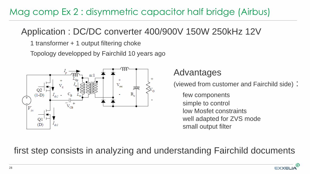
Application : DC/DC converter 400/900V 150W 250kHz 12V
1 transformer + 1 output filtering choke
Topology developped by Fairchild 10 years ago
Advantages
(viewed from customer and Fairchild side) :
few components
simple to control
low Mosfet constraints
well adapted for ZVS mode
small output filter
first step consists in analyzing and understanding Fairchild documents
29
Mag comp Ex 2 : disymmetric capacitor half bridge (Airbus)
Key point 1 : - viewed from primary side, transformer works as a continuous Flyback
- mean current component depends on Duty Cycle, so input voltage Ve
- reasoning is identical for induction
- continuous Bdc component can be greater than ripple ∆Bac
- the more important is Ve variation, bigger is the air-gap of the transformer
Key point 2 : - ZVS mode depends on leakage inductance value of transformer
- ZVS mode leads to a dead time for power transfer
- Dead time depends on Lk, Fs, D, Ve, N2/N1
- leak induc value must be neither too small nor too large and with small tolerance!
After understanding the converter operation and creating a design software module, it leads to the
conclusions below :
30
Mag comp Ex 2 : disymmetric capacitor half bridge (Airbus)
Conclusions :
1 designing the transformer requires
understanding how does the converter work
2 topology shows advantages, but
transformer inside has got (big) drawbacks
3 big interest to exchange about
advantages/drawbacks with customer
partnership?

31
Mag comp Ex 3 : 2 full bridges / 180° phase shift / 3 phases (Safran)
Application : 3 phases 45kVA 20/40kHz 400Hz inverter
mode 1 :
6 separated chokes
mode 2 :
3 coupled chokes
Why 3 coupled inductors?
some parameters offset each other
=> volume and/or weight reduction
Questions :- designing 1 (separated) choke OK
- designing 2 coupled chokes
How calculating accurately
leakage inductance?
- better thermal behaviour
with coupled chokes?

32
With : - formulae exist in university books (J.P. Ferrieux / F. Forest, D. Sadarnac, G. Seguier)
analytic - but with simplifying hypotheses : H field unidirectional
calculations - most of time, coupling is low and/or H field is really bidirectional
- insufficient to reach the desired accuracy
With : - most of time, need to use 3D simulations
finite - low coupling => formulation and meshing are tricky
element - low coupling + air-gap(s) => be careful to definition of infinite boundaries
simulations - leakage inductor + frequency + air-gap
(Flux) => magnetodynamics/harmonics with Eddy currents
- off set problem inherent in / related to finite element simulation
- extrapolation of results from one geometry to another difficult
Conclusion : designing a coupled choke is complex
requires a good level of knowledge of electromagnetism
thermal behaviour not better than simple inductor every time
How to calculate a leakage inductance with reasonable accuracy/tolerance?
Mag comp Ex 3 : 2 full bridges / 180° phase shift / 3 phases (Safran)

33
Mag comp : Other examples
Multicellular Parallel Converterscoupled chokes 2 by 2 or all around the same magnetic circuitworks with leakage inductances of coupled chokes
average power distribution depends on choke impedances
control/command/regulation complex and sensitive to coupled chokes drawbacks
Resonant converters :
I/V waveforms (harmonics) inside components very variable
strongest constraints can be at another frequency than that of resonance
=> at a lower power level than nom/max power
X Active Bridges family :
(1 of) advantages : multiple possibilities of control/command/regulation
example of aim : constant efficiency according to power or input voltage
drawback : (magnetic) component wave form analysis (very) complicated

34
Conclusion from Converter side view
• GaN and SiC technologies allow to increase (a lot) switching frequenciesand/or reduce inverter/rectifier cell losses
• New topologies create new interactions betweeninverter/rectifier cells and magnetic component(s)
• New digital technologies allow to do multi variable control/command/regulation
• Main losses and challenges are now on magnetic components : undertanding interactions between component and its environmentmagnetic drawback control
• Safran ① is aware of importance of magnetics to succeed in increasingconverter switching frequencies and so ② wants to acquire a betterknowledge of magnetics behavior and design

35
Conclusion from Magnetic Component side view
The era of design with some simple rules of electromagnetism is :
over
Design compliant with future needs in aeronautics results from
a system approach
understanding magnetic component environment
taking into account multi-domain physical phenomena
need to communicate and interact with customers
=> relationship between supplier (sub contractor) / customer becomes partnership
It is neither more nor less than a cultural revolution
it has already started for several years – our customers are ahead of us
will we able to take up this challenge in time?

Thank you for your attention
Questions?
Bruno COGITORESenior R&D Engineer • Exxelia Magnetics
Phone: +33 (0)4 76 35 05 92
Cell: +33 (0)6 99 36 16 47
Louis GRIMAUD – Bertrand LACOMBEResponsable R&T – Expert Conversion • Safran