Embed Size (px)
Citation preview
National Aeronautics and Space Administration Aeronautics Research Mission Directorate
Aviation Safety Program
Integrated Resilient Aircraft Control
“Stability, Maneuverability, and Safe Landing in the Presence of Adverse Conditions”
Principal Investigator: Kalmanje Krishnakumar Project Manager: Sally Viken
Project Scientist: Nhan Nguyen
May 1, 2009
1
1.1 Project Scope .................................................................................................................. 7 1.2 Relevance........................................................................................................................ 7
1.2.1 Current State-of-the-Art.............................................................................................. 8 1.2.2 Benefits of the Research ........................................................................................... 10
1.3 Milestones and Metrics ................................................................................................. 11 1.4 Technical Approach ...................................................................................................... 13
IRAC 4.1 Multidisciplinary Integrated Aircraft Control Design Tools and Techniques ..... 15 IRAC 4.2 Systems Analysis for Robust Configurations....................................................... 20 IRAC 3.1 Integrated Adaptive Aircraft Control for Stability and Safe Maneuverability..... 21 IRAC 3.2 Integrated Adaptive Mission Management Tools for Safe Flight........................ 23 IRAC 3.3 Validation Methods for Adaptive Systems .......................................................... 25 IRAC 2.0 Level 2 Disciplinary Research ............................................................................. 27 IRAC 2.1 Integrated Dynamics and Flight Control .............................................................. 27
IRAC 2.1.1 Adaptive Control Methods under Adverse Events........................................ 27 IRAC 2.1.2 Aircraft Modeling Methods for Flight Control Development....................... 30
IRAC 2.2 Integrated Propulsion Control and Dynamics ...................................................... 33 IRAC 2.3 Airframe and Structural Dynamics....................................................................... 35 IRAC 2.4 Intelligent Flight Planning and Guidance............................................................. 37 IRAC 2.5 Verification and Validation Methods and Testbeds ............................................. 39 Foundational Research.......................................................................................................... 44 IRAC 1.1 Control Theory and Methods ............................................................................... 45 IRAC 1.2 Modeling Methods ............................................................................................... 50 IRAC 1.3 V&V Methods ...................................................................................................... 59 Leveraged Research: Condition/Capability Assessment ...................................................... 62
2
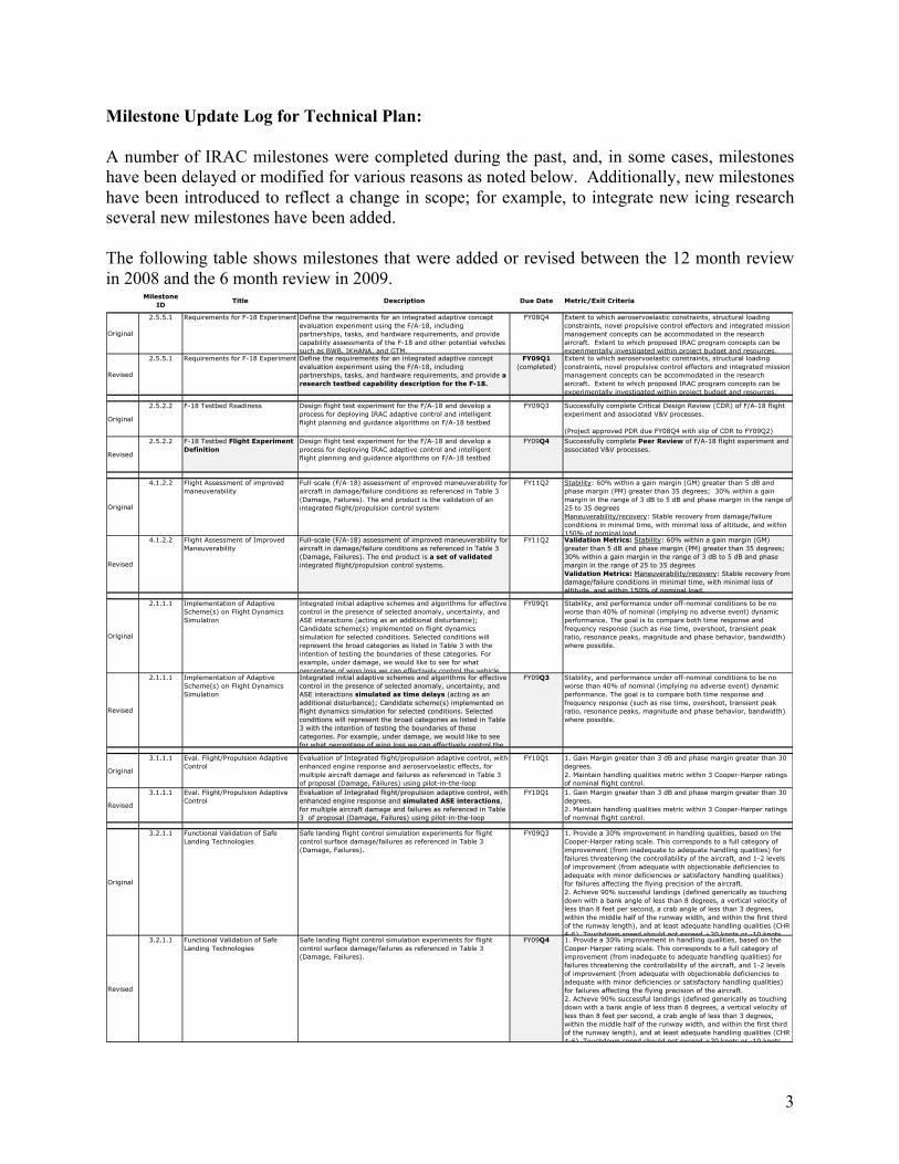
Milestone Update Log for Technical Plan: A number of IRAC milestones were completed during the past, and, in some cases, milestones have been delayed or modified for various reasons as noted below. Additionally, new milestones have been introduced to reflect a change in scope; for example, to integrate new icing research several new milestones have been added. The following table shows milestones that were added or revised between the 12 month review in 2008 and the 6 month review in 2009.
3
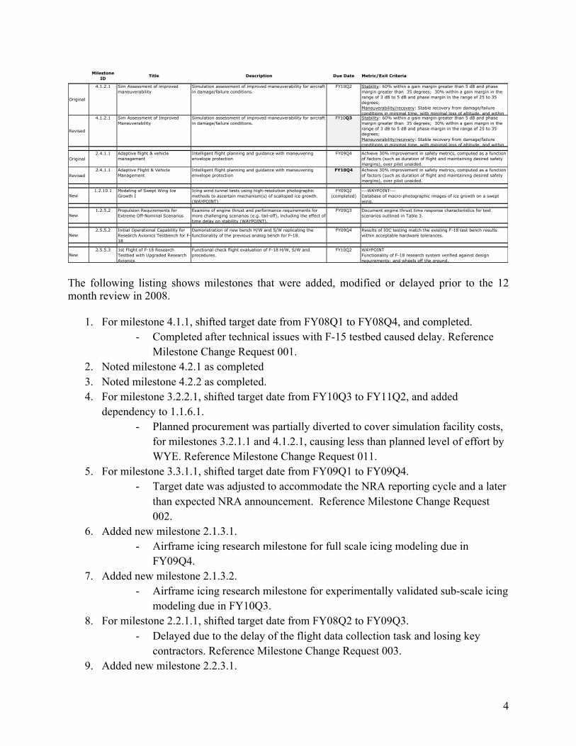
The following listing shows milestones that were added, modified or delayed prior to the 12 month review in 2008.
1. For milestone 4.1.1, shifted target date from FY08Q1 to FY08Q4, and completed. - Completed after technical issues with F-15 testbed caused delay. Reference
Milestone Change Request 001. 2. Noted milestone 4.2.1 as completed 3. Noted milestone 4.2.2 as completed. 4. For milestone 3.2.2.1, shifted target date from FY10Q3 to FY11Q2, and added
dependency to 1.1.6.1. - Planned procurement was partially diverted to cover simulation facility costs,
for milestones 3.2.1.1 and 4.1.2.1, causing less than planned level of effort by WYE. Reference Milestone Change Request 011.
5. For milestone 3.3.1.1, shifted target date from FY09Q1 to FY09Q4. - Target date was adjusted to accommodate the NRA reporting cycle and a later
than expected NRA announcement. Reference Milestone Change Request 002.
6. Added new milestone 2.1.3.1. - Airframe icing research milestone for full scale icing modeling due in
FY09Q4. 7. Added new milestone 2.1.3.2.
- Airframe icing research milestone for experimentally validated sub-scale icing modeling due in FY10Q3.
8. For milestone 2.2.1.1, shifted target date from FY08Q2 to FY09Q3. - Delayed due to the delay of the flight data collection task and losing key
contractors. Reference Milestone Change Request 003. 9. Added new milestone 2.2.3.1.
4
- Engine icing research milestone for iced compression system performance due in FY10Q3.
10. For milestone 2.5.1.1, shifted target date from FY08Q3 to FY09Q3. - A re-prioritization for earlier than planned closed-loop experimentation
caused this milestone to be delayed and motivated the introduction of milestone 2.5.1.2. Reference Milestone Change Requests 004 and 013.
11. Added new milestone 2.5.1.2. - Sub-scale flight testbeds milestone for closed loop experimentation capability
due in FY09Q1. 12. For milestone 2.5.2.2, shifted target date from FY08Q4 to FY09Q3.
- Programmatic and resource uncertainties caused this milestone to be delayed. Reference Milestone Change Request 005.
13. For milestone 2.5.5.1, shifted target date from FY08Q3 to FY08Q4. - Programmatic and resource uncertainties caused this milestone to be delayed.
Reference Milestone Change Request 006. 14. Noted milestone 1.1.1.1 as completed. 15. For milestone 1.1.3.1, shifted target date from FY08Q3 to FY08Q4, and completed.
- Completed after workforce issues caused small delay. Reference Milestone Change Request 009.
16. Added new milestone 1.1.6.1. - Foundational control theory milestone for conformant and contingency
planning for flight envelope uncertainty due in FY10Q1. 17. For milestone 1.2.3.1, modified Metrics, and completed.
- Scope of original milestone was too broad for amount of supporting work activity. This milestone, now completed, addresses the development rigid-body simulation and a new milestone 1.2.3.3 has been introduced for the flight validation of this simulation. Reference Milestone Change Request 012.
18. Noted milestone 1.2.4.1 as completed. 19. Added new milestone 1.2.3.3.
- Integrated aircraft response modeling milestone for the validation of a 6-DOF full envelope aircraft simulation due in FY09Q3.
20. For milestone 1.2.5.1, shifted target date from FY08Q3 to FY08Q4, and completed. - Completed after workforce issues caused small delay. Reference Milestone
Change Request 008. 21. Added new milestone 1.2.10.1.
- Airframe icing research milestone for modeling of swept wing ice growth due in FY10Q3.
22. Added new milestone 1.2.11.1. - Engine icing research milestone for engine ice-particle dynamics and
thermodynamics due in FY09Q3.
5

23. Noted milestone 1.3.2.1 as completed.
6
1. Technical Plan
1.1 Project Scope
The Integrated Resilient Aircraft Control (IRAC) Project will conduct research to advance the state of aircraft flight control to provide onboard control resilience for ensuring safe flight in the presence of adverse conditions. The goal of the IRAC project is to arrive at a set of validated multidisciplinary integrated aircraft control design tools and techniques for enabling safe flight in the presence of adverse conditions (ex: faults, damage and/or upsets). One objective towards this goal is to advance the state-of-the-art of adaptive controls as a design option to provide enhanced stability and maneuverability margins for safe landing. Adverse events include loss of control caused by environmental factors, actuator and sensor faults or failures, and will expand toward more complicated damage conditions. The application focus of this technology is for current and next generation subsonic civil transports. However, a majority of the challenges addressed by the IRAC project are general in nature, and therefore, the solutions will apply to a large class of aviation vehicles. Integrated adaptive controls require improved models that include system interactions between structures, flight controls and/or the propulsion system. These modeling efforts will strive to achieve dynamically representative interactions to allow for control law design and evaluation. An example is the need for improved departure and post-departure dynamic modeling of a civil transport class aircraft. Details of the dynamics involved in loss of control are required to better understand how the adaptive system can best regain control without further exacerbating the situation. Another example includes the enhancements to propulsion modeling for situations requiring effective integrated flight and propulsion control. Successful transition of foundational research into national airspace system deployment relies greatly on the ability to verify and validate integrated adaptive control technologies. Efforts for validation will utilize simulators, wind tunnels, and sub- and full-scale flight test vehicles. Research and technologies from other Aeronautics projects across NASA will be leveraged where found to be beneficial to the IRAC project.
1.2 Relevance
Given the projected increase in air traffic in the National Airspace System, IRAC is considered highly relevant to reducing the fatal accident rate in the classifications known as “loss-of-control” and “system/component failure or malfunction”. When combined, these classifications account for the largest number of fatalities between 1987 and 2005 (Appendix A, Sections A.1 and A.2). The IRAC goal and objective are aligned with the Aviation Safety Program Goals, and the Agency Roles and Responsibilities as articulated in the National Aeronautics Research and Development Policy (released on 20 December 2006), and summarized below:
The National Aeronautics Research and Development Policy issued on 20 December 2006 specified that the United States should be guided by several principles required to maintain technological leadership across the aeronautics enterprise. One of the principles is “Aviation safety is paramount”.
“Every individual who enters an airport or boards an aircraft expects to be safe. To that end, continual improvement of safety of flight must remain at the forefront of the U.S. aeronautics agenda.”
7
Section V of the policy specifies roles and responsibilities of the Executive Departments and Agencies. NASA’s roles and responsibilities are:
“The National Aeronautics and Space Administration (NASA) should maintain a broad foundational research effort aimed at preserving the intellectual stewardship and mastery of aeronautics core competencies so that the nation's world-class aeronautics expertise is retained. These core competencies also include key aeronautical capabilities that support NASA's human and robotic space activities.”
Joint Planning and Development Office (JPDO) integrated work plan (Version 0.2) for the Next Generation Air Transportation System (NextGen) released on Feb 15, 2008 has identified several areas that will require the critical research, including adaptive controls and automation-assisted flight planning. These needs are partially driven by the needs of safety as identified by the work plan (Lines 2780-2784).
“Improving safety is an integral and enabling component of the air transportation system’s transformation, since even a perceived lack of safety would negatively impact demand. The JPDO is charged with improving safety through the introduction of safety-enhancing technologies and developing a proactive approach, while the system accommodates a significant increase (up to three times) in the current level of air traffic operations”.
The Aviation Safety Program Goals as defined in the NASA FY08 Budget Request are: Develop technologies, tools, and methods to:
- Improve aircraft safety for current and future aircraft - Overcome safety technology barriers that would otherwise constrain full realization of the Next Generation Air Transportation System - Concurrently, these technologies can be leveraged to support space exploration activities, such as enabling self-reliant and intelligent systems necessary for the long-duration travel requirements of future space vehicles.
1.2.1 Current State-of-the-Art
The IRAC Project recognizes several internal and external sources that cite the current state-of-the-art, the future challenges, and the value-added benefits of the proposed research. These sources have all been considered and embraced in formulating the technical approach and roadmap discussed in the ensuing subsections. Examples of these sources include:
2004: NASA Adaptive Controls Task Force 2004: National Research Council Review of NASA’s Aerospace Technology Enterprise
Panel for Computing, Information, and Communication Technology Panel for Vehicle Systems Panel for Aviation Safety
2006: Decadal Survey for Civil Aeronautics Panel D: Dynamics, Navigation, Control, and Avionics
8
In 2004 a NASA Aeronautics “Adaptive Controls Task Force” with representation from NASA Ames, Dryden, Glenn, and Langley observed that existing flight control technology is not adequate to handle large uncertainties and system changes, unknown component failures and anomalies, high degree of complexity, non-linear unsteady dynamics, revolutionary vehicles, and novel actuators and sensors. The Task Force further observed that uncertainties and system changes can be continuous or discrete, such as varying flight conditions, abrupt failures, and structural damage, to name a few.
The results of the NASA Task Force were presented to Panel D (Dynamics, Navigation, Control, and Avionics) of the Decadal Survey for Civil Aeronautics, which released its findings in 2006. The panel included representation from Academia, Industry, and Other Government Agencies. The top challenges cited by Panel D corroborated the NASA Task Force observations, and prioritized the flight control research and technology challenges that have high relevance to aviation safety. The Panel D challenges applicable to IRAC are as follows:
D.1 Advanced guidance systems D.2 Decision-making under uncertainty, and flight path planning and prediction D.4 Intelligent and adaptive flight control techniques D.14 Design, development, and upgrade processes for complex, software-intensive systems, including tools for design, development, and validation and verification.
In 2004, the National Research Council released its review of NASA’s Aerospace Technology Enterprise. The panel on Computing, Information and Communication Technology (CICT) highlighted 17 out of 242 tasks that are examples of world-class work. One of the 17 tasks was “Intelligent Flight Control” (IFC), which has been incorporated into the IRAC Project. The panel for Vehicle Systems (specifically the portion of the Revolutionary Aircraft Flight Validation Subproject that supported IFC flight validation) was also commended, and incorporated into the IRAC Project, as well:
“Future applications will almost certainly be much wider and will one day be integrated into civilian transport because this technology has great promise for flight controls transparency in the presence of system component failures”
“This is a clear-cut example of what NASA is uniquely qualified to do in a step-by-step process that ends in flight test. The committee commends NASA for its innovation in acquiring assets to conduct the testing. The combination of these entities under the NASA rubric is world-class”
Finally, the panel for Aviation Safety (Single Aircraft Accident Prevention Subproject) cited: “The committee believes the work involved in scale-model testing serves to integrate the diverse components involved in the CUPR [Control Upset Prevention and Recovery] tasks, and NASA should increase its efforts in such integration activities”
In summary, the aviation community has supported research in the area of integrated resilient aircraft control, both from the safety viewpoint and also from the complexity viewpoint. The results of the investment in IRAC must also be realized in a timely fashion to improve the design of aircraft currently on the drawing board and those envisioned in the future to overcome the safety technology barriers that would otherwise constrain the full realization of NextGen.
9
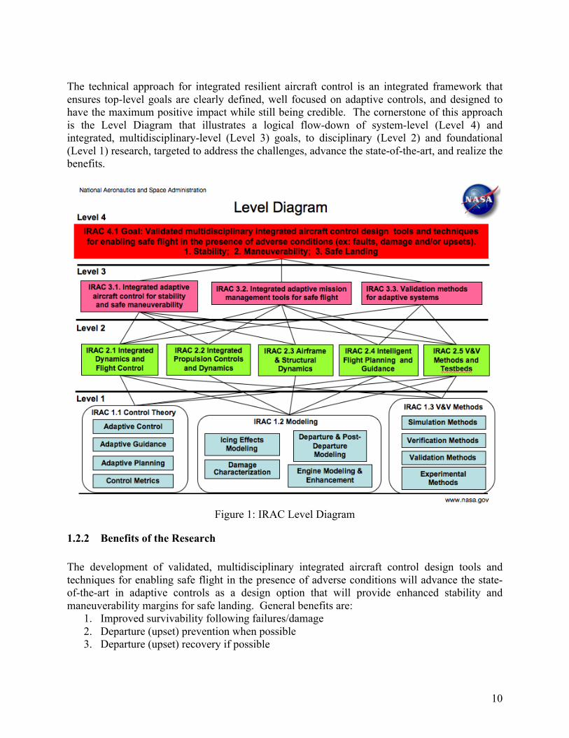
The technical approach for integrated resilient aircraft control is an integrated framework that ensures top-level goals are clearly defined, well focused on adaptive controls, and designed to have the maximum positive impact while still being credible. The cornerstone of this approach is the Level Diagram that illustrates a logical flow-down of system-level (Level 4) and integrated, multidisciplinary-level (Level 3) goals, to disciplinary (Level 2) and foundational (Level 1) research, targeted to address the challenges, advance the state-of-the-art, and realize the benefits.
Figure 1: IRAC Level Diagram
1.2.2 Benefits of the Research
The development of validated, multidisciplinary integrated aircraft control design tools and techniques for enabling safe flight in the presence of adverse conditions will advance the state-of-the-art in adaptive controls as a design option that will provide enhanced stability and maneuverability margins for safe landing. General benefits are:
1. Improved survivability following failures/damage 2. Departure (upset) prevention when possible 3. Departure (upset) recovery if possible
10
Specific benefits of this research include: (i) improved understanding, characterization, and prediction of coupled effects associated with adverse conditions that threaten aircraft flight safety; (ii) increased aircraft survivability and control resilience under adverse conditions; (iii) improved vehicle performance and handling qualities under adverse conditions; and (iv) the safety assurance of adaptive safety-critical technologies for utilization in the National Airspace System (NAS) and NextGen. These payoffs will have a direct impact on adverse conditions associated with vehicle impairment due to damage, failures, and upsets:
1. For subsonic civil transport aircraft, which have built-in control redundancy, adaptive control will provide stable flight in the midst of an adverse event. In addition to providing stability, intelligent flight planning and guidance will enable the pilot to maneuver the aircraft to safe landing within constraints dictated by the adverse event.
2. For next generation aircraft, such as blended wing designs and tail-less configurations, in addition to safe response to adverse events, adaptive control will be an enabler for optimum performance throughout the flight envelop. Also, adaptive control along with intelligent planning and guidance will provide an excellent way to test designs without the excessive avionics cost associated with new control-law developments.
Although quantitative projections of the benefits of IRAC research on the future fatal accident rate are the subject of systems analysis studies that are planned as part of this project (and discussed in detail in Section 1.4, Systems Analysis for Robust Configurations, IRAC 4.2), existing data provides an indication of potential benefits. In particular, eight transport accidents occurred from 1977-2005, resulting in 1114 fatalities. (Appendix A, Section A.3). In support of aviation safety, the National Institute of Aerospace report cited damage adaptive control and recovery as providing potentially life-saving technology. The USAF Large Aircraft Survivability Initiative (LASI), the Department of Homeland Security (DHS), and the U.S. Naval Air Systems Command (NAVAIR) all have a high interest and need for technologies that enable damage modeling, safety-of-flight and recoverability assessment, and damage mitigation for transport aircraft. (Appendix E, Partnership Plan). While these interests center on safety risks resulting from security threats (e.g., shoulder-launched missiles), the development of methods and tools for generic damage scenarios is highly relevant and of vital importance.
1.3 Milestones and Metrics
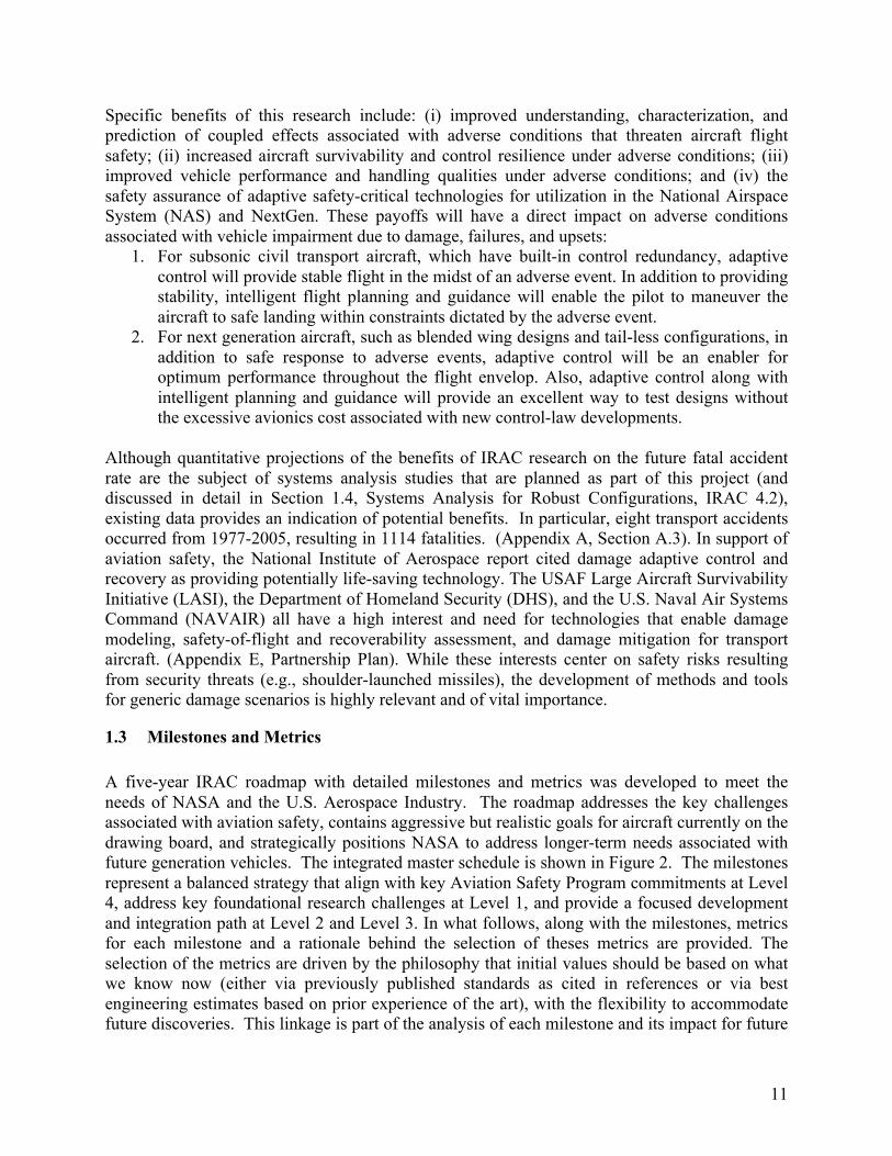
A five-year IRAC roadmap with detailed milestones and metrics was developed to meet the needs of NASA and the U.S. Aerospace Industry. The roadmap addresses the key challenges associated with aviation safety, contains aggressive but realistic goals for aircraft currently on the drawing board, and strategically positions NASA to address longer-term needs associated with future generation vehicles. The integrated master schedule is shown in Figure 2. The milestones represent a balanced strategy that align with key Aviation Safety Program commitments at Level 4, address key foundational research challenges at Level 1, and provide a focused development and integration path at Level 2 and Level 3. In what follows, along with the milestones, metrics for each milestone and a rationale behind the selection of theses metrics are provided. The selection of the metrics are driven by the philosophy that initial values should be based on what we know now (either via previously published standards as cited in references or via best engineering estimates based on prior experience of the art), with the flexibility to accommodate future discoveries. This linkage is part of the analysis of each milestone and its impact for future
11
milestones. In some instances, the metrics are part of foundational research that will be carried out in the beginning of the project. As an example, Milestone 1.1.1.1 addresses metrics for adaptive control performance. This milestone will help us refine some of the initial estimates made on accuracies needed for modeling (see Milestones 2.1.2.1, 2.1.2.2, 2.3.1.1, and 2.3.1.2) to ensure stable adaptive controller performance. The IRAC Project also recognizes the need for systems analysis to gain insight into future requirements derived from probable adverse conditions and trends that might influence the research portfolio and assessment/validation aspects of the project. This activity is captured at Level 4, and any new future requirements resulting from systems analysis will be examined relative to the benefit to Aviation Safety.
Figure 2. IRAC 5-Year Roadmap
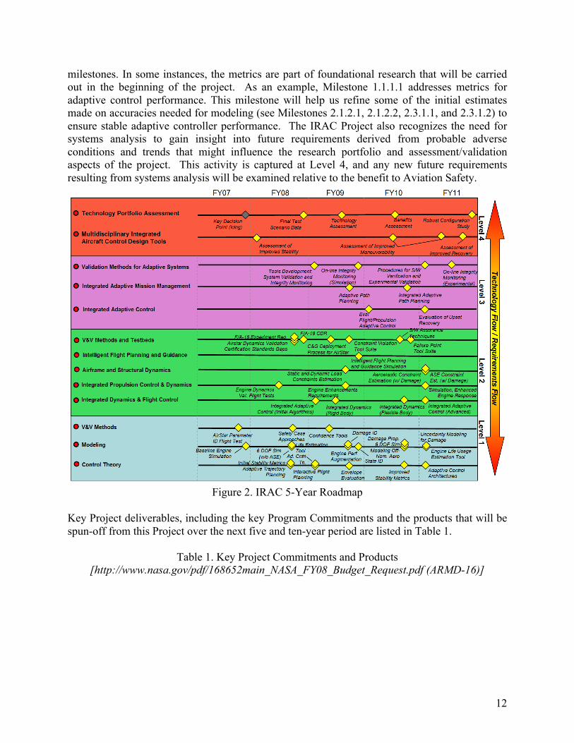
Key Project deliverables, including the key Program Commitments and the products that will be spun-off from this Project over the next five and ten-year period are listed in Table 1.
Table 1. Key Project Commitments and Products [http://www.nasa.gov/pdf/168652main_NASA_FY08_Budget_Request.pdf (ARMD-16)]
12
1.4 Technical Approach The goal of the IRAC project is to arrive at a set of validated multidisciplinary integrated aircraft control design tools and techniques for enabling safe flight in the presence of adverse conditions (ex: faults, damage and/or upsets). This proposal describes the technical challenges, an integrated approach to addressing these challenges, and what will be accomplished over the first five years of this Project within the resources provided. This is summarized in Table 2 and discussed in detail in the subsections that follow, and particularly the foundational research approach is expanded on in subsections IRAC 1.1, 1.2, and 1.3.
Table 2. Challenges, Integrated Technical Approach, and 5-Year Accomplishments
13
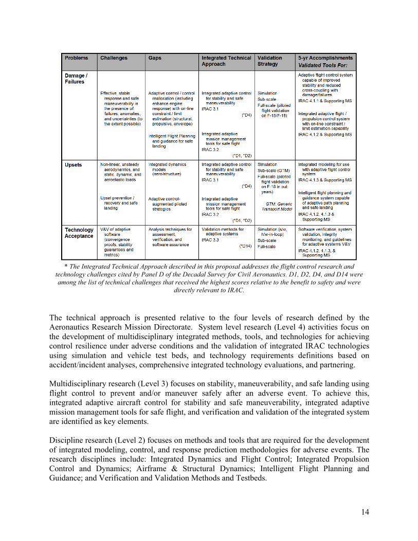
* The Integrated Technical Approach described in this proposal addresses the flight control research and technology challenges cited by Panel D of the Decadal Survey for Civil Aeronautics. D1, D2, D4, and D14 were among the list of technical challenges that received the highest scores relative to the benefit to safety and were
directly relevant to IRAC.
The technical approach is presented relative to the four levels of research defined by the Aeronautics Research Mission Directorate. System level research (Level 4) activities focus on the development of multidisciplinary integrated methods, tools, and technologies for achieving control resilience under adverse conditions and the validation of integrated IRAC technologies using simulation and vehicle test beds, and technology requirements definitions based on accident/incident analyses, comprehensive integrated technology evaluations, and partnering.
Multidisciplinary research (Level 3) focuses on stability, maneuverability, and safe landing using flight control to prevent and/or maneuver safely after an adverse event. To achieve this, integrated adaptive aircraft control for stability and safe maneuverability, integrated adaptive mission management tools for safe flight, and verification and validation of the integrated system are identified as key elements.
Discipline research (Level 2) focuses on methods and tools that are required for the development of integrated modeling, control, and response prediction methodologies for adverse events. The research disciplines include: Integrated Dynamics and Flight Control; Integrated Propulsion Control and Dynamics; Airframe & Structural Dynamics; Intelligent Flight Planning and Guidance; and Verification and Validation Methods and Testbeds.
14
Foundational research (Level 1) focuses on fundamental theory and methods for the characterization of adverse conditions, theoretical advances in adaptive control, intelligent planning and guidance, and relevant control metrics for measuring available stability and controllability margins. Fundamental theory and methods will be developed in physics-based computational modeling of fluid, structural, and engine dynamics to characterize the effects of adverse conditions, control under adverse conditions, experimental methods for testing under these conditions, and the validation and verification of adaptive and learning systems.
IRAC 4.1 Multidisciplinary Integrated Aircraft Control Design Tools and Techniques Problem Statement: The focus of the IRAC project is in addressing adaptive flight control technologies that will revolutionize current approaches available to accommodate adverse conditions. The project objectives are to advance the state-of-the-art in adaptive controls as a design option that will provide enhanced stability and maneuverability margins for safe landing in adverse conditions. As stated earlier, there are many foundational challenges associated with resilient aircraft control. At the highest level, the challenges are in arriving at provable adaptive control approaches that can be tested in realistic environments. In addition, by design, adaptive flight control system software is self-modifying and thus does not fit the traditional processes of validation of the aircraft closed-loop stability and robustness characteristics which are currently mandatory to achieve flight certification.
Previous Related Research: Control upset prevention and recovery (CUPR) and damage adaptive control systems (DACS) research was initiated under the NASA Aviation Safety and Security Program (AvSSP). The CUPR effort focused on aerodynamics modeling of vehicle upset conditions, on systems technologies for failure detection, identification, and accommodation through control reconfiguration, and on some preliminary methods for upset recovery. The DACS research initiated the development of a multidisciplinary damage modeling approach to characterizing the coupled multidisciplinary effects of vehicle damage. Research into intelligent flight control systems (IFCS) was initiated under NASA’s Vehicle Systems Program (VSP). This research focused on the development of direct adaptive control methods for failure accommodation using neural networks. The development of an integrated V&V process (including analytical, simulation-based, and experimental methods) for safety-critical control systems was initiated under the AvSSP CUPR activity, as well as the Strategic Methods for Autonomous and Robust Technology Testing (SMART-T) activity under the NASA Vehicle Systems Program (VSP) Flight & Systems Demonstration (F&SD) Project.
Research Approach: The approach is based on fundamental questions that will be posed by any flight control engineer and pilot alike. How do I guarantee stability for a range of adverse events? How do I maneuver out of an upset condition? How do I safely land the impaired vehicle? Several approaches will be developed to precisely answer the questions raised above. These approaches can be broadly classified as integrated and adaptive flight and propulsion control for improved stability and maneuverability; pilot-augmented adaptive control strategies for upset recovery; and intelligent flight planning and guidance for safe landing. The milestones described in this section span the stability, maneuverability, and safe-landing objectives of IRAC.
15
Simulation and/or flight validation of controller performance during an adverse event poses several challenges. Current state-of-the-art in aircraft modeling cannot accurately predict aerodynamic and/or flight dynamic characteristics under departed and loss-of-control conditions. Consideration of airframe failure and damage conditions further complicate this task. Improvements in the models for these conditions are sought; however, in parallel with this are efforts to improve the ability of control algorithms to deal with model uncertainty and to accommodate changes in the system. The focus on an off-nominal flight regime also increases the need for experimental validation. The research approach therefore invests in flight assets, both remotely piloted subscale vehicles and manned full-scale aircraft that will allow for high-risk experiments to increase fundamental understanding, and measure progress on adaptive flight controls.
Technology Validation Strategy: The technology validation strategy at Level 4 and Level 3 is multi-faceted. It includes flight simulation, subscale testing, and full-scale validation so the multidisciplinary tools produced by IRAC can be validated with the requisite level of confidence. The adverse conditions selected for test and validation will be driven by several factors:
1. The ability to use data-mining tools in predicting probable adverse conditions of significance
2. The ability to model and control adverse events for simulation-based evaluation 3. The ability to flight test representative adverse events.
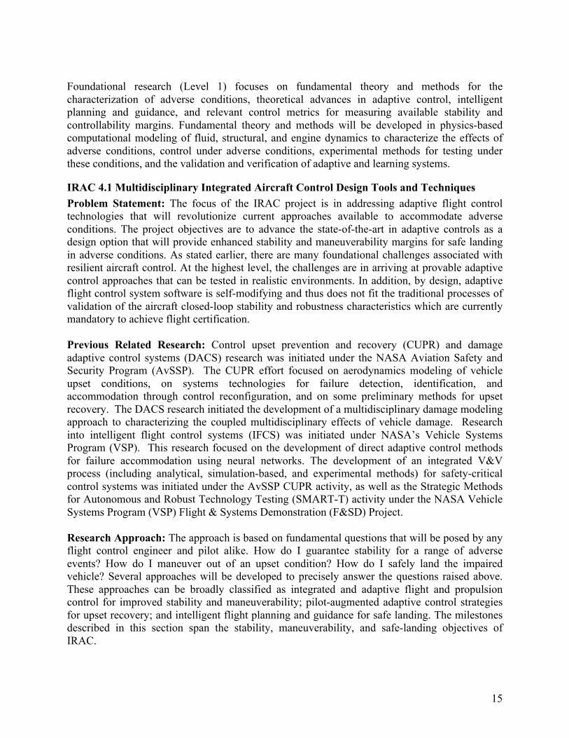
An initial set of adverse conditions is presented in Table 3. This set is driven by the philosophy that milestones and metrics are based on what we know now, with flexibility to accommodate future discoveries planned as part of Systems Analysis for Robust Configurations (which leverages data-mining research in IVHM, see IRAC 4.2). The strategy includes a methodical approach to establish requirements and test criteria for major experiments at Level 2, and evaluations of adverse conditions in simulation at Level 3 prior to flight validation at Level 4.
Table 3. Initial Set of Adverse Conditions. Adverse Conditions
Initial Test Conditions Milestone References
Failures Static and dynamic actuator failure effects (single actuator and multiple actuator failures) Examples: • Locked stabilator, (F-15) • Stabilator driven to local
angle-of-attack (F/A-18) • Reduced control surface
effectiveness due to icing.
Baseline F-15 adaptive control assessment/validation IRAC 4.1.1
Systems analysis/data mining for test condition refinement IRAC 4.2.2 (leverages IVHM data-mining expertise)
Requirements and test criteria IRAC 2.5.2.2
Simulation evaluation of test conditions IRAC 3.1.1.1, 3.2.1.1, and 4.1.2.1
Full-Scale F/A-18 assessment/validation IRAC 4.1.2.2
Damage Aerodynamic & structural damage (Wing and/or Tail) Examples: • Destabilizing angle-of-attack
feedback to the canards, wing damage simulation (F-15)
• Locked flaps (F/A-18) • Aerodynamic uncertainty
caused by icing
Baseline F-15 adaptive control assessment/validation IRAC 4.1.1
Systems analysis/data mining for test condition refinement IRAC 4.2.2 (leverages IVHM data-mining expertise)
Requirements and test criteria IRAC 2.5.2.2
Simulation evaluation of test conditions IRAC 3.1.1.1, 3.2.1.1, and 4.1.2.1
Full-Scale F/A-18 assessment/validation
16
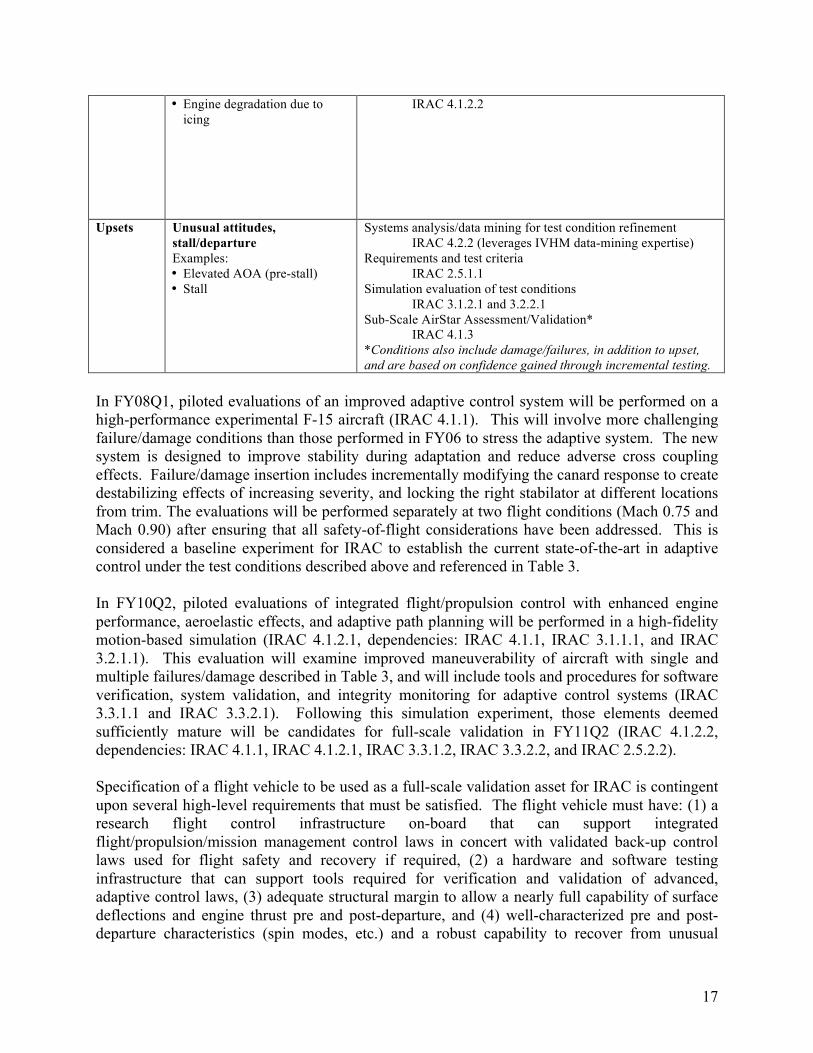
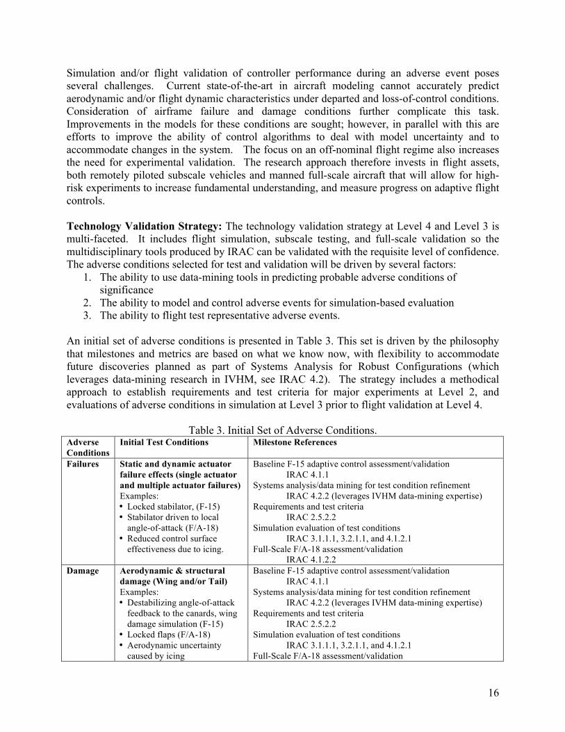
• Engine degradation due to icing
IRAC 4.1.2.2
Upsets Unusual attitudes, stall/departure Examples: • Elevated AOA (pre-stall) • Stall
Systems analysis/data mining for test condition refinement IRAC 4.2.2 (leverages IVHM data-mining expertise)
Requirements and test criteria IRAC 2.5.1.1
Simulation evaluation of test conditions IRAC 3.1.2.1 and 3.2.2.1
Sub-Scale AirStar Assessment/Validation* IRAC 4.1.3
*Conditions also include damage/failures, in addition to upset, and are based on confidence gained through incremental testing.
In FY08Q1, piloted evaluations of an improved adaptive control system will be performed on a high-performance experimental F-15 aircraft (IRAC 4.1.1). This will involve more challenging failure/damage conditions than those performed in FY06 to stress the adaptive system. The new system is designed to improve stability during adaptation and reduce adverse cross coupling effects. Failure/damage insertion includes incrementally modifying the canard response to create destabilizing effects of increasing severity, and locking the right stabilator at different locations from trim. The evaluations will be performed separately at two flight conditions (Mach 0.75 and Mach 0.90) after ensuring that all safety-of-flight considerations have been addressed. This is considered a baseline experiment for IRAC to establish the current state-of-the-art in adaptive control under the test conditions described above and referenced in Table 3.
In FY10Q2, piloted evaluations of integrated flight/propulsion control with enhanced engine performance, aeroelastic effects, and adaptive path planning will be performed in a high-fidelity motion-based simulation (IRAC 4.1.2.1, dependencies: IRAC 4.1.1, IRAC 3.1.1.1, and IRAC 3.2.1.1). This evaluation will examine improved maneuverability of aircraft with single and multiple failures/damage described in Table 3, and will include tools and procedures for software verification, system validation, and integrity monitoring for adaptive control systems (IRAC 3.3.1.1 and IRAC 3.3.2.1). Following this simulation experiment, those elements deemed sufficiently mature will be candidates for full-scale validation in FY11Q2 (IRAC 4.1.2.2, dependencies: IRAC 4.1.1, IRAC 4.1.2.1, IRAC 3.3.1.2, IRAC 3.3.2.2, and IRAC 2.5.2.2).
Specification of a flight vehicle to be used as a full-scale validation asset for IRAC is contingent upon several high-level requirements that must be satisfied. The flight vehicle must have: (1) a research flight control infrastructure on-board that can support integrated flight/propulsion/mission management control laws in concert with validated back-up control laws used for flight safety and recovery if required, (2) a hardware and software testing infrastructure that can support tools required for verification and validation of advanced, adaptive control laws, (3) adequate structural margin to allow a nearly full capability of surface deflections and engine thrust pre and post-departure, and (4) well-characterized pre and post-departure characteristics (spin modes, etc.) and a robust capability to recover from unusual
17
attitudes and departure. Candidate platforms would include, F-15 used in the Intelligent Flight Control System project (tail number 837), and an F/A-18 modified with a research flight control processor (tail number 853). Of these platforms, the F/A-18 has the greatest capability, flexibility, and sustainability.
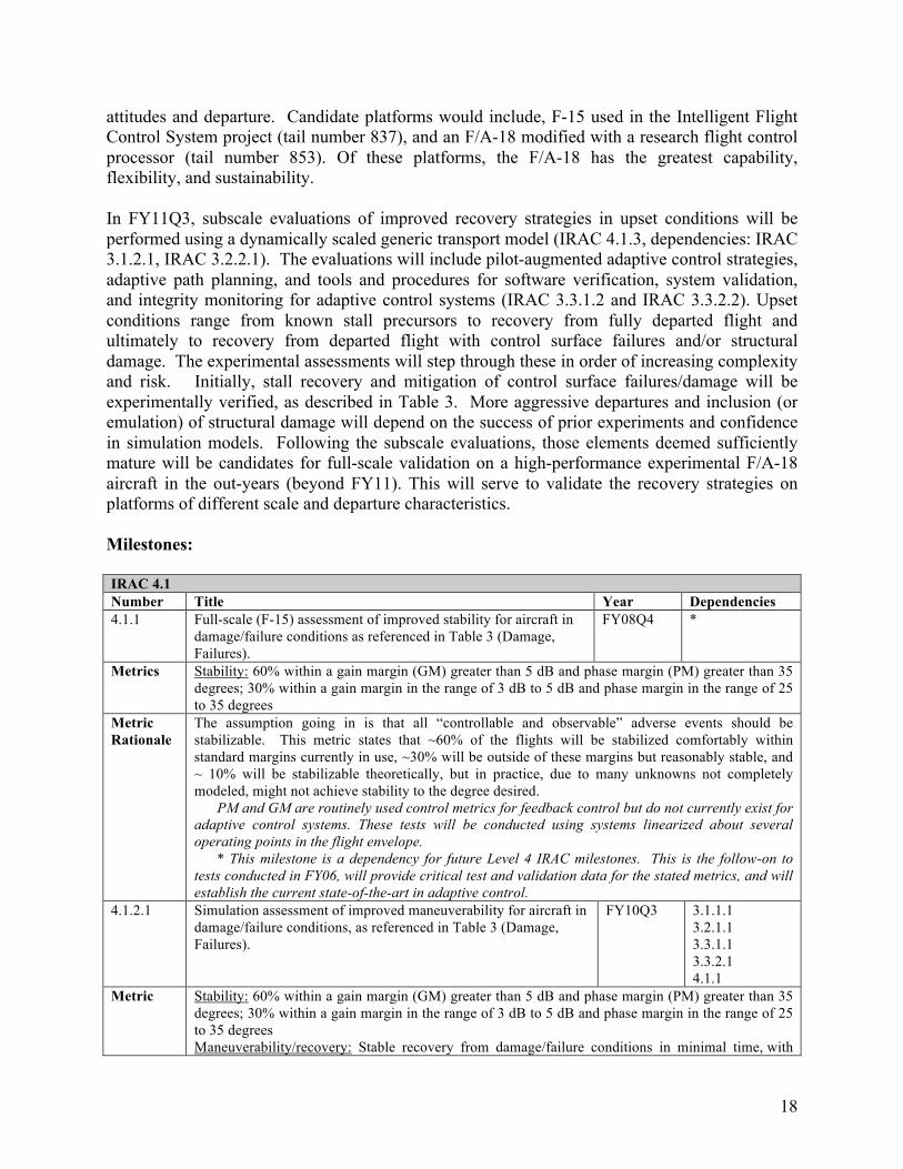
In FY11Q3, subscale evaluations of improved recovery strategies in upset conditions will be performed using a dynamically scaled generic transport model (IRAC 4.1.3, dependencies: IRAC 3.1.2.1, IRAC 3.2.2.1). The evaluations will include pilot-augmented adaptive control strategies, adaptive path planning, and tools and procedures for software verification, system validation, and integrity monitoring for adaptive control systems (IRAC 3.3.1.2 and IRAC 3.3.2.2). Upset conditions range from known stall precursors to recovery from fully departed flight and ultimately to recovery from departed flight with control surface failures and/or structural damage. The experimental assessments will step through these in order of increasing complexity and risk. Initially, stall recovery and mitigation of control surface failures/damage will be experimentally verified, as described in Table 3. More aggressive departures and inclusion (or emulation) of structural damage will depend on the success of prior experiments and confidence in simulation models. Following the subscale evaluations, those elements deemed sufficiently mature will be candidates for full-scale validation on a high-performance experimental F/A-18 aircraft in the out-years (beyond FY11). This will serve to validate the recovery strategies on platforms of different scale and departure characteristics.
Milestones:
IRAC 4.1 Number Title Year Dependencies 4.1.1 Full-scale (F-15) assessment of improved stability for aircraft in
damage/failure conditions as referenced in Table 3 (Damage, Failures).
FY08Q4 *
Metrics Stability: 60% within a gain margin (GM) greater than 5 dB and phase margin (PM) greater than 35 degrees; 30% within a gain margin in the range of 3 dB to 5 dB and phase margin in the range of 25 to 35 degrees
Metric Rationale
The assumption going in is that all “controllable and observable” adverse events should be stabilizable. This metric states that ~60% of the flights will be stabilized comfortably within standard margins currently in use, ~30% will be outside of these margins but reasonably stable, and ~ 10% will be stabilizable theoretically, but in practice, due to many unknowns not completely modeled, might not achieve stability to the degree desired.
PM and GM are routinely used control metrics for feedback control but do not currently exist for adaptive control systems. These tests will be conducted using systems linearized about several operating points in the flight envelope.
* This milestone is a dependency for future Level 4 IRAC milestones. This is the follow-on to tests conducted in FY06, will provide critical test and validation data for the stated metrics, and will establish the current state-of-the-art in adaptive control.
4.1.2.1 Simulation assessment of improved maneuverability for aircraft in damage/failure conditions, as referenced in Table 3 (Damage, Failures).
FY10Q3 3.1.1.1 3.2.1.1 3.3.1.1 3.3.2.1 4.1.1
Metric Stability: 60% within a gain margin (GM) greater than 5 dB and phase margin (PM) greater than 35 degrees; 30% within a gain margin in the range of 3 dB to 5 dB and phase margin in the range of 25 to 35 degrees Maneuverability/recovery: Stable recovery from damage/failure conditions in minimal time, with
18
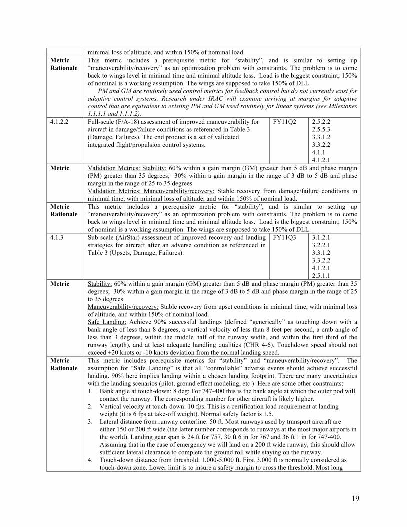
minimal loss of altitude, and within 150% of nominal load. Metric This metric includes a prerequisite metric for “stability”, and is similar to setting up Rationale “maneuverability/recovery” as an optimization problem with constraints. The problem is to come
back to wings level in minimal time and minimal altitude loss. Load is the biggest constraint; 150% of nominal is a working assumption. The wings are supposed to take 150% of DLL.
PM and GM are routinely used control metrics for feedback control but do not currently exist for adaptive control systems. Research under IRAC will examine arriving at margins for adaptive control that are equivalent to existing PM and GM used routinely for linear systems (see Milestones 1.1.1.1 and 1.1.1.2).
4.1.2.2 Full-scale (F/A-18) assessment of improved maneuverability for FY11Q2 2.5.2.2 aircraft in damage/failure conditions as referenced in Table 3 2.5.5.3 (Damage, Failures). The end product is a set of validated 3.3.1.2 integrated flight/propulsion control systems. 3.3.2.2
4.1.1 4.1.2.1
Metric Validation Metrics: Stability: 60% within a gain margin (GM) greater than 5 dB and phase margin (PM) greater than 35 degrees; 30% within a gain margin in the range of 3 dB to 5 dB and phase margin in the range of 25 to 35 degrees Validation Metrics: Maneuverability/recovery: Stable recovery from damage/failure conditions in minimal time, with minimal loss of altitude, and within 150% of nominal load.
Metric This metric includes a prerequisite metric for “stability”, and is similar to setting up Rationale “maneuverability/recovery” as an optimization problem with constraints. The problem is to come
back to wings level in minimal time and minimal altitude loss. Load is the biggest constraint; 150% of nominal is a working assumption. The wings are supposed to take 150% of DLL.
4.1.3 Sub-scale (AirStar) assessment of improved recovery and landing FY11Q3 3.1.2.1 strategies for aircraft after an adverse condition as referenced in 3.2.2.1 Table 3 (Upsets, Damage, Failures). 3.3.1.2
3.3.2.2 4.1.2.1 2.5.1.1
Metric Stability: 60% within a gain margin (GM) greater than 5 dB and phase margin (PM) greater than 35 degrees; 30% within a gain margin in the range of 3 dB to 5 dB and phase margin in the range of 25 to 35 degrees Maneuverability/recovery: Stable recovery from upset conditions in minimal time, with minimal loss of altitude, and within 150% of nominal load. Safe Landing: Achieve 90% successful landings (defined “generically” as touching down with a bank angle of less than 8 degrees, a vertical velocity of less than 8 feet per second, a crab angle of less than 3 degrees, within the middle half of the runway width, and within the first third of the runway length), and at least adequate handling qualities (CHR 4-6). Touchdown speed should not exceed +20 knots or -10 knots deviation from the normal landing speed.
Metric Rationale
This metric includes prerequisite metrics for “stability” and “maneuverability/recovery”. The assumption for “Safe Landing” is that all “controllable” adverse events should achieve successful landing. 90% here implies landing within a chosen landing footprint. There are many uncertainties with the landing scenarios (pilot, ground effect modeling, etc.) Here are some other constraints: 1. Bank angle at touch-down: 8 deg: For 747-400 this is the bank angle at which the outer pod will
contact the runway. The corresponding number for other aircraft is likely higher. 2. Vertical velocity at touch-down: 10 fps. This is a certification load requirement at landing
weight (it is 6 fps at take-off weight). Normal safety factor is 1.5. 3. Lateral distance from runway centerline: 50 ft. Most runways used by transport aircraft are
either 150 or 200 ft wide (the latter number corresponds to runways at the most major airports in the world). Landing gear span is 24 ft for 757, 30 ft 6 in for 767 and 36 ft 1 in for 747-400. Assuming that in the case of emergency we will land on a 200 ft wide runway, this should allow sufficient lateral clearance to complete the ground roll while staying on the runway.
4. Touch-down distance from threshold: 1,000-5,000 ft. First 3,000 ft is normally considered as touch-down zone. Lower limit is to insure a safety margin to cross the threshold. Most long
19
runways are 12,000 - 14,000 ft. Therefore, touching down with 7,000-9,000 ft to spare should be sufficient.
IRAC 4.2 Systems Analysis for Robust Configurations
Adaptive control can only provide the performance that is achievable for a given system. If the adverse conditions faced by the aircraft are such that the available control authority cannot provide the capability to safely fly and land the aircraft, then no amount of control adaptation will be able to provide safe control of the aircraft. Systems Analysis for Robust Configurations (SARC) will focus on determining:
1. The type of adverse events that can be accommodated by control adaptation alone. 2. The type of adverse events requiring modifications in the various subsystems impacting
flight and propulsion control in order to maintain adequate authority for safe flight.
As part of (1) above, the analysis will provide a list of potential adverse event scenarios against which the approaches for flight, propulsion and mission adaptive control can be evaluated. These approaches will incorporate data from a variety of sources, including but not limited to the National Transportation Safety Board (NTSB), Aviation Safety Reporting System (ASRS), and Aviation Safety Information and Sharing (ASIAS). Recent advances in data mining research performed in the Integrated Vehicle Health Management Project will also be leveraged to provide statistical data for large transport class aircraft (milestone MMT.08-1 2.2.5). Specifically, SARC is interested in reports, incidents, and data (statistical and prognostic) associated with loss-of-control (LOC), system/component failure or malfunction – non powerplant (SCF-NP), system/component failure or malfunction – powerplant (SFC-PP), and icing (ICE). The data of interest would include the flight condition, aircraft type, aircraft state, type of adverse event, and condition of the control surfaces and powerplants. This data will be used for three purposes:
• To support requirements assessment, including a Key Decision Point in FY07Q4 regarding the potential for adaptive control systems to impact icing related accidents.*
• To refine the initial set of adverse conditions in Table 3 that will be examined in simulation and sub- and full-scale validation/assessment (Level 3 and 4) milestones.
• To assess the potential benefit of IRAC technology on future fatal accident rate
*Based on the findings of an internal IRAC study, IRAC project has included both airframe and engine icing research into the project portfolio. These are highlighted by the inclusion of three key milestones listed under Level 2 and Level 1 milestones.
As part of (2), SARC will focus on conducting analyses to determine what kind of modifications can be made in the various subsystems impacting flight and propulsion control in order to maintain adequate authority for safe aircraft control. The analyses will include the impact of these modifications on the overall system and will be coordinated with those activities under the Dynamics and Controls element of the Subsonic Fixed Wing project that are looking at innovative control effectors. Milestones are provided below, and support Level 4.2 Technology Portfolio Assessment. Supporting material is also provided in Appendix D.
20
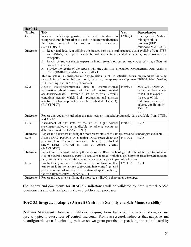
IRAC 4.2 Number Title Year Dependencies 4.2.1 Review statistical/prognostic data and literature to
interpret/extract information to establish future requirements for icing research for subsonic civil transports (WAYPOINT)
FY07Q4 Leverages IVHM data mining work in-progress (IIFD milestone MMT.08-1)
Outcome 1. Report and document utilizing the most current statistical/prognostic data available from NTSB and ASIAS, the reports, incidents, and accidents associated with icing for subsonic civil transports.
2. Report by subject matter experts in icing research on current knowledge of icing effects on control parameters.
3. Provide the results of the reports with the Joint Implementation Measurement Data Analysis Team (JIMDAT) and document feedback.
This milestone is considered a “Key Decision Point” to establish future requirements for icing research for subsonic civil transports, including the appropriate alignment (IVHM: identification, IIFD: sensing, and IRAC: flight control)
4.2.2 Review statistical/prognostic data to interpret/extract information about causes of loss of control related accidents/incidents. Develop a list of potential adverse conditions against which flight, propulsion and mission adaptive control approaches can be evaluated (Table 3). (WAYPOINT)
FY08Q4 MMT.08-1 (Note: A request has been made to IVHM to expand the scope of this milestone to include adverse conditions in Table 3) 4.2.1
Outcome Report and document utilizing the most current statistical/prognostic data available from NTSB, and ASIAS.
4.2.3 Assessment of the state of the art of flight control systems/technologies as applicable to adverse events as determined in 4.2.2. (WAYPOINT)
FY09Q2 4.2.2
Outcome Report and document utilizing the most recent state of the art systems and technologies available. 4.2.4 Assess IRAC portfolio by mapping IRAC research to the
potential loss of control scenarios. Identify overlooked safety issues involved in loss of control events. (WAYPOINT)
FY10Q2 4.2.3
Outcome Report and document, utilizing the most recent IRAC technologies developed to map to potential loss of control scenarios. Portfolio analyses metrics: technical development risk; implementation risk; fatal accident rate; safety benefit/costs; and project impact of safety risk.
4.2.5 Conduct analyses that will determine the modifications that can be made in the various subsystems impacting flight and propulsion control in order to maintain adequate authority for safe aircraft control. (WAYPOINT)
FY11Q3 4.2.4
Outcome Report and document utilizing the most recent IRAC technologies developed.
The reports and documents for IRAC 4.2 milestones will be validated by both internal NASA requirements and external peer reviewed publication processes.
IRAC 3.1 Integrated Adaptive Aircraft Control for Stability and Safe Maneuverability
Problem Statement: Adverse conditions, ranging from faults and failures to damages and upsets, typically cause loss of control incidents. Previous research indicates that adaptive and reconfigurable control technologies have shown great promise in providing inner-loop stability
21
and in enabling higher maneuverability margins in damage conditions. Adaptive aircraft control implies integrated flight and propulsion control subject to static and dynamic structural constraints, a potentially reduced performance envelope, and reduced control power available in the presence of a fault, damage, or upset condition. Ensuring vehicle and system stability is the highest priority throughout upset prevention and/or recovery. Stability, maneuverability, and safe landing of a damaged vehicle are akin to the basic tenet of flying stated as “aviate, navigate, and communicate.” Once the vehicle is recovered from an upset, flying within a limited envelope (determined from an on-board capability assessment), with adequate performance and handling qualities now becomes primary. With more extreme failures, the ability to regain the performance of the fully functional (un-failed) system is compromised. When performance is sacrificed, a commensurate change in mission may be required. This requires interaction with the pilot or a higher-level mission manager or a guidance system (intelligent flight planning and guidance). The goal of "Integrated adaptive aircraft control for stability and safe maneuverability" is to arrive at validated adaptive control designs and recovery strategies that are applicable to current and future aircraft.
Research Approach: The research approach will be to first investigate mathematical characterizations and formulations of the control problems under adverse conditions, including: failures (actuators, sensors, propulsion, and other components); dynamics changes due to physical changes resulting from structural damage, fatigue crack growth, etc.; and nonlinear behavior associated with abnormal regions of the flight envelope (state space). The adaptive control approaches to be investigated will include direct and indirect approaches as well as concepts from predictive optimal control and multivariable robust control theory. The final adaptive control architecture will likely consist of a multi-level hybrid direct-indirect controller with an intelligent supervisory component. Mathematical rigor will be greatly emphasized in order to obtain theoretical guarantees of signal boundedness and convergence where possible. This research is expected to advance the state of the art in basic adaptive systems science and will also have broader applicability, not only to a new generation of aircraft, but also to exploration activities. Key research components include provably convergent adaptive control methods, on-line state estimation, close integration of aerodynamic and propulsive control effectors, static and dynamic structural modeling adequate for on-board implementation, validated handling qualities, stability and performance metrics for damaged vehicles, and improved engine response times that allow a real-time trade off between engine life and performance.
Technology Validation Strategy: Technology validation at Level 3 consists of laboratory tests, fixed-base and/or motion-based simulation, subscale, and full-scale F/A-18 tests to verify expected performance and uncover implementation issues associated with integration. These experiments serve as a proving ground, whereby those elements that meet the expected performance metrics and are deemed sufficiently mature will be promoted to Level 4 validation. F/A-18 flight-testing will also help identify implementation issues associated with Level 4 assessment/validation.
Milestones:
IRAC 3.1.1 Number Title Year Dependencies
22
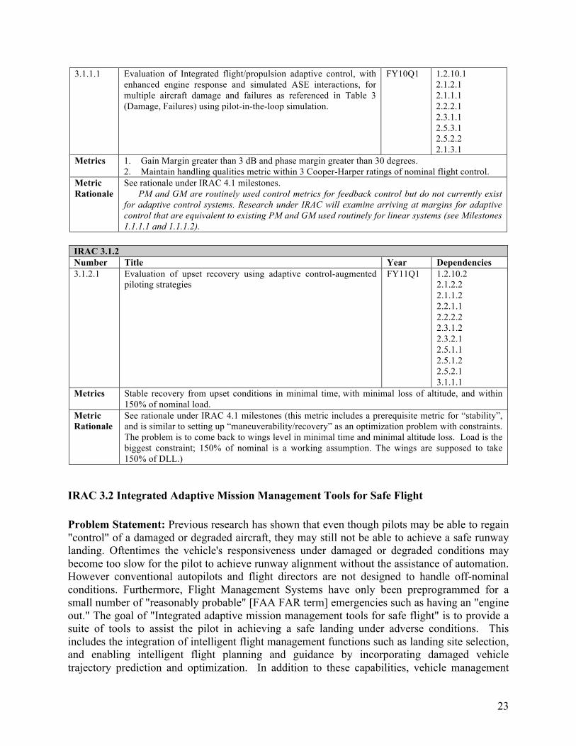
3.1.1.1 Evaluation of Integrated flight/propulsion adaptive control, with FY10Q1 1.2.10.1 enhanced engine response and simulated ASE interactions, for 2.1.2.1 multiple aircraft damage and failures as referenced in Table 3 2.1.1.1 (Damage, Failures) using pilot-in-the-loop simulation. 2.2.2.1
2.3.1.1 2.5.3.1 2.5.2.2 2.1.3.1
Metrics 1. Gain Margin greater than 3 dB and phase margin greater than 30 degrees. 2. Maintain handling qualities metric within 3 Cooper-Harper ratings of nominal flight control.
Metric See rationale under IRAC 4.1 milestones. Rationale PM and GM are routinely used control metrics for feedback control but do not currently exist
for adaptive control systems. Research under IRAC will examine arriving at margins for adaptive control that are equivalent to existing PM and GM used routinely for linear systems (see Milestones 1.1.1.1 and 1.1.1.2).
IRAC 3.1.2 Number Title Year Dependencies 3.1.2.1 Evaluation of upset recovery using adaptive control-augmented
piloting strategies FY11Q1 1.2.10.2
2.1.2.2 2.1.1.2 2.2.1.1 2.2.2.2 2.3.1.2 2.3.2.1 2.5.1.1 2.5.1.2 2.5.2.1 3.1.1.1
Metrics Stable recovery from upset conditions in minimal time, with minimal loss of altitude, and within 150% of nominal load.
Metric Rationale
See rationale under IRAC 4.1 milestones (this metric includes a prerequisite metric for “stability”, and is similar to setting up “maneuverability/recovery” as an optimization problem with constraints. The problem is to come back to wings level in minimal time and minimal altitude loss. Load is the biggest constraint; 150% of nominal is a working assumption. The wings are supposed to take 150% of DLL.)
IRAC 3.2 Integrated Adaptive Mission Management Tools for Safe Flight
Problem Statement: Previous research has shown that even though pilots may be able to regain "control" of a damaged or degraded aircraft, they may still not be able to achieve a safe runway landing. Oftentimes the vehicle's responsiveness under damaged or degraded conditions may become too slow for the pilot to achieve runway alignment without the assistance of automation. However conventional autopilots and flight directors are not designed to handle off-nominal conditions. Furthermore, Flight Management Systems have only been preprogrammed for a small number of "reasonably probable" [FAA FAR term] emergencies such as having an "engine out." The goal of "Integrated adaptive mission management tools for safe flight" is to provide a suite of tools to assist the pilot in achieving a safe landing under adverse conditions. This includes the integration of intelligent flight management functions such as landing site selection, and enabling intelligent flight planning and guidance by incorporating damaged vehicle trajectory prediction and optimization. In addition to these capabilities, vehicle management
23
functions will be necessary to coordinate the roles and responsibilities between adaptive flight, propulsion, and airframe control systems.
Research Approach: This multi-disciplinary research effort will investigate how planning & scheduling and control agent concepts can be used to increase safety of flight under emergency situations caused by adverse conditions. Specific research areas will include the integration of adaptive flight, propulsion and structural control systems with intelligent flight planning and guidance to provide flight management capabilities that can accommodate adapting levels of maneuvering performance. Aircraft structural and engine health assessments will also be used, along with additional Integrated Vehicle Health Management information, to determine their impact on flight capabilities and the level of urgency for an immediate landing.
Another significant aspect of this research will be the investigation of interactive planning and shared execution models, so the pilot can interact with the system by accepting or interactively manipulating recommended trajectories. Furthermore, the pilot will be able to offload some of the necessary actions to the autonomy in time-critical situations (or in cases with a danger of incapacitation). This effort will leverage research efforts in the Integrated Intelligent Flight Deck Project to identify which methods of interaction would be most beneficial to the pilot.
Key research components include provably convergent adaptive planning and guidance methods and algorithms, interactive and mixed-initiative planning with variable levels of autonomy, hybrid system concepts for flight and vehicle management for preventing and recovering from aircraft loss of control.
Technology Validation Strategy: Technology validation at Level 3 consists of laboratory tests, fixed-base and/or motion-based simulation, and subscale, and full-scale F/A-18 tests to verify expected performance and uncover implementation issues associated with integration. These experiments serve as a proving ground, whereby those elements that meet the expected performance metrics and are deemed sufficiently mature will be promoted to Level 4 validation. F/A-18 flight-testing will also help in identify implementation issues associated with Level 4 assessment/validation.
Milestones:
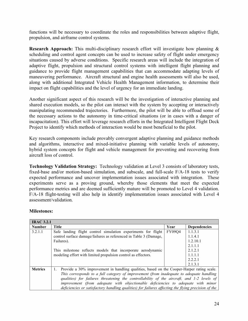
IRAC 3.2.1 Number Title Year Dependencies 3.2.1.1 Safe landing flight control simulation experiments for flight
control surface damage/failures as referenced in Table 3 (Damage, Failures).
This milestone reflects models that incorporate aerodynamic modeling effort with limited propulsion control as effectors.
FY09Q4 1.1.3.1 1.1.4.1 1.2.10.1 2.1.1.1 2.1.2.1 1.1.1.1 2.2.2.1 2.1.3.1
Metrics 1. Provide a 30% improvement in handling qualities, based on the Cooper-Harper rating scale. This corresponds to a full category of improvement (from inadequate to adequate handling qualities) for failures threatening the controllability of the aircraft, and 1-2 levels of improvement (from adequate with objectionable deficiencies to adequate with minor deficiencies or satisfactory handling qualities) for failures affecting the flying precision of the
24
aircraft. 2. Achieve 90% successful landings (defined generically as touching down with a bank angle of
less than 8 degrees, a vertical velocity of less than 8 feet per second, a crab angle of less than 3 degrees, within the middle half of the runway width, and within the first third of the runway length), and at least adequate handling qualities (CHR 4-6). Touchdown speed should not exceed +20 knots or -10 knots deviation from the normal landing speed.
Metric Rationale
See rationale under IRAC 4.1 milestones.
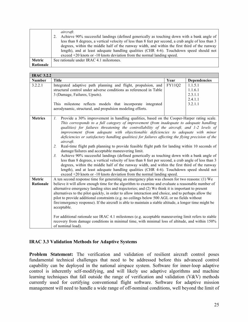
IRAC 3.2.2 Number Title Year Dependencies 3.2.2.1 Integrated adaptive path planning and flight, propulsion, and FY11Q2 1.1.5.1
structural control under adverse conditions as referenced in Table 1.1.6.1 3 (Damage, Failures, Upsets). 2.3.1.1
2.4.1.1 This milestone reflects models that incorporate integrated aerodynamic, structural, and propulsion modeling efforts.
3.2.1.1
Metrics 1. Provide a 30% improvement in handling qualities, based on the Cooper-Harper rating scale. This corresponds to a full category of improvement (from inadequate to adequate handling qualities) for failures threatening the controllability of the aircraft, and 1-2 levels of improvement (from adequate with objectionable deficiencies to adequate with minor deficiencies or satisfactory handling qualities) for failures affecting the flying precision of the aircraft.
2. Real-time flight path planning to provide feasible flight path for landing within 10 seconds of damage/failures and acceptable maneuvering limit.
3. Achieve 90% successful landings (defined generically as touching down with a bank angle of less than 8 degrees, a vertical velocity of less than 8 feet per second, a crab angle of less than 3 degrees, within the middle half of the runway width, and within the first third of the runway length), and at least adequate handling qualities (CHR 4-6). Touchdown speed should not exceed +20 knots or -10 knots deviation from the normal landing speed.
Metric A ten second response time for generating an emergency plan was chosen for two reasons: (1) We Rationale believe it will allow enough time for the algorithm to examine and evaluate a reasonable number of
alternative emergency landing sites and trajectories; and (2) We think it is important to present alternatives to the pilot quickly, in order to allow interaction and choice, and to perhaps allow the pilot to provide additional constraints (e.g. no ceilings below 500 AGL or no fields without fire/emergency response). If the aircraft is able to maintain a stable altitude, a longer time might be acceptable.
For additional rationale see IRAC 4.1 milestones (e.g. acceptable maneuvering limit refers to stable recovery from damage conditions in minimal time, with minimal loss of altitude, and within 150% of nominal load).
IRAC 3.3 Validation Methods for Adaptive Systems
Problem Statement: The verification and validation of resilient aircraft control poses fundamental technical challenges that need to be addressed before this advanced control capability can be deployed in the national airspace system. Software for inner-loop adaptive control is inherently self-modifying, and will likely use adaptive algorithms and machine learning techniques that fall outside the range of verification and validation (V&V) methods currently used for certifying conventional flight software. Software for adaptive mission management will need to handle a wide range of off-nominal conditions, well beyond the limit of
25
what can be preprogrammed in advance. This will require verification methods for intelligent algorithms for flight planning and coordinated vehicle management of aircraft with limited capabilities and degraded airframes and propulsion systems, and validation of algorithms that predict control augmentation needed for the landing configuration based on damage assessment and measurements prior to approach. As with conventional aircraft control or guidance systems, in-flight integrity monitoring of resilient control will be required for certification. Methods for verifying and testing the software can contribute techniques for this self-monitoring function during flight.
Research Approach: The research approach for V&V of adaptive systems involves an integrated mix of analysis and experimentation. Flight experiments alone can be used to demonstrate a technology without truly validating it, because the range of conditions exposed during a set of flight experiments is limited. Therefore, it is important to couple these experiments with analysis results on the system and its controller. For example, as detailed in Section 1.3, probabilistic methods are being developed to quantify the effect of uncertainty and establish confidence bounds on simulation predictions. Stability guarantees are also being employed in the design of the control architectures and algorithms. These guarantees necessarily abstract the physical system into an analysis-compatible form, making certain simplifying assumptions. The degree to which experimental conditions violate these assumptions is what ultimately determines the utility of control theoretic guarantees to system-level validation and verification. To gain this understanding requires a rich set of data from both open and closed loop flight experiments. Subscale flight-testing is seen as an important step towards this end. Subscale testing will provide the ability to fly different vehicle configurations, rapidly change control law algorithms, and enter into departed or other high-risk flight conditions. These experiments will be designed, to the extent possible, to expose features of the model or control algorithm where confidence is low and validation necessary. Techniques that are matured in this way will make full-scale testing more productive as some implementation issues will be resolved in subscale and these test results can also serve as a form of risk reduction.
Technology Validation Strategy: Technology validation at Level 3 consists of simulation analysis and related subscale flight tests to verify expected performance and uncover implementation issues associated with integration. These experiments serve as a proving ground, whereby those elements that meet the expected performance metrics and are deemed sufficiently mature will be promoted to Level 4 validation.
Milestones:
IRAC 3.3.1 Number Title Year Dependencies 3.3.1.1 Develop tools for system validation of adaptive flight control
systems. FY09Q4 2.1.1.1
2.5.5.1 2.5.4.1
Metric Extent to which stability of inner-loop adaptation and convergence processes can be guaranteed. By saying “Extent” we mean that we want to prove that the theoretical guarantees of adaptive control as researched in IRAC can be verified and guaranteed in software
26
3.3.1.2 Develop procedures for software verification and evaluation tools for system validation under experimental conditions (WAYPOINT).
FY11Q1 2.1.1.2 2.5.4.2 2.4.1.1 2.5.3.2 3.3.1.1 4.1.1
Outcome Documented recommendations, processes, and lessons-learned for the V&V of adaptive IRAC control systems
IRAC 3.3.2 Number Title Year Dependencies 3.3.2.1 Design and evaluate through simulation online integrity monitoring
for adaptive control systems FY09Q4 2.1.1.1
2.5.2.1 2.5.3.1 2.5.4.1
Metric Percent of monitoring defects detected by online integrity monitoring and percent of false positives. Milestone: 99% failure detection with less than 1% false positives.
3.3.2.2 Validate online integrity monitoring in relevant experimental conditions
FY11Q2 2.5.1.2. 2.5.4.2 2.5.3.2 3.3.2.1
Metric Time (in seconds) to predict loss of stability as flight parameters change using online integrity monitoring. Milestone: within 2 seconds
Metric Rationale
Transitioning the integrity monitoring technology into flight experiments requires making it operate near-real time and with the noise and measurement limitations inherent in experimental vehicles.
IRAC 2.0 Level 2 Disciplinary Research
This subsection describes the Level 2 disciplinary research elements of IRAC. Dependencies and successors associated with specific Level 2 elements are shown in the subsections within IRAC 2.1 through IRAC 2.5.
IRAC 2.1 Integrated Dynamics and Flight Control
IRAC 2.1.1 Adaptive Control Methods under Adverse Events
Problem Statement: An aircraft is a complex machine and contributing factors leading to typical loss of control situations are numerous. Strategies to tackle such a wide array of possible scenarios cannot be approached as point designs as is typically done in traditional control approaches. In addition, our understanding of aircraft response characteristics during a loss of control event is limited. Research in the area of adaptive/intelligent control has made significant progress and has seen some important milestones in the application to fault-adaptive aircraft control. Adaptive control and adaptive strategies by nature are not point designs. This gives us a tremendous advantage as a starting point for addressing the wide array of loss of control contributing factors.
27
Previous Related Research: Adaptive control of dynamic systems has been an active research area for several years and has traditionally addressed systems that have changing parameters and/or failures. While adaptive flight control has been much researched, it has not been universally adopted in the aviation industry due to a number of software, stability, and implementation issues. These issues stem from the fact that adaptive control research has not emphasized traditional control design issues such as stability margins and performance metrics such as rise time, settling time, etc. The lack of guaranteed stability and robustness under changing environments is a key challenge in adaptive control research. In addition, adaptive flight control research has not focused on the need for an integrated approach that respects system constraints posed by actuator limitations, aeroservoelastic interactions, and propulsion system constraints.
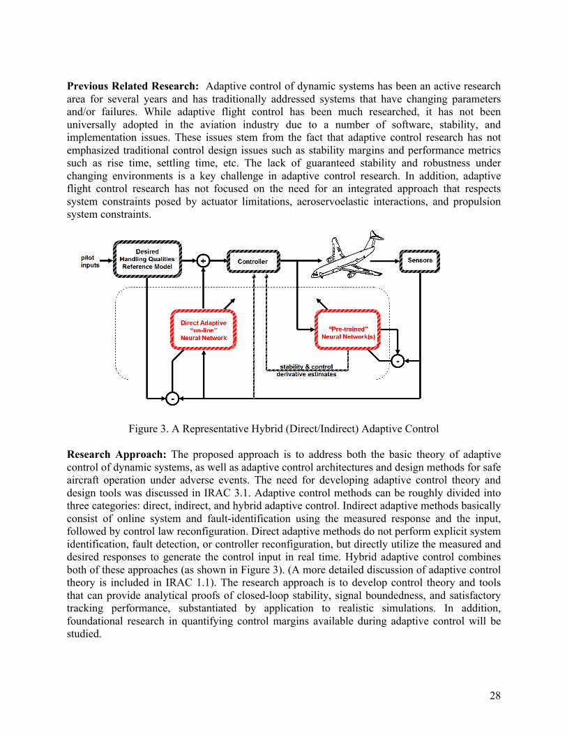
Figure 3. A Representative Hybrid (Direct/Indirect) Adaptive Control
Research Approach: The proposed approach is to address both the basic theory of adaptive control of dynamic systems, as well as adaptive control architectures and design methods for safe aircraft operation under adverse events. The need for developing adaptive control theory and design tools was discussed in IRAC 3.1. Adaptive control methods can be roughly divided into three categories: direct, indirect, and hybrid adaptive control. Indirect adaptive methods basically consist of online system and fault-identification using the measured response and the input, followed by control law reconfiguration. Direct adaptive methods do not perform explicit system identification, fault detection, or controller reconfiguration, but directly utilize the measured and desired responses to generate the control input in real time. Hybrid adaptive control combines both of these approaches (as shown in Figure 3). (A more detailed discussion of adaptive control theory is included in IRAC 1.1). The research approach is to develop control theory and tools that can provide analytical proofs of closed-loop stability, signal boundedness, and satisfactory tracking performance, substantiated by application to realistic simulations. In addition, foundational research in quantifying control margins available during adaptive control will be studied.
28
The adaptive control methods to be examined initially address various needs of resiliency. For example, reinforcement learning control along with a direct-adaptive neurocontrol approach will be investigated to accommodate the presence of static and dynamic saturation. Cross-coupling between longitudinal and lateral axes due to failures, damage, and varying time constants for adaptation will be investigated using a hybrid approach that combines system identification along with direct-adaptive control. On-line reconfiguration, especially achieving attitude control using propulsive forces and moments, will be investigated using adaptive critic based reinforcement learning approaches. Methods such as adaptive back-stepping will be investigated to address inherently nonlinear systems as well as the issues of time-scale separation, which is important for systems with different time latency such as engines. Although various methods will be examined for their strengths in solving different problems associated with resiliency, the intent is to examine the relative merits of these techniques in addressing many of the adverse conditions in a Monte Carlo sense at Level 2 and to validate the most promising of these techniques using flight and simulation tests.
Technology Validation Strategy: The performance of candidate control methods, tools, and algorithms will be evaluated under a specified set of dynamic changes, anomalies, and failures. Validation of these results will be accomplished through a combination of various analytical and experimental techniques. Analytical methods will require foundational extensions to validate stability and performance of controls systems containing adaptive components. For example, analytical methods that can handle large state space systems using guided Monte Carlo testing will be used to define critical test points that can be further scrutinized in simulation. Experimental validation techniques, including batch or manned simulations and hardware-in-the-loop simulations, will be used to complement and confirm the analytical methods. Simulations will be validated to ensure that the dynamics are represented with high fidelity. Experimental validation will also be done using sub-scale and full-scale flight test vehicles as appropriate. A key validation technique using simulations for integrated dynamic systems will provide validation tests of multiple components of the dynamic systems.
Milestones:
IRAC 2.1.1 Number Title Year Dependencies 2.1.1.1 Integrated initial adaptive schemes and algorithms for FY09Q3 1.1.1.1
effective control in the presence of selected anomaly, 1.1.2.1 uncertainty, and ASE interactions simulated as time 1.2.3.1 delays (acting as an additional disturbance); Candidate scheme(s) implemented on flight dynamics simulation for selected conditions. Selected conditions will represent the broad categories as listed in Table 3 with the intention of testing the boundaries of these categories. For example, under damage, we would like to see for what percentage of wing loss we can effectively control the vehicle.
1.2.3.3
Metric Stability, and performance under off-nominal conditions to be no worse than 40% of nominal (implying no adverse event) dynamic performance. The goal is to compare both time response and frequency response (such as rise time, overshoot, transient peak ratio, resonance peaks, magnitude and phase behavior, bandwidth) where possible.
2.1.1.2 Integrated advanced adaptive control schemes and algorithms for prevention/ recovery under selected
FY11Q1 2.1.1.1 2.1.2.1
29
adverse conditions; Candidate scheme(s) implemented on 1.1.5.1 flight dynamics simulation for selected test conditions as 1.1.1.2 elaborated in 2.1.1.1. 1.1.2.2
1.2.2.1 This milestone reflects a harder problem of addressing adaptive control schemes for adapting to integrated (aerodynamic, structural, and propulsion) efforts. Advanced methods are necessary to address multi-component dynamic failures as well as nonlinear, integrated flight dynamics that may result from the consideration of the integrated efforts.
1.2.3.2
Metric Stability, and performance under off-nominal conditions to be no worse than 40% of nominal dynamic performance. The goal is to compare both time response and frequency response (such as rise time, overshoot, transient peak ratio, resonance peaks, magnitude and phase behavior, bandwidth) where possible.
IRAC 2.1.2 Aircraft Modeling Methods for Flight Control Development
Problem Statement: Development of control systems for aircraft that prevent loss of control or allow safe recovery from flight anomalies, such as component failures, damage, or upset conditions, require advanced mathematical models that allow effective analysis, design, and simulation. In order to properly define these models and accurately simulate aircraft under these flight anomalies, further development of experimental and computational modeling methods is required. In addition, integrating the various modeling technologies in aircraft simulations to reflect their dynamic coupling has only been accomplished for limited and specialized cases. Current modeling and simulation technology does not account for coupled vehicle dynamics, aerodynamics with separated flows, structural dynamics including aeroelastic effects, and propulsion dynamics that enable the development of adaptive control technologies.
Previous Related Research: Experimental and computational modeling methods for aircraft under normal operating conditions are fairly successful and have been effectively applied to improve flight safety and performance. Prompted by military needs and flight safety, research over the past 2 decades has allowed modeling and simulation technology to advance and address conditions outside the normal operating environment. Programs such as the Air Force RESTORE Program, the DARPA-led X-31 Program, NASA’s High Alpha Technology Program, Aviation Safety and Security Program, Intelligent Flight Control System Program, and currently the NASA Fundamental Aero Program, contribute knowledge, tools, and capabilities to the IRAC program.
Research Approach: The proposed approach is to address modeling and simulation development in stages. As a practical matter, initial simulations for developing and evaluating control laws will represent basic rigid-body dynamics and include selected and limited flight anomaly models. This will allow the adaptive control technology development to begin using full simulations for testing. As advanced and improved experimental and computational models are developed that better characterize various anomalies, they will be incorporated into the full simulations. This work will take advantage of and be closely coordinated with the Subsonic Fixed-Wing Project where foundational work in nonlinear modeling for aircraft is being conducted. Experimental-based modeling methods will take advantage of current research in indicial functions as well as extensions to conventional aerodynamic models where appropriate.
30
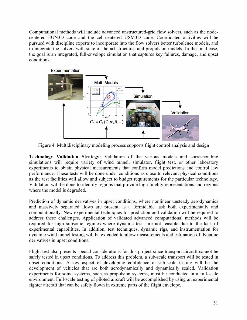
Computational methods will include advanced unstructured-grid flow solvers, such as the node-centered FUN3D code and the cell-centered USM3D code. Coordinated activities will be pursued with discipline experts to incorporate into the flow solvers better turbulence models, and to integrate the solvers with state-of-the-art structures and propulsion models. In the final case, the goal is an integrated, full-envelope simulation that captures key failures, damage, and upset conditions.
Figure 4. Multidisciplinary modeling process supports flight control analysis and design
Technology Validation Strategy: Validation of the various models and corresponding simulations will require variety of wind tunnel, simulator, flight test, or other laboratory experiments to obtain physical measurements that confirm model predictions and control law performance. These tests will be done under conditions as close to relevant physical conditions as the test facilities will allow and subject to budget requirements for the particular technology. Validation will be done to identify regions that provide high fidelity representations and regions where the model is degraded.
Prediction of dynamic derivatives in upset conditions, where nonlinear unsteady aerodynamics and massively separated flows are present, is a formidable task both experimentally and computationally. New experimental techniques for prediction and validation will be required to address these challenges. Application of validated advanced computational methods will be required for high subsonic regimes where dynamic tests are not feasible due to the lack of experimental capabilities. In addition, test techniques, dynamic rigs, and instrumentation for dynamic wind tunnel testing will be extended to allow measurements and estimation of dynamic derivatives in upset conditions.
Flight test also presents special considerations for this project since transport aircraft cannot be safely tested in upset conditions. To address this problem, a sub-scale transport will be tested in upset conditions. A key aspect of developing confidence in sub-scale testing will be the development of vehicles that are both aerodynamically and dynamically scaled. Validation experiments for some systems, such as propulsion systems, must be conducted in a full-scale environment. Full-scale testing of piloted aircraft will be accomplished by using an experimental fighter aircraft that can be safely flown in extreme parts of the flight envelope.
31
Physics-based models provide a way to test control algorithms in a Monte Carlo sense. For example, the effect of wing damage on controllability of the aircraft can be determined for test cases as a function a percentage of wing loss much more easily in simulation than using scaled models. It is understood that at first the models will be validated using a combination of wind tunnel and flight tests (see for example, Milestone 2.1.2.1 and 2.1.2.2). Once the models are validated for relevant test cases, the physics based models can be exercised beyond these validation points to better understand the benefits of adaptive control (see Milestones 2.1.1.2).
Milestones: IRAC 2.1.2 Number Title Year Dependencies 2.1.2.1 Candidate experimental and computational methods as identified FY09Q2 1.1.1.1
in Level 1 Modeling research will be implemented to model and 1.2.3.1 predict integrated aerodynamic, and structural characteristics for a rigid body aircraft for selected test conditions. Selected conditions will represent the broad categories as listed in Table 3 with the intention of testing the boundaries of these categories. For example, under damage, we would like to see for what percentage of wing loss we can effectively model the aerodynamic effects.
1.2.3.3
Metrics Demonstrate ability to predict aircraft responses within 30%, under adverse conditions. Predicted responses, produced by integrated 6-dof simulation, are compared against measured flight responses.
Metrics Rationale
Milestone 1.1.1.1 addresses metrics for adaptive control performance. This milestone will help us refine some of the initial estimates made on accuracies needed for modeling (see Milestones 2.1.2.1, 2.1.2.2, 2.3.1.1, and 2.3.1.2) to ensure stable adaptive controller performance.
2.1.2.2 Candidate experimental and computational methods as identified FY10Q3 1.1.1.1 in Level 1 Modeling research will be implemented to model and 1.2.2.1 predict integrated aerodynamic, aeroelastic, and structural 1.2.1.1 characteristics for test conditions as elaborated in 2.1.1.1. 1.2.3.2
Metrics Demonstrate ability to predict aircraft responses within 30%, under adverse conditions. Predicted responses, produced by integrated 6-dof simulation, are compared against measured flight responses with aeroelastic effects. Although this milestone addresses a more difficult problem by adding aeroelastic effects, the goal is to maintain the 30% performance envelope.
Metrics Rationale
The per cent figure represents an engineering estimate of permissible performance deterioration under worst-case scenario among the set of off-nominal conditions to be considered. This number may change to reflect new findings as the research progresses.
IRAC 2.1.3 Number Title Year Dependencies 2.1.3.1 Candidate computational methods implemented to model and
predict iced airframe aerodynamics for selected full scale aircraft configurations and flight conditions.
FY09Q4 1.2.10.1
Metrics CFD-predicted aerodynamic coefficients for full-scale iced airframe with selected ice shapes are available for integration into desktop and full-mission flight simulator. Ice shapes selected as reference shapes for those used in subscale modeling and testing.
Metrics Rationale
This work is being done to provide information about icing and its effects at full scale. No qualitative metrics are given because no full-scale data are available for validation. However, the work done here will be used as a basis (in particular, the ice shapes) for a related subscale study (MS 2.1.3.2). The subscale effort will produce validation data, but those data will not be directly applicable to this full-scale work. There are no proven methods to scale icing and its effects over a 20:1 scaling range. The subscale effort will, however, provide an opportunity in
32
the future to examine the computational methods employed here. 2.1.3.2 Candidate experimental and computational methods
implemented to model and predict iced airframe aerodynamics for selected subscale aircraft configurations and flight conditions.
FY10Q3 2.1.3.1
Metrics Predict, using CFD methods, iced airframe aerodynamic coefficients within 30% of those obtained in wind tunnel testing for selected subscale iced-aircraft configurations and conditions.
IRAC 2.2 Integrated Propulsion Control and Dynamics
Problem Statement: Previous research studies and field incident reports show that the propulsion system can be an effective tool to help control and land a damaged aircraft safely. Building upon NASA’s flight-proven Propulsion Controlled Aircraft (PCA) development, the Integrated Propulsion Controls and Dynamics (IPCD) research will focus on how the current and future propulsion control systems can be integrated and operated to improve the recovery and safe-landing of aircraft under adverse conditions.
Gas turbine engines are designed to provide sufficient safety margins to guarantee robust operation with an exceptionally long life. This is achieved in part by the control logic embedded in Full Authority Digital Engine Controller (FADEC) which combines state-of-the-art computer technologies with sensor and actuator technologies to ensure reliable, robust engine operation over a wide range of operating conditions. The FADEC and its control laws are designed to optimize the fuel efficiency while maintaining conservative operating margins to provide safe and long on-wing engine operation under normal operating conditions.
In an adverse condition, the engines may be required to be used as effectors to achieve stability and control augmentation. In some scenarios, the conservative margins limit the achievable engine performance and prevent the use of the engine as an effective control effector to recover the aircraft. Thus during adverse flight conditions, the conservative control of the engine to provide long usable life may no longer be in the best interest of overall aircraft safety, and it should be possible to “sacrifice” the engine to “save” the aircraft. In a preliminary study report under the NASA funded Damaged Aircraft Good Engine (DAGE) project, a severely damaged aircraft with 15% wing loss will require the engine to operate at its rated thrust level in order to be able to maintain its steady state condition at low altitude. The study also shows that an improvement in thrust response time (e.g. enhanced engine performance) from the typical 8 seconds to 6 seconds will have a huge impact on the maneuvering and handling of a damaged aircraft. This study has provided an initial guideline for the engine response requirement. However, a more thorough study on the engine performance requirements is needed under IRAC because the DAGE project focused only on damage to the wings.
This effort will primarily focus on developing concepts and control architectures that allow the engine to be used as an integrated part of the overall flight control system, responding to both the pilot and automated systems. Requirements for thrust response under adverse conditions (damage, failures, and upsets) will be examined as part of an integrated flight-propulsion control system. Finally, research will also include fundamental characteristic component damage models to assess the possible safety risk from both integrated and enhanced engine performance.
33
Previous Related Research: Previous Propulsion Controlled Aircraft (PCA) related research conducted by NASA has demonstrated the effectiveness of using engine thrust for control in adverse conditions. NASA PCA research also established requirements for dynamic engine performance to improve handling qualities for different landing scenarios. As part of NASA’s Aviation Safety & Security Program (AvSSP), the, “Damaged Aircraft Good Engine (DAGE)” project performed an initial study of the requirements for engine performance for damaged aircraft. Another AvSSP project, “Commercial Engine Damage Assessment and Recovery (CEDAR),” also addressed the possible extended operation of damaged engines by relaxing the controller constraints. NASA’s past research in the High Stability Engine Control (HISTEC) program provided some initial study on stability management and possible on-line estimation of stability margins. These study results will be directly applicable to the propulsion research under IRAC.
Research Approach: The long-term objective of the propulsion research under IRAC is to develop an enhanced engine capability to enable a fully integrated flight-propulsion control system for safe operation and landing of aircraft under adverse conditions. The interaction between the adaptive flight control and the enhanced propulsion control is envisioned to be as follows: i) the adaptive flight control receives information from the enhanced engine system on the achievable performance for safe operation over a given length of time; ii) the adaptive flight control generates commands to the engine control which are within achievable performance; iii) the engine control is adapted to provide the response commanded by the flight control.
To achieve this objective, research will be conducted in the following areas: 1. Flight test data collection for improved dynamic modeling of engine performance over
the broad flight envelope. 2. Definition of high level engine integration and performance requirements through flight
simulation; 3. Development of control strategies for integrated engine operation; 4. Development of control strategies for safe engine performance improvement; 5. Evaluation of control strategies via flight simulation (based on integration and
performance requirements), including on-line prognosis capability for engine operations.
Technology Validation Strategy: Technology development and validation follows a methodical approach to collect critical flight data to validate engine dynamics models, integrate the dynamics models into a realistic simulation, examine the requirements for the integration of flight-propulsion control and the requirements for engine response characteristics, and develop/evaluate associated control laws. Experimental testing on the material level will be used to validate lifing models required for on-line prognosis capability for safe engine operation. These lifing models will be integrated with the validated engine simulation to ensure that the thrust response improvement is achievable for the desired length of engine operation. Effectiveness of enhanced engine performance will be evaluated in an integrated flight and propulsion control simulation. The goal of the modeling effort is to enable a generic integrated flight-propulsion control approach that is applicable to a number of propulsion/ flight control
34
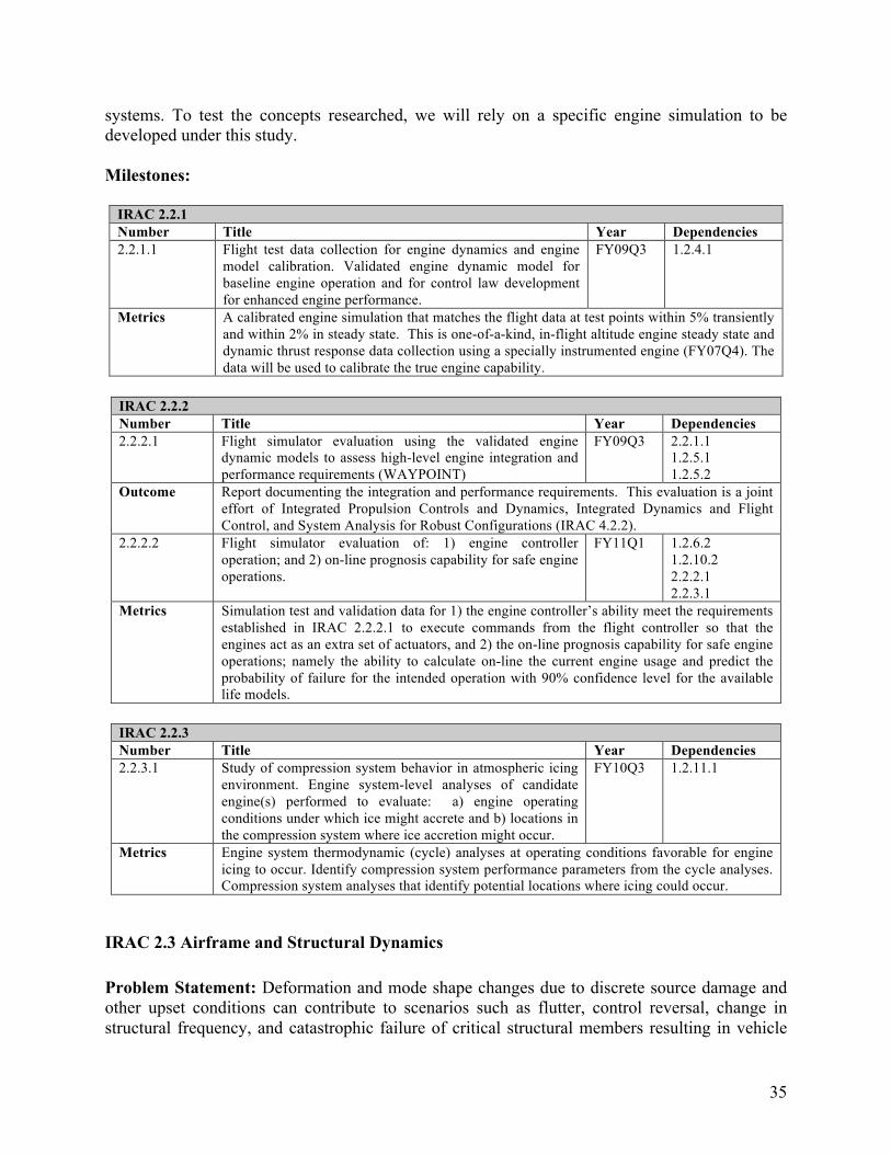
systems. To test the concepts researched, we will rely on a specific engine simulation to be developed under this study.
Milestones:
IRAC 2.2.1 Number Title Year Dependencies 2.2.1.1 Flight test data collection for engine dynamics and engine
model calibration. Validated engine dynamic model for baseline engine operation and for control law development for enhanced engine performance.
FY09Q3 1.2.4.1
Metrics A calibrated engine simulation that matches the flight data at test points within 5% transiently and within 2% in steady state. This is one-of-a-kind, in-flight altitude engine steady state and dynamic thrust response data collection using a specially instrumented engine (FY07Q4). The data will be used to calibrate the true engine capability.
IRAC 2.2.2 Number Title Year Dependencies 2.2.2.1 Flight simulator evaluation using the validated engine
dynamic models to assess high-level engine integration and performance requirements (WAYPOINT)
FY09Q3 2.2.1.1 1.2.5.1 1.2.5.2
Outcome Report documenting the integration and performance requirements. This evaluation is a joint effort of Integrated Propulsion Controls and Dynamics, Integrated Dynamics and Flight Control, and System Analysis for Robust Configurations (IRAC 4.2.2).
2.2.2.2 Flight simulator evaluation of: 1) engine controller operation; and 2) on-line prognosis capability for safe engine operations.
FY11Q1 1.2.6.2 1.2.10.2 2.2.2.1 2.2.3.1
Metrics Simulation test and validation data for 1) the engine controller’s ability meet the requirements established in IRAC 2.2.2.1 to execute commands from the flight controller so that the engines act as an extra set of actuators, and 2) the on-line prognosis capability for safe engine operations; namely the ability to calculate on-line the current engine usage and predict the probability of failure for the intended operation with 90% confidence level for the available life models.
IRAC 2.2.3 Number Title Year Dependencies 2.2.3.1 Study of compression system behavior in atmospheric icing
environment. Engine system-level analyses of candidate engine(s) performed to evaluate: a) engine operating conditions under which ice might accrete and b) locations in the compression system where ice accretion might occur.
FY10Q3 1.2.11.1
Metrics Engine system thermodynamic (cycle) analyses at operating conditions favorable for engine icing to occur. Identify compression system performance parameters from the cycle analyses. Compression system analyses that identify potential locations where icing could occur.
IRAC 2.3 Airframe and Structural Dynamics
Problem Statement: Deformation and mode shape changes due to discrete source damage and other upset conditions can contribute to scenarios such as flutter, control reversal, change in structural frequency, and catastrophic failure of critical structural members resulting in vehicle
35
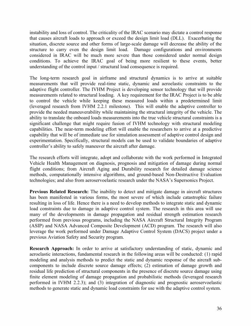
instability and loss of control. The criticality of the IRAC scenario may dictate a control response that causes aircraft loads to approach or exceed the design limit load (DLL). Exacerbating the situation, discrete source and other forms of large-scale damage will decrease the ability of the structure to carry even the design limit load. Damage configurations and environments considered in IRAC will be much more severe than those considered under normal design conditions. To achieve the IRAC goal of being more resilient to these events, better understanding of the control input / structural load consequence is required.
The long-term research goal in airframe and structural dynamics is to arrive at suitable measurements that will provide real-time static, dynamic and aeroelastic constraints to the adaptive flight controller. The IVHM Project is developing sensor technology that will provide measurements related to structural loading. A key requirement for the IRAC Project is to be able to control the vehicle while keeping these measured loads within a predetermined limit (leveraged research from IVHM 2.2.1 milestone). This will enable the adaptive controller to provide the needed maneuverability while maintaining the structural integrity of the vehicle. The ability to translate the onboard loads measurements into the true vehicle structural constraints is a significant challenge that might require fusion of IVHM technology with structural modeling capabilities. The near-term modeling effort will enable the researchers to arrive at a predictive capability that will be of immediate use for simulation assessment of adaptive control design and experimentation. Specifically, structural models can be used to validate boundaries of adaptive controller’s ability to safely maneuver the aircraft after damage.
The research efforts will integrate, adopt and collaborate with the work performed in Integrated Vehicle Health Management on diagnosis, prognosis and mitigation of damage during normal flight conditions; from Aircraft Aging and Durability research for detailed damage science methods, computationally intensive algorithms, and ground-based Non-Destructive Evaluation technologies; and also from aeroservoelastic research under the NASA’s Supersonics Project.
Previous Related Research: The inability to detect and mitigate damage in aircraft structures has been manifested in various forms, the most severe of which include catastrophic failure resulting in loss of life. Hence there is a need to develop methods to integrate static and dynamic load constraints due to damage in adaptive control system. The research in this area will use many of the developments in damage propagation and residual strength estimation research performed from previous programs, including the NASA Aircraft Structural Integrity Program (ASIP) and NASA Advanced Composite Development (ACD) program. The research will also leverage the work performed under Damage Adaptive Control System (DACS) project under a previous Aviation Safety and Security program.
Research Approach: In order to arrive at satisfactory understanding of static, dynamic and aeroelastic interactions, fundamental research in the following areas will be conducted: (1) rapid modeling and analysis methods to predict the static and dynamic response of the aircraft sub-components to include discrete source damage effects; (2) estimation of damage growth and residual life prediction of structural components in the presence of discrete source damage using finite element modeling of damage propagation and probabilistic methods (leveraged research performed in IVHM 2.2.3); and (3) integration of diagnostic and prognostic aeroservoelastic methods to generate static and dynamic load constraints for use with the adaptive control system.
36
Technology Validation Strategy: Key metrics in airframe and structural dynamics research include the ability to predict and implement aeroservoelastic constraints in the adaptive control system. The goal is to determine frequency response and flutter constraints within 15% and load constraint within 20%. The key metrics will be validated in control experiments and in simulation testbed.
The metrics presented above are initial estimates (ref. [MM-9], “Flutter Suppression Control Law Design and Testing for Active Flexible Wing”, Section IRAC 1.2) of uncertainty bounds beyond which fixed-gain controllers might drive the aircraft system unstable. Improved estimates for these uncertainty bounds for adaptive control will be part of the foundational research that are planned to be carried out in the beginning of the project (specifically, Milestone 1.1.1.1).
Milestones:
IRAC 2.3.1 Number Title Year Dependencies 2.3.1.1 Integrated rapid modeling and analysis methods to generate
static and dynamic load constraints due to structural damage for adaptive control system. Leverage work performed under AAD and IVHM.
FY09Q3 1.1.1.1 1.2.7.1
Metrics Demonstrate the reduced order model can determine dynamic frequency response and flutter constraints within 15% of the values obtained using high fidelity finite element models of representative aircraft wings.
Metric Rationale
The metrics presented above are initial estimates (ref. [MM-9], Section IRAC 1.2) of uncertainty bounds beyond which fixed-gain controllers might drive the aircraft system unstable. Improved estimates for these uncertainty bounds for adaptive control will be part of the foundational research that are planned to be carried out in the beginning of the project (specifically, Milestone 1.1.1.1).
2.3.1.2 Integrated diagnostics and prognostics aeroservoelastic methods to generate static and dynamic load constraints due to structural damage for adaptive control system. Leverage work performed under AAD and IVHM.
FY11Q1 1.1.1.1 1.2.7.1 1.2.8.1 2.3.1.1
Metrics Demonstrate integration of diagnosis iFEM and prognosis xFEM methods to predict the static and dynamic design limit load change within 20% of the experimentally measured strength of a stiffened panel with damage.
IRAC 2.3.2 Number Title Year Dependencies 2.3.2.1 Integrate Probabilistic methods to estimate aeroelastic
structural constraints using uncertainties in damage size, damage location, material parameters and loading. Leverage work performed under AAD and IVHM
FY11Q1 1.2.8.1 1.2.9.1
Metrics Estimate the aeroelastic load constraint within 95% confidence interval.
IRAC 2.4 Intelligent Flight Planning and Guidance
Problem Statement: Previous research has shown that even though pilots may be able to regain "control" of a damaged or degraded aircraft, they may still not be able to achieve a safe runway landing. Oftentimes the vehicle's responsiveness may become too slow and unpredictable for the
37
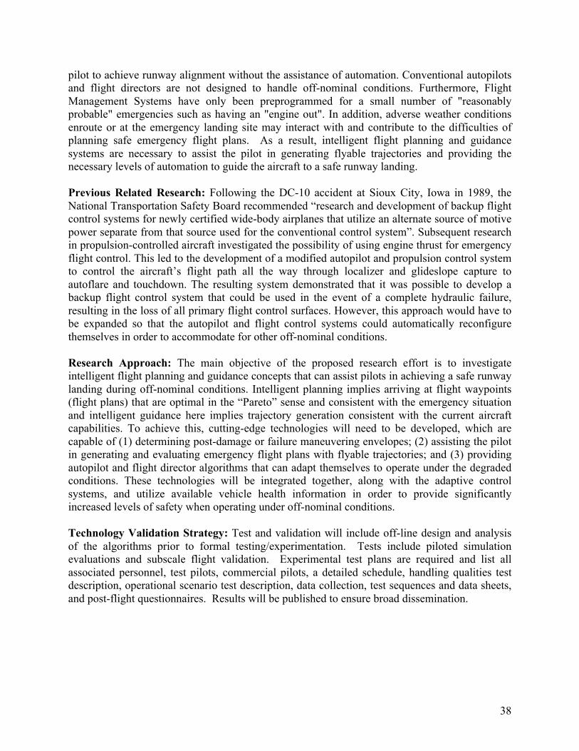
pilot to achieve runway alignment without the assistance of automation. Conventional autopilots and flight directors are not designed to handle off-nominal conditions. Furthermore, Flight Management Systems have only been preprogrammed for a small number of "reasonably probable" emergencies such as having an "engine out". In addition, adverse weather conditions enroute or at the emergency landing site may interact with and contribute to the difficulties of planning safe emergency flight plans. As a result, intelligent flight planning and guidance systems are necessary to assist the pilot in generating flyable trajectories and providing the necessary levels of automation to guide the aircraft to a safe runway landing.
Previous Related Research: Following the DC-10 accident at Sioux City, Iowa in 1989, the National Transportation Safety Board recommended “research and development of backup flight control systems for newly certified wide-body airplanes that utilize an alternate source of motive power separate from that source used for the conventional control system”. Subsequent research in propulsion-controlled aircraft investigated the possibility of using engine thrust for emergency flight control. This led to the development of a modified autopilot and propulsion control system to control the aircraft’s flight path all the way through localizer and glideslope capture to autoflare and touchdown. The resulting system demonstrated that it was possible to develop a backup flight control system that could be used in the event of a complete hydraulic failure, resulting in the loss of all primary flight control surfaces. However, this approach would have to be expanded so that the autopilot and flight control systems could automatically reconfigure themselves in order to accommodate for other off-nominal conditions.
Research Approach: The main objective of the proposed research effort is to investigate intelligent flight planning and guidance concepts that can assist pilots in achieving a safe runway landing during off-nominal conditions. Intelligent planning implies arriving at flight waypoints (flight plans) that are optimal in the “Pareto” sense and consistent with the emergency situation and intelligent guidance here implies trajectory generation consistent with the current aircraft capabilities. To achieve this, cutting-edge technologies will need to be developed, which are capable of (1) determining post-damage or failure maneuvering envelopes; (2) assisting the pilot in generating and evaluating emergency flight plans with flyable trajectories; and (3) providing autopilot and flight director algorithms that can adapt themselves to operate under the degraded conditions. These technologies will be integrated together, along with the adaptive control systems, and utilize available vehicle health information in order to provide significantly increased levels of safety when operating under off-nominal conditions.
Technology Validation Strategy: Test and validation will include off-line design and analysis of the algorithms prior to formal testing/experimentation. Tests include piloted simulation evaluations and subscale flight validation. Experimental test plans are required and list all associated personnel, test pilots, commercial pilots, a detailed schedule, handling qualities test description, operational scenario test description, data collection, test sequences and data sheets, and post-flight questionnaires. Results will be published to ensure broad dissemination.
38
Figure 5. Intelligent Flight Planning and Guidance with Adaptive Control Interactions
Milestone:
IRAC 2.4.1 Number Title Year Dependencies 2.4.1.1 Intelligent flight planning and guidance with maneuvering FY10Q4 1.1.3.1
envelope protection for test conditions as referenced in 1.1.4.1 Table 3 (Damage, Failures, Upsets). 1.1.5.1
1.1.1.1 1.1.2.1 1.2.2.1 1.2.4.1
Metrics Achieve 30% improvement in safety metrics, computed as a function of factors (such as duration of flight and maintaining desired safety margins), over pilot unaided.
Metrics The safety metrics will consist of weighted parameters that can be chosen by the pilot to take Rationale into account various safety factors for a given situation. These factors will include
maintaining structural, propulsion, and control limit margins as well as accounting for factors such as duration of flight, weather and runway conditions, and emergency facilities. The measurement of decision-quality is inherently time-dependent. When immediate decisions are required, planning tools should provide a substantial benefit. However, as pilots have more time available to plan, this benefit should converge to a minimum point that reflects the details involved in establishing planning quality and robustness. Our goal is to provide a distinguishable 30% improvement over pilot unaided performance.
IRAC 2.5 Verification and Validation Methods and Testbeds
Problem Statement: The development and implementation of IRAC technologies involves adaptive and possibly nondeterministic algorithms controlling the operation of safety-critical avionics under abnormal flight conditions. The complexity and criticality of this environment places a large burden on validation and verification efforts. New techniques are needed in experimentation, analysis, and software implementation in order to successfully mature these technologies.
Previous Related Research: Previous work in aviation safety has led to a better understanding of flight dynamics in abnormal flight conditions. Loss of control conditions, which can both lead to and be caused by system failures, were examined in the Control and Upset Management
39
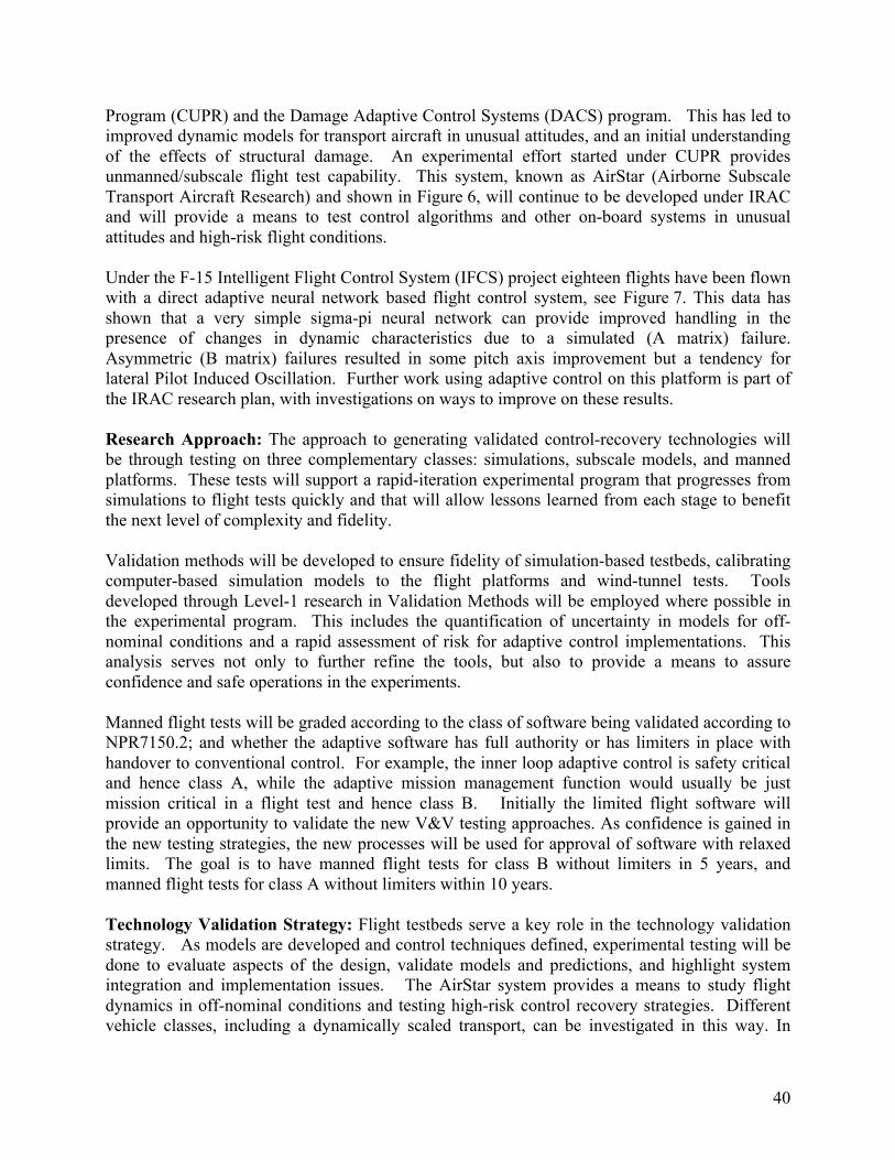
Program (CUPR) and the Damage Adaptive Control Systems (DACS) program. This has led to improved dynamic models for transport aircraft in unusual attitudes, and an initial understanding of the effects of structural damage. An experimental effort started under CUPR provides unmanned/subscale flight test capability. This system, known as AirStar (Airborne Subscale Transport Aircraft Research) and shown in Figure 6, will continue to be developed under IRAC and will provide a means to test control algorithms and other on-board systems in unusual attitudes and high-risk flight conditions.
Under the F-15 Intelligent Flight Control System (IFCS) project eighteen flights have been flown with a direct adaptive neural network based flight control system, see Figure 7. This data has shown that a very simple sigma-pi neural network can provide improved handling in the presence of changes in dynamic characteristics due to a simulated (A matrix) failure. Asymmetric (B matrix) failures resulted in some pitch axis improvement but a tendency for lateral Pilot Induced Oscillation. Further work using adaptive control on this platform is part of the IRAC research plan, with investigations on ways to improve on these results.
Research Approach: The approach to generating validated control-recovery technologies will be through testing on three complementary classes: simulations, subscale models, and manned platforms. These tests will support a rapid-iteration experimental program that progresses from simulations to flight tests quickly and that will allow lessons learned from each stage to benefit the next level of complexity and fidelity.
Validation methods will be developed to ensure fidelity of simulation-based testbeds, calibrating computer-based simulation models to the flight platforms and wind-tunnel tests. Tools developed through Level-1 research in Validation Methods will be employed where possible in the experimental program. This includes the quantification of uncertainty in models for off-nominal conditions and a rapid assessment of risk for adaptive control implementations. This analysis serves not only to further refine the tools, but also to provide a means to assure confidence and safe operations in the experiments.
Manned flight tests will be graded according to the class of software being validated according to NPR7150.2; and whether the adaptive software has full authority or has limiters in place with handover to conventional control. For example, the inner loop adaptive control is safety critical and hence class A, while the adaptive mission management function would usually be just mission critical in a flight test and hence class B. Initially the limited flight software will provide an opportunity to validate the new V&V testing approaches. As confidence is gained in the new testing strategies, the new processes will be used for approval of software with relaxed limits. The goal is to have manned flight tests for class B without limiters in 5 years, and manned flight tests for class A without limiters within 10 years.
Technology Validation Strategy: Flight testbeds serve a key role in the technology validation strategy. As models are developed and control techniques defined, experimental testing will be done to evaluate aspects of the design, validate models and predictions, and highlight system integration and implementation issues. The AirStar system provides a means to study flight dynamics in off-nominal conditions and testing high-risk control recovery strategies. Different vehicle classes, including a dynamically scaled transport, can be investigated in this way. In
40
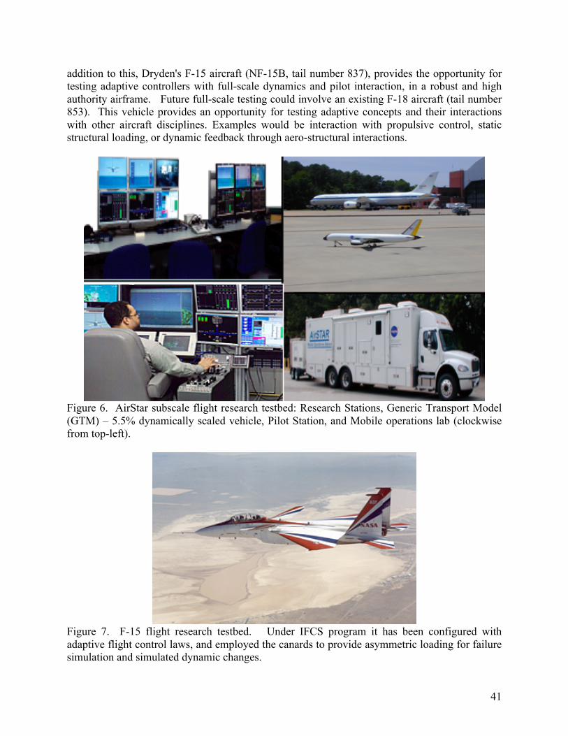
addition to this, Dryden's F-15 aircraft (NF-15B, tail number 837), provides the opportunity for testing adaptive controllers with full-scale dynamics and pilot interaction, in a robust and high authority airframe. Future full-scale testing could involve an existing F-18 aircraft (tail number 853). This vehicle provides an opportunity for testing adaptive concepts and their interactions with other aircraft disciplines. Examples would be interaction with propulsive control, static structural loading, or dynamic feedback through aero-structural interactions.
Figure 6. AirStar subscale flight research testbed: Research Stations, Generic Transport Model (GTM) – 5.5% dynamically scaled vehicle, Pilot Station, and Mobile operations lab (clockwise from top-left).
Figure 7. F-15 flight research testbed. Under IFCS program it has been configured with adaptive flight control laws, and employed the canards to provide asymmetric loading for failure simulation and simulated dynamic changes.
41
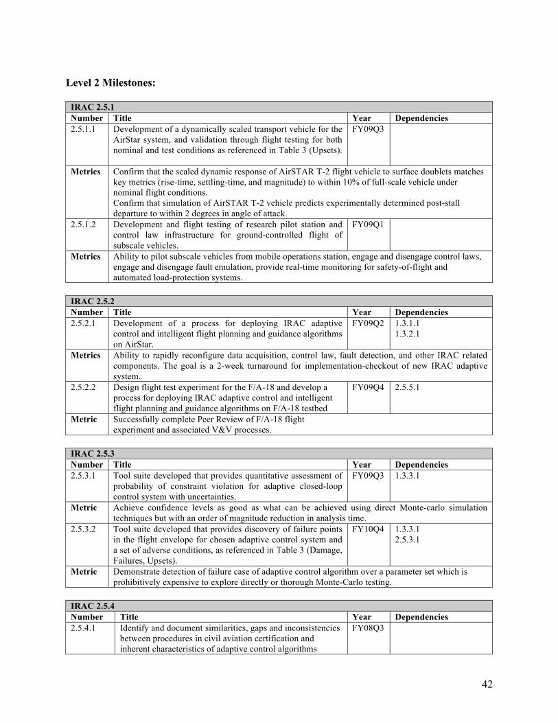
Level 2 Milestones:
IRAC 2.5.1 Number Title Year Dependencies 2.5.1.1 Development of a dynamically scaled transport vehicle for the
AirStar system, and validation through flight testing for both nominal and test conditions as referenced in Table 3 (Upsets).
FY09Q3
Metrics Confirm that the scaled dynamic response of AirSTAR T-2 flight vehicle to surface doublets matches key metrics (rise-time, settling-time, and magnitude) to within 10% of full-scale vehicle under nominal flight conditions. Confirm that simulation of AirSTAR T-2 vehicle predicts experimentally determined post-stall departure to within 2 degrees in angle of attack.
2.5.1.2 Development and flight testing of research pilot station and control law infrastructure for ground-controlled flight of subscale vehicles.
FY09Q1
Metrics Ability to pilot subscale vehicles from mobile operations station, engage and disengage control laws, engage and disengage fault emulation, provide real-time monitoring for safety-of-flight and automated load-protection systems.
IRAC 2.5.2 Number Title Year Dependencies 2.5.2.1 Development of a process for deploying IRAC adaptive
control and intelligent flight planning and guidance algorithms on AirStar.
FY09Q2 1.3.1.1 1.3.2.1
Metrics Ability to rapidly reconfigure data acquisition, control law, fault detection, and other IRAC related components. The goal is a 2-week turnaround for implementation-checkout of new IRAC adaptive system.
2.5.2.2 Design flight test experiment for the F/A-18 and develop a process for deploying IRAC adaptive control and intelligent flight planning and guidance algorithms on F/A-18 testbed
FY09Q4 2.5.5.1
Metric Successfully complete Peer Review of F/A-18 flight experiment and associated V&V processes.
IRAC 2.5.3 Number Title Year Dependencies 2.5.3.1 Tool suite developed that provides quantitative assessment of
probability of constraint violation for adaptive closed-loop control system with uncertainties.
FY09Q3 1.3.3.1
Metric Achieve confidence levels as good as what can be achieved using direct Monte-carlo simulation techniques but with an order of magnitude reduction in analysis time.
2.5.3.2 Tool suite developed that provides discovery of failure points in the flight envelope for chosen adaptive control system and a set of adverse conditions, as referenced in Table 3 (Damage, Failures, Upsets).
FY10Q4 1.3.3.1 2.5.3.1
Metric Demonstrate detection of failure case of adaptive control algorithm over a parameter set which is prohibitively expensive to explore directly or thorough Monte-Carlo testing.
IRAC 2.5.4 Number Title Year Dependencies 2.5.4.1 Identify and document similarities, gaps and inconsistencies
between procedures in civil aviation certification and inherent characteristics of adaptive control algorithms
FY08Q3
42
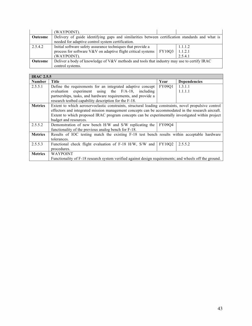
(WAYPOINT). Outcome Delivery of guide identifying gaps and similarities between certification standards and what is
needed for adaptive control system certification. 2.5.4.2 Initial software safety assurance techniques that provide a
process for software V&V on adaptive flight critical systems (WAYPOINT).
FY10Q3 1.1.1.2 1.1.2.1 2.5.4.1
Outcome Deliver a body of knowledge of V&V methods and tools that industry may use to certify IRAC control systems.
IRAC 2.5.5 Number Title Year Dependencies 2.5.5.1 Define the requirements for an integrated adaptive concept
evaluation experiment using the F/A-18, including partnerships, tasks, and hardware requirements, and provide a research testbed capability description for the F-18.
FY09Q1 1.3.1.1 1.1.1.1
Metrics Extent to which aeroservoelastic constraints, structural loading constraints, novel propulsive control effectors and integrated mission management concepts can be accommodated in the research aircraft. Extent to which proposed IRAC program concepts can be experimentally investigated within project budget and resources.
2.5.5.2 Demonstration of new bench H/W and S/W replicating the functionality of the previous analog bench for F-18.
FY09Q4
Metrics Results of IOC testing match the existing F-18 test bench results within acceptable hardware tolerances.
2.5.5.3 Functional check flight evaluation of F-18 H/W, S/W and procedures.
FY10Q2 2.5.5.2
Metrics WAYPOINT Functionality of F-18 research system verified against design requirements; and wheels off the ground.
43
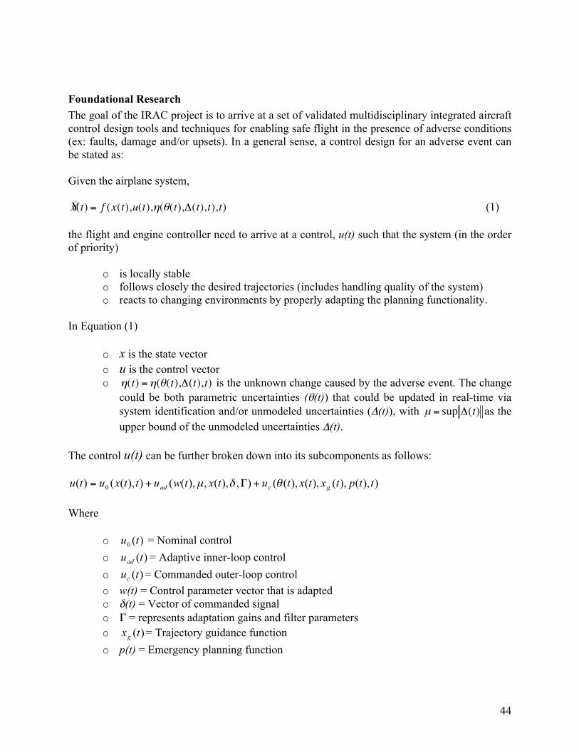
Foundational Research The goal of the IRAC project is to arrive at a set of validated multidisciplinary integrated aircraft control design tools and techniques for enabling safe flight in the presence of adverse conditions (ex: faults, damage and/or upsets). In a general sense, a control design for an adverse event can be stated as:
Given the airplane system,
(1)
the flight and engine controller need to arrive at a control, u(t) such that the system (in the order of priority)
o is locally stable o follows closely the desired trajectories (includes handling quality of the system) o reacts to changing environments by properly adapting the planning functionality.
In Equation (1)
o x is the state vector o u is the control vector o is the unknown change caused by the adverse event. The change
could be both parametric uncertainties (θ(t)) that could be updated in real-time via system identification and/or unmodeled uncertainties (Δ(t)), with as the upper bound of the unmodeled uncertainties Δ(t).
The control u(t) can be further broken down into its subcomponents as follows:
Where
o = Nominal control o = Adaptive inner-loop control o = Commanded outer-loop control o w(t) = Control parameter vector that is adapted o δ(t) = Vector of commanded signal o Γ = represents adaptation gains and filter parameters o = Trajectory guidance function o p(t) = Emergency planning function
44
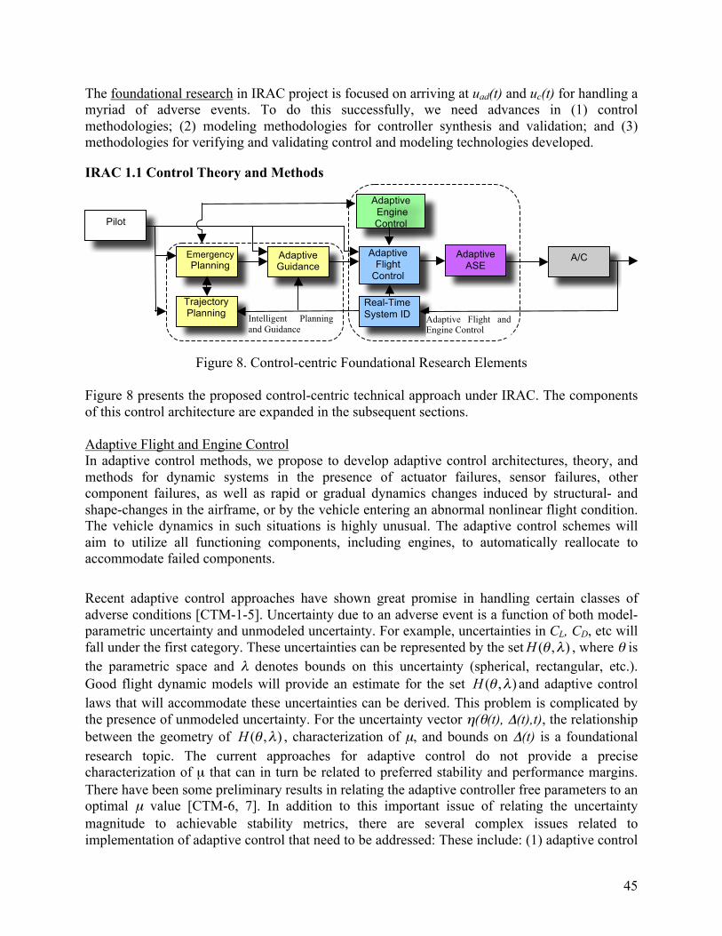
ugmentat on
The foundational research in IRAC project is focused on arriving at uad(t) and uc(t) for handling a myriad of adverse events. To do this successfully, we need advances in (1) control methodologies; (2) modeling methodologies for controller synthesis and validation; and (3) methodologies for verifying and validating control and modeling technologies developed.
IRAC 1.1 Control Theory and Methods
A/C Adaptive Flight
Control
Adaptive Guidance
Real-Time System ID
Emergency Planning
Pilot
Trajectory Planning
Adaptive ASE
A i
Intelligent Planning and Guidance
Adaptive Flight and Engine Control
Adaptive Engine Control
Figure 8. Control-centric Foundational Research Elements
Figure 8 presents the proposed control-centric technical approach under IRAC. The components of this control architecture are expanded in the subsequent sections.
Adaptive Flight and Engine Control In adaptive control methods, we propose to develop adaptive control architectures, theory, and methods for dynamic systems in the presence of actuator failures, sensor failures, other component failures, as well as rapid or gradual dynamics changes induced by structural- and shape-changes in the airframe, or by the vehicle entering an abnormal nonlinear flight condition. The vehicle dynamics in such situations is highly unusual. The adaptive control schemes will aim to utilize all functioning components, including engines, to automatically reallocate to accommodate failed components.
Recent adaptive control approaches have shown great promise in handling certain classes of adverse conditions [CTM-1-5]. Uncertainty due to an adverse event is a function of both model-parametric uncertainty and unmodeled uncertainty. For example, uncertainties in CL, CD, etc will fall under the first category. These uncertainties can be represented by the set , where θ is the parametric space and λ denotes bounds on this uncertainty (spherical, rectangular, etc.). Good flight dynamic models will provide an estimate for the set and adaptive control laws that will accommodate these uncertainties can be derived. This problem is complicated by the presence of unmodeled uncertainty. For the uncertainty vector η(θ(t), Δ(t),t), the relationship between the geometry of , characterization of µ, and bounds on Δ(t) is a foundational research topic. The current approaches for adaptive control do not provide a precise characterization of µ that can in turn be related to preferred stability and performance margins. There have been some preliminary results in relating the adaptive controller free parameters to an optimal µ value [CTM-6, 7]. In addition to this important issue of relating the uncertainty magnitude to achievable stability metrics, there are several complex issues related to implementation of adaptive control that need to be addressed: These include: (1) adaptive control
45
in the presence of static and dynamic saturation; (2) cross-coupling between longitudinal and lateral axes due to failures, damage, and varying time constants for adaptation; (3) on-line reconfiguration, especially achieving attitude control using propulsive forces and moments; and (4) adaptive control theory that can effectively address inherently nonlinear systems as well as effectively the issues of time-scale separation which is important for systems with different time latency such as engines.
Another challenge is to arrive at suitable metrics for stability and performance for both modeled and unmodeled uncertainties. The research will require concepts from linear and nonlinear systems theory, Lyapunov methods, robust control theory, and possibly neural nets and fuzzy systems theory. The performance measures will be useful in evaluating and comparing adaptive controllers and adaptive control approaches. The goal is to arrive at stability and controllability margins equivalent to currently available margins for linear concepts. In addition, research into applicability of existing handling qualities metrics will be evaluated for its potential use in damage-adaptive control research.
In order to develop high performance adaptive controllers with guaranteed stability and performance for handling a variety of adverse events during the entire flight envelope, it is extremely important for the control architecture to be diverse and encompass a variety of designs and analyses. We plan to examine a variety of adaptive control approaches including but not limited to: (a) direct adaptive control for handling abrupt system changes; (b) indirect adaptive control for slow varying uncertainties; (c) reinforcement learning control for outer-loop guidance function adaptations; and (d) adaptive predictive control for handling multi-rate actuators.
Intelligent Guidance and Planning Intelligent guidance and planning focuses on generating xg(t) and p(t) in real-time such that safe landing can be achieved via pilot-in-the-loop control. Some of the tools to assist pilots in safely landing a damaged aircraft include: (1) automated planning techniques that can assist pilots in generating, evaluating, and choosing a flight path to an emergency landing site; (2) trajectory planning algorithms that can accommodate off-nominal constraints placed on aircraft maneuverability and control; (3) a guidance system architecture that can work with (inner-loop) adaptive controllers to provide (outer-loop) autopilot control and flight director guidance under off-nominal conditions; and (4) dynamic flight and maneuvering envelope constraint determination methods that can determine flight envelope and maneuvering constraints under off-nominal conditions.
There has been considerable research on automated planning techniques in AI, but much of this work has been limited to problems that are largely discrete in nature – i.e. where there are few continuous variables involved, or where such choices can be discretized. These techniques are probably amenable to the choice of airport and runway, given information about maneuvering constraints and environmental conditions. However, finding a viable and safe route to the final approach course is more closely related to problems such as 3D robotic path planning, so combining these two types of planning techniques will likely be necessary. To tackle these problems, we envision a constraint-based search throughout the space of landing sites/runways that are reachable and obey hard constraints associated with aircraft capability. For each such possible landing site/runway, we could then perform a search for a coarse spatial path to a final approach fix, taking into account weather and terrain obstacles, and aircraft descent and turning
46
capabilities. This path can then be used as input to the more detailed trajectory planning algorithms to evaluate path feasibility. Once a feasible plan is found, we could then evaluate the robustness of the plan with respect to aircraft capabilities and the possibilities of further degradation in capabilities or weather conditions.
There are several challenges in this approach. First, although it should be relatively easy to evaluate the risk or robustness of a specific plan, it is considerably more difficult to focus the search on finding low risk plans in the first place. This will require the development of heuristics that can guide the search for a landing site, runway and path by assessing risk of an abstract plan – one that is not yet worked out completely. A second problem is that of improving the robustness of a generated plan by improving the path, or by considering and planning for the possibility of additional failures or contingencies. This sort of automated contingency planning has been investigated (by team members) for robotic path planning, but the techniques have limitations, and are still embryonic in nature [CTM-8,9]. Fundamental research will be required to extend techniques for planning under uncertainty to deal with the continuous variables in this domain, to focus search on finding robust plans, and to further improve the robustness of plans that have been generated.
The flight plans produced by conventional Flight Management Systems are composed of “waypoints”, and the “legs” connecting these waypoints. These legs incorporate standard turn rates and predicted climb and descent performance in order to define the lateral and vertical trajectories that are used to guide the aircraft, and to meet the airspeed and altitude constraints that can be placed on various waypoints. However, in cases where the aircraft is unable to meet these constraints, it is left to the pilots to resolve the situation. As a result, intelligent trajectory planning algorithms will be used to (a) accommodate additional constraints such as asymmetric bank angle limits, (b) create specialized legs that are capable of bleeding off excess energy to comply with approach and landing constraints under conditions such as in cases where the aircraft is no longer capable of achieving level flight, (c) assess the performance of the aircraft such as changes in lift/drag characteristics, and (d) re-plan when necessary. Furthermore, when constraints are not achievable, the trajectory planner may request a change either in lateral path or in aircraft configuration. For example, when the aircraft has excessive energy a lateral leg can be extended, a stack of spiral leg can be added or drag may be increased, by using a combination of speed breaks, flaps or landing gear. If the aircraft has insufficient energy, some lateral legs can be eliminated (assuming such a change is allowed), therefore resulting in a shorter path and a higher energy at a given waypoint.
The intelligent guidance system architecture will be capable of augmenting (outer-loop) control gains and rate limits in order to work with the adaptive (inner-loop) control system. This will be accomplished by taking advantage of the consistent handling qualities provided by the adaptive control system in terms of natural frequency responses and pitch and roll rate limits. The adaptive guidance system will also incorporate flight envelope and maneuvering constraints, as well as other “soft constraints” which will define the “aggressiveness factor” that corresponds to the current state of the aircraft.
Adaptive Structural Mode Suppression
47
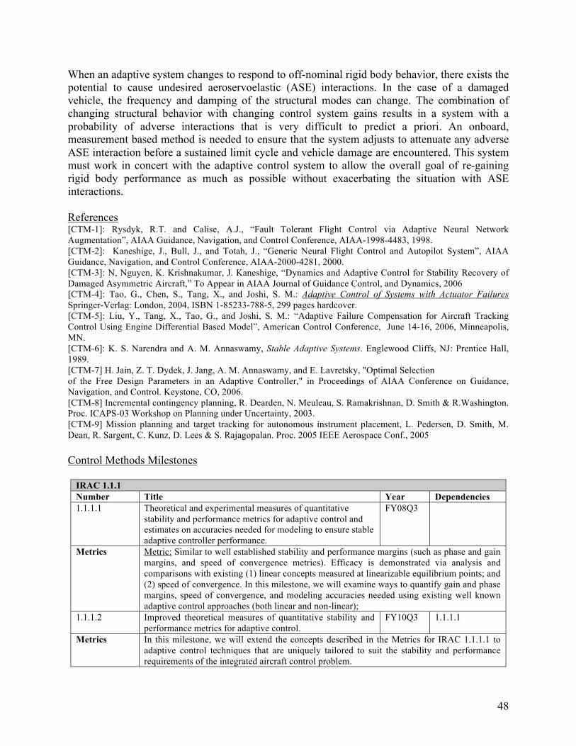
When an adaptive system changes to respond to off-nominal rigid body behavior, there exists the potential to cause undesired aeroservoelastic (ASE) interactions. In the case of a damaged vehicle, the frequency and damping of the structural modes can change. The combination of changing structural behavior with changing control system gains results in a system with a probability of adverse interactions that is very difficult to predict a priori. An onboard, measurement based method is needed to ensure that the system adjusts to attenuate any adverse ASE interaction before a sustained limit cycle and vehicle damage are encountered. This system must work in concert with the adaptive control system to allow the overall goal of re-gaining rigid body performance as much as possible without exacerbating the situation with ASE interactions.
References [CTM-1]: Rysdyk, R.T. and Calise, A.J., “Fault Tolerant Flight Control via Adaptive Neural Network Augmentation”, AIAA Guidance, Navigation, and Control Conference, AIAA-1998-4483, 1998. [CTM-2]: Kaneshige, J., Bull, J., and Totah, J., “Generic Neural Flight Control and Autopilot System”, AIAA Guidance, Navigation, and Control Conference, AIAA-2000-4281, 2000. [CTM-3]: N, Nguyen, K. Krishnakumar, J. Kaneshige, “Dynamics and Adaptive Control for Stability Recovery of Damaged Asymmetric Aircraft,” To Appear in AIAA Journal of Guidance Control, and Dynamics, 2006 [CTM-4]: Tao, G., Chen, S., Tang, X., and Joshi, S. M.: Adaptive Control of Systems with Actuator Failures Springer-Verlag: London, 2004, ISBN 1-85233-788-5, 299 pages hardcover. [CTM-5]: Liu, Y., Tang, X., Tao, G., and Joshi, S. M.: “Adaptive Failure Compensation for Aircraft Tracking Control Using Engine Differential Based Model”, American Control Conference, June 14-16, 2006, Minneapolis, MN. [CTM-6]: K. S. Narendra and A. M. Annaswamy, Stable Adaptive Systems. Englewood Cliffs, NJ: Prentice Hall, 1989. [CTM-7] H. Jain, Z. T. Dydek, J. Jang, A. M. Annaswamy, and E. Lavretsky, "Optimal Selection of the Free Design Parameters in an Adaptive Controller," in Proceedings of AIAA Conference on Guidance, Navigation, and Control. Keystone, CO, 2006. [CTM-8] Incremental contingency planning, R. Dearden, N. Meuleau, S. Ramakrishnan, D. Smith & R.Washington. Proc. ICAPS-03 Workshop on Planning under Uncertainty, 2003. [CTM-9] Mission planning and target tracking for autonomous instrument placement, L. Pedersen, D. Smith, M. Dean, R. Sargent, C. Kunz, D. Lees & S. Rajagopalan. Proc. 2005 IEEE Aerospace Conf., 2005
Control Methods Milestones
IRAC 1.1.1 Number Title Year Dependencies 1.1.1.1 Theoretical and experimental measures of quantitative
stability and performance metrics for adaptive control and estimates on accuracies needed for modeling to ensure stable adaptive controller performance.
FY08Q3
Metrics Metric: Similar to well established stability and performance margins (such as phase and gain margins, and speed of convergence metrics). Efficacy is demonstrated via analysis and comparisons with existing (1) linear concepts measured at linearizable equilibrium points; and (2) speed of convergence. In this milestone, we will examine ways to quantify gain and phase margins, speed of convergence, and modeling accuracies needed using existing well known adaptive control approaches (both linear and non-linear);
1.1.1.2 Improved theoretical measures of quantitative stability and performance metrics for adaptive control.
FY10Q3 1.1.1.1
Metrics In this milestone, we will extend the concepts described in the Metrics for IRAC 1.1.1.1 to adaptive control techniques that are uniquely tailored to suit the stability and performance requirements of the integrated aircraft control problem.
48
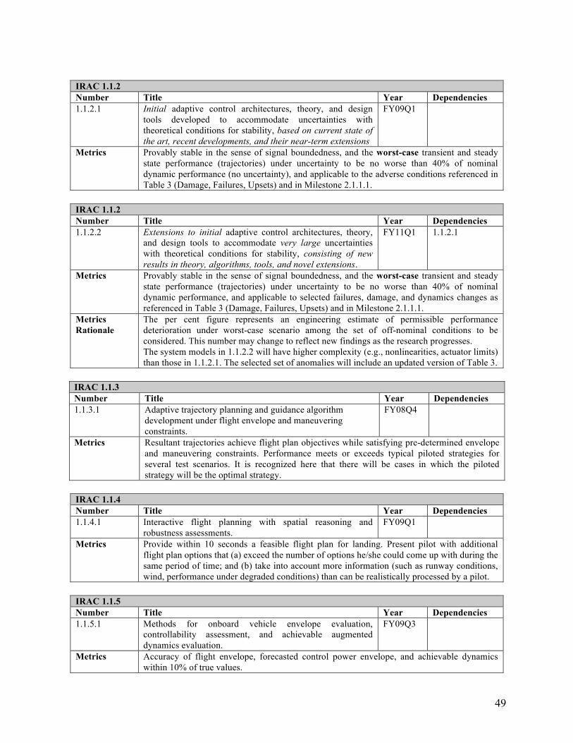
IRAC 1.1.2 Number Title Year Dependencies 1.1.2.1 Initial adaptive control architectures, theory, and design
tools developed to accommodate uncertainties with theoretical conditions for stability, based on current state of the art, recent developments, and their near-term extensions
FY09Q1
Metrics Provably stable in the sense of signal boundedness, and the worst-case transient and steady state performance (trajectories) under uncertainty to be no worse than 40% of nominal dynamic performance (no uncertainty), and applicable to the adverse conditions referenced in Table 3 (Damage, Failures, Upsets) and in Milestone 2.1.1.1.
IRAC 1.1.2 Number Title Year Dependencies 1.1.2.2 Extensions to initial adaptive control architectures, theory,
and design tools to accommodate very large uncertainties with theoretical conditions for stability, consisting of new results in theory, algorithms, tools, and novel extensions.
FY11Q1 1.1.2.1
Metrics Provably stable in the sense of signal boundedness, and the worst-case transient and steady state performance (trajectories) under uncertainty to be no worse than 40% of nominal dynamic performance, and applicable to selected failures, damage, and dynamics changes as referenced in Table 3 (Damage, Failures, Upsets) and in Milestone 2.1.1.1.
Metrics Rationale
The per cent figure represents an engineering estimate of permissible performance deterioration under worst-case scenario among the set of off-nominal conditions to be considered. This number may change to reflect new findings as the research progresses. The system models in 1.1.2.2 will have higher complexity (e.g., nonlinearities, actuator limits) than those in 1.1.2.1. The selected set of anomalies will include an updated version of Table 3.
IRAC 1.1.3 Number Title Year Dependencies 1.1.3.1 Adaptive trajectory planning and guidance algorithm
development under flight envelope and maneuvering constraints.
FY08Q4
Metrics Resultant trajectories achieve flight plan objectives while satisfying pre-determined envelope and maneuvering constraints. Performance meets or exceeds typical piloted strategies for several test scenarios. It is recognized here that there will be cases in which the piloted strategy will be the optimal strategy.
IRAC 1.1.4 Number Title Year Dependencies 1.1.4.1 Interactive flight planning with spatial reasoning and
robustness assessments. FY09Q1
Metrics Provide within 10 seconds a feasible flight plan for landing. Present pilot with additional flight plan options that (a) exceed the number of options he/she could come up with during the same period of time; and (b) take into account more information (such as runway conditions, wind, performance under degraded conditions) than can be realistically processed by a pilot.
IRAC 1.1.5 Number Title Year Dependencies 1.1.5.1 Methods for onboard vehicle envelope evaluation,
controllability assessment, and achievable augmented dynamics evaluation.
FY09Q3
Metrics Accuracy of flight envelope, forecasted control power envelope, and achievable dynamics within 10% of true values.
49
Metrics The accuracy in determining the overall maneuvering envelope limits will directly affect the Rationale margins of safety that the intelligent flight planning system must accommodate. Our goal is to
achieve an accuracy of within 10% in order to prevent planning that is overly restricted in
Number
terms of determining the desired flight envelope.
Title Year Dependencies 1.1.6.1 Apply conformant and contingency planning methods to FY10Q1
accommodate possible variations in the flight/maneuvering envelope, schedule aircraft configuration changes, and compute alternate trajectories in an attempt to increase the likelihood of a safe landing.
Metrics Resultant flight plans will achieve emergency planning objectives while accommodating 68.27% (1 sigma) of variations in envelope and maneuvering constraints, and produce alternate flight plans for variations up to 99.73% (3 sigma) when feasible. Performance meets or exceeds typical piloted strategies for several test scenarios. It is recognized here that there will be cases in which the piloted strategy will be the optimal strategy.
IRAC 1.1.6
IRAC 1.2 Modeling Methods For IRAC modeling, the research is focused on arriving at physics-based models of the effects of damages/failures and upsets in terms of the forces and moments acting on the aircraft. These forces and moments can be largely classified under (a) inertial effects [MM-6], (b) non-linear, unsteady aerodynamic effects, (c) structural effects, (d) propulsive effects, and (e) aeroservoelastic effects. Since the project focus is on control design, our interest is in producing flight dynamic models that can be used to synthesize adaptive control laws and to validate their performance in simulation. Model-based validation (as opposed to flight test validation) of control laws will require some limited wind tunnel and flight test validation of these simulation models. This project will take advantage of previous modeling work done in the NASA Aviation Safety and Security Program. Development of advanced models will require a project trade off between higher fidelity and cost.
In an adverse event, some lifting surfaces may experience separated flows or damage resulting in changes in the lift distribution and/or changes in the mass and inertia characteristics. This may cause significant and abrupt changes in the flight characteristics. Furthermore, changes in stability and control derivatives associated with non-linear and time-dependent changes in aerodynamic characteristics can render the aircraft unstable. Consequently, these effects can lead to a non-equilibrium flight that can adversely affect the ability for a flight control system to maintain the aircraft stability. In other instances, a reduced structural rigidity of a damaged airframe may manifest in elastic motions that can interfere with a flight control system, and potentially can result in excessive structural loading on critical lifting surfaces. Thus, in a highly dynamic, off-nominal flight environment with many sources of uncertainty due to adverse events, a flight control system must be able to cope with complex and uncertain aircraft dynamics.
Aerodynamic Modeling for Adverse Conditions Flight regimes outside the design envelope may involve separated flows, vortical flows, and other aerodynamic phenomena that from a mathematical modeling perspective are classified as nonlinear unsteady aerodynamics. One of the technical challenges under IRAC is in arriving at
50
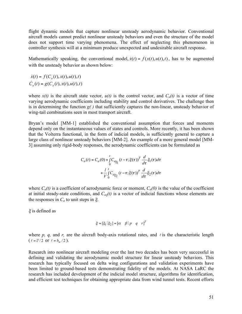
flight dynamic models that capture nonlinear unsteady aerodynamic behavior. Conventional aircraft models cannot predict nonlinear unsteady behaviors and even the structure of the model does not support time varying phenomena. The effect of neglecting this phenomenon in controller synthesis will at a minimum produce unexpected and undesirable aircraft response.
Mathematically speaking, the conventional model, , has to be augmented with the unsteady behavior as shown below:
where x(t) is the aircraft state vector, u(t) is the control vector, and Ca(t) is a vector of time varying aerodynamic coefficients including stability and control derivatives. The challenge then is in determining the function g( ) that sufficiently captures the non-linear, unsteady behavior of wing-tail combinations seen in most transport aircraft.
Bryan’s model [MM-1] established the conventional assumption that forces and moments depend only on the instantaneous values of states and controls. More recently, it has been shown that the Volterra functional, in the form of indicial models, is sufficiently general to capture a large class of nonlinear unsteady behaviors [MM-2]. An example of a more general model [MM-3] assuming only rigid-body responses, the aerodynamic coefficients can be formulated as
where Ca(t) is a coefficient of aerodynamic force or moment, Ca(0) is the value of the coefficient at initial steady-state conditions, and Caξ(t) is a vector of indicial functions whose elements are the responses in Ca to unit steps in ξ.
ξ is defined as
where p, q, and r, are the aircraft body-axis rotational rates, and is the characteristic length ( or ).
Research into nonlinear aircraft modeling over the last two decades has been very successful in defining and validating the aerodynamic model structure for linear unsteady behaviors. This research has typically focused on delta wing configurations and validation experiments have been limited to ground-based tests demonstrating fidelity of the models. At NASA LaRC the research has included development of the indicial model structure, algorithms for identification, and efficient test techniques for obtaining appropriate data from wind tunnel tests. Recent efforts
51
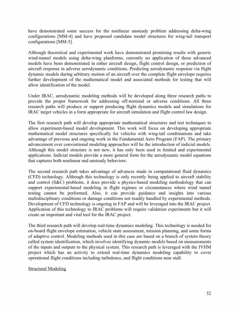
have demonstrated some success for the nonlinear unsteady problem addressing delta-wing configurations [MM-4] and have proposed candidate model structures for wing-tail transport configurations [MM-5].
Although theoretical and experimental work have demonstrated promising results with generic wind-tunnel models using delta-wing planforms, currently no application of these advanced models have been demonstrated in either aircraft design, flight control design, or prediction of aircraft response in adverse aerodynamic conditions. Predicting aerodynamic response via flight dynamic models during arbitrary motion of an aircraft over the complete flight envelope requires further development of the mathematical model and associated methods for testing that will allow identification of the model.
Under IRAC, aerodynamic modeling methods will be developed along three research paths to provide the proper framework for addressing off-nominal or adverse conditions. All three research paths will produce or support producing flight dynamics models and simulations for IRAC target vehicles in a form appropriate for aircraft simulation and flight control law design.
The first research path will develop appropriate mathematical structures and test techniques to allow experiment-based model development. This work will focus on developing appropriate mathematical model structures specifically for vehicles with wing-tail combinations and take advantage of previous and ongoing work in the Fundamental Aero Program (FAP). The primary advancement over conventional modeling approaches will be the introduction of indicial models. Although this model structure is not new, it has only been used in limited and experimental applications. Indicial models provide a more general form for the aerodynamic model equations that captures both nonlinear and unsteady behaviors.
The second research path takes advantage of advances made in computational fluid dynamics (CFD) technology. Although this technology is only recently being applied to aircraft stability and control (S&C) problems, it does provide a physics-based modeling methodology that can support experimental-based modeling in flight regimes or circumstances where wind tunnel testing cannot be performed. Also, it can provide guidance and insights into various multidisciplinary conditions or damage conditions not readily handled by experimental methods. Development of CFD technology is ongoing in FAP and will be leveraged into the IRAC project. Application of this technology to IRAC problems will require validation experiments but it will create an important and vital tool for the IRAC project.
The third research path will develop real-time dynamics modeling. This technology is needed for on-board flight envelope estimation, vehicle state assessment, mission planning, and some forms of adaptive control. Modeling methods used in this case are based on a branch of system theory called system identification, which involves identifying dynamic models based on measurements of the inputs and outputs to the physical system. This research path is leveraged with the IVHM project which has an activity to extend real-time dynamics modeling capability to cover operational flight conditions including turbulence, and flight conditions near stall.
Structural Modeling
52
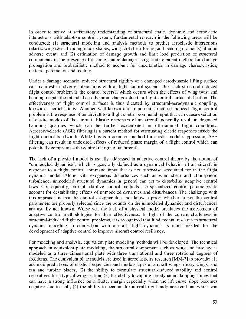
In order to arrive at satisfactory understanding of structural static, dynamic and aeroelastic interactions with adaptive control system, fundamental research in the following areas will be conducted: (1) structural modeling and analysis methods to predict aeroelastic interactions (elastic wing twist, bending mode shapes, wing root shear forces, and bending moments) after an adverse event; and (2) estimation of damage growth and limit load prediction of structural components in the presence of discrete source damage using finite element method for damage propagation and probabilistic method to account for uncertainties in damage characteristics, material parameters and loading.
Under a damage scenario, reduced structural rigidity of a damaged aerodynamic lifting surface can manifest in adverse interactions with a flight control system. One such structural-induced flight control problem is the control reversal which occurs when the effects of wing twist and bending negate the intended aerodynamic changes due to a flight control surface deflection. The effectiveness of flight control surfaces is thus dictated by structural-aerodynamic coupling, known as aeroelasticity. Another well-known and important structural-induced flight control problem is the response of an aircraft to a flight control command input that can cause excitation of elastic modes of the aircraft. Elastic responses of an aircraft generally result in degraded handling qualities which can be further exacerbated in off-nominal flight conditions. Aeroservoelastic (ASE) filtering is a current method for attenuating elastic responses inside the flight control bandwidth. While this is a common method for elastic modal suppression, ASE filtering can result in undesired effects of reduced phase margin of a flight control which can potentially compromise the control margin of an aircraft.
The lack of a physical model is usually addressed in adaptive control theory by the notion of “unmodeled dynamics”, which is generally defined as a dynamical behavior of an aircraft in response to a flight control command input that is not otherwise accounted for in the flight dynamic model. Along with exogenous disturbances such as wind shear and atmospheric turbulence, unmodeled structural dynamics in general can act to destabilize adaptive control laws. Consequently, current adaptive control methods use specialized control parameters to account for destabilizing effects of unmodeled dynamics and disturbances. The challenge with this approach is that the control designer does not know a priori whether or not the control parameters are properly selected since the bounds on the unmodeled dynamics and disturbances are usually not known. Worse yet, the lack of a physical model precludes the assessment of adaptive control methodologies for their effectiveness. In light of the current challenges in structural-induced flight control problems, it is recognized that fundamental research in structural dynamic modeling in connection with aircraft flight dynamics is much needed for the development of adaptive control to improve aircraft control resiliency.
For modeling and analysis, equivalent plate modeling methods will be developed. The technical approach in equivalent plate modeling, the structural component such as wing and fuselage is modeled as a three-dimensional plate with three translational and three rotational degrees of freedoms. The equivalent plate models are used in aeroelasticity research [MM-7] to provide: (1) accurate predictions of elastic frequencies and mode shapes of aircraft wings, rotary wings, and fan and turbine blades, (2) the ability to formulate structural-induced stability and control derivatives for a typical wing section, (3) the ability to capture aerodynamic damping forces that can have a strong influence on a flutter margin especially when the lift curve slope becomes negative due to stall, (4) the ability to account for aircraft rigid-body accelerations which can
53
excite elastic modes and generate structural loads, (5) the ability to integrate with rigid-body flight dynamics to yield a new state-space formulation for adaptive control research, and (6) a rapid modeling capability.
The equivalent plate modeling also provides an effective way to model discrete source damage, to assess aeroelastic effect of damage on internal load distribution, frequency response and flutter boundary changes. In equivalent plate modeling, finite element method combined with an optimization technique will be used to match the stiffness and mass distribution of the original structure [MM-8].
Assessment and characterization of damage involves estimation of damage growth and limit load prediction of structural components in the presence of discrete source damage using diagnosis and prognosis methods. In diagnosis methods, damage assessment and characterization are performed at the current state of damage, while in prognosis methods it is performed for a future control induced damaged state based on the current diagnosed state. Estimation of control induced damage growth and limit load prediction are achieved using finite element based methods. Inverse Methods use the strain or deformation measured at optimized locations by minimizing the number of sensors needed to predict a given damage size and location. The inverse methods will adopt the research performed under IVHM 1.2.5 and 1.2.7 milestones.
Prognostics methods for estimating damage growth and limit load prediction of structural components requires high fidelity computational methods. This new capability will permit calculation of allowable flight loads that are crucial for correctly adapting flight and engine control systems to minimize structural overload. The damage assessment and propagation techniques developed under IVHM Milestone 1.2.6 based on Extended Finite Element Method (X-FEM) will be used calculate the structural limit loads due to control induced damage growth. Also computational methods developed from previous programs, including the NASA Aircraft Structural Integrity Program (ASIP) will be leveraged. In the near term, the results from the high fidelity prognostics methods will be integrated in simple response surface based methods to use in rapid modeling for prediction. The tools will be developed to include damage in the wing, tail, and control surfaces.
Propulsive Modeling and Simulation The primary focus of integrated flight-propulsion control is to effectively use the engines as control effectors for achieving desired aircraft stability and response characteristics under adverse conditions. To realize this, foundational research is needed both in quantifying the stability and maneuverability benefits of integrated flight-propulsion control and in identifying potential engine enhancements for achieving these benefits.
For enhanced stability and maneuverability using engines as active control effectors, the engine thrust response characteristics have to be optimally shaped. The related research questions are: (1) what are the desired thrust response characteristics for adverse conditions of focus (as stated in Table 3); and (2) how to effectively control the engine variables such as margins, limits, efficiencies, and fan speeds, to achieve the required thrust response characteristics. The first research question will also reveal the instances for which the engines have to be operated beyond their normal operational envelope and will help in quantifying this need.
54
A study is planned to be conducted early in the project for examining the engine response characteristics needed to counter various adverse conditions. This study will be conducted using existing simplified flight dynamic models to enable first order estimates of the engine response characteristics needed. With a good initial estimates of engine characteristics defined for integrated flight and propulsion control, the plan is to examine engine control strategies using a an engine simulation model developed for this study. Once a good modeling capability for integrated effects is established, higher order estimates of the engine characteristics can be studied. This study is referenced in Milestone 2.2.2.1.
The engine modeling effort will first focus on providing the current flight simulators with a realistic engine performance model of sufficient fidelity for this level of research. This task includes a detailed simulation of engine controller settings and corresponding engine performance using the currently available engine models and test data. A flight test data collection effort will provide important engine performance characteristics to calibrate the engine operation beyond the typical sea level static (SLS) test data provided by engine companies. Once validated with this flight-test data, this simulation will be used to develop a generic version that will be made available to the IRAC community.
To model engine operation beyond the normal operational envelope, the engine controller’s safety logic might have to be violated. Because the engines were designed to a standard operating profile, the logic restricts internal rotational speeds and temperatures to achieve a specified safe life limit. However, under adverse conditions, engine life may need to be traded for increased responsiveness as requested by the integrated flight and propulsion controller. Acceleration schedules can be shortened and temperature limits can be increased to achieve the engine performance required to ‘save’ the aircraft. This research will explore various ways of achieving the desired engine response characteristics while maintaining critical engine parameters such as stall margins. It is understood that there is technical risk in modeling for enhanced operation and in validating the model for operation in regions of the flight envelope that are beyond normal use (see section 3.2). Our intention is to clearly identify the potential of enhanced engine operation and to provide guidelines for the next-generation engine design and operation.
To minimize risk to the vehicle and passengers after an adverse condition, the engine life must also be quantified. Toward this end, a probabilistic engine “life meter” will be developed that is able to track the life consumed and return a probability of failure based on current usage and future intended operation. This information will be used by the integrated flight-propulsion controller to enable a trade-off between engine life and safety of the overall airplane. This approach enables bursts of potentially life-saving performance while maintaining a reasonable safety margin selected by the integrated flight-propulsion controller according to the level of urgency of the encountered adverse condition. One of the main challenges in this research is to model the impact on engine part life and the impact on safety caused by the relaxation of the controller limits and other controller actions to increase engine performance.
References: [MM-1] Byran, G. H.: Stability in Aviation, MacMillan and Co., London, 1911.
55
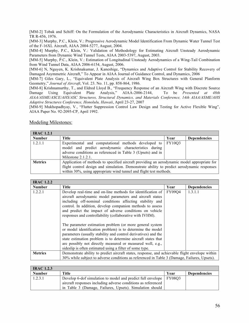
[MM-2] Tobak and Schiff: On the Formulation of the Aerodynamic Characteristics in Aircraft Dynamics, NASA TR R-456, 1976. [MM-3] Murphy, P.C., Klein, V.: Progressive Aerodynamic Model Identification From Dynamic Water Tunnel Test of the F-16XL Aircraft, AIAA 2004-5277, August, 2004. [MM-4] Murphy, P.C., Klein, V.: Validation of Methodology for Estimating Aircraft Unsteady Aerodynamic Parameters from Dynamic Wind Tunnel Tests, AIAA 2003-5397, August, 2003. [MM-5] Murphy, P.C., Klein, V.: Estimation of Longitudinal Unsteady Aerodynamics of a Wing-Tail Combination from Wind Tunnel Data, AIAA 2006-6154, August, 2006. [MM-6] N, Nguyen, K. Krishnakumar, J. Kaneshige, “Dynamics and Adaptive Control for Stability Recovery of Damaged Asymmetric Aircraft,” To Appear in AIAA Journal of Guidance Control, and Dynamics, 2006 [MM-7] Giles Gary, L., “Equivalent Plate Analysis of Aircraft Wing Box Structures with General Planform Geometry,” Journal of Aircraft, Vol. 23. No. 11, pp. 858-864, 1986. [MM-8] Krishnamurthy, T., and Eldred Lloyd B., “Frequency Response of an Aircraft Wing with Discrete Source Damage Using Equivalent Plate Analysis,” AIAA-2006-2144, To be Presented at 48th AIAA/ASME/ASCE/AHS/ASC Structures, Structural Dynamics, and Materials Conference, 14th AIAA/ASME/AHS Adaptive Structures Conference, Honolulu, Hawaii, April 23-27, 2007 [MM-9] Mukhopadhyay, V., “Flutter Suppression Control Law Design and Testing for Active Flexible Wing”, AIAA Paper No. 92-2095-CP, April 1992.
Modeling Milestones:
IRAC 1.2.1 Number Title Year Dependencies 1.2.1.1 Experimental and computational methods developed to
model and predict aerodynamic characteristics during adverse conditions as referenced in Table 3 (Upsets) and in Milestone 2.1.2.1.
FY10Q3
Metrics Application of methods to specified aircraft providing an aerodynamic model appropriate for flight control design and simulation. Demonstrate ability to predict aerodynamic responses within 30%, using appropriate wind tunnel and flight test methods.
IRAC 1.2.2 Number Title Year Dependencies 1.2.2.1 Develop real-time and on-line methods for identification of
aircraft aerodynamic model parameters and aircraft states including off-nominal conditions affecting stability and control. In addition, develop companion methods to assess and predict the impact of adverse conditions on vehicle responses and controllability (collaborative with IVHM).
The parameter estimation problem (or more general system or model identification problem) is to determine the model parameters (usually stability and control derivatives) and the state estimation problem is to determine aircraft states that are possibly not directly measured or measured well, e.g., sideslip is often estimated using a filter of some type.
FY09Q4 1.3.1.1
Metrics Demonstrate ability to predict aircraft states, response, and achievable flight envelope within 30% while subject to adverse conditions as referenced in Table 3 (Damage, Failures, Upsets).
IRAC 1.2.3 Number Title Year Dependencies 1.2.3.1 Develop 6-dof simulation to model and predict full envelope
aircraft responses including adverse conditions as referenced in Table 3 (Damage, Failures, Upsets). Simulation should
FY08Q3
56
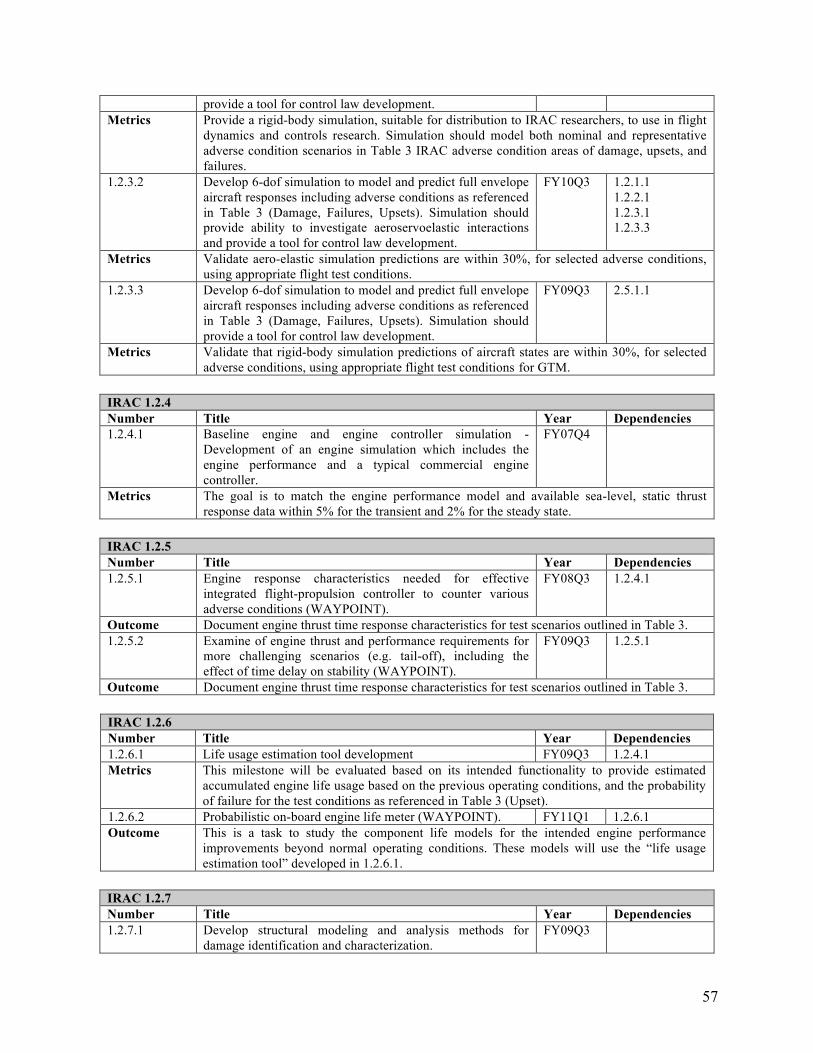
provide a tool for control law development. Metrics Provide a rigid-body simulation, suitable for distribution to IRAC researchers, to use in flight
dynamics and controls research. Simulation should model both nominal and representative adverse condition scenarios in Table 3 IRAC adverse condition areas of damage, upsets, and failures.
1.2.3.2 Develop 6-dof simulation to model and predict full envelope aircraft responses including adverse conditions as referenced in Table 3 (Damage, Failures, Upsets). Simulation should provide ability to investigate aeroservoelastic interactions and provide a tool for control law development.
FY10Q3 1.2.1.1 1.2.2.1 1.2.3.1 1.2.3.3
Metrics Validate aero-elastic simulation predictions are within 30%, for selected adverse conditions, using appropriate flight test conditions.
1.2.3.3 Develop 6-dof simulation to model and predict full envelope aircraft responses including adverse conditions as referenced in Table 3 (Damage, Failures, Upsets). Simulation should provide a tool for control law development.
FY09Q3 2.5.1.1
Metrics Validate that rigid-body simulation predictions of aircraft states are within 30%, for selected adverse conditions, using appropriate flight test conditions for GTM.
IRAC 1.2.4 Number Title Year Dependencies 1.2.4.1 Baseline engine and engine controller simulation -
Development of an engine simulation which includes the engine performance and a typical commercial engine controller.
FY07Q4
Metrics The goal is to match the engine performance model and available sea-level, static thrust response data within 5% for the transient and 2% for the steady state.
IRAC 1.2.5 Number Title Year Dependencies 1.2.5.1 Engine response characteristics needed for effective
integrated flight-propulsion controller to counter various adverse conditions (WAYPOINT).
FY08Q3 1.2.4.1
Outcome Document engine thrust time response characteristics for test scenarios outlined in Table 3. 1.2.5.2 Examine of engine thrust and performance requirements for
more challenging scenarios (e.g. tail-off), including the effect of time delay on stability (WAYPOINT).
FY09Q3 1.2.5.1
Outcome Document engine thrust time response characteristics for test scenarios outlined in Table 3.
IRAC 1.2.6 Number Title Year Dependencies 1.2.6.1 Life usage estimation tool development FY09Q3 1.2.4.1 Metrics This milestone will be evaluated based on its intended functionality to provide estimated
accumulated engine life usage based on the previous operating conditions, and the probability of failure for the test conditions as referenced in Table 3 (Upset).
1.2.6.2 Probabilistic on-board engine life meter (WAYPOINT). FY11Q1 1.2.6.1 Outcome This is a task to study the component life models for the intended engine performance
improvements beyond normal operating conditions. These models will use the “life usage estimation tool” developed in 1.2.6.1.
IRAC 1.2.7 Number Title Year Dependencies 1.2.7.1 Develop structural modeling and analysis methods for
damage identification and characterization. FY09Q3
57
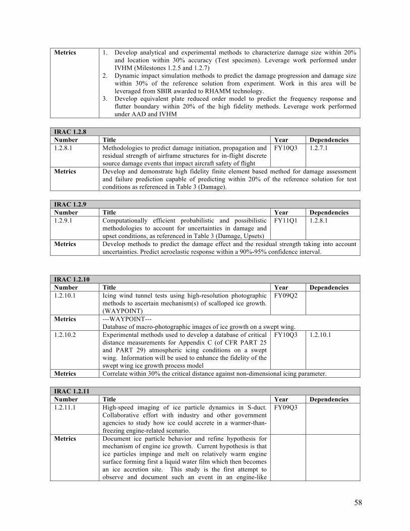
Metrics 1. Develop analytical and experimental methods to characterize damage size within 20% and location within 30% accuracy (Test specimen). Leverage work performed under IVHM (Milestones 1.2.5 and 1.2.7)
2. Dynamic impact simulation methods to predict the damage progression and damage size within 30% of the reference solution from experiment. Work in this area will be leveraged from SBIR awarded to RHAMM technology.
3. Develop equivalent plate reduced order model to predict the frequency response and flutter boundary within 20% of the high fidelity methods. Leverage work performed under AAD and IVHM
IRAC 1.2.8 Number Title Year Dependencies 1.2.8.1 Methodologies to predict damage initiation, propagation and
residual strength of airframe structures for in-flight discrete source damage events that impact aircraft safety of flight
FY10Q3 1.2.7.1
Metrics Develop and demonstrate high fidelity finite element based method for damage assessment and failure prediction capable of predicting within 20% of the reference solution for test conditions as referenced in Table 3 (Damage).
IRAC 1.2.9 Number Title Year Dependencies 1.2.9.1 Computationally efficient probabilistic and possibilistic
methodologies to account for uncertainties in damage and upset conditions, as referenced in Table 3 (Damage, Upsets)
FY11Q1 1.2.8.1
Metrics Develop methods to predict the damage effect and the residual strength taking into account uncertainties. Predict aeroelastic response within a 90%-95% confidence interval.
IRAC 1.2.10 Number Title Year Dependencies 1.2.10.1 Icing wind tunnel tests using high-resolution photographic
methods to ascertain mechanism(s) of scalloped ice growth. (WAYPOINT)
FY09Q2
Metrics ---WAYPOINT---Database of macro-photographic images of ice growth on a swept wing.
1.2.10.2 Experimental methods used to develop a database of critical distance measurements for Appendix C (of CFR PART 25 and PART 29) atmospheric icing conditions on a swept wing. Information will be used to enhance the fidelity of the swept wing ice growth process model
FY10Q3 1.2.10.1
Metrics Correlate within 30% the critical distance against non-dimensional icing parameter.
IRAC 1.2.11 Number Title Year Dependencies 1.2.11.1 High-speed imaging of ice particle dynamics in S-duct.
Collaborative effort with industry and other government agencies to study how ice could accrete in a warmer-than-freezing engine-related scenario.
FY09Q3
Metrics Document ice particle behavior and refine hypothesis for mechanism of engine ice growth. Current hypothesis is that ice particles impinge and melt on relatively warm engine surface forming first a liquid water film which then becomes an ice accretion site. This study is the first attempt to observe and document such an event in an engine-like
58
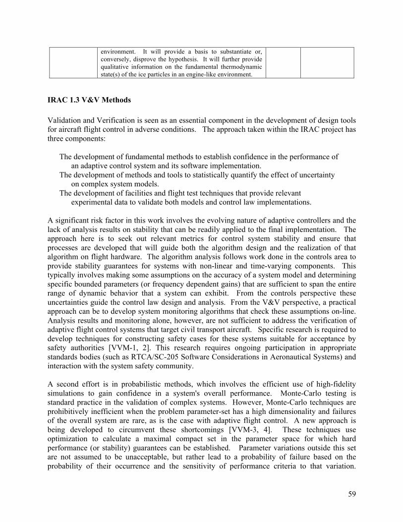
environment. It will provide a basis to substantiate or, conversely, disprove the hypothesis. It will further provide qualitative information on the fundamental thermodynamic state(s) of the ice particles in an engine-like environment.
IRAC 1.3 V&V Methods
Validation and Verification is seen as an essential component in the development of design tools for aircraft flight control in adverse conditions. The approach taken within the IRAC project has three components:
The development of fundamental methods to establish confidence in the performance of an adaptive control system and its software implementation.
The development of methods and tools to statistically quantify the effect of uncertainty on complex system models.
The development of facilities and flight test techniques that provide relevant experimental data to validate both models and control law implementations.
A significant risk factor in this work involves the evolving nature of adaptive controllers and the lack of analysis results on stability that can be readily applied to the final implementation. The approach here is to seek out relevant metrics for control system stability and ensure that processes are developed that will guide both the algorithm design and the realization of that algorithm on flight hardware. The algorithm analysis follows work done in the controls area to provide stability guarantees for systems with non-linear and time-varying components. This typically involves making some assumptions on the accuracy of a system model and determining specific bounded parameters (or frequency dependent gains) that are sufficient to span the entire range of dynamic behavior that a system can exhibit. From the controls perspective these uncertainties guide the control law design and analysis. From the V&V perspective, a practical approach can be to develop system monitoring algorithms that check these assumptions on-line. Analysis results and monitoring alone, however, are not sufficient to address the verification of adaptive flight control systems that target civil transport aircraft. Specific research is required to develop techniques for constructing safety cases for these systems suitable for acceptance by safety authorities [VVM-1, 2]. This research requires ongoing participation in appropriate standards bodies (such as RTCA/SC-205 Software Considerations in Aeronautical Systems) and interaction with the system safety community.
A second effort is in probabilistic methods, which involves the efficient use of high-fidelity simulations to gain confidence in a system's overall performance. Monte-Carlo testing is standard practice in the validation of complex systems. However, Monte-Carlo techniques are prohibitively inefficient when the problem parameter-set has a high dimensionality and failures of the overall system are rare, as is the case with adaptive flight control. A new approach is being developed to circumvent these shortcomings [VVM-3, 4]. These techniques use optimization to calculate a maximal compact set in the parameter space for which hard performance (or stability) guarantees can be established. Parameter variations outside this set are not assumed to be unacceptable, but rather lead to a probability of failure based on the probability of their occurrence and the sensitivity of performance criteria to that variation.
59
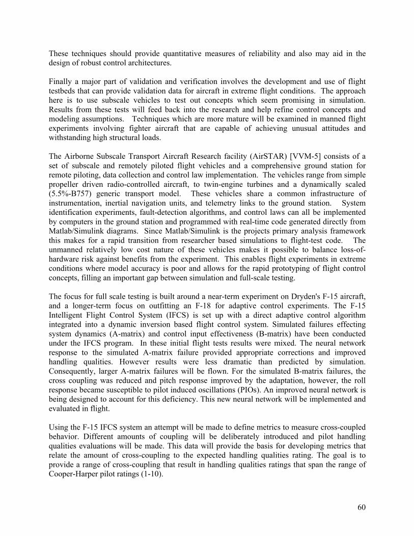
These techniques should provide quantitative measures of reliability and also may aid in the design of robust control architectures.
Finally a major part of validation and verification involves the development and use of flight testbeds that can provide validation data for aircraft in extreme flight conditions. The approach here is to use subscale vehicles to test out concepts which seem promising in simulation. Results from these tests will feed back into the research and help refine control concepts and modeling assumptions. Techniques which are more mature will be examined in manned flight experiments involving fighter aircraft that are capable of achieving unusual attitudes and withstanding high structural loads.
The Airborne Subscale Transport Aircraft Research facility (AirSTAR) [VVM-5] consists of a set of subscale and remotely piloted flight vehicles and a comprehensive ground station for remote piloting, data collection and control law implementation. The vehicles range from simple propeller driven radio-controlled aircraft, to twin-engine turbines and a dynamically scaled (5.5%-B757) generic transport model. These vehicles share a common infrastructure of instrumentation, inertial navigation units, and telemetry links to the ground station. System identification experiments, fault-detection algorithms, and control laws can all be implemented by computers in the ground station and programmed with real-time code generated directly from Matlab/Simulink diagrams. Since Matlab/Simulink is the projects primary analysis framework this makes for a rapid transition from researcher based simulations to flight-test code. The unmanned relatively low cost nature of these vehicles makes it possible to balance loss-of-hardware risk against benefits from the experiment. This enables flight experiments in extreme conditions where model accuracy is poor and allows for the rapid prototyping of flight control concepts, filling an important gap between simulation and full-scale testing.
The focus for full scale testing is built around a near-term experiment on Dryden's F-15 aircraft, and a longer-term focus on outfitting an F-18 for adaptive control experiments. The F-15 Intelligent Flight Control System (IFCS) is set up with a direct adaptive control algorithm integrated into a dynamic inversion based flight control system. Simulated failures effecting system dynamics (A-matrix) and control input effectiveness (B-matrix) have been conducted under the IFCS program. In these initial flight tests results were mixed. The neural network response to the simulated A-matrix failure provided appropriate corrections and improved handling qualities. However results were less dramatic than predicted by simulation. Consequently, larger A-matrix failures will be flown. For the simulated B-matrix failures, the cross coupling was reduced and pitch response improved by the adaptation, however, the roll response became susceptible to pilot induced oscillations (PIOs). An improved neural network is being designed to account for this deficiency. This new neural network will be implemented and evaluated in flight.
Using the F-15 IFCS system an attempt will be made to define metrics to measure cross-coupled behavior. Different amounts of coupling will be deliberately introduced and pilot handling qualities evaluations will be made. This data will provide the basis for developing metrics that relate the amount of cross-coupling to the expected handling qualities rating. The goal is to provide a range of cross-coupling that result in handling qualities ratings that span the range of Cooper-Harper pilot ratings (1-10).
60
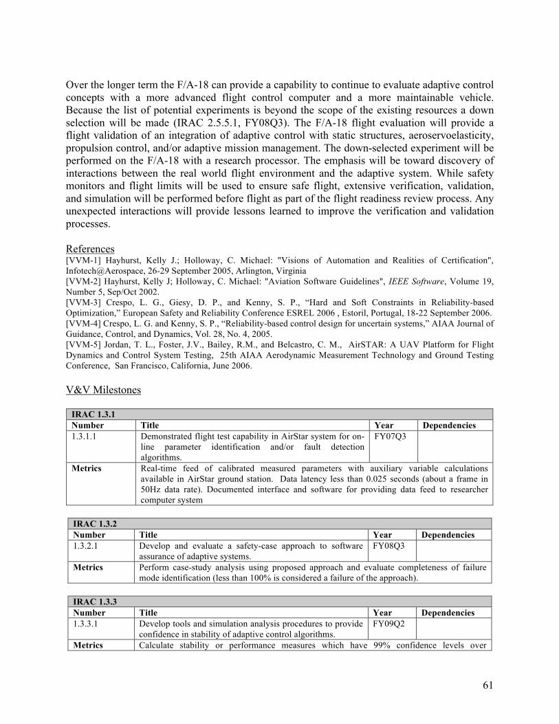
Over the longer term the F/A-18 can provide a capability to continue to evaluate adaptive control concepts with a more advanced flight control computer and a more maintainable vehicle. Because the list of potential experiments is beyond the scope of the existing resources a down selection will be made (IRAC 2.5.5.1, FY08Q3). The F/A-18 flight evaluation will provide a flight validation of an integration of adaptive control with static structures, aeroservoelasticity, propulsion control, and/or adaptive mission management. The down-selected experiment will be performed on the F/A-18 with a research processor. The emphasis will be toward discovery of interactions between the real world flight environment and the adaptive system. While safety monitors and flight limits will be used to ensure safe flight, extensive verification, validation, and simulation will be performed before flight as part of the flight readiness review process. Any unexpected interactions will provide lessons learned to improve the verification and validation processes.
References [VVM-1] Hayhurst, Kelly J.; Holloway, C. Michael: "Visions of Automation and Realities of Certification", Infotech@Aerospace, 26-29 September 2005, Arlington, Virginia [VVM-2] Hayhurst, Kelly J; Holloway, C. Michael: "Aviation Software Guidelines", IEEE Software, Volume 19, Number 5, Sep/Oct 2002. [VVM-3] Crespo, L. G., Giesy, D. P., and Kenny, S. P., “Hard and Soft Constraints in Reliability-based Optimization,” European Safety and Reliability Conference ESREL 2006 , Estoril, Portugal, 18-22 September 2006. [VVM-4] Crespo, L. G. and Kenny, S. P., “Reliability-based control design for uncertain systems,” AIAA Journal of Guidance, Control, and Dynamics, Vol. 28, No. 4, 2005. [VVM-5] Jordan, T. L., Foster, J.V., Bailey, R.M., and Belcastro, C. M., AirSTAR: A UAV Platform for Flight Dynamics and Control System Testing, 25th AIAA Aerodynamic Measurement Technology and Ground Testing Conference, San Francisco, California, June 2006.
V&V Milestones
IRAC 1.3.1 Number Title Year Dependencies 1.3.1.1 Demonstrated flight test capability in AirStar system for on-
line parameter identification and/or fault detection algorithms.
FY07Q3
Metrics Real-time feed of calibrated measured parameters with auxiliary variable calculations available in AirStar ground station. Data latency less than 0.025 seconds (about a frame in 50Hz data rate). Documented interface and software for providing data feed to researcher computer system
IRAC 1.3.2 Number Title Year Dependencies 1.3.2.1 Develop and evaluate a safety-case approach to software
assurance of adaptive systems. FY08Q3
Metrics Perform case-study analysis using proposed approach and evaluate completeness of failure mode identification (less than 100% is considered a failure of the approach).
IRAC 1.3.3 Number Title Year Dependencies 1.3.3.1 Develop tools and simulation analysis procedures to provide
confidence in stability of adaptive control algorithms. FY09Q2
Metrics Calculate stability or performance measures which have 99% confidence levels over
61
prescribed uncertainty space for adaptive algorithms without assumptions on model form or control law structure.
Leveraged Research: Condition/Capability Assessment
In order to adapt the control system for changes in flight or propulsion dynamics due to adverse conditions, it is important to not only be able to assess the current condition of the aircraft and critical subsystems but also to be able to assess what performance the aircraft is capable of achieving in the presence of these adverse conditions. IRAC will leverage the IVHM work on condition assessment to the maximum extent possible and will only perform additional research in this area as needed for IRAC specific goals which are not covered under IVHM. The main focus in IRAC will be to determine the available control authority that the aircraft has based on the current condition so that the goals set for control adaptation are achievable. This effort will also include an integrated assessment of the impact of adaptive control on the condition of the aircraft to ensure that the control actions being taken themselves do not worsen the situation any further. The effort will include the development of methods and tools for determining aircraft performance capability in the form suitable to provide information for control adaptation, and integration of these methods into aircraft simulations for control design.
62