Embed Size (px)
Citation preview

Electric Power Steering Installation in the Pantera
by Gerry Romack &
Alan Cameron

1. Harness with controller 2. Power Wire battery 3. Steering assembly 4. Hall Effect Speed Sensor
Fused Ignition relay & controller assembly that plugs into the sensor computer located on the
steering column.

The Harness plugs into the computer located on the column which has resistance sensors. This allows you
to adjust the amount of assist .

Tape covers the Rheostat Knob before the contoller computer chip.

Speed Control Sensor (designed for the VDO right angle drive)

Early style Dash
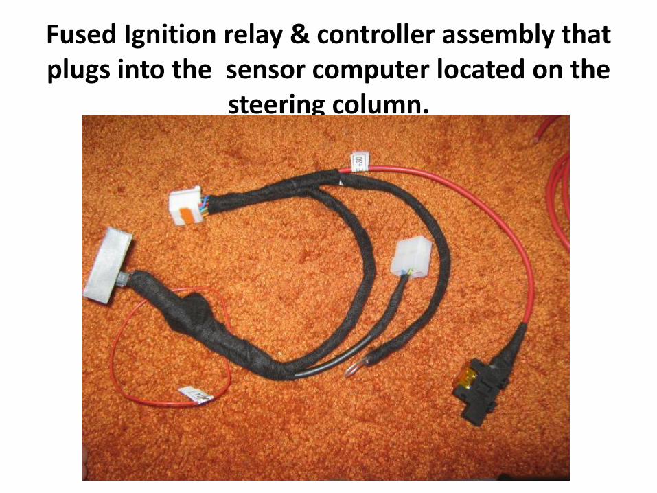
Original Under Dash Mounts

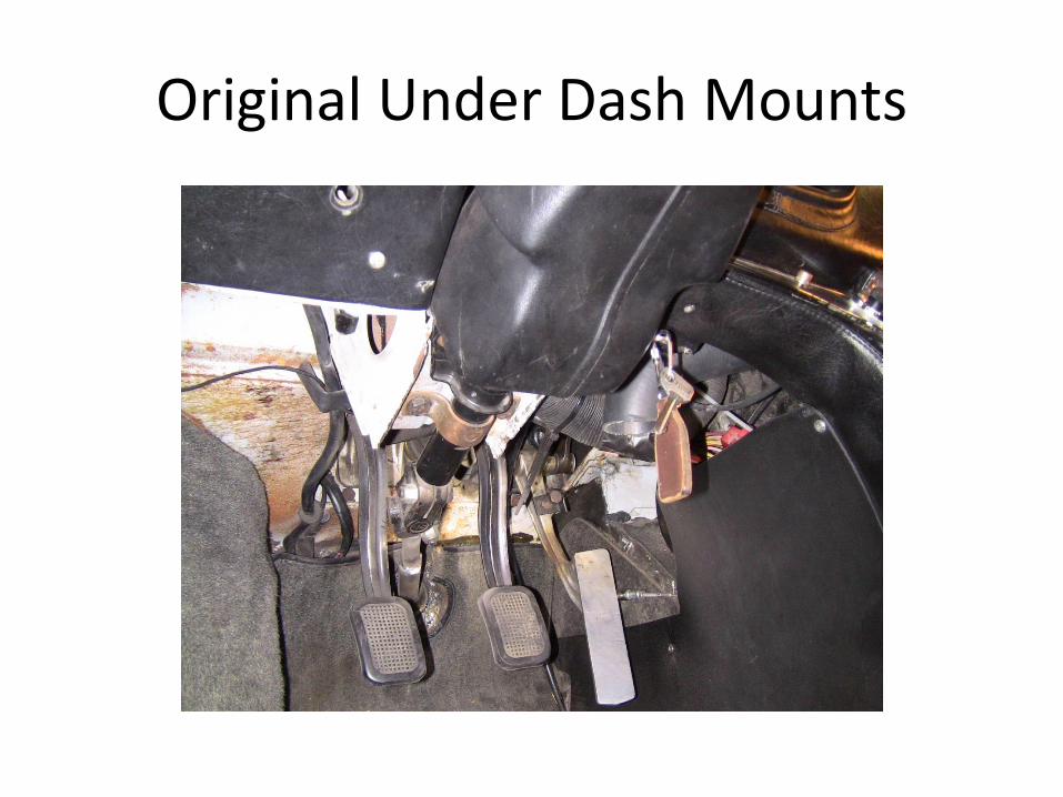
The Steering Wheel is taken off by removing the Allen Headed Bolts.
All parts labeled in a baggy.

Hub Spacer Removed

Owner Removing the 4 bolts holding the Steering Column in place.

Dropping the column with socket set.

Led Work Light make working under the dash much easier.

Side View of the column before removal.
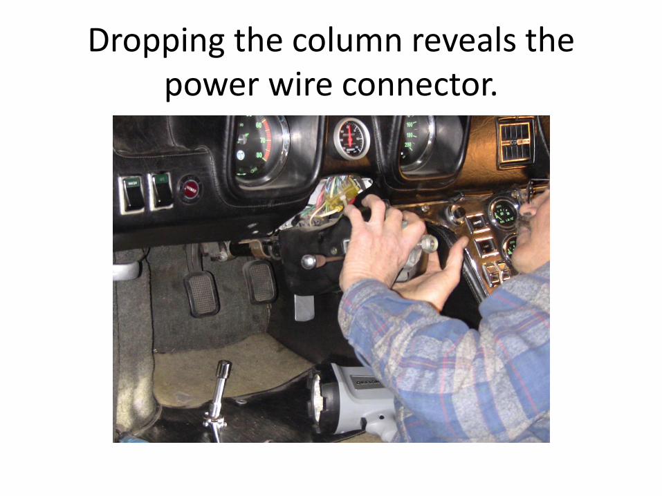
Dropping the column reveals the power wire connector.

Main Power Harness to the Steering Wheel
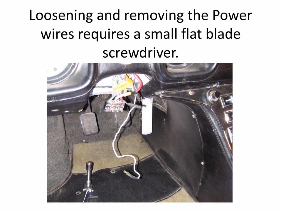
Loosening and removing the Power wires requires a small flat blade
screwdriver.

Electric Assist on the left versus the original Steering Column on the right.
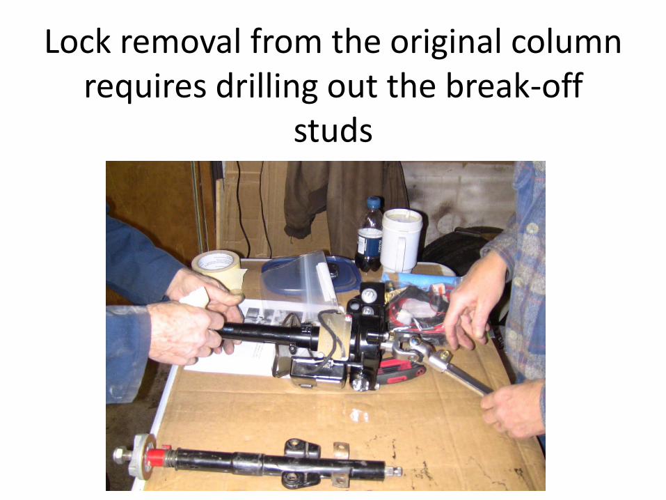
Lock removal from the original column requires drilling out the break-off
studs
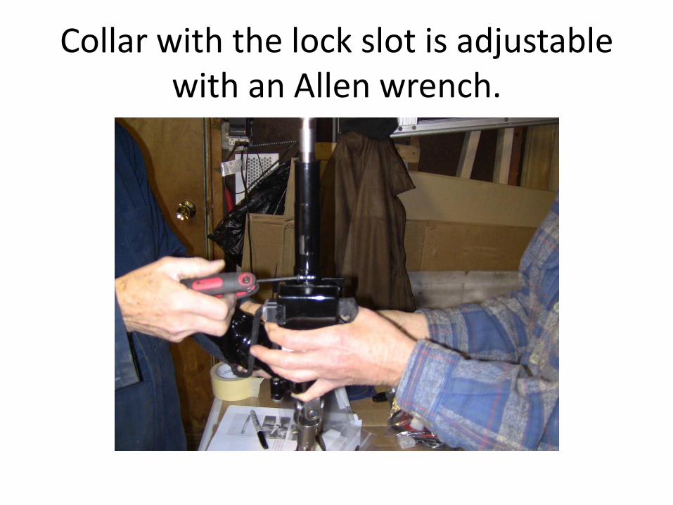
Collar with the lock slot is adjustable with an Allen wrench.
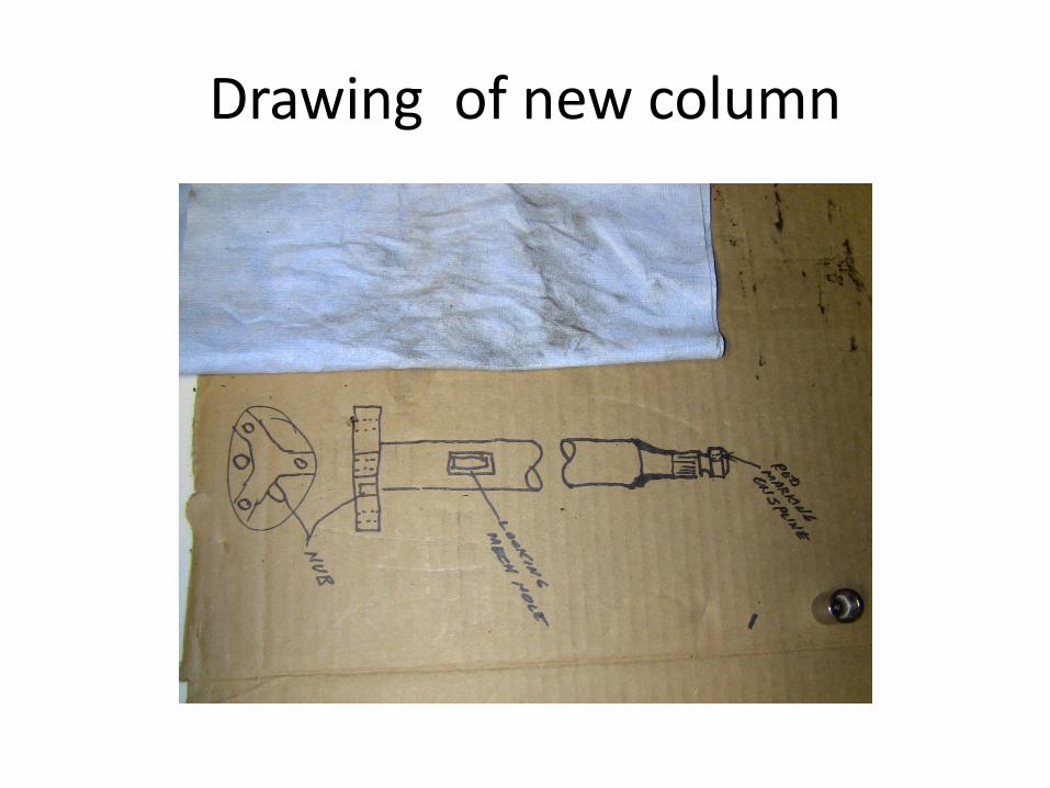
Drawing of new column
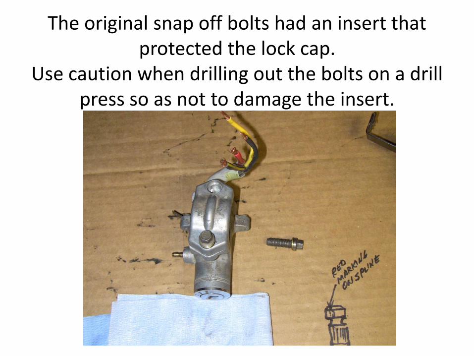
The original snap off bolts had an insert that protected the lock cap.
Use caution when drilling out the bolts on a drill press so as not to damage the insert.

You can see the locking bar here that fits into the slot of the steering shaft.


Slot in the column that the lock fits into.

Lock bolted in place.


Underside of the dash column showing the mounting plate.

First cut

Owner cutting the mounting bracket using a cut off wheel on a Dremel Tool

2nd cutting

Bolt holes are drilled with a right angle Dremel tool (3rd cutting trimmed the sides)

Side view with the air vent hose going through the box.

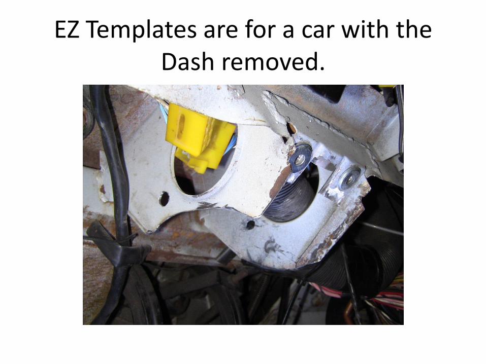
EZ Templates are for a car with the Dash removed.

Trimming the Knuckle on the new unit

The Excess bump is not needed and can be trimmed.
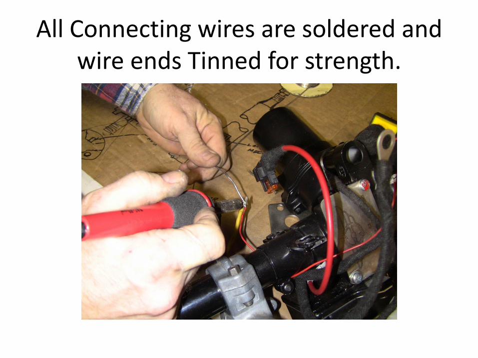
All Connecting wires are soldered and wire ends Tinned for strength.

Wires ready for mounting in the connecting block.

Bracket test fit and Hole adjustment

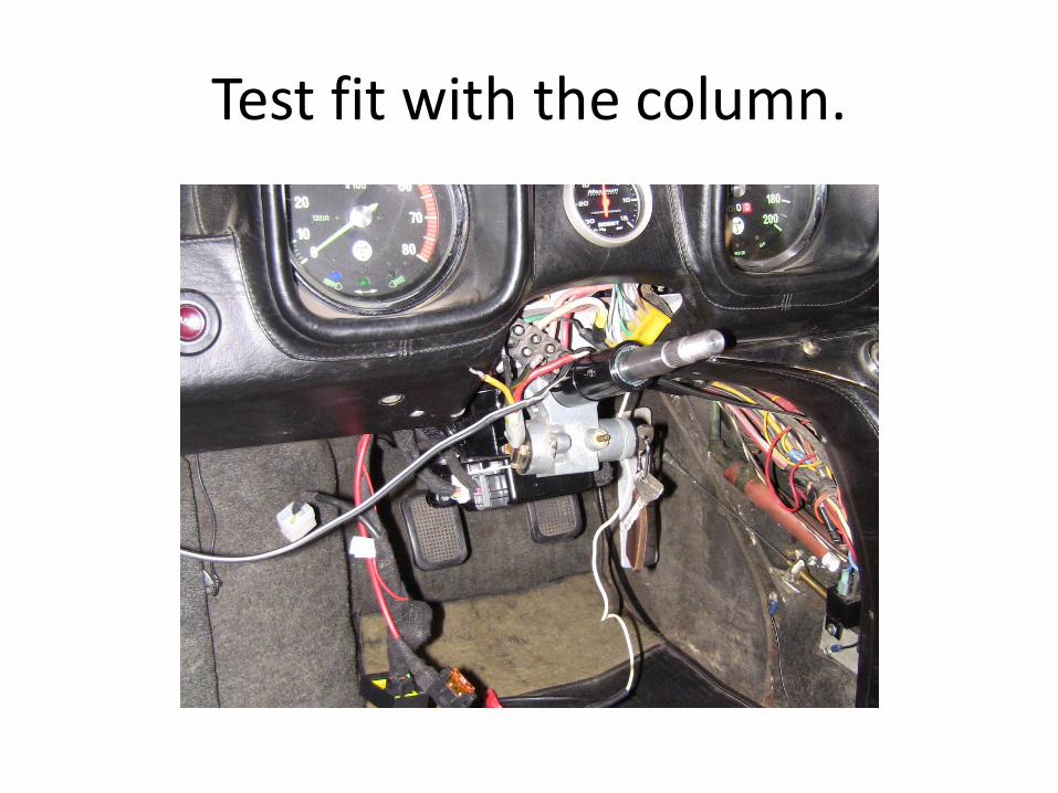
Test fit with the column.

Test fit from the bottom.

ASSEMBLING THE PIECES

Side view
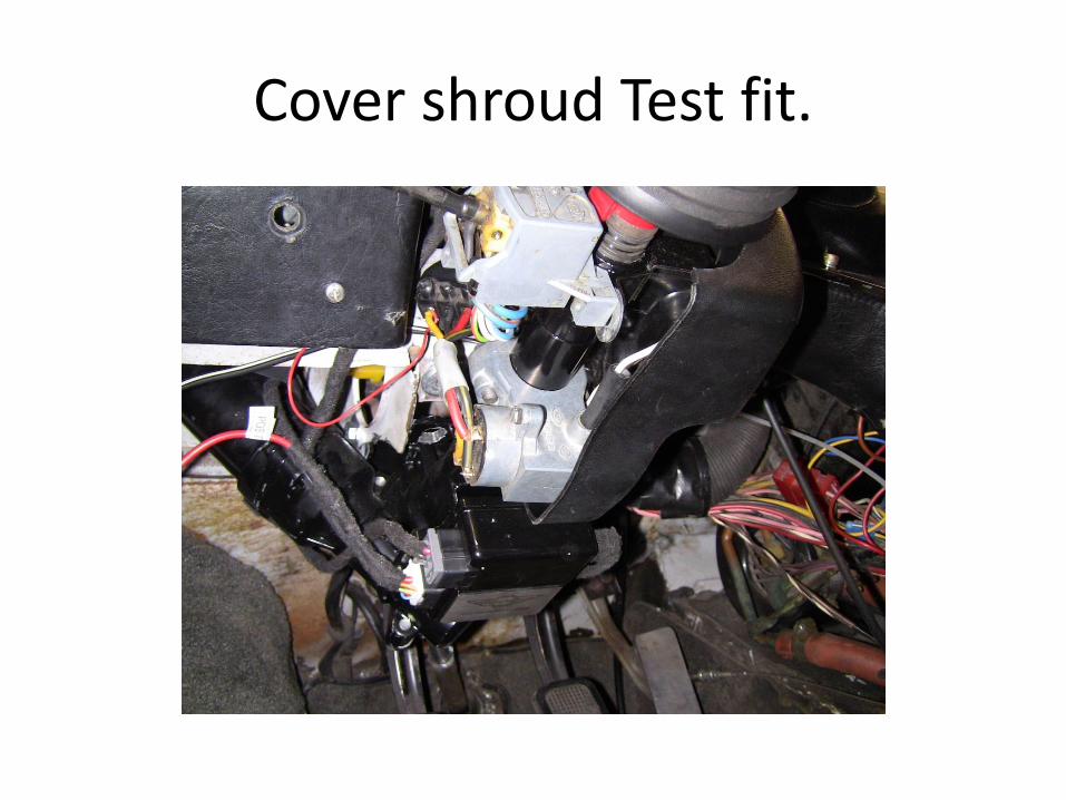
Cover shroud Test fit.

Cover shroud adjustment
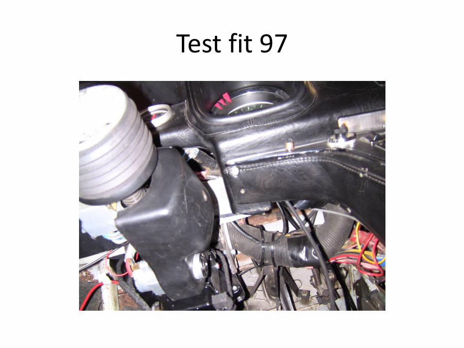
Test fit 97
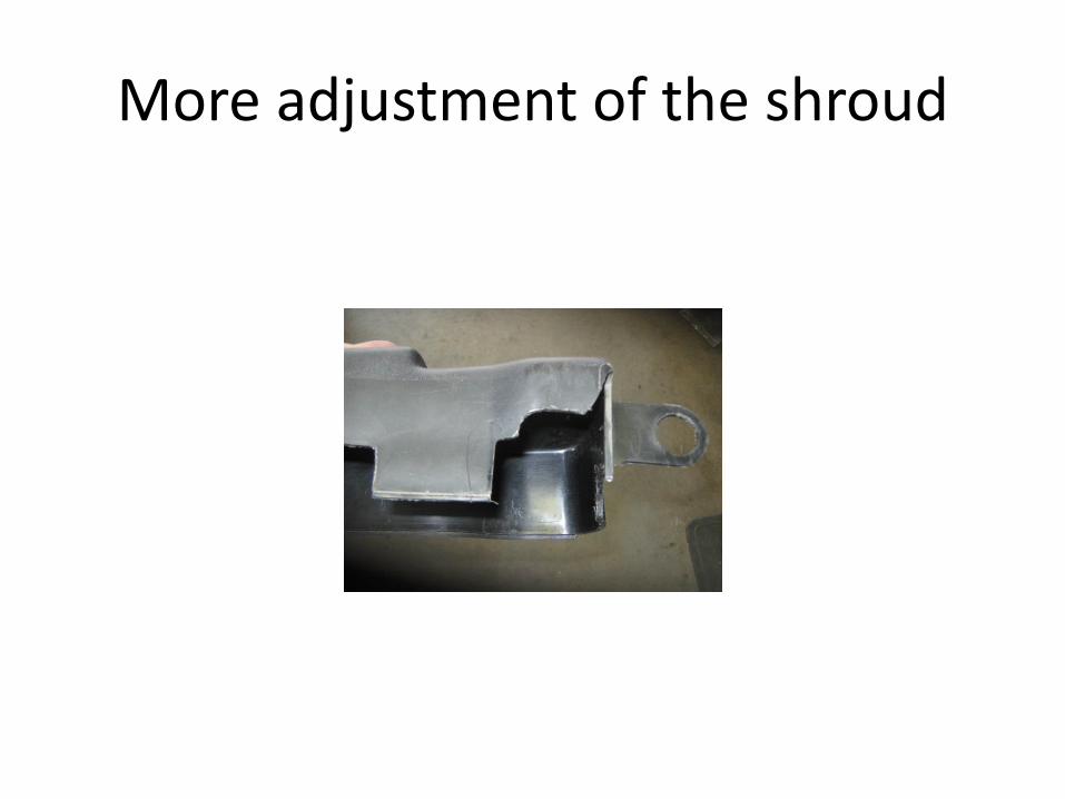
More adjustment of the shroud

Column is slightly larger and requires more plastic trimmed.
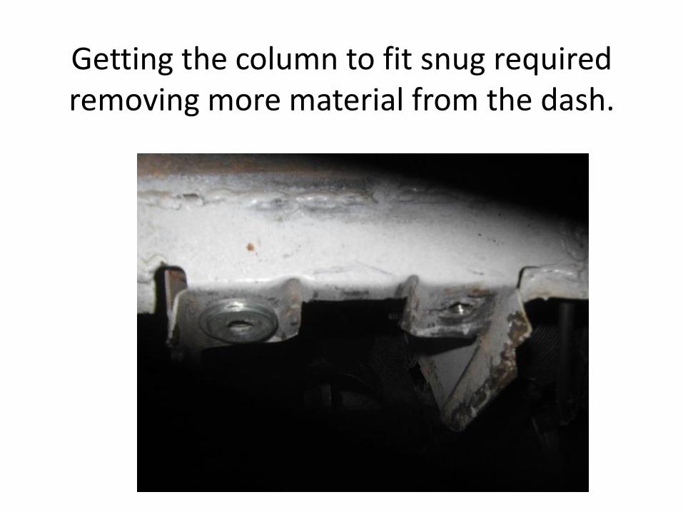
Getting the column to fit snug required removing more material from the dash.

Tab totally removed
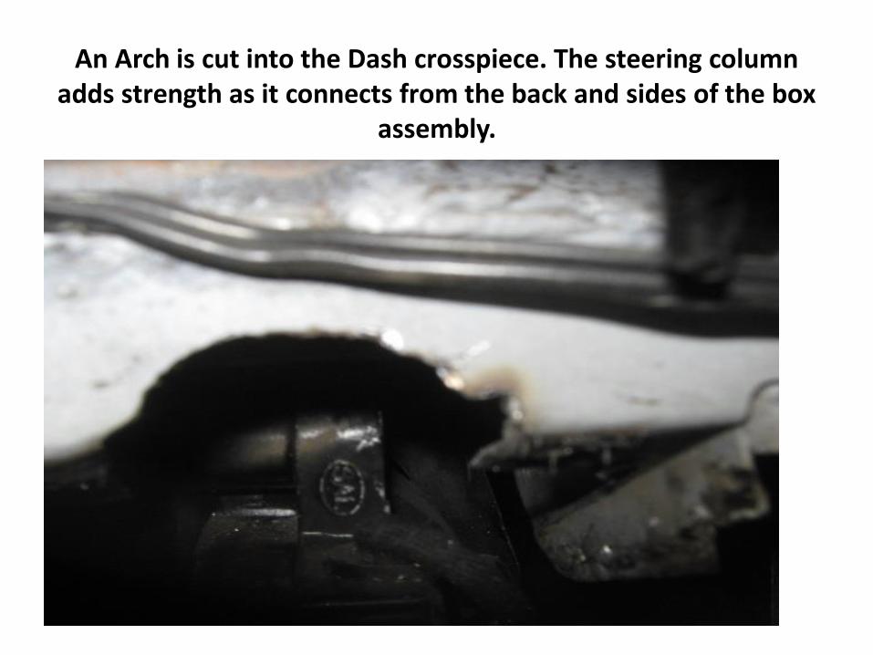
An Arch is cut into the Dash crosspiece. The steering column adds strength as it connects from the back and sides of the box
assembly.

Almost Perfect

Perfect Steering wheel fit after final trimming of the arch.

Pedal Clearance

Speed sensor mounted to the ZF - This sender works with the VDO adapter. If you are considering Converting to the Autometer 200MPH Electric
Speedometer you can use the pulse VST signal and just put a cap on the end. ( No Speedo Cable needed)

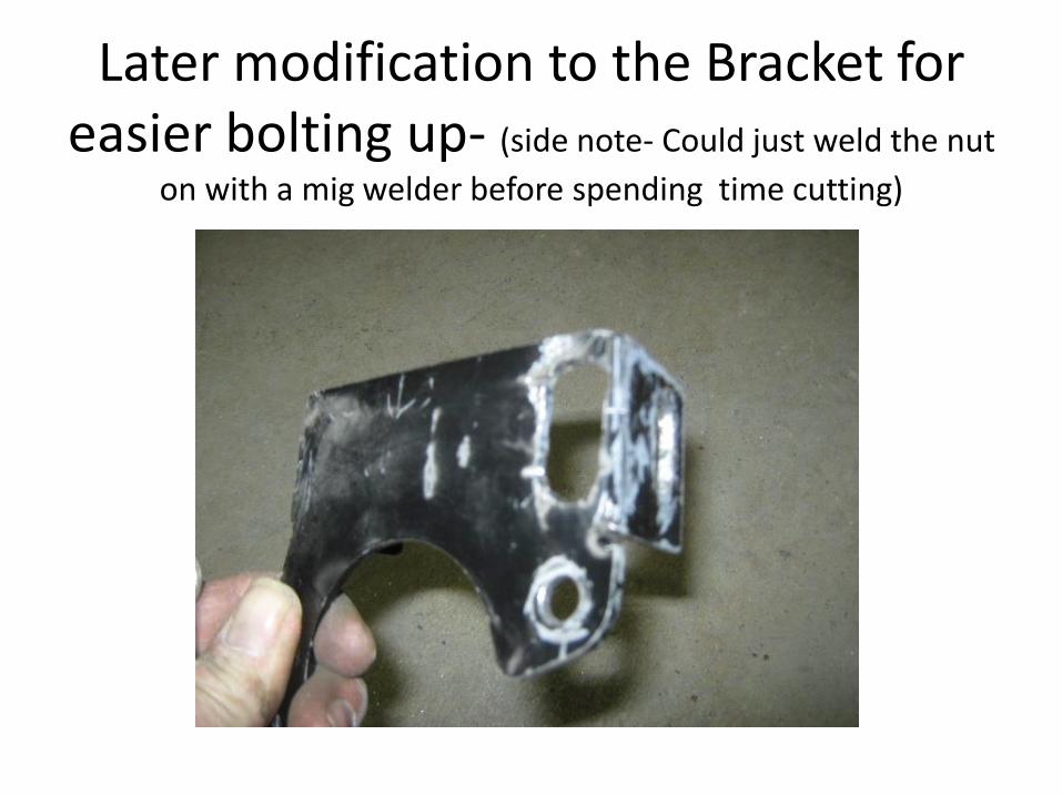
Later modification to the Bracket for easier bolting up- (side note- Could just weld the nut
on with a mig welder before spending time cutting)
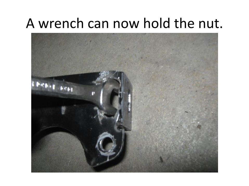
A wrench can now hold the nut.
• Tools needed for Installation
• Socket set…metric.
• Jig saw with Steel cutting blade or Air saw
• A Dremel Tool with right angle adapter-cutting wheels & drill bits.
• Screwdriver - Phillips & Flat Blade
• Soldering iron
• Good LED Light

If you wish to place an order please email me at [email protected] …..We have several people
interested in a group purchase from the Great Lakes
Panteras Club.
• Full details can be accessed by emailing
• And requesting
• Power Steering Assist Information
• Please include your POCA number.