Embed Size (px)
Citation preview
Electric Power Systems and GPS
Alison Silverstein, NASPI Project Manager
Civil GPS Service Interface Committee
September 12, 2016
1
Overview and punchlines
• Power system owners and operators use GPS for navigation, position and timing.
• If we lose GPS today, it will complicate (higher cost, longer duration, lower efficiency), but not kill, grid operations.
• GPS and alternate time sources (and the ways we deliver and use them) need to become more reliable for time-synchronized applications to become mission-critical in the future.
2
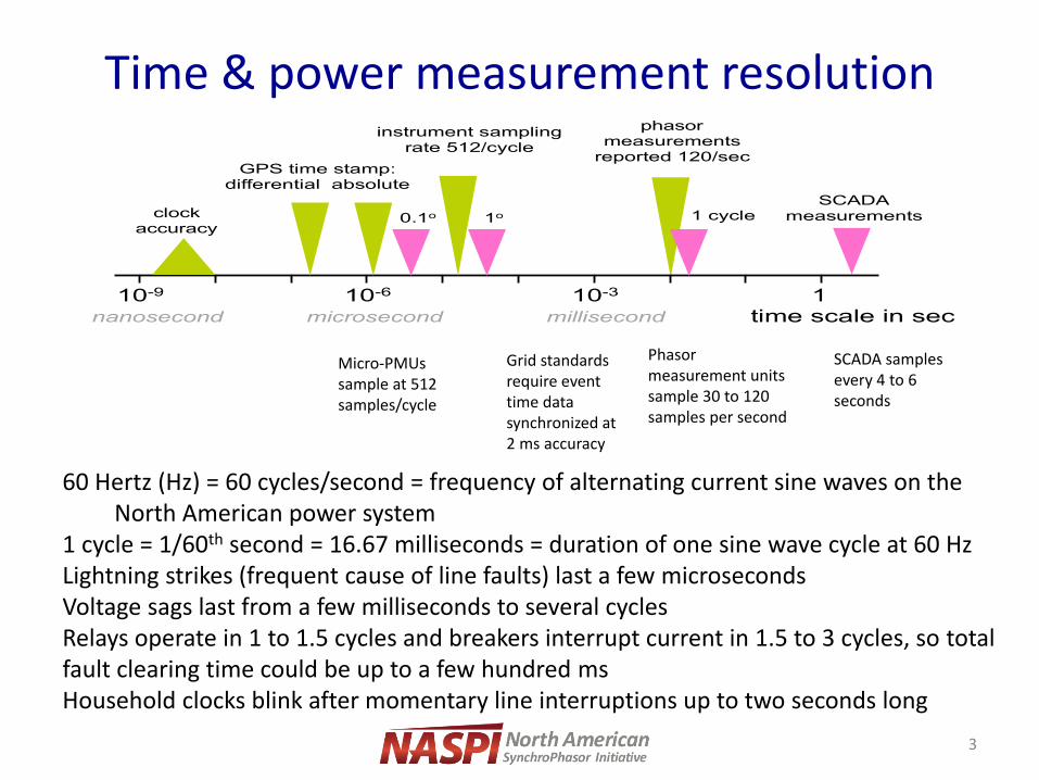
Time & power measurement resolution
3
Phasor measurement units sample 30 to 120 samples per second
SCADA samples every 4 to 6 seconds
60 Hertz (Hz) = 60 cycles/second = frequency of alternating current sine waves on the North American power system 1 cycle = 1/60th second = 16.67 milliseconds = duration of one sine wave cycle at 60 Hz Lightning strikes (frequent cause of line faults) last a few microseconds Voltage sags last from a few milliseconds to several cycles Relays operate in 1 to 1.5 cycles and breakers interrupt current in 1.5 to 3 cycles, so total fault clearing time could be up to a few hundred ms Household clocks blink after momentary line interruptions up to two seconds long
Micro-PMUs sample at 512 samples/cycle
Grid standards require event time data synchronized at 2 ms accuracy
SCADA measurements
10-6 10-3
0.1o 1o 1 cycle
time scale in sec
GPS time stamp: differential absolute
clock accuracy
10-9 1
nanosecond microsecond millisecond
instrument sampling rate 512/cycle
phasor measurements
reported 120/sec
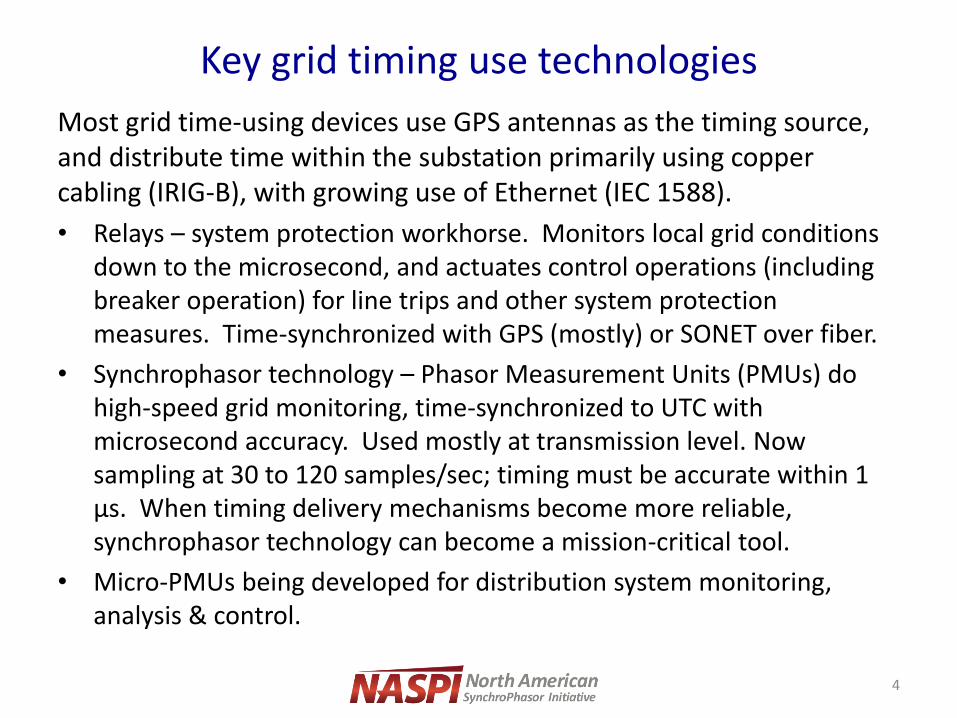
Key grid timing use technologies
Most grid time-using devices use GPS antennas as the timing source, and distribute time within the substation primarily using copper cabling (IRIG-B), with growing use of Ethernet (IEC 1588).
• Relays – system protection workhorse. Monitors local grid conditions down to the microsecond, and actuates control operations (including breaker operation) for line trips and other system protection measures. Time-synchronized with GPS (mostly) or SONET over fiber.
• Synchrophasor technology – Phasor Measurement Units (PMUs) do high-speed grid monitoring, time-synchronized to UTC with microsecond accuracy. Used mostly at transmission level. Now sampling at 30 to 120 samples/sec; timing must be accurate within 1 μs. When timing delivery mechanisms become more reliable, synchrophasor technology can become a mission-critical tool.
• Micro-PMUs being developed for distribution system monitoring, analysis & control.
4
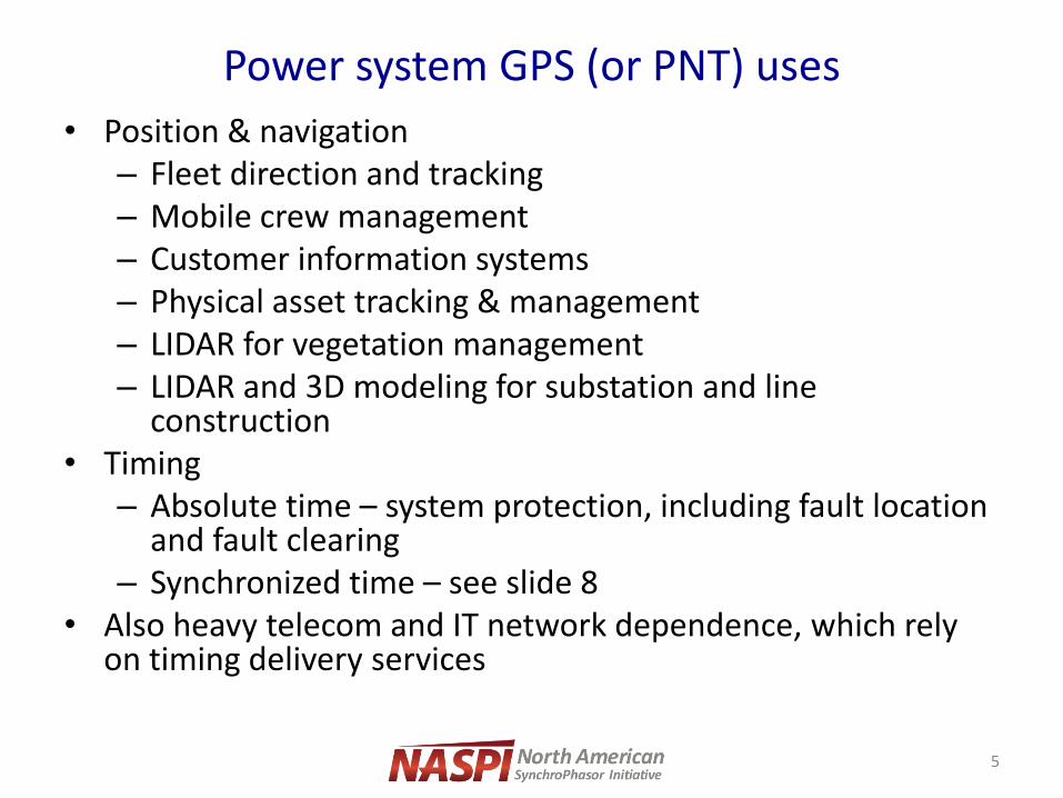
Power system GPS (or PNT) uses
• Position & navigation – Fleet direction and tracking – Mobile crew management – Customer information systems – Physical asset tracking & management – LIDAR for vegetation management – LIDAR and 3D modeling for substation and line
construction • Timing
– Absolute time – system protection, including fault location and fault clearing
– Synchronized time – see slide 8 • Also heavy telecom and IT network dependence, which rely
on timing delivery services
5
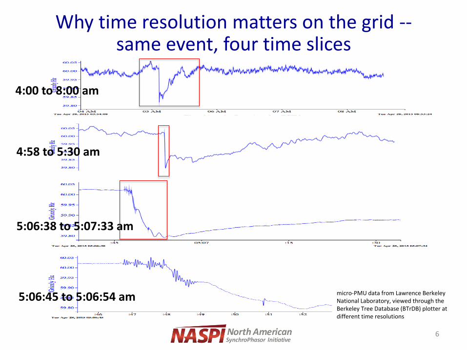
Why time resolution matters on the grid -- same event, four time slices
6
Pacific DC Intertie Trip April 28, 2015
Pacific DC Intertie Trip April 28, 2015
4:00 to 8:00 am
4:58 to 5:30 am
5:06:38 to 5:07:33 am
5:06:45 to 5:06:54 am micro-PMU data from Lawrence Berkeley National Laboratory, viewed through the Berkeley Tree Database (BTrDB) plotter at different time resolutions

Why time resolution matters on the grid – same event, two time slices
7
Wind Farm Oscillations
• Only during high winds
• FFT analysis shows 13-14Hz
• Voltage fluctuations as high as 5%
• Interaction between wind farms?
• Switching performed to electrically isolate the wind farms
• Determined it was a problem at different wind farms with the same turbine model
• The only solution was to curtail output
20
(35 minutes)
(2 seconds)
Source: OG&E, “Synchrophasors at OG+E,” Austin White, IEEE PES GM 2016

Inter-area oscillations in Western Interconnection
-5 0 5 10 15 20 2559.98
59.99
60
60.01
60.02
60.03
60.04
60.05
60.06
Time (sec)
Fre
quency (
Hz)
Western Interconnection Frequencies - August 4 2000 Oscillation
Grand Coulee
Malin
Devers
Aligning synchronized wide-area measurements from multiple locations reveals the power system’s dynamic state; you can’t see and analyze these oscillations from slower SCADA data or from unsynchronized local PMU measurements. Timing errors cause false conclusions about grid conditions.
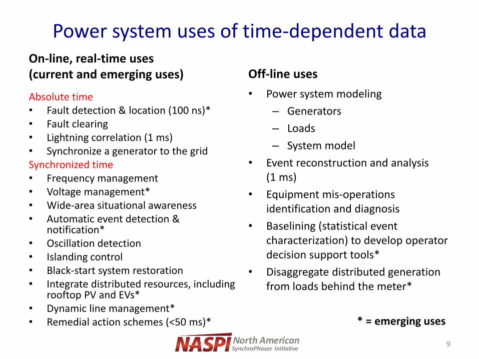
Power system uses of time-dependent data On-line, real-time uses (current and emerging uses)
Absolute time • Fault detection & location (100 ns)* • Fault clearing • Lightning correlation (1 ms) • Synchronize a generator to the grid Synchronized time • Frequency management • Voltage management* • Wide-area situational awareness • Automatic event detection &
notification* • Oscillation detection • Islanding control • Black-start system restoration • Integrate distributed resources, including
rooftop PV and EVs* • Dynamic line management* • Remedial action schemes (<50 ms)*
Off-line uses
• Power system modeling
– Generators
– Loads
– System model
• Event reconstruction and analysis (1 ms)
• Equipment mis-operations identification and diagnosis
• Baselining (statistical event characterization) to develop operator decision support tools*
• Disaggregate distributed generation from loads behind the meter*
9
* = emerging uses
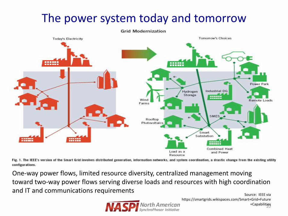
The power system today and tomorrow
10
Source: IEEE via https://smartgrids.wikispaces.com/Smart+Grid+Future
+Capabilities
One-way power flows, limited resource diversity, centralized management moving toward two-way power flows serving diverse loads and resources with high coordination and IT and communications requirements
Some of the ways timing goes bad from the grid user’s perspective
• From space – Ionospheric problems – sunspots, geomagnetic disturbances – Events – leap seconds, satellite constellation changes
• On-site
– GPS receiver – poor quality, software bugs, no firmware updates, bad location, local jamming or spoofing or other radio interference, lost wire to the PMU, no correction for PNT broadcast problems
– PMU – poor interoperability with GPS receiver, slow firmware patches, lost wire to GPS receiver, sloppy program for time-handling, no detection of timing problems, no back-up time source
– In substation timing delivery (rare) – problems with cabling or ethernet distribution of time signal to slave clocks
• Phasor Data Concentrator and applications – inadequate detection of timing anomalies or gaps and computational errors resulting from those problems. Also sometimes inadequate timing standards and protocols…
11
What happens to synchrophasor measurements if GPS goes bad?
• If there is an error or spoof of the time signal to a phasor measurement unit (PMU), that error will cause false calculations of phase angle and mis-alignment of measured grid conditions relative to other PMUs
• In the case of the leap second:
– Where the GPS clocks skipped the second or were early/late, PMU measurements were too early or too late, causing PDCs to ignore the PMU measurements
– Where there were duplicate time stamps, there were “duplicate” PMU measurements
– Phase angle error depends on accurate time information; bad time stamps mean erroneous phase angle calculation
*** These are all PMU or PMU-clock problems, not GPS problems – but the user doesn’t recognize that…
12
Calculating phase angle with a time error
13
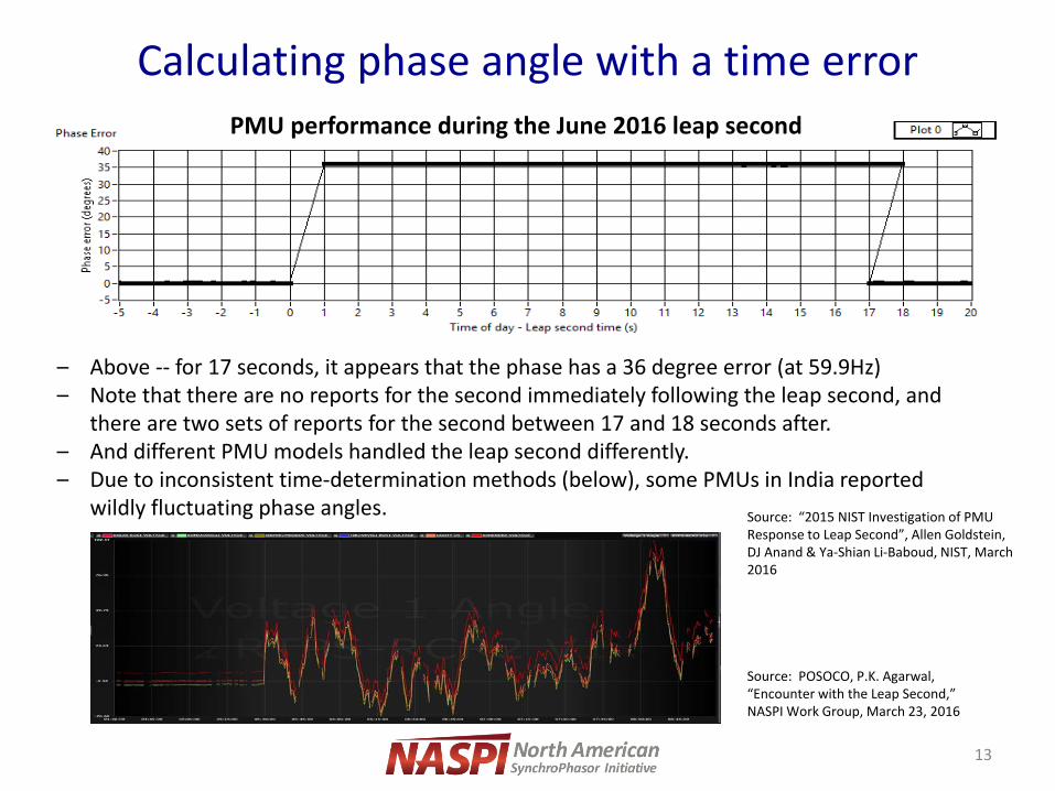
PMU performance during the June 2016 leap second
Source: “2015 NIST Investigation of PMU Response to Leap Second”, Allen Goldstein, DJ Anand & Ya-Shian Li-Baboud, NIST, March 2016
– Above -- for 17 seconds, it appears that the phase has a 36 degree error (at 59.9Hz) – Note that there are no reports for the second immediately following the leap second, and
there are two sets of reports for the second between 17 and 18 seconds after. – And different PMU models handled the leap second differently. – Due to inconsistent time-determination methods (below), some PMUs in India reported
wildly fluctuating phase angles.
Source: POSOCO, P.K. Agarwal, “Encounter with the Leap Second,” NASPI Work Group, March 23, 2016
23 March 2016 Encounter with Leap Second 6
Random changes observed in trend of angular
difference in some PMUs after 23:29 at National
Control Center.
Encounter with Leap Second - 28th June’15
Power system punchlines • Timing errors from the time source can cause
incorrect synchrophasor data – Such errors can create false analytical conclusions and in
the future could drive undesirable and possibly dangerous automated grid operations with synchrophasor-based controls
• The power sector needs to protect future grid operations with better timing tools and practices to improve robustness and resilience – We need to assume that PNT could be unreliable at both
source and receiving points
– We need to start implementing measures to assure accurate, reliable time stamps against multiple failure modes
14

Some timing remedies and options At the PNT level:
• Improved signal robustness checks
• Multi-frequency – L1 C/A, L2C, L5 (but multi-frequency receivers are expensive)
• Multi-system – GPS, GLONASS, GALILEO, eLoran, good internal oscillators
• Multiple receivers
• Jamming, spoofing and interference detection and/or prevention
GPS-independent networks:
• Telecom network is capable of time transfer -- avoids dependence on satellites and transmitter sites and requirement for large receiver network installation and maintenance
• Network-distributed time can receive accurate time from multiple sources (GPS, NTP, CDMA, PTP), some IRIG-B
• Distributed clock networks, some IEEE 1588
• Holdover clocks in key devices for short-term back-up
15
What we’re doing about it –
NASPI Time Synchronization Task Force
Scope – Time synchronization awareness and problem-solving for electric sector, with synchrophasor focus • Document problems of current PNT solutions
• Identify specific, near-term solutions and mitigations that can address multiple failure causes (redundant timing sources, better installation and maintenance practices, detection of bad or anomalous time signals, specs for good-quality equipment, etc.)
• Develop and share how-to information for these solutions
• Recommendations for longer-term research needs (timing problem detection, equipment interoperability, standards updates, etc.) within grid sector and beyond
16
![NASPI for NERC OC 121212.pptx [Read-Only] · 2019. 2. 22. · Title: Microsoft PowerPoint - NASPI for NERC OC 121212.pptx [Read-Only] Author: D3P345 Created Date: 12/16/2011 1:36:49](https://img.pdfslide.us/doc/110x75/60cfcc177baddb0e533a9551/naspi-for-nerc-oc-read-only-2019-2-22-title-microsoft-powerpoint-naspi.jpg)