Embed Size (px)
Citation preview
ELEC 6740: Electronics Manufacturing Chapter 12: Soldering of Surface Mount Components
R. Wayne JohnsonAlumni Professor
ECE Department, Auburn University
Subjects! Introduction! Wave Soldering! Vapor Phase Reflow Soldering! Infrared Reflow Soldering! Convection Reflow Soldering! Soldering Defects! Alternate Soldering Methods
Introduction! Soldering - Low temperature! Brazing – Medium temperature! Welding – High temperature
Wave Soldering! Through hole components! SMT resistors, capacitors, diodes, SOTs! SOICs more difficult! PLCCs and PQFPs should be avoided
Wave Solder! Flux application
! Foam! Spray! Jet
! Preheat! Minimize thermal shock to board! Activate flux
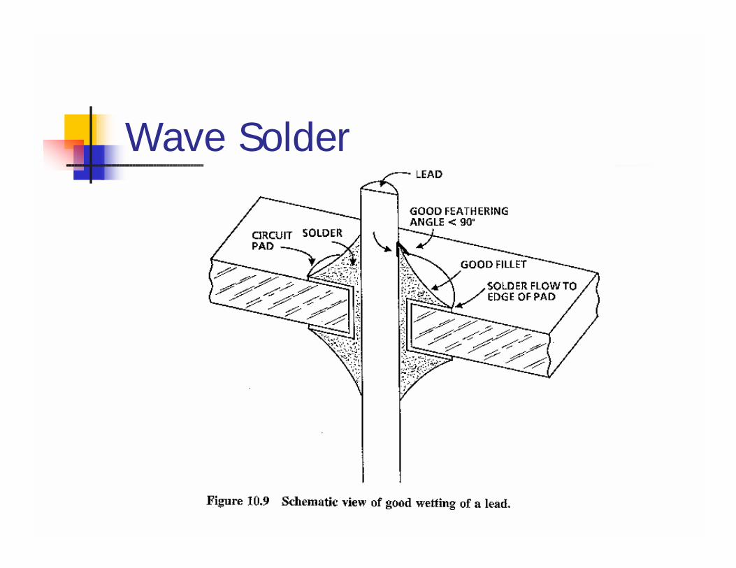
! Solder wave! Provide solder alloy! Form metallurgical connections
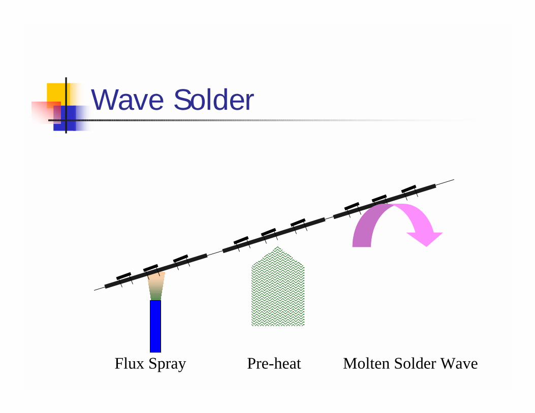
Wave Solder
Flux Spray Pre-heat Molten Solder Wave
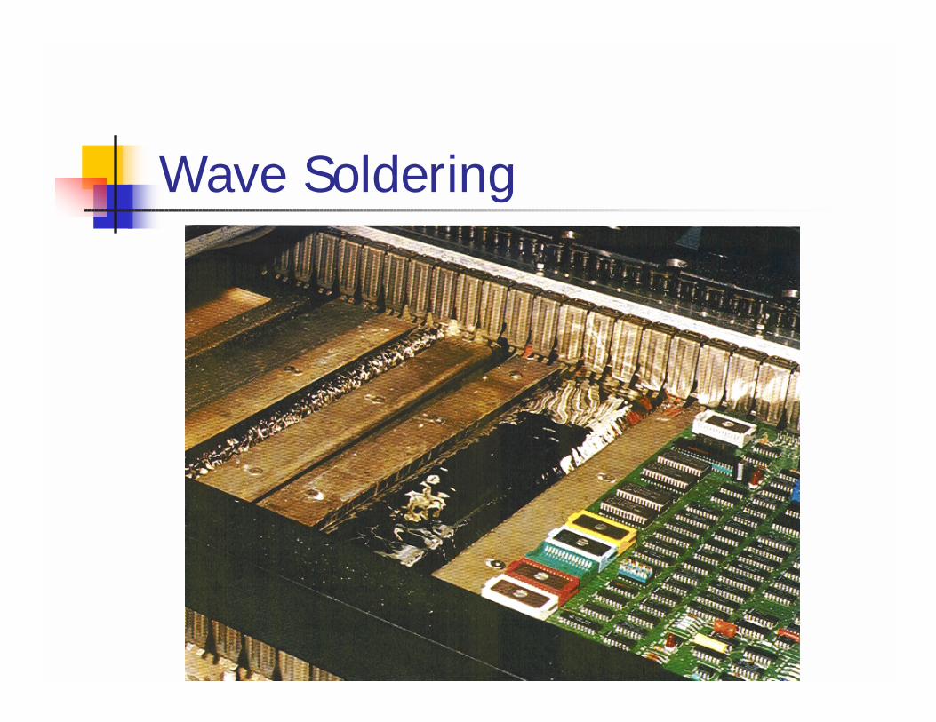
Wave Soldering
Wave Solder
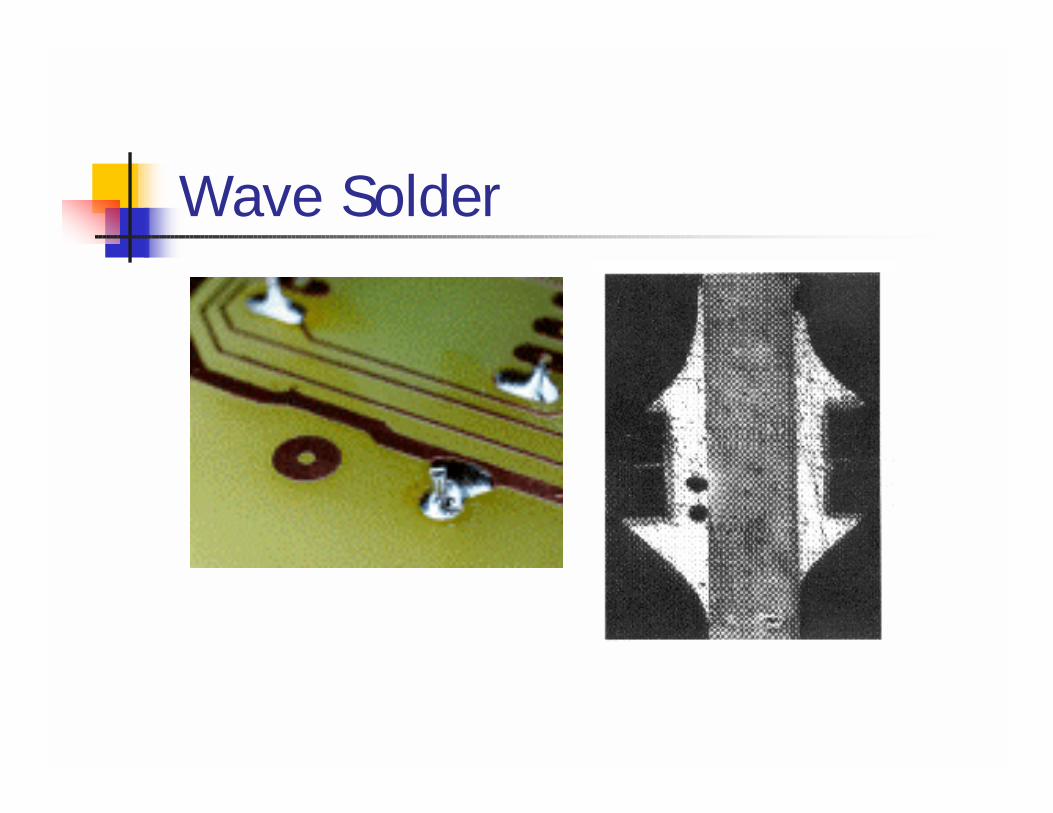
Wave Solder
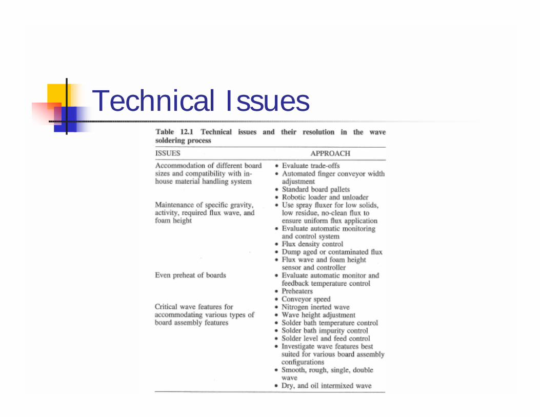
Technical Issues
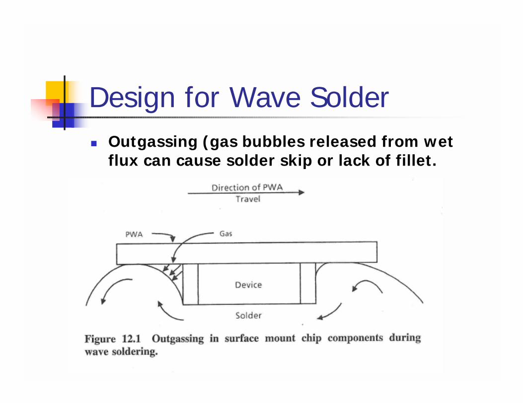
Design for Wave Solder! Outgassing (gas bubbles released from wet
flux can cause solder skip or lack of fillet.
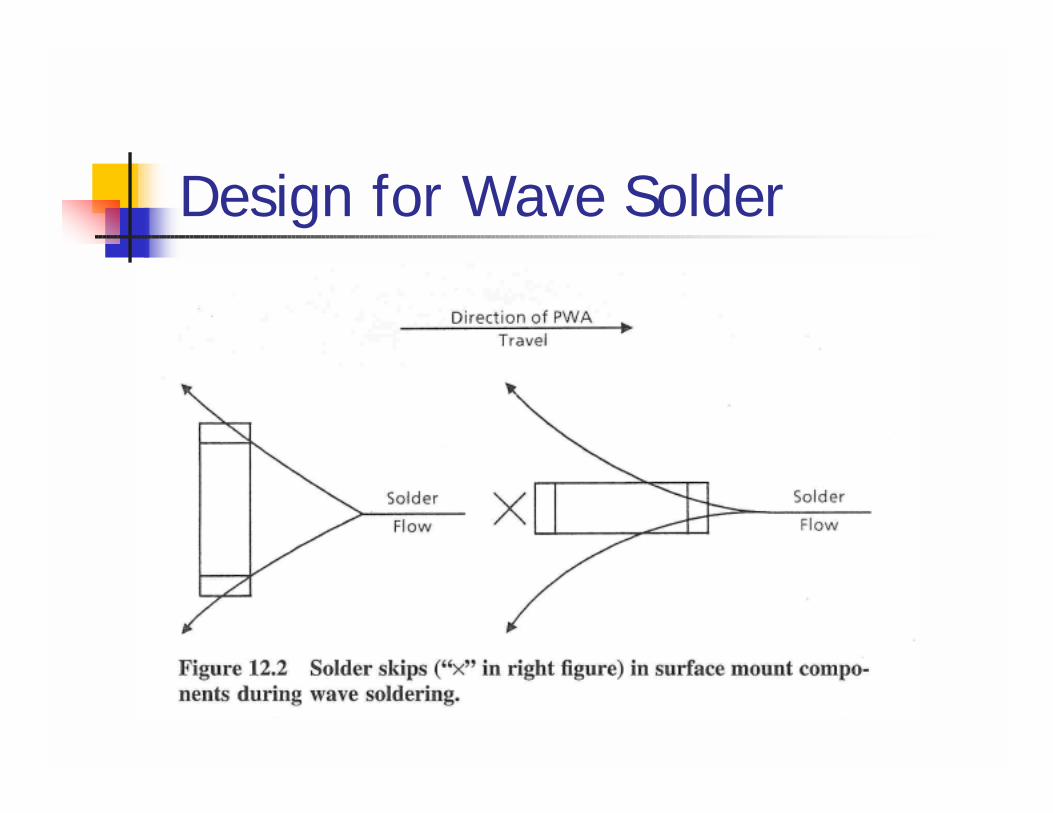
Design for Wave Solder
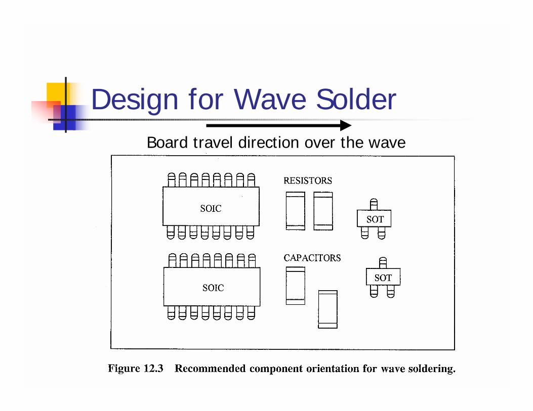
Design for Wave SolderBoard travel direction over the wave
Wave Soldering! Bridges can occur beneath small chips
(0805, 0603, 0402, 0201)! Capillary action between glue dots! Only liquid photoimageable solder mask is
recommended bewteen pads
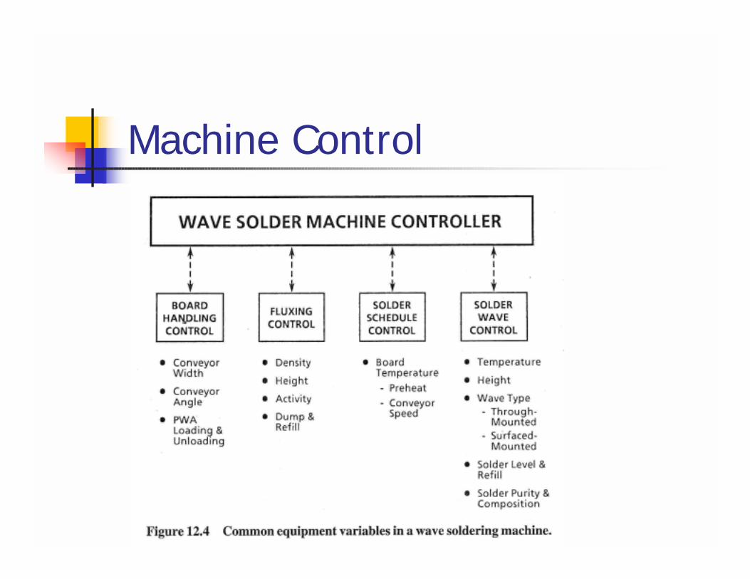
Machine Control
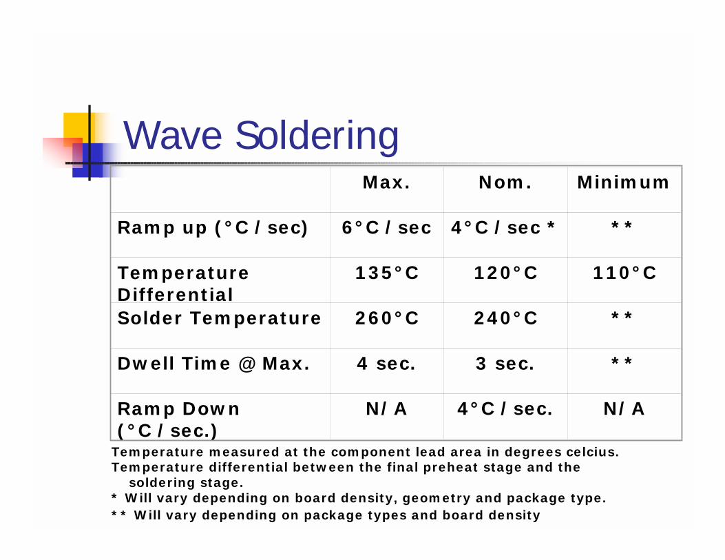
Wave SolderingMax. Nom. Minimum
Ramp up (°C /sec) 6°C /sec 4°C /sec * **
Temperature Differential
135°C 120°C 110°C
Solder Temperature 260°C 240°C **
Dwell Time @ Max. 4 sec. 3 sec. **
Ramp Down (°C /sec.)
N/A 4°C /sec. N/A
Temperature measured at the component lead area in degrees celcius.Temperature differential between the final preheat stage and the
soldering stage.* Will vary depending on board density, geometry and package type.** Will vary depending on package types and board density
Wave Soldering! Capacitor cracking
! Delta between the wave and the preheat should be 100-120oC
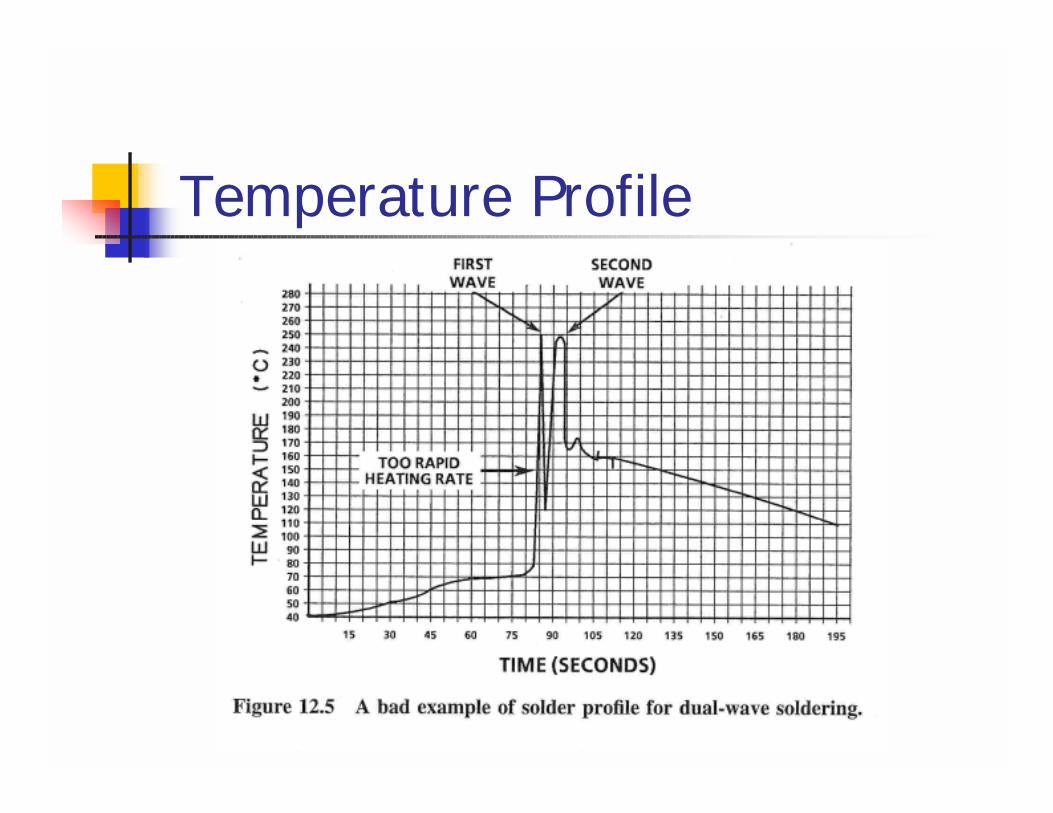
Temperature Profile
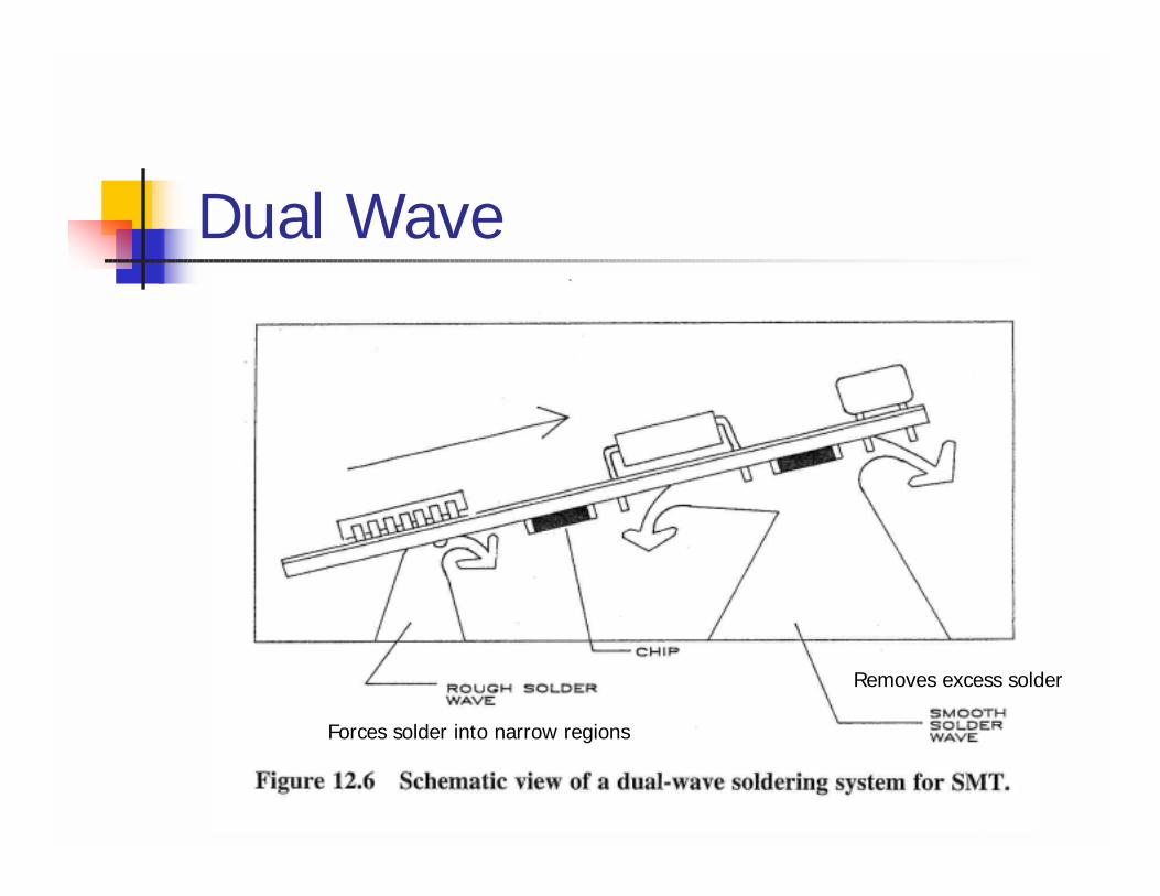
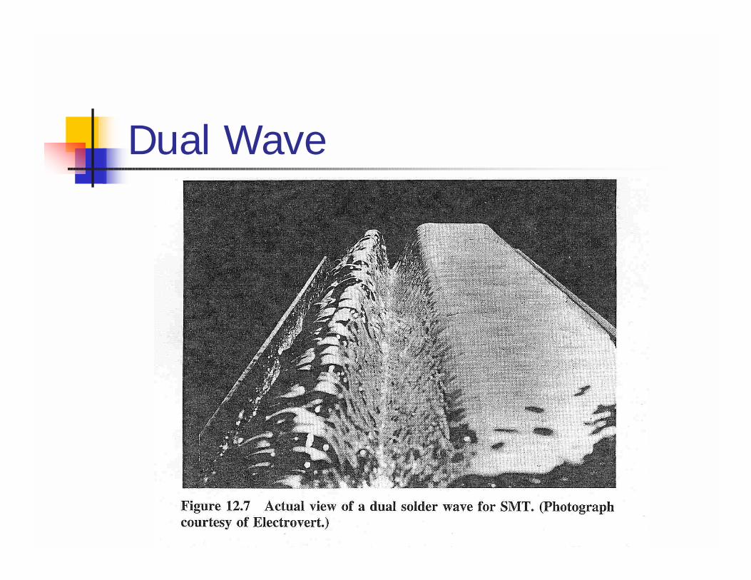
Dual Wave
Forces solder into narrow regions
Removes excess solder
Dual Wave
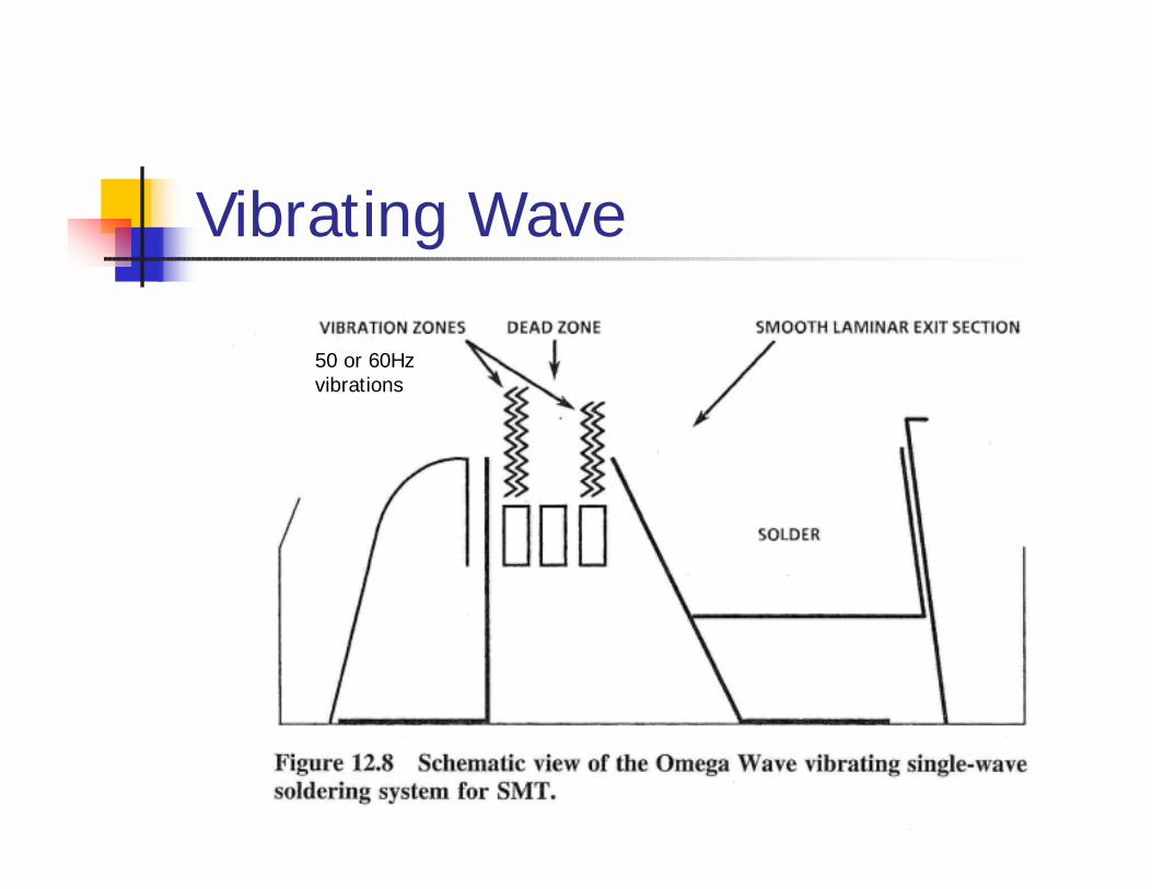
Vibrating Wave
50 or 60Hzvibrations
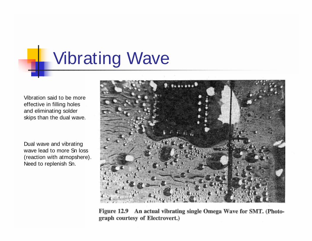
Vibrating Wave
Vibration said to be moreeffective in filling holesand eliminating solderskips than the dual wave.
Dual wave and vibrating wave lead to more Sn loss(reaction with atmopshere).Need to replenish Sn.
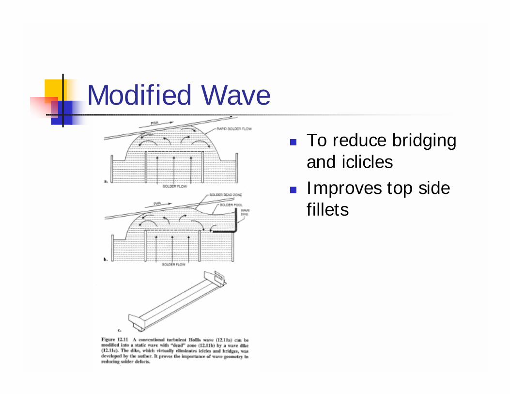
Modified Wave! To reduce bridging
and iclicles! Improves top side
fillets
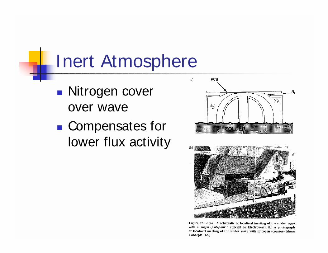
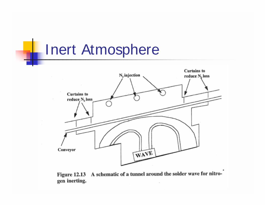
Inert Atmosphere! Nitrogen cover
over wave! Compensates for
lower flux activity
Inert Atmosphere
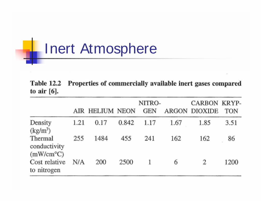
Inert Atmosphere
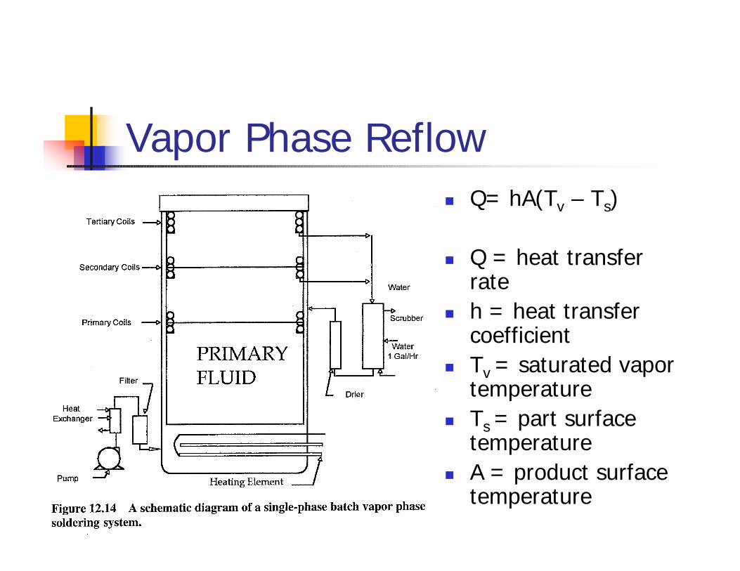
Vapor Phase Reflow! Q= hA(Tv – Ts)
! Q = heat transfer rate
! h = heat transfer coefficient
! Tv = saturated vapor temperature
! Ts = part surface temperature
! A = product surface temperature
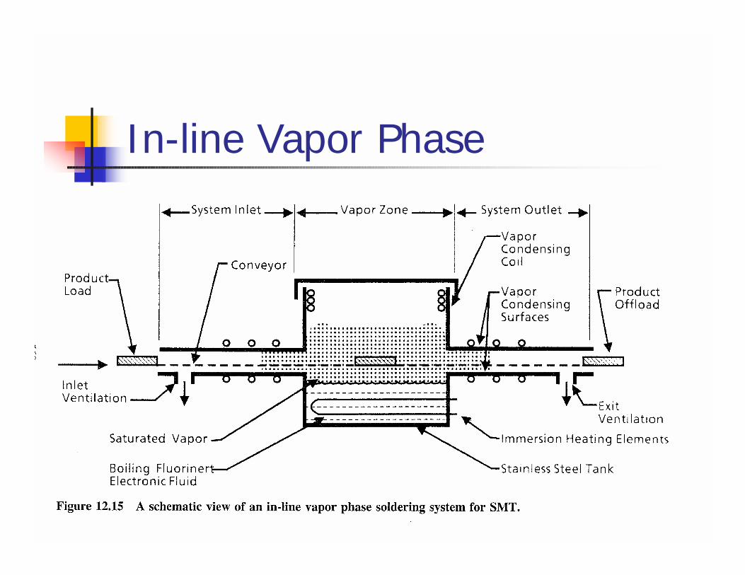
In-line Vapor Phase
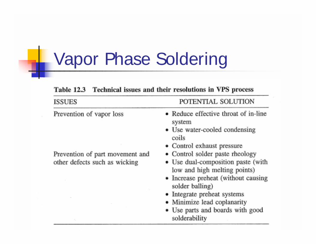
Vapor Phase Soldering
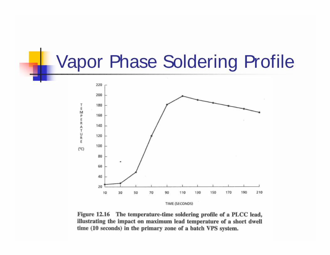
Vapor Phase Soldering Profile
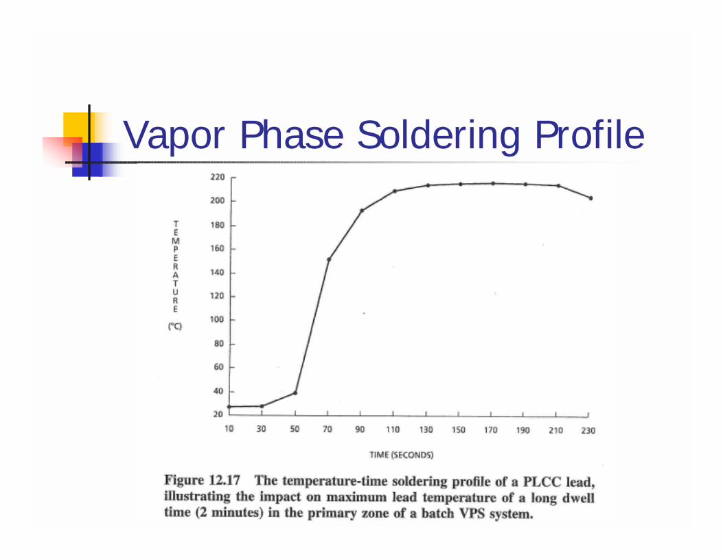
Vapor Phase Soldering Profile
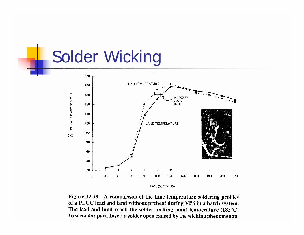
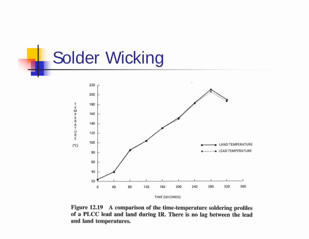
Solder Wicking
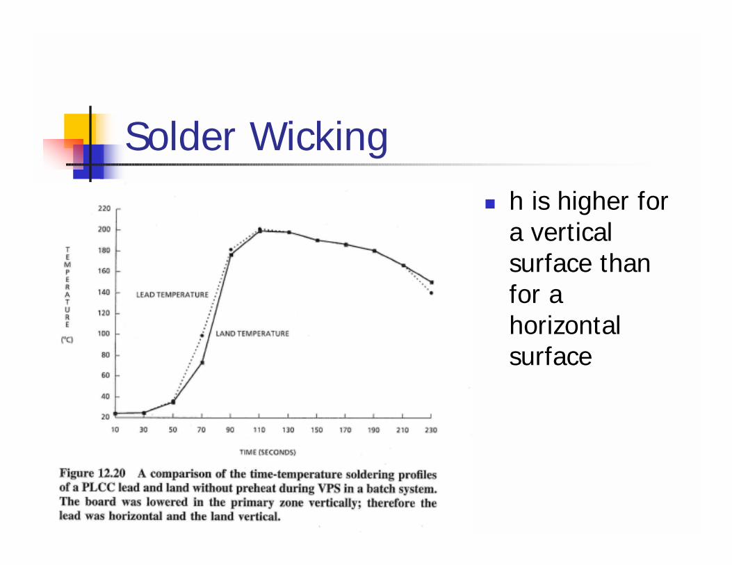
Solder Wicking! h is higher for
a vertical surface than for a horizontal surface
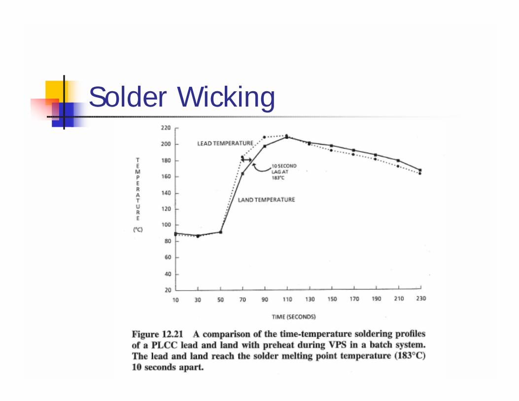
Solder Wicking
Infrared Reflow Soldering! Class I: Radiant IR dominant system! Class II: Convection/IR dominant
system! Class III: Convection dominant systems
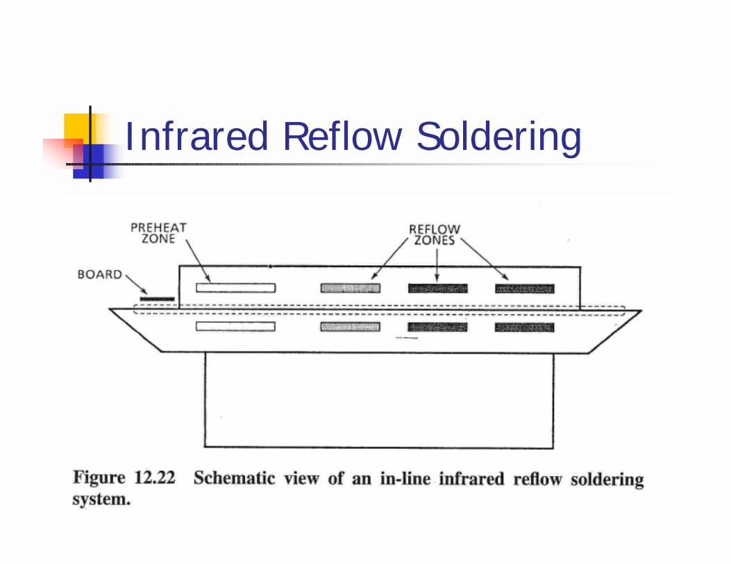
Infrared Reflow Soldering
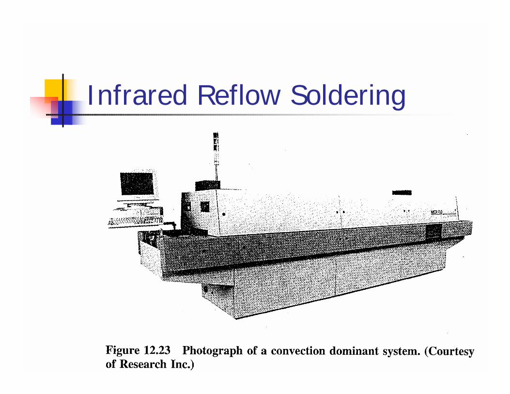
Infrared Reflow Soldering
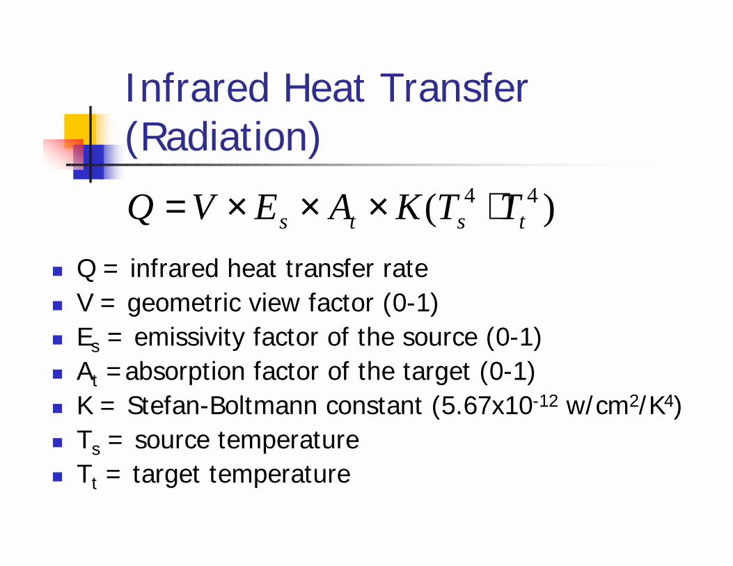
Infrared Heat Transfer (Radiation)
! Q = infrared heat transfer rate! V = geometric view factor (0-1)! Es = emissivity factor of the source (0-1)! At =absorption factor of the target (0-1)! K = Stefan-Boltmann constant (5.67x10⁻¹² w/cm2/K4)! Ts = source temperature! Tt = target temperature
)( 44tsts TTKAEVQ ⋅×××=
Solder Wicking
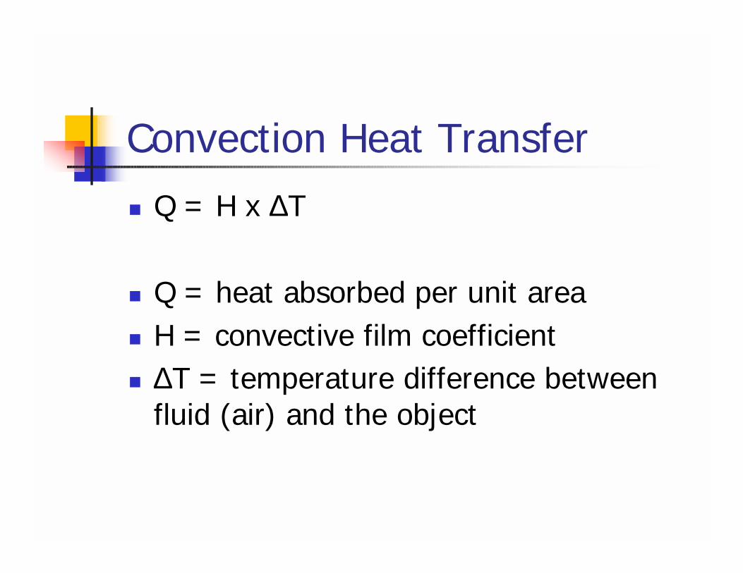
Convection Heat Transfer! Q = H x ∆T
! Q = heat absorbed per unit area! H = convective film coefficient! ∆T = temperature difference between
fluid (air) and the object
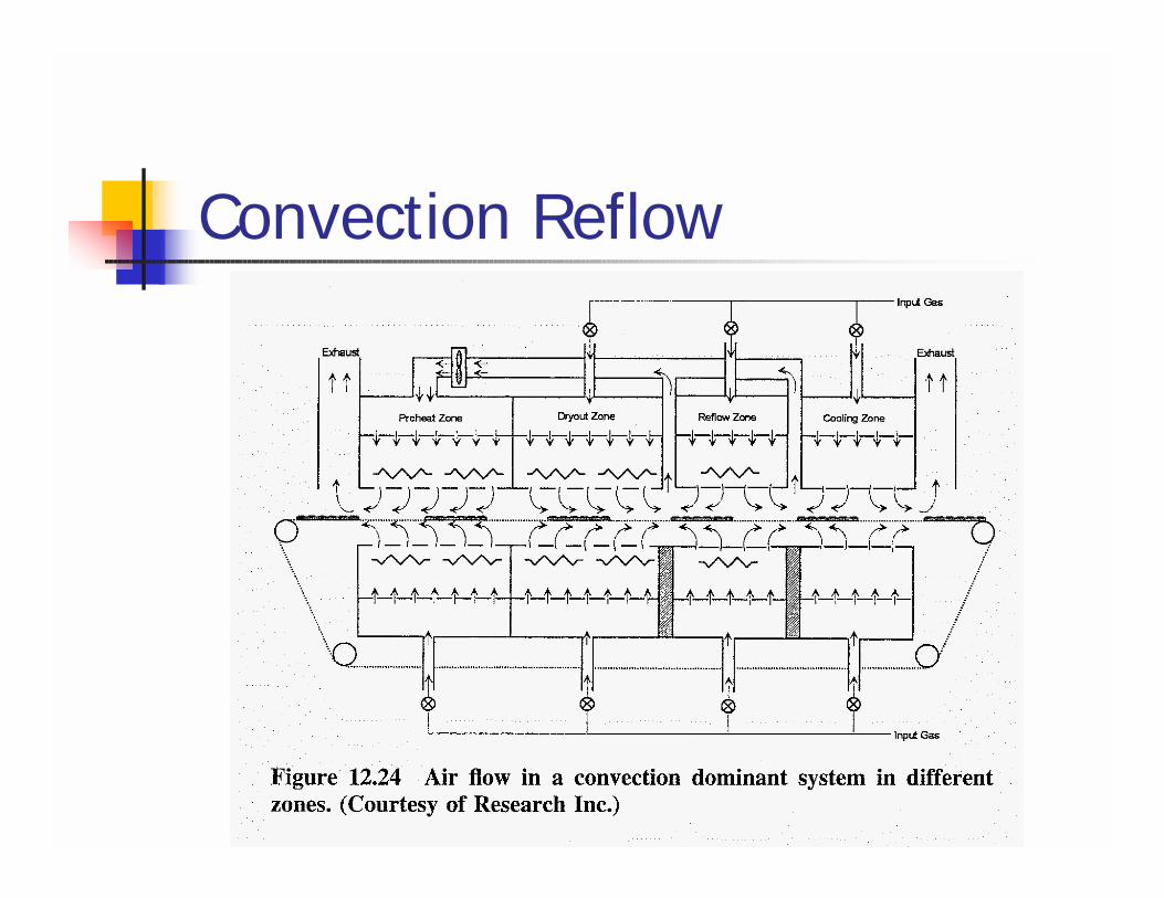
Convection Reflow
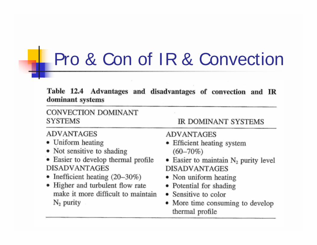
Pro & Con of IR & Convection
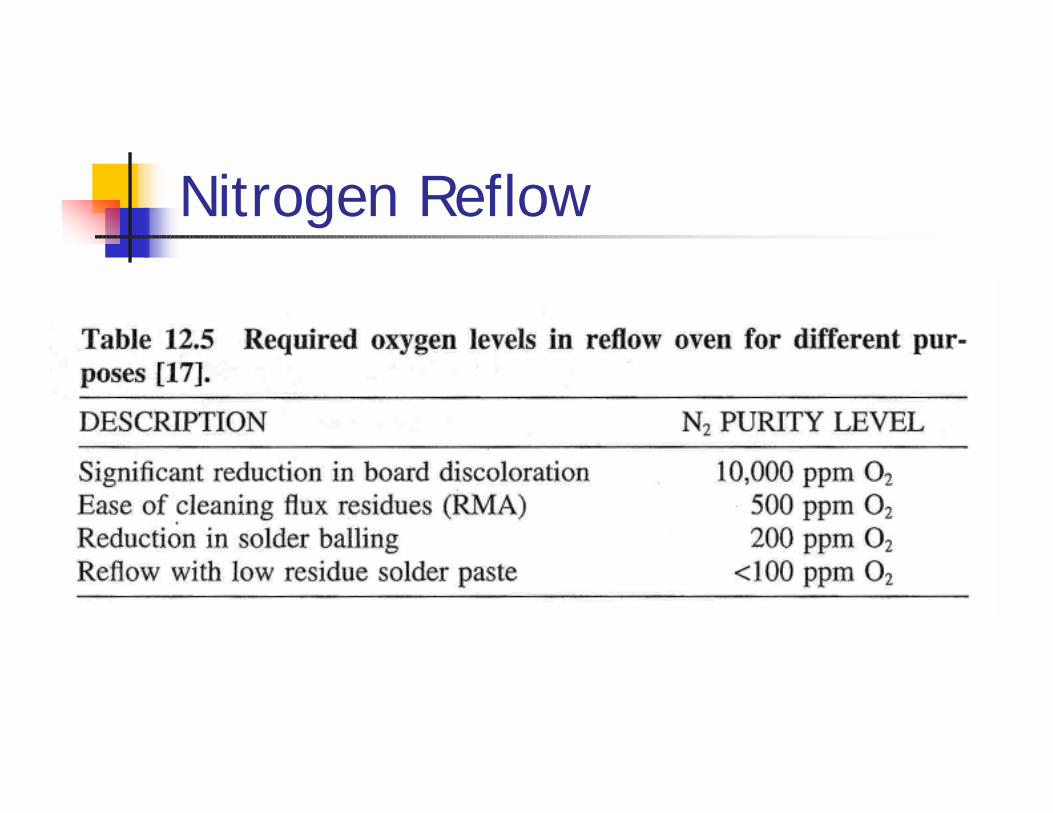
Nitrogen Reflow
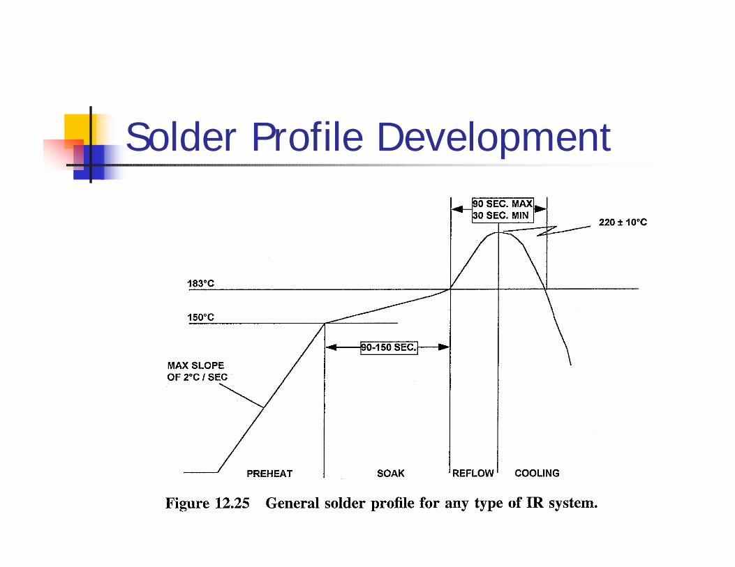
Solder Profile Development
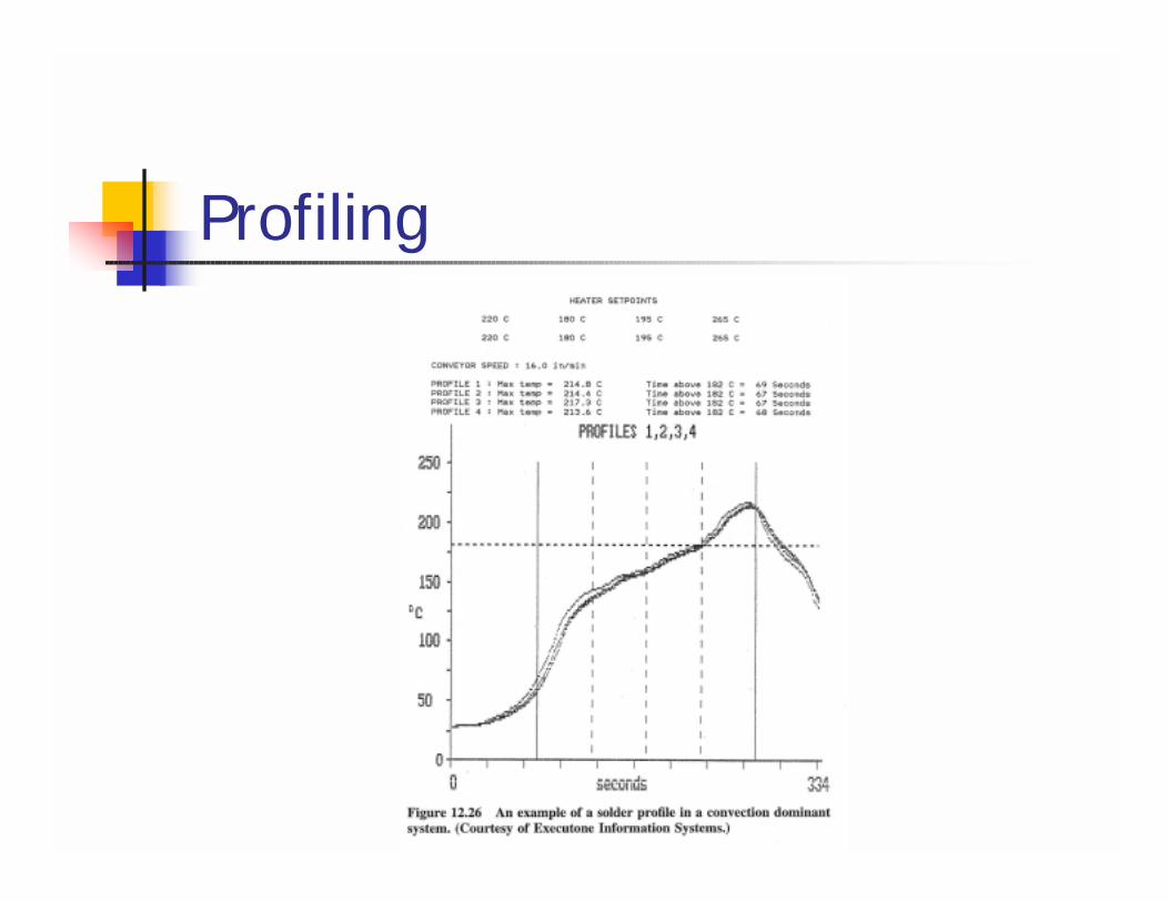
Profiling
Common Reflow Defects! Tombstoning and Part Movement
! If heating rate is too high, the volatiles in the solder paste will rapidly evolve, possibly causing tombstoning (standing on end), drawbridging (standing at an angle) or lateral shift.
! Poor design! Poor solder wetting
Common Reflow Defects! Thermal shock
! Rapid heating or cooling rates! Part surface temperature is higher than
interior! Component cracking
! Solder mask discoloration! Especially dry film solder masks in IR
dominant systems
Laser Soldering! Selective heating for temperature
sensitive components! Heats the solder only and not the
component
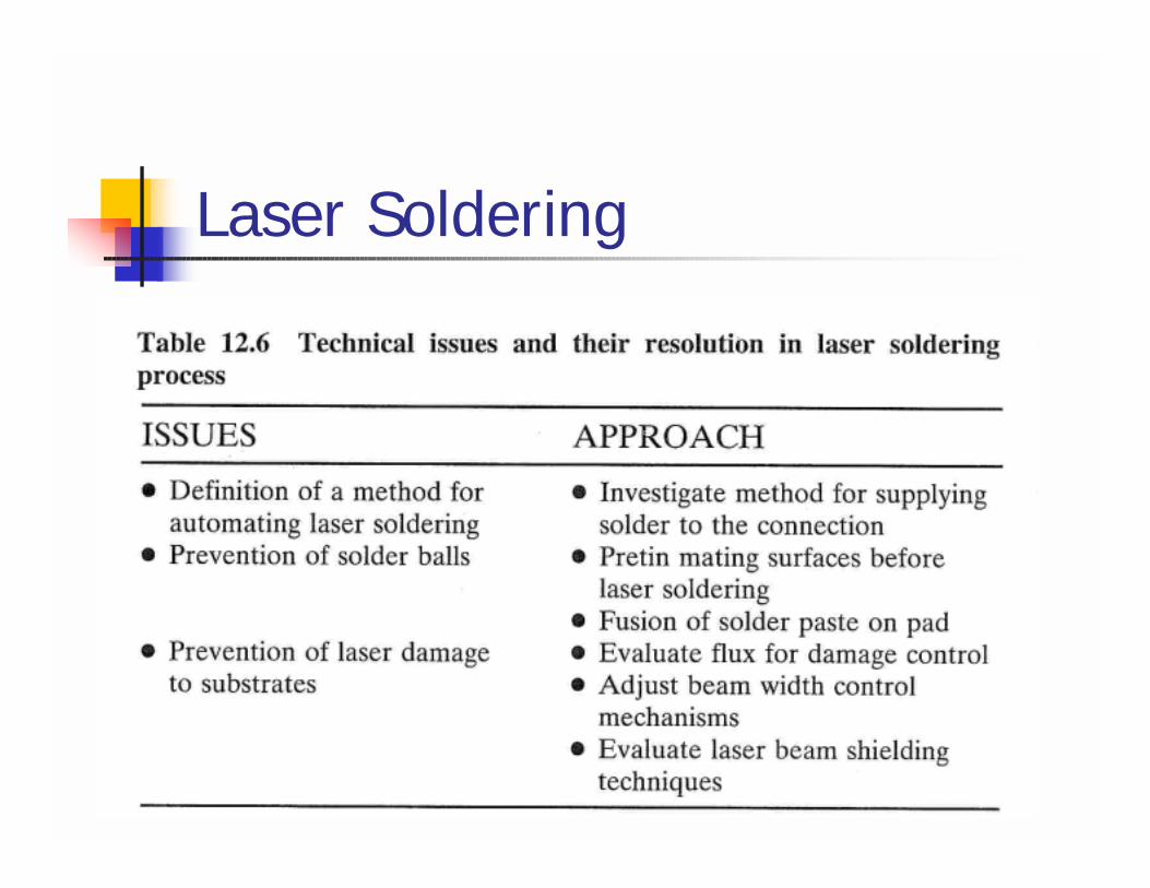
Laser Soldering
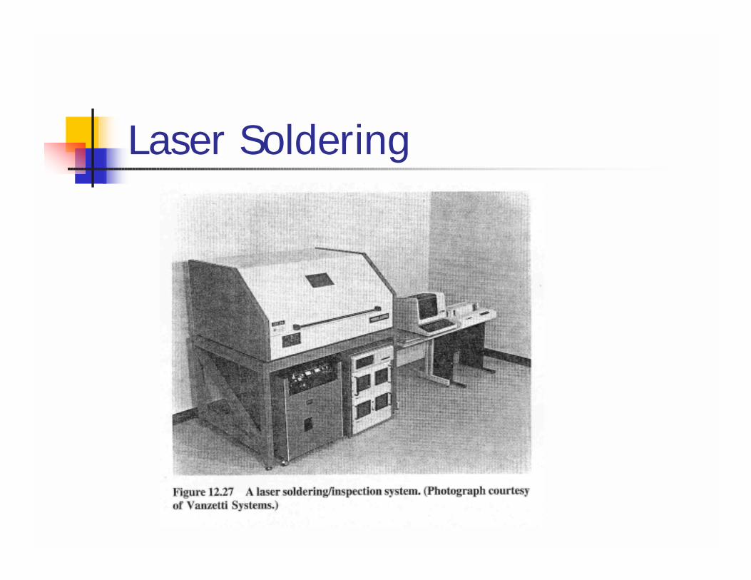
Laser Soldering
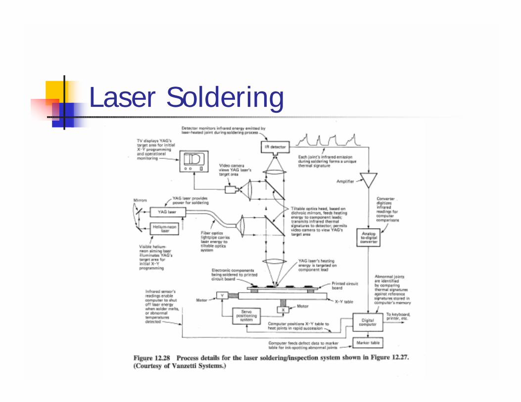
Laser Soldering
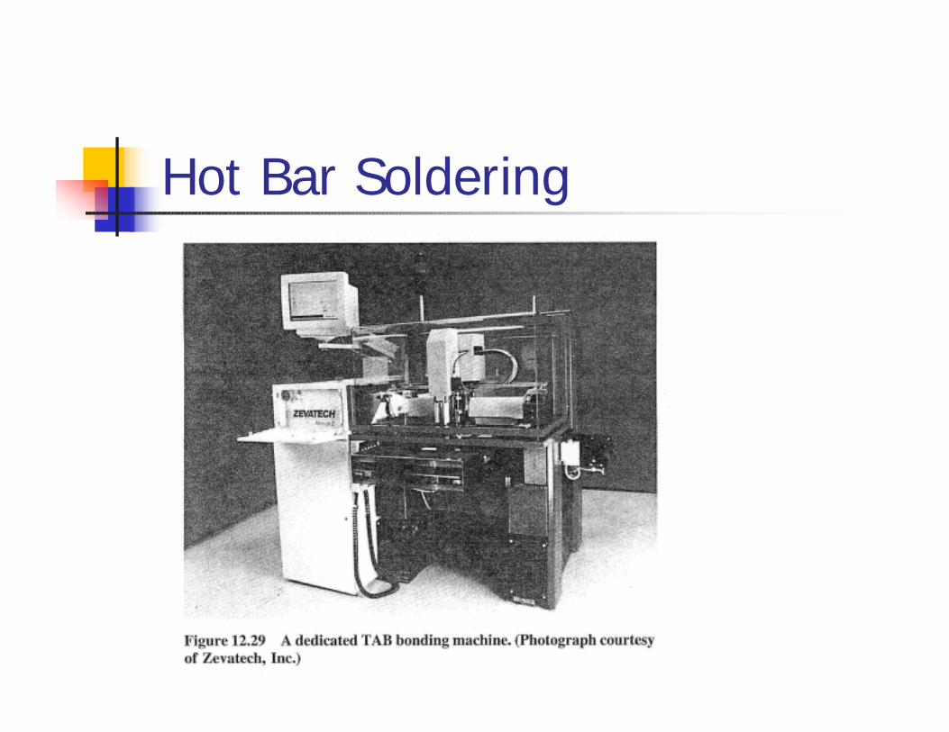
Hot Bar Soldering
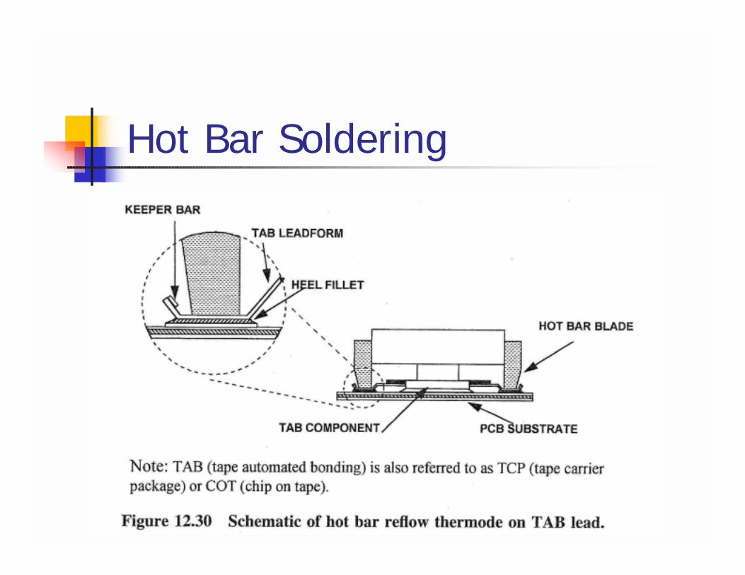
Hot Bar Soldering
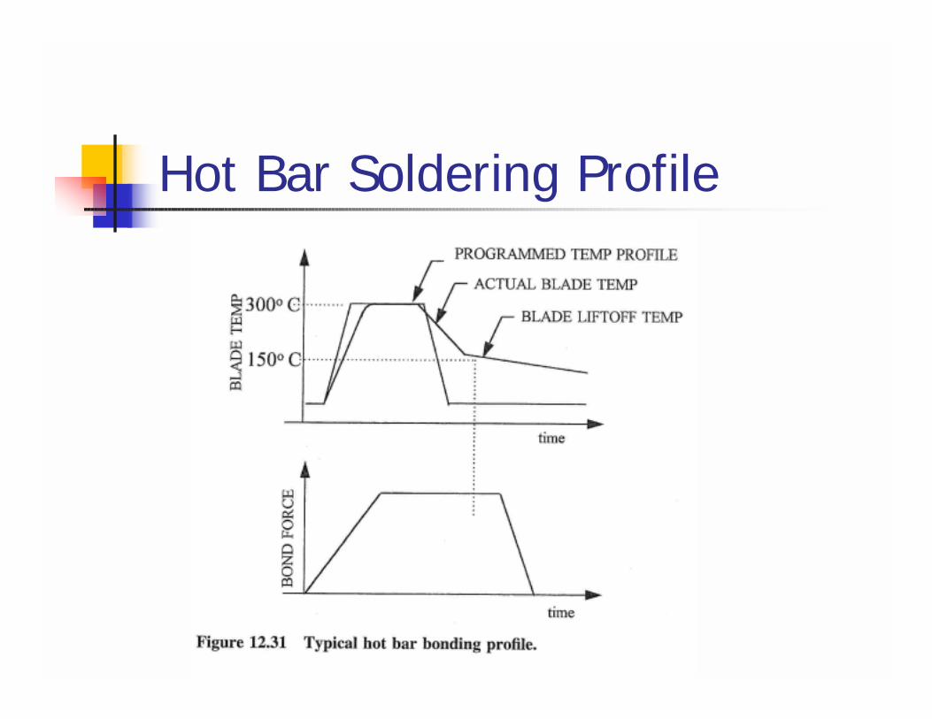
Hot Bar Soldering Profile
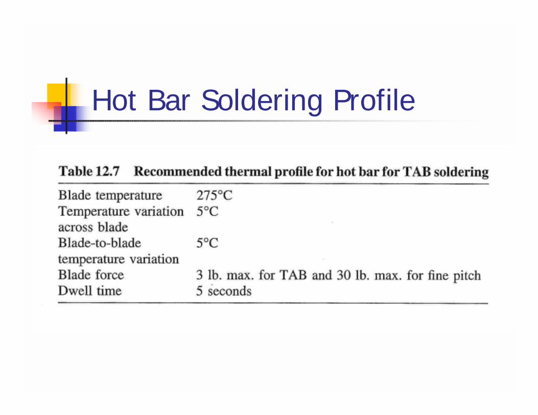
Hot Bar Soldering Profile
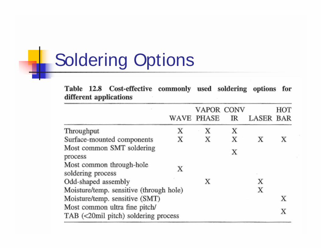
Soldering Options