Embed Size (px)
Citation preview
53-1002829-0328 August 2014
®
Brocade VDX 6740Hardware Reference Manual
Supporting the Brocade VDX 6740, VDX 6740T, and VDX 6740T-1G
Copyright © 2014 Brocade Communications Systems, Inc. All Rights Reserved.
Brocade, the B-wing symbol, Brocade Assurance, ADX, AnyIO, DCX, Fabric OS, FastIron, HyperEdge, ICX, MLX, MyBrocade, NetIron, OpenScript, VCS, VDX, and Vyatta are registered trademarks, and The Effortless Network and the On-Demand Data Center are trademarks of Brocade Communications Systems, Inc., in the United States and in other countries. Other brands and product names mentioned may be trademarks of others.
Notice: This document is for informational purposes only and does not set forth any warranty, expressed or implied, concerning any equipment, equipment feature, or service offered or to be offered by Brocade. Brocade reserves the right to make changes to this document at any time, without notice, and assumes no responsibility for its use. This informational document describes features that may not be currently available. Contact a Brocade sales office for information on feature and product availability. Export of technical data contained in this document may require an export license from the United States government.
The authors and Brocade Communications Systems, Inc. assume no liability or responsibility to any person or entity with respect to the accuracy of this document or any loss, cost, liability, or damages arising from the information contained herein or the computer programs that accompany it.
The product described by this document may contain open source software covered by the GNU General Public License or other open source license agreements. To find out which open source software is included in Brocade products, view the licensing terms applicable to the open source software, and obtain a copy of the programming source code, please visit http://www.brocade.com/support/oscd.
Brocade Communications Systems, Incorporated
Document History
Corporate and Latin American HeadquartersBrocade Communications Systems, Inc.130 Holger WaySan Jose, CA 95134 Tel: 1-408-333-8000 Fax: 1-408-333-8101 E-mail: [email protected]
Asia-Pacific HeadquartersBrocade Communications Systems China HK, Ltd.No. 1 Guanghua RoadChao Yang DistrictUnits 2718 and 2818Beijing 100020, ChinaTel: +8610 6588 8888Fax: +8610 6588 9999E-mail: [email protected]
European HeadquartersBrocade Communications Switzerland SàrlCentre SwissairTour B - 4ème étage29, Route de l'AéroportCase Postale 105CH-1215 Genève 15Switzerland Tel: +41 22 799 5640Fax: +41 22 799 5641E-mail: [email protected]
Asia-Pacific HeadquartersBrocade Communications Systems Co., Ltd. (Shenzhen WFOE)Citic PlazaNo. 233 Tian He Road NorthUnit 1308 – 13th FloorGuangzhou, ChinaTel: +8620 3891 2000Fax: +8620 3891 2111E-mail: [email protected]
Title Publication number Summary of changes Date
Brocade VDX 6740 Hardware Reference Manual
53-1002929-01 New document July 2013
Brocade VDX 6740 Hardware Reference Manual
53-1002929-02 Revised with information for Brocade 6740T-1G
February 2014
Brocade VDX 6740 Hardware Reference Manual
53-1002829-03 Revised with information for Network OS 5.0.0 features. Enhanced information and made corrections.
August 2014
Contents
About This Document
In this chapter . . . . . . . . . . . . . . . . . . . . . . . . . . . . . . . . . . . . . . . . . . . vii
How this document is organized . . . . . . . . . . . . . . . . . . . . . . . . . . . . vii
What’s new in this document . . . . . . . . . . . . . . . . . . . . . . . . . . . . . . . viii
Supported hardware and software . . . . . . . . . . . . . . . . . . . . . . . . . . viii
Document conventions. . . . . . . . . . . . . . . . . . . . . . . . . . . . . . . . . . . . viiiText formatting . . . . . . . . . . . . . . . . . . . . . . . . . . . . . . . . . . . . . . . viiiCommand syntax conventions . . . . . . . . . . . . . . . . . . . . . . . . . . viiiNotes, cautions, and warnings . . . . . . . . . . . . . . . . . . . . . . . . . . . ixKey terms . . . . . . . . . . . . . . . . . . . . . . . . . . . . . . . . . . . . . . . . . . . . ix
Notice to the reader . . . . . . . . . . . . . . . . . . . . . . . . . . . . . . . . . . . . . . . x
Additional information. . . . . . . . . . . . . . . . . . . . . . . . . . . . . . . . . . . . . . xBrocade resources. . . . . . . . . . . . . . . . . . . . . . . . . . . . . . . . . . . . . xOther industry resources . . . . . . . . . . . . . . . . . . . . . . . . . . . . . . . . x
Getting technical help . . . . . . . . . . . . . . . . . . . . . . . . . . . . . . . . . . . . . . xi
Document feedback . . . . . . . . . . . . . . . . . . . . . . . . . . . . . . . . . . . . . . . xi
Chapter 1 Brocade VDX 6740 Introduction
In this chapter . . . . . . . . . . . . . . . . . . . . . . . . . . . . . . . . . . . . . . . . . . . . 1
Brocade VDX 6740 overview . . . . . . . . . . . . . . . . . . . . . . . . . . . . . . . . 1FlexPort. . . . . . . . . . . . . . . . . . . . . . . . . . . . . . . . . . . . . . . . . . . . . . 2Platform components and capabilities. . . . . . . . . . . . . . . . . . . . . 2Software features . . . . . . . . . . . . . . . . . . . . . . . . . . . . . . . . . . . . . 3
Views of the Brocade VDX 6740 switches . . . . . . . . . . . . . . . . . . . . . . 5
Chapter 2 Brocade VDX 6740 Installation
In this chapter . . . . . . . . . . . . . . . . . . . . . . . . . . . . . . . . . . . . . . . . . . . . 9
Items included with the Brocade VDX 6740 switches . . . . . . . . . . . . 9
Installation and safety considerations. . . . . . . . . . . . . . . . . . . . . . . . . 9Electrical considerations . . . . . . . . . . . . . . . . . . . . . . . . . . . . . . . 10Environmental considerations . . . . . . . . . . . . . . . . . . . . . . . . . . 10Rack considerations . . . . . . . . . . . . . . . . . . . . . . . . . . . . . . . . . . 10Recommendations for cable management . . . . . . . . . . . . . . . . 11Items required for installation. . . . . . . . . . . . . . . . . . . . . . . . . . . 11
Standalone installation for the Brocade VDX 6740 switches . . . . .12
Rack installation options for the Brocade VDX 6740 switches . . . .12
Brocade VDX 6740 Hardware Reference Manual iii53_1002829_03
Providing power to the switch. . . . . . . . . . . . . . . . . . . . . . . . . . . . . . .12
Verifying operation . . . . . . . . . . . . . . . . . . . . . . . . . . . . . . . . . . . . . . .13
Chapter 3 Brocade VDX 6740 Configuration
In this chapter . . . . . . . . . . . . . . . . . . . . . . . . . . . . . . . . . . . . . . . . . . .15
Configuration for the Brocade VDX 6740 switches. . . . . . . . . . . . . .15
Creating a serial connection. . . . . . . . . . . . . . . . . . . . . . . . . . . . . . . . 16
Permanent password assignment . . . . . . . . . . . . . . . . . . . . . . . . . . . 17Changing the default account passwords . . . . . . . . . . . . . . . . . 17
Setting the switch IP address. . . . . . . . . . . . . . . . . . . . . . . . . . . . . . . 17Using DHCP to set the IP address. . . . . . . . . . . . . . . . . . . . . . . . 17Setting a static IP address . . . . . . . . . . . . . . . . . . . . . . . . . . . . .18Stateless IPv6 autoconfiguration . . . . . . . . . . . . . . . . . . . . . . . .18Setting stateless IPv6 autoconfiguration . . . . . . . . . . . . . . . . . .19
Changing the RBridge ID. . . . . . . . . . . . . . . . . . . . . . . . . . . . . . . . . . .19
Changing the VCS ID . . . . . . . . . . . . . . . . . . . . . . . . . . . . . . . . . . . . . .19
Date and time on the Brocade VDX 6740 . . . . . . . . . . . . . . . . . . . . .20Time zones . . . . . . . . . . . . . . . . . . . . . . . . . . . . . . . . . . . . . . . . . .20Time synchronization. . . . . . . . . . . . . . . . . . . . . . . . . . . . . . . . . .20Synchronizing local time using NTP . . . . . . . . . . . . . . . . . . . . . . 21Setting the clock (date and time) manually . . . . . . . . . . . . . . . . 21Setting time zones . . . . . . . . . . . . . . . . . . . . . . . . . . . . . . . . . . . . 21
Network device connections . . . . . . . . . . . . . . . . . . . . . . . . . . . . . . .22Ethernet or Fast Ethernet hubs. . . . . . . . . . . . . . . . . . . . . . . . . .22Workstations, servers, or routers . . . . . . . . . . . . . . . . . . . . . . . .22Network device. . . . . . . . . . . . . . . . . . . . . . . . . . . . . . . . . . . . . . .22Testing connectivity . . . . . . . . . . . . . . . . . . . . . . . . . . . . . . . . . . .22
Brocade inter-switch link trunks. . . . . . . . . . . . . . . . . . . . . . . . . . . . .23Trunking bandwidth limitation for Brocade VDX 6740-1G . . . .23
Upgrading port speeds on the Brocade VDX 6740T-1G . . . . . . . . . . 24
FlexPort configuration. . . . . . . . . . . . . . . . . . . . . . . . . . . . . . . . . . . . .25
Chapter 4 Brocade VDX 6740 Operation
In this chapter . . . . . . . . . . . . . . . . . . . . . . . . . . . . . . . . . . . . . . . . . . . 27
LED activity interpretation . . . . . . . . . . . . . . . . . . . . . . . . . . . . . . . . . 27Brocade VDX 6740 LEDs . . . . . . . . . . . . . . . . . . . . . . . . . . . . . . . 27LED locations . . . . . . . . . . . . . . . . . . . . . . . . . . . . . . . . . . . . . . . .28LED patterns. . . . . . . . . . . . . . . . . . . . . . . . . . . . . . . . . . . . . . . . .30
POST and boot specifications. . . . . . . . . . . . . . . . . . . . . . . . . . . . . . .33POST . . . . . . . . . . . . . . . . . . . . . . . . . . . . . . . . . . . . . . . . . . . . . . .34Boot. . . . . . . . . . . . . . . . . . . . . . . . . . . . . . . . . . . . . . . . . . . . . . . .34
Interpreting POST results . . . . . . . . . . . . . . . . . . . . . . . . . . . . . . . . . .34
Powering off the Brocade VDX 6740 switches . . . . . . . . . . . . . . . . .35
iv Brocade VDX 6740 Hardware Reference Manual53_1002829_03

Brocade VDX 6740 maintenance. . . . . . . . . . . . . . . . . . . . . . . . . . . .35Supported transceivers . . . . . . . . . . . . . . . . . . . . . . . . . . . . . . . .35Installing an Ethernet SFP+ transceiver. . . . . . . . . . . . . . . . . . .35Installing a FC SFP+. . . . . . . . . . . . . . . . . . . . . . . . . . . . . . . . . . .36Diagnostic tests . . . . . . . . . . . . . . . . . . . . . . . . . . . . . . . . . . . . . .38
Brocade VDX 6740 management . . . . . . . . . . . . . . . . . . . . . . . . . . .38
Chapter 5 Brocade VDX 6740 FRU Replacement Procedures
In this chapter . . . . . . . . . . . . . . . . . . . . . . . . . . . . . . . . . . . . . . . . . . . 41
Before beginning the installation. . . . . . . . . . . . . . . . . . . . . . . . . . . . 41
Combined FRU replacement in a Brocade VDX 6740 . . . . . . . . . . .42Time and items required . . . . . . . . . . . . . . . . . . . . . . . . . . . . . . .43Replacing the power supply and fan assembly . . . . . . . . . . . . .43
Power supply replacement in a Brocade 6740T and 6740T-1G . . .45Determining the need to replace a power supply . . . . . . . . . . .46Time and items required . . . . . . . . . . . . . . . . . . . . . . . . . . . . . . .46Replacing the power supply . . . . . . . . . . . . . . . . . . . . . . . . . . . .46
Fan replacement in a Brocade VDX 6740T and Brocade VDX 6740T-1G . . . . . . . . . . . . . . . . . . . . . . . . . . . . . . . . . . . . . . . . . . .48
Determining the need to replace a fan. . . . . . . . . . . . . . . . . . . .49Time and items required . . . . . . . . . . . . . . . . . . . . . . . . . . . . . . .49Replacing the fan . . . . . . . . . . . . . . . . . . . . . . . . . . . . . . . . . . . . .49
Appendix A Brocade VDX 6740 Specifications
In this appendix . . . . . . . . . . . . . . . . . . . . . . . . . . . . . . . . . . . . . . . . . . 51
General specifications . . . . . . . . . . . . . . . . . . . . . . . . . . . . . . . . . . . . 51
Weight and physical dimensions . . . . . . . . . . . . . . . . . . . . . . . . . . . .52
Facility requirements . . . . . . . . . . . . . . . . . . . . . . . . . . . . . . . . . . . . .52
Power supply specifications . . . . . . . . . . . . . . . . . . . . . . . . . . . . . . . .53
Environmental requirements . . . . . . . . . . . . . . . . . . . . . . . . . . . . . . .54
Thermal Operations . . . . . . . . . . . . . . . . . . . . . . . . . . . . . . . . . . . . . .54
Data transmission ranges . . . . . . . . . . . . . . . . . . . . . . . . . . . . . . . . .55
Memory specifications . . . . . . . . . . . . . . . . . . . . . . . . . . . . . . . . . . . .56
Regulatory compliance . . . . . . . . . . . . . . . . . . . . . . . . . . . . . . . . . . . .56FCC warning (US only) . . . . . . . . . . . . . . . . . . . . . . . . . . . . . . . . .56Germany . . . . . . . . . . . . . . . . . . . . . . . . . . . . . . . . . . . . . . . . . . . .56KCC statement (Republic of Korea) . . . . . . . . . . . . . . . . . . . . . . 57VCCI statement (Japan) . . . . . . . . . . . . . . . . . . . . . . . . . . . . . . . . 57Power cords (Japan DENAN) . . . . . . . . . . . . . . . . . . . . . . . . . . . . 57BSMI statement (Taiwan) . . . . . . . . . . . . . . . . . . . . . . . . . . . . . . 57CE statement . . . . . . . . . . . . . . . . . . . . . . . . . . . . . . . . . . . . . . . .58Canadian requirements. . . . . . . . . . . . . . . . . . . . . . . . . . . . . . . .58China statement. . . . . . . . . . . . . . . . . . . . . . . . . . . . . . . . . . . . . .59
Regulatory certifications. . . . . . . . . . . . . . . . . . . . . . . . . . . . . . . . . . .60
Brocade VDX 6740 Hardware Reference Manual v53_1002829_03
Environmental regulation compliance . . . . . . . . . . . . . . . . . . . . . . . .60
Appendix B Caution and Danger Notices
In this appendix . . . . . . . . . . . . . . . . . . . . . . . . . . . . . . . . . . . . . . . . . . 61
Caution notices . . . . . . . . . . . . . . . . . . . . . . . . . . . . . . . . . . . . . . . . . . 61
Danger notices . . . . . . . . . . . . . . . . . . . . . . . . . . . . . . . . . . . . . . . . . .64
Electrical cautions. . . . . . . . . . . . . . . . . . . . . . . . . . . . . . . . . . . . . . . .66RTC battery . . . . . . . . . . . . . . . . . . . . . . . . . . . . . . . . . . . . . . . . . .66Electrical safety . . . . . . . . . . . . . . . . . . . . . . . . . . . . . . . . . . . . . .66
Index
vi Brocade VDX 6740 Hardware Reference Manual53_1002829_03
About This Document
In this chapter
•How this document is organized . . . . . . . . . . . . . . . . . . . . . . . . . . . . . . . . . . vii
•Supported hardware and software. . . . . . . . . . . . . . . . . . . . . . . . . . . . . . . . . viii
•Document conventions . . . . . . . . . . . . . . . . . . . . . . . . . . . . . . . . . . . . . . . . . . viii
•Notice to the reader . . . . . . . . . . . . . . . . . . . . . . . . . . . . . . . . . . . . . . . . . . . . . x
•Additional information. . . . . . . . . . . . . . . . . . . . . . . . . . . . . . . . . . . . . . . . . . . . x
•Getting technical help . . . . . . . . . . . . . . . . . . . . . . . . . . . . . . . . . . . . . . . . . . . . xi
•Document feedback . . . . . . . . . . . . . . . . . . . . . . . . . . . . . . . . . . . . . . . . . . . . . xi
How this document is organized
This document is organized to help you find the information that you want as quickly and easily as possible.
The document contains the following components:
• Chapter 1, “Brocade VDX 6740 Introduction” provides an overview of the Brocade VDX 6740 switch.
• Chapter 2, “Brocade VDX 6740 Installation” provides the information needed to install the switch into your network.
• Chapter 3, “Brocade VDX 6740 Configuration” lays out the tasks and commands necessary to get the switch up and running.
• Chapter 4, “Brocade VDX 6740 Operation” discusses the day-to-day operational procedures for using the switch.
• Chapter 5, “Brocade VDX 6740 FRU Replacement Procedures” provides procedures for removing and replacing the field-replaceable units (FRUs), including the fan assemblies and power supplies.
• Appendix A, “Brocade VDX 6740 Specifications” provides tables of physical, environmental, and general specifications.
• Appendix B, “Caution and Danger Notices” includes the caution and danger notices that were presented in this publication.
Brocade VDX 6740 Hardware Reference Manual vii53-1002829-03
What’s new in this document
• Support information for the FlexPort feature and Fibre Channel port operation has been added to the following sections of this guide. FlexPort is supported by Fabric OS 5.0.0 and later.
- “Brocade VDX 6740 overview” on page 1
- “Views of the Brocade VDX 6740 switches” on page 5
- “Brocade VDX 6740 maintenance” on page 35
- “Data transmission ranges” on page 55
- Added “Installing a FC SFP+” on page 36.
• Added “Thermal Operations” on page 54.
• Removed China RoHS statement in “Environmental requirements” on page 54 and replaced with reference to the RoHS document that ships with this product.
Supported hardware and software
This document is specific to the Brocade VDX 6740, Brocade VDX 6740T, and Brocade VDX 6740T-1G under Network OS v4.1.1 and later.
Document conventions
This section describes text formatting conventions and important notice formats used in this document.
Text formattingThe narrative-text formatting conventions that are used are as follows:
bold text Identifies command namesIdentifies the names of user-manipulated GUI elementsIdentifies keywords and operandsIdentifies text to enter at the GUI or CLI
italic text Provides emphasisIdentifies variablesIdentifies paths and Internet addressesIdentifies document titles
code text Identifies CLI outputIdentifies command syntax examples
Command syntax conventionsCommand syntax in this manual follows these conventions:
viii Brocade VDX 6740 Hardware Reference Manual53-1002829-03
Notes, cautions, and warningsThe following notices and statements are used in this manual. They are listed below in order of increasing severity of potential hazards.
NOTEA note provides a tip, guidance, or advice, emphasizes important information, or provides a reference to related information.
ATTENTIONAn Attention statement indicates potential damage to hardware or data.
CAUTION
A caution calls your attention to a possible hazard that can damage equipment.
DANGER
A danger calls your attention to a possible hazard that can cause injury or death.
Key termsFor definitions specific to Brocade and Fibre Channel, refer to the Brocade Glossary.
For definitions of SAN-specific terms, visit the Storage Networking Industry Association online dictionary at:
http://www.snia.org/education/dictionary
command Commands are printed in bold.
[ ] Optional element.
variable Variables are printed in italics. In the help pages, values are underlined or enclosed in angled brackets < >.
... Repeat the previous element, for example “member[;member...]”
value Fixed values following arguments are printed in plain font. For example, show environment temp rbridge 30
| Boolean. Elements are exclusive. Example: show environment fan [rbridge-id {rbridge-id | all}]
Brocade VDX 6740 Hardware Reference Manual ix53-1002829-03
Notice to the reader
This document may contain references to the trademarks of the following corporations. These trademarks are the properties of their respective companies and corporations.
Additional information
This section lists additional Brocade and industry-specific documentation that you might find helpful.
Brocade resourcesTo get up-to-the-minute information, go to http://my.brocade.com to register at no cost for a user ID and password.
White papers, online demonstrations, and data sheets are available through the Brocade website at:
http://www.brocade.com/products-solutions/products/index.page
For additional Brocade documentation, visit the Brocade website:
http://www.brocade.com
Release notes are available on the MyBrocade website and are also bundled with the Network OS firmware.
Other industry resourcesFor additional resource information, visit the Technical Committee T11 website. This website provides interface standards for high-performance and mass storage applications for Fibre Channel, storage management, and other applications:
http://www.t11.org
For information about the Fibre Channel industry, visit the Fibre Channel Industry Association website:
http://www.fibrechannel.org
Corporation Referenced Trademarks and Products
Microsoft Corporation Windows, Windows NT, Internet Explorer
Oracle Corporation Sun, Solaris
Netscape Communications Corporation Netscape
Red Hat, Inc. Red Hat, Red Hat Network, Maximum RPM, Linux Undercover
Velcro Industries B.V. Velcro
x Brocade VDX 6740 Hardware Reference Manual53-1002829-03
Getting technical help
Contact your switch support supplier for hardware, firmware, and software support, including product repairs and part ordering. To expedite your call, have the following information available:
1. General Information
• Switch model
• Switch operating system version
• Error numbers and messages received
• Supportsave output
• Detailed description of the problem, including the switch or fabric behavior immediately following the problem, and specific questions
• Description of any troubleshooting steps already performed and the results
• Serial console and Telnet session logs
• syslog message logs
2. Switch Serial Number
The switch serial number and corresponding bar code are provided on the serial number label, as illustrated below:
The serial number label for the Brocade VDX 6740 switches is located on the switch ID pull-out tab located on the bottom left of the port side of the switch
Document feedback
Quality is our first concern at Brocade and we have made every effort to ensure the accuracy and completeness of this document. However, if you find an error or an omission, or you think that a topic needs further development, we want to hear from you. Forward your feedback to:
Provide the title and version number of the document and as much detail as possible about your comment, including the topic heading and page number and your suggestions for improvement.
Brocade VDX 6740 Hardware Reference Manual xi53-1002829-03

xii Brocade VDX 6740 Hardware Reference Manual53-1002829-03
Brocade VDX 6740 Hardware Reference Manual53-1002829-03
Chapter
1
Brocade VDX 6740 IntroductionIn this chapter•Brocade VDX 6740 overview. . . . . . . . . . . . . . . . . . . . . . . . . . . . . . . . . . . . . . . 1
•Views of the Brocade VDX 6740 switches . . . . . . . . . . . . . . . . . . . . . . . . . . . . 5
Brocade VDX 6740 overviewThe Brocade VDX 6740 switches are top-of-rack, Gigabit Ethernet (GbE) line-rate, low latency, lossless Data Center Bridging (DCB) switches:
• The Brocade VDX 6740 offers SFP+ ports for its 1/10 GbE interfaces. Base models contain 24 Ethernet ports operating at 1 Gbps, 10 Gbps, or in auto-sensing mode. A 10G Port Upgrade license can add 1/10G ports in increments of 8, 16, and 24 ports. A 40G Port Upgrade license can be added for either two or four 40 GbE ports. The FlexPort feature allows configuration of specific groups of VDX 6740 ports as Ethernet and Fibre Channel (FC) ports. Refer to “FlexPort” on page 2 for details. FlexPort is supported by Network OS 5.0.0 and later.
• The Brocade VDX 6740T offers 1/10G Base-T (RJ-45) ports and additional 40 GbE QSFP ports. Base models contain 24 Ethernet ports operating at 100 Mbps, 1 Gbps, 10 Gbps, or in auto-sensing mode. A 10G Port Upgrade license can add ports in increments of 8, 16, and 24 ports. A 40G Port Upgrade license can be added for either two or four 40 GbE ports.
• The Brocade VDX 6740T-1G offers 1G Base-T (RJ-45) ports and additional 40 GbE QSFP ports. Base models are fully populated with 48 Base-T ports operating at 100 Mbps, 1 Gbps, or in auto-sensing mode. A 10G Port Upgrade license enables RJ-45 port operation at 10 Gbps. This license can be applied in increments of 16, 32, and 48 ports. The Brocade VDX 6740T-1G ships standard with two 40 GbE ports. A 40G Port Upgrade license can be added for two additional 40 GbE ports.
Each 40 GbE port can be reconfigured as four 10 GbE ports in QSFP breakout mode. Thus, the Brocade VDX 6740 switches can be configured with as many as 64 10 GbE ports.
The Brocade VDX 6740 switches run on the Brocade Network Operating System (Network OS) v4.0.0 or later. The 100 Mbps speed for Base-T ports on Brocade VDX 6740T and Brocade VDX 6740T-1G switches is available with Brocade Network OS v4.1.0 and later. For details about Network OS, refer to the Brocade Network OS Administrator’s Guide.
A key feature of the Brocade VDX 6740 switches is Brocade VCS™ technology, which includes virtual cluster switching, a new set of technologies that allows users to create flatter, virtualized, and converged data center networks. VCS fabrics are scalable, permitting users to expand at their own pace, and simplified, allowing users to manage the fabric as a single entity. VCS-based Ethernet fabrics are convergence-capable with technologies such as Fibre Channel over Ethernet (FCoE) for storage.
1
Brocade VDX 6740 overview1
FlexPortThe FlexPort feature is supported only on the VDX 6740 switch by Network OS 5.0.0 and later. This feature allows you to configure specific groups of SFP+ ports as Ethernet ports or as Fibre Channel (FC) ports. Qualified 10 GbE SFP+ transceivers, 8 Gbps FC transceivers, or 16 Gbps FC transceivers must be installed in ports to allow Ethernet or FC configuration. When configuring a mixture of Ethernet and FC ports in a port group, you can configure mixtures of speeds and protocols as follows:
• 2, 4, and 8 Gbps FC and 1/10 Gbps Ethernet
• 16 Gbps FC and 10 Gbps Ethernet only
• 2, 4, 8, and 16 Gbps FC (no Ethernet)
This feature allows you to attach FC devices to run encapsulated FC over Ethernet (FCOE) traffic through the switch. For details on this feature, including configuration procedures, refer to the Brocade Network OS Layer 2 Switching Configuration Guide.
NOTE16 Gbps FC transceivers operate at 4, 8, and 16 Gbps while 8 Gbps FC transceivers operate at 2, 4, and 8 Gbps.
Platform components and capabilitiesThe Brocade VDX 6740 switches offer the following features and capabilities:
• A system motherboard that features a Reduced Instruction Set Computer (RISC) CPU running at 1.5 GHz with integrated peripherals
• An RJ-45 10/100/1000 Ethernet out-of-band management port
• An RJ-45-fronted serial (RS-232) port for terminal access and debugging
• A mini-USB-fronted serial (RS-232) port for terminal access and debugging (Brocade VDX 6740T and Brocade VDX 6740T-1G only)
• A USB port for firmware upgrades and system log downloads
• Up to 48 1/10 GbE optical or copper SFP+ ports in the Brocade VDX 6740 and 48 1/10G Base-T copper ports in the Brocade VDX 6740T
• Forty-eight 1G Base-T copper ports on the Brocade VDX 6740T-1G, which can be upgraded to 1/10G operation through 10G Port Upgrade licensing
• 100 Mbps operation on Brocade VDX 6740T and Brocade VDX 6740T-1G 1/10 Base-T ports (Network OS v4.1.0 and later).
NOTE100 Mbps ports are intended for point to point connection to a management server and not as data ports.
• Up to four 40 GbE QSFP ports (can be configured into four 10 GbE ports each)
• Dual, hot-swappable 250W AC power supplies with three integrated cooling fans each (for the Brocade VDX 6740 only, can be ordered with front-to-back or back-to-front airflow)
• Dual, hot-swappable 500W AC power supplies and five separate, hot-swappable fan units (for the Brocade VDX 6740T only, can be ordered with front-to-back or back-to-front airflow)
2 Brocade VDX 6740 Hardware Reference Manual53-1002829-03
Brocade VDX 6740 overview 1
• Support for short-range, long-range, extended range optical, and twinaxial copper SFP+ 10 GbE transceivers (Brocade VDX 6740)
• Support for 1, 3, and 5 meter 1G or 10G Base-T direct attach copper cables (Brocade VDX 6740T and Brocade VDX 6740T-1G)
• Support for short-range and long-range QSFP 40 GbE transceivers
• Support for optical or twinaxial breakout cable when 40 GbE ports are configured for 4x10 GbE
• Support for long-range and short-range SFP+ 10GbE transceivers
• Support for inter-switch link (ISL) Brocade Trunking (10 GbE ports only).
• A reduced-depth, rack-mount design using existing rail kits - four-post fixed or Telco flush and mid-mount rack mount kits (Brocade VDX 6740 only)
• New universal 4-post and 2-post rack mount kits (Brocade VDX 6740T only)
• Extensive diagnostics and system-monitoring capabilities for enhanced high Reliability, Availability, and Serviceability (RAS)
• Optimized airflow (a choice of front-to-back or back-to-front flow)
• A real-time clock (RTC) with battery
• SEEPROM for switch identification
• Voltage monitoring
• Fan monitoring
• Four temperature sensors (Brocade VDX 6740 only)
• Two temperature sensor (Brocade VDX 6740T only)
• I2C interface to monitor and control environmental aspects
NOTEPort numbering for the Brocade VDX 6740 switches begins with 1, not 0.
Software featuresThe Brocade VDX 6740 switches support the following features. For more details on these features, refer to the Brocade Network OS Administrator’s Guide.
Layer 2 and Layer 3 features
• VLANs
• Spanning Tree Protocol (STP, RSTP, MSTP, and PVST+ and PVRST+)
• Support for unicast and multicast capabilities
• Support for IGMP snooping
• Layer 2 multi-path based on Transparent Interconnection of Lots of Links (TRILL)
• Layer 2 access control lists (ACLs)
• Switch Port Analyzer (SPAN) (also known as port mirroring - PM)
• Remote Switch Port Analyzer (RSPAN - SPAN across VCS)
• Layer 3 PIM multicast, ACL
• FlexPort ( supported by Network OS 5.0.0 and later)
Brocade VDX 6740 Hardware Reference Manual 353-1002829-03
Brocade VDX 6740 overview1
• Virtual Routing and Forwarding (VRF)
Virtualization
• Automatic Migration of Port Profiles (AMPP)
• Support for VLAN, QoS, security, and FCoE port profiles
Link aggregation
• 802.3ad Link Aggregation Control Protocol (LACP) support
• Virtual Link Aggregation Group (vLAG) (a LAG that spans multiple physical switches)
QoS
• 802.1p marking
• Eight queues per port
• Scheduling: Strict priority (SP), Shaped Deficit Weighted Round-Robin (SDWRR)
• Ingress and egress policing
Management
• IPv4 or IPv6 management
• CLI management utilities on Network OS v4.1.0
• Out-of-band management
• sFlow
• TRILL Operations, Administration, and Management (OAM)
Licensing
• The VCS Fabric license to enable Ethernet fabric functionality is enabled by default.
• The Layer 3 license to enable VRF.
• Fibre Channel over Ethernet (FCoE) license.
For the Brocade VDX 6740T-1G, you can only use this license after purchasing at least one 10G Port Upgrade licence.
• 10G Port Upgrade:
- For Brocade VDX 6740 and Brocade VDX 6740T, this adds 10 GbE ports in increments of eight ports (8, 16, 24) per license.
- For Brocade VDX 6740T-1G, this upgrades existing 1 GbE ports to 1/10 GbE operation in increments of 16 ports (16, 32, 48) per license.
- Removal of a port reservation provisioned by this license is blocked if the port is in a configuration not allowed on 1 GbE port, such as Brocade Trunking or FCoE.
4 Brocade VDX 6740 Hardware Reference Manual53-1002829-03
Views of the Brocade VDX 6740 switches 1
• 40G Port Upgrade:
- For Brocade VDX 6740 and Brocade VDX 6740T, this is available in two-port increments per license to provide four total ports.
- For Brocade VDX 6740T-1G, since the switch ships with two 40GbE ports, the license is available in a single two-port increment to provide four total ports.
• 10G and 40G Port Upgrade:
- Removal of a 10G or 40G Port Upgrade license requires port reservations for non-base ports provisioned by the license to be released first.
For more information on licensing, refer to the Network OS Software Licensing Guide.
NOTETo upgrade 1 Gbps port speed to 10 Gbps on the Brocade VDX 6740T-1G when installing the 10G Port Upgrade License, refer to “Upgrading port speeds on the Brocade VDX 6740T-1G” on page 24.
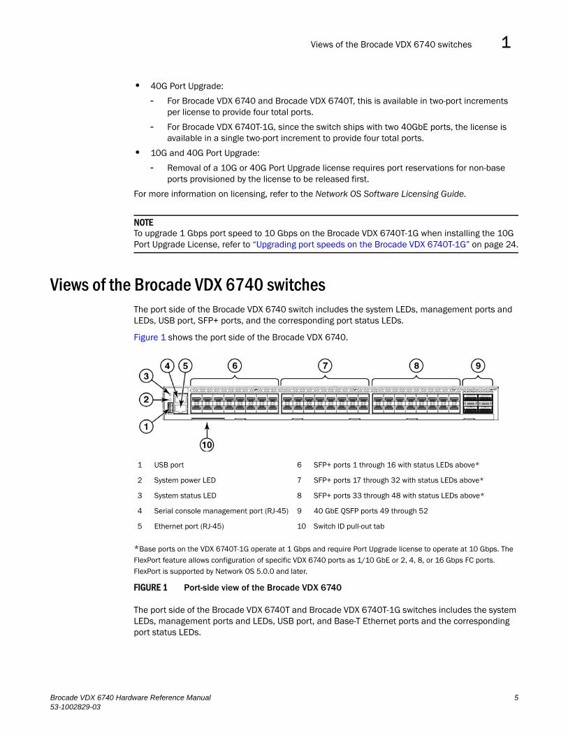
Views of the Brocade VDX 6740 switchesThe port side of the Brocade VDX 6740 switch includes the system LEDs, management ports and LEDs, USB port, SFP+ ports, and the corresponding port status LEDs.
Figure 1 shows the port side of the Brocade VDX 6740.
*Base ports on the VDX 6740T-1G operate at 1 Gbps and require Port Upgrade license to operate at 10 Gbps. The FlexPort feature allows configuration of specific VDX 6740 ports as 1/10 GbE or 2, 4, 8, or 16 Gbps FC ports. FlexPort is supported by Network OS 5.0.0 and later.
FIGURE 1 Port-side view of the Brocade VDX 6740
The port side of the Brocade VDX 6740T and Brocade VDX 6740T-1G switches includes the system LEDs, management ports and LEDs, USB port, and Base-T Ethernet ports and the corresponding port status LEDs.
1 USB port 6 SFP+ ports 1 through 16 with status LEDs above*
2 System power LED 7 SFP+ ports 17 through 32 with status LEDs above*
3 System status LED 8 SFP+ ports 33 through 48 with status LEDs above*
4 Serial console management port (RJ-45) 9 40 GbE QSFP ports 49 through 52
5 Ethernet port (RJ-45) 10 Switch ID pull-out tab
Brocade VDX 6740 Hardware Reference Manual 553-1002829-03
Views of the Brocade VDX 6740 switches1
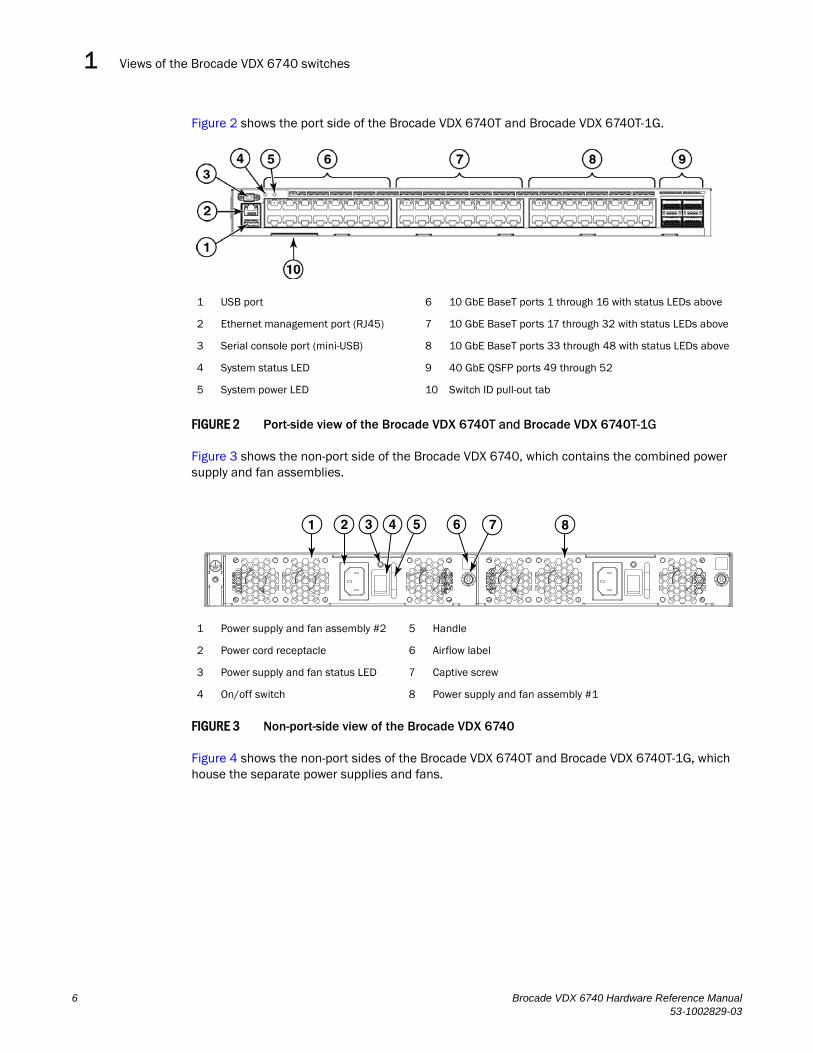
Figure 2 shows the port side of the Brocade VDX 6740T and Brocade VDX 6740T-1G.
FIGURE 2 Port-side view of the Brocade VDX 6740T and Brocade VDX 6740T-1G
Figure 3 shows the non-port side of the Brocade VDX 6740, which contains the combined power supply and fan assemblies.
FIGURE 3 Non-port-side view of the Brocade VDX 6740
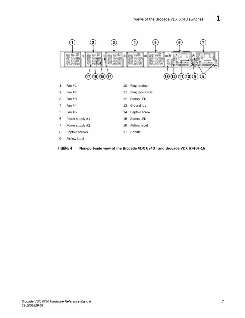
Figure 4 shows the non-port sides of the Brocade VDX 6740T and Brocade VDX 6740T-1G, which house the separate power supplies and fans.
1 USB port 6 10 GbE BaseT ports 1 through 16 with status LEDs above
2 Ethernet management port (RJ45) 7 10 GbE BaseT ports 17 through 32 with status LEDs above
3 Serial console port (mini-USB) 8 10 GbE BaseT ports 33 through 48 with status LEDs above
4 System status LED 9 40 GbE QSFP ports 49 through 52
5 System power LED 10 Switch ID pull-out tab
1 Power supply and fan assembly #2 5 Handle
2 Power cord receptacle 6 Airflow label
3 Power supply and fan status LED 7 Captive screw
4 On/off switch 8 Power supply and fan assembly #1
2 3 71 54 86
6 Brocade VDX 6740 Hardware Reference Manual53-1002829-03
Views of the Brocade VDX 6740 switches 1
FIGURE 4 Non-port-side view of the Brocade VDX 6740T and Brocade VDX 6740T-1G
1 Fan #1 10 Plug retainer
2 Fan #2 11 Plug receptacle
3 Fan #3 12 Status LED
4 Fan #4 13 Ground lug
5 Fan #5 14 Captive screw
6 Power supply #1 15 Status LED
7 Power supply #2 16 Airflow label
8 Captive screws 17 Handle
9 Airflow label
Brocade VDX 6740 Hardware Reference Manual 753-1002829-03

Views of the Brocade VDX 6740 switches1
8 Brocade VDX 6740 Hardware Reference Manual53-1002829-03
Brocade VDX 6740 Hardware Reference Manual53-1002829-03
Chapter
2
Brocade VDX 6740 InstallationIn this chapter•Items included with the Brocade VDX 6740 switches . . . . . . . . . . . . . . . . . . 9
•Installation and safety considerations . . . . . . . . . . . . . . . . . . . . . . . . . . . . . . . 9
•Standalone installation for the Brocade VDX 6740 switches. . . . . . . . . . . . 12
•Rack installation options for the Brocade VDX 6740 switches . . . . . . . . . . 12
•Providing power to the switch . . . . . . . . . . . . . . . . . . . . . . . . . . . . . . . . . . . . . 12
•Verifying operation. . . . . . . . . . . . . . . . . . . . . . . . . . . . . . . . . . . . . . . . . . . . . . 13
Items included with the Brocade VDX 6740 switchesThe following items are included with the standard shipment of a fully-configured Brocade VDX 6740. When you open the Brocade VDX 6740 packaging, verify that the items are included in the package and that no damage has occurred during shipping.
• The Brocade VDX 6740 switch, Brocade VDX 6740T switch, or Brocade VDX 6740T-1G switch
• Transceivers and cables as ordered
• One accessory kit, containing the following items:
- Serial cable with an RJ-45 connector (Brocade VDX 6740) or a mini-USB connector (Brocade VDX 6740T and Brocade VDX 6740T-1G)
- 6 ft. power cords (2)
- Rubber feet, required for setting up the switch as a standalone unit
- 2 GB USB drive
- China RoHS hazardous/toxic substance content chart
- EULA/Read-Me document
- Web pointer card for documentation
Installation and safety considerationsYou can install the Brocade VDX 6740T and Brocade VDX 6740T-1G switches in the following ways:
• As a standalone unit on a flat surface.
• For the Brocade VDX 6740:
- In a four-post EIA rack using a port-side flush mount rack mount kit.
- In a Telco rack using either a port-side flush mount or mid-mount rack kit.
9
Installation and safety considerations2
• For the Brocade VDX 6740T and Brocade VDX 6740T-1G:
- In a four-post EIA rack using a port-side flush mount or a non-port-side flush mount universal fixed-rail rack mount kit.
- In a Telco rack using a port-side flush mount or mid-mount universal rack kit.
NOTEFor the Brocade VDX 6740T and Brocade VDX 6740T-1G, be sure to keep the vents on the sides near the front of the switch are unobstructed.
DANGER
The procedures in this manual are for qualified service personnel.
Electrical considerationsTo install and operate the switch successfully, ensure compliance with the following requirements:
• The primary outlets are correctly wired, protected by a circuit breaker, and grounded in accordance with local electrical codes.
• The supply circuit, line fusing, and wire size are adequate, as specified by the electrical rating on the switch nameplate.
• The power supply standards are met. Refer to Table 12 for more information.
Environmental considerationsFor successful installation and operation of the switch, ensure that the following environmental requirements are met:
• Because the Brocade VDX 6740 switches can be ordered with fans that move air either front to back (exhaust) or back to front (intake), be sure to orient your switch with the airflow pattern of any other devices in the rack. All equipment in the rack should force air in the same direction to avoid intake of exhaust air.
• For the Brocade VDX 6740 - A maximum flow of 43.7 cubic meters/hour (25.7 cubic feet/minute) at the intake vents.
• For the Brocade VDX 6740T and Brocade VDX 6740T-1G - A maximum flow of 83.8 cubic meters/hour (49.3 cubic feet/minute) at the intake vents.
• The ambient air temperature does not exceed 40C (104F) while the switch is operating.
Rack considerationsFor successful installation and operation of the switch in a rack, ensure the following rack requirements are met:
• The rack must be a standard EIA rack.
• The rack space required is one rack unit (1U) 44.45 mm (1.75 in.) high and 482.60 mm (19 in.) wide.
10 Brocade VDX 6740 Hardware Reference Manual53-1002829-03
Installation and safety considerations 2
• The equipment in the rack is grounded through a reliable branch circuit connection and maintains ground at all times. Do not rely on a secondary connection to a branch circuit, such as a power strip.
• Ensure that the rack mounting does not impede airflow or negatively affect temperature requirements, particularly if the switch is installed in a closed or multirack assembly. The Brocade VDX 6740T and Brocade VDX 6740T-1G have airflow openings on either side of the switch toward the front. Ensure that these openings are not obstructed.
• The additional weight of the switch does not exceed the rack’s weight limits or unbalance the rack in any way.
• The rack is secured to ensure stability in case of unexpected movement, such as an earthquake.
Recommendations for cable managementThe minimum radius to which a 50-micron cable can be bent under full tensile load is 5.1 cm (2 in.). For a cable under no tensile load, that minimum is 3.0 cm (1.2 in.).
Cables can be organized and managed in a variety of ways; for example, use cable channels on the sides of the EIA rack or patch panels to reduce the potential for tangling the cables. The following list provides some recommendations for cable management:
NOTEYou should not use tie wraps with optical cables because they are easily overtightened and can damage the optic fibers. Velcro-like wraps are recommended.
• Plan for the rack space required for cable management before installing the switch.
• Leave at least 1 m (3.28 ft) of slack for each port cable. This provides room to remove and replace the switch, allows for inadvertent movement of the rack, and helps prevent the cables from being bent to less than the minimum bend radius.
• For easier maintenance, label the cables and record the devices to which they are connected.
• Keep LEDs visible by routing port cables and other cables away from the LEDs.
Items required for installationThe following items are required for installing, configuring, and connecting the Brocade VDX 6740 switches for use in a network and fabric:
• A workstation with an installed terminal emulator, such as HyperTerminal.
• An unused IP address and corresponding subnet mask and gateway address.
• A serial cable (provided).
• An Ethernet cable.
• (Optional) Access to an FTP server or Brocade-branded USB device for backing up the switch configuration.
• If mounting in the iDataplex IBM 15.5-inch depth rack, the Brocade iDataplex rack mount kit.
Brocade VDX 6740 Hardware Reference Manual 1153-1002829-03
Standalone installation for the Brocade VDX 6740 switches2
Standalone installation for the Brocade VDX 6740 switchesComplete the following steps to install the Brocade VDX 6740 as a standalone unit.
1. Unpack the Brocade VDX 6740 switch and verify the items listed in “Items included with the Brocade VDX 6740 switches” on page 9 are present and undamaged.
2. Apply the adhesive rubber feet. Applying the rubber feet to the switch helps prevent the switch from sliding off the supporting surface.
a. Clean the indentations at each corner of the bottom of the switch to ensure that they are free of dust or other debris that might lessen the adhesion of the feet.
b. With the adhesive side against the chassis, place one rubber foot in each indentation and press into place.
3. Place the switch on a flat, sturdy surface.
4. Provide power to the switch as described in “Providing power to the switch” on page 12.
NOTEDo not connect the switch to the network until the IP address is correctly set. For instructions on how to set the IP address, refer to “Setting the switch IP address” on page 17.
Rack installation options for the Brocade VDX 6740 switchesFollow the installation instructions shipped with the appropriate rack mount kit:
• Mid-Mount Rack Kit (Switch) Installation Procedure (Brocade VDX 6740 only)
• Two-post Flush Mount Installation Procedure (Brocade VDX 6740 only)
• Slim Rail Rack Mount Kit Installation Procedure (Brocade VDX 6740 only)
• 1U-2U Universal 4-Post Rail Mount Kit (Brocade VDX 6740T and Brocade VDX 6740T-1G only)
• 1U-2U Universal 2-Post Rail Mount Kit (Brocade VDX 6740T and Brocade VDX 6740T-1G only)
Providing power to the switchPerform the following steps to provide power to the Brocade VDX 6740 switches.
1. Connect the power cords to both power supplies, and then to power sources on separate circuits to protect against failure. Ensure that the power cords have a minimum service loop of 15.2 cm (6 in.) available and are routed to avoid stress.
2. For the Brocade VDX 6740, flip the switch on each power supply to I.
For the Brocade VDX 6740T and Brocade VDX 6740T-1G, the power supplies power up as soon as they are plugged in.
The power supply LEDs display green. The power LED on the front of the switch turns green as well. The system status LED on the front panel will be amber until POST completes and then it will turn green.
12 Brocade VDX 6740 Hardware Reference Manual53-1002829-03

Verifying operation 2
NOTEPower is supplied to the switch as soon as the first power supply is connected and powered on.
3. After POST is complete, verify that the switch power and status LEDs on the port side of the switch are green.
Verifying operationAfter you have powered the system on and POST is complete, verify that the switch is working properly.
1. Verify that the power supply LEDs are solid green. Refer to Figure 9 and Figure 10 for the location of these LEDs.
2. Verify that the system power LED and the system status LED is solid green. Refer to Figure 7 and Figure 7 and for the specific locations of these LEDs.
3. The port LEDs should be lit during POST activities. When POST is complete, only the LEDs for ports connected to other devices should be green. Refer to Figure 7 and Figure 7 for the specific locations of these LEDs.
Refer to Table 3 for more details on the LED patterns.
Brocade VDX 6740 Hardware Reference Manual 1353-1002829-03

Verifying operation2
14 Brocade VDX 6740 Hardware Reference Manual53-1002829-03
Brocade VDX 6740 Hardware Reference Manual53-1002829-03
Chapter
3
Brocade VDX 6740 ConfigurationIn this chapter•Configuration for the Brocade VDX 6740 switches . . . . . . . . . . . . . . . . . . . . 15
•Creating a serial connection . . . . . . . . . . . . . . . . . . . . . . . . . . . . . . . . . . . . . . 16
•Permanent password assignment . . . . . . . . . . . . . . . . . . . . . . . . . . . . . . . . . 17
•Setting the switch IP address . . . . . . . . . . . . . . . . . . . . . . . . . . . . . . . . . . . . . 17
•Changing the RBridge ID. . . . . . . . . . . . . . . . . . . . . . . . . . . . . . . . . . . . . . . . . 19
•Changing the VCS ID . . . . . . . . . . . . . . . . . . . . . . . . . . . . . . . . . . . . . . . . . . . . 19
•Date and time on the Brocade VDX 6740 . . . . . . . . . . . . . . . . . . . . . . . . . . . 20
•Network device connections. . . . . . . . . . . . . . . . . . . . . . . . . . . . . . . . . . . . . . 22
•Brocade inter-switch link trunks . . . . . . . . . . . . . . . . . . . . . . . . . . . . . . . . . . . 23
•Upgrading port speeds on the Brocade VDX 6740T-1G . . . . . . . . . . . . . . . . 24
•FlexPort configuration . . . . . . . . . . . . . . . . . . . . . . . . . . . . . . . . . . . . . . . . . . . 25
Configuration for the Brocade VDX 6740 switchesThe Brocade VDX 6740 switches can be configured in VCS™ mode, which is enabled by default.
In VCS mode, the switch is part of an Ethernet fabric involving two or more VCS-enabled switches. VCS technology embodies the concepts of distributed intelligence and logical chassis. Distributed intelligence means that all configuration and destination information is automatically distributed to each member switch in the fabric. Distributed intelligence has three major characteristics:
• The fabric is self-forming. When two VCS-enabled switches are connected, the fabric is automatically created and the switches discover the common fabric configuration.
• The fabric is masterless. No single switch stores configuration information or controls fabric operations. Any switch can fail or be removed without causing disruptive fabric downtime or delayed traffic.
• The fabric is aware of all members, devices, and Virtual Machines (VMs). Automatic Migration of Port Profiles (AMPP) supports VM migration to another physical server. If the VM moves, it is automatically reconnected to all of its original resources.
Logical chassis means that the entire VCS fabric appears and can be managed as a single Layer 2 switch. There are three major characteristics to logical chassis:
• Each physical switch in the fabric can be managed as if it were a blade in a chassis. When a VCS-enabled switch is connected to the fabric, it inherits the configuration of the fabric and the new ports become available immediately.
• You can manage the entire fabric from any switch.
• You can manage the edge switches in the fabric as if they were a single switch.
15
Creating a serial connection3
Creating a serial connectionYou perform all configuration tasks in this guide using a serial connection from a workstation or terminal to the switch.
Complete the following steps to create a serial connection to the switch.
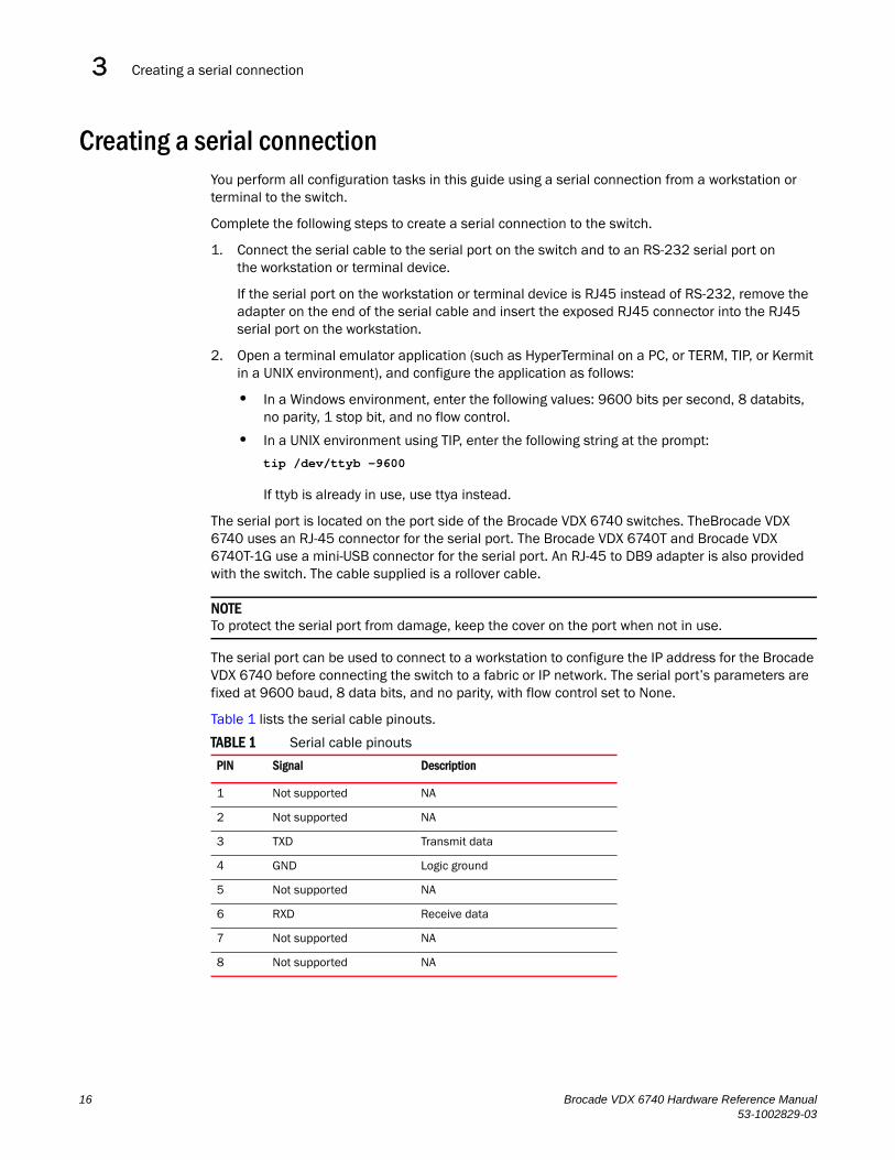
1. Connect the serial cable to the serial port on the switch and to an RS-232 serial port on the workstation or terminal device.
If the serial port on the workstation or terminal device is RJ45 instead of RS-232, remove the adapter on the end of the serial cable and insert the exposed RJ45 connector into the RJ45 serial port on the workstation.
2. Open a terminal emulator application (such as HyperTerminal on a PC, or TERM, TIP, or Kermit in a UNIX environment), and configure the application as follows:
• In a Windows environment, enter the following values: 9600 bits per second, 8 databits, no parity, 1 stop bit, and no flow control.
• In a UNIX environment using TIP, enter the following string at the prompt:
tip /dev/ttyb -9600
If ttyb is already in use, use ttya instead.
The serial port is located on the port side of the Brocade VDX 6740 switches. TheBrocade VDX 6740 uses an RJ-45 connector for the serial port. The Brocade VDX 6740T and Brocade VDX 6740T-1G use a mini-USB connector for the serial port. An RJ-45 to DB9 adapter is also provided with the switch. The cable supplied is a rollover cable.
NOTETo protect the serial port from damage, keep the cover on the port when not in use.
The serial port can be used to connect to a workstation to configure the IP address for the Brocade VDX 6740 before connecting the switch to a fabric or IP network. The serial port’s parameters are fixed at 9600 baud, 8 data bits, and no parity, with flow control set to None.
Table 1 lists the serial cable pinouts.
TABLE 1 Serial cable pinouts
PIN Signal Description
1 Not supported NA
2 Not supported NA
3 TXD Transmit data
4 GND Logic ground
5 Not supported NA
6 RXD Receive data
7 Not supported NA
8 Not supported NA
16 Brocade VDX 6740 Hardware Reference Manual53-1002829-03
Permanent password assignment 3
Permanent password assignmentWhen you log in for the first time, Brocade recommends that you change the passwords for the default accounts.
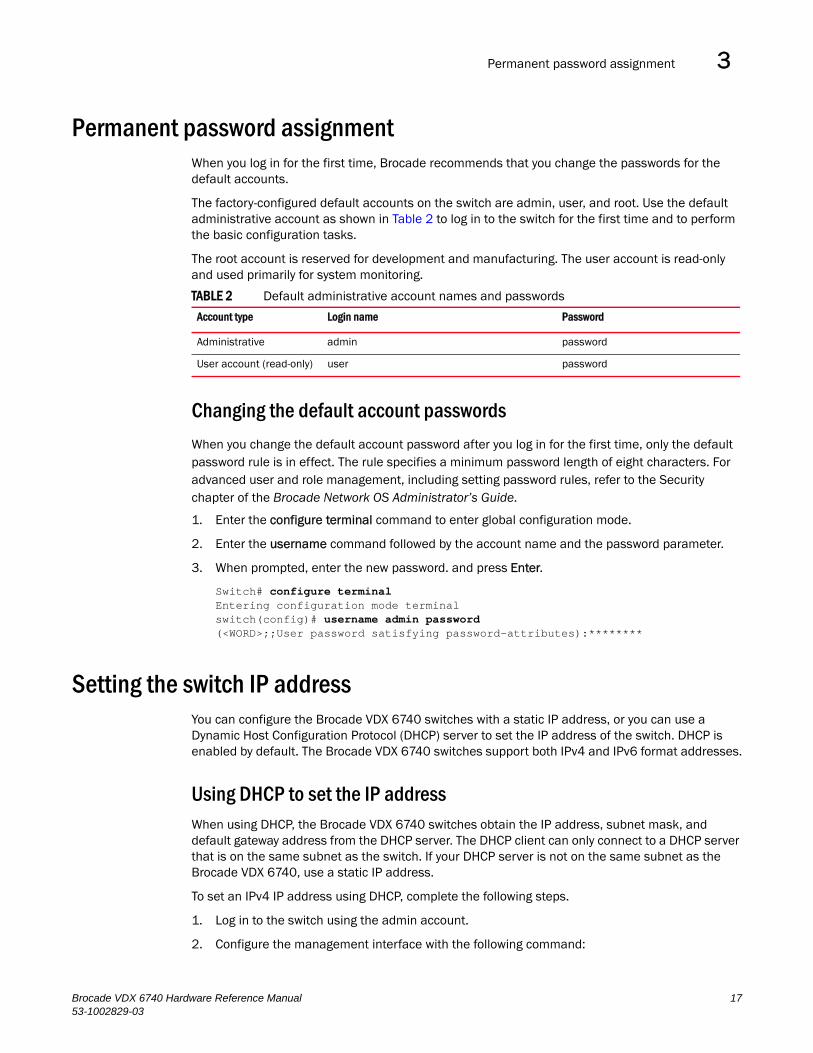
The factory-configured default accounts on the switch are admin, user, and root. Use the default administrative account as shown in Table 2 to log in to the switch for the first time and to perform the basic configuration tasks.
The root account is reserved for development and manufacturing. The user account is read-only and used primarily for system monitoring.
Changing the default account passwords
When you change the default account password after you log in for the first time, only the default password rule is in effect. The rule specifies a minimum password length of eight characters. For advanced user and role management, including setting password rules, refer to the Security chapter of the Brocade Network OS Administrator’s Guide.
1. Enter the configure terminal command to enter global configuration mode.
2. Enter the username command followed by the account name and the password parameter.
3. When prompted, enter the new password. and press Enter.
Switch# configure terminalEntering configuration mode terminalswitch(config)# username admin password(<WORD>;;User password satisfying password-attributes):********
Setting the switch IP addressYou can configure the Brocade VDX 6740 switches with a static IP address, or you can use a Dynamic Host Configuration Protocol (DHCP) server to set the IP address of the switch. DHCP is enabled by default. The Brocade VDX 6740 switches support both IPv4 and IPv6 format addresses.
Using DHCP to set the IP addressWhen using DHCP, the Brocade VDX 6740 switches obtain the IP address, subnet mask, and default gateway address from the DHCP server. The DHCP client can only connect to a DHCP server that is on the same subnet as the switch. If your DHCP server is not on the same subnet as the Brocade VDX 6740, use a static IP address.
To set an IPv4 IP address using DHCP, complete the following steps.
1. Log in to the switch using the admin account.
2. Configure the management interface with the following command:
TABLE 2 Default administrative account names and passwords
Account type Login name Password
Administrative admin password
User account (read-only) user password
Brocade VDX 6740 Hardware Reference Manual 1753-1002829-03
Setting the switch IP address3
switch(config)# interface Management 1/0
3. Configure the IP address using the following command:
switch(config-Management-1/0)# ip address dhcp
Setting a static IP addressComplete the following steps to set a static IP address.
1. Log in to the switch using the default password (the default password is password).
2. Use the ip address command to set the Ethernet IP address.
If you are going to use an IPv4 IP address, enter the IP address in dotted decimal notation. You should also disable DHCP and enter a gateway address as well.
switch(config)# interface Management 1/0switch(config-Management-1/0)# no ip address dhcpswitch(config-Management-1/0)# ip address 10.24.85.81/20
To set up a default gateway, add an ip route in rbridge mode.
switch(config-rbridge-id-10)# ip route 0.0.0.0/0 10.24.80.1switch# copy running-config startup-config
If you are going to use an IPv6 address, enter the network information in semicolon-separated notation as prompted after the ipv6 address operand.
switch(config)# interface Management 1/0switch(config-Management-1/0)# no ip address dhcpswitch(config-Management-1/0)# ipv6 address \fd00;60;69bc;832;e61f;13ff;fe67;4b94/64
3. To display the configuration, use the show running-config interface Management command.
switch# show running-config interface Management 1/0interface Management 1/0no ip address dhcpip address 10.24.85.81/20ipv6 address fd00;60;69bc;832;e61f;13ff;fe67;4b94/64no ipv6 address autoconfig
!
Stateless IPv6 autoconfigurationIPv6 allows assignment of multiple IP addresses to each network interface. Each interface is configured with a link local address in almost all cases, but this address is only accessible from other hosts on the same network. To provide for wider accessibility, interfaces are typically configured with at least one additional global scope IPv6 address. IPv6 autoconfiguration allows more IPv6 addresses, the number of which is dependent on the number of routers serving the local network and the number of prefixes they advertise.
When IPv6 autoconfiguration is enabled, the platform will engage in stateless IPv6 autoconfiguration. When IPv6 autoconfiguration is disabled, the platform will relinquish usage of any autoconfigured IPv6 addresses that it may have acquired while IPv6 autoconfiguration was enabled. This same enabled or disabled state also enables or disables the usage of a link local address for each managed entity (though a link local address will continue to be generated for each switch) because those link local addresses are required for router discovery.
18 Brocade VDX 6740 Hardware Reference Manual53-1002829-03
Changing the RBridge ID 3
The enabled or disabled state of autoconfiguration does not affect any static IPv6 addresses that may have been configured. Stateless IPv6 autoconfiguration and static IPv6 addresses can coexist.
Setting stateless IPv6 autoconfigurationTo configure stateless IPv6 autoconfiguration, complete the following steps.
1. Issue the configure terminal command to enter global configuration mode.
2. Take the appropriate action based on whether you want to enable or disable IPv6 autoconfiguration:
• Enter the ipv6 address autoconfig command to enable IPv6 autoconfiguration for all managed entities on the target platform.
• Enter the no ipv6 address autoconfig command to disable IPv6 autoconfiguration for all managed entities on the target platform.
Changing the RBridge IDIf you are going to have more than one switch in a fabric, each switch must have a unique RBridge ID. The default RBridge ID for any Brocade VDX 6740 is 1. Use the vcs rbridge-id [rbridge-id] command to change the default RBridge ID. You should be in privileged EXEC mode to run the command. If you have made any other configuration changes you want to persist, be sure to save your running configuration to the startup configuration before running the vcs rbridge-id command as this command reboots the switch.
Enter the vcs rbridge-id [rbridge-id] command.
switch# vcs rbridge-id 2This operation will change the configuration to default and reboot the switch. Do you want to continue? [y/n]:y
When the confirmation question appears, answer Y.
The reply to the command will include a line about the setting of the RBridge ID.
Successfully set rbridge-id.
Changing the VCS IDIf you are going to have more than one VCS fabric, each fabric must have a unique VCS ID. The default VCS ID for any VCS fabric is 1. Use the vcs vcs-id [ID] command to change the default VCS ID. You should be in privileged EXEC mode to run the command. If you have made any other configuration changes you want to persist, be sure to save your running configuration to the startup configuration before running the vcs vcs-id command as this command reboots the switch.
Enter the vcs vcs-id [ID] command.
switch# vcs vcs-id 2This operation will change the configuration to default and reboot the switch. Do you want to continue? [y/n]:y
When the confirmation question appears, answer Y.
Brocade VDX 6740 Hardware Reference Manual 1953-1002829-03
Date and time on the Brocade VDX 67403
The reply to the command will include a line about the setting of the VCS ID.
Successfully set vcs-id.
Date and time on the Brocade VDX 6740The Brocade VDX 6740 switches maintain the current date and time inside a battery-backed real-time clock (RTC) circuit. Date and time are used for logging events. Switch operation does not depend on the date and time; a Brocade VDX 6740 switch with an incorrect date and time value functions properly. Because the date and time are used for logging, error detection, and troubleshooting, you should set them correctly.
Time zonesYou can set the time zone for a switch by using the clock TimeZone command. The time zone setting has the following characteristics:
• The clock TimeZone setting automatically adjusts for Daylight Savings Time.
• Changing the time zone on a switch updates the local time zone setup and is reflected in local time calculations.
• By default, all switches are in the Greenwich Mean Time (GMT) time zone (0,0). If all switches in a fabric are in one time zone, it is possible for you to keep the time zone setup at the default setting.
• System services that have already started will reflect the time zone changes only after the next reboot.
• Time zone settings persist across failover for high availability.
• Time zone settings are not affected by Network Time Protocol (NTP) server synchronization.
The following regions are supported: Africa, America, Antarctica, Asia, Atlantic, Australia, Europe, Indian, and Pacific. One of these, along with a city name, establishes the time zone.
Time synchronizationTo keep the time in your network current, it is recommended that the principal switch has its time synchronized with at least one external NTP server. The other switches in the fabric will automatically take their time from the principal switch.
All switches in the fabric maintain the current clock server value in nonvolatile memory. By default, this value is the local clock server of the principal switch. Changes to the clock server value on the principal switch are propagated to all switches in the fabric.
When a new switch enters the fabric, the time server daemon of the principal switch sends out the addresses of all existing clock servers and the time to the new switch.
The ntp server command accepts multiple server addresses in IPv4 format. When multiple NTP server addresses are passed, ntp server sets the first obtainable address as the active NTP server. If there are no reachable time servers, then the local switch time is the default time.
20 Brocade VDX 6740 Hardware Reference Manual53-1002829-03

Date and time on the Brocade VDX 6740 3
Synchronizing local time using NTPPerform the following steps to synchronize the local time using NTP.
1. Log in to the switch using the default password (the default password is password).
2. Enter the ntp server “IPv4 address” command, where IPv4 address is the IP address of the first NTP server in IPv4 format, which the switch must be able to access. The IPv4 address variable is optional. By default, this value is LOCL, which uses the local clock of the principal switch as the clock server.
switch:admin> ntp server "132.163.135.131"
To display the NTP server IP address, use the show ntp status [switchid switchid | all] command.
switch:admin> show ntp status switchid 132.163.135.131
The request is for the local switch unless a switch ID is specified. Specify the all parameter to send the request to all switches in the cluster.
If you need to remove an NTP server, use the no form of the ntp server command.
switch:admin> no ntp server "132.163.135.131"
Setting the clock (date and time) manuallyYou should set the clock only if there are no NTP servers configured. Time synchronization from NTP servers overrides the local clock. Date values are limited to between January 1, 1970 and January 19, 2038.
1. Log in to the switch using the default password (the default password is password).
2. Enter the clock set year-month-dayThours:minutes:seconds command.
The following example sets the clock to March 17, 2010, 15 minutes past noon:
switch:admin > clock set 2010-03-17T12:15:00
3. To show the clock and time zone settings, use the show clock [switchid switchid | all] command.
switch:admin > show clock switchid 1
Setting time zonesYou must perform this procedure on all switches for which the time zone must be set. However, you only need to set the time zone once on each switch, because the value is written to nonvolatile memory. While not necessary for switch operation, setting a time zone is part of ensuring accurate logging and audit tracking. Time zone changes take effect after a reboot.
Use the clock TimeZone command to set the time zone.
1. Connect to the switch and log in using an account assigned to the admin role.
2. Enter the clock TimeZone region/city command.
The following example changes the time zone to US/Pacific Standard Time:
switch:admin > clock timezone America/Los_Angeles
Brocade VDX 6740 Hardware Reference Manual 2153-1002829-03
Network device connections3
3. Reboot the switch.
Network device connectionsPlease refer to Table 17 for a listing of supported cables for the Brocade VDX 6740 switches.
NOTEBefore plugging a cable to any port, be sure to discharge any static charge stored on the cable by touching the electrical contacts to a grounded surface.
Ethernet or Fast Ethernet hubsFor copper connections to Ethernet hubs, a 1000Base-T switch, or another Brocade device, a crossover cable is required. If the hub is equipped with an uplink port, it requires a straight-through cable instead of a crossover cable.
NOTEThe 802.3ab standard (automatic MDI or MDIX detection) calls for automatic negotiation of the connection between two 1000Base-T ports. Therefore, a crossover cable may not be required; a straight-through cable may work as well.
Workstations, servers, or routersStraight-through UTP cabling is required for direct UTP attachment to workstations, servers, or routers using network interface cards (NICs).
Fiber cabling is required for direct attachment to Gigabit NICs or switches and routers through fiber ports.
Network deviceFor direct attachment from the Brocade device to a Gigabit NIC, switch, or router, you can use either a fiber cabling with an LC connector or a copper cable with an RJ-45 connector.
Testing connectivityAfter you install the network cables, you can test network connectivity to other devices by observing the LEDs related to network connection and performing trace routes. Refer to Table 3 on page 30 for a description of the port states.
22 Brocade VDX 6740 Hardware Reference Manual53-1002829-03
Brocade inter-switch link trunks 3
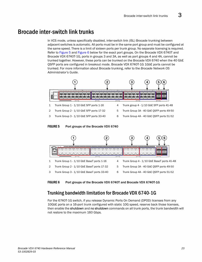
Brocade inter-switch link trunksIn VCS mode, unless specifically disabled, inter-switch link (ISL) Brocade trunking between adjacent switches is automatic. All ports must be in the same port group and must be configured at the same speed. There is a limit of sixteen ports per trunk group. No separate licensing is required. Refer to Figure 5 and Figure 6 below for the exact port groups. On the Brocade VDX 6740T and Brocade VDX 6740T-1G, ports in groups 3 and 3A, as well as port groups 4 and 4A, cannot be trunked together. However, these ports can be trunked on the Brocade VDX 6740 when the 40 GbE QSFP ports are configured in breakout mode. Brocade VDX 6740T-1G 1GbE ports cannot be trunked. For more information about Brocade trunking, refer to the Brocade Network OS Administrator’s Guide.
FIGURE 5 Port groups of the Brocade VDX 6740
FIGURE 6 Port groups of the Brocade VDX 6740T and Brocade VDX 6740T-1G
Trunking bandwidth limitation for Brocade VDX 6740-1GFor the 6740T-1G switch, if you release Dynamic Ports On Demand (DPOD) licenses from any 10GbE ports on a 16-port trunk configured with static 10G speed, reserve back those licenses, then enable the shutdown and no shutdown commands on all trunk ports, the trunk bandwidth will not restore to the maximum 160 Gbps.
1 Trunk Group 1 - 1/10 GbE SFP ports 1-16 4 Trunk group 4 - 1/10 GbE SFP ports 41-48
2 Trunk Group 2 - 1/10 GbE SFP ports 17-32 5 Trunk Group 3A - 40 GbE QSFP ports 49-50
3 Trunk Group 3 - 1/10 GbE SFP ports 33-40 6 Trunk Group 4A - 40 GbE QSFP ports 51-52
1 Trunk Group 1 - 1/10 GbE BaseT ports 1-16 4 Trunk Group 4 - 1/10 GbE BaseT ports 41-48
2 Trunk Group 2 - 1/10 GbE BaseT ports 17-32 5 Trunk Group 3A - 40 GbE QSFP ports 49-50
3 Trunk Group 3 - 1/10 GbE BaseT ports 33-40 6 Trunk Group 4A - 40 GbE QSFP ports 51-52
Brocade VDX 6740 Hardware Reference Manual 2353-1002829-03
Upgrading port speeds on the Brocade VDX 6740T-1G3
Upgrading port speeds on the Brocade VDX 6740T-1GUsing the 10G Port Upgrade License, you can enable RJ45 ports operating at 1 Gbps on the Brocade VDX 6740T-1G switch to also operate at 10 Gbps. The license is applied in increments of 16 ports. To upgrade the ports, use the following procedure.
1. Install the PORT_10G_UPGRADE license. Use the following instructions in the Administering Licenses chapter of the Network OS Administrator’s Guide:
• Displaying the switch ID
• Obtaining the license key
• Installing a license
2. Enter the show dpod command to verify the allowed reservation pool size and to determine 10G ports that are assigned to a 10G Port Upgrade license already.
switch# show dpod
3. Enter the configure terminal command to access global configuration mode
switch# configure terminal
4. Enter the shutdown command for the interface if not already in shutdown state.
switch(config)# interface gigabitethernet 1/0/1switch(conf-if-gi-1/0/1)# shutdown
5. Enter the dpod command while in global configuration mode to reserve a license assignment for the port from the license pool.
switch(config)dpod 1/0/1 reserve
NOTETo remove a license assignment for a port, use release instead of reserve.
6. Perform one of the following steps:
• Configure interface speed to 10000 using the speed command.
switch(config)# interface tengigabitethernet 1/0/1switch(conf-if-int-1/0/1)# speed 10000
NOTEThis operation may fail as a result of limited available reservations.
• Configure the interface speed to auto to allow dynamic link speed selection up to 10 Gbps.
switch(config)# interface tengigabitethernet 1/0/1switch(conf-if-int-1/0/1)# speed auto
7. Enable the 10G interface using the no shutdown command.
switch(config)# interface tengigabitethernet 1/0/1switch(conf-if-te-1/0/1)# no shutdown
24 Brocade VDX 6740 Hardware Reference Manual53-1002829-03

FlexPort configuration 3
FlexPort configurationFor details on this feature, including configuration procedures, refer to the Brocade Network OS Layer 2 Switching Configuration Guide. FlexPort is supported by Network OS 5.0.0 and later.
Brocade VDX 6740 Hardware Reference Manual 2553-1002829-03
FlexPort configuration3
26 Brocade VDX 6740 Hardware Reference Manual53-1002829-03
Brocade VDX 6740 Hardware Reference Manual53-1002829-03
Chapter
4
Brocade VDX 6740 OperationIn this chapter•LED activity interpretation. . . . . . . . . . . . . . . . . . . . . . . . . . . . . . . . . . . . . . . . 27
•POST and boot specifications . . . . . . . . . . . . . . . . . . . . . . . . . . . . . . . . . . . . . 33
•Interpreting POST results . . . . . . . . . . . . . . . . . . . . . . . . . . . . . . . . . . . . . . . . 34
•Powering off the Brocade VDX 6740 switches . . . . . . . . . . . . . . . . . . . . . . . 35
•Brocade VDX 6740 maintenance . . . . . . . . . . . . . . . . . . . . . . . . . . . . . . . . . . 35
•Brocade VDX 6740 management. . . . . . . . . . . . . . . . . . . . . . . . . . . . . . . . . . 38
LED activity interpretationSystem activity and status can be determined through the activity of the LEDs on the switch.
There are three possible LED states: off (no light), a steady light, and a flashing light. Flashing lights may be slow, fast, or flickering. The LED colors are either green or amber. Refer to Table 3 on page 30 and Table 4 on page 32 for details on LED behavior.
Sometimes, the LEDs flash either of the colors during boot, POST, or other diagnostic tests. This is normal; it does not indicate a problem unless the LEDs do not indicate a healthy state after all boot processes and diagnostic tests are complete.
Brocade VDX 6740 LEDsThe Brocade VDX 6740 switches have the following LEDs:
• One bicolor system status LED (green and amber) on the port side.
• One power status LED (green) on the port side.
• Two Ethernet management port LEDs (green) for the Ethernet management port. The two LEDs show the status of the port link and the port activity.
• One triangle-shaped bicolor port status LED (green and amber) for each 10 GbE port on the switch. These LEDs are arrayed above each vertical pair of ports on the Brocade VDX 6740. The left LED corresponds to the upper port of the pair and the right LED corresponds to the lower port.
• One triangle-shaped bicolor port status LED (green and amber) for each 40 GbE port on the switch. These LEDs are arrayed between each vertical pair of 40 GbE ports on the Brocade VDX 6740 switches. The left LED corresponds to the upper port of the pair and the right LED corresponds to the lower port.
• One power supply and fan assembly LED (green) above the AC power switch on each combined power supply and fan assembly on the non-port side of the switch on the Brocade VDX 6740.
27
LED activity interpretation4
• One power supply LED (green) to the left of the AC power plug on each power supply on the non-port side of the switch on the Brocade VDX 6740T and Brocade VDX 6740T-1G.
• One bicolor fan status LED (green and amber) on each fan assembly on the non-port side of the switch on the Brocade VDX 6740T and Brocade VDX 6740T-1G.
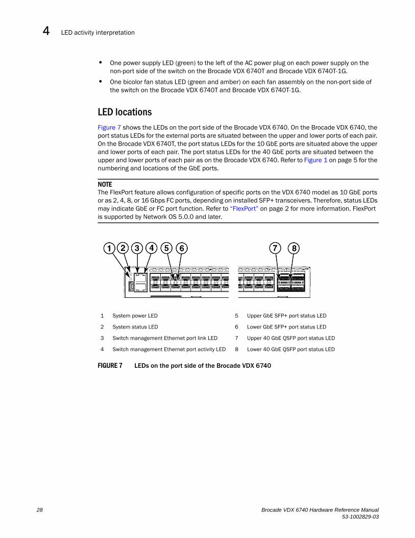
LED locationsFigure 7 shows the LEDs on the port side of the Brocade VDX 6740. On the Brocade VDX 6740, the port status LEDs for the external ports are situated between the upper and lower ports of each pair. On the Brocade VDX 6740T, the port status LEDs for the 10 GbE ports are situated above the upper and lower ports of each pair. The port status LEDs for the 40 GbE ports are situated between the upper and lower ports of each pair as on the Brocade VDX 6740. Refer to Figure 1 on page 5 for the numbering and locations of the GbE ports.
NOTEThe FlexPort feature allows configuration of specific ports on the VDX 6740 model as 10 GbE ports or as 2, 4, 8, or 16 Gbps FC ports, depending on installed SFP+ transceivers. Therefore, status LEDs may indicate GbE or FC port function. Refer to “FlexPort” on page 2 for more information. FlexPort is supported by Network OS 5.0.0 and later.
FIGURE 7 LEDs on the port side of the Brocade VDX 6740
1 System power LED 5 Upper GbE SFP+ port status LED
2 System status LED 6 Lower GbE SFP+ port status LED
3 Switch management Ethernet port link LED 7 Upper 40 GbE QSFP port status LED
4 Switch management Ethernet port activity LED 8 Lower 40 GbE QSFP port status LED
28 Brocade VDX 6740 Hardware Reference Manual53-1002829-03
LED activity interpretation 4
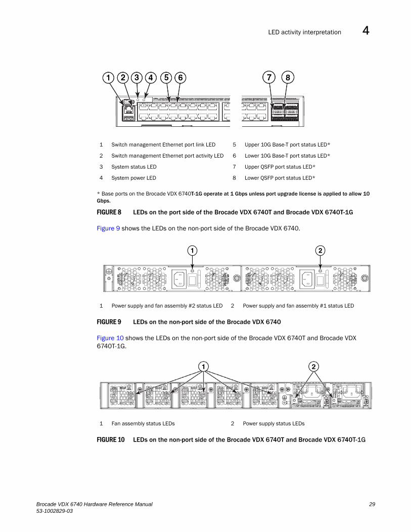
* Base ports on the Brocade VDX 6740T-1G operate at 1 Gbps unless port upgrade license is applied to allow 10 Gbps.
FIGURE 8 LEDs on the port side of the Brocade VDX 6740T and Brocade VDX 6740T-1G
Figure 9 shows the LEDs on the non-port side of the Brocade VDX 6740.
FIGURE 9 LEDs on the non-port side of the Brocade VDX 6740
Figure 10 shows the LEDs on the non-port side of the Brocade VDX 6740T and Brocade VDX 6740T-1G.
FIGURE 10 LEDs on the non-port side of the Brocade VDX 6740T and Brocade VDX 6740T-1G
1 Switch management Ethernet port link LED 5 Upper 10G Base-T port status LED*
2 Switch management Ethernet port activity LED 6 Lower 10G Base-T port status LED*
3 System status LED 7 Upper QSFP port status LED*
4 System power LED 8 Lower QSFP port status LED*
1 Power supply and fan assembly #2 status LED 2 Power supply and fan assembly #1 status LED
1 Fan assembly status LEDs 2 Power supply status LEDs
1 2
Brocade VDX 6740 Hardware Reference Manual 2953-1002829-03
LED activity interpretation4
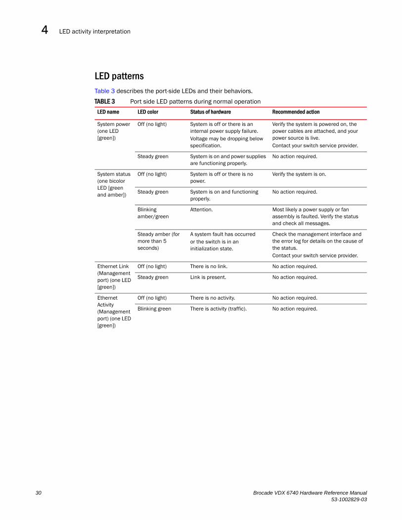
LED patternsTable 3 describes the port-side LEDs and their behaviors.
TABLE 3 Port side LED patterns during normal operation
LED name LED color Status of hardware Recommended action
System power (one LED [green])
Off (no light) System is off or there is an internal power supply failure.Voltage may be dropping below specification.
Verify the system is powered on, the power cables are attached, and your power source is live.Contact your switch service provider.
Steady green System is on and power supplies are functioning properly.
No action required.
System status (one bicolor LED [green and amber])
Off (no light) System is off or there is no power.
Verify the system is on.
Steady green System is on and functioning properly.
No action required.
Blinking amber/green
Attention. Most likely a power supply or fan assembly is faulted. Verify the status and check all messages.
Steady amber (for more than 5 seconds)
A system fault has occurredor the switch is in an initialization state.
Check the management interface and the error log for details on the cause of the status. Contact your switch service provider.
Ethernet Link (Management port) (one LED [green])
Off (no light) There is no link. No action required.
Steady green Link is present. No action required.
Ethernet Activity (Management port) (one LED [green])
Off (no light) There is no activity. No action required.
Blinking green There is activity (traffic). No action required.
30 Brocade VDX 6740 Hardware Reference Manual53-1002829-03
LED activity interpretation 4
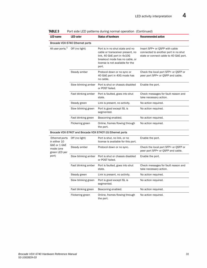
Brocade VDX 6740 Ethernet ports
All user ports.1 Off (no light) Port is in no shut state and no cable or transceiver present, no link, 40 GbE port in 4x10G breakout mode has no cable, or license is not available for the port.
Insert SFP+ or QSFP with cable connected to another port in no shut state or connect cable to 40 GbE port.
Steady amber Protocol down or no sync or40 GbE port in 40G mode has no cable.
Check the local port SFP+ or QSFP or peer port SFP+ or QSFP and cable.
Slow blinking amber Port is shut or chassis disabled or POST failed.
Enable the port.
Fast blinking amber Port is faulted, goes into shut state.
Check messages for fault reason and take necessary action.
Steady green Link is present, no activity. No action required.
Slow blinking green Port is good except ISL is segmented.
No action required.
Fast blinking green Beaconing enabled. No action required.
Flickering green Online, frames flowing through the port.
No action required.
Brocade VDX 6740T and Brocade VDX 6740T-1G Ethernet ports
Ethernet ports in either 10 GbE or 1 GbE mode (one green LED per port)
Off (no light) Port is shut, no link, or no license is available for this port.
Enable the port.
Steady amber Protocol down or no sync. Check the local port SFP+ or QSFP or peer port SFP+ or QSFP and cable.
Slow blinking amber Port is shut or chassis disabled or POST failed.
Enable the port.
Fast blinking amber Port is faulted, goes into shut state.
Check messages for fault reason and take necessary action.
Steady green Link is present, no activity. No action required.
Slow blinking green Port is good except ISL is segmented.
No action required.
Fast blinking green Beaconing enabled. No action required.
Flickering green Online, frames flowing through the port.
No action required.
TABLE 3 Port side LED patterns during normal operation (Continued)
LED name LED color Status of hardware Recommended action
Brocade VDX 6740 Hardware Reference Manual 3153-1002829-03
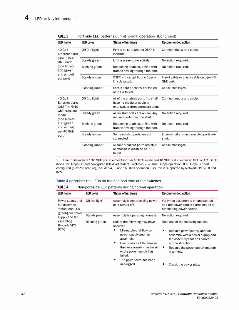
LED activity interpretation4
Table 4 describes the LEDs on the non-port side of the switches.
40 GbE Ethernet ports (QSFP) in 40 GbE mode(one bicolor LED [green and amber] per port)
Off (no light) Port is no shut and no QSFP is inserted.
Connect media and cable.
Steady green Link is present, no activity. No action required.
Blinking green Beaconing enabled, online with frames flowing through the port.
No action required.
Steady amber QSFP is inserted but no fiber or link detected.
Insert cable or check cable on peer 40 GbE port.
Flashing amber Port is shut or chassis disabled or POST failed
Check messages.
40 GbE Ethernet ports (QSFP) in 4x10 GbE breakout mode(one bicolor LED [green and amber] per 40 GbE port)
Off (no light) All of the enabled ports (no shut) have no media or cable or one, two, or three ports are shut.
Connect media and cable.
Steady green All no shut ports are online. Any unused ports must be shut.
No action required.
Blinking green Beaconing enabled, online with frames flowing through the port.
No action required.
Steady amber Some no shut ports are not connected.
Ensure that any unconnected ports are shut.
Flashing amber All four breakout ports are shut or chassis is disabled or POST failed.
Check messages.
1. User ports include 1/10 GbE port in either 1 GbE or 10 GbE mode and 40 GbE port in either 40 GbE or 4x10 GbE mode. If 8 Gbps FC port configured (FlexPort feature), includes 2, 4, and 8 Gbps operation. If 16 Gbps FC port configured (FlexPort feature), includes 4, 8, and 16 Gbps operation. FlexPort is supported by Network OS 5.0.0 and later.
TABLE 4 Non-port-side LED patterns during normal operation
LED name LED color Status of hardware Recommended action
Power supply and fan assembly status (one LED [green] per power supply and fan assembly)Brocade VDX 6740
Off (no light) Assembly is not receiving power or is turned off.
Verify the assembly is on and seated and the power cord is connected to a functioning power source.
Steady green Assembly is operating normally. No action required.
Blinking green One of the following may have occurred:• Mismatched airflow on
power supply and fan assembly.
• One or more of the fans in the fan assembly has failed or the power supply has failed.
• The power cord has been unplugged.
Take one of the following actions:
• Replace power supply and fan assembly with a power supply and fan assembly that has correct airflow direction.
• Replace the power supply and fan assembly.
• Check the power plug.
TABLE 3 Port side LED patterns during normal operation (Continued)
LED name LED color Status of hardware Recommended action
32 Brocade VDX 6740 Hardware Reference Manual53-1002829-03
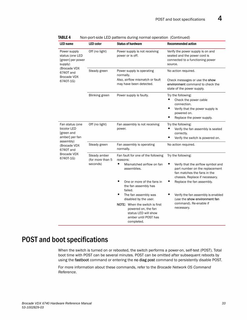
POST and boot specifications 4
POST and boot specificationsWhen the switch is turned on or rebooted, the switch performs a power-on, self-test (POST). Total boot time with POST can be several minutes. POST can be omitted after subsequent reboots by using the fastboot command or entering the no diag post command to persistently disable POST.
For more information about these commands, refer to the Brocade Network OS Command Reference.
Power supply status (one LED [green] per power supply) (Brocade VDX 6740T and Brocade VDX 6740T-1G)
Off (no light) Power supply is not receiving power or is off.
Verify the power supply is on and seated and the power cord is connected to a functioning power source.
Steady green Power supply is operating normally.Also, airflow mismatch or fault may have been detected.
No action required.
Check messages or use the show environment command to check the state of the power supply.
Blinking green Power supply is faulty. Try the following: • Check the power cable
connection.• Verify that the power supply is
powered on.• Replace the power supply.
Fan status (one bicolor LED [green and amber] per fan assembly) (Brocade VDX 6740T and Brocade VDX 6740T-1G)
Off (no light) Fan assembly is not receiving power.
Try the following: • Verify the fan assembly is seated
correctly.• Verify the switch is powered on.
Steady green Fan assembly is operating normally.
No action required.
Steady amber (for more than 5 seconds)
Fan fault for one of the following reasons: • Mismatched airflow on fan
assemblies.
• One or more of the fans in the fan assembly has failed.
• The fan assembly was disabled by the user.
NOTE: When the switch is first powered on, the fan status LED will show amber until POST has completed.
Try the following:
• Verify that the airflow symbol and part number on the replacement fan matches the fans in the chassis. Replace if necessary.
• Replace the fan assembly.
• Verify the fan assembly is enabled (use the show environment fan command). Re-enable if necessary.
TABLE 4 Non-port-side LED patterns during normal operation (Continued)
LED name LED color Status of hardware Recommended action
Brocade VDX 6740 Hardware Reference Manual 3353-1002829-03
Interpreting POST results4
POSTThe success or failure results of the diagnostic tests that run during POST can be monitored through LED activity, the error log, or the command line interface.
POST includes the following tasks:• Conducts preliminary POST diagnostics.
• Initializes the operating system.
• Initializes hardware.
• Runs diagnostic tests on several functions, including circuitry, port functionality, memory, statistics counters, and serialization.
BootIn addition to POST, boot includes the following tasks after POST is complete:
• Performs port configuration.
• Initializes links.
• Analyzes fabric. If any ports are connected to other switches, the switch participates in a fabric configuration.
• Obtains a domain ID and assigns port addresses.
• Constructs unicast routing tables.
• Enables normal port operation.
Interpreting POST resultsPOST is a system check that is performed each time the switch is powered on, rebooted, or reset. During POST, the LEDs flash either amber or green. Any errors that occur during POST are listed in the error log.
Complete the following steps to determine whether POST completed successfully and whether any errors were detected.
1. Verify that the switch LEDs indicate that all components are healthy.
Refer to Table 3 and Table 4 for descriptions and interpretations of LED patterns.
2. Verify that the switch prompt displays on the terminal of a computer workstation connected to the switch.
If there is no switch prompt when POST completes, press Enter. If the switch prompt still does not display, try opening a Telnet session or accessing the switch through another management tool. If this is not successful, the switch did not successfully complete POST. Contact your switch supplier for repair.
3. Review the switch system log for errors. Any errors detected during POST are written to the system log, accessible through the show logging raslog command.
For information about all referenced commands, and on accessing the error log, refer to the Brocade Network OS Administrator’s Guide. For information about error messages, refer to the Brocade Network OS Message Reference.
34 Brocade VDX 6740 Hardware Reference Manual53-1002829-03
Powering off the Brocade VDX 6740 switches 4
Powering off the Brocade VDX 6740 switchesTo power off the Brocade VDX 6740, power off both power supplies by setting each power supply switch to O.
To power off the Brocade VDX 6740T and VDX 6740T-1G, you must unplug both power supplies.
Brocade VDX 6740 maintenanceThe Brocade VDX 6740 switches are designed for high availability and low failure; they do not require any regular physical maintenance. The SFP+ optical transceivers and diagnostic tests are described in the following sections.
Supported transceiversThe Brocade VDX 6740 supports only Brocade-branded Ethernet SFP+ optical or copper transceivers. For FlexPort operation, the VDX 6740 also supports Brocade-branded FC SFP+ optical transceivers. The Brocade VDX 6740T and Brocade VDX 6740T-1G support RJ-45 connectors for copper twisted-pair only in the 10G Base-T ports.
The optical Ethernet SFP+ transceivers support both Short Reach (SR) and Long Reach (LR) modules. For 6740 FlexPort operation only, optical FC SFP+ transceivers support Long Wavelength (LW), Short Wavelength (SW), and Extended Long Wavelength (ELW) modules.
The Brocade VDX 6740, 6740T, and 6740T-1G switches support optical QSFP transceivers with either standard cables or breakout (four 10 GbE connections) cables.
NOTEFlexPort is supported by Network OS 5.0.0 and later.
DANGER
All fiber optic interfaces use Class 1 lasers.
Installing an Ethernet SFP+ transceiverOnly the Brocade VDX 6740 supports 10 GbE SFP+ transceivers. Complete the following steps to install an SFP+ transceiver.
1. Remove any protector plugs from the transceivers and the ports.
2. Making sure that the bail (wire handle) is in the unlocked position, place the SFP+ transceiver in the correctly oriented position on the port, as shown in Figure 11.
3. Slide the SFP+ transceiver into the port until you feel it click into place; then close the bail.
4. Insert your cable of choice. The cable is keyed to be installed correctly.
Brocade VDX 6740 Hardware Reference Manual 3553-1002829-03
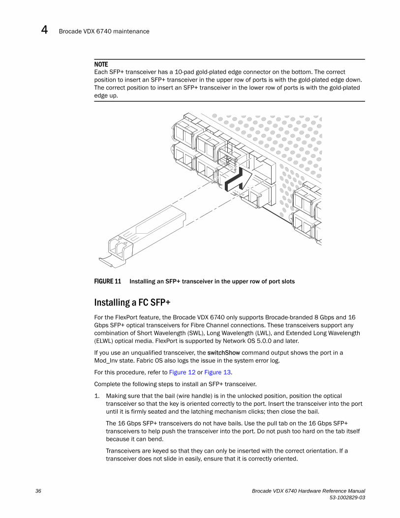
Brocade VDX 6740 maintenance4
NOTEEach SFP+ transceiver has a 10-pad gold-plated edge connector on the bottom. The correct position to insert an SFP+ transceiver in the upper row of ports is with the gold-plated edge down. The correct position to insert an SFP+ transceiver in the lower row of ports is with the gold-plated edge up.
FIGURE 11 Installing an SFP+ transceiver in the upper row of port slots
Installing a FC SFP+For the FlexPort feature, the Brocade VDX 6740 only supports Brocade-branded 8 Gbps and 16 Gbps SFP+ optical transceivers for Fibre Channel connections. These transceivers support any combination of Short Wavelength (SWL), Long Wavelength (LWL), and Extended Long Wavelength (ELWL) optical media. FlexPort is supported by Network OS 5.0.0 and later.
If you use an unqualified transceiver, the switchShow command output shows the port in a Mod_Inv state. Fabric OS also logs the issue in the system error log.
For this procedure, refer to Figure 12 or Figure 13.
Complete the following steps to install an SFP+ transceiver.
1. Making sure that the bail (wire handle) is in the unlocked position, position the optical transceiver so that the key is oriented correctly to the port. Insert the transceiver into the port until it is firmly seated and the latching mechanism clicks; then close the bail.
The 16 Gbps SFP+ transceivers do not have bails. Use the pull tab on the 16 Gbps SFP+ transceivers to help push the transceiver into the port. Do not push too hard on the tab itself because it can bend.
Transceivers are keyed so that they can only be inserted with the correct orientation. If a transceiver does not slide in easily, ensure that it is correctly oriented.
!
36 Brocade VDX 6740 Hardware Reference Manual53-1002829-03

Brocade VDX 6740 maintenance 4
2. Position a cable so that the key (the ridge on one side of the cable connector) is aligned with the slot in the transceiver. Insert the cable into the transceiver until the latching mechanism clicks.
Cables are keyed so that they can be inserted in only one way. If a cable does not slide in easily, ensure that it is correctly oriented.
NOTEEach SFP+ has a 10-pad gold-plated PCB-edge connector on the bottom. The correct position to insert an SFP+ into the upper row of ports is with the gold edge down. The correct position to insert an SFP+ into the lower row of ports is with the gold edge up.
FIGURE 12 Installing a 16 Gbps SFP+ in the upper row of port slot
!
Brocade VDX 6740 Hardware Reference Manual 3753-1002829-03
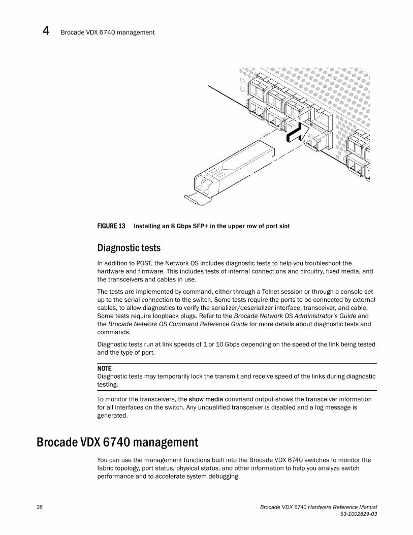
Brocade VDX 6740 management4
FIGURE 13 Installing an 8 Gbps SFP+ in the upper row of port slot
Diagnostic testsIn addition to POST, the Network OS includes diagnostic tests to help you troubleshoot the hardware and firmware. This includes tests of internal connections and circuitry, fixed media, and the transceivers and cables in use.
The tests are implemented by command, either through a Telnet session or through a console set up to the serial connection to the switch. Some tests require the ports to be connected by external cables, to allow diagnostics to verify the serializer/deserializer interface, transceiver, and cable. Some tests require loopback plugs. Refer to the Brocade Network OS Administrator’s Guide and the Brocade Network OS Command Reference Guide for more details about diagnostic tests and commands.
Diagnostic tests run at link speeds of 1 or 10 Gbps depending on the speed of the link being tested and the type of port.
NOTEDiagnostic tests may temporarily lock the transmit and receive speed of the links during diagnostic testing.
To monitor the transceivers, the show media command output shows the transceiver information for all interfaces on the switch. Any unqualified transceiver is disabled and a log message is generated.
Brocade VDX 6740 managementYou can use the management functions built into the Brocade VDX 6740 switches to monitor the fabric topology, port status, physical status, and other information to help you analyze switch performance and to accelerate system debugging.
38 Brocade VDX 6740 Hardware Reference Manual53-1002829-03
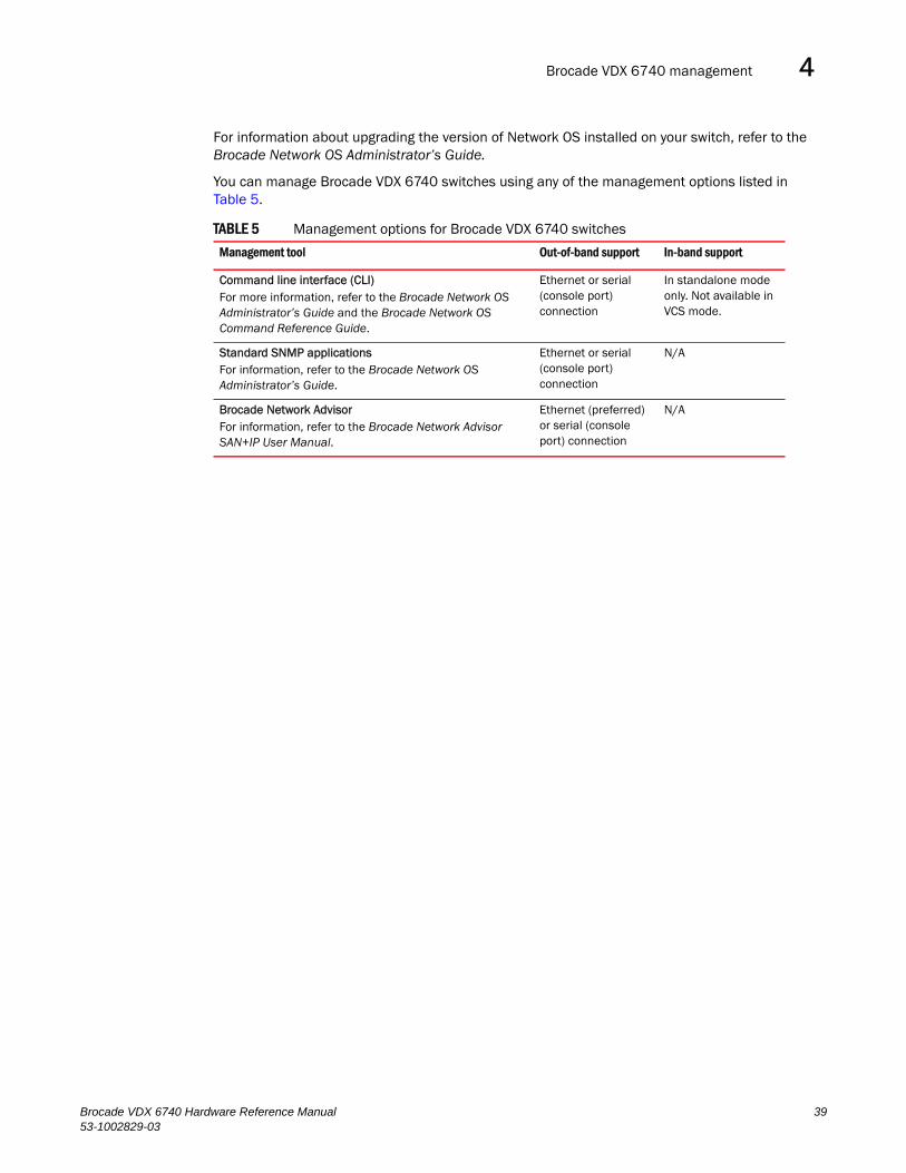
Brocade VDX 6740 management 4
For information about upgrading the version of Network OS installed on your switch, refer to the Brocade Network OS Administrator’s Guide.
You can manage Brocade VDX 6740 switches using any of the management options listed in Table 5.
TABLE 5 Management options for Brocade VDX 6740 switches
Management tool Out-of-band support In-band support
Command line interface (CLI)For more information, refer to the Brocade Network OS Administrator’s Guide and the Brocade Network OS Command Reference Guide.
Ethernet or serial (console port) connection
In standalone mode only. Not available in VCS mode.
Standard SNMP applicationsFor information, refer to the Brocade Network OS Administrator’s Guide.
Ethernet or serial (console port) connection
N/A
Brocade Network AdvisorFor information, refer to the Brocade Network Advisor SAN+IP User Manual.
Ethernet (preferred) or serial (console port) connection
N/A
Brocade VDX 6740 Hardware Reference Manual 3953-1002829-03

Brocade VDX 6740 management4
40 Brocade VDX 6740 Hardware Reference Manual53-1002829-03
Brocade VDX 6740 Hardware Reference Manual53-1002829-03
Chapter
5
Brocade VDX 6740 FRU Replacement ProceduresIn this chapter•Before beginning the installation . . . . . . . . . . . . . . . . . . . . . . . . . . . . . . . . . . 41
•Combined FRU replacement in a Brocade VDX 6740. . . . . . . . . . . . . . . . . . 42
•Power supply replacement in a Brocade 6740T and 6740T-1G. . . . . . . . . . 45
•Fan replacement in a Brocade VDX 6740T and Brocade VDX 6740T-1G . . 48
Before beginning the installation The field-replaceable units (FRUs) in the Brocade VDX 6740 switches can be removed and replaced without special tools. The switches can continue operating during the FRU replacements if the conditions specified in the procedures are followed. switches.
NOTERead the “Installation and safety considerations” on page 9 before servicing.
CAUTION
This document describes how to change field-replaceable units (FRUs) for switches with either a port-side air exhaust or a port-side air intake. You must replace a failed FRU with a FRU of the same type. This applies to both power supplies and fan assemblies.A new FRU must have the same part number (P/N) as the FRU being replaced. The manufacturing P/N is located on the top of the FRU.The P/N ends in either -F (front-to-rear airflow or exhaust) or -R (rear-to-front airflow or intake). You must use a replacement FRU that has the same airflow designator with the part number.
DANGER
The procedures in this manual are for qualified service personnel.
If a mismatched power source or fan assembly is installed by mistake, a warning is sent to the console. The warning messages will be similar to the following:
• For a fan mismatch: [WARNING, Brocade VDX 6740, MISMATCH in FAN Air Flow direction. Replace FRU with fan air flows in same direction.
• For a power supply or combined power supply and fan mismatch: [WARNING, Brocade VDX 6740, MISMATCH in PSU-FAN FRUS Air Flow direction. Replace PSU with fan air flows in same direction.
41
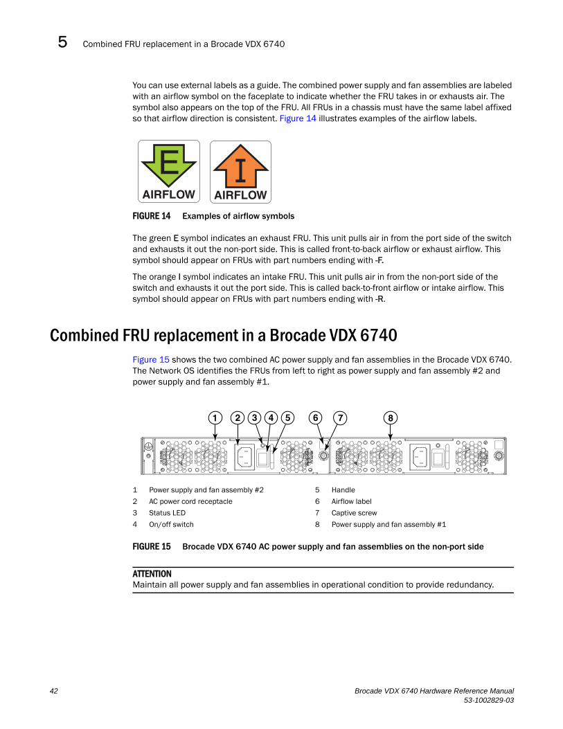
Combined FRU replacement in a Brocade VDX 67405
You can use external labels as a guide. The combined power supply and fan assemblies are labeled with an airflow symbol on the faceplate to indicate whether the FRU takes in or exhausts air. The symbol also appears on the top of the FRU. All FRUs in a chassis must have the same label affixed so that airflow direction is consistent. Figure 14 illustrates examples of the airflow labels.
FIGURE 14 Examples of airflow symbols
The green E symbol indicates an exhaust FRU. This unit pulls air in from the port side of the switch and exhausts it out the non-port side. This is called front-to-back airflow or exhaust airflow. This symbol should appear on FRUs with part numbers ending with -F.
The orange I symbol indicates an intake FRU. This unit pulls air in from the non-port side of the switch and exhausts it out the port side. This is called back-to-front airflow or intake airflow. This symbol should appear on FRUs with part numbers ending with -R.
Combined FRU replacement in a Brocade VDX 6740Figure 15 shows the two combined AC power supply and fan assemblies in the Brocade VDX 6740. The Network OS identifies the FRUs from left to right as power supply and fan assembly #2 and power supply and fan assembly #1.
FIGURE 15 Brocade VDX 6740 AC power supply and fan assemblies on the non-port side
ATTENTIONMaintain all power supply and fan assemblies in operational condition to provide redundancy.
AIRFLOW
EAIRFLOW
1 Power supply and fan assembly #2 5 Handle
2 AC power cord receptacle 6 Airflow label
3 Status LED 7 Captive screw
4 On/off switch 8 Power supply and fan assembly #1
2 3 71 54 86
42 Brocade VDX 6740 Hardware Reference Manual53-1002829-03
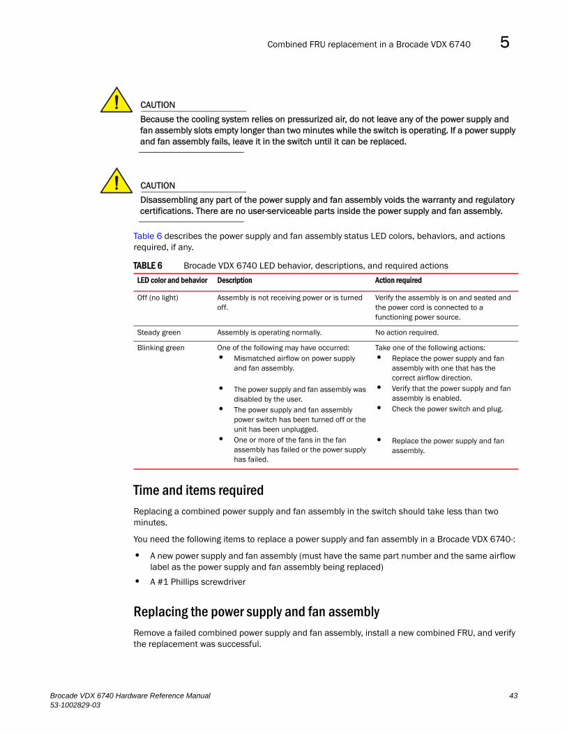
Combined FRU replacement in a Brocade VDX 6740 5
CAUTION
Because the cooling system relies on pressurized air, do not leave any of the power supply and fan assembly slots empty longer than two minutes while the switch is operating. If a power supply and fan assembly fails, leave it in the switch until it can be replaced.
CAUTION
Disassembling any part of the power supply and fan assembly voids the warranty and regulatory certifications. There are no user-serviceable parts inside the power supply and fan assembly.
Table 6 describes the power supply and fan assembly status LED colors, behaviors, and actions required, if any.
Time and items requiredReplacing a combined power supply and fan assembly in the switch should take less than two minutes.
You need the following items to replace a power supply and fan assembly in a Brocade VDX 6740-:
• A new power supply and fan assembly (must have the same part number and the same airflow label as the power supply and fan assembly being replaced)
• A #1 Phillips screwdriver
Replacing the power supply and fan assemblyRemove a failed combined power supply and fan assembly, install a new combined FRU, and verify the replacement was successful.
TABLE 6 Brocade VDX 6740 LED behavior, descriptions, and required actions
LED color and behavior Description Action required
Off (no light) Assembly is not receiving power or is turned off.
Verify the assembly is on and seated and the power cord is connected to a functioning power source.
Steady green Assembly is operating normally. No action required.
Blinking green One of the following may have occurred:• Mismatched airflow on power supply
and fan assembly.
• The power supply and fan assembly was disabled by the user.
• The power supply and fan assembly power switch has been turned off or the unit has been unplugged.
• One or more of the fans in the fan assembly has failed or the power supply has failed.
Take one of the following actions:• Replace the power supply and fan
assembly with one that has the correct airflow direction.
• Verify that the power supply and fan assembly is enabled.
• Check the power switch and plug.
• Replace the power supply and fan assembly.
Brocade VDX 6740 Hardware Reference Manual 4353-1002829-03
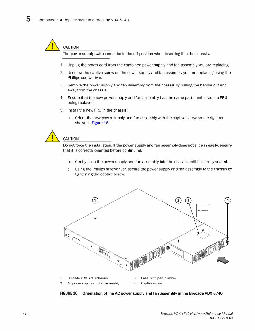
Combined FRU replacement in a Brocade VDX 67405
CAUTION
The power supply switch must be in the off position when inserting it in the chassis.
1. Unplug the power cord from the combined power supply and fan assembly you are replacing.
2. Unscrew the captive screw on the power supply and fan assembly you are replacing using the Phillips screwdriver.
3. Remove the power supply and fan assembly from the chassis by pulling the handle out and away from the chassis.
4. Ensure that the new power supply and fan assembly has the same part number as the FRU being replaced.
5. Install the new FRU in the chassis:
a. Orient the new power supply and fan assembly with the captive screw on the right as shown in Figure 16.
CAUTION
Do not force the installation. If the power supply and fan assembly does not slide in easily, ensure that it is correctly oriented before continuing.
b. Gently push the power supply and fan assembly into the chassis until it is firmly seated.
c. Using the Phillips screwdriver, secure the power supply and fan assembly to the chassis by tightening the captive screw.
FIGURE 16 Orientation of the AC power supply and fan assembly in the Brocade VDX 6740
1 Brocade VDX 6740 chassis 3 Label with part number
2 AC power supply and fan assembly 4 Captive screw
P/N: xxxxxxx-xx
3 41 2
44 Brocade VDX 6740 Hardware Reference Manual53-1002829-03
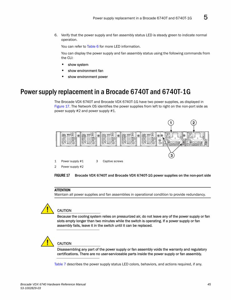
Power supply replacement in a Brocade 6740T and 6740T-1G 5
6. Verify that the power supply and fan assembly status LED is steady green to indicate normal operation.
You can refer to Table 6 for more LED information.
You can display the power supply and fan assembly status using the following commands from the CLI:
• show system
• show environment fan
• show environment power
Power supply replacement in a Brocade 6740T and 6740T-1GThe Brocade VDX 6740T and Brocade VDX 6740T-1G have two power supplies, as displayed in Figure 17. The Network OS identifies the power supplies from left to right on the non-port side as power supply #2 and power supply #1.
FIGURE 17 Brocade VDX 6740T and Brocade VDX 6740T-1G power supplies on the non-port side
ATTENTIONMaintain all power supplies and fan assemblies in operational condition to provide redundancy.
CAUTION
Because the cooling system relies on pressurized air, do not leave any of the power supply or fan slots empty longer than two minutes while the switch is operating. If a power supply or fan assembly fails, leave it in the switch until it can be replaced.
CAUTION
Disassembling any part of the power supply or fan assembly voids the warranty and regulatory certifications. There are no user-serviceable parts inside the power supply or fan assembly.
Table 7 describes the power supply status LED colors, behaviors, and actions required, if any.
1 Power supply #1 3 Captive screws
2 Power supply #2
Brocade VDX 6740 Hardware Reference Manual 4553-1002829-03
Power supply replacement in a Brocade 6740T and 6740T-1G5
Determining the need to replace a power supplyUse one of the following methods to determine the status of the power supplies:
• Check the power supply status LED.
• Enter one of the following commands in the command line interface to display power supply status:
- show chassis
- show environment power
• Check the power supply status in the Web Tools application.
Time and items requiredReplacing a power supply in the Brocade VDX 6740T and Brocade VDX 6740T-1G should take less than two minutes to complete.
You need the following items to replace a power supply in a Brocade VDX 6740T:
• A new power supply (must have the same part number and the same airflow label as the power supply being replaced)
• A #1 Phillips screwdriver
Replacing the power supplyComplete the following steps to replace a power supply in a Brocade VDX 6740T and Brocade VDX 6740T-1G.
1. To leave the Brocade VDX 6740T and Brocade VDX 6740T-1G in service while replacing a power supply, verify that the other power supply (the one not being replaced) has been powered on for at least four seconds and hasa steady green status LED.
2. Ensure that the replacement power supply has the same part number and airflow label as the power supply being replaced.
3. Unplug the power cord from the power supply that is being replaced.
4. Using the Phillips screwdriver, unscrew the two captive screws on the power supply.
TABLE 7 Brocade VDX 6740T and Brocade VDX 6740T-1G power supply status LED behavior, description, and required actions
LED color and behavior Description Action required
Off (no light) Power supply is not receiving power or is off. Verify that the power supply is on and seated and the power cord is connected to a functioning power source.
Steady green Power supply is operating normally. No action is required.
Blinking green Power supply cable is disconnected - blinking green for ~20 seconds, then off.The power supply has failed or the power supply airflow is different from system policy.
Check the power cable connection.
Check the power supply airflow direction and replace the power supply.
46 Brocade VDX 6740 Hardware Reference Manual53-1002829-03
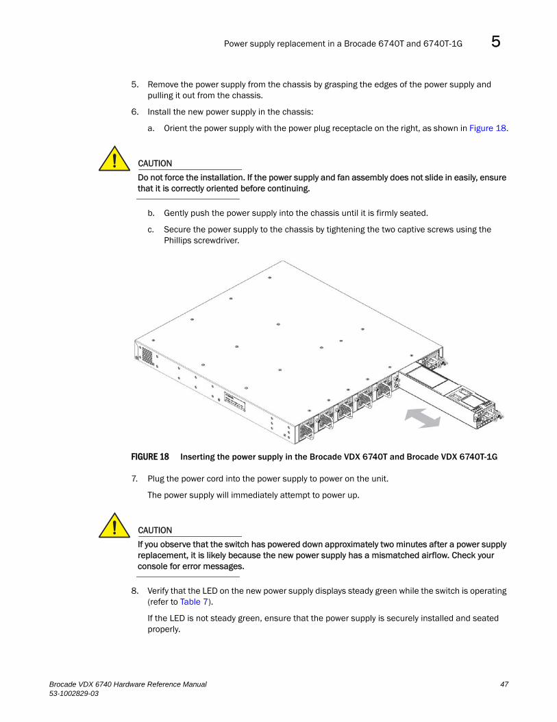
Power supply replacement in a Brocade 6740T and 6740T-1G 5
5. Remove the power supply from the chassis by grasping the edges of the power supply and pulling it out from the chassis.
6. Install the new power supply in the chassis:
a. Orient the power supply with the power plug receptacle on the right, as shown in Figure 18.
CAUTION
Do not force the installation. If the power supply and fan assembly does not slide in easily, ensure that it is correctly oriented before continuing.
b. Gently push the power supply into the chassis until it is firmly seated.
c. Secure the power supply to the chassis by tightening the two captive screws using the Phillips screwdriver.
FIGURE 18 Inserting the power supply in the Brocade VDX 6740T and Brocade VDX 6740T-1G
7. Plug the power cord into the power supply to power on the unit.
The power supply will immediately attempt to power up.
CAUTION
If you observe that the switch has powered down approximately two minutes after a power supply replacement, it is likely because the new power supply has a mismatched airflow. Check your console for error messages.
8. Verify that the LED on the new power supply displays steady green while the switch is operating (refer to Table 7).
If the LED is not steady green, ensure that the power supply is securely installed and seated properly.
Brocade VDX 6740 Hardware Reference Manual 4753-1002829-03
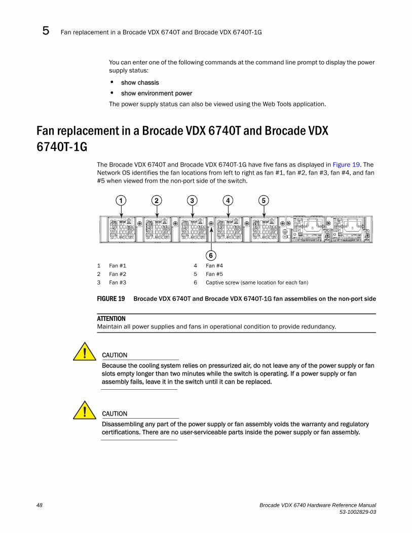
Fan replacement in a Brocade VDX 6740T and Brocade VDX 6740T-1G5
You can enter one of the following commands at the command line prompt to display the power supply status:
• show chassis
• show environment power
The power supply status can also be viewed using the Web Tools application.
Fan replacement in a Brocade VDX 6740T and Brocade VDX 6740T-1G
The Brocade VDX 6740T and Brocade VDX 6740T-1G have five fans as displayed in Figure 19. The Network OS identifies the fan locations from left to right as fan #1, fan #2, fan #3, fan #4, and fan #5 when viewed from the non-port side of the switch.
FIGURE 19 Brocade VDX 6740T and Brocade VDX 6740T-1G fan assemblies on the non-port side
ATTENTIONMaintain all power supplies and fans in operational condition to provide redundancy.
CAUTION
Because the cooling system relies on pressurized air, do not leave any of the power supply or fan slots empty longer than two minutes while the switch is operating. If a power supply or fan assembly fails, leave it in the switch until it can be replaced.
CAUTION
Disassembling any part of the power supply or fan assembly voids the warranty and regulatory certifications. There are no user-serviceable parts inside the power supply or fan assembly.
1 Fan #1 4 Fan #4
2 Fan #2 5 Fan #5
3 Fan #3 6 Captive screw (same location for each fan)
48 Brocade VDX 6740 Hardware Reference Manual53-1002829-03
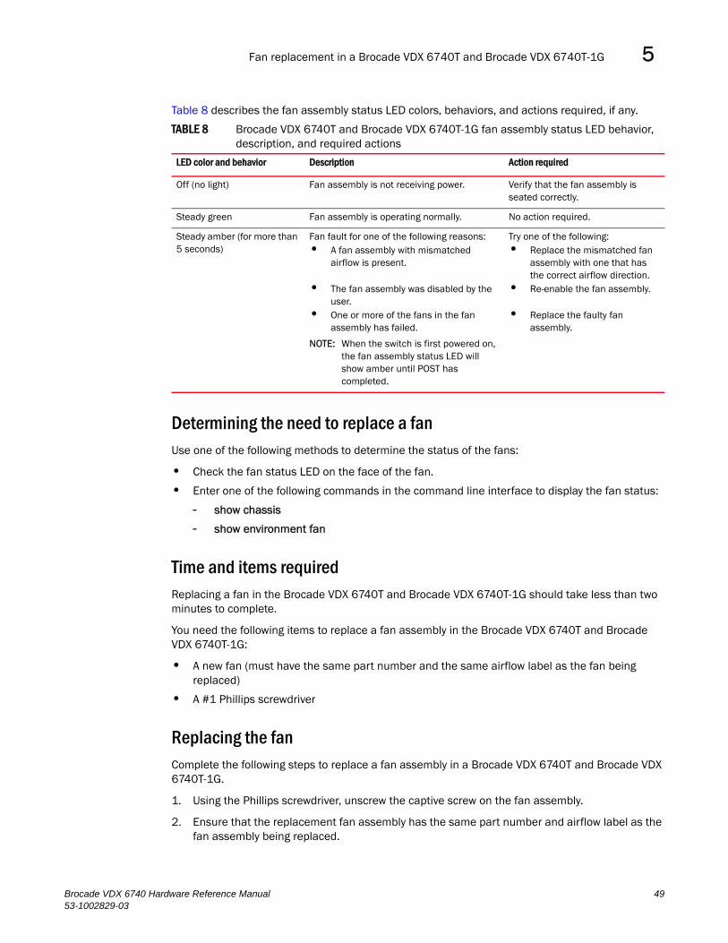
Fan replacement in a Brocade VDX 6740T and Brocade VDX 6740T-1G 5
Table 8 describes the fan assembly status LED colors, behaviors, and actions required, if any.
Determining the need to replace a fanUse one of the following methods to determine the status of the fans:
• Check the fan status LED on the face of the fan.
• Enter one of the following commands in the command line interface to display the fan status:
- show chassis
- show environment fan
Time and items requiredReplacing a fan in the Brocade VDX 6740T and Brocade VDX 6740T-1G should take less than two minutes to complete.
You need the following items to replace a fan assembly in the Brocade VDX 6740T and Brocade VDX 6740T-1G:
• A new fan (must have the same part number and the same airflow label as the fan being replaced)
• A #1 Phillips screwdriver
Replacing the fanComplete the following steps to replace a fan assembly in a Brocade VDX 6740T and Brocade VDX 6740T-1G.
1. Using the Phillips screwdriver, unscrew the captive screw on the fan assembly.
2. Ensure that the replacement fan assembly has the same part number and airflow label as the fan assembly being replaced.
TABLE 8 Brocade VDX 6740T and Brocade VDX 6740T-1G fan assembly status LED behavior, description, and required actions
LED color and behavior Description Action required
Off (no light) Fan assembly is not receiving power. Verify that the fan assembly is seated correctly.
Steady green Fan assembly is operating normally. No action required.
Steady amber (for more than 5 seconds)
Fan fault for one of the following reasons: • A fan assembly with mismatched
airflow is present.
• The fan assembly was disabled by the user.
• One or more of the fans in the fan assembly has failed.
NOTE: When the switch is first powered on, the fan assembly status LED will show amber until POST has completed.
Try one of the following:• Replace the mismatched fan
assembly with one that has the correct airflow direction.
• Re-enable the fan assembly.
• Replace the faulty fan assembly.
Brocade VDX 6740 Hardware Reference Manual 4953-1002829-03

Fan replacement in a Brocade VDX 6740T and Brocade VDX 6740T-1G5
3. Remove the fan assembly from the chassis by pulling the handle on the fan assembly out and away from the chassis.
4. Install the new fan assembly in the chassis:
a. Orient the new fan assembly with the captive screw on the right, as shown in Figure 20.
CAUTION
Do not force the installation. If the power supply and fan assembly does not slide in easily, ensure that it is correctly oriented before continuing.
b. Gently push the fan assembly into the chassis until it is firmly seated.
If the switch is powered up, the fan will immediately power up.
c. Using the Phillips screwdriver, secure the fan assembly to the chassis by tightening the captive screw.
FIGURE 20 Inserting the fan assembly in the Brocade VDX 6740T and Brocade VDX 6740T-1G
5. Verify that the fan status LED is steady green to indicate normal operation (refer to Table 8).
If the LED is not steady green, ensure that the fan is securely installed and seated properly.
You can enter one of the following commands at the command line prompt to display fan status:
• show chassis
• show environment fan
The fan status can also be viewed using the Web Tools application.
50 Brocade VDX 6740 Hardware Reference Manual53-1002829-03
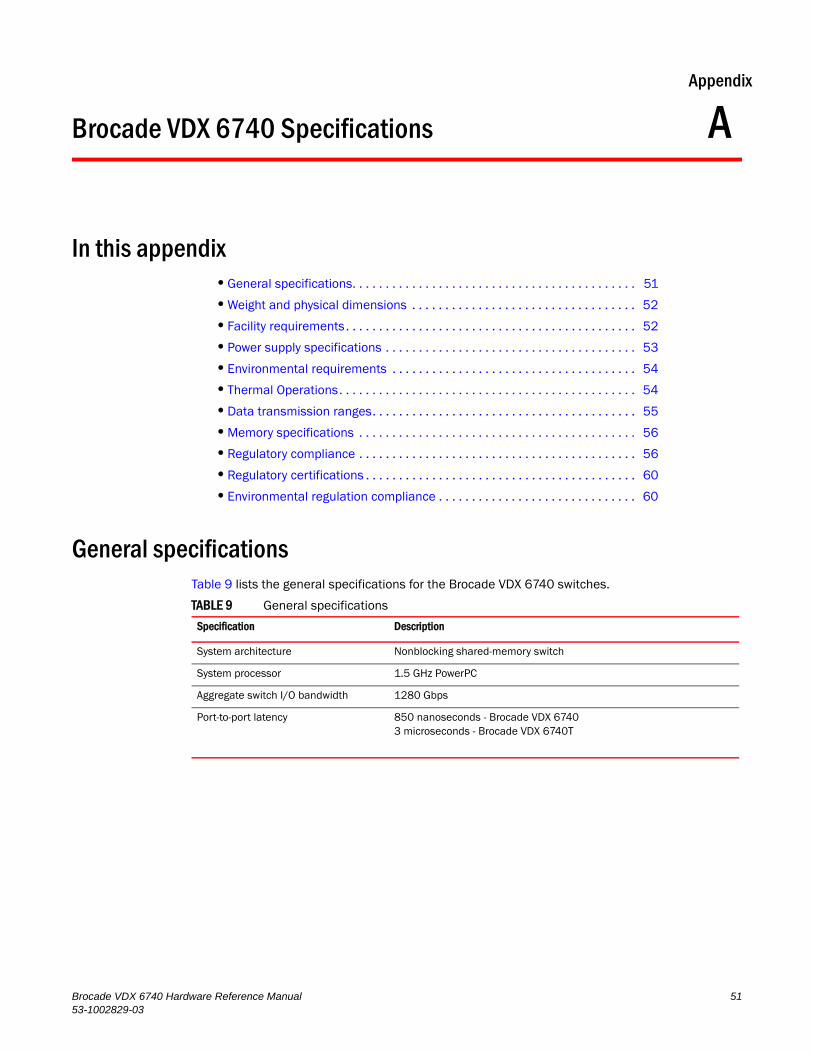
Brocade VDX 6740 Hardware Reference Manual53-1002829-03
Appendix
A
Brocade VDX 6740 SpecificationsIn this appendix•General specifications. . . . . . . . . . . . . . . . . . . . . . . . . . . . . . . . . . . . . . . . . . . 51
•Weight and physical dimensions . . . . . . . . . . . . . . . . . . . . . . . . . . . . . . . . . . 52
•Facility requirements. . . . . . . . . . . . . . . . . . . . . . . . . . . . . . . . . . . . . . . . . . . . 52
•Power supply specifications . . . . . . . . . . . . . . . . . . . . . . . . . . . . . . . . . . . . . . 53
•Environmental requirements . . . . . . . . . . . . . . . . . . . . . . . . . . . . . . . . . . . . . 54
•Thermal Operations. . . . . . . . . . . . . . . . . . . . . . . . . . . . . . . . . . . . . . . . . . . . . 54
•Data transmission ranges. . . . . . . . . . . . . . . . . . . . . . . . . . . . . . . . . . . . . . . . 55
•Memory specifications . . . . . . . . . . . . . . . . . . . . . . . . . . . . . . . . . . . . . . . . . . 56
•Regulatory compliance . . . . . . . . . . . . . . . . . . . . . . . . . . . . . . . . . . . . . . . . . . 56
•Regulatory certifications . . . . . . . . . . . . . . . . . . . . . . . . . . . . . . . . . . . . . . . . . 60
•Environmental regulation compliance . . . . . . . . . . . . . . . . . . . . . . . . . . . . . . 60
General specificationsTable 9 lists the general specifications for the Brocade VDX 6740 switches.
TABLE 9 General specifications
Specification Description
System architecture Nonblocking shared-memory switch
System processor 1.5 GHz PowerPC
Aggregate switch I/O bandwidth 1280 Gbps
Port-to-port latency 850 nanoseconds - Brocade VDX 67403 microseconds - Brocade VDX 6740T
51
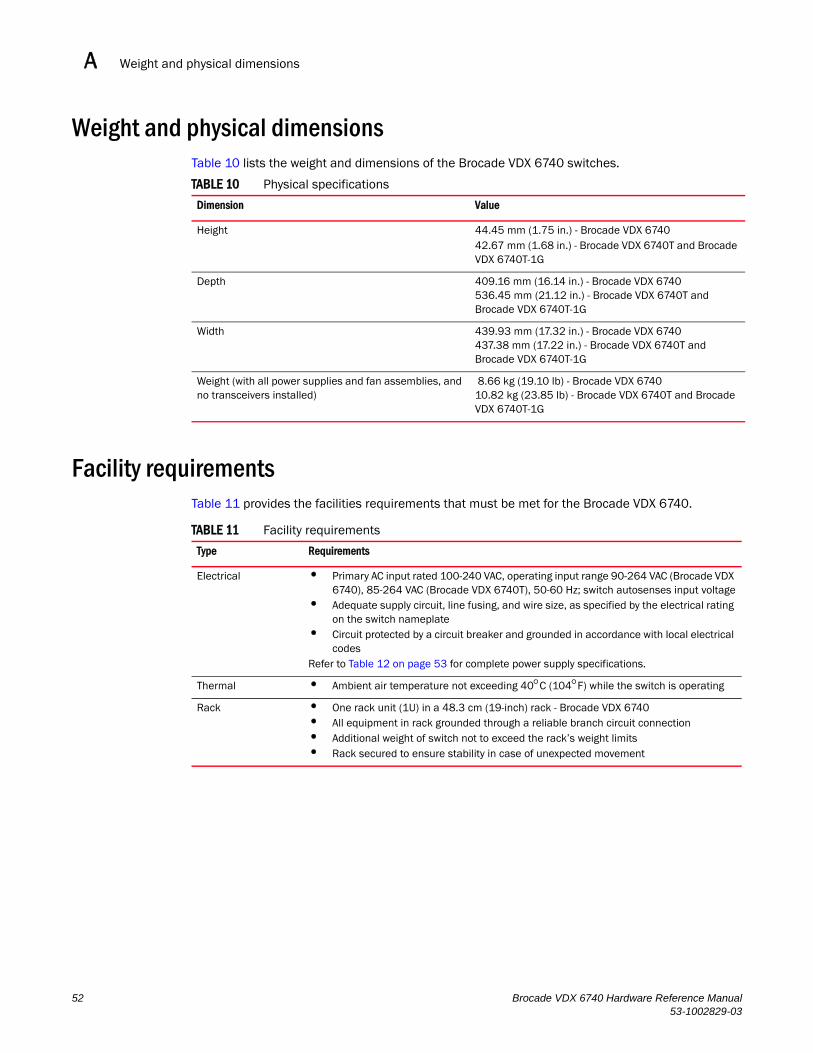
Weight and physical dimensionsA
Weight and physical dimensionsTable 10 lists the weight and dimensions of the Brocade VDX 6740 switches.
Facility requirementsTable 11 provides the facilities requirements that must be met for the Brocade VDX 6740.
TABLE 10 Physical specifications
Dimension Value
Height 44.45 mm (1.75 in.) - Brocade VDX 674042.67 mm (1.68 in.) - Brocade VDX 6740T and Brocade VDX 6740T-1G
Depth 409.16 mm (16.14 in.) - Brocade VDX 6740536.45 mm (21.12 in.) - Brocade VDX 6740T and Brocade VDX 6740T-1G
Width 439.93 mm (17.32 in.) - Brocade VDX 6740437.38 mm (17.22 in.) - Brocade VDX 6740T and Brocade VDX 6740T-1G
Weight (with all power supplies and fan assemblies, and no transceivers installed)
8.66 kg (19.10 lb) - Brocade VDX 674010.82 kg (23.85 lb) - Brocade VDX 6740T and Brocade VDX 6740T-1G
TABLE 11 Facility requirements
Type Requirements
Electrical • Primary AC input rated 100-240 VAC, operating input range 90-264 VAC (Brocade VDX 6740), 85-264 VAC (Brocade VDX 6740T), 50-60 Hz; switch autosenses input voltage
• Adequate supply circuit, line fusing, and wire size, as specified by the electrical rating on the switch nameplate
• Circuit protected by a circuit breaker and grounded in accordance with local electrical codes
Refer to Table 12 on page 53 for complete power supply specifications.
Thermal • Ambient air temperature not exceeding 40C (104F) while the switch is operating
Rack • One rack unit (1U) in a 48.3 cm (19-inch) rack - Brocade VDX 6740• All equipment in rack grounded through a reliable branch circuit connection• Additional weight of switch not to exceed the rack’s weight limits• Rack secured to ensure stability in case of unexpected movement
52 Brocade VDX 6740 Hardware Reference Manual53-1002829-03
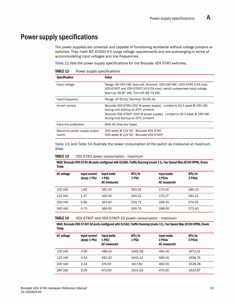
Power supply specifications A
Power supply specificationsThe power supplies are universal and capable of functioning worldwide without voltage jumpers or switches. They meet IEC 61000-4-5 surge voltage requirements and are autoranging in terms of accommodating input voltages and line frequencies.
Table 12 lists the power supply specifications for the Brocade VDX 6740 switches.
Table 13, and Table 14 illustrate the power consumption of the switch as measured at maximum draw.
TABLE 12 Power supply specifications
Specification Value
Input voltage Range: 90-264 VAC Auto-volt, Nominal: 100-240 VAC, (VDX 6740-3.5A max, VDX 6740T and VDX 6740T-1G 6.0A max); switch autosenses input voltageStart-up: 80-87 VAC, Turn-off: 85-75 VAC
Input frequency Range: 47-63 Hz; Nominal: 50-60 Hz
Inrush current Brocade VDX 6740 (250 W power supply) - Limited to 50 A peak @ 240 VAC during cold startup at 25ºC ambientBrocade VDX 6740T (500 W power supply) - Limited to 30 A peak @ 240 VAC during cold startup at 25ºC ambient
Input line protection Both AC lines are fused.
Maximum power supply output (each)
250 watts @ 12V DC - Brocade VDX 6740500 watts @ 12V DC - Brocade VDX 6740T
TABLE 13 VDX 6740 power consumption - maximum
MAX: Brocade VDX 6740 All ports configured with ELOAD, Traffic Running (mode 11), Fan Speed Max (8190 RPM), Room Temp
AC voltage Input current (Amp) 1 PSU
Input watts1 PSUAC measured
BTU/hr1 PSU
Input watts2 PSUsAC measured
BTU/hr2 PSUs
100 VAC 1.65 165.00 563.16 170.00 580.22
120 VAC 1.37 165.40 564.52 170.27 581.15
200 VAC 0.85 164.00 559.75 168.45 574.93
240 VAC 0.75 164.00 559.75 168.00 573.40
TABLE 14 VDX 6740T and VDX 6740T-1G power consumption - maximum
MAX: Brocade VDX 6740T All ports configured with ELOAD, Traffic Running (mode 11), Fan Speed Max (8190 RPM), Room Temp
AC voltage Input current (Amp) 1 PSU
Input watts1 PSUAC measured
BTU/hr1 PSU
Input watts2 PSUsAC measured
BTU/hr2 PSUs
100 VAC 4.90 488.00 1665.58 490.00 1672.41
120 VAC 4.53 482.00 1645.10 486.00 1658.76
200 VAC 2.44 474.00 1617.80 480.00 1638.28
240 VAC 2.05 473.00 1614.39 479.00 1634.87
Brocade VDX 6740 Hardware Reference Manual 5353-1002829-03
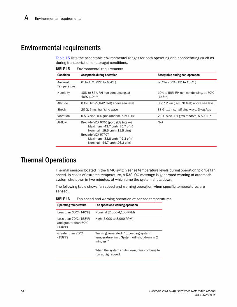
Environmental requirementsA
Environmental requirements Table 15 lists the acceptable environmental ranges for both operating and nonoperating (such as during transportation or storage) conditions.
Thermal OperationsThermal sensors located in the 6740 switch sense temperature levels during operation to drive fan speed. In cases of extreme temperature, a RASLOG message is generated warning of automatic system shutdown in two minutes, at which time the system shuts down.
The following table shows fan speed and warning operation when specific temperatures are sensed.
TABLE 15 Environmental requirements
Condition Acceptable during operation Acceptable during non-operation
Ambient Temperature
0º to 40ºC (32º to 104ºF) -25º to 70ºC (-13º to 158ºF)
Humidity 10% to 85% RH non-condensing, at 40ºC (104ºF)
10% to 90% RH non-condensing, at 70ºC (158ºF)
Altitude 0 to 3 km (9,842 feet) above sea level 0 to 12 km (39,370 feet) above sea level
Shock 20 G, 6 ms, half-sine wave 33 G, 11 ms, half-sine wave, 3/eg Axis
Vibration 0.5 G sine, 0.4 gms random, 5-500 Hz 2.0 G sine, 1.1 gms random, 5-500 Hz
Airflow Brocade VDX 6740 (port side intake)Maximum - 43.7 cmh (25.7 cfm)Nominal - 19.5 cmh (11.5 cfm)
Brocade VDX 6740TMaximum - 83.8 cmh (49.3 cfm) Nominal - 44.7 cmh (26.3 cfm)
N/A
TABLE 16 Fan speed and warning operation at sensed temperatures
Operating temperature Fan speed and warning operation
Less than 60ºC (140ºF) Nominal (2,000-4,100 RPM)
Less than 70ºC (158ºF) and greater than 60ºC (140ºF)
High (5,000 to 8,000 RPM)
Greater than 70ºC (158ºF)
Warning generated - “Exceeding system temperature limit. System will shut down in 2 minutes.”
When the system shuts down, fans continue to run at high speed.
54 Brocade VDX 6740 Hardware Reference Manual53-1002829-03
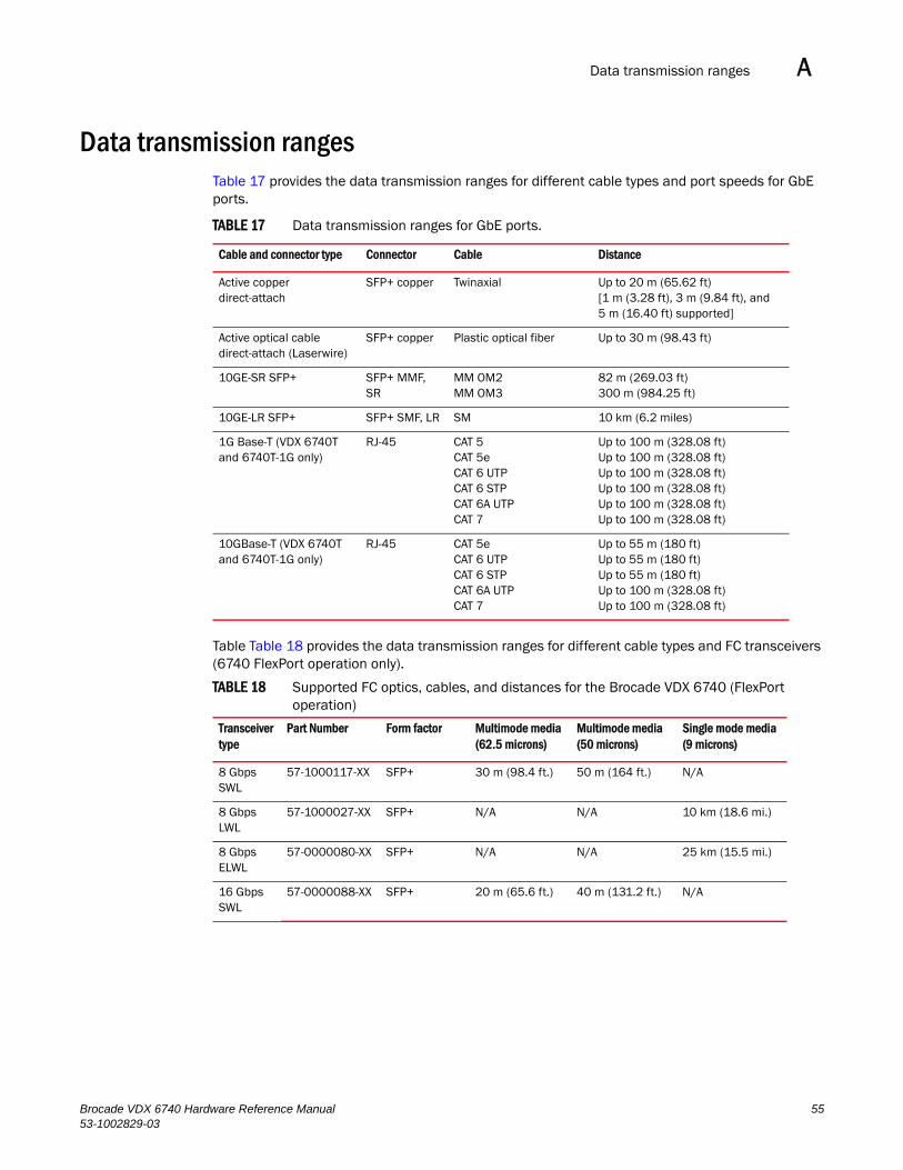
Data transmission ranges A
Data transmission rangesTable 17 provides the data transmission ranges for different cable types and port speeds for GbE ports.
TABLE 17 Data transmission ranges for GbE ports.
Table Table 18 provides the data transmission ranges for different cable types and FC transceivers (6740 FlexPort operation only).
Cable and connector type Connector Cable Distance
Active copper direct-attach
SFP+ copper Twinaxial Up to 20 m (65.62 ft)[1 m (3.28 ft), 3 m (9.84 ft), and 5 m (16.40 ft) supported]
Active optical cable direct-attach (Laserwire)
SFP+ copper Plastic optical fiber Up to 30 m (98.43 ft)
10GE-SR SFP+ SFP+ MMF, SR
MM OM2MM OM3
82 m (269.03 ft)300 m (984.25 ft)
10GE-LR SFP+ SFP+ SMF, LR SM 10 km (6.2 miles)
1G Base-T (VDX 6740T and 6740T-1G only)
RJ-45 CAT 5CAT 5eCAT 6 UTP CAT 6 STP CAT 6A UTPCAT 7
Up to 100 m (328.08 ft)Up to 100 m (328.08 ft)Up to 100 m (328.08 ft)Up to 100 m (328.08 ft)Up to 100 m (328.08 ft)Up to 100 m (328.08 ft)
10GBase-T (VDX 6740T and 6740T-1G only)
RJ-45 CAT 5eCAT 6 UTPCAT 6 STPCAT 6A UTPCAT 7
Up to 55 m (180 ft)Up to 55 m (180 ft)Up to 55 m (180 ft)Up to 100 m (328.08 ft)Up to 100 m (328.08 ft)
TABLE 18 Supported FC optics, cables, and distances for the Brocade VDX 6740 (FlexPort operation)
Transceiver type
Part Number Form factor Multimode media (62.5 microns)
Multimode media (50 microns)
Single mode media (9 microns)
8 Gbps SWL
57-1000117-XX SFP+ 30 m (98.4 ft.) 50 m (164 ft.) N/A
8 Gbps LWL
57-1000027-XX SFP+ N/A N/A 10 km (18.6 mi.)
8 Gbps ELWL
57-0000080-XX SFP+ N/A N/A 25 km (15.5 mi.)
16 Gbps SWL
57-0000088-XX SFP+ 20 m (65.6 ft.) 40 m (131.2 ft.) N/A
Brocade VDX 6740 Hardware Reference Manual 5553-1002829-03
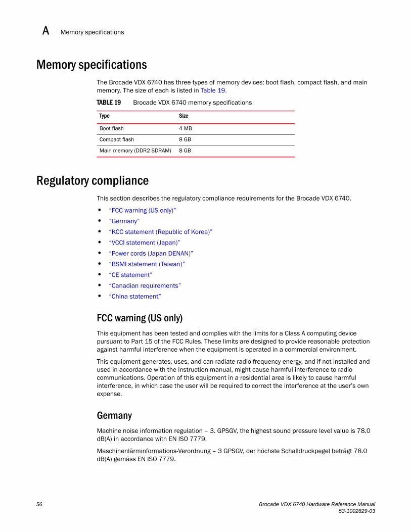
Memory specificationsA
Memory specifications The Brocade VDX 6740 has three types of memory devices: boot flash, compact flash, and main memory. The size of each is listed in Table 19.
TABLE 19 Brocade VDX 6740 memory specifications
Regulatory complianceThis section describes the regulatory compliance requirements for the Brocade VDX 6740.
• “FCC warning (US only)”
• “Germany”
• “KCC statement (Republic of Korea)”
• “VCCI statement (Japan)”
• “Power cords (Japan DENAN)”
• “BSMI statement (Taiwan)”
• “CE statement”
• “Canadian requirements”
• “China statement”
FCC warning (US only)This equipment has been tested and complies with the limits for a Class A computing device pursuant to Part 15 of the FCC Rules. These limits are designed to provide reasonable protection against harmful interference when the equipment is operated in a commercial environment.
This equipment generates, uses, and can radiate radio frequency energy, and if not installed and used in accordance with the instruction manual, might cause harmful interference to radio communications. Operation of this equipment in a residential area is likely to cause harmful interference, in which case the user will be required to correct the interference at the user’s own expense.
GermanyMachine noise information regulation – 3. GPSGV, the highest sound pressure level value is 78.0 dB(A) in accordance with EN ISO 7779.
Maschinenlärminformations-Verordnung – 3 GPSGV, der höchste Schalldruckpegel beträgt 78.0 dB(A) gemäss EN ISO 7779.
Type Size
Boot flash 4 MB
Compact flash 8 GB
Main memory (DDR2 SDRAM) 8 GB
56 Brocade VDX 6740 Hardware Reference Manual53-1002829-03
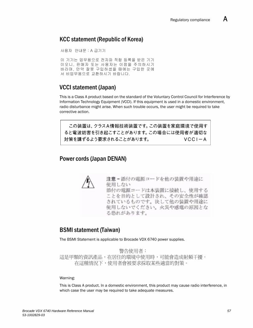
Regulatory compliance A
KCC statement (Republic of Korea)
VCCI statement (Japan)This is a Class A product based on the standard of the Voluntary Control Council for Interference by Information Technology Equipment (VCCI). If this equipment is used in a domestic environment, radio disturbance might arise. When such trouble occurs, the user might be required to take corrective action.
Power cords (Japan DENAN)
BSMI statement (Taiwan)The BSMI Statement is applicable to Brocade VDX 6740 power supplies.
Warning:
This is Class A product. In a domestic environment, this product may cause radio interference, in which case the user may be required to take adequate measures.
Brocade VDX 6740 Hardware Reference Manual 5753-1002829-03

Regulatory complianceA
CE statement
NOTEThis is a Class A product. In a domestic environment, this product might cause radio interference, and the user might be required to take corrective measures
The standards compliance label on the Brocade VDX 6740 contains the CE mark which indicates that this system conforms to the provisions of the following European Council directives, laws, and standards:
• Electromagnetic Compatibility (EMC) Directive 2004/108/EEC
• Low Voltage Directive (LVD) 2006/95/EC
• EN50082-2/EN55024:1998 (European Immunity Requirements)
- EN61000-3-2/JEIDA (European and Japanese Harmonics Spec)
- EN61000-3-3
Canadian requirementsThis Class A digital apparatus meets all requirements of the Canadian Interference-Causing Equipment Regulations, ICES-003 Class A.
Cet appareil numérique de la classe A est conforme à la norme NMB-003 du Canada.
58 Brocade VDX 6740 Hardware Reference Manual53-1002829-03
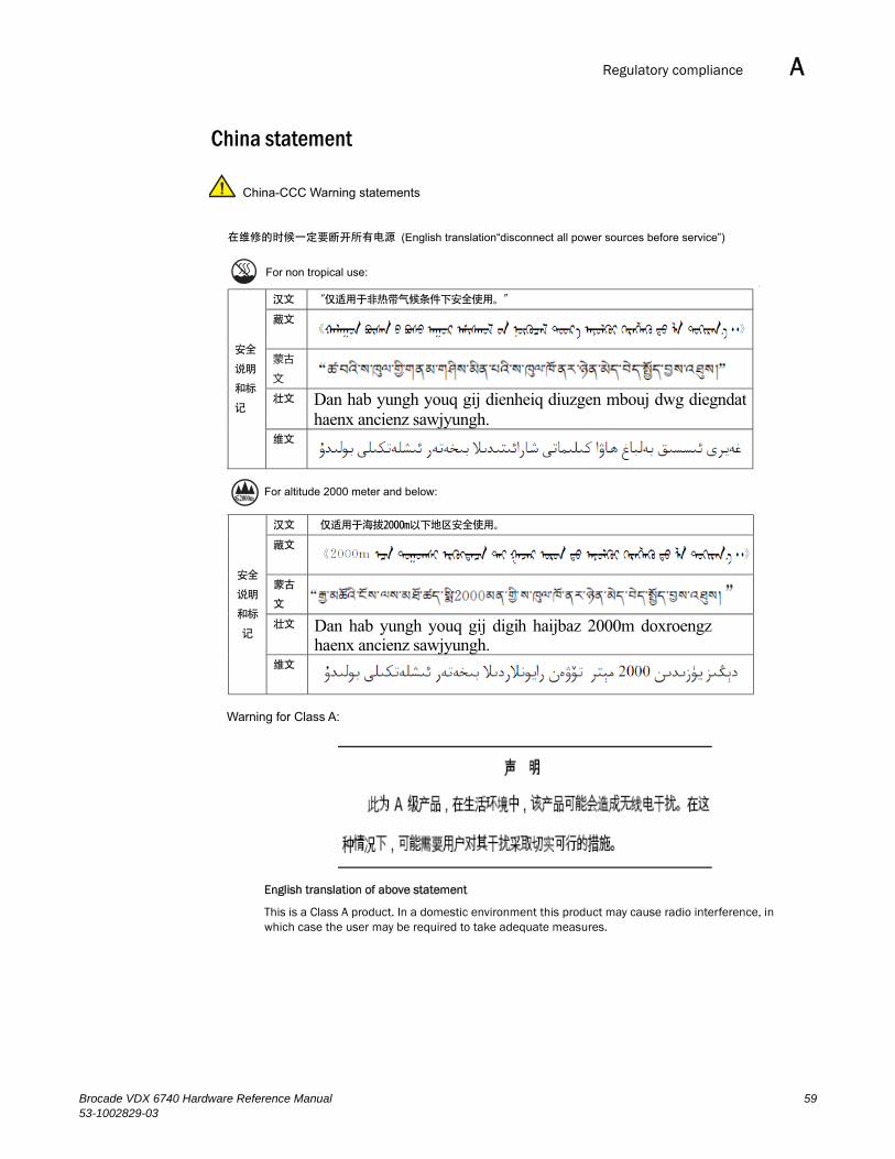
Regulatory compliance A
China statement
汉文 “仅适用于非热带气候条件下安全使用。”
藏文
蒙古
文
壮文 Dan hab yungh youq gij dienheiq diuzgen mbouj dwg diegndat haenx ancienz sawjyungh.
安全
说明
和标
记
维文
汉文 仅适用于海拔2000m以下地区安全使用。
藏文
蒙古
文
壮文 Dan hab yungh youq gij digih haijbaz 2000m doxroengz haenx ancienz sawjyungh.
安全
说明
和标
记
维文
在维修的时候一定要断开所有电源 (English translation“disconnect all power sources before service”)
For non tropical use:
For altitude 2000 meter and below:
China-CCC Warning statements
English translation of above statement
This is a Class A product. In a domestic environment this product may cause radio interference, in which case the user may be required to take adequate measures.
Warning for Class A:
Brocade VDX 6740 Hardware Reference Manual 5953-1002829-03
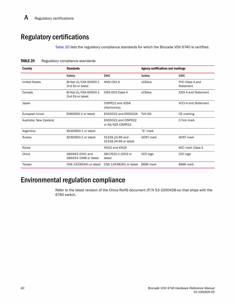
Regulatory certificationsA
Regulatory certificationsTable 20 lists the regulatory compliance standards for which the Brocade VDX 6740 is certified.
Environmental regulation complianceRefer to the latest revision of the China RoHS document (P/N 53-1000428-xx) that ships with the 6740 switch.
TABLE 20 Regulatory compliance standards
Country Standards Agency certifications and markings
Safety EMC Safety EMC
United States Bi-Nat UL/CSA 60950-1 2nd Ed or latest
ANSI C63.4 cCSAus FCC Class A and Statement
Canada Bi-Nat UL/CSA 60950-1 2nd Ed or latest
ICES-003 Class A cCSAus ICES A and Statement
Japan CISPR22 and JEIDA(Harmonics)
VCCI-A and Statement
European Union EN60950-1 or latest EN55022 and EN55024 TUV-GS CE marking
Australia, New Zealand EN55022 and CISPR22or AS/NZS CISPR22
C-Tick mark
Argentina IEC60950-1 or latest “S” mark
Russia IEC60950-1 or latest 51318.22-99 and 51318.24-99 or latest
GOST mark GOST mark
Korea KN22 and KN24 KCC mark Class A
China GB4943-2001 and GB9254-1998 or latest
GB17625.1-2003 or latest
CCC logo CCC logo
Taiwan CNS 14336(94) or latest CNS 13438(95) or latest BSMI mark BSMI mark
60 Brocade VDX 6740 Hardware Reference Manual53-1002829-03
Brocade VDX 6740 Hardware Reference Manual53-1002829-03
Appendix
B
Caution and Danger NoticesIn this appendix•Caution notices . . . . . . . . . . . . . . . . . . . . . . . . . . . . . . . . . . . . . . . . . . . . . . . . 61
•Danger notices. . . . . . . . . . . . . . . . . . . . . . . . . . . . . . . . . . . . . . . . . . . . . . . . . 64
•Electrical cautions . . . . . . . . . . . . . . . . . . . . . . . . . . . . . . . . . . . . . . . . . . . . . . 66
Caution noticesThe cautions that appear in this manual are listed in this section in English, German, French, and Spanish.
A caution calls your attention to a possible hazard that can damage equipment.
"Vorsicht" weist auf eine mögliche Beschädigung des Geräts hin. Sie finden die folgenden Vorsichtshinweise in diesem Handbuch.
Une mise en garde attire votre attention sur un risque possible d'endommagement de l'équipement. Ci-dessous, vous trouverez les mises en garde utilisées dans ce manuel.
Un mensaje de precaución le advierte sobre un posible peligro que pueda dañar el equipo. Las siguientes son precauciones utilizadas en este manual.
61
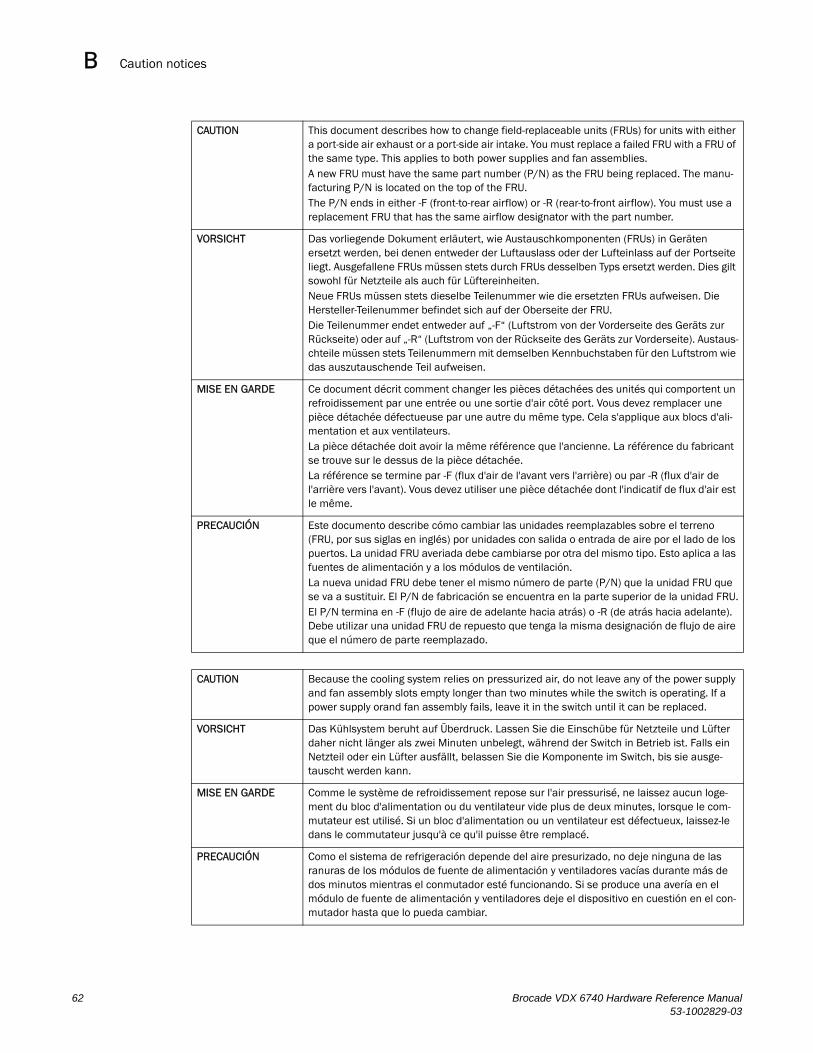
Caution noticesB
CAUTION This document describes how to change field-replaceable units (FRUs) for units with either a port-side air exhaust or a port-side air intake. You must replace a failed FRU with a FRU of the same type. This applies to both power supplies and fan assemblies.A new FRU must have the same part number (P/N) as the FRU being replaced. The manu-facturing P/N is located on the top of the FRU.The P/N ends in either -F (front-to-rear airflow) or -R (rear-to-front airflow). You must use a replacement FRU that has the same airflow designator with the part number.
VORSICHT Das vorliegende Dokument erläutert, wie Austauschkomponenten (FRUs) in Geräten ersetzt werden, bei denen entweder der Luftauslass oder der Lufteinlass auf der Portseite liegt. Ausgefallene FRUs müssen stets durch FRUs desselben Typs ersetzt werden. Dies gilt sowohl für Netzteile als auch für Lüftereinheiten.Neue FRUs müssen stets dieselbe Teilenummer wie die ersetzten FRUs aufweisen. Die Hersteller-Teilenummer befindet sich auf der Oberseite der FRU.Die Teilenummer endet entweder auf „-F“ (Luftstrom von der Vorderseite des Geräts zur Rückseite) oder auf „-R“ (Luftstrom von der Rückseite des Geräts zur Vorderseite). Austaus-chteile müssen stets Teilenummern mit demselben Kennbuchstaben für den Luftstrom wie das auszutauschende Teil aufweisen.
MISE EN GARDE Ce document décrit comment changer les pièces détachées des unités qui comportent un refroidissement par une entrée ou une sortie d'air côté port. Vous devez remplacer une pièce détachée défectueuse par une autre du même type. Cela s'applique aux blocs d'ali-mentation et aux ventilateurs.La pièce détachée doit avoir la même référence que l'ancienne. La référence du fabricant se trouve sur le dessus de la pièce détachée.La référence se termine par -F (flux d'air de l'avant vers l'arrière) ou par -R (flux d'air de l'arrière vers l'avant). Vous devez utiliser une pièce détachée dont l'indicatif de flux d'air est le même.
PRECAUCIÓN Este documento describe cómo cambiar las unidades reemplazables sobre el terreno (FRU, por sus siglas en inglés) por unidades con salida o entrada de aire por el lado de los puertos. La unidad FRU averiada debe cambiarse por otra del mismo tipo. Esto aplica a las fuentes de alimentación y a los módulos de ventilación.La nueva unidad FRU debe tener el mismo número de parte (P/N) que la unidad FRU que se va a sustituir. El P/N de fabricación se encuentra en la parte superior de la unidad FRU.El P/N termina en -F (flujo de aire de adelante hacia atrás) o -R (de atrás hacia adelante). Debe utilizar una unidad FRU de repuesto que tenga la misma designación de flujo de aire que el número de parte reemplazado.
CAUTION Because the cooling system relies on pressurized air, do not leave any of the power supply and fan assembly slots empty longer than two minutes while the switch is operating. If a power supply orand fan assembly fails, leave it in the switch until it can be replaced.
VORSICHT Das Kühlsystem beruht auf Überdruck. Lassen Sie die Einschübe für Netzteile und Lüfter daher nicht länger als zwei Minuten unbelegt, während der Switch in Betrieb ist. Falls ein Netzteil oder ein Lüfter ausfällt, belassen Sie die Komponente im Switch, bis sie ausge-tauscht werden kann.
MISE EN GARDE Comme le système de refroidissement repose sur l'air pressurisé, ne laissez aucun loge-ment du bloc d'alimentation ou du ventilateur vide plus de deux minutes, lorsque le com-mutateur est utilisé. Si un bloc d'alimentation ou un ventilateur est défectueux, laissez-le dans le commutateur jusqu'à ce qu'il puisse être remplacé.
PRECAUCIÓN Como el sistema de refrigeración depende del aire presurizado, no deje ninguna de las ranuras de los módulos de fuente de alimentación y ventiladores vacías durante más de dos minutos mientras el conmutador esté funcionando. Si se produce una avería en el módulo de fuente de alimentación y ventiladores deje el dispositivo en cuestión en el con-mutador hasta que lo pueda cambiar.
62 Brocade VDX 6740 Hardware Reference Manual53-1002829-03
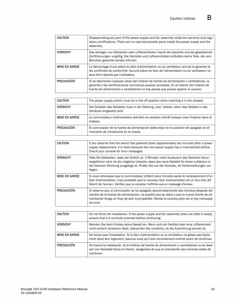
Caution notices B
CAUTION Disassembling any part of the power supply and fan assembly voids the warranty and regu-latory certifications. There are no user-serviceable parts inside the power supply and fan assembly.
VORSICHT Das Zerlegen von Netzteilen oder Lüftereinheiten macht die Garantie und die gesetzlichen Zertifizierungen ungültig. Die Netzteile und Lüftereinheiten enthalten keine Teile, die vom Benutzer gewartet werden können.
MISE EN GARDE Le démontage d'une pièce du bloc d'alimentation ou du ventilateur annule la garantie et les certificats de conformité. Aucune pièce du bloc de l'alimentation ou du ventilateur ne peut être réparée par l'utilisateur.
PRECAUCIÓN Si se desmonta cualquier pieza del módulo de fuente de alimentación y ventiladores, la garantía y las certificaciones normativas quedan anuladas. En el interior del módulo de fuente de alimentación y ventiladores no hay piezas que pueda reparar el usuario.
CAUTION The power supply switch must be in the off position when inserting it in the chassis.
VORSICHT Der Schalter des Netzteils muss in der Stellung „Aus“ stehen, wenn das Netzteil in das Gehäuse eingesetzt wird.
MISE EN GARDE Le commutateur d'alimentation doit être en position d'arrêt lorsque vous l'insérez dans le châssis.
PRECAUCIÓN El conmutador de la fuente de alimentación debe estar en la posición de apagado en el momento de introducirla en el chasis.
CAUTION If you observe that the switch has powered down approximately two minutes after a power supply replacement, it is likely because the new power supply has a mismatched airflow. Check your console for error messages.
VORSICHT Falls Sie feststellen, dass der Switch ca. 2 Minuten nach Austausch des Netzteils herun-tergefahren wird, ist die mögliche Ursache, dass das neue Netzteil für einen Luftstrom in der falschen Richtung ausgelegt ist. Prüfen Sie auf der Konsole, ob Fehlermeldungen vor-liegen.
MISE EN GARDE Si vous remarquez que le commutateur s'éteint deux minutes après le remplacement d'un bloc d'alimentation, il est probable que le nouveau bloc d'alimentation ait un flux d'air dif-férent de l'ancien. Vérifiez que la console n'affiche aucun message d'erreur.
PRECAUCIÓN Si observa que el conmutador se ha apagado aproximadamente dos minutos después del cambio de la fuente de alimentación, es posible que se deba a que la nueva fuente de ali-mentación tenga un flujo de aire incompatible. Revise la consola para ver si hay mensajes de error.
CAUTION Do not force the installation. If the power supply and fan assembly does not slide in easily, ensure that it is correctly oriented before continuing.
VORSICHT Wenden Sie beim Einbau keine Gewalt an. Wenn sich ein Netzteil oder eine Lüftereinheit nicht einfach einsetzen lässt, überprüfen Sie zunächst, ob die Ausrichtung korrekt ist.
MISE EN GARDE Ne forcez pas l'installation. Si le bloc d'alimentation ou le ventilateur ne glisse pas facile-ment dans leur logement, assurez-vous qu'il soit correctement orienté avant de continuer.
PRECAUCIÓN No fuerce la instalación. Si el módulo de fuente de alimentación y ventiladores no se desli-zan con facilidad hacia el interior, asegúrese de que la orientación sea correcta antes de continuar.
Brocade VDX 6740 Hardware Reference Manual 6353-1002829-03
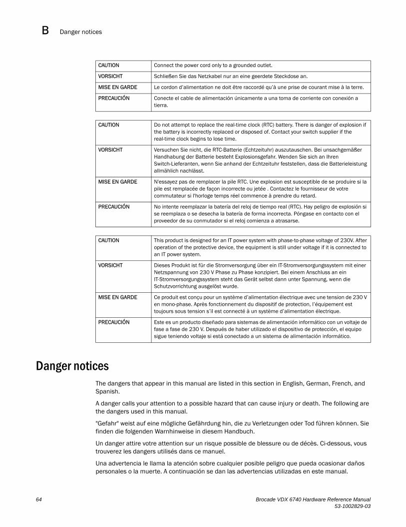
Danger noticesB
Danger noticesThe dangers that appear in this manual are listed in this section in English, German, French, and Spanish.
A danger calls your attention to a possible hazard that can cause injury or death. The following are the dangers used in this manual.
"Gefahr" weist auf eine mögliche Gefährdung hin, die zu Verletzungen oder Tod führen können. Sie finden die folgenden Warnhinweise in diesem Handbuch.
Un danger attire votre attention sur un risque possible de blessure ou de décès. Ci-dessous, vous trouverez les dangers utilisés dans ce manuel.
Una advertencia le llama la atención sobre cualquier posible peligro que pueda ocasionar daños personales o la muerte. A continuación se dan las advertencias utilizadas en este manual.
CAUTION Connect the power cord only to a grounded outlet.
VORSICHT Schließen Sie das Netzkabel nur an eine geerdete Steckdose an.
MISE EN GARDE Le cordon d’alimentation ne doit être raccordé qu’à une prise de courant mise à la terre.
PRECAUCIÓN Conecte el cable de alimentación únicamente a una toma de corriente con conexión a tierra.
CAUTION Do not attempt to replace the real-time clock (RTC) battery. There is danger of explosion if the battery is incorrectly replaced or disposed of. Contact your switch supplier if the real-time clock begins to lose time.
VORSICHT Versuchen Sie nicht, die RTC-Batterie (Echtzeituhr) auszutauschen. Bei unsachgemäßer Handhabung der Batterie besteht Explosionsgefahr. Wenden Sie sich an Ihren Switch-Lieferanten, wenn Sie anhand der Echtzeituhr feststellen, dass die Batterieleistung allmählich nachlässt.
MISE EN GARDE N'essayez pas de remplacer la pile RTC. Une explosion est susceptible de se produire si la pile est remplacée de façon incorrecte ou jetée . Contactez le fournisseur de votre commutateur si l'horloge temps réel commence à prendre du retard.
PRECAUCIÓN No intente reemplazar la batería del reloj de tiempo real (RTC). Hay peligro de explosión si se reemplaza o se desecha la batería de forma incorrecta. Póngase en contacto con el proveedor de su conmutador si el reloj comienza a atrasarse.
CAUTION This product is designed for an IT power system with phase-to-phase voltage of 230V. After operation of the protective device, the equipment is still under voltage if it is connected to an IT power system.
VORSICHT Dieses Produkt ist für die Stromversorgung über ein IT-Stromversorgungssystem mit einer Netzspannung von 230 V Phase zu Phase konzipiert. Bei einem Anschluss an ein IT-Stromversorgungssystem steht das Gerät selbst dann unter Spannung, wenn die Schutzvorrichtung ausgelöst wurde.
MISE EN GARDE Ce produit est conçu pour un système d’alimentation électrique avec une tension de 230 V en mono-phase. Après fonctionnement du dispositif de protection, l’équipement est toujours sous tension s’il est connecté à un système d’alimentation électrique.
PRECAUCIÓN Este es un producto diseñado para sistemas de alimentación informático con un voltaje de fase a fase de 230 V. Después de haber utilizado el dispositivo de protección, el equipo sigue teniendo voltaje si está conectado a un sistema de alimentación informático.
64 Brocade VDX 6740 Hardware Reference Manual53-1002829-03
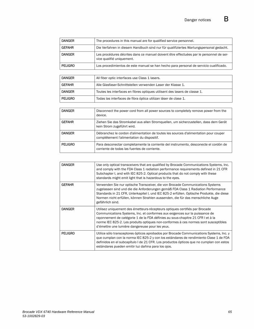
Danger notices B
DANGER The procedures in this manual are for qualified service personnel.
GEFAHR Die Verfahren in diesem Handbuch sind nur für qualifiziertes Wartungspersonal gedacht.
DANGER Les procédures décrites dans ce manuel doivent être effectuées par le personnel de ser-vice qualifié uniquement.
PELIGRO Los procedimientos de este manual se han hecho para personal de servicio cualificado.
DANGER All fiber optic interfaces use Class 1 lasers.
GEFAHR Alle Glasfaser-Schnittstellen verwenden Laser der Klasse 1.
DANGER Toutes les interfaces en fibres optiques utilisent des lasers de classe 1.
PELIGRO Todas las interfaces de fibra óptica utilizan láser de clase 1.
DANGER Disconnect the power cord from all power sources to completely remove power from the device.
GEFAHR Ziehen Sie das Stromkabel aus allen Stromquellen, um sicherzustellen, dass dem Gerät kein Strom zugeführt wird.
DANGER Débranchez le cordon d'alimentation de toutes les sources d'alimentation pour couper complètement l'alimentation du dispositif.
PELIGRO Para desconectar completamente la corriente del instrumento, desconecte el cordón de corriente de todas las fuentes de corriente.
DANGER Use only optical transceivers that are qualified by Brocade Communications Systems, Inc. and comply with the FDA Class 1 radiation performance requirements defined in 21 CFR Subchapter I, and with IEC 825-2. Optical products that do not comply with these standards might emit light that is hazardous to the eyes.
GEFAHR Verwenden Sie nur optische Transceiver, die von Brocade Communications Systems zugelassen sind und die die Anforderungen gemäß FDA Class 1 Radiation Performance Standards in 21 CFR, Unterkapitel I, und IEC 825-2 erfüllen. Optische Produkte, die diese Normen nicht erfüllen, können Strahlen aussenden, die für das menschliche Auge gefährlich sind.
DANGER Utilisez uniquement des émetteurs-récepteurs optiques certifiés par Brocade Communications Systems, Inc. et conformes aux exigences sur la puissance de rayonnement de catégorie 1 de la FDA définies au sous-chapitre 21 CFR I et à la norme IEC 825-2. Les produits optiques non-conformes à ces normes sont susceptibles d’émettre une lumière dangereuse pour les yeux.
PELIGRO Utilice sólo transceptores ópticos aprobados por Brocade Communications Systems, Inc. y que cumplan con la norma IEC 825-2 y con los estándares de rendimiento Clase 1 de FDA definidos en el subcapítulo I de 21 CFR. Los productos ópticos que no cumplan con estos estándares pueden emitir luz dañina para los ojos.
Brocade VDX 6740 Hardware Reference Manual 6553-1002829-03
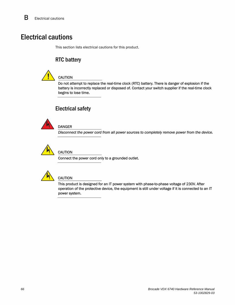
Electrical cautionsB
Electrical cautionsThis section lists electrical cautions for this product.
RTC battery
CAUTION
Do not attempt to replace the real-time clock (RTC) battery. There is danger of explosion if the battery is incorrectly replaced or disposed of. Contact your switch supplier if the real-time clock begins to lose time.
Electrical safety
DANGER
Disconnect the power cord from all power sources to completely remove power from the device.
CAUTION
Connect the power cord only to a grounded outlet.
CAUTION
This product is designed for an IT power system with phase-to-phase voltage of 230V. After operation of the protective device, the equipment is still under voltage if it is connected to an IT power system.
66 Brocade VDX 6740 Hardware Reference Manual53-1002829-03
Index
Numerics6740 switch, 16740T switch, 16740T-1G switch, 1
upgrading port speed, 24
Aaccessing NTP server, 21airflow
symbols, 42
Bbandwidth limitation for trunks, 23base model switches, 1battery, RTC, 66boot, 34boot flash memory, 56Brocade Network Advisor, 39BSMI statement (Taiwan), 57
Ccable
bending limit, 11management, 11slack, 11wraps, 11
Canadian requirements, 58caution statements, translated, 61, 64CE statement, 58changing rbridge-id, 19changing the vcs-id, 19CLI, 39clock set command, 21clock timezone command, 20, 21
commandclock set, 21clock timezone, 20, 21configure terminal, 17, 19fastboot, 33interface management, 17ip address, 18ip address dhcp, 18ip gateway-address, 18ipv6 address autoconfig, 19no diag post, 33no ipv6 address autoconfig, 19no ntp server, 21ntp server, 20, 21show chassis, 46, 49show clock, 21show environment fan, 49show environment power, 46show logging raslog, 34show media, 38show ntp status, 21show running-config, 18switchShow, 36username, 17vcs rbridge-id, 19vcs vcs-id, 19
command line interfacesee CLI
compact flash memory, 56configuration
date and time, 20modes, 15provide power, 12serial connection, 16switch IP address, 17terminal emulator, 16
configure terminal command, 17, 19connecting
Ethernet hubs, 22workstations, servers, routers, 22
connecting network devices, 22crossover cable, 22
Brocade VDX 6740 Hardware Reference Manual 6753-1002829-03
Ddanger statements, translated, 64data transmission ranges, 55diagnostic tests, 38distributed intelligence, 15
Eelectrical
considerations, 10safety, 66
EMC compliance, 60environmental
considerations, 10requirements, 54
event date and time, 20
Ffacility requirements, 52fan assembly, replacing, 48fan, VDX 6740, 42fan, VDX 6740-T and 6740T-1G, 48fans, 6fastboot command, 33FCC warning (US only), 56Fibre Channel Association, xfield-replaceable units, see FRUsFlexPort, 2front panel LEDs, 27FRUs
airflow warning, 41combined power and fan assembly, replacing in VDX 6740, 42
fan assembly, replacing in VDX 6740-T and 6740T-1G, 48
power supply, replacing in VDX 6740T and 6740T-1G, 45
removing and replacing, 41
Ggeneral specifications, 51Gigabit NICs, 22
Iinstallation
items required, 11rack install, 12standalone Brocade VDX 6740 or VDX 6740T, 12
installing an Etnernet SFP+, 35installing an FC SFP+, 36interface management command, 17interpreting POST results, 34inter-switch links, 23ip address command, 18ip address dhcp command, 18IP address, setting with DHCP, 17ip gateway-address command, 18ipv6 address autoconfig command, 19ISL trunking, 23
KKCC statement (Republic of Korea), 57
LLEDs, 5
activity, 27interpretation, 30location, 28patterns, 30port side, 27VDX 6740 non-port side indications, 43VDX 6740T and 6740T-1G power supply, 45
local clock, 21LOCL, 21logging, date and time, 20logical chassis, 15
Mmain memory, 56maintenance, 35management functions, 38memory specifications, 56
68 Brocade VDX 6740 Hardware Reference Manual53-1002829-03
Nnetwork connectivity, testing, 22network devices, connecting, 22no diag post command, 33no ipv6 address autoconfig command, 19no ntp server command, 21NTP server access, 21ntp server command, 20, 21
Pphysical dimensions, 52platform components, 2port breakout, 40 GbE to 10 GbE, 1port side LEDs, 27port upgrade license, 1POST, 34POST and boot specifications, 33power cord statement (Japan DENAN), 57power off, 35power supplies, 6
replacing, 45specifications, 53
power-on, self-testsee POST
Rrack mount considerations, 10rbridge-id
changing, 19regulatory certifications, 60regulatory compliance, 56removal and replacement procedures, 41requirements
environmental, 54facility, 52
RTC battery, 66
Ssafety standards, 60safety, electrical, 66
settingdate and time, 20IP address using DHCP, 17static IP address, 18time zone, 21
SFP+ installation (Ethernet), 35SFP+ installation (FC), 36show chassis command, 46, 49show clock command, 21show environment fan command, 49show environment power command, 46show logging raslog command, 34show media command, 38show ntp status command, 21show running-config command, 18Simple Network Management Protocol
see SNMPSNMP, 39software features, 3specifications
general, 51memory, 56power supplies, 53
static IP addressIPv4, 18IPv6, 18
straight-through cable, 22switch
capabilities, 2management, 38non-port side view, 6port side view, 5
switch IP address, 17static, 18using DHCP, 17
switchShow, 36synchronize local time using NTP, 21
Tterminal emulator configuration, 16testing network connectivity, 22thermal operations, 54time and date, 20time zone
explanation, 20setting, 21
Brocade VDX 6740 Hardware Reference Manual 6953-1002829-03
transceiversdirect-attach, 35supported, 35
trunking bandwidth limitation, 23trunking group, 23
Uusername command, 17UTP cable, 22
VVCCI statement, 57VCS, 1VCS mode, 15vcs rbridge-id command, 19VCS trunking, 23vcs vcs-id command, 19vcs-id
changing, 19VDX 6740 combined power supply and fan assembly, 42VDX 6740T and 6740T-1G power supply LED indications,
45virtual cluster switching
see VCS
Wweight, 52
70 Brocade VDX 6740 Hardware Reference Manual53-1002829-03