Embed Size (px)
Citation preview

8/20/2019 Elctric Motors BALDOR
http://slidepdf.com/reader/full/elctric-motors-baldor 1/124
COWERN PAPERS

8/20/2019 Elctric Motors BALDOR
http://slidepdf.com/reader/full/elctric-motors-baldor 2/124

8/20/2019 Elctric Motors BALDOR
http://slidepdf.com/reader/full/elctric-motors-baldor 3/124
Enclosed you will find a set of papers that I have written on motor related subjects. For
the most part, these have been written in response to customer questions regarding
motors.
I hope you find them useful and I would appreciate any comments or thoughts you
might have for future improvements, corrections or topics.
If you should have questions on motors not covered by these papers, please give us a
call and we will do our best to handle them for you.
Thank you for buying Baldor motors.
Sincerely,
Edward Cowern, P.E.
EMS, INC.
65 SOUTH TURNPIKE ROAD
WALLINGFORD, CT 06492
PHONE: (203) 269-1354
FAX: (203) 269-5485
E N E R G Y S A V I N G I N D U S T R I A L E L E C T R I C M O T O R S

8/20/2019 Elctric Motors BALDOR
http://slidepdf.com/reader/full/elctric-motors-baldor 4/124
ABOUT THE AUTHOR
Edward H. Cowern, P.E.
Ed Cowern is Baldor’s District Manager in New England, U.S.A. and has beensince1976. Prior to joining Baldor he was employed by another electric motorcompany where he gained experience with diversified electric motors and relatedproducts. His Baldor office and warehouse are located in Wallingford, Connecticut,near I-91, about 1/2 hour south of Connecticut’s capital, Hartford, and about15 miles north of Long Island Sound.
He is a graduate of the University of Massachusetts where he obtained a BSdegree in Electrical Engineering. He is also a registered Professional Engineer inthe state of Connecticut, a member of the Institute of Electrical and ElectronicEngineer (IEEE), and a member of the Engineering Society of WesternMassachusetts.
Ed is an excellent and well-known technical writer, having been published manytimes in technical trade journals such as Machine Design, Design News, Power
Transmission Design and Control Engineering. He has also been quoted inFortune Magazine. In addition, he has authored many valuable technical papersfor Baldor, used repeatedly by sales and marketing personnel throughout our
company.
Ed lives in North Haven, Connecticut with his wife, Irene.
EMS, INC.65 SOUTH TURNPIKE ROAD
WALLINGFORD, CONNECTICUT 06492PHONE (203) 269-1354
8/20/2019 Elctric Motors BALDOR
http://slidepdf.com/reader/full/elctric-motors-baldor 5/124
TABLE OF CONTENTS
Motor Basics
Glossary of Frequently Occurring Motor Terms . . . . . . . . . . . . . . . . . . . . . . . . . . . . . . . . . . . 1
Types of Motors . . . . . . . . . . . . . . . . . . . . . . . . . . . . . . . . . . . . . . . . . . . . . . . . . . . . . . . . . 5
The Mystery of Motor Frame Size . . . . . . . . . . . . . . . . . . . . . . . . . . . . . . . . . . . . . . . . . . . . . 11
A Primer on Two Speed Motors . . . . . . . . . . . . . . . . . . . . . . . . . . . . . . . . . . . . . . . . . . . . . . 15
Motor Temperature Ratings . . . . . . . . . . . . . . . . . . . . . . . . . . . . . . . . . . . . . . . . . . . . . . . . . 17
Metric Motors . . . . . . . . . . . . . . . . . . . . . . . . . . . . . . . . . . . . . . . . . . . . . . . . . . . . . . . . . . . 23
Locked Rotor Code Letters and Reduced Voltage Starting Methods . . . . . . . . . . . . . . . . . . . 27
Applications
Understanding Torque . . . . . . . . . . . . . . . . . . . . . . . . . . . . . . . . . . . . . . . . . . . . . . . . . . . . . 31
Fans, Blowers, and Other Funny Loads . . . . . . . . . . . . . . . . . . . . . . . . . . . . . . . . . . . . . . . . . 41
RMS Horsepower Loading . . . . . . . . . . . . . . . . . . . . . . . . . . . . . . . . . . . . . . . . . . . . . . . . . . 43
Power & Energy
Factors That Determine Industrial Electric Bills . . . . . . . . . . . . . . . . . . . . . . . . . . . . . . . . . . . . 47
Electric Motors and Power Systems . . . . . . . . . . . . . . . . . . . . . . . . . . . . . . . . . . . . . . . . . . . 53
Electric Motors and Voltage . . . . . . . . . . . . . . . . . . . . . . . . . . . . . . . . . . . . . . . . . . . . . . . . . 59
Unbalanced Currents . . . . . . . . . . . . . . . . . . . . . . . . . . . . . . . . . . . . . . . . . . . . . . . . . . . . . . 63
Conserving with Premium Efficiency Motors . . . . . . . . . . . . . . . . . . . . . . . . . . . . . . . . . . . . . 65
Premium Efficiency Motors — (Q & A) . . . . . . . . . . . . . . . . . . . . . . . . . . . . . . . . . . . . . . . . . . 75
Amps, Watts, Power Factor and Efficiency . . . . . . . . . . . . . . . . . . . . . . . . . . . . . . . . . . . . . . 79
Approximate Load Data from Amperage Readings . . . . . . . . . . . . . . . . . . . . . . . . . . . . . . . . 83
Power Factor Correction on Single Induction Motors . . . . . . . . . . . . . . . . . . . . . . . . . . . . . . . 85
Convenient Motor & Energy Formulas . . . . . . . . . . . . . . . . . . . . . . . . . . . . . . . . . . . . . . . . . . 89
Horsepower Calculations for Speed Changes on Variable Torque Loads . . . . . . . . . . . . . . . . 91
Hazardous Location
How to Select Motors for Hazardous Locations . . . . . . . . . . . . . . . . . . . . . . . . . . . . . . . . . . 93
Explosion Proof Motors in Division II Areas . . . . . . . . . . . . . . . . . . . . . . . . . . . . . . . . . . . . . . 99
Miscellaneous
DC Drive Fundamentals . . . . . . . . . . . . . . . . . . . . . . . . . . . . . . . . . . . . . . . . . . . . . . . . . . . . 101
Handling 50 Hertz Requirements . . . . . . . . . . . . . . . . . . . . . . . . . . . . . . . . . . . . . . . . . . . . . 109
Operating Motors in Wet and Damp Environments . . . . . . . . . . . . . . . . . . . . . . . . . . . . . . . . 113

8/20/2019 Elctric Motors BALDOR
http://slidepdf.com/reader/full/elctric-motors-baldor 6/124
8/20/2019 Elctric Motors BALDOR
http://slidepdf.com/reader/full/elctric-motors-baldor 7/124
1
GLOSSARY OF FREQUENTLY OCCURRING MOTOR TERMS
AMPS Full Load Amps
The amount of current the motor can be expected to draw under full load (torque)conditions is called Full Load Amps. it is also know as nameplate amps.
Locked Rotor Amps
Also known as starting inrush, this is the amount of current the motor can beexpected to draw under starting conditions when full voltage is applied.
Service Factor Amps
This is the amount of current the motor will draw when it is subjected to a percentageof overload equal to the service factor on the nameplate of the motor. For example,many motors will have a service factor of 1.15, meaning that the motor can handle a15% overload. The service factor amperage is the amount of current that the motorwill draw under the service factor load condition.
CODE LETTER The code letter is an indication of the amount of inrush or locked rotor current that is
required by a motor when it is started. (See “Locked Rotor Code Letters” for more details.)
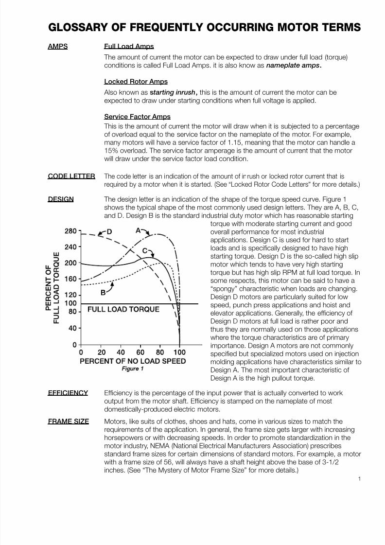
DESIGN The design letter is an indication of the shape of the torque speed curve. Figure 1shows the typical shape of the most commonly used design letters. They are A, B, C,and D. Design B is the standard industrial duty motor which has reasonable starting
torque with moderate starting current and goodoverall performance for most industrialapplications. Design C is used for hard to startloads and is specifically designed to have highstarting torque. Design D is the so-called high slipmotor which tends to have very high startingtorque but has high slip RPM at full load torque. Insome respects, this motor can be said to have a
“spongy” characteristic when loads are changing.Design D motors are particularly suited for lowspeed, punch press applications and hoist andelevator applications. Generally, the efficiency of Design D motors at full load is rather poor andthus they are normally used on those applicationswhere the torque characteristics are of primaryimportance. Design A motors are not commonlyspecified but specialized motors used on injectionmolding applications have characteristics similar toDesign A. The most important characteristic of Design A is the high pullout torque.
EFFICIENCY Efficiency is the percentage of the input power that is actually converted to work output from the motor shaft. Efficiency is stamped on the nameplate of mostdomestically-produced electric motors.
FRAME SIZE Motors, like suits of clothes, shoes and hats, come in various sizes to match therequirements of the application. In general, the frame size gets larger with increasinghorsepowers or with decreasing speeds. In order to promote standardization in themotor industry, NEMA (National Electrical Manufacturers Association) prescribesstandard frame sizes for certain dimensions of standard motors. For example, a motorwith a frame size of 56, will always have a shaft height above the base of 3-1/2inches. (See “ The Mystery of Motor Frame Size” for more details.)

8/20/2019 Elctric Motors BALDOR
http://slidepdf.com/reader/full/elctric-motors-baldor 8/124
2
FREQUENCY This is the frequency for which the motor is designed. The most commonly occurringfrequency in this country is 60 cycles but, on an international basis, other frequenciessuch as 40, and 50 cycles can be found.
FULL LOAD An indication of the approximate speed that the motor will run when it is putting outSPEED full rated output torque or horsepower is called full load speed.
HIGH INERTIA These are loads that have a relatively high flywheel effect. Large fans, blowers, punchLOAD presses, centrifuges, commercial washing machines, and other types of similar loads
can be classified as high inertia loads.
INSULATION The insulation class is a measure of the resistance of the insulating components of aCLASS motor to degradation from heat. Four major classifications of insulation are used in
motors. they are, in order of increasing thermal capabilities, A, B, F, and H. (See“Motor Temperature Rating” for more details.)
LOAD TYPES Constant Horsepower
The term constant horsepower is used in certain types of loads where the torquerequirement is reduced as the speed is increased and vice-versa. The constanthorsepower load is usually associated with metal removal applications such as drillpresses, lathes, milling machines, and other similar types of applications.
Constant Torque
Constant torque is a term used to define a load characteristic where the amount of torque required to drive the machine is constant regardless of the speed at which it isdriven. For example, the torque requirement of most conveyors is constant.
Variable Torque
Variable torque is found in loads having characteristics requiring low torque at lowspeeds and increasing values of torque as the speed is increased. Typical examples of variable torque loads are centrifugal fans and centrifugal pumps.
PHASEPhase is the indication of the type of power supply for which the motor is designed. Two major categories exist; single phase and three phase. There are some very spottyareas where two phase power is available but this is very insignificant.
POLES This is the number of magnetic poles that appear within the motor when power isapplied. Poles always come in sets of two (a north and a south). Thus, the number of poles within a motor is always an even number such as 2, 4, 6, 8, 10, etc. In an ACmotor, the number of poles work in conjunction with the frequency to determine thesynchronous speed of the motor. At 50 and 60 cycles, the common arrangements are:
Poles Synchronous Speed
60 Cycles 50 Cycles2 3600 3000
4 1800 1500
6 1200 1000
8 900 750
10 720 600
POWER Per cent power factor is a measure of a particular motor’s requirements forFACTOR magnetizing amperage.

8/20/2019 Elctric Motors BALDOR
http://slidepdf.com/reader/full/elctric-motors-baldor 9/124
3
SERVICE The service factor is a multiplier that indicates the amount of overload a motor can beFACTOR expected to handle. For example, a motor with a 1.0 service factor cannot be
expected to handle more than its nameplate horsepower on a continuous basis.Similarly, a motor with a 1.15 service factor can be expected to safely handleintermittent loads amounting to 15% beyond its nameplate horsepower.
SLIP Slip is used in two forms. One is the slip RPM which is the difference between thesynchronous speed and the full load speed. When this slip RPM is expressed as apercentage of the synchronous speed, then it is called percent slip or just “slip”. Moststandard motors run with a full load slip of 2% to 5%.
SYNCHRONOUS This is the speed at which the magnetic field within the motor is rotating. It is alsoSPEED approximately the speed that the motor will run under no load conditions. For
example, a 4 pole motor running on 60 cycles would have a magnetic field speed of 1800 RPM. The no load speed of that motor shaft would be very close to 1800,probably 1798 or 1799 RPM. the full load speed of the same motor might be 1745RPM. The difference between the synchronous speed and the full load speed is calledthe slip RPM of the motor.
TEMPERATURE Ambient Temperature
Ambient temperature is the maximum safe room temperature surrounding the motor if it is going to be operated continuously at full load. In most cases, the standardizedambient temperature rating is 40°C (104° F). This is a very warm room. Certain typesof applications such as on board ships and boiler rooms, may require motors with ahigher ambient temperature capability such as 50° C or 60° C.
Temperature Rise
Temperature rise is the amount of temperature change that can be expected withinthe winding of the motor from non-operating (cool condition) to its temperature at fullload continuous operating condition. Temperature rise is normally expressed indegrees centigrade.
TIME RATING Most motors are rated for continuous duty which means that they can operate at fullload torque continuously without overheating. Motors used on certain types of applications such as waste disposal, valve actuators, hoists, and other types of intermittent loads, will frequently be rated for short term duty such as 5 minutes, 15minutes, 30 minutes, or 1 hour. Just like a human being, a motor can be asked tohandle very strenuous work as long as it is not required on a continuous basis.
TORQUE Torque is the twisting force exerted by the shaft of a motor. Torque is measured inpound inches, pound feet, and on small motors, in terms of ounce inches. (For moreinformation see “Understanding Torque”.)
Full Load Torque
Full load torque is the rated continuous torque that the motor can support withoutoverheating within its time rating.
Peak Torque
Many types of loads such as reciprocating compressors have cycling torques wherethe amount of torque required varies depending on the position of the machine. Theactual maximum torque requirement at any point is called the peak torquerequirement. Peak torques are involved in things such as punch presses and othertypes of loads where an oscillating torque requirement occurs.

8/20/2019 Elctric Motors BALDOR
http://slidepdf.com/reader/full/elctric-motors-baldor 10/124
4
Pull Out Torque
Also known as breakdown torque, this is the maximum amount of torque that isavailable from the motor shaft when the motor is operating at full voltage and isrunning at full speed. The load is then increased until the maximum point is reached.Refer to figure 2.
Pull Up Torque
The lowest point on the torque speed curve for a motor that is accelerating a load upto full speed is called pull up torque. Some motor designs do not have a value of pullup torque because the lowest point may occur at the locked rotor point. In this case,pull up torque is the same as locked rotor torque.
Starting Torque
The amount of torque the motor produces when it is energized at full voltage and withthe shaft locked in place is called starting torque. This value is also frequentlyexpressed as “locked rotor torque”. It is the amount of torque available when power isapplied to break the load away and start accelerating it up to speed.
VOLTAGE This would be the voltage rating for which the motor is designed.

8/20/2019 Elctric Motors BALDOR
http://slidepdf.com/reader/full/elctric-motors-baldor 11/124
5
TYPES OF MOTORS
The most reliable piece of electrical equipment in service today is a transformer. The second most
reliable is the 3-phase induction motor. Properly applied and maintained, 3-phase motors will last many
years. One key element of motor longevity is proper cooling. Motors are generally classified by the
method used to dissipate the internal heat.
Several standard motor enclosures are availableto handle the range of applications from “cleanand dry” such as indoor air handlers, to the “wetor worse” as found on roofs and wet coolingtowers.
Open Drip-proof (ODP) motors are good forclean and dry environments. As the name implies,drip-proof motors can handle some drippingwater provided it falls from overhead or no morethan 15 degrees off vertical. These motors usuallyhave ventilating openings that face down. The
end housings can frequently be rotated tomaintain “drip-proof ” integrity when the motor ismounted in a different orientation. These motorsare cooled by a continuous flow of thesurrounding air through the internal parts of themotor.
Totally Enclosed Fan Cooled
(TEFC) motors are cooled byan external fan mounted onthe end opposite the shaft.
The fan blows ambient air
across the outside surface of the motor to carry heat away.
Air does not move through theinside of the motor, so TEFCmotors are suited for dirty,dusty, and outdoorapplications. there are manyspecial types of TEFC motors including CorrosionProtected and Washdown styles. These motorshave special features to handle difficultenvironments. TEFC motors generally have “weepholes” at their lowest points to prevent
condensation from puddling inside the motor. Asin open drip-proof motors, if the TEFC motor ismounted in a position other than horizontal, theend housings can generally be repositioned tokeep the weep holes at the lowest point.
Totally Enclosed Air Over (TEAO) motors areapplied in the air-stream on machines such asvane axial fans where the air moved by a directconnected fan passes over the motor and coolsit. TEAO motors frequently have dual HP ratings
depending on the speed and temperature of thecooling air. Typical ratings for a motor might be:10 HP with 750 feet per minute of 104°F air, 10HP with 400 FPM of 70°F air, or 12.5 HP with3000 FPM of 70°F air. TEAO motors are usuallyconfined to Original Equipment Manufacturer(OEM) applications because the air temperatureand flows need to be predetermined.
Totally Enclosed Non-ventilated (TENV) motorsare generally confined to small sizes (usuallyunder 5 HP) where the motor surface area is
large enough to radiate and convect the heat tothe outside air without an external fan or air flow. They have been popular in textile applicationsbecause lint cannot obstruct cooling.
Hazardous Location
Motors are a special form oftotally enclosed motor. Theyfall into different categoriesdepending upon theapplication and environment,as defined in Article 500 of
the National Electrical Code.
The two most commonhazardous location motorsare Class I, Explosion proof,and Class II, Dust IgnitionResistant. The term
explosion proof is commonly but erroneouslyused to refer to all categories of hazardouslocation motors. Explosion proof applies only toClass I environments, which are those that involvepotentially explosive liquids, vapors, and gases.
Class II is termed Dust Ignition Resistant. Thesemotors are used in environments that containcombustible dusts such as coal, grain, flour, etc.
Single Phase Motors
Three phase motors start and run in a directionbased on the “phase rotation” of the incomingpower. Single phase motors are different. Theyrequire an auxiliary starting means. Once startedin a direction, they continue to run in that

8/20/2019 Elctric Motors BALDOR
http://slidepdf.com/reader/full/elctric-motors-baldor 12/124
direction. Single phase motors are categorized bythe method used to start the motor and establishthe direction of rotation.
The three categories generally found in HVACapplications are:
Shaded pole is the simplest of all single phasestarting methods. These motors are used only forsmall, simple applications such as bathroom
exhaust fans. In the shaded pole motor, themotor field poles are notched and a coppershorting ring is installed around a small section of the poles as shown in Figure A-1.
The altered pole configuration delays themagnetic field build-up in the portion of the poles
surrounded by the copper shorting rings. Thisarrangement makes the magnetic field around therotor seem to rotate from the main pole towardthe shaded pole. This appearance of field rotationstarts the rotor moving. Once started, the motoraccelerates to full speed.
The split phase motor has two separatewindings in the stator (stationary portion of themotor). See Figure A-2. The winding shown in black
is only for starting. It uses a smaller wire size and has
higher electrical resistance than the main winding. The
difference in the start winding location and its altered
electrical characteristics causes a delay in current flow
between the two windings. This time delay coupled
with the physical location of the starting winding
causes the field around the rotor to move and
start the motor. A centrifugal switch or other
device disconnects the starting winding when the
motor reaches approximately 75% of rated
speed. The motor continues to run on normal
induction motor principles.
Split phase motors are generally available from1/25 to 1/2 HP. Their main advantage is low cost.
Their disadvantages are low starting torque and
high starting current. These disadvantages
generally limit split phase motors to applications
where the load needs only low starting torque and
starts are infrequent.
Capacitor motors are the most popular single
phase motors. They are used in many agricultural,
commercial and industrial applications where 3-phase
power is not available. Capacitor motors are available
in sizes from subfractional to 15 HP.
UsualCategory HP
Range
Capacitor start – induction run 1/8 - 3 HP
Single value capacitor 1/50 - 1 HP(also called permanent split capacitor or PSC)
Two-value capacitor 2 - 15 HP(also referred to as capacitor start capacitor run)
6
Approximate RelativeCategory
HP Range Efficiency
Shaded pole 1/100 - 1/6 HP Low
Split Phase 1/25 - 1/2 HP Medium
Medium toCapacitor 1/25 - 15 HP
High
Figure A-1: Shaded pole is the simplest of all single phase starting methods.
Figure A-2: The split-phase motor has two separate windings
in the stator.

8/20/2019 Elctric Motors BALDOR
http://slidepdf.com/reader/full/elctric-motors-baldor 13/124
7
Capacitor motors fall into three categories:
Capacitor Start Induction Run motors form the largest
group of general purpose single phase motors. The
winding and centrifugal switch arrangement is similar to
that in a split phase motor. However, a capacitor start
motor has a capacitor in series with the starting
winding. Figure A-3 shows the capacitor start motor.
The starting capacitor produces a time delay between
the magnetization of the starting poles and the running
poles, creating the appearance of a rotating field. The
rotor starts moving in the same direction. As the rotor
approaches running speed, the starting switch opens
and the motor continues to run in the normal induction
motor mode.
This moderately priced motor produces relatively high
starting torque (225 to 400% of full load torque) with
moderate inrush current. Capacitor start motors are
ideal for hard to start loads such as refrigerationcompressors. Due to its other desirable
characteristics, it is also used in applications where
high starting torque may not be required. The
capacitor start motor can usually be recognized by the
bulbous protrusion on the frame that houses the
starting capacitor.
In some applications it is not practical to install a
centrifugal switch within the motor. these motors have
a relay operated by motor inrush current. The relay
switches the starting capacitor into the circuit during
the starting period. When the motor approaches full
speed the inrush current decreases and the relay
opens to disconnect the starting capacitor.
Single Value Capacitor Motors, also called
permanent Split Capacitor (PSC) motors utilize a
capacitor connected in series with one of the two
windings. This type of motor is generally used on small
sizes (less than 1 HP). It is ideally suited for small fans,
blowers, and pumps. Starting torque on this type of
motor is generally 100%, or less, of full load torque.
Two Value Capacitor Motors. The two value
capacitor motor is utilized in large horsepower (5-15
HP) single phase motors. Figure A-4 shows this motor.
The running winding, shown in white, is energized
directly from the line. A second winding, shown in
black, serves as a combined starting and running
winding. The black winding is energized through twoparallel capacitors. Once the motor has started, a
switch disconnects one of the capacitors letting the
motor operate with the remaining capacitor in series
with the second winding of the motor.
The two value capacitor motor starts as a capacitor
start motor but runs as a form of a two phase or PSC
motor. Using this combination, it is possible to build
large single phase motors having high starting torques
and moderate starting currents at reasonable prices.
The two value capacitor motor frequently uses anoversize conduit box to house both the starting and
running capacitors.
Figure A-3: A capacitor start motor has a capacitor in series with
the starter winding.
Figure A-4: The two valve capacitor motor is used in large
horsepower single phase motors.
8/20/2019 Elctric Motors BALDOR
http://slidepdf.com/reader/full/elctric-motors-baldor 14/124
8
Motors Operating on Adjustable Frequency Drives
(AFDs) In the infancy of adjustable frequency drives
(AFDs), a major selling point was that AFDs could
adjust the speed of “standard” 3-phase induction
motors. This claim was quite true when the adjustable
frequency drives were “6-step” designs. The claim is
still somewhat true, although Pulse Width Modulated
(PWM) AFDs have somewhat changed the rules, PWM
drives are electrically more punishing on motor
windings, especially for 460 and 575 volt drives.
“Standard” motors can still be used on many AFDs,
especially on HVAC fan, blower, and pump
applications, as long as the motors are high quality,
conservative designs. On these variable torque loads a
relatively small speed reduction results in a dramatic
reduction in the torque required from the motor. For
example, a 15% reduction in speed reduces the
torque requirement by over 25%, so these motors are
not stressed from a thermal point of view. Also,
variable torque loads rarely need a wide speed range.Since the performance of pumps, fans, and blowers
falls off dramatically as speed is reduced, speed
reduction below 40% of base speed is rarely required.
The natural question is, “What is meant by a high
quality, conservative designs?” Basically, this means
that the motor must have phase insulation, should
operate at a relatively low temperature rise (as in the
case with most premium efficiency motors), and
should use a high class of insulation (either F or H).
In addition, it is frequently desirable to have a windingthermostat in the motor that will detect any motor
overheat conditions that may occur. Overheating could
result from overload, high ambient temperature, or loss
of ventilation.
“Inverter Duty Motors” being offered in the
marketplace today incorporate “premium efficiency”
designs along with oversized frames or external
blowers to cool the motor regardless of its speed.
These motors are primarily designed for constant
torque loads where the affinity laws do not apply.
“Inverter Duty Motors” usually have windingthermostats that shut the motor down through the
AFD control circuit in case of elevated temperature
inside the motor. Inverter Duty Motors also have high
temperature insulating materials operated at lower
temperatures. This reduces the stress on the insulation
system. Although some of the design features of
inverter duty motors are desirable for HVAC
applications, HVAC applications usually do not require
“inverter duty” motors.
Some cautions should be observed. Generally
speaking, the power coming out of an AFD is
somewhat rougher on the motor than power from a
pure 60 cycle source. Thus it is not a good idea to
operate motors on AFDs into their service factors.
In addition, when an old motor (one that has been in
service for some time) is to be repowered from an
adjustable frequency drive, it may be desirable to add
a load reactor between the AFD and the motor. The
reactor reduces the stress on the motor windings by
smoothing out current variations, thereby prolonging
motor life.
Reactors are similar to transformers with copper coils
wound around a magnetic core. Load reactors
increase in importance when the AFDs are going to
run in the “quiet” mode. In this mode the very high
carrier frequency can create standing waves that
potentially double the voltage peaks applied to the
motor. The higher voltage can stress the motorinsulation enough to cause premature failure.
Service Factor
Some motors carry a service factor other than 1.0.
This means the motor can handle loads above the
rated HP. A motor with a 1.15 service factor can
handle a 15% overload, so a 10 HP motor with a 1.15
service factor can handle 11.5 HP of load. Standard
open drip-proof motors have a 1.15 service factor.
Standard TEFC motors have a 1.0 service factor, but
most major motor manufacturers now provide TEFCmotors with a 1.15 service factor.
The question often arises whether to use service factor
in motor load calculations. In general, the best answer
is that for good motor longevity, service factor should
not be used for basic load calculations. By not loading
the motor into the service factor, the motor can better
withstand adverse conditions that occur. Adverse
conditions include higher than normal ambient
temperatures, low or high voltage, voltage imbalances,
and occasional overload. These conditions are less
likely to damage the motor or shorten its life if themotor is not loaded into its service factor in normal
operation.
NEMA Locked Rotor Code
The “NEMA Code Letter” is an additional piece of
information on the motor nameplate. These letters
indicate a range of inrush (starting – or “locked rotor” )
currents that occur when a motor starts across the
line with a standard magnetic or manual starter. Most

8/20/2019 Elctric Motors BALDOR
http://slidepdf.com/reader/full/elctric-motors-baldor 15/124
9
motors draw 5 to 7 times rated full load (nameplate)
amps during the time it takes to go from standstill up
to about 80% of full load speed. The length of time the
inrush current lasts depends on the amount of inertia
(flywheel effect) in the load. On centrifugal pumps with
very low inertia, the inrush current lasts only a few
seconds. On large, squirrel cage blowers the inrush
current can last considerably longer.
The locked rotor code letter quantifies the value of the
inrush current for a specific motor. The lower the code
letter, the lower the inrush current. Higher code letters
indicate higher inrush currents.
The table lists the NEMA locked rotor code letters and
their parameters:
The code letters usually applied to common motors
are:
The proposed Design E motors, which will have very
high efficiencies, will have higher inrush currents than
the motors currently available. These motors will
require special considerations when sizing circuit
breakers and starters for these motors when they
become available. The 1998 National Electrical Code
incorporated some special provisions for these
proposed Design E motors.
Insulation Classes
The electrical portions of every motor must be
insulated from contact with other wires and with the
magnetic portion of the motor. The insulation system
consists of the varnish that jackets the magnet wire in
the windings along with the slot liners that insulate the
wire from the steel laminations. The insulation system
also includes tapes, sleeving, tie strings, a final dippingvarnish, and the leads that bring the electrical circuits
out to the junction box.
Insulation systems are rated by their resistance to
thermal degradation. The four basic insulation systems
normally encountered are Class A, B, F, and H. Class
A has a temperature rating of 105°C (221°F), and
each step from A to B, B to F, and F to H involves a
25°C (45°F) jump. The insulation class in any motor
must be able to withstand at least the maximum
ambient temperature plus the temperature rise that
occurs as a result of continuous full load operation.
Selecting an insulation class higher than necessary to
meet this minimum can help extend motor life or make
a motor more tolerant of overloads, high ambient
temperatures, and other problems that normally
shorten motor life.
A widely used rule of thumb states that every 10°C
(18°F) increase in operating temperature cuts
insulation life in half. Conversely, a 10°C decrease
doubles insulation life. Choosing a one step higher
insulation class than required to meet the basicperformance specifications of a motor provides 25°C
of extra temperature capability. The rule of thumb
predicts that this better insulation system increases
the motor’s thermal life expectancy by approximately
500%.
Motor Design Letters
The National Electrical Manufacturer’s Association
(NEMA) has defined four standard motor designs
using the letters A, B, C and D. These letters refer to
the shape of the motors’ torque and inrush current vs.
speed curves. Design B is the most popular motor. It
has a relatively high starting torque with reasonable
starting currents. The other designs are only used on
fairly specialized applications. Design A is frequently
used on injection molding machines that require high
pullout torques. Design C is a high starting torque
motor that is usually confined to hard to start loads,
such as conveyors that are going to operate under
difficult conditions.
F G H J K L
3phase 15 up 10 - 71 / 2 5 3 2 - 11 / 2 1
HP
1phase 5 3 2 - 11 / 2 1, 3 / 4 1 / 2
HP
NEMA Locked NEMA Locked
Code Rotor Code Rotor
Letter KVA/HP Letter KVA/HP
A 0 - 3.15 L 9.0 - 10.0B 3.15 - 3.55 M 10.0 - 11.2
C 3.55 - 4.0 N 11.2 - 12.5
D 4.0 - 4.5 0 not used
E 4.5 - 5.0 P 12.5 - 14.0
F 5.0 - 5.6 Q not used
G 5.6 - 6.3 R 14.0 - 16.0
H 6.3 - 7.1 S 16.0 - 18.0
I not used T 18.0 - 20.0
J 7.1 - 8.0 U 20.0 - 22.4
K 8.0 - 9.0 V 22.4 and up

8/20/2019 Elctric Motors BALDOR
http://slidepdf.com/reader/full/elctric-motors-baldor 16/124
10
Design D is a so-called high slip motor and is normally
limited to applications such as cranes, hoists, and low
speed punch presses where high starting torque with
low starting current is desirable. Design B motors do
very well on most HVAC applications.

8/20/2019 Elctric Motors BALDOR
http://slidepdf.com/reader/full/elctric-motors-baldor 17/124
11
THE MYSTERY OF MOTOR FRAME SIZE
INTRODUCTION
Industrial electric motors have been available for nearly a century. In that time there have been a greatmany changes. One of the most obvious has been the ability to pack more horsepower in a smallerphysical size. Another important achievement has been the standardization of motors by the NationalElectric Manufacturers Association (NEMA).
A key part of motor interchangeability has been the standardization of frame sizes. This means that thesame horsepower, speed, and enclosure will normally have the same frame size from different motormanufacturers. Thus, a motor from one manufacturer can be replaced with a similar motor from anothercompany provided they are both in standard frame sizes.
THREE GENERATIONS
The standardization effort over the last forty years has resulted in one original grouping of frame sizescalled “original”. In 1952, new frame assignments were made. These were called “U frames”. The current“ T frames” were introduced in 1964. “ T ” frames are the current standard and most likely will continue tobe for some time in the future.
Even though “ T ” frames were adopted in 1964, there are still a great many “U” frame motors in service
that will have to be replaced in the future. Similarly there are also many of the original frame size motors(pre-1952) that will reach the end of their useful life and will have to be replaced. For this reason, it isdesirable to have reference material available on frame sizes and some knowledge of changes that took place as a part of the so-called rerate programs.
FRAME SIZE REFERENCE TABLES
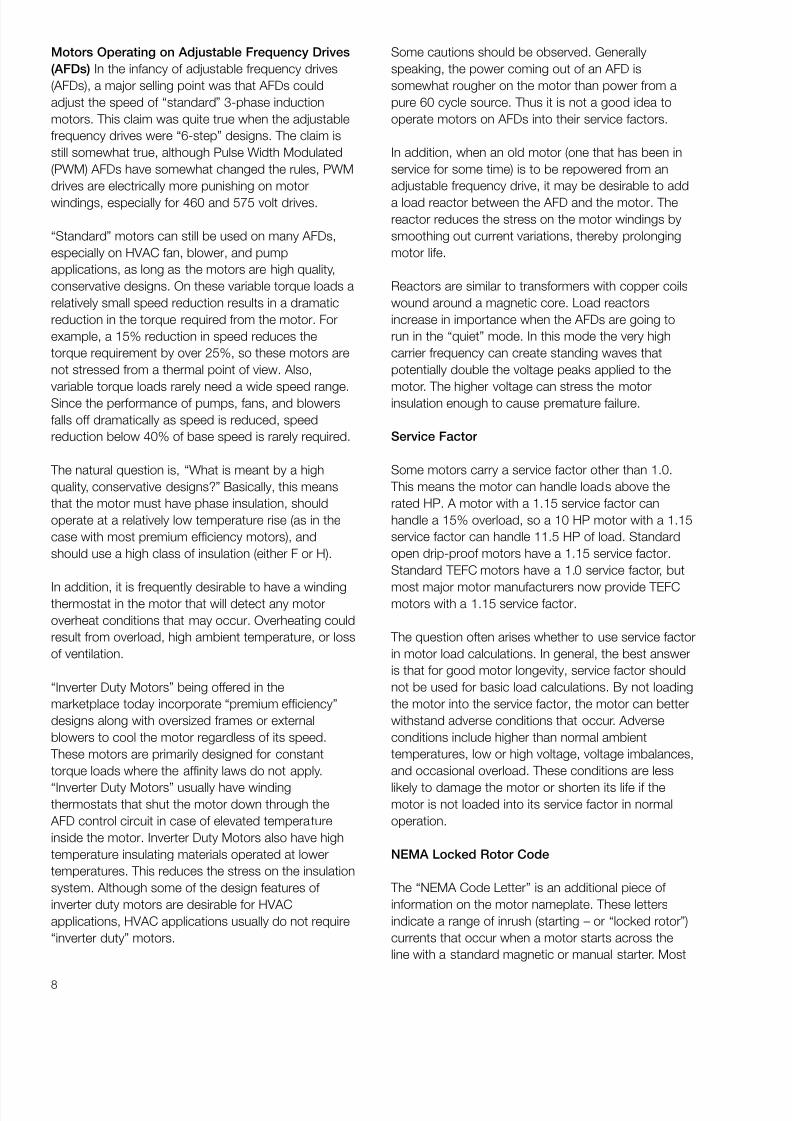
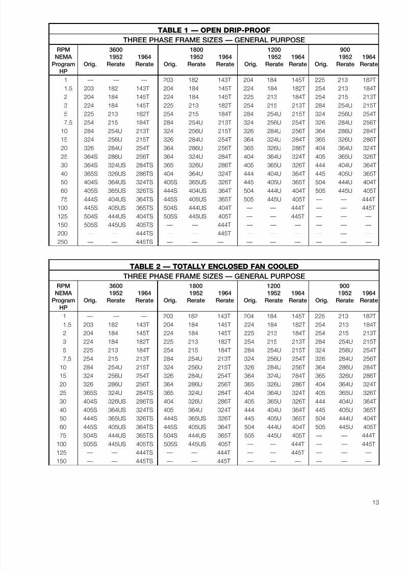
Tables 1 and 2 show the standard frame size assignments for the three different eras of motors. As youwill note, these tables are broken down for open drip proof (table 1) and totally enclosed (table 2). Also,you will find that for each horsepower rating and speed, there are three different frame sizes. The first isthe original frame size, the middle one is the “U frame” size, and the third one is the “ T frame”. These arehandy reference tables since they give general information for all three vintages of three phase motors inintegral horsepower frame sizes.
One important item to remember is that the base mounting hole spacing (“E” and “F” dimensions) andshaft height (“D” dimension) for all frames having the same three digits regardless of vintage, will be thesame.
RERATING AND TEMPERATURES
The ability to rerate motor frames to get more horsepower in a frame has been brought about mainly byimprovements made in insulating materials. As a result of this improved insulation, motors can be runmuch hotter. This allows more horsepower in a compact frame. For example, the original NEMA framesizes ran at very low temperatures. The “U” frame motors were designed for use with Class A insulation,which has a rating of 105° C. The motor designs were such that the capability would be used at thehottest spot within the motor. “ T ” frame motor designs are based on utilizing Class B insulation with a
temperature rating of 130° C. This increase in temperature capability made it possible to pack morehorsepower into the same size frame. To accommodate the larger mechanical horsepower capability,shaft and bearing sizes had to be increased. Thus, you will find that the original 254 frame (5 HP at 1800RPM) has a 1-1/8" shaft. The 254U frame (7-1/2 HP at 1800 RPM) has a 1-3/8" shaft, and the current254T frame (15 HP at 1800 RPM) has a 1-5/8" shaft. Bearing diameters were also increased toaccommodate the larger shaft sizes and heavier loads associated with the higher horsepowers.
FRAME SIZE BASIS
On page 14 you will find a Baldor frame size chart that is a great reference on “ T ” frame, “U” frame andoriginal frame motors. Most of the dimensions are standard dimensions that are common to all motormanufacturers.

8/20/2019 Elctric Motors BALDOR
http://slidepdf.com/reader/full/elctric-motors-baldor 18/124
12
FRACTIONAL HORSEPOWER MOTORS
The term “fractional horsepower” is used to cover those frame sizes having two digit designations asopposed to the three digit designations that are found in Tables 1 and 2. The frame sizes that are normallyassociated with industrial fractional horsepower motors are 42, 48, and 56. In this case, each frame sizedesignates a particular shaft height, shaft diameter, and face or base mounting hole pattern. In thesemotors, specific frame assignments have not been made by horsepower and speed, so it is possible that aparticular horsepower and speed combination might be found in three different frame sizes. In this case, forreplacement it is essential that the frame size be known as well as the horsepower, speed and enclosure.
The derivation of the two digit frame number is based on the shaft height in sixteenths of an inch. You canfigure that a 48 frame motor will have a shaft height of 48 divided by 16 or 3 inches. Similarly, a 56 framemotor would have a shaft height of 3-1/2 inches. The largest of the current fractional horsepower framesizes is a 56 frame which is available in horsepowers greater than those normally associated withfractionals. For example, 56 frame motors are built in horsepowers up to 3 HP and in some cases, 5 HP.For this reason, calling motors with 2 digit frame sizes “fractionals” is somewhat misleading.
INTEGRAL HORSEPOWER MOTORS
The term Integral Horsepower Motors generally refers to those motors having three digit frame sizes suchas 143T or larger. When dealing with these frame sizes one “rule of thumb” is handy. It is that the centerlineshaft height (“D” dimension) above the bottom of the base is the first two digits of the frame size divided byfour. For example, a 254T frame would have a shaft height of 25 ÷ 4 = 6.25 inches. Although the last digit
does not directly relate to an “inch” dimension, larger numbers do indicate that the rear bolt holes aremoved further away from the shaft end bolt holes (the “F” dimension becomes larger).
VARIATIONS
In addition to the standard numbering system for frames, there are some variations that will appear. These are itemized below along with an explanation of what the various letters represent.
C — Designates a “C” face (flange) mounted motor. This is the most popular type of face mounted motor andhas a specific bolt pattern on the shaft end to allow mounting. The critical items on “C” face motors arethe “bolt circle” (AJ dimension), register (also called rabbet) diameter (AK dimension) and the shaft size(U dimension). C flange motors always have threaded mounting holes in the face of the motor.
D — The “D” flange has a special type of mounting flange installed on the shaft end. In the case of the “D”flange, the flange diameter is larger than the body of the motor and it has clearance holes suitable formounting bolts to pass through from the back of the motor into threaded holes in the mating part. “D”flange motors are not as popular as “C” flange motors.
H — Used on some 56 frame motors, “H” indicates that the base is suitable for mounting in either 56, 143T, or145T mounting dimensions.
J — This designation is used with 56 frame motors and indicates that the motor is made for “ jet pump” servicewith a threaded stainless steel shaft and standard 56C face.
JM — The letters “JM” designate a special pump shaft originally designed for a “mechanical seal”. This motor alsohas a C face.
JP — Similar to the JM style of motor having a special shaft, the JP motor was originally designed for a “packing”type of seal. The motor also has a C face.
S — The use of the letter “S” in a motor frame designates that the motor has a “short shaft”. Short shaft motors
have shaft dimensions that are smaller than the shafts associated with the normal frame size. short shaftmotors are designed to be directly coupled to a load through a flexible coupling. They are not supposed tobe used on applications where belts are used to drive the load.
T — A “ T ” at the end of the frame size indicates that the motor is of the 1964 and later “ T ” frame vintage.
U — A “U” at the end of the frame size indicates that the motor falls into the “U” frame size assignment (1952 to1964) era.
Y — When a “ Y ” appears as a part of the frame size it means that the motor has a special mounting
configuration. It is impossible to tell exactly what the special configuration is but it does denote that there isa special non-standard mounting.
Z — Indicates the existence of a special shaft which could be longer, larger, or have special features such asthreads, holes, etc. “Z” indicates only that the shaft is special in some undefined way.
8/20/2019 Elctric Motors BALDOR
http://slidepdf.com/reader/full/elctric-motors-baldor 19/124
TABLE 2 — TOTALLY ENCLOSED FAN COOLED
THREE PHASE FRAME SIZES — GENERAL PURPOSE
RPM 3600 1800 1200 900
NEMA 1952 1964 1952 1964 1952 1964 1952 1964
Program Orig. Rerate Rerate Orig. Rerate Rerate Orig. Rerate Rerate Orig. Rerate RerateHP
1 — — — 203 182 143T 204 184 145T 225 213 182T
1.5 203 182 143T 204 184 145T 224 184 182T 254 213 184T
2 204 184 145T 224 184 145T 225 213 184T 254 215 213T
3 224 184 182T 225 213 182T 254 215 213T 284 254U 215T
5 225 213 184T 254 215 184T 284 254U 215T 324 256U 254T
7.5 254 215 213T 284 254U 213T 324 256U 254T 326 284U 256T
10 284 254U 215T 324 256U 215T 326 284U 256T 364 286U 284T
15 324 256U 254T 326 284U 254T 364 324U 284T 365 326U 286T
20 326 286U 256T 364 286U 256T 365 326U 286T 404 364U 324T
25 365S 324U 284TS 365 324U 284T 404 364U 324T 405 365U 326T
30 404S 326US 286TS 404 326U 286T 405 365U 326T 444 404U 364T40 405S 364US 324TS 405 364U 324T 444 404U 364T 445 405U 365T
50 444S 365US 326TS 444S 365US 326T 445 405U 365T 504 444U 404T
60 445S 405US 364TS 445S 405US 364T 504 444U 404T 505 445U 405T
75 504S 444US 365TS 504S 444US 365T 505 445U 405T — — 444T
100 505S 445US 405TS 505S 445US 405T — — 444T — — 445T
125 — — 444TS — — 444T — — 445T — — —
150 — — 445TS — — 445T — — — — — —
13
TABLE 1 — OPEN DRIP-PROOF
THREE PHASE FRAME SIZES — GENERAL PURPOSE
RPM 3600 1800 1200 900
NEMA 1952 1964 1952 1964 1952 1964 1952 1964
Program Orig. Rerate Rerate Orig. Rerate Rerate Orig. Rerate Rerate Orig. Rerate Rerate
HP
1 — — — 203 182 143T 204 184 145T 225 213 182T
1.5 203 182 143T 204 184 145T 224 184 182T 254 213 184T
2 204 184 145T 224 184 145T 225 213 184T 254 215 213T
3 224 184 145T 225 213 182T 254 215 213T 284 254U 215T
5 225 213 182T 254 215 184T 284 254U 215T 324 256U 254T
7.5 254 215 184T 284 254U 213T 324 256U 254T 326 284U 256T
10 284 254U 213T 324 256U 215T 326 284U 256T 364 286U 284T
15 324 256U 215T 326 284U 254T 364 324U 284T 365 326U 286T
20 326 284U 254T 364 286U 256T 365 326U 286T 404 364U 324T
25 364S 286U 256T 364 324U 284T 404 364U 324T 405 365U 326T
30 364S 324US 284TS 365 326U 286T 405 365U 326T 444 404U 364T
40 365S 326US 286TS 404 364U 324T 444 404U 364T 445 405U 365T
50 404S 364US 324TS 405S 365US 326T 445 405U 365T 504 444U 404T
60 405S 365US 326TS 444S 404US 364T 504 444U 404T 505 445U 405T
75 444S 404US 364TS 445S 405US 365T 505 445U 405T — — 444T 100 445S 405US 365TS 504S 444US 404T — — 444T — — 445T
125 504S 444US 404TS 505S 445US 405T — — 445T — — —
150 505S 445US 405TS — — 444T — — — — — —
200 — — 444TS — — 445T — — — — — —
250 — — 445TS — — — — — — — — —

8/20/2019 Elctric Motors BALDOR
http://slidepdf.com/reader/full/elctric-motors-baldor 20/124
14
NEMA FRAMES PRIOR TO 1953
FRAME D E F N U V BA
66 4-1/8 2-15 /16 2-1 /2 2-1/4 3/ 4 2-1/4 3-1/8
203 5 4 2-3/4 2-7/16 3/4 2 3-1/8204 3-1/4
224 5 -1 /2 4 -1 /2 3-3/8 3-1/4 1 3 3-1/2225 3-3/4
254 6-1/4 5 4-1/8 3-7/16 1-1/8 3-3/8 4-1/4
284 7 5-1/2 4-3/4 4-1/4 1-1/4 3-3/4 4-3/4
324 8 6-1/4 5-1/4 5 -3 /8 1 -5 /8 4 -7 /8 5 -1 /4326 6
364 9 7 5-5/8 5 -5 /8 1 -7 8/ 8 5 -3 /8 5 -7 /8365 6-1/8
404 10 8 6-1/8 6 -3 /8 2 -1 /8 6 -1 /8 6 -5 /8405 6-7/8
444 11 9 7-1/4 7 -1 /8 2 -3 /8 6 -7 /8 7 -1 /2445 8-1/4
504 12-1/ 2 10 8 8 -5 /8 2 -7 /8 8 -3 /8 8 -1 /2505 9
5000
FRAME D E 2F H O P U V AA AB BA
5007S 12-1/2 10 22 15/16 26-27/32 30 2-1/2 6-1/2 4-NPT 26-7/8 8-1/2
5007L 12-1/2 10 22 15/16 26-27/32 30 3-7/8 11-1/8 4-NPT 26-7/8 8-1/2
5009S 12-1/2 10 28 15/16 26-27/32 30 2-1/2 6-1/2 4-NPT 26-7/8 8-1/2
5009L 12-1/2 10 28 15/16 26-27/32 30 3-7/8 11-1/8 4-NPT 26-7/8 8-1/2
5011S 12-1/2 10 36 15/16 26-27/32 30 2-1/2 6-1/2 4-NPT 26-7/8 8-1/2
5011L 12-1/2 10 36 15/16 26-27/32 30 3-7/8 11-1/8 4-NPT 26-7/8 8-1/2
NEMA -- QUICK REFERENCE CHART* CONTACT YOUR LOCAL BALDOR
OFFICE FOR "C" DIMENSIONS
DIMENSIONS - N, O, P, AB AND XO
ARE SPECIFIC TO BALDOR
BALDOR ELECTRIC COMPANY
P.O. BOX 2400
FORT SMITH, ARKANSAS
72902-2400 U.S.A.
NEMA
FRAME D E 2F H N O P U V AA AB AH AJ AK BA BB BD XO TAP
42 2-5/8 1-3/4 1-11/16 9/32 1-1/2 5 4-11/16 3/8 1-1/8 3/8 4-1/32 1-5/16 3-3/4 3 2-1/16 1/8 4-5/8 1-9/16 1/4-20SLOT
48 3 2-1/8 2-3/4 11/32 1-7/8 5-7/8 5-11/16 1/2 1-1/2 1/2 4-3/8 1-11/16 3-3/4 3 2-1/2 1/8 5-5/8 2-1/4 1/4-20SLOT
56 3-1/2 2-7/16 3 11/32 2-7/16 6 -7/8 6-5/8 5/8 1-7/8 1 /2 5 2-1/16 5-7/8 4-1/2 2-3/4 1/8 6-1/2 2-1/4 3 /8-1656H 5 SLOT 2-1/8
143T 3-1/2 2-3/4 4 11/32 2-1/2 6-7/8 6-5/8 7/8 2-1/4 3/4 5-1/4 2-1/8 5-7/8 4-1/2 2-1/4 1/8 6-1/2 2-1/4 3/8-16145T 5
182 4-1/2 2-11/16 7/8 2-1/4 2-1/8 5-7/8 4-1/2 1/8 6-1/2 3/8-16
184 4-1/2 3-3/4 5-1/2 13/32 2-11/16 8-11/16 7-7/8 7/8 2-1/4 3/4 5-7/8 2-1/8 5-7/8 4-1/2 2-3/4 1/8 6-1/2 2-3/8 3/8-16
182T 4-1/2 3-9/16 1-1/8 2-3/4 2-5/8 7-1/4 8-1/2 1/4 9 1/2-13
184T 5-1/2 3-9/16 1-1/8 2-3/4 2-5/8 7-1/4 8-1/2 1/4 9 1/2-13
213 5-1/2 3-1/2 1-1/8 3 2-3/4
215 5-1/4 4-1/4 7 13/32 3-1/2 10-1/4 9-9/16 1-1/8 3 3/4 7-3/8 2-3/4 7-1/4 8-1/2 3-1/2 1/4 9 2-3/4 1/2-13213T 5-1/2 3-7/8 1-3/8 3-3/8 3-1/8
215T 7 3-7/8 1-3/8 3-3/8 3-1/8
254U 8-1/4 4-1/16 1-3/8 3-3/4 3-1/2
256U 6-1/4 5 10 17/32 4-1/16 12-7/8 12-15/16 1-3/8 3-3/4 1 9-5/8 3-1/2 7-1/4 8-1/2 4-1/4 1 /4 10 --- 1/2-13254T 8-1/4 4-5/16 1-5/8 4 3-3/4
256T 10 4-5/16 1-5/8 4 3-3/4
284U 9-1/2 5-1/8 1-5/8 4-7/8 4-5/8
286U 11 5-1/8 1-5/8 4-7/8 4-5/8
284T 7 5-1/2 9-1/2 17/32 4-7/8 14-5/8 14-5/8 1-7/8 4-5/8 1-1/2 13-1/8 4-3/8 9 10-1/2 4-3/4 1/4 11-1/4 - -- 1/2-13286T 11 4-7/8 1-7/8 4-5/8 4-3/8
284TS 9-1/2 3-3/8 1-5/8 3-1/4 3
286TS 11 3-3/8 1-5/8 3-1/4 3
324U 10-1/2 5-7/8 1-7/8 5-5/8 5-3/8
326U 12 5-7/8 1-7/8 5-5/8 5-3/8
324T 8 6-1/4 10-1/2 21/32 5-1/2 16-1/2 16-1/2 2-1/8 5-1/4 2 14-1/8 5 11 12-1/2 5-1/4 1/4 13-3/8 --- 5/8-11326T 12 5-1/2 2-1/8 5-1/4 5
324TS 10-1/2 3-15/16 1-7/8 3-3/4 3-1/2
326TS 12 3-15/16 1-7/8 3-3/4 3-1/2
364U 11-1/4 6-3/4 2-1/8 6-3/8 6-1/8
365U 12-1/4 6-3/4 2-1/8 6-3/8 6-1/8
364T 9 7 11-1/4 21/32 6-1/4 18-1/2 18-1/4 2-3/8 5-7/8 2-1/2 15-1/16 5-5/8 11 12-1/2 5-7/8 1/4 13-3/8 --- 5/8-11365T 12-1/4 6-1/4 2-3/8 5-7/8 5-5/8
364TS 11-1/4 4 1-7/8 3-3/4 3-1/2
365TS 12-1/4 4 1-7/8 3-3/4 3-1/2
404U 12-1/4 7-3/16 2-3/8 7-1/8 6-7/8
405U 13-3/4 7-3/16 2-3/8 7-1/8 6-7/8
404T 10 8 12-1/4 13/16 7-5/16 20-5/16 20-1/8 2-7/8 7-1/4 3 18 7 11 12-1/2 6-5/8 1/4 13-7/8 --- 5/8-11405T 13-3/4 7-5/16 2-7/8 7-1/4 7
404TS 12-1/4 4-1/2 2-1/8 4-1/4 4
405TS 13-3/4 4-1/2 2-1/8 4-1/4 4
444U 14-1/2 8-5/8 22-7/8 22-3/8 2-7/8 8-5/8 19-9/16 8-3/8
445U 16-1/2 8-5/8 22-7/8 22-3/8 2-7/8 8-5/8 19-9/16 8-3/8
444T 14-1/2 8-1/2 22-7/8 22-3/8 3-3/8 8-1/2 19-9/16 8-1/4
445T 16-1/2 8-1/2 22-7/8 22-3/8 3-3/8 8-1/2 19-9/16 8-1/4
447T 11 9 20 13/16 8-15/16 22-15/16 23-3/4 3-3/8 8-1/2 3 21-11/16 8-1/4 14 16 7-1/2 1 /4 16-3/4 --- 5/8-11449T 25 8-15/16 22-15/16 23-3/4 3-3/8 8-1/2 21-11/16 8-1/4
444TS 14-1/2 5-3/16 22-7/8 22-3/8 2-3/8 4-3/4 19-9/16 4-1/2
445TS 16-1/2 5-3/16 22-7/8 22-3/8 2-3/8 4-3/4 19-9/16 4-1/2
447TS 20 4-15/16 22-15/16 23-3/4 2-3/8 4-3/4 4NPT 21-11/16 4-1/2
449TS 25 4-15/16 22-15/16 23-3/4 2-3/8 4-3/4 4NPT 21-11/16 4-1/2
NEMA C-FACE BA DIMENSIONS
143-5TC 2-3/4
182-4TC 3-1/2
213-5TC 4-1/4
254-6TC 4-3/4
Drawings represent standard TEFC general purpose motors.
*Dimensions are for reference only.
SHAFT DIMENSIONS SHAFT D
Leader in Energy Efficient
Industrial Electric Motors and Drives
NEMA KEYSEAT NEMA KEYSEAT
SHAFT DIMENSIONS SHAFT DIMENSIONS
(U) (R) (S) (U) (R) (S)
3/8 21/64 FLAT 1-7/8 1-19/32 1/2
1/2 29/64 FLAT 2-1/8 1-27/32 1/25/8 33/64 3/16 2-3/8 2-1/64 5/8
7/8 49/64 3/16 2-1/2 2-3/16 5/8
1-1/8 63/64 1/4 2-7/8 2-29/64 3/4
1-3/8 1-13/64 5/16 3-3/8 2-7/8 7/8
1-5/8 1-13/32 3/8 3-7/8 3-5/16 1
S
U
R

8/20/2019 Elctric Motors BALDOR
http://slidepdf.com/reader/full/elctric-motors-baldor 21/124
15
A PRIMER ON TWO SPEED MOTORS
There seems to be a lot of mystery involved in two speed motors but they are really quite simple. Theycan first be divided into two different winding types:
TWO SPEED, TWO WINDING
The two winding motor is made in such a manner that it is really two motors wound into one stator. Onewinding, when energized, gives one of the speeds. When the second winding is energized, the motortakes on the speed that is determined by the second winding. The two speed, two winding motor canbe used to get virtually any combination of normal motor speeds and the two different speeds need notbe related to each other by a 2:1 speed factor. Thus, a two speed motor requiring 1750 RPM and 1140RPM would, of necessity, have to be a two winding motor.
TWO SPEED, ONE WINDING
The second type of motor is the two speed, single winding motor. In this type of motor, a 2:1 relationshipbetween the low and high speed must exist. Two speed, single winding motors are of the design that iscalled consequent pole. These motors are wound for one speed but when the winding is reconnected,the number of magnetic poles within the stator is doubled and the motor speed is reduced to one-half of the original speed. The two speed, one winding motor is, by nature, more economical to manufacturethan the two speed, two winding motor. This is because the same winding is used for both speeds andthe slots in which the conductors are placed within the motor do not have to be nearly as large as theywould have to be to accommodate two separate windings that work independently. Thus, the frame sizeon the two speed, single winding motor can usually be smaller than on an equivalent two winding motor.
LOAD CLASSIFICATION
A second item that generates a good deal of confusion in selecting two speed motors is the loadclassification for which these motors are to be used. In this case, the type of load to be driven must bedefined and the motor is selected to match the load requirement.
The three types that are available are: Constant Torque, Variable Torque, and Constant Horsepower.
For more details on load types please refer to “Understanding Torque” in this booklet.
CONSTANT TORQUE
Constant torque loads are those types of loads where the torque requirement is independent of speed.this type of load is the normally occurring load on such things as conveyors, positive displacementpumps, extruders, hydraulic pumps, packaging machinery, and other similar types of loads.
VARIABLE TORQUE
A second load type that is very different from Constant Torque is the kind of load presented to a motor
by centrifugal pumps and blowers. In this case, the load torque requirement changes from a low value atlow speed to a very high value at high speed. On a typical variable torque load, doubling the speed willincrease the torque requirement by 4 times and the horsepower requirement by 8 times. Thus, on thistype load, brute force must be supplied at the high speed and much reduced levels of horsepower andtorque are required at the low speed. A typical two speed, variable torque motor might have a rating of 1HP at 1725 and .25 HP at 850 RPM.
The characteristics of many pumps, fans, and blowers are such that a speed reduction to one-half results in an output at the low speed which may be unacceptable. Thus, many two speed, variabletorque motors are made with a speed combination of 1725/1140 RPM. This combination gives an outputfrom the fan or pump of roughly one-half when the low speed is utilized.

8/20/2019 Elctric Motors BALDOR
http://slidepdf.com/reader/full/elctric-motors-baldor 22/124
16
CONSTANT HORSEPOWER
The final type of two speed motor that is utilized is the two speed, constant horsepower motor. In thiscase, the motor is designed so that the horsepower stays constant when the speed is reduced to thelow value. In order to do this, it is necessary for the motor’s torque to double when it is operating in thelow speed mode. The normal application for this type of motor is on metal working processes such asdrill presses, lathes, milling machines, and other similar metal removing machines.
The requirement for constant horsepower can perhaps be best visualized when you consider the
requirements of a simple machine like a drill press. In this case, when drilling a large hole with a large drill,the speed is low but the torque requirement is very high. Compare that to the opposite extreme of drillinga small hole when the drill speed must be high but the torque requirement is low. Thus, there is arequirement for torque to be high when speed is low and torque to be low when speed is high. This isthe Constant Horsepower situation.
The Constant Horsepower motor is the most expensive two speed motor. Three phase, two speedmotors are quite readily available in constant torque and variable torque. Two speed, constanthorsepower motors are usually only available on a special order basis.
TWO SPEED, SINGLE PHASE MOTORS
Two speed, single phase motors for constant torque requirements are more difficult to supply since thereis a problem of providing a starting switch that will operate at the proper time for both speeds. Thus, thenormal two speed, single phase motor is offered as a variable torque motor in a permanent splitcapacitor configuration. The permanent split capacitor motor has very low starting torque but is suitablefor use on small centrifugal pumps and fans.
SUMMARY
The use of two speed motors in the future will grow quite rapidly as industrial motor users begin to realizethe desirability of using this type of motor on exhaust fans and circulating pumps so that the air flow andwater flow can be optimized to suit the conditions that exist in a plant or a process. Very dramaticsavings in energy can be achieved by utilizing the two speed approach.

8/20/2019 Elctric Motors BALDOR
http://slidepdf.com/reader/full/elctric-motors-baldor 23/124
MOTOR TEMPERATURE RATINGS
A frequently misunderstood subject related to electric motors is insulation class and temperature ratings. This paper tries to describe, in basic terms, the temperature relationships that are meaningful in standard AC induction motors. Some of the same information can be applied to DC motors but DC motors aremore specialized and some of the ratings are slightly different.
Perhaps the best way to start is to define the commonly used terms.
DEFINITIONS
AMBIENT TEMPERATURE
Ambient temperature is the temperature of the air surrounding the motor or the room temperaturein the vicinity of the motor. This is the “threshold point” or temperature that the entire motor wouldassume when it is shut off and completely cool.
TEMPERATURE RISE
Temperature rise is the change in temperature of the critical electrical parts within a motor when itis being operated at full load. For example: if a motor is located in a room with a temperature of 78° F, and then is started and operated continuously at full load, the winding temperature would
rise from 78 ˆ F to a higher temperature. The difference between its starting temperature and thefinal elevated temperature, is the motor’s temperature rise.
HOT SPOT ALLOWANCE
Since the most common method of measuring “temperature rise” of a motor involves taking thedifference between the cold and hot ohmic resistance of the motor winding*, this test gives theaverage temperature change of the entire winding including the motor leads and end turns as wellas wire placed deep inside the stator slots. Since some of these spots are bound to be hotter thanothers, an allowance factor is made to “fudge” the average temperature to give a reflection of whatthe temperature might be at the hottest spot. This allowance factor is called the “hot spotallowance”.
*The formula for determining temperature rise by resistance is given in the appendix.
INSULATION CLASS
Insulations have been standardized and graded by their resistance to thermal aging and failure.Four insulation classes are in common use. For simplicity, they have been designated by the letters
A, B, F, and H. The temperature capabilities of these classes are separated from each other by 25°C increments. The temperature capabilities of each insulation class is defined as being themaximum temperature at which the insulation can be operated to yield an average life of 20,000hours. The rating for 20,000 hours of average insulation life is as shown below.
Insulation Class Temperature Rating
A 105° C
B 130° CF 155° CH 180° C
INSULATION SYSTEM
There are a number of insulating components used in the process of building motors. The obviousones are the enamel coating on the magnet wire and the insulation on the leads that come to theconduit box. Some less obvious components of the “system” are the sleeving that is used over
joints where leads connect to the magnet wire, and the lacing string that is used to bind the endturns of the motor. Other components are the slot liners that are used in the stator laminations toprotect the wire from chafing. Also, top sticks are used to hold the wire down in place inside the
17
8/20/2019 Elctric Motors BALDOR
http://slidepdf.com/reader/full/elctric-motors-baldor 24/124

8/20/2019 Elctric Motors BALDOR
http://slidepdf.com/reader/full/elctric-motors-baldor 25/124
materials in their motors, many of which have higher than required temperature ratings. For example,Baldor does not use Class A materials. This means that even though many fractional horsepower motorsare designed for Class A temperature rise, the real insulation is Class B or better. Similarly, many motorsdesigned for Class B temperature rise actually have insulation systems utilizing Class F and H materials.
This extra margin gives the motor a “life bonus”. At the present time, Baldor has standardized on ISR(Inverter Spike Resistant) magnet wire in all three phase motors 1 HP and larger. this wire has a Class Htemperature rating and excellent resistance to high voltage spikes.
As a rule of thumb, insulation life will be doubled for each 10 degrees of unused insulation temperature
capability. For example: if a motor is designed to have a total temperature of 110° C (including ambient,rise, and hot spot allowance), and is built with a Class B (130° C) system, an unused capacity of 20° Cwould exist. This extra margin would raise the expected motor insulation life from 20,000 hours to 80,000hours. Similarly, if a motor is not loaded to full capacity, its temperature rise will be lower. Thisautomatically makes the total temperature lower and extends motor life. Also, if the motor is operated ina lower than 40° C ambient temperature, motor life will be extended.
The same ten degree rule also applies to motors operating at above rated temperature. In this case,insulation life is “halved” for each 10° C of overtemperature.
MOTOR SURFACE TEMPERATURES
Motor surface temperature is frequently of concern. The motor surface temperature will never exceed the
internal temperature of the motor. However, depending upon the design and cooling arrangements in themotor, motor surface temperature in modern motors can be high enough to be very uncomfortable to thetouch. Surface temperatures of 75° to 95° C can be found on T frame motor designs. Thesetemperatures do not necessarily indicate overload or impending motor failure.
OTHER FACTORS
Insulation life is affected by many factors aside from temperature. Moisture, chemicals, oil, vibration,fungus growth, abrasive particles, and mechanical abrasion created by frequent starts, all work toshorten insulation life. On some applications if the operating environment and motor load conditions canbe properly defined, suitable means of winding protection can be provided to obtain reasonable motor lifein spite of external disturbing factors.
OLD AND CURRENT STANDARDS
U frame 184 through 445U frames, were designed based on using Class A insulation. Temperature risewas not precisely defined by the resistance method. Temperature rise by thermometer for Class A, opendrip proof motors was 40° C. This was generally thought to be equivalent to approximately 50° C byresistance. U frame motors were the industry standard from 1954 to 1965 and are still preferred in someindustries and plants. T frame, 143T through 449T motors are generally designed based on using ClassB insulation with temperature rises by resistance of approximately 80° C. Production of T frame motorsstarted in the mid-sixties and they continue to be the industry standard at this time.
SUMMARY
A key ingredient in motor life is the insulation system used in the motor. Aside from vibration, moisture,
chemicals, and other non-temperature related life-shortening items, the key to insulation and motor life isthe maximum temperature that the insulation system experiences and the temperature capabilities of thesystem components.
Table 1 shows the temperature ratings, temperature rise allowances and hot spot allowances for variousenclosures and service factors of standard motors.
Table 2 shows a listing of temperature related life-shortening factors along with symptoms and cures. Youmay find this table useful.
19

8/20/2019 Elctric Motors BALDOR
http://slidepdf.com/reader/full/elctric-motors-baldor 26/124
20
TABLE 1
Insulation System Class A B F H
Temperature Rating in Degrees Centigrade 105° 130° 155° 180°
Temperature Rise Allowance by Resistance (Based on 40° C Ambient Temperature)
All Motors with 1.15 Service Factor 70 90 115 —(Hot Spot Allowance) * * *
Totally Enclosed Fan Cooled Motors 60 80 105 125(Hot Spot Allowance) (5) (10) (10) (15)
Totally Enclosed Non-Ventilated Motors 65 85 110 135(Hot Spot Allowance) (0) (5) (5) (5)
Motors other than those listed above 60 80 105 125(Hot Spot Allowance) (5) (10) (10) (15)
* When operating at service factor loading the hot spot temperatures can actually exceed the insulation rating
resulting in shortened motor life.
TABLE 2
Temperature Related Life-Shortening Factors
PROBLEMS SYMPTOMS CURES
Low Voltage Overload Tripping Correct power supply or match motor toHigh current actual power supply voltage rating.Short motor life
High Voltage Overload tripping Correct power supply or match motor toHigh Current actual power supply voltage rating
Short Motor Life
Unbalanced Voltage Unbalanced phase currents Determine why voltages are unbalancedOverload tripping and correct.
Overload Overload tripping Determine reason for overload.High current Increase motor size or decrease load speed.Short motor life
High Ambient Temperatures Short motor life * Rewind motor to higher class of insulation.Oversize motor to reduce temperature rise.
Ventilate area to reduce ambient temperature.
Blocked Ventilation Short motor life Clean lint and debris from air passagewaysRuns hot or use proper motor enclosure for application. Amperage o.k.
Frequent Starts Short motor life ** Use a reduced voltage starting method.Upgrade class of insulation.
High Inertia Loads Short motor life Oversize motor frameOverload tripping during Use higher class of insulation.starting ** Use a reduced voltage starting method.
* Bearing lubrication must also be matched to high operating temperature.**Reduced voltage starting method and motor characteristics must be matched to the load requirement.
8/20/2019 Elctric Motors BALDOR
http://slidepdf.com/reader/full/elctric-motors-baldor 27/124
21
APPENDIX
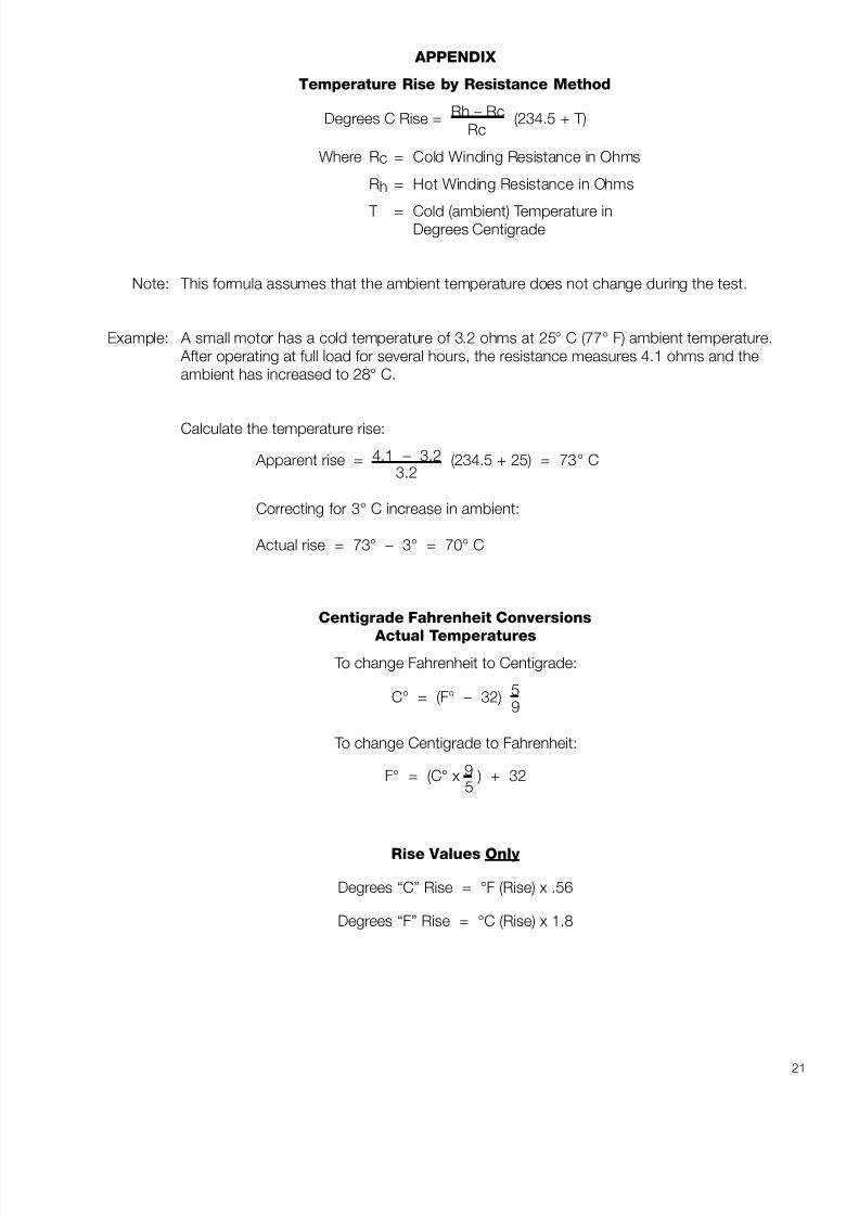
Temperature Rise by Resistance Method
Degrees C Rise = Rh – Rc (234.5 + T)Rc
Where Rc = Cold Winding Resistance in Ohms
Rh = Hot Winding Resistance in Ohms
T = Cold (ambient) Temperature inDegrees Centigrade
Note: This formula assumes that the ambient temperature does not change during the test.
Example: A small motor has a cold temperature of 3.2 ohms at 25° C (77° F) ambient temperature. After operating at full load for several hours, the resistance measures 4.1 ohms and theambient has increased to 28° C.
Calculate the temperature rise:
Apparent rise = 4.1 – 3.2 (234.5 + 25) = 73° C3.2
Correcting for 3° C increase in ambient:
Actual rise = 73° – 3° = 70° C
Centigrade Fahrenheit Conversions
Actual Temperatures
To change Fahrenheit to Centigrade:
C° = (F° – 32) 59
To change Centigrade to Fahrenheit:
F° = (C° x 9 ) + 325
Rise Values Only
Degrees “C” Rise = °F (Rise) x .56
Degrees “F” Rise = °C (Rise) x 1.8

8/20/2019 Elctric Motors BALDOR
http://slidepdf.com/reader/full/elctric-motors-baldor 28/124
22

8/20/2019 Elctric Motors BALDOR
http://slidepdf.com/reader/full/elctric-motors-baldor 29/124
METRIC MOTORS
The influx of foreign equipment during the ‘70’s and ‘80’s have put great numbers of metric motors inplants. As a result of this and the age of these motors, we are seeing inquiries for replacement motorsthat will match the IEC (International Electrical Commission) standards.
To help identify these motors and make suitable replacements, the following information could be useful.
RATING SYSTEM
One of the first things is that ratings are given in kilowatts (KW) rather than horsepower. The first thing todo is to convert from kilowatts to horsepower. It is important to note that even though KW is an electricalterm, in this case it is associated with mechanical output (just as horsepower is in this country). A simplefactor will make the conversion. Multiply the KW rating of the motor by 1.34 to get the horsepower of themotor. For example, a 2 KW motor would be equal to approximately 2.7 HP and the closest NEMA equivalent would be 3 HP.
The next item of concern would be the speed of the motor. Generally, somewhere on the nameplate of the foreign motor, you find the speed listed in RPM. The convention in Europe seems to be to show theno load speed of the motor and occasionally, the 50 cycle speed may be shown rather than the 60 cyclespeed. The following table shows a crossover from the 50 cycle speeds to the equivalent 60 cycle
speeds. In some cases, both the 50 and 60 cycle speeds are shown generally separated with a slash, forexample, 1500/1800 RPM. this would be a 4 pole motor that U. S. manufacturers would shownameplated with its full load speed. In this case it might be 1725 to 1760 RPM depending on the size of the motor.
FREQUENCY
50 HZ 60 HZ
SPEEDS (RPM) SPEEDS (RPM)
FULL LOAD FULL LOADPOLES SYNCHRONOUS SYNCHRONOUS
(Typical) (Typical)
2 3000 2850 3600 3450
4 1500 1425 1800 1725
6 1000 950 1200 1150
8 750 700 900 850
FAILURE REPLACEMENT
When an IEC (metric) motor fails in service the most practical way to proceed is to attempt to get an
exact metric framed replacement motor. Baldor and other manufacturers offer a limited selection of themost popular ratings for direct replacement.
When direct replacements are not available, the following information should be helpful in adapting NEMAframe motors to the metric application.
FRAME SIZE
European frame sizes are handled in a different way from U. S. frame sizes. They are based on the shaftheight (equivalent to our “D” dimension) in millimeters. For example, a 112 frame would have a 112millimeters shaft height. Convert this to inches by dividing 112 by 25.4 to get an equivalent domesticshaft height. In this case, the shaft height of a 112 frame would be slightly over 4.4 inches and theclosest NEMA frame motor would be a 180 series frame (182, 184, 182T or 184T) with a shaft height of
23
8/20/2019 Elctric Motors BALDOR
http://slidepdf.com/reader/full/elctric-motors-baldor 30/124
4.5 inches. This is true for IEC base mounted motors. In the case of this motor, it would be necessary tomake adjustments on the machine that would allow for either using the 180 series frame domestic motorand aligning the shaft height difference or by selecting a 145T or 56 frame motor (3.5" shaft height) andshimming up to get the proper alignment. The bolt pattern on the bases of IEC motors are given asmetric dimensions and it is impossible to get complete interchangeability with NEMA frame sizes.However, it is usually possible on foot mounted motors to adapt to domestic frame sizes by drilling newholes or making other accommodation to accept the different footprint of the NEMA frame motor. IECframe sizes for rigid base motors and the associated metric dimensions are shown on page 25.(Dimensions are in Millimeters — Divide by 25.4 to get inch equivalents.)
FLANGE MOUNTED MOTORS
Flange mounted motors become a real nemesis for conversion. There are two popular face mountingconfigurations used on the IEC motors. The most popular is the “B5” configuration which is closest toNEMA “D” flange motors. the important thing to note is that with the B5 flange, the clearance holes arein the flange and the threaded holes are in the mating part, such as the pump, gear reducer or machine.
The other popular IEC flange is the B14 flange. In this case, the threaded holes are in the face of themotor much the same as the NEMA “C” face motors.
IEC flange mounted motors all have metric rather than inch shaft diameters and where threaded holesare involved, they are metric rather than “inch” threads. To replace metric flange mounted motors, anexact flange mounting equivalent would be necessary unless someone is resourceful enough to make
adapter flanges that would convert NEMA “C” face motors to the metric dimensions required. Since thisusually is not the case, metric flange mounted motors have to be replaced with metric motors. Page 26shows typical metric dimensions for B5 and B14 metric motors. Note that dimensions are given inMillimeters.
Baldor is now offering selections of metric, three phase, flange mounted motors. We also stock somepermanent magnet DC motors that can be used as replacement units. On a custom basis whenreasonable quantities are involved we can build many different metric equivalent motors.
SUMMARY
This information should be useful in your day-to-day dealings in metric replacements.
24
8/20/2019 Elctric Motors BALDOR
http://slidepdf.com/reader/full/elctric-motors-baldor 31/124
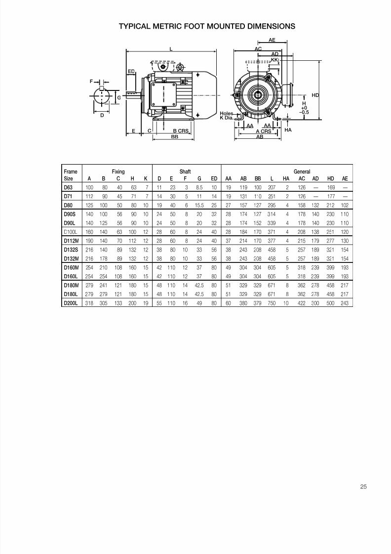
TYPICAL METRIC FOOT MOUNTED DIMENSIONS
F
G
D
KK
AC AD
HDH+0
–0.5
HA AA
A CRS AB
AA
HolesK Dia.
AE
L
ED
E C B CRS
BB
Frame Fixing Shaft General
Size A B C H K D E F G ED AA AB BB L HA AC AD HD AE
D63 100 80 40 63 7 11 23 3 8.5 10 19 119 100 207 2 126 — 169 —
D71 112 90 45 71 7 14 30 5 11 14 19 131 110 251 2 126 —
177 —
D80 125 100 50 80 10 19 40 6 15.5 25 27 157 127 295 4 158 132 212 102
D90S 140 100 56 90 10 24 50 8 20 32 28 174 127 314 4 178 140 230 110
D90L 140 125 56 90 10 24 50 8 20 32 28 174 152 339 4 178 140 230 110
D100L 160 140 63 100 12 28 60 8 24 40 28 184 170 371 4 208 138 251 120
D112M 190 140 70 112 12 28 60 8 24 40 37 214 170 377 4 215 179 277 130
D132S 216 140 89 132 12 38 80 10 33 56 38 243 208 458 5 257 189 321 154
D132M 216 178 89 132 12 38 80 10 33 56 38 243 208 458 5 257 189 321 154
D160M 254 210 108 160 15 42 110 12 37 80 49 304 304 605 5 318 239 399 193
D160L 254 254 108 160 15 42 110 12 37 80 49 304 304 605 5 318 239 399 193
D180M 279 241 121 180 15 48 110 14 42.5 80 51 329 329 671 8 362 278 458 217
D180L 279 279 121 180 15 48 110 14 42.5 80 51 329 329 671 8 362 278 458 217
D200L 318 305 133 200 19 55 110 16 49 80 60 380 379 750 10 422 300 500 243
25

8/20/2019 Elctric Motors BALDOR
http://slidepdf.com/reader/full/elctric-motors-baldor 32/124
TYPICAL METRIC FLANGE MOUNTED MOTOR DIMENSIONS
B5
MOTOR 2 POLES 4 POLES 6 POLESD E N M P S V X Y
SIZE HP KW HP KW HP KW
56 A 0.12 0.09 0.08 0.06 — —
9 20 80 100 120 2.5 7 167 10256 B 0.16 0.12 0.12 0.09 — —
63 A 0.25 0.18 0.16 0.12 — —
11 23 95 115 140 3 9 185 12263 B 0.33 0.25 0.25 0.18 — —
71 A 0.5 0.37 0.33 0.25 0.25 0.1814 30 110 130 160 3.5 9 211 140
71 B 0.75 0.55 0.5 0.37 0.33 0.25
80 A 1 0.75 0.75 0.55 0.5 0.3719 40 130 165 200 3.5 11 231 164
80 B 1.5 1.1 1 0.75 0.75 0.55
90 S 2 1.5 1.5 1.1 1 0.75 245
90 L 3 2.2 2 1.5 1.5 1.1 24 50 130 165 200 3.5 11 270 181
90 LL — — 2.5 1.8 — — 292
100 LA 4 3 3 2.2 2 1.5 304
100 LB — — 4 3 — — 28 60 180 215 250 4 14 304 207
112 M 5.5 4 5.5 4 3 2.2 343
132 S 7.5-10 5.5-7.5 7.5 5.5 4 3 364
132 M 12.5 9 10 7.5 5.5-7.5 4-5.5 38 80 230 265 300 4 14 402 259
132 L — — 12.5 9 — — 402
160 M 15-20 11-15 15 11 10 7.542 110 250 300 350 5 18 540 335
160 L 25 18.5 20 15 15 11
180 M 30 22 25 18.5 — —
48 110 250 300 350 5 18 600 374180 L 35 26 30 22 20 15
200 L 40-50 30-37 40 30 25-30 18.5-22 55 110 300 350 400 5 18 656 416
225 S — — 50 37 — —
* 60 140 350 400 450 5 18 680 416225 M 60 45 60 45 40 30
250 M 75 55 75 55 50 37 * 65 140 450 500 550 5 18 742 490
100 75 100 75 60 45280 S * 75 140 450 500 550 5 18 892 490125 90 125 90 75 55
* For 2 poles motors: Gr. 225 D = 55; E = 110 Gr. 250 D = 60; E = 140 Gr. 280 D = 65; E = 140
MOTOR 2 POLE 4 POLE 6 POLE D E N M P S V X Y SIZE HP KW HP KW HP KW
63 A 0.25 0.18 0.16 0.12 — —
11 23 60 75 90 2.5 M5 185 12263 B 0.33 0.25 0.25 0.18 — —
71 A 0.5 0.37 0.33 0.25 0.25 0.1814 30 70 85 105 2.5 M6 211 140
71 B 0.75 0.55 0.5 0.37 0.33 0.25
80 A 1 0.75 0.75 0.55 0.5 0.3719 40 80 100 120 3 M6 231 164
80 B 1.5 1.1 1 0.75 0.75 0.55
90 S 2 1.5 1.5 1.1 1 0.75 245
90 L 3 2.2 2 1.5 1.5 1.1 24 50 95 115 140 3 M8 270 181
90 LL — — 2.5 1.8 — — 292
100 LA 4 3 3 2.2 2 1.528 60 110 130 160 3.5 M8 304 207
100 LB — — 4 3 — —
112 M 5.5 4 5.5 4 3 2.2 28 60 110 130 160 3.5 M8 343 207
B14
26
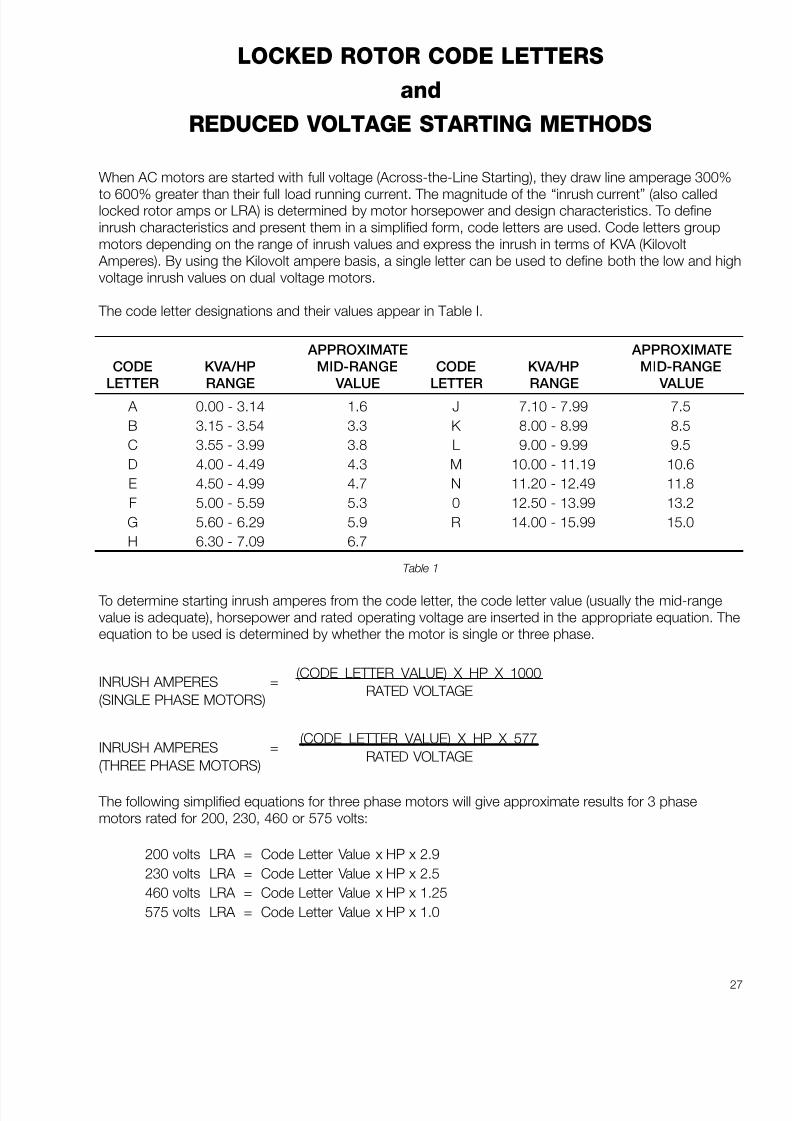
8/20/2019 Elctric Motors BALDOR
http://slidepdf.com/reader/full/elctric-motors-baldor 33/124
27
LOCKED ROTOR CODE LETTERS
and
REDUCED VOLTAGE STARTING METHODS
When AC motors are started with full voltage (Across-the-Line Starting), they draw line amperage 300%
to 600% greater than their full load running current. The magnitude of the “inrush current” (also calledlocked rotor amps or LRA) is determined by motor horsepower and design characteristics. To defineinrush characteristics and present them in a simplified form, code letters are used. Code letters groupmotors depending on the range of inrush values and express the inrush in terms of KVA (Kilovolt
Amperes). By using the Kilovolt ampere basis, a single letter can be used to define both the low and highvoltage inrush values on dual voltage motors.
The code letter designations and their values appear in Table I.
APPROXIMATE APPROXIMATE
CODE KVA/HP MID-RANGE CODE KVA/HP MID-RANGE
LETTER RANGE VALUE LETTER RANGE VALUE
A 0.00 - 3.14 1.6 J 7.10 - 7.99 7.5
B 3.15 - 3.54 3.3 K 8.00 - 8.99 8.5
C 3.55 - 3.99 3.8 L 9.00 - 9.99 9.5
D 4.00 - 4.49 4.3 M 10.00 - 11.19 10.6
E 4.50 - 4.99 4.7 N 11.20 - 12.49 11.8
F 5.00 - 5.59 5.3 0 12.50 - 13.99 13.2
G 5.60 - 6.29 5.9 R 14.00 - 15.99 15.0
H 6.30 - 7.09 6.7
Table 1
To determine starting inrush amperes from the code letter, the code letter value (usually the mid-rangevalue is adequate), horsepower and rated operating voltage are inserted in the appropriate equation. Theequation to be used is determined by whether the motor is single or three phase.
(CODE LETTER VALUE) X HP X 1000INRUSH AMPERES =
RATED VOLTAGE(SINGLE PHASE MOTORS)
(CODE LETTER VALUE) X HP X 577INRUSH AMPERES =
RATED VOLTAGE(THREE PHASE MOTORS)
The following simplified equations for three phase motors will give approximate results for 3 phasemotors rated for 200, 230, 460 or 575 volts:
200 volts LRA = Code Letter Value x HP x 2.9
230 volts LRA = Code Letter Value x HP x 2.5
460 volts LRA = Code Letter Value x HP x 1.25
575 volts LRA = Code Letter Value x HP x 1.0

8/20/2019 Elctric Motors BALDOR
http://slidepdf.com/reader/full/elctric-motors-baldor 34/124
28
STARTING METHODS
Across the line starting is used on a high percentage, probably over 95% of normal motor applications.Other starting methods (reduced voltage) are used mainly to control inrush current and limit it to valuesthat can be safely handled without excessive voltage dips and the accompanying light flicker.Occasionally, reduced voltage starters are used to reduce starting torque for smoother acceleration of loads. Various methods of reduced voltage starting have been developed. Table 2 shows the commonreduced voltage starter types and the results that can be expected in terms of motor voltage, line current,and the output torque of the motor. Caution should be used in applying reduced voltage starters on
certain types of loads. For example, a centrifugal pump, which is very easy to start, can be operated witheither wye-delta starting or part winding starting. These starting methods produce 33% and 50% of ratedmotor starting torque respectively and can easily start centrifugal pumps. They could also be expected tostart a compressor so long as it is unloaded. They could have difficulty starting a loaded inclinedconveyor or a positive displacement pump because of high starting torques required on these types of loads. The best starting method has to be one that achieves the desired result in inrush reduction andyields adequate starting torque to reliably start the load.
SQUIRREL CAGE INDUCTION MOTORS
% of Full Voltage Value*
Voltage Line Motor
Starting Method at Current OutputMotor Torque
Full Voltage 100 100 100
Autotransformer 80 % tap 80 64** 64
65 % tap 65 42** 42
50 % tap 50 25** 25
Primary reactor 80 % tap 80 80 64
65 % tap 65 65 42
50 % tap 50 50 25
Primary resistor Typical Rating 80 80 64Part Winding High Speed Motors (1/2 - 1/2) 100 70 50
Wye Start – Delta Run 100 33 33
* Percent of “ Across The Line Value”.
** Autotransformer magnetizing current not included. Magnetizing current usually less than 25 percent motor full-load current.
Table 2
In all cases, reduced voltage starters will cost substantially more than full voltage (across the line) starters.Standard motors can be used with autotransformer, primary reactor and primary resistor type starters. Inaddition, dual voltage motors can usually be utilized with part winding starters but only at the low voltage.Generally speaking, wye delta motors and part winding motors for higher voltage (for example, 460 or575 volts) must be made to order. This will raise the cost of the motor over a standardly available motorsuitable for use on other types of reduced voltage starting.

8/20/2019 Elctric Motors BALDOR
http://slidepdf.com/reader/full/elctric-motors-baldor 35/124
29
SOLID STATE STARTERS
So far we have discussed the traditional types of reduced voltage starters. The newer arrival is the solidstate soft-start control. With this type of device, the voltage is gradually raised electronically from a lowvalue at which the motor starts to turn the load up to the final across the line operating voltage. This typeof starter has the advantage of giving smoothly controlled acceleration and substantially reduced inrushcurrent.
SUMMARY
Overall, it is important to note that one of the primary objectives of reduced voltage starting is to limit theinrush current to a value that the power system or the local utility will accept. There are fringe benefitsderived from all types of reduced voltage starting. Reduced torque values that result from the lowerapplied voltage also reduce wear and tear on couplings, belts, gears and other equipment that is beingpowered by the motor. Solid state starters offer a smooth transition from standstill to full speed withreduced line current, controlled motor torque and acceleration.

8/20/2019 Elctric Motors BALDOR
http://slidepdf.com/reader/full/elctric-motors-baldor 36/124
30
8/20/2019 Elctric Motors BALDOR
http://slidepdf.com/reader/full/elctric-motors-baldor 37/124
N a t i o n a l C o n f e r e n c e o n P o w
e r T r a n s m
i s s i o n
31
UNDERSTANDING TORQUEEDWARD H. COWERN, P.E.
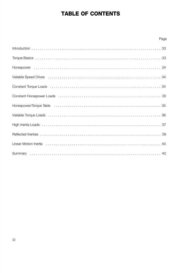
8/20/2019 Elctric Motors BALDOR
http://slidepdf.com/reader/full/elctric-motors-baldor 38/124
32
TABLE OF CONTENTS
Page
Introduction . . . . . . . . . . . . . . . . . . . . . . . . . . . . . . . . . . . . . . . . . . . . . . . . . . . . . . . . . . . . . . . . . 33
Torque Basics . . . . . . . . . . . . . . . . . . . . . . . . . . . . . . . . . . . . . . . . . . . . . . . . . . . . . . . . . . . . . . . 33
Horsepower . . . . . . . . . . . . . . . . . . . . . . . . . . . . . . . . . . . . . . . . . . . . . . . . . . . . . . . . . . . . . . . . 34
Variable Speed Drives . . . . . . . . . . . . . . . . . . . . . . . . . . . . . . . . . . . . . . . . . . . . . . . . . . . . . . . . . 34
Constant Torque Loads . . . . . . . . . . . . . . . . . . . . . . . . . . . . . . . . . . . . . . . . . . . . . . . . . . . . . . . . 34
Constant Horsepower Loads . . . . . . . . . . . . . . . . . . . . . . . . . . . . . . . . . . . . . . . . . . . . . . . . . . . . 35
Horsepower/Torque Table . . . . . . . . . . . . . . . . . . . . . . . . . . . . . . . . . . . . . . . . . . . . . . . . . . . . . . 35
Variable Torque Loads . . . . . . . . . . . . . . . . . . . . . . . . . . . . . . . . . . . . . . . . . . . . . . . . . . . . . . . . . 36
High Inertia Loads . . . . . . . . . . . . . . . . . . . . . . . . . . . . . . . . . . . . . . . . . . . . . . . . . . . . . . . . . . . . 37
Reflected Inertias . . . . . . . . . . . . . . . . . . . . . . . . . . . . . . . . . . . . . . . . . . . . . . . . . . . . . . . . . . . . . 39
Linear Motion Inertia . . . . . . . . . . . . . . . . . . . . . . . . . . . . . . . . . . . . . . . . . . . . . . . . . . . . . . . . . . 40
Summary . . . . . . . . . . . . . . . . . . . . . . . . . . . . . . . . . . . . . . . . . . . . . . . . . . . . . . . . . . . . . . . . . . 40

8/20/2019 Elctric Motors BALDOR
http://slidepdf.com/reader/full/elctric-motors-baldor 39/124
33
UNDERSTANDING TORQUEEdward H. Cowern, P.E.
New England District Manager, Baldor Electric Company65 South Turnpike Road • Wallingford, Connecticut 06492
In the process of applying industrial drive products,we occasionally are misled into believing that we areapplying horsepower. The real driving force is not
horsepower, it is TORQUE. This paper is developedto give a deeper understanding of torque, itsrelationship to horsepower, and the types of loadswe most frequently encounter.
INTRODUCTION
Torque is the twisting force supplied by a drive to theload. In most applications, a substantial amount of torque must be applied to the driven shaft before itwill even start to turn. In the English System, thestandard units of torque as used in the powertransmission industry are pound inches (lb. in.), or
pound feet (lb. ft.) and, in some cases, for very lowlevels of torque, you will encounter ounce inches(oz. in.).
TORQUE BASICS
At some time, we have all had difficulty in removingthe lid from a jar. The reason we have this trouble issimply that we are unable to supply adequate torqueto the lid to break it loose. The solution to ourdilemma may be to: 1) grit our teeth and try harder,2) use a rubber pad, or cloth, to increase the abilityto transmit torque without slippage, or 3) use a
mechanical device to help multiply our torqueproducing capability. Failing on all of the above, wemay pass the jar to someone stronger who canproduce more torque.
If we were to wrap a cord around the lid and supplya force to the end of the cord through a scale, asshown in Figure 1, we could get the exactmeasurement of the torque it takes to loosen the lid.
The torque required would be the force as indicatedon the scale., multiplied by the radius of the lid.
Figure 1
For example, if the indicated force on the scale atthe time of “breakaway” was 25 lbs. and the radius
of the lid was 1.5 inches, the torque required wouldhave been:
T = 25 lbs. x 1.5 in. = 37.5 lb. inches
Although this example does give a reasonableillustration of “torque”, it does not represent a verycommon example of requirements on industrialequipment.
There is, however, one additional important point thatcan be derived from the jar and the lid example;namely “Sticksion”. “Sticksion” is a term generatedto indicate the amount of torque required to break aload loose on its way to making the first revolution.
Generally speaking, the breakaway torquerequirement to start a machine will be substantiallygreater than that required to keep it running once ithas started. The amount of “sticksion” present in amachine will be dependent on the characteristics of the machine as well as the type of bearings that areused on the moving parts.
Table I indicates typical values of breakaway torquefor various general classifications of machinery.
BREAKAWAY & STARTING TORQUECHARACTERISTICS OF VARIOUS TYPES OF LOADS
% of Running
Torque Torque Types of Machines
Breakaway 120% to 130% General machines with Torque ball or roller bearings
Breakaway 130% to 160% General machines with Torque sleeve bearings
Breakaway 160% to 250% Conveyors and Torque machines with
excessive slidingfriction
Breakaway 250% to 600% Machines that have Torque “high” load spots in their
cycle, such as someprinting and punchpresses, and machineswith “cam” or “crank ”operated mechanisms.
Table 1
Assuming that the “sticksion”, or breakaway torque,has been overcome and the load has started, acontinuing amount of torque must be supplied tohandle the running torque requirements of themachine.
Torque = Force x Radius
Force
Radius
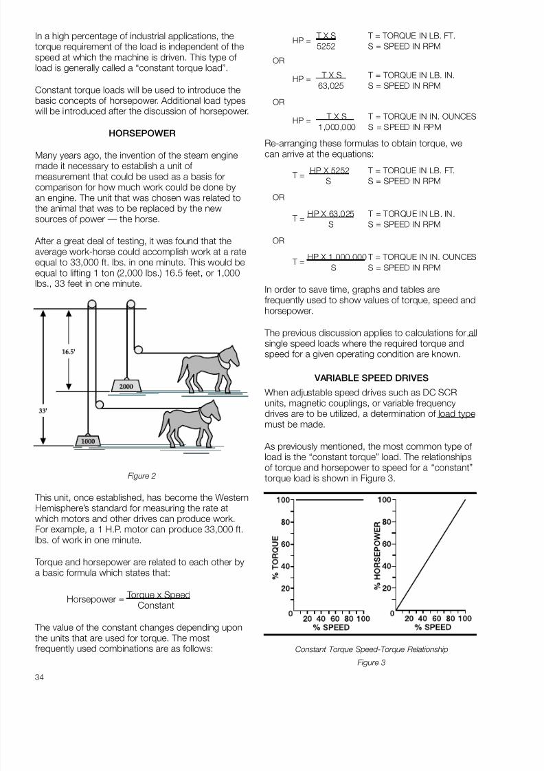
8/20/2019 Elctric Motors BALDOR
http://slidepdf.com/reader/full/elctric-motors-baldor 40/124
34
In a high percentage of industrial applications, thetorque requirement of the load is independent of thespeed at which the machine is driven. This type of load is generally called a “constant torque load”.
Constant torque loads will be used to introduce thebasic concepts of horsepower. Additional load typeswill be introduced after the discussion of horsepower.
HORSEPOWER
Many years ago, the invention of the steam enginemade it necessary to establish a unit of measurement that could be used as a basis forcomparison for how much work could be done byan engine. The unit that was chosen was related tothe animal that was to be replaced by the newsources of power — the horse.
After a great deal of testing, it was found that theaverage work-horse could accomplish work at a rateequal to 33,000 ft. lbs. in one minute. This would be
equal to lifting 1 ton (2,000 lbs.) 16.5 feet, or 1,000lbs., 33 feet in one minute.
Figure 2
This unit, once established, has become the WesternHemisphere’s standard for measuring the rate atwhich motors and other drives can produce work.For example, a 1 H.P. motor can produce 33,000 ft.
lbs. of work in one minute.
Torque and horsepower are related to each other bya basic formula which states that:
Horsepower = Torque x SpeedConstant
The value of the constant changes depending uponthe units that are used for torque. The mostfrequently used combinations are as follows:
HP = T X S T = TORQUE IN LB. FT.5252 S = SPEED IN RPM
OR
HP = T X S T = TORQUE IN LB. IN.63,025 S = SPEED IN RPM
OR
HP = T X S T = TORQUE IN IN. OUNCES
1,000,000 S = SPEED IN RPM
Re-arranging these formulas to obtain torque, wecan arrive at the equations:
T =HP X 5252 T = TORQUE IN LB. FT.
S S = SPEED IN RPM
OR
T =HP X 63.025 T = TORQUE IN LB. IN.
S S = SPEED IN RPM
OR
T =HP X 1,000,000 T = TORQUE IN IN. OUNCES
S S = SPEED IN RPM
In order to save time, graphs and tables arefrequently used to show values of torque, speed andhorsepower.
The previous discussion applies to calculations for allsingle speed loads where the required torque andspeed for a given operating condition are known.
VARIABLE SPEED DRIVES
When adjustable speed drives such as DC SCR
units, magnetic couplings, or variable frequencydrives are to be utilized, a determination of load typemust be made.
As previously mentioned, the most common type of load is the “constant torque” load. The relationshipsof torque and horsepower to speed for a “constant”torque load is shown in Figure 3.
Constant Torque Speed-Torque Relationship
Figure 3
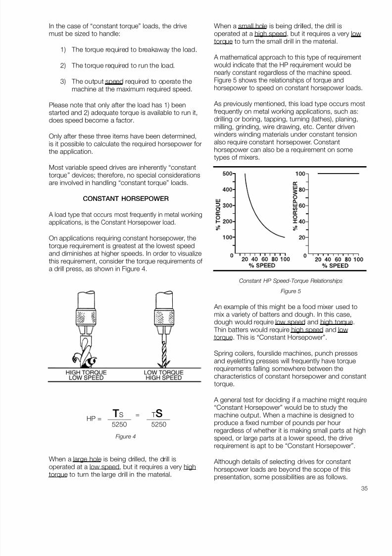
8/20/2019 Elctric Motors BALDOR
http://slidepdf.com/reader/full/elctric-motors-baldor 41/124
35
In the case of “constant torque” loads, the drivemust be sized to handle:
1) The torque required to breakaway the load.
2) The torque required to run the load.
3) The output speed required to operate themachine at the maximum required speed.
Please note that only after the load has 1) beenstarted and 2) adequate torque is available to run it,does speed become a factor.
Only after these three items have been determined,is it possible to calculate the required horsepower forthe application.
Most variable speed drives are inherently “constanttorque” devices; therefore, no special considerationsare involved in handling “constant torque” loads.
CONSTANT HORSEPOWER
A load type that occurs most frequently in metal workingapplications, is the Constant Horsepower load.
On applications requiring constant horsepower, thetorque requirement is greatest at the lowest speedand diminishes at higher speeds. In order to visualizethis requirement, consider the torque requirements of a drill press, as shown in Figure 4.
TS = T SHP = _______ _______
5250 5250
Figure 4
When a large hole is being drilled, the drill isoperated at a low speed, but it requires a very hightorque to turn the large drill in the material.
When a small hole is being drilled, the drill isoperated at a high speed, but it requires a very lowtorque to turn the small drill in the material.
A mathematical approach to this type of requirementwould indicate that the HP requirement would benearly constant regardless of the machine speed.Figure 5 shows the relationships of torque andhorsepower to speed on constant horsepower loads.
As previously mentioned, this load type occurs mostfrequently on metal working applications, such as:drilling or boring, tapping, turning (lathes), planing,milling, grinding, wire drawing, etc. Center drivenwinders winding materials under constant tensionalso require constant horsepower. Constanthorsepower can also be a requirement on sometypes of mixers.
Constant HP Speed-Torque Relationships
Figure 5
An example of this might be a food mixer used tomix a variety of batters and dough. In this case,dough would require low speed and high torque.
Thin batters would require high speed and lowtorque. This is “Constant Horsepower”.
Spring coilers, fourslide machines, punch pressesand eyeletting presses will frequently have torquerequirements falling somewhere between thecharacteristics of constant horsepower and constanttorque.
A general test for deciding if a machine might require“Constant Horsepower” would be to study themachine output. When a machine is designed toproduce a fixed number of pounds per hourregardless of whether it is making small parts at highspeed, or large parts at a lower speed, the driverequirement is apt to be “Constant Horsepower”.
Although details of selecting drives for constanthorsepower loads are beyond the scope of thispresentation, some possibilities are as follows.

8/20/2019 Elctric Motors BALDOR
http://slidepdf.com/reader/full/elctric-motors-baldor 42/124
36
“Constant Horsepower” loads can be handled byoversizing drives such as standard SCR units or slipcouplings. This is done by matching the drive’soutput torque with the machine’s requirement at thelow speed. Depending upon the speed range that isrequired, this can result in gross oversizing at thehigh speed. More practical approaches involve usingstepped pulleys, gearshift transmissions and metallicor rubber belt adjustable pitch pulley drives. Some
additional and more sophisticated approaches areDC (SCR) drives operating with a combination of armature control at full field power up to base speedand field weakening above base speed. Somevariable frequency drives can also be used atfrequencies above 60 HZ., with voltage heldconstant to achieve a moderate amount of constanthorsepower speed range.
VARIABLE TORQUE
The final load type that is often encountered is the“ Variable Torque” load. In general, variable torque loads
are found only in centrifugal pumps, fans and blowers.
A cross section of a centrifugal pump is shown inFigure 6. The torque requirement for this load typecan be thought of as being nearly opposite that of the “Constant Horsepower” load. For a variabletorque load, the torque required at low speed is verylow, but the torque required at high speed is veryhigh. Mathematically, the torque requirement is afunction of the speed squared and the horsepower isa function of the speed cubed.
Centrifugal Pump — Variable Torque Load
Figure 6
The relationships of torque and horsepower to speed
on “ Variable Torque” loads are shown in Figure 7.
Variable Torque — Speed-Torque Relationships
Figure 7
The key to drive sizing on “ Variable Torque” loads isstrictly related to providing adequate torque andhorsepower at the MAXIMUM speed that will berequired. MAXIMUM must be emphasized since a
9% increase in speed over the normal maximum willproduce a 30% increase in the horsepowerrequirement.
It is impossible to speculate on the number of motors that have been burned out because peoplehave unknowingly changed pulley ratios to obtain“more output” from their centrifugal pumps orblowers.
Table 2 illustrates the very dramatic changes inhorsepower requirements for relatively small changesin speeds that occur with “ Variable Torque” loads.
Table 2
Most variable speed drives are inherently capable of handling “ Variable Torque” loads provided that theyare adequately sized to handle the horsepowerrequirement at MAXIMUM speed.
% Speed % Torque % of Original % HPChange Change HP Change
–20 –36 51 –49
–15 –28 61 –39
–10 –19 73 –27
– 5 –10 86 –14
0 0 100 0
+5 +10 116 +16
+10 +21 133 +33
+15 +32 152 +52+20 +44 173 +73

8/20/2019 Elctric Motors BALDOR
http://slidepdf.com/reader/full/elctric-motors-baldor 43/124
37
HIGH INERTIA LOADS*
A discussion of load types would not be completewithout including information on “High Inertia Loads”.
Inertia is the tendency of an object that is at rest tostay at rest or an object that is moving to keepmoving.
In the industrial drive business, we tend to think immediately of flywheels as having high inertia; but,many other types of motor driven equipment, suchas: large fans, centrifuges, extractors, hammer mills,and some types of machine tools, have inertias thathave to be identified and analyzed in order toproduce satisfactory applications.
*A load is generally considered to be “High Inertia” when thereflected inertia at the motor shaft is greater than five timesthe motor rotor inertia.
THE HIGH INERTIA PROBLEM
The high inertia aspect of a load normally has to beconsidered only during acceleration anddeceleration. For example, if a standard motor isapplied to a large high inertia blower, there is apossibility that the motor could be damaged or failcompletely on its first attempt to start. This failurecould occur even though the motor might have morethan adequate torque and horsepower capacity todrive the load after it reaches the required runningspeed.
A good example of high inertia that most of us are
familiar with is a jet plane taking off. In this case, themaximum output of the engines is required toaccelerate the weight of the plane and contents.Only when it has reached take-off speed and isnearly ready to leave the ground do the engines startdoing the useful work of moving the plane to the finaldestination.
Similarly, when the plane lands, the reversed thrustof the engines and the brakes are used to slowdown and stop the inertia of the plane.
In the motor and drive industry, the inertia of arotating body is referred to as the WR2 or WK 2. Inthe English System. “W” is the weight in pounds and“R” or “K ” is the Radius of Gyration in feet. It isusually easy to obtain the weight of the body, butdetermining the radius of gyration can be a littlemore difficult. Figure 8 gives the formulas fordetermining the radius of gyration and WR2 of twofrequently occurring cylindrical shapes.
w: Steel = 490 Cast Iron = 450 Aluminum = 165
Figure 8
In most cases, the WR2 of flywheels can bedetermined by utilizing one, or both, of these normalshapes. In the case of flywheels having spokes, thecontribution made by the spokes can generally beignored and the inertia calculation based only on theformula for a Hollow Circular Cylinder as shown inFigure 8. The weight of the spokes should beincluded. If exact calculations are required, formulasare available to enable the calculation of WR2 valuesof nearly any shape.
In most cases, equipment manufacturers will be ableto provide the exact inertia values for a given
application.
Motor manufacturers can be asked to supply themaximum WK 2 limits for any specific applicationrequirement. (Please note WK 2 and WR2 are usedinterchangeably and they are the same).
The values shown in Table 3 are published in NEMA (National Electrical Manufacturers Association)standards MG-1. This table gives a listing of thenormal maximum values of WK 2 that could be safelyhandled by standard motors. This table can be usedas a guide. If the required WK 2 exceeds these
values, the motor manufacturer should be consulted.It is also important to note the details of paragraphs1, 2, and 3 that are associated with this table. If thenumber of starts required or the method of starting isnot “across the line”, the manufacturer should beconsulted.
RADIUS OF SIZE OF LOADPART GYRATION WR2 =
(IN FEET) POUNDS X FEET2
CIRCULAR CYLINDER.71R 1.58 W LR4
(R4 = RxRxRxR)
W = weight in pounds of one cubic foot of thematerial
HOLLOW
CIRCULAR CYLINDER
1.58w L (R24+R1
4 ).71 R22+R1
2
W = weight in pounds of one cubic foot of thematerial

8/20/2019 Elctric Motors BALDOR
http://slidepdf.com/reader/full/elctric-motors-baldor 44/124
38
WHY IS HIGH INERTIA A PROBLEM?
Prior to the time that a standard induction motorreaches operating speed, it will draw line currentseveral times the rated nameplate value. The high
current does not cause any problem if it is of shortduration; but, when the high currents persist for anextended period of time, the temperature within themotor can reach levels that can be damaging.
Speed, RPM
3600 1800 1200 900 720 600 514
HP Load WK 2 (Exclusive of Motor WK 2 ), Lb-Ft2
1 — 5.8 15 31 53 82 11811 / 2 1.8 8.6 23 45 77 120 1742 2.4 11 30 60 102 158 2283 3.5 17 44 87 149 231 3355 5.7 27 71 142 242 375 54471 / 2 8.3 39 104 208 356 551 798
10 11 51 137 273 467 723 104815 16 75 200 400 685 1061 153820 21 99 262 525 898 1393 201825 26 122 324 647 1108 1719 249130 31 144 384 769 1316 2042 295940 40 189 503 1007 1725 2677 388150 49 232 620 1241 2127 3302 478860 58 275 735 1473 2524 3819 568075 71 338 904 1814 3111 4831 7010
100 92 441 1181 2372 4070 6320 9180125 113 542 1452 2919 5010 7790 11310150 133 640 1719 3456 5940 9230 —200 172 831 2238 4508 7750 — —250 210 1017 2744 5540 — — —300 246 1197 3239 — — — —350 281 1373 3723 — — — —400 315 1546 — — — — —450 349 1714 — — — — —500 381 1880 — — — — —
MG 1-14.40 Load WK 2 for Integral horsepower
Polyphase Squirrel-cage InductionMotors
The table shown above lists the load WK 2 whichintegral-horsepower polyphase squirrel-cage inductionmotors, having performance characteristics inaccordance with Part 12*, can accelerate withoutinjurious heating under the following conditions:
1. Applied voltage and frequency in accordancewith 12.44.
2. During the accelerating period, a connectedload torque equal to or less than a torque
which varies as the square of the speed and isequal to 100 percent of rated-load torque atrated speed.
3. Two starts in succession (coasting to rest
between starts) with the motor initially at theambient temperature or one start with themotor initially at a temperature not exceedingits rated load operating temperature.
* Locked-rotor torque in accordance with 12.38.1,breakdown torque in accordance with 12.39.1, Class
A or B insulation system with temperature rise inaccordance with 12.43, and service factor inaccordance with 12.51.2.
Table 3

8/20/2019 Elctric Motors BALDOR
http://slidepdf.com/reader/full/elctric-motors-baldor 45/124
39
Figure 9(a) Figure 9(b)
Figure 9 (a) shows typical plots of available torquefrom a standard motor vs. speed. Also plotted oncurve (a) is the typical speed torque curve for a
Variable Torque load. The values of A 1, A 2, A 3, and
A 4 are the values of torque available to overcome theeffect of the inertia and accelerate the load atdifferent motor speeds as the motor speedincreases.
Referring to Figure 9 (b), you will see that during theaccelerating period this motor will draw line currentthat initially starts at 550% of rated current andgradually drops off as the motor approaches ratedspeed. A great deal of heat is generated within themotor during this high current interval. It is this heatbuild up that is potentially damaging to the motor if the acceleration interval is too long.
HOW LONG WILL IT TAKE?
Calculating the time to accelerate a direct coupledload can be determined quite easily by utilizing thefollowing formula:
t =WR2 x N
308T
T = AVERAGE ACCELERATING TORQUEIN LB. FT.
N = REQUIRED CHANGE IN SPEED
WR2 = INERTIA IN LB. FT.2
t = TIME IN SECONDS
The same formula can be rearranged to determinethe average accelerating torque required to producefull speed in a given period of time.
T =WR2 x N
308t
Referring back to Figure 9 (a), the acceleratingtorque would be the average value of the shadedarea. In most cases, for standard motors through100 HP, it is reasonable to assume that averageaccelerating torque available would be 150% of themotor full load running torque and that acceleratingtimes of 8-10 seconds, or less, would not bedamaging provided that starting is not repeatedfrequently. When load inertias exceed those shown in
Table 4, the application should be referred to themotor supplier for complete analysis.
REFLECTED INERTIAS
Up to this point, the only load inertias that have beenconsidered have been rotating inertias directlyconnected to the motor shaft.
On many applications, the load is connected to themotor by belts or a gear reducer. In these cases, the“Equivalent Inertia” or “Reflected Inertia” that is seenat the motor shaft is the important consideration.
In the case of belted or geared loads, the “Equivalent
Inertia” is given by the following formula:
EQUIVALENT WR2 = WR2LOAD
N 2
x 1.1*[ NM ]
WR2LOAD = INERTIA OF THE ROTATING
PART
N = SPEED OF THE ROTATINGPART
NM = SPEED OF THE DRIVINGMOTOR
*Please note: the x 1.1 factor has been added as asafety factor to make an allowance for the inertia andefficiency of the pulleys (sheaves) or gears used inthe speed change.
This formula will apply regardless of whether thespeed of the load is greater than, or less than, themotor speed.
Once the equivalent inertia has been calculated, theequations for accelerating time, or required torque,can be solved by substituting the equivalent WR2 inthe time or torque equation to be solved.
WHAT CAN BE DONE
When loads having high inertias are encountered,several approaches can be used. Some of thepossibilities are:
1. Oversize the motor.
2. Use reduced voltage starting.
3. Use special motor winding design.
4. Use special slip couplings between themotor and load.
5. Oversize the frame.
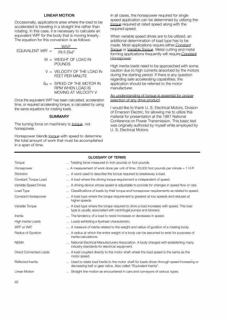
8/20/2019 Elctric Motors BALDOR
http://slidepdf.com/reader/full/elctric-motors-baldor 46/124
40
LINEAR MOTION
Occasionally, applications arise where the load to beaccelerated is traveling in a straight line rather thanrotating. In this case, it is necessary to calculate anequivalent WR2 for the body that is moving linearly.
The equation for this conversion is as follows:
W(V)2
EQUIVALENT WR2 = 39.5 (SM )2
W = WEIGHT OF LOAD INPOUNDS
V = VELOCITY OF THE LOAD INFEET PER MINUTE
SM = SPEED OF THE MOTOR INRPM WHEN LOAD ISMOVING AT VELOCITY V
Once the equivalent WR2 has been calculated, accelerationtime, or required accelerating torque, is calculated by using
the same equations for rotating loads.
SUMMARY
The turning force on machinery is torque, nothorsepower.
Horsepower blends torque with speed to determinethe total amount of work that must be accomplishedin a span of time.
In all cases, the horsepower required for singlespeed application can be determined by utilizing thetorque required at rated speed along with therequired speed.
When variable speed drives are to be utilized, anadditional determination of load type has to bemade. Most applications require either Constant
Torque or Variable Torque. Metal cutting and metalforming applications frequently will require ConstantHorsepower.
High inertia loads need to be approached with somecaution due to high currents absorbed by the motorsduring the starting period. If there is any questionregarding safe accelerating capabilities, theapplication should be referred to the motormanufacturer.
An understanding of torque is essential for properselection of any drive product.
I would like to thank U. S. Electrical Motors, Division
of Emerson Electric, for allowing me to utilize thismaterial for presentation at the 1981 NationalConference on Power Transmission. This basic textwas originally authored by myself while employed byU. S. Electrical Motors.
GLOSSARY OF TERMS
Torque … Twisting force measured in inch pounds or foot pounds.
Horsepower … A measurement of work done per unit of time. 33,000 foot pounds per minute = 1 H.P.Sticksion … A word used to describe the torque required to breakaway a load.
Constant Torque Load … A load where the driving torque requirement is independent of speed.
Variable Speed Drives … A driving device whose speed is adjustable to provide for changes in speed flow or rate.
Load Type … Classifications of loads by their torque and horsepower requirements as related to speed.
Constant Horsepower … A load type where the torque requirement is greatest at low speeds and reduces athigher speeds.
Variable Torque … A load type where the torque required to drive a load increases with speed. This loadtype is usually associated with centrifugal pumps and blowers.
Inertia … The tendency of a load to resist increases or decreases in speed.
High Inertia Loads … Loads exhibiting a flywheel characteristic.
WR2 or WK 2 … A measure of inertia related to the weight and radius of gyration of a rotating body.
Radius of Gyration … A radius at which the entire weight of a body can be assumed to exist for purposes ofinertia calculations.
NEMA … National Electrical Manufacturers Association. A body charged with establishing manyindustry standards for electrical equipment.
Direct Connected Loads … A load coupled directly to the motor shaft where the load speed is the same as themotor speed.
Reflected Inertia … Used to relate load inertia to the motor shaft for loads driven through speed increasing ordecreasing belt or gear ratios. Also called “Equivalent Inertia”.
Linear Motion … Straight line motion as encountered in cars and conveyors of various types.

8/20/2019 Elctric Motors BALDOR
http://slidepdf.com/reader/full/elctric-motors-baldor 47/124
41
FANS, BLOWERS, AND OTHER FUNNY LOADS
A family of motor applications that tend to confuse people who are not regularly involved with them, isthat of Variable Torque Loads. These loads represent a high percentage of motor requirements, so it isdesirable to have a little extra knowledge of the mysterious aspects of these loads. First, Variable TorqueLoads are fans, blowers, and centrifugal pumps. In general fans and blowers are moving air but
centrifugal pumps can be moving many kinds of liquids including water, petroleum products, coolants,etc.
There are two mysterious characteristics that these loads have. The first is the way they act when thespeed is changed. The rules that cover these characteristics are called the “affinity laws”. In order tosimplify we will discuss only the performance of these loads when they are applied to systems where theload is not changing. For example, we can discuss a pump arrangement as shown in Figure 1. This is apump circulating chilled or hot water through a closed system. What we find is that the torque requiredto drive the pump goes up as a squared function of speed (Speed2 ). Thus, increasing the speed causesthe torque required by the pump to go up, not directly with speed, but in proportion to the change of speed squared. For example, if we change the speed from 1,160 to 1760 RPM the torque required willgo up by the ratio of (1760 ÷ 1160)2. This would mean that the torque required would go up by 2.3 times
to 230% of the original value. Also, since horsepower (HP) is based on speed times torque, and thespeed has increased by 52%, the new value of HP would be 2.30 x 1.52 or almost 350% of the HPrequired at the original speed.
The dramatic increases in the horsepower required to drive these loads when speed increases is a littledifficult to understand but it is very important. It is also important because small decreases can result ingreat energy savings. For example, decreasing the speed of a variable torque load by only 20% will resultin a driving energy reduction of nearly 50%. This, obviously, has big importance when conservation isconsidered. It also accounts for the tremendous market that exists for variable frequency drives operating
Variable Air Volume (VAV) systems used in heating, ventilating, air conditioning and variable speedpumping used in similar systems.
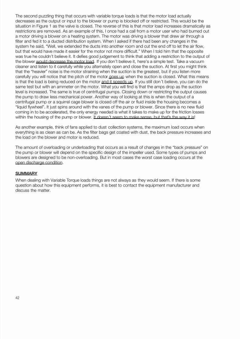
8/20/2019 Elctric Motors BALDOR
http://slidepdf.com/reader/full/elctric-motors-baldor 48/124
42
The second puzzling thing that occurs with variable torque loads is that the motor load actuallydecreases as the output or input to the blower or pump is blocked off or restricted. This would be thesituation in Figure 1 as the valve is closed. The reverse of this is that motor load increases dramatically asrestrictions are removed. As an example of this, I once had a call from a motor user who had burned outa motor driving a blower on a heating system. The motor was driving a blower that drew air through afilter and fed it to a ducted distribution system. When I asked if there had been any changes in thesystem he said, “Well, we extended the ducts into another room and cut the end off to let the air flow,but that would have made it easier for the motor not more difficult.” When I told him that the oppositewas true he couldn’t believe it. It defies good judgement to think that adding a restriction to the output of the blower would decrease the motor load. If you don’t believe it, here's a simple test. Take a vacuumcleaner and listen to it carefully while you alternately open and close the suction. At first you might think that the “heavier” noise is the motor straining when the suction is the greatest, but if you listen morecarefully you will notice that the pitch of the motor goes up when the suction is closed. What this meansis that the load is being reduced on the motor and it speeds up. If you still don ’t believe, you can do thesame test but with an ammeter on the motor. What you will find is that the amps drop as the suctionlevel is increased. The same is true of centrifugal pumps. Closing down or restricting the output causesthe pump to draw less mechanical power. Another way of looking at this is when the output of acentrifugal pump or a squirrel cage blower is closed off the air or fluid inside the housing becomes a“liquid flywheel”. It just spins around with the vanes of the pump or blower. Since there is no new fluidcoming in to be accelerated, the only energy needed is what it takes to make up for the friction losses
within the housing of the pump or blower. It doesn’t seem to make sense, but that’s the way it is!
As another example, think of fans applied to dust collection systems, the maximum load occurs wheneverything is as clean as can be. As the filter bags get coated with dust, the back pressure increases andthe load on the blower and motor is reduced.
The amount of overloading or underloading that occurs as a result of changes in the “back pressure” onthe pump or blower will depend on the specific design of the impeller used. Some types of pumps andblowers are designed to be non-overloading. But in most cases the worst case loading occurs at theopen discharge condition.
SUMMARY
When dealing with Variable Torque loads things are not always as they would seem. If there is somequestion about how this equipment performs, it is best to contact the equipment manufacturer anddiscuss the matter.

8/20/2019 Elctric Motors BALDOR
http://slidepdf.com/reader/full/elctric-motors-baldor 49/124
43
RMS HORSEPOWER LOADING
There are a great many applications especially in hydraulics and hydraulically-driven machines that havegreatly fluctuating load requirements. In some cases, the peak loads last for relatively short periodsduring the normal cycle of the machine. At first glance, it might seem that a motor would have to besized to handle the worst part of the load cycle. For example, if a cycle included a period of time where18 HP is required, then the natural approach would be to utilize a 20 HP motor. A more practicalapproach to these types of “duty cycle loads” takes advantage of an electric motor’s ability to handle
substantial overload conditions as long as the period of overload is relatively short compared to the totaltime involved in the cycle.
The method of calculating whether or not the motor will be suitable for a particular cycling application iscalled the RMS (root mean squared) horsepower loading method. The calculations required to properlysize a motor for this type of application are relatively simple and are presented in this paper.
The RMS calculations take into account the fact that heat buildup within the motor is very much greaterat a 50% overload than it is under normal operating conditions. Thus, the weighted average horsepoweris what is significant. RMS calculations determine the weighted average horsepower.
In addition to reducing the size and cost of a motor for a particular application, RMS loading also offers
the advantage of being able to improve the overall efficiency and power factor on a duty cycle type of load. For example, when an oversized motor is operated on a light load, the efficiency is generally fairlylow, so working the motor harder (with a higher average horsepower), will generally result in improvedoverall efficiency and reduced operating cost.
In order to use the RMS method of horsepower determination, the duty cycle has to be spelled out indetail as shown in the following example.
Step Horsepower Duration (seconds)
1 3 3
2 7.5 10
3 2.5 12
4 12.5 3
Repeats continuously.

8/20/2019 Elctric Motors BALDOR
http://slidepdf.com/reader/full/elctric-motors-baldor 50/124
44
In order to determine the RMS loading for the previous cycle, we can use the formula:
HP12 x t1 + HP2
2 x t2 + HP32 x t3 + HP4
2 x t4 + . . . . HPx2 x tx ______________
RMS HP =t1 + t2 + t3 + t4 + . . . . tx
The easiest way to approach this type of calculation is to make several columns as shown below and fillin the details underneath.
DurationStep Horsepower HP2 HP2 x Time
(Seconds)
1 3.0 9.0 3 27.0
2 7.5 56.3 10 563.0
3 2.5 6.3 12 75.6
4 12.5 156.3 3 468.8
28 1134.4
In this case, the total time of the cycle is 28 seconds and the summation of horsepower squared timestime for the individual steps in the cycle is 1134.4. when inserted into the equation, the RMS horsepowercomes out to be:
1134.4RMS HP = = 40.5 = 6.4
28
At first glance, it appears that a 7-1/2 HP motor would be adequate to handle the loading required bythis duty cycle. One further check has to be made and that is to determine if the motor has adequatepullout torque (breakdown torque) to handle the worst portion of the duty cycle without stalling. In thiscase, you would have to refer to the manufacturer’s data for the motor and determine the percent of
pullout torque that is available.
An additional safety factor should be used because the pullout torque of the motor varies with theapplied voltage. In fact, the pullout torque varies in relation to applied voltage squared. Thus, when themotor is running on 90% of rated voltage the amount of pullout torque available is only .9 x .9 orapproximately 80% of the value that it has at full rated voltage. For this reason, it is never safe to use thefull value of the pullout torque to determine if the overload can be handled. As a rule of good practice, itis wise not to use more than 80% of the rated pullout for a determination of adequacy.
In this case, referring to the Baldor CD ROM or Baldor website www.Baldor.com, we would find that a 7-1/2 HP, open drip proof motor with a catalog number M3311T, has a breakdown torque of 88.2 ft. lbs.and a full load operating torque of 22.3 ft. lbs. Thus, the actual pullout torque is 395% and utilizing 80%
of this value, we would find that the available, safe pullout torque would be 316%.
For the duty cycle shown, the required pullout torque percentage can be determined by the ratio of maximum horsepower to rated horsepower as follows:
% Pullout torque required = 12.5 (Max. HP Point) x 100 = 167%7.5 (Selected HP)
Since the available pullout torque at 90% of rated voltage is 316%, this 7-1/2 HP motor would be morethan adequate to handle this application.

8/20/2019 Elctric Motors BALDOR
http://slidepdf.com/reader/full/elctric-motors-baldor 51/124
45
The previous formula and example can be used for applications where the duty cycle repeats itself continuously, without interruption. When a duty cycle involves a period of shut-off time, a different formulais used. That formula is shown below.
HP12 x t1 + HP2
2 x t2 + HP32 x t3 + . . . . HPx
2 x tx ______________RMS HP =
t1 + t2 + t3 + . . . . tx + ts/C
where ts = number of seconds that motor is stoppedand C = 3 (open drip proof motors)
or C = 2 (totally enclosed motors)
This formula is the same as the previous one but it is modified to reflect the fact that during the non-operating (motor is at standstill) time, it also loses its capability of cooling itself.
The total amount of time for which RMS loading can be adequately calculated would depend somewhaton the size of the motor but, in general, it would be safe to utilize this method for duty cycles that totalless than 5 minutes from start to finish (of one complete cycle). If the total time is beyond 5 minutes, thenthe application should be referred to the motor manufacturer for more detailed analysis.
SUMMARY
RMS horsepower loading is a very practical way to reduce motor horsepower requirements on cyclingloads. With reduced motor horsepower also come a reduction in physical size and a reduction in initialcost, along with somewhat improved efficiency and reduced operating costs. If the selection procedure ishandled carefully, you can expect to get very good performance and reliability from the completed unit.
On servomotors and other adjustable speed applications, similar calculations are frequently made. Inthese cases armature amperes or required torques are substituted in place of horsepower. The resultingRMS amperes or RMS torque requirement is then compared to the motor’s continuous and peak ratingsto determine adequacy.
If you should have any questions regarding this method of sizing, please feel free to give us a call.

8/20/2019 Elctric Motors BALDOR
http://slidepdf.com/reader/full/elctric-motors-baldor 52/124
46

8/20/2019 Elctric Motors BALDOR
http://slidepdf.com/reader/full/elctric-motors-baldor 53/124
47
FACTORS THAT DETERMINE
INDUSTRIAL ELECTRIC BILLS
INTRODUCTION
A good deal of confusion exists regarding the factors that determine an industrial electric bill. Thefollowing information is presented to help sort out the various items on which billing is based, and to offer
suggestions on measures to help control and reduce electric utility bills.
Three basic factors and an optional item determine an industrial power bill. They are:
1 – Kilowatt hour consumption
2 – Fuel charge adjustments
3 – Kilowatt demand
4 – Power factor penalty (if any)
KILOWATT HOURS
The first of these is the easiest to understand since it is one that we are familiar with based on ourexperience at home. Kilowatt hour consumption is the measure of the electrical energy that has beenused during the billing period, without any regard to when or how it is used. In most cases, it isdetermined on a monthly basis by taking the accumulated kilowatt hour readings from the dial of aconventional kilowatt hour meter.
FUEL CHARGE ADJUSTMENT
Fuel charge adjustment, which is relatively new, is an adjustment factor determined monthly. It is basedon the cost of the fuel used to produce power during a given month. For example, in areas where waterpower is plentiful in the Spring, the contribution of water power might be great and its cost low. Thus, inthe Spring of the year, a downward adjustment might be made in fuel cost. In other instances, and at
other times of the year, a utility may find it necessary to burn large quantities of high priced imported oilto meet their requirements. When this occurs, there would be an upward adjustment of the fuel costcharge. Fuel charge adjustments are usually based on a unit charge per kilowatt hour.
KILOWATT DEMAND
Perhaps the least understood factor involved in calculating an industrial electric bill is the matter of demand. Demand is based on how much power is consumed during a given period of time. It ismeasured in kilowatts and it determines how much equipment the utility has to supply in terms of transformers, wire and generation capability, to meet a customer’s maximum requirements. Demand can,in some ways, be compared to the horsepower of an automobile engine. The normal requirement maybe relatively low but the size of the engine is determined by how much power is needed to accelerate the
car. Similarly, demand reflects a peak requirement. However, the term peak in relation to electric demandis frequently misunderstood. In virtually all cases, demand for an industrial plant is based on a 15 or 30minute average. Thus, brief high peaks, such as those that are present during the starting of largemotors, are averaged because the starting is of very short duration with respect to the demandaveraging interval.
A description of how the demand is measured may help to clarify this point. In each demand meter thereis a resetting timer. This timer establishes the demand interval and that interval, as mentioned previously,may be either 15 or 30 minutes. In effect, during the demand interval, the total number of revolutionsmade by the kilowatt hour meter disc is recorded. Thus, a high number of turns during the demandinterval would indicate a high demand, and a small total number of turns during the demand intervalwould indicate a low demand.

8/20/2019 Elctric Motors BALDOR
http://slidepdf.com/reader/full/elctric-motors-baldor 54/124
48
For example, when a large motor is started, it would cause the disc in the meter to surge forward for ashort period of time. However, as the initial surge passes, the meter would settle down to a normalrotation rate. Thus, the extra disc revolutions recorded as a result of the motor in-rush would not havemuch impact on the total number of revolutions that accumulate during a 15 or 30 minute interval. At theend of each demand averaging interval, the meter automatically resets and starts recording for the next15 minute period. This process goes on continuously. A special dial, which can be seen in Figure 1,records only the highest demand since the last time the meter was read. When the monthly reading istaken, the meter reader resets the demand to zero. Once again, the meter starts searching for thehighest 15 minute interval and it does so continuously until the next time it is read. It is the highestdemand for a month that is normally used to compute the bill. More about this later.
Figure 1
This is a typical demand meter used on a small commercial installation. The demand is determined byreading the position of the top needle and multiplying that reading by the meter constant. In this case,the reading is .725 multiplied by 12 for a demand reading of 8.7 KW. After the monthly reading is taken,the lock is unlocked, the needle reset to zero, and the meter is relocked. Accumulated kilowatt hours arerecorded in the conventional manner on the dials.
Figure 2 shows an example of typical manufacturing plants recorded demand over the course of twenty-four hours. This plant had a full first shift and partial second shift. By examining the graph, it is easy topick out some of the factors influencing the demand. The initial run up of demand occurs as the first shiftstarts. The growth of demand continues until the preparation for a coffee break begins. Coffee breaksresult in a major dip followed by another run up until the peak demand is reached shortly after 10 a.m.
Demand then stays reasonably steady until preparations for lunch and the lunch period begins.
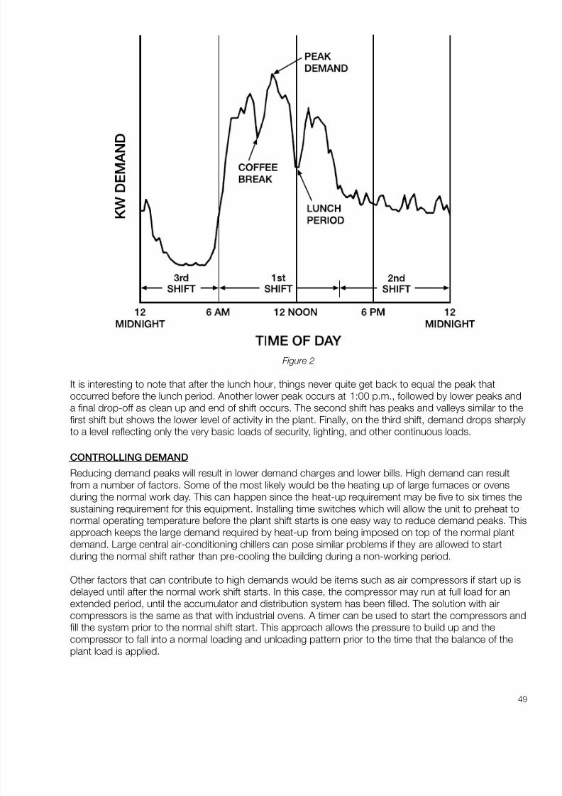
8/20/2019 Elctric Motors BALDOR
http://slidepdf.com/reader/full/elctric-motors-baldor 55/124
49
Figure 2
It is interesting to note that after the lunch hour, things never quite get back to equal the peak thatoccurred before the lunch period. Another lower peak occurs at 1:00 p.m., followed by lower peaks anda final drop-off as clean up and end of shift occurs. The second shift has peaks and valleys similar to the
first shift but shows the lower level of activity in the plant. Finally, on the third shift, demand drops sharplyto a level reflecting only the very basic loads of security, lighting, and other continuous loads.
CONTROLLING DEMAND
Reducing demand peaks will result in lower demand charges and lower bills. High demand can resultfrom a number of factors. Some of the most likely would be the heating up of large furnaces or ovensduring the normal work day. This can happen since the heat-up requirement may be five to six times thesustaining requirement for this equipment. Installing time switches which will allow the unit to preheat tonormal operating temperature before the plant shift starts is one easy way to reduce demand peaks. Thisapproach keeps the large demand required by heat-up from being imposed on top of the normal plantdemand. Large central air-conditioning chillers can pose similar problems if they are allowed to start
during the normal shift rather than pre-cooling the building during a non-working period.
Other factors that can contribute to high demands would be items such as air compressors if start up isdelayed until after the normal work shift starts. In this case, the compressor may run at full load for anextended period, until the accumulator and distribution system has been filled. The solution with aircompressors is the same as that with industrial ovens. A timer can be used to start the compressors andfill the system prior to the normal shift start. This approach allows the pressure to build up and thecompressor to fall into a normal loading and unloading pattern prior to the time that the balance of theplant load is applied.
8/20/2019 Elctric Motors BALDOR
http://slidepdf.com/reader/full/elctric-motors-baldor 56/124
50
With some thought, you will be able to discover some items within a facility that may fall into the categorythat can increase peak demand. The installation of seven day timers that will start essential compressors,ovens and other similar loads ahead of the first shift, can help reduce demand in most plants.
Demand charges are normally figured on a dollars per kilowatt basis. For example, one Connecticut utilityhas an industrial power rate that charges $401.00 for the first 100 kilowatts of demand and $2.20 foreach additional kilowatt.
DEMAND RATCHETS To encourage industrial plants to control their demand to reasonable levels, many utilities impose a twelvemonth ratchet on demand. What this means is that a very high demand, established in a particularmonth, will continue to be billed at a percentage of that high demand for eleven months unless actualdemand exceeds the established percentage of the previous peak. This type of arrangement can beexpensive to the power customers who are not careful in controlling their demand, and to industrieshaving high seasonal variations.
In many situations it is not possible to exercise any great degree of control over plant demand withoutencumbering operations unnecessarily and adding extra labor costs, etc. Even if a plant happens to be inone of these situations, it is important to understand the basic factors involved in demand and tounderstand what equipment within a facility is contributing to the total demand picture.
DEMAND MONITORING AND CONTROL
Demand monitoring and control equipment is available to help plant operators control their demand andenergy costs. This equipment is based on monitoring the demand build-up over the normal demandaveraging interval and taking action to curtail certain loads or operations to level peaks and prevent newpeaks from being established. For demand control to be effective, a plant must have electrical loads thatcan be deferred. Typical examples of deferrable loads would be water heating for storage, heat treating,and possibly the controlled shutdown of certain portions of ventilation systems where short terminterruptions would not create a problem.
Demand control is not for everyone but it can save substantial amounts of money when the right
conditions exist.
POWER FACTOR
Another misunderstood item in computing industrial electrical bills is power factor penalty. Power factor,in itself, is quite complicated to attempt to deal with in a broad manner. However, a capsule summarymight be in order.
Utilities have to size their transformers and distribution equipment based on the amount of amperes thatare going to be drawn by the customer. Some of these amperes are borrowed to magnetize inductiveloads within the plant. This borrowed power is later returned to the utility company without having beenbought. This borrowing and returning goes on at the rate of 60 times a second (the frequency of a 60
cycle power system). The borrowed power, as mentioned previously, is used to magnetize such things aselectric motors, transformers, fluorescent light ballasts, and many other kinds of magnetic loads within aplant. In addition to the borrowed power, there is the so-called real power. This is the power that is usedto produce heat from heating elements, light from incandescent bulbs, and to drive the shaft on motors.Power factor is a measure of the relative amounts of borrowed versus real power that is being usedwithin the plant.

8/20/2019 Elctric Motors BALDOR
http://slidepdf.com/reader/full/elctric-motors-baldor 57/124
51
Obviously, utilities would like to have the situation where the customer borrows nothing and utilizeseverything. In commercial and industrial situations, this ideal almost never exists. Plants with largequantities of lightly loaded motors or large quantities of electric welding equipment, may run at poorpower factors of 65 to 70%. On the other hand, plants with substantial amounts of electric heatingequipment as found in injection molding machines and fully loaded motors, could run with power factorsof 85 to 90%.
Plants with poor power factors can improve their situation by adding power factor correction capacitorsto their systems. Power companies like to have plants provide power factor correction capacitors sincethey lessen the number of amperes that need to be supplied. Within an individual plant, higher powerfactors also mean that incoming circuit breakers and distribution panels are not being taxed as much.So, within the plant, good power factor has some rewards as well.
POWER FACTOR PENALTIES
Some utilities impose power factor penalties. What this means is that when your power factor falls belowa pre-established level, a penalty charge may be added to the basic bill for kilowatt hours, fuel charge,and demand. The amount of the penalty is dependent on how far below the pre-established level thepower factor falls. There is no uniformity among utilities on how they determine the power factorpenalties and at what level they start. The variations in the way they are imposed is almost as large asthe number of different utilities in the country. The penalties can range from none at all, which is the case
with a great many power companies, to very substantial penalties imposed by others. Frequently, whenpenalties are imposed, there is also a reward arrangement. The reward is structured to reward highpower factor customers by giving them a credit on the monthly bill for having high power factor.
If you are concerned with power factor and any possible penalty you may be paying, the best approachis to contact the local power company. They will provide you with any information you might require onthe existing power factor and any penalties that are being paid. They can also help you compute theamount of power factor correction that you may need to eliminate any penalty charges.
SUMMARY
Understanding the four factors that go into determining industrial electric bills can help map approaches
to saving money on electric bills. Generally speaking, conservation efforts such as reduced lighting levels,buying more efficient motors, and replacing existing inefficient equipment with equipment having betterdesigns, will reduce both kilowatt hour consumption and kilowatt demand. Reducing kilowatt hourconsumption will also reduce fuel charge assessment. Shifting demand of certain types of equipment intomore optimum time periods when plant demand is low, can reduce kilowatt demand and the chargesassociated with it. Finally, improving power factor, if there are penalties being imposed, will help reducepower factor penalty charges.
A basic understanding of these four factors can help the conversation-minded to reduce overall electricenergy costs. Table I shows a simplified analysis of how various conservation and load control actionseffect the four components that make up the normal industrial electric bill. It can be used as a guide indirecting conservation and electric bill reduction.
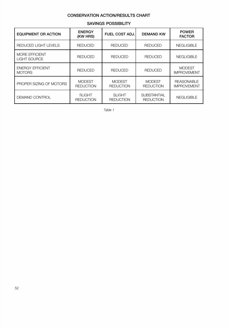
8/20/2019 Elctric Motors BALDOR
http://slidepdf.com/reader/full/elctric-motors-baldor 58/124
52
CONSERVATION ACTION/RESULTS CHART
SAVINGS POSSIBILITY
ENERGY POWEREQUIPMENT OR ACTION FUEL COST ADJ. DEMAND KW
(KW HRS) FACTOR
REDUCED LIGHT LEVELS REDUCED REDUCED REDUCED NEGLIGIBLE
MORE EFFICIENT REDUCED REDUCED REDUCED NEGLIGIBLELIGHT SOURCE
ENERGY EFFICIENT MODEST REDUCED REDUCED REDUCED
MOTORS IMPROVEMENT
MODEST MODEST MODEST REASONABLEPROPER SIZING OF MOTORS
REDUCTION REDUCTION REDUCTION IMPROVEMENT
SLIGHT SLIGHT SUBSTANTIALDEMAND CONTROL NEGLIGIBLE
REDUCTION REDUCTION REDUCTION
Table 1
8/20/2019 Elctric Motors BALDOR
http://slidepdf.com/reader/full/elctric-motors-baldor 59/124
53
ELECTRIC MOTORS AND POWER SYSTEMS
There seems to be a lot of confusion about the voltage standards for motors and why they are structuredthe way they are. There are, of course, two broad categories of motors, AC and DC. The voltagestandards for these two decidedly different motors are much different from each other. It will be the goalof this paper to try to reduce some of the confusion that exists in the AC motor voltage standards.
AC POWER SYSTEMS
To understand how voltage standards for motors are set it is important to know the basics of the powersystems they operate on. In general, utilities that supply power in the USA, and most other 60 cyclecountries, are required to provide power to the incoming point of a facility in multiples of 120 volts. Thusincoming equipment, such as circuit breaker panels, are rated in multiples of 120 volts. The commonvoltages are 120, 240, 480, and 600.
In addition, utilities are obligated by the regional governing authorities, (usually called Public UtilityCommissions) to regulate the voltage within a fairly narrow range such as plus or minus 5%.
For example, in most single phase residential systems the voltage is 120/240. It is brought to the buildingwith 3 wires, one being a neutral and the other two having voltages 120 volts different from the neutralwire. The voltage difference between the two “hot” wires is 240 volts.
In 3 phase systems the situation is a bit different. There are 3 phase, 3 wire, ungrounded systems
where the voltage between the three wires is 240 volts. The big brother of that system is the ungrounded3 phase, 3 wire 480 volt system. Ungrounded systems are usually found in older facilities.
In newer installations, the two most popular systems are called 4 wire grounded wye systems. The lowvoltage version is represented by a 120/208 volt system. The higher voltage version it is a 277/480 voltsystem. On both of these “grounded wye” systems, the low voltage portion (120 or 277 volts) is only
available as single phase. The high voltage (208 or 480 volts) is available as either single phase or 3phase. It should be noted that in the 4 wire grounded wye systems the high voltage is 1.73 times (thesquare root of 3) higher than the low voltage. These grounded wye systems are generally felt to be saferand more flexible than the older ungrounded systems. The flexibility comes from the ability to handlesingle phase lighting circuits, that operate at 120 volts or 277 volts, from the same system that feeds the3 phase circuits for motors, equipment for heating, air conditioning, elevators, and industrial machinery.
MOTORS
Now to discuss motors that operate on these 60 cycle power systems. In the case of “utilizationequipment”, such as motors, the voltage standards have been selected in multiples of 115 volts. Forexample, 115, 230, 460 and 575 volts. The standards for the “utilization equipment” have been
deliberately picked to be slightly less than the utility delivery voltages because in an industrial plant orlarge commercial building there may be several hundred feet between the incoming service point and theequipment. The distances involved will always lead to some voltage loss (or drop) through the wiring. Onshort runs this might be very small, even less than a volt, but on long heavily loaded runs it might be asmuch as 3 or 4% of the operating voltage. So choosing the utilization voltage to be different — and lessthan — the utility service voltage makes good sense.
There is also another factor that should be mentioned. The design standards for utilization equipment areset so the equipment is able to handle a voltage variation of plus or minus 10% of the nameplate rating.
Thus a motor nameplated at 460 volts should be able to be operated successfully up to 460 plus 10%(506 volts) and down to 460 minus 10% (414 volts). If everything is right with the voltage of the system
8/20/2019 Elctric Motors BALDOR
http://slidepdf.com/reader/full/elctric-motors-baldor 60/124
54
being in multiples of 120 plus or minus 5% and the equipment voltage being multiples of 115, plus orminus 10% then everything fits together like a neat jigsaw puzzle.
There is one oddity in the mix. That is 3 phase motors for the 120/208 volt power systems. For example,if the power system were to be 208 volts minus 5% (approximately 198 volts) and you were using a 230volt motor, then the 230 volt motor could only go down to 207 volts (-10%) without being in trouble.
There would be a discrepancy between the 198 volt low range of the system voltage, and the 207 lowestoperating voltage of a 230 volt motor, this could spell trouble. So how can this be addressed?
There are two ways that motor manufacturers have faced up to the problem. The first is to providemotors rated for 200 volts that can operate successfully down to 180 volts, or up to 220 volts. This is anadequate margin to cover the normal range of voltages that could be expected on a 120/208 voltsystem. But using this approach exclusively would mean that the complete inventory of motors in allsizes, enclosures, mechanical configurations, etc. would have to be duplicated to handle the motorrequirements for the 120/208 volt power systems. This would be very expensive and cumbersome,especially with the wide variety of small motors (under 10 HP) that exist.
So most motor manufacturers have taken a different approach to handling these smaller motors. Thisapproach is that by using a somewhat more conservative design on the 230 volt motors it is possible tocreate a 3 phase, tri-voltage motor with voltage ratings of 208-230/460. With this approach the 230 volt
winding ( and connection diagram) is used on the 208 volt power system. When this approach is takenthe motor manufacturer is essentially saying that this motor can be successfully operated on voltages aslow as 208 minus 10% or 187 volts. This approach usually works very well since 208 volt power systemsare normally used in small buildings with relatively short distances between the incoming power serviceand the utilization equipment. These short runs tend to make 208 volt power systems quite stable so thatthe limit of the motor’s low voltage capability is seldom tested.
On motors larger than 10 HP the 200 volt motor is generally the best choice, but in many situations 230volt motors are frequently and successfully applied on the 208 volt systems. In some cases a derate tableis provided for the “low voltage” situation. In other cases the motor service factor may be reduced from1.15 down to 1.0 when it is applied to a 208 volt power system.
Table 1 summarizes this information to show the power system voltage and description along with themotor voltage rating for single and 3-phase 60 Hertz motors.
50 HERTZ POWER SYSTEMS
There seems to be an endless array of possible combinations, but most of them do make sense. In 50hertz areas virtually all power systems are of the 4 wire, grounded wye type. A typical arrangement wouldbe a 220/380 volt power system. In this case, as in the case of a 120/208 volt 60 hertz system, the (lowvoltage) 220 volt power is only available as single phase and the 380 volt power is available as eithersingle or three phase.
As a result of the voltage being described as 220/380 we frequently see specifications indicating that
3-phase motors be wound for 220/380. Although feasible to do this, it is unnecessary because the3-phase motors will only be operated on 380 volt 3-phase power.
Some of the most popular voltages are 220/380 and 240/415. Recently European countries haverecognized the problem of trying to provide equipment for these two different voltage standards and havecome up with a standard that splits the difference. The new standard is 230/400. What this means is thatif the motor has an adequate amount of tolerance it can run on either a 380 volt system or a 415 voltsystem without being damaged. Also in most 50 Hertz systems, unlike the domestic systems, theequipment voltage rating tends to be the same as the supply voltage. In other words, 380 volt motors areused on 380 volt systems as opposed to situation in this country where the equipment utilization voltageis deliberately set lower than the supply voltage.

8/20/2019 Elctric Motors BALDOR
http://slidepdf.com/reader/full/elctric-motors-baldor 61/124
55
Table 2 shows some typical supply voltages and the appropriate equipment standards for 50 cyclepower systems.
When dealing with foreign voltage requirements it is always desirable to check the specified voltageagainst the listing of available voltages indicated in a U. S. Department of commerce booklet, Electric
Current Abroad* . If the specified voltage and frequency does not match the voltages shown in thebooklet for the country and city involved it should be a “Red Flag” that would suggest that the customerbe contacted and the voltage confirmed for accuracy. Mistakes can be very costly!!
*Copies of Electric Current Abroad are available from your local Baldor District Office.
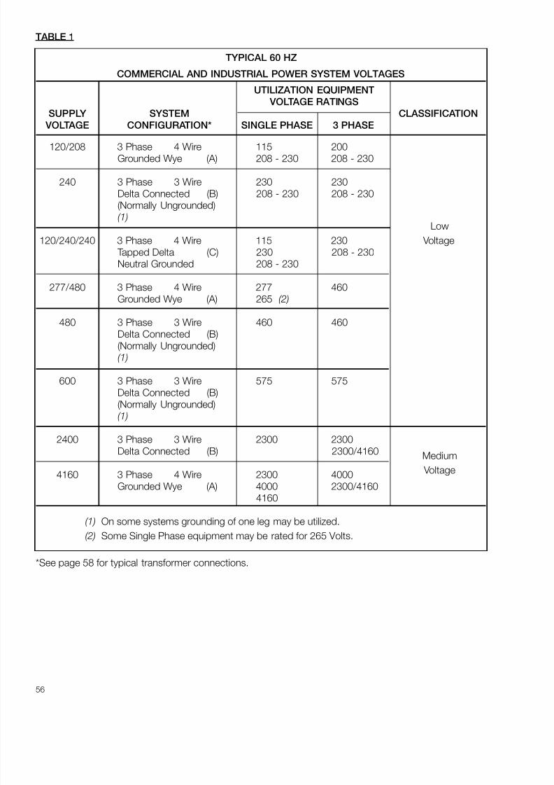
8/20/2019 Elctric Motors BALDOR
http://slidepdf.com/reader/full/elctric-motors-baldor 62/124
56
TABLE 1
TYPICAL 60 HZ
COMMERCIAL AND INDUSTRIAL POWER SYSTEM VOLTAGES
UTILIZATION EQUIPMENT
VOLTAGE RATINGS
SUPPLY SYSTEM CLASSIFICATION
VOLTAGE CONFIGURATION* SINGLE PHASE 3 PHASE
120/208 3 Phase 4 Wire 115 200Grounded Wye (A) 208 - 230 208 - 230
240 3 Phase 3 Wire 230 230Delta Connected (B) 208 - 230 208 - 230(Normally Ungrounded)(1)
Low
120/240/240 3 Phase 4 Wire 115 230 Voltage Tapped Delta (C) 230 208 - 230Neutral Grounded 208 - 230
277/480 3 Phase 4 Wire 277 460Grounded Wye (A) 265 (2)
480 3 Phase 3 Wire 460 460Delta Connected (B)(Normally Ungrounded)(1)
600 3 Phase 3 Wire 575 575Delta Connected (B)(Normally Ungrounded)(1)
2400 3 Phase 3 Wire 2300 2300Delta Connected (B) 2300/4160 Medium
4160 3 Phase 4 Wire 2300 4000 Voltage
Grounded Wye (A) 4000 2300/41604160
(1) On some systems grounding of one leg may be utilized.
(2) Some Single Phase equipment may be rated for 265 Volts.
*See page 58 for typical transformer connections.
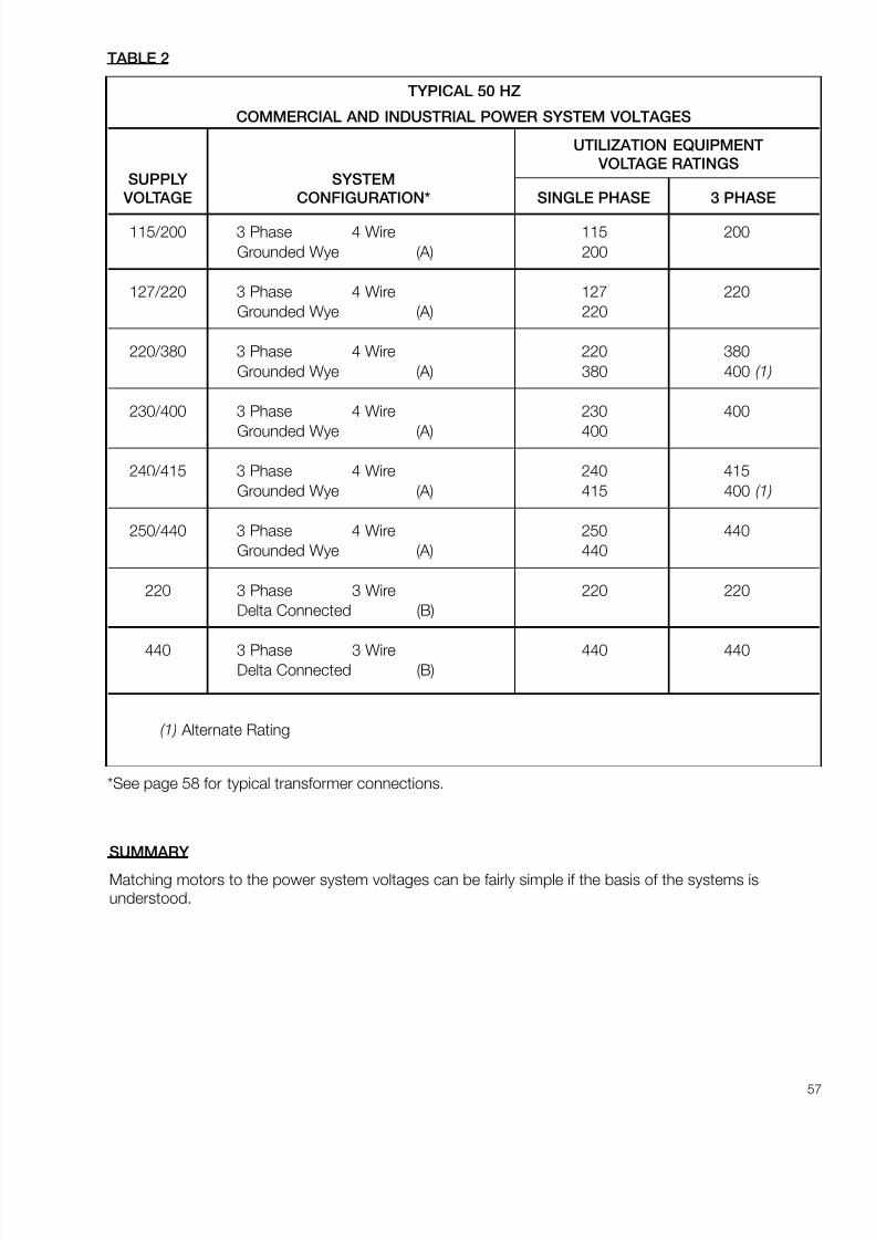
8/20/2019 Elctric Motors BALDOR
http://slidepdf.com/reader/full/elctric-motors-baldor 63/124
57
SUMMARY
Matching motors to the power system voltages can be fairly simple if the basis of the systems isunderstood.
TABLE 2
TYPICAL 50 HZ
COMMERCIAL AND INDUSTRIAL POWER SYSTEM VOLTAGES
UTILIZATION EQUIPMENT
VOLTAGE RATINGSSUPPLY SYSTEM
VOLTAGE CONFIGURATION* SINGLE PHASE 3 PHASE
115/200 3 Phase 4 Wire 115 200
Grounded Wye (A) 200
127/220 3 Phase 4 Wire 127 220Grounded Wye (A) 220
220/380 3 Phase 4 Wire 220 380
Grounded Wye (A) 380 400 (1)
230/400 3 Phase 4 Wire 230 400
Grounded Wye (A) 400
240/415 3 Phase 4 Wire 240 415
Grounded Wye (A) 415 400 (1)
250/440 3 Phase 4 Wire 250 440Grounded Wye (A) 440
220 3 Phase 3 Wire 220 220Delta Connected (B)
440 3 Phase 3 Wire 440 440Delta Connected (B)
(1) Alternate Rating
*See page 58 for typical transformer connections.
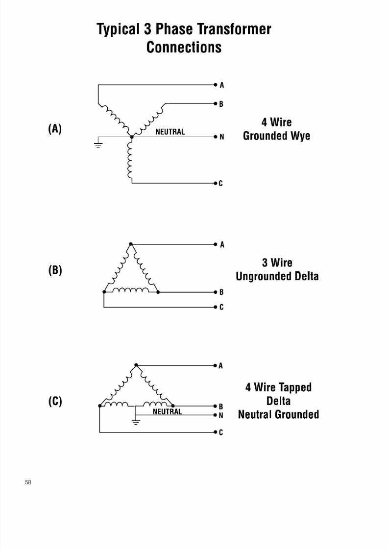
8/20/2019 Elctric Motors BALDOR
http://slidepdf.com/reader/full/elctric-motors-baldor 64/124
58
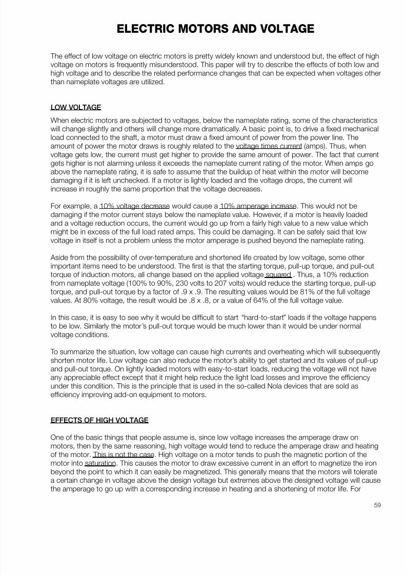
8/20/2019 Elctric Motors BALDOR
http://slidepdf.com/reader/full/elctric-motors-baldor 65/124
59
ELECTRIC MOTORS AND VOLTAGE
The effect of low voltage on electric motors is pretty widely known and understood but, the effect of highvoltage on motors is frequently misunderstood. This paper will try to describe the effects of both low andhigh voltage and to describe the related performance changes that can be expected when voltages otherthan nameplate voltages are utilized.
LOW VOLTAGE
When electric motors are subjected to voltages, below the nameplate rating, some of the characteristicswill change slightly and others will change more dramatically. A basic point is, to drive a fixed mechanicalload connected to the shaft, a motor must draw a fixed amount of power from the power line. Theamount of power the motor draws is roughly related to the voltage times current (amps). Thus, whenvoltage gets low, the current must get higher to provide the same amount of power. The fact that currentgets higher is not alarming unless it exceeds the nameplate current rating of the motor. When amps goabove the nameplate rating, it is safe to assume that the buildup of heat within the motor will becomedamaging if it is left unchecked. If a motor is lightly loaded and the voltage drops, the current willincrease in roughly the same proportion that the voltage decreases.
For example, a 10% voltage decrease would cause a 10% amperage increase. This would not bedamaging if the motor current stays below the nameplate value. However, if a motor is heavily loadedand a voltage reduction occurs, the current would go up from a fairly high value to a new value whichmight be in excess of the full load rated amps. This could be damaging. It can be safely said that lowvoltage in itself is not a problem unless the motor amperage is pushed beyond the nameplate rating.
Aside from the possibility of over-temperature and shortened life created by low voltage, some otherimportant items need to be understood. The first is that the starting torque, pull-up torque, and pull-outtorque of induction motors, all change based on the applied voltage squared . Thus, a 10% reductionfrom nameplate voltage (100% to 90%, 230 volts to 207 volts) would reduce the starting torque, pull-uptorque, and pull-out torque by a factor of .9 x .9. The resulting values would be 81% of the full voltage
values. At 80% voltage, the result would be .8 x .8, or a value of 64% of the full voltage value.
In this case, it is easy to see why it would be difficult to start “hard-to-start” loads if the voltage happensto be low. Similarly the motor’s pull-out torque would be much lower than it would be under normalvoltage conditions.
To summarize the situation, low voltage can cause high currents and overheating which will subsequentlyshorten motor life. Low voltage can also reduce the motor’s ability to get started and its values of pull-upand pull-out torque. On lightly loaded motors with easy-to-start loads, reducing the voltage will not haveany appreciable effect except that it might help reduce the light load losses and improve the efficiencyunder this condition. This is the principle that is used in the so-called Nola devices that are sold asefficiency improving add-on equipment to motors.
EFFECTS OF HIGH VOLTAGE
One of the basic things that people assume is, since low voltage increases the amperage draw onmotors, then by the same reasoning, high voltage would tend to reduce the amperage draw and heatingof the motor. This is not the case. High voltage on a motor tends to push the magnetic portion of themotor into saturation. This causes the motor to draw excessive current in an effort to magnetize the ironbeyond the point to which it can easily be magnetized. This generally means that the motors will toleratea certain change in voltage above the design voltage but extremes above the designed voltage will causethe amperage to go up with a corresponding increase in heating and a shortening of motor life. For

8/20/2019 Elctric Motors BALDOR
http://slidepdf.com/reader/full/elctric-motors-baldor 66/124
60
example, older motors were rated at 220/440 and had a tolerance band of plus/minus 10%. Thus, thevoltage range that they can tolerate on the high voltage connections would be 396 to 484. Even thoughthis is the so-called tolerance band, the best performance would occur at the rated voltage. The extremeends, either high or low, would be putting unnecessary stress on the motor.
Generally speaking, these tolerance bands are in existence not to set a standard that can be used all thetime but rather to set a range that can be used to accommodate the normal hour-to-hour swings in plantvoltage. Operation on a continuous basis at either the high extreme or the low extreme will shorten thelife of the motor.
Although this paper covers the effects of high and low voltage on motors, the operation of othermagnetic devices are effected in similar ways. Solenoids and coils used in relays and starters arepunished by high voltage more than they are by low voltage. This is also true of ballasts in fluorescent,mercury, and high pressure sodium light fixtures. Transformers of all types, including weldingtransformers, are punished in the same way. Incandescent lights are especially susceptible to highvoltage conditions. A 5% increase in voltage results in a 50% reduction in bulb life. A 10% increase involtage above the rating reduces incandescent bulb life by 70%.
Overall, it is definitely in the equipment’s best interest to have the utility company change the taps onincoming transformers to optimize the voltage on the plant floor to something that is very close to the
equipment ratings. In older plants, some compromises may have to be made because of the differencesin the standards on old motors (220/440) and the newer “ T ” frame standards (230/460), but a voltage inthe middle of these two voltages, something like 225 or 450 volts, will generally result in the best overallperformance. High voltage will always tend to reduce power factor and increase the losses in the systemwhich results in higher operating costs for the equipment and the system.

8/20/2019 Elctric Motors BALDOR
http://slidepdf.com/reader/full/elctric-motors-baldor 67/124
61
The graph shown in Figure 1 is widely used to illustrate the general effects of high and low voltage on theperformance of “ T ” frame motors. It is okay to use the graph to show “general” effects but, bear in mindthat it represents only a single motor and there is a great deal of variation from one motor design to thenext.
For example, the lowest point on the full load amp line does not always occur at 2-1/2% above ratedvoltage. On some motors it might occur at a point below rated voltage. Also the rise in full load amps atvoltages above rated, tends to be steeper for some motor winding designs than others.
Some general guidelines might be useful.
1. Small motors tend to be more sensitive to over-voltage and saturation than large motors.
2. Single phase motors tend to be more sensitive to over-voltage than three phase motors.
3. U-frame motors are less sensitive to over-voltage than “ T ” frames.
4. Premium efficiency Super-E motors are less sensitive to over-voltage than standard efficiencymotors.
5. Two pole and four pole motors tend to be less sensitive to high voltage than six pole and eightpole designs.
6. Over-voltage can drive up amperage and temperature even on lightly loaded motors. Thus, motorlife can be shortened by high voltage.
7. Full load efficiency drops with either high or low voltage.
8. Power factor improves with lower voltage and drops sharply with high voltage.
9. Inrush current goes up with higher voltage.
SUMMARY
There are very few desirable and many undesirable things that happen to electric motors and other
electrical equipment as a result of operating a power system at or near the ends of voltage limits. Thebest life and most efficient operation usually occurs when motors are operated at voltages close to thenameplate ratings.

8/20/2019 Elctric Motors BALDOR
http://slidepdf.com/reader/full/elctric-motors-baldor 68/124
62

8/20/2019 Elctric Motors BALDOR
http://slidepdf.com/reader/full/elctric-motors-baldor 69/124
63
UNBALANCED CURRENTS
Motor users and installers get concerned when they detect unbalanced phase currents on a 3-phasemotor. The question is frequently asked: “Is there something wrong with the motor?” The other questionis: “How much current unbalance can be tolerated?” This paper will attempt to answer those questions.
HISTORY
In the “Good Old Days” about the only sources of unbalanced phase currents was either a problem inthe motor, such as an unbalanced number of turns in the windings, an uneven air gap or unbalancedphase voltages. Winding or air gap problems are definitely motor related. On the other hand unbalancedphase voltages are a power system problem. Unbalanced voltages will generally produce unbalancedcurrents that are many times greater than the percentage of voltage unbalance. The ratio used is close to8:1. In other words, a voltage unbalance of 1% could create unbalanced phase currents of as much as8%.
A very unscientific way of looking at the problem is as follows: Suppose a motor has a nameplate fullload current of 10 amps. At full load the amps on each leg of the 3 phases added together would be 10+ 10 + 10 or 30. However, if the load is the same but the phase currents are unbalanced, the total of the3 legs added together will always be more than the total of the balanced currents. In this case the
currents might be 10.5, 11.3 and 12.1 for a total of 33.9. This is a very unscientific way of looking at it,but it is accurate in describing the effect. What this means is that high current on one leg doesn ’t meanthat the other two legs will be reduced by an equal amount. It can be said that unbalanced currentsalways result in higher operating temperature, shortened motor life and efficiency reduction.
The next question is “What creates unbalanced currents?” In years past, if the motor was not theproblem — the source of unbalanced currents was unbalanced phase voltages. When measuring line toline voltages from phase A to B, B to C, and C to A, detectable differences in the voltages would showup. The voltage differences would account for the unbalanced currents.
In today’s world there are other problems that are frequently not detectable with simple voltage tests.One problem of growing concern, is voltage distortion caused by harmonics in the power systemcurrents. This can happen if there are loads in the general area that draw non-linear (harmonic rich)currents from the power system, they can create voltage distortion in the normal voltage sine-wave that,in turn, can cause unbalanced currents in motors even when phase voltage differences are notdetectable with a voltmeter. For example, if you were to detect unbalanced motor currents and took measurements with a digital voltmeter on the three phases, they might be very close to one another. Thenatural tendency under these conditions, would be to blame the motor for the problem. When thishappens it is necessary to go a step further to identify or dismiss the motor as the source of theproblem. The test is to rotate all 3 phases. If the power phases are labeled A, B and C and the motorleads connected to them are labeled 1, 2, and 3, motor lead #1 might be reconnected to power supplylead B; motor lead #2 would be reconnected to power supply lead C, motor lead #3 would bereconnected to power supply lead A. Moving all three legs will keep the motor rotating in the same
direction. The currents are recorded on each power line leg before and after the connections arechanged. If the high current leg stays with the power line phase (for example, B), then the problem is apower supply problem rather than a motor problem. If, however, it moves with the motor leg, then it is amotor problem. This test will pinpoint the problem to be either power supply or motor.
HOW MUCH UNBALANCE CAN BE TOLERATED?
In general, this depends on the conditions that are found. If the motor is driving the load and the highestamperage of the three legs is below the nameplate Full Load rating, then generally it is safe to operate. If the high leg is above the nameplate rating, but within the normal service factor amps (for a motor with aservice factor, normally 1.15) then it is probably still safe to operate the motor. Also, it is not unusual tofind currents more unbalanced at no load than they will be under load, so the loaded amps should be

8/20/2019 Elctric Motors BALDOR
http://slidepdf.com/reader/full/elctric-motors-baldor 70/124

8/20/2019 Elctric Motors BALDOR
http://slidepdf.com/reader/full/elctric-motors-baldor 71/124
65
World Energy Engineering Congress
CONSERVING WITH
PREMIUM EFFICIENCY MOTORS

8/20/2019 Elctric Motors BALDOR
http://slidepdf.com/reader/full/elctric-motors-baldor 72/124
66
INTRODUCTION
Conservation through lighting alterations usingdifferent bulbs, ballasts and light sources is wellunderstood and easy to achieve. The use of improved efficiency three phase induction motorshas not been as accepted. There are a number of reasons why conservation efforts with motors havenot been as popular.
Light bulbs are sold by input ratings or watts. Withthe input rating being so prominent, it’s easy to
understand that if a 40 watt bulb is replaced by a 34watt bulb, there will be savings. But, unlike lightbulbs, electric motors are sold by output rating(horsepower) rather than input wattage. As a result,the measure used to evaluate differences in motorsis the efficiency rating and efficiency shows up inthe fine print and is not as easily understood as thewattage of bulbs.
The second reason lighting is different from motorsis that lights are usually on or off - - - not inbetween. But motors can be running at full load,
half load, quarter load, or no load. Frequently whenmotors are coupled through clutches to anintermittent motion system the motor may spend alot of the time operating with no load. Similarly, aircompressors may run unloaded much of the time.
As a result of varying load levels and intermittentloading, projected savings based on full loadefficiencies may not materialize.
That’s the bad news.
The good news is that premium efficiency motors,with their enhanced designs, result in loweroperating costs at any level of loading including noload. For example, the no load losses of a fivehorsepower premium efficiency motor might be 215watts. The no load losses of a standard motor of the same type might be 330 watts. Figure 1 showsa plot of watts loss for various load levels on aconventional motor versus the premium efficiency
motor of the same type. Curves of this type changedramatically with motor size, but trends are thesame.
Figure 1
THE BASICS
The process of converting electrical energy to
mechanical energy is never perfect. As much as wewould like to have a 100% efficient motor, it isimpossible to build a machine that will take 746watts of electricity (the equivalent of 1 HP) andconvert it to 1 HP of mechanical output. It alwaystakes somewhat more than 746 watts to yield 1HP’s worth of output. It does become easier toapproach 100% perfection with large motors thanwith small. For example, if the conversion processwere only 50% efficient, then it would take 1492watts of electricity to get 1 HP’s worth of output.Luckily, in industrial motors the conversion processis usually more efficient than this. The efficiency of standard industrial three phase motors usually runsfrom a level of approximately 75% at 1 HP up to94% at 200 HP. The curve shown in Figure 2illustrates the general trend of motor efficiencyversus motor size for standard and premiumefficiency motors.
CONSERVING WITH PREMIUM EFFICIENCY MOTORSEdward H. Cowern, P.E.
Wallingford, CT
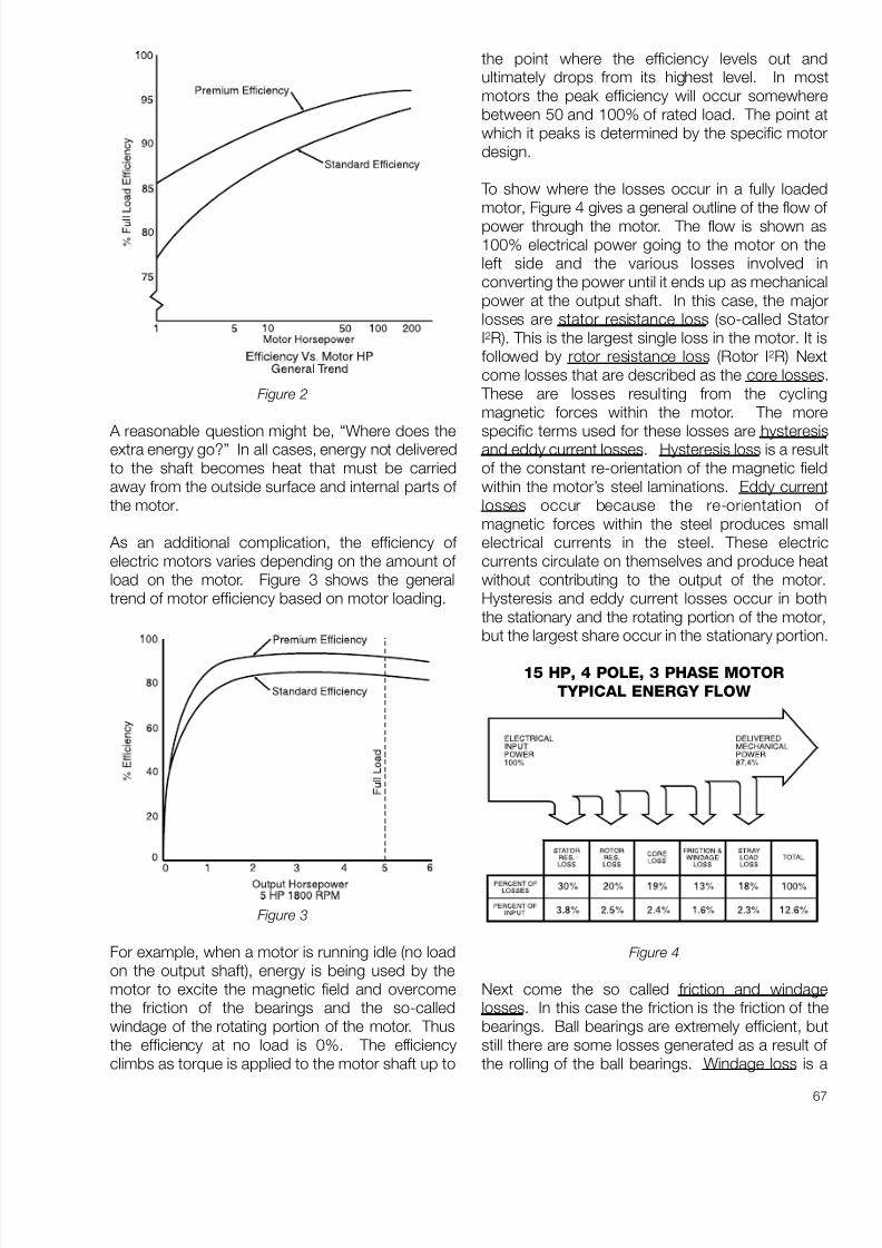
8/20/2019 Elctric Motors BALDOR
http://slidepdf.com/reader/full/elctric-motors-baldor 73/124
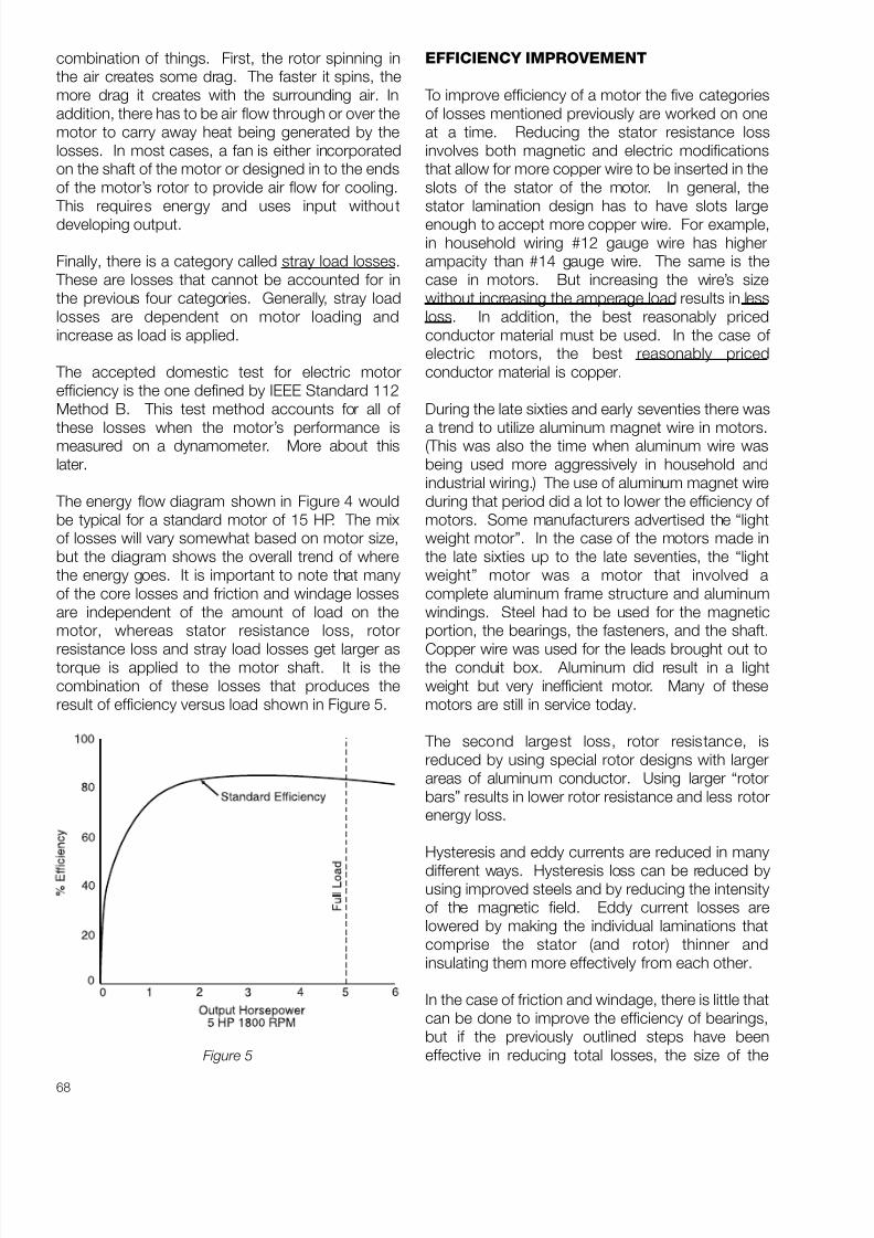
8/20/2019 Elctric Motors BALDOR
http://slidepdf.com/reader/full/elctric-motors-baldor 74/124
68
combination of things. First, the rotor spinning inthe air creates some drag. The faster it spins, themore drag it creates with the surrounding air. Inaddition, there has to be air flow through or over themotor to carry away heat being generated by thelosses. In most cases, a fan is either incorporatedon the shaft of the motor or designed in to the endsof the motor’s rotor to provide air flow for cooling.
This requires energy and uses input withoutdeveloping output.
Finally, there is a category called stray load losses. These are losses that cannot be accounted for inthe previous four categories. Generally, stray loadlosses are dependent on motor loading andincrease as load is applied.
The accepted domestic test for electric motorefficiency is the one defined by IEEE Standard 112Method B. This test method accounts for all of
these losses when the motor’s performance ismeasured on a dynamometer. More about thislater.
The energy flow diagram shown in Figure 4 wouldbe typical for a standard motor of 15 HP. The mixof losses will vary somewhat based on motor size,but the diagram shows the overall trend of wherethe energy goes. It is important to note that manyof the core losses and friction and windage lossesare independent of the amount of load on themotor, whereas stator resistance loss, rotor
resistance loss and stray load losses get larger astorque is applied to the motor shaft. It is thecombination of these losses that produces theresult of efficiency versus load shown in Figure 5.
Figure 5
EFFICIENCY IMPROVEMENT
To improve efficiency of a motor the five categoriesof losses mentioned previously are worked on oneat a time. Reducing the stator resistance lossinvolves both magnetic and electric modificationsthat allow for more copper wire to be inserted in theslots of the stator of the motor. In general, thestator lamination design has to have slots largeenough to accept more copper wire. For example,in household wiring #12 gauge wire has higherampacity than #14 gauge wire. The same is thecase in motors. But increasing the wire’s sizewithout increasing the amperage load results in lessloss. In addition, the best reasonably pricedconductor material must be used. In the case of electric motors, the best reasonably pricedconductor material is copper.
During the late sixties and early seventies there was
a trend to utilize aluminum magnet wire in motors.(This was also the time when aluminum wire wasbeing used more aggressively in household andindustrial wiring.) The use of aluminum magnet wireduring that period did a lot to lower the efficiency of motors. Some manufacturers advertised the “lightweight motor”. In the case of the motors made inthe late sixties up to the late seventies, the “lightweight” motor was a motor that involved acomplete aluminum frame structure and aluminumwindings. Steel had to be used for the magneticportion, the bearings, the fasteners, and the shaft.
Copper wire was used for the leads brought out tothe conduit box. Aluminum did result in a lightweight but very inefficient motor. Many of thesemotors are still in service today.
The second largest loss, rotor resistance, isreduced by using special rotor designs with largerareas of aluminum conductor. Using larger “rotorbars” results in lower rotor resistance and less rotorenergy loss.
Hysteresis and eddy currents are reduced in many
different ways. Hysteresis loss can be reduced byusing improved steels and by reducing the intensityof the magnetic field. Eddy current losses arelowered by making the individual laminations thatcomprise the stator (and rotor) thinner andinsulating them more effectively from each other.
In the case of friction and windage, there is little thatcan be done to improve the efficiency of bearings,but if the previously outlined steps have beeneffective in reducing total losses, the size of the

8/20/2019 Elctric Motors BALDOR
http://slidepdf.com/reader/full/elctric-motors-baldor 75/124
69
cooling fan can be reduced which helps increasemotor efficiency.
The last component of losses is stray load loss. Inthis case, various manufacturing techniques areused to reduce stray load losses. With each of thefive elements being worked individually andcollectively, substantial improvements in motorefficiencies can be achieved.
BASIS OF COMPARISON
There are many different terms used to compareefficiencies of one motor to another. The two mostoften heard are nominal efficiency and guaranteedminimum efficiency. It is easy to get confused as towhat basis should be used for determining potentialsavings from efficiency upgrades. The basis fornominal efficiency ratings can be explained in thefollowing manner. If a large batch of identical
motors were to be made and tested, the nominalefficiency would be the average efficiency of thebatch. Due to manufacturing tolerances, someunits might be less efficient and others moreefficient. However, the nominal is the predictableaverage of the lot.
The second term used is guaranteed minimumefficiency. The guaranteed minimum recognizesthe variations from one motor to the next and setsan arbitrary low limit. It says in essence, none of themotors in the batch will be less efficient than this.
With these two choices, what should be the basisof comparison?
If you had to stake your life on the result and itinvolved a single motor, then guaranteed minimumefficiency would be the one to use. However, if you’re considering a number of motors in a rangeof sizes, and you’re not held precisely to what thefinal minimum result would be, then nominalefficiency is the proper basis of comparison.Nominal efficiency also makes it easier because
nominal efficiency is stamped on the nameplate of the motor. In addition, nominal and minimumguaranteed are related to each other by a formulaestablished by the National Electrical Manufacturers
Association. So comparing different motors on thebasis of “nominal” is really equivalent to comparingon the basis of minimum guaranteed.
Of more importance is the standard by which theefficiency is going to be determined. The standardshould always be IEEE 112 Method B. Of all
standards developed for determining efficiency ofmotors, this is one of the most rigorous.
Other standards that are used, particularly someinternational standards, do not demand suchrigorous testing. In some cases, efficiency is merelycalculated rather than measured. In virtually alcases the “other” standards will give efficiencieshigher than the tougher IEEE 112 standard. Thecorrect basis of comparison should be that almotors be compared on the same standard. TheIEEE method also measures the efficiency in the hotrunning condition. This makes it more accuratebecause the efficiency of the motor will fall slightlyas operating temperature rises.
A FEW PRECAUTIONS
The result of using premium efficiency motors is notnecessarily without some pitfalls. For example,
premium efficiency motors run somewhat faster(have less slip) than their less efficient counterparts A premium efficiency motor might run at a full loadspeed of 1760 RPM. The motor it replaces mightbe running at 1740 RPM. This can help or hurtconservation efforts depending on the type of loadthe motor is driving. For example, if it is driving aconveyor handling bulk materials, the higher speedwill result in getting the job done faster. Also, if theconveyor has periods of light load, the reducedlosses of the motor will save energy during thatperiod of time.
The same situation exists on many pumpingapplications where a specific amount of fluid isgoing to be used to fill a tank. If the motor runsfaster, the work is completed sooner and the motoris shut down earlier. In these cases theconsequence of the increased speed does notresult in increased energy use. But there areapplications such as chilled water circulatingpumps where the extra speed can reduceexpected savings.
The reason this can happen is that centrifugapumps along with other types of variable torqueloads such as blowers and fans, requirehorsepower proportional to speed cubed. As aresult a slight increase in speed can result in asharper increase in horsepower and energy used.
A typical example might be where the original motoris directly connected to a centrifugal pump. Theoriginal motor’s full load speed is 1740 RPM. Thereplacement premium efficiency motor, driving thesame pump, has a higher speed of 1757 RPM. The

8/20/2019 Elctric Motors BALDOR
http://slidepdf.com/reader/full/elctric-motors-baldor 76/124
70
resulting difference of 1% will increase thehorsepower required by the pump by 1.01 x 1.01 x1.01 = 1.03. Thus the horsepower required by theload is increased by 3% above what it would be if the pump speed had remained the same. Evenwith increased speed there remains, in most cases,some improvement in efficiency and reduction inenergy usage although it may not be what youhoped to achieve.
On fans and blowers the same thing would holdtrue if no changes take place to bring theequipment speed back to the original value. Forexample, if a motor drives a fan with a belt drive andthe fan speed is 650 RPM, changing the motor andusing the same exact pulley and belt wouldincrease the fan’s speed and the horsepowerrequired. This could reflect back as extra energydrawn from the power system. However, if anadjustment is made in the ratio between the pulleys
to restore the fan speed to the original value, thenthe anticipated savings will materialize. These typesof challenges make it desirable to look at efficiencyupgrading as a “system” rather than strictly a motorconsideration.
DRIVEN EQUIPMENT EFFICIENCY
As consumers, we are faced with energy efficientratings on new refrigerators, air conditioners, hotwater heaters, etc. The same type of data is usuallynot nearly as available on machinery purchased for
industrial and commercial installations. Forexample, not all pumps with the same performancespecifications have the same efficiency. Similarlynot all air compressors have the same efficiencies.Some air compressors have dramatically betterefficiencies than others especially when operated atless than full load. At first glance it looks like aproblem of evaluating one versus the other could beinsurmountable. However, a good vendor shouldbe willing to share certified performanceinformation.
PROPER SIZING
In addition to the challenge of different efficienciesfrom different equipment manufacturers there isalso the matter of selecting properly sizedequipment. For example, a pump oversized for the
job may be much less efficient than a pumpproperly sized. Similarly, an air compressoroversized for the job may be much less efficientthan one selected to more closely match actualrequirements.
EVALUATION
There are a great many ways to approach capitalinvestment and determine rates of return, payback periods, present worth, etc. Most of these are goodfor large capital investments where there may berisk involved if the project doesn't work out or if theproduct changes or is affected by marketdynamics. Electric motors and other conservationmeasures tend to be a simpler problem and usuallydo not need the rigorous mathematical treatmentfound in these more complicated analysisapproaches. Formulas to determine savings arefound in the appendix of this paper.
IDEAL MOTOR LOADING
In the process of upgrading efficiency a questioncomes up as to what the ideal load conditionsshould be for replacement motors. A motor that is
overloaded will have short life. In the oppositesituation, a motor that is grossly oversized for the job it is asked to do, is inefficient. Figure 6 shows atypical load versus efficiency curve for a 10 HPmotor. This curve shows that in the upper half of theload range (50% - 100%) the efficiency stays fairlyconstant at a high level. At loads below 50% theefficiency drops dramatically. In most situations,once the motor is in operation and running, the loaddoesn’t vary. This is especially true on heating,ventilating and air conditioning applications such ascirculator pumps and air handling equipment. On
other types of machinery such as air compressorsand machine tools, the load may cycle on and off,heavily loaded for some periods and lightly loadedat other times. Obviously on cycling loads it isimportant to size the motor so that it can handle theworst case condition. However, on continuouslyloaded motors it is desirable to load motors atsomewhere between 50 and 100% and moreideally in the range of 75 to 80%. By selecting amotor to be loaded in this range, high efficiency isavailable and motor life will be long. Also, byloading at somewhat less than 100% the motors
can more easily tolerate such things as low voltageand high ambient temperatures that can occursimultaneously in summer. This approach will getsomewhere closer to optimum efficiency whilepreserving motor life.

8/20/2019 Elctric Motors BALDOR
http://slidepdf.com/reader/full/elctric-motors-baldor 77/124
71
Figure 6
EXISTING MOTOR EFFICIENCY UPGRADES
In a commercial or large industrial situation thequestion comes up: “Should motors be replaced ona wholesale basis throughout the plant orselectively changed?” There is probably no hardrule for this, but here are some ideas. Thewholesale change-out of all motors in a plant orcommercial building generally cannot be justified ona cost basis. The reason for this is that some of the motors may be used only intermittently. Suchthings as test equipment, trash compactors andother similar situations support the case for not
changing everything. There can also be othercomplications such as specialized motors found onsome types of pumps and machine tools and oldmotors (where direct interchanges are not readilyavailable). These fall into a cloudy area wherechange-out may not be justified.
Motors having the greatest potential for savings arethose that run on an extended basis with near fullload conditions. These are the logical candidatesfor any change-out program.
UTILITY REBATE PROGRAMS
A major breakthrough occurred a short time agowhen court rulings were passed down so utilitiescould offer their customers financial help forconservation efforts. Prior to this change utilitycompanies were in a dilemma. If they financed andpromoted conservation, the cost of the effort,personnel, equipment, etc., was an expensethat reduced their sales and income. This set up adouble disincentive for utility support of con-servation measures.
Under the new rules, utility money expended onconservation can be considered as a capitainvestment. Put differently, this means thatfinancing the “buy back ” of one kilowatt of capacitythrough conservation efforts is equivalent, foraccounting purposes, to investing money to build agenerating plant capable of generating that extrakilowatt. This new accounting approach hasunleashed great amounts of money that utilities arenow willing (in some cases mandated) to invest intheir customers’ conservation efforts. A statementmade by one utility indicated it was now possible to“buy back ” a kilowatt of capacity for roughly two-thirds of the cost of installing a new kilowatt ofcapacity. This new approach has turned a losingsituation into a win-win situation for utilities and theircustomers.
The result of this has been a great flurry of activityin utility rebate programs to finance various types of
conservation efforts. Again, as with individuainitiatives on conservation, lighting has receivedmajor attention because it is easy to understandand large gains can be quickly achieved. Electricmotors and drive systems are now receiving moreattention because they represent the equipmentthat utilizes almost two-thirds of the powergenerated in the country.
Aggressive rebate programs usually handle motorsin two different ways. One is a rebate allowed forstandard motors that fail in service. This rebate
recognizes that the expense involved to remove theold motor and install a new one is going to benecessary. In the “failed motor” programs therebate is usually reduced, but is based on making iteconomically feasible to buy the premium efficiencymotor to replace the old standard efficiency motor.In this case, only the extra cost difference for thepurchase of the premium efficiency motor isrecognized and offset.
A second approach is used for operating motorswhere a higher rebate incentive is offered to cover
some of the cost of removal and replacement of anoperable motor. Table 1 shows a sample rebateschedule being used by a utility for operating andfailed motors.
In the case of the operating motors, the rebate isaggressive enough to encourage wholesalechange-out of operating motors. In this particularcase, in addition to the rebate, the benefits ofreduced energy costs are enjoyed by the customer— with few strings attached.
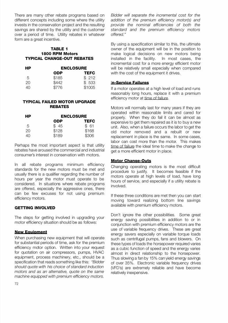
8/20/2019 Elctric Motors BALDOR
http://slidepdf.com/reader/full/elctric-motors-baldor 78/124
72
There are many other rebate programs based ondifferent concepts including some where the utilityinvests in the conservation project and the resultingsavings are shared by the utility and the customerover a period of time. Utility rebates in whateverform are a great incentive.
TABLE 1
1800 RPM Motors
TYPICAL CHANGE-OUT REBATES
HP ENCLOSURE
ODP TEFC
5 $185 $ 21220 $442 $ 53340 $776 $1005
TYPICAL FAILED MOTOR UPGRADE
REBATES
HP ENCLOSURE
ODP TEFC
5 $ 45 $ 6120 $128 $16840 $189 $306
Perhaps the most important aspect is that utilityrebates have aroused the commercial and industrialconsumer’s interest in conservation with motors.
In all rebate programs minimum efficiency
standards for the new motors must be met andusually there is a qualifier regarding the number of hours per year the motor must operate to beconsidered. In situations where rebate programsare offered, especially the aggressive ones, therecan be few excuses for not using premiumefficiency motors.
GETTING INVOLVED
The steps for getting involved in upgrading yourmotor efficiency situation should be as follows:
New Equipment
When purchasing new equipment that will operatefor substantial periods of time, ask for the premiumefficiency motor option. Written into your requestfor quotation on air compressors, pumps, HVACequipment, process machinery, etc., should be aspecification that reads something like this: “ Bidder
should quote with his choice of standard induction
motors and as an alternative, quote on the same
machine equipped with premium efficiency motors.
Bidder will separate the incremental cost for the
addition of the premium efficiency motor(s) and
provide the nominal efficiencies of both the
standard and the premium efficiency motors
offered.”
By using a specification similar to this, the ultimateowner of the equipment will be in the position tomake logical decisions on new motors beinginstalled in the facility. In most cases, theincremental cost for a more energy efficient motorwill be relatively small especially when comparedwith the cost of the equipment it drives.
In-Service Failures
If a motor operates at a high level of load and runsreasonably long hours, replace it with a premiumefficiency motor at time of failure.
Motors will normally last for many years if they are
operated within reasonable limits and cared forproperly. When they do fail it can be almost asexpensive to get them repaired as it is to buy a newunit. Also, when a failure occurs the labor to get theold motor removed and a rebuilt or newreplacement in place is the same. In some cases,labor can cost more than the motor. This makestime of failure the ideal time to make the change toget a more efficient motor in place.
Motor Change-Outs
Changing operating motors is the most difficultprocedure to justify. It becomes feasible if themotors operate at high levels of load, have longhours of service, and especially if a utility rebate isinvolved.
If these three conditions are met then you can startmoving toward realizing bottom line savingsavailable with premium efficiency motors.
Don’t ignore the other possibilities. Some greatenergy saving possibilities in addition to or in
conjunction with premium efficiency motors are theuse of variable frequency drives. These are greatenergy savers especially on variable torque loadssuch as centrifugal pumps, fans and blowers. Onthese types of loads the horsepower required variesas a cubic function of speed and the energy variesalmost in direct relationship to the horsepower.
Thus slowing a fan by 15% can yield energy savingsof over 35%. Electronic variable frequency drives(VFD’s) are extremely reliable and have becomerelatively inexpensive.

8/20/2019 Elctric Motors BALDOR
http://slidepdf.com/reader/full/elctric-motors-baldor 79/124
73
Two speed motors also offer a simple andeconomical way to reduce energy costs. Thespeeds are not infinitely adjustable as they are withadjustable frequency drives, but in many situationsthat degree of adjustment is not necessary, thesimplicity and economy of the two speed motorand its control can yield great savings.
Don’t ignore the opportunities with small motors.Many motor users in “light industry” andcommercial facilities do not recognize theopportunity to save energy because they are of theopinion that their motors are “too small” to be viablecandidates for efficiency upgrades. That thoughtprocess couldn’t be more wrong! The degree of efficiency improvement on motors less than 10 HPis substantially more than it is on larger units. Forexample, the efficiency improvement between astandard 3 HP motor and a premium efficiency 3HP motor might be 7 or 8%.
Comparing it in the same way with a 100 HP motorthe efficiency gain might be only 2%. The net resultis that small motors have the potential for paying off their differential cost faster than large motors.
OPERATING COSTS AND SAVINGS
Rule of Thumb
To get some perspective on the costs to operatemotors and some possible savings, here is a good“Rule of Thumb”.
At 5 cents per kilowatt hour it costs $1 perhorsepower per day to operate a motor at full load.(At 10 cents per kilowatt hour this doubles to $2 perday.) This value can be ratioed to reflect less thanfull load or less than continuous operation, etc.
Consider a 100 HP motor operating continuously ina 10 cents per kilowatt hour area. The annual costof operation comes out to be approximately$70,000. This can represent about 25 times thefirst cost of the motor. By spending an extra 30%($750) to get a premium efficiency unit (2.4% moreefficient) the annual operating cost could bereduced by approximately $1800.
In the case of a small 3 HP motor at 10 cents perkilowatt hour, the annual operating cost would beover $2300 per year and an extra 40% spent on themotor could reduce the operating cost by $140 peryear. In both cases mentioned, the extra cost of themotor would be paid off by energy savings in a fewmonths.
When motors are running continuously at or nearfull load the initial cost of the motor is usually of littleconsequence compared with the annual operatingcost.
OTHER BENEFITS
Because of their reduced losses, premiumefficiency motors run at lower temperatures thanequivalent standard motors. This results in longerinsulation and lubricant life and less downtimeInherent in their design is the ability to tolerate widervoltage variations and when necessary, higherambient temperatures.
An additional benefit is that by generating lesswaste heat in the space around the motor, buildingventilation and/or air conditioning requirements arereduced. This can result in additional savings.
SUMMARY
At the present time electric energy costs are high,but stable. Conservation has reduced the need fornew generating facilities and the prices of fuelshave been relatively constant. However, manynuclear plants are approaching the end of theiruseful life. As they are retired and their capacity hasto be replaced, capital costs will certainly rise. Alsoas the demand for clean burning gas, liquid andsolid fuels increases, the cost of these fuels iscertain to rise. Thus it is important to seize every
reasonable opportunity to conserve now. Adoptionof premium efficiency three phase induction motorsis an easy and cost effective way to conserve.
(continued on next page)

8/20/2019 Elctric Motors BALDOR
http://slidepdf.com/reader/full/elctric-motors-baldor 80/124
74
OPERATING COST FORMULAS
MOTORS
Kilowatt Hours = HP** x .746 x Hours of OperationMotor Efficiency
** Average Load HP (May be lower than motornameplate HP)
Useful Constants
Average hours per month = 730Hours per year = 8760
Average hours of darkness per year = 4000 Approximate average hours per month
(single shift operation) = 200
Annual Savings Formula
S = 0.746 x HP x C x N 1 _ 1
[ ES EPE
]S = Dollars saved per yearHP = Horsepower required by loadC = Energy cost in dollars per kilowatt hourN = Annual running hoursES = Efficiency of standard motor (decimal)EPE = Efficiency of premium motor (decimal)
General Formula - All Loads
Kilowatt Hours = Watts x Hours of Operation
1000
Approximate Operating Cost* =
Kilowatt Hours x AverageCost per Kilowatt Hour
* Does not include power factor penalty or demandcharges which may be applicable in some areas.

8/20/2019 Elctric Motors BALDOR
http://slidepdf.com/reader/full/elctric-motors-baldor 81/124
75
PREMIUM EFFICIENCY MOTORS – (Q & A)
In spite of the great money and energy saving potential available by using premium efficiency motors, it isamazing that so few motor users are buying these motors. Some reasons for not using them aremisunderstandings about the energy saving potential. The following information is presented in aquestion and answer format to address some of the myths and questions related to premium efficiencymotors.
Question: Can I save money even when I only have relatively small motors in my plant?
Answer: The energy saving potential of small premium efficiency motors is actually greaterpercentage-wise than the savings on large motors. The reason is that on small motors,the percentage difference in efficiency between the standard motor and the premiumefficiency motor is actually much greater than it is on larger motors. For example, thedifference between a standard motor at 3 HP and the premium efficiency motor couldeasily be 9 or more percentage points. Compare this to a 100 HP motor where thedifference between the standard and premium efficiency motors might only be 2%.
Question: Do my motors have to be fully loaded to realize the savings available in premium efficiency
motors?
Answer: It is usually advantageous to have motors loaded to more than 50% of rated load foroptimum efficiency. Thus, it is usually best to resize a motor at the same time it isupgraded to premium efficiency. However, even if this is not done and the motor isoversized, there is still substantial savings to be gained by utilizing a premium efficiencymotor. For example, at 25% of rated load, the difference in efficiency between a standardmotor and a premium efficiency motor (of 10 HP) would be 80.4% vs. 86.6%. Thus, thepremium efficiency motor is still substantially better even at low load levels than a non-premium efficiency motor. Even without resizing, a substantial efficiency improvement canbe made.
Question: How much more do premium efficiency motors cost?
Answer: Generally, premium efficiency motors cost 20 to 30% more depending upon the size andspeed of the motor.
Question: Why do premium efficiency motors cost more than standard motors?
Answer: Premium efficiency motors use more and better materials. For example, the laminationmaterial is a higher grade, higher cost steel. In addition, the rotor and stator are generallylonger in a premium efficiency motor than in a standard motor. The laminations are thinnercompared to a standard efficiency motor. This means there are more laminations. In
addition, the lamination slots are larger so more copper can be used in the windings.Finally, premium efficiency motors are manufactured in smaller production lots which alsotends to make them more expensive.
Question: If premium efficiency motors can save lots of money, why don’t more people use them?
Answer: This is a tough question but is probably related to the fact that many people buy on firstcost rather than considering operating costs. Also, there seems to be skepticism aboutmanufacturer’s claims on performance of these motors. Many power users that have beenvery active in other energy conserving programs such as lighting, insulating etc., haveignored the energy-saving potential of premium efficiency motors.

8/20/2019 Elctric Motors BALDOR
http://slidepdf.com/reader/full/elctric-motors-baldor 82/124
76
Question: Why can’t motor manufacturers make it more obvious that we are going to save money
with these motors?
Answer: Unlike light bulbs that are sold by wattage consumption (input), electric motors are sold byhorsepower (output). Thus, subtle differences in efficiency usually appear in the fine printand get overlooked. For example, it is obvious when you buy a 34 watt fluorescent lightbulb to replace a 40 watt bulb, that some savings are available. It is less obvious whenyou buy a 5 HP motor of one design versus a 5 HP motor of a premium efficiency design,that there will be savings on the electric bill. Also, the vagaries of electric bills and the
complications involved in the electric billing process with demand charges, energycharges, fuel cost adjustments and occasionally, power factor penalties, create enoughconfusion so savings are not obvious. But they exist.
Question: How can I evaluate the dollar savings on premium efficiency motors?
Answer: There are three items needed to conduct an evaluation. First and most important, is theaverage cost per kilowatt hour of electricity. The simplest and most direct way to get thisis to take the bottom line cost on a monthly electric bill and divide it by the total kilowatthours used. This gives a net cost per kilowatt hour which is generally the best cost to usein evaluating energy saving equipment. The reason this works is that equipment designed
for better efficiency will in general, reduce the demand, kilowatt hours, and fuel costadjustments in equal proportions. Thus, using the average cost per kilowatt hour is theeasiest way of making an evaluation. Next would be the HP size of the motor that isoperating and, finally, the number of hours per month or year that it operates. With thesethree items and the efficiency difference between one motor and the other, it is easy tofigure the cost savings. The formulas for doing this are readily available. If in doubt, let ushave the information and we’ll make the calculations for you.
Question: How quickly will these motors pay for themselves?
Answer: This is impossible to answer without all the facts from the previous question but motorsoperating twenty-four hours a day at or near full load, can be expected to pay forthemselves in less than two years. The difference between a standard motor’s cost and apremium efficiency motor’s cost can be paid off in a few months. One thing is certain:regardless of the operating details, premium efficiency motors will always save moneyversus lower efficiency units and savings go on for as long as the motor is in operation. Inmany cases this could be twenty to thirty years. Also, as power costs rise, savings will risein proportion. The old rule of “pay me now or pay me later” has a corollary when appliedto premium efficiency motors which might be “pay a little more now and save some nowand more later.”
Question: Are there any other advantages to premium efficiency motors?
Answer: Yes, because of the superior designs and better materials used in them, premiumefficiency motors tend to run at lower operating temperatures resulting in longer life forlubricants, bearings and motor insulation. Another advantage is that, by generating lesswaste and less heat in the space around the motor, air conditioning and ventilationrequirements are reduced, resulting in additional energy savings.
8/20/2019 Elctric Motors BALDOR
http://slidepdf.com/reader/full/elctric-motors-baldor 83/124
77
Question: What is the best way to take advantage of premium efficiency savings potential?
Answer: Specify the use of premium efficiency motors on new equipment and as replacementunits for failures. Some judgement should be used on blanket specifications. For example,it may be impractical to try to specify premium efficiency motors for single phase,fractional horsepower, and specialized motor requirements or where the motor is anintegral part of the equipment. Also, on motor installations where infrequent service isrequired, the extra cost may not be justified. Examples of this would be trash compactors,batch mixers and other equipment that only operate for short periods of time. It might
also be difficult to justify the added cost of premium efficiency motors on equipment thatoperates on a seasonal basis, especially if the season is short.
In summary, it is important to seize the opportunity to move into premium efficiency motor use as soonas possible. If you have questions not covered above, please give us a call. We’ll get you the answers.

8/20/2019 Elctric Motors BALDOR
http://slidepdf.com/reader/full/elctric-motors-baldor 84/124
78

8/20/2019 Elctric Motors BALDOR
http://slidepdf.com/reader/full/elctric-motors-baldor 85/124
79
AMPS, WATTS, POWER FACTOR AND EFFICIENCY
WHAT DO YOU REALLY PAY FOR?
INTRODUCTION
There seems to be a great deal of confusion among the users of electric motors regarding the relative
importance of power factor, efficiency and amperage, as related to operating cost. The followinginformation should help to put these terms into proper perspective.
At the risk of treating these items in reverse order, it might be helpful to understand that in an electric bill,commercial, industrial or residential, the basic unit of measurement is the kilowatt hour. This is a measureof the amount of energy that is delivered. In many respects, the kilowatt hour could be compared to aton of coal, a cubic foot of natural gas, or a gallon of gasoline, in that it is a basic energy unit. Thekilowatt hour is not directly related to amperes, and at no place on an electric bill will you find anyreference to the amperes that have been utilized. It is vitally important to note this distinction. You arebilled for kilowatt hours: you do not necessarily pay for amperes.
POWER FACTORPerhaps the greatest confusion arises due to the fact that early in our science educations, we were toldthat the formula for watts was amps times volts. This formula, watts = amps x volts, is perfectly true fordirect current circuits. It also works on some AC loads such as incandescent light bulbs, quartz heaters,electric range heating elements, and other equipment of this general nature. However, when the loadsinvolve a characteristic called inductance, the formula has to be altered to include a new term calledpower factor. Thus, the new formula for single phase loads becomes, watts are equal to amps x volts xpower factor. The new term, power factor, is always involved in applications where AC power is usedand inductive magnetic elements exist in the circuit. Inductive elements are magnetic devices such assolenoid coils, motor windings, transformer windings, fluorescent lamp ballasts, and similar equipmentthat have magnetic components as part of their design.
Looking at the electrical flow into this type of device, we would find that there are, in essence, twocomponents. One portion is absorbed and utilized to do useful work. This portion is called the realpower. The second portion is literally borrowed from the power company and used to magnetize themagnetic portion of the circuit. Due to the reversing nature of AC power, this borrowed power issubsequently returned to the power system when the AC cycle reverses. This borrowing and returningoccurs on a continuous basis. Power factor then becomes a measurement of the amount of real powerthat is used, divided by the total amount of power, both borrowed and used. Values for power factor willrange from zero to 1.0. If all the power is borrowed and returned with none being used, the power factorwould be zero. If on the other hand, all of the power drawn from the power line is utilized and none isreturned, the power factor becomes 1.0. In the case of electric heating elements, incandescent lightbulbs, etc., the power factor is 1.0. In the case of electric motors, the power factor is variable andchanges with the amount of load that is applied to the motor. Thus, a motor running on a work bench,with no load applied to the shaft, will have a low power factor (perhaps .1 or 10%), and a motor runningat full load, connected to a pump or a fan might have a relatively high power factor (perhaps .88 or 88%).Between the no load point and the full load point, the power factor increases steadily with thehorsepower loading that is applied to the motor. These trends can be seen on the typical motorperformance data plots which are shown in figure 1.

8/20/2019 Elctric Motors BALDOR
http://slidepdf.com/reader/full/elctric-motors-baldor 86/124
80
EFFICIENCY
Now, let’s consider one of the most critical elements involved in motor operating cost. This is efficiency.Efficiency is the measure of how well the electric motor converts the power that is purchased into usefulwork. For example, an electric heater such as the element in an electric stove, converts 100% of thepower delivered into heat. In other devices such as motors, not all of the purchased energy is convertedinto usable energy. A certain portion is lost and is not recoverable because it is expended in the lossesassociated with operating the device. In an electric motor, these typical losses are the copper losses, theiron losses, and the so-called friction and windage losses associated with spinning the rotor and the
bearings and moving the cooling air through the motor.
In an energy efficient motor, the losses are reduced by using designs that employ better grades of material, more material and better designs, to minimize the various items that contribute to the losses inthe motor.
For example, on a 10 HP motor, a Super E energy efficient design might have a full load efficiency of 91.7%, meaning that, at full load (10 HP), it converts 91.7% of the energy it receives into useful work. A less efficient motor might have an efficiency of 82%, which would indicate that it only converts 82% of the power into useful work.
In general, the efficiency of motors will be relatively constant from 50% to 100% of rated load.
AMPERES
Now, let’s discuss amperes. Amperes are an indication of the flow of electric current into the motor. Thisflow includes both the borrowed as well as the used power. At low load levels, the borrowed power is ahigh percentage of the total power. As the load increases on the motor, the borrowed power becomesless and less of a factor and the used power becomes greater. Thus, there is an increase in the powerfactor as the load on the motor increases. As the load continues to increase beyond 50% of the rating of the motor, the amperage starts to increase in a nearly straight line relationship. This can be seen in figure 1.
SUMMARY
Figure 1 shows significant items that have been discussed as plots of efficiency, power factor and watts, as
they relate to horsepower. The most significant factor of all these is the watts requirement of the motor forthe various load levels because it is the watts that will determine the operating cost of the motor, not theamperage.
The customer that has an extremely low power factor in the total plant electrical system, may be penalizedby his utility company because he is effectively borrowing a great deal of power without paying for it. Whenthis type of charge is levied on the customer, it is generally called a power factor penalty. In general, powerfactor penalties are levied only on large industrial customers and rarely on smaller customers regardless of their power factor. In addition, there are a great many types of power customers such as commercialestablishments, hospitals, and some industrial plants that inherently run at very high power factors. Thus,the power factor of individual small motors that are added to the system, will not have any significant effecton the total plant power factor.
It is for this reasons that the blanket statement can be made, that increasing motor efficiency will reducethe kilowatt hour consumption and the power cost for all classes of power users, regardless of theirparticular rate structure or power factor situation. This same type of statement cannot be made relative topower factor.

8/20/2019 Elctric Motors BALDOR
http://slidepdf.com/reader/full/elctric-motors-baldor 87/124
81
Figure 1
% E
F F I C I E N C Y A N D P O W E R F
A C T O R

8/20/2019 Elctric Motors BALDOR
http://slidepdf.com/reader/full/elctric-motors-baldor 88/124
82
The following basic equations are useful in understanding and calculating the factors that determine theoperating costs of motors and other types of electrical equipment.
OPERATING COST CALCULATIONS
MOTORS
HP** x .746 x Hours of OperationKilowatt Hours =
Motor Efficiency
** Average Load HP (May be lower than Motor Nameplate HP)
General Formula All Loads
Kilowatt Hours = Watts x Hours of Operation1000
Approximate Operating Cost* = Kilowatt hours x Average Cost per Kilowatt Hour
* Does not include power factor penalty or demand charges which maybe applicable in some areas.
Useful Constants
Average Hours per Month = 730
Average Hours per Year = 8760
Average Hours of Darkness per Year = 4000
Approximate Average Hours per Month(Single Shift Operation) = 200

8/20/2019 Elctric Motors BALDOR
http://slidepdf.com/reader/full/elctric-motors-baldor 89/124
83
APPROXIMATE LOAD DATA FROM AMPERAGE READINGS
CONDITIONS
1. Applied voltage must be within 5% of nameplate rating.
2. You must be able to disconnect the motor from the load.(By removing V-belts or disconnecting a coupling).
3. Motor must be 7-1/2 HP or larger, 3450, 1725, or 1140 RPM.
4. The indicated line amperage must be below the full load nameplate rating.
PROCEDURE
1. Measure and record line amperage with load connected and running.
2. Disconnect motor from load. Measure and record the line amperage when the motor is runningwithout load.
3. Read and record the motor’s nameplate amperage for the voltage being used.
4. Insert the recorded values in the following formula and solve.
(2 x LLA) – NLA% Rated HP = X 100
(2 x NPA) – NLA
Where:
LLA = Loaded Line Amps
NLA = No Load Line Amps(Motor disconnected from load)
NPA = Nameplate Amperage(For operating voltage)
Please Note: This procedure will generally yield reasonably accurate results when motor load isin the 40 to 100% range and deteriorating results at loads below 40%.
FOR AN EXAMPLE AND SAMPLE CALCULATION, SEE NEXT PAGE

8/20/2019 Elctric Motors BALDOR
http://slidepdf.com/reader/full/elctric-motors-baldor 90/124
84
Approximate Load Data from Amperage Readings
Example:
A 20 HP motor driving a pump is operating on 460 volts and has a loaded line amperage of 16.5.
When the coupling is disconnected and the motor is operated at no load the amperage is 9.3.
The motor nameplate amperage for 460 volts is 19.4.
Therefore we have:
Loaded Line Amps LLA = 16.5
No Load Amps NLA = 9.3
Nameplate Amps NPA = 19.4
(2 X 16.5) – 9.3 23.7% Rated HP = X 100 = X 100 = 80.3%
(2 X 19.4) – 9.3 29.5
Approximate load on motor slightly over 16 HP.
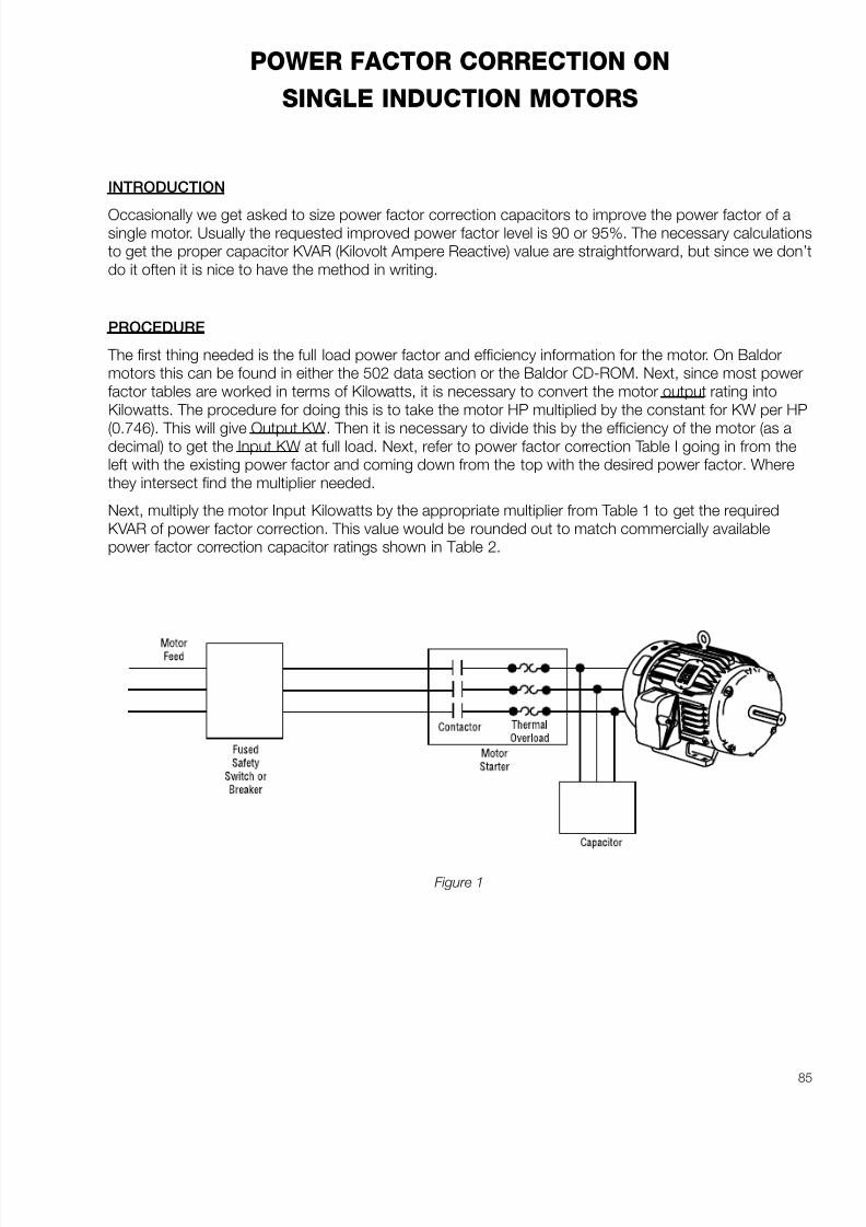
8/20/2019 Elctric Motors BALDOR
http://slidepdf.com/reader/full/elctric-motors-baldor 91/124
85
POWER FACTOR CORRECTION ON
SINGLE INDUCTION MOTORS
INTRODUCTION
Occasionally we get asked to size power factor correction capacitors to improve the power factor of asingle motor. Usually the requested improved power factor level is 90 or 95%. The necessary calculationsto get the proper capacitor KVAR (Kilovolt Ampere Reactive) value are straightforward, but since we don’tdo it often it is nice to have the method in writing.
PROCEDURE
The first thing needed is the full load power factor and efficiency information for the motor. On Baldormotors this can be found in either the 502 data section or the Baldor CD-ROM. Next, since most powerfactor tables are worked in terms of Kilowatts, it is necessary to convert the motor output rating intoKilowatts. The procedure for doing this is to take the motor HP multiplied by the constant for KW per HP
(0.746). This will give Output KW. Then it is necessary to divide this by the efficiency of the motor (as adecimal) to get the Input KW at full load. Next, refer to power factor correction Table I going in from theleft with the existing power factor and coming down from the top with the desired power factor. Wherethey intersect find the multiplier needed.
Next, multiply the motor Input Kilowatts by the appropriate multiplier from Table 1 to get the requiredKVAR of power factor correction. This value would be rounded out to match commercially availablepower factor correction capacitor ratings shown in Table 2.
Figure 1

8/20/2019 Elctric Motors BALDOR
http://slidepdf.com/reader/full/elctric-motors-baldor 92/124
86
TABLE 1
ORIGINAL DESIRED POWER FACTOR %
FACTOR %85 90 95
60 0.713 0.849 1.004
62 0.646 0.782 0.937
64 0.581 0.717 0.872
66 0.518 0.654 0.80968 0.458 0.594 0.749
70 0.400 0.536 0.691
72 0.344 0.480 0.635
74 0.289 0.425 0.580
76 0.235 0.371 0.526
77 0.209 0.345 0.500
78 0.182 0.318 0.473
79 0.156 0.292 0.447
80 0.130 0.266 0.421
81 0.104 0.240 0.395
82 0.078 0.214 0.369
83 0.052 0.188 0.343
84 0.026 0.162 0.317
85 0.000 0.136 0.291
86 0.109 0.264
87 0.083 0.238
88 0.056 0.211
89 0.028 0.183
90 0.000 0.15591 0.127
92 0.097
93 0.066
94 0.034
95 0.000

8/20/2019 Elctric Motors BALDOR
http://slidepdf.com/reader/full/elctric-motors-baldor 93/124
87
TABLE 2
3-PHASE STANDARD CAPACITOR RATINGS
KVAR (Kilovolt Amperes Reactive)
1.0 20.0 70.0
1.5 22.5 75.0
2.0 25.0 80.0
2.5 27.5 85.0
3.0 30.0 90.0
4.0 32.5 100.0
5.0 35.0 120.0
6.0 37.5 140.0
7.5 40.0 150.0
8.0 42.5 160.0
9.0 45.0 180.0
10.0 50.0 200.011.0 52.5 225.0
12.5 55.0 250.0
15.0 60.0 300.0
17.5 65.0 350.0
EXAMPLE:
To illustrate the procedure an example is worked as follows:
What is the KVAR of power factor correction capacitors needed to improve the power factor of a
catalog number M2555T, 100 HP motor, to 95% at full load?
Step 1: Look up the existing power factor and efficiency Efficiency = 94.1%Power Factor = 85%
Step 2: Convert the HP to Kilowatts output . 100 HP x 0.746 = 74.6 KW
Step 3: Convert Kilowatts output to Kilowatts input by dividing by the full load efficiency.
74.6 = 79.3 KW Input.941
Step 4: Look in Table 1 to find the multiplier to achieve the desired 95% corrected power factor. The multiplier is 0.291.
Step 5: Multiply Input KW by this multiplier. 79.3 x 0.291 = 23.1 KVAR
This gives the required Capacitor KVAR.
Step 6: Select closest value from Table 2. 22.5 KVAR
The voltage of the capacitor would also have to be specified. In this case it would be 480 volts.
8/20/2019 Elctric Motors BALDOR
http://slidepdf.com/reader/full/elctric-motors-baldor 94/124
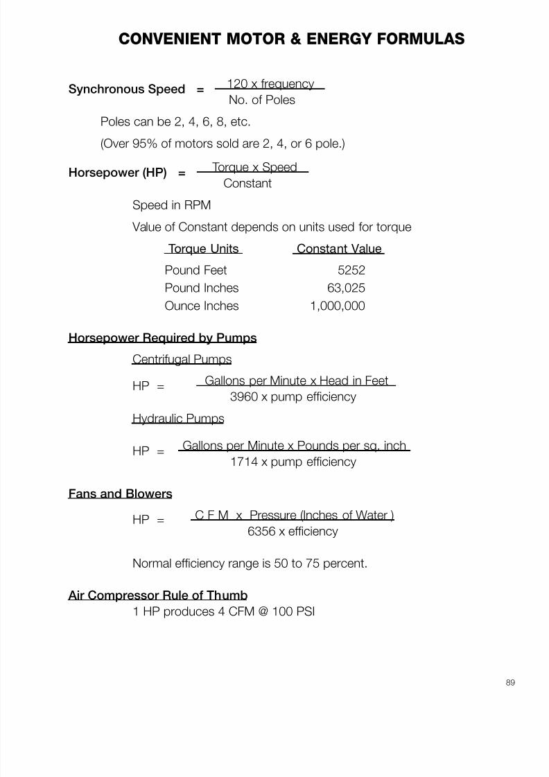
8/20/2019 Elctric Motors BALDOR
http://slidepdf.com/reader/full/elctric-motors-baldor 95/124
89
CONVENIENT MOTOR & ENERGY FORMULAS
Synchronous Speed = 120 x frequency
No. of Poles
Poles can be 2, 4, 6, 8, etc.
(Over 95% of motors sold are 2, 4, or 6 pole.)
Horsepower (HP) = Torque x Speed
Constant
Speed in RPM
Value of Constant depends on units used for torque
Torque Units Constant Value
Pound Feet 5252Pound Inches 63,025
Ounce Inches 1,000,000
Horsepower Required by Pumps
Centrifugal Pumps
HP = Gallons per Minute x Head in Feet
3960 x pump efficiency
Hydraulic Pumps
HP = Gallons per Minute x Pounds per sq. inch
1714 x pump efficiency
Fans and Blowers
HP = C F M x Pressure (Inches of Water )
6356 x efficiency
Normal efficiency range is 50 to 75 percent.
Air Compressor Rule of Thumb
1 HP produces 4 CFM @ 100 PSI

8/20/2019 Elctric Motors BALDOR
http://slidepdf.com/reader/full/elctric-motors-baldor 96/124

8/20/2019 Elctric Motors BALDOR
http://slidepdf.com/reader/full/elctric-motors-baldor 97/124
91
HORSEPOWER CALCULATIONS FOR SPEED CHANGES
ON
VARIABLE TORQUE LOADS
(Fans, Blowers, & Centrifugal Pumps)
HPnew = HPoriginal x Speed New 3
( Speed Original )
Example:
Original HP = 7.5
Original Blower Speed 900 RPM
New Blower Speed 750 RPM
Determine new HP
HPnew = 7.5 x 750 3or 7.5 x 750 x 750 x 750 =( 900 ) 900 900 900
7.5 x .83 x .83 x .83 =
7.5 x .57 = 4.3 HP
Note: Driving Energy Requirement (Watts) go up and down at approximately the
same rate as HP.

8/20/2019 Elctric Motors BALDOR
http://slidepdf.com/reader/full/elctric-motors-baldor 98/124
92

8/20/2019 Elctric Motors BALDOR
http://slidepdf.com/reader/full/elctric-motors-baldor 99/124
93
HOW TO SELECT MOTORS FOR
HAZARDOUS LOCATIONSBy Edward Cowern, P.E.,

8/20/2019 Elctric Motors BALDOR
http://slidepdf.com/reader/full/elctric-motors-baldor 100/124
94
How To Select Motors for
Hazardous Locations
By EDWARD COWERN, P.E.
AILURE TO SPECIFY the proper motor for usein a hazardous location can have serious
consequences — lost production, extensive propertydamage, and even loss of human life. Selection of theproper motor requires an understanding of underwriters’ Laboratories’ (UL) and NationalElectrical Code (NEC) Class, Group and Divisiondesignations and the T code letters.
In some plant engineering departments, there maybe only a vague understanding of the selection criteriaof motors for hazardous locations. In some cases, thespecifier passes the buck to another party in the hopethat someone — perhaps the motor manufacturer —will fill in the missing specification data. In other cases,the same type of motor that had been used in the plantpreviously is specified, with the hope that this approachwill certainly handle any situation. But this approachcan greatly increase the cost of the project, and, insome cases, result in a motor that is inadequate for theapplication.
Hazardous locations are operating environments inwhich explosive or ignitable vapors or dust is present,or is likely to become present. Special motors arerequired to ensure that any internal fault in the motorwill not ignite the vapor or dust. Requirements for
electrical installations in hazardous locations arecovered in Articles 500, 501, 502, 503, 510, 511, 513,514, 515, and 516 of the National Electrical Code.
A relatively new article 505 makes an abrupt changein traditional hazardous location requirements andbrings the NEC closer to the somewhat less stringentEuropean code requirements by classifying areas intothree separate zones 0, 1 and 2. This section tends toinvolve wiring practices and components rather thanmotors so it will not be included in the discussion tofollow.
At the present time article 505 sets forth some
principles, but it will be some time before equipmentsuppliers will have products available to match the newrequirements. We can also expect the “inertia of habit”to slow the change to the somewhat relaxed zonerequirements. Perhaps the changes will be used first bymultinational companies where engineers are morefamiliar with the zone system and matching hardware.
The term “explosion proof” is often erroneouslythought to apply to any hazardous-location motor.Explosion proof motors, however, are only thoseapproved for Class I locations — that is, where
potentially explosive gases or vapors are present. AClass I unit is constructed to contain an explosion
within itself without rupturing. After the initialpressure buildup on ignition, the hot gas is forced tocool by passing through long, tight passageways (flamepaths) before escaping from the motor. the temperatureof gas escaping from the motor will then be below theminimum ignition temperature (MIT) of the gases of vapors in the atmosphere surrounding the motor.
Meaning of Motor “Class” Designations — Everymotor approved for hazardous locations carries anUnderwriters’ Laboratories’ nameplate that indicatesthe motor is approved for hazardous locations (seeillustration). This nameplate identifies the motor as
having been designed for operation in Class I or ClassII locations. Some motors may be approved for bothClass I and II locations.
Basically, the Class identifies the physicalcharacteristics of the hazardous materials present at thelocation where the motor will be used. Class I coversgases, vapors, or liquids that are explosive or else posea threat as ignitable mixtures. A familiar example of aClass I material is gasoline. It is explosive as a vaporand ignitable as a liquid. Some of the most commonClass I substances are listed in Table 1.
Class II covers dusts — specifically, dust in amountssufficient to create explosive mixtures, and dusts thatare electrically conductive. A prime example of ahazardous dust is wheat flour. As a compact mass, flourburns or smolders; but when it is finely distributed inair, it is highly explosive. Also included in Class II areelectrically conductive metallic and nonmetallic dusts,such as powdered aluminum and magnesium, andpulverized coal. Aluminum and magnesium dusts canburn violently even when not suspended in air; butwhen airborne, they are explosive. Some commonClass II substances are listed in Table 2.
F An Underwriters' Laboratory name-plate is used on all motors approved
for use in Division 1 hazardouslocations. In addition to the normalmotor data such as horsepower,speed, voltage, amperage, NEMA Code Letter, etc. it also shows thespecific Class(es) and Group(s) forwhich the motor is approved. In theexample shown the motor isapproved for Class I Group D andClass II Groups F and G. The T code is also indicated.

8/20/2019 Elctric Motors BALDOR
http://slidepdf.com/reader/full/elctric-motors-baldor 101/124
95
Class III locations do not normally requirehazardous-location motors. Specifying a hazardous-location motor for Class III locations is a commonerror. Section 503-6 of the NEC permits a totallyenclosed fan-cooled or nonventilated motor to be usedin Class III locations. A totally enclosed motor can bepurchased at lower cost than a motor approved forhazardous locations. NEC Section 503-6 also allowsthe use of an open drip-proof motor in Class III
locations, if the inspection authority is satisfied thatproper housekeeping will be maintained. Class IIIlocations are those where easily ignitable fibers and“flyings” are likely to be present. Such substances arecommonly encountered in the textile, woodworking,and plastics industries. Class III materials are notnormally airborne, because they are fairly heavy andsettle rapidly. They are, however, quite flammable, and,therefore, create a potentially hazardous conditionwhen near electrical equipment. Common Class IIIsubstances are listed in Table 3.
Meaning of “Group” Designations — Within
Class I and Class II, Group designations are assigned tovarious combustible substances on the basis of theirbehavior after ignition. Group designations A throughG are arranged in descending order according to thestringency of motor design requirements; Group Arequirements would require the longest flame pathsand tightest fits. Groups A through D fall within ClassI, and Groups E, F, and G fall within Class II. Class IIImaterials are not broken down by group.
Gasoline and acetylene provide an illustration of thegroup concept. Both are Class I substances. Acetyleneis designated as a Group A substance, gasoline fallswithin Group D. MIT of automotive gasoline is 280˚ C(536˚ F), slightly below the 305˚ C (581˚ F) MIT of acetylene. An acetylene explosion, however, is moreintense than a gasoline explosion, so acetylene isgrouped well above gasoline.
It is a common misconception that Class Itranscends Class II and that a Class I motor willautomatically satisfy any Class II requirement. But, aClass I motor is designed primarily to confine theeffects of an internal motor explosion. Design is basedon the assumption that, over a period of time, normal
heating and cooling will cause the motor to breathe thesurrounding atmosphere, and the atmosphere withinthe motor will, eventually, become the same as that of the operating environment. A subsequent internal faultcan, therefore, cause an explosion within the motor.
A Class II motor, however, is designed to maintainthe motor’s surface temperature at a level such that Class
II materials in the motor operating environment will notbe heated to their MIT. If the operating environmentcontains both Class I and Class II substances, a dual-rated Class I/Class II motor must be specified.
Another common misconception is that because theClasses and Groups exist — then there should besuitable products (motors or other equipment) tooperate in the defined environment. As it turns out,Classes and Groups are used for all types of equipmentincluding enclosures, light fixtures, heating elements,operator devices, etc. But just because there is adefinition it doesn’t mean that a matching product isavailable. In the case of motors this is especially true
for Class I Groups A and B. Apparently the market formotors to operate in these environments is so limited,
TABLE I, CLASS I SUBSTANCES AND ATMOSPHERES
Minimum Ignition
Substance or Atmosphere Temperature
Group A
acetylene 305 ˚ C (581 ˚ F)
Group B
butadiene 420 ˚ C (788 ˚ F)ethylene oxide 570 ˚ C (1058 ˚ F)hydrogen 500 ˚ C (932 ˚ F)
Group C
acetaldehyde 175 ˚ C (347 ˚ F)cyclopropane 498 ˚ C (928 ˚ F)diethyl ether 180 ˚ C (356 ˚ F)ethylene 450 ˚ C (842 ˚ F)isoprene 395 ˚ C (743 ˚ F)unsymmetrical dimethyl hydrazine(UDMH) 1, 1-dimethyl hydrazine) 249 ˚ C (480 ˚ F)
Group D
acetone 465 ˚ C (869 ˚ F)acrylonitrile 481 ˚ C (898 ˚ F)ammonia 651 ˚ C (1204 ˚ F)benzene 498 ˚ C (928 ˚ F)butane 287 ˚ C (550 ˚ F)1-butanol (butyl alcohol) 343 ˚ C (650 ˚ F)
2-butanol (secondary butyl alcohol) 405 ˚ C (761 ˚ F)n-butyl acetate 425 ˚ C (797 ˚ F)isobutyl acetate 421 ˚ C (790 ˚ F)ethane 472 ˚ C (882 ˚ F)ethanol (ethyl alcohol) 363 ˚ C (685 ˚ F)ethyl acetate 426 ˚ C (800 ˚ F)
ethylene dichloride 413 ˚ C (775 ˚ F)gasoline 280 ˚ C (536 ˚ F)heptane 204 ˚ C (399 ˚ F)hexane 225 ˚ C (437 ˚ F)methane (natural gas) 537 ˚ C (999 ˚ F)methanol (methyl alcohol) 464 ˚ C (867 ˚ F)
3-methyl-1-butanol (isoamyl alcohol) 350 ˚ C (662 ˚ F)methyl ethyl ketone 404 ˚ C (759 ˚ F)methyl isobutyl ketone 448 ˚ C (840 ˚ F)
2-methyl-1-propanol (isobutyl alcohol) 415 ˚ C (780 ˚ F)2-methyl-2-propanol (tertiary butyl alcohol) 478 ˚ C (892 ˚ F)octane 206 ˚ C (403 ˚ F)
petroleum naphtha 288 ˚ C (550 ˚ F)1-pentanol (amyl alcohol) 300 ˚ C (572 ˚ F)propane 450 ˚ C (842 ˚ F)1-propanol (propyl alcohol) 412 ˚ C (775 ˚ F)2-propanol (isopropyl alcohol) 399 ˚ C (750 ˚ F)propylene 455 ˚ C (851 ˚ F)
styrene 490 ˚ C (914 ˚ F)vinyl acetate 402 ˚ C (756 ˚ F)vinyl Chloride 472 ˚ C (882 ˚ F)p-xylene 528 ˚ C (984 ˚ F)
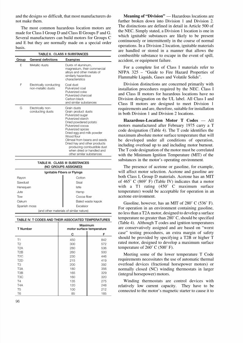
8/20/2019 Elctric Motors BALDOR
http://slidepdf.com/reader/full/elctric-motors-baldor 102/124
96
and the designs so difficult, that most manufacturers donot make them.
The most common hazardous location motors aremade for Class I Group D and Class II Groups F and G.Several manufacturers can build motors for Groups Cand E but they are normally made on a special orderbasis.
Meaning of “Division” — Hazardous locations arefurther broken down into Division 1 and Division 2.The distinctions are defined in detail in Article 500 of the NEC. Simply stated, a Division 1 location is one inwhich ignitable substances are likely to be presentcontinuously or intermittently in the course of normaloperations. In a Division 2 location, ignitable materialsare handled or stored in a manner that allows thecombustible substance to escape in the event of spill,
accident, or equipment failure.
For a complete list of Class I materials refer toNFPA 325 – “Guide to Fire Hazard Properties of Flammable Liquids, Gases and Volatile Solids”.
Division distinctions are concerned primarily withinstallation procedures required by the NEC. Class Iand Class II motors for hazardous locations have noDivision designation on the UL label. All Class I andClass II motors are designed to meet Division 1requirements and are, therefore, suitable for installationin both Division 1 and Division 2 locations.
Hazardous-Location Motor T Codes — Allmotors manufactured after February 1975 carry a Tcode designation (Table 4). The T code identifies themaximum absolute motor surface temperature that willbe developed under all conditions of operation,including overload up to and including motor burnout.The T code designation of the motor must be correlatedwith the Minimum Ignition Temperature (MIT) of thesubstances in the motor’s operating environment.
The presence of acetone or gasoline, for example,will affect motor selection. Acetone and gasoline areboth Class I, Group D materials. Acetone has an MIT
of 465˚ C (869˚ F) (Table IV) indicates that a motorwith a T1 rating (450˚ C maximum surfacetemperature) would be acceptable for operation in anacetone environment.
Gasoline, however, has an MIT of 280˚ C (536˚ F).For operation in an environment containing gasoline,no less than a T2A motor, designed to develop a surfacetemperature no greater than 280˚ C, should be specified(Table 4). Although T codes and ignition temperaturesare conservatively assigned and are based on “worstcase” testing procedures, an extra margin of safetyshould be provided by specifying a T2B or higher Trated motor, designed to develop a maximum surfacetemperature of 260˚ C (500˚ F).
Meeting some of the lower temperature T Coderequirements necessitates the use of automatic thermaloverload devices (fractional horsepower motors) ornormally closed (NC) winding thermostats in larger(integral horsepower) motors.
Winding thermostats are control devices withrelatively low current capacity. They have to beconnected to the motor’s magnetic starter to cause it to
TABLE II. CLASS II SUBSTANCES
Group General definitions Examples
E Metallic dusts Dusts of aluminum,magnesium, their commercialalloys and other metals of similarly hazardouscharacteristics
F Electrically conducting Coal dustnon-metallic dusts Pulverized coal
Pulverized cokePulverized charcoalCarbon black and similar substances
G Electrically non- Grain dustsconducting dusts Grain product dusts
Pulverized sugar
Pulverized starchDried powdered potatoPulverized cocoaPulverized spicesDried egg and milk powderWood flourOilmeal from beans and seedsDried hay and other products
producing combustible dustwhen dried or handled andother similar substances
TABLE III. CLASS III SUBSTANCES
(NO GROUPS ASSIGNED)
Ignitable Fibers or Flyings
Rayon Cotton
Sawdust Sisal
Henequen Istle
Jute Hemp
Tow Cocoa fiber
Oakum Baled waste kapok
Spanish moss Excelsior
(and other materials of similar nature)
TABLE IV. T CODES AND THEIR ASSOCIATED TEMPERATURES
MaximumT Number motor surface temperature
C F
T1 450 842 T2 300 572
T2A 280 536
T2B 260 500
T2C 230 446
T2D 215 419
T3 200 392
T3A 180 356
T3B 165 329
T3C 160 320
T4 135 275
T4A 120 248
T5 100 212
T6 85 185

8/20/2019 Elctric Motors BALDOR
http://slidepdf.com/reader/full/elctric-motors-baldor 103/124
interrupt power to the motor when the internaltemperature gets too high. Failure to make the required“control circuit” connection will negate the motornameplate T Code rating.
Additional Sources of Information — In additionto the NEC, three other publications of the NationalFire Protection Association (NFPA)* will be helpful inselecting the proper motor. NFPA publication 325,mentioned previously, covers the properties of hazardous liquids, gases, and volatile solids, andprovides a more comprehensive listing of hazardoussubstances than does Table 1. NFPA 497 —“Recommended Practice for the Classification of Flammable Liquids, Gases, or Vapors and of (Classified) Locations for Electrical Installations inChemical Process Areas” will help classifyinstallations and areas. NFPA 499 — “RecommendedPractice for the Classification of Combustible Dustsand of Hazardous (Classified) Locations for ElectricalInstallations in Chemical Process Areas” covers ClassII substances. Each publication provides MIT’s for the
substances covered in the respective publications.
The field service representative of the plant’sinsurance underwriter can also provide advice whenthere is uncertainty as to what type of motor is requiredfor a particular hazardous-location application.
*NFPA publications can be obtained from National Fire Protection
Association, 1 Batterymarch Park, P.O. Box 9101, Quincy, MA 02269-9101.
97

8/20/2019 Elctric Motors BALDOR
http://slidepdf.com/reader/full/elctric-motors-baldor 104/124
98
8/20/2019 Elctric Motors BALDOR
http://slidepdf.com/reader/full/elctric-motors-baldor 105/124
99
EXPLOSION PROOF MOTORS IN DIVISION 2 AREAS
We have found that one of the most confusing things about explosion proof requirements involves theapplication of motors in Division 2 areas.
To put things in perspective, Division 1 involves areas where hazardous liquids, vapors, gases orhazardous dusts are present a good deal of the time or even all the time in the normal course of events.Division 2 areas are where the hazardous materials are only apt to be in the area if there is a spill,
accident, loss of ventilation or some other unusual condition. the treatment of both of these divisions iscovered in Article 500 of the National Electric Code (NEC).
Once an area has been identified as being either Division 1 or Division 2, the National Electric Coderequires certain types of motors be used in those environments. Division 1 areas always requirehazardous location (explosion proof) motors having the class and group approvals that match theparticular hazardous substance in the area. Thus, for Division 1 requirements, explosion proof equipmentmust be used. On the other hand, if an area has been classified as Division 2, the National Electric Codewill frequently allow the use of totally enclosed (or even open drip proof) motors provided certainconditions are met. Basically, those conditions relate to there not being any hot surfaces or sparkingparts in the motor. For example, sparking parts could be brushes (as found in DC motors), switchingdevices (such as centrifugal switches used in many single phase motors), thermostats or thermal
overloads normally found in thermally protected motors, or space heaters that might have high surfacetemperatures.
In essence, what the code is saying is that three phase induction motors that do not have hightemperature surfaces or sparking parts will not, in normal operation, be likely to ignite the surroundingenvironment. They can be used because the likelihood of a (spark producing) failure of the motoroccurring at the same time that a spill or accident occurs is so remote it is a very unlikely event.
One way to avoid conflicts on interpretations of what is needed is to “play safe” and use hazardouslocation motors for both Division 1 and Division 2 requirements. This is a safe but expensive option andbecomes more expensive as motors get larger.
A second choice is to use three phase TEFC or even Open Drip Proof motors that meet the non-
sparking and no hot surfaces requirements for Division 2.For machinery builders or contractors who want to use the less expensive motors for Division 2requirements, it is always wise to make your intentions known to the customer in advance.
Perhaps the best way to do this would be to notify them by letter, with a statement such as follows:
“Since your stated requirement is Class * Group * , Division 2, it is our intention tosupply totally enclosed, fan cooled, three phase induction motors in accordance withParagraph (1) of the National Electric Code. If you object to this, please notify us as soon aspossible.”
By using this type of letter to make your intentions clear, it is much less likely that a dispute overinterpretation will develop at a later time.
If you should have any questions regarding this requirement, please refer to the National Electric Code forthe appropriate Section based on the class, group and division of the requirement.
* Fill in appropriate references
(1) Paragraph references
For Class I --------------------- 501-8(b)
For Class II -------------------- 502-8(b)

8/20/2019 Elctric Motors BALDOR
http://slidepdf.com/reader/full/elctric-motors-baldor 106/124
100

8/20/2019 Elctric Motors BALDOR
http://slidepdf.com/reader/full/elctric-motors-baldor 107/124
101
DC DRIVE FUNDAMENTALS
UNDERSTANDING DC DRIVES
DC motors have been available for nearly 100 years. In fact the first electric motors were designed andbuilt for operation from direct current power.
AC motors are now and will of course remain the basic prime movers for the fixed speed requirements ofindustry. Their basic simplicity, dependability and ruggedness make AC motors the natural choice for thevast majority of industrial drive applications.
Then where do DC drives fit into the industrial drive picture of the future?
In order to supply the answer, it is necessary to examine some of the basic characteristics obtainablefrom DC motors and their associated solid state controls.
1. Wide speed range.
2. Good speed regulation.
3. Compact size and light weight (relative to mechanical variable speed).4. Ease of control.
5. Low maintenance.
6. Low cost.
In order to realize how a DC drive has the capability to provide the above characteristics, the DC drivehas to be analyzed as two elements that make up the package. These two elements are of course themotor and the control. (The “control” is more accurately called the “regulator” ).
DC MOTORS
Basic DC motors as used on nearly all packaged drives have a very simple performance characteristic —the shaft turns at a speed almost directly proportional to the voltage applied to the armature. Figure 1shows a typical voltage/speed curve for a motor operating from a 115 volt control.
From the above curve you can see that with 9 volts applied to the armature, this motor would beoperating at Point 1 and turn at approximately 175 RPM. Similarly with 45 volts applied, the motor would
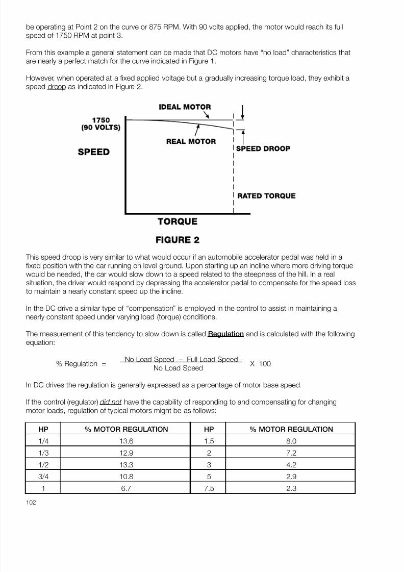
8/20/2019 Elctric Motors BALDOR
http://slidepdf.com/reader/full/elctric-motors-baldor 108/124

8/20/2019 Elctric Motors BALDOR
http://slidepdf.com/reader/full/elctric-motors-baldor 109/124
103
One other very important characteristic of a DC motor should be noted. Armature amperage is almostdirectly proportional to output torque regardless of speed. This characteristic is shown by Figure 3. Point1 indicates that a small fixed amount of current is required to turn the motor even when there is nooutput torque. This is due to the friction of the bearings, electrical losses in the motor materials and loadimposed by the air in the motor (windage).
Beyond Point 1 through Point 2 and 3, the current increases in direct proportion to the torque requiredby the load.
From this discussion and Figure 3 a general statement can be made that for PM and Shunt Woundmotors load torque determines armature amperage.
In summary, two general statements can be made relative to DC motor performance.
1. Motor Speed is primarily determined by Applied Armature Voltage.
2. Motor Torque is controlled by Armature Current (amperes).
Understanding these two concepts of DC motors provides the key to understanding total driveperformance.
REGULATORS (CONTROLS)
The control provides two basic functions:
1. It rectifies AC power converting it to DC for the DC motor.
2. It controls the DC output voltage and amperage in response to various control and feedback signals thereby regulating the motor’s performance, both in speed and torque.
RECTIFYING FUNCTION
The basic rectifying function of the control is accomplished by a combination of power semiconductors(Silicon Controlled Rectifiers and Diodes) that make up the “power bridge” assembly.

8/20/2019 Elctric Motors BALDOR
http://slidepdf.com/reader/full/elctric-motors-baldor 110/124
104
REGULATING FUNCTION
The regulating function is provided by a relatively simple electronic circuit that monitors a number of inputs and sums these signals to produce a so called “error” signal. This error signal is processed andtransformed into precisely timed pulses (bursts of electrical energy). These pulses are applied to the gatesof the SCR’s in the power bridge thereby regulating the power output to the DC motor.
For most purposes it is not necessary to understand the electronic details of the regulator, however, inorder to appreciate the regulator function it is good to understand some of the input signals that are
required to give the regulator its capabilities, these are shown diagrammatically in Figure 4.
The AC to DC power flow is a relatively simple straight through process with the power being convertedfrom AC to DC by the action of the solid state power devices that form the power bridge assembly.
The input and feedback signals need to be studied in more detail.
SET POINT INPUT
In most packaged drives this signal is derived from a closely regulated fixed voltage source applied to a
potentiometer. 10 volts is a very common reference.
The potentiometer has the capability of accepting the fixed voltage and dividing it down to any value of from, for example, 10 to zero volts, depending on where it is set. A 10 volt input to the regulator from thespeed adjustment control (potentiometer) corresponds to maximum motor speed and zero voltscorresponds to zero speed. Similarly any speed between zero and maximum can be obtained byadjusting the speed control to the appropriate setting.
8/20/2019 Elctric Motors BALDOR
http://slidepdf.com/reader/full/elctric-motors-baldor 111/124
105
SPEED FEEDBACK INFORMATION
In order to “close the loop” and control motor speed accurately it is necessary to provide the control witha feedback signal related to motor speed.
The standard method of doing this in a simple control is by monitoring the armature voltage and feedingit back into the regulator for comparison with the input “set point” signal.
When armature voltage becomes high, relative to the set point, established by the speed potentiometer
setting, an “error” is detected and the output voltage from the power bridge is reduced to lower themotor’s speed back to the “set point”. Similarly when the armature voltage drops an error of oppositepolarity is sensed and the control output voltage is automatically increased in an attempt to re-establishthe desired speed.
The “ Armature Voltage Feedback System” which is standard in most packaged drives is generally calleda “ Voltage Regulated Drive”.
A second and more accurate method of obtaining the motor speed feedback information is called“ Tachometer Feedback ”. In this case the speed feedback signal is obtained from a motor mountedtachometer. The output of this tachometer is directly related to the speed of the motor. Using TachometerFeedback generally gives a drive improved regulation characteristics. When “tach feedback ” is used the
drive is referred to as a “Speed Regulated Drive”. Most controls are capable of being modified to accepttachometer signals for operation in the tachometer feedback mode.
In some newer high performance “digital drives” the feedback can come from a motor mounted encoderthat feeds back voltage pulses at a rate related to motor speed. These (counts) are processed digitallybeing compared to the “set point” and error signals are produced to regulate the armature voltage andspeed.
CURRENT FEEDBACK
The second source of feedback information is obtained by monitoring the motor armature current. Asdiscussed previously, this is an accurate indication of the torque required by the load.
The current feedback signal is used for two purposes:
1. As positive feedback to eliminate the speed droop that occurs with increased torque load onthe motor. It accomplishes this by making a slight corrective increase in armature voltage asthe armature current increases.
2. As negative feedback with a “threshold” type of control that limits the current to a value thatwill protect the power semiconductors from damage. By making this function adjustable itcan be used to control the maximum torque the motor can deliver to the load.
The current limiting action of most controls is adjustable and is usually called “Current Limit” or “ Torque
Limit”.
In summary, the Regulator accomplishes two basic functions:
1. It converts the alternating Current to Direct Current.
2. It regulates the armature voltage and current to control the speed and torque of the DCMotor.
8/20/2019 Elctric Motors BALDOR
http://slidepdf.com/reader/full/elctric-motors-baldor 112/124
106
TYPICAL ADJUSTMENTS
In addition to the normal external adjustment such as the speed potentiometer, there are a number of common internal adjustments that are used on simple small analog type SCR Drives. Some of theseadjustments are as follows:
• Minimum Speed
• Maximum Speed
• Current Limit (Torque Limit)
• IR Compensation
• Acceleration Time
• Deceleration Time
The following is a description of the function that these individual adjustments serve and their typical use.
MINIMUM SPEED
In most cases when the control is initially installed the speed potentiometer can be turned down to its
lowest point and the output voltage from the control will go to zero causing the motor to stop. There aremany situations where this is not desirable. For example there are some machines that want to be keptrunning at a minimum speed and accelerated up to operating speed as necessary. There is also apossibility that an operator may use the speed potentiometer to stop the motor to work on the machine.
This can be a dangerous situation since the motor has only been brought to a stop by zeroing the inputsignal voltage. A more desirable situation is when the motor is stopped by opening the circuit to themotor or power to the control using the on/off switch. By adjusting the minimum speed up to some pointwhere the motor continues to run even with the speed potentiometer set to its lowest point, the operatormust shut the control off to stop the motor. This adds a little safety into the system. The typical minimumspeed adjustment is from 0 to 30% of motor base speed.
MAXIMUM SPEED
The maximum speed adjustment sets the maximum speed attainable either by raising the input signal toits maximum point or turning the potentiometer to the maximum point. For example on a typical DCmotor the rated speed of the motor might 1750 RPM but the control might be capable of running it up to1850 or 1900 RPM. In some cases it’s desirable to limit the motor (and machine speed) to somethingless than would be available at this maximum setting. The maximum adjustment allows this to be done.By turning the internal potentiometer to a lower point the maximum output voltage from the control islimited. This limits the maximum speed available from the motor. In typical controls such as our BC140the range of adjustment on the maximum speed is from 50 to 110% of motor base speed.
CURRENT LIMIT
One very nice feature of electronic speed controls is that the current going to the motor is constantly
monitored by the control. As mentioned previously, the current drawn by the armature of the DC motor isrelated to the torque that is required by the load. Since this monitoring and control is available anadjustment is provided in the control that limits the output current to a maximum value.
This function can be used to set a threshold point that will cause the motor to stall rather than putting outan excessive amount of torque. This capability gives the motor/control combination the ability to preventdamage that might otherwise occur if higher values of torque were available. This is handy on machinesthat might become jammed or otherwise stalled. It can also be used where the control is operating adevice such as the center winder where the important thing becomes torque rather than the speed. Inthis case the current limit is set and the speed goes up or down to hold the tension o the material beingwound. The current limit is normally factory set at 150% of the motor’s rated current. This allows the

8/20/2019 Elctric Motors BALDOR
http://slidepdf.com/reader/full/elctric-motors-baldor 113/124
107
motor to produce enough torque to start and accelerate the load and yet will not let the current (andtorque) exceed 150% of its rated value when running. The range of adjustment is typically from 0 to200% of the motor rated current.
IR COMPENSATION
IR compensation is a method used to adjust for the droop in a motor’s speed due to armatureresistance. As mentioned previously, IR compensation is positive feedback that causes the control outputvoltage to rise slightly with increasing output current. This will help stabilize the motor’s speed from a no-
load to full load condition. If the motor happens to be driving a load where the torque is constant ornearly so, then this adjustment is usually unnecessary. However, if the motor is driving a load with awidely fluctuating torque requirement, and speed regulation is critical, then IR compensation can beadjusted to stabilize the speed from the light load to full load condition. One caution is that when IRcompensation is adjusted too high it results in an increasing speed characteristic. This means that as theload is applied the motor is actually going to be forced to run faster. When this happens it increases thevoltage and current to the motor which in turn increases the motor speed further. If this adjustment is settoo high an unstable “hunting” or oscillating condition occurs that is undesirable.
ACCELERATION TIME
The Acceleration Time adjustment performs the function that is indicated by its name. It will extend or
shorten the amount of time for the motor to go from zero speed up to the set speed. It also regulates thetime it takes to change speeds from one setting (say 50%) to another setting (perhaps 100%). So thissetting has the ability to moderate the acceleration rate on the drive.
A couple notes are important: if an acceleration time that is too rapid is called for “acceleration time” willbe overridden by the current limit. Acceleration will only occur at a rate that is allowed by the amount of current the control passes through to the motor. Also important to note is that on most small controls theacceleration time is not linear. What this means is that a change of 50 RPM may occur more rapidlywhen the motor is at low speed than it does when the motor is approaching the set point speed. This isimportant to know but usually not critical on simple applications where these drives are used.
DECELERATION TIME
This is an adjustment that allows loads to be slowed over an extended period of time. For example, if power is removed from the motor and the load stops in 3 seconds, then the decel time adjustmentwould allow you to increase that time and “power down” the load over a period of 4, 5, 6 or moreseconds. Note: On a conventional simple DC drive it will not allow for the shortening of the time belowthe “coast to rest” time.
ADJUSTMENT SUMMARY
The ability to adjust these six adjustments gives great flexibility to the typical inexpensive DC drive. Inmost cases the factory preset settings are adequate and need not be changed, but on other applicationsit may be desirable to tailor the characteristics of the control to the specific application.
Many of these adjustments are available in other types of controls, such as variable frequency drives.

8/20/2019 Elctric Motors BALDOR
http://slidepdf.com/reader/full/elctric-motors-baldor 114/124
108
8/20/2019 Elctric Motors BALDOR
http://slidepdf.com/reader/full/elctric-motors-baldor 115/124
109
HANDLING 50 HERTZ REQUIREMENTS
INTRODUCTION
As American manufacturers increase exports to 50 hertz countries, there arises the problem of supplyingmotors for 50 hertz service at an array of unfamiliar voltages. Fortunately there are some possibilitiesavailable that make it feasible to handle many of these requirements without waiting for special designs.
The first choice should always be to utilize a stock 50 hertz motor from the wide variety offered in thecurrent 501 catalog. If the basic motor exists but needs some type of modifications, they can frequentlybe handled through the Mod Express program to get exactly what is needed.
If a 50 Hz stock motor either doesn’t exist or cannot be modified to match the requirement, then someother alternatives exist.
In order to provide a description of these alternatives, we must first break it into two major groups: ThreePhase and Single Phase.
THREE PHASE MOTORS
When three phase motors are required, the situation can be quite simple. One “Rule of Thumb” thatcomes in very handy is as follows:
When the Ratio of Volts to Hertz Stays Constant, the Motor Can be Operated at the
Reduced Frequency and Reduced Voltage.
Under this condition, the motor will provide the same operating torque that it would provide at its 60hertz frequency. Please note that the stipulation — the same torque should be remembered. Anexample may help illustrate the situation.
A standard induction motor rated at 1 HP, 3 phase, 230/460 volts, 60 hertz would be checked out as
follows: 460 ÷ 60 = 7.66 volts per hertz. In this case, the matching 50 hertz voltage would be 50 x 7.66= 383 volts. Thus the standard 60 hertz motor could be used at 50 hertz on voltages of 190 or 380.Under this condition of reduced voltage and frequency, the motor could be expected to generate thesame amount of torque as it would on the normal 60 hertz application. In this case, it would be 3 lb. ft. of torque.
The speed of the motor would of course be lower then it would be on 60 hertz. Normally, you wouldexpect to get a speed that is roughly five-sixths of the 60 hertz speed. In the case of a 1725 RPM motor,you would normally be 1425 RPM when the motor is operated on a 50 hertz power system.
WHAT ABOUT HORSEPOWER?
Since horsepower is the product of speed and torque, you would expect that the horsepower outputwould be five-sixths or slightly over 80 percent of the 60 hertz rating. In order to overcome this problem,there are two approaches: The first would be to select the next larger HP rating. Thus, in the examplecited above, a 1-1/2 HP motor could be used to handle very nicely the 1 HP requirement at 50 hertz. Inmost cases, the incremental cost of selecting the next higher horsepower is substantially less than thecost and time involved in ordering a special unit. This derating approach is a sound and conservative onethat can be used on virtually all applications involving open drip-proof and totally enclosed motors andbrake motors. A motor selected in this manner can be renameplated to the new voltage, HP, speed andfrequency combination.
8/20/2019 Elctric Motors BALDOR
http://slidepdf.com/reader/full/elctric-motors-baldor 116/124
110
Due to the inherent conservative designs used in Baldor motors and the normal voltage tolerances, manystock motors can be operated on 200 volts, 3 phase, 50 hertz or 400 volts, 3 phase, 50 hertz. Somecan also be operated on 415 volt, 50 hertz systems. These combinations of 200, 380, 400 and 415 arethe most frequently occurring 50 hertz voltages.
A second approach allows you to handle many of the 50 hertz requirements without derating. This is alittle more involved and might normally be considered where special motors exist or where there arespecific frame size restrictions that do not allow for an increase to the next larger HP rating.
The approach in this case involves asking a few specific questions and having a reasonableunderstanding of the type of load that is being driven. The basic question is this: “Is the machine going tobe identical in all respects to its 60 hertz counterpart?” If the answer to that question is “yes”, a secondquestion should be asked as follows: “ Are you going to allow your machine to run at five-sixths of the60 hertz speed or are you going to change transmission components such as gearing, belts, pulleys, etc.to increase the output speed up to the normal rate that you would get if the motor were to be running on60 hertz?” In this case, if the customer is going to change components in the machine to maintain theperformance of the machine up to the 60 hertz capability, then the approach of oversizing, as discussedpreviously, should be used.
If, on the other hand, the machine is identical and the customer is going to operate it at reduced
capability, then the torque required to drive the machine would normally be the same torque or in somecases less than the 60 hertz torque requirement. If the torque requirement is the same or less, then themotor need not be derated since the machine’s requirements have been decreased and the motor wouldstill be a perfect match for the machine. There are also many Baldor motors that can be operated at therated horsepower on 50 hertz requirements without exceeding their rated temperature rise. Thus, a thirdoption also exists but it involves a good deal more searching to determine if a motor can be utilized tohandle specific requirements.
OTHER VOLTAGES
Aside from the three commonly occurring 50 hertz voltages that have been described previously, therealso arises from time to time requirements for others such as 440 volts, 50 hertz. When the rule of thumb
is applied to standardly available motors, it turns out that this voltage is not one that can be handled bynormal derating processes. In this instance, a special motor would have to be wound or an existingmotor could be rewound by a service shop to match this requirement. In some instances, 575 volt, 60hertz motors can be utilized to handle voltages of 480, 50 hertz or as high as 500 volts, 50 hertz. Whenthis occurs, the normal procedures for derating as listed previously can be applied.
SINGLE PHASE MOTORS
Single phase motors present a unique problem since there are two items involved:
1. The winding must match the 50 hertz frequency and voltage.
2. The centrifugal starting switch must be set to operate at the right point as the motor acceleratesduring its starting period.
The simultaneous requirement for both of these items usually makes it impossible to utilize normal 60hertz motors for 50 hertz, single phase requirements. In most instances it may be possible to rewind anexisting 60 hertz motor and change the centrifugal starting switch to one that is appropriate for 50 hertzoperation. This procedure is fairly costly and time consuming.
A second option exists with Baldor motors since we now offer a good selection of single phase, 50 hertzmotors in the range of horsepowers of from 1/3 to 5. These motors are specifically designed for 50 hertzoperation on either 110 volts or 220 volts (5 HP, 220 volts only). They are rigid base motors in both opendrip proof and totally enclosed. When C Flanges are required, footless C Face 1425 and 2850 RPM
8/20/2019 Elctric Motors BALDOR
http://slidepdf.com/reader/full/elctric-motors-baldor 117/124
111
motors are offered in a range of sizes from 1/3 to 2 HP. C Flange kits are available to convert stock motors from the standard mounting to a C Flange mounting. Since the bases are welded on, it is notfeasible to remove the base in order to get a footless motor but most customers will not object to havingboth the C Flange and rigid base if they can get availability of the basic unit.
EXPLOSION PROOF MOTORS
Explosion proof motors present some unique problems. Basically, they conform to the same rules thathave been discussed previously. However, due to the UL (Underwriters Laboratory), many of these
motors cannot be renameplated to alternate voltages or frequency. The reason for this hinges on thesafety aspects of the explosion proof designs as well as the thermal overload coordination situation.
Thus, explosion proof, 50 hertz motors, that are not available from stock, both single and three phase,have to be ordered as special units.
SUMMARY
By using the techniques described, it is possible to handle a very high percentage of the normallyoccurring 50 hertz voltage requirements. If you should have questions, please contact us and we will tryto be of assistance.

8/20/2019 Elctric Motors BALDOR
http://slidepdf.com/reader/full/elctric-motors-baldor 118/124

8/20/2019 Elctric Motors BALDOR
http://slidepdf.com/reader/full/elctric-motors-baldor 119/124
113
OPERATING MOTORS IN WET OR DAMP ENVIRONMENTS
When electric motors are installed in wet or damp areas, the life of the motor is almost always shortenedfrom what would be expected in a dry situation. However, there are several cautions and suggestionsthat can extend the life of motors in these less than ideal situations.
OPEN DRIP-PROOF MOTORS
Generally speaking, open drip-proof motors are not suitable for wet environments. However, there are
many situations where an equipment manufacturer chooses the open drip-proof motor (probablybecause of its lower first cost) for use where a totally enclosed motor would have been a better andlonger life choice. If an open drip-proof motor is in place, a few suggestions can help extend motor life.
First, the motor should be shielded from the direct impact of rain, fog, snow, etc. In shielding a motorfrom the elements, caution should be used not to restrict air flow to and around the motor. Thus, puttinga shelter over the motor is a fine idea, as long as the shelter is well ventilated or louvered so that hot airis not trapped inside.
Next, it is important to realize that open drip-proof motors are built to be mounted with a certainorientation. For example, many open drip-proof motors have “venetian blind” type louvers in the endhousings to make water that is falling from above deflect away from the inside of the motor. This worksfine except when motors get mounted to a wall or with feet up (ceiling mounting). In the ceiling mountedcase, unless the position of the end housings is changed relative to the base of the motor, the louverswill have a funnel effect directing rain, snow and other debris into the windings to shorten the life of themotor. In these cases, end housings should be rotated to put the louvers in the proper position to fendoff rain rather than funneling it inside.
The use of open drip-proof motors outdoors or in wet areas is not ideal. In the event of a failure, themotor should be replaced with a motor more suitable for an outdoor or wet environment.
TOTALLY ENCLOSED FAN COOLED
Totally enclosed fan cooled motors are more adaptable to outdoor and high moisture areas and with a bit
of caution, they will work well. The following suggestions will help extend the life of totally enclosedmotors.
Totally enclosed fan cooled motors have “weep holes” at the bottom of the end housings. Weep holes orfittings are put there to allow condensation or other accumulations of moisture to drain. At times, motorsare mounted in unusual positions such as with the shaft horizontal but with the base mounted on avertical wall. In this case the weep holes are out of position by 90 degrees and the only time they coulddo their job would be when the motor is half full of water. This, of course, is unacceptable. When motorsare going to be used in different positions, care should be taken to reposition the end brackets so theweep holes are at the lowest point of the motor. This is especially important in applications such as thebrush drives used in car washes and similar situations where water is apt to be falling on the motorscontinuously. In this situation some water can always be expected to enter the motor. The key to
extending motor life is to give it an easy way out. On motors that are mounted at odd angles where theweep holes cannot be properly re-positioned to the lowest point, the problem can be remedied bycarefully drilling a small hole at the lowest point. Caution must be taken to be sure power to the motor isdisconnected and the drill bit does not touch or damage the windings or motor bearings.
Motors such as the Baldor “Wash Down”, “Dirty Duty” and “Chemical Service” are designed to seal themotor and prevent the entrance of moisture. However, try as we might, it is nearly impossible to keep allwater out. Thus, it is vitally important that the weep holes be positioned so that water entering the motoreither by direct impingement or by exchange of air saturated with dampness, can drain away freely ratherthan accumulating.

8/20/2019 Elctric Motors BALDOR
http://slidepdf.com/reader/full/elctric-motors-baldor 120/124
114
One other source of water in a motor is condensation that can occur as a result of repeated heating andcooling cycles. For example, when the motor gets hot, the air within the motor expands and pushes out.Later, when the motor cools, fresh moisture laden air will be drawn in as the air contracts. As this cyclerepeats again and again, substantial quantities of water can accumulate. If left unchecked, it will lead toinsulation failure.
Again, this highlights the importance of having the weep holes properly positioned so that water candrain before it accumulates in sufficient quantities to damage the motor.
Where motors run continuously, the heat generated in the motor by normal operation can keep windingsdry. But when a motor is used infrequently and is subject to large swings in temperature, there are twomethods which can be used to reduce the susceptibility to failure caused by accumulated moisture.
The first and most popular method is the use of heaters installed within the motor. In this case, cartridgeheaters or silicon rubber strip heaters, are placed within the motor and are turned on during the non-operating periods. The object of this method is to maintain the temperature inside the motorapproximately five to ten degrees warmer than the surrounding air. when this is done, condensationinside the motor is prevented and the motor will stay dry. The heater method is similar to the way lightbulbs are used in closets where the climate is humid to prevent mildew on clothing and leather goods.
When internal heaters are used, they are interconnected with the motor starter to turn on when the motoris not running and off when the motor is running.
The second method of accomplishing the same result is a system called “trickle heating”. In this case, asource of low voltage single phase power is applied to the three phase motor windings when the motoris at rest. This results in a low energy, single phasing condition that produces heat in the windings, rotor,and indirectly the shaft and the bearings of the motor. This system is a good one for preventingcondensation in motors that are at rest. Trickle heating is particularly good where there are groups of identical motors such as those used on aerators in pollution control lagoons.
HAZARDOUS LOCATION
One of the most difficult motors to protect in wet and damp environments is hazardous location or
explosion proof. The difficulty in protecting these motors arises from several factors. First, due toexplosion proof design requirements, gaskets cannot be used. Similarly, the joints between the endhousings and the frame and the conduit box and frame cannot be gasketed or sealed. There must bemetal-to-metal contact along these joints. This metal-to-metal contact is close fitting but nonetheless, itcannot seal completely. Also, in explosion proof designs, it is not possible to use normal weep holes.
Thus, when explosion proof motors get used in wet environments, moisture that gets inside the motorcan accumulate and stay there for extended periods of time. There are breather drain devices that areused in some motors such as the Baldor 1.15 service factor Class 1, Group D explosion proof motors.
These specially designed breather drains allow moisture to drain from the motor while still retaining theexplosion proof integrity. Again, as in the case of other motors with weep holes, care must be taken tomake sure that the breather drains are at the lowest point on the motor.
Some of the options that are available to control moisture in explosion proof motors are the same asthose used in totally enclosed motors. Space heaters can be installed in the motors to keep the internaltemperature of the motor above the outside temperature during idle periods. This is an effective way tocontrol the build-up of condensation.
One further key to protecting explosion proof motors, especially in outdoor situations, is to shelter themfrom direct rainfall. Again, as in the case of other motors, the sheltering must be done so that it protectsthe motor but does not restrict the air flow to and around the motor from the outside.

8/20/2019 Elctric Motors BALDOR
http://slidepdf.com/reader/full/elctric-motors-baldor 121/124
115
SUMMARY
The installation of motors in outdoor, wet, or damp environments presents some unique problems but, bythe proper choice of motor and some caution in installation, most situations can be successfully handledto yield good, long term operating results. The proper choice of motor enclosure and features followedclosely by the proper location of the weep holes and in some cases, use of an auxiliary heating device orsystem to warm the motor during non-operating time, will result in an effective life-extending solution.
Motors such as the Baldor Wash Down Duty and Chemical Process motors are specifically designed to
handle difficult situations but even when using these specialized products, the basic cautions regardingproper orientation of the weep holes must be followed.

8/20/2019 Elctric Motors BALDOR
http://slidepdf.com/reader/full/elctric-motors-baldor 122/124
116

8/20/2019 Elctric Motors BALDOR
http://slidepdf.com/reader/full/elctric-motors-baldor 123/124

8/20/2019 Elctric Motors BALDOR
http://slidepdf.com/reader/full/elctric-motors-baldor 124/124