Embed Size (px)
Citation preview

6/08 Installation & Operating Manual MN409
Large AC MotorsGlobal Series TEFC/TEAO
Horizontal Mounting

Any trademarks used in this manual are the property of their respective owners.
Important: Be sure to check www.baldor.com to download the latest version of this manual in Adobe Acrobat PDF format.
iMN409
Table of Contents
Section 1 General Information . . . . . . . . . . . . . . . . . . . . . . . . . . . . . . . . . . . . . . . . . . . . . . . . . . . . . . . . . . . . . . . . . 1−1
Overview . . . . . . . . . . . . . . . . . . . . . . . . . . . . . . . . . . . . . . . . . . . . . . . . . . . . . . . . . . . . . . . . . . . . . . 1−1Important: . . . . . . . . . . . . . . . . . . . . . . . . . . . . . . . . . . . . . . . . . . . . . . . . . . . . . . . . . . . . . . . . . . . . . . 1−1Safety Notice: . . . . . . . . . . . . . . . . . . . . . . . . . . . . . . . . . . . . . . . . . . . . . . . . . . . . . . . . . . . . . . . . . . . 1−1Receiving . . . . . . . . . . . . . . . . . . . . . . . . . . . . . . . . . . . . . . . . . . . . . . . . . . . . . . . . . . . . . . . . . . . . . . 1−2Handling . . . . . . . . . . . . . . . . . . . . . . . . . . . . . . . . . . . . . . . . . . . . . . . . . . . . . . . . . . . . . . . . . . . . . . . . 1−3Storage . . . . . . . . . . . . . . . . . . . . . . . . . . . . . . . . . . . . . . . . . . . . . . . . . . . . . . . . . . . . . . . . . . . . . . . . 1−3Unpacking . . . . . . . . . . . . . . . . . . . . . . . . . . . . . . . . . . . . . . . . . . . . . . . . . . . . . . . . . . . . . . . . . . . . . . 1−3EX Equipment Marking and Acceptance Instructions . . . . . . . . . . . . . . . . . . . . . . . . . . . . . . . . . . . . . 1−3EMC Compliance Statement for European Union . . . . . . . . . . . . . . . . . . . . . . . . . . . . . . . . . . . . . . . . 1−4
Section 2 Installation & Operation . . . . . . . . . . . . . . . . . . . . . . . . . . . . . . . . . . . . . . . . . . . . . . . . . . . . . . . . . . . . . . 2−1
Overview . . . . . . . . . . . . . . . . . . . . . . . . . . . . . . . . . . . . . . . . . . . . . . . . . . . . . . . . . . . . . . . . . . . . . . . 2−1Location . . . . . . . . . . . . . . . . . . . . . . . . . . . . . . . . . . . . . . . . . . . . . . . . . . . . . . . . . . . . . . . . . . . . . . . 2−1Foundation . . . . . . . . . . . . . . . . . . . . . . . . . . . . . . . . . . . . . . . . . . . . . . . . . . . . . . . . . . . . . . . . . . . . . 2−1Pre−Installation Checks . . . . . . . . . . . . . . . . . . . . . . . . . . . . . . . . . . . . . . . . . . . . . . . . . . . . . . . . . . . 2−2Grouting . . . . . . . . . . . . . . . . . . . . . . . . . . . . . . . . . . . . . . . . . . . . . . . . . . . . . . . . . . . . . . . . . . . . . . . 2−2Doweling & Bolting . . . . . . . . . . . . . . . . . . . . . . . . . . . . . . . . . . . . . . . . . . . . . . . . . . . . . . . . . . . . . . . 2−2Coupling. . . . . . . . . . . . . . . . . . . . . . . . . . . . . . . . . . . . . . . . . . . . . . . . . . . . . . . . . . . . . . . . . . . . . . . . 2−2Lubrication . . . . . . . . . . . . . . . . . . . . . . . . . . . . . . . . . . . . . . . . . . . . . . . . . . . . . . . . . . . . . . . . . . . . . 2−2Anti−Friction Bearings (Grease Lubricated) . . . . . . . . . . . . . . . . . . . . . . . . . . . . . . . . . . . . . . . . . . . . . 2−2Sleeve Bearing (Oil Lubricated) . . . . . . . . . . . . . . . . . . . . . . . . . . . . . . . . . . . . . . . . . . . . . . . . . . . . . . 2−2Electrical Connection . . . . . . . . . . . . . . . . . . . . . . . . . . . . . . . . . . . . . . . . . . . . . . . . . . . . . . . . . . . . . . 2−3Grounding . . . . . . . . . . . . . . . . . . . . . . . . . . . . . . . . . . . . . . . . . . . . . . . . . . . . . . . . . . . . . . . . . . . . . . 2−3First Time Start Up . . . . . . . . . . . . . . . . . . . . . . . . . . . . . . . . . . . . . . . . . . . . . . . . . . . . . . . . . . . . . . . 2−3Coupled Start Up . . . . . . . . . . . . . . . . . . . . . . . . . . . . . . . . . . . . . . . . . . . . . . . . . . . . . . . . . . . . . . . . 2−4Jogging and Repeated Starts . . . . . . . . . . . . . . . . . . . . . . . . . . . . . . . . . . . . . . . . . . . . . . . . . . . . . . . 2−4
Section 3 Maintenance & Troubleshooting . . . . . . . . . . . . . . . . . . . . . . . . . . . . . . . . . . . . . . . . . . . . . . . . . . . . . . . 3−1
Periodic Inspection . . . . . . . . . . . . . . . . . . . . . . . . . . . . . . . . . . . . . . . . . . . . . . . . . . . . . . . . . . . . . . . 3−1Bearing Lubrication . . . . . . . . . . . . . . . . . . . . . . . . . . . . . . . . . . . . . . . . . . . . . . . . . . . . . . . . . . . . . . . 3−1Anti−Friction Bearing (Grease Lubricated) . . . . . . . . . . . . . . . . . . . . . . . . . . . . . . . . . . . . . . . . . . . . . . 3−1G40, G50 G315, G5000, G5810 Frames . . . . . . . . . . . . . . . . . . . . . . . . . . . . . . . . . . . . . . . . . . . . . . . 3−2Sleeve Bearings (Oil Lubricated) Instructions . . . . . . . . . . . . . . . . . . . . . . . . . . . . . . . . . . . . . . . . . . . 3−2Oil Change Procedure . . . . . . . . . . . . . . . . . . . . . . . . . . . . . . . . . . . . . . . . . . . . . . . . . . . . . . . . . . . . . 3−3G50 Sleeve Bearing & Cartridge Removal Instructions . . . . . . . . . . . . . . . . . . . . . . . . . . . . . . . . . . . . 3−3G50 Sleeve Bearing Replacement . . . . . . . . . . . . . . . . . . . . . . . . . . . . . . . . . . . . . . . . . . . . . . . . . . . . 3−3G5000, G315, G5810 and G40 Sleeve Bearing & Cartridge Removal . . . . . . . . . . . . . . . . . . . . . . . . . 3−4G5000, G315, G5810 and G40 Sleeve Bearing Replacement . . . . . . . . . . . . . . . . . . . . . . . . . . . . . . . 3−4Sleeve/Anti−Friction Bearing Bracket Removal . . . . . . . . . . . . . . . . . . . . . . . . . . . . . . . . . . . . . . . . . . 3−4Anti−Friction Bearing Removal/Replacement . . . . . . . . . . . . . . . . . . . . . . . . . . . . . . . . . . . . . . . . . . . 3−4Rotor And Stator Removal . . . . . . . . . . . . . . . . . . . . . . . . . . . . . . . . . . . . . . . . . . . . . . . . . . . . . . . . . . 3−5Winding Maintenance . . . . . . . . . . . . . . . . . . . . . . . . . . . . . . . . . . . . . . . . . . . . . . . . . . . . . . . . . . . . . 3−5Dry Wiping . . . . . . . . . . . . . . . . . . . . . . . . . . . . . . . . . . . . . . . . . . . . . . . . . . . . . . . . . . . . . . . . . . . . . . 3−5Brushing and Suction Cleaning . . . . . . . . . . . . . . . . . . . . . . . . . . . . . . . . . . . . . . . . . . . . . . . . . . . . . . 3−5Blowing . . . . . . . . . . . . . . . . . . . . . . . . . . . . . . . . . . . . . . . . . . . . . . . . . . . . . . . . . . . . . . . . . . . . . . . . 3−5Solvent Cleaning . . . . . . . . . . . . . . . . . . . . . . . . . . . . . . . . . . . . . . . . . . . . . . . . . . . . . . . . . . . . . . . . . 3−5Cleaning With Water And Detergent . . . . . . . . . . . . . . . . . . . . . . . . . . . . . . . . . . . . . . . . . . . . . . . . . . 3−5Reconditioning (Re−impregnating) Windings . . . . . . . . . . . . . . . . . . . . . . . . . . . . . . . . . . . . . . . . . . . 3−5Checking Insulation Resistance . . . . . . . . . . . . . . . . . . . . . . . . . . . . . . . . . . . . . . . . . . . . . . . . . . . . . . 3−5Troubleshooting Guide . . . . . . . . . . . . . . . . . . . . . . . . . . . . . . . . . . . . . . . . . . . . . . . . . . . . . . . . . . . . . 3-6
ii MN409
Section 4 Optional Accessories . . . . . . . . . . . . . . . . . . . . . . . . . . . . . . . . . . . . . . . . . . . . . . . . . . . . . . . . . . . . . . . . 4−1
Winding Resistance Temperature Detector RTD . . . . . . . . . . . . . . . . . . . . . . . . . . . . . . . . . . . . . . . . . 4−1Winding Thermostat. . . . . . . . . . . . . . . . . . . . . . . . . . . . . . . . . . . . . . . . . . . . . . . . . . . . . . . . . . . . . . . 4−1Winding Thermocouple − TIC . . . . . . . . . . . . . . . . . . . . . . . . . . . . . . . . . . . . . . . . . . . . . . . . . . . . . . . 4−1Winding Thermistors . . . . . . . . . . . . . . . . . . . . . . . . . . . . . . . . . . . . . . . . . . . . . . . . . . . . . . . . . . . . . . 4−2Bearing Resistant Temperature Detector − RTD . . . . . . . . . . . . . . . . . . . . . . . . . . . . . . . . . . . . . . . . . 4−2Suggested bearing and winding RTD setting guidelines . . . . . . . . . . . . . . . . . . . . . . . . . . . . . . . . . . . 4−2Bearing Thermocouple − TIC . . . . . . . . . . . . . . . . . . . . . . . . . . . . . . . . . . . . . . . . . . . . . . . . . . . . . . . . 4−3Bearing Thermostat (Also called Bearing Temperature Relay or Gas Bulb Switch) . . . . . . . . . . . . . . 4−3Bearing Thermometer . . . . . . . . . . . . . . . . . . . . . . . . . . . . . . . . . . . . . . . . . . . . . . . . . . . . . . . . . . . . . 4−3Space Heaters . . . . . . . . . . . . . . . . . . . . . . . . . . . . . . . . . . . . . . . . . . . . . . . . . . . . . . . . . . . . . . . . . . . 4−3Oil Circulation System . . . . . . . . . . . . . . . . . . . . . . . . . . . . . . . . . . . . . . . . . . . . . . . . . . . . . . . . . . . . . 4−3Constant Level Oiler . . . . . . . . . . . . . . . . . . . . . . . . . . . . . . . . . . . . . . . . . . . . . . . . . . . . . . . . . . . . . . 4−4Current Transformers . . . . . . . . . . . . . . . . . . . . . . . . . . . . . . . . . . . . . . . . . . . . . . . . . . . . . . . . . . . . . . 4−4Lightning Arrestors And Surge Capacitors . . . . . . . . . . . . . . . . . . . . . . . . . . . . . . . . . . . . . . . . . . . . . 4−4
Appendix A . . . . . . . . . . . . . . . . . . . . . . . . . . . . . . . . . . . . . . . . . . . . . . . . . . . . . . . . . . . . . . . . . . . . . . . . . A−1Outline Drawing . . . . . . . . . . . . . . . . . . . . . . . . . . . . . . . . . . . . . . . . . . . . . . . . . . . . . . . . . . . . . . . . . . A−1Anti−Friction Bearing . . . . . . . . . . . . . . . . . . . . . . . . . . . . . . . . . . . . . . . . . . . . . . . . . . . . . . . . . . . . . . A−2Sleeve Bearing . . . . . . . . . . . . . . . . . . . . . . . . . . . . . . . . . . . . . . . . . . . . . . . . . . . . . . . . . . . . . . . . . . . A−3
1-1MN409
Section 1General Information
Overview This manual contains general procedures that apply to Baldor Motor products. Be sure to read and understand the Safety Notice statements in this manual. For your protection, do not install, operate or attempt to perform maintenance procedures until you understand the Warning and Caution statements.A Warning statement indicates a possible unsafe condition that can cause harm to personnel.A Caution statement indicates a condition that can cause damage to equipment.
Important: This instruction manual is not intended to include a comprehensive listing of all details for all procedures required for installation, operation and maintenance. This manual describes general guidelines that apply to most of the motor products shipped by Baldor. If you have a question about a procedure or are uncertain about any detail, Do Not Proceed. Please contact your Baldor District Office for more information or clarification.
G−Series Totally Enclosed Fan Cooled (TEFC) and Totally Enclosed Air Over (TEAO) motors are designed and built to provide you with a drive power system composed of matched components. Such a system is capable of delivering the horsepower, torque, speed and power efficiency characteristics that are needed for reliable production machinery.This systems approach was used not only in the design of the motor, but also in the state of the art manufacturing used to produce and test these rugged and dependable machines. It extends from the major assemblies such as rotors, stators, enclosures and insulation systems, to the smallest component carefully selected and mated for optimum performance. The result is a product that is indeed, more than a motor more like a system.G−Series TEFC Motors are designed for easy disassembly, reassembly, and inspection. These common accessories are available:• Bearing temperature detectors• Winding temperature detectors• Space heaters• Lightning arrestors• Surge capacitors• Vibration monitors• Special conduit boxesThis manual contains the information that you need to get the most out of your G−Series TEFC Motor. Please read it carefully and thoroughly before unpacking and installing motor.
Safety Notice: This equipment contains high voltage! Electrical shock can cause serious or fatal injury. Only qualified personnel should attempt installation, operation and maintenance of electrical equipment. Be sure that you are completely familiar with NEMA publication MG-2, safety standards for construction and guide for selection, installation and use of electric motors and generators, the National Electrical Code and local codes and practices. Unsafe installation or use can cause conditions that lead to serious or fatal injury. Only qualified personnel should attempt the installation, operation and maintenance of this equipment.
WARNING: Do not touch electrical connections before you first ensure that power has been disconnected. Electrical shock can cause serious or fatal injury. Only qualified personnel should attempt the installation, operation and maintenance of this equipment.
WARNING: Disconnect all electrical power from the motor windings and accessory devices before disassembling of the motor. Electrical shock can cause serious or fatal injury.
WARNING: Be sure the system is properly grounded before applying power. Do not apply AC power before you ensure that all grounding instructions have been followed. Electrical shock can cause serious or fatal injury.
WARNING: Avoid extended exposure to machinery with high noise levels. Be sure to wear ear protective devices to reduce harmful effects to your hearing.
WARNING: Surface temperatures of motor enclosures may reach temperatures which can cause discomfort or injury to personnel accidentally coming into contact with hot surfaces. When installing, protection should be provided by the user to protect against accidental contact with hot surfaces. Failure to observe this precaution could result in bodily injury.
WARNING: Guards must be installed for rotating parts to prevent accidental contact by personnel. Accidental contact with body parts or clothing can cause serious or fatal injury.
WARNING: This equipment may be connected to other machinery that has rotating parts or parts that are driven by this equipment. Improper use can cause serious or fatal injury. Only qualified personnel should attempt to install operate or maintain this equipment.
WARNING: Do not by-pass or disable protective devices or safety guards. Safety features are designed to prevent damage to personnel or equipment. These devices can only provide protection if they remain operative.
WARNING: Be sure the load is properly coupled to the motor shaft before applying power. The shaft key must be fully captive by the load device. Improper coupling can cause harm to personnel or equipment if the load decouples from the shaft during operation.
WARNING: Use proper care and procedures that are safe during handling, lifting, installing, operating and maintaining operations. Improper methods may cause muscle strain or other harm.
WARNING: Pacemaker danger − Magnetic and electromagnetic fields in the vicinity of current carrying carrying conductors and permanent magnet motors can result result in a serious health hazard to persons with cardiac pacemakers, metal implants, and hearing aids. To avoid risk, stay way from the area surrounding a permanent magnet motor.
WARNING: Before performing any motor maintenance procedure, be sure that the equipment connected to the motor shaft cannot cause shaft rotation. If the load can cause shaft rotation, disconnect the load from the motor shaft before maintenance is performed. Unexpected mechanical rotation of the motor parts can cause injury or motor damage.
1-2 MN409
Safety Notice Continued
WARNING: Avoid the use of automatic reset devices if the automatic restarting of equipment can be hazardous to personnel or equipment.
WARNING: Adjustable speed controls may apply hazardous voltages to the motor leads after power to the controller has been turned off. Verify the controller is incapable of delivering hazardous voltages and that the voltage at the motor leads is zero before proceeding. Failure to observe this precaution may result is severe bodily injury or death.
WARNING: Do not use non UL/CSA listed explosion proof motors in the presence of flammable or combustible vapors or dust. These motors are not designed for atmospheric conditions that require explosion proof operation.
WARNING: Motors that are to be used in flammable and/or explosive atmospheres must display the UL label on the nameplate along with CSA listed logo. Specific service conditions for these motors are defined in NFPA 70 (NEC) Article 500.
WARNING: UL Listed motors must only be serviced by UL Approved Authorized Baldor Service Centers if these motors are to be returned to a hazardous and/or explosive atmosphere.
WARNING: This equipment is at line voltage when AC power is connected. Disconnect and lockout all ungrounded conductors of the ac power line before proceeding. Failure to observe these precautions could result in severe bodily injury or loss of life.
WARNING: Rotating parts can cause serious or fatal injury. If relubrication is performed with the motor running, to avoid injury do not contact any rotating parts.
WARNING: Solvents can be toxic and/or flammable. Follow manufacturer’s safety procedures and directions. WARNING: Use of an air jet may cause flying debris and generate particulate matter. Wear suitable skin, eye and
respiratory protection. Failure to observe this precaution may result in bodily injury. Failure to observe this precaution could result in bodily injury.
WARNING: Space Heaters operate at line voltage. Disconnect power to space heaters before performing maintenance work on motor. Failure to observe this precaution could result in severe bodily injury or loss of life.
WARNING: Thermostat contacts automatically reset when the motor has slightly cooled down. To prevent injury or damage, the control circuit should be designed so that automatic starting of the motor is not possible when the thermostat resets.
Caution: To prevent premature equipment failure or damage, only qualified maintenance personnel should perform maintenance.
Caution: To avoid damage to the windings do not use air pressures greater than 30 psi (200 kPa). Avoid directing the air in such a way that the dirt will be blown into inner crevices.
Caution: Do not over−lubricate motor as this may cause premature bearing failure. Caution: To avoid damage to motor bearings, grease must be kept free of dirt. For an extremely dirty
environment, contact your Baldor distributor or an authorized Baldor Service Center for additional information.
Caution: Do not lift the motor and its driven load by the motor lifting hardware. The motor lifting hardware is adequate for lifting only the motor. Disconnect the load (gears, pumps, compressors, or other driven equipment) from the motor shaft before lifting the motor.
Caution: If eye bolts are used for lifting a motor, be sure they are securely tightened. The lifting direction should not exceed a 20 ° angle from the shank of the eye bolt or lifting lug. Excessive lifting angles can cause damage.
Caution: Do not use the coupling to compensate for poor alignment. This can result in vibration, noise, coupling wear, overloaded bearings and early failure.
Caution: To prevent equipment damage, be sure that the electrical service is not capable of delivering more than the maximum motor rated amps listed on the rating plate.
Caution: If a Motor Insulation test (High Potential Insulation test) must be performed, disconnect the motor from any Speed Control or drive to avoid damage to connected equipment.
Caution: Sleeve bearing motors are shipped without oil. To avoid motor damage, do not rotate the shaft until you have filled the oil reservoirs to the proper level with recommended lubricant.
Caution: Do not use solvents containing trichloroethane to clean interior or exterior of motor. Damage may occur to paint and insulation systems.If you have any questions or are uncertain about any statement or procedure, or if you require additional information please contact your Baldor District Office.
Receiving Each Baldor Electric Motor is thoroughly tested at the factory and carefully packaged for shipment. When you receive your motor, there are several things you should do immediately. Do not unpack until ready for use. 1. Observe the condition of the shipping container and report any damage immediately to the commercial
carrier that delivered your motor.2. Verify that the part number of the motor you received is the same as the part number listed on your
purchase order.
1-3MN409
Caution: Do not lift the motor and its driven load by the motor lifting hardware. The motor lifting hardware is adequate for lifting only the motor. Disconnect the load (gears, pumps, compressors, or other driven equipment) from the motor shaft before lifting the motor.
Handling The motor should be lifted using the lifting lugs or eye bolts provided.1. Eyebolts or lifting lugs are intended for lifting the motor only with the standard factory installed accessories
such as tachometer, etc., the lifting means on the motor must not be used to lift the motor plus additional equipment such as gears, pumps, compressors, or other driven equipment. The lifting means on the motor cannot be used to lift assemblies of motor and other equipment mounted on a common base.
2. In all cases, care should be taken to assure lifting in the direction intended in the design of the lifting means. Lift using all lugs provided. Likewise, precautions should be taken to prevent hazardous overloads due to deceleration, acceleration or shock forces. Angle of lift with rope or chain should never be less than 45 degrees from the horizontal.
Storage Do not unpack until ready for use. If the motor is not put into service immediately, the motor must be stored in a clean, dry and warm location. Several precautionary steps must be performed to avoid motor damage during storage.
Caution: Sleeve bearing motors are shipped without oil. To avoid motor damage, do not rotate the shaft until you have filled the oil reservoirs to the proper level with recommended lubricant.1. The motor should be inspected periodically and the insulation resistance checked and recorded monthly
(see Checking Insulation Resistance in section 3). If there is a significant change in insulation resistance, it should be investigated and corrective action should be taken. Consult your local Baldor District office for additional data.
2. Do not lubricate bearings during storage. G−Series TEFC anti−friction bearing motors are shipped with the proper amount of grease in each bearing.
3. At 30 day intervals, remove only enough packing to expose the shaft and remove the shaft shipping brace, rotate the shaft (by hand) 10 to 15 revolutions. This distributes the grease, preventing bearing corrosion due to condensation, or to the presence of contaminating gases near the motor. After rotating the shaft replace protective packing and shaft shipping brace.
4. If the storage location is cold, damp or humid, the motor windings must be protected from moisture. This can be done by applying power to the motors’ space heater (if available) while the motor is in storage.
5. If the motor is stored and directly exposed to weather conditions, it is important that the bearing grease be inspected for the presence of water at the grease drain. If the grease is contaminated with water, the motor must be disassembled, grease removed from the bearing(s) and housing(s) and bearing(s) inspected for corrosion. If corrosion is present, the bearing(s) must be replaced. If there is no corrosion, repack the bearing(s) / housing(s) with grease as instructed in section 3 of this manual.
6. G−Series motors with oil lubricated sleeve bearings are tested using an oil containing a rust inhibitor. This additive protects the bearings and associated structural parts from rust and corrosion. Prior to shipment the oil is drained. A thin film of oil remains on the vital parts providing short term temporary rust protection.
As soon as the motor has been received, the bearing oil reservoir should be filled to the required oil level and with the proper oil lubrication. (See Bearing Lubrication for proper type).
Unpacking Each Baldor motor is packaged for ease of handling and to prevent entry of contaminants.1. To avoid condensation inside the motor, do not unpack until the motor has reached room temperature.
(Room temperature is the temperature of the room in which it will be installed). The packing provides insulation from temperature changes during transportation.
2. When the motor has reached room temperature, carefully remove the motor from packaging. Lifting provisions are provided as eyebolts or cast lifting lugs located on top of the motor. Place a lifting hook in each of the lifting means provided and carefully lift the motor from its packing. Use a hoist with adequate capacity.
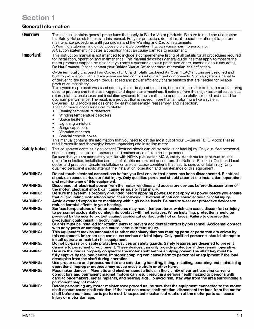
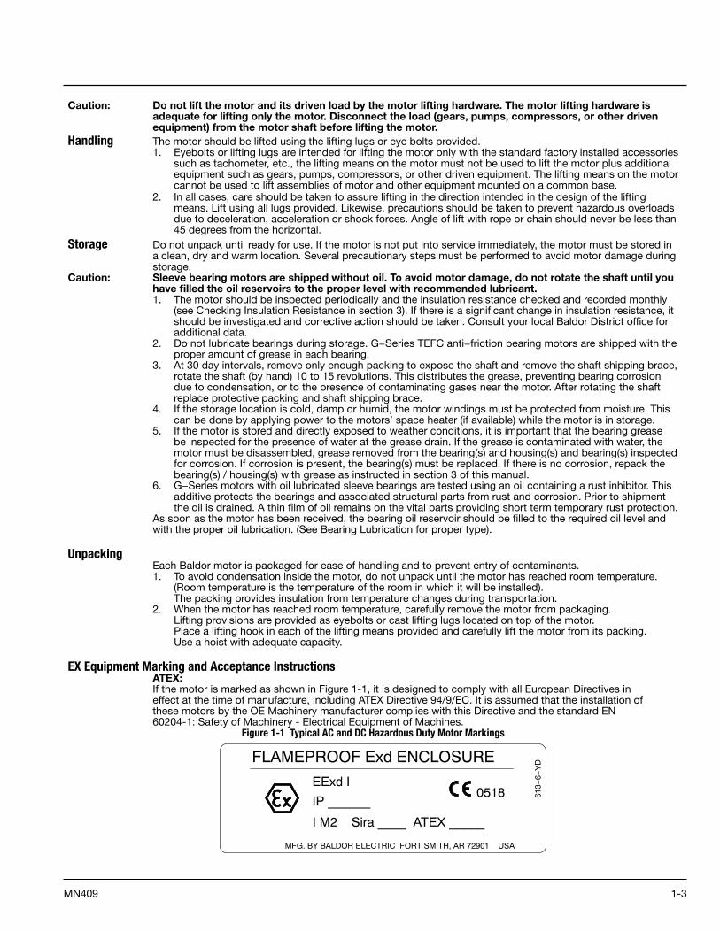
EX Equipment Marking and Acceptance InstructionsATEX:If the motor is marked as shown in Figure 1-1, it is designed to comply with all European Directives ineffect at the time of manufacture, including ATEX Directive 94/9/EC. It is assumed that the installation ofthese motors by the OE Machinery manufacturer complies with this Directive and the standard EN60204-1: Safety of Machinery - Electrical Equipment of Machines.
Figure 1-1 Typical AC and DC Hazardous Duty Motor Markings
MFG. BY BALDOR ELECTRIC FORT SMITH, AR 72901 USA
EExd I
IP ______
FLAMEPROOF Exd ENCLOSURE
0518 613−
6−Y
D
I M2 Sira ____ ATEX _____
1-4 MN409
Anyrepairsbytheenduser,unlessexpresslyapprovedbyBaldor•Reliance,releasesBaldor•Reliancefrom responsibility to conformity. Authorized and qualified personnel only must perform repairs. Thesemotors are designed in accordance with appropriate governmental regulatory agencies. They meet thetechnical requirements of the appropriate agencies at completion of manufacturing and have been issuedapproval numbers and nameplates. Any changes to these motors, may void these approvals and renderthese motors non-conforming and dangerous for use.These motors are suitable for the ATEX Group and Category marked on the equipment nameplate.These motors are designed for normal mining applications and are in compliance with the above safetydirectives when operated within the parameters identified on the motor nameplate.Specific motor type, frame designation, model number, date code, electrical specifications, and serialnumber are marked on a separate nameplate.Special Conditions are indicated on the motor nameplate as a suffix “X” on the certificate number.Details of this condition can be found on the motor approval certificate.
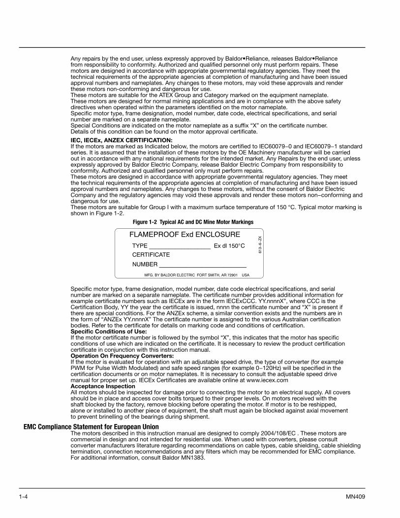
IEC, IECEx, ANZEX CERTIFICATION:If the motors are marked as Indicated below, the motors are certified to IEC60079−0 and IEC60079−1 standard series. It is assumed that the installation of these motors by the OE Machinery manufacturer will be carried out in accordance with any national requirements for the intended market. Any Repairs by the end user, unless expressly approved by Baldor Electric Company, release Baldor Electric Company from responsibility to conformity. Authorized and qualified personnel only must perform repairs.These motors are designed in accordance with appropriate governmental regulatory agencies. They meet the technical requirements of the appropriate agencies at completion of manufacturing and have been issued approval numbers and nameplates. Any changes to these motors, without the consent of Baldor Electric Company and the regulatory agencies may void these approvals and render these motors non−conforming and dangerous for use.These motors are suitable for Group I with a maximum surface temperature of 150 °C. Typical motor marking is shown in Figure 1-2.
Figure 1-2 Typical AC and DC Mine Motor Markings
Specific motor type, frame designation, model number, date code electrical specifications, and serialnumber are marked on a separate nameplate. The certificate number provides additional information forexample certificate numbers such as IECEx are in the form IECExCCC. YY.nnnnX”, where CCC is theCertification Body, YY the year the certificate is issued, nnnn the certificate number and “X” is present ifthere are special conditions. For the ANZEx scheme, a similar convention exists and the numbers are inthe form of “ANZEx YY.nnnnX” The certificate number is assigned to the various Australian certificationbodies. Refer to the certificate for details on marking code and conditions of certification.Specific Conditions of Use:If the motor certificate number is followed by the symbol “X”, this indicates that the motor has specificconditions of use which are indicated on the certificate. It is necessary to review the product certificationcertificate in conjunction with this instruction manual.Operation On Frequency Converters:If the motor is evaluated for operation with an adjustable speed drive, the type of converter (for examplePWM for Pulse Width Modulated) and safe speed ranges (for example 0−120Hz) will be specified in thecertification documents or on motor nameplates. It is necessary to consult the adjustable speed drivemanual for proper set up. IECEx Certificates are available online at www.iecex.comAcceptance InspectionAll motors should be inspected for damage prior to connecting the motor to an electrical supply. All coversshould be in place and access cover bolts torqued to their proper levels. On motors received with theshaft blocked by the factory, remove blocking before operating the motor. If motor is to be reshipped,alone or installed to another piece of equipment, the shaft must again be blocked against axial movementto prevent brinelling of the bearings during shipment.
EMC Compliance Statement for European UnionThe motors described in this instruction manual are designed to comply 2004/108/EC . These motors arecommercial in design and not intended for residential use. When used with converters, please consult converter manufacturers literature regarding recommendations on cable types, cable shielding, cable shielding termination, connection recommendations and any filters which may be recommended for EMC compliance. For additional information, consult Baldor MN1383.
MFG. BY BALDOR ELECTRIC FORT SMITH, AR 72901 USA
TYPE ___________________ Ex dl 150°C
CERTIFICATE
FLAMEPROOF Exd ENCLOSURE
613−
6−Z
XNUMBER ___________________________
2-1MN409
Section 2Installation & Operation
Overview Before installing the motor, be sure you read Section 1 and become familiar with the Warnings and Cautions to prevent damage to the motor and prevent injury to personnel. This is extremely important for a good installation and to ensure trouble free operation. Installation should conform to the National Electrical Code as well as local codes and practices. When other devices are coupled to the motor shaft, be sure to install protective devices to prevent future accidents. Some protective devices include, coupling, belt guard, chain guard, shaft covers etc. These protect against accidental contact with moving parts. Machinery that is accessible to personnel should provide further protection in the form of guard rails, screening, warning signs etc.1. If the motor has been in storage for an extended period or had been subjected to adverse moisture
conditions, check the insulation resistance of the stator winding (see Checking Insulation Resistance in section 3).
2. Examine the motor nameplate data to make sure it agrees with the power circuit to which it will be connected. The motor is guaranteed to operate successfully at line frequency not more than 5%, and line voltage not more than 10%, above or below the nameplate ratings, or a combined variation of voltage and frequency of not more than 10% above or below nameplate ratings. Efficiency, power factor and current may vary from nameplate data.
3. Check to make sure that direction of motor rotation is corrected for the intended application.Location
It is important that motors be installed in locations that are compatible with motor enclosure and ambient conditions. Improper selection of the motor enclosure and ambient conditions can lead to reduced operating life of the motor. The motor must be located in an environment that satisfies local codes and National Board of Fire and Underwriter’s regulations.The following additional considerations should also govern its location.On Totally Enclosed Fan Cooled (TEFC) motors the installation should be in a location that provides adequate space for air circulation of the external cooling fan. Exposure to high ambient temperatures, humidity and atmospheric contamination should be avoided. Acids, alkalis and gases also have detrimental effects on electrical machinery. The location of installation should be accessible for routine maintenance and inspection.If the room is not large enough to have natural ventilation, some external source of forced and filtered air will be necessary. The room should be such that the heat developed during operation can escape and will not be recirculated over the equipment.Permanent handling equipment to facilitate major service and repair without complete disassembly of the individual units should be considered.If the motor must be moved or additional handling or shipment of motor be required, be certain to block the shaft as it was blocked for shipment by the factory. Blocking the shaft, limits the rotor movement both axially and radially which prevents damage to the bearings.
Foundation The dimensions for mounting are shown on the outline drawing supplied with the motor software and should be referred to prior to planning of the foundation.The foundation should consist preferably of solid concrete walls or piers and should be carried down far enough to rest on a solid sub−base. This base should be sufficient stiffness to prevent vibration and to insure long, trouble free operation. If necessary, a consulting engineer, who is familiar with foundation design, should design and supervise its construction.If the foundation is to be steel girders instead of concrete, the girders should be well braced and supported by adequate columns to prevent vibration due to resonance. The natural frequencies of the motor and supporting structure must be at least 20% away from the speed of rotation and twice the speed of rotation and multiples of the power line frequency.The size of the foundation is determined by the weight, size and speed of the equipment and by the type and condition of the underlying soil. The width and length of the foundation are usually made to extend at least 6 inches (150mm) beyond the equipment on all sides of the base. Increased width and weight are necessary for operation at higher speeds and for foundations that project above the floor level to give stability against rocking and resonant vibration.Large motors are not rigid or self−supporting, and should be uniformly supported. Therefore, when set on the foundation or base, adequate support should be provided by leveling plates and shims between the frame and the foundation, at points of loading; Le., under the frame feet, and intersection points of the beams as well as under long, unsupported sections of the base. The number of shims should be kept to a minimum. A few thick ones are preferred over many thin ones.Space should be allowed between the base and foundation for grouting. The concrete surface should be roughed to provide a good bonding surface.
2-2 MN409
Pre−Installation Checks The assurance of successful start−up depends upon the use of good handling, inspection, and installation practices.
Caution: Sleeve bearing motors are shipped without oil. To avoid motor damage, do not rotate the shaft until you have filled the oil reservoirs to the proper level with recommended lubricant.Sleeve bearing motors are shipped without oil. Fill the oil reservoirs to the proper level before rotating the shaft. Failure to observe this precaution could result in damage to or destruction of the equipment.Before shipment, every motor is given a running test to check operation. Although complete factory tests have been made, motors should be checked for any change resulting from improper handling during shipment, storage, installation or by an unsatisfactory foundation. Failure to check or do the necessary work as mentioned above, could cause misalignment resulting in vibration and premature bearing failure.Before the motor is checked for alignment, remove all shipping blocks and supports installed at the factory. The shaft should turn over freely. The degree of accuracy required in the alignment depends on the rated speed of the machine. The greater the speed, the greater the care and accuracy necessary in the alignment.The motor must be level to maintain the proper oil level. Check the driven equipment to make sure that the motor will be coupled to a level shaft. If necessary, level it up before coupling.
Grouting A good quality commercial non−shrinking type of grouting compound should be used between foundation concrete and all sole poles.
Doweling & Bolting After proper alignment is verified, dowel pins should be inserted through the motor feet into the foundation. This will maintain the correct motor position should motor removal be required. (Baldor motors are designed for doweling.)1. Drill dowel holes in diagonally opposite motor feet in the locations provided.2. Drill corresponding holes in the foundation.3. Ream all holes.4. Install proper fitting dowels.5. Mounting bolts must be carefully tightened to prevent changes in alignment. Use a flat washer and lock
washer under each nut or bolt head to hold the motor feet secure. Flanged nuts or bolts may be used as an alternative to washers.
Caution: Do not use the coupling to compensate for poor alignment. This can result in vibration, noise, coupling wear, overloaded bearings and early failure.
Coupling1. In preparation for making the coupling alignment, wash off the rust−protective compound on the motor shaft
and factory−installed couplings with solvent.2. Fill oil sumps with the recommended oil to the proper level before mounting the coupling.3. The couplings should be heated for proper mounting. Do not press or drive couplings onto the shaft.
Coupling AlignmentThere are a number of different procedures in alignment of the motor to the driven equipment. The end result depends upon the accuracy of the parts in roundness, flatness, runout of the reference surfaces, rigidity of the mounting and the skill of the set−up−person. The motor base surfaces must be flat and parallel to the shafts. Make allowance for inserting shims under the motor to make the elevation adjustment. The size of the shims’ should be the full length of the motor foot pad, they should be flat, and free of any burrs. Insert the shims carefully to maintain the foot plane and to avoid bending or twisting the motor frame. For a poor mounting surface, it may be necessary to machine a shim to compensate for the slope or surface irregularity. To minimize soft stacking and sponginess associated with excessive layers, use the thickest shim stock combination with the fewest shims.Refer to accepted procedures for coupling alignment such as double−dial indicator or laser alignment.Coupling alignment shall be within the following limits:• MAXIMUM PERMISSIBLE ANGULAR MISALIGNMENT = .001 inch per inch of coupling hub diameter.• MAXIMUM PERMISSIBLE PARALLEL MISALIGNMENT = .002 inch TIR (Total Indicated Runout).
Lubrication The lubrication system should be checked in preparation for rotating the shaft during the alignment operation.Anti−Friction Bearings (Grease Lubricated)
Bearing chambers are packed with grease during assembly, and do not normally need additional grease at time of installation, unless the unit has been in storage and installation for 6 months or longer. Lubricant must be added per Section 4, Maintenance.
Sleeve Bearing (Oil Lubricated)If the motor has been in storage for six months or more, the bearing oil must be changed per Section 4 for Standard Conditions.Sleeve bearing motors are shipped from factory without oil. Fill oil sumps to proper level before rotating the shaft. Failure to observe this precaution could result in damage to or destruction of the equipment. To fill sleeve−bearing motor oil reservoirs on motors not equipped with constant level oilers, be sure that the drain plugs are in place and secure. Fill through filler cap until oil level shows in the oil gauge. Fill oil to midway point of the gauge. For motors with constant level oilers, refer to the instructions under the Accessories section.On motors equipped with circulating oil lube system and adjustable needle valve, valve must be adjusted or flooding of oil sump may occur. Disconnect valve and adjust to flow rate, pressure, and temperature as defined on dimension sheet or nameplate. If dimension sheet is not available contact your Baldor District Office.
2-3MN409
Electrical ConnectionWARNING: Be sure the system is properly grounded before applying power. Do not apply AC power before you ensure
that all grounding instructions have been followed. Electrical shock can cause serious or fatal injury. National Electrical Code and Local codes must be carefully followed.A main terminal box may be provided for power lines to the stator. Other terminal boxes for all other electrical connections may be provided. Motor and control wiring, overload protection, disconnects, accessories and grounding should conform to the National Electrical Code and local codes and practices. AC Power Connect the motor leads as shown on the connection diagram located on the name plate or inside the cover on the conduit box. Be sure the following guidelines are met:1. AC power is within ±10% of rated voltage with rated frequency. (See motor name plate for ratings).OR2. AC power is within ±5% of rated frequency with rated voltage.OR3. A combined variation in voltage and frequency of ±10% (sum of absolute values) of rated values, provided
the frequency variation does not exceed ±5% of rated frequency.
Grounding Failure to properly ground the motor may cause electrical shock hazard to personnel.All large motors should be grounded with the grounding conductor equipped with a brazed copperterminal, or with a suitable solderless terminal fastened to the motor. Soldered terminals should not beused. A washer should be used between bolt head and terminal lug. The other end should be fastenedwith suitable clamps or terminals to rigid metallic conduit or to the nearest available ground. Groundingconductor size should be in accordance with the following National Electrical Code Table 250−95.Installation restrictions are listed in Section 250−92.
WARNING: This equipment is at line voltage when AC power is connected. Disconnect and lockout all ungrounded conductors of the ac power line before proceeding. Failure to observe these precautions could result in severe bodily injury or loss of life.
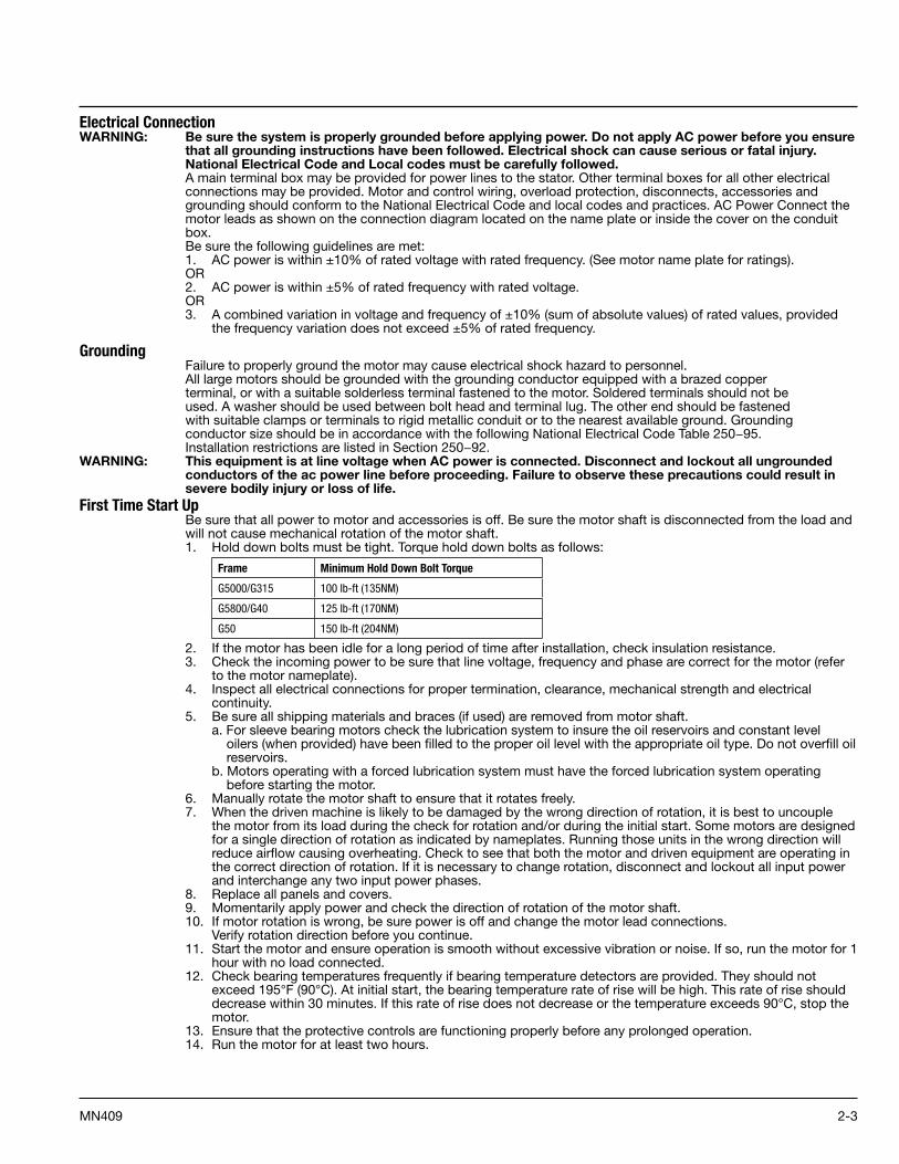
First Time Start Up Be sure that all power to motor and accessories is off. Be sure the motor shaft is disconnected from the load and will not cause mechanical rotation of the motor shaft.1. Hold down bolts must be tight. Torque hold down bolts as follows:
Frame Minimum Hold Down Bolt Torque
G5000/G315 100 lb-ft (135NM)
G5800/G40 125 lb-ft (170NM)
G50 150 lb-ft (204NM)
2. If the motor has been idle for a long period of time after installation, check insulation resistance.3. Check the incoming power to be sure that line voltage, frequency and phase are correct for the motor (refer
to the motor nameplate).4. Inspect all electrical connections for proper termination, clearance, mechanical strength and electrical
continuity.5. Be sure all shipping materials and braces (if used) are removed from motor shaft. a. For sleeve bearing motors check the lubrication system to insure the oil reservoirs and constant level
oilers (when provided) have been filled to the proper oil level with the appropriate oil type. Do not overfill oil reservoirs.
b. Motors operating with a forced lubrication system must have the forced lubrication system operating before starting the motor.
6. Manually rotate the motor shaft to ensure that it rotates freely.7. When the driven machine is likely to be damaged by the wrong direction of rotation, it is best to uncouple
the motor from its load during the check for rotation and/or during the initial start. Some motors are designed for a single direction of rotation as indicated by nameplates. Running those units in the wrong direction will reduce airflow causing overheating. Check to see that both the motor and driven equipment are operating in the correct direction of rotation. If it is necessary to change rotation, disconnect and lockout all input power and interchange any two input power phases.
8. Replace all panels and covers.9. Momentarily apply power and check the direction of rotation of the motor shaft.10. If motor rotation is wrong, be sure power is off and change the motor lead connections.
Verify rotation direction before you continue.11. Start the motor and ensure operation is smooth without excessive vibration or noise. If so, run the motor for 1
hour with no load connected.12. Check bearing temperatures frequently if bearing temperature detectors are provided. They should not
exceed 195°F (90°C). At initial start, the bearing temperature rate of rise will be high. This rate of rise should decrease within 30 minutes. If this rate of rise does not decrease or the temperature exceeds 90°C, stop the motor.
13. Ensure that the protective controls are functioning properly before any prolonged operation.14. Run the motor for at least two hours.
2-4 MN409
Coupled Start Up This procedure assumes a coupled start up. Also, that the first time start up procedure was successful. Read and
fully understand each of the steps in the following procedure before attempting to start the motor.1. Disconnect and lockout the power source. Ensure no power is applied to the motor.2. After a successful uncoupled start, assemble the coupling and lubricate with the manufacturer’s
recommended lubricant. Check to see that the coupling is not binding. 3. After the coupling has been assembled and lubricated, repeat steps 11 through 14 under First Time Start Up.
Check to see that the driven equipment is not transmitting vibration back to the motor through the coupling or the base.
4. Check to see that coupling guards and other protective enclosures are not blocking the ventilating air over the motor and exhaust openings.
5. When alignment is correct and motor is properly lubricated, prepare for no load run uncoupled start−up. The coupling should be uncoupled and a solo plate should be installed if required.
6. Inspect the motor carefully. Make the initial start by following the regular sequence of starting operations in the control instructions.
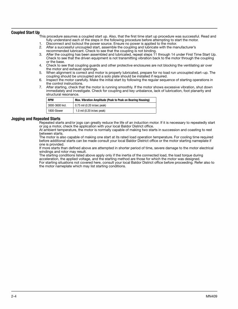
7. After starting, check that the motor is running smoothly. If the motor shows excessive vibration, shut down immediately and investigate. Check for coupling and key unbalance, lack of lubrication, foot planarity and structural resonance.
RPM Max. Vibration Amplitude (Peak to Peak on Bearing Housing)
3000-3600 Incl. 0.75 mil (0.20 in/sec peak)
1800-Slower 1.0 mil (0.20 in/sec peak)
Jogging and Repeated StartsRepeated starts and/or jogs can greatly reduce the life of an induction motor. If it is necessary to repeatedly start or jog a motor, check the application with your local Baldor District office.At ambient temperature, the motor is normally capable of making two starts in succession and coasting to rest between starts.The motor is also capable of making one start at its rated load operation temperature. For cooling time required before additional starts can be made consult your local Baldor District office or the motor starting nameplate if one is provided.If more starts than defined above are attempted in shorter period of time, severe damage to the motor electrical windings and rotor may result.The starting conditions listed above apply only if the inertia of the connected load, the load torque during acceleration, the applied voltage, and the starting method are those for which the motor was designed.For starting situations not covered here, consult your local Baldor District office before proceeding. Refer also to the motor nameplate which may list starting conditions.
3-1MN409
Section 3Maintenance & Troubleshooting
G−Series AC motors when properly applied, require minimal routine maintenance. Since clearances andfits are precisely machine, no periodic mechanical adjustments are required. Like any precision machine,periodic inspection and simple routine maintenance will prolong your motor’s life and help spot potentiallydamaging conditions. The minimal time spent performing the simple procedures below cannot begin tocompare with the cost of lost productivity and time consuming major repairs incurred through neglect orroutine inspection and maintenance.In addition, the following should always be observed.• Provide adequate ventilation. • Keep air and exhaust openings clean and free of obstructions.• Avoid sharp blows and excessive axial thrust loads on the output shaft.• Maintain proper lubricant level (check weekly on oil lubricated units).
Caution: Do not use solvents containing trichloroethane to clean interior or exterior of motor. Damage may occur to paint and insulation systems.
Periodic Inspection Inspections are important to the proper operation and maintenance of a motor, should occurevery 3 months (or 500 operating hours whichever comes first).1. Listen for any abnormal noises and check cause immediately.2. Check voltage and frequency variations. Unbalanced voltage or single phase operation of poly phase motors
will cause excessive heating and ultimately failure. Only a slight unbalance of voltage applied to a poly phase motor will cause large unbalance currents and result in overheating.
3. Check power supply total harmonic distortion to avoid overheating.4. Periodic checks of phase, voltage, frequency, and power consumption of an operating motor are
recommended.5. Check for excessive vibration.6. Check all air passages and ensure that they are not blocked or clogged.7. Check to see that all covers are in place and secure.8. Disconnect and lockout the power source. Ensure no power is applied to the motor.9. Provide adequate ventilation. If the motor is not properly ventilated, overheating can occur and cause early
motor failure.10. Keep air and exhaust openings clean and free of obstructions.11. Avoid sharp blows and excessive axial thrust loads on the output shaft.12. Maintain proper lubricant level (check weekly on oil lubricated units).13. Check all electrical connectors to be sure that they are tight.14. Check for proper lubrication. For sleeve bearing motors check oil level. The oil level must be at the midpoint
of sight gauge when the motor is at rest and in operation.15. Check bearing temperature rise.16. When provided, check that constant level oilers have oil in them.
Check that cap on oiler is screwed on tightly. Make sure the oil is clean.These checks can also provide an excellent indication of the load from the driven equipment.Comparisons of this data with previous no load and full load power demands will give an indication of the performance of the driven machine.
Bearing LubricationDepending on the application and rating, the motor is equipped with either anti−friction or sleeve typebearings. When properly cared for (ie., inspection and lubrication) bearings will provide years ofuninterrupted service. Use one of the following lubrication procedures, depending on the type of bearingswith which your motor is equipped.
Anti−Friction Bearing (Grease Lubricated)G−Series AC motors are designed with the Baldor direct grease system which routes new grease directly into the bearing.The relubrication periods shown in Table 3-2 are offered as a guide for varying service conditions, speeds, bearing types and operating hours.Cleanliness is important in lubrication. Any grease used to lubricate anti−friction bearings should be fresh and free from contamination. Similarly, care should be taken to properly clean and grease inlet areas of the motor to prevent grease contamination.Mixing of lubricants must not be done. Lubricants from different manufacturers and of different compositions may not be compatible, resulting in inadequate lubrication and bearing failure. If a lubricant other than that listed on the motor nameplate and/or this instruction manual is desired to be used, first consult your local Baldor District office for approval and instructions. Do not use automotive greases, greases with EP additives or greases other than those specifically listed on the motor lubrication nameplate and this instruction manual. Failure to follow these instructions may result in lubrication breakdown and bearing failure.Recommended LubricantRefer to motor nameplate. Use only clean, fresh grease from clean containers. A high grade ball or roller bearing polyurea base hydrocarbon grease should be used.Recommended grease for standard service conditions is Polyrex EM (Exxon Mobil).Do not mix greases unless compatibility has been checked and verified.Contact your Baldor District Office if you have compatibility questions.Equivalent and compatible greases include:Texaco Polystar, Rykon Premium #2, Pennzoil Pen 2 Lube and Chevron SRI.
3-2 MN409
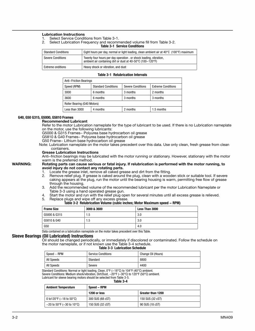
Lubrication Instructions1. Select Service Conditions from Table 3-1.2. Select Lubrication Frequency and recommended volume fill from Table 3-2.
Table 3-1 Service Conditions
Standard Conditions Eight hours per day, normal or light loading, clean ambient air at 40°C (100°F) maximum
Severe Conditions Twenty four hours per day operation . or shock loading, vibration, ambient air containing dirt or dust at 40 -50°C (100−120°F)
Extreme onditions Heavy shock or vibration, and dust
Table 3-1 Relubrication Intervals
Anti−Friction Bearings
Speed (RPM) Standard Conditions Severe Conditions Extreme Conditions
3000 6 months 3 months 2 months
3600 6 months 3 months 3 months
Roller Bearing (G40 Motors)
Less than 3000 4 months 2 months 1.5 months
G40, G50 G315, G5000, G5810 FramesRecommended LubricantRefer to the motor Lubrication nameplate for the type of lubricant to be used. If there is no Lubrication nameplate on the motor, use the following lubricants:G5000 & G315 Frames− Polyurea base hydrocarbon oil greaseG5810 & G40 Frames− Polyurea base hydrocarbon oil greaseG50 Frame− Lithium base hydrocarbon oil grease
Note: Lubrication nameplate on the motor takes precedent over this data. Use only clean, fresh grease from clean containers.
Grease Lubrication InstructionsAnti−friction bearings may be lubricated with the motor running or stationary. However, stationary with the motor warm is the preferred method.
WARNING: Rotating parts can cause serious or fatal injury. If relubrication is performed with the motor running, to avoid injury do not contact any rotating parts.1. Locate the grease inlet, remove all caked grease and dirt from the fitting.2. Remove relief plug. If grease is caked around the plug, clean with a wooden stick or suitable tool. If severe
caking appears at the plug, run the motor until the bearing housing is warm, permitting free flow of grease through the housing.
3. Add the recommended volume of the recommended lubricant per the motor Lubrication Nameplate or Table 3-3 using a hand operated grease gun.
4. Start the motor and run with the relief plug open for several minutes until all excess grease is relieved.5. Replace plugs and wipe off any excess grease.
Table 3-2 Relubrication Volume (cubic inches; Motor Maximum speed − RPM)
Frame Size 3000 & 3600 Less Than 3000
G5000 & G315 1.5 3.0
G5810 & G40 1.5 3.0
G50 4.0
Data contained on a lubrication nameplate on the motor takes precedent over this Table.
Sleeve Bearings (Oil Lubricated) InstructionsOil should be changed periodically, or immediately if discolored or contaminated. Follow the schedule onthe motor nameplate, or if not known use the Table 3-4 schedule.
Table 3-3 Lubrication Schedule
Speed − RPM Service Conditions Change Oil (Hours)
All Speeds Standard 8800
All Speeds Severe 4400
Standard Conditions: Normal or light loading, Clean, 0°F (−18°C) to 104°F (40°C) ambient. Severe Conditions: Medium shock/vibration, Dirt/Dust, −20°F (−30°C) to 120°F (50°C) ambient. Lubricant for sleeve bearing motors should be selected from Table 3-5.
Table 3-4
Ambient Temperature Speed − RPM
1200 or less Greater than 1200
0 to120°F (−18 to 50°C) 300 SUS (68 cST) 150 SUS (32 cST)
−20 to 50°F (−30 to 10°C) 150 SUS (32 cST) 90 SUS (18 cST)
3-3MN409
• For higher temperature, oil coolers should be used.• For lower temperatures, heaters should be used to assure adequate starting temperatures.Viscosity in SUS (centistokes) at 100°F (37.8°C).Pour point: Below minimum starting temperature.Quality: Use a good grade of turbine type oil, with rust, foam, and oxidation inhibitors.Avoid automotive oils or additives unless specifically recommended by the oil manufacturer.
Oil Change Procedure1. Disconnect and lockout the power source. Ensure no power is applied to the motor.2. Remove the drain plug, located at the bottom of the bearing housing.
For the non−drive end, the oil drain pipe is labeled on the fan cover.3. If the oil appears to be contaminated, the housing can be flushed out by filling with fresh oil and draining
again until oil is clean.4. Replace plug and fill at oil fill to the sight gauge mid point.5. Tighten fill cap and plugs, fill constant level oiler if provided.6. Start unit and observe to be assured of no oil leakage and level does not drop.
G50 Sleeve Bearing & Cartridge Removal Instructions1. Disconnect and lockout the power source. Ensure no power is applied to the motor.2. Remove the fan cover/air scoop and accessories (forced lubrication plumbing) that are assembled to the end
shield and bearing housing.3. Loosen bolts and remove protective cover bolted to flange of the end shield.4. The bearing housing must be disassembled from the end shield before removing the end shield from the
frame.5. Remove drain plug at bottom of bearing housing and drain oil from the reservoir.6. Loosen and remove the bolts at the split line of the bearing housing.7. If the motor has insulated bearings and meets API−541 , a machined seal will be assembled outboard of the
bearing housing. The seal must be dissembled from the bearing housing before removing the top half of the bearing housing. The seal is insulated from the bearing housing with a non−split gasket. The bearing housing top half can not be removed unless the seal and gasket are disassembled from the bearing housing.
8. Use the lifting eye bolts, lift the bearing housing top half straight up and pull forward away from the bearing area to clear the end shield. Insure that the bearing and seals are cleared before moving the bearing housing top half forward.
9. Lift the upper half of the bearing liner and remove from bearing housing.10. Loosen and remove the bolts at the split line of the oil ring.11. Remove oil ring.12. Disassemble the garter springs that encircle the labyrinth seals (inboard and outboard).13. Lift and remove the upper half of each seal. Rotate the lower half out of the seal carrier.
Note: The labyrinth seals must be assembled so that the locking tabs will be in the 9:00 position. The drain back holes in the seal face must face towards the oil sump and be located in the 6:00 position.
14. Disconnect and remove RTD’s from the lower half of the bearing liner.15. Use hoist, jack or a non−metallic sling around the shaft to lift the shaft off the lower half of the bearing liner.
Roll the lower half of the bearing liner out of the bearing housing.16. Loosen and remove the bolts securing the bottom half of the bearing housing to the end shield. Use eye
bolts and hoist to remove the bottom half of housing. Shims for axial location of the shaft are located between the lower bearing housing and end cap machined fits.
Note their location for reassembly.17. The inboard machined seal, outboard seal carrier, and bolt on baffle are still attached to the bearing housing.
These parts can be removed by loosening all bolts and disassembling.18. For reassembly perform the above listed steps in reverse order. Assemble both the bottom and top half of the
seals. Press up on the bottom half of the outboard seal and baffle so that there is no clearance between the seal and shaft at the bottom. Make sure that the clearance from side to side is symmetric.
19. All machined split line surfaces of the bearing housing and seals must be coated with a sealing compound (Curil T or Permatex #3). Also apply seal compound to the flange of the machined seals and seal carrier.
G50 Sleeve Bearing Replacement1. The sleeve bearing may be replaced without disturbing the setup and uncoupling from the driven equipment.
Remove the top and bottom bearing liners at stated in “G50 Sleeve Bearing & Cartridge Removal Instructions”.
2. Make sure that the shaft bearing shoulders and journal are free of nicks and burrs before replacing bearing. Dress shaft with emery cloth or stone as necessary. Clean the shaft and oil sump thoroughly.
3. Apply a coating of oil to the bearing journal.4. Inspect the replacement bearing for nicks and damage. The bearing may be packed in a waxy rust inhibiting
compound. Remove all wax from bearing surfaces using solvent. Dry bearing before assembling in housing. The bearings are spherical self seating. Apply a coat of oil to the outside diameter of the bearing liner and also to the bearing housing bore. Do not scrape the bearing Babbitt surface for seating.
5. Reassemble the motor. Apply sealant to the split line of bearing housing seals.6. Fill oil reservoir so that oil is at the midway point in the sight gauge.7. Slowly rotate the shaft to insure the bearings and seals are seated properly.
3-4 MN409
G5000, G315, G5810 and G40 Sleeve Bearing & Cartridge Removal1. Disconnect and lockout the power source. Ensure no power is applied to the motor.2. Remove the fan cover/air scoop and accessories (forced lubrication plumbing) that are assembled to the end
shield and bearing housing. Loosen bolts and remove protective cover bolted to flange of the end shield.3. The bearing housing must be disassembled from the end shield before removing the end shield from the
frame.4. Remove drain plug at bottom of bearing housing and drain oil from the reservoir. 5. Loosen and remove the bolts at the split line of the bearing housing. Remove top half of bearing housing.6. Pry slots are provided on the outboard bearing face to facilitate removing top of the bearing housing.7. Using hand pressure, separate the bearing halves. (Bearings halves are doweled together).
Note: Some models are equipped with socket head screws in addition to the dowels. These screws must be removed before attempting to remove bearing top half.
8. Remove top half of bearing and bearing anti−rotation keying devices from bearing housing.9. Remove Bearing RTD’s if supplied.10. Using a rope or sling (Nonmetal) around the shaft, raise it just high enough to be able to spin out the bottom
half of the bearing.Note: Shims used for axial float are located on the outboard end of the bearing in the housing. Remove and note
the quantity used at each end.11. Remove the bottom half of bearing and gently lower shaft.12. To remove bottom half of bearing cartridge, use eye bolts to support weight of cartridge and then remove
mounting bolts.13. For reassembly perform the above listed steps in reverse order.14. All machined split line surfaces of the bearing housing and seals must be coated with a sealing compound
(Curil T or Permatex #3). G5000, G315, G5810 and G40 Sleeve Bearing Replacement
1. Remove bearing as listed in section “G5000, G315, G5810 and G40 Sleeve Bearing and Cartridge Removal”.2. Check to see that bearing journal and shoulders are free of nicks and burrs; dress with rubber stone or
replace as necessary.3. Using a clean lint free cloth, wipe bearing journal and bearing clean and dry. Shaft and bearing bore must be
free of oil.4. Raise the shaft as required to reassemble bearing. Install the bottom half of the bearing.5. Gently lower the shaft until it is in its final position.6. Assemble top half of bearing.7. Reassemble parts in reverse order of removal. Make sure dowel pins are engaged in top and bottom halves
of housing.8. By hand (or suitable wrench) slowly rotate the shaft 2 turns in each direction.9. Remove bearing as listed in section “G5000, G315, G5810 and G40 Sleeve Bearing and Cartridge Removal”.
Inspect bore of both bearing halves for burnished (shiny) areas. A correct burnish pattern is: Top half of bearing − no burnished areas Bottom half of bearing − burnish area symmetric about the 6:00 position, one to two inches wide, covering approximately 70% of the axial length of the bearing bore.
10. If the correct burnish pattern is not found perform the following: a. Using the proper bearing scraping tools and/or a nonmetallic fiber pad, remove the highly
burnished areas. b. Clean the bearing and shaft journal with a film free solvent such as denatured alcohol.11. Repeat steps 3−10 until the correct burnish pattern is obtained.12. Wipe bearing and journal and pour fresh clean oil on bearing journal and over bearing. Be sure to cover
both inside and outside diameters with oil. Install bottom half of bearing. Use caution to prevent damage to bearing and to prevent dirt from contaminating bearing surface.
13. Replace anti−rotation keys. Tabs to prevent axial bearing movement should be install pointing toward the bearing.
14. Assemble top half of bearing.15. Reassemble parts in reverse order of removal. Make sure dowel pins are engaged in top and bottom halves
of housing. Apply a sealing compound (Curil T or Permatex #3) to faces of lower bearing housing.
Sleeve/Anti−Friction Bearing Bracket Removal1. For anti−friction bearing motors the inner cap bolts must be removed before removing the end shield.2. For sleeve bearing motors the bearing cartridge must be removed before disassembly of the end shield. (See
G5000, G315, G5810 and G40 Sleeve Bearing & Cartridge Removal).3. Remove all bolts that secure the end shield to the frame.4. Using a hoist, support the bracket.5. To remove the G50 bracket from rabbet fit, jacking holes have been provided next to the four bracket bolts
located at 45°. Tighten jack bolts evenly to avoid axial misalignment of the end shield. To remove the G5000, G315, G5810 and G40 brackets from the rabbet fit, pry bar slots have been provided on the lugs.
Anti−Friction Bearing Removal/Replacement1. Remove the end shield (see Sleeve/Anti−Friction Bearing Bracket Removal).2. The bearing can now be removed by using a conventional bearing puller with the puller arms located behind
the bearing race. Protect the shaft center by using a spacer block of bass or some other soft material between the shaft and bearing puller.
3. Clean and inspect all parts. Remove all old grease.
3-5MN409
4. All shaft bearing shoulders and journals should be free of nicks before replacing bearing. Dress shaft with emery cloth or stone as necessary.
5. Heat bearing to 250°F (120°C) for at least 30 minutes.6. Place bearing onto shaft. Make certain that the bearing is contacting the locating shoulder on shaft.
Do not use impact force on bearing.7. Let the bearing cool. Grease the outboard side cavity of the bearing 100%. Grease inner caps and bracket
bearing housing to 60% full.8. Assemble end shield in reverse order. (See Sleeve/Anti−Friction Bearing Bracket Removal).
Rotor And Stator RemovalConsult your local Baldor District office for proper removal procedures.
Winding MaintenanceWARNING: Solvents can be toxic and/or flammable. Follow manufacturer’s safety procedures and directions. Failure
to observe this precaution could result in bodily injury.Caution: Do not use solvents containing trichloroethane to clean interior or exterior of motor. Damage may occur to
paint and insulation systems.Disconnect and lockout the power source. Ensure no power is applied to the motor. To inspect the ends and outside surface of the windings, remove the brackets from the motor. Inspection of these portions of the windings will provide a good indication of their general condition. To thoroughly inspect and clean the windings it may be necessary to remove the rotor.There are numerous methods for cleanings windings. The following methods are most commonly used, in order of preference.
Note: Before cleaning the windings check for loose blockings, evidence of damage to insulation, distortion or movement of coils, etc. If any of these conditions exist, contact your local Baldor District office for recommendations.
Dry WipingThis method is satisfactory when the surfaces to be cleaned are accessible and when only dry dirt is to be removed. Use a clean dry, lint free cloth. The lint will adhere to the insulation and increase dirt collection. Lint is particularly objectionable on high voltage insulation systems as it tends to concentrate corona discharge.
Brushing and Suction CleaningRemove the dry dust and dirt by brushing with a bristle brush, followed by a vacuum suction cleaning.DO NOT USE WIRE BRUSHES.
BlowingWARNING: Use of an air jet may cause flying debris and generate particulate matter. Wear suitable skin, eye and
respiratory protection. Failure to observe this precaution may result in bodily injury.Caution: To avoid damage to the windings do not use air pressures greater than 30 psi (200 kPa). Avoid directing the
air in such a way that the dirt will be blown into inner crevices.Dry Dirt and dust can be removed from inaccessible crevices by using a jet of low pressure, oil free compressed dry air.
Solvent CleaningCaution: Do not use solvents containing trichloroethane to clean interior or exterior of motor. Damage may occur to
paint and insulation systems.
Cleaning With Water And DetergentWindings can be cleaned by hose washing or by pressure spray from a low pressure steam generator orshop steam line.
Caution: To avoid damage to the windings do not use air pressures greater than 30 psi (200 kPa). Avoid directing the air in such a way that the dirt will be blown into inner crevices.Oil, grease, tar and wax can be removed by adding a Nonconductive Detergent to the wash water.After washing, it is necessary to dry the windings in an oven. (See “Checking Insulation Resistance”)
Reconditioning (Re−impregnating) WindingsIf after cleaning with solvent or water and detergent, the insulation shows signs of dryness, it may be necessary to re−impregnate the windings. Consult your local Baldor District office.
Checking Insulation ResistanceIf the motor has been in storage for an extensive period or has been subjected to adverse moisture conditions, check the insulation resistance of the stator winding with an insulation resistance meter. The minimum insulation resistance (RM) can be determined from the following formula: RM = KV + 1 Where RM = Minimum insulation resistance in mega ohms at 40°C of the entire machine winding. KV = Rating machine potential, in kilovolts.For machines in good condition, insulation and resistance readings of 10 to 100 times RM are common.If the insulation resistance is lower than that calculated from the formula, the windings should be dried out as follows:Bake in an oven (preferably a circulating air oven) at a temperature not over 90°C until insulation resistance remains constant.
3-6 MN409
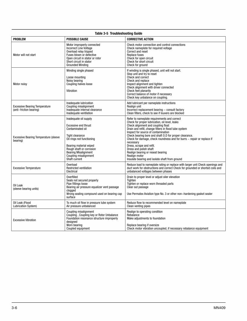
Table 3-5 Troubleshooting Guide
PROBLEM POSSIBLE CAUSE CORRECTIVE ACTION
Motor will not start
Motor improperly connected Incorrect Line Voltage Overload relay tripped Fuses blown or defective Open circuit in stator or rotor Short circuit in stator Grounded Winding
Check motor connection and control connections Check nameplate for required voltage Correct and reset Replace fuses Check for open circuit Check for short circuit Check for ground
Motor noisy
Winding single phased
Loose mounting Noisy bearing Coupling halves loose
Vibration
If winding is single phased, unit will not start. Stop unit and try to reset Check and correct Check and replace Inspect alignment and tighten Check alignment with driver connected Check feet planarity Correct balance of motor if necessary Check key unbalance on coupling.
Excessive Bearing Temperature (anti−friction bearing)
Inadequate lubrication Coupling misalignment Inadequate internal clearance Inadequate ventilation
Add lubricant per nameplate instructions Realign unit Incorrect replacement bearing − consult factory Clean filters, check to see if louvers are blocked
Excessive Bearing Temperature (sleeve bearing)
Inadequate oil supply Excessive end thrust Contaminated oil
Tight clearance Oil rings not functioning
Bearing material wiped Rough shaft or corrosion Bearing Misalignment Coupling misalignment Shaft current
Refer to nameplate requirements and correct Check for proper lubrication, oil level, leaks Check alignment and coupling float Drain and refill, change filters in flood lube system Inspect for source of contamination Check bearing bore and shaft O.D for proper clearance. Check for damage, check roundness and for burrs − repair or replace if necessary Dress, scrape and refit. Dress and polish shaft Realign bearing or reseat bearing Realign motor Insulate bearing and isolate shaft from ground
Excessive TemperatureOverload Restricted ventilation Electrical
Reduce load to nameplate rating or replace with larger unit Check openings and duct work for obstructions and correct Check for grounded or shorted coils and unbalanced voltages between phases
Oil Leak (sleeve bearing units)
Overfilled Seals not secured properly Pipe fittings loose Bearing air pressure equalizer vent passage clogged Wrong sealing compound used on bearing cap surface
Drain to proper level or adjust oiler elevation Tighten Tighten or replace worn threaded parts Clear out passage
Use Permatex Aviation type No. 3 or other non−hardening gasket sealer
Oil Leak (Flood Lubrication System)
To much oil flow in pressure lube system Air pressure unbalanced
Reduce flow to recommended level on nameplate Clean venting pipes
Excessive Vibration
Coupling misalignment Coupling , Coupling key or Rotor Unbalance Foundation resonance structure improperly designed Worn bearing Coupled equipment
Realign to operating condition Rebalance Make adjustments to foundation
Replace bearing if oversize Check motor vibration uncoupled, if necessary rebalance equipment
4-1MN409
Section 4Optional Accessories
The owner is responsible for conformance to national electric code and all other applicable local codes and practices. Refer to Safety Notice in Section 1 of this manual.
Note: Motor is equipped with the following accessories only if ordered with the motor.
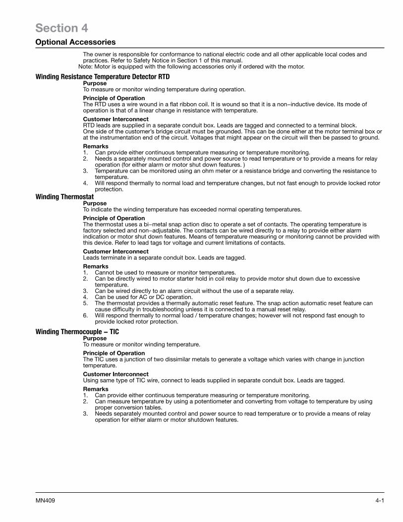
Winding Resistance Temperature Detector RTDPurposeTo measure or monitor winding temperature during operation.
Principle of OperationThe RTD uses a wire wound in a flat ribbon coil. It is wound so that it is a non−inductive device. Its mode of operation is that of a linear change in resistance with temperature.
Customer InterconnectRTD leads are supplied in a separate conduit box. Leads are tagged and connected to a terminal block.One side of the customer’s bridge circuit must be grounded. This can be done either at the motor terminal box or at the instrumentation end of the circuit. Voltages that might appear on the circuit will then be passed to ground.
Remarks1. Can provide either continuous temperature measuring or temperature monitoring.2. Needs a separately mounted control and power source to read temperature or to provide a means for relay
operation (for either alarm or motor shut down features. )3. Temperature can be monitored using an ohm meter or a resistance bridge and converting the resistance to
temperature.4. Will respond thermally to normal load and temperature changes, but not fast enough to provide locked rotor
protection.Winding Thermostat
PurposeTo indicate the winding temperature has exceeded normal operating temperatures.
Principle of OperationThe thermostat uses a bi−metal snap action disc to operate a set of contacts. The operating temperature is factory selected and non−adjustable. The contacts can be wired directly to a relay to provide either alarm indication or motor shut down features. Means of temperature measuring or monitoring cannot be provided with this device. Refer to lead tags tor voltage and current limitations of contacts.
Customer InterconnectLeads terminate in a separate conduit box. Leads are tagged.
Remarks1. Cannot be used to measure or monitor temperatures.2. Can be directly wired to motor starter hold in coil relay to provide motor shut down due to excessive
temperature.3. Can be wired directly to an alarm circuit without the use of a separate relay.4. Can be used for AC or DC operation.5. The thermostat provides a thermally automatic reset feature. The snap action automatic reset feature can
cause difficulty in troubleshooting unless it is connected to a manual reset relay.6. Will respond thermally to normal load / temperature changes; however will not respond fast enough to
provide locked rotor protection.
Winding Thermocouple − TICPurposeTo measure or monitor winding temperature.
Principle of OperationThe TIC uses a junction of two dissimilar metals to generate a voltage which varies with change in junction temperature.
Customer InterconnectUsing same type of TIC wire, connect to leads supplied in separate conduit box. Leads are tagged.
Remarks1. Can provide either continuous temperature measuring or temperature monitoring.2. Can measure temperature by using a potentiometer and converting from voltage to temperature by using
proper conversion tables.3. Needs separately mounted control and power source to read temperature or to provide a means of relay
operation for either alarm or motor shutdown features.
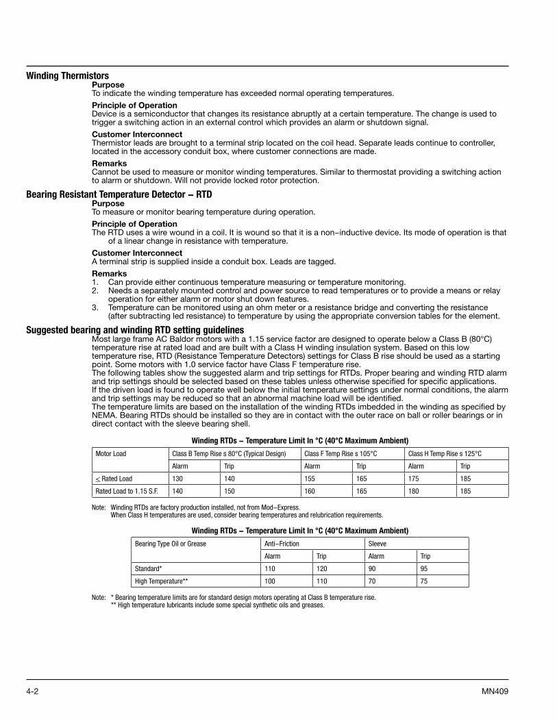
4-2 MN409
Winding ThermistorsPurposeTo indicate the winding temperature has exceeded normal operating temperatures.
Principle of OperationDevice is a semiconductor that changes its resistance abruptly at a certain temperature. The change is used to trigger a switching action in an external control which provides an alarm or shutdown signal.
Customer InterconnectThermistor leads are brought to a terminal strip located on the coil head. Separate leads continue to controller, located in the accessory conduit box, where customer connections are made.
RemarksCannot be used to measure or monitor winding temperatures. Similar to thermostat providing a switching action to alarm or shutdown. Will not provide locked rotor protection.
Bearing Resistant Temperature Detector − RTDPurposeTo measure or monitor bearing temperature during operation.
Principle of OperationThe RTD uses a wire wound in a coil. It is wound so that it is a non−inductive device. Its mode of operation is that
of a linear change in resistance with temperature.
Customer InterconnectA terminal strip is supplied inside a conduit box. Leads are tagged.
Remarks1. Can provide either continuous temperature measuring or temperature monitoring.2. Needs a separately mounted control and power source to read temperatures or to provide a means or relay
operation for either alarm or motor shut down features.3. Temperature can be monitored using an ohm meter or a resistance bridge and converting the resistance
(after subtracting led resistance) to temperature by using the appropriate conversion tables for the element.
Suggested bearing and winding RTD setting guidelinesMost large frame AC Baldor motors with a 1.15 service factor are designed to operate below a Class B (80°C) temperature rise at rated load and are built with a Class H winding insulation system. Based on this low temperature rise, RTD (Resistance Temperature Detectors) settings for Class B rise should be used as a starting point. Some motors with 1.0 service factor have Class F temperature rise.The following tables show the suggested alarm and trip settings for RTDs. Proper bearing and winding RTD alarm and trip settings should be selected based on these tables unless otherwise specified for specific applications.If the driven load is found to operate well below the initial temperature settings under normal conditions, the alarm and trip settings may be reduced so that an abnormal machine load will be identified.The temperature limits are based on the installation of the winding RTDs imbedded in the winding as specified by NEMA. Bearing RTDs should be installed so they are in contact with the outer race on ball or roller bearings or in direct contact with the sleeve bearing shell.
Winding RTDs − Temperature Limit In °C (40°C Maximum Ambient)
Motor Load Class B Temp Rise s 80°C (Typical Design) Class F Temp Rise s 105°C Class H Temp Rise s 125°C
Alarm Trip Alarm Trip Alarm Trip
< Rated Load 130 140 155 165 175 185
Rated Load to 1.15 S.F. 140 150 160 165 180 185
Note: Winding RTDs are factory production installed, not from Mod−Express. When Class H temperatures are used, consider bearing temperatures and relubrication requirements.
Winding RTDs − Temperature Limit In °C (40°C Maximum Ambient)
Bearing Type Oil or Grease Anti−Friction Sleeve
Alarm Trip Alarm Trip
Standard* 110 120 90 95
High Temperature** 100 110 70 75
Note: * Bearing temperature limits are for standard design motors operating at Class B temperature rise. ** High temperature lubricants include some special synthetic oils and greases.
4-3MN409
Bearing Thermocouple − TICPurposeTo measure or monitor bearing temperature during operation.
Principle of OperationThe TIC uses a junction of two dissimilar metals to generate a voltage, which varies linearly with change in junction temperature.
Customer InterconnectUsing the same type of TIC wire, connect to terminal strip posts in separate conduit box.Leads are tagged.
Remarks1. Can provide continuous temperature measuring or temperature monitoring.2. Can also measure temperature by using a potentiometer and converting voltage to temperature by use of the
proper conversion tables.3. Needs separately mounted control and power source to read temperature or to provide a means of relay
operation for either alarm of motor shut down features.
Bearing Thermostat (Also called Bearing Temperature Relay or Gas Bulb Switch)PurposeTo indicate the bearing temperature has exceeded normal operating temperatures.
Principle of OperationThe device operates due to expansion of gas sealed within a sealed gas bulb element which is placed in contact with the bearing housing. As the temperature of the bearing or oil increases, the gas in the element expands and deflects a diaphragm in the switch. The movement of the diaphragm activates the switch contacts. The contacts can be wired directly to a relay to provide either alarm indication or motor shutdown.
ConstructionThe thermostat consists of a set of normally closed or normally open contacts operated by a diaphragm which is connected to a gas bulb through a capillary tube.
Bearing ThermometerPurposeTo measure directly the temperature of the oil in the bearing sump or of the bearing outer race.
Space HeatersWARNING: Space Heaters operate at line voltage. Disconnect power to space heaters before performing maintenance
work on motor. Failure to observe this precaution could result in severe bodily injury or loss of life.PurposeSpace heaters are used to prevent condensation of moisture within the motor enclosure during shutdown or storage periods.
MountingSpace heaters are selected, unless otherwise order, using the following parameters.1. Sheath temperature 350°F (200°C) nominal maximum as standard. Lower Sheath temperatures are available.2. Temperature rise inside of motor raised approximately 10°F (6°C) above ambient.3. Assume ambient maximum of 40°C.
From the above, space heaters are sized, mounted and terminated at an accessory conduit box. Leads are tagged.Approximate Space Heater Wattage for G5000/G315 is 320W, G5810/G40 is 400W, SG50 is 625W and MG50 is 750W.
Oil Circulation SystemPurposeTo provide a source of cool, clean oil to the bearings.If a system is equipped with a variable needle valve to control flow rate, this valve MUST be adjusted.Disconnect valve and adjust to flow rate shown on dimension sheet (available from your Baldor Sales Office.
DescriptionThe oil lubrication system consists of provisions for introducing oil to the bearing and drains which will permit removal of excess oil in the sump without flooding or without letting the sump level become too low for the oil rings to pick up oil in the event the source of oil is lost.Oil inlet and outlets are provided with each bearing to introduce oil into the journal area. An orifice is provided in the oil inlet pipe line to control the amount of oil introduced into the bearing. The oil outlet will provide adequate drain without total loss of oil in the sump.The bearing is also equipped with oil rings.
RequirementThe need for a lubrication system may exist on some ratings due to journal size and speed of the shaft.In those cases the unit would be supplied with inlet and outlet provisions as standard for connection to a customer provided source or oil.The details or ratings that require a flood lubrication system are shown on the dimension sheet.
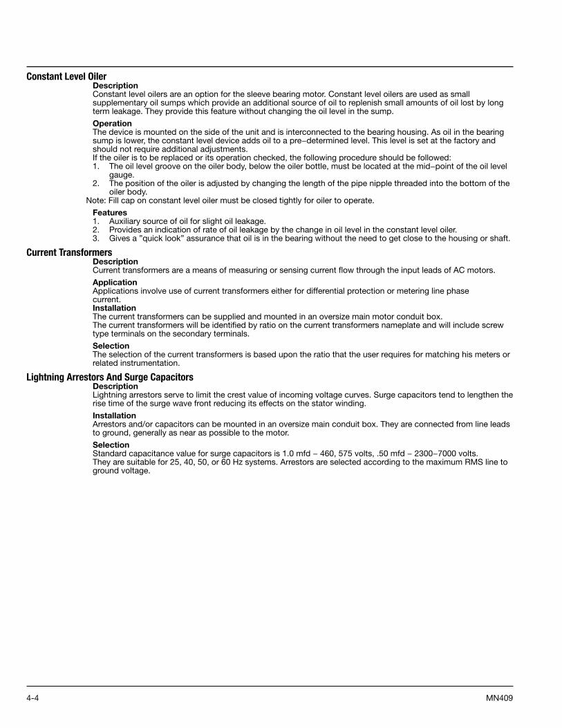
4-4 MN409
Constant Level OilerDescriptionConstant level oilers are an option for the sleeve bearing motor. Constant level oilers are used as small supplementary oil sumps which provide an additional source of oil to replenish small amounts of oil lost by long term leakage. They provide this feature without changing the oil level in the sump.
OperationThe device is mounted on the side of the unit and is interconnected to the bearing housing. As oil in the bearing sump is lower, the constant level device adds oil to a pre−determined level. This level is set at the factory and should not require additional adjustments.If the oiler is to be replaced or its operation checked, the following procedure should be followed:1. The oil level groove on the oiler body, below the oiler bottle, must be located at the mid−point of the oil level
gauge.2. The position of the oiler is adjusted by changing the length of the pipe nipple threaded into the bottom of the
oiler body.Note: Fill cap on constant level oiler must be closed tightly for oiler to operate.
Features1. Auxiliary source of oil for slight oil leakage.2. Provides an indication of rate of oil leakage by the change in oil level in the constant level oiler.3. Gives a ”quick look” assurance that oil is in the bearing without the need to get close to the housing or shaft.
Current TransformersDescriptionCurrent transformers are a means of measuring or sensing current flow through the input leads of AC motors.
ApplicationApplications involve use of current transformers either for differential protection or metering line phasecurrent.InstallationThe current transformers can be supplied and mounted in an oversize main motor conduit box.The current transformers will be identified by ratio on the current transformers nameplate and will include screw type terminals on the secondary terminals.
SelectionThe selection of the current transformers is based upon the ratio that the user requires for matching his meters or related instrumentation.
Lightning Arrestors And Surge CapacitorsDescriptionLightning arrestors serve to limit the crest value of incoming voltage curves. Surge capacitors tend to lengthen the rise time of the surge wave front reducing its effects on the stator winding.
InstallationArrestors and/or capacitors can be mounted in an oversize main conduit box. They are connected from line leads to ground, generally as near as possible to the motor.
SelectionStandard capacitance value for surge capacitors is 1.0 mfd − 460, 575 volts, .50 mfd − 2300−7000 volts.They are suitable for 25, 40, 50, or 60 Hz systems. Arrestors are selected according to the maximum RMS line to ground voltage.
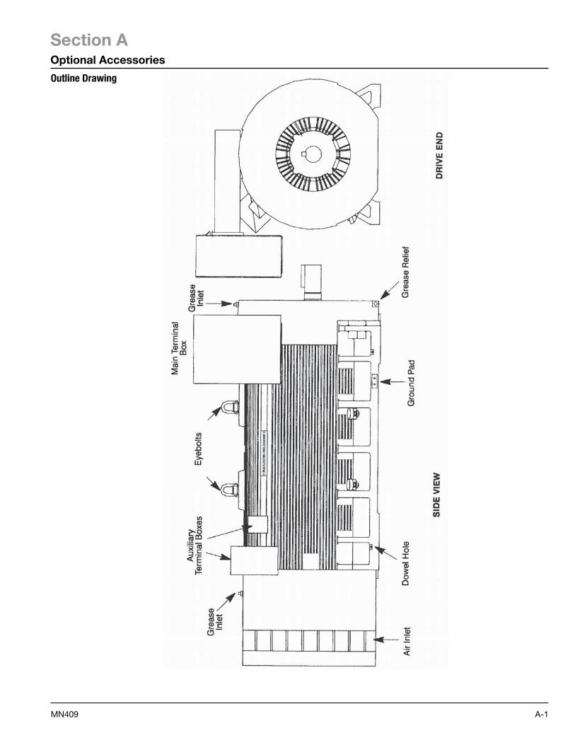
A-1MN409
Section AOptional Accessories
Outline Drawing
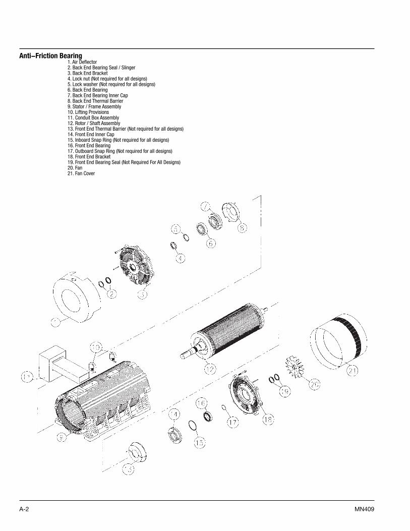
A-2 MN409
Anti−Friction Bearing1. Air Deflector2. Back End Bearing Seal / Slinger3. Back End Bracket4. Lock nut (Not required for all designs)5. Lock washer (Not required for all designs)6. Back End Bearing7. Back End Bearing Inner Cap8. Back End Thermal Barrier9. Stator / Frame Assembly10. Lifting Provisions11. Conduit Box Assembly12. Rotor / Shaft Assembly13. Front End Thermal Barrier (Not required for all designs)14. Front End Inner Cap15. Inboard Snap Ring (Not required for all designs)16. Front End Bearing17. Outboard Snap Ring (Not required for all designs)18. Front End Bracket19. Front End Bearing Seal (Not Required For All Designs)20. Fan21. Fan Cover
A-3MN409
Sleeve Bearing1. Air Deflector2. Shaft Slinger3. Back End Outboard Seal (G50 only)4. Back End Bearing Housing5. Bearing And Oil Ring6. Back End Inboard Bearing Seal (G50 only)7. Bracket Cover8. Float Adjusting Shim (G50 only)9. Sleeve Bearing Bracket10. Stator / Frame Assembly11. Lifting Provisions12. Conduit Box Assembly13. Rotor / Shaft Assembly14. Sleeve Bearing Bracket15. Float Adjusting Shim (G50 only)16. Bracket Cover17. Front End Inboard Seal18. Front End Bearing Housing19. Bearing And Oil Ring20. Front End Outboard Seal (G50 only)21. Front End Bearing Air Seal (G50 only)22. Fan23. Fan Cover

A-4 MN409

Baldor Electric Company
P.O. Box 2400, Fort Smith, AR 72902-2400 U.S.A., Ph: (1) 479.646.4711, Fax (1) 479.648.5792, International Fax (1) 479.648.5895 www.baldor.com
© Baldor Electric CompanyMN409
All Rights Reserved. Printed in USA.6/08