Embed Size (px)
Citation preview
09.05 -
03.11
50470432
EJC B14 / B16
Operating instructions G
EJC B16
EJC B14
3
03
.11
EN
Declaration of Conformity
Jungheinrich AG, Am Stadtrand 35, D-22047 HamburgManufacturer or his authorized representative in the Community
Additional information
Authorised signatory
Date
G EU Declaration of Conformity
The signatories hereby certify that the specified powered industrial truck conforms tothe EU Directive 2006/42/EC (Machine Directive) and 2004/108/EEC (Electro-Magnetic Compatibility, EMC) including their amendments as translated into nationallegislation of the member countries. The signatories are individually empowered ineach case to compile the technical documentation.
Type Option Serial No. Year of construction
EJC B14 EJC B16

03
.11
EN
4
03
.11
EN
4
5
03
.11
EN
Foreword
Notes on the operating instructions
The present ORIGINAL OPERATING INSTRUCTIONS are designed to providesufficient instruction for the safe operation of the industrial truck. The information isprovided clearly and concisely. The chapters are arranged by letter and the pages arenumbered continuously.
The operator manual details different industrial truck models. When operating andservicing the industrial truck, make sure that the particular section applies to yourtruck model.
Our trucks are subject to ongoing development. Jungheinrich reserves the right toalter the design, equipment and technical features of the system. No guarantee ofparticular features of the truck should therefore be assumed from the presentoperating instructions.
Safety notices and text mark-ups
Safety instructions and important explanations are indicated by the followinggraphics:
DANGER!
Indicates an extremely hazardous situation. Failure to comply with this instruction willresult in severe irreparable injury and even death.
WARNING!
Indicates an extremely hazardous situation. Failure to comply with this instructionmay result in severe irreparable injury and even death.
CAUTION!
Indicates a hazardous situation. Failure to comply with this instruction may result inslight to medium injury.
NOTE
Indicates a material hazard. Failure to comply with this instruction may result inmaterial damage.
Z Used before notices and explanations.
Copyright
Copyright of these operating instructions remains with JUNGHEINRICH AG.
t Indicates standard equipment
o Indicates optional equipment

03
.11
EN
6
Jungheinrich Aktiengesellschaft
Am Stadtrand 3522047 Hamburg - Germany
Tel: +49 (0) 40/6948-0
www.jungheinrich.com
03
.11
EN
6
Jungheinrich Aktiengesellschaft
Am Stadtrand 3522047 Hamburg - Germany
Tel: +49 (0) 40/6948-0
www.jungheinrich.com
7
03
.11
EN
Table of Contents
A Correct Use and Application ................................................... 9
1 General.................................................................................................... 92 Correct application................................................................................... 93 Approved application conditions.............................................................. 94 Proprietor responsibilities ........................................................................ 105 Adding attachments and/or accessories.................................................. 10
B Truck Description .................................................................... 11
1 Application ............................................................................................... 111.1 Truck models and rated capacity............................................................. 112 Assemblies and Functional Description................................................... 122.1 Assembly Overview ................................................................................. 122.2 Functional Description ............................................................................. 143 Technical Specifications .......................................................................... 153.1 Performance data .................................................................................... 153.2 Dimensions.............................................................................................. 163.3 Standard mast version EJC B14 ............................................................. 173.4 Standard mast version EJC B16 ............................................................. 173.5 Weights.................................................................................................... 183.6 Tyre type.................................................................................................. 183.7 EN norms................................................................................................. 193.8 Conditions of use..................................................................................... 203.9 Electrical requirements ............................................................................ 204 Identification points and data plates ........................................................ 214.1 Data plate ................................................................................................ 224.2 Truck load chart ....................................................................................... 23
C Transport and Commissioning ................................................ 25
1 Lifting by crane ........................................................................................ 252 Transport ................................................................................................. 263 Using the Truck for the First Time ........................................................... 274 Adjustment of wheel arms ....................................................................... 27
D Battery - Servicing, Recharging, Replacement ....................... 29
1 Safety Regulations Governing the Handling of Lead-Acid Batteries ....... 292 Battery types............................................................................................ 313 Exposing the battery................................................................................ 324 Charging the battery ................................................................................ 334.1 Charging the battery with a stationary charger........................................ 335 Battery removal and installation .............................................................. 35
03
.11
EN
8
E Operation ................................................................................ 37
1 Safety Regulations for the Operation of the Forklift Truck....................... 372 Displays and Controls.............................................................................. 382.1 Battery discharge indicator ...................................................................... 413 Starting up the truck ................................................................................ 423.1 Checks and operations to be performed before starting daily operation . 423.2 Preparing the truck for operation ............................................................. 433.3 Parking the truck securely ....................................................................... 443.4 Battery discharge monitor........................................................................ 444 Industrial Truck Operation ....................................................................... 454.1 Safety regulations for truck operation...................................................... 454.2 Emergency Disconnect, Travel, Steering, Braking .................................. 474.3 Lifting, transporting and depositing loads ................................................ 525 Troubleshooting....................................................................................... 535.1 Truck does not start ................................................................................. 545.2 Load cannot be lifted ............................................................................... 546 Operating the truck without its own drive system .................................... 557 Load handler emergency lowering .......................................................... 568 Optional equipment ................................................................................. 578.1 Fork tines................................................................................................. 578.2 CanCode keypad..................................................................................... 598.3 CANDIS display instrument ..................................................................... 63
F Industrial Truck Maintenance .................................................. 65
1 Operational Safety and Environmental Protection................................... 652 Maintenance Safety Regulations............................................................. 653 Servicing and Inspection ......................................................................... 704 Maintenance checklist ............................................................................. 715 Lubricants and Lubrication Schedule ...................................................... 745.1 Handling consumables safely .................................................................. 745.2 Lubrication Schedule ............................................................................... 765.3 Consumables........................................................................................... 776 Maintenance and repairs ......................................................................... 786.1 Preparing the truck for maintenance and repairs .................................... 786.2 Removing the front panel ........................................................................ 796.3 Checking the hydraulic oil level ............................................................... 806.4 Check the gear oil level ........................................................................... 816.5 Replacing the gauze filter, flushing the gauze filter ................................. 816.6 Checking electrical fuses......................................................................... 826.7 Restoring the truck to service after maintenance and repairs ................. 837 Decommissioning the industrial truck ...................................................... 847.1 Prior to decommissioning ........................................................................ 847.2 Action to be taken during decommissioning ............................................ 867.3 Restoring the truck to service after decommissioning ............................. 878 Final de-commissioning, disposal............................................................ 879 Safety tests to be performed at intervals and after unusual incidents ..... 88

1
0506
.GB
Appendix
JH Traction Battery Operating Instructions
Z These operating instructions apply only to Jungheinrich battery models. If usinganother brand, refer to the manufacturer's operating instructions.
1
0506
.GB
Appendix
JH Traction Battery Operating Instructions
Z These operating instructions apply only to Jungheinrich battery models. If usinganother brand, refer to the manufacturer's operating instructions.

0506
.GB
2
0506
.GB
2
9
03
.11
EN
A Correct Use and Application
1 General
The industrial truck described in the present operating instructions is designed forlifting, lowering and transporting load units.It must be used, operated and serviced in accordance with the present instructions.Any other type of use is beyond the scope of application and can result in damage topersonnel, the industrial truck or property.
2 Correct application
NOTE
The maximum load and load distance are indicated on the load chart and must not beexceeded.The load must rest on the load handler or be lifted by an attachment approved by themanufacturer.The load must rest on the back of the fork carriage and centrally between the forks.
– Lifting and lowering of loads.
– Transporting lowered loads.
– Do not travel with a raised load (>500 mm).
– Do not carry or lift passengers.
– Do push or pull load units.
3 Approved application conditions
– Operation in industrial and commercial environments.
– Permissible temperature range 5°C to 40°C.
– Operation only on secure, level surfaces with sufficient capacity.
– Operation only on routes that are visible and approved by the proprietor.
– Negotiating inclines up to a maximum of 16 %.
– Do not negotiate inclines crosswise or at an angle. Transporting loads downhill.
– Operation in partially public traffic.
Z Special equipment and authorisation is required if the truck is to be used in extremeconditions.The truck is not authorised for use in areas at risk of explosion.
03
.11
EN
10
4 Proprietor responsibilities
For the purposes of the present operating instructions the “proprietor” is defined asany natural or legal person who either uses the industrial truck himself, or on whosebehalf it is used. In special cases (e.g. leasing or renting) the proprietor is consideredthe person who, in accordance with existing contractual agreements between theowner and user of the industrial truck, is charged with operational duties.The proprietor must ensure that the industrial truck is used only for the purpose forwhich it is intended and that there is no danger to life and limb of the user and thirdparties. Furthermore, accident prevention regulations, safety regulations andoperating, servicing and repair guidelines must be followed. The proprietor mustensure that all users have read and understood these operating instructions.
NOTE
Failure to comply with the operating instructions shall invalidate the warranty. Thesame applies if improper work is carried out on the truck by the customer or thirdparties without the permission of the manufacturer.
5 Adding attachments and/or accessories
Adding accessories
The mounting or installation of additional equipment which affects or enhances theperformance of the forklift truck requires the written permission of the manufacturer.Local authority approval may also need to be obtained.Local authority approval does not however constitute the manufacturer’s approval.
11
03
.11
EN
B Truck Description
1 Application
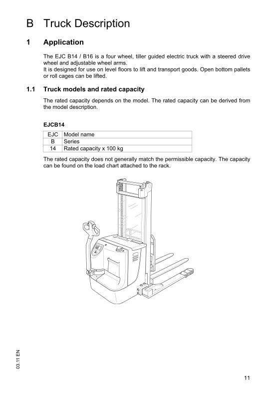
The EJC B14 / B16 is a four wheel, tiller guided electric truck with a steered drivewheel and adjustable wheel arms. It is designed for use on level floors to lift and transport goods. Open bottom palletsor roll cages can be lifted.
1.1 Truck models and rated capacity
The rated capacity depends on the model. The rated capacity can be derived fromthe model description.
The rated capacity does not generally match the permissible capacity. The capacitycan be found on the load chart attached to the rack.
EJCB14
EJC Model name
B Series
14 Rated capacity x 100 kg
11
03
.11
EN
B Truck Description
1 Application
The EJC B14 / B16 is a four wheel, tiller guided electric truck with a steered drivewheel and adjustable wheel arms. It is designed for use on level floors to lift and transport goods. Open bottom palletsor roll cages can be lifted.
1.1 Truck models and rated capacity
The rated capacity depends on the model. The rated capacity can be derived fromthe model description.
The rated capacity does not generally match the permissible capacity. The capacitycan be found on the load chart attached to the rack.
EJCB14
EJC Model name
B Series
14 Rated capacity x 100 kg
03
.11
EN
12
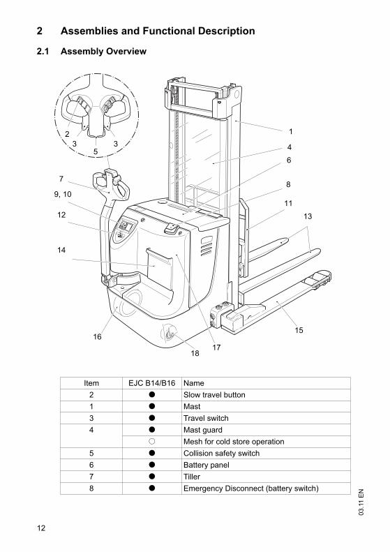
2 Assemblies and Functional Description
2.1 Assembly Overview
Item EJC B14/B16 Name
2 t Slow travel button
1 t Mast
3 t Travel switch
4 t Mast guard
o Mesh for cold store operation
5 t Collision safety switch
6 t Battery panel
7 t Tiller
8 t Emergency Disconnect (battery switch)
1
4
6
8
11
13
15
1718
16
14
12
7
35
3
2
9, 10
03
.11
EN
12
2 Assemblies and Functional Description
2.1 Assembly Overview
Item EJC B14/B16 Name
2 t Slow travel button
1 t Mast
3 t Travel switch
4 t Mast guard
o Mesh for cold store operation
5 t Collision safety switch
6 t Battery panel
7 t Tiller
8 t Emergency Disconnect (battery switch)
1
4
6
8
11
13
15
1718
16
14
12
7
35
3
2
9, 10
13
03
.11
EN
9 t Battery charge / discharge unit
o CANDIS display instrument
10 o CANCODE keypad
11 o Load backrest
12 t Key switch
13 t Fork tines
14 o Document storage compartment
16 t Drive wheel
17 t Front panel
18 t Castor wheel
t= Standard equipment o= Optional equipment
13
03
.11
EN
9 t Battery charge / discharge unit
o CANDIS display instrument
10 o CANCODE keypad
11 o Load backrest
12 t Key switch
13 t Fork tines
14 o Document storage compartment
16 t Drive wheel
17 t Front panel
18 t Castor wheel
t= Standard equipment o= Optional equipment
03
.11
EN
14
2.2 Functional Description
Safety Mechanisms
– An enclosed, smooth truck geometry with rounded edges ensures safe handling ofthe truck.
– The wheels are surrounded by a solid skirt.
– Pressing the Emergency Disconnect rapidly cuts out all electrical functions inhazardous situations.
Hydraulic system
– Lifting and lowering are activated via the lift and lower buttons.
– When lifting is activated, the pump unit starts to operate, supplying hydraulic oilfrom the oil reservoir to the lift cylinder.
– If the truck is fitted with a duplex twin-stage mast (ZZ) or a triplex telescopic mast(DZ) a short, centre-mounted free lift cylinder initially lifts the load carriage (free lift)without changing the overall height of the truck.
Drive system
– A fixed DC motor actuates the drive wheel via a bevel spur gearbox.
– The electronic traction controller ensures smooth drive motor speed control andhence smooth travel, powerful acceleration and electrically controlled braking.
Tiller
– All travel and lift operations can be performed sensitively without having to reach.
– The driver steers with a tiller:
– The drive system can be pivoted +/- 90°.
Electrical system
– 24 volt system.
– Electronic traction control is standard.
Controls and Displays
– Ergonomic controls ensure fatigue-free operation for sensitive application of thetravel and hydraulic operations.
– The battery discharge indicator shows the available battery capacity.
Mast
– The maximum strength steel sections are narrow, allowing for outstanding forkvisibility in particular with the three-stage mast.
– The lift rails and the fork carriage run on permanently-lubricated and hencemaintenance-free angled rollers.
Fork tines
– Alternatively, the truck can be fitted with 2A fork tines.
15
03
.11
EN
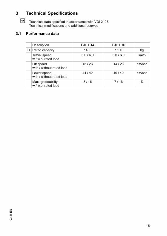
3 Technical Specifications
Z Technical data specified in accordance with VDI 2198.Technical modifications and additions reserved.
3.1 Performance data
Description EJC B14 EJC B16
Q Rated capacity 1400 1600 kg
Travel speed w / w.o. rated load
6,0 / 6,0 6.0 / 6.0 km/h
Lift speed with / without rated load
15 / 23 14 / 23 cm/sec
Lower speedwith / without rated load
44 / 42 40 / 40 cm/sec
Max. gradeabilityw / w.o. rated load
8 / 16 7 / 16 %
15
03
.11
EN
3 Technical Specifications
Z Technical data specified in accordance with VDI 2198.Technical modifications and additions reserved.
3.1 Performance data
Description EJC B14 EJC B16
Q Rated capacity 1400 1600 kg
Travel speed w / w.o. rated load
6,0 / 6,0 6.0 / 6.0 km/h
Lift speed with / without rated load
15 / 23 14 / 23 cm/sec
Lower speedwith / without rated load
44 / 42 40 / 40 cm/sec
Max. gradeabilityw / w.o. rated load
8 / 16 7 / 16 %
03
.11
EN
16
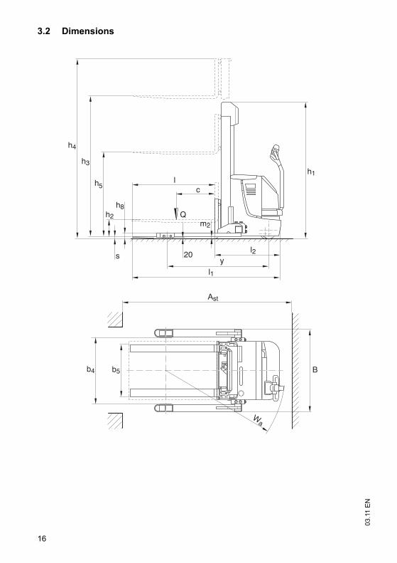
3.2 Dimensions
h4
h3h1
l2
l1
lc
y
Q
h
s
h8
b5
Ast
Wa
B
m2
20
5
h2
b4
03
.11
EN
16
3.2 Dimensions
h4
h3h1
l2
l1
lc
y
Q
h
s
h8
b5
Ast
Wa
B
m2
20
5
h2
b4
17
03
.11
EN
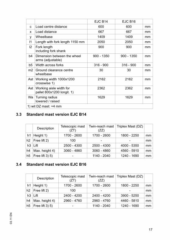
3.3 Standard mast version EJC B14
3.4 Standard mast version EJC B16
EJC B14 EJC B16
c Load centre distance 600 600 mm
x Load distance 667 667 mm
y Wheelbase 1409 1409 mm
l1 Length with fork length 1150 mm 2050 2050 mm
l2 Fork length including fork shank
900 900 mm
b4 Dimension between the wheel arms (adjustable)
900 - 1350 900 - 1350 mm
b5 Width across forks 316 - 900 316 - 900 mm
m2 Ground clearance centre wheelbase
30 30 mm
Ast Working width 1000x1200 crosswise 1)
2162 2162 mm
Ast Working aisle width forpallet 800x1200 longit. 1)
2362 2362 mm
Wa Turning radiuslowered / raised
1629 1629 mm
1) wit DZ mast: +4 mm
DescriptionTelescopic mast
(ZT)Twin-reach mast
(ZZ)Triplex Mast (DZ)
h1 Height 1) 1700 - 2600 1700 - 2600 1800 - 2250 mm
h2 Free lift 2) 100 - - mm
h3 Lift 2500 - 4300 2500 - 4300 4000 - 5350 mm
h4 Max. height 4) 3060 - 4860 3060 - 4860 4560 - 5910 mm
h5 Free lift 3) 5) - 1140 - 2040 1240 - 1690 mm
DescriptionTelescopic mast
(ZT)Twin-reach mast
(ZZ)Triplex Mast (DZ)
h1 Height 1) 1700 - 2600 1700 - 2600 1800 - 2250 mm
h2 Free lift 2) 100 - - mm
h3 Lift 2400 - 4200 2400 - 4200 3900 - 5250 mm
h4 Max. height 4) 2960 - 4760 2960 - 4760 4460 - 5810 mm
h5 Free lift 3) 5) - 1140 - 2040 1240 - 1690 mm
17
03
.11
EN
3.3 Standard mast version EJC B14
3.4 Standard mast version EJC B16
EJC B14 EJC B16
c Load centre distance 600 600 mm
x Load distance 667 667 mm
y Wheelbase 1409 1409 mm
l1 Length with fork length 1150 mm 2050 2050 mm
l2 Fork length including fork shank
900 900 mm
b4 Dimension between the wheel arms (adjustable)
900 - 1350 900 - 1350 mm
b5 Width across forks 316 - 900 316 - 900 mm
m2 Ground clearance centre wheelbase
30 30 mm
Ast Working width 1000x1200 crosswise 1)
2162 2162 mm
Ast Working aisle width forpallet 800x1200 longit. 1)
2362 2362 mm
Wa Turning radiuslowered / raised
1629 1629 mm
1) wit DZ mast: +4 mm
DescriptionTelescopic mast
(ZT)Twin-reach mast
(ZZ)Triplex Mast (DZ)
h1 Height 1) 1700 - 2600 1700 - 2600 1800 - 2250 mm
h2 Free lift 2) 100 - - mm
h3 Lift 2500 - 4300 2500 - 4300 4000 - 5350 mm
h4 Max. height 4) 3060 - 4860 3060 - 4860 4560 - 5910 mm
h5 Free lift 3) 5) - 1140 - 2040 1240 - 1690 mm
DescriptionTelescopic mast
(ZT)Twin-reach mast
(ZZ)Triplex Mast (DZ)
h1 Height 1) 1700 - 2600 1700 - 2600 1800 - 2250 mm
h2 Free lift 2) 100 - - mm
h3 Lift 2400 - 4200 2400 - 4200 3900 - 5250 mm
h4 Max. height 4) 2960 - 4760 2960 - 4760 4460 - 5810 mm
h5 Free lift 3) 5) - 1140 - 2040 1240 - 1690 mm
03
.11
EN
18
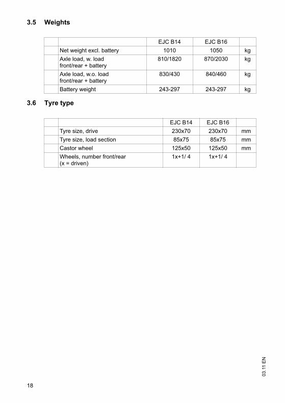
3.5 Weights
3.6 Tyre type
EJC B14 EJC B16
Net weight excl. battery 1010 1050 kg
Axle load, w. loadfront/rear + battery
810/1820 870/2030 kg
Axle load, w.o. loadfront/rear + battery
830/430 840/460 kg
Battery weight 243-297 243-297 kg
EJC B14 EJC B16
Tyre size, drive 230x70 230x70 mm
Tyre size, load section 85x75 85x75 mm
Castor wheel 125x50 125x50 mm
Wheels, number front/rear(x = driven)
1x+1/ 4 1x+1/ 4
03
.11
EN
18
3.5 Weights
3.6 Tyre type
EJC B14 EJC B16
Net weight excl. battery 1010 1050 kg
Axle load, w. loadfront/rear + battery
810/1820 870/2030 kg
Axle load, w.o. loadfront/rear + battery
830/430 840/460 kg
Battery weight 243-297 243-297 kg
EJC B14 EJC B16
Tyre size, drive 230x70 230x70 mm
Tyre size, load section 85x75 85x75 mm
Castor wheel 125x50 125x50 mm
Wheels, number front/rear(x = driven)
1x+1/ 4 1x+1/ 4
19
03
.11
EN
3.7 EN norms
Noise emission level
– EJC B14 / B16: 67 dB(A)
in accordance with EN 12053 as harmonised with ISO 4871.
Z The noise emission level is calculated in accordance with standard procedures andtakes into account the noise level when travelling, lifting and when idle. The noiselevel is measured at the level of the driver's ear.
Electromagnetic compatibility (EMC)
The manufacturer confirms that the truck adheres to the limits for electromagneticemissions and resistance as well as the static electricity discharge test in accordancewith EN 12895 as well as the standardised instructions contained therein.
Z No changes to electric or electronic components or their arrangement may bemade without the written agreement of the manufacturer.
WARNING!
Medical equipment can be damaged by non-ionised radiation
Electrical equipment on the truck emitting non-ionised radiation (e.g. wireless datatransmission) can affect operators' medical equipment (pacemakers, hearing aidsetc.) and result in malfunctions. Consult with a doctor or the medical equipmentmanufacturer to clarify whether it can be used near the industrial truck.
03
.11
EN
20
3.8 Conditions of use
Ambient temperature
– operating at 5°C to 40°C
Z Special equipment and authorisation are required if the truck is to be constantlyused in conditions of extreme temperature or air humidity fluctuations.
3.9 Electrical requirements
The manufacturer certifies compliance with the requirements for the design andmanufacture of electrical equipment, according to EN 1175 "Industrial Truck Safety -Electrical Requirements", provided the truck is used according to its purpose.
21
03
.11
EN
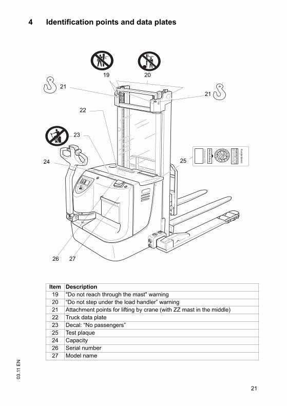
4 Identification points and data plates
Item Description
19 "Do not reach through the mast" warning
20 “Do not step under the load handler” warning
21 Attachment points for lifting by crane (with ZZ mast in the middle)
22 Truck data plate
23 Decal: “No passengers”
25 Test plaque
24 Capacity
26 Serial number
27 Model name
JUNGHEIN
RICH
V
2019
23
24
22
21
26
25
27
21
21
03
.11
EN
4 Identification points and data plates
Item Description
19 "Do not reach through the mast" warning
20 “Do not step under the load handler” warning
21 Attachment points for lifting by crane (with ZZ mast in the middle)
22 Truck data plate
23 Decal: “No passengers”
25 Test plaque
24 Capacity
26 Serial number
27 Model name
JUNGHEIN
RICH
V
2019
23
24
22
21
26
25
27
21
03
.11
EN
22
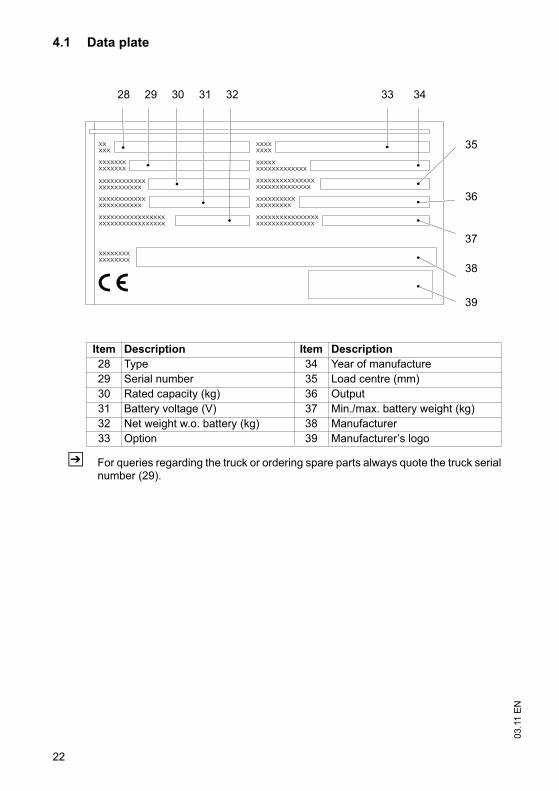
4.1 Data plate
Z For queries regarding the truck or ordering spare parts always quote the truck serialnumber (29).
28 29 3130 32
39
35
38
37
36
3433
Item Description Item Description
28 Type 34 Year of manufacture
29 Serial number 35 Load centre (mm)
30 Rated capacity (kg) 36 Output
31 Battery voltage (V) 37 Min./max. battery weight (kg)
32 Net weight w.o. battery (kg) 38 Manufacturer
33 Option 39 Manufacturer’s logo
03
.11
EN
22
4.1 Data plate
Z For queries regarding the truck or ordering spare parts always quote the truck serialnumber (29).
28 29 3130 32
39
35
38
37
36
3433
Item Description Item Description
28 Type 34 Year of manufacture
29 Serial number 35 Load centre (mm)
30 Rated capacity (kg) 36 Output
31 Battery voltage (V) 37 Min./max. battery weight (kg)
32 Net weight w.o. battery (kg) 38 Manufacturer
33 Option 39 Manufacturer’s logo
23
03
.11
EN
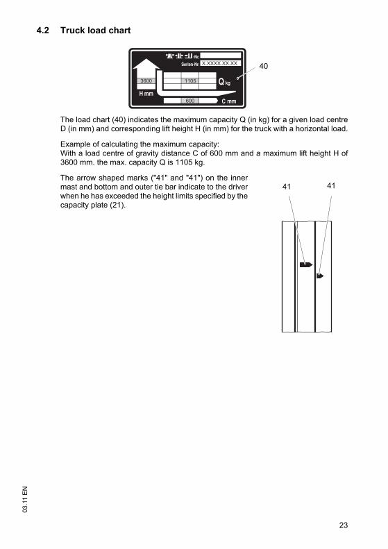
4.2 Truck load chart
The load chart (40) indicates the maximum capacity Q (in kg) for a given load centreD (in mm) and corresponding lift height H (in mm) for the truck with a horizontal load.
Example of calculating the maximum capacity:With a load centre of gravity distance C of 600 mm and a maximum lift height H of3600 mm. the max. capacity Q is 1105 kg.
The arrow shaped marks ("41" and "41") on the innermast and bottom and outer tie bar indicate to the driverwhen he has exceeded the height limits specified by thecapacity plate (21).
600
X.XXXX.XX.XX
11053600
40
41 41
23
03
.11
EN
4.2 Truck load chart
The load chart (40) indicates the maximum capacity Q (in kg) for a given load centreD (in mm) and corresponding lift height H (in mm) for the truck with a horizontal load.
Example of calculating the maximum capacity:With a load centre of gravity distance C of 600 mm and a maximum lift height H of3600 mm. the max. capacity Q is 1105 kg.
The arrow shaped marks ("41" and "41") on the innermast and bottom and outer tie bar indicate to the driverwhen he has exceeded the height limits specified by thecapacity plate (21).
600
X.XXXX.XX.XX
11053600
40
41 41

03
.11
EN
24
03
.11
EN
24
25
03
.11
EN
C Transport and Commissioning
1 Lifting by crane
WARNING!
Improper lifting by crane can result in accidents
The use of unsuitable lifting gear can cause the truck to crash when being lifted bycrane.
Prevent the truck from striking other objects when it is being raised, and avoid anyinvoluntary movements. If necessary secure the truck with guide ropes.
The truck should only be handled by people who are trained in using lifting slingsand tools.
Wear safety shoes when lifting the truck by crane.
Do not stand under a swaying load.
Do not walk into or stand in a hazardous area.
Always use lifting gear with sufficient capacity (for truck weight see truck dataplate).
Always attach the crane slings to the prescribed strap points and prevent them fromslipping.
Use the lifting gear only in the prescribed load direction.
Crane slings should be fastened in such a way that they do not come into contactwith any attachments when lifting.
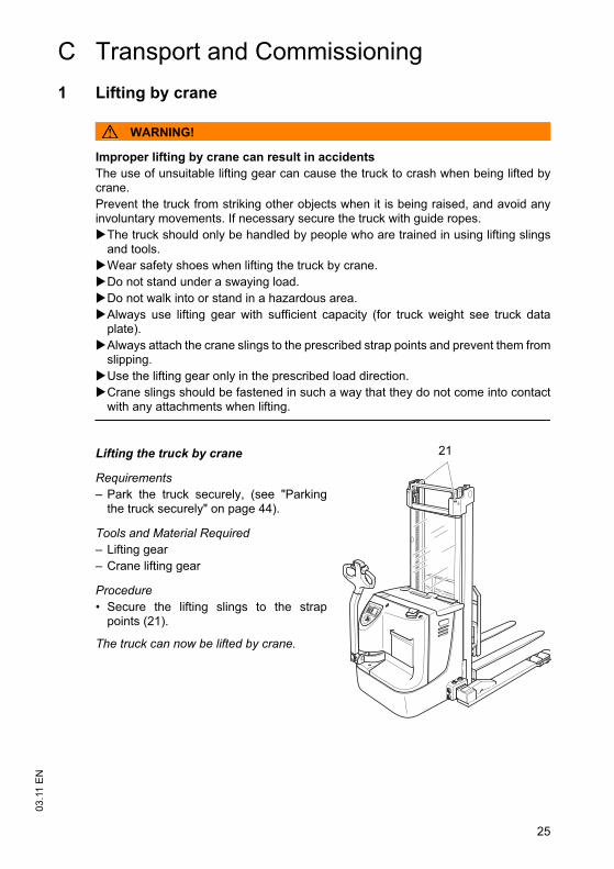
Lifting the truck by crane
Requirements
– Park the truck securely, (see "Parkingthe truck securely" on page 44).
Tools and Material Required
– Lifting gear
– Crane lifting gear
Procedure
• Secure the lifting slings to the strappoints (21).
The truck can now be lifted by crane.
21
25
03
.11
EN
C Transport and Commissioning
1 Lifting by crane
WARNING!
Improper lifting by crane can result in accidents
The use of unsuitable lifting gear can cause the truck to crash when being lifted bycrane.
Prevent the truck from striking other objects when it is being raised, and avoid anyinvoluntary movements. If necessary secure the truck with guide ropes.
The truck should only be handled by people who are trained in using lifting slingsand tools.
Wear safety shoes when lifting the truck by crane.
Do not stand under a swaying load.
Do not walk into or stand in a hazardous area.
Always use lifting gear with sufficient capacity (for truck weight see truck dataplate).
Always attach the crane slings to the prescribed strap points and prevent them fromslipping.
Use the lifting gear only in the prescribed load direction.
Crane slings should be fastened in such a way that they do not come into contactwith any attachments when lifting.
Lifting the truck by crane
Requirements
– Park the truck securely, (see "Parkingthe truck securely" on page 44).
Tools and Material Required
– Lifting gear
– Crane lifting gear
Procedure
• Secure the lifting slings to the strappoints (21).
The truck can now be lifted by crane.
21
03
.11
EN
26
2 Transport
WARNING!
Accidental movement during transport
Improper fastening of the truck and mast during transport can result in seriousaccidents.
Loading must be carried out by specially trained staff in accordance withrecommendations contained in Guidelines VDI 2700 and VDI 2703 In each casecorrect measurements must be made and appropriate safety measures adopted.
The truck must be securely fastened when transported on a lorry or a trailer.
The lorry / trailer must have fastening rings.
Use wedges to prevent the truck from moving.
Use only tension belts or tie-down straps or with sufficient strength.
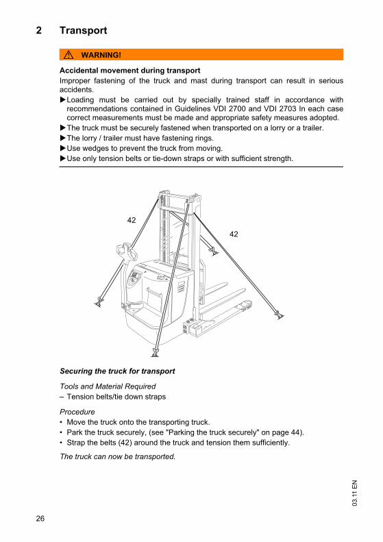
Securing the truck for transport
Tools and Material Required
– Tension belts/tie down straps
Procedure
• Move the truck onto the transporting truck.
• Park the truck securely, (see "Parking the truck securely" on page 44).
• Strap the belts (42) around the truck and tension them sufficiently.
The truck can now be transported.
42
42
03
.11
EN
26
2 Transport
WARNING!
Accidental movement during transport
Improper fastening of the truck and mast during transport can result in seriousaccidents.
Loading must be carried out by specially trained staff in accordance withrecommendations contained in Guidelines VDI 2700 and VDI 2703 In each casecorrect measurements must be made and appropriate safety measures adopted.
The truck must be securely fastened when transported on a lorry or a trailer.
The lorry / trailer must have fastening rings.
Use wedges to prevent the truck from moving.
Use only tension belts or tie-down straps or with sufficient strength.
Securing the truck for transport
Tools and Material Required
– Tension belts/tie down straps
Procedure
• Move the truck onto the transporting truck.
• Park the truck securely, (see "Parking the truck securely" on page 44).
• Strap the belts (42) around the truck and tension them sufficiently.
The truck can now be transported.
42
42
27
03
.11
EN
3 Using the Truck for the First Time
CAUTION!
Only operate the truck with battery current. Rectified AC current will damage theelectronic components. Cable connections to the battery (tow leads) must be lessthan 6 m long and have a minimum cross-section of 50 mm².
Procedure
• Check the equipment is complete.
• If necessary install the battery, (see "Battery removal and installation" on page 35)
• Charge the battery, (see "Charging the battery" on page 33).
The truck can now be started, (see "Starting up the truck" on page 42)
NOTE
Cold store trucks
Trucks designed for use in cold stores have a cold store hydraulic oil and aprotective frame instead of a mast guard on the mast.
If a truck with cold store oil is used outside the cold store, the lowering speeds mayincrease.
4 Adjustment of wheel arms
The distance between the wheel arms is adjustable.
WARNING!
The adjustment of wheel arms must only be performed by a trained servicepersonnel.

03
.11
EN
28
03
.11
EN
28
29
03
.11
EN
D Battery - Servicing, Recharging,
Replacement
1 Safety Regulations Governing the Handling of Lead-AcidBatteries
Maintenance personnel
Batteries may only be charged, serviced or replaced by trained personnel. Thisoperator manual and the manufacturer’s instructions concerning batteries andcharging stations must be observed when carrying out the work.
Fire protection
Do not smoke and avoid naked flames when handling batteries. Wherever anindustrial truck is parked for charging there shall be no inflammable material orlubricants capable of creating sparks within 2 m around the truck. The room must beventilated. Fire protection equipment must be on hand.
Battery maintenance
The battery cell covers must be kept dry and clean. The terminals and cable shoesmust be clean, secure and have a light coating of dielectric grease.
CAUTION!
Before closing the battery panel make sure that the battery cable cannot bedamaged. There is a risk of short circuits with damaged cables.
Battery disposal
Batteries may only be disposed of in accordance with national environmentalprotection regulations or disposal laws. The manufacturer’s disposal instructionsmust be followed.
03
.11
EN
30
WARNING!
Batteries can be hazardous
Batteries contain an acid solution which is poisonous and corrosive. Above all avoidany contact with battery acid.
Dispose of used battery acid in accordance with regulations.
Always wear protective clothing and goggles when working with batteries.
Do not let battery acid come into contact with skin, clothing or eyes. If necessary,rinse with plenty of clean water.
Call for a doctor immediately in the event of physical damage (e.g. skin or eyecontact with battery acid).
Neutralise any spilled battery acid immediately with plenty of water.
Only batteries with a sealed battery container may be used.
Follow national guidelines and legislation.
WARNING!
Using unsuitable batteries can cause accidents
The weight and dimensions of the battery have a considerable effect on theoperational safety and capacity of the industrial truck. Changing the battery featuresrequires the manufacturer’s approval, as compensating weights are required ifsmaller batteries are fitted. When replacing/installing the battery make sure thebattery is securely located in the battery compartment of the truck.
Park the truck securely before carrying out any work on the batteries ((see "Parkingthe truck securely" on page 44)).
31
03
.11
EN
2 Battery types
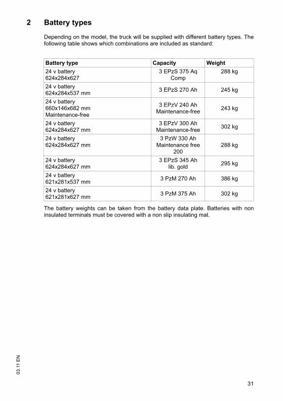
Depending on the model, the truck will be supplied with different battery types. Thefollowing table shows which combinations are included as standard:
The battery weights can be taken from the battery data plate. Batteries with noninsulated terminals must be covered with a non slip insulating mat.
Battery type Capacity Weight
24 v battery624x284x627
3 EPzS 375 Aq Comp
288 kg
24 v battery624x284x537 mm
3 EPzS 270 Ah 245 kg
24 v battery660x146x682 mm Maintenance-free
3 EPzV 240 AhMaintenance-free
243 kg
24 v battery624x284x627 mm
3 EPzV 300 AhMaintenance-free
302 kg
24 v battery624x284x627 mm
3 PzW 330 AhMaintenance free
200288 kg
24 v battery624x284x627 mm
3 EPzS 345 Ahlib. gold
295 kg
24 v battery621x281x537 mm
3 PzM 270 Ah 386 kg
24 v battery621x281x627 mm
3 PzM 375 Ah 302 kg
31
03
.11
EN
2 Battery types
Depending on the model, the truck will be supplied with different battery types. Thefollowing table shows which combinations are included as standard:
The battery weights can be taken from the battery data plate. Batteries with noninsulated terminals must be covered with a non slip insulating mat.
Battery type Capacity Weight
24 v battery624x284x627
3 EPzS 375 Aq Comp
288 kg
24 v battery624x284x537 mm
3 EPzS 270 Ah 245 kg
24 v battery660x146x682 mm Maintenance-free
3 EPzV 240 AhMaintenance-free
243 kg
24 v battery624x284x627 mm
3 EPzV 300 AhMaintenance-free
302 kg
24 v battery624x284x627 mm
3 PzW 330 AhMaintenance free
200288 kg
24 v battery624x284x627 mm
3 EPzS 345 Ahlib. gold
295 kg
24 v battery621x281x537 mm
3 PzM 270 Ah 386 kg
24 v battery621x281x627 mm
3 PzM 375 Ah 302 kg
03
.11
EN
32
3 Exposing the battery
CAUTION!
Trapping hazard
Make sure there is nothing between the battery cover and the truck when you fit thebattery cover.
WARNING!
An unsecured truck can cause accidents
Parking the truck on an incline or with a raised load handler is dangerous and isstrictly prohibited.
Always park the truck on a level surface. In special cases the truck may need to besecured with wedges.
Always fully lower the mast and forks.
Select a place to park where no other people are at risk of injury from loweringforks.
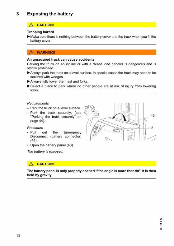
Requirements
– Park the truck on a level surface.
– Park the truck securely, (see"Parking the truck securely" onpage 44).
Procedure
• Pull out the EmergencyDisconnect (battery connector)(44).
• Open the battery panel (43).
The battery is exposed.
CAUTION!
The battery panel is only properly opened if the angle is more than 90°. It is thenheld by gravity.
43
8
03
.11
EN
32
3 Exposing the battery
CAUTION!
Trapping hazard
Make sure there is nothing between the battery cover and the truck when you fit thebattery cover.
WARNING!
An unsecured truck can cause accidents
Parking the truck on an incline or with a raised load handler is dangerous and isstrictly prohibited.
Always park the truck on a level surface. In special cases the truck may need to besecured with wedges.
Always fully lower the mast and forks.
Select a place to park where no other people are at risk of injury from loweringforks.
Requirements
– Park the truck on a level surface.
– Park the truck securely, (see"Parking the truck securely" onpage 44).
Procedure
• Pull out the EmergencyDisconnect (battery connector)(44).
• Open the battery panel (43).
The battery is exposed.
CAUTION!
The battery panel is only properly opened if the angle is more than 90°. It is thenheld by gravity.
43
8
33
03
.11
EN
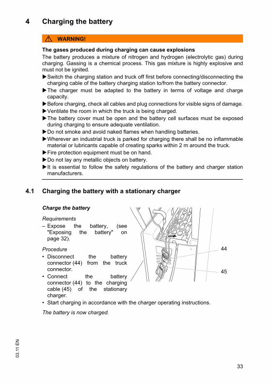
4 Charging the battery
WARNING!
The gases produced during charging can cause explosions
The battery produces a mixture of nitrogen and hydrogen (electrolytic gas) duringcharging. Gassing is a chemical process. This gas mixture is highly explosive andmust not be ignited.
Switch the charging station and truck off first before connecting/disconnecting thecharging cable of the battery charging station to/from the battery connector.
The charger must be adapted to the battery in terms of voltage and chargecapacity.
Before charging, check all cables and plug connections for visible signs of damage.
Ventilate the room in which the truck is being charged.
The battery cover must be open and the battery cell surfaces must be exposedduring charging to ensure adequate ventilation.
Do not smoke and avoid naked flames when handling batteries.
Wherever an industrial truck is parked for charging there shall be no inflammablematerial or lubricants capable of creating sparks within 2 m around the truck.
Fire protection equipment must be on hand.
Do not lay any metallic objects on battery.
It is essential to follow the safety regulations of the battery and charger stationmanufacturers.
4.1 Charging the battery with a stationary charger
Charge the battery
Requirements
– Expose the battery, (see"Exposing the battery" onpage 32).
Procedure
• Disconnect the batteryconnector (44) from the truckconnector.
• Connect the batteryconnector (44) to the chargingcable (45) of the stationarycharger.
• Start charging in accordance with the charger operating instructions.
The battery is now charged.
44
45
33
03
.11
EN
4 Charging the battery
WARNING!
The gases produced during charging can cause explosions
The battery produces a mixture of nitrogen and hydrogen (electrolytic gas) duringcharging. Gassing is a chemical process. This gas mixture is highly explosive andmust not be ignited.
Switch the charging station and truck off first before connecting/disconnecting thecharging cable of the battery charging station to/from the battery connector.
The charger must be adapted to the battery in terms of voltage and chargecapacity.
Before charging, check all cables and plug connections for visible signs of damage.
Ventilate the room in which the truck is being charged.
The battery cover must be open and the battery cell surfaces must be exposedduring charging to ensure adequate ventilation.
Do not smoke and avoid naked flames when handling batteries.
Wherever an industrial truck is parked for charging there shall be no inflammablematerial or lubricants capable of creating sparks within 2 m around the truck.
Fire protection equipment must be on hand.
Do not lay any metallic objects on battery.
It is essential to follow the safety regulations of the battery and charger stationmanufacturers.
4.1 Charging the battery with a stationary charger
Charge the battery
Requirements
– Expose the battery, (see"Exposing the battery" onpage 32).
Procedure
• Disconnect the batteryconnector (44) from the truckconnector.
• Connect the batteryconnector (44) to the chargingcable (45) of the stationarycharger.
• Start charging in accordance with the charger operating instructions.
The battery is now charged.
44
45

03
.11
EN
34
Completing the battery charge, restoring the truck to operation
NOTE
If charging has been interrupted, the full battery capacity will not be available
Requirements
– Battery charging is complete.
Procedure
• Complete charging in accordance with the charger operating instructions.
• Disconnect the battery from the charger.
• Connect the battery to the truck.
The truck is operational again
35
03
.11
EN
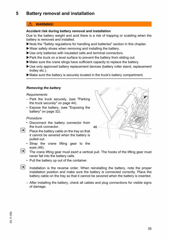
5 Battery removal and installation
WARNING!
Accident risk during battery removal and installation
Due to the battery weight and acid there is a risk of trapping or scalding when thebattery is removed and installed.
Note the "Safety regulations for handling acid batteries" section in this chapter.
Wear safety shoes when removing and installing the battery.
Use only batteries with insulated cells and terminal connectors.
Park the truck on a level surface to prevent the battery from sliding out.
Make sure the crane slings have sufficient capacity to replace the battery.
Use only approved battery replacement devices (battery roller stand, replacementtrolley etc.).
Make sure the battery is securely located in the truck's battery compartment.
Removing the battery
Requirements
– Park the truck securely, (see "Parkingthe truck securely" on page 44).
– Expose the battery, (see "Exposing thebattery" on page 32).
Procedure
• Disconnect the battery connector fromthe truck connector.
Z Place the battery cable on the tray so thatit cannot be severed when the battery ispulled out.
• Strap the crane lifting gear to theeyes (46).
Z The crane lifting gear must exert a vertical pull. The hooks of the lifting gear mustnever fall into the battery cells.
• Pull the battery up out of the container.
Z Installation is the reverse order. When reinstalling the battery, note the properinstallation position and make sure the battery is connected correctly. Place thebattery cable on the tray so that it cannot be severed when the battery is inserted.
– After installing the battery, check all cables and plug connections for visible signsof damage.
46
35
03
.11
EN
5 Battery removal and installation
WARNING!
Accident risk during battery removal and installation
Due to the battery weight and acid there is a risk of trapping or scalding when thebattery is removed and installed.
Note the "Safety regulations for handling acid batteries" section in this chapter.
Wear safety shoes when removing and installing the battery.
Use only batteries with insulated cells and terminal connectors.
Park the truck on a level surface to prevent the battery from sliding out.
Make sure the crane slings have sufficient capacity to replace the battery.
Use only approved battery replacement devices (battery roller stand, replacementtrolley etc.).
Make sure the battery is securely located in the truck's battery compartment.
Removing the battery
Requirements
– Park the truck securely, (see "Parkingthe truck securely" on page 44).
– Expose the battery, (see "Exposing thebattery" on page 32).
Procedure
• Disconnect the battery connector fromthe truck connector.
Z Place the battery cable on the tray so thatit cannot be severed when the battery ispulled out.
• Strap the crane lifting gear to theeyes (46).
Z The crane lifting gear must exert a vertical pull. The hooks of the lifting gear mustnever fall into the battery cells.
• Pull the battery up out of the container.
Z Installation is the reverse order. When reinstalling the battery, note the properinstallation position and make sure the battery is connected correctly. Place thebattery cable on the tray so that it cannot be severed when the battery is inserted.
– After installing the battery, check all cables and plug connections for visible signsof damage.
46

03
.11
EN
36
03
.11
EN
36
37
03
.11
EN
E Operation
1 Safety Regulations for the Operation of theForklift Truck
Driver authorisation
The truck may only be used by suitably trained personnel, who have demonstrated tothe proprietor or his representative that they can drive and handle loads and havebeen authorised to operate the truck by the proprietor or his representative.
Driver’s rights, obligations and responsibilities
The driver must be informed of his duties and responsibilities and be instructed in theoperation of the truck and shall be familiar with the operating instructions. The drivershall be afforded all due rights. Safety shoes must be worn for pedestrian operatedtrucks.
Unauthorised use of truck
The driver is responsible for the truck during the time it is in use. The driver mustprevent unauthorised persons from driving or operating the truck. Do not carrypassengers or lift other people.
Damage and faults
The supervisor must be immediately informed of any damage or faults to the truck orattachment. Trucks which are unsafe for operation (e.g. wheel or brake problems)must not be used until they have been rectified.
Repairs
The driver must not carry out any repairs or alterations to the truck without thenecessary training and authorisation to do so. The driver must never disable or adjustsafety mechanisms or switches.
Hazardous area
WARNING!
Risk of accidents / injury in the hazardous area of the truck
The hazardous area is defined as the area in which a person is at risk due to truckmovement, lifting operations, the load handler (e.g. forks or attachments) or the loaditself. This also includes areas which can be reached by falling loads or loweringoperating equipment.
Instruct unauthorised people to leave the hazardous area.
Give a warning signal with plenty of time for people to leave.
If unauthorised personnel are still within the hazardous area stop the truckimmediately.
Safety devices and warning labels
Safety devices, warning signs ((see "Identification points and data plates" onpage 21)) and warning instructions in the present operating instructions must bestrictly observed.
03
.11
EN
38
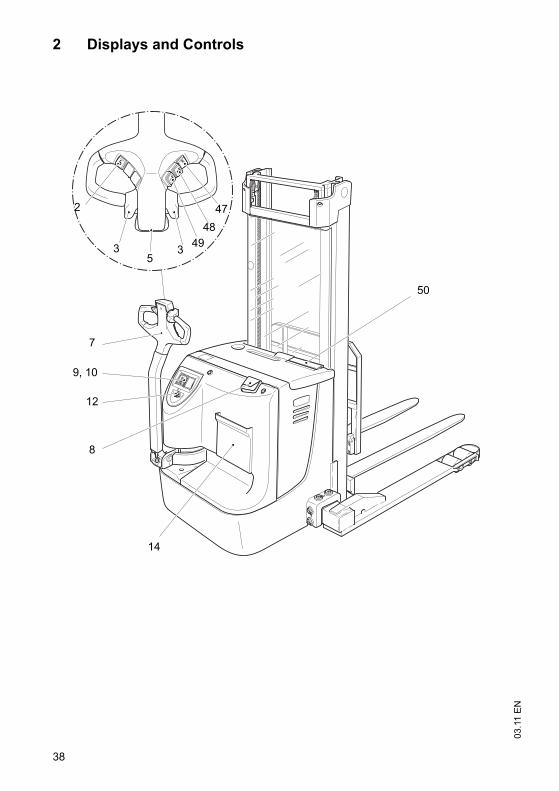
2 Displays and Controls
7
9, 10
12
8
14
50
47
48
493
53
2
03
.11
EN
38
2 Displays and Controls
7
9, 10
12
8
14
50
47
48
493
53
2
39
03
.11
EN
Item
Control / Display EJC B14 EJC B16 Function
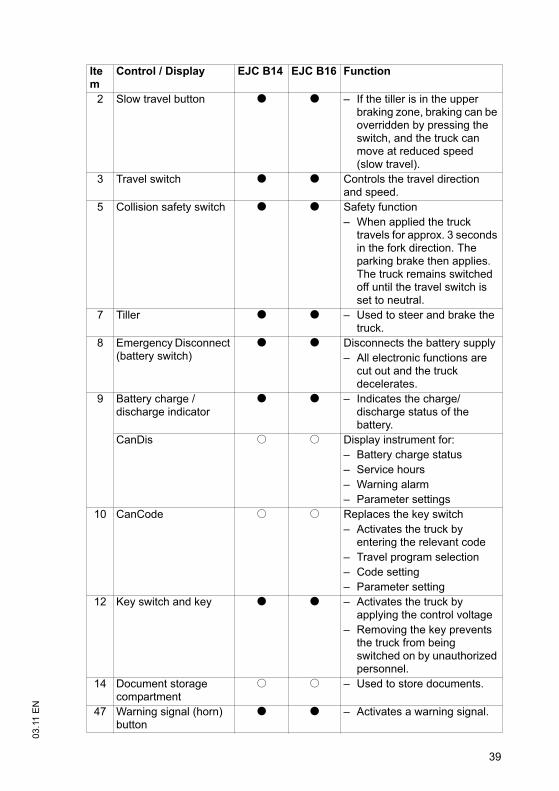
2 Slow travel button t t – If the tiller is in the upper braking zone, braking can be overridden by pressing the switch, and the truck can move at reduced speed (slow travel).
3 Travel switch t t Controls the travel direction and speed.
5 Collision safety switch t t Safety function
– When applied the truck travels for approx. 3 seconds in the fork direction. The parking brake then applies. The truck remains switched off until the travel switch is set to neutral.
7 Tiller t t – Used to steer and brake the truck.
8 Emergency Disconnect (battery switch)
t t Disconnects the battery supply
– All electronic functions are cut out and the truck decelerates.
9 Battery charge / discharge indicator
t t – Indicates the charge/discharge status of the battery.
CanDis o o Display instrument for:
– Battery charge status
– Service hours
– Warning alarm
– Parameter settings
10 CanCode o o Replaces the key switch
– Activates the truck by entering the relevant code
– Travel program selection
– Code setting
– Parameter setting
12 Key switch and key t t – Activates the truck by applying the control voltage
– Removing the key prevents the truck from being switched on by unauthorized personnel.
14 Document storage compartment
o o – Used to store documents.
47 Warning signal (horn) button
t t – Activates a warning signal.
39
03
.11
EN
Item
Control / Display EJC B14 EJC B16 Function
2 Slow travel button t t – If the tiller is in the upper braking zone, braking can be overridden by pressing the switch, and the truck can move at reduced speed (slow travel).
3 Travel switch t t Controls the travel direction and speed.
5 Collision safety switch t t Safety function
– When applied the truck travels for approx. 3 seconds in the fork direction. The parking brake then applies. The truck remains switched off until the travel switch is set to neutral.
7 Tiller t t – Used to steer and brake the truck.
8 Emergency Disconnect (battery switch)
t t Disconnects the battery supply
– All electronic functions are cut out and the truck decelerates.
9 Battery charge / discharge indicator
t t – Indicates the charge/discharge status of the battery.
CanDis o o Display instrument for:
– Battery charge status
– Service hours
– Warning alarm
– Parameter settings
10 CanCode o o Replaces the key switch
– Activates the truck by entering the relevant code
– Travel program selection
– Code setting
– Parameter setting
12 Key switch and key t t – Activates the truck by applying the control voltage
– Removing the key prevents the truck from being switched on by unauthorized personnel.
14 Document storage compartment
o o – Used to store documents.
47 Warning signal (horn) button
t t – Activates a warning signal.
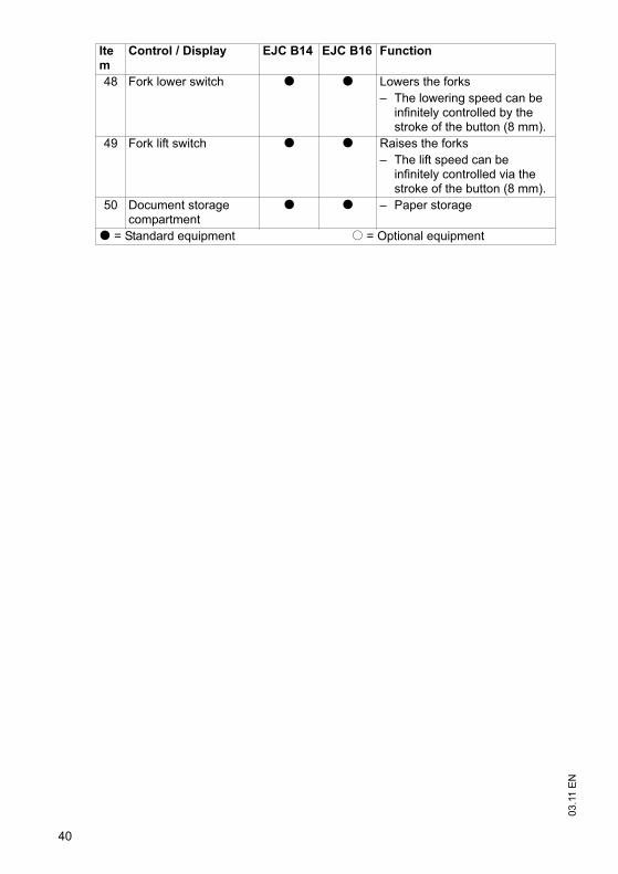
03
.11
EN
40
48 Fork lower switch t t Lowers the forks
– The lowering speed can be infinitely controlled by the stroke of the button (8 mm).
49 Fork lift switch t t Raises the forks
– The lift speed can be infinitely controlled via the stroke of the button (8 mm).
50 Document storage compartment
t t – Paper storage
t = Standard equipment o = Optional equipment
Item
Control / Display EJC B14 EJC B16 Function
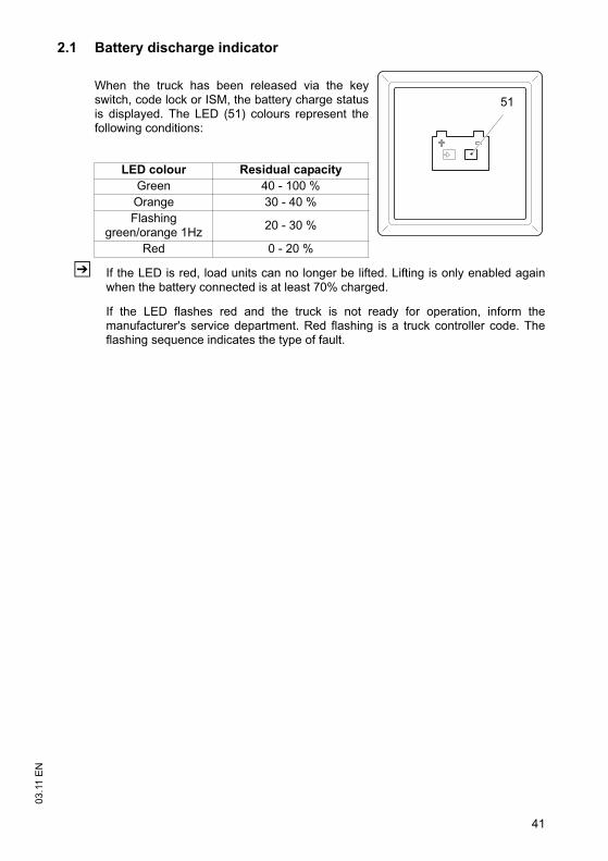
41
03
.11
EN
2.1 Battery discharge indicator
When the truck has been released via the keyswitch, code lock or ISM, the battery charge statusis displayed. The LED (51) colours represent thefollowing conditions:
Z If the LED is red, load units can no longer be lifted. Lifting is only enabled againwhen the battery connected is at least 70% charged.
If the LED flashes red and the truck is not ready for operation, inform themanufacturer's service department. Red flashing is a truck controller code. Theflashing sequence indicates the type of fault.
LED colour Residual capacity
Green 40 - 100 %
Orange 30 - 40 %
Flashinggreen/orange 1Hz
20 - 30 %
Red 0 - 20 %
51
03
.11
EN
42
3 Starting up the truck
3.1 Checks and operations to be performed before starting daily
operation
WARNING!
Damage and other truck or attachment (special equipment) defects can resultin accidents.
If damage or other truck or attachment (special equipment) defects are discoveredduring the following checks, the truck must be taken out of service until it has beenrepaired.
Report any defects immediately to your supervisor.
Tag out and decommission a faulty lift truck.
Only return the truck to service when you have identified and rectified the fault.
Pre-start inspections
Procedure
• Check the whole of the outside of the truck for signs of damage and leaks.Damaged hoses must be replaced immediately.
• Check the battery attachment and wire connections for damage and make surethey are secure.
• Check the battery connector is secure.
• Check the load handler for visible signs of damage such as cracks, bent or severelyworn forks.
• Check the drive wheel and load wheels for damage.
• Check that the markings and labels are present, clean and legible, (see"Identification points and data plates" on page 21).
• Test the Emergency Disconnect switch.
• Check the control handle (damper) is restored to its normal position.
• Check the controls are automatically restored to zero after being applied.
• Test the warning signal.
• Test brakes.
• Test the collision safety switch.
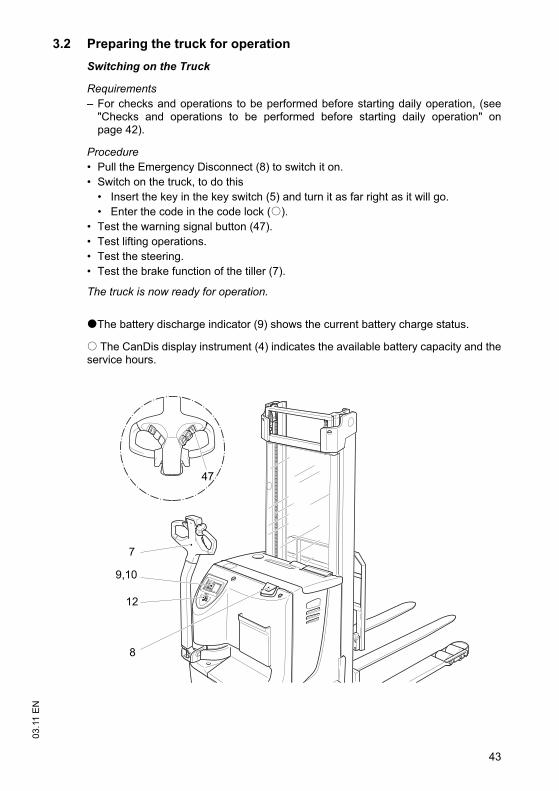
43
03
.11
EN
3.2 Preparing the truck for operation
Switching on the Truck
Requirements
– For checks and operations to be performed before starting daily operation, (see"Checks and operations to be performed before starting daily operation" onpage 42).
Procedure
• Pull the Emergency Disconnect (8) to switch it on.
• Switch on the truck, to do this
• Insert the key in the key switch (5) and turn it as far right as it will go.
• Enter the code in the code lock (o).
• Test the warning signal button (47).
• Test lifting operations.
• Test the steering.
• Test the brake function of the tiller (7).
The truck is now ready for operation.
tThe battery discharge indicator (9) shows the current battery charge status.
o The CanDis display instrument (4) indicates the available battery capacity and theservice hours.
7
9,10
12
8
47
03
.11
EN
44
3.3 Parking the truck securely
WARNING!
An unsecured truck can cause accidents
Parking the truck on an incline, without the brakes applied or with a raised load / loadhandler is dangerous and is strictly prohibited.
Always park the truck on a level surface. In special cases the truck may need to besecured with wedges.
Always fully lower the mast and forks.
Select a place to park where no other people are at risk of injury from loweringforks.
Parking the truck securely
Procedure
• Fully lower the load handler.
• Turn off the key switch and remove the key.
• For CanCode, press the O key.
• Press the Emergency Disconnect.
The truck is parked.
3.4 Battery discharge monitor
Z The standard setting for the battery discharge indicator / discharge monitor isbased on standard batteries. When using maintenance-free or special batteries thedisplay and cutout points of the battery discharge monitor must be set byauthorised specialist personnel. If this adjustment is not made the battery maybecome damaged through excessive depletion.
If the residual capacity falls below the required level, lifting is inhibited. An alternatingdisplay (51) appears. Lifting is only released when the battery connected is at least70% charged.
45
03
.11
EN
4 Industrial Truck Operation
4.1 Safety regulations for truck operation
Travel routes and work areas
Only use lanes and routes specifically designated for truck traffic. Unauthorised thirdparties must stay away from work areas. Loads must only be stored in placesspecially designated for this purpose.The truck must only be operated in work areas with sufficient lighting to avoid dangerto personnel and materials. Additional equipment is necessary to operate the truck inareas of insufficient lighting.
DANGER!
Do not exceed the permissible surface and spot load limits on the travel routes.At blind spots get a second person to assist.The driver must ensure that the loading dock / ramp cannot move or come looseduring loading / unloading.
Travel conduct
The driver must adapt the travel speed to local conditions. The truck must be drivenat slow speed when negotiating bends or narrow passageways, when passingthrough swing doors and at blind spots. The driver must always observe an adequatebraking distance between the forklift truck and the vehicle in front and must be incontrol of the truck at all times. Abrupt stopping (except in emergencies), rapid U turnsand overtaking at dangerous or blind spots are not permitted. Do not lean out or reachbeyond the working and operating area.
Travel visibility
The driver must look in the direction of travel and must always have a clear view ofthe route ahead. Loads that affect visibility must be positioned at the rear of the truck.If this is not possible, a second person must walk alongside the truck as a lookout toobserve the travel route while maintaining eye contact with the driver. Proceed onlyat walking pace and with particular care. Stop the truck as soon as you lose eyecontact.
Negotiating slopes and inclines
Negotiating slopes or inclines is only permitted if they are specifically designed astravel routes, are clean and have a non-slip surface and providing they can be safelytravelled along in accordance with the truck's technical specifications. The truck mustalways be driven with the load unit facing uphill. The industrial truck must not beturned, operated at an angle or parked on inclines or slopes. Inclines must only benegotiated at slow speed, with the driver ready to brake at any moment.
03
.11
EN
46
Negotiating lifts and docks
Lifts may only be entered if they have sufficient capacity, are suitable for driving onand authorised for truck traffic by the owner. The driver must satisfy himself of theabove before entering these areas. The truck must enter lifts with the load in front andmust take up a position which does not allow it to come into contact with the walls ofthe lift shaft. People travelling in the lift with the forklift truck must only enter the liftafter the truck has come to a halt and must exit the lift before the truck. The drivermust ensure that the loading ramp / bridge cannot move or come loose during loading/ unloading.
Type of loads to be carried
The operator must make sure that the load is in a satisfactory condition. Loads mustalways be positioned safely and carefully. Use suitable precautions to prevent partsof the load from tipping or falling down. Prevent liquid loads from sloshing out.
47
03
.11
EN
4.2 Emergency Disconnect, Travel, Steering, Braking
4.2.1 Emergency Disconnect
Applying the Emergency Disconnect
Procedure
CAUTION!
Accident risk
The operation of the Emergency Disconnect switch must not be affected by anyobjects placed in its way.
Z Do not use the Emergency Disconnect (8) as a service brake.
• Press the Emergency Disconnect (8).
All electrical functions are deactivated. The truck brakes to a halt.
Releasing the Emergency Disconnect
Procedure
• Pull the Emergency Disconnect (8) to unlock it.
All electrical functions are enabled and the truck is operational again (assuming thetruck was not operational before the Emergency Disconnect was pressed).For CanCode the truck remains switched off.
4.2.2 Automatic braking
Z When the tiller is released it automatically sets itself to the upper brake zone (B)and automatic braking ensues.
WARNING!
If the tiller moves slowly or not at all to the upper brake zone, the truck must betaken out of service until the cause of this fault is be rectified. Replace the gaspressure spring if necessary.
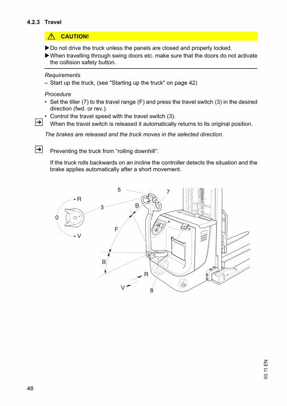
03
.11
EN
48
4.2.3 Travel
CAUTION!
Do not drive the truck unless the panels are closed and properly locked.
When travelling through swing doors etc. make sure that the doors do not activatethe collision safety button.
Requirements
– Start up the truck, (see "Starting up the truck" on page 42)
Procedure
• Set the tiller (7) to the travel range (F) and press the travel switch (3) in the desireddirection (fwd. or rev.).
• Control the travel speed with the travel switch (3).
Z When the travel switch is released it automatically returns to its original position.
The brakes are released and the truck moves in the selected direction.
Z Preventing the truck from “rolling downhill”:
If the truck rolls backwards on an incline the controller detects the situation and thebrake applies automatically after a short movement.
0
R
R
V
B
F
B
V8
3
75
49
03
.11
EN
4.2.4 Slow travel
CAUTION!
The driver must be particularly careful when applying the “slow travel” button (2).The brake is only activated when the "slow travel" button is released and the tiller hasbeen folded.
In hazardous situations brake by immediately releasing the slow travel button (2)and folding the tiller (7).
During "slow travel" you can only brake by inversion braking (travel switch (3)).
The truck can be operated with an upright tiller (7) (e.g. in congested areas / elevator).
Activating slow travel
Procedure
• Press the slow travel switch (2).
• Set the travel switch (3) to the required direction (fwd. or rev.).
The brake is released. The truck travels at slow speed.
Switching off slow travel
Procedure
WARNING!
Accidental acceleration can cause accidents
When you apply the slow travel button in the travel zone "F" and simultaneously pressthe travel switch (3), the truck continues to travel at a faster speed.
• Release the slow travel button (2).
In zone "B" the truck coasts.
• Release the travel switch (3).
Slow travel ends and the brake applies. The truck can now operate again at normalspeed.
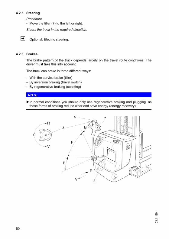
03
.11
EN
50
4.2.5 Steering
Procedure
• Move the tiller (7) to the left or right.
Steers the truck in the required direction.
Z Optional: Electric steering.
4.2.6 Brakes
The brake pattern of the truck depends largely on the travel route conditions. Thedriver must take this into account.
The truck can brake in three different ways:
– With the service brake (tiller)
– By inversion braking (travel switch)
– By regenerative braking (coasting)
NOTE
In normal conditions you should only use regenerative braking and plugging, asthese forms of braking reduce wear and save energy (energy recovery).
0
R
R
V
B
F
B
V
7
8
3
5
51
03
.11
EN
Braking with the service brake
Procedure
• Move the tiller (7) up or down to one of the brake zones (B).
This mechanically brakes the drive motor.
Z When the tiller (7) is released it reverts to the upper braking zone (B). When thetruck is parked, the service brake acts as a parking brake.
Inversion braking
Procedure
• Turn the travel switch (3) to the opposite direction.
The truck brakes regeneratively until it starts to move in the opposite direction.
Z The brake force depends on the position of the travel switch (3).
NOTE
If the controller or drive unit fail, plugging has no effect.
Regenerative braking
Procedure
• On releasing the travel switch (3) – travel switch in neutral position – the truckdecelerates regeneratively via the coasting brake.
The truck brakes to a halt regeneratively via the coasting brake. The service brakethen applies.
CAUTION!
If the coasting brake has been switched off by the service department, only theservice and/or plugging brake can be used.
Parking brake
Z The mechanical brake (parking brake) applies when the truck comes to rest.
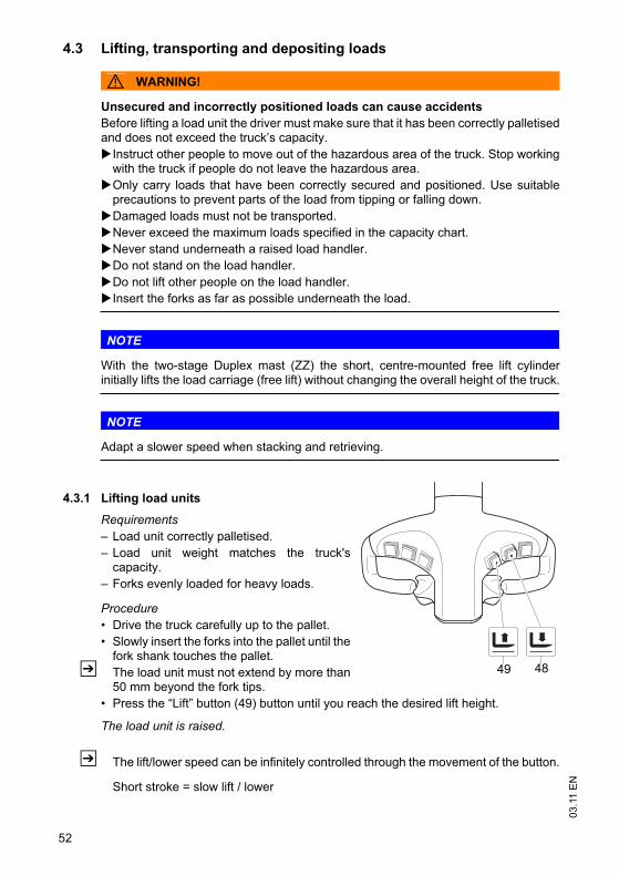
03
.11
EN
52
4.3 Lifting, transporting and depositing loads
WARNING!
Unsecured and incorrectly positioned loads can cause accidents
Before lifting a load unit the driver must make sure that it has been correctly palletisedand does not exceed the truck’s capacity.
Instruct other people to move out of the hazardous area of the truck. Stop workingwith the truck if people do not leave the hazardous area.
Only carry loads that have been correctly secured and positioned. Use suitableprecautions to prevent parts of the load from tipping or falling down.
Damaged loads must not be transported.
Never exceed the maximum loads specified in the capacity chart.
Never stand underneath a raised load handler.
Do not stand on the load handler.
Do not lift other people on the load handler.
Insert the forks as far as possible underneath the load.
NOTE
With the two-stage Duplex mast (ZZ) the short, centre-mounted free lift cylinderinitially lifts the load carriage (free lift) without changing the overall height of the truck.
NOTE
Adapt a slower speed when stacking and retrieving.
4.3.1 Lifting load units
Requirements
– Load unit correctly palletised.
– Load unit weight matches the truck'scapacity.
– Forks evenly loaded for heavy loads.
Procedure
• Drive the truck carefully up to the pallet.
• Slowly insert the forks into the pallet until thefork shank touches the pallet.
Z The load unit must not extend by more than50 mm beyond the fork tips.
• Press the “Lift” button (49) button until you reach the desired lift height.
The load unit is raised.
Z The lift/lower speed can be infinitely controlled through the movement of the button.
Short stroke = slow lift / lower
49 48
53
03
.11
EN
Long stroke = fast lift / lower
CAUTION!
Release the button as soon as you reach the limit position of the load handler.
4.3.2 Transport the load unit.
Transporting load units
Requirements
– Load unit positioned correctly on the forks.
– Mast lowered for transport (approx. 500 mm above the ground).
– Good ground conditions.
Procedure
• Accelerate and decelerate gradually.
• Adapt your travel speed to the conditions of the route and the load you aretransporting.
• Travel at a constant speed.
• Watch out for other traffic at crossings and passageways.
• Always travel with a lookout at blind spots.
• On slopes and inclines always carry the load facing uphill, never approach at anangle or turn.
4.3.3 Lowering the load unit
Depositing load units
NOTE
Loads must not be deposited on travel or escape routes, in front of safetymechanisms or operating equipment that must be accessible at all times.
Requirements
– Warehouse location suitable for storing the load.
Procedure
• Drive carefully up to the storage location.
• Press the “Lower load handler” button (48).
• Carefully lower the load handler so that the forks are clear of the load.
• Carefully remove the forks from the pallet.
The load unit is lowered.
5 Troubleshooting
This chapter enables the user to identify and rectify basic faults and the effects ofincorrect operation. When trying to locate a fault, proceed in the order shown in thetable.
03
.11
EN
54
Z If, after carrying out the following remedial action, the truck cannot be restored tooperation or if a fault in the electronics system is displayed with a correspondingerror code, contact the manufacturer’s service department.Additional troubleshooting must only be performed by the manufacturer’s specialistservice engineers. The manufacturer's customer service department is speciallytrained to carry out these operations.In order for customer services to react quickly and specifically to the fault, thefollowing information is essential:- Truck serial number- Error number on the display unit (if applicable)- Error description- Current location of truck
5.1 Truck does not start
5.2 Load cannot be lifted
Possible Cause Action
– Emergency Disconnect (battery connector) not plugged in.
– Key switch set to O.
– Battery charge too low.
– Faulty fuse.
– Check the Emergency Disconnect (battery connector), and plug it in if necessary.
– Set the key switch to “I”.
– Check the battery charge and charge battery if necessary.
– Check the fuses.
Possible Cause Action
Truck not operational Carry out all measures listed under “Truck does not start”
Hydraulic oil level too low Check the hydraulic oil level
Battery discharge monitor has switched off
Charge the battery
Faulty fuse Check fuses
Excessive load Note maximum capacity, see data plate
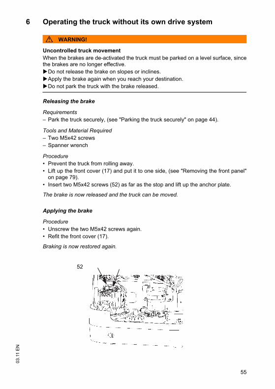
55
03
.11
EN
6 Operating the truck without its own drive system
WARNING!
Uncontrolled truck movement
When the brakes are de-activated the truck must be parked on a level surface, sincethe brakes are no longer effective.
Do not release the brake on slopes or inclines.
Apply the brake again when you reach your destination.
Do not park the truck with the brake released.
Releasing the brake
Requirements
– Park the truck securely, (see "Parking the truck securely" on page 44).
Tools and Material Required
– Two M5x42 screws
– Spanner wrench
Procedure
• Prevent the truck from rolling away.
• Lift up the front cover (17) and put it to one side, (see "Removing the front panel"on page 79).
• Insert two M5x42 screws (52) as far as the stop and lift up the anchor plate.
The brake is now released and the truck can be moved.
Applying the brake
Procedure
• Unscrew the two M5x42 screws again.
• Refit the front cover (17).
Braking is now restored again.
52
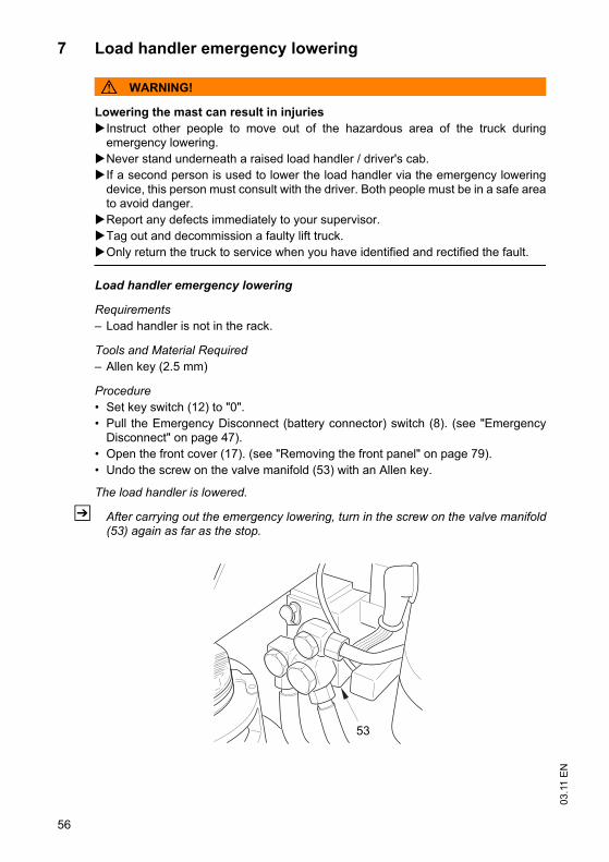
03
.11
EN
56
7 Load handler emergency lowering
WARNING!
Lowering the mast can result in injuries
Instruct other people to move out of the hazardous area of the truck duringemergency lowering.
Never stand underneath a raised load handler / driver's cab.
If a second person is used to lower the load handler via the emergency loweringdevice, this person must consult with the driver. Both people must be in a safe areato avoid danger.
Report any defects immediately to your supervisor.
Tag out and decommission a faulty lift truck.
Only return the truck to service when you have identified and rectified the fault.
Load handler emergency lowering
Requirements
– Load handler is not in the rack.
Tools and Material Required
– Allen key (2.5 mm)
Procedure
• Set key switch (12) to "0".
• Pull the Emergency Disconnect (battery connector) switch (8). (see "EmergencyDisconnect" on page 47).
• Open the front cover (17). (see "Removing the front panel" on page 79).
• Undo the screw on the valve manifold (53) with an Allen key.
The load handler is lowered.
Z After carrying out the emergency lowering, turn in the screw on the valve manifold(53) again as far as the stop.
53
03
.11
EN
56
7 Load handler emergency lowering
WARNING!
Lowering the mast can result in injuries
Instruct other people to move out of the hazardous area of the truck duringemergency lowering.
Never stand underneath a raised load handler / driver's cab.
If a second person is used to lower the load handler via the emergency loweringdevice, this person must consult with the driver. Both people must be in a safe areato avoid danger.
Report any defects immediately to your supervisor.
Tag out and decommission a faulty lift truck.
Only return the truck to service when you have identified and rectified the fault.
Load handler emergency lowering
Requirements
– Load handler is not in the rack.
Tools and Material Required
– Allen key (2.5 mm)
Procedure
• Set key switch (12) to "0".
• Pull the Emergency Disconnect (battery connector) switch (8). (see "EmergencyDisconnect" on page 47).
• Open the front cover (17). (see "Removing the front panel" on page 79).
• Undo the screw on the valve manifold (53) with an Allen key.
The load handler is lowered.
Z After carrying out the emergency lowering, turn in the screw on the valve manifold(53) again as far as the stop.
53
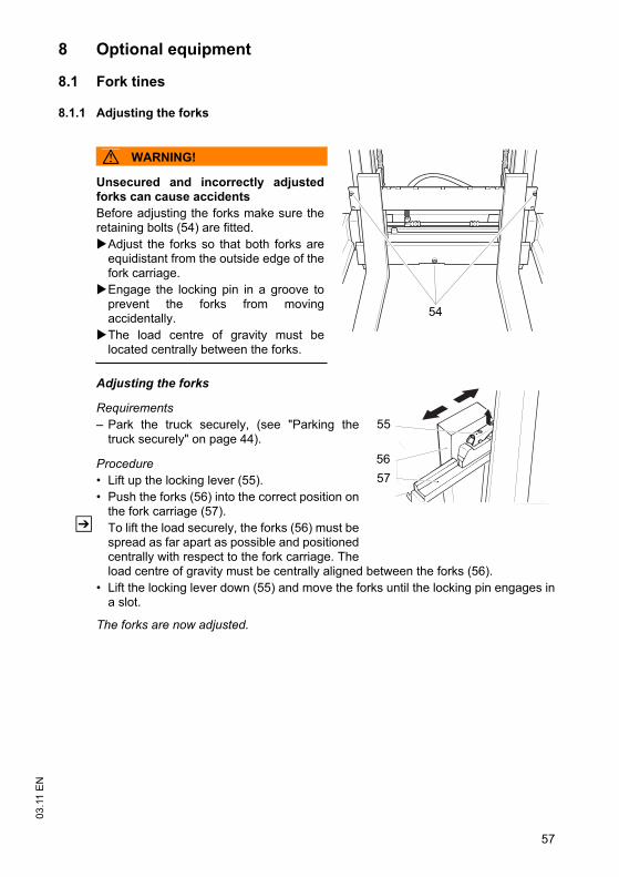
57
03
.11
EN
8 Optional equipment
8.1 Fork tines
8.1.1 Adjusting the forks
WARNING!
Unsecured and incorrectly adjustedforks can cause accidents
Before adjusting the forks make sure theretaining bolts (54) are fitted.
Adjust the forks so that both forks areequidistant from the outside edge of thefork carriage.
Engage the locking pin in a groove toprevent the forks from movingaccidentally.
The load centre of gravity must belocated centrally between the forks.
Adjusting the forks
Requirements
– Park the truck securely, (see "Parking thetruck securely" on page 44).
Procedure
• Lift up the locking lever (55).
• Push the forks (56) into the correct position onthe fork carriage (57).
Z To lift the load securely, the forks (56) must bespread as far apart as possible and positionedcentrally with respect to the fork carriage. Theload centre of gravity must be centrally aligned between the forks (56).
• Lift the locking lever down (55) and move the forks until the locking pin engages ina slot.
The forks are now adjusted.
54
55
56
57
57
03
.11
EN
8 Optional equipment
8.1 Fork tines
8.1.1 Adjusting the forks
WARNING!
Unsecured and incorrectly adjustedforks can cause accidents
Before adjusting the forks make sure theretaining bolts (54) are fitted.
Adjust the forks so that both forks areequidistant from the outside edge of thefork carriage.
Engage the locking pin in a groove toprevent the forks from movingaccidentally.
The load centre of gravity must belocated centrally between the forks.
Adjusting the forks
Requirements
– Park the truck securely, (see "Parking thetruck securely" on page 44).
Procedure
• Lift up the locking lever (55).
• Push the forks (56) into the correct position onthe fork carriage (57).
Z To lift the load securely, the forks (56) must bespread as far apart as possible and positionedcentrally with respect to the fork carriage. Theload centre of gravity must be centrally aligned between the forks (56).
• Lift the locking lever down (55) and move the forks until the locking pin engages ina slot.
The forks are now adjusted.
54
55
56
57
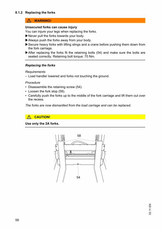
03
.11
EN
58
8.1.2 Replacing the forks
WARNING!
Unsecured forks can cause injury
You can injure your legs when replacing the forks.
Never pull the forks towards your body.
Always push the forks away from your body.
Secure heavy forks with lifting slings and a crane before pushing them down fromthe fork carriage.
After replacing the forks fit the retaining bolts (54) and make sure the bolts areseated correctly. Retaining bolt torque: 70 Nm.
Replacing the forks
Requirements
– Load handler lowered and forks not touching the ground.
Procedure
• Disassemble the retaining screw (54).
• Loosen the fork stop (58).
• Carefully push the forks up to the middle of the fork carriage and lift them out overthe recess.
The forks are now dismantled from the load carriage and can be replaced.
CAUTION!
Use only the 2A forks.
58
54
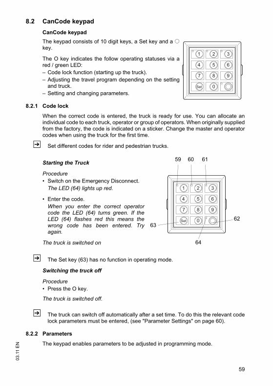
59
03
.11
EN
8.2 CanCode keypad
CanCode keypad
The keypad consists of 10 digit keys, a Set key and a okey.
The O key indicates the follow operating statuses via ared / green LED:
– Code lock function (starting up the truck).
– Adjusting the travel program depending on the settingand truck.
– Setting and changing parameters.
8.2.1 Code lock
When the correct code is entered, the truck is ready for use. You can allocate anindividual code to each truck, operator or group of operators. When originally suppliedfrom the factory, the code is indicated on a sticker. Change the master and operatorcodes when using the truck for the first time.
Z Set different codes for rider and pedestrian trucks.
Starting the Truck
Procedure
• Switch on the Emergency Disconnect.
The LED (64) lights up red.
• Enter the code.
When you enter the correct operatorcode the LED (64) turns green. If theLED (64) flashes red this means thewrong code has been entered. Tryagain.
The truck is switched on
Z The Set key (63) has no function in operating mode.
Switching the truck off
Procedure
• Press the O key.
The truck is switched off.
Z The truck can switch off automatically after a set time. To do this the relevant codelock parameters must be entered, (see "Parameter Settings" on page 60).
8.2.2 Parameters
The keypad enables parameters to be adjusted in programming mode.
1 2 3
4 5 6
7 8 9
0Set
1 2 3
4 5 6
7 8 9
0Set
63
59 60 61
62
64
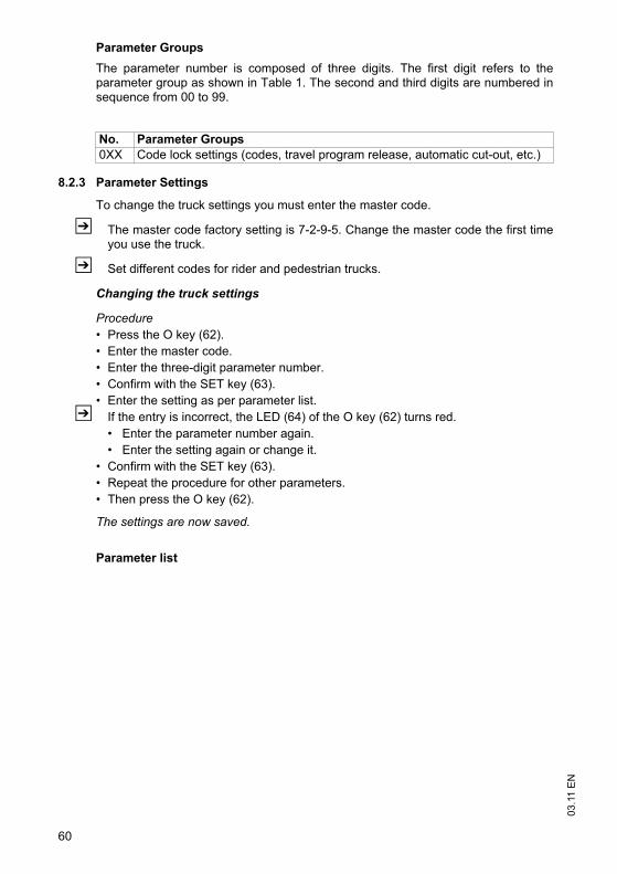
03
.11
EN
60
Parameter Groups
The parameter number is composed of three digits. The first digit refers to theparameter group as shown in Table 1. The second and third digits are numbered insequence from 00 to 99.
8.2.3 Parameter Settings
To change the truck settings you must enter the master code.
Z The master code factory setting is 7-2-9-5. Change the master code the first timeyou use the truck.
Z Set different codes for rider and pedestrian trucks.
Changing the truck settings
Procedure
• Press the O key (62).
• Enter the master code.
• Enter the three-digit parameter number.
• Confirm with the SET key (63).
• Enter the setting as per parameter list.
Z If the entry is incorrect, the LED (64) of the O key (62) turns red.
• Enter the parameter number again.
• Enter the setting again or change it.
• Confirm with the SET key (63).
• Repeat the procedure for other parameters.
• Then press the O key (62).
The settings are now saved.
Parameter list
No. Parameter Groups
0XX Code lock settings (codes, travel program release, automatic cut-out, etc.)
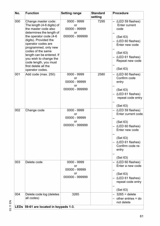
61
03
.11
EN
No. Function Setting range Standard setting
Procedure
000 Change master code: The length (4-6 digits) of the master code also determines the length of the operator code (4-6 digits). Provided the operator codes are programmed, only new codes of the same length can be entered. If you wish to change the code length, you must first delete all the operator codes.
0000 - 9999 or
00000 - 99999 or
000000 - 999999
7295 – (LED 59 flashes) Enter current code
–(Set 63)
– (LED 60 flashes)Enter new code
–(Set 63)
– (LED 61 flashes) Repeat new code
–(Set 63)
001 Add code (max. 250) 0000 - 9999 or
00000 - 99999 or
000000 - 999999
2580 – (LED 60 flashes) Confirm code entry
–(Set 63)
– (LED 61 flashes) repeat code entry
–(Set 63)
002 Change code 0000 - 9999 or
00000 - 99999 or
000000 - 999999
– (LED 59 flashes)Enter current code
–(Set 63)
– (LED 60 flashes)Enter new code
–(Set 63)
– (LED 61 flashes)Confirm code re-entry
–(Set 63)
003 Delete code 0000 - 9999 or
00000 - 99999 or
000000 - 999999
– (LED 60 flashes)Enter a new code
–(Set 63)
– (LED 61 flashes) repeat code entry
–(Set 63)
004 Delete code log (deletes all codes)
3265 – 3265 = delete
– other entries = do not delete
LEDs 59-61 are located in keypads 1-3.

03
.11
EN
62
010 Automatic timeout 00-31 00 – 00 = No timeout
– 01 - 30 = Timeout in minutes
– 31 = Timeout after 10 seconds
No. Function Setting range Standard setting
Procedure
LEDs 59-61 are located in keypads 1-3.
03
.11
EN
62
010 Automatic timeout 00-31 00 – 00 = No timeout
– 01 - 30 = Timeout in minutes
– 31 = Timeout after 10 seconds
No. Function Setting range Standard setting
Procedure
LEDs 59-61 are located in keypads 1-3.
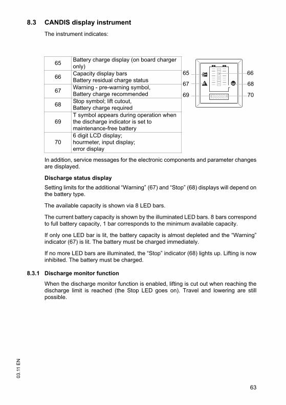
63
03
.11
EN
8.3 CANDIS display instrument
The instrument indicates:
In addition, service messages for the electronic components and parameter changesare displayed.
Discharge status display
Setting limits for the additional “Warning” (67) and “Stop” (68) displays will depend onthe battery type.
The available capacity is shown via 8 LED bars.
The current battery capacity is shown by the illuminated LED bars. 8 bars correspondto full battery capacity, 1 bar corresponds to the minimum available capacity.
If only one LED bar is lit, the battery capacity is almost depleted and the “Warning”indicator (67) is lit. The battery must be charged immediately.
If no more LED bars are illuminated, the “Stop” indicator (68) lights up. Lifting is nowinhibited. The battery must be charged.
8.3.1 Discharge monitor function
When the discharge monitor function is enabled, lifting is cut out when reaching thedischarge limit is reached (the Stop LED goes on). Travel and lowering are stillpossible.
65Battery charge display (on board charger only)
66Capacity display barsBattery residual charge status
67Warning - pre-warning symbol,Battery charge recommended
68Stop symbol; lift cutout,Battery charge required
69T symbol appears during operation when the discharge indicator is set to maintenance-free battery
706 digit LCD display;hourmeter, input display;error display
65
67
69
66
68
70
03
.11
EN
64
8.3.2 Service hour display
Display range between 0.0 and 99,999.0 hours. Travel and lifting operations arelogged. This is a backlit display.
Z For maintenance-free batteries a “T” symbol is shown in the hourmeterdisplay (69).
8.3.3 Error messages
The service hour display is also used for indicating errors. The display starts with a"C" for component and a three digit component number. The error display starts withan ”E” for Error and a three digit error number.If several errors occur simultaneously they are displayed one after the other. Theerrors are displayed until they are rectified. Error messages overwrite the servicehour display. Most errors cause the Emergency Stop to be triggered. The errordisplay remains until the control circuit is switched off (key switch).
Z The manufacturer’s service department has detailed component descriptions witherror codes.
8.3.4 Power up test
On power up the display shows:
– The software version of the display instrument (briefly),
– The service hours,
– The battery charge status.
65
03
.11
EN
F Industrial Truck Maintenance
1 Operational Safety and Environmental Protection
The checks and servicing operations contained in this chapter must be performed inaccordance with the intervals as indicated in the servicing checklists.
WARNING!
Risk of accidents and damage to components
All modifications to the forklift truck assemblies, in particular the safety mechanisms,are prohibited. The operating speeds of the truck must not be increased under anycircumstances.
NOTE
Only original spare parts have been certified by our quality assurance department. Toensure safe and reliable operation of the truck, use only the manufacturer's spareparts.
For safety reasons, only components which have been specially agreed by themanufacturer for this truck may be installed near the computer, controllers and wireguidance sensors (antennae). These components (computers, controllers, wireguidance sensors (antennae)) must therefore not be replaced either by similarcomponents from other trucks of the same series.
2 Maintenance Safety Regulations
Maintenance personnel
The truck should only be serviced and repaired by the manufacturer's specialistcustomer service personnel who have been trained to do this. We thereforerecommend that you enter into a maintenance contract with the manufacturer’s localsales office.
03
.11
EN
66
Lifting and jacking up
WARNING!
Lifting and jacking up the truck safely
In order to raise the truck, the lifting gear must only be secured to the points speciallyprovided for this purpose.
You may only work under a raised load handler / raised cab if they have been securedwith a sufficiently strong chain or the fastening bolt.
In order to raise and jack up the truck safely, proceed as follows:
Jack up the truck only on a level surface and prevent it from moving accidentally.
Always use a jack with sufficient capacity. When jacking up the truck, takeappropriate measures to prevent it from slipping or tipping over (e.g. wedges,wooden blocks).
In order to raise the truck, the lifting gear must only be secured to the pointsspecially provided for this purpose, (see "Transport and Commissioning" onpage 25).
When jacking up the truck, take appropriate measures to prevent it from slipping ortipping over (e.g. wedges, wooden blocks).
Cleaning
CAUTION!
Fire hazard
Do not use flammable liquids to clean the industrial truck.
Always disconnect the battery before starting cleaning work.
Carry out all necessary safety measures to prevent sparking before cleaning (e.g.by short-circuiting).
CAUTION!
Risk of electrical system damage
The electrical system can be damaged if it is cleaning with water. It is prohibited toclean the electrical system with water.
Do not clean the electrical system with water.
Clean the electrical system with weak suction or compressed air (use a compressorwith a water trap) and not a conductive, anti-static brush.
CAUTION!
Risk of component damage when cleaning the truck
If the truck is to be cleaned with a water jet or a high-pressure cleaner, all electricaland electronic components must be carefully covered beforehand as moisture cancause malfunctions. Do not clean with pressurised water.
Z After cleaning, carry out the operations detailed in “Recommissioning the truck aftercleaning or maintenance work” ((see "Restoring the truck to service aftermaintenance and repairs" on page 83)).
67
03
.11
ENElectrical system
WARNING!
Accident risk
Only suitably trained electricians may operate on the truck's electrical system.
Before working on the electrical system, take all precautionary measures to avoidelectric shocks.
Always disconnect the battery before starting cleaning operations.
WARNING!
Electric currents can cause accidents
Make sure the electrical system is voltage-free before starting work on it. Beforestarting maintenance on the electrical system:
Park the truck securely ((see "Parking the truck securely" on page 44)).
Press the Emergency Disconnect.
Disconnect the battery.
Remove any rings or metal bracelets etc. before working on electrical components.
Consumables and used parts
CAUTION!
Consumables and used parts are an environmental hazard
Used parts, oils and fuels must be disposed of in accordance with the relevantenvironmental protection regulations. To change the oil contact the manufacturer'scustomer service department, who have been specially trained for this task.
Note the safety regulations when handling these materials.
Welding
Remove electrical and electronic components from the truck before performingwelding operations, to avoid damage.
Settings
When repairing or replacing hydraulic, electric or electronic components orassemblies, always note the truck-specific settings.
Wheels
WARNING!
The use of wheels that do not match the manufacturer's specifications canresult in accidents.
The quality of wheels affects the stability and performance of the truck.
Uneven wear affects the truck's stability and increases the stopping distance.
When replacing wheels make sure the truck is not skewed.
Always replace wheels in pairs, i.e. left and right at the same time.
67
03
.11
EN
Electrical system
WARNING!
Accident risk
Only suitably trained electricians may operate on the truck's electrical system.
Before working on the electrical system, take all precautionary measures to avoidelectric shocks.
Always disconnect the battery before starting cleaning operations.
WARNING!
Electric currents can cause accidents
Make sure the electrical system is voltage-free before starting work on it. Beforestarting maintenance on the electrical system:
Park the truck securely ((see "Parking the truck securely" on page 44)).
Press the Emergency Disconnect.
Disconnect the battery.
Remove any rings or metal bracelets etc. before working on electrical components.
Consumables and used parts
CAUTION!
Consumables and used parts are an environmental hazard
Used parts, oils and fuels must be disposed of in accordance with the relevantenvironmental protection regulations. To change the oil contact the manufacturer'scustomer service department, who have been specially trained for this task.
Note the safety regulations when handling these materials.
Welding
Remove electrical and electronic components from the truck before performingwelding operations, to avoid damage.
Settings
When repairing or replacing hydraulic, electric or electronic components orassemblies, always note the truck-specific settings.
Wheels
WARNING!
The use of wheels that do not match the manufacturer's specifications canresult in accidents.
The quality of wheels affects the stability and performance of the truck.
Uneven wear affects the truck's stability and increases the stopping distance.
When replacing wheels make sure the truck is not skewed.
Always replace wheels in pairs, i.e. left and right at the same time.
03
.11
EN
68
Z When replacing wheels fitted at the factory, only use the manufacturer’s originalspare parts. Otherwise the truck's rated performance cannot be ensured.
Hydraulic hoses
WARNING!
Brittle hydraulic hose lines can cause accidents
The hoses must be replaced every six years. The manufacturer's customer servicedepartment is specially trained to carry out these operations.
Comply with the safety regulations for hydraulic hose lines in accordance with BGR237.
WARNING!
Hydraulic line leaks can cause accidents
Hydraulic oil can escape from leaky and faulty hydraulic lines.
Report any defects immediately to your supervisor.
Tag out and decommission a faulty lift truck.
Only return the truck to service when you have identified and rectified the fault.
Spilled fluids must be removed immediately with an appropriate bonding agent. Thebonding agent / consumable mixture must be disposed of in accordance withregulations.
WARNING!
Hairline cracks in the hydraulic lines can cause injury and infection
Pressurised hydraulic oil can penetrate the skin through fine holes or hairline cracksin the hydraulic lines, causing severe injury.
Call for a doctor immediately if you are injured.
Do not touch pressurised hydraulic lines.
Report any defects immediately to your supervisor.
Tag out and decommission a faulty lift truck.
Only return the truck to service when you have identified and rectified the fault.
Spilled fluids must be removed immediately with an appropriate bonding agent. Thebonding agent / consumable mixture must be disposed of in accordance withregulations.
69
03
.11
ENLift chains
WARNING!
Non-lubricated and incorrectly cleaned lift chains can cause accidents
Lift chains are safety-critical parts. They must not contain any serious contamination.Lift chains and pivot pins must always be clean and well lubricated.
Lift chains should only be cleaned with paraffin derivatives e.g. petroleum or dieselfuels.
Never clean chains with steam jet high pressure cleaners, cold or chemicalcleaning agents.
Immediately after cleaning, dry the lift chain with compressed air and apply a chainspray.
Always lubricate a chain when it is discharged.
Lubricate a lift chain with particular care around the pulleys.
69
03
.11
EN
Lift chains
WARNING!
Non-lubricated and incorrectly cleaned lift chains can cause accidents
Lift chains are safety-critical parts. They must not contain any serious contamination.Lift chains and pivot pins must always be clean and well lubricated.
Lift chains should only be cleaned with paraffin derivatives e.g. petroleum or dieselfuels.
Never clean chains with steam jet high pressure cleaners, cold or chemicalcleaning agents.
Immediately after cleaning, dry the lift chain with compressed air and apply a chainspray.
Always lubricate a chain when it is discharged.
Lubricate a lift chain with particular care around the pulleys.
03
.11
EN
70
3 Servicing and Inspection
Thorough and expert servicing is one of the most important requirements for the safeoperation of the industrial truck. Failure to perform regular servicing can lead to truckfailure and poses a potential hazard to personnel and equipment.
WARNING!
The application conditions of an industrial truck have a considerable impact on thewear of the service components.We recommend that a Jungheinrich customer service adviser carries out anapplication analysis on site to work out specific service intervals to prevent damagedue to wear.The service intervals stated are based on single shift operation under normaloperating conditions. They must be reduced accordingly if the truck is to be used inconditions of extreme dust, temperature fluctuations or multiple shifts.
The following servicing checklist indicates the operations to be performed and therespective intervals to be observed. Maintenance intervals are defined as:
Z W maintenance intervals must be performed by the owner.
During the run-in period – after approx. 100 service hours – the owner must check thewheel nuts / bolts and re-tighten if necessary.
W = Every 50 service hours, at least weekly
A = Every 500 service hours
B = Every 1000 service hours, or at least annually
C = Every 2000 service hours, or at least annually
t = Standard maintenance interval
k =Cold store maintenance interval (in addition to standard maintenance interval)
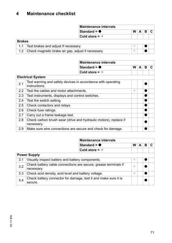
71
03
.11
EN
4 Maintenance checklist
Maintenance intervals
Standard = t W A B C
Cold store = k
Brakes
1.1 Test brakes and adjust if necessary. k t
1.2 Check magnetic brake air gap, adjust if necessary. k t
Maintenance intervals
Standard = t W A B C
Cold store = k
Electrical System
2.1Test warning and safety devices in accordance with operating instructions.
t
2.2 Test the cables and motor attachments. k t
2.3 Test instruments, displays and control switches. t
2.4 Test the switch setting. t
2.5 Check contactors and relays. t
2.6 Check fuse ratings. t
2.7 Carry out a frame leakage test. t
2.8 Check carbon brush wear (drive and hydraulic motors), replace if necessary.
t
2.9 Make sure wire connections are secure and check for damage. t
Maintenance intervals
Standard = t W A B C
Cold store = k
Power Supply
3.1 Visually inspect battery and battery components. k t
3.2Check battery cable connections are secure, grease terminals if necessary.
k t
3.3 Check acid density, acid level and battery voltage. k t
3.4Check battery connector for damage, test it and make sure it is secure.
t
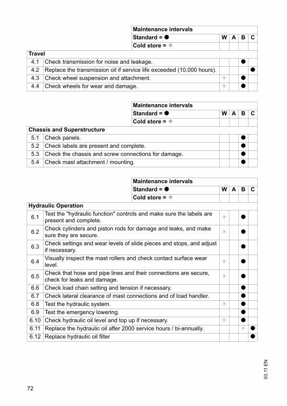
03
.11
EN
72
Maintenance intervals
Standard = t W A B C
Cold store = k
Travel
4.1 Check transmission for noise and leakage. t
4.2 Replace the transmission oil if service life exceeded (10,000 hours). t
4.3 Check wheel suspension and attachment. k t
4.4 Check wheels for wear and damage. k t
Maintenance intervals
Standard = t W A B C
Cold store = k
Chassis and Superstructure
5.1 Check panels. t
5.2 Check labels are present and complete. t
5.3 Check the chassis and screw connections for damage. t
5.4 Check mast attachment / mounting. t
Maintenance intervals
Standard = t W A B C
Cold store = k
Hydraulic Operation
6.1Test the "hydraulic function" controls and make sure the labels are present and complete.
k t
6.2Check cylinders and piston rods for damage and leaks, and make sure they are secure.
k t
6.3Check settings and wear levels of slide pieces and stops, and adjust if necessary.
t
6.4Visually inspect the mast rollers and check contact surface wear level.
k t
6.5Check that hose and pipe lines and their connections are secure, check for leaks and damage.
k t
6.6 Check load chain setting and tension if necessary. t
6.7 Check lateral clearance of mast connections and of load handler. t
6.8 Test the hydraulic system. k t
6.9 Test the emergency lowering. t
6.10 Check hydraulic oil level and top up if necessary. k t
6.11 Replace the hydraulic oil after 2000 service hours / bi-annually. k t
6.12 Replace hydraulic oil filter t
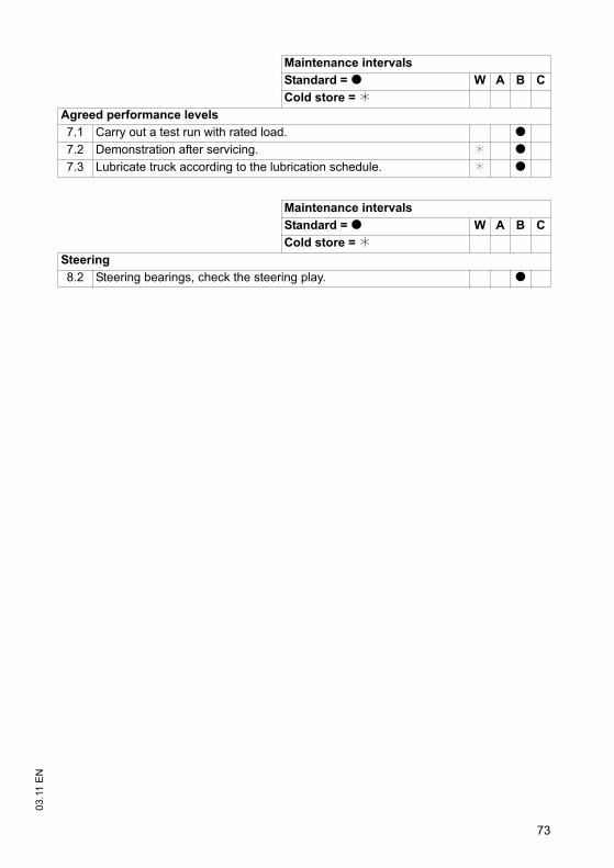
73
03
.11
EN
Maintenance intervals
Standard = t W A B C
Cold store = k
Agreed performance levels
7.1 Carry out a test run with rated load. t
7.2 Demonstration after servicing. k t
7.3 Lubricate truck according to the lubrication schedule. k t
Maintenance intervals
Standard = t W A B C
Cold store = k
Steering
8.2 Steering bearings, check the steering play. t

03
.11
EN
74
5 Lubricants and Lubrication Schedule
5.1 Handling consumables safely
Handling consumables
Consumables must always be handled correctly. Follow the manufacturer’sinstructions.
WARNING!
Improper handling is hazardous to health, life and the environment
Consumables can be flammable.
Keep consumables away from hot components and naked flames.
Always keep consumables in prescribed containers.
Always fill consumables in clean containers.
Do not mix up different grades of consumable. The only exception to this is whenmixing is expressly stipulated in the operating instructions.
CAUTION!
Spilled liquids can cause slipping and endanger the environment
Risk of slipping from spilled liquids. The risk is greater when combined with water.
Do not spill fluids.
Spilled fluids must be removed immediately with an appropriate bonding agent.
The bonding agent / consumable mixture must be disposed of in accordance withregulations.
WARNING!
Oils (chain spray / hydraulic oil) are flammable and poisonous.
Dispose of used oils in accordance with regulations. Store used oil safely until it canbe disposed of in accordance with regulations.
Do not spill oil.
Spilled fluids must be removed immediately with an appropriate bonding agent.
The bonding agent / consumable mixture must be disposed of in accordance withregulations.
Observe national regulations when handling oils.
Wear safety gloves when handling oils.
Prevent oil from coming into contact with hot motor parts.
Do not smoke when handling oil.
Avoid contact and digestion. If you swallow oil do not induce vomiting but call for adoctor immediately.
Seek fresh air after breathing in oil fumes or vapours.
If oil has come into contact with your skin, rinse your skin with water.
If oil has come into contact with your eyes, rinse them with water and call for adoctor immediately.
Replace oil-soaked clothing and shoes immediately.
75
03
.11
ENConsumables and used parts
CAUTION!
Consumables and used parts are an environmental hazard
Used parts, oils and fuels must be disposed of in accordance with the relevantenvironmental protection regulations. To change the oil contact the manufacturer'scustomer service department, who have been specially trained for this task.
Note the safety regulations when handling these materials.
75
03
.11
EN
Consumables and used parts
CAUTION!
Consumables and used parts are an environmental hazard
Used parts, oils and fuels must be disposed of in accordance with the relevantenvironmental protection regulations. To change the oil contact the manufacturer'scustomer service department, who have been specially trained for this task.
Note the safety regulations when handling these materials.
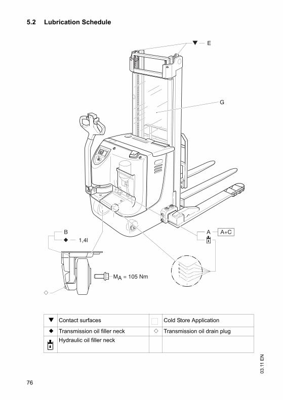
03
.11
EN
76
5.2 Lubrication Schedule
g Contact surfaces Cold Store Application
b Transmission oil filler neck a Transmission oil drain plug
Hydraulic oil filler neck
B1,4l
MA = 105 Nm
B+C
G
A A+C
E F
03
.11
EN
76
5.2 Lubrication Schedule
g Contact surfaces Cold Store Application
b Transmission oil filler neck a Transmission oil drain plug
Hydraulic oil filler neck
B1,4l
MA = 105 Nm
B+C
G
A A+C
E F
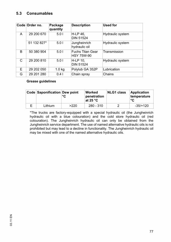
77
03
.11
EN
5.3 Consumables
Grease guidelines
*The trucks are factory-equipped with a special hydraulic oil (the Jungheinrichhydraulic oil with a blue colouration) and the cold store hydraulic oil (redcolouration). The Jungheinrich hydraulic oil can only be obtained from theJungheinrich service department. The use of named alternative hydraulic oils is notprohibited but may lead to a decline in functionality. The Jungheinrich hydraulic oilmay be mixed with one of the named alternative hydraulic oils.
Code Order no. Package quantity
Description Used for
A 29 200 670 5.0 l H-LP 46, DIN 51524
Hydraulic system
51 132 827* 5.0 l Jungheinrich hydraulic oil
Hydraulic system
B 50 380 904 5.0 l Fuchs Titan Gear HSY 75W-90
Transmission
C 29 200 810 5.0 l H-LP 10, DIN 51524
Hydraulic system
E 29 202 050 1.0 kg Polylub GA 352P Lubrication
G 29 201 280 0.4 l Chain spray Chains
Code Saponification Dew point°C
Worked penetrationat 25 °C
NLG1 class Application temperature °C
E Lithium >220 280 - 310 2 -35/+120
03
.11
EN
78
6 Maintenance and repairs
6.1 Preparing the truck for maintenance and repairs
All necessary safety measures must be taken to avoid accidents when carrying outmaintenance and repairs. The following preparations must be made:
Procedure
• Park the truck on a level surface.
• Fully lower the main and auxiliary lift.
• Park the truck securely, (see "Parking the truck securely" on page 44).
• Disconnect the battery to prevent the truck from being switched on accidentally.
• When working under a raised lift truck, secure it to prevent it from lowering, tippingor sliding away.
WARNING!
Risk of accidents when working under the load handler, driver's cab and lifttruck
When working under a raised load handler, driver's cab or a raised truck, securethem to prevent the truck from from lowering, tipping or sliding away.
When raising the truck, follow the instructions, (see "Transport andCommissioning" on page 25). When working on the parking brake, prevent thetruck from accidentally rolling away (e.g. with wedges).
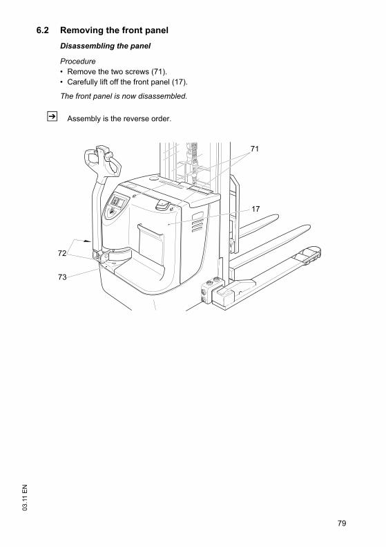
79
03
.11
EN
6.2 Removing the front panel
Disassembling the panel
Procedure
• Remove the two screws (71).
• Carefully lift off the front panel (17).
The front panel is now disassembled.
Z Assembly is the reverse order.
17
71
73
72
79
03
.11
EN
6.2 Removing the front panel
Disassembling the panel
Procedure
• Remove the two screws (71).
• Carefully lift off the front panel (17).
The front panel is now disassembled.
Z Assembly is the reverse order.
17
71
73
72
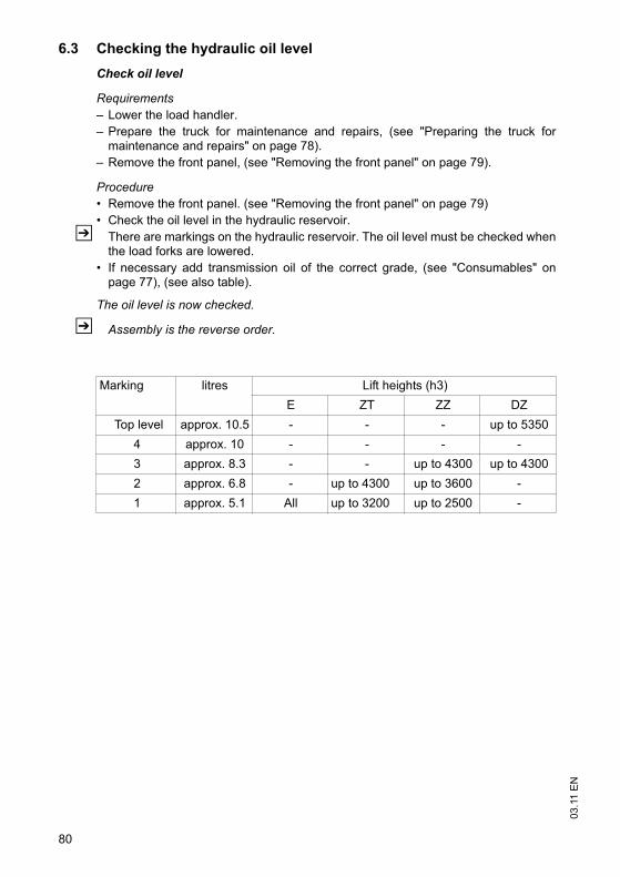
03
.11
EN
80
6.3 Checking the hydraulic oil level
Check oil level
Requirements
– Lower the load handler.
– Prepare the truck for maintenance and repairs, (see "Preparing the truck formaintenance and repairs" on page 78).
– Remove the front panel, (see "Removing the front panel" on page 79).
Procedure
• Remove the front panel. (see "Removing the front panel" on page 79)
• Check the oil level in the hydraulic reservoir.
Z There are markings on the hydraulic reservoir. The oil level must be checked whenthe load forks are lowered.
• If necessary add transmission oil of the correct grade, (see "Consumables" onpage 77), (see also table).
The oil level is now checked.
Z Assembly is the reverse order.
Marking litres Lift heights (h3)
E ZT ZZ DZ
Top level approx. 10.5 - - - up to 5350
4 approx. 10 - - - -
3 approx. 8.3 - - up to 4300 up to 4300
2 approx. 6.8 - up to 4300 up to 3600 -
1 approx. 5.1 All up to 3200 up to 2500 -
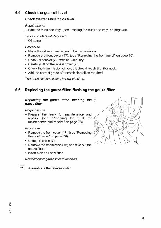
81
03
.11
EN
6.4 Check the gear oil level
Check the transmission oil level
Requirements
– Park the truck securely, (see "Parking the truck securely" on page 44).
Tools and Material Required
– Oil sump
Procedure
• Place the oil sump underneath the transmission
• Remove the front cover (17), (see "Removing the front panel" on page 79).
• Undo 2 x screws (72) with an Allen key.
• Carefully lift off the wheel cover (73).
• Check the transmission oil level. It should reach the filler neck.
• Add the correct grade of transmission oil as required.
The transmission oil level is now checked.
6.5 Replacing the gauze filter, flushing the gauze filter
Replacing the gauze filter, flushing thegauze filter
Requirements
– Prepare the truck for maintenance andrepairs. (see "Preparing the truck formaintenance and repairs" on page 78).
Procedure
• Remove the front cover (17). (see "Removingthe front panel" on page 79).
• Undo the union (74).
• Remove the connection (75) and take out thegauze filter.
• insert a clean / new filter.
New/ cleaned gauze filter is inserted.
Z Assembly is the reverse order.
74 75
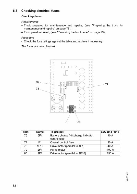
03
.11
EN
82
6.6 Checking electrical fuses
Checking fuses
Requirements
– Truck prepared for maintenance and repairs, (see "Preparing the truck formaintenance and repairs" on page 78).
– Front panel removed, (see "Removing the front panel" on page 79).
Procedure
• Check the fuse ratings against the table and replace if necessary.
The fuses are now checked.
Item Name To protect EJC B14 / B16
76 6F1 Battery charge / discharge indicator control fuse
10 A
77 F1 Overall control fuse 10 A
78 1F10 Drive motor (parallel to 1F1) 40 A
79 2F1 Pump motor 150 A
80 1F1 Drive motor (parallel to 1F10) 150 A
79
76
78
77
80
83
03
.11
EN
6.7 Restoring the truck to service after maintenance and repairs
Procedure
• Thoroughly clean the truck.
• Lubricate the truck according to the lubrication schedule, (see "LubricationSchedule" on page 76).
• Clean the battery, grease the terminals and connect the battery.
• Charge the battery, (see "Charging the battery" on page 33).
• Check the transmission oil for condensation water and replace if necessary.
• Check the hydraulic oil for condensation water and replace if necessary.
Z The manufacturer's customer service department is specially trained to carry outthese operations.
WARNING!
Faulty brakes can cause accidents
As soon as the truck has been started, test the brakes several times.
Report any defects immediately to your supervisor.
Tag out and decommission a faulty lift truck.
Only return the truck to service when you have identified and rectified the fault.
• Start up the truck, (see "Starting up the truck" on page 42).
Z If there are switching problems in the electrical system, apply contact spray to theexposed contacts and remove any oxide layers on the contacts of the controls byapplying them repeatedly.
03
.11
EN
84
7 Decommissioning the industrial truck
Z If the truck is to be out of service for more than a month, e.g. for commercialreasons, it must be stored in a frost-free and dry room. All necessary measuresmust be taken before, during and after decommissioning as described hereafter.
WARNING!
Lifting and jacking up the truck safely
In order to raise the truck, the lifting gear must only be secured to the points speciallyprovided for this purpose.
You may only work under a raised load handler / raised cab if they have been securedwith a sufficiently strong chain or the fastening bolt.
In order to raise and jack up the truck safely, proceed as follows:
Jack up the truck only on a level surface and prevent it from moving accidentally.
Only use a jack with sufficient capacity. When jacking up the truck, take appropriatemeasures to prevent it from slipping or tipping over (e.g. wedges, wooden blocks).
In order to raise the truck, the lifting gear must only be secured to the pointsspecially provided for this purpose. (see "Identification points and data plates" onpage 21).
When jacking up the truck, take appropriate measures to prevent it from slipping ortipping over (e.g. wedges, wooden blocks).
When the truck is out of service it must be jacked up so that all the wheels are clearof the ground. This is the only way of ensuring that the wheels and wheel bearingsare not damaged.
If the truck is to be out of service for more than 6 months, agree further measures withthe manufacturer's customer service department.
7.1 Prior to decommissioning
Procedure
• Thoroughly clean the truck.
WARNING!
Faulty brakes can cause accidents
As soon as the truck has been started, test the brakes several times.
Report any defects immediately to your supervisor.
Tag out and decommission a faulty lift truck.
Only return the truck to service when you have identified and rectified the fault.
• Test the brakes.
• Check the hydraulic oil level and replenish if necessary, (see "Consumables" onpage 77).
• Apply a thin layer of oil or grease to any non-painted mechanical components.
• Lubricate the truck according to the lubrication schedule, (see "LubricationSchedule" on page 76).
• Charge the battery, (see "Charging the battery" on page 33).
• Disconnect the battery, clean it and grease the terminals.
Z In addition, follow the battery manufacturer's instructions.

85
03
.11
EN• Spay all exposed electrical contacts with a suitable contact spray.
85
03
.11
EN
• Spay all exposed electrical contacts with a suitable contact spray.
03
.11
EN
86
7.2 Action to be taken during decommissioning
NOTE
Full discharge can damage the battery
Self-discharge can cause the battery to fully discharge. Full discharge shortens theuseful life of the battery.
Charge the battery at least every 2 months.
Z Charge the battery (see "Charging the battery" on page 33).
87
03
.11
EN
7.3 Restoring the truck to service after decommissioning
Procedure
• Thoroughly clean the truck.
• Lubricate the truck according to the lubrication schedule, (see "LubricationSchedule" on page 76).
• Clean the battery, grease the terminals and connect the battery.
• Charge the battery, (see "Charging the battery" on page 33).
• Check the transmission oil for condensation water and replace if necessary.
• Check the hydraulic oil for condensation water and replace if necessary.
Z The manufacturer's customer service department is specially trained to carry outthese operations.
WARNING!
Faulty brakes can cause accidents
As soon as the truck has been started, test the brakes several times.
Report any defects immediately to your supervisor.
Tag out and decommission a faulty lift truck.
Only return the truck to service when you have identified and rectified the fault.
• Start up the truck, (see "Starting up the truck" on page 42).
Z If there are switching problems in the electrical system, apply contact spray to theexposed contacts and remove any oxide layers on the contacts of the controls byapplying them repeatedly.
8 Final de-commissioning, disposal
Z Final de-commissioning or disposal of the truck in must be performed inaccordance with the regulations of the country of use. In particular, regulationsgoverning the disposal of batteries, fuels and electronic and electrical systemsmust be observed.
The truck must only be disassembled by trained personnel in accordance with theprocedures as specified by the manufacturer. Note the manufacturer’s safetyinstructions as specified in the service documentation.
03
.11
EN
88
9 Safety tests to be performed at intervals and after unusualincidents
Z Perform a safety check in accordance with national regulations. Jungheinrichrecommends the truck be checked to FEM guideline 4.004. The Jungheinrichsafety department has trained personnel who are able to carry out inspections.
The truck must be inspected at least annually or after any unusual event by a qualifiedinspector (be sure to comply with national regulations). The inspector shall assess thecondition of the truck from purely a safety viewpoint, without regard to operational oreconomic circumstances. The inspector shall be sufficiently instructed andexperienced to be able to assess the condition of the truck and the effectiveness ofthe safety mechanisms based on the technical regulations and principles governingthe inspection of forklift trucks.
A thorough test of the truck must be undertaken with regard to its technical conditionfrom a safety aspect. The truck must also be examined for damage caused bypossible improper use. A test report shall be provided. The test results must be keptfor at least the next 2 inspections.
The owner is responsible for ensuring that faults are rectified immediately.
Z A test plate is attached to the truck as proof that it has passed the safety inspection.This plate indicates the due date for the next inspection.
1
0506
.GB
Instructions for use
Jungheinrich traction battery
Table of contents1 Jungheinrich traction battery
with positive tubular plates type EPzS and EPzB..........................................2-6
Type plate Jungheinrich traction battery............................................7
Instruction for useAquamatic/BFS III water refilling system ......................................................8-12
2 Jungheinrich traction batteryMaintenance free traction batteries with positive tubular plates type EPzV and EPzV-BS ............................................................................................13-17
Type plate Jungheinrich traction battery............................................17
0506
.GB
2
1 Jungheinrich traction battery
with positive tubular plates type EPzS and EPzB
Rating Data
1. Nominal capacity C5: See type plate2. Nominal voltage: 2,0 V x No of cells3. Discharge current:: C5/5h4. Nominal S.G. of electrolyte*
Type EPzS: 1,29 kg/lType EPzB: 1,29 kg/l
5. Rated temperature: 30° C6. Nominal electrolyte level: up to electrolyte level mark „max.“
* Will be reached within the first 10 cycles.
•Pay attention to the operation instruction and fix them close to the battery!•Work on batteries to be carried out by skilled personnel only!
•Use protective glasses and clothes when working on batteries!•Pay attention to the accident prevention rules as well as DIN EN 50272-3, DIN 50110-1!
•No smoking!•Do not expose batteries to naked flames, glowing embers or sparks, as it may cause the battery to explode!
•Acid splashes in the eyes or on the skin must be washed with water. In case of accident consult a doctor immediately!•Clothing contaminated by acid should be washed in water.
•Risk of explosion and fire, avoid short circuits!
•Electrolyte is highly corrosive!
•Batteries and cells are heavy!•Ensure secure installation! Use only suitable handling equipment e.g. lifting gear in accordance with VDI 3616.
•Dangerous electrical voltage!•Caution! Metal parts of the battery are always live. Do not place tools or other me-tal objects on the battery!
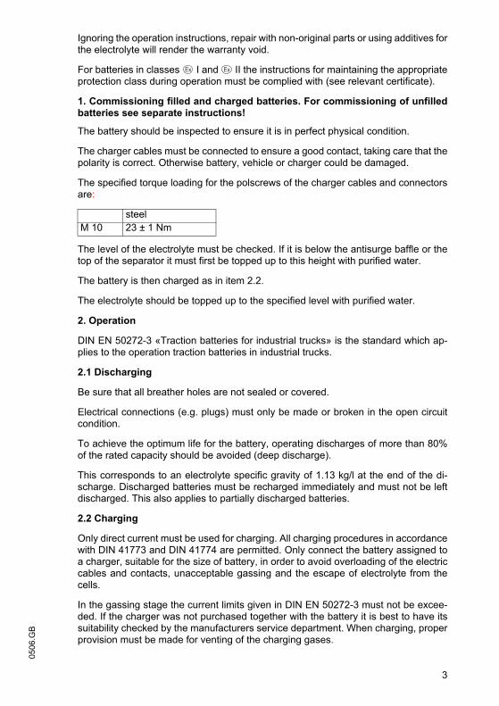
3
0506
.GBIgnoring the operation instructions, repair with non-original parts or using additives forthe electrolyte will render the warranty void.
For batteries in classes I and II the instructions for maintaining the appropriateprotection class during operation must be complied with (see relevant certificate).
1. Commissioning filled and charged batteries. For commissioning of unfilledbatteries see separate instructions!
The battery should be inspected to ensure it is in perfect physical condition.
The charger cables must be connected to ensure a good contact, taking care that thepolarity is correct. Otherwise battery, vehicle or charger could be damaged.
The specified torque loading for the polscrews of the charger cables and connectorsare:
The level of the electrolyte must be checked. If it is below the antisurge baffle or thetop of the separator it must first be topped up to this height with purified water.
The battery is then charged as in item 2.2.
The electrolyte should be topped up to the specified level with purified water.
2. Operation
DIN EN 50272-3 «Traction batteries for industrial trucks» is the standard which ap-plies to the operation traction batteries in industrial trucks.
2.1 Discharging
Be sure that all breather holes are not sealed or covered.
Electrical connections (e.g. plugs) must only be made or broken in the open circuitcondition.
To achieve the optimum life for the battery, operating discharges of more than 80%of the rated capacity should be avoided (deep discharge).
This corresponds to an electrolyte specific gravity of 1.13 kg/l at the end of the di-scharge. Discharged batteries must be recharged immediately and must not be leftdischarged. This also applies to partially discharged batteries.
2.2 Charging
Only direct current must be used for charging. All charging procedures in accordancewith DIN 41773 and DIN 41774 are permitted. Only connect the battery assigned toa charger, suitable for the size of battery, in order to avoid overloading of the electriccables and contacts, unacceptable gassing and the escape of electrolyte from thecells.
In the gassing stage the current limits given in DIN EN 50272-3 must not be excee-ded. If the charger was not purchased together with the battery it is best to have itssuitability checked by the manufacturers service department. When charging, properprovision must be made for venting of the charging gases.
steel M 10 23 ± 1 Nm
3
0506
.GB
Ignoring the operation instructions, repair with non-original parts or using additives forthe electrolyte will render the warranty void.
For batteries in classes I and II the instructions for maintaining the appropriateprotection class during operation must be complied with (see relevant certificate).
1. Commissioning filled and charged batteries. For commissioning of unfilledbatteries see separate instructions!
The battery should be inspected to ensure it is in perfect physical condition.
The charger cables must be connected to ensure a good contact, taking care that thepolarity is correct. Otherwise battery, vehicle or charger could be damaged.
The specified torque loading for the polscrews of the charger cables and connectorsare:
The level of the electrolyte must be checked. If it is below the antisurge baffle or thetop of the separator it must first be topped up to this height with purified water.
The battery is then charged as in item 2.2.
The electrolyte should be topped up to the specified level with purified water.
2. Operation
DIN EN 50272-3 «Traction batteries for industrial trucks» is the standard which ap-plies to the operation traction batteries in industrial trucks.
2.1 Discharging
Be sure that all breather holes are not sealed or covered.
Electrical connections (e.g. plugs) must only be made or broken in the open circuitcondition.
To achieve the optimum life for the battery, operating discharges of more than 80%of the rated capacity should be avoided (deep discharge).
This corresponds to an electrolyte specific gravity of 1.13 kg/l at the end of the di-scharge. Discharged batteries must be recharged immediately and must not be leftdischarged. This also applies to partially discharged batteries.
2.2 Charging
Only direct current must be used for charging. All charging procedures in accordancewith DIN 41773 and DIN 41774 are permitted. Only connect the battery assigned toa charger, suitable for the size of battery, in order to avoid overloading of the electriccables and contacts, unacceptable gassing and the escape of electrolyte from thecells.
In the gassing stage the current limits given in DIN EN 50272-3 must not be excee-ded. If the charger was not purchased together with the battery it is best to have itssuitability checked by the manufacturers service department. When charging, properprovision must be made for venting of the charging gases.
steel M 10 23 ± 1 Nm
0506
.GB
4
Battery container lids and the covers of battery compartments must be opened or re-moved. The vent plugs should stay on the cells and remain closed.
With the charger switched off connect up the battery, ensuring that the polarity is cor-rect. (positive to positive, negative to negative). Now switch on the charger. Whencharging the temperature of the electrolyte rises by about 10°C, so charging shouldonly begin if the electrolyte temperature is below 45°C. The electrolyte temperatureof batteries should be at least +10°C before charging otherwise a full charge will notbe achieved.
A charge is finished when the specific gravity of the electrolyte and the battery voltagehave remained constant for two hours. Special instructions for the operation of batte-ries in hazardous areas. This concerns batteries which are used in accordance withEN 50014, DIN VDE 0170/0171 Ex (in areas with a firedamp hazard) or Ex II (in po-tentially explosive areas). During charging and subsequent gassing the container lidsmust be removed or opened so that the explosive mixture of gases loses its flamma-bility due to adequate ventilation. The containers for batteries with plate protectionpacks must not be closed until at least half an hour after charging has past.
2.3 Equalising charge
Equalising charges are used to safeguard the life of the battery and to maintain itscapacity. They are necessary after deep discharges, repeated incomplete rechargesand charges to an IU characteristic curve. Equalising charges are carried out follo-wing normal charging. The charging current must not exceed 5 A/100 Ah of rated ca-pacity (end of charge - see point 2.2).
Watch the temperature!
2.4 Temperature
An electrolyte temperature of 30°C is specified as the rated temperature. Higher tem-peratures shorten the life of the battery, lower temperatures reduce the capacity avai-lable. 55°C is the upper temperature limit and is not acceptable as an operating tem-perature.
2.5 Electrolyte
The rated specific gravity (S. G.) of the electrolyte is related to a temperature of 30°Cand the nominal electrolyte level in the cell in fully charged condition. Higher tempe-ratures reduce the specified gravity of the electrolyte, lower temperatures increase it.The temperature correction factor is -0.0007 kg/l per °C, e.g. an electrolyte specificgravity of 1.28 kg/l at 45°C corresponds to an S.G. of 1.29 kg/l at 30°C.
The electrolyte must conform to the purity regulations in DIN 43530 part 2.
5
0506
.GB3. Maintenance
3.1 Daily
Charge the battery after every discharge. Towards the end of charge the electrolytelevel should be checked and if necessary topped up to the specified level with purifiedwater. The electrolyte level must not fall below the anti-surge baffle or the top of theseparator or the electrolyte „min“ level mark.
3.2 Weekly
Visual inspection after recharging for signs of dirt and mechanical damage. If the bat-tery is charged regularly with a IU characteristic curve an equalising charge must becarried out (see point 2.3).
3.3 Monthly
At the end of the charge the voltages of all cells or bloc batteries should be measuredwith the charger switched on, and recorded. After charging has ended the specificgravity and the temperature of the electrolyte in all cells should be measured and re-corded.
If significant changes from earlier measurements or differences between the cells orbloc batteries are found further testing and maintenance by the service departmentshould be requested.
3.4 Annually
In accordance with DIN VDE 0117 at least once per year, the insulation resistance ofthe truck and the battery must be checked by an electrical specialist.
The tests on the insulation resistance of the battery must be conducted in accordancewith DIN EN 60254-1.
The insulation resistance of the battery thus determined must not be below a value of50 Ω per Volt of nominal voltage, in compliance with DIN EN 50272-3.
For batteries up to 20 V nominal voltage the minimum value is 1000 Ω.
4. Care of the battery
The battery should always be kept clean and dry to prevent tracking currents. Clea-ning must be done in accordance with the ZVEI code of practice «The Cleaning ofVehicle Traction batteries».
Any liquid in the battery tray must be extracted and disposed of in the prescribed man-ner. Damage to the insulation of the tray should be repaired after cleaning, to ensurethat the insulation value complies DIN EN 50272-3 and to prevent tray corrosion. If itis necessary to remove cells it is best to call in our service department for this.
5
0506
.GB
3. Maintenance
3.1 Daily
Charge the battery after every discharge. Towards the end of charge the electrolytelevel should be checked and if necessary topped up to the specified level with purifiedwater. The electrolyte level must not fall below the anti-surge baffle or the top of theseparator or the electrolyte „min“ level mark.
3.2 Weekly
Visual inspection after recharging for signs of dirt and mechanical damage. If the bat-tery is charged regularly with a IU characteristic curve an equalising charge must becarried out (see point 2.3).
3.3 Monthly
At the end of the charge the voltages of all cells or bloc batteries should be measuredwith the charger switched on, and recorded. After charging has ended the specificgravity and the temperature of the electrolyte in all cells should be measured and re-corded.
If significant changes from earlier measurements or differences between the cells orbloc batteries are found further testing and maintenance by the service departmentshould be requested.
3.4 Annually
In accordance with DIN VDE 0117 at least once per year, the insulation resistance ofthe truck and the battery must be checked by an electrical specialist.
The tests on the insulation resistance of the battery must be conducted in accordancewith DIN EN 60254-1.
The insulation resistance of the battery thus determined must not be below a value of50 Ω per Volt of nominal voltage, in compliance with DIN EN 50272-3.
For batteries up to 20 V nominal voltage the minimum value is 1000 Ω.
4. Care of the battery
The battery should always be kept clean and dry to prevent tracking currents. Clea-ning must be done in accordance with the ZVEI code of practice «The Cleaning ofVehicle Traction batteries».
Any liquid in the battery tray must be extracted and disposed of in the prescribed man-ner. Damage to the insulation of the tray should be repaired after cleaning, to ensurethat the insulation value complies DIN EN 50272-3 and to prevent tray corrosion. If itis necessary to remove cells it is best to call in our service department for this.
0506
.GB
6
5. Storage
If batteries are taken out of service for a lengthy period they should be stored in thefully charged condition in a dry, frost-free room. To ensure the battery is always readyfor use a choice of charging methods can be made:
1. a monthly equalising charge as in point 2.3
2. float charging at a charging voltage of 2.23 V x the number of cells. The storagetime should be taken into account when considering the life of the battery.
6. Malfunctions
If malfunctions are found on the battery or the charger our service department shouldbe called in without delay. The measurements taken in point 3.3 will facilitate fault fin-ding and their elimination.
A service contract with us will make it easier to detect and correct faults in good time.
Back to the manufacturer!
Batteries with this sign must be recycled.
Batteries which are not returned for the recycling process must bedisposed of as hazardous waste!
We reserve the right make technical modification.
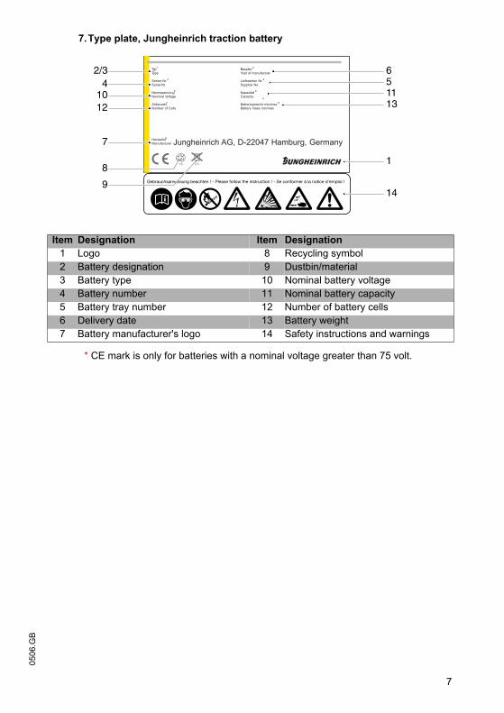
7
0506
.GB7.Type plate, Jungheinrich traction battery
* CE mark is only for batteries with a nominal voltage greater than 75 volt.
Item Designation Item Designation1 Logo 8 Recycling symbol2 Battery designation 9 Dustbin/material3 Battery type 10 Nominal battery voltage4 Battery number 11 Nominal battery capacity5 Battery tray number 12 Number of battery cells6 Delivery date 13 Battery weight7 Battery manufacturer's logo 14 Safety instructions and warnings
Typ1
Type
Nennspannung5
Nominal Voltage
Hersteller9
Manufacturer
Kapazität 6
Capacity
Zellenzahl7
Number of CellsBatteriegewicht min/max 8
Battery mass min/max
Serien-Nr.3
Serial-Nr.Lieferanten Nr. 4
Supplier No.
Baujahr 2
Year of manufacture
Jungheinrich AG, D-22047 Hamburg, Germany
5
Pb Pb
2/3 651113
1
14
41012
7
8
9
7
0506
.GB
7.Type plate, Jungheinrich traction battery
* CE mark is only for batteries with a nominal voltage greater than 75 volt.
Item Designation Item Designation1 Logo 8 Recycling symbol2 Battery designation 9 Dustbin/material3 Battery type 10 Nominal battery voltage4 Battery number 11 Nominal battery capacity5 Battery tray number 12 Number of battery cells6 Delivery date 13 Battery weight7 Battery manufacturer's logo 14 Safety instructions and warnings
Typ1
Type
Nennspannung5
Nominal Voltage
Hersteller9
Manufacturer
Kapazität 6
Capacity
Zellenzahl7
Number of CellsBatteriegewicht min/max 8
Battery mass min/max
Serien-Nr.3
Serial-Nr.Lieferanten Nr. 4
Supplier No.
Baujahr 2
Year of manufacture
Jungheinrich AG, D-22047 Hamburg, Germany
5
Pb Pb
2/3 651113
1
14
41012
7
8
9
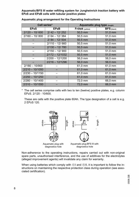
0506
.GB
8
Aquamatic/BFS III water refilling system for Jungheinrich traction battery withEPzS and EPzB cells with tubular positive plates
Aquamatic plug arrangement for the Operating Instructions
* The cell series comprise cells with two to ten (twelve) positive plates, e.g. columnEPzS. 2/120 - 10/600.
These are cells with the positive plate 60Ah. The type designation of a cell is e.g.2 EPzS 120.
Non-adherence to the operating instructions, repairs carried out with non-originalspare parts, unauthorised interference, and the use of additives for the electrolytes(alleged improvement agents) will invalidate any claim for warranty.
When using batteries which comply with I and II, it is important to follow the in-structions on maintaining the respective protection class during operation (see asso-ciated certification).
Cell series* Aquamatic plug type (length)
EPzS EPzB Frötek (yellow) BFS (black)
2/120 – 10/ 600 2/ 42 – 12/ 252 50,5 mm 51,0 mm2/160 – 10/ 800 2/ 64 – 12/ 384 50,5 mm 51,0 mm
– 2/ 84 – 12/ 504 50,5 mm 51,0 mm– 2/110 – 12/ 660 50,5 mm 51,0 mm– 2/130 – 12/ 780 50,5 mm 51,0 mm– 2/150 – 12/ 900 50,5 mm 51,0 mm– 2/172 – 12/1032 50,5 mm 51,0 mm– 2/200 – 12/1200 56,0 mm 56,0 mm– 2/216 – 12/1296 56,0 mm 56,0 mm
2/180 – 10/900 – 61,0 mm 61,0 mm2/210 – 10/1050 – 61,0 mm 61,0 mm2/230 – 10/1150 – 61,0 mm 61,0 mm2/250 – 10/1250 – 61,0 mm 61,0 mm2/280 – 10/1400 – 72,0 mm 66,0 mm2/310 – 10/1550 – 72,0 mm 66,0 mm
stro
ke
leng
th
stro
ke
leng
th
Aquamatic plug with diagnostics hole
Aquamatic plug BFS III with diagnostics hole
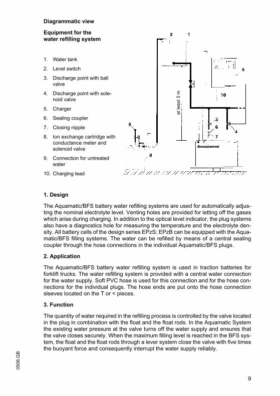
9
0506
.GBDiagrammatic view
Equipment for the water refilling system
1. Water tank
2. Level switch
3. Discharge point with ball valve
4. Discharge point with sole-noid valve
5. Charger
6. Sealing coupler
7. Closing nipple
8. Ion exchange cartridge with conductance meter and solenoid valve
9. Connection for untreated water
10. Charging lead
1. Design
The Aquamatic/BFS battery water refilling systems are used for automatically adjus-ting the nominal electrolyte level. Venting holes are provided for letting off the gaseswhich arise during charging. In addition to the optical level indicator, the plug systemsalso have a diagnostics hole for measuring the temperature and the electrolyte den-sity. All battery cells of the design series EPzS; EPzB can be equipped with the Aqua-matic/BFS filling systems. The water can be refilled by means of a central sealingcoupler through the hose connections in the individual Aquamatic/BFS plugs.
2. Application
The Aquamatic/BFS battery water refilling system is used in traction batteries forforklift trucks. The water refilling system is provided with a central water connectionfor the water supply. Soft PVC hose is used for this connection and for the hose con-nections for the individual plugs. The hose ends are put onto the hose connectionsleeves located on the T or < pieces.
3. Function
The quantity of water required in the refilling process is controlled by the valve locatedin the plug in combination with the float and the float rods. In the Aquamatic Systemthe existing water pressure at the valve turns off the water supply and ensures thatthe valve closes securely. When the maximum filling level is reached in the BFS sys-tem, the float and the float rods through a lever system close the valve with five timesthe buoyant force and consequently interrupt the water supply reliably.
at le
ast 3
m
9
0506
.GB
Diagrammatic view
Equipment for the water refilling system
1. Water tank
2. Level switch
3. Discharge point with ball valve
4. Discharge point with sole-noid valve
5. Charger
6. Sealing coupler
7. Closing nipple
8. Ion exchange cartridge with conductance meter and solenoid valve
9. Connection for untreated water
10. Charging lead
1. Design
The Aquamatic/BFS battery water refilling systems are used for automatically adjus-ting the nominal electrolyte level. Venting holes are provided for letting off the gaseswhich arise during charging. In addition to the optical level indicator, the plug systemsalso have a diagnostics hole for measuring the temperature and the electrolyte den-sity. All battery cells of the design series EPzS; EPzB can be equipped with the Aqua-matic/BFS filling systems. The water can be refilled by means of a central sealingcoupler through the hose connections in the individual Aquamatic/BFS plugs.
2. Application
The Aquamatic/BFS battery water refilling system is used in traction batteries forforklift trucks. The water refilling system is provided with a central water connectionfor the water supply. Soft PVC hose is used for this connection and for the hose con-nections for the individual plugs. The hose ends are put onto the hose connectionsleeves located on the T or < pieces.
3. Function
The quantity of water required in the refilling process is controlled by the valve locatedin the plug in combination with the float and the float rods. In the Aquamatic Systemthe existing water pressure at the valve turns off the water supply and ensures thatthe valve closes securely. When the maximum filling level is reached in the BFS sys-tem, the float and the float rods through a lever system close the valve with five timesthe buoyant force and consequently interrupt the water supply reliably.
at le
ast 3
m
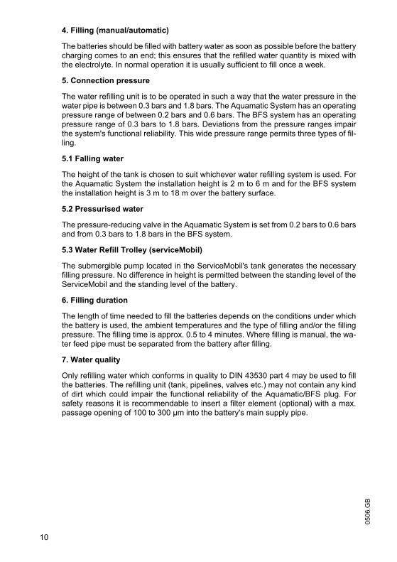
0506
.GB
10
4. Filling (manual/automatic)
The batteries should be filled with battery water as soon as possible before the batterycharging comes to an end; this ensures that the refilled water quantity is mixed withthe electrolyte. In normal operation it is usually sufficient to fill once a week.
5. Connection pressure
The water refilling unit is to be operated in such a way that the water pressure in thewater pipe is between 0.3 bars and 1.8 bars. The Aquamatic System has an operatingpressure range of between 0.2 bars and 0.6 bars. The BFS system has an operatingpressure range of 0.3 bars to 1.8 bars. Deviations from the pressure ranges impairthe system's functional reliability. This wide pressure range permits three types of fil-ling.
5.1 Falling water
The height of the tank is chosen to suit whichever water refilling system is used. Forthe Aquamatic System the installation height is 2 m to 6 m and for the BFS systemthe installation height is 3 m to 18 m over the battery surface.
5.2 Pressurised water
The pressure-reducing valve in the Aquamatic System is set from 0.2 bars to 0.6 barsand from 0.3 bars to 1.8 bars in the BFS system.
5.3 Water Refill Trolley (serviceMobil)
The submergible pump located in the ServiceMobil's tank generates the necessaryfilling pressure. No difference in height is permitted between the standing level of theServiceMobil and the standing level of the battery.
6. Filling duration
The length of time needed to fill the batteries depends on the conditions under whichthe battery is used, the ambient temperatures and the type of filling and/or the fillingpressure. The filling time is approx. 0.5 to 4 minutes. Where filling is manual, the wa-ter feed pipe must be separated from the battery after filling.
7. Water quality
Only refilling water which conforms in quality to DIN 43530 part 4 may be used to fillthe batteries. The refilling unit (tank, pipelines, valves etc.) may not contain any kindof dirt which could impair the functional reliability of the Aquamatic/BFS plug. Forsafety reasons it is recommendable to insert a filter element (optional) with a max.passage opening of 100 to 300 µm into the battery's main supply pipe.
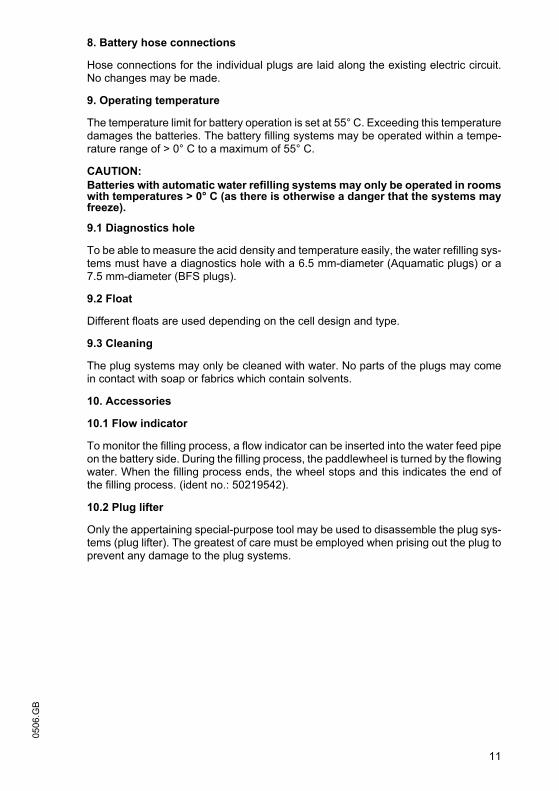
11
0506
.GB8. Battery hose connections
Hose connections for the individual plugs are laid along the existing electric circuit.No changes may be made.
9. Operating temperature
The temperature limit for battery operation is set at 55° C. Exceeding this temperaturedamages the batteries. The battery filling systems may be operated within a tempe-rature range of > 0° C to a maximum of 55° C.
CAUTION:Batteries with automatic water refilling systems may only be operated in roomswith temperatures > 0° C (as there is otherwise a danger that the systems mayfreeze).
9.1 Diagnostics hole
To be able to measure the acid density and temperature easily, the water refilling sys-tems must have a diagnostics hole with a 6.5 mm-diameter (Aquamatic plugs) or a7.5 mm-diameter (BFS plugs).
9.2 Float
Different floats are used depending on the cell design and type.
9.3 Cleaning
The plug systems may only be cleaned with water. No parts of the plugs may comein contact with soap or fabrics which contain solvents.
10. Accessories
10.1 Flow indicator
To monitor the filling process, a flow indicator can be inserted into the water feed pipeon the battery side. During the filling process, the paddlewheel is turned by the flowingwater. When the filling process ends, the wheel stops and this indicates the end ofthe filling process. (ident no.: 50219542).
10.2 Plug lifter
Only the appertaining special-purpose tool may be used to disassemble the plug sys-tems (plug lifter). The greatest of care must be employed when prising out the plug toprevent any damage to the plug systems.
11
0506
.GB
8. Battery hose connections
Hose connections for the individual plugs are laid along the existing electric circuit.No changes may be made.
9. Operating temperature
The temperature limit for battery operation is set at 55° C. Exceeding this temperaturedamages the batteries. The battery filling systems may be operated within a tempe-rature range of > 0° C to a maximum of 55° C.
CAUTION:Batteries with automatic water refilling systems may only be operated in roomswith temperatures > 0° C (as there is otherwise a danger that the systems mayfreeze).
9.1 Diagnostics hole
To be able to measure the acid density and temperature easily, the water refilling sys-tems must have a diagnostics hole with a 6.5 mm-diameter (Aquamatic plugs) or a7.5 mm-diameter (BFS plugs).
9.2 Float
Different floats are used depending on the cell design and type.
9.3 Cleaning
The plug systems may only be cleaned with water. No parts of the plugs may comein contact with soap or fabrics which contain solvents.
10. Accessories
10.1 Flow indicator
To monitor the filling process, a flow indicator can be inserted into the water feed pipeon the battery side. During the filling process, the paddlewheel is turned by the flowingwater. When the filling process ends, the wheel stops and this indicates the end ofthe filling process. (ident no.: 50219542).
10.2 Plug lifter
Only the appertaining special-purpose tool may be used to disassemble the plug sys-tems (plug lifter). The greatest of care must be employed when prising out the plug toprevent any damage to the plug systems.
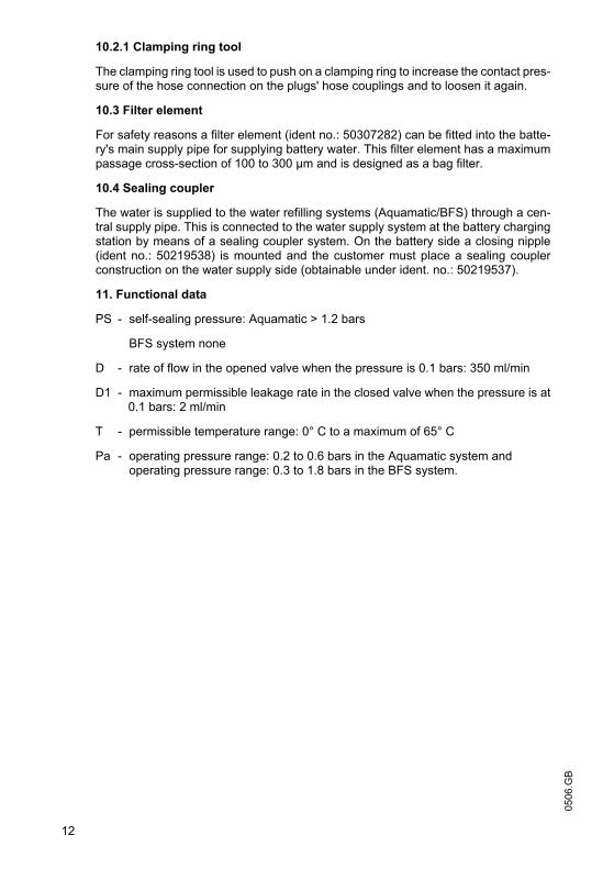
0506
.GB
12
10.2.1 Clamping ring tool
The clamping ring tool is used to push on a clamping ring to increase the contact pres-sure of the hose connection on the plugs' hose couplings and to loosen it again.
10.3 Filter element
For safety reasons a filter element (ident no.: 50307282) can be fitted into the batte-ry's main supply pipe for supplying battery water. This filter element has a maximumpassage cross-section of 100 to 300 µm and is designed as a bag filter.
10.4 Sealing coupler
The water is supplied to the water refilling systems (Aquamatic/BFS) through a cen-tral supply pipe. This is connected to the water supply system at the battery chargingstation by means of a sealing coupler system. On the battery side a closing nipple(ident no.: 50219538) is mounted and the customer must place a sealing couplerconstruction on the water supply side (obtainable under ident. no.: 50219537).
11. Functional data
PS - self-sealing pressure: Aquamatic > 1.2 bars
BFS system none
D - rate of flow in the opened valve when the pressure is 0.1 bars: 350 ml/min
D1 - maximum permissible leakage rate in the closed valve when the pressure is at0.1 bars: 2 ml/min
T - permissible temperature range: 0° C to a maximum of 65° C
Pa - operating pressure range: 0.2 to 0.6 bars in the Aquamatic system andoperating pressure range: 0.3 to 1.8 bars in the BFS system.
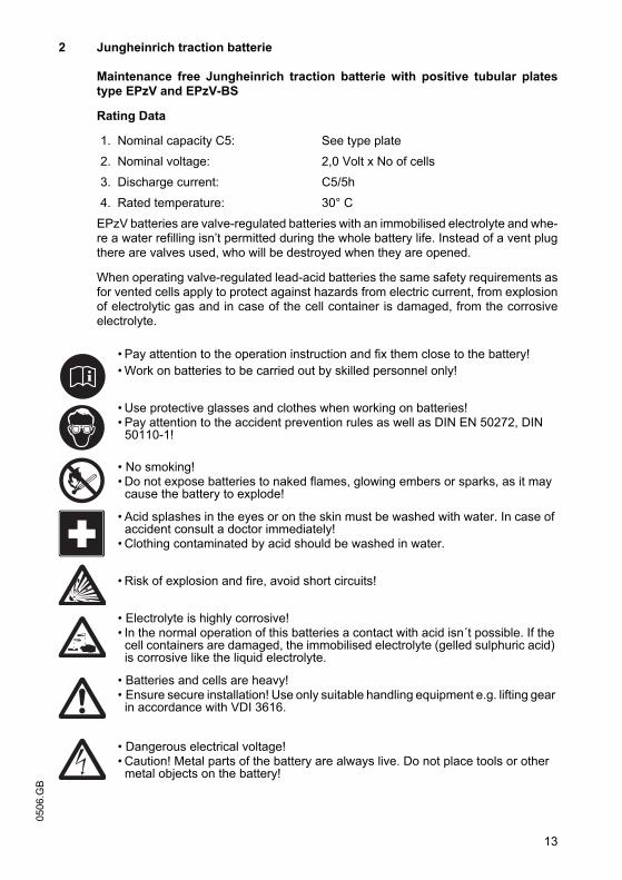
13
0506
.GB
2 Jungheinrich traction batterie
Maintenance free Jungheinrich traction batterie with positive tubular platestype EPzV and EPzV-BS
Rating Data
1. Nominal capacity C5: See type plate
2. Nominal voltage: 2,0 Volt x No of cells
3. Discharge current: C5/5h
4. Rated temperature: 30° C
EPzV batteries are valve-regulated batteries with an immobilised electrolyte and whe-re a water refilling isn’t permitted during the whole battery life. Instead of a vent plugthere are valves used, who will be destroyed when they are opened.
When operating valve-regulated lead-acid batteries the same safety requirements asfor vented cells apply to protect against hazards from electric current, from explosionof electrolytic gas and in case of the cell container is damaged, from the corrosiveelectrolyte.
• Pay attention to the operation instruction and fix them close to the battery!• Work on batteries to be carried out by skilled personnel only!
• Use protective glasses and clothes when working on batteries!• Pay attention to the accident prevention rules as well as DIN EN 50272, DIN
50110-1!
• No smoking!• Do not expose batteries to naked flames, glowing embers or sparks, as it may
cause the battery to explode!
• Acid splashes in the eyes or on the skin must be washed with water. In case of accident consult a doctor immediately!
• Clothing contaminated by acid should be washed in water.
• Risk of explosion and fire, avoid short circuits!
• Electrolyte is highly corrosive!• In the normal operation of this batteries a contact with acid isn´t possible. If the
cell containers are damaged, the immobilised electrolyte (gelled sulphuric acid) is corrosive like the liquid electrolyte.
• Batteries and cells are heavy!• Ensure secure installation! Use only suitable handling equipment e.g. lifting gear
in accordance with VDI 3616.
• Dangerous electrical voltage!• Caution! Metal parts of the battery are always live. Do not place tools or other
metal objects on the battery!
0506
.GB
14
Ignoring the operation instructions, repair with non-original parts and non authorisedinterventions will render the warranty void.
For batteries in classes I and II the instructions for maintaining the appropriateprotection class during operation must be complied with (see relevant certificate).
1. Commissioning
The battery should be inspected to ensure it is in perfect physical condition.
The battery end cables must have a good contact to terminals, check that the polarityis correct.
Otherwise battery, vehicle or charger could be destroyed.
The battery has to be charged according to item 2.2
The specified torque loading for the pole screws of the end cables and connectorsare:
2. Operation
DIN EN 50272-3 «Traction batteries for industrial trucks» is the standard which ap-plies to the operation traction batteries in industrial trucks.
2.1 Discharging
Ventilation openings must not be sealed or covered.
Electrical connections (e.g. plugs) must only be made or broken in the open circuitcondition.
To achieve the optimum life for the battery, operating discharges of more than 60%of the rated capacity should be avoided (deep discharge).
They reduce the battery life considerable. To measure the state of discharge use onlythe battery manufacturer recommended discharge indicators.
Discharged batteries must be recharged immediately and must not be left dischar-ged.
This also applies to partially discharged batteries.
2.2 Charging
Only direct current must be used for charging. Charging procedures according to DIN41773 and DIN 41774 must only be applied in the manufacturer approved modifica-tions. Therefore only battery manufacturer approved chargers must be used. Onlyconnect the battery assigned to a charger, suitable for the size of battery, in order toavoid overloading of the electric cables and contacts and unacceptable gassing of thecells. EPzV batteries have a low gas emission.
When charging, proper provision must be made for venting of the charging gases.Battery container lids and the covers of battery compartments must be opened or re-moved.
steel M 10 23 ± 1 Nm
0506
.GB
14
Ignoring the operation instructions, repair with non-original parts and non authorisedinterventions will render the warranty void.
For batteries in classes I and II the instructions for maintaining the appropriateprotection class during operation must be complied with (see relevant certificate).
1. Commissioning
The battery should be inspected to ensure it is in perfect physical condition.
The battery end cables must have a good contact to terminals, check that the polarityis correct.
Otherwise battery, vehicle or charger could be destroyed.
The battery has to be charged according to item 2.2
The specified torque loading for the pole screws of the end cables and connectorsare:
2. Operation
DIN EN 50272-3 «Traction batteries for industrial trucks» is the standard which ap-plies to the operation traction batteries in industrial trucks.
2.1 Discharging
Ventilation openings must not be sealed or covered.
Electrical connections (e.g. plugs) must only be made or broken in the open circuitcondition.
To achieve the optimum life for the battery, operating discharges of more than 60%of the rated capacity should be avoided (deep discharge).
They reduce the battery life considerable. To measure the state of discharge use onlythe battery manufacturer recommended discharge indicators.
Discharged batteries must be recharged immediately and must not be left dischar-ged.
This also applies to partially discharged batteries.
2.2 Charging
Only direct current must be used for charging. Charging procedures according to DIN41773 and DIN 41774 must only be applied in the manufacturer approved modifica-tions. Therefore only battery manufacturer approved chargers must be used. Onlyconnect the battery assigned to a charger, suitable for the size of battery, in order toavoid overloading of the electric cables and contacts and unacceptable gassing of thecells. EPzV batteries have a low gas emission.
When charging, proper provision must be made for venting of the charging gases.Battery container lids and the covers of battery compartments must be opened or re-moved.
steel M 10 23 ± 1 Nm
15
0506
.GBWith the charger switched off connect up the battery, ensuring that the polarity is cor-rect (positive to positive, negative to negative). Now switch on the charger. Whencharging the temperature of the battery rises by about 15° C, so charging should onlybegin if the battery temperature is below 35° C. The battery temperature should be atleast +15°C before charging otherwise a full charge will not be achieved. Are the tem-peratures a longer time higher than +40° C or lower than +15° C, so the chargersneed a temperatures regulated voltage.
The correction factor is, in accordance with DIN EN 50272-1, -0,005 V/c and Kelvin.
Special instructions for the operation of batteries in hazardous areas.
This concerns batteries which are used in accordance with EN 50 014, DIN VDE 0170/ 0171 Ex I (in areas with a firedamp hazard) or Ex II (in potentially explosive areas).The attention pictograms has to be respected.
2.3 Equalising charge
Equalising charges are used to safeguard the life of the battery and to maintain itscapacity. Equalising charges are carried out following normal charging.
They are necessary after deep discharges and repeated incomplete recharges. Forthe equalising charges has to be used only the battery manufacturer prescribed char-gers.
Watch the temperature!
2.4 Temperature
A battery temperature of 30°C is specified as the rated temperature. Higher tempera-tures shorten the life of the battery, lower temperatures reduce the available capacity.45° C is the upper temperature limit and is not acceptable as an operating tempera-ture.
2.5 Electrolyte
The electrolyte is immobilised in a gel. The density of the electrolyte can not bemeasured.
3. Maintenance
Don’t refill water!
3.1 Daily
Charge the battery immediately after every discharge.
15
0506
.GB
With the charger switched off connect up the battery, ensuring that the polarity is cor-rect (positive to positive, negative to negative). Now switch on the charger. Whencharging the temperature of the battery rises by about 15° C, so charging should onlybegin if the battery temperature is below 35° C. The battery temperature should be atleast +15°C before charging otherwise a full charge will not be achieved. Are the tem-peratures a longer time higher than +40° C or lower than +15° C, so the chargersneed a temperatures regulated voltage.
The correction factor is, in accordance with DIN EN 50272-1, -0,005 V/c and Kelvin.
Special instructions for the operation of batteries in hazardous areas.
This concerns batteries which are used in accordance with EN 50 014, DIN VDE 0170/ 0171 Ex I (in areas with a firedamp hazard) or Ex II (in potentially explosive areas).The attention pictograms has to be respected.
2.3 Equalising charge
Equalising charges are used to safeguard the life of the battery and to maintain itscapacity. Equalising charges are carried out following normal charging.
They are necessary after deep discharges and repeated incomplete recharges. Forthe equalising charges has to be used only the battery manufacturer prescribed char-gers.
Watch the temperature!
2.4 Temperature
A battery temperature of 30°C is specified as the rated temperature. Higher tempera-tures shorten the life of the battery, lower temperatures reduce the available capacity.45° C is the upper temperature limit and is not acceptable as an operating tempera-ture.
2.5 Electrolyte
The electrolyte is immobilised in a gel. The density of the electrolyte can not bemeasured.
3. Maintenance
Don’t refill water!
3.1 Daily
Charge the battery immediately after every discharge.
0506
.GB
16
3.2 Weekly
Visual inspection after recharging for signs of dirt and mechanical damage.
3.3 Quarterly
After the end of the charge and a rest time of 5 h following should be measured andrecorded:
• the voltages of the battery
• the voltages of every cells
If significant changes from earlier measurements or differences between the cells orbloc batteries are found, further testing and maintenance by the service departmentshould be requested.
3.4 Annually
In accordance with DIN VDE 0117 at least once per year, the insulation resistance ofthe truck and the battery must be checked by an electrical specialist.
The tests on the insulation resistance of the battery must be conducted in accordancewith DIN 43539-1.
The insulation resistance of the battery thus determined must not be below a value of50 Ω per Volt of nominal voltage, in compliance with DIN EN 50272-3.
For batteries up to 20 V nominal voltage the minimum value is 1000 Ω.
4. Care of the battery
The battery should always be kept clean and dry to prevent tracking currents. Clea-ning must be done in accordance with the ZVEI code of practice «The Cleaning ofVehicle Traction batteries».
Any liquid in the battery tray must be extracted and disposed of in the prescribed man-ner.
Damage to the insulation of the tray should be repaired after cleaning, to ensure thatthe insulation value complies with DIN EN 50272-3 and to prevent tray corrosion. If itis necessary to remove cells it is best to call our service department for this.
5. Storage
If batteries are taken out of service for a lengthy period they should be stored in thefully charged condition in a dry, frost-free room.
To ensure the battery is always ready for use a choice of charging methods can bemade:
1.a quarterly full charging like charge as in point 2.2. If any consumer is connectedwith, e.g. measure or controlling systems, it can be, that this charging is necessaryevery 14 days.
2. float charging at a charging voltage of 2.25 V x the number of cells.
The storage time should be taken into account when considering the life of the batte-ry.
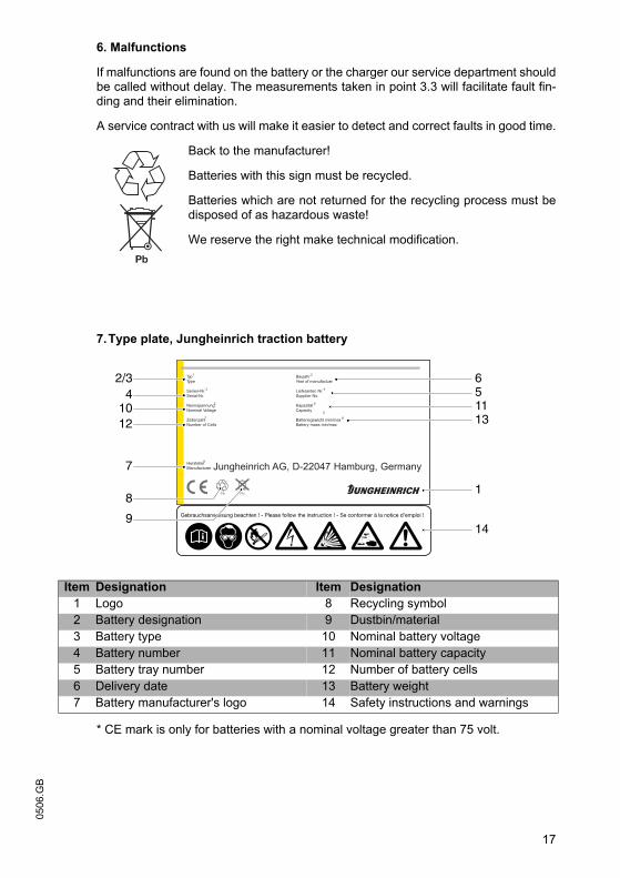
17
0506
.GB6. Malfunctions
If malfunctions are found on the battery or the charger our service department shouldbe called without delay. The measurements taken in point 3.3 will facilitate fault fin-ding and their elimination.
A service contract with us will make it easier to detect and correct faults in good time.
Back to the manufacturer!
Batteries with this sign must be recycled.
Batteries which are not returned for the recycling process must bedisposed of as hazardous waste!
We reserve the right make technical modification.
7.Type plate, Jungheinrich traction battery
* CE mark is only for batteries with a nominal voltage greater than 75 volt.
Item Designation Item Designation1 Logo 8 Recycling symbol2 Battery designation 9 Dustbin/material3 Battery type 10 Nominal battery voltage4 Battery number 11 Nominal battery capacity5 Battery tray number 12 Number of battery cells6 Delivery date 13 Battery weight7 Battery manufacturer's logo 14 Safety instructions and warnings
Typ1
Type
Nennspannung5
Nominal Voltage
Hersteller9
Manufacturer
Kapazität 6
Capacity
Zellenzahl7
Number of CellsBatteriegewicht min/max 8
Battery mass min/max
Serien-Nr.3
Serial-Nr.Lieferanten Nr. 4
Supplier No.
Baujahr 2
Year of manufacture
Jungheinrich AG, D-22047 Hamburg, Germany
5
Pb Pb
2/3 651113
1
14
41012
7
8
9
17
0506
.GB
6. Malfunctions
If malfunctions are found on the battery or the charger our service department shouldbe called without delay. The measurements taken in point 3.3 will facilitate fault fin-ding and their elimination.
A service contract with us will make it easier to detect and correct faults in good time.
Back to the manufacturer!
Batteries with this sign must be recycled.
Batteries which are not returned for the recycling process must bedisposed of as hazardous waste!
We reserve the right make technical modification.
7.Type plate, Jungheinrich traction battery
* CE mark is only for batteries with a nominal voltage greater than 75 volt.
Item Designation Item Designation1 Logo 8 Recycling symbol2 Battery designation 9 Dustbin/material3 Battery type 10 Nominal battery voltage4 Battery number 11 Nominal battery capacity5 Battery tray number 12 Number of battery cells6 Delivery date 13 Battery weight7 Battery manufacturer's logo 14 Safety instructions and warnings
Typ1
Type
Nennspannung5
Nominal Voltage
Hersteller9
Manufacturer
Kapazität 6
Capacity
Zellenzahl7
Number of CellsBatteriegewicht min/max 8
Battery mass min/max
Serien-Nr.3
Serial-Nr.Lieferanten Nr. 4
Supplier No.
Baujahr 2
Year of manufacture
Jungheinrich AG, D-22047 Hamburg, Germany
5
Pb Pb
2/3 651113
1
14
41012
7
8
9

0506
.GB
18
0506
.GB
18