Embed Size (px)
Citation preview
EGR 2201 Unit 7Operational Amplifiers
Read Alexander & Sadiku, Chapter 5. Homework #7 and Lab #7 due next
week. Quiz next week.
The Big Picture
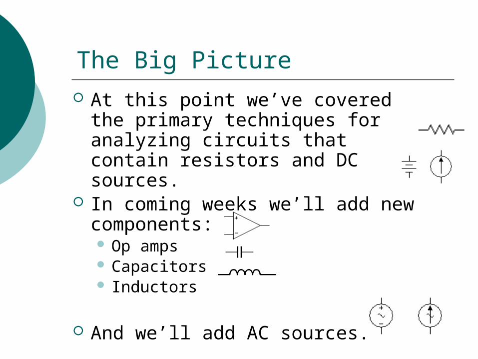
At this point we’ve covered the primary techniques for analyzing circuits that contain resistors and DC sources.
In coming weeks we’ll add new components: Op amps Capacitors Inductors
And we’ll add AC sources.
Operational Amplifier
An operational amplifier (or op amp) is a type of active element that behaves like a voltage-controlled voltage source.
Op amps were developed in the 1950s and 1960s. Originally they were used in analog
computers to perform mathematical operations such as addition, subtraction, differentiation, and integration.
Since then, many other uses have been found for op amps. Today they are one of the most widely used electronic elements.
The 741 Operational Amplifier
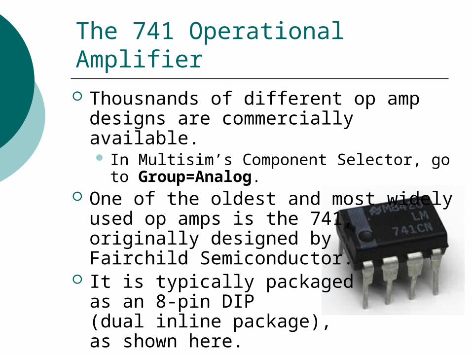
Thousnands of different op amp designs are commercially available. In Multisim’s Component Selector, go to
Group=Analog. One of the oldest and most widely used
op amps is the 741, originally designed by Fairchild Semiconductor.
It is typically packaged as an 8-pin DIP (dual inline package), as shown here.
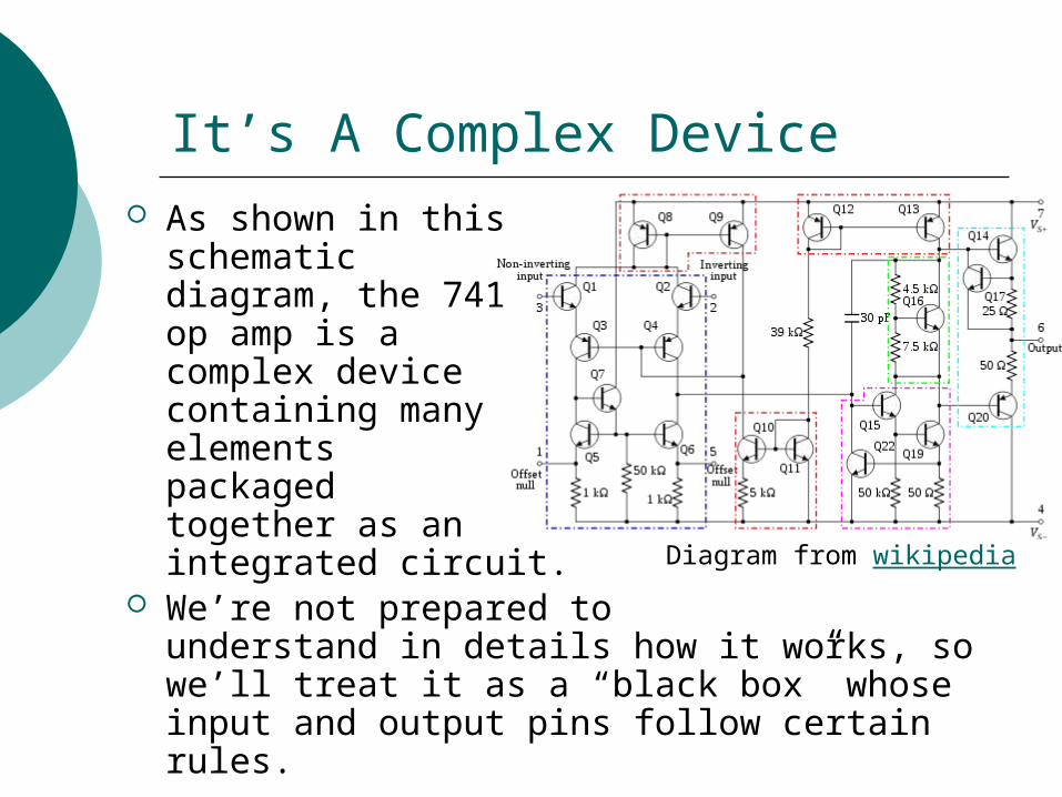
It’s A Complex Device As shown in this
schematic diagram, the 741 op amp is a complex devicecontaining many elements packaged together as an integrated circuit.
We’re not prepared to understand in details how it works, so we’ll treat it as a “black box” whose input and output pins follow certain rules.
Diagram from wikipedia
Pin Diagram and Schematic Symbol for the 741 Op Amp
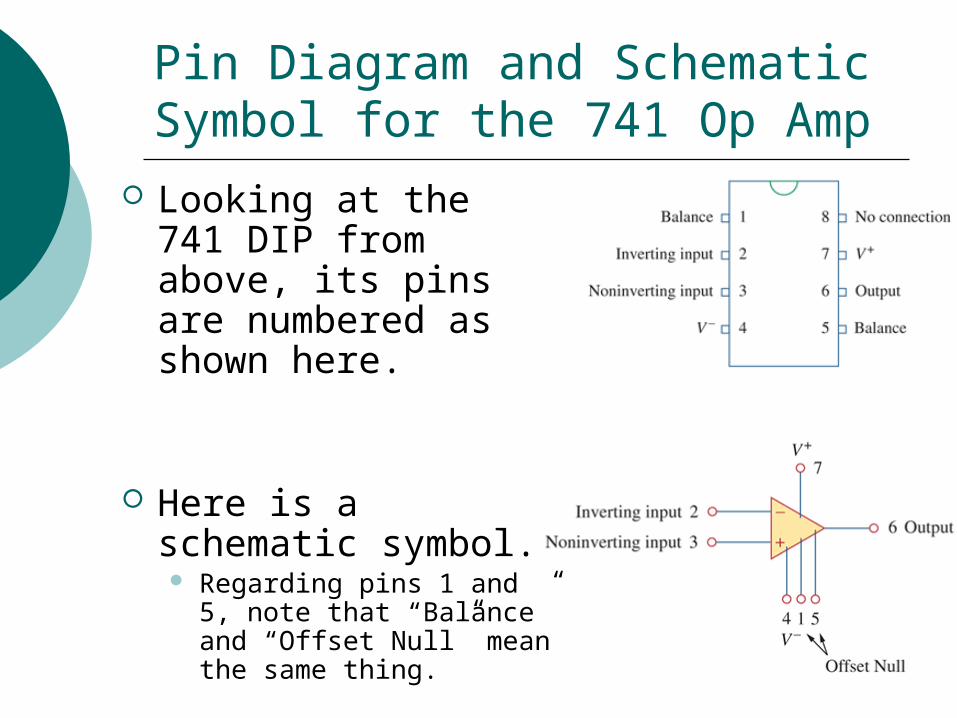
Looking at the 741 DIP from above, its pins are numbered as shown here.
Here is a schematic symbol. Regarding pins 1 and 5,
note that “Balance” and “Offset Null” mean the same thing.
Powering the 741 Op Amp
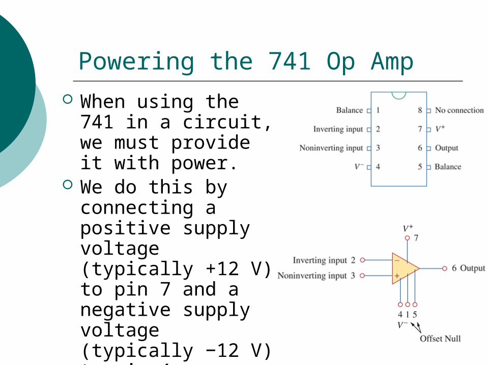
When using the 741 in a circuit, we must provide it with power.
We do this by connecting a positive supply voltage (typically +12 V) to pin 7 and a negative supply voltage (typically −12 V) to pin 4.
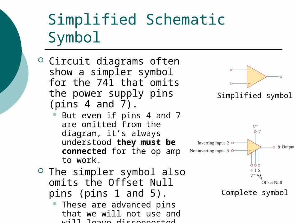
Simplified Schematic Symbol Circuit diagrams often show
a simpler symbol for the 741 that omits the power supply pins (pins 4 and 7). But even if pins 4 and 7 are
omitted from the diagram, it’s always understood they must be connected for the op amp to work.
The simpler symbol also omits the Offset Null pins (pins 1 and 5). These are advanced pins that
we will not use and will leave disconnected.
Complete symbol
Simplified symbol
Pay Attention to Which Input Is Which
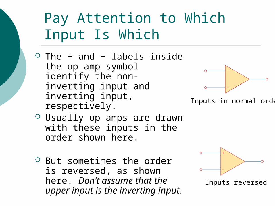
The + and − labels inside the op amp symbol identify the non-inverting input and inverting input, respectively.
Usually op amps are drawn with these inputs in the order shown here.
But sometimes the order is reversed, as shown here. Don’t assume that the upper input is the inverting input.
Inputs reversed
Inputs in normal order
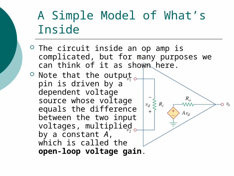
A Simple Model of What’s Inside The circuit inside an op amp is complicated,
but for many purposes we can think of it as shown here.
Note that the outputpin is driven by a dependent voltage source whose voltageequals the differencebetween the two input voltages, multipliedby a constant A, which is called the open-loop voltage gain.
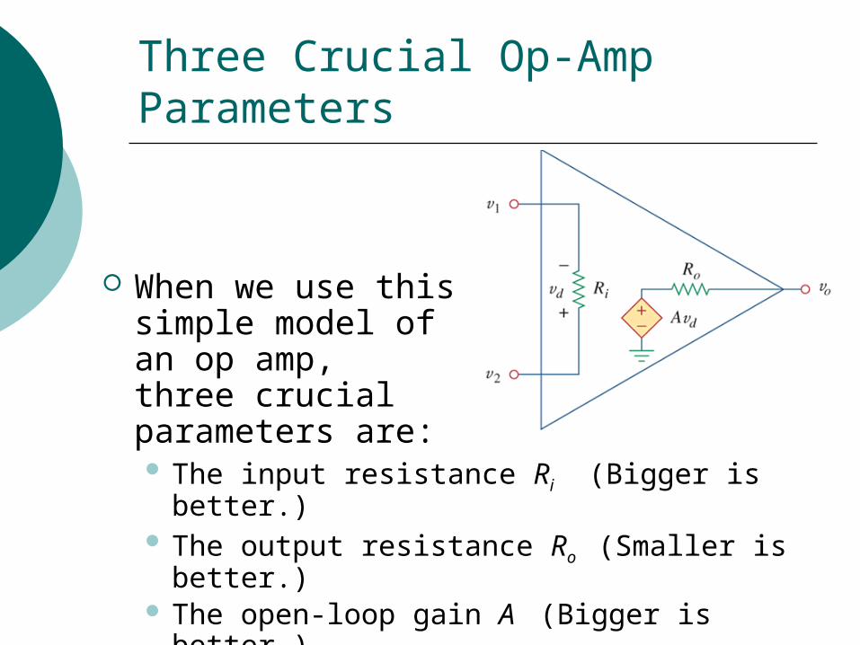
Three Crucial Op-Amp Parameters
When we use this simple model ofan op amp, three crucialparameters are: The input resistance Ri (Bigger is better.) The output resistance Ro (Smaller is better.) The open-loop gain A (Bigger is better.)
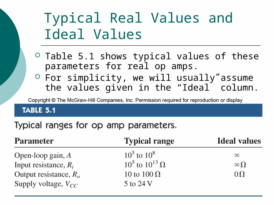
Typical Real Values and Ideal Values
Table 5.1 shows typical values of these parameters for real op amps.
For simplicity, we will usually assume the values given in the “Ideal” column.
Too Much of a Good Thing?
Having an extremely high (or infinite) voltage gain may seem like a good thing for an amplifier—and it is!
But in practical circuits, we generally want a much smaller voltage gain—maybe 20 or 50.
Therefore we usually connect other elements to the op amp. The purpose of these other elements is to reduce the circuit’s overall gain.
Negative Feedback
In general, negative feedback means connecting a circuit’s output back to its input in such a way that the output voltage is reduced.
In the case of an op amp, negative feedback means connecting the op amp’s output directly or indirectly to its inverting input.
(For positive feedback, which we won’t use, you would connected the output to the non-inverting input.)
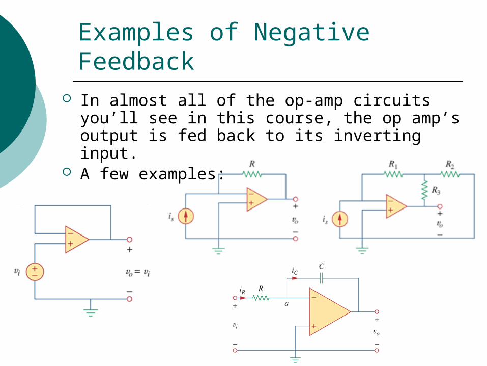
Examples of Negative Feedback In almost all of the op-amp circuits you’ll see in
this course, the op amp’s output is fed back to its inverting input.
A few examples:
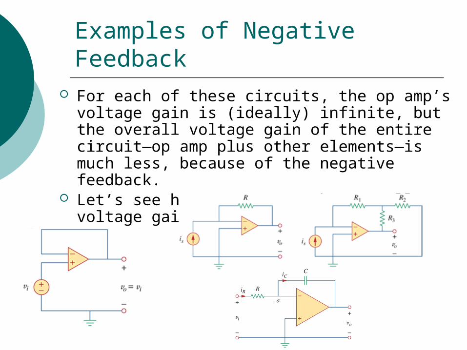
Examples of Negative Feedback For each of these circuits, the op amp’s voltage
gain is (ideally) infinite, but the overall voltage gain of the entire circuit—op amp plus other elements—is much less, because of the negative feedback.
Let’s see how to compute the overall voltage gain.
The Two “Golden Rules” of Op Amps
To analyze circuits like the ones on the previous slide, we’ll rely on two simple properties of an ideal op amp with negative feedback:1. The current into each input terminal
is zero.2. The voltage across the input
terminals is equal to zero. Horowitz and Hill, in their classic book
The Art of Electronics, call these the “golden rules” of op amps.
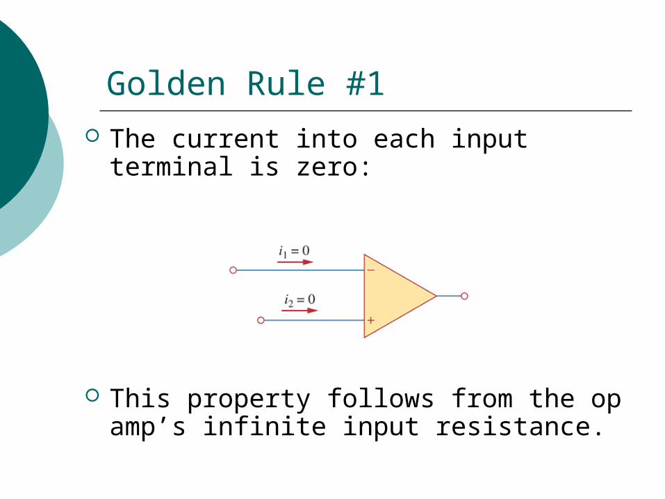
Golden Rule #1
The current into each input terminal is zero:
This property follows from the op amp’s infinite input resistance.
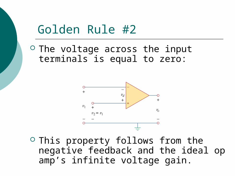
Golden Rule #2
The voltage across the input terminals is equal to zero:
This property follows from the negative feedback and the ideal op amp’s infinite voltage gain.
Five Standard Op-Amp Configurations Op amps are often combined with other
elements to form one of the following five standard configurations:1. Inverting Amplifier2. Non-inverting Amplifier3. Voltage Follower4. Summing Amplifier5. Difference Amplifier
You can use the two golden rules to analyze any of these circuits. But you’ll save time if you learn to recognize these standard configurations and remember their equations.
Standard Op-Amp Configuration #1
Op amps are very often combined with other elements to form one of the following five standard configurations:1. Inverting Amplifier2. Non-inverting Amplifier3. Voltage Follower4. Summing Amplifier5. Difference Amplifier
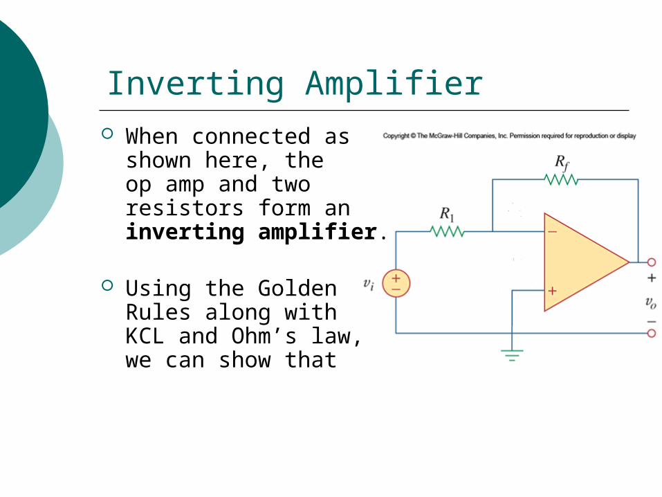
Inverting Amplifier When connected as
shown here, the op amp and two resistors form an inverting amplifier.
Using the Golden Rules along with KCL and Ohm’s law, we can show that
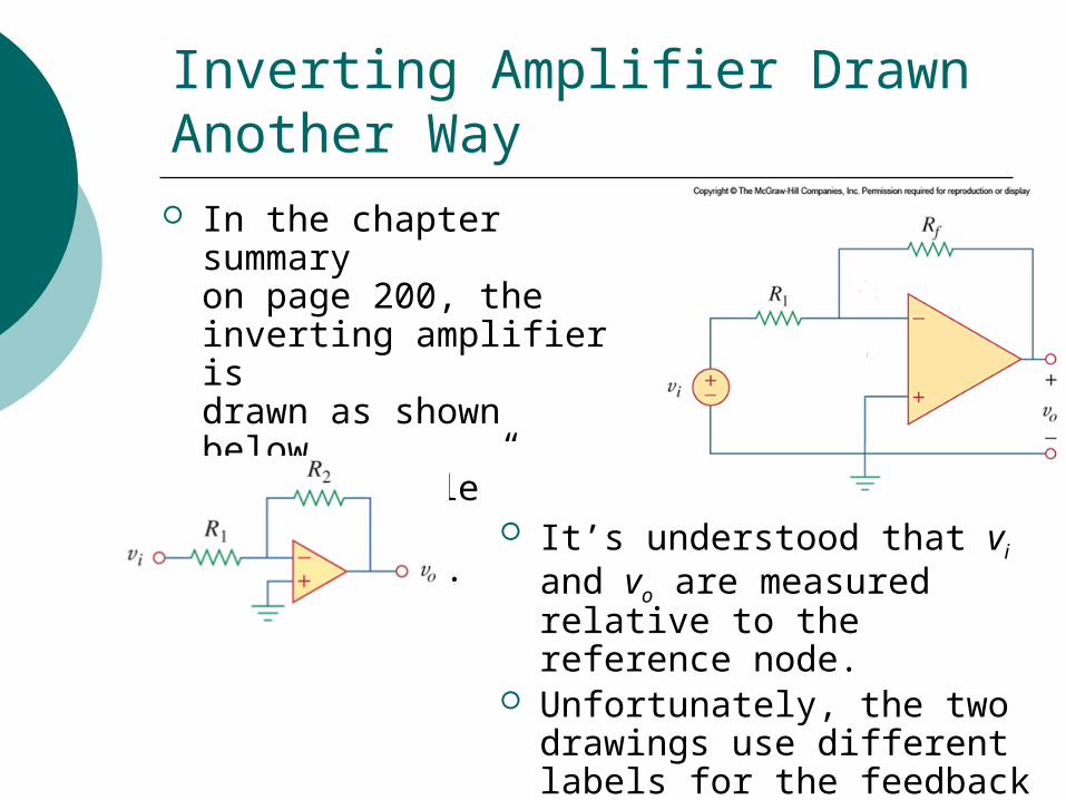
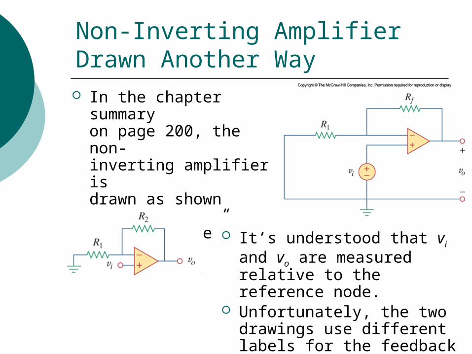
Inverting Amplifier Drawn Another Way In the chapter summary
on page 200, theinverting amplifier is drawn as shown below,using “bubble” symbolsfor vi and vo.
It’s understood that vi and vo are measured relative to the reference node.
Unfortunately, the two drawings use different labels for the feedback resistor. (Rf versus R2)
Standard Op-Amp Configuration #2
Op amps are very often combined with other elements to form one of the following five standard configurations:1. Inverting Amplifier
2. Non-inverting Amplifier3. Voltage Follower4. Summing Amplifier5. Difference Amplifier
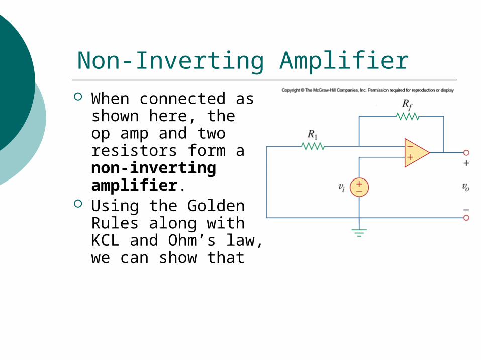
Non-Inverting Amplifier When connected as
shown here, the op amp and two resistors form a non-inverting amplifier.
Using the Golden Rules along with KCL and Ohm’s law, we can show that
Non-Inverting Amplifier Drawn Another Way In the chapter summary
on page 200, the non-inverting amplifier is drawn as shown below,using “bubble” symbolsfor vi and vo.
It’s understood that vi and vo are measured relative to the reference node.
Unfortunately, the two drawings use different labels for the feedback resistor. (Rf versus R2)
A Special Case of a Non-Inverting Amplifier
Suppose that in a non-inverting amplifier we let Rf = 0 and R1 = ∞.
Since for a non-inverting amplifier, we can easily see that this will give us
This special case is quite common and has its own name….
Standard Op-Amp Configuration #3
Op amps are very often combined with other elements to form one of the following five standard configurations:1. Inverting Amplifier2. Non-inverting Amplifier
3. Voltage Follower4. Summing Amplifier5. Difference Amplifier
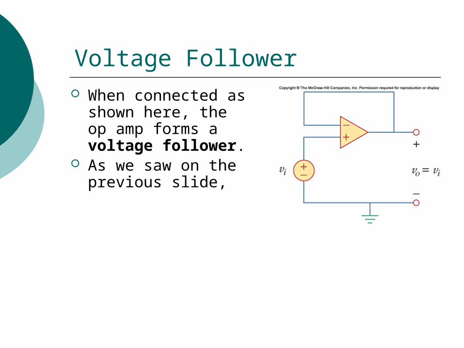
Voltage Follower When connected as
shown here, the op amp forms a voltage follower.
As we saw on the previous slide,
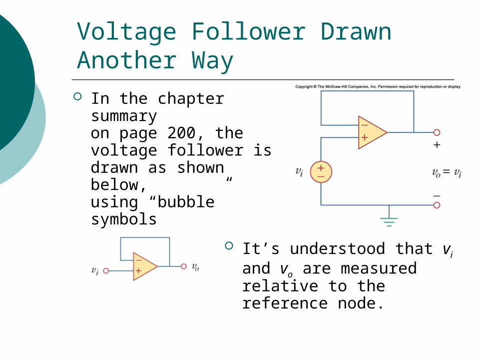
Voltage Follower Drawn Another Way In the chapter summary
on page 200, thevoltage follower is drawn as shown below,using “bubble” symbolsfor vi and vo.
It’s understood that vi and vo are measured relative to the reference node.
Standard Op-Amp Configuration #4
Op amps are very often combined with other elements to form one of the following five standard configurations:1. Inverting Amplifier2. Non-inverting Amplifier3. Voltage Follower
4. Summing Amplifier5. Difference Amplifier
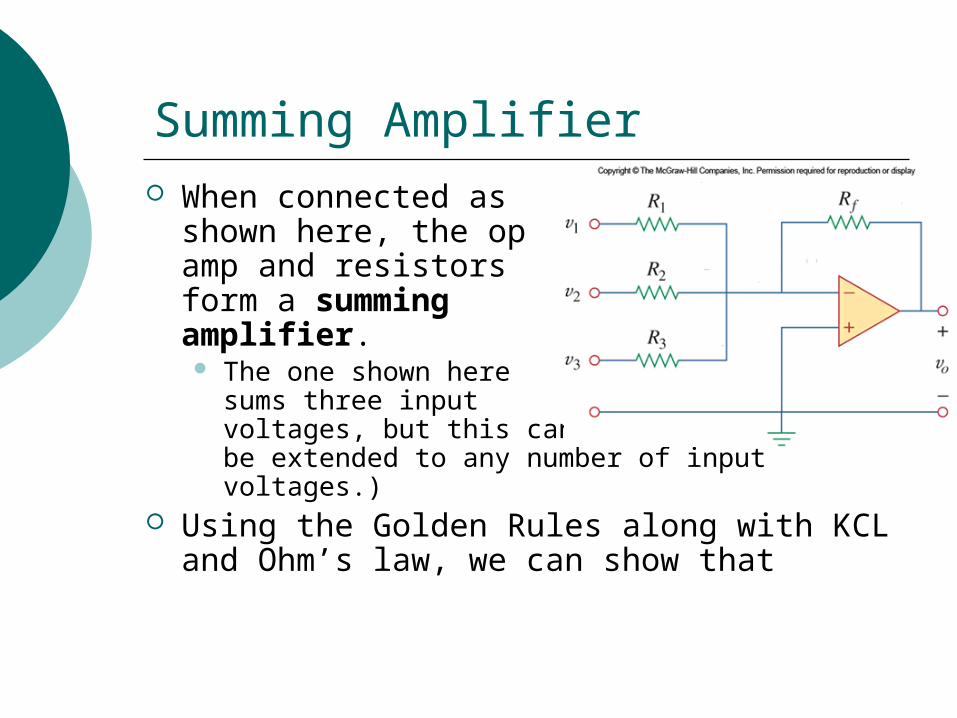
Summing Amplifier When connected as
shown here, the op amp and resistors form a summing amplifier. The one shown here
sums three input voltages, but this can be extended to any number of input voltages.)
Using the Golden Rules along with KCL and Ohm’s law, we can show that
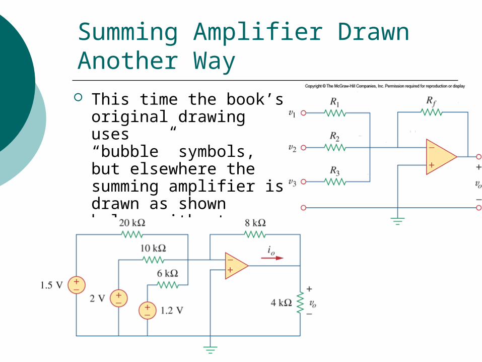
Summing Amplifier Drawn Another Way This time the book’s
original drawing uses“bubble” symbols, but elsewhere the summing amplifier is drawn as shown below, without bubbles.
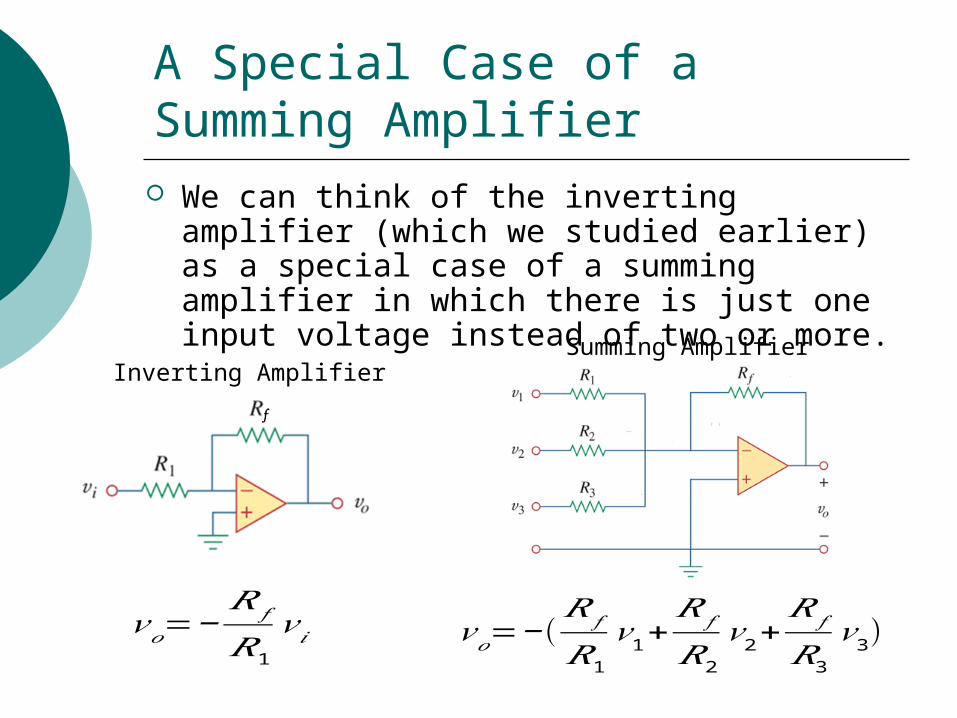
A Special Case of a Summing Amplifier We can think of the inverting amplifier (which
we studied earlier) as a special case of a summing amplifier in which there is just one input voltage instead of two or more.
Inverting AmplifierSumming Amplifier
𝑣𝑜=−(𝑅 𝑓
𝑅1
𝑣1+𝑅 𝑓
𝑅2
𝑣2+𝑅 𝑓
𝑅3
𝑣3)𝑣𝑜=−𝑅𝑓
𝑅1
𝑣 𝑖
Standard Op-Amp Configuration #5
Op amps are very often combined with other elements to form one of the following five standard configurations:1. Inverting Amplifier2. Non-inverting Amplifier3. Voltage Follower4. Summing Amplifier
5. Difference Amplifier
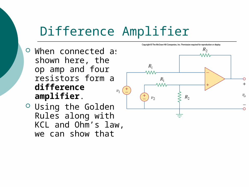
Difference Amplifier When connected as
shown here, the op amp and four resistors form a difference amplifier.
Using the Golden Rules along with KCL and Ohm’s law, we can show that
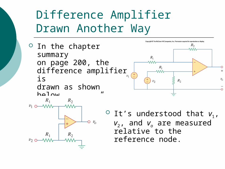
Difference Amplifier Drawn Another Way
In the chapter summaryon page 200, thedifference amplifier is drawn as shown below,using “bubble” symbolsfor vi and vo.
It’s understood that v1, v2, and vo are measured relative to the reference node.
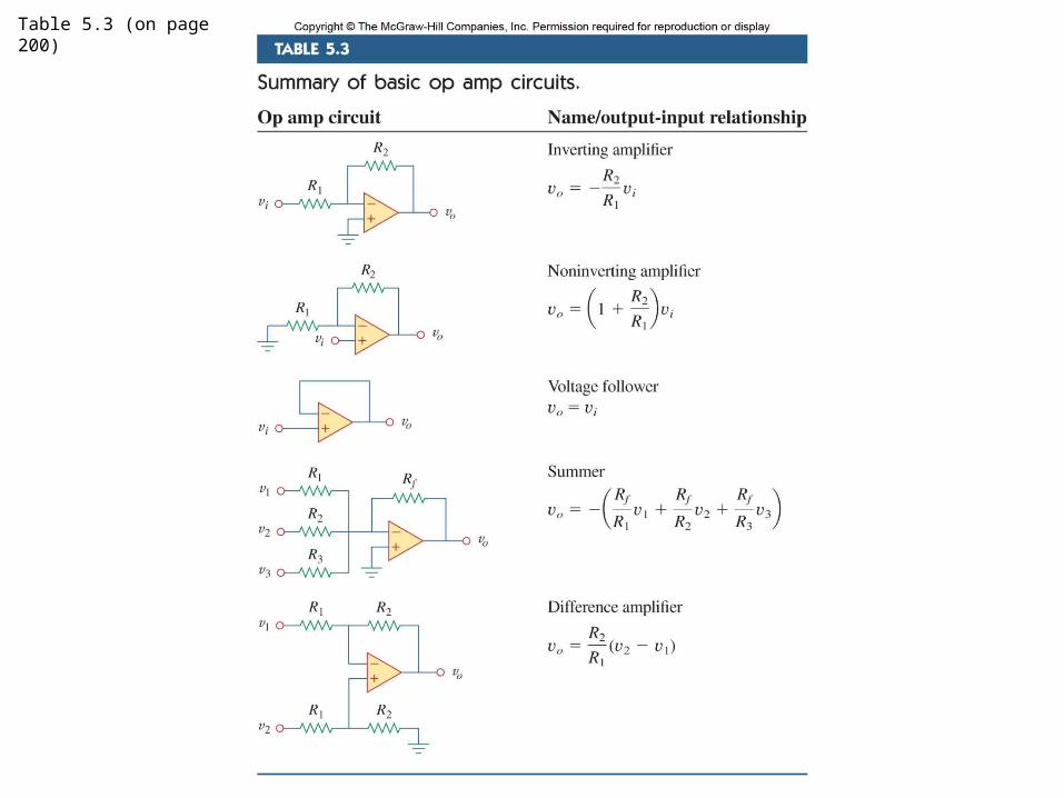
Table 5.3 (on page 200)
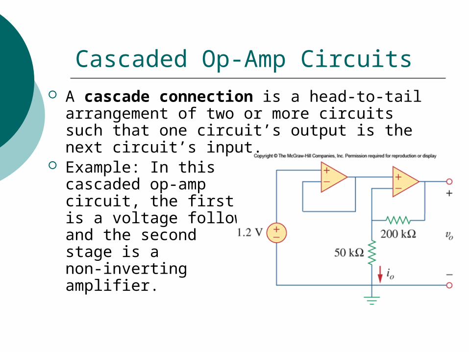
Cascaded Op-Amp Circuits A cascade connection is a head-to-tail
arrangement of two or more circuits such that one circuit’s output is the next circuit’s input.
Example: In this cascaded op-amp circuit, the first stage is a voltage follower, and the second stage is a non-inverting amplifier.


![[Solutions Manual] EMTL - Sadiku - 3rd](https://img.pdfslide.us/doc/110x75/5535ee574a79593c148b481d/solutions-manual-emtl-sadiku-3rd.jpg)