Embed Size (px)
Citation preview
EGR 2201 Unit 2Basic Laws
Read Alexander & Sadiku, Chapter 2. Homework #2 and Lab #2 due next
week. Quiz next week.
Ohm’s Law
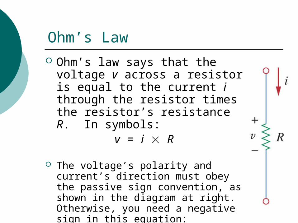
Ohm’s law says that the voltage v across a resistor is equal to the current i through the resistor times the resistor’s resistance R. In symbols:
v = i R
The voltage’s polarity and current’s direction must obey the passive sign convention, as shown in the diagram at right. Otherwise, you need a negative sign in this equation: v = i R.
Ohm’s Law Rearranged
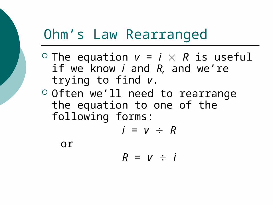
The equation v = i R is useful if we know i and R, and we’re trying to find v.
Often we’ll need to rearrange the equation to one of the following forms:
i = v R or
R = v i
Short Circuit
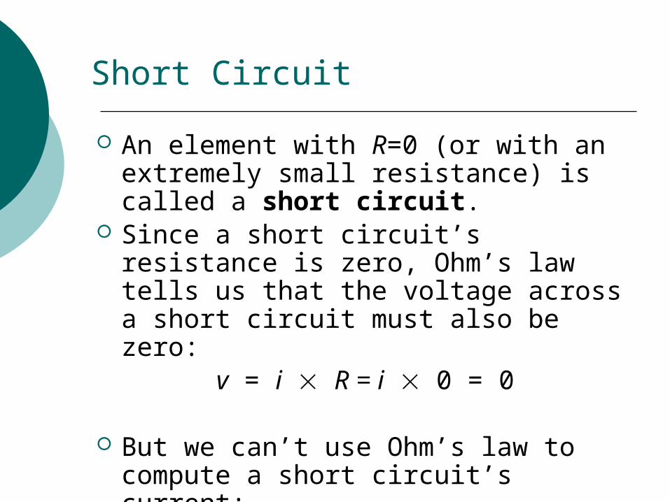
An element with R=0 (or with an extremely small resistance) is called a short circuit.
Since a short circuit’s resistance is zero, Ohm’s law tells us that the voltage across a short circuit must also be zero:
v = i R = i 0 = 0
But we can’t use Ohm’s law to compute a short circuit’s current:
i = v R = 0 0 = ???
Open Circuit
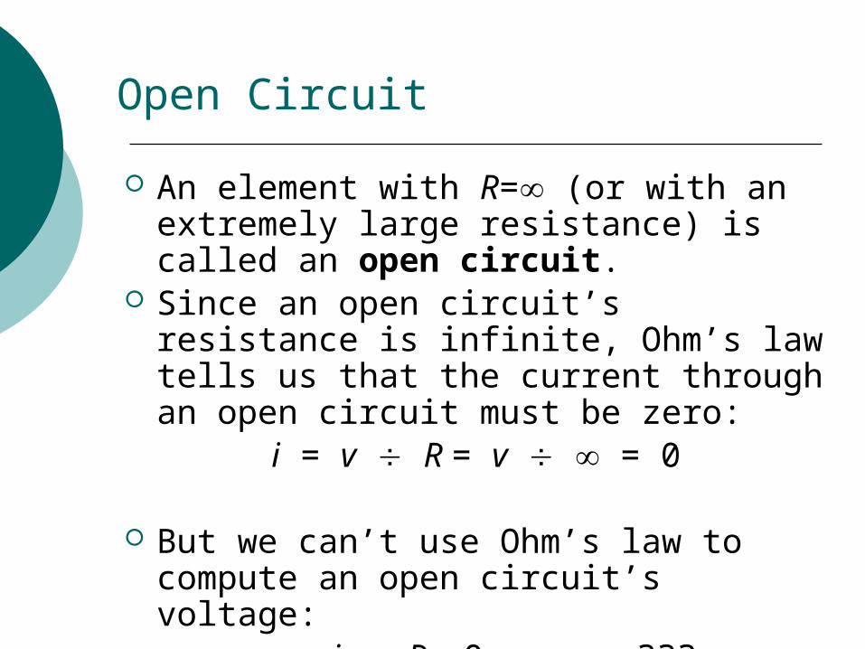
An element with R= (or with an extremely large resistance) is called an open circuit.
Since an open circuit’s resistance is infinite, Ohm’s law tells us that the current through an open circuit must be zero:
i = v R = v = 0
But we can’t use Ohm’s law to compute an open circuit’s voltage:
v = i R = 0 = ???
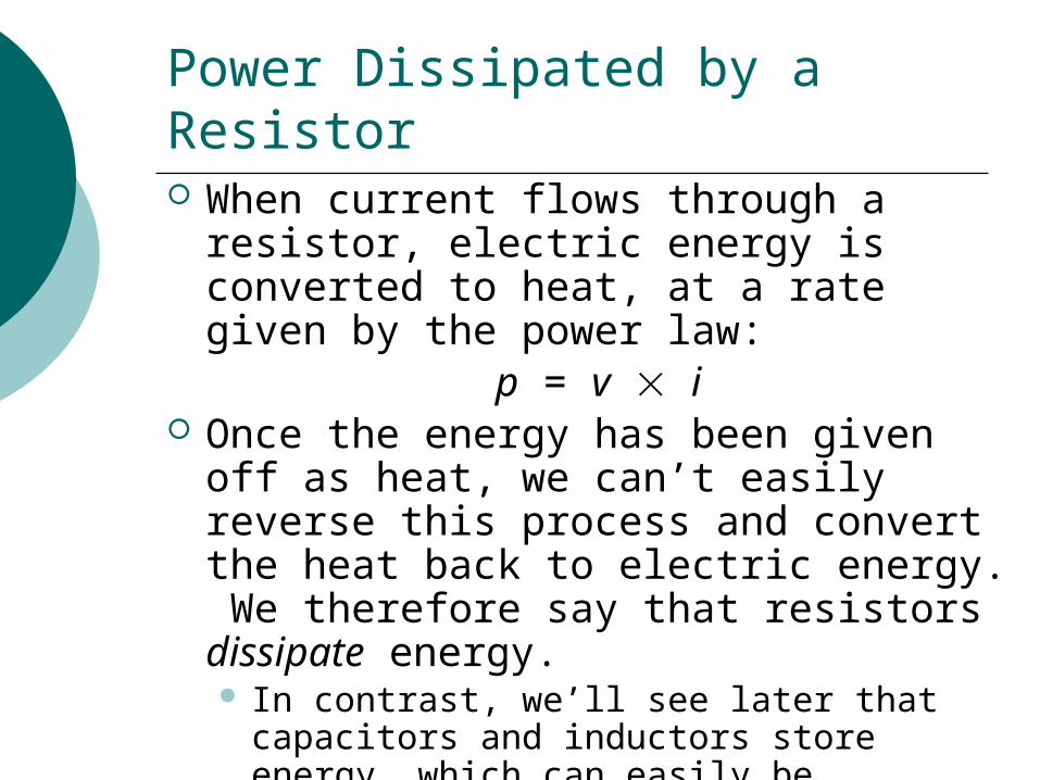
Power Dissipated by a Resistor When current flows through a resistor,
electric energy is converted to heat, at a rate given by the power law:
p = v i Once the energy has been given off as
heat, we can’t easily reverse this process and convert the heat back to electric energy. We therefore say that resistors dissipate energy. In contrast, we’ll see later that capacitors
and inductors store energy, which can easily be recovered.
Other Power Formulas for Resistors
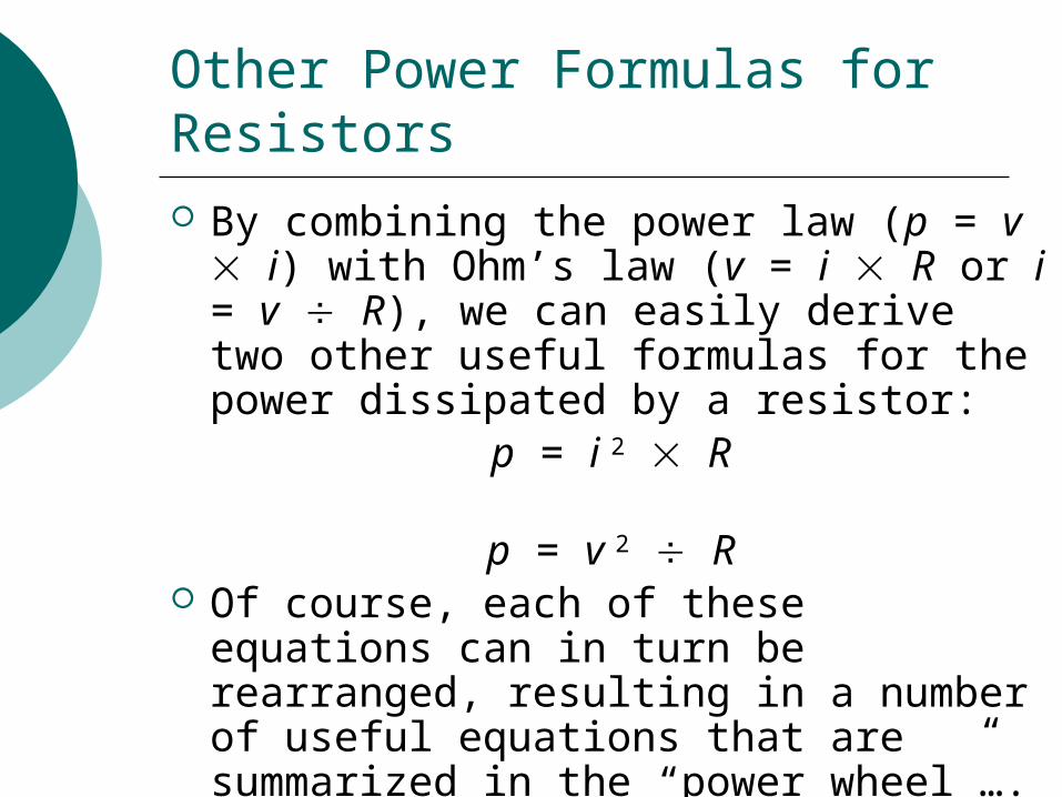
By combining the power law (p = v i) with Ohm’s law (v = i R or i = v R), we can easily derive two other useful formulas for the power dissipated by a resistor:
p = i 2 R
p = v 2 R Of course, each of these equations can
in turn be rearranged, resulting in a number of useful equations that are summarized in the “power wheel”….
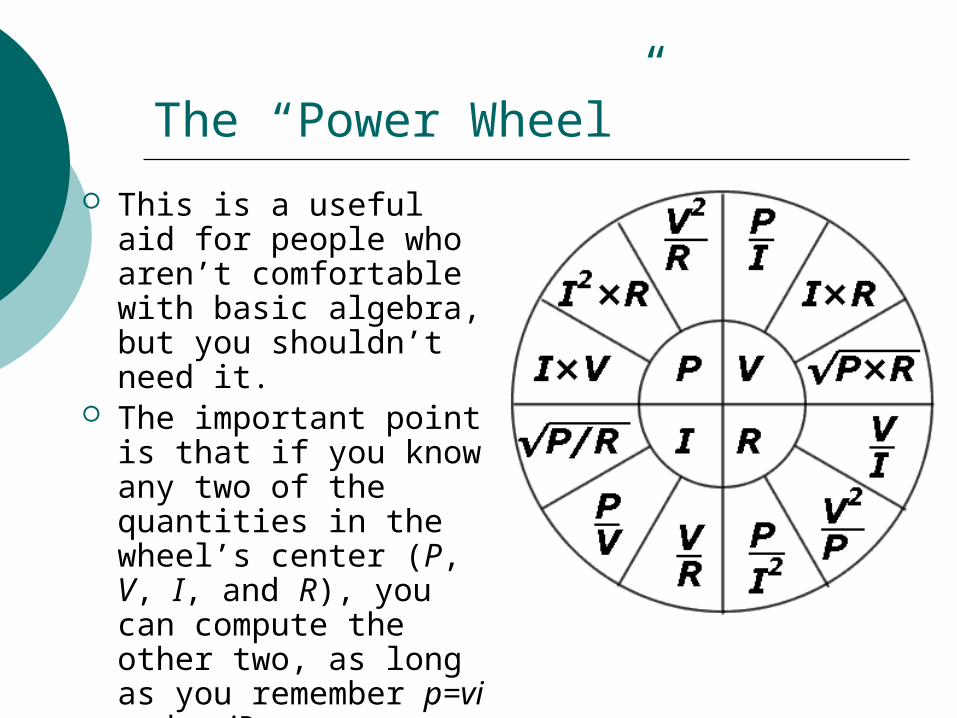
The “Power Wheel”
This is a useful aid for people who aren’t comfortable with basic algebra, but you shouldn’t need it.
The important point is that if you know any two of the quantities in the wheel’s center (P, V, I, and R), you can compute the other two, as long as you remember p=vi and v=iR.
Conductance
It’s sometimes useful to work with the reciprocal of resistance, which we call conductance.
The symbol for conductance is G:G = 1 R
Its unit of measure is the siemens (S).
Example: If a resistor’s resistance is 20 , its conductance is 50 mS.
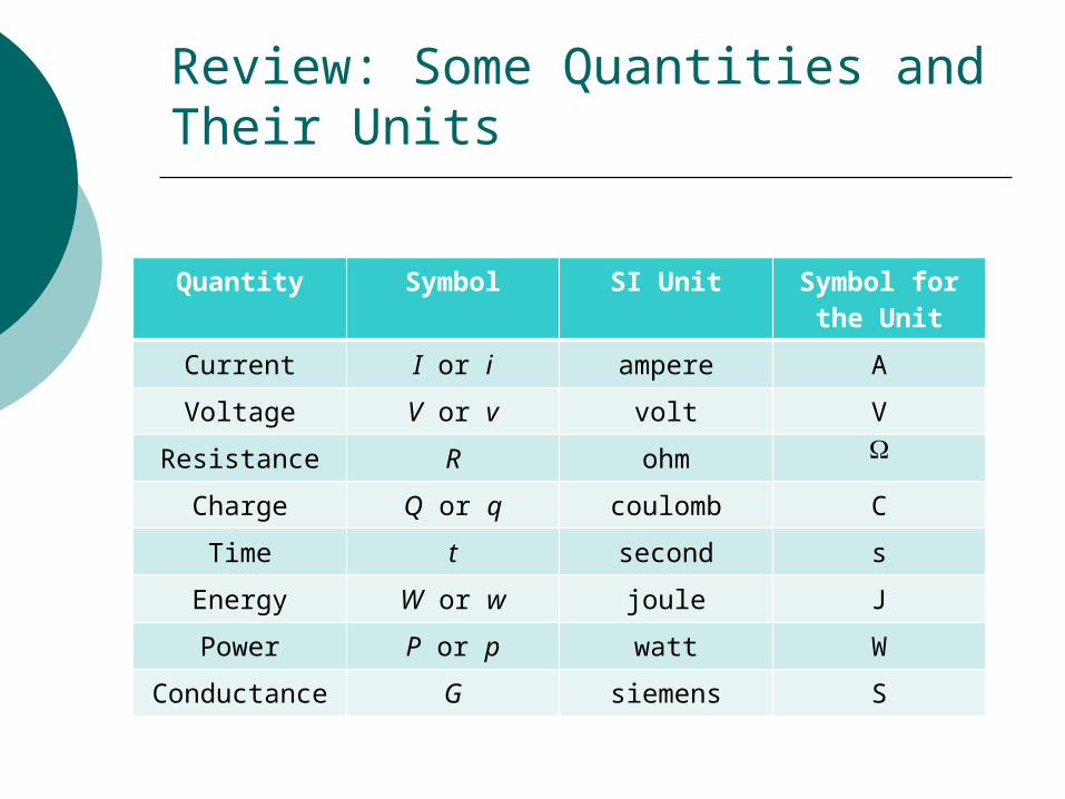
Review: Some Quantities and Their Units
Quantity Symbol SI Unit Symbol for the Unit
Current I or i ampere A
Voltage V or v volt V
Resistance R ohm
Charge Q or q coulomb C
Time t second s
Energy W or w joule J
Power P or p watt W
Conductance G siemens S
Ohm’s Law and the Power Formulas Using Conductance
As the book discusses, Ohm’s law and our power formulas can be rewritten using conductance G instead of resistance R.
Example: Instead of writing
v = i R we can write
v = i G But I advise you to ignore this, and
always use R instead of G.
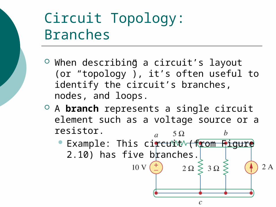
Circuit Topology: Branches
When describing a circuit’s layout (or “topology”), it’s often useful to identify the circuit’s branches, nodes, and loops.
A branch represents a single circuit element such as a voltage source or a resistor. Example: This circuit (from Figure 2.10)
has five branches.
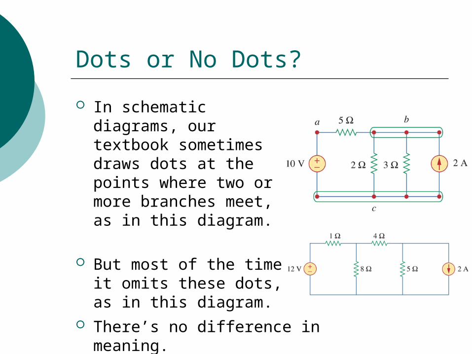
Dots or No Dots?
In schematic diagrams, our textbook sometimes draws dots at the points where two or more branches meet, as in this diagram.
But most of the time it omits these dots, as in this diagram.
There’s no difference in meaning.
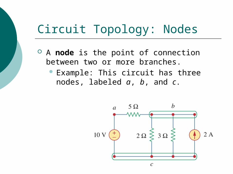
Circuit Topology: Nodes
A node is the point of connection between two or more branches. Example: This circuit has three nodes,
labeled a, b, and c.
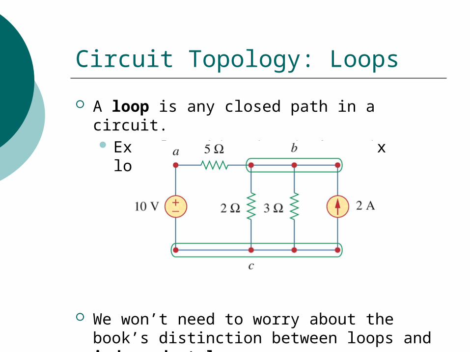
Circuit Topology: Loops
A loop is any closed path in a circuit. Example: This circuit has six loops.
We won’t need to worry about the book’s distinction between loops and independent loops.
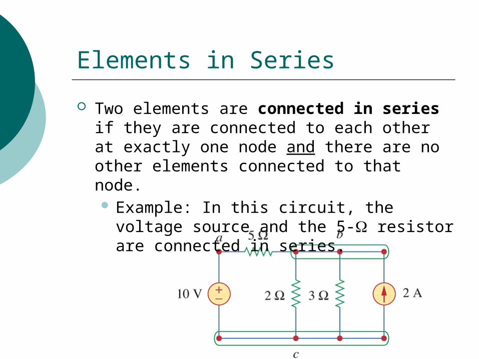
Elements in Series
Two elements are connected in series if they are connected to each other at exactly one node and there are no other elements connected to that node. Example: In this circuit, the voltage source
and the 5- resistor are connected in series.
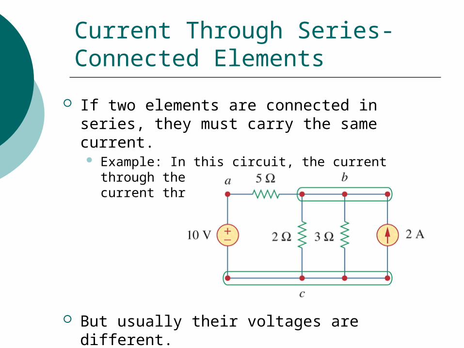
If two elements are connected in series, they must carry the same current. Example: In this circuit, the current through the
voltage source must equal the current through the 5- resistor.
But usually their voltages are different. Example: In the circuit above, we wouldn’t expect
the voltage across the 5- resistor to be 10 V.
Current Through Series-Connected Elements
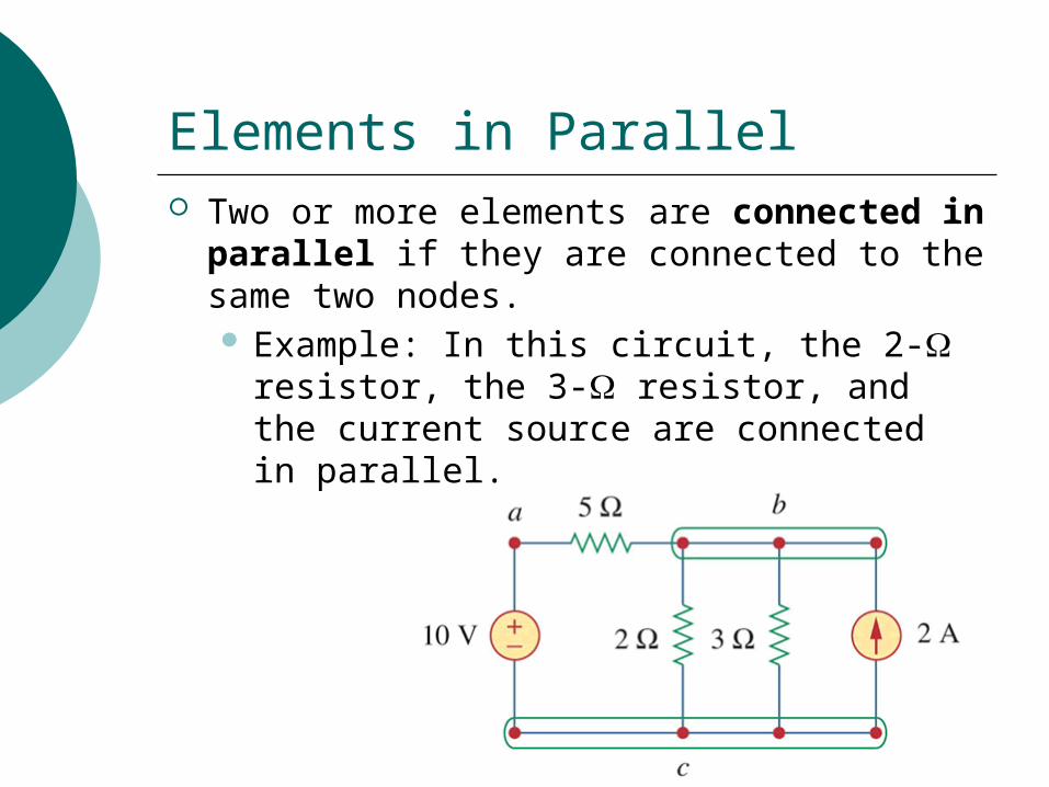
Elements in Parallel Two or more elements are connected in
parallel if they are connected to the same two nodes. Example: In this circuit, the 2- resistor,
the 3- resistor, and the current source are connected in parallel.
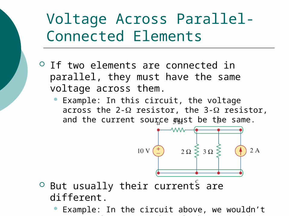
If two elements are connected in parallel, they must have the same voltage across them. Example: In this circuit, the voltage across the 2-
resistor, the 3- resistor, and the current source must be the same.
But usually their currents are different. Example: In the circuit above, we wouldn’t expect
the current through the 3- resistor to be 2 A.
Voltage Across Parallel-Connected Elements
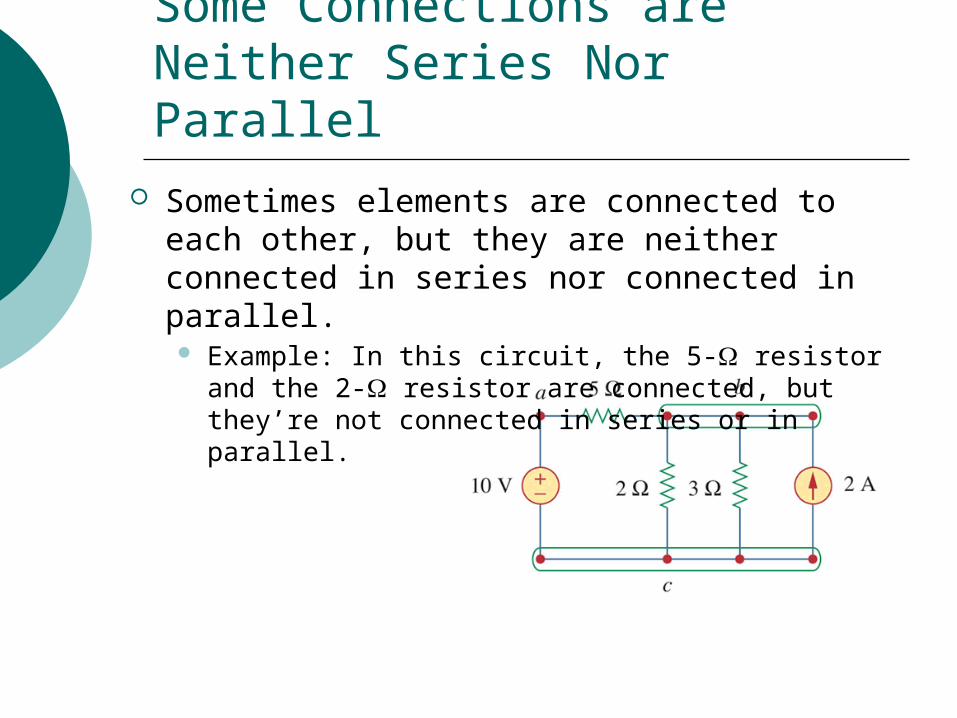
Sometimes elements are connected to each other, but they are neither connected in series nor connected in parallel. Example: In this circuit, the 5- resistor and the 2-
resistor are connected, but they’re not connected in series or in parallel.
In such a case, we wouldn’t expect the two elements to have the same current or the same voltage.
This type of connection doesn’t have a special name.
Some Connections are Neither Series Nor Parallel
Series Circuits
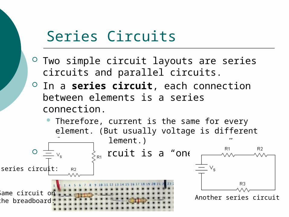
Two simple circuit layouts are series circuits and parallel circuits.
In a series circuit, each connection between elements is a series connection. Therefore, current is the same for every element.
(But usually voltage is different for every element.) A series circuit is a “one-loop” circuit.
Another series circuit
A series circuit:
Same circuit on the breadboard:
Analyzing a Series Circuit
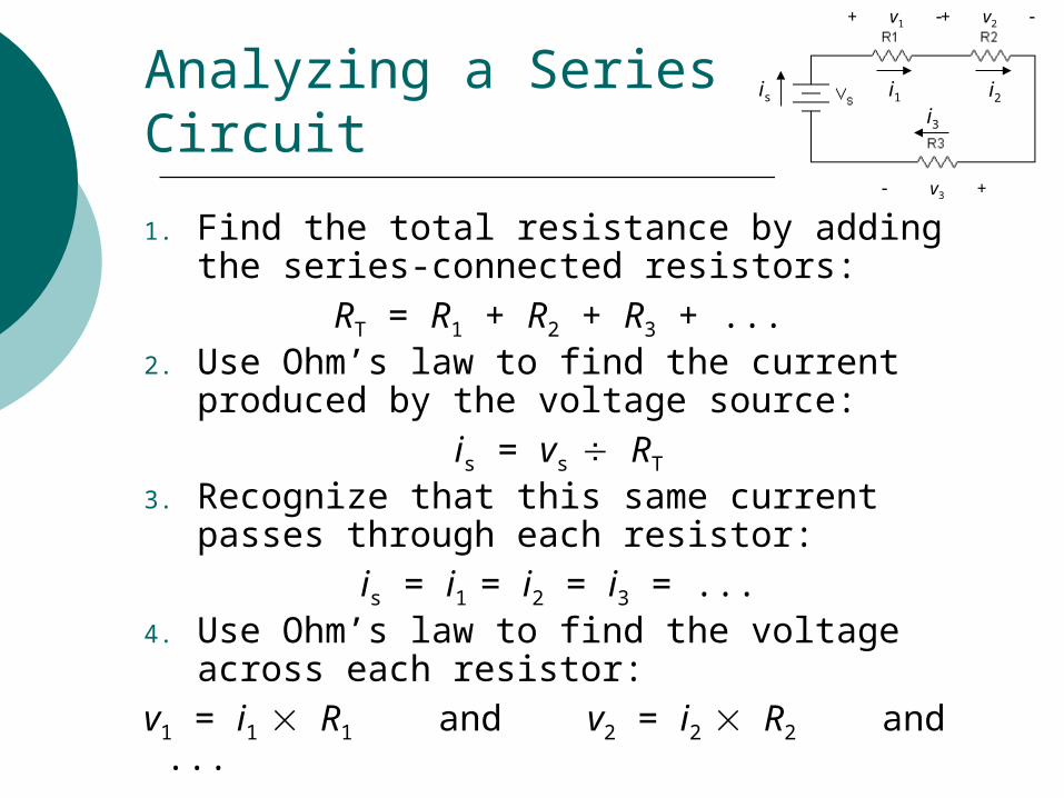
1. Find the total resistance by adding the series-connected resistors:
RT = R1 + R2 + R3 + ...2. Use Ohm’s law to find the current
produced by the voltage source:is = vs RT
3. Recognize that this same current passes through each resistor:
is = i1 = i2 = i3 = ...4. Use Ohm’s law to find the voltage across
each resistor:v1 = i1 R1 and v2 = i2 R2 and ...
+ v1 + v2
v3 +
is i1 i2i3
Parallel Circuits
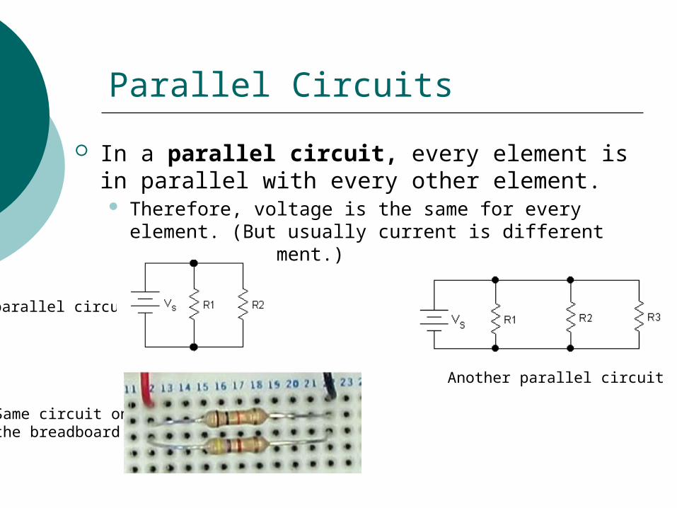
In a parallel circuit, every element is in parallel with every other element. Therefore, voltage is the same for every element.
(But usually current is different for every element.)
Another parallel circuit
A parallel circuit:
Same circuit on the breadboard:
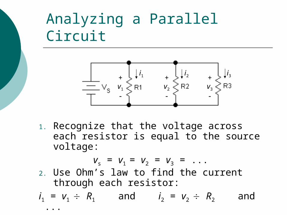
Analyzing a Parallel Circuit
1. Recognize that the voltage across each resistor is equal to the source voltage:
vs = v1 = v2 = v3 = ...2. Use Ohm’s law to find the current through
each resistor:i1 = v1 R1 and i2 = v2 R2 and ...
+v1
+v2
+v3
i1 i2 i3
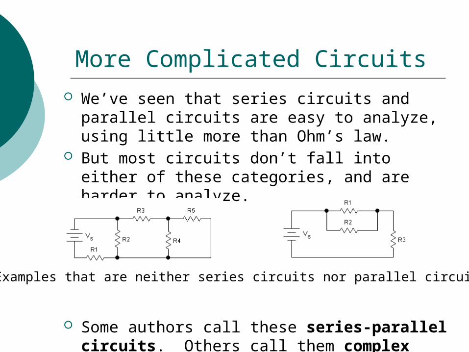
We’ve seen that series circuits and parallel circuits are easy to analyze, using little more than Ohm’s law.
But most circuits don’t fall into either of these categories, and are harder to analyze.
Some authors call these series-parallel circuits. Others call them complex circuits.
More Complicated Circuits
Examples that are neither series circuits nor parallel circuits
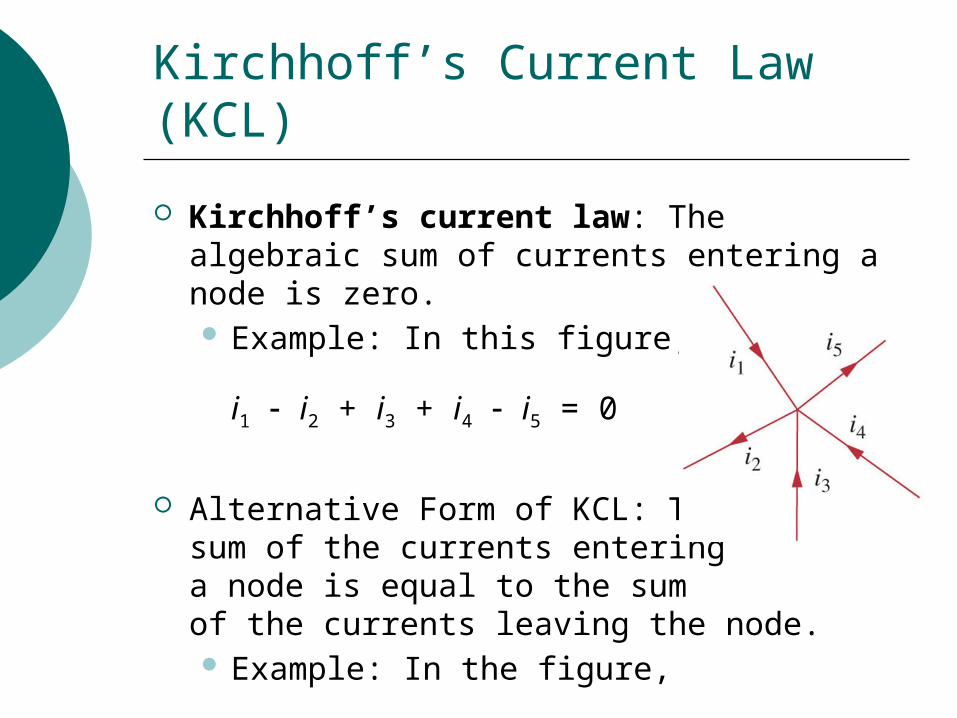
Kirchhoff’s Current Law (KCL)
Kirchhoff’s current law: The algebraic sum of currents entering a node is zero. Example: In this figure,
i1 i2 + i3 + i4 i5 = 0
Alternative Form of KCL: The sum of the currents entering a node is equal to the sum of the currents leaving the node. Example: In the figure,
i1 + i3 + i4 = i2 + i5
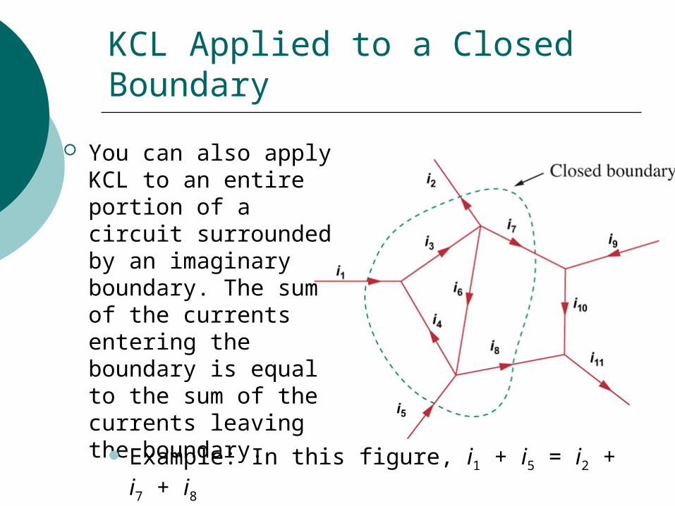
KCL Applied to a Closed Boundary
You can also apply KCL to an entire portion of a circuit surrounded by an imaginary boundary. The sum of the currents entering the boundary is equal to the sum of the currents leaving the boundary.
Example: In this figure, i1 + i5 = i2 + i7 + i8
Kirchhoff’s Voltage Law (KVL)
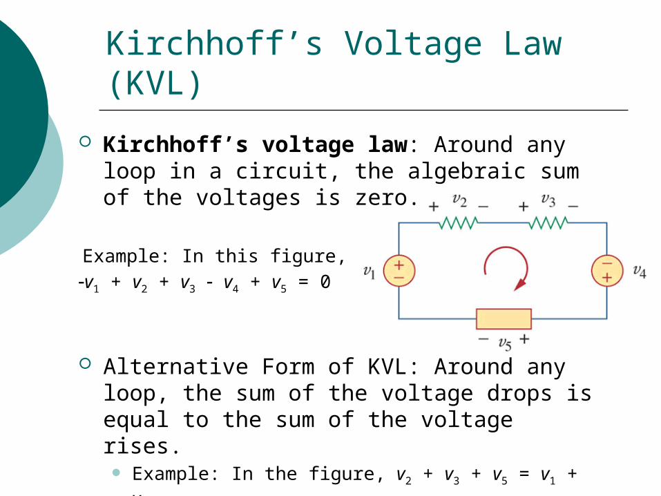
Kirchhoff’s voltage law: Around any loop in a circuit, the algebraic sum of the voltages is zero.
Example: In this figure,v1 + v2 + v3 v4 + v5 = 0
Alternative Form of KVL: Around any loop, the sum of the voltage drops is equal to the sum of the voltage rises. Example: In the figure, v2 + v3 + v5 = v1 + v4
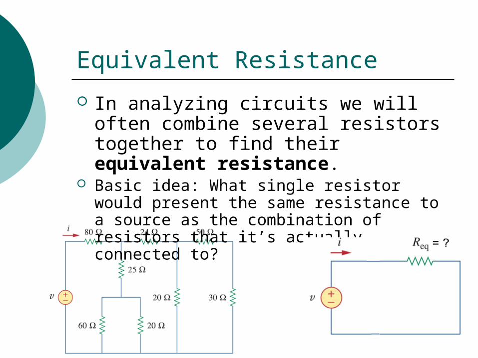
Equivalent Resistance
In analyzing circuits we will often combine several resistors together to find their equivalent resistance.
Basic idea: What single resistor would present the same resistance to a source as the combination of resistors that it’s actually connected to?
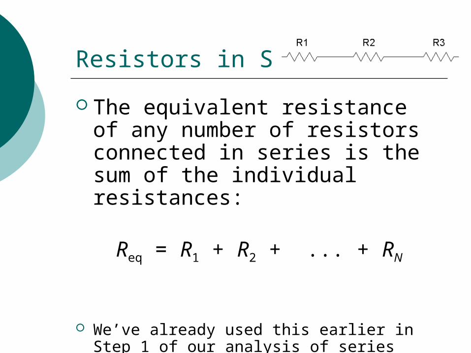
Resistors in Series
The equivalent resistance of any number of resistors connected in series is the sum of the individual resistances:
Req = R1 + R2 + ... + RN
We’ve already used this earlier in Step 1 of our analysis of series circuits.
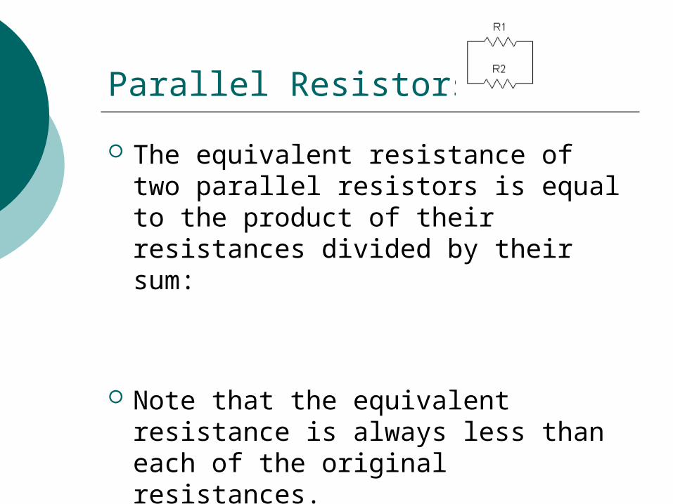
Parallel Resistors
The equivalent resistance of two parallel resistors is equal to the product of their resistances divided by their sum:
Note that the equivalent resistance is always less than each of the original resistances.
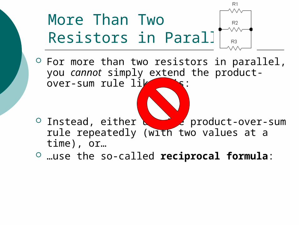
More Than Two Resistors in Parallel
For more than two resistors in parallel, you cannot simply extend the product-over-sum rule like this:
Instead, either use the product-over-sum rule repeatedly (with two values at a time), or…
…use the so-called reciprocal formula:
Parallel Resistors: Two Shortcut Rules for Special Cases
Special Case #1: For N parallel resistors, each having resistance R,
Special Case #2: When one resistance is much less than another one connected in parallel with it, the equivalent resistance is very nearly equal to the smaller one:
If R1 << R2, then Req R1
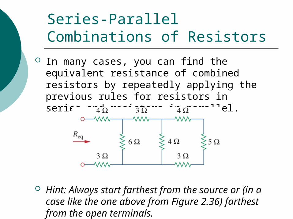
Series-Parallel Combinations of Resistors
In many cases, you can find the equivalent resistance of combined resistors by repeatedly applying the previous rules for resistors in series and resistors in parallel.
Hint: Always start farthest from the source or (in a case like the one above from Figure 2.36) farthest from the open terminals.
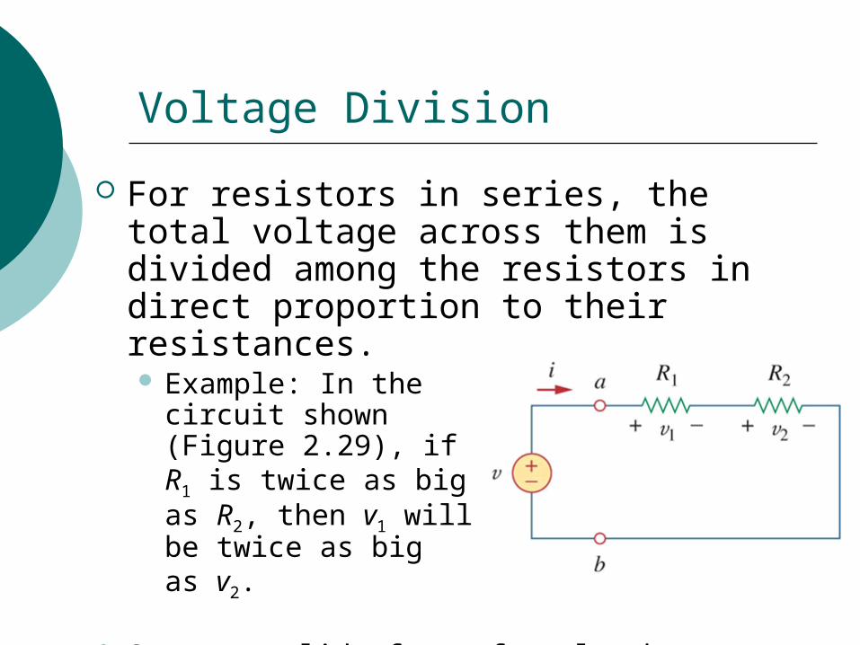
Voltage Division
For resistors in series, the total voltage across them is divided among the resistors in direct proportion to their resistances. Example: In the
circuit shown(Figure 2.29), if R1 is twice as big as R2, then v1 will be twice as big as v2.
See next slide for a formula that captures this…
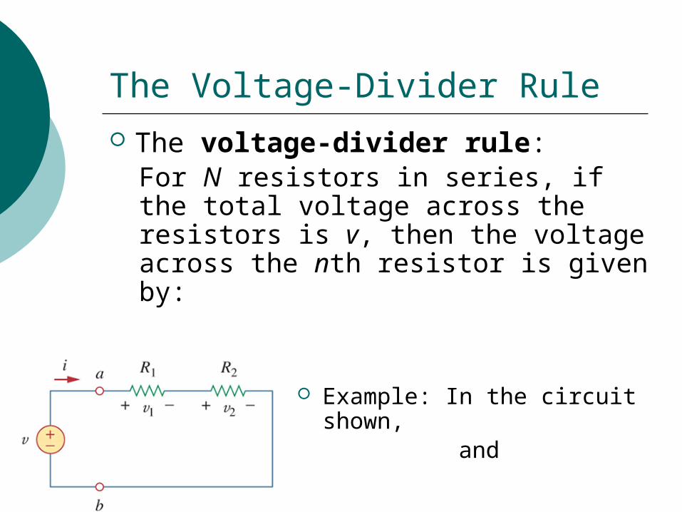
The Voltage-Divider Rule
The voltage-divider rule:For N resistors in series, if the total voltage across the resistors is v, then the voltage across the nth resistor is given by:
Example: In the circuit shown, and
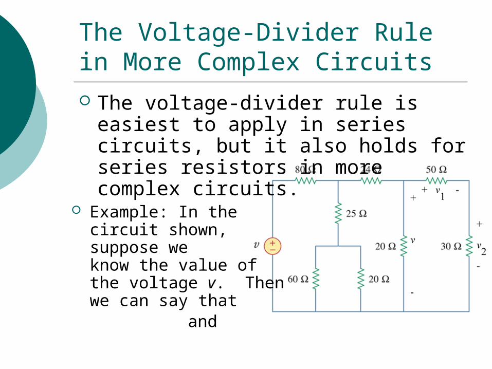
The Voltage-Divider Rule in More Complex Circuits
The voltage-divider rule is easiest to apply in series circuits, but it also holds for series resistors in more complex circuits.
Example: In the circuit shown, suppose we know the value of the voltage v. Then we can say that
and
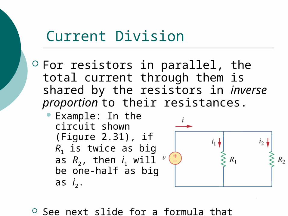
Current Division
For resistors in parallel, the total current through them is shared by the resistors in inverse proportion to their resistances. Example: In the
circuit shown(Figure 2.31), if R1 is twice as big as R2, then i1 will be one-half as big as i2.
See next slide for a formula that captures this…
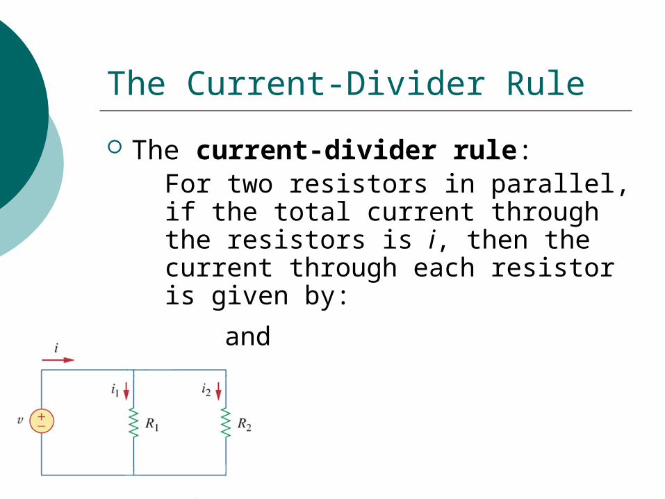
The Current-Divider Rule
The current-divider rule:For two resistors in parallel, if the total current through the resistors is i, then the current through each resistor is given by:
and
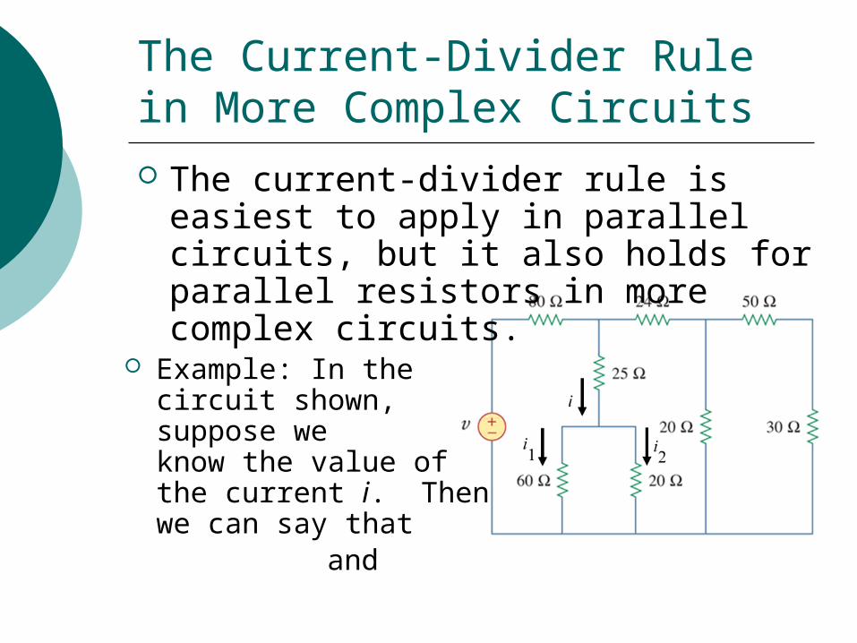
The Current-Divider Rule in More Complex Circuits
The current-divider rule is easiest to apply in parallel circuits, but it also holds for parallel resistors in more complex circuits.
Example: In the circuit shown, suppose we know the value of the current i. Then we can say that
and
Review of Short Circuits
Recall that an element with R=0 (or with an extremely small resistance) is called a short circuit.
Recall also that, since the resistance of a short circuit is zero, the voltage across it must always be zero.
Sometimes short circuits are introduced intentionally into a circuit, but often they result from a circuit failure.
New Observations about Short Circuits
The equivalent resistance of a short circuit in parallel with anything else is zero.
An element or portion of a circuit is short-circuited, or “shorted out,” when there is a short circuit in parallel with it.
No current flows in a short-circuited element; instead all current is diverted through the short circuit itself.
Series-Aiding Voltage Sources
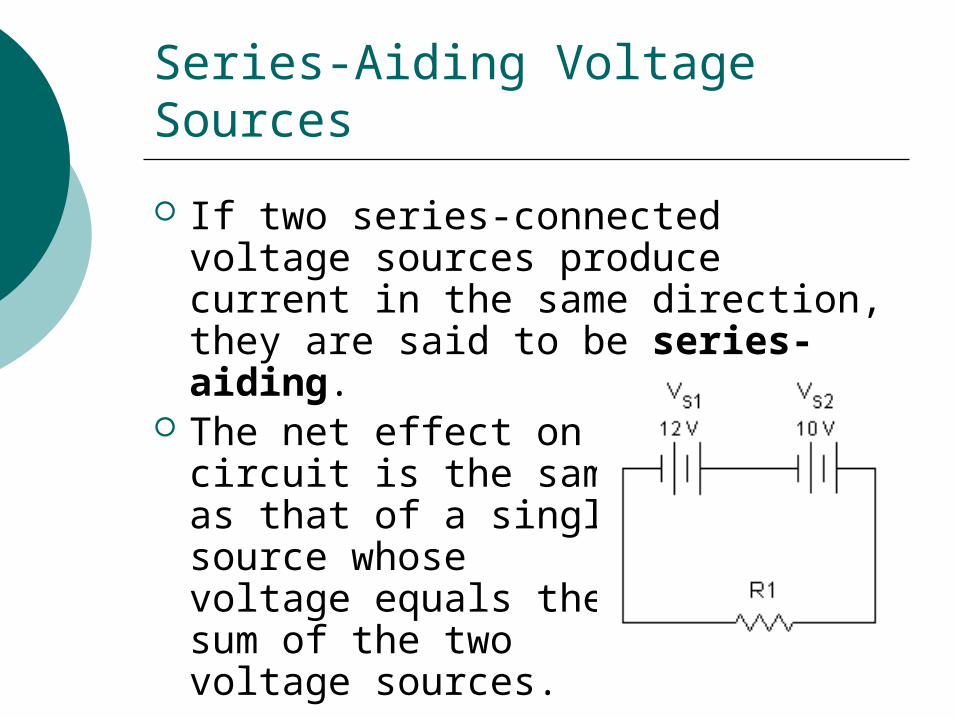
If two series-connected voltage sources produce current in the same direction, they are said to be series-aiding.
The net effect on thecircuit is the sameas that of a singlesource whose voltage equals the sum of the two voltage sources.
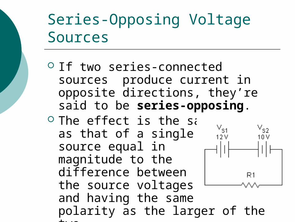
Series-Opposing Voltage Sources
If two series-connected sources produce current in opposite directions, they’re said to be series-opposing.
The effect is the sameas that of a single source equal in magnitude to the difference between the source voltages and having the same polarity as the larger of the two.
Series-Connected Current Sources?
Current sources are not connected in series.
Potentiometers & Rheostats
A potentiometer is an adjustable voltage divider that is widely used in a variety of electronic circuit applications. It is a three-terminal device.
A rheostat is an adjustable resistance. It has only two terminals.
Parallel Voltage Sources
Different-valued voltage sources are not connected in parallel. Exception: rechargeable batteries.
Two identical voltage sources, having the same voltage and the same internal resistance, can be connected in parallel.
Parallel Current Sources
Equal- or different-valued current sources can be connected in parallel. The parallel-connected sources can be replaced by a single equivalent current source that produces a current equal to the algebraic sum (resultant) of the several sources.


![[Solutions Manual] EMTL - Sadiku - 3rd](https://img.pdfslide.us/doc/110x75/5535ee574a79593c148b481d/solutions-manual-emtl-sadiku-3rd.jpg)