Embed Size (px)
Citation preview
Proceedings 8th International Mine Ventilation Congress, Brisbane, Australia, 6-8 July 2005.
1
EFFECTS OF VENTILATION LEAKAGE IN DEEP, HOT ROOM + PILLAR
OPERATIONS
N Schophaus[1]
, S Bluhm[2]
and R Funnell[2]
1. Ventilation Manager New Mining Projects, Impala Platinum Ltd, Rustenburg, South Africa
2. Director, Bluhm Burton Engineering Pty Ltd. Sandton, South Africa
ABSTRACT
Creative mine-designs are constantly being applied in the deep platinum mining industry in South Africa. Recently, this has resulted in deep hot mine-designs including room+pillar, bord+pillar or stall+pillar layouts and the use of some degree of in-stope trackless mechanization. In these mines, the ventilation systems use refrigerated air and high fan pressures and ventilation leakage can have a huge impact. Leakage is a serious impediment to cost-effective operation and potential leakage in future projects is a major factor in judging project viability. This paper describes certain mine layouts and quantifies the extent of the leakage. Based on typical field data, a range of seals from ‘Very Poor’ to ‘Very Good’ was defined and used to estimate overall leakage. Within these mine networks, the ventilation pressure, temperature and density all vary significantly and, with the multiplicity of leakage paths, it was necessary to make use of the VUMA-network simulation package. For the examples examined, the leakage was found to be up to 85% for ‘Poor’ category seals and up to 50% for ‘Good’ category seals. The total air flow [and refrigeration] requirements grow exponentially with strike distance due to the compounding effects of higher pressure and more leakage paths. It is shown that, beyond certain depths and strike distances, the leakage will become so great that it will be impossible to operate cost-effectively - even with ‘Good’ seals. Indeed, in these examples, the projects were not considered viable in their original format because of the high ventilation-cooling costs and the mine-designs were modified to include footwall drive systems - the cost of which was justified by the reduced strategic risk to operating ineffectiveness due to leakage.
INTRODUCTION The platinum mining industry in South Africa has, in recent times, attracted numerous creative mine-design initiatives and, as a result, has experienced some variation in mining methodology. Traditionally the deeper operations use breast [or updip] stoping with scraper winches served by raise-lines with back lengths up to 350 m and footwall drives for tracked ore transport. However in some cases, the need to contain operating costs, minimize waste tonnages and improve productivity has led to alternative approaches. The relatively low-dip ore-body gives potential opportunity for layout variations and this has led to a renaissance in mine design which has included use of: strike drives with roadways or belt-conveyors on-reef dip conveyors [and roadways] on-reef main intake systems low profile loaders, drill-rigs and trucks various combinations/permutations/hybrids of the above The common theme in these designs is some form of room+pillar, bord+pillar or stall+pillar layout and, geology and narrow reef permitting, the use of some degree of in-stope trackless mechanization.
Proceedings 8th International Mine Ventilation Congress, Brisbane, Australia, 6-8 July 2005.
2
Initially, the design of the new ventilation systems drew heavily on traditional coal mining room+pillar practices* and those of the shallow narrow reef base metal operations mining from outcrops. These approaches soon proved to be inappropriate with primary ventilation leakage situations of 60% and greater being experienced. Many of these mines are [or will be] at depths exceeding 1 500 m in virgin rock temperatures up to 60
0C and the main ventilation
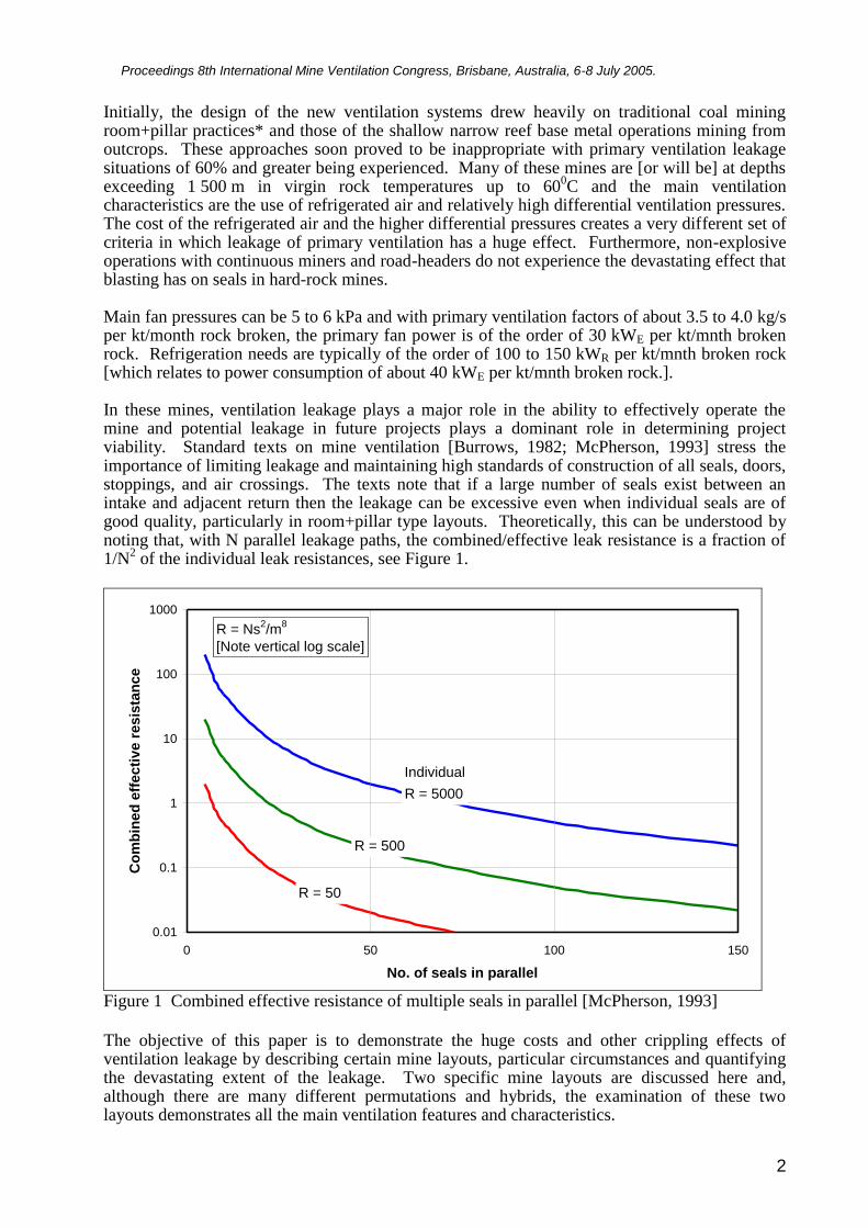
characteristics are the use of refrigerated air and relatively high differential ventilation pressures. The cost of the refrigerated air and the higher differential pressures creates a very different set of criteria in which leakage of primary ventilation has a huge effect. Furthermore, non-explosive operations with continuous miners and road-headers do not experience the devastating effect that blasting has on seals in hard-rock mines. Main fan pressures can be 5 to 6 kPa and with primary ventilation factors of about 3.5 to 4.0 kg/s per kt/month rock broken, the primary fan power is of the order of 30 kWE per kt/mnth broken rock. Refrigeration needs are typically of the order of 100 to 150 kWR per kt/mnth broken rock [which relates to power consumption of about 40 kWE per kt/mnth broken rock.]. In these mines, ventilation leakage plays a major role in the ability to effectively operate the mine and potential leakage in future projects plays a dominant role in determining project viability. Standard texts on mine ventilation [Burrows, 1982; McPherson, 1993] stress the importance of limiting leakage and maintaining high standards of construction of all seals, doors, stoppings, and air crossings. The texts note that if a large number of seals exist between an intake and adjacent return then the leakage can be excessive even when individual seals are of good quality, particularly in room+pillar type layouts. Theoretically, this can be understood by noting that, with N parallel leakage paths, the combined/effective leak resistance is a fraction of 1/N
2 of the individual leak resistances, see Figure 1.
0.01
0.1
1
10
100
1000
0 50 100 150
No. of seals in parallel
Co
mb
ined
eff
ecti
ve r
esis
tan
ce
R = 5000
R = 50
R = 500
R = Ns2/m
8
[Note vertical log scale]
Individual
Figure 1 Combined effective resistance of multiple seals in parallel [McPherson, 1993]
The objective of this paper is to demonstrate the huge costs and other crippling effects of ventilation leakage by describing certain mine layouts, particular circumstances and quantifying the devastating extent of the leakage. Two specific mine layouts are discussed here and, although there are many different permutations and hybrids, the examination of these two layouts demonstrates all the main ventilation features and characteristics.
Proceedings 8th International Mine Ventilation Congress, Brisbane, Australia, 6-8 July 2005.
3
LEAKAGE PREDICTION
Individual seals Leakage is a function of the type of seal, condition of seal and pressure across the seal. Different sealing arrangements include: seals between stability pillars, travelling-way and box hole seals, ventilation doors and bulkheads, and general stoppings and air crossings. Leakage losses are due to poorly constructed and maintained seals, damaged seals holed for inserting pipes-cables, seepage, drain holes, edges of crushed pillars and roadway convergence around seals, fractured strata around walls, doors-bulkhead edges and general holes, cracks, breaks, crevices, etc.
The aerodynamic details of the flow through different structures [and parts thereof] vary
depending on the type of orifice/hole/crack/porosity. The air flow regime will range from fully
turbulent flow through open-orifice type passages to laminar flow in cracks, porous media and
general seepage. The detailed fluid dynamics of the flow-path can be very complex. But,
considering the real random practical nature of mine seal-leak structures, it is not appropriate to
address this problem on a high-level theoretical fluid dynamic basis. Rather recourse is taken to
empirical field-data and ranges of known typical leakage rates.
However, on a simple level, the following is worthwhile considering in the present context:
Turbulent flow [high Reynolds number for open-orifice type passages] is characterised by the
Darcy equation [square relationship] given in the familiar Atkinson resistance form as:
P = R1 Q 2.0
Pa or Q = [C1] P 0.5
m3/s (1)
where R1 = k [/1.2] [ L/A3] and C1 = [1/R1]
0.5 and k = Atkinson factor (N s2/m4) and
= density (kg/m3) and = perimeter (m) and L = length (m) and A = flow area (m2)
Laminar flow [low Reynolds number for cracks, porous media and general seepage] is
characterised by the Poiseuille equation [linear relationship] given as:
P = R2 Q 1.0
Pa or Q = [C2] P 1.0
m3/s (2)
where R2 = 8 L/ r4 and C2 = 1/R2 and = dynamic viscosity (N s/m2) and
L = length (m) and r = radius of flow path (m)
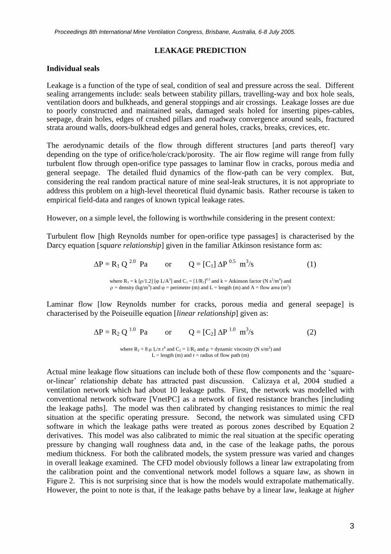
Actual mine leakage flow situations can include both of these flow components and the ‘square-
or-linear’ relationship debate has attracted past discussion. Calizaya et al, 2004 studied a
ventilation network which had about 10 leakage paths. First, the network was modelled with
conventional network software [VnetPC] as a network of fixed resistance branches [including
the leakage paths]. The model was then calibrated by changing resistances to mimic the real
situation at the specific operating pressure. Second, the network was simulated using CFD
software in which the leakage paths were treated as porous zones described by Equation 2
derivatives. This model was also calibrated to mimic the real situation at the specific operating
pressure by changing wall roughness data and, in the case of the leakage paths, the porous
medium thickness. For both the calibrated models, the system pressure was varied and changes
in overall leakage examined. The CFD model obviously follows a linear law extrapolating from
the calibration point and the conventional network model follows a square law, as shown in
Figure 2. This is not surprising since that is how the models would extrapolate mathematically.
However, the point to note is that, if the leakage paths behave by a linear law, leakage at higher
Proceedings 8th International Mine Ventilation Congress, Brisbane, Australia, 6-8 July 2005.
4
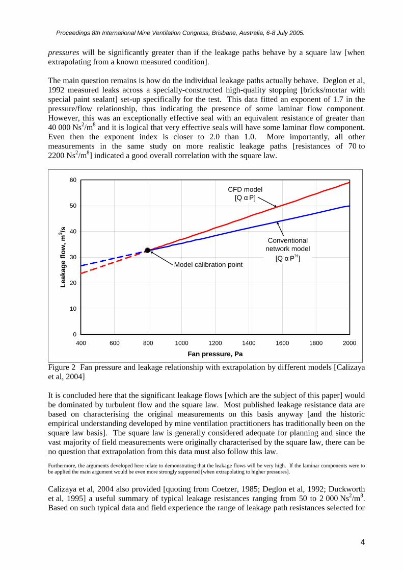
pressures will be significantly greater than if the leakage paths behave by a square law [when
extrapolating from a known measured condition].
The main question remains is how do the individual leakage paths actually behave. Deglon et al,
1992 measured leaks across a specially-constructed high-quality stopping [bricks/mortar with
special paint sealant] set-up specifically for the test. This data fitted an exponent of 1.7 in the
pressure/flow relationship, thus indicating the presence of some laminar flow component.
However, this was an exceptionally effective seal with an equivalent resistance of greater than
40 000 Ns2/m
8 and it is logical that very effective seals will have some laminar flow component.
Even then the exponent index is closer to 2.0 than 1.0. More importantly, all other
measurements in the same study on more realistic leakage paths [resistances of 70 to
2200 Ns2/m
8] indicated a good overall correlation with the square law.
0
10
20
30
40
50
60
400 600 800 1000 1200 1400 1600 1800 2000
Fan pressure, Pa
Le
ak
ag
e f
low
, m
3/s
Model calibration point
CFD model
[Q α P]
Conventional
network model
[Q α P½
]
Figure 2 Fan pressure and leakage relationship with extrapolation by different models [Calizaya
et al, 2004]
It is concluded here that the significant leakage flows [which are the subject of this paper] would
be dominated by turbulent flow and the square law. Most published leakage resistance data are
based on characterising the original measurements on this basis anyway [and the historic
empirical understanding developed by mine ventilation practitioners has traditionally been on the
square law basis]. The square law is generally considered adequate for planning and since the
vast majority of field measurements were originally characterised by the square law, there can be
no question that extrapolation from this data must also follow this law.
Furthermore, the arguments developed here relate to demonstrating that the leakage flows will be very high. If the laminar components were to be applied the main argument would be even more strongly supported [when extrapolating to higher pressures].
Calizaya et al, 2004 also provided [quoting from Coetzer, 1985; Deglon et al, 1992; Duckworth
et al, 1995] a useful summary of typical leakage resistances ranging from 50 to 2 000 Ns2/m
8.
Based on such typical data and field experience the range of leakage path resistances selected for
Proceedings 8th International Mine Ventilation Congress, Brisbane, Australia, 6-8 July 2005.
5
this study was from ‘Very Poor’ at 100 Ns2/m
8 to ‘Very Good’ at 25 000 Ns
2/m
8, see Table 1.
[Note that McPherson, 1993 quotes a range of 50 to 5 000 Ns2/m
8, as an example].
In order to relate these values to practical physical terms, consider [for example] all leaks on a
particular structure as a single 150 mm hole. [This will have the same area as a 0.9 mm crack
around the perimeter of an 8.0 m x 1.4 m seal, for example]. For orifice-type flow, this leak
resistance value can be calculated from standard equations to be 5 000 Ns2/m
8. These equivalent
parameters for the other categories selected for this study are given in Table 1.
Table 1 Range of typical leakage resistances
Category Resistance Equivalent hole Equivalent crack Leak at 500 Pa
Very Poor 100 Ns2/m
8 400 mm 6.7 mm 2.2 m
3/s
Poor 300 Ns2/m
8 310 mm 4.0 mm 1.3 m
3/s
Average 1 000 Ns2/m
8 230 mm 2.2 mm 0.7 m
3/s
Good 5 000 Ns2/m
8 150 mm 0.9 mm 0.3 m
3/s
Very Good 25 000 Ns2/m
8 100 mm 0.4 mm 0.2 m
3/s
Network modelling of full system
Leakage is a function of the pressure across the seal [and temperature and density of the leakage
flow]. The operating pressure [and temperature/density] varies throughout any network and,
with the multiplicity of seals under consideration, it is necessary to make use of mine network
computer simulation.
Accordingly, the VUMA-network 2.0 [Marx, 2001] simulation program was used to establish the
full network effect of the multiplicity of seals and leakage paths. The VUMA-network package
is particularly well suited to this type of planning study since it allows for the full simulation of
the full aerodynamic and thermodynamic behaviour taking account of the wide variations in
pressure, temperature and particularly density throughout the network. These features are
essential for deep hot-rock mines in order to draw fully meaningful conclusions. VUMA-
network uses algorithms based on theoretical and empirical models that have been developed and
verified over a period of three decades and represents the state-of-the-art in this type of
simulation.
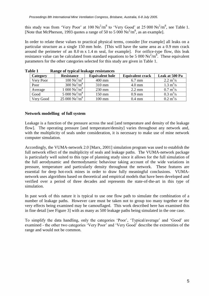
In past work of this nature it is typical to use one flow path to simulate the combination of a
number of leakage paths. However care must be taken not to group too many together or the
very effects being examined may be camouflaged. This work described here has examined this
in fine detail [see Figure 3] with as many as 500 leakage paths being simulated in the one case.
To simplify the data handling, only the categories ‘Poor’, ‘Typical/average’ and ‘Good’ are
examined - the other two categories ‘Very Poor’ and ‘Very Good’ describe the extremities of the
range and would not be common.
Proceedings 8th International Mine Ventilation Congress, Brisbane, Australia, 6-8 July 2005.
6
Figure 3 Ventilation network leakage lattice
MINE EXAMPLE A
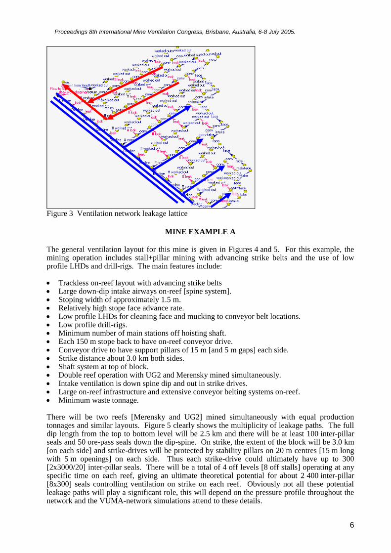
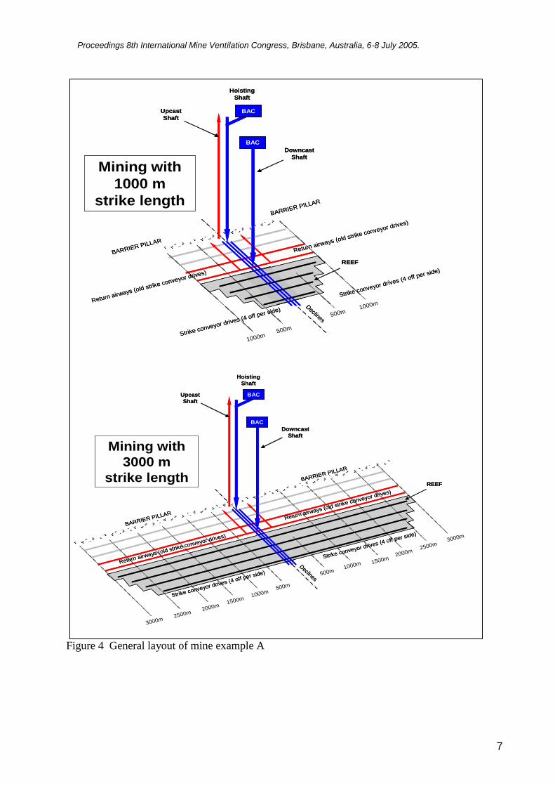
The general ventilation layout for this mine is given in Figures 4 and 5. For this example, the mining operation includes stall+pillar mining with advancing strike belts and the use of low profile LHDs and drill-rigs. The main features include: Trackless on-reef layout with advancing strike belts Large down-dip intake airways on-reef [spine system]. Stoping width of approximately 1.5 m. Relatively high stope face advance rate. Low profile LHDs for cleaning face and mucking to conveyor belt locations. Low profile drill-rigs. Minimum number of main stations off hoisting shaft. Each 150 m stope back to have on-reef conveyor drive. Conveyor drive to have support pillars of 15 m [and 5 m gaps] each side. Strike distance about 3.0 km both sides. Shaft system at top of block. Double reef operation with UG2 and Merensky mined simultaneously. Intake ventilation is down spine dip and out in strike drives. Large on-reef infrastructure and extensive conveyor belting systems on-reef. Minimum waste tonnage. There will be two reefs [Merensky and UG2] mined simultaneously with equal production tonnages and similar layouts. Figure 5 clearly shows the multiplicity of leakage paths. The full dip length from the top to bottom level will be 2.5 km and there will be at least 100 inter-pillar seals and 50 ore-pass seals down the dip-spine. On strike, the extent of the block will be 3.0 km [on each side] and strike-drives will be protected by stability pillars on 20 m centres [15 m long with 5 m openings] on each side. Thus each strike-drive could ultimately have up to 300 [2x3000/20] inter-pillar seals. There will be a total of 4 off levels [8 off stalls] operating at any specific time on each reef, giving an ultimate theoretical potential for about 2 400 inter-pillar [8x300] seals controlling ventilation on strike on each reef. Obviously not all these potential leakage paths will play a significant role, this will depend on the pressure profile throughout the network and the VUMA-network simulations attend to these details.
Proceedings 8th International Mine Ventilation Congress, Brisbane, Australia, 6-8 July 2005.
7
Figure 4 General layout of mine example A
Hoisting
Shaft
Downcast
Shaft
Upcast
Shaft
BAC
BAC
BARRIER PILLAR
BARRIER PILLAR
Declines
Strike conveyor drives (4 off per side)
Strike conveyor drives (4 off per side)
REEF
Return airways (old strike conveyor drives)
Return airways (old strike conveyor drives)
500m
1500m1000m
2000m
3000m2500m
3000m
2000m2500m
1500m
500m1000m
Mining with
3000 m
strike length
Hoisting
Shaft
Downcast
Shaft
Upcast
ShaftBAC
BAC
BARRIER PILLAR
BARRIER PILLAR
Declines
Strike conveyor drives (4 off per side)
Strike conveyor drives (4 off per side)
REEF
Return airways (old strike conveyor drives)
Return airways (old strike conveyor drives)
500m
1000m
500m1000m
Hoisting
Shaft
Downcast
Shaft
Upcast
ShaftBAC
BAC
BARRIER PILLAR
BARRIER PILLAR
Declines
Strike conveyor drives (4 off per side)
Strike conveyor drives (4 off per side)
REEF
Return airways (old strike conveyor drives)
Return airways (old strike conveyor drives)
500m
1000m
500m1000m
Mining with
1000 m
strike length
Proceedings 8th International Mine Ventilation Congress, Brisbane, Australia, 6-8 July 2005.
8
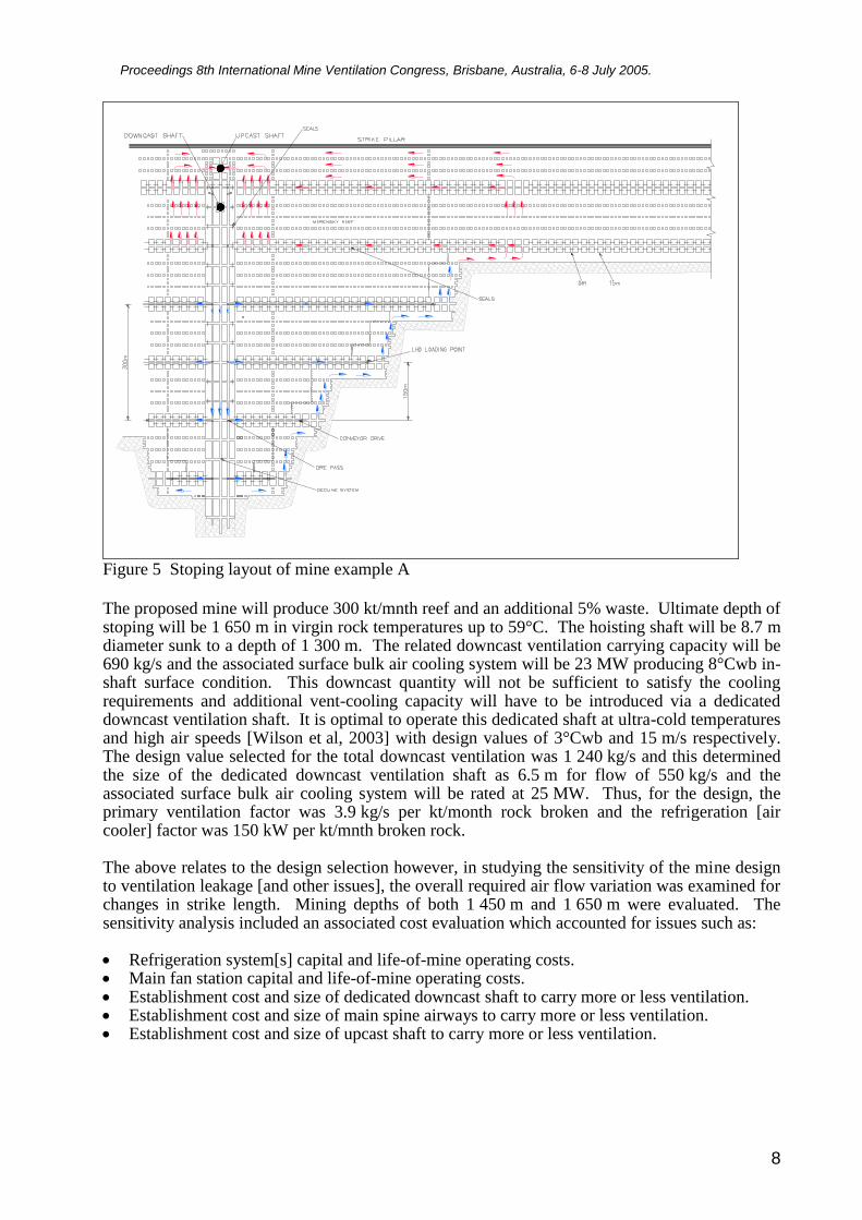
Figure 5 Stoping layout of mine example A
The proposed mine will produce 300 kt/mnth reef and an additional 5% waste. Ultimate depth of stoping will be 1 650 m in virgin rock temperatures up to 59°C. The hoisting shaft will be 8.7 m diameter sunk to a depth of 1 300 m. The related downcast ventilation carrying capacity will be 690 kg/s and the associated surface bulk air cooling system will be 23 MW producing 8°Cwb in-shaft surface condition. This downcast quantity will not be sufficient to satisfy the cooling requirements and additional vent-cooling capacity will have to be introduced via a dedicated downcast ventilation shaft. It is optimal to operate this dedicated shaft at ultra-cold temperatures and high air speeds [Wilson et al, 2003] with design values of 3°Cwb and 15 m/s respectively. The design value selected for the total downcast ventilation was 1 240 kg/s and this determined the size of the dedicated downcast ventilation shaft as 6.5 m for flow of 550 kg/s and the associated surface bulk air cooling system will be rated at 25 MW. Thus, for the design, the primary ventilation factor was 3.9 kg/s per kt/month rock broken and the refrigeration [air cooler] factor was 150 kW per kt/mnth broken rock. The above relates to the design selection however, in studying the sensitivity of the mine design to ventilation leakage [and other issues], the overall required air flow variation was examined for changes in strike length. Mining depths of both 1 450 m and 1 650 m were evaluated. The sensitivity analysis included an associated cost evaluation which accounted for issues such as: Refrigeration system[s] capital and life-of-mine operating costs. Main fan station capital and life-of-mine operating costs. Establishment cost and size of dedicated downcast shaft to carry more or less ventilation. Establishment cost and size of main spine airways to carry more or less ventilation. Establishment cost and size of upcast shaft to carry more or less ventilation.
Proceedings 8th International Mine Ventilation Congress, Brisbane, Australia, 6-8 July 2005.
9
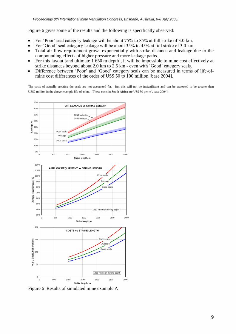
Figure 6 gives some of the results and the following is specifically observed: For ‘Poor’ seal category leakage will be about 75% to 85% at full strike of 3.0 km. For ‘Good’ seal category leakage will be about 35% to 45% at full strike of 3.0 km. Total air flow requirement grows exponentially with strike distance and leakage due to the
compounding effects of higher pressure and more leakage paths. For this layout [and ultimate 1 650 m depth], it will be impossible to mine cost effectively at
strike distances beyond about 2.0 km to 2.5 km - even with ‘Good’ category seals. Difference between ‘Poor’ and ‘Good’ category seals can be measured in terms of life-of-
mine cost differences of the order of US$ 50 to 100 million [base 2004].
The costs of actually erecting the seals are not accounted for. But this will not be insignificant and can be expected to be greater than
US$2 million in the above example life-of-mine. [These costs in South Africa are US$ 50 per m2, base 2004].
0%
10%
20%
30%
40%
50%
60%
70%
80%
0 500 1000 1500 2000 2500 3000
Strike length, m
Leakag
e %
Poor seals
Good seals
Average
AIR LEAKAGE vs STRIKE LENGTH
1650m depth
1450m depth
30%
40%
50%
60%
70%
80%
90%
100%
110%
120%
0 500 1000 1500 2000 2500 3000
Strike length, m
Air
flo
w r
eq
uir
em
en
ts, %
1450 m mean mining depth
Poor seals
Good seals
Average
AIRFLOW REQUIRMENT vs STRIKE LENGTH
0
50
100
150
200
0 500 1000 1500 2000 2500 3000
Strike length, m
V &
C C
os
ts,
$U
S m
illi
on
s
1450 m mean mining depth
Poor seals
Good seals
Average
COSTS vs STRIKE LENGTH
Figure 6 Results of simulated mine example A
Proceedings 8th International Mine Ventilation Congress, Brisbane, Australia, 6-8 July 2005.
10
For this project the vent-cooling issues would have accounted for some 30% of total project capital and 50% of the life-of-mine power costs. Indeed this project was not viable in this format because of the following main reasons: vent-cooling costs, diesel machinery costs and ore dilution effects. This project was later re-invented in a mine design that included footwall drive systems, scraper winch systems and multiple levels [amongst other issues].
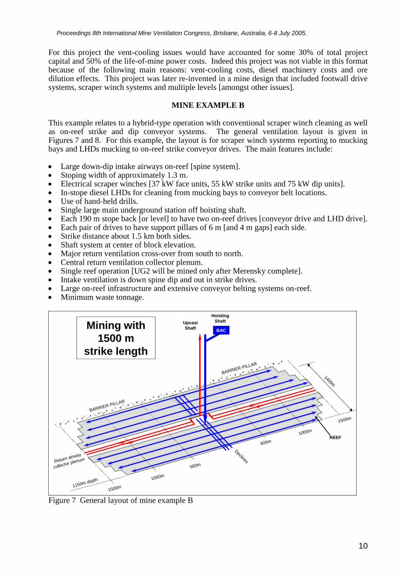
MINE EXAMPLE B This example relates to a hybrid-type operation with conventional scraper winch cleaning as well as on-reef strike and dip conveyor systems. The general ventilation layout is given in Figures 7 and 8. For this example, the layout is for scraper winch systems reporting to mucking bays and LHDs mucking to on-reef strike conveyor drives. The main features include: Large down-dip intake airways on-reef [spine system]. Stoping width of approximately 1.3 m. Electrical scraper winches [37 kW face units, 55 kW strike units and 75 kW dip units]. In-stope diesel LHDs for cleaning from mucking bays to conveyor belt locations. Use of hand-held drills. Single large main underground station off hoisting shaft. Each 190 m stope back [or level] to have two on-reef drives [conveyor drive and LHD drive]. Each pair of drives to have support pillars of 6 m [and 4 m gaps] each side. Strike distance about 1.5 km both sides. Shaft system at center of block elevation. Major return ventilation cross-over from south to north. Central return ventilation collector plenum. Single reef operation [UG2 will be mined only after Merensky complete]. Intake ventilation is down spine dip and out in strike drives. Large on-reef infrastructure and extensive conveyor belting systems on-reef. Minimum waste tonnage.
Hoisting
ShaftUpcast
ShaftBAC
BARRIER PILLAR
BARRIER PILLAR
Declines
REEF
Return airway
collector plenum
500m
1000m
1500m
1500m
1000m
500m
Mining with
1500 m
strike length
1150m depth
1400m
Figure 7 General layout of mine example B
Proceedings 8th International Mine Ventilation Congress, Brisbane, Australia, 6-8 July 2005.
11
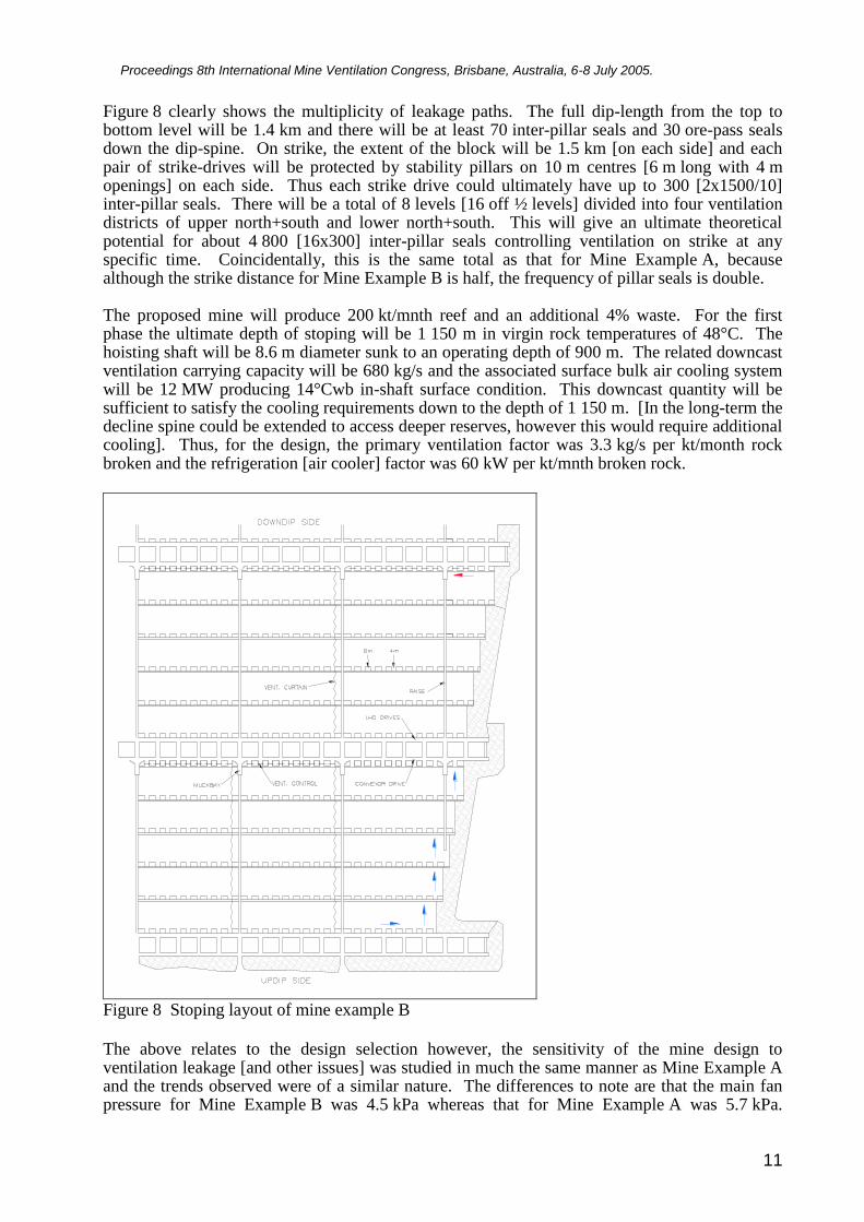
Figure 8 clearly shows the multiplicity of leakage paths. The full dip-length from the top to bottom level will be 1.4 km and there will be at least 70 inter-pillar seals and 30 ore-pass seals down the dip-spine. On strike, the extent of the block will be 1.5 km [on each side] and each pair of strike-drives will be protected by stability pillars on 10 m centres [6 m long with 4 m openings] on each side. Thus each strike drive could ultimately have up to 300 [2x1500/10] inter-pillar seals. There will be a total of 8 levels [16 off ½ levels] divided into four ventilation districts of upper north+south and lower north+south. This will give an ultimate theoretical potential for about 4 800 [16x300] inter-pillar seals controlling ventilation on strike at any specific time. Coincidentally, this is the same total as that for Mine Example A, because although the strike distance for Mine Example B is half, the frequency of pillar seals is double. The proposed mine will produce 200 kt/mnth reef and an additional 4% waste. For the first phase the ultimate depth of stoping will be 1 150 m in virgin rock temperatures of 48°C. The hoisting shaft will be 8.6 m diameter sunk to an operating depth of 900 m. The related downcast ventilation carrying capacity will be 680 kg/s and the associated surface bulk air cooling system will be 12 MW producing 14°Cwb in-shaft surface condition. This downcast quantity will be sufficient to satisfy the cooling requirements down to the depth of 1 150 m. [In the long-term the decline spine could be extended to access deeper reserves, however this would require additional cooling]. Thus, for the design, the primary ventilation factor was 3.3 kg/s per kt/month rock broken and the refrigeration [air cooler] factor was 60 kW per kt/mnth broken rock.
Figure 8 Stoping layout of mine example B
The above relates to the design selection however, the sensitivity of the mine design to ventilation leakage [and other issues] was studied in much the same manner as Mine Example A and the trends observed were of a similar nature. The differences to note are that the main fan pressure for Mine Example B was 4.5 kPa whereas that for Mine Example A was 5.7 kPa.
Proceedings 8th International Mine Ventilation Congress, Brisbane, Australia, 6-8 July 2005.
12
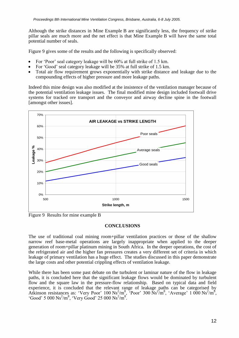
Although the strike distances in Mine Example B are significantly less, the frequency of strike pillar seals are much more and the net effect is that Mine Example B will have the same total potential number of seals. Figure 9 gives some of the results and the following is specifically observed: For ‘Poor’ seal category leakage will be 60% at full strike of 1.5 km. For ‘Good’ seal category leakage will be 35% at full strike of 1.5 km. Total air flow requirement grows exponentially with strike distance and leakage due to the
compounding effects of higher pressure and more leakage paths. Indeed this mine design was also modified at the insistence of the ventilation manager because of the potential ventilation leakage issues. The final modified mine design included footwall drive systems for tracked ore transport and the conveyor and airway decline spine in the footwall [amongst other issues].
0%
10%
20%
30%
40%
50%
60%
70%
500 1000 1500
Strike length, m
Le
akag
e %
Poor seals
Good seals
Average seals
AIR LEAKAGE vs STRIKE LENGTH
Figure 9 Results for mine example B
CONCLUSIONS
The use of traditional coal mining room+pillar ventilation practices or those of the shallow narrow reef base-metal operations are largely inappropriate when applied to the deeper generation of room+pillar platinum mining in South Africa. In the deeper operations, the cost of the refrigerated air and the higher fan pressures creates a very different set of criteria in which leakage of primary ventilation has a huge effect. The studies discussed in this paper demonstrate the large costs and other potential crippling effects of ventilation leakage. While there has been some past debate on the turbulent or laminar nature of the flow in leakage paths, it is concluded here that the significant leakage flows would be dominated by turbulent flow and the square law in the pressure-flow relationship. Based on typical data and field experience, it is concluded that the relevant range of leakage paths can be categorised by Atkinson resistances as: ‘Very Poor’ 100 Ns
2/m
8, ‘Poor’ 300 Ns
2/m
8, ‘Average’ 1 000 Ns
2/m
8,
‘Good’ 5 000 Ns2/m
8, ‘Very Good’ 25 000 Ns
2/m
8.
Proceedings 8th International Mine Ventilation Congress, Brisbane, Australia, 6-8 July 2005.
13
For the two mine examples examined, the trends in ventilation leakage and related costs were similar. For the ‘Poor’ seal category, leakage would be about 60% to 85% at extended strike distances while, for the ‘Good’ seal category, this would be about 35% to 45%. The total air flow [and refrigeration] requirement grow exponentially with strike distance and leakage due to the compounding effects of higher pressure and more leakage paths. The work demonstrates that beyond certain depths, dip and strike distances, the leakage could
become so great that it will be impossible to mine cost effectively with these layouts - even with
‘Good’ category seals. In the larger-deeper mine example, the overall cost difference between
‘Poor’ and ‘Good’ will be of the order of US$ 50 to 100 million. For this example, the vent-
cooling issues would account for some 30% of total project capital and 50% of the life-of-mine
power costs. Indeed in both these examples, the projects were not considered viable in the
original format. One of the main reasons for this was the enlarged vent-cooling costs due to
leakage and the strategic risk it posed. In both cases the mine design was modified to include
footwall drive systems - the cost of which could be justified by the reduced potential for leakage
and the reduced strategic risk of impairing long-term operating effectiveness. Acknowledgement
The permission of Impala Mines Ltd to present this paper is gratefully acknowledged.
References
Burrows J ed, 1982. Environmental Engineering in South African Mines. Mine Ventilation
Society of South Africa.
Calizaya F, Duckworth I J, Wallace K G, 2004. Studies of air leakage in underground mines
using CFD. Proc. of the 10th
US Mine Ventilation Symposium, Anchorage, Alaska.
Coetzer W J, 1985. Use of sealant paint to seal leakage through ventilation stoppings constructed
from pre-cast concrete bricks. Journal of the Mine Ventilation Society of South Africa,
January 1985.
Deglon P and Hemp R., 1992. An evaluation of parameters to be used in colliery ventilation.
Proc. of the 5th
International Mine Ventilation Congress. Mine Ventilation Society of South
Africa, Johannesburg.
Duckworth I J, Wallace K G and Wise R, 1995. Ventilation, planning and design of the Skyline
Mines. Proc. of the 7th
US Mine Ventilation Symposium, SME, Littleton, USA.
McPherson M J, 1993. Subsurface Ventilation and Environmental Engineering. Chapman and
Hall, London
Marx W M, von Glehn F H, Bluhm S, Biffi M, 2001. VUMA [ventilation of underground mine
atmospheres] a mine ventilation and cooling network simulation tool. Proc. of the 7th
International Mine Ventilation Congress. Cracow, Poland.
Wilson R, Bluhm S, Smit H, Funnell R, 2003. Surface bulk air cooler concepts producing ultra-
cold air and utilising ice thermal storage. Journal of the Mine Ventilation Society of South
Africa, Oct/Dec 2003.